

Page 1
INSTRUCTION MANUAL
MANUEL D'INSTRUCTIONS
MANUAL DE INSTRUCCIONES
CS-AW7020 CS-AW7040
CS-AW7220 CS-AW7240
CS-AW7020 CS-AW7220
CS-AW7040 CS-AW7240
For Customer Use:
Enter below the Model No, and Serial
No, which is located either on the rear
or bottom of the speaker unit. Retain
this information for future reference.
Model No.
Serial No.
LVT1743-001A
SUBWOOFER
CAISSON DE GRAVE
ENGLISH
FRANÇAISESPAŃOL
Page 2
Thank you for purchasing the ARSENAL Car Stereo Speaker. These Speakers can be
mounted in the trunk of your vehicle. For the secure installation and perfect operation
of your speakers, please read the following carefully.
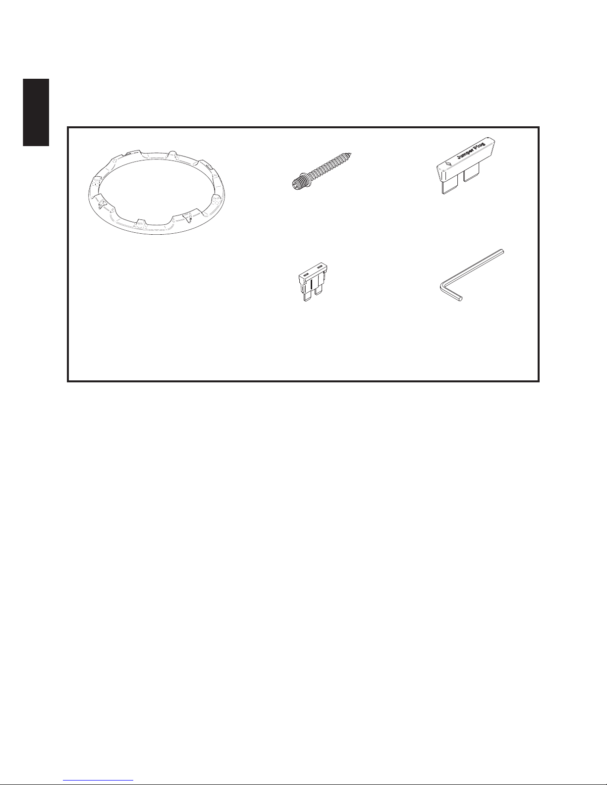
Parts
For proper installation and use
1.Before connecting the speakers to the amplifier, confirm that the power has been
turned off. The click noise generated by the connection if the power is on may
damage the speakers.
2.The amplifier and speakers should be connected between corresponding terminals,
i.e. left to left, and right to right, as well as "+" to "+", and "–" to "–". Connection with
reversed polarity will degrade the quality of stereo reproduction.
3.Do not subject the speakers to excessive input. The power handling capacity of the
CS-AW7020/CS-AW7040/CS-AW7220/CS-AW7240 is 600 watts (R.M.S. MUSIC
POWER). Any excessive input may damage the speakers.
4.The CS-AW7020/CS-AW7040/CS-AW7220/CS-AW7240 has an impedance of 2Ω
,4Ω,8Ω. Make sure that the output impedance of the amplifier's speaker terminal is
rated at 2Ω,4Ω,8Ω.
5.When cleaning the speakers, use a soft cloth and wipe the surface gently. Do not
apply thinner or solvent.
6.Be sure to carefully follow the instructions for:
Cable Connections
Fuse Replacement
Switching the Impedance Selector
Subwoofer Mounting and Smart Trim Ring Installation
Consult Page 19 of this Instruction Manual for details on these procedures.
1. Grille
5. Hexagon socket
screw keys
4. Fuse (10A) x 2
3. Jump2. Screw x 10
- 2 -
ENGLISH
Page 3
SERIES PARALLEL
Input Bi-Amp Input
Only
+ +
-
-
JUMPER
SERIES PARALLEL
Input Bi-Amp Input
Only
+
+
-
-
Jumper Plug
JUMPER
SERIES PARALLEL
Input Bi-Amp Input
Only
+
+
-
-
Jumper Plug
JUMPER
SERIES PARALLEL
Input Bi-Amp Input
Only
+
+
-
-
Jumper Plug
JUMPER
SERIES PARALLEL
Input Bi-Amp Input
Only
+
+
-
-
Jumper Plug
JUMPER
SERIES PARALLEL
Input Bi-Amp Input
Only
+
+
-
-
Jumper Plug
JUMPER
SERIES PARALLEL
Input Bi-Amp Input
Only
+
+
-
-
Jumper Plug
JUMPER
SERIES PARALLEL
Input Bi-Amp Input
Only
+
+
-
-
Jumper Plug
JUMPER
SERIES PARALLEL
Input Bi-Amp Input
Only
+
+
-
-
Jumper Plug
JUMPER
SERIES PARALLEL
Input Bi-Amp Input
Only
+
+
-
-
Jumper Plug
JUMPER
SERIES PARALLEL
Input Bi-Amp Input
Only
+
+
-
-
Jumper Plug
JUMPER
SERIES PARALLEL
Input Bi-Amp Input
Only
+
+
-
-
Jumper Plug
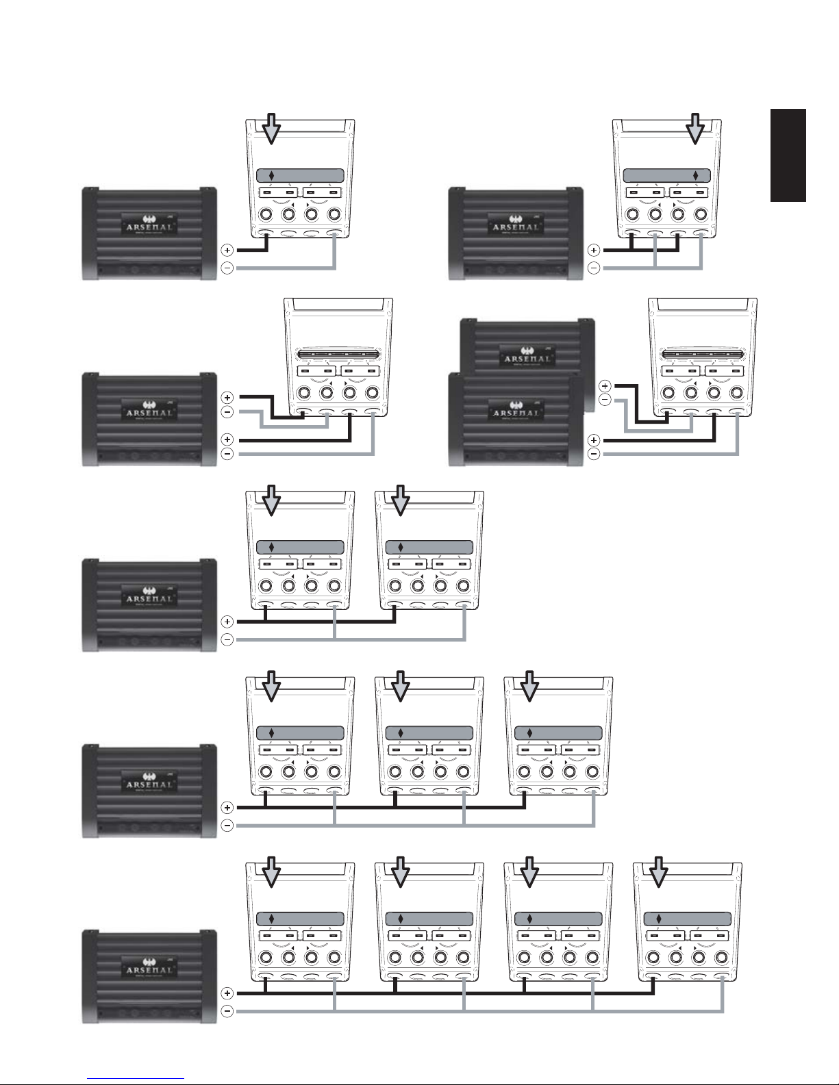
1 Mono Amplifier
1 Subwoofer
Jumper set to Series
8Ω(4Ω+4Ω) Load
4Ω
2Ω
4Ω
4Ω
4Ω4Ω
8Ω
4Ω
Mono
SERIES PARALLEL
Input Bi-Amp Input
Only
+ +
-
-
Stereo
Mono
4Ω
8Ω 8Ω
4Ω
4Ω 4Ω 4Ω
Mono
4Ω
8Ω
2.6Ω
4Ω
Mono
4Ω
8Ω
2Ω
4Ω
4Ω
8Ω
4Ω
4Ω
8Ω
4Ω
4Ω
8Ω
4Ω
4Ω
8Ω
4Ω 4Ω
8Ω
4Ω
Mono
Mono
Mono
1 Mono Amplifier
1 Subwoofer
Jumper set to Parallel
8Ω(4Ω+4Ω) Load
4Ω 2-Chan
1 2ch Amplifier
1 Subwoofer
Jumper is Removed
4Ω Load
1 Mono Amplifier
2 Subwoofers
Jumper set to Series
Subwoofers wired in Parallel
4Ω Load
1 Mono Amplifier
3 Subwoofers
Jumper set to Series
Subwoofers wired in Parallel
2.6Ω Load
1 Mono Amplifier
4 Subwoofers
Jumper set to Series
Subwoofers wired in Parallel
2Ω Load
Dual 4 Ω Application Diagrams
- 3 -
Bi-Amp Configuration 2 Mono Amplifiers
1 Subwoofer Jumper is Removed 4Ω Load
ENGLISH
*JUMPER is Removed *JUMPER is Removed
Page 4

SERIES PARALLEL
Input Bi-Amp Input
Only
+ +
-
-
JUMPER
SERIES PARALLEL
Input Bi-Amp Input
Only
+
+
-
-
Jumper Plug
JUMPER
SERIES PARALLEL
Input Bi-Amp Input
Only
+
+
-
-
Jumper Plug
JUMPER
SERIES PARALLEL
Input Bi-Amp Input
Only
+
+
-
-
Jumper Plug
JUMPER
SERIES PARALLEL
Input Bi-Amp Input
Only
+
+
-
-
Jumper Plug
JUMPER
SERIES PARALLEL
Input Bi-Amp Input
Only
+
+
-
-
Jumper Plug
JUMPER
SERIES PARALLEL
Input Bi-Amp Input
Only
+
+
-
-
Jumper Plug
JUMPER
SERIES PARALLEL
Input Bi-Amp Input
Only
+
+
-
-
Jumper Plug
JUMPER
SERIES PARALLEL
Input Bi-Amp Input
Only
+
+
-
-
Jumper Plug
JUMPER
SERIES PARALLEL
Input Bi-Amp Input
Only
+
+
-
-
Jumper Plug
JUMPER
SERIES PARALLEL
Input Bi-Amp Input
Only
+
+
-
-
Jumper Plug
JUMPER
SERIES PARALLEL
Input Bi-Amp Input
Only
+
+
-
-
Jumper Plug
1 Mono Amplifier
1 Subwoofer
Jumper set to Series
4Ω(2Ω+2Ω) Load
2Ω
1Ω
2Ω
2Ω
2Ω2Ω
4Ω
2Ω
Mono
SERIES PARALLEL
Input Bi-Amp Input
Only
+ +
-
-
Stereo
Mono
2Ω
4Ω 4Ω
2Ω
2Ω 2Ω 2Ω
Mono
2Ω
4Ω
1.3Ω
2Ω
Mono
2Ω
4Ω
1Ω
2Ω
2Ω
4Ω
2Ω
2Ω
4Ω
2Ω
2Ω
4Ω
2Ω
2Ω
4Ω
2Ω 2Ω
4Ω
2Ω
Mono
Mono
Mono
1 Mono Amplifier
1 Subwoofer
Jumper set to Parallel
4Ω(2Ω+2Ω) Load
2Ω 2-Chan
1 2ch Amplifier
1 Subwoofer
Jumper is Removed
2Ω Load
1 Mono Amplifier
2 Subwoofers
Jumper set to Series
Subwoofers wired in Parallel
2Ω Load
1 Mono Amplifier
3 Subwoofers
Jumper set to Series
Subwoofers wired in Parallel
1.3Ω Load
1 Mono Amplifier
4 Subwoofers
Jumper set to Series
Subwoofers wired in Parallel
1Ω Load
Dual 2 Ω Application Diagrams
- 4 -
Bi-Amp Configuration 2 Mono Amplifiers
1 Subwoofer Jumper is Removed 2Ω Load
ENGLISH
*JUMPER is Removed *JUMPER is Removed
Page 5

C
C
B
A
G
H
I
B
A
CS-AW7020 / CS-AW7040 CS-AW7220 / CS-AW7240
A 15-13/32 inch (391.7 mm)
16-13/32 inch (417.1 mm)
B 15-13/32 inch (391.7 mm)
16-13/32 inch (417.1 mm)
C
11-13/32 inch (290.1 mm) 13-29/32 inch (353.6 mm)
D
9-4/32 inch (232 mm) 10-14/32 inch (275.9 mm)
E
9-23/32 inch (247 mm) 11-10/32 inch (295 mm)
FG4/32 inch (3 mm) 4/32 inch (3 mm)
1.57 ft3 (0.045 m3) 2.17 ft3 (0.062 m3)
CS-AW7020 / CS-AW7040 CS-AW7220 / CS-AW7240
A 15-13/32 inch (391.7 mm) 15-13/32 inch (391.7 mm)
B
18-13/32 inch (467.9 mm) 18-13/32 inch (467.9 mm)
C
13-13/32 inch (340.9 mm) 15-13/32 inch (391.7 mm)
D
9-23/32 inch (247 mm) 10-14/32 inch (275.9 mm)
E
9-23/32 inch (247 mm) 11-10/32 inch (295 mm)
F
4/32 inch (3 mm) 4/32 inch (3 mm)
G
1 inch (25.4 mm) 1 inch (25.4 mm)
H
13 inch (330.2 mm) 14 inch (355.6 mm)
IJ13-19/32 inch (345.4 mm) 13-6/32 inch (335.3 mm)
1.85 ft
3
(0.052 m3) 2.54 ft3 (0.072 m3)
To install the ported enclosure
When the speaker cannot be attached in the car, make the sealed enclosure as recommended in the table below—20 mm (3/4 inch) MDF is also
recommended for the enclosure materials.
To install the sealed enclosure
When the speaker cannot be attached in the car, make the sealed enclosure as recommended in the table below—20 mm (3/4 inch) MDF is also
recommended for the enclosure materials.
Front & Rear Bae Boards (x 2)
Left & Right Sides (x 2)
Top & Bottom Sides (x 2)
* Screw: Dia. 4mm x 50mm (x 8) (supplied)
Mounting Hole
Dimension
Front & Rear Bae Boards (x 2)
Left & Right Sides (x 2)
Top & Bottom Sides (x 2)
* Screw: Dia. 4mm x 50mm (x 8) (supplied)
Mounting Hole
Dimension
- 5-
ENGLISH
J : Internal Volume
G : Internal Volume
Page 6

- 6 -
ENGLISH
Nominal Impedance (Ω)
SPL : Sound pressure levelSPL (dB,1W/1M)
Displacement (Liter)
Hole Cutout Diameter (inch)
(mm)
Mounting Depth (inch)
(mm)
Re (Ω) Re : DC voice coil resistance
BL (T.M)
BL : Product of Flux density and
Effective Voicecoil-wire length
Vas (Liter)
Vas : Volume of air equal to the driver
compliance
Vas (CuFt)
Me : Effective massMe (g)
D (mm) D : Effective cone diameter
Fs : Driver free air resonanceFs (Hz)
Qms
Qms : Q of driver at Fs considering
only non-electrical resistance
Qes
Qes : Q of driver at Fs considering
only electrical resistance
Qts : Total Q of driver at FsQts
Pe [max.] (W)
Pe[max.] : Maximum continuous input
power
Xmax.(mm)
Xmax. : Maximum effective voicecoil
travel without distortion
Freq.Responce (Hz)
Magnet Mass (oz)
(g)
Voice Coil(Aluminum)Dia.(inch)
(mm)
Hvc (mm) Hvc : Voice coil Height
Hag (mm) Hag : Gap Height
NOTESParameters
parallel
83.49 dB
series seriesparallel
0.98 Ω 3.83 Ω 7.6 Ω1.92 Ω
6.85 13.75 17.218.68
17.08 L 16.98 L 18.28 L18.08 L
39.6 Hz 39.5 Hz 41.8 Hz41.7 Hz
10.261 10.282 9.1699.021
0.756 0.74 0.8240.83
0.704 0.691 0.7560.76
145.986 g 147.109 g 122.443 g124.084 g
0.6 ft
3
0.599 ft
3
0.65 ft
3
0.64 ft
3
83.54 dB 84.12 dB84.02 dB
25 ~500 Hz
6 - 14/32 inch
( 163.5 mm )
CS-AW7040CS-AW7020
2Ω + 2Ω 4Ω + 4Ω
Dia. 2 - 5/32 inch
54.5 mm
39.9 mm
10 mm
39.6 mm
Dia. 2 - 4/32 inch
53.59 mm
14.95 mm 14.8 mm
65.4 oz
( 1854.1 g )
600 W
Dia. 202 mm
Dia. 9 - 6/32 inch
( 233 mm )
0.123 ft
3
Nominal Impedance (Ω)
SPL : Sound pressure levelSPL (dB,1W/1M)
Displacement (Liter)
Hole Cutout Diameter (inch)
(mm)
Mounting Depth (inch)
(mm)
Re (Ω) Re : DC voice coil resistance
BL (T.M)
BL : Product of Flux density and
Effective Voicecoil-wire length
Vas (Liter)
Vas : Volume of air equal to the driver
compliance
Vas (CuFt)
Me : Effective massMe (g)
D (cm) D : Effective cone diameter
Fs : Driver free air resonanceFs (Hz)
Qms
Qms : Q of driver at Fs considering
only non-electrical resistance
Qes
Qes : Q of driver at Fs considering
only electrical resistance
Qts : Total Q of driver at FsQts
Pe [max.] (W)
Pe[max.] : Maximum continuous input
power
Xmax.(mm)
Xmax. : Maximum effective voicecoil
travel without distortion
Freq.Responce (Hz)
Magnet Mass (oz)
(g)
Voice Coil(Aluminum)Dia.(inch)
(mm)
Hvc (mm) Hvc : Voice coil Height
Hag (mm) Hag : Gap Height
NOTESParameters
parallel
85.13 dB
series seriesparallel
0.98 Ω 3.84 Ω 7.61 Ω1.94 Ω
6.84 13.72 19.149.56
38.7 L 38.76 L 35.05 L35.23 L
34.6 Hz 34.5 Hz 38 Hz37.9 Hz
10.277 10.089 9.0148.931
0.786 0.765 0.7810.794
0.73 0.711 0.7190.73
171.854 g 172.934 g 157.336 g157.028 g
1.37 ft
3
1.37 ft
3
1.24 ft
3
1.24 ft
3
85.2 dB 85.65 dB85.87 dB
23 ~500 Hz
7 - 6/32 inch
( 182.5 mm )
CS-AW7240CS-AW7220
2Ω + 2Ω 4Ω + 4Ω
Dia. 2 - 5/32 inch
( 54.5 mm )
39.9 mm
10 mm
39.6 mm
Dia. 2 - 4/32 inch
( 53.59 mm )
14.95 mm 14.8 mm
86.2 oz
( 2443.7 g )
600 W
Dia. 246 mm
Dia. 10 - 29/32 inch
( 277 mm )
0.18 ft
3
Page 7

1-9/32 inch
[ 32.69 mm ]
7-7/32 inch [ 182.5 mm ]
Dia. 10-28/32 inch [ 275.94 mm ]Dia. 9-4/32 inch [ 231.96 mm ]
1-9/32 inch
[ 32.51 mm ]
6-14/32 inch [ 163.5 mm ]
Dia. 11-20/32 inch
[ 295 mm ]
8-
Dia.
7/32
inch
[ 5.5 mm ] HOLES
Dia. 12-24/32 inch [ 324 mm ]
Dia. 12-12/32 inch [ 314 mm ]
Dia. 10-26/32 inch [ 275 mm ]
Dia. 10-14/32 inch [ 265 mm ]
Dia. 9-23/32 inch
[ 247 mm ]
8-
Dia.
7/32
inch
[ 5.5 mm ] HOLES
CS-AW7020 CS-AW7220
CS-AW7040 CS-AW7240
- 17 -
Page 8

Air Vented
Aluminum
Cast Basket
Integlated Dual-Layer
Cone construction
Woven Tinsel Lead
(Patent Pending)
Rapid Fire Impedance
Selector Speaker Terminal
( Patent Pending)
Dual Stacked
Strontium Magnet
Dual Diametric
Progressive Spider
Multi Mount Smart
Trim Ring
(Patent Pending)
Glass Fiber
Laminated
Hemp Cone
Hemp-Fiber Drive
Cone
Aluminum Voice
Coil Former
Santoprene Surround
4 (2+2) Layer Voice Coils
Aero Vent Bottom Plate
T3 Chassis (Thermal Transfer Technology)
Heat Transfer Silicon
Heat Transfer Silicon
- 18 -
Page 9

- 19 -
Page 10

TO OUR VALUED CUSTOMER
IS HERE TO HELP!
Do not attempt to service the product yourself
Caution
To prevent electrical shock, do not open the cabinet.
There are no user serviceable parts inside.
Please refer to qualified service personnel for repairs.
NEED HELP ON HOW TO HOOK UP?
NEED ASSISTANCE ON HOW TO OPERATE?
NEED TO LOCATE A JVC SERVICE CENTER?
LIKE TO PURCHASE ACCESSORIES?
THANK YOU FOR PURCHASING THIS JVC PRODUCT.
WE WANT TO HELP YOU ACHIEVE A PERFECT EXPERIENCE.
Remember to retain your Bill of Sale for Warranty Service.
TOLL FREE: 1(800)252-5722
http://www.jvc.com
Printed in China
EN, FR, SP
© 2007 Victor Company of Japan, Limited
 Loading...