

Page 1

No.51831
Aug. 2001
C-N14210
1
COPYRIGHT © 2001 VICTOR COMPANY OF JAPAN, LTD.
Aug. 2001
C-N14210
/S
CONTENTS
!
SPECIFICATIONS
・・・・・・・・・・・・・・・・・・・・・・・・・・・・・・・・
・・・・・・・・・・・・・・・・・・・・・・・・・・・・・・・・・・・・・・・・・・・・・・・・・・・・・・・・・・・・・・・・
・・・・・・・・・・・・・・・・・・・・・・・・・・・・・・・・ ・・・・・・・・・・・・・・・・・・・・・・・・・・・・・
・・・・・・・・・・・・・・・・・・・・・・・・・・・・・・・・・・・・・・・・・・・・・・・・・・・・・・・・・・
・・・・・・・・・・・・・・・・・・・・・・・・・・・・・
2
!
SAFETY PRECAUTIONS
・・・・・・・・・・・・・・・・・・・・・・・・・・・・・・・・
・・・・・・・・・・・・・・・・・・・・・・・・・・・・・・・・・・・・・・・・・・・・・・・・・・・・・・・・・・・・・・・・
・・・・・・・・・・・・・・・・・・・・・・・・・・・・・・・・ ・・・・・・・・・・・・・・・・・・・・・・・
・・・・・・・・・・・・・・・・・・・・・・・・・・・・・・・・・・・・・・・・・・・・・・
・・・・・・・・・・・・・・・・・・・・・・・
3
!
FEATURES
・・・・・・・・・・・・・・・・・・・・・・・・・・・・・・・・
・・・・・・・・・・・・・・・・・・・・・・・・・・・・・・・・・・・・・・・・・・・・・・・・・・・・・・・・・・・・・・・・
・・・・・・・・・・・・・・・・・・・・・・・・・・・・・・・・ ・・・・・・・・・・・・・・・・・・・・・・・・・・・・・・・・
・・・・・・・・・・・・・・・・・・・・・・・・・・・・・・・・・・・・・・・・・・・・・・・・・・・・・・・・・・・・・・・・
・・・・・・・・・・・・・・・・・・・・・・・・・・・・・・・・ ・・・
・・・・・・
・・・
4
!
FUNCTIONS
・・・・・・・・・・・・・・・・・・・・・・・・・・・・・・・・
・・・・・・・・・・・・・・・・・・・・・・・・・・・・・・・・・・・・・・・・・・・・・・・・・・・・・・・・・・・・・・・・
・・・・・・・・・・・・・・・・・・・・・・・・・・・・・・・・ ・・・・・・・・・・・・・・・・・・・・・・・・・・・・・・・・
・・・・・・・・・・・・・・・・・・・・・・・・・・・・・・・・・・・・・・・・・・・・・・・・・・・・・・・・・・・・・・・・
・・・・・・・・・・・・・・・・・・・・・・・・・・・・・・・・ ・・
・・・・
・・
5
!
SPECIFIC SERVICE INSTRUCTIONS
・・・・・・・・・・・・・・・・・・・・・・・・・・・・・・・・
・・・・・・・・・・・・・・・・・・・・・・・・・・・・・・・・・・・・・・・・・・・・・・・・・・・・・・・・・・・・・・・・
・・・・・・・・・・・・・・・・・・・・・・・・・・・・・・・・ ・・・・・・・・・・・・・
・・・・・・・・・・・・・・・・・・・・・・・・・・
・・・・・・・・・・・・・
6
!
SERVICE ADJUSTMENTS
・・・・・・・・・・・・・・・・・・・・・・・・・・・・・・・・
・・・・・・・・・・・・・・・・・・・・・・・・・・・・・・・・・・・・・・・・・・・・・・・・・・・・・・・・・・・・・・・・
・・・・・・・・・・・・・・・・・・・・・・・・・・・・・・・・ ・・・・・・・・・・・・・・・・・・・・・
・・・・・・・・・・・・・・・・・・・・・・・・・・・・・・・・・・・・・・・・・・
・・・・・・・・・・・・・・・・・・・・・
10
!
PARTS LIST
・・・・・・・・・・・・・・・・・・・・・・・・・・・・・・・・
・・・・・・・・・・・・・・・・・・・・・・・・・・・・・・・・・・・・・・・・・・・・・・・・・・・・・・・・・・・・・・・・
・・・・・・・・・・・・・・・・・・・・・・・・・・・・・・・・ ・・・・・・・・・・・・・・・・・・・・・・・・・・・・・・・・
・・・・・・・・・・・・・・・・・・・・・・・・・・・・・・・・・・・・・・・・・・・・・・・・・・・・・・・・・・・・・・・・
・・・・・・・・・・・・・・・・・・・・・・・・・・・・・・・・ ・・・・
25
★
OPERATING INSTRUCTIONS
★
STANDARD CIRCUIT DIAGRAM
・・・・・・・・・・・・・・・・・・・・・・・・・・・・・・・・
・・・・・・・・・・・・・・・・・・・・・・・・・・・・・・・・・・・・・・・・・・・・・・・・・・・・・・・・・・・・・・・・
・・・・・・・・・・・・・・・・・・・・・・・・・・・・・・・・ ・・・・・・・・・・・・・・・・
・・・・・・・・・・・・・・・・・・・・・・・・・・・・・・・・
・・・・・・・・・・・・・・・・
2-1
SER VICE MANUAL
COLOR TELEVISION
BASIC CHASSIS
FV4
Page 2
No. 51831
C-N14210
2
SPECIFICATIONS
Items Content
Dimensions (W
××××H××××
D)
14-3/8”×13-1/8”×14-3/4” / 36.4cm×33.4cm×37.4cm
Mass
19.8 Ibs / 9.0 kg
TV System and Color system
TV RF System
Sound System
CCIR(M)
NTSC BTSC System
TV Receiving Channels and Frequency
VL Band
VH Band
UHF Band
(02~06) 54MHz~88MHz
(07~13) 174MHz~216MHz
(14~69) 470MHz~806MHz
CATV Receiving Channels and Frequenc y
Low Band
High Band
Mid Band
Super Band
Hyper Ban d
Ultr a B a nd
Sub Mid Band
TV/CATV To tal Channel
(02~06, A-8 ) by (02~06&01)
(07~13) by (07~13)
(A~1) by (14~22)
(J~W) by (23~36)
(W+1~W+28) by (37~64)
(W+29~W+84) by (65~125)
(A8, A4~A1) by (0 1, 96~99)
180 Channels
Intermediate Frequency
Video IF Carrier
Sound IF Carrier
Color Sub Carrier
45.75MHz
41.25MHz (4.5MHz)
3.58MHz
Antenna Input Impedance
75Ω(VHF/UHF) Terminal, F-Type Connector
Power Input
120V AC, 60Hz
Power Consumpt ion
60W
Picture Tube
14” (34cm) M eas ur ed Diagon al l y
High Voltage
22.5kV±1kV (at zer o b eam current)
Speaker
3-1/16” (8cm) Round type
Audio Power Output
1W
Video Input
1Vp-p, 75
Ω
Audio Input
500mVrms ( -4dBs ), High Impedance
Earphone Jack
3.5mm mono mini jack
Remote Control Unit
RM-C205 (AA / R6 / UM-3 dry battery×2)
Design & specificat ions ar e s ubjec t to change without notice.
(54MHz~804MHz)
Page 3
No.51831
C-N14210
3
SAFETY PRECAUTIONS
1. The design of this product contains special hardware, many
circuits and components specially for safety purposes. For
continued protection, no changes should be made to the original
design unless authorized in writing by the manufacturer.
Replacement parts must be identical to those used in the original
circuits. Service should be performed by qualified personnel
only.
2. Alterations of the design or circuitry of the products should not be
made. Any design alterations or additions will void the
manuf act ur er 's w arranty and wil l fur t h er reli ev e the manufacturer
of responsi bility f or personal inj ury or pr operty dam age resul ting
therefrom.
3. Many electrical and mechanical parts in the products have
special safety-related charact eristics. Thes e characteristics are
often not evident f rom visual i nspection nor can t he protect ion
afforded by them n ecessar ily be obt ained by us ing rep lacem ent
componen ts rated f or higher voltag e, watt ag e, etc. R epl acem ent
parts that have t hese sp eci al safet y c h ar ac t er is tic s are ident if i ed
in the parts list of Service manual.
Electrical components
having such features are identified by shading on the
schemati cs a nd by (
!!!!
) on the parts list in Serv ice manu al.
The use of a s ubstitute repl ac ement which d oes not have the
same saf ety char acteristics as the rec ommended repl ac ement
part show n in the p arts list of S ervic e m anual m ay caus e s hoc k,
fire, or other hazards.
4.
Don't short b etween the LIVE side groun d a nd ISOLATED
(NEUTRAL) side ground or EARTH side ground when
repairing.
Some model's power circuit is partly different in the GND. The
difference of the GND is show n b y the LIVE : (") side GND, the
ISOLATED(NEUTRAL ) : (#) side GND and EARTH : ($) side
GND. Don't short between the LIVE side GND and
ISOLATED(NEUTRAL) side GND or EARTH side GND and
never meas ure with a measuri ng apparatus (osc illoscope etc .)
the LIVE side GND and ISOLATED(NEUTRAL) side GND or
EARTH side GND at the same time.
If above not e wi ll n ot b e kept, a fus e or any part s will be broken.
5. If any repair has been made to the chassis, it is recommended
that the B1 setting should be checked or adjusted (See
ADJUSTMENT OF B1 POWER SUPPLY).
6. The hig h voltage app lied to th e picture tu be must conf orm wit h
that specified in Service manual. Excessive high voltage can
cause an increase in X-Ray emission, arcing and possible
component damage, therefore operation under excessive high
voltag e conditions s hould be k ept to a mi nimum, or should be
prevented. If severe arcing occurs, remove the AC power
immediately and determine the cause by visual inspection
(incorrec t installati on, c racked or m elted high voltage harness,
poor solderi ng, etc.). To main tain the proper min imum level of
soft X-Ray emission, components in the high voltage circuitry
includin g the picture tu be must be the exact replacements or
alternatives approved by the manufacturer of the complete
product.
7. Do not check high voltage by drawing an arc. Use a high voltage
meter or a high voltage probe with a VTVM. Discharge the
picture tube bef ore attempting meter connection, by connect ing
a clip le ad to th e gr oun d fr am e and c on necti ng t h e oth er end of
the lead through a 10k! 2W resistor to the anod e butt on .
8. W hen servic e is required, obser ve the origin al lead dress . Extr a
precaut ion shou ld be gi ven to assure c orrect l ead dress in th e
high voltage circuit area. Where a short circuit has occurred,
those comp onents that in dicate evi denc e of overheating should
be replaced. Always use the manufacturer's replacement
components.
9.
Isolation Check
(Safety for Electrical Shock Hazard)
After re-assembling the product, always perform an isolation
check on the exposed metal parts of the cabinet (antenna
termin als , video/audio input and output term in als , Control kn obs ,
metal cabinet, screw"heads, ear phone jac k, control shafts, etc.)
to be sure the product is safe to operate without danger of
electrical shock.
(1)
Dielectr i c St rength Test
The isol ation b etween th e AC pr imar y circuit and all metal parts
expos ed t o the user , p ar tic u larly any exp osed metal part ha vi ng a
return p ath to the chassis should withst and a voltage of 3 000V
AC (r.m.s .) for a period of one secon d.
(. . . . W ithstand a voltage of 1100 V AC (r .m.s.) to an applianc e
rated up t o 120V, and 3000V AC (r. m.s.) t o an appl iance rat ed
200V or more, f or a peri od of one secon d.)
This method of test requir es test equip ment not gen erally f ound
in the service trade.
(2)
Leakage Current Check
Plug the AC lin e c or d dir ec tly into the AC outlet ( d o not use a line
isolation transformer during this check.). Using a "Leakage
Current Tester", measure the leakage current from each exposed
metal part of the cabinet, particularly any exposed metal part
having a return path to the chassis, to a known good earth
ground ( water pipe, etc.) . An y leak age c urr ent mus t not exceed
0.5mA AC (r.m.s.).
However, in tropical area, this must not exceed 0.2mA AC
(r.m.s.).
""""
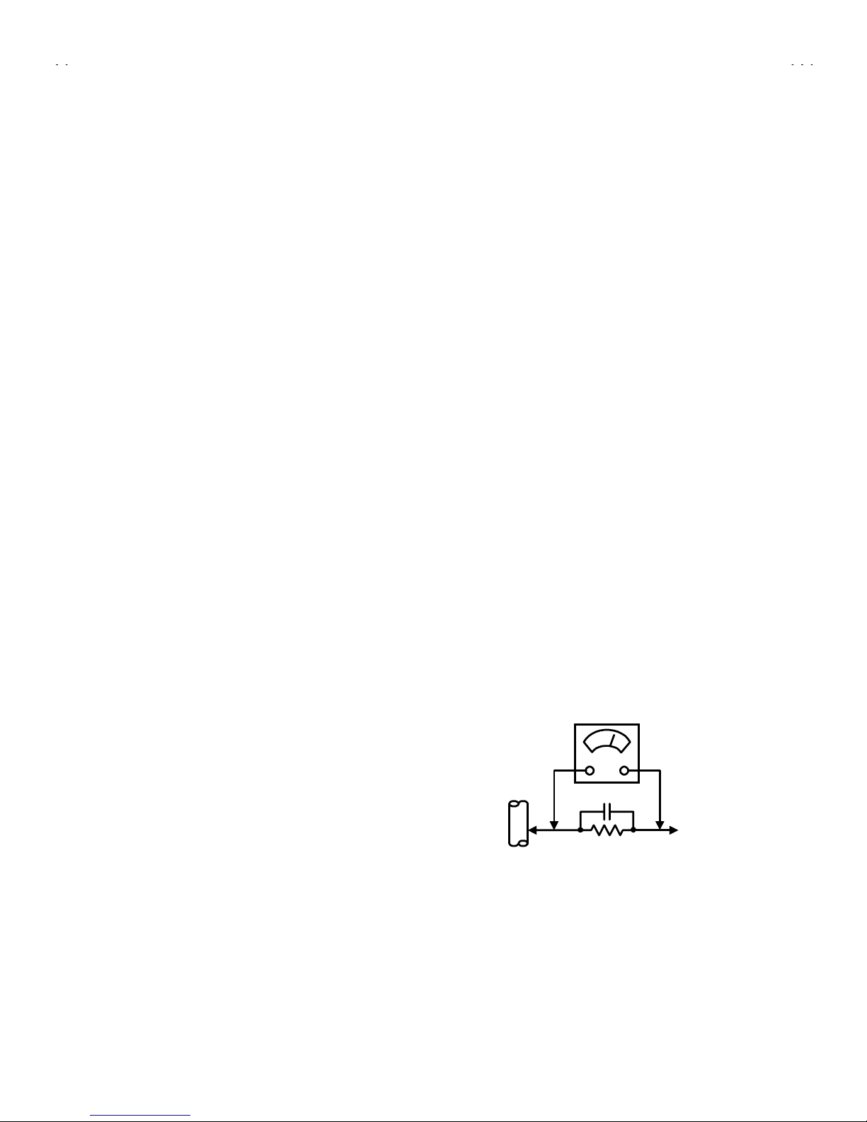
Alternate Check Method
Plug the AC lin e c or d dir ec tly into the AC outlet ( d o not use a line
isolati on transform er during t his check. ). Use an AC voltmet er
having 1000 ohms per volt or more sensiti vity in the following
manner. Connect a 1 500! 10W resistor paralleled by a 0.15#F
AC-typ e capacitor betw een an expos ed metal part and a known
good earth ground (water pipe, etc.). Measure the AC voltage
across the resistor with the AC voltmeter. Move the resistor
connect ion t o each exp os ed met al p art, part icul arl y any exp osed
metal part h avin g a return p ath to th e chassis, and measur e th e
AC voltag e across the resis tor. N ow, re verse th e plug in the AC
outlet and repeat each measurement. Any voltage measured
must not exceed 0.75V AC (r.m.s.). This corresponds to 0.5mA
AC (r.m.s.).
However , in tr opical ar ea, this m us t not exc eed 0.3V AC ( r . m.s . ).
This corresponds to 0.2mA AC (r.m.s.).
0.15μF AC-TYPE
1500
!
10W
GOOD EARTH GROUND
PLACE THIS PROBE
ON EACH EXPOSED
METAL PART
AC VOLTMETER
(HAVING 1000
!
/V,
OR MORE SENSITIVITY)
Page 4

No. 51831
C-N14210
4
FEATURES
"
New chassis design enables use of a single board with simplified
circuitry.
"
Provided wi th miniature tuner (T V/ CA T V ).
"
Multifunctional remote control permits picture adjustment.
"
Adoption of the CHANNEL GUARD function prevents the
specific ch annels from being selec t ed, un l ess t he “ID nu m ber” is
key in.
"
Adoption of the VIDEO ST ATUS function.
"
Adoption of the ON/OFF TIMER function.
"
With 75ΩV/U in common (F-Type) ANT Terminal.
"
SLEEP TIMER for setting in real time.
"
Closed-caption broadcasts can be viewed.
"
Audio Video input terminal.
"
Built-in V-CHIP system.
Page 5
No. 51831
C-N14210
5
FUNCTIONS
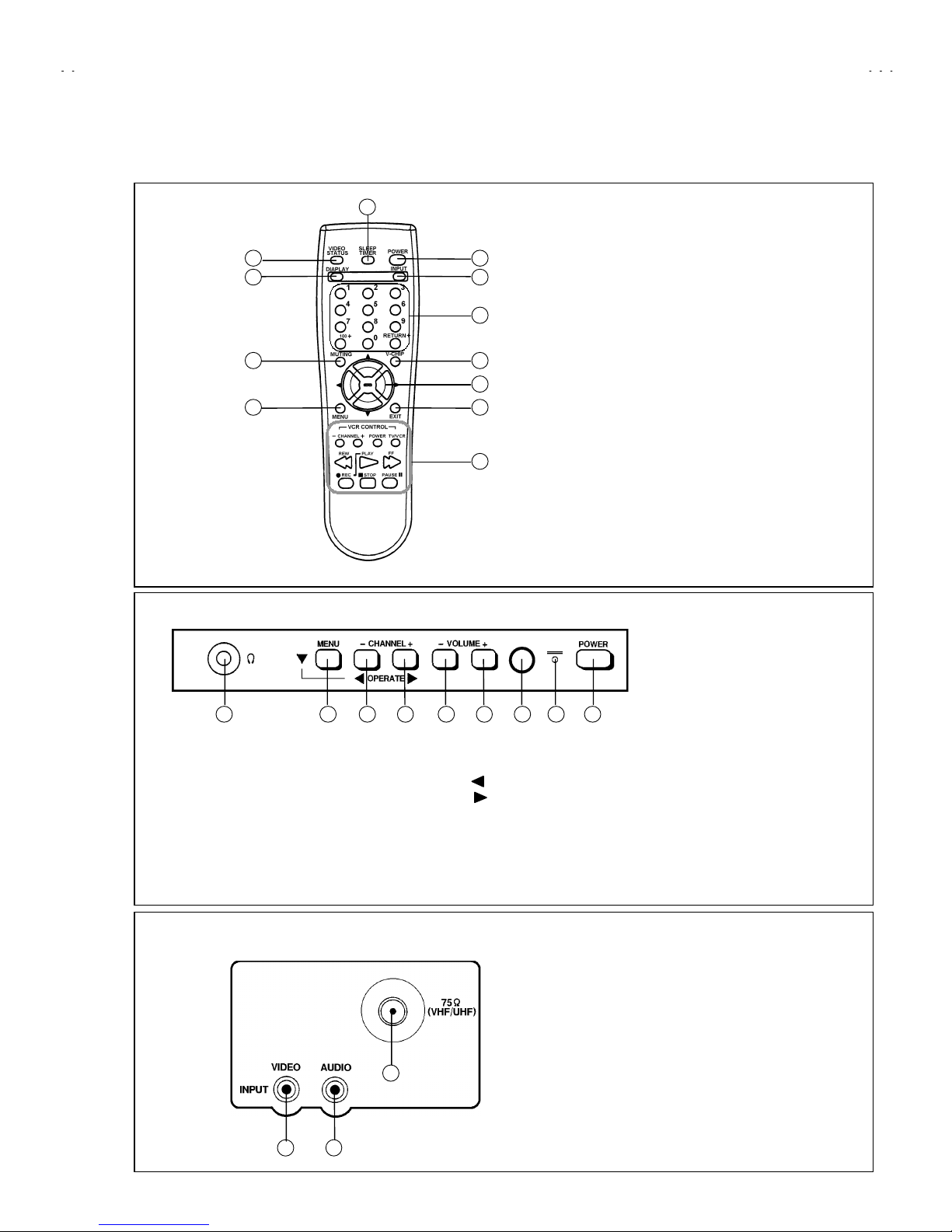
■■■■
REMOTE CONTROL UNIT
■■■■
FRONT PANEL
■■■■
REAR PANEL
①
Headphone terminals
②
MENU button
③
CHANNEL - (Operate ) button
④
CHANNEL + (Operate ) button
⑤
VOLUME - button
⑥
VOLUME + button
⑦
Remocon window
⑧
Indicator lamp (TIMER / POWER)
⑨
POWER
button
①
VIDEO(INPUT) terminal
②
AUDIO(INPUT) terminal
③
Antenna terminal
①
VIDEO STATUS key
②
DISPLAY keys
③
MUTING key
④
MENU key
⑤
POWER key
⑥
INPUT SELECT key
⑦
CHANNEL key
⑧
V-CHIP key
⑨
FUNCTION key
⑩
EXIT key
⑪
SLEEP TIMER key
⑫
VCR CONTROL keys
1 2 3 4 5 6 7 8 9
1 2
3
1
2
3
4
5
6
7
8
9
10
11
12
Page 6

No. 51831
C-N14210
6
SPECIFIC SERVICE INSTRUCTIONS
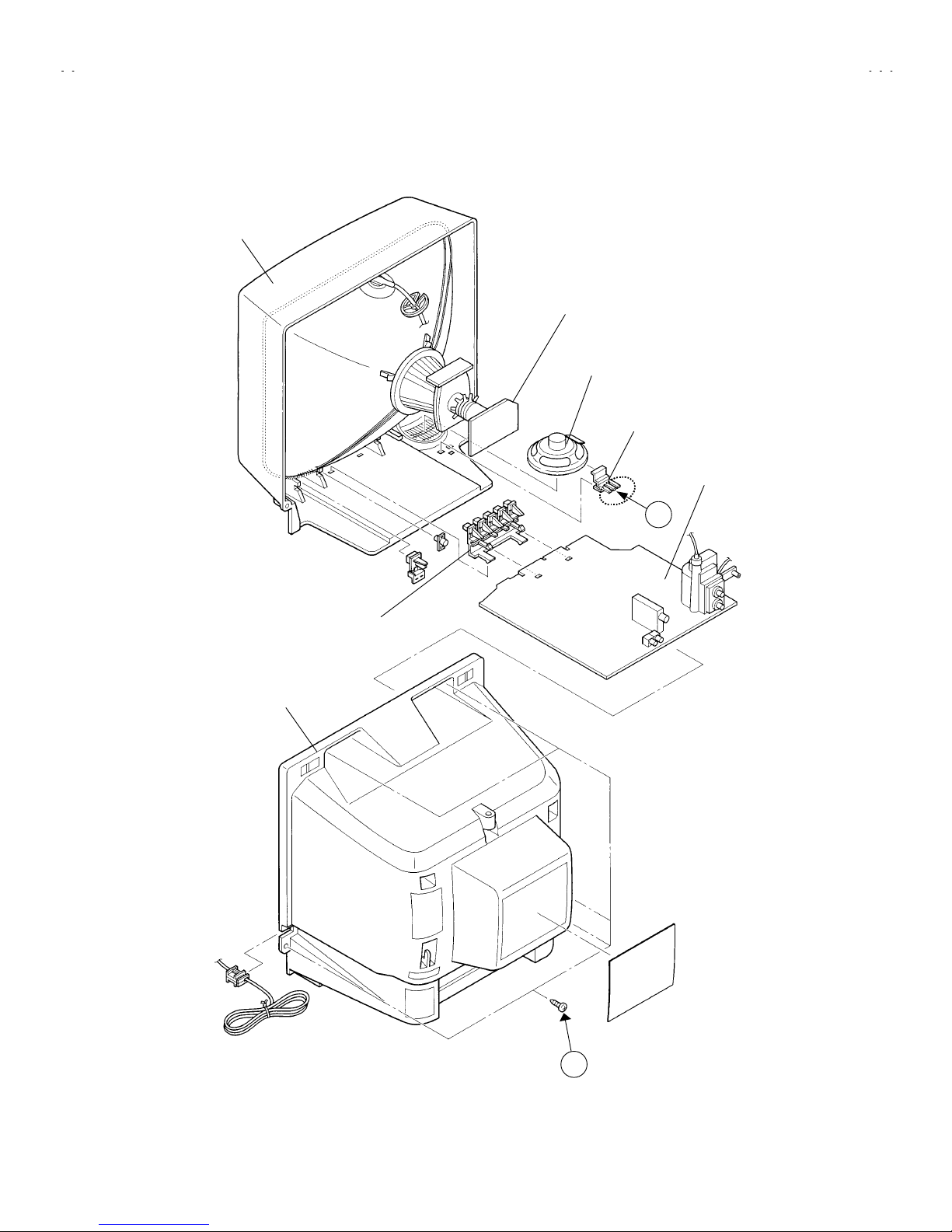
DISASSEMBLY PROCEDURE
REMOVING THE REAR COVER
1. Unplug the power supply cord.
2. Remove the 5 screws marked
!!!!
as shown in Fig.1.
3. Withdraw the REAR COVER toward you.
[CAUTION]
•
When reinstalling the rear cover, carefully push it inward after
inserting the MAIN PWB into the rear cover groove.
REMOVING THE MAIN PW BOARD
1. Slightly raise the both s i d es of t he MAIN PW Board b y han d and
withdraw the MAIN PW Board backward.
(If necessary, t ak e off th e wir e cl am p an d c onnectors , etc .)
REMOVING THE SPEAKER
• After removing the MAIN PW board.
1. B y holding up th e SPEAKER HOLDER mark ed
""""
slightl y and
unlocking the cl aw, the SPEAKER HOLDER c an be removed.
Then you can remove the SPEAKER.
CHECKING THE MAIN PW BOARD
1. To c h eck th e backs id e of the MAIN PW Board.
1) Pull out the MAIN PWB. (Refer to REMOVING THE MAIN
PWB).
2) Erect th e chassis ver tically so th at you can eas ily check t he
backside of the MAIN PW Board.
[CAUTION]
•
When erecting the MAIN PWB, be careful so that there will be no
contact i ng wit h ot her P W Board.
•
Before t ur ning on p ower, m ak e s ure th at t he CRT earth wire and
other connectors are properly connected.
WIRE CLAMPING AND CABLE TYING
1. Be sure clamp the wire.
2. Never remove the cable tie used for tying the wires together.
Should i t b e inad vertent l y removed, be sur e t o t ie the wires with
a new cable tie.
Page 7
No. 51831
C-N14210
7
FRONT CABINET
CRT SOCKET PWB
(Within MA IN PWB)
SPEAKER
REAR COVER
SPEAKER HOLDER
Fig.1
A
B
CONTROL KNOB
MAIN PWB
Page 8
No. 51831
C-N14210
8
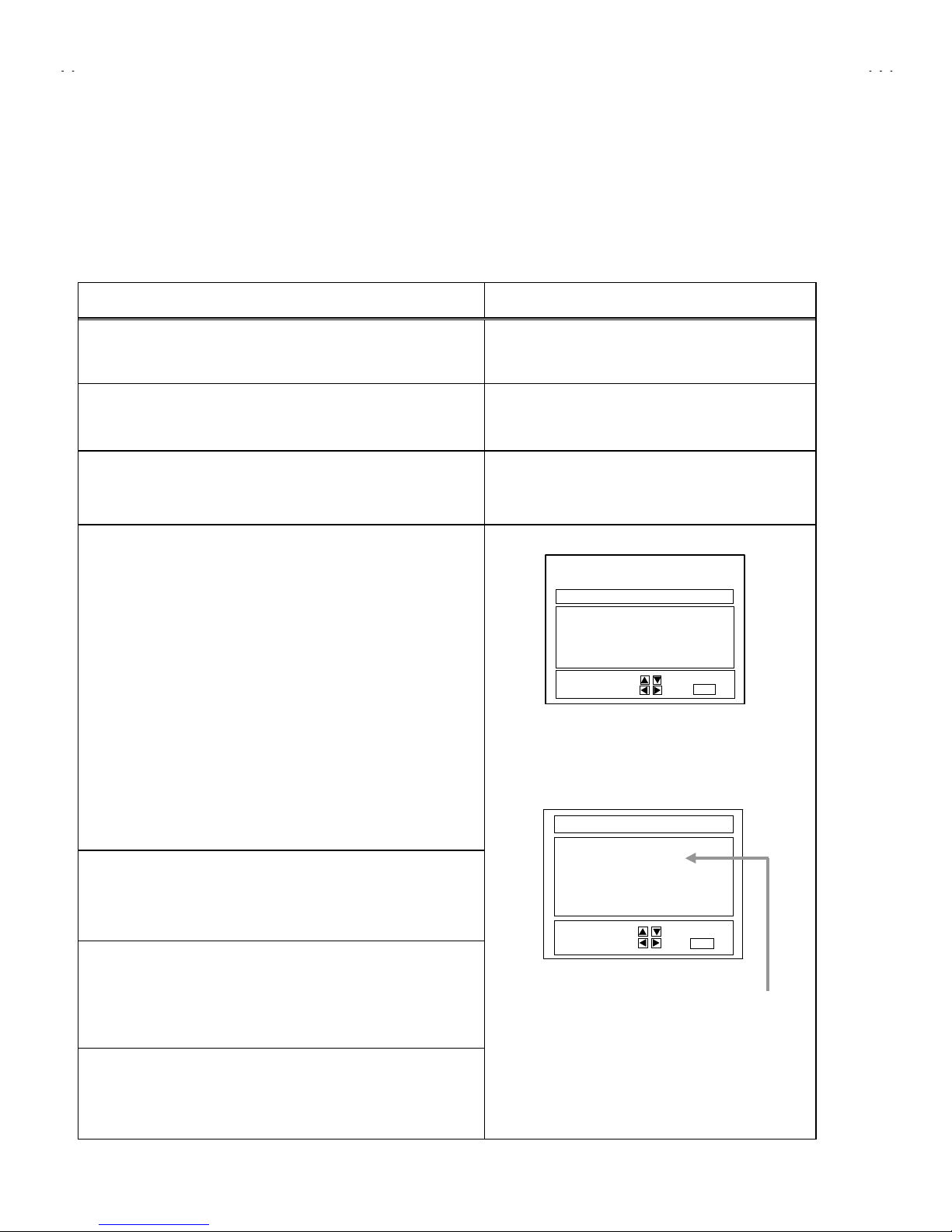
MEMORY IC REPLAC EMENT
1. Memory I C
This model uses a memory IC.
This memory IC stores data for proper operation of the video and deflection circuits.
When replacing, be sure to use an IC containing this (initial value) data.
2. Memory I C replacement procedure
Procedure Screen display
(1) Power off
Switch off th e pow er and disc onn ec t t h e pow er c ord f r om t h e out l et .
(2) Replace the memory IC
Initial val u e mus t b e ent ered into th e new IC .
(3) Power on
Connect the power cord to the outlet and switch on the power.
(4) System constant ch eck and setting
1) Press
SLEEP TIMER
key and, while the ind icati on of “
SLEEP 0 M IN.
”
is being displ ayed, press
DISPLAY
key and
VIDEO STAT US
key on
the remote control unit simultaneously.
2) The SERVICE MENU screen of Fig.1 is displayed.
3) While the S ERVICE MENU is dis played, again simul taneously press
the DISPLA Y and VIDEO S TAT US keys to disp lay the Fi g.2 SYST EM
CONSTANT screen.
4) Refer to t he S YSTEM C ONST ANT t able and ch eck th e settin g it ems.
Where thes e dif fer, s elect t he s etting item w ith th e MENU UP/DO W N
key and adjust the setting with t he MENU LEFT/RIGHT keys. (The
letters of the selected item are displayed in yellow.)
5) After adjusting, release the MENU LEFT/RIGHT key to store the setting
value.
6) Press the EXIT key twice to return the normal screen.
(5) Receive channel setting
Refer to the OPERATING INSTRUCTIONS (USER'S GUIDE) and s et
the receive channels (Channels Preset) as described.
(6) User settings
Check the user setting items according to Table 2.
Where these do not agree, refer to the OP ERATING INSTRUCTIONS
(USER'S GUIDE) and set the items as described.
(7) SERVICE MENU setting
Verify what to set in the SERVICE MENU, and set whatever is
necessary.(Fig.1) Refer to the SERVICE ADJUSTMENT for setting.
SYSTEM CONSTANT
MODEL :
*******
**************
*******
V-CHIP : YES
CAN V-CHIP : YES
********-*****
********-*************-*****
********-*****
SELECT BY EXIT BY
OPERATE BY EXIT
Fig.2
SERVICE MENU
PICTURE
GAME
LOW LIGHT HIGH LIGHT
RF AFC CHK
VCO
(CW)
SELECT BY EXIT BY
OPERATE BY EXIT
Fig.1
Indicate the model name
Page 9

No. 51831
C-N14210
9
TABLE 1 (System Constant setting)
Setting item Setting content Setting value
MODEL Display th e eac h applic ation model C onf or m abl e m od el n ame
V-CHIP YES
CAN V-CHIP YES
TABLE 2 (User setting value)
Setting item Setting value
1. Use remote controller keys
POWER
CHANNEL
CHANNEL PRESET
VOLUME
INPUT (TV/VIDEO)
OFF
CH 02
See OPERATING INSTRUCTIONS.
10
TV
DISPLAY
SLEEP TIMER
VIDEO STATUS
OFF
0
STANDARD
2. Settin g of MEN U
TINT
COLOR
PICTURE
BRIGHT
DETAIL
CENTER
CENTER
CENTER
CENTER
CENTER
NOISE MUTING
SET VIDEO STATUS
ON
ALL CENTER
SET CLOCK
ON/OFF TIMER
LANGUAGE
CLOSED CAPTION
BACK GROUND
Unnecessary to set
NO
SPANISH
OFF
BLACK
AUTO TUNER SETUP
CHANNEL SUMMARY
V-CHIP
SET LOCK CODE
TUNER MODE : AIR
Unnecessary to set
OFF
Unnecessary to set
YES NO
YES NO
Page 10

No. 51831
C-N14210
10
SERVICE ADJUSTMENTS
ADJUSTMENT PREPARATION
1. You can make the necessary adjust ments for this unit with
either the Remote Control Unit or With th e adjustme nt tools
and parts as given below.
2. Adjustment with the Remote Control Unit is made on the
basis of the initial setting values, however, the new setting
values wh ich set the scree n t o its optimu m condition may
differ from the initial settings.
3. Make sure that AC power is turned on correctly.
4. Turn on the power for set and test eq uipment before us e, and
start the adjustmen t procedur es after waitin g at leas t 30 mi nutes.
5. Unless otherwis e specif ied, prep are the m ost suit able rec eption
or input signal for adjustment.
6. N ever touc h any adj ustm ent par ts which are not s pecif ied in t he
list for this adjustment - variable resistors, transformers,
condens er s , etc .
7. Presetting b ef or e ad jus t m ent.
Unless oth erwis e specif ied in th e adjustm ent ins tructi ons, p reset
the following functions with the remote control unit:
VIDEO STATUS STANDARD
TINT/COLOR
PICTURE/BRIGHT
DETAIL
CENTER
ADJUSTMENT EQUIPMENT
1. DC voltmeter (or digital voltmeter)
2. Oscilloscope
3. Signal generator (Pattern generator)[NTSC
]
4. Remote control unit
5. TV audio multiplex s ignal generator.
6. Frequency counter
ADJUSTMENT ITEMS
Adjustment items Adjustment items
B1 POWER SUPPLY
WHITE BALANCE
(Low Light )
IF VCO
WHITE BALANCE
(High Light)
RF. AGC SUB BRIGHT
FOCUS SUB CONTRAST
V. SIZE SUB COLOR
H. POSITION SUB TINT
ADJUSTMENT LOCATIONS
MAIN PWB
S756
FRONT
POWER
INDICATOR LAMP
(TIMER / POWER)
REMOCON
RECEIVER
VOL
+
-
CH
+
-
MENU
IC702
IC701
PW
F901
IC201
T131
T161
DEG
CW
T
TUNER
X
U
C
HV
IC921
TP-E
( )
T522
UPPER : FOCUS
LOWER : SCREEN
TP-91
(B1)
R926
F902
VIDEO
IN
CW
TOP
CRT SOCKET PWB
(SOLDE R SIDE)
(W ithin MAIN PWB ASS'Y )
TP-E
U
T
TP-R
CRT EARTH
(BRAIDED ASS'Y)
E1
AUDIO
IN
TP-12B
S
MEMORY
Page 11

No. 51831
C-N14210
11
BASIC OPERATION SERVICE MENU
1.
TOOL OF SERVICE MENU OPER ATION
Operate the SERVICE MENU with the REMOTE CONTROL UNIT.
2.
SERVICE MENU ITEMS
In general, basic setting (adjustments) items or verifications are performed in the SERVICE MENU.
"
PICTURE
・・・・・・・・・・・・・・・・・・・・
This sets the setting values (adjustment values) of the VIDEO/CHROMA and DEFLECTION circuits.
"
GAME
・・・・・・・・・・・・・・・・・・・・・・・
This is used when the GAME MODE is adjusted.
"
LOW LIGHT
・・・・・・・・・・・・・・・・・・
This sets the setting values (adjustment values) of the WHITE BALANCE circuit.
"
HIGH LIGHT
・・・・・・・・・・・・・・・・・
This sets the setting values (adjustment values) of the WHITE BALANCE circuit.
"
RF AFC CHK
・・・・・・・・・・・・・・・・・
This is used when the IF VCO is adjusted.
[Do not adjust]
"
VCO (CW)
・・・・・・・・・・・・・・・・・・・
This is used when the IF VCO is adjusted.
3. Basic Opera tions of the SER VI C E M EN U
(1) How to enter the SERVICE MENU.
Press
SLEEP TIMER
key and, while the ind ication of “
SLEEP TIM ER 0 MIN.
” is being displayed, press
DISPLAY
key and
VIDEO
STATUS
key on the remote control unit simultaneously to enter the
SERVICE MENU
screen ① shown in the next figure page.
(2) SERVICE MENU screen selection
Press the UP / DOWN key of the MENU to select any of the following items.
(The lett ers of t h e sel ec t ed it ems are disp l ayed in y ell ow .)
●
PICTURE
●
GAME
●
LOW LIGHT
●
HIGH LIGHT
●
RF AFC CHK
●
VCO(CW)
(3) Enter the any setting ( adjustment ) mode
"
PICTURE mode
1) If select any of PIC TU RE item , and th e LE FT / RIG HT key is press ed f r om SER VICE ME NU ( MA IN MENU ) , th e sc reen ② will be
displayed as shown in figure page later.
2) Then the UP / DOWN key is pressed, the PICTURE mode screen ③ is displayed, and the PICTURE setting can be performed.
"
GAME, LOW LIGHT, HIGH LIGHT, RF AFC CHK and VCO (CW) mode
1) If selec t an y of GA ME / LOW LI GHT / HIG H L IGHT / RF AFC C H K / V CO (CW) items, and t h e LEFT / RIG HT ke y is press ed f rom
SERVICE MENU ( MAIN MENU ), the screens ④ ⑤ ⑥ ⑦ ⑧ will be displayed as shown in figure page later.
2) Then the settings or ver ifications c an be perform ed.
Page 12

No. 51831
C-N14210
12
SERVICE MENU
SELECT BY
OPERATE BY
EXIT BY
IT
PICTURE
GAME
LOW LIGHT HIGH LIGHT
RF AFC CHK
VCO
(CW)
EXIT
SELECT BY
EXIT BY
IT
EXIT
BRIGHT
EXIT BY
IT
BRIGHT
EXIT
***
******
***
*** *** ***
*** *** ****** *** ***
*** *** ***
SELECT BY
OPERATE BY
EXIT BY
IT
1. BRIGHT
EXIT
STATUS
***
******
***
********
****************
********
EXIT BY
IT
HIGH LIGHT
EXIT
***
******
***
EXIT BY
IT
TOO HIGH
ABOVE REFERENCE
BELOW REFERENCE
TOO LOW
SYNC : YES
EXIT
SELECT BY
OPERATE BY
EXIT BY
IT
RF AFC
FINE
STATUS
EXIT
①①①①
SERVICE MENU (MAIN MENU)
②②②②
SCREEN
⑥⑥⑥⑥
HIGH LIGHT MODE
***
******
***
⑧⑧⑧⑧
VCO (CW) MODE
④④④④
GAME MODE
SELECT BY
OPERATE BY
EXIT BY
IT
TINT
COLOR
PICTURE
BRIGHT
DETAIL
EXIT
***
******
***
***
******
***
***
******
***
***
******
***
***
******
***
⑦⑦⑦⑦
RF AFC CHK MODE [DO NOT ADJUST]
ON
********
****************
********
⑤⑤⑤⑤
LOW LIGHT MODE
③③③③
PICTURE MODE
***
******
***
Page 13

No. 51831
C-N14210
13
(4) Setting method
1) UP / DOWN key of the MENU
Select the SETTING ITEM.
2) LEFT / RIGHT key of the MENU
Setting(adjust) the SETTING VALUE of the SETTING ITEM.
When th e key is rel eased the SET TING VALUE will b e st ored
(memorized).
3) EXIT key
Return t o the previous sc reen.
(5) Releasing SERVICE MENU
1) After returni ng to the SERVICE M ENU upon completi on of the
setting (adjustment) work, press the EXIT key again.
★
The settin gs f or LOW LIGHT and HIGH LIGHT are d escrib ed in t he
WHITE BALANCE page of ADJUSTMENT .
★
The setting for VCO(CW) are described in the IF VCO page of
ADJUSTMENT.
SELECT BY
OPERATE BY
EXIT BY
IT
1. BRIGHT
EXIT
STATUS
***
******
***
********
****************
********
PICTURE MODE
INITIAL
SETTING VALUE
↓ (Adjust)
SETTING VALUE
SETTING
ITEM
SELECT BY
OPERATE BY
EXIT BY
IT
TINT
COLOR
PICTURE
BRIGHT
DETAIL
EXIT
***
******
***
***
******
***
***
******
***
***
******
***
***
******
***
GAME MOD E
The letter of the selected
Items are dis p layed in yell ow .
Page 14

No. 51831
C-N14210
14
INITIAL SETTING VALUE OF SERVICE MENU
1. Adjustment of the SERVICE MENU is made on the basis of the initial setting values; however, the new s etting values which set the screen
in its optimum condition may differ from the initial setting.
2. Do not change the initial setting values of the setting (Adjustment) items not listed in “ADJUSTMENT”.
""""
PICTURE MODE
#
The four settin g it ems in t he vid eo mode No.7 E XT BR I ., No.8 E XT P IC., No.11 E XT TINT and N o.12 EXT COL . ar e li nk ed to the items in
the TV MODE No.1 BRIG HT, No.2 PICTURE , No.5 TINT and No.6 COLO R, respectivel y. W hen the setting items in the TV mode are
adjust ed, the values i n the set t in g items in the vid eo mode are revis ed au t omaticall y to th e same valu es in the T V m od e. (The initial setting
values given in ( ) are off-set values.)
#
When the f our items ( No.7, 8, 11 and 12) are adjusted in the vid eo mode, the s etti ng values in eac h item are revis ed in d ependently.
No. Setting (Adjustment) items Variable range initial setting value
1. BRIGHT
0 ~ 127
64
2. PICTURE
0 ~ 127
60
3. TV DTL(TV DETAIL)
0 ~ 63
23
4. TV BPF(TV B.P.FILTER) 0 / 1 0
5. TINT
0 ~ 127
57
6. COLOR
0 ~ 127
55
7. EXT BRI.(EXT.BRIGHT)
±
25
(-2)
8. EXT PIC.(EXT.PICTURE)
±
25
(-2)
9. EXT DTL(EXT.DETAIL)
0 ~ 63
25
10. EXT BPF( EXT.B.P.FILTER) 0 / 1 0
11. EXT TINT
±
25
(+9)
12. EXT COL.(EXT.COLOR)
±
25
(+3)
13. V SIZE
0 ~ 63
20
14. V CENT.(V.CENTER)
0 ~ 7
0
15. H POS.(H.POSITION)
0 ~ 31
20
16. OSD HP (OSD H POSITION)
0 ~ 31
23
17. OSD VP (OSD V POSITION)
0 ~ 15
14
18. H AFC 0 / 1 0
19. RF AGC
0 ~ 63
40
20 OSC SEL 0 / 1 0
Page 15

No. 51831
C-N14210
15
"
GAME MODE
Setting (Adjustment) item Variable range initial setting value
TINT
±
20
±
0
COLOR
±
20
±
0
PICTURE
±
20
-10
BRIGHT
±
20 -2
DETAIL
±
15
+10
"
LOW LIGHT MODE
Setting (Adjustment) item Variable range initial setting value
R CUTOFF
G CUTOFF
B CUTOFF
0 ~ 255
0 ~ 255
0 ~ 255
20
20
20
"
HIGH LIGHT MODE
Setting (Adjustment) item Variable range initial setting value
G DRIVE
B DRIVE
0 ~ 255
0 ~ 255
128
128
"
RF AFC CHECK MODE
Setting (Adjustment) item Variable range initial setting value
RF AFC
FINE
ON / OFF
-77 ~ +77
ON
±××
DO NOT
ADJUST
Page 16

No. 51831
C-N14210
16
ADJUSTMENTS
B1 POWER SUPPLY
Item
Measuring
instrument
Test point Adjustment part Description
Check of
B1 POWER
SUPPLY
DC Voltmeter TP-91 (B1)
TP-E(
""""
)
1. Receive a black- and-white signal.
2. Connect the DC Volt m eter to TP- 91 (B1) and TP-E(
""""
) (See the
page of Adjustment Locations).
3. Confirm that the voltage is DC134V
ADJUSTMENT OF VIDEO / DEF. CIRCUIT
Item
Measuring
instrument
Test point Adjustment part Description
IF VCO
adjustment
Signal
generator
CW TRANSF. (T131)
[VCO(CW)] MODE
"
Und er n orm al c onditions, no adjustm ent is r equ ired.
1. Receive a NTSC broadcast. (use channels without offset
frequency).
2. Select the VCO(CW) mode from the SERVICE MENU.
3. Confirm the color change (yellow) from “TOO HIGH” to “TOO
LOW”by CW TRANSF. and “SYNC : YES” being shown on
the screen. Then, adjust CW TRANSF. until “BELOW
REFERENCE” mark turns yellow and confirm again “ SYNC :
YES” being s hown on the sc r een.
RF. AGC
adjustment
No.19 RF AGC
1. Rec eive a br oadcast.
2. Select “No.19 RF AGC” of the PICTURE MODE.
3. Press the MUTE key and turn off color.
4. With th e MENU LEFT key, g et noise in t he screen p icture. ( 0
side of sett in g value)
5. Press the MENU RIGHT key an d stop when no ise dis appears
from the screen.
6. Change to other channels and make sure that there Is no
irregularity.
7. Press the MUTE key and get color out.
FOCUS
adjustment
Signal
generator
FOCUS VR
[In HVT]
1. Receive a crosshatch signal.
2. While looking at the screen, adjust FOCUS VR so that the
vertic al and hor i z ont al lines will be clear and in f in e det ail.
3. Make sure that the picture is in focus even when the screen gets
darkened.
+2V
-2.5V.
EXIT BY
IT
TOO HIGH
ABOVE REFERENCE
BELOW REFERE NCE
TOO LOW
SYNC : YES
EXIT
YELLOW
Page 17

No. 51831
C-N14210
17
Item
Measuring
instruments
Test point Adjustment pa rt Description
V.SIZE
Adjustment
Signal
generator
No.13 V.SIZE
1. Receive a crosshatch signal.
2. Select No.13 V SIZE in the PICTURE MODE.
3. Set the initial setting value of No.13 V SIZE with the LEFT / RIGHT
key of the MENU.
4. Adjust No.13 V SIZE until the vertical screen size is 92%.
H.POSITION
Adjustment
Signal
generator
No.15 H PO S .
1. Receive a crosshatch signal.
2. Select the No.15 H POS. of the PICTURE MODE.
3. Set the i nitial s etti ng value of the No.1 5 H POS . with th e LEFT /
RIGHT key of the MENU.
4. Adjust the No.15 H POS. until the screen will be horizontally
centered.
Screen size
Picture size 100%
Screen
size
92%
Picture
size
100%
Page 18

No. 51831
C-N14210
18
Item
Measuring
instruments
Test point A djustment p art Descri ption
WHITE
BALANCE
(Low Light)
Adjustment
Signal
generator
BRIGHT
R. CU TOFF
G. CUTOFF
B. CU TOFF
SCREEN VR
[In HVT]
1. Receive a blac k-and- w hit e si gn al. ( Color off)
2. Select the【LOW LIGHT】MODE from the SERVICE MENU.
3. Set the initial setting value of BRIGHT with the LEFT / RIGHT
key of the remote control unit.
4. S et the init i al s etting val u e of R CU TO FF, G CUT OF F an d B
CUTOFF with the ④ to ⑨ key of the remote control unit.
5. Displ ay a si ngle h oriz ontal li ne b y pr essing t he ①key of the
remote control unit.
6. Turn the screen VR all the way to the left.
7. T urn the screen VR graduall y to the right f rom the left until
either one of the red, blue or green colors appears faintly.
8. Adjus t the two c ol ors which di d not appear until the sin gle
horizontal line that is displayed bec omes white using the
④
to ⑨ keys of the remot e c ontrol unit.
9. T urn the sc reen VR to wh ere th e sin gl e h orizon tal l in e gl ows
faintly.
10. Press the ② key to return to the regular screen.
*
The ③ EXIT key is the cancel key for the WHITE
BALANCE.
WHITE
BALANCE
(High Light)
Adjustment
Signal
generator
G. DRIVE
B. DRI V E
1. Receive a black-and-whit e si gnal. (Col or off)
2. Select the【HIGH LIGHT】MODE in the SERVICE MENU.
3. Set the initial s etting val u e of G DRIV E and B DRIVE w it h t h e
⑤, ⑥, ⑧
and ⑨ keys of the remote control unit.
4. Adjust the scr een until it bec om es white us i ng the ⑤, ⑥,
⑧
and ⑨ keys of the remote control unit.
*
The ③ (EXIT) key is the cancel key for the WHITE
BALANCE.
[LOW LIGHT] MODE
BRIGHT
EXIT BY
IT
BRIGHT
EXIT
***
******
***
***
******
***
***
******
***
***
******
***
1 2 3
6
987
54
REMOTE CONTROL UNIT
H.LINE ON E X ITH.LINE OFF
R CUTOFF B CUTOFFG CUTOFF
R CUTOFF B CUTOFFG CUTOFF
BRIGHT
G CUTOFF
B CUTOFF
R CUTOFF
[HIGH LIGHT] MODE
EXIT BY
IT
HIGH LIGHT
EXIT
***
******
*** ***
******
***
G DRIVE
B DRIVE
Remote Control Unit
①
key : H.LINE ON
②
key : H.LINE OFF
③
key : EXIT
⑤
key : G DRIVE
▲
⑥
key : B DRIVE
▲
⑧
key : G DRIVE
▼
⑨
key : B DRIVE
▼
Page 19

No. 51831
C-N14210
19
Item
Measuring
instruments
Test point A djustment p art Descri ption
SUB
BRIGHT
Adjustment
No.1 BRIGHT
1. Receive a br oadcast.
2. Select No.1 BRIGHT of the PICTURE MODE.
3. S et the initial setting valu e of the No.1 BRIGHT with th e LEFT
/ RIGHT key of the MENU.
4. I f the br i gh tn ess is not best with th e i nitial sett i ng val u e, m ak e
fine adjustment of the No.1 BRIGHT until you get the optimum
brightness.
SUB
CONTRAST
Adjustment
No.2 PICTURE
1. Receive a broadcas t.
2. Select No.2 PICTURE of the PICTURE MODE.
3. Set the initial setting value of the No.2 PICTURE with the
LEFT / RIGHT key of the MENU.
4. If the contr ast is not best with the in itial setting value, mak e
fine adjustment of the No.2 PICTURE until you get the
optimum contrast.
SUB
COLOR
Adjustment
No.6 COL OR
1. Receive a br oadcast.
2. Select No.6 COLOR of the PICTURE MODE.
3. Set the initial setting value of the No.6 COLOR with the
LEFT / RIGHT key of the MENU.
4. If the color is not best with the initi al settin g value, m ake fine
adjustment of the No.6 COLOR until you get the optimum
color.
SUB TINT
Adjustment
No.5 TINT
1. Receive a broadcas t.
2. Select No.5 TINT of the PICTURE MODE.
3. Set the initi al setting val ue of the No.5 TIN T with the LEFT /
RIGHT key of the MENU.
4. If the tint is n ot best with th e in itial setting value, mak e fine
adjust m ent of t h e No. 5 TIN T until you get th e optimum ti nt.
Page 20

No. 51831
C-N14210
20
PURITY, CONVERGENCE
PURITY ADJUSTMENT
1. Demagnetize CRT with the demagnetizer.
2. Loosen the retainer screw of the deflection yoke.
3. Remove the w ed g es.
4. I nput a green r aster signal fr om the sign al gener ator, and t urn
the screen to green raster.
5. Move the defl ec tion yoke bac k w ard.
6. Brin g the long l ug of the purit y magnets on the sh ort lug an d
position them horizontally. (Fig.2)
7. Adjust the g ap between t w o l ugs s o t h at the GREEN RAST ER
will come into the center of the screen. (Fig.3)
8. Move the defl ec tion yoke forw ar d, and fix the position of the
deflection yoke so that the whole screen will become green.
9. Insert the wedge to the top side of the deflection yoke so that it
will not move.
10. Input a crosshatch signal.
11. Verify that the screen is hori z ont al.
12. Inp ut red and blu e raster si gnals, and make su re that pur ity is
properl y adjusted.
CRT
WEDGE
DEFLECTION
YOKE
P / C
MAGNETS
P
46
PURITY MAGNETS
Long lug
Short lug
Bring the long lug over the short lug
and position them horizontally.
(
FRONT VIEW
)
GREEN RASTER
CENTER
P : PURITY MAGNET
4 : 4 POLES
(con vergence m agn ets )
6 : 6 POLES
(con vergence m agn ets )
$
P/C M AGNE TS
Fig.1
Fig.3
Fig.2
Page 21

No. 51831
C-N14210
21
STATIC CONVERGENCE ADJUSTMENT
1. Input a crosshatch signal.
2. Using 4- pole converg ence magnet s, overlap the r ed and blue
lines in the center of the screen (Fig.1) and turn them to
magenta (red/blue).
3. Using 6-pole convergence magnets, overlap the
magent a(red/bl ue) and green lines in th e center of th e screen
and turn them to white.
4. Repeat 2 and 3 abov e, and make b est c on vergenc e.
DYNAMIC CONVERGENCE ADJUSTMENT
1. Move the deflec tion yok e up an d d own an d over lap th e lines in
the periphery. (Fig. 2)
2. Move the deflection yoke left to right and overlap the lines in the
periphery. (Fig. 3)
3. Repeat 1 and 2 abov e, and make b est c on vergenc e.
●
After adjus tment, fi x the w ed g e at the or i gi nal positi on.
Fasten the retainer screw of the deflection yoke.
Fix the 6 m agnets with glue.
(FRONT VIEW)
GREEN
(FRONT VIEW)
BLUE
RED
BLUE
GREEN
RED
RED
GREEN
BLUE
GREEN RED
BLUE
GREEN
(FRONT VIEW)
BLUE
RED
BLUE
GREEN
RED
RED
GREEN
BLUE
GREEN
RED
BLUE
Fig.3
Fig.2
Fig.1
Page 22

No. 51831
C-N14210
22
HOW TO CHECK THE HIGH VOLTAGE HOLD DOWN CIRCUIT
1. HIGH VOLTAGE HOLD DOWN CIRCUIT
After rep airing the high v oltage hold d ow n circuit sh ow n in Fi g. 1.
This circuit shall be checked to operate correctly.
2. CHECKING OF THE HIGH VOLTAGE HOLD DOWN CIRC UIT
(1) Turn the POWER SW ON.
(2) As shown in Fig. 1, set the resistor (between X connector 1 & 3 ).
(3) Make sure that the screen picture disappears.
(4) Temp or ar il y un plug the pow er c ord.
(5) Remove the resistor (between X connector 1 & 3 ).
(6) Again plug the power cord, make sure that the normal picture is displayed on the screen.
Fig. 1
4
HVT
CONNECTOR
RESISTOR
14.46k
Ω±
Ω±Ω±
Ω±
1% 1/4W
HEATER
R562
D561
R561
X
C561
R563
D562
3 2 1
Q561
12V
D563
Q562
Q951
D958
R953
12V
RY901
POWER
ON OFF
C562
R564
Page 23

No. 51831
C-N14210
23
SELF CHECK FUNCTIONS
1. Outline
This model has self ch eck func t i ons gi ven below. When a malf unc ti on has been d etected, t h e POWER is turn ed off and t h e L ED flashes to
inform of the failure. The malfunction is detected by the signal input state of the control line connected to the microcomputer.
2. Self check items
Check item Details of detect ion Method of detection State of malfunct ion
CRT NECK protector
Also detected if the
power su pply lin e output
from the HVT (High
voltage Transformer) has
shorted with the ground.
W hen th e ve rt ic al ci rcu it Scorrection capacitor C427
is shorted, detect the
potenti al drop of the C427,
and prevent the burn
damage to the CRT NECK.
(Grounding of shorting of
the power supply output
from the HVT to the vertical
circuit, and the smal l sign al
power supply is also
detected.)
The microcomputer detects at 1second intervals.
If NG is detected for more than 1
ms, a malfu nc ti on is interpreted.
When a malfunction has been
detected, the POWER is turned
off. While the POWER is being
turned off, the power key of the
remote contr oller is not op er ation al
until the power code is taken out
and put in ag ain.
3. Self check indicating function
The self-c heck funct ion begins detecti on about 5 s econds after
power is supplied.
In the event a malfunction is detected, the power is cut off
immediately.
At this time, the ON-TIMER LED flashes to inform of the
malfunction.
[ON-TIMER LED indication]
The ON-TIMER LED flashes at 0.5 seconds intervals.
POWER
Supplied
After about
5 seconds
Malfunction
is detected
POWER OFF
Flashin
g
ON-TIMER LED
Start of
detection
Page 24

No. 51831
C-N14210
24
REPLACEMENT OF CHIP COMPONENT
!
CAUTIONS
1. Avoid heating for more than 3 seconds.
2. Do not rub the electrodes and the resist parts of the pattern.
3. When removing a chip part, melt the solder adequately.
4. Do not reus e a chip part after rem ovi ng it.
!
SOLDERING IRON
1. U s e a high ins ul at i on s old er in g iron with a thin p ointed end of it.
2. A 30w soldering iron is recommended for easily removing parts.
ADJUSTMENTS
!
REPLACEMENT STEPS
1.
How to remove Chip parts
%
Resistor s, ca pa ci t or s, et c.
(1) As shown in the figure, push the part with tweezers and
alternat ely melt th e s old er at eac h en d.
(2) Shift with tw eez er s an d rem o ve t h e ch ip p ar t.
%
Transistors, diodes, variable resistors, etc.
(1) Apply extra solder to each lead.
(2) As shown in the figure, push the part with tweezers and
alternat ely melt th e s old er at eac h l ead . Shift and remove th e
chip part.
Note : After rem oving the par t, rem ov e r em a in ing solder from the
pattern.
2. How t o i nst al l Chip p arts
%
Resistor s, ca pa ci t or s, et c.
(1) Apply solder to the pattern as indicated in the figure.
(2) G r asp the chip p art wit h t w e ez ers and plac e it on the sol d er.
Then heat an d m elt the solder at b oth en ds of t h e chip part.
%
Transistors, diodes, variable resistors, etc.
(1) Apply solder to the pattern as indicated in the figure.
(2) Grasp the chip part with tweezers and place it on the solder.
(3) First solder lead
A
as indicated in the figure.
(4) Then solder leads
B
and C.
SOLDER
SOLDER
A
B
C
A
B
C
Page 25

N14210S-MEM #3
4
VP 0108
DP3051
V
ICTOR COMPANY OF JAPAN, LIMITED
HOME AV NETWORK BUSINESS UNIT 12, 3-chome, Moriya-cho, Kanagawa-ku, Yokohama, Kanagawa-prefecture, 221-8528, Japan
 Loading...