

Page 1
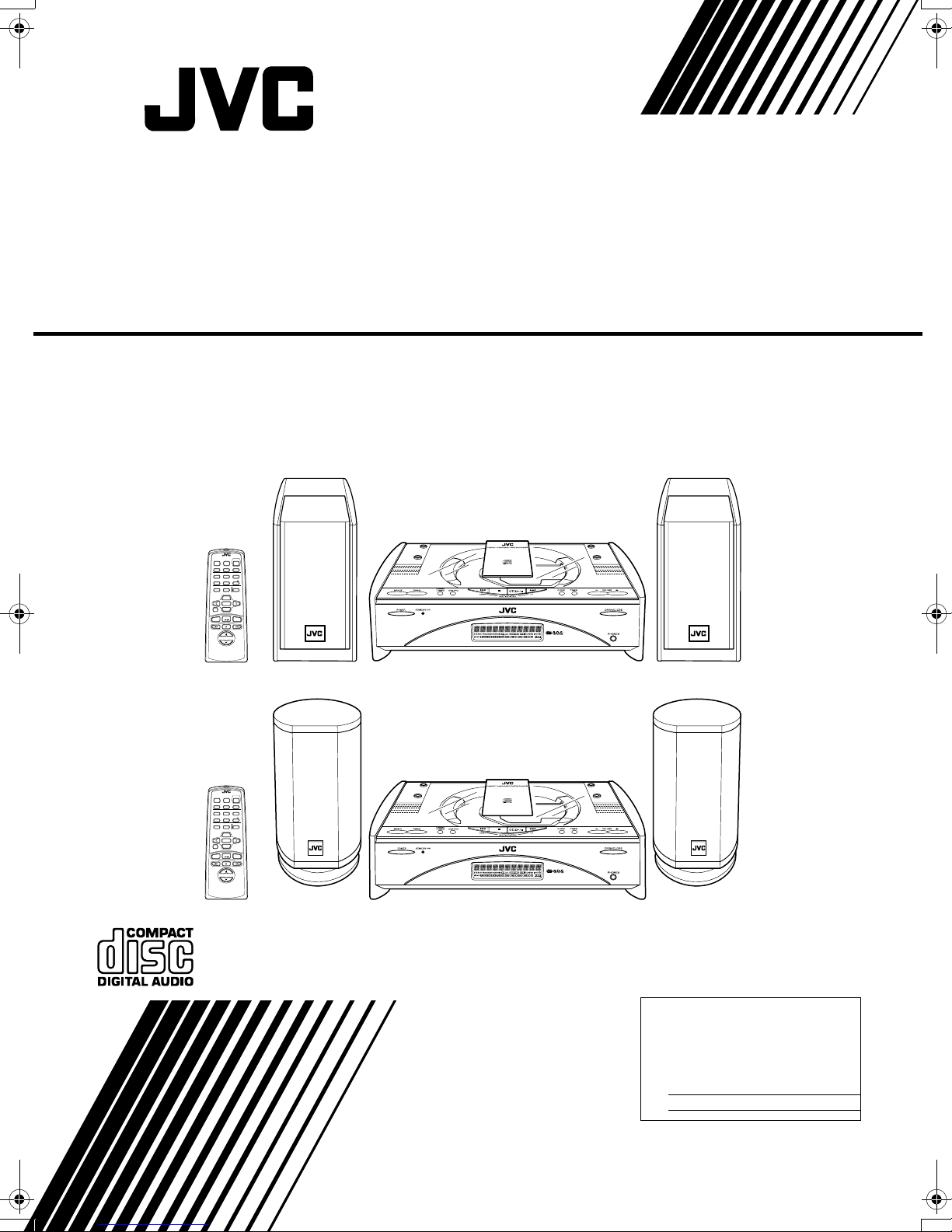
COMPACT COMPONENT SYSTEM
FS-SD550/FS-SD770/FS-SD990
Consist of CA-FSSD550 and SP-FSSD550
Consist of CA-FSSD770 and SP-FSSD770
Consist of CA-FSSD990 and SP-FSSD990
REMOTE CONTROL
POWER
DIMMER SLEEP
AUTO
DISPLAY FM MODE
PRESET
PROGRAM
REPEATRANDOM
DOOR
CD
AHB PRO
SLIDE
BASS TREBLE CANCEL
UP
SET
DOWN
FADE MUTING
CD
MD/AUX FM / AM
VOLUME
FS-SD550
REMOTE CONTROL
POWER
DIMMER SLEEP
AUTO
DISPLAY FM MODE
PRESET
PROGRAM
REPEATRANDOM
DOOR
CD
AHB PRO
SLIDE
BASS TREBLE CANCEL
UP
SET
DOWN
FADE MUTING
CD
MD/AUX FM / AM
VOLUME
FS-SD770, FS-SD990
INSTRUCTIONS
For Customer Use:
Enter below the Model No. and Serial No.
which are located either on the rear, bottom or side of the cabinet. Retain this
information for f utur e reference.
Model No.
Serial No.
GNT0008-001A
[J]
Page 2
Warnings, Cautions and Others
CLASS 1
LASER PRODUCT
CAUTION
RISK OF ELECTRIC
SHOCK
DO NOT OPEN
IMPORTANT FOR LASER PRODUCTS
REPRODUCTION OF LABELS
1. CLASSIFICATION LABEL, PLACED ON EXTERIOR SURFA CE
CAUTION: TO REDUCE THE RISK OF ELECTRIC SHOCK
DO NOT REMOVE COVER (OR BACK)
REFER SERVICING TO QUALIFIED SERVICE PERSONNEL.
NO USER SERVICEABLE PARTS INSIDE
The lightning flash with arrowhead symbol,
within an equilateral triangle is intended to
alert the user to the presence of uninsulated
“dangerous voltage” within the product’s enclosure that may be of sufficient magnitude to
constitute a risk of electric shock to persons.
The exclamation point within an equilateral triangle is intended to alert the user to the presence of important operating and maintenance
(servicing) instructions in the literature accompanying the appliance.
For U.S.A
This equipment has been tested and found to comply with the
limits for a Class B digital device, pursuant to Part 15 of the
FCC Rules. These limits are designed to provide reasonable
protection against harmful interference in a residential installation. This equipment generates, uses, and can radiate radio
frequency energy and, if not installed and used in accordance
with the instructions, may cause harmful interference to radio
communications. However, there is no guarantee that interference will not occur in a particular installation. If this equipment
does cause harmful interference to radio or television reception, which can be determined by turning the equipment off and
on, the user is encouraged to try to correct the interference by
one or more of the follo wing me asures:
– Reorient or relocate the receiving antenna.
– Increase the separation between the equipment and
receiver.
– Connect the equipment into an outlet on a circuit different
from that to which the receiver is connected.
–Consult the dealer or an experienced radio/TV technician
for help.
2. WARNING LABEL, PLACED INSIDE THE UNIT
CLASS 1 LASER PRODUCT
1.
DANGER:
2.
Invisible laser radiation when open and interlock
failed or defeated. Avoid direct exposure to beam.
CAUTION:
3.
Do not open the top cover. There are no user serviceable parts inside the unit; leave all servicing to qualitied
service personnel.
CAUTION
To reduce the risk of electrical shocks, fire, etc.:
Do not remove screws, covers or cabinet.
1
Do not expose this appliance to rain or moisture.
2.
CAUTION
■■■■ About the Internal Cooling Fan
This unit includes an internal cooling fan, so as to allow for
high-power operation within a small space.
This fan comes on when the sound level is set high, and ma y
also come on even at lo w sound levels if the internal temperature rises. To ensure effectiv e fan operation, please leave at
least 15cm clearance between the rear of the unit and the
wall, and at least 1cm clearance on each side of the unit.
Caution — POWER switch!
Disconnect the mains plug to shut the power off completely.
The POWER switch in any position does not disconnect the
mains line. The power can be remote controlled.
WARNING: TO REDUCE THE RISK OF FIRE
OR ELECTRIC SHOCK, DO NOT EXPOSE
THIS APPLIANCE TO RAIN OR MOISTURE.
G-1
Page 3
Introduction
Thank you for purchasing the JVC Compact Component System.
We hope it will be a valued addition to your home, giving you years of enjoyment.
Be sure to read this instruction manual carefully before operating your new stereo system.
In it you will find all the information you need to set up and use the system.
If you have a query that is not answered by the manual, please contact your dealer.
Features
Here are some of the things that make your System both powerful a nd simple to use.
■ The controls and operations have been redesigned to make them very easy to use, freeing you to
just enjoy the music.
• With JVC’s COMPU PLAY you can turn on the System and automatically start the Radio or
CD Player with a single touch.
■ The System incorporates Active Hyper Bass PRO circuitry to faithfully reproduce low frequency
sounds.
■ A 45-station preset capability (30 FM and 15 AM) in addition to auto-seek and manual tuning.
■ CD options that include repeat, random and program play.
■ Timer functions; Daily Timer and Sleep Timer.
■ You can connect various external units, such as an MD recorder.
■ The system can play CD-R and CD-RW after they have been finalized.
■ You can play back your original CD-R or CD-RW recorded in Music CD format. (However they may not be p layed back
depending on their characteristics or recording conditions.)
How This Manual Is Organized
• Basic information that is the same for many different functions - e.g. setting the volume - is given in the section
‘Basic Operations’, and not repeated under each function.
• The names of buttons/controls and display messag es are written in all capital letters: e.g. FM/AM, “NO DISC”.
• System functions are written with an initial capital letter only: e.g. Normal Play.
Use the table of contents to look up specific information you requi re.
We have enjoyed making this manual for you, and hope it serves yo u in enjoying the many features built into your System.
WARNINGS
• DO NOT PUT ANYTHING ON THE TOP COVER. IF THE SYSTEM IS OPERATED WITH SOMETHING
PUT ON THE TOP COVER, IT WILL BE DAMAGED WHEN YOU TRY TO OPEN THE TOP COVER.
• NEVER REMOVE THE TOP COVER FROM THE UNIT. SERIOUS INJURY MAY OCCUR IF THE SYSTEM IS OPERATED WITHOUT THE TOP COVER.
IMPORTANT CAUTIONS
Installation of the System
1
• Select a place which is level, dry and neither too hot nor too cold. (Between 5°C and 35°C or 41°F and 95°F.)
• Leave sufficient distance between the System and a TV.
• Do not use the System in a place subject to vibrations.
Power cord
2
• Do not handle the power cord with wet hands!
• Some power is always consumed as long as the power cord is connected to the wall outlet.
• When unplugging the System from the wall outlet, always pull the plug, not the power cord.
Malfunctions, etc.
3
• There are no user serviceable parts inside. In case of system failure, unplug the power cord and consu lt your dealer.
• Do not insert any metallic object into the System.
• Do not insert your hand between the Top Cover and the main body when the Top Cover is being closed.
1
Page 4

Table of Contents
Introduction........................................................................................................1
Features ......................................................................................................................................1
How This Manual Is Organized.................................................................................................1
WARNINGS ..............................................................................................................................1
IMPORTANT CAUTIONS .......................................................................................................1
Getting Started...................................................................................................3
Accessories.................................................................................................................................3
How To Put Batteries In the Remote Control............................................................................3
Using the Remote Control..........................................................................................................3
Connecting the FM Antenna......................................................................................................4
Connecting the AM Antenna......................................................................................................5
Connecting the Speakers............................................................................................................6
Connecting a Subwoofer............................................................................................................7
Connecting External Equipment................................................................................................7
Connecting an MD Recorder, etc (Digital Output)....... .... .... .... ......................................... .... ....7
Connecting the AC Power Cord.................................................................................................8
COMPU Play..............................................................................................................................8
Automatic Power On..................................................................................................................8
Basic Operations ....................................................................... ..... .... ...............9
Turning the Power On and Off...................................................................................................9
Adjusting the Brightness (DIMMER)........................................................................................9
Adjusting the Volume................................................................................................................9
Fade-out Muting (FADE MUTING)........................................................................................10
Reinforcing the Bass Sound (AHB PRO)................................................................................10
Tone Control (BASS/TREBLE)...............................................................................................10
Showing the Time (CLOCK/DISPLAY).................................................................................10
Sliding the Top Cover (DOOR SLIDE)...................................................................................10
Using the Tuner................................................................................................11
Tuning In a Station...................................................................................................................11
Presetting Stations....................................................................................................................12
Auto Presetting.........................................................................................................................12
To Change the FM Reception Mode........................................................................................12
Using the CD Player.........................................................................................13
To Insert a CD..........................................................................................................................13
To Unload a CD.......................................................................................................................14
Basics of Using the CD Player-Normal Play...........................................................................14
Programming the Playing Order of the Tracks........................................................................14
Random Play............................................................................................................................15
Repeating Tracks......................................................................................................................15
Using External Equipments ............................................................................16
Listening to External Equipment..... .... ........................................................................ .............16
Recording the System’s Source to External Equipment ..........................................................16
Using the Timers..............................................................................................17
Setting the Clock... .... ... ...................................... ...................................... ................................17
Setting the Daily Timer................................................................................... .........................17
Setting the SLEEP Timer.........................................................................................................19
Care And Maintenance ................................................................... .... .............20
Troubleshooting...................... ..... .... .... ...................................... ..... .................21
Specifications.................. .... .... ....................................... .... ..............................22
2
Page 5
Getting Started
Accessories
Make sure that you have all of the following items, which are supplied with the System.
Power Cord (1)
AM Loop Antenna (1)
Remote Control (1)
Batteries (2)
FM Wire Antenna (1)
Speaker Cords (2)
If any of these items are missing, contact your dealer immediately.
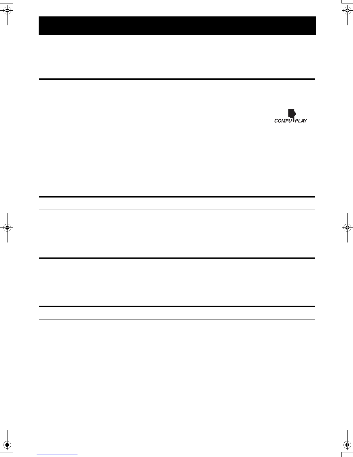
How To Put Batteries In the Remote Control
Match the polarity (+ and –) on the batteries with the + and – markings in the battery compartment.
R6P(SUM-3)/AA(15F)
CAUTION:
• Handle batteries properly.
■ To avoid battery leakage or explosion:
• Remove batteries when the Remote Control will not be used for a long time.
• When you need to replace the batteries, replace both batteries at the same time with new ones.
• Do not use an old battery with a new one.
• Do not use different types of batteries together.
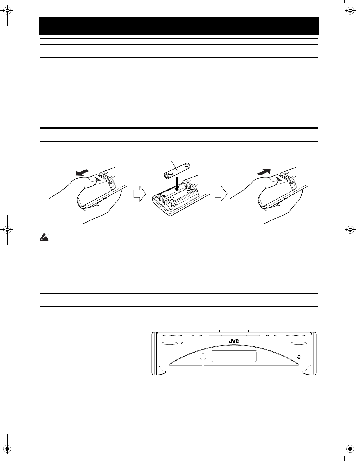
Using the Remote Control
The Remote Control makes it easy to use many of the functions of the System from a distance of up to 7m (23 feet) away.
You need to point the Remote Control at the remote sensor on the System’s front panel.
STANDBY/ONPOWER OPEN/CLOSE
PHONES
Remote sensor
3
Page 6

Getting Started
Getting Started
Getting StartedGetting Started
CAUTION:
• Make all connections before plugging the System into an AC power outlet.
Connecting the FM Antenna
Rear Panel of the Unit
SUB WOOFER
CD DIGITAL OUT
AM LOOP
OUT IN
MD
/
ANTENNA
AM EXT FM(75
COAXIAL
AUX
)
Using the Supplied Wire Antenna
FM wire antenna (supplied)
Using the Coaxial Type Connector
(Not Supplied)
A 75-ohm antenna with coaxial type connector should be
connected to the FM 75-ohm COAXIAL terminal.
SPEAKERS IMPEDANCE 4 16
R
AC IN
L
• Before attaching a 75 ohm coaxial lead (the kind with a
round wire going to an outdoor antenna), disconnect the
supplied FM Wire Antenna.
If reception is poor, connect the outdoor antenna.
Coaxial cable
4
FM outdoor
antenna
(Not supplied)
Page 7
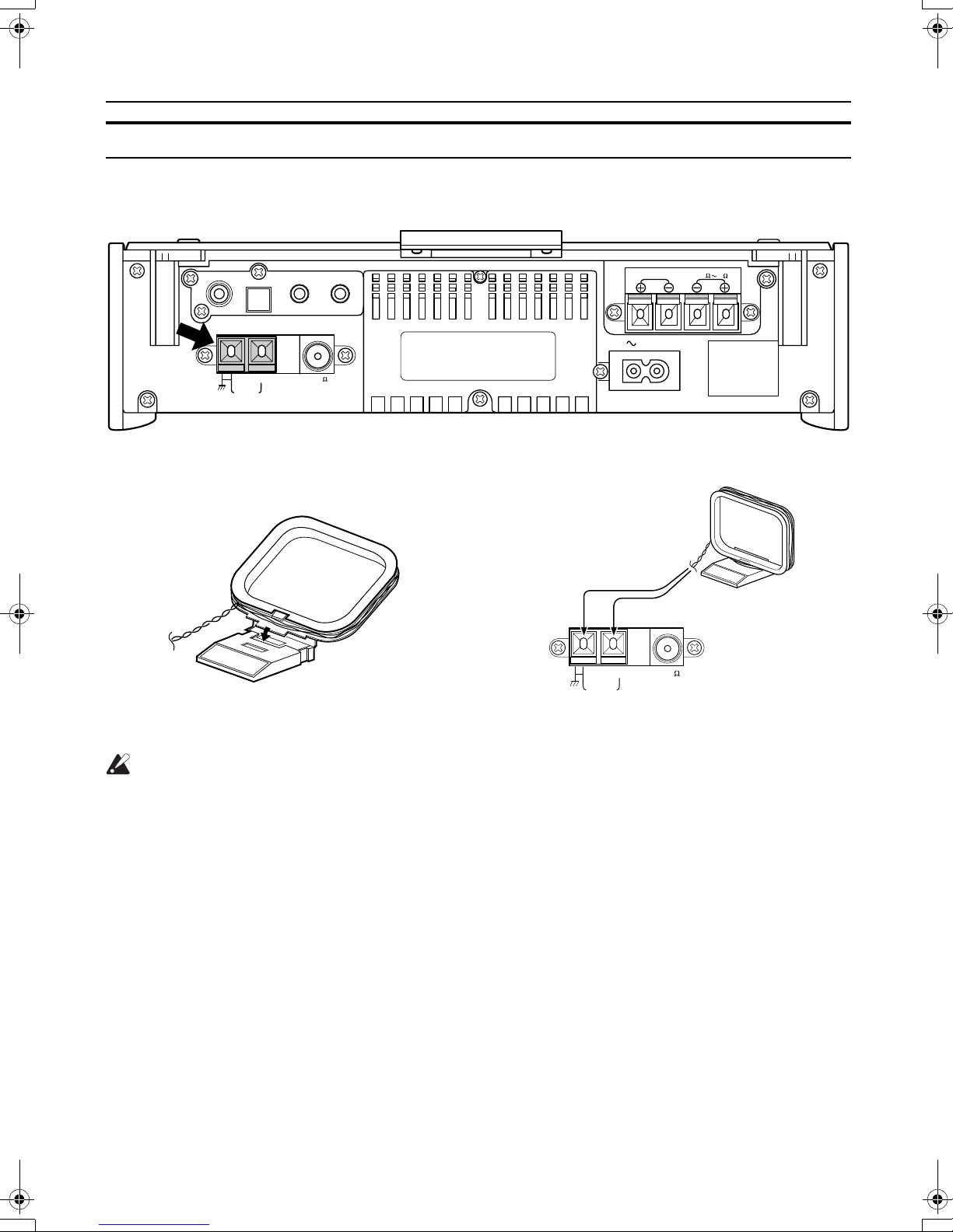
Connecting the AM Antenna
ANTENNA
AM EXT FM(75
)
COAXIAL
AM LOOP
Rear Panel of the Unit
Getting Started
Getting Started
Getting StartedGetting Started
SUB WOOFER
CD DIGITAL OUT
AM LOOP
OUT IN
MD
/
ANTENNA
AM EXT FM(75
COAXIAL
AUX
)
AM loop antenna (Supplied)
Attach the AM loop to its base by snapping the
tabs on the loop into the slot in the base.
SPEAKERS IMPEDANCE 4 16
R
AC IN
L
Turn the loop until you have the best reception.
CAUTION:
• To avoid noise, keep antennas away from the System, the connecting cord and the AC power
cord.
5
Page 8
Getting Started
Getting Started
Getting StartedGetting Started
CAUTION:
• Make all connections before plugging the System into an AC power outlet.
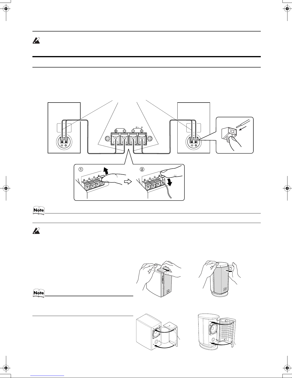
Connecting the Speakers
1. Open each of the terminals to connect the speaker wire leads.
2. Connect the speaker cords between the Speaker terminals of the Unit and the terminals of the Speakers.
Connect the cords with a black line to the (–) terminals and cords without a black line to the (+) terminals.
3. Close each of the terminals to securely connect the cords.
Right side (rear view) Left side (rear view)
• Since both speakers are the same, you can put either one to the right or left side.
Marked with a black line
SPEAKERS IMPEDANCE 4 16
RL
CAUTION:
• A TV may display irregular colors if located near the speakers. If this happens, set the speakers away from the TV.
Removing the speaker grilles
The speaker grilles can be moved.
When removing:
1. Pull the top forwards you with your fingers.
2. Also pull the bottom towords you.
• When removing the speaker grille from the FSSD990’s speaker, be careful not to damage the cabinet.
When attaching the speaker grille:
6
(FS-SD550) (FS-SD770 and FS-SD990)
(FS-SD550) (FS-SD770 and FS-SD990)
Speaker
grille
Speaker
grille
Page 9
Getting Started
Getting Started
Getting StartedGetting Started
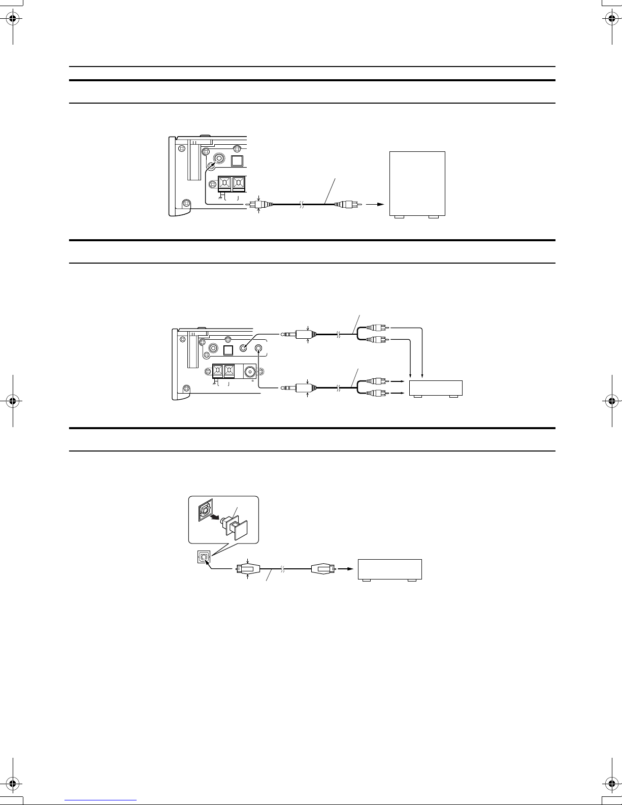
Connecting a Subwoofer
Connect a signal cord (not supplied) between the System’s SUBWOOFER terminal and the input terminal of an external subwoofer.
SUB WOOFER
CD DIGITAL OUT
ANTENNA
AM EXT FM(75 11mm Max/
AM LOOP
*
OUT IN
/
AUX
MD
Signal cord (not supplied)
11mm Max.
)
COAXIAL
Powered Subwoofer (not supplied)
* Use the plug whose diameter is 11mm or less.
Connecting External Equipment
Connect signal cords (not supplied) between the Syste m’s MD/AUX -O UT/IN te rminals and th e output /in put termin als of t he
external MD recorder, tape deck, etc.
You can then listen to the external source through the System or record the System’s CD player or tuner to the external unit.
Signal cord (not supplied)
11mm Max.
*
SUB WOOFER
* Use the plug whose diameter is 11mm or less.
CD DIGITAL OUT
ANTENNA
AM EXT FM(75
AM LOOP
OUT IN
/
AUX
MD
COAXIAL
Stereo mini-plug
)
Stereo mini-plug
Pin-plug x 2
Signal cord (not supplied)
11mm Max.
*
Pin-plug x 2
MD recorder or tape
deck (not supplied)
Connecting an MD Recorder, etc (Digital Output)
Unplug the cap and connect an optical digital cord (not supplied) between the System’s CD DIGITAL OUT terminal and the
input terminal of the MD recorder, etc.
You can record the digital output signal from the System’s CD Player to the MD recorder, etc.
Cap
CD DIGITAL OUT
11mm Max.
MD recorder, etc. (not supplied)
*
Optical digital cord (not supplied)
* Use the plug whose diameter is 11mm or less.
7
Page 10

Getting Started
Getting Started
Getting StartedGetting Started
Connecting the AC Power Cord
Firmly insert the supplied AC power cord into the AC inlet on the back of the Unit.
AC IN
Power cord
The provided AC power cord for this unit has certain one-way direction connections to prevent electric shock. Refer to the
illustration for correct connection.
CAUTIONS:
• ONLY USE THE JVC POWER CORD PROVIDED WITH THIS SYSTEM TO AVOID MALFUNCTION OR DAMAGE TO THE SYSTEM.
• BE SURE TO UNPLUG THE POWER CORD FROM THE OUTLET WHEN GOING OUT OR WHEN
THE SYSTEM IS NOT IN USE FOR AN EXTENDED PERIOD OF TIME.
Now you can plug the AC power cord into the wall outlet, and your System is at your command!
COMPU Play
JVC’s COMPU PLAY feature lets you control the most frequently used System functions with a single touch.
With One Touch Operation you can play a CD, turn on the radio, or listen to an external equipment with a single p ress o f the
play button for that function. One To uch Ope ration tur ns the po wer on fo r you , then st arts the functio n you have sp ecified. A t
the same time, the Top Cover moves backward to allow the Un it’s top button operation. If the System is not ready (no CD in
place), the System still powers on so you can insert a CD.
How One Touch Operation works in each case is explained in the section dealing with that function.
The COMPU PLAY buttons are:
On the Remote Control
CD #/8 button
FM/AM button
MD/AUX button
Automatic Power On
The System automatically turns on with the following operation.
• When you press the CD 0 button on the Remote Control or the OPEN/CLOSE button on the Unit, the System automatically
turns on and the T op Co v er opens to allo w CD setting. Ho wever , this operation does not change the function to CD.
When you press the POWER button to turn of f the System, the Top Co ver will be automatically closed if it is opened.
• When you press the DOOR SLIDE button on the Remote Control, the System automatically turns on and the Top Cover
moves backwards to allo w b utton operation.
When you press the POWER b utton to turn of f the System, the Top Cover will automatically moves back to the original position, if it is in the backward position.
8
Page 11

Basic Operations
REMOTE CONTROL
POWER
DIMMER
DISPLAY
AHB PRO
BASS
FADE
MUTING
VOLUME+,–
Turning the Power On and Off
Turning the System On
Press the POWER button.
The Top Cover moves backward and the Unit’s top buttons
appear. The display comes on and “HELLO” is displayed
once. The STANDBY/ON indicator lights in green.
The System comes on ready to continue in the mode it was
in when the power was last turned off.
■For example, if the last thing you were doing was listening to a CD, you are now ready to listen to a CD again. If
you wish, you can change to another source.
■If you were listening to the Tuner last, the Tuner comes
on playing the station it was last set to.
DIMMER SLEEP
AUTO
DISPLAY FM MODE
PRESET
PROGRAM
DOOR
AHB PRO
SLIDE
BASS TREBLE CANCEL
UP
SET
DOWN
FADE MUTING
CD
MD/AUX FM / AM
VOLUME
POWER
REPEATRANDOM
CD
DOOR SLIDE
TREBLE
PRESET
TUNINGFM/AMMD/AUX
AHB PRO CLOCK TIMER VOLUME
AHB PRO
STANDBY/ONPOWER OPEN/CLOSE
CD
MULTI CONTROL
CLOCK
UPDOWN
VOLUME+,–
Top Cover
PHONES
STANDBY/ON indicator
POWER
PHONES
When the System is Turned Off
(STANDBY MODE)
Each time you press the DIMMER button on the Remote
Control, the brightness of the backlighting changes as follows:
No backlighting = Dark backlighting
= (back to the beginning)
• When the System is turned off again after power on, the
brightness in Standby mode will be restored to the previous one since the brightness setting in Standby mode is
stored in memory.
Turning the System Off
Press the POWER button again.
The Top Cover moves back to the original position.
“GOOD BYE” is displayed and the display goes out , except
for the clock display. The STANDBY/ON ind icator lights in
red.
■Some power is always consumed even though power is
turned off (called Standby Mode).
■To switch off the System completely, unplug the AC
power cord from the wall outlet. When you unplug the
AC power cord, the clock will be reset to A M 12:00 after
about 20 minutes.
Adjusting the Brightness
(DIMMER)
You can adjust the brightness of the backlightin g for the display.
When the System is Turned On
Each time you press the DIMMER button on the Remote
Control, the brightness of the backlighting changes as follows:
Bright = Dark = (back to the beginning)
Adjusting the Volume
Press the VOLUME + button to increase the volume or
press the VOLUME – button to decrease it.
You can adjust the volume level between 0 and 50.
CAUTION:
• DO NOT turn on the System and/or start
playing any source without first setting the
VOLUME control to minimum, as a sudden
blast of sound could damage your hearing,
speakers and/or headphones.
For private listening
Connect a pair of headphones to the PHONES jack. No
sound comes out of the speakers.
Be sure to turn down the volume before connecting or putting on headphones.
9
Page 12

Basic Operations
Basic Operations
Basic OperationsBasic Operations
Fade-out Muting (FADE MUTING)
You can mute the output with one touch operation.
To mute the output, press the FADE MUTING button
on the Remote Control. Then, the output will be faded out
and becomes 0.
To release muting, press the FADE MUTING button once
again. Then, the output will be faded in to the original level.
Reinforcing the Bass Sound
(AHB PRO)
You can reinforce the bass sound to maintain rich, full bass
at low volume.
To get the effect, press the AHB (Active Hyper Bass)
PRO button.
The “AHB PRO” indicator lights up on the display.
To cancel the effect, press the button again.
The “AHB PRO” indicator goes out.
Tone Control (BASS/TREBLE)
You can control the tone by changing the bass and treble.
Showing the Time
(CLOCK/DISPLAY)
You can show the current time on the display.
To display the clock, press the CLOCK button on the
Unit or DISPLAY button on the Remote Control.
To return to the previous mode, press the same button
again.
• To let the clock work, you need to set the clock beforehand. (See “Setting the Clock” on page 17.)
Sliding the Top Cover
(DOOR SLIDE)
Each time you press the DOOR SLIDE button on the Remote Control, the Top Cover slides back and forth.
BASS Control
You can adjust the bass level (low frequency range level)
between –6 and +6. (0: Flat)
Press the BASS button on the Remote
1
Control.
Press the UP or DOWN button on the
2
Remote Control to adjust the bass level.
DOWN
BASS
UP
TREBLE Control
You can adjust the treble level (high frequency range level)
between –6 and +6. (0: Flat)
Press the TREBLE button on the
1
Remote Control.
Press the UP or DOWN button on the
2
Remote Control to adjust the treble
level.
DOWN
TREBLE
UP
Slide the Top Cover backward to allow Unit’s top button
operation. Slide it toward you to cover the buttons.
10
Page 13

Using the Tuner
REMOTE CONTROL
POWER
DIMMER SLEEP
AUTO
DISPLAY FM MODE
AUTO
PRESET
SET
4
PRESET
PROGRAM
<
FADE MUTING
MD/AUX FM / AM
DOOR
AHB PRO
SLIDE
BASS TREBLE CANCEL
UP
SET
DOWN
CD
VOLUME
REPEATRANDOM
CD
* When the System is in use, the display shows other items as well.
For simplicity, we show here only the items described in this section.
FM MODE
UP
>
DOWN
FM/AM
¢
FM/AM
PRESET
TUNING
FM mode
indicators
PRESET
TUNINGFM/AMMD/AUX
AHB PRO CLOCK TIMER VOLUME
4
MULTI CONTROL
CD
UPDOWN
¢
Band display, Frequency display, Preset channel
STEREO
MONO
You can listen to FM and AM stations. Stations can be
tuned in manually, automatically, or from preset memory
storage.
■Before listening to the radio:
• Make sure that both the FM and AM antennas are correctly connected. (See pages 4 and 5).
One Touch Radio
Just press the FM/AM button to turn on the System an d start
playing the station you were last tuned to.
■You can switch from any o ther sound sou rce to th e radio
by pressing the FM/AM button.
Tuning In a Station
Press the FM/AM button.
1
The Band and Frequency you were last tuned to appear
on the display.
(If the last station was selected using the preset number ,
the preset number appears first.)
Each time you press the button, the band alternates between FM and AM.
FM / AM
FMAM
(on the Remote Control)
Select a station using one of the follow-
2
ing methods.
●Manual Tuning
Press the 4 or ¢ button on the Unit or the Remote Control repeatedly to move from frequency to
frequency until you find the station you want.
OR
FM/AM
FMAM
(on the Unit)
●Auto Tuning
If you press and hold the 4 or ¢ button on the
Unit or the Remote Control for one second or more,
the frequency changes down, or u p, automatically until a station is found.
OR
●Preset Tuning using the Remote Control
(Possible only after presetting stations)
Select the desired preset number using the UP,
DOWN, > and < button on the Remote Control. After
1 second the display will show the preset number’s
band and frequency.
Example:
Press the UP button until the preset number 12 “P12”
appears.
UP
DOWN
or
(After 1 second)
●Preset Tuning using the Unit
Press the PRESET TUNING button to select the desired preset number.
Its band and frequency are displayed.
• In AM broadcast, reception sensitivity will be changed by
turning the AM loop antenna. Turn the AM loop antenna
for best reception.
11
Page 14

Using the Tuner
FM / AM
AUTO
PRESET
MONO
FM MODE
Using the Tuner
Using the TunerUsing the Tuner
Presetting Stations
You can preset up to 30 FM stations and up to 15 AM stations using the Remote Control.
• Preset numbers may have been set to factory test frequencies prior to shipment. This is not a malfunction. You
can preset the stations you want into memory by following
one of the presetting methods below.
Manual Presetting
SET STORED
FM / AM
When changing the
Band
Select a band by pressing the FM/AM
1
SET
UP
DOWN
or
FM = 30, AM = 15
button.
Press the 4 or ¢ button to tune in a
2
station.
Press the SET button.
3
“SET” will blink for 5 seconds.
Within 5 seconds, proceed to the next step.
When the display returns to the one set in step 2 after 5
seconds, press the SET button again.
SET
Auto Presetting
In each band, you can automatically preset FM-30, AM-15
stations. Preset numbers will be allocated as stations are
found, starting from the lowest frequency and moving up
the frequency.
(for 2 seconds)
Select a band by pressing the FM/AM
1
button.
Press the AUTO PRESET button on the
2
Remote Control for more than two seconds.
Repeat steps 1-2 for the other band.
3
■If you want to change the preset stations, carry out the
Manual Presetting for the desired preset numbers.
CAUTION:
• Even if the system is unplugged or if the
power failure occurs, the preset stations
will be stored for about 24 hours. However,
in case the preset stations are erased, you
will need to preset the stations again.
Press the UP, DOWN, >, or < button
4
within 5 seconds to select the preset
number.
UP or DOWN button:Increase or decrease the preset
number by 1.
Pressing and holding the button
will continuously increase or decrease the preset number.
> or < button: Increase or decrease the preset
number by 1.
Pressing and holding the button
will rapidly increase or decrease
the preset number.
Press the SET button within 5 seconds.
5
“STORED” appears and after 2 seconds, the display returns to the broadcast frequency display.
Repeat above steps 1 to 5 for each sta-
6
tion you want to store in memory with a
preset number.
To change the preset stations, repeat the same
steps as above.
To Change the FM
Reception Mode
When you are tuned into an FM stereo broadcast, the
“STEREO” indicator lights up and you can hear stereo effects.
If an FM stereo broadcast is hard to receive or noisy, you
can select Monaural mode. Reception improves, but you
lose stereo effect.
Press the FM MODE button on the Remote Control
so that the “MONO” indicator lights up on the display.
To restore the stereo effect, press the FM MODE button
on the Remote Control so that the “MONO” indicator goes off.
12
Page 15

Using the CD Player
REMOTE CONTROL
POWER
DIMMER SLEEP
AUTO
DISPLAY FM MODE
PRESET
PROGRAM
PROGRAM
RANDOM
SET
CD
#/8
4
REPEATRANDOM
DOOR
SLIDE
BASS TREBLE CANCEL
UP
SET
DOWN
CD
VOLUME
CD
AHB PRO
<
FADE MUTING
MD/AUX FM / AM
REPEAT
CD
0
CANCEL
UP
>
DOWN
¢
7
PRESET
TUNINGFM/AMMD/AUX
AHB PRO CLOCK TIMER VOLUME
4
Track number, Playing time, Preset number
RANDOM ALL
PROGRAM
CD
Top Cover
UPDOWN
MULTI CONTROL
¢
7
CD
#¥8
STANDBY/ONPOWER OPEN/CLOSE
987654321
2019181716151413121110
PHONES
OPEN/CLOSE
Play mode indicators
* When the System is in use, the display shows other items as well.
For simplicity, we show here only the items described in this section.
You can use Normal, Random, Program or Repeat Play. Repeat Play can repeat all the tracks or just one of the tracks
on the CD.
Here are the basic things you need to know to play a CD and
locate the different tracks on it.
This unit has been designed only to playback the CDs bearing the marks.
When playing a CD-R or CD-RW
You can play back finalized CD-R or CD-RW recorded music CD format.
■You can play back CD-R or CD-RW like CD.
■Some CD-R or CD-RW may not be played back on this
unit because of their disc characteristics, damage or stain
on them, or if the player lens is dirty.
■The reflection factor of CD-RW is lower than that of oth-
er CD, possibly causing CD-RW to take longer to read.
The Quickest Way To Start a CD Is With the One
Touch Operation
■Press the CD #¥8 button on the Remote Control.
• The power is automatically turned on and the Top Cover
moves backward to allow the Unit’s top button operation. If a CD is already inserted, it will start playing from
the first track.
• If no CD is inserted, “NO DISC” appears on the display
and the CD Player remains in Stop mode.
Music calendar
Track number exceeding 20 is
not displayed.
To Insert a CD
Press the OPEN/CLOSE button on the
1
Unit (or the CD 0 button on the
Remote Control).
The Top Cover opens.
Place a CD, with its label side up as
2
shown below. Press down on the CD’s
center until you hear a click.
Press the OPEN/CLOSE button (or CD 0
3
button) again to close the Top Cover.
• T o close t he Top Co ver and pl ay the CD, you can just
press the CD #¥8 button.
■You can place an 8 cm (3'') CD without an adaptor.
■If the CD cannot be read correctly (because it is
scratched, for example), “ 0 0:00” appears on the disp lay.
■You can insert a CD while listening to the other source.
CAUTION:
• DO NOT try to open or close the Top Cover
by hands as it will be damaged.
13
Page 16

Using the CD Player
Using the CD Player
Using the CD PlayerUsing the CD Player
To Unload a CD
Take out the CD as shown below.
To stop playing and remove the CD, press the OPEN/
CLOSE button on the Unit or CD 0 button on the Remote
Control to open the Top Cover.
To pause, press the CD #¥8 button. The playback time
blinks on the display.
To cancel pause, press the same button again. Play continues from the point where it was paused.
To Select a Track or Passage within a Track
During playback, press the 4 or ¢ (< or >) button to select the track you want.
• The selected track starts playing.
•Press the ¢ or > button once to skip to the beginning of the next track.
•Press the 4 or < button to skip to the beginning of
the track being played. Press twice quic kly to skip to
the beginning of the previous track.
• When the > or < button on the Remote Control is
kept pressing, the track continuously skips.
Search Play
Holding down the 4 or ¢ button, during pl ayback, will
fast forward/backwards the CD so you can quickly find a
particular passage in the track you are listening to.
Basics of Using the
CD Player-Normal Play
To Play a CD
Insert a CD.
1
Press the CD
2
The first track of the CD begins playing.
Track number Playback time
• The track number that has already played disappears
from the music calendar.
• The CD Player automatically stops when the last
track of the CD has finished playing.
To stop playing the CD, press the 7 button.
The following information for the CD is displayed.
Total track number Total playback time
#¥8
button.
Programming the
Playing Order of the Tracks
You can program the playing order of the tra cks using the
Remote Control.
■You can program up to 32 tracks in any desired order in-
cluding the same tracks.
■You can only make a program when the CD Player is
stopped.
Insert a CD.
1
Press the CD #/8 button.
2
Press the 7 button to stop the CD.
3
Press the PROGRAM button.
4
The System enters the programming mode and the
“PROGRAM” indicator lights up.
PROGRAM
PROGRAM
Press the UP, DOWN, >, or < button to
5
select the track to program.
UP or > button: Increases the track number by 1.
DOWN or < button:Decreases the track number by 1.
• When the > or < button is kept pressing, the track
number changes rapidly.
14
Page 17

Press the SET button.
6
UP
DOWN
Repeat steps 5 and 6 to select the other
7
SET
Total playback time of the programmed tracks
Program order number
(After 2 seconds)
tracks for the program.
You can see the total playback time of programmed
tracks on the display. Also, you can see the programmed
tracks on the music calendar.
Press the CD
8
The System plays the tracks in the order you have programmed them.
■You can skip to a particular program track by pressing the
4 or ¢ button during Program Play.
■To stop playing, press the 7 button once.
To confirm the programmed tracks while the CD
player is stopped,
ton; the tracks making up the program will successively be
displayed in the programmed order.
To delete all the tracks in the program,
press the 7 button. Pressing the CD 0 button to open the
Top Cover will also clear the programmed tracks.
To exit the program mode once,
is stopped, press the PROGRAM button to light off the
“PROGRAM” indicator.
• If the total playback time of the programmed tracks exceeds 99 minutes 59 seconds, the total playback time will
go out on the display.
• If you try to program the 33rd track, “MEMORY FULL” appears on the display for about 2 seconds.
#/8
button.
each time press the 4 or ¢ but-
in stop mode,
while the CD Player
Using the CD Player
Using the CD Player
Using the CD PlayerUsing the CD Player
Random Play
The tracks will play in no special order when you use this
mode.
Press the RANDOM button on the
1
Remote Control.
The “RANDOM” indicator lights up on the display.
Press the CD #/8 button.
2
The tracks are played in random order.
To skip a track during playback,
to jump to the next track in the random sequence. Press the
4 button to jump back to the start of a track being played.
To exit Random Play mode,
stopped, press the RANDOM button to light off t he “ RANDOM” indicator and carry out Normal Play, or press the CD
0 button to open the Top Cover.
press the ¢ button
while the CD Player is
Repeating Tracks
You can repeat all tracks or individual track , as many ti mes
as you like.
Press the REPEAT button on the Remote Control.
The Repeat indicator changes with each press of the button,
as shown below.
=
ALL=blank display = (back to the
beginning)
: Repeats one track.
: In Normal Play mode, repeats all the tracks.
ALL
In Program Play mode, repeats all the tracks
in the program.
In Random Play mode, repeats all the tracks
in random order.
To exit Repeat mode,
Repeat indicator on the display goes out.
■In Random Play, cannot be selected.
■Repeat mode remains in effect even when you change th e
play mode.
press the REPEAT button until the
To Modify the Program
Modify the contents of the program while the CD Player is
stopped.
Each time you press the CANCEL button, the last track in
the program is deleted. To add new tracks to the end of the
program, repeat above steps 5 to 7.
15
Page 18

Using External Equipments
REMOTE CONTROL
POWER
DIMMER SLEEP
AUTO
DISPLAY FM MODE
PRESET
PROGRAM
REPEATRANDOM
DOOR
CD
AHB PRO
SLIDE
BASS TREBLE CANCEL
MD/AUX
UP
SET
DOWN
FADE MUTING
CD
MD/AUX FM / AM
VOLUME
MD/AUX
PRESET
TUNINGFM/AMMD/AUX
AHB PRO CLOCK TIMER VOLUME
CD
MULTI CONTROL
UPDOWN
Listening to External
Equipment
You can listen to external equipment such as MD recorder,
turntable or other auxiliary.
■First make sure that the external equipment is properly
connected to the System. (See page 7).
Set the VOLUME control to the mini-
1
mum position.
Press the MD/AUX button.
2
“MD/AUX” appears on the display.
Start playing the external equipment.
3
Adjust the VOLUME control to the
4
desired listening level.
Apply sound effects, if you wish.
5
■Press the AHB PRO button to reinforce the bass sound.
■Press the BASS/TREBLE button on the Remote Control
to control the tone. (See “Tone Control” on page 10.)
To exit MD/AUX mode, you will automatically switch
out of MD/AUX mode when you select another source.
Recording the System’s Source
to External Equipment
You can record the System’s source to external equipment
which is connected to the MD/AUX-IN/OUT or CD DIGITAL OUT terminals of the System, such as cassette deck or
MD recorder, etc.
■First make sure that the external equipment is properly
connected to the System. (See page 7).
Play the System’s CD Pla y er or tune in
1
to a station.
■The recording level is not affecte d by the VOLUME level
set by the System. Also it is not affected by the so und effects.
• For operation of the external equipment, refer to its Instructions.
• For operation of the external equipment, refer to its Instructions.
16
Page 19

Using the Timers
REMOTE CONTROL
POWER
DIMMER SLEEP
AUTO
DISPLAY FM MODE
SLEEP
PRESET
PROGRAM
DOOR
AHB PRO
SLIDE
BASS TREBLE CANCEL
UP
SET
DOWN
FADE MUTING
CD
MD/AUX FM / AM
REPEATRANDOM
CD
PRESET
TUNINGFM/AMMD/AUX
AHB PRO CLOCK TIMER VOLUME
4
MULTI CONTROL
CD
UPDOWN
¢
CLOCK
TIMER
ON time, OFF time,
Source, Volume
VOLUME
* When the System is in use, the display shows other items as well.
For simplicity, we show here only the items described in this section.
The timers let you control listening functions automatically.
Setting the Clock
• Use the Unit’s button to set the clock.
• When you plug the AC power cord into the wall outlet,
the time indication “AM 12:00” blinks on the display.
• The clock must be correctly set for the timers to work.
• The procedure must be completed within two minutes.
Otherwise, the setting is cleared and must be repeated
from the beginning.
Press the POWER button.
1
Then, the Unit’s top buttons appear.
SLEEP
Press the ¢ or 4 button to set the
5
SLEEP indicator
minute.
Timer indicator
Press the CLOCK button.
6
The selected time is set and the seconds start counting
from 0.
CAUTION:
• If there is a power failure, the clock loses its
setting after about 20 minutes. “AM 12:00”
blinks on the display and the clock must be
reset.
• The clock may gain or lose one to two minutes per month.
CLOCK
CD
MULTI CONTROL
(for 2 seconds)
Press the CLOCK button on the Unit for
2
more than two seconds.
The hour digit of the time indication rapidly blinks on
the display.
Press the ¢ or 4 button on the Unit
3
to set the hour.
Pressing the ¢ button moves the time forwards and
pressing the 4 button moves it backwards. Hold
down the button to move the time rapidly.
Press the CLOCK button.
4
The minute digits of th e time indicatio n rapidly bli nk on
the display.
CLOCK
UPDOWN
Setting the Daily Timer
Once you have set the Daily Timer, the timer will be activated at the same time every day.
The Timer indicator on the display shows that the Daily
Timer you have set is in effect.
• Use the Unit’s button to set the timer.
• Perform each setting within 30 seconds. Otherwise, setting will be cleared and the procedure must be repeated
from the beginning.
17
Page 20

Using the Timers
Using the Timers
Using the TimersUsing the Timers
Setting the ON time (Example: AM 10:15).
1
1. Press the TIMER button on the Unit for more than
two seconds.
The Timer indicator lights up and the hour d igit of the
current ON time blinks on the display.
• When the clock is not set, “CLOCK” and “ ADJUST”
appear alternately on the display. Set the clock first.
Press the ¢ or 4 button on the Unit to set the
hour you want the Unit to come on.
Pressing the ¢ button moves the time forwards and
pressing the 4 button moves it backwards. Hold
down the button to move the time rapidly.
2. Press the TIMER button.
The minute digits of the ON time blink on the displa y.
Set the minute you want the Unit to be turned off, using the ¢ and 4 buttons.
Selecting the music source.
3
1. Press the TIMER button.
The “TUNER” or “CD” blinks on the display.
2. Press the ¢ or 4 button to select the music
source you want to listen to.
The display changes as shown below.
TUNER
Setting the volume level.
4
1. Press the TIMER button.
The current volume setting blinks on the display.
2. Press the ¢ or 4 button to select the volume level.
-- :The current volume level will be used.
0 to 50 :When the timer is turned on, the Volume will
ÔCDÔ
(back to the beginning)
be automatically set to the selected level.
Set the minute you want the Unit to come on, using
the ¢ or 4 button.
Setting the OFF time (Example : PM 1 : 30) .
2
1. Press the TIMER button.
The hour digit of the OFF time blinks on the display.
(The same time as the ON time will be automatically
set.)
Set the hour you want the Unit to be turned off, using
the ¢ or 4 button.
2. Press the TIMER button.
The minute digits of the OFF time blink on the display.
Press the TIMER button.
5
The timer setting is completed and the display returns to
the display before you set the Timer. The Timer indicator remains lit.
Before turning off the System, prepare
6
the music source selected in step 3.
TUNER: Tune in to the desired station.
CD: Insert a CD. (Playback will start from the first
track at Timer on.)
Press the POWER button to turn off the
7
System.
In standby mode, you can see the Timer indicator ( )
on the display.
• When the timer turns on, the Timer indicator starts blinking and the prepared source in step 6 will be played.
To cancel the timer, press the TIMER button. The
Timer indicator ( ) goes out on the display.
To re-activate the cancelled timer, press the TIMER button to light the Timer indicator ( ).
At this time, you can see the current timer settings. Each
setting appears on the display for two seconds in the order of ON time, OFF time, music source and volume.
To change the timer setting, repeat the setting procedure from the beginning.
CAUTION:
• If the System is unplugged, or a power failure occurs, the timer setting will be lost.
You will need to reset the clock first, then
the timer.
18
Page 21

Setting the SLEEP Timer
(Using the Remote Control)
Use the Sleep Timer to turn the System off after a certain
number of minutes when it is playing. By setting the Sleep
Timer, you can fall asleep to music and know that your System will turn off by itself rather than play all night.
■You can only set the Sleep Timer when the System is on
and a source is playing.
Play a CD or tune in to the desired sta-
1
tion.
Press the SLEEP button on the Remote
2
Control.
The “SLEEP” indicator lights up.
■When the clock is not set, “CLOCK” and “ADJUST”
appear alternately on th e disp la y. Set th e c lock at first.
Set the length of time you want the
3
source to play before shutting off.
• Each time you press the SLEEP button, it changes
the number of minutes shown on the display in this
sequence:
10
= 20 = 30 = 60 = 90 = 120 = Cancelled =
(back to the beginning)
Using the Timers
Using the Timers
Using the TimersUsing the Timers
The selected number of minutes for the Sleep Timer will
stop blinking five seconds later and the display returns to
the original one before setting the Sleep Timer. (The display
is dimmed.)
The System is now set to turn off after the number of minutes you set.
To Confirm the Sleep Time:
When the SLEEP button is pressed, the remaining sleep
time is displayed. Wait until the display returns to the original display.
To Cancel the SLEEP Timer Setting:
Press the SLEEP button until the “SLEEP” indicator goes
out on the display.
Turning off the System also cancels the SLEEP Timer.
■If you are setting the Daily Timer, the System wi ll be
turned on at the set time to wake you up.
19
Page 22

Care And Maintenance
Handle your CDs carefully, and they will last a long time.
Compact Discs
• Only CDs bearing this mark can
be used with this System. However, continued use of irregular
shape CDs (heart-shape, octagonal, etc.) can damage the System.
• Remove the CD from its case by
holding it at the edges while
pressing the case’s center hole
lightly.
• Do not touch the shiny surface of
the CD, or bend the CD.
• Put the CD back in its case after
use to prevent warping.
• Be careful not to scratch the surface of the CD when placing it
back in the case.
• A v oid exposure t o direct sunlight,
temperature extremes, and moisture.
• A dirty CD may not play correctly . If a CD does become dirty,
wipe it with a soft cloth in a
straight line from center to edge.
Cleaning the Lens
If the lens in the CD pickup is dirty, dropout, etc., could degrade sound.
Open the Top Cover and clean the lens as shown.
• Use a blower (available from a camera store) to blow
dust off the lens.
Blower
Lens
• If there are fingerprints, etc. on the lens, gently wipe
clean with a cotton swab.
CAUTION:
• Do not use any solvent (for example, conventional record cleaner, spray thinner,
benzine, etc.) to clean a CD.
General Notes
In general, you will have the best performance by keeping
your CDs and the mechanism clean.
• Store CDs in their cases, and keep them in cabinets or on
shelves.
• Keep the System’s Top Cover closed when not in use.
Cleaning the unit
• Stains on the unit
Should be wiped off with a soft cloth. If the unit is heav ily
stained, wipe it witha cloth soaked in water-diluted neutral detergent and wrung well, then wipe clean with a dry
cloth.
• Since the unit may deteriorate in quality, become damaged or get its paint peeled off, be careful about the followings.
- DO NOT wipe it with a hard cloth.
- DO NOT wipe it strong.
- DO NOT wipe it with thinner or benzine.
- DO NOT apply any volatile substance such as insecti-
cides to it.
- DO NOT allo w any rubber or plastic to remain in con-
tact with it for a long time.
Moisture Condensation
Moisture may condense on the lens
inside the System in the following
cases:
• After turning on heating in the
room.
• In a damp room.
• If the System is brought directly
from a cold to a warm place.
Should this occur, the System may
malfunction. In this case, leave the
System turned on for a few hours until the moisture evaporates, unplug
the AC power cord, and then plug it
in again.
20
Page 23

Troubleshooting
• If you are having a problem with your S ystem, check this
list for a possible solution before calling for service.
Symptom Possible Cause Action
No sound is heard. • Connections are incorrect, or loose.
• Headphones are connected.
Poor radio reception • The antenna is disconnected.
• The AM Loop Antenna is too close
to the System.
• The FM Wire Antenna is not properly extended and positioned.
The CD skips. The CD is dirty or scratched. Clean or replace the CD.
The CD does not play. The CD is upside down. Put the CD in with the label side up.
Unable to operate the Remote Control. • The path between the Remote Con-
trol and the sensor on the Unit is
blocked.
• The batteries have lost their charge.
Operations are disabled. The built-in microprocessor has mal-
functioned due to external electrical interference.
• If you cannot solve the problem from the hints given
here, or the System has been physically damaged, call a
qualified person, such as your dealer , for service.
• Check all connections and make corrections. (See pages 4 to 8.)
• Disconnect the headphones.
• Reconnect the antenna securely.
• Change the position and direction of
the AM Loop Antenna.
• Extend FM W ire Ant enna to the be st
reception position.
• Remove the obstruction.
• Replace the batteries.
Unplug the System then plug it back in.
NO DISC appears.
There is no disc in the tray, or CD, CD-R
or CD-RW that hasn’t yet been finalized
(including blank discs) has been inserted.
Insert a CD, CD-R or CD-RW that has
been finalized.
21
Page 24

Specifications
Amplifier
Output Power
Input Sensitivity/Impedance (1 kHz)
MD/AUX IN
Output Sensitivity/Impedance (1 kHz)
MD/AUX OUT
CD DIGITAL OUT (Optical out)
Speaker terminals
Subwoofer out
Phones
CD Player
Signal-To-Noise Ratio
Wow And Flutter
Tuner
FM Tuner
Tuning Range 87.5 - 108.0 MHz
AM Tuner
Tuning Range
Center Unit (FS-SD550/SD770/SD990)
Dimensions
Mass
19 watts per channel, min. RMS, at 4 ohms from 80 Hz to 20 kHz,
with no more than 10% total harmonic distortion
500 mV/47 kohms
500 mV/5 kohms
–21 dBm - –15 dBm
4 - 16 ohms
230mV/19kohms
16 ohms - 1 kohm
0 - 15 mW/ch output into 32 ohms
90 dB
Unmeasurable
530 - 1 710 kHz
300mm
(11 –
Approx. 3.0kg (6.7 lbs)
75mm ✕ 215mm (W/H/D)
✕
13
/16" ✕ 3" ✕ 8 – 1/2")
Speaker Specifications (each unit)
FS-SD550
Speakers
Impedance
Dimensions
Mass
FS-SD770
Speakers
Impedance
Dimensions
Mass
FS-SD990
Speakers
Impedance
Dimensions
Mass
Accessories
8 cm cone
4 ohms
109mm
(4 –
1.5kg (3.4 lbs)
8 cm cone
4 ohms
120mm
(4 –
1.4kg (3.1 lbs)
8 cm cone
4 ohms
120mm
(4 –
1.4kg (3.1 lbs)
Power Cord (1)
AM Loop Antenna (1)
Remote Control (1)
Batteries R6P (SUM-3)/AA (15F) (2)
FM Wire Antenna (1)
Speaker Cords (2)
217mm ✕ 165mm (W/H/D)
✕
5
/16" ✕ 8 – 9/16" ✕ 6 – 1/2")
246mm ✕ 162mm (W/H/D)
✕
3
/4" ✕ 9 – 11/16" ✕ 6 – 7/16")
246mm ✕ 162mm (W/H/D)
✕
3
/4" ✕ 9 – 11/16" ✕ 6 – 7/16")
Power Specifications
Design and specifications are subject to change without notice.
22
Power Requirements
Power Consumption
AC 120 V ~ , 60 Hz
28 watts (power on mode)
2.1 watts (in Standby mode)
Page 25

QUALITY SERVICE
HOW TO LOCATE YOUR JVC SERVICE CENTER
TOLL FREE : 1-800-537-5722
http://www.jvcservice.com
Dear customer:
In order to receive the most satisfaction from your purchase, read the instruction booklet before operating the unit. In the event that repair
is necessary, or for the address nearest your location, please refer to the factory service center list below or within the Continental United
States, Call 1-800-537-5722 for your authorized servicer. Remember to retain your Bill of Sale for Warranty Service.
–JVC
JVC SERVICE & ENGINEERING
COMPANY OF AMERICA
DIVISION OF JVC AMERICAS CORP.
FACTORY SERVICE CENTER LOCATIONS
10 New Maple Avenue
Pine Brook, NJ 07058-9641
(973) 396-1000
5665 Corporate Avenue
Cypress, CA 90630-0024
(714) 229-8011
13 Cummings Park
Woburn, MA 01801
(781) 376-9100
Sophisticated electronic products may require occasional service. Just as quality is a keyword in the engineering and production of
the wide array of JVC products, service is the key to maintaining the high level of performance for which JVC is world famous. The
JVC service and engineering organization stands behind our products.
If you ship the product
Pack your JVC unit in the original carton or one of equivalent
size and strength. Enclose, with the unit, a letter stating the
problem or symptom that exists and also a copy of the receipt
or bill of sale you received when you purchased your JVC unit.
Print your home return address on the outside and the inside
of the carton. Send to the appropriate JVC Factory Service
Center as listed above.
1500 Lakes Parkway
Lawrenceville, GA 30243-5857
(770) 339-2582
2969 Mapunapuna Place
Honolulu, HI 96819-2040
(808) 833-5828
8192 State Road 84
Davie, FL 33324
(954) 472-1960
NATIONAL HEADQUARTERS
JVC SERVICE & ENGINEERING COMPANY OF AMERICA
DIVISION OF JVC AMERICAS CORP.
1700 Valley Road
Wayne, NJ 07470
• • •
To prevent electrical shock, do not open the cabinet. No user
serviceable parts inside.
Refer servicing to qualified service personnel.
705 Enterprise Street
Aurora, IL 60504-8149
(630) 851-7855
10700 Hammerly, Suite 110
Houston, TX 77043
(713) 935-9331
890 Dubuque Avenue
South San Francisco, CA 94080-1804
(650) 871-2666
Don’t service it yourself.
CAUTION
ACCESSORIES
To purchase accessories for your JVC product, you may contact your local JVC Dealer.
Or from the 48 Continental United States call toll free : 800-882-2345
(1099)
BT-51001-4
Page 26

LIMITED W ARRANTY AUDIO-1
JVC COMPANY OF AMERICA warrants this product and all parts thereof, except as set forth below ONLY TO THE
ORIGINAL
PURCHASER AT RETAIL to be FREE FROM DEFECTIVE MATERIAL AND WORKMANSHIP from the date of original retail
purchase for the period as shown below. (“The Warranty Period.”)
PARTS LABOR
THIS LIMITED WARRANTY IS VALID ONLY IN THE FIFTY(50) UNITED STATES, THE DISTRICT OF COLUMBIA AND IN
COMMONWEALTH OF PUERTO RICO.
WHAT WE WILL DO:
If this product is found to be defective, JVC will repair or replace defective parts at no charge to the original owner. Such
repair and replacement services shall be rendered by JVC during normal business hours at JVC authorized service
centers. Parts used for replacement are warranted only for the remainder of the Warranty Period. All products and parts
thereof may be brought to a JVC authorized service center on a carry-in basis except for Television sets having a screen
size 25 inches and above which are covered on an in-home basis.
WHAT YOU MUST DO FOR WARRANTY SERVICE:
Return your product to a JVC authorized service center with a copy of your bill of sale. For your nearest JVC authorized
service center, please call toll free: (800)537-5722.
If service is not available locally, box the product carefully, preferably in the original carton, and ship, insured, with a copy of
your bill of sale plus and letter of explanation of the problem to the nearest JVC Factory Service Center, the name and
location of which will be given to you by the toll-free number.
If you have any questions concerning your JVC Product, please contact our Customer Relations Department.
WHAT IS NOT COVERED:
This limited warranty provided by JVC
1. Products which have been subject to abuse, accident, alteration, modification, tampering, negligence, misuse, faulty
installation, lack of reasonable care, or if repaired or serviced by anyone other than a service facility authorized by JVC
to render such service, or if affixed to any attachment not provided with the products, or if the model number or serial
number has been altered, tampered with, defaced or removed;
2. Initial installation and installation and removal for repair;
3. Operational adjustments covered in the Owner’s Manual, normal maintenance, video and audio head cleaning;
4. Damage that occurs in shipment, due to act of God, and cosmetic damage;
5. Signal reception problems and failures due to line power surge;
6. Video Pick-up Tubes/CCD Image Sensor, Cartridge, Stylus(Needle) are covered for 90 days from the date of purchase;
7. Accessories;
8. Batteries (except the Rechargeable Batteries are covered for 90 days from the date of purchase);
There are no express warranties except as listed above.
THE DURATION OF ANY IMPLIED WARRANTIES, INCLUDING THE IMPLIED WARRANTY OF MARCHANTABILITY, IS
LIMITED TO THE DURATION OF THE EXPRESS WARRANTY HEREIN.
JVC SHALL NOT BE LIABLE FOR THE LOSS OF USE OF THE PRODUCT, INCONVENIENCE, LOSS OR ANY OTHER
DAMAGES, WHETHER DIRECT, INCIDENTAL OR CONSEQUENTIAL (INCLUDING, WITHOUT LIMITATION, DAMAGE
TO TAPES, RECORDS OR DISCS) RESULTING FROM THE USE OF THIS PRODUCT, OR ARISING OUT OF ANY
BREACH OF THIS WARRANTY. ALL EXPRESS AND IMPLIED WARRANTIES, INCLUDING THE WARRANTIES OF
MERCHANTABILITY AND FITNESS FOR PARTICULAR PURPOSE, ARE LIMITED TO THE WARRANTY PERIOD SET
FORTH ABOVE.
Some states do not allow the exclusion of incidental or consequential damages or limitations on how long an implied
warranty last, so these limitations or exclusions may not apply to you. This warranty gives you specific legal rights and you
may also have other rights which vary from state to state.
JVC COMPANY OF AMERICA 1700 Valley Road
DIVISION OF JVC AMERICAS CORP. Wayne, NJ 07470
1YR 1YR
does not cover:
REFURBISHED PRODUCTS CARRY A SEPARATE WARRANTY, THIS WARRANTY
REFURBISHED PRO DUCT WARRANTY, PLEASE REFER TO THE REFURBISHED PRODUCT WARRANTY INFORMATION
PACKAGED WITH EACH REFURBISHED PRODUCT.
For customer use:
Enter below the Model No. and Serial No. which is located either on the rear, bottom or side of the cabinet. Retain this
information for future reference.
Model No.: Serial No.:
Purchase date:
DOES NOT APPLY. FOR DETAILS OF
Name of dealer:
Page 27

VICTOR COMPANY OF JAPAN, LIMITED
EN
0201MZMCREHIT
 Loading...