

Page 1
SUBWOOFER
LEVEL
VOLUME
CD
TUNER
BAND
MD
/TAPE
DOWN
SET
UP
TREBLE CANCELBASS
RANDOM REPEATPROGRAM
AUTO
PRESET
VOLUME
GAIN SELECT
CD
FM MODE AUXDISPLAY
SLEEP POWERDIMMER
REMOTE CONTROL RM-RXFS8000
PRESET
TUNING
BASS
CONTROL
AUX
POWER
MD/TAPE
TUNER
BAND
CD
OPEN/CLOSE
SLEEP
CLOCK
UPMULTI CONTROLDOWN
VOLUME
STANDBY
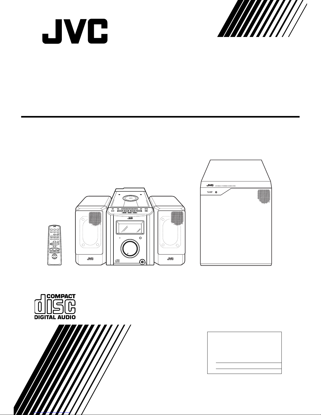
ULTRA COMPACT COMPONENT SYSTEM
FS-
8000
PHONES
SP-PW8000
SP-FS8000 CA-FS8000 SP-FS8000
For Customer Use:
Enter bel ow the Model No. and Serial No.
which are located eit her on the rear, bottom or side of the cabinet. Retain this
information for future reference.
Model No.
Serial No.
INSTRUCTIONS
MANUEL D’INSTRUCTIONS
LVT0329-001A
[J]
ULTRA COMPACT COMPONENT SYSTEM
SYSTEME DE COMPOSANTS ULTRA COMPACT
FS-8000
Consists of CA-FS8000, SP-FS8000 and SP-PW8000
Composé des CA-FS8000, SP-FS8000 et SP-PW8000
Page 2
G-1
Warnings, Cautions and Others /
Mises en garde, précautions et indications diverses
(For U.S.A)
The lightning flash with arrowhead symbol,
within an equilateral triangle is intended to
alert the user to the presence of uninsulated
“dangerous voltage” within the product’s
enclosure that may be of sufficient magnitude to constitute a risk of electric shock to
persons.
The exclamation point within an equilateral
triangle is intended to alert the user to the
presence of important operating and maintenance (servicing) instructions in the literature
accompanying the appliance.
CAUTION
RISK OF ELECTRIC
SHOCK
CAUTION: TO REDUCE THE RISK OF ELECTRIC SHOCK
DO NOT REMOVE COVER (OR BACK)
NO USER SERVICEABLE PARTS INSIDE
REFER SERVICING TO QUALIFIED SERVICE PERSONNEL.
WARNING: TO REDUCE THE RISK OF FIRE
OR ELECTRIC SHOCK, DO NOT EXPOSE
THIS APPLIANCE TO RAIN OR MOISTURE.
INFORMATION
This equipment has been tested and found to comply with the limits for a Class B digital device, pursuant to Part 15 of the FCC Rules. These limits are
designed to provide reasonable protection against
harmful interference in a residential installation. This
equipment generates, uses, and can radiate radio
frequency energy and, if not installed and used in
accordance with the instructions, may cause harmful
interference to radio communications. However,
there is no guarantee that interference will not occur
in a particular installation. If this equipment does
cause harmful interference to radio or television
reception, which can be determined by turning the
equipment off and on, the user is encouraged to try
to correct the interference by one or more of the following measures:
– Reorient or relocate the receiving antenna.
– Increase the separation between the equipment
and receiver.
– Connect the equipment into an outlet on a circuit
different from that to which the receiver is connected.
– Consult the dealer or an experienced radio/TV
technician for help.
Page 3
G-2
1. CLASS 1 LASER PRODUCT
2.
DANGER:
Invisible laser radiation when open and
interlock failed or defeated. Avoid direct exposure to
beam.
3.
CAUTION:
Do not open the top cover. There are no
user ser viceable pa r ts insid e the uni t; leave all servicing to qualitied service personnel.
1. PRODUIT LASER CLASSE 1
2.
ATTENTION:
Radiation laser invisible quand
l’appareil est ouvert ou que le verrouillage est en
panne ou désactivé. Eviter une exposition directe
au rayon.
3.
ATTENTION:
Ne pas ouvrir le couvercle du dessus.
Iln’y a aucune pièce utilisable à l’intérier. Laisser à
un personnel qualifié le soi n de répare r votre appareil.
CA UTION
To reduce the risk of electrical shocks, fire, etc.:
1. Do not remove screws, covers or cabinet.
2. Do not expose this appliance to rain or moisture.
ATTENTION
Afin d’èviter tout risque d’électrocution, d’lncendie. etc.:
1. Ne pas enlever les vis ni les panneaux et ne pas
ouvrir le coffret de l’appareil.
2. Ne pas exposer l’appareil à la pluie ni à l’humidité.
Caution — POWER switch!
Disconnect th e ma ins p lug t o sh ut th e power o ff co mpletely. The POWER switch in any position does not
disconnect the mains line. The power can be remote
controlled.
Attention — Commutateur POWER!
Déconnecter la fiche de secteur poru couper complètement le courant. Le commutateur POWER ne coupe
jamais complètement la ligne de secteur, quelle que
soit sa position. Le courant peut être télécommandé.
For Canada/pour le Canada
CAUTION:
TO PREVENT ELECTRIC SHOCK,
MATCH WIDE BLADE OF PLUG TO WIDE SLOT,
FULLY INSERT.
PRECAUTION:
POUR EVITER LES CHOCS
ELECTRIQUES, INTRODUIRE LA LAME LA
PLUS LARGE DE LA FICHE DANS LA BORNE
CORRESPONDANTE DE LA PRISE ET
POUSSER JUSQUAU FOND.
For Canada/pour le Canada
THIS DIGITAL APPARATUS DOES NOT EXCEED THE CLASS B
LIMITS FOR RADIO NOISE EMISSIONS FROM DIGITAL APPARATUS AS SET OUT IN THE INTERFERENCE-CAUSING EQUIPMENT STAN DARD ENTITLED “DIGITAL APPARATUS,” ICES-003
OF THE DEPARTMENT OF COMMUNICATIONS.
CET APPAREIL NUMERIQUE RESPECTE LES LIMITES DE
BRUITS RADIOELECTRIQUES APPLICABLES AUX APPAREILS
NUMERIQUES DE CLASSE B PRESCRITES DANS LA NORME
SUR LE MATERIEL BROUILLEUR: “APPAREILS NU MERIQUES”,
NMB-003 EDICTEE PAR LE MINISTRE DES COMMUNICATIONS.
Page 4

1
English
Thank you for purchasing the JVC Ultra Compact Component System.
We hope it will be a valued addition to your ho me, giv ing you years of enjoyment.
Be sure to read this instruction manual carefully before operating your new stereo system.
In it you will find all the information you need to set up and use the system.
If you have a query tha t is no t answ e re d by the manual, please con t a ct yo ur de a l e r.
Here are some of the things that make your System both powerful and simple to use.
■ The controls and operations have been redesigned to make them very easy to use, freeing you to just enjoy the music.
• With JVC’s COMPU PLAY you can turn on the System and automatically start the Radio or CD Player with a
single touch.
■ The powered Subwoofer provides richness of bass in addition to faithfull reproduction at low frequency.
■ A 45-station preset capability (30 FM and 15 AM) in addition to auto-seek and manual tuning.
■ Versatile CD options include repeat, random and program play.
■ Timer functions; Daily Timer and Sleep Timer.
■ You can connect various ex ternal units, such as an MD recorder, tape deck, etc.
• Basic information that is the same fo r many different func tions - e.g. settin g the volume - is g iven in the sectio n ‘Comm on Operations’,
and not repeated under each function.
• The names of buttons/controls and display messages are written in all capital letters: e.g. TUNER BAND, “NO DISC”.
• System functions are written with an initial capital letter only: e.g. Normal Play.
Use the table of contents to look up specific information you require.
We’ve enjoyed making this manual for you, and hope it serves you in enjoying the man y features built into your System.
■
1. Installation of the System
• Select a place which is level, dry and neither too hot nor too cold. (Between 5°C and 35°C or 41 °F and 95°F.)
• Leave sufficient distance between the System and a TV.
• Do not use the System in a place subject to vibrations.
■
2. Power cord
• Do not handle the power cord with wet hands!
• Some power is always consumed as long as the power cord is connected to the wall outlet.
• When unplugging the System from the wall outlet, always pull the plug, not the power cord.
■
3. Malfunctions, etc.
• There are no user service able parts inside. In case of system failure, unplug the pow er c or d and consult your dealer.
• Do not insert any metallic object into the System.
■■
Table of Contents
Features
How This Manual Is Organized
IMPORTANT CAUTIONS
Features ............................................................................... 1
How This Manual Is Organized ..........................................1
IMPORTANT CAUTIONS ................................................1
Getting Started .........................................................2
Common Operations ................................................6
Using the Powered Subwoofer ................................8
Using the Tuner ........................................................9
Using the CD Player ...............................................11
Listening to External Equipments.........................13
Using the Timers ................................................... 14
Care And Maintenance ......................................... 16
Troubleshooting ........................................ ............ 17
Specifications ......................... ............................... 18
Page 5
2
English
■■
Getting Started
Check that you have all of the following items, which are supplied with the System.
Power Cord (1)
AM Loop Antenna (1)
Remote Control (1)
Batteries (2)
FM Wire Antenna (1)
Speaker Cords (2)
Signal Cord (1)
Spacers for SP-FS8000 (8)
If any of these items are missing, contact your dealer immediately.
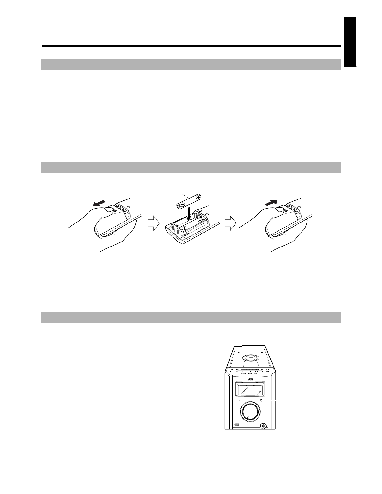
Match the polarity (+ and –) on the batteries with the + and – markings in the battery compartment.
R6P(SUM-3)/AA(15F)
CAUTION: Handle batteries properly.
To avoid battery leakage or explosion:
• Remove batteries when the Remote Control will not be used for a long time.
• When you need to replace the batteries, replace both batteries at the same time with new ones.
• Don’t use an old battery with a ne w one.
• Don’t use different types of batter ies together.
The Remote Control makes it easy to use many of the functions of the System from a distance of up to 7m (23 feet) away.
You need to point the Remote Control at the remote sensor on the System’s front panel.
Accessories
How To Put Batteries In the Remote Control
Using the Remote Control
PRESET
TUNING
BASS
CONTROL
AUX
POWER
MD/TAPE
TUNER
BAND
CD
OPEN/CLOSE
SLEEP
CLOCK
UPMULTI CONTROLDOWN
VOLUME
STANDBY
ULTRA COMPACT COMPONENT SYSTEM
FS-
8000
PHONES
Remote sensor
Page 6
3
English
CAUTION: Make all connections before plugging the System into an AC power outlet.
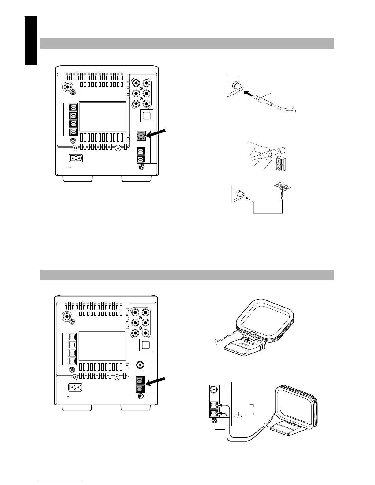
Rear Panel of the Unit
Using the Supplied Wire Antenna
Using the Coaxial Type Connector (Not Supplied)
A 75-ohm antenna with coaxial type connector should be connected
to the FM 75-ohm COAXIAL terminal.
If reception is poor, connect the outside antenna.
Note: Before attaching a 75 ohm coaxial lead (the kind with a
round wire going to an outside antenna), disconnect the supplied FM Wire Antenna.
CAUTION: To avoid noise, keep antennas away
from the System, the connecting cord and the AC
power cord.
Rear Panel of the Unit
Connecting the FM Antenna
AC IN
R
L
FM wire antenna (supplied)
Coaxial cable
FM outdoor antenna
(option)
Connecting the AM Antenna
AC IN
R
L
Attach the AM loop to its base by snapping the tabs on the
loop into the slot in the base.
AM loop antenna (Supplied)
AM EXT
AM LOOP
Turn the loop until you have the best reception.
Page 7
4
English
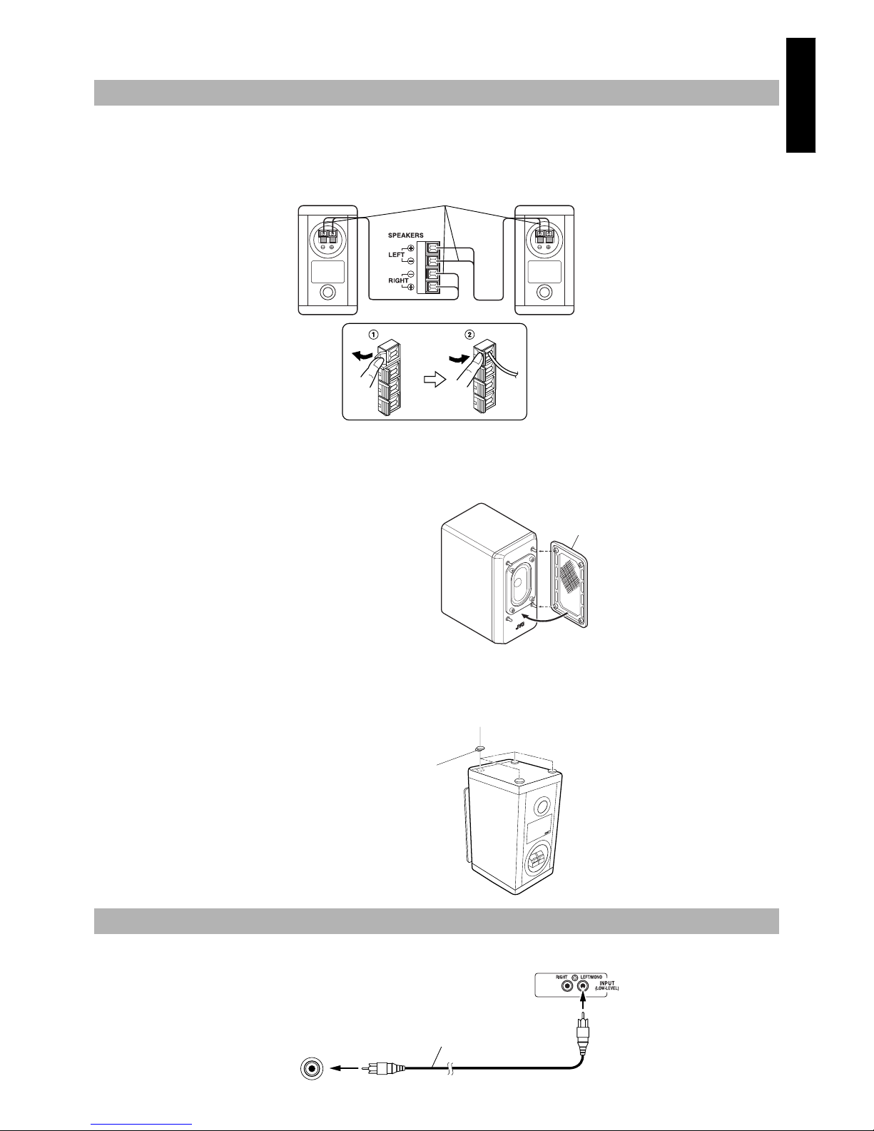
CAUTION: Make all connections before plugging the System into an AC power outlet.
1. Open the Speaker terminals on the rear of the Unit, and on the Speakers themselves.
2. Connect the speaker cords be tween the terminals as shown below.
Connect the cords with a black line to the (–) terminals and cords without a black line to the (+) terminals.
Close each of the terminals to securely connect the cords.
Right speaker (rear side) Left speaker (rear side)
CAUTION: A TV may display irregular colors if located near the speakers. If this happens, set the speakers away from the TV.
Removing the speaker grilles
The speaker grilles can be removed.
When attaching the speaker grille
When removing,
1. Insert your fingers at the top a nd pull towards you.
2. Also pull the bottom towards you.
CAUTION: Note for installation
• Take special care to select an appropriate installation place where an earthquake or shock does not cause the unit to collapse or drop on the
floor.
SP-FS8000
Attach the supplied spacers to the bottom of the unit
to protect the cabi net, prevent sli pping, and ab sorb the
cabinet vibratio n.
Peel off the backing from a spacer and at tach it.
Connect the signal cord between the SUB WOOFER OUT terminal of the Unit and the LEFT/MONO INPUT terminal of the Powered Subwoofer.
Connecting the Speakers
Connecting the Powered Subwoofer
Marked with a black line
SPEAKER CORD
Speaker grille
Spacer
Backing
SUB
WOOFER
OUT
Powered Subwoofer
Signal cord
Page 8

5
English
CAUTION: Make all connections before plugging the System into an AC power outlet.
Connect (optional) signal cords between the Sy stem’s MD/TAPE IN/OUT terminals and the output/inpu t terminals of the external MD recorder,
tape deck, etc.
You can then listen to the external source through the System, or record the System’s CD player or tuner to the external unit.
Connect an (optional) signal cord between the AUX terminals on the System and the output terminals o f your auxiliary equipmen t, (e.g. turntable). You can listen to this source.
Unplug the cap and conne ct an (op tio nal) o p tic al digital cord between the Syste m’s OPTICAL DIGITAL OUT terminal and the inpu t terminal
of the MD recorder, etc.
You can record the digital output signal from the System’s CD Player to the MD recorder, etc.
Firmly insert the supplied AC power cord i nto the AC inlet on the
back of the Unit.
The provided AC power cord fo r this u nit has ce rtain on e-way d irection connections to pre vent electric shoc k. Refer to the illustra tion for correct connection.
CAUTIONS:
• ONLY USE THE JVC POWER CORD PROVIDED WITH THIS SYSTEM TO AVOID MALFUNCTION OR DAMAGE TO THE SYSTEM.
• BE SURE TO UNPLUG THE POWER CORD FROM THE OUTLET WHEN GOING OUT OR WHEN THE SYSTEM IS NOT IN USE FOR AN EXTENDED PERIOD OF TIME.
Now you can plug the AC power cords of the Unit and the Powered Subwoofer into the wall
outlets, and your System is at your command!
Connecting an MD Recorder/Tape Deck
Connecting Auxiliary Equipment
Connecting an MD Recorder, etc (Digital Output)
Connecting the AC Power Cord to the Unit
R
L
IN
OUT
MD/TAPE
Signal cord (optional)
MD recorder o r t a pe d eck (o pti o n al)
Pin-plug x 2
Pin-plug x 2
Pin-plug x 2
Pin-plug x 2
Signal cord (optional)
R
L
AUX
Turntable (with built-in equalizer)
(optional)
Signal cord (optional)
Pin-plug x 2
Pin-plug x 2
OPTICAL
DIGITAL
OUT
MD recorder, etc. (optional)
Cap
Optical digital cord (optional)
AC IN
Power cord
Page 9

6
English
JVC’s COMPU PLAY feature lets you control the most frequently used System functions with a single touch.
With One Touch Operation you can play a CD, turn on the radio, or listen to an extern al equipmen t with a single press of the play butt on fo r
that function. One Touch Operation turns the power on for you, then starts the function you have specified. If the System is not ready (no CD
in place), the System still powers on so you can insert a CD.
How One Touch Operation works in each case i s explained in the section dealing wi th that function.
The COMPU PLAY buttons are:
■■
Common Operations
COMPU PLAY
On the Unit
CD 38 button
TUNER BAND button
MD/TAPE button
AUX button
On the Remote Control
CD 38 button
TUNER BAND button
MD/TAPE button
AUX button
PRESET
TUNING
BASS
CONTROL
AUX
POWER
MD/TAPE
0 dB
VOLUME GAIN SELECTOR
TUNER
BAND
CD
OPEN/CLOSE
TIMER/
SNOOZE
CLOCKUPMULTI CONTROLDOWN
U
L
T
R
A
C
O
M
P
A
C
T
C
O
M
P
O
N
E
N
T
S
Y
S
T
E
M
F
S
-
8
0
0
0
-6dB -12dB
SUBWOOFER
LEVEL
VOLUME
CD
TUNER
BAND
MD
/TAPE
DOWN
SET
UP
TREBLE CANCELBASS
RANDOM REPEATPROGRAM
AUTO
PRESET
VOLUME
GAIN SELECT
CD
FM MODE AUXDISPLAY
SLEEP POWERDIMMER
REMOTE CONTROL RM-RXFS8000
VOLUME
STANDBY
ULTRA COMPACT COMPONENT SYSTEM
FS-8000
PHONES
STANDBY
indicator
PHONES
VOLUME
DIMMER
DISPLAY
BASS
TREBLE
VOLUME+,–
VOLUME GAIN
SELECTOR
CLOCK
VOLUME GAIN
SELECT
Volume
illumination
POWER
POWER
BASS
CONTROL
Turning the System On ——————
Press the POWER button.
The display comes on and the STANDBY indicator goes out.
The System comes on ready to continue in the mode it was in when
the power was last turned off.
■ For example, if the last thing you were doin g was listening to a
CD, you are now ready to listen to a CD again. If you wish, you
can change to another source.
■ If you were listening to the Tuner last, the Tu ner comes on play-
ing the station it was last set to.
Turning the System Off ——————
Press the POWER button again.
The STANDBY indicator lights up and the display is blank, except
for the clock display.
■ Some power is always consumed ev en though power is turned
off (called Stan dby Mode).
■ To switch off the System completely, unplug the AC power
cord from the AC outlet. When you unplug the AC power cord,
the clock will be reset to AM 12:00 after about 20 minut es, and
preset Tuner stations will be erased after a bout 24 hours.
You can adjust the brightness of the display.
To make the display brighter, press the DIMMER button on
the Remote Control.
To make the display darker, press the DIMMER button on the
Remote Control again.
• The brightness of the volume illumination is also adjusted.
■ In Standby mode, the normal brightness is the same as the dark-
er brightness for the powered System. When you press the DIMMER button in Standby mode, the brightness becomes further
darker.
In standby mode, the volume illumination does not light.
Turning the Power On and Off
STANDBY
POWER
STANDBY
POWER
Adjusting the Brightness
(DIMMER)
Page 10

7
English
Turn the VOLUME control of the Unit clockwise to increase the
volume or counterclockwise to decrease it.
OR
With the System turned on, press the VOLUME + button on the Remote Cotrol to increase the volume or p ress the VOLUME – butto n
to decrease it.
CAUTION: DO NOT turn on the System and/or
start playing any source without first setting the
VOLUME control to minimum, as a sudden blast of
sound could damage your hearing, speakers and/
or headphones.
For private listening
Connect a pair of headphones to the PHONES jack. No sound
comes out of the speakers.
Be sure to turn down the volume before connecting or putting on
headphones.
You can lower the subwoofer and L/R sp eaker leve l (at 100Hz) as
required. (about 6 dB)
The “BASS” indicator on the display of the Unit shows the status of
this setting.
“BASS” ON: Normal level
“BASS” OFF: Level lowered
Each time you press the BASS CONTROL button on the Unit, the
subwoofer and L/R speaker level is lowered or returned to the normal level.
You can control the tone by changing the bass and treble.
BASS Control ———————————
You can adjust the bas s level ( low frequ ency ra nge leve l) be tween
–6 and 6. (0: Flat)
■
1. Press the BASS button on the Remote Control.
■
2. Press the UP or DOWN button on the
Remote Control to adjust the bass level.
TREBLE Control ——————————
You can adjust the treble level (high freq uency range level) betwee n
–6 and 6. (0: Flat)
■
1. Press the TREBLE button on the Remote
Control.
■
2. Press the UP or DOWN button on the
Remote Control to adjust the treble level.
This lets you adjust the range covered by the VOLUME control.
This is useful if you rarel y list en at hi gher volu mes , and want fin er
control over lower volumes. There are three volume gain settings:
0 dB: Normal volume.
–6 dB: The volume adjustabl e ra ng e is ex tended for lower
level. You can finely adjust the volume level than
that for “0 dB”.
–12 dB: The volume adjustable range is further extended for
lower level. You can finely adjust the vol ume le vel
than that for “–6 dB”.
Example:
Press the 0 dB, –6 dB, or –12 dB button on the Unit, or
press the VOLUME GAIN SELECT button on the Remote
Control to make your selection.
The following appears on the display for 2 seconds:.
• Volume Gain Selection
When you change the volume gain with the VOLUME GAIN
SELECT button, the VOLUME control auto matic a lly turns so
that the volume level is kept almost the same.
Note:
• If you change the volume gain while listening to a music
source, the sound may be muted for a few seconds before the
new volume gain selection comes into effect. This happens in
the following cases:
• Changing from the –12 dB selection to the –6
dB or 0 dB selections.
• Changing from the –6 dB selection to the 0 dB
selection.
In addition to a standard d igital cloc k, an analog ue clock (which advances every fi ve minutes) can be displayed. The clock display order varies according to the System mode:
In Standby mode ——————————
Every time you press the DISPLAY button on the Remote Control
(or the CLOCK button on the Unit), the clock display changes as
shown below.
Digital Clock + Analogue Clock
= Analogue Clock = Digital
Clock
= (back to the beginning)
When the System is turned on ———
Every time you press the DISPLAY button on the Remote Control
(or the CLOCK button on th e Unit), the time displ ay changes as fo llows:
Current Source + Analogue Clock
= Analogue Clock = Digital
Clock
= Current Source = (back to the beginning)
Note: To let work the clock, you need to set the clock beforehand.
(See “Setting the Clock” on page 14.)
Adjusting the Volume
Lowering the Subwoofer and
L/R Speaker Level
Tone Control (BASS/TREBLE)
Volume Gain Selection
Showing the Time (DISPLAY)
MinAMax MinAMax MinAMax
A: Volume level range you
usally use.
(0 dB)
Volume adjustable range for “A” is extended.
(–6 dB) (–12 dB)
Page 11

8
English
■■
Using the Powered Subwoofer
VOLUME
PHASE
POWER
INPUT (LOW-LEVEL)
INPUT (HIGH-LEVEL)
AUTO POWER
ON/STANDBY
indicator
Presetting the Volume ———————
You need to preset the volume level of this speaker to match those
of the other speakers. Once you preset the volume level, it is stored
as your referenc e level and the volume level of this speaker will be
able to automatically change as the volu me leve l of the Unit c hanges.
■
1. Press the POWER button of the Subwoofer
to turn on the power.
The ON/STANDBY indicator of the Subwoofer will light in
green.
■
2. Set the VOLUME in the “MIN” position.
■
3. Adjust the volume of the Unit to your listening level.
■
4. Adjust the VOLUME to balance the volume
with the other speakers.
To turn off the Subwoofwer, press the POWER switch to light
off the ON/STANDBY indicator.
Note: When adjusting the VOLUME, be sure the “BASS” indica-
tor on the Unit is lit, indicating that the subwoofer level is
set to normal. If not, press the BASS CONTROL button on
the Unit to light it up.
Adding the Richness to the Bass
(PHASE) ——————————————
If you want to add the richness m ore to the bass , press the PHASE
button to set it either in the “
_ REVERSE” position or the “— NOR-
MAL” position, whichever can add the richness to the bass.
Normally, the PHASE button should be set in the “— NORMAL”
position.
Automatic Operating Status On/Off
To save energy, the Subwoofer enter s the Standby mod e if no (or
very weak) sound signals come into the Subwoofer for about 5 minutes. In Standby mode, the ON/STANDBY indicator of the Subwoofer lights in red.
When sound signals come in again, the Subwoofer enters the Operating mode and reproduces the sounds. The ON/STANDBY indicator will light in gre e n again.
CAUTION: Be sure to turn off the POWER of the
Powered Subwoofer when the Powered Subwoofer is not in use for an extended period of time.
INPUT Terminals ——————————
The Subwoofer has the following INPUT terminals.
INPUT(LOW-LEVEL):
Usually, the LEFT/MONO terminal is connected to the SUBWOOFER OUT terminal of the Unit with the supplied signal cord.
(see page 4)
Operating the Powered
Subwoofer
When CA-FS8000 is not used
(Using other equipment)
If an unit to be connected does not have the SUB WOOFER
OUT terminals, the RIGHT and LEFT/MONO terminals will
be connected to the LINE OUT-RIGHT and LEFT terminals o f
that unit.
INPUT (HIGH-LEVEL):
You can connect the spea ker output term inals of other unit to
these terminals.
Connect the speaker co rds in parallel t o the speak er terminals
on the component system etc.
Note: Do not use the INPUT (LOW-LEVEL) terminals at the
same time.
LINE OUT
LEFTRIGHT
Connecting cord
(not supplied)
AMP
SPEAKER
LEFTRIGHT
Component
System
etc.
Speaker cords
(not supplied)
Page 12

9
English
■■
Using the Tuner
Band display, Frequency display,
Preset channel
FM mode indicators
SUBWOOFER
LEVEL
VOLUME
CD
TUNER
BAND
MD
/TAPE
DOWN
SET
UP
TREBLE CANCELBASS
RANDOM REPEATPROGRAM
AUTO
PRESET
VOLUME
GAIN SELECT
CD
FM MODE AUXDISPLAY
SLEEP POWERDIMMER
REMOTE CONTROL RM-RXFS8000
<
FM MODE
DOWN
¢
4
AUTO PRESET
UP
>
SET
TUNER BAND
PRESET
TUNING
BASS
CONTROL
AUX
POWER
MD/TAPE
0 dB
VOLUME GAIN SELECTOR
TUNER
BAND
OPEN/CLOSE
TIMER/
SNOOZE
CLOCKUPMULTI CONTROLDOWN
U
L
T
R
A
C
O
M
P
A
C
T
C
O
M
P
O
N
E
N
T
S
Y
S
T
E
M
F
S
-
8
0
0
0
-6dB -12dB
CD
TUNER BAND
4
¢
PRESET TUNING
When the System is in use, the display shows other items as well.
For simplicity, we show here only the items described in thi s sectio n.
You can listen to FM and AM stations. Stations can be tuned in
manually, automatically, or from preset memory storage.
■ Before listening to the radio:
• Check that both the FM and AM antennas are correctly con-
nected. (See page 3).
One Touch Radio —————————
Just press the TUNER BAND button to turn on the System and start
playing the station you were last tuned to.
■ You can switch from any other sound source to the radio by
pressing the TUNER BAND button.
■
1. Press the TUNER BAND button.
The Band and Frequency you were last tuned to appear on the
display.
(If the last station was selected using the preset number, the preset number appears first.)
Each time you press the button, the band alternates betwe en FM
and AM.
■
2. Select a station using one of the following
methods.
■ Manual Tuning
Press the
4 or ¢ button on the Unit or the Remote Control
repeatedly to move from freque ncy t o freq uency un til y ou fin d
the station you want.
OR
■ Auto Tuning
If you press and hold the
4 or ¢ button on the Unit or the
Remote Control for one second or more, the frequency changes
down, or up, automatically until a station is found.
OR
■ Preset Tuning using the Remote Control (Possible
only after presetting stations)
Press the UP or DOWN button on the Remote Co ntrol to selec t
the desired preset number. After 1 second the displa y will show
the preset number’s band and frequency.
Example: Press the UP button until the preset number 12 “P--
12” appears.
■ Preset Tuning using the Unit (Possible only after pre-
setting stations)
Press the PRESET TUNING button to select the desired p reset
number. Its band and frequency are displayed.
You can preset up to 30 FM stations and up to 15 AM stations using
the Remote Control.
Note: Preset numbers may have been set to factory test frequen-
cies prior to shipment. This is not a malfunction. You can
preset the stations you want into mem ory by follo wing one
of the presetting methods below.
Manual Presetting —————————
■
1. Select a band by pressing the TUNER
BAND button.
■
2. Press the 4 or ¢ button to tune in a station.
■
3. Press the SET button.
“P------” is displayed. The lower 2 digits blink.
■
4. Press the UP, DOWN, >, or < button to
select the preset number.
UP button: Increases the preset number by 1.
DOWN button:Decreases the preset number by 1.
> button: Increases the tenth digit for preset number.
< button: Decreases the tenth digit for preset number.
Tuning In a Station
Presetting Stations
(After 1 second)
When Changing the
Band
Page 13

10
English
■
5. Press the SET button.
After 1 second, the display returns to the broadcast frequency
display.
■
6. Repeat above steps 1 to 5 for each station
you want to store in memory with a preset
number.
To cancel the preset ting, press the CANCEL button in step
3 or 4.
To change the preset stations, repeat the same steps as
above.
In each band, you c an autom aticall y prese t FM-30, AM-15 sta tions.
Preset numbers will be allocated as station s are found, starting fro m
the lowest frequency and moving up the frequency.
■
1. Select a band by pressing the TUNER
BAND button.
■
2. Press the AUTO PRESET button on the
Remote Control for more than two seconds.
■
3. Repeat steps 1-2 for the other band.
■ If you want to change the preset stations, carry out the Manual
Presetting for the desired preset numbers.
CAUTION: If the System is unplugged or if a power failure occurs, the preset stations will be
erased after about 24 hours. If this happens, you
will need to preset the stations again.
When you are tuned into an FM stereo broadcast, the “ST (Stereo)”
indicator lights up and you can hear stereo effects.
If an FM stereo broadcast is hard to receive or noisy, you can select
Monaural mode. Reception impro ves, but you lose any stereo effect.
Press the FM MODE button on the Remote Control so that
the “MONO” indicator lights up on the display.
To restore the ster eo effect, press th e FM MODE bu tton on the
Remote Control so that the “MONO” indicator goes off.
Auto Presetting
To Change the FM
Reception Mode
(for 2 seconds)
FM MODE
ST(Stereo) MONO
Page 14

11
English
■■
Using the CD Player
DISPLAY
MODEPTY/EON
AUX
MD/TAPE
0 dB
VOLUME GAIN SELECTOR
TUNER
BAND
CD
OPEN/CLOSE
TIMER/
SNOOZE
CLOCKUPMULTI CONTROLDOWN
U
L
T
R
A
M
I
C
R
O
C
O
M
P
O
N
E
N
T
S
Y
S
T
E
M
U
X
-
7
0
0
0
R
-6dB -12dB
PRESET
TUNING
BASS
CONTROL
AUX
POWER
MD/TAPE
0 dB
VOLUME GAIN SELECTOR
TUNER
BAND
OPEN/CLOSE
TIMER/
SNOOZE
CLOCKUPMULTI CONTROLDOWN
U
L
T
R
A
C
O
M
P
A
C
T
C
O
M
P
O
N
E
N
T
S
Y
S
T
E
M
F
S
-
8
0
0
0
-6dB -12dB
CD
SUBWOOFER
LEVEL
VOLUME
CD
TUNER
BAND
MD
/TAPE
DOWN
SET
UP
TREBLE CANCELBASS
RANDOM REPEATPROGRAM
AUTO
PRESET
VOLUME
GAIN SELECT
CD
FM MODE AUXDISPLAY
SLEEP POWERDIMMER
REMOTE CONTROL RM-RXFS8000
PROGRAM
CD
38
¢
4
<
7
DOWN
>
UP
RANDOM
REPEAT
CD
0
Play mode
Indicator
Play Indicator
Pause Indicator
Repeat Indicator
Track number, Playing time,
Preset number
CD Holder
CD
38
OPEN/
CLOSE
0
¢
7
4
SET
When the System is in use, the display shows other items as well.
For simplicity, we show here only the items described in this section.
You can use Normal, Rand om, Program or Repeat Play. Repeat
Play can repeat all the tracks or just one of the tracks on the CD.
Here are the bas ic th ing s yo u n e ed to know to play a C D an d lo c at e
the different tracks on it.
The Quickest Way To Start a CD Is With the
One Touch Operation
■ Press the CD
38
button.
• The power is automatically turned on . If a CD is already in-
serted, it will start playing from the first track.
• If no CD is inserted, “NO DISC” appears on the display and
the CD Player remains in Stop mode.
■
1. Press the OPEN/CLOSE 0 button (or the CD
0
button on the Remote Control).
The CD holder opens.
■
2. Place a CD, with its label side up as shown
below.
■
3. Press the 0 button again to close the CD
holder.
■ You can place an 8 cm (3'') CD without an adaptor.
■ If the CD cannot be read correctly (because it is scratched, for
example), “00 0000” appears on the display.
CAUTION:DO NOT try to close the CD holder by
hand as it will be damaged.
To Play a CD ————————————
■
1. Insert a CD.
■
2. Press the CD 38 button.
The Play (3) indicator lights up on the display and the first
track of the CD begins playing.
The CD Player automatically stops when the last track of the
CD has finished playing.
To stop playing the CD, press the e button on the Unit or the
Remote Control.
The following information for the CD is displayed.
To stop playing and remove the CD, press the
0 button to
open the CD holder.
To pause, press the CD
38 button. The Pa use (
8
) indicator will
light up on the display.
To cancel pause, press the same button again. Play continues
from the point where it was paused.
To Select a Track or Passage within
a Track ———————————————
During playback, press the 4 or ¢ button on the Unit or the Remote Control to select the track you want.
The selected track starts playing.
• Press the
¢ button once to skip to the beginning of the
next track.
• Press the 4 button to skip to the beginning of the tra ck being played. Press twice quickly to skip to the beginning of
the previous track.
To Insert a CD
Basics of Using the
CD Player - Normal Play
Total track number
Total playback time
Page 15

12
English
Search Play ————————————
Holding down the 4 or ¢ button on the Unit or the Remote Control, during playback, will fast forward/backwards the CD so you can
quickly find a particular passage in the track you are listening to.
You can program the play ing ord er of t he tracks us ing th e Remote
Control.
■ You can program up to 20 trac ks in an y de s ir e d or d e r.
■ You can only make a program when the CD Player is stopped.
■
1. Insert a CD.
■
2. Press the CD 38 button.
■
3. Press the e button to stop the CD.
■
4. Press the PROGRAM button.
The System enters the programming mode and the “PRGM” indicator lights up.
■
5. Press the UP, DOWN, >, or < button to
select the track to program.
UP button: Increases the track number by 1.
DOWN button: Decreases the track number by 1.
> button: Increases the the track number by ten.
< button: Decreases the track number by ten.
• Example: for track 2, press the UP button twice. For track
12, press the > button, then press the UP button twice (or
simply press the UP button 12 times).
■
6. Press the SET button.
■
7. Repeat steps 5 and 6 to select the other
tracks for the program.
You can see the total playback time of program med tracks on
the display.
■
8. Press the CD 38 button.
The System plays the tracks in the order you have programmed
them.
■ You can skip to a particular program track by pressing the 4
or
¢ button during Program Play.
To cancel the programming before play ing, press the CANCEL button in above step 4, 5 or 6.
To confirm the programmed tracks, press the PROGRAM
button; the tracks making up the pr ogram will succes sively b e displayed in the programmed order.
To stop playing, press the e button once .
To delete all the tracks in a program, press the e button (or
the CANCEL button on the Remote Control) while the CD Player
is stopped. The “PRGM” indicator goes out and the program is deleted. Normal Play is resumed.
The program will also be deleted when you press the
0 button to
open the CD holder.
Note: If the total playback time of the programmed track s exceeds
99 minutes 59 seconds, the total playback time will go out
on the display.
The tracks will play in no special order when you use this mode.
Press the RANDOM button on the Remote
Control.
Playback automatically starts and the “RADM” indicator lights up
on the display.
To skip a track during playba ck, press the ¢ button to ju m p
to the next track in the random seq uence. Press the
4 button to
jump back to the start of a track being played.
To cancel random play, press the RANDOM button again. The
“RADM” indicator goes out and Normal Pl ay is resumed.
You can set the program or individual track playing to repeat as
many times as you like.
Press the REPEAT button on the Remote
Control.
The Repeat indicator changes with each press of the button, as
shown below.
= ALL =blank display = (back to the beginning)
: Repeats one track.
In Random Play mode, this indicator is skipped.
ALL : In Normal Play mode, repeats all the tracks.
In Program Play mode, repeats all the tracks in the
program.
In Random Play mode, repeats all the tracks in random order.
To exit Repeat mode, press the REPEAT button until the Re peat
indicator on the display goes out
Programming the
Playing Order of the Tracks
PROGRAM
Total playback time of the programmed tracks.
Random Play
Repeating Tracks
Programme order numbe r
Track number
Page 16

13
English
■■
Listening to External Equipments
PRESET
TUNING
BASS
CONTROL
AUX
POWER
MD/TAPE
0 dB
VOLUME GAIN SELECTOR
TUNER
BAND
OPEN/CLOSE
TIMER/
SNOOZE
CLOCKUPMULTI CONTROLDOWN
U
L
T
R
A
C
O
M
P
A
C
T
C
O
M
P
O
N
E
N
T
S
Y
S
T
E
M
F
S
-
8
0
0
0
-6dB -12dB
CD
SUBWOOFER
LEVEL
VOLUME
CD
TUNER
BAND
MD
/TAPE
DOWN
SET
UP
TREBLE CANCELBASS
RANDOM REPEATPROGRAM
AUTO
PRESET
VOLUME
GAIN SELECT
CD
FM MODE AUXDISPLAY
SLEEP POWERDIMMER
REMOTE CONTROL RM-RXFS8000
AUX
MD/TAPE
AUX
MD/TAPE
You can play an external MD record er, tape d eck, etc. thro ugh the
system.
■ First make sure that the external equipment is properly co nnect-
ed to the System. (See page 4.)
■
1. Set the VOLUME control to minimum.
■
2. Press the MD/TAPE button.
When the System is in Standby mode, the System is automati cally turned on.
“MD/TAPE” appears on the display.
■
3. Start playing the external equipment.
■
4. Adjust the VOLUME control to the desired
listening level.
■
5. Apply sound effects, if you wish.
■ Press the BASS CONTROL button to reinforce the bass sound.
■ Press the BASS/TREBLE button to control the tone. (See “Tone
Control” on page 7.)
To exit MD/TAPE mode
You will automatically switch out of MD/TAPE m ode when you select another source.
Note: You can also record t he Sys tem’s outpu t sign al to the ext er-
nal equipment. For operation, refer to the equipment’s own
instructions.
You can listen to a turntable or other auxiliary equipment.
■ First make sure that the external equipment is properly co nnect-
ed to the System. (See page 5.)
■
1. Set the VOLUME to minimum position.
■
2. Press the AUX button.
When the System is in Standby mode, the System is automati cally turned on.
“AUX” appears on the display.
■
3. Start playing the auxiliary equipment.
■
4. Adjust the VOLUME control to the desired
listening level.
■
5. Apply sound effects, if you wish.
■ Press the BASS CONTROL button to reinforce the bass sound.
■ Press the BASS/TREBLE button to control the tone. (See “To ne
Control” on page 7.)
To exit AUX mode
You will automatically switch out of AUX mode when you select
other source.
Note: For operation of the auxiliary equipment, refer to its own In-
structions.
Listening to an External MD
Recorder/Tape Deck
Listening to Auxiliary Equipment
Page 17

14
English
■■
Using the Timers
PRESET
TUNING
BASS
CONTROL
AUX
POWER
MD/TAPE
0 dB
VOLUME GAIN SELECTOR
TUNER
BAND
OPEN/CLOSE
TIMER/
SNOOZE
CLOCKUPMULTI CONTROLDOWN
U
L
T
R
A
C
O
M
P
A
C
T
C
O
M
P
O
N
E
N
T
S
Y
S
T
E
M
F
S
-
8
0
0
0
-6dB -12dB
CD
SUBWOOFER
LEVEL
VOLUME
CD
TUNER
BAND
MD
/TAPE
DOWN
SET
UP
TREBLE CANCELBASS
RANDOM REPEATPROGRAM
AUTO
PRESET
VOLUME
GAIN SELECT
CD
FM MODE AUXDISPLAY
SLEEP POWERDIMMER
REMOTE CONTROL RM-RXFS8000
Timer indicator
SLEEP
4
¢
CLOCK
TIMER/
SNOOZE
SLEEP indicator
SNZ indicator
When the System is in use, the display shows other items as well.
For simplicity, we show here only the items described in this section.
The timers let you control listening functions automatically.
You can set the clock whether the System is on or off.
Notes:
• The clock must be correctly set for the timers to work.
• The procedure must be completed within two minutes. Otherwise,
the setting is cleared and must be repeated from the beginning.
■
1. Press the CLOCK button on the Unit for
more than two seconds.
The clock rapidly blinks.
■
2. Press the 4 or ¢ button on the Unit to set
the time.
Pressing the ¢ button moves the time forwards and pressing
the
4 button moves it backwards. Hold down the button to
move the time in 10-minute intervals.
■
3. Press the CLOCK button.
The selected time is set and the seconds start counting from 0.
• Each time the hour’s digits change from 11 to 12, the dis-
play alternates between AM and PM. (12 midnight is indicated as “AM 12:00” and 12 noo n is indicated as “PM
12:00”.)
CAUTION: If there is a power failure, the clock
loses its setting after about 20 minutes. The display shows “AM 12:00” and blinks, and the clock
must be reset.
Note: The clock may gain or lose one to two minu tes per month.
You can set the Timer whether the System is on or off.
Once you have set the Daily Timer, the timer will be activated at the
same time every day. It can be cancelled and re-activated whenever
you wish.
The Timer indicator on the di splay shows when the Daily Time r you
have set is in effect.
Note: Perform each setting within 30 seconds. Otherwise, the set-
ting is cleared and the procedure must be repeated from the
beginning.
■
1. Press the POWER button to turn on the System.
■
2. Setting the ON time (Example: PM 12:15).
1. Press the TIMER/SNOOZE button on the Unit.
The Timer indicator lights up and the current ON time
blinks on the display.
2. Press the
¢ or 4 button on the Unit to set the time you
want the Unit to come on.
Pressing the ¢ button moves the time forwards and pressing the
4 button moves the time backwards. Hold down
the button to move the time in 10-minute intervals.
Setting the Clock
UPMULTI CONTROLDOWN
(for 2 seconds)
Setting the Daily Timer
(After 2 seconds)
Page 18

15
English
■
3. Setting the OFF time (Example: PM 1:15).
1. Press the TIMER/SNOOZE button on the Unit.
The current OFF time blinks on the display.
2. Press the ¢ or 4 button on the Unit to set the time you
want the Unit to be turned off.
Pressing the ¢ button moves the time forwards and pressing the
4 button moves the time backwards. Hold down
the button to move the time in 10-minute intervals.
■
4. Selecting the music source.
1. Press the TIMER/SNOOZE button on the Unit.
“TUNER” blinks on the display.
2. Press the ¢ or 4 button to select the music source you
want to listen to.
The display changes as shown below.
■
5. Setting the volume level.
1. Press the TIMER/SNOOZE button on the Unit.
The current volume setting blinks on the display.
2. Press the ¢ or 4 button to select the volume level
-- : The current volume level will be used.
1 to 5: Low (1) to high (5) level. When the timer is turned
on, the Volume will be automatically turned to the
set position.
Note: The volume level for VOL1 to VOL5 will vary accordin g to
the current volume gain selection (0 dB, –6 dB or –12 dB).
So, you should learn the actual volume level beforehand.
■
6. Press the TIMER/SNOOZE button on the
Unit.
The timer setting is completed and the displa y returns to the display before you set the timer (The Timer indicator remains lit).
■
7. Before turning off the Unit, prepare the
music source selected in step 4.
Tuner: Tune in to the desire d station.
CD: Insert a CD.
■
8. Press the POWER button to turn off the
System.
To cancel th e timer, press the TIMER/SNOOZE button. The
Timer indicator goes out on the display.
To re-activate the cancelled timer, press the TIMER/
SNOOZE button to light the Timer indica to r. The n, pre ss the TIMER/SNOOZE button repeatedly until the display returns to the o riginal display before setting the timer. (Be sure that the Timer
indicator is lit)
To confirm the timer settings, cancel the timer once by pressing the TIMER/SNOOZE button. Then, press the TIMER/
SNOOZE button repeatedly, and you can see the current timer settings (ON time, OFF tim e , source, and volume).
To change the timer setting, repeat the setting procedure from
the beginning.
• When the timer turns on, the Timer indicator starts blinking.
• When the timer turns o n, it is po ssible to fade in the sound f rom
volume level 0 (zero) to the preset volu me .
CAUTION: If the System is unplugged, or a power
failure occurs, the timer setting will be lost after
about 24 hours. You will need to reset the clock
first, then the timer.
5-Minute Snoozing——————————
When the timer turns on the music source you can, if you wish, activate the 5-minute snoozing function to temporarily stop playback.
Press the TIMER/SNOOZE button on the Unit.
The “SNZ” indicator lights up on the display and the power is
turned off for five minutes for snoozing.
Use the Sleep Timer to turn the System off after a certain number of
minutes when it is playing. By setting the Sleep Timer, you can fall
asleep to music and know that your System will turn off by itself
rather than play all night.
■ You can only set the Sleep Timer when the System is on and a
source is playing.
■
1. Play a CD or tune in to the desired station.
■
2. Press the SLEEP button on the Remote
Control.
The “SLEEP” indicator lights up.
■
3. Set the length of time you want the source
to play before shutting off.
• Each time you press the SLEEP button, it changes the
number of minutes shown on the display in this sequence:
= 30 = 60 = 90 = 120 = Cancelled = (back to the be gin-
ning)
After setting the number of minute s for the Sleep Timer, the disp lay
will stop blinking after 5 seconds and return to the display as before
setting the Sleep Timer.
The System is now set to turn off after the number of minutes you
set.
To Confirm the Sleep Time
When the SLEEP button is pressed, the remaining sleep time is displayed. Wait for 5 seconds until the display returns to the original
display.
To Cancel the SLEEP Timer Setting
Press the SLEEP button until the “SL EEP” indicat or goes off on the
display.
Turning off the System also cancels the SLEEP Time r.
■ If you are setting the Daily Timer, the System will be turned on
at the set time to wake you up.
(After 2 seconds)
V
OL 1
VOL 5
VOLUME
VOL 5: Approx. 11 o’clock position
VOL 1: Approx. 8 o’clock position
Setting the SLEEP Timer
Page 19

16
English
■■
Care And Maintenance
Handle your CDs carefully, and they will last a long time.
Compact Discs
• Only CDs bearing this mark can be used with
this System. However, continued use of irregular shape CDs (heart-shape, octagonal, etc.)
can damage the Syst em.
• Remove the CD from its case by holding it at
the edges while pressing the case’s center hole
lightly.
• Do not touch the shiny su r f a c e of the CD, or
bend the CD.
• Put the CD back in its case after use to prevent
warping.
• Be careful not to scratch the surface of the CD
when placing it back in the case.
• Avoid exposure to direct sunlight, temperature
extremes, and moisture.
• A dirty CD may not play correctly. If a CD
does become dirty, wipe it with a soft cloth in a
straight line from center to edge.
CAUTION: Do not use any solvent (for example,
conventional record cleaner, spray thinner, benzine, etc.) to clean a CD.
Moisture Condensation
Moisture may condense on the lens inside the
System in the following cases:
• After turning on heating in the room.
• In a damp room.
• If the System is brought directly fr om a cold
to a warm place.
Should this occur, the System may malfun ction.
In this case, leave the System turned on for a
few hours until the moisture evaporates, unplug
the AC power cord, and then plug it in again.
General Notes
In general, you will have the best performance by keeping your CDs
and the mechanism clean.
• Store CDs in their cases, and keep them i n cabinets or on
shelves.
• Keep the system’s CD holder closed when not in use.
Cleaning the lens
If the lens in the CD pickup is dirty, dropout, etc., could degrade
sound.
Open the CD holder and clean the lens as shown.
• Use a blower (available from a camera store) to blow dust off
the lens.
• If there are fingerprints, etc. on the lens, gently wipe clean with
a cotton swab.
Blower
Lens
Page 20

17
English
■■
Troubleshooting
• If you are having a problem with your System, check this list for a possible solution before calling for service.
• If you cannot solve the problem from the hints given here, or the System has been physically damaged, call a qualified person, such as
your dealer, for service.
Symptom Possible Cause Action
No sound is heard. • Connections are incorrect, or lo ose.
• Headphon es are connect ed.
• Check all connections and make corrections. (See pages 4- 5.)
• Disconnect the headp hones.
Poor radio reception • The antenna is disconnected.
• The AM Loop Antenna is too close to
the System.
• The FM Wire Antenna is not properly
extended and positioned.
• Reconnect the antenna securely.
• Change the position and direction of the
AM Loop Antenna.
• Extend FM Wire Antenna to the best
reception position.
The CD skips. The CD is dirty or scratched. Clean or replace the CD.
The CD does not pla y. The CD is upside down. Put the CD in with the label side up.
Unable to operate the Remote Control. • The path between the Remote Control
and the sensor on t he Unit is blocked
• The batteries have lost their charge.
• Remove the obst ruc tion.
• Replace the batteries.
Operations are disabled. The built-in microprocessor has malfunc-
tioned due to external electrical in terfe renc e.
Unplug the System then plug it back in.
Subwoofer automatically turns on, but no
sound is output.
The volume knob of the Subwoofer is set to
MIN position.
Adjust the volume knob.
Subwoofer does not automatically turn on. The volume knob of the Subwoofer is set to
MIN position. Also, the volume level of
CA-FS8000 is low.
Adjust both volume levels
Page 21

18
English
■■
Specifications
(CA-FS8000)
Amplifier
Output Power 13 watts per channel, mi n. RMS, a t 4 ohms f rom 110 Hz to 20 kH z, with no more than 10%
total harmonic distortion (for U.S.A.)
30 W (15 W + 15 W) at 4 ohms (Max.) (for Canada)
Input Sensitivity/Impedance (1 kHz)
AUX 500 mV/59 kohms
MD/TAPE 500 mV/59 kohms
Output Sensitivity/Impedance (1 kHz)
MD/TAPE 500 mV/4.9 kohms
Optical out –21 dBm - –15 dBm
Subwoofer 0 - 155 mV/10 kohms
Speaker terminals 4 - 16 ohms
Phones 16 ohm - 1 kohms
0 - 15 mW/ch outp ut into 32 ohms
CD Player
Signal-To-Noise Ratio 90 dB
Wow And Flutter Unmeasurable
Tuner
FM Tuner
Tuning Range 87.5 - 108.0 MHz
AM Tuner
Tuning Range 530 - 1,710 kHz
Power Specifications
Power Requirements AC 120 V ~ , 60 Hz
Power Consumption 30 watts (power on mode)
5 watts (in Standby mo de)
Dimensions 140
✕
164 ✕ 298 mm (W/H/D)
(5 –
9
/16" ✕ 6 – 1/2" ✕ 11 – 3/4")
Mass Approx. 3.1 kg (6.9 lbs)
Speaker Specifications
(SP-FS8000)
(each unit)
Speakers 7 cm (
5
/16") ✕ 4 cm (3/16") Track-type cone
Impedance 4 ohms
Dimensions 85 ✕ 158 ✕ 116 mm (W/H/D)
(3 –
3
/8" ✕ 6 – 1/4" ✕ 4 – 5/8")
Mass Approx. 0.6 kg (1.4 lbs)
Powered Subwoofer
(SP-PW8000)
Speaker Woofer 20 cm (7 –
7
/8") (4 ohms) ✕ 1
Rated Impedance 4 ohms
Frequency Response 40 - 125 Hz
Output sound pressure level 85 dB/W-m
Input sensitivity/Impedance
LOW LEVEL 80 mV/50 kohms
HIGH LEVEL 2.1 V/4 ~ 16 ohms
Output Power 60 watts, min. RMS, at 4 ohms from 40 Hz to 125 Hz, with no more than 10% total har-
monic distortion (for U.S.A.)
90 W at 4 ohms (MAX.) (for Canada)
Power requirements AC 120 V ~, 60 Hz
Power consumptions 31 W
Dimensions 270
✕
330 ✕ 410 mm (W/H/D)
(10 –
11
/16" ✕ 13" ✕ 16 – 3/16")
Mass 9.2 kg (20.3 lbs)
Accessories
Power Cord (1)
AM Loop Antenna (1)
Remote Control (1)
Batteries R6P (SUM-3)/AA (15F) (2)
FM Wire Antenna (1)
Speaker Cords (2)
Signal Cord (1)
Spacers for SP-FS8000 (8)
Design and specifications are subject to change without notice.
Page 22

VICTOR COMPANY OF JAPAN, LIMITED
EN, FR 0599MNMCREJSC
 Loading...