

Page 1
EnglishFrançaisEspañol
TK-C205
INSTRUCTIONS
MODE D’EMPLOI
INSTRUCCIONES
For Customer Use:
Enter below the Serial No. which is
located on the body. Retain this
information for future reference.
Model No. TK-C205
Serial No.
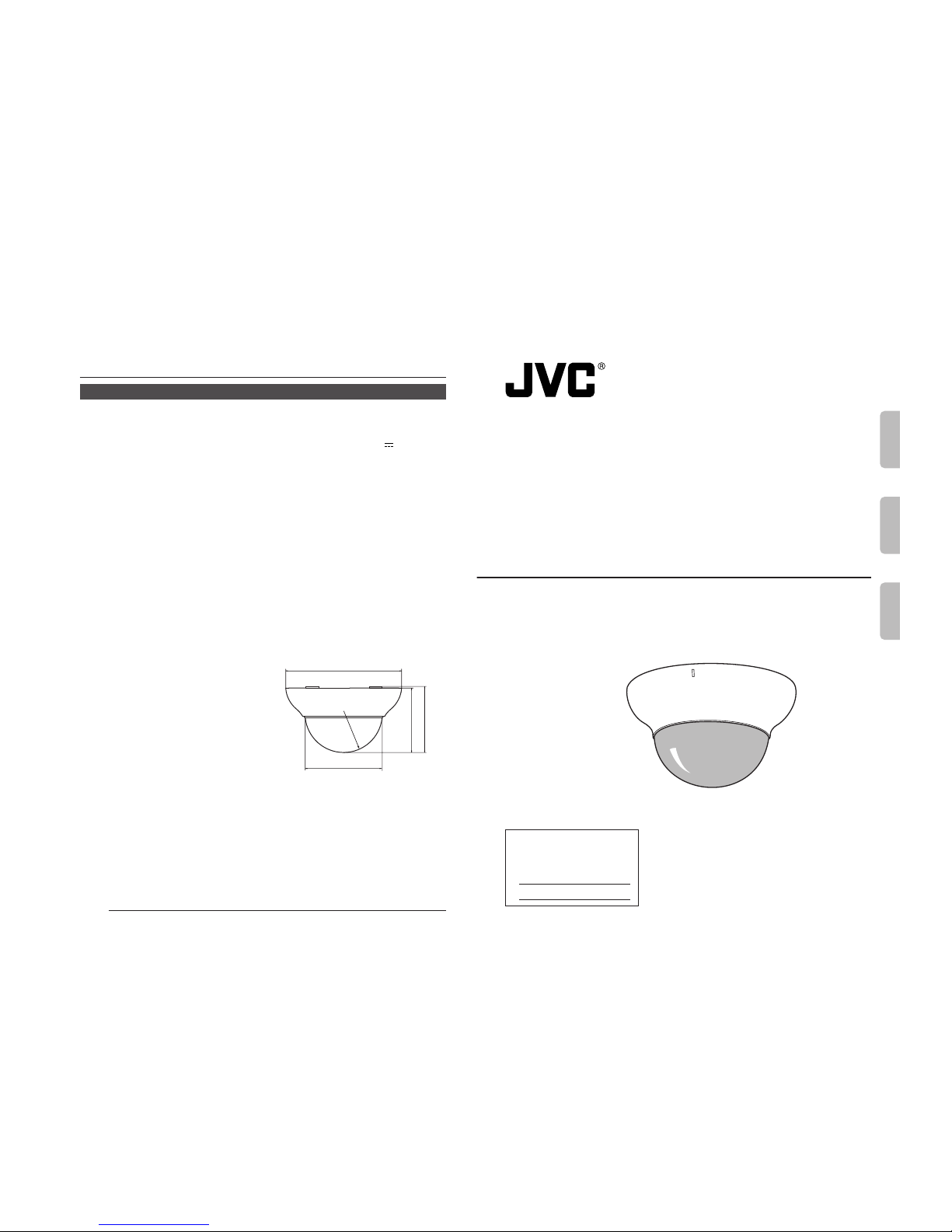
DOME CAMERA
CAMÉRA À DÔME
CÁMARA DOMO
LWT0123
E-16
CAMERA
Signal system:
U type based on NTSC standard
E type based on PAL standard
Image device: 1/4” IT CCD
Effective picture elements:
U type 380,000 pixels,
768 (H) × 494 (V)
E type 440,000 pixels,
752 (H) × 582 (V)
Sync system: Line lock/Internal
Video S/N: 50 dB (AGC OFF, Typ.)
Horizontal resolution:
535 TV lines (Typ.)
Minimum illumination:
4.8 l× (F1.2, AGC ON,
50%, WIDE end) (Typ.)
2.4 l× (F1.2, AGC ON,
25%)
0.9 l× (F1.2, AGC ON,
25%, with clear dome
cover (option))
White balance: ATW/Manual (switchable)
ATW: Color temperature range
2300K to 10000K.
Backlight compensation:
ON/OFF (Switchable)
LENS
Focal length: 2.6 mm to 6 mm (variable)
Max. aperture ratio:
F1.2 to F1.8
Angle of vision:
f = 2.6 mm
82° (H) × 59° (V)
f = 6 mm
35° (H) × 26° (V)
Angle adjustment range:
Horizontal: 120°
Vertical: +80°, –50°
Tilt: ±15°
SPECIFICATIONS
GENERAL
Power requirement:
AC 24 V ` 50/60 Hz or
DC 12 V
Power consumption:
U type Approx. 4.2 W
E type Approx. 300 mA
Mass: 570 ˝
Operating temperature:
–10°C to 50°C (recommended: 0°C to 40°C)
Dimensions: Approx. 156 mm diam-
eter × 89 mm
Accessories:
U type E type
• Instructions × 1 • Instructions × 2
• Warranty card × 1
• Service information
card × 1
External dimensions
[Unit: inches (mm)]
• Design and specifications are subject to
change without notice.
φ6-3/16(156)
φ4-3/32 (103.5)
3-7/16(87)
3-9/16(89)
SR2-1/16(52)
Others
Page 2

I
IMPORTANT SAFEGUARDS
PORTABLE CART WARNING
(symbol provided by RETAC)
S3125A
1. Read all of these instructions.
2. Save these instructions for later use.
3. All warnings on the product and in the operating instructions should be adhered to.
4. Unplug this appliance system from the wall outlet before cleaning. Do not use liquid cleaners or aerosol cleaners. Use a damp cloth for cleaning.
5. Do not use attachments not recommended by the appliance manufacturer as they may
cause hazards.
6. Do not use this appliance near water - for example, near a bathtub, washbowl, kitchen
sink, or laundry tub, in a wet basement, or near a swimming pool, etc.
7. Do not place this appliance on an unstable cart, stand, or table. The
appliance may fall, causing serious injury to a child or adult, and
serious damage to the appliance.
Use only with a cart or stand recommended by the manufacturer, or
sold with the appliance. Wall or shelf mounting should follow the
manufacturer’s instructions, and should use a mounting kit approved
by the manufacturer. An appliance and cart combination should be
moved with care.
Quick stops, excessive force, and uneven surfaces may cause the
appliance and cart combination to overturn.
8. Slots and openings in the cabinet and the back or bottom are pro-vided for ventilation, and
to insure reliable operation of the appliance and to protect it from overheating, these
openings must not be blocked or covered. The openings should never be blocked by
placing the appliance on a bed, sofa, rug, or other similar surface.
This appliance should never be placed near or over a radiator or heat register. This appliance should not be placed in a built-in installation such as a bookcase unless proper
ventilation is provided.
9. This appliance should be operated only from the type of power source indicated on the
marking label. If you are not sure of the type of power supplied to your home, consult your
dealer or local power company. For appliance designed to operate from battery power,
refer to the operating instructions.
10. This appliance system is equipped with a 3-wire grounding type plug (a plug having a
third (grounding) pin). This plug will only fit into a grounding-type power outlet. This is a
safety feature. If you are unable to insert the plug into the outlet, contact your electrician to
replace your obsolete outlet. Do not defeat the safety purpose of the grounding plug.
11. For added protection for this product during a lightning storm, or when it is left unattended
and unused for long periods of time, unplug it form the wall outlet and disconnect the
antenna or cable system. This will prevent damage to the product due to lightning and
power-line surges.
12. Do not allow anything to rest on the power cord. Do not locate this appliance where the
cord will be abused by persons walking on it.
II
13. Follow all warnings and instructions marked on the appliance.
14. Do not overload wall outlets and extension cords as this can result in fire or electric shock.
15. Never push objects of any kind into this appliance through cabinet slots as they may touch
dangerous voltage points or short out parts that could result in a fire or electric shock.
Never spill liquid of any kind on the appliance.
16. Do not attempt to service this appliance yourself as opening or removing covers may
expose you to dangerous voltage or other hazards. Refer all servicing to qualified service
personnel.
17. Unplug this appliance from the wall outlet and refer servicing to qualified service personnel under the following conditions:
a. When the power cord or plug is damaged or frayed.
b. If liquid has been spilled into the appliance.
c. If the appliance has been exposed to rain or water.
d. If the appliance does not operate normally by following the operating instructions. Ad-
just only those controls that are covered by the operating instructions as improper
adjustment of other controls may result in damage and will often require extensive
work by a qualified technician to restore the appliance to normal operation.
e. If the appliance has been dropped or the cabinet has been damaged.
f. When the appliance exhibits a distinct change in performance - this indicates a need
for service.
18. When replacement parts are required, be sure the service technician has used replacement parts specified by the manufacturer that have the same characteristics as the original part. Unauthorized substitutions may result in fire, electric shock, or other hazards.
19. Upon completion of any service or repairs to this appliance, ask the service technician to
perform routine safety checks to determine that the appliance is in safe operating
condition.
Page 3
E-2
FOR USA AND CANADA
CAUTION:TO REDUCE THE RISK OF ELECTRIC
SHOCK. DO NOT REMOVE COVER (OR
BACK). NO USER-SERVICEABLE PARTS
INSIDE.REFER SERVICING TO
QUALIFIED SERVICE PERSONNEL.
The lightning flash wish arrowhead
symbol, within an equilateral triangle is
intended to alert the user to the presence of uninsulated “dangerous voltage” within the product's enclosure that
may be of sufficient magnitude to constitute a risk of electric shock to persons.
The exclamation point within an equilateral triangle is intended to alert the
user to the presence of important operating and maintenance (servicing)
instructions in the literature accompanying the appliance.
WARNING:
TO REDUCE THE RISK OF FIRE OR
ELECTRIC SHOCK, DO NOT
EXPOSE THIS APPLIANCE TO RAIN
OR MOISTURE.
RISK OF ELECTRIC SHOCK
DO NOT OPEN
CAUTION
Information for USA
This device complies with part 15 of the FCC Rules.
Changes or modifications not approved by JVC could
void the user’s authority to operate the equipment.
INFORMATION (FOR CANADA)
RENSEIGNEMENT
(POUR CANADA)
This Class B digital apparatus complies with
Canadian ICES-003.
Cet appareil numérique de la Class B est
conforme á la norme NMB-003 du Canada.
Due to design modifications, data given in this
instruction book are subject to possible change
without prior notice.
AVERTISSEMENT:
POUR EVITER LES RISQUES
D’INCENDIE OU D’ELECTROCUTION, NE PAS EXPOSER
L’APPAREIL A L’HUMIDITE OU A LA
PLUIE.
Safety Precautions
English
E-3
Thank you for purchasing this product.
(These instrustions are for TK-C205U and TK-C205E)
CONTENTS
Features ............................................................................................................................... 4
Operating Precautions ......................................................................................................... 4
Safety Precautions ..............................................................................................................5
Names and Operations of Parts
Camera Body ...................................................................................................................... 6
Body Surface ...................................................................................................................... 6
Body Underside ..................................................................................................................8
Installation and connection
System diagram ..................................................................................................................9
About Connection Cables ................................................................................................. 10
Mounting the Camera to the Ceiling ................................................................................. 11
Connection for Adjustment of the Camera ....................................................................... 12
Adjusting the Camera Angle ............................................................................................. 13
Others
About White-spot correction ............................................................................................. 15
SPECIFICATIONS ............................................................................................................ 16
Page 4

E-4
Features
The camera uses a high-resolution
380,000 pixel (U type) / 440,000 pixel (E
type), high-sensitivity CCD to realize high
picture quality with horizontal resolution
of 535 TV lines and S/N50dB.
Dome-type design allows application in
various locations.
Built-in backlight compensation feature to
improve the quality of video taken under
backlight conditions.
A 4inch square electrical box compatible
Built-in white-spot correction feature
Before starting an important recording,
be sure to perform a test recording in
order to confirm that a normal recording
is possible.
We do not accept liability for the loss of
a recording in the case of it becoming
impossible to record due to a problem
in the video camera, VCR or video tape.
We do not accept liability for any
damage to the camera in cases when
it is dropped because of incomplete
installation due to not observing the
installation instructions correctly.
Please be careful when installing the
camera.
Operating Precautions
● To save energy, when it is not being used
turn the system’s power off.
● This camera has been designed for indoor
use. It cannot be used outdoors.
● This camera has been designed
exclusively to be hung from the ceiling. It
may malfunction if it is placed on a surface
or if it is tilted.
● Do not install or use the camera in the
following places.
• In a place exposed to rain or moisture.
• In a place with vapor or oil soot, for
example in a kitchen.
• In a temperature outside the operating
temperature range (–10°C to 50°C).
• Near a source of radiation, X-rays, strong
radio waves or magnetism.
• In a place where corrosive gasses are
generated.
• In a place subject to vibration.
• In a place with excessive dirt.
● If this camera and the cables connected
to this camera are used where there are
strong electromagnetic waves or where
there is magnetism present, for example
near a radio or TV transmitter, power
transformer or an electric motor, the picture
may produce noise and the colors may be
affected.
● This camera incorporates an AGC circuit.
As a result, when it is used under low light
conditions, the camera sensitivity is
automatically boosted and the picture may
look uneven. This is not a malfunction
however.
● The white balance setting when used
under a fluorescent lamp should be ATW
(Auto White).
● When this camera is used in the ATW
mode, the recorded colors may be slightly
different from the actual colors due to the
operational principles of the auto-tracking
white balance circuit. This is however not
a malfunction.
English
E-5
● If a high-intensity object (such as a lamp)
is shot, the image on the screen may have
vertical lines (smear) or blur (blooming) at
its periphery. This is a characteristic of the
CCD, and is not a defect.
● Do not touch the dome cover of the lens
directly with your hand, contamination of
this cover will lead to a deterioration of the
picture quality.
● Observe the following when carrying out
camera maintenance.
•Turn the power OFF before proceeding
to carry out maintenance.
• Clean the dome cover lens using a lens
wiper cloth (or a tissue).
If it is contaminated seriously, clean the
contaminated part with a cloth (or a tissue)
which has been soaked in a solution of
water and a neutral detergent.
Safety Precautions
• Installation of this unit requires expertise.
Please contact your dealer for details.
• The ceiling to mount the TK-C205 has to
be strong enough to support ten times the
weight of this product.
If the ceiling is not strong enough, make
sure to apply reinforcement to the ceiling
before installation.
• Be sure to tighten the screws and nuts securely, Insufficient tightening may cause the
unit to fall from its mount.
• The unit is to be powered by a DC 12 V or
an AC 24 V power supply.
The AC 24 V power supply should conform
to the following:
Class 2 only (U type)
Isolated power supply only (E type)
Page 5

E-6
Camera Body
Names and Operations of Parts
•
When turning the level (sensitivity
adjustment) too far to the L side, the
sensitivity will increase by the AGC
of the camera and the picture quality
will become rough. For this reason,
always set the AGC switch to “OFF”
when making LEVEL adjustments.
3
MONITOR terminal (RCA pin)
For connecting a monitor when determining camera angle, etc. (High impedance)
4
Horizontal LOCK screw
When adjusting the camera angles horizontal
rotation, this screw is loosened for adjustment
and tightened to maintain the angle.
5
[FOCUS ADJ. - ON/OFF] focus
adjustment switch
When adjusting the focus during
installation, setting this switch to “ON” will
open the iris.
The subject depth will become closer for
easier focusing.
After focusing, set this switch to “OFF”.
(Default setting: OFF)
FOR
SERVICE
MONITOR
FOCUS ADJ.
OFF
OFF
OFF
ON
ON-AGC
ON-BLC
INT
WHT.BAL.LLPHASE
AUTO MANU
RB
RESET
SPOT
CORRECTION
IRIS
LH
LEVEL
FOCUS ADJ.
OFF
OFF
OFF
ON
ON-AGC
ON-BLC
INT
WHT.BAL.
LL
PHASE
AUTO MANU
RB
RESET
SPOT
CORRECTION
10
3
2
1
9
4
5
6
7
8
13
11
12
Body Surface
View when the dome cover is removed.
Turning direction of level
To darken image Counterclockwise (L side)
To brighten image Clockwise (H side)
1
Camera Head
For adjusting the angle of the camera,
such as during focusing, etc.
( page 13)
2
[IRIS LEVEL] sensitivity adjustment
knob
For adjusting the iris level of the lens.
By turning this knob, the brightness of
video signals can be adjusted.
MEMO
•
Since this unit is mounted with a
smoke cover as standard
specification, the video may appear
darker than the video during iris-level
adjustment. To improve, adjust the
iris level to a brighter setting or use
the optional clear cover.
E-7
English
6
[AGC - ON/OFF] Auto-gain control switch
When the brightness of the subject is not
sufficient, setting this switch to “ON” will
automatically increase the sensitivity.
(Default setting: ON)
7
[BLC - ON/OFF] Backlight
compensation switch
When the subject is under backlight, setting
this switch to “ON” will open the iris and
the subject will become easier to view.
(Default setting: OFF)
8
[AUTO/MANU] Auto/manual selection
switch
For selecting whether to adjust the white
balance automatically or manually.
(Default setting: AUTO)
9
[INT/LL] Synchronization system
selection switch
This switch sets the synchronizing
system for the camera.
INT:
This is set for internal synchronization
LL (Line Lock):
The camera’s vertical synchronization is
locked to the AC 24 V power line frequency.
When switching between multiple cameras using a switcher, selecting this mode
and adjusting the vertical phase can reduce the monitor sync disturbances occur that when the camera image is
switched.
(Default setting: INT)
10
[WHT.BAL/PHASE] adjustment
selection switch
Switch to select the function of the
11
[R/B. +/-] adjustment button.
When setting to WHT.BAL:
When the
8
[AUTO/MANU] switch is
set to MANU, the white balance can
be adjusted using the [R/B, +/-] button.
When setting to PHASE:
When the
9
[INT/LL] switch is set to
LL, the vertical phase of the line lock
can be adjusted using the [R/B, +/-]
button.
(Default setting: WHT.BAL)
11
[R/B, +/-] adjustment button
This button is pressed when manually
adjusting the white balance or when
adjusting the vertical phase of the line
lock.
The function of this button is selected
using the
10
[WHT.BAL/PHASE] switch.
When manually adjusting the white
balance:
Press the R button to increase the red
tint and decrease the blue tint.
Press the B button to increase the blue
tint and decrease the red tint.
When adjusting the phase:
Press the + or - button to adjust the
phase.
12
[RESET] Reset button
When this button is pressed, the value
of the white balance or phase adjusted
manually is reset to the default value.
When the
10
[WHT.BAL/PHASE] switch
is set to WHT.BAL, the white balance is
reset to the default value. When the
switch is set to PHASE, the phase is
reset to the default value.
13
[SPOT CORRECTION] White-spot
correction button
When this button is pressed, white spots
are corrected.
( page 15)
Page 6

E-8
1
Power input cable
To input DC 12 V or AC 24 V power.
The AC 24 V power supply should
conform to the following:
U-type: class 2 only
E-type: Isolated power supply only
2
Video signal output connector (BNC)
This BNC connector outputs a composite
video signal. Connect this to the video
input connector of a video monitor,
switcher, etc.
3
Drop prevention wire
This wire is mounted to the ceiling slab
or channel.
4
Mounting holes
These holes are used to mount the
camera body to the ceiling. When using
a 4 inch square electrical box, the 2
holes diagonally across are used to fix
the box in place.
( page 12)
5
Cable extraction hole
This hole is used when extracting cables
without opening a hole in the ceiling.
6
Cover
This cover is removed when using the
5
cable extraction hole.
7
Cover locking screw
This screw is removed when removing
the
6
cover.
Names and Operations of Parts
Camera Body (continued)
BLACK WIRE
-
+
DC12V
RED WIRE
BNC Cable - VIDEO OUT
CLASS 2 ONLY (U TYPE)
ISOLATED POWER ONLY (E TYPE)
2
1
AC24V
SEE INSTRUCTION
MANUAL
LW40459-001A
3
2
1
4
5
6
7
4
Body Underside
CAUTION
Be sure to attach the drop prevention wire.
If not attached, the camera body could
drop down.
Main unit side
E-9
English
System diagram
Installation and connection
•Turn OFF the power supply to all equipment to be used before making connections.
• Read the Instruction Manual for each piece of equipment to be used before making
connections.
Camera 1
Video signal
Power
Camera 2
Video signal
Power
Camera 3
Video signal
Power
Camera 4
Video signal
Power
Power Unit
DC 12 V or AC 24 V
TO
CAMERA
Switcher, etc.
MONITOR
OUTPUT 1
MONITOR
OUTPUT 2
MONITOR
MONITOR
Time Lapse VCR
VIDEO IN
REC
PLAY
FFREW
REVERSE
PAUSE/
STILL
REC
CHECK
STOP/EJECT
COUNT/
CLOCK
TIME
MODE
TIMER
REC
AL/PL
RESET
MENU
VIDEO CASSETTE RECORDER
SHIFT/TRACKING
SET/V.LOCK
RESET
/CANCEL
OPERATE
SR-L910E
OPE. LOCK
1
TO CAMERA
TO CAMERA
DATA I / O
DATA I / O
RX
RX
+
RX
RX
TX
TX
+
TX
TX
-
COM
COM
1 2 3 4 5 6 7 8
COM
COM
9/110/2
10/2
11/312/4 13/5 14/6 15/7
15/7
16/8
16/8
COM
COM
COM
COM
COM
COM
CAMERA
CAMERA
SW
UNIT
UNIT
ALARM
ALARM
AUTO
AUTO
431 2 875 6
2 3 4 5 6 7
8
1
MONITOR
MONITOR
OUTPUT
OUTPUT
MONITOR
MONITOR
SERIAL-2
SERIAL-2
SERIAL-1
SERIAL-1
VIDEO INPUT
VIDEO OUTPUT
OUTPUT
OUTPUT
2
1
ON
2 3 4 5 6 7
8
POWER
OFF
ON
AC INPUT
Page 7

E-10
Video signal cables
Connect the coaxial cables (BNC) to the video
signal output connector (BNC).
Note
Use the 3C-2V or 5C-2V video signal
cable (coaxial cable). The 7C-2V cannot
be used.
About Connection Cables
Installation and connection
DC 12 V or AC 24 V power supply cable
Connect the DC 12 V or the AC 24 V power
supply to the DC 12V/AC 24V terminals on
the terminal board. To prevent connection
errors or a cable disconnection, we recommend the use of lug plates for the connections.
The following table shows the connection distances and connection cables provided that
2-conductor VVF cables (vinyl-insulated vinyl sheath cables) are used.
Maximum extension
(reference)
Conductor
diameter
100 m 260 m 410 m 500 m
1.0
ømm 1.6ømm 2.0ømm 2.6ømm
and more and more and more and more
BLACK WIRE
-
+
DC12V
RED WIRE
BNC Cable - VIDEO OUT
CLASS 2 ONLY (U TYPE)
ISOLATED POWER ONLY (E TYPE)
2
1
AC24V
SEE INSTRUCTION
MANUAL
LW40459-001A
• Do not allow input from both a DC 12 V
and AC 24 V power supply at the same
time.
• When using a DC 12 V power supply,
ensure that the polarities of the cable
are correct.
• The AC 24 V power supply should
conform to the following:
U-type: Class 2 only
E-type: Isolated power supply only
• Turn OFF the power supply to all components before making connections.
CAUTION:
• If thin cables are used (i.e. with a high
resistance), a significant voltage drop
will occur when the unit is at its
maximum power consumption. Either
use a thick cable to restrict the voltage
drop at the camera side to below 10%,
or place the power supply near to the
camera. If voltage drop occurs during
operation, the performance will be
unstable.
• Attach the cable conductors so that they
do not come into contact with the drop
prevention wires.
To Video
Signal Cable
To DC 12 V or
AC 24 V
Power Supply
E-11
English
Mounting the Camera to the Ceiling
1.
4.
φ140
5.
6.
8.
7.
To the ceiling
slab, etc.
4 inch square
electrical box
Drop
prevention
wire
Power supply cable
Video
signal
cable
Solder or
caulk
Insulation tape
1.
Remove the dome cover
Hold the bottom of the unit and turn the
dome cover counterclockwise.
2.
Pull the label part downwards and
remove the dome cover.
3.
Open a hole of ø140mm in the ceiling.
MEMO
There is no need to open a hole in the ceiling
when extracting the cables from the cable
extraction hole on the camera side.
( See page 8)
4.
Mount the electrical box.
This unit can be mounted with a 4 inch
square electrical box. For mounting an
electrical box, consult your dealer of purchase.
5.
Mount the drop prevention wire.
In order to prevent the unit from falling
for any reason, connect the drop prevention wire to the ceiling slab, etc.
6.
Pull out the cables from the ceiling.
Before connecting, pull out the power
supply and video signal cables about
10cm from the electrical box.
7.
Connect the power supply cable.
When installing, cover the cable with insulation tape so that it does not become
damaged from contact with surrounding
parts.
In addition, be sure to use a wiring
cable for the power supply cable.
8.
Connect the video signal cable
(BNC connector).
3.
TURN
PULL
2.
LABEL
Cable extraction hole
Page 8

E-12
Installation and connection
Mounting the Camera to the Ceiling (Continued)
9.
10.
11.
Connection for Adjustment of the Camera
* The power to the camera body must be ON when adjustments are performed.
FOR
SERVICE
MONITOR
FOCUS ADJ.
OFF
OFF
OFF
ON
ON-AGC
ON-BLC
INT
WHT.BAL.LLPHASE
AUTO MANU
RB
RESET
SPOT
CORRECTION
IRIS
LH
LEVEL
Temporarily used for making various adjustments
while the camera remains in the installed location.
CAUTION:
• Do not hold the lens part when mounting
the unit to the ceiling or wall.
• When directly mounting the unit to the
ceiling or wall, fix the unit using all 4
mounting holes.
• Use M4 screws or bolts for attaching the
ceiling mount.
• If wood screws are used, use screws
with a diameter of 4.1 mm.
4 inch square
electrical box
Mounting
holes
Shooting
direction
Screws
Mounting
holes
IRIS
LEVEL Volume
75Ω termination
disconnected
Adjustment
button
Setting switch
Monitor TV
BNC connector
Power supply
cable
Roll with tape
9.
Roll cables with insulation tape.
As shown in the diagram to the left, roll
the entire connecting section of the
power supply cable and BNC connector with insulation tape and insert them
in the electrical box.
MEMO
Rolling cables with insulation tape not only
increases the work efficiency later on, but
reduces the entry of noise, etc.
10
.
Adjust the unit in the direction to shoot.
11
.
When using an electrical box, use the
2 mounting holes to fix the box to the
unit.
E-13
English
FOR
SERVICE
MONITOR
FOCUS ADJ.
OFF
OFF
OFF
ON
ON-AGC
ON-BLC
INT
WHT.BAL.
LL
PHASE
AUTO
MANU
RB
RESET
SPOT
CORRECTION
IRIS
L
H
LEVEL
50˚
80˚
Adjusting the Camera Angle
Horizontal rotation
(adjustable range: 120°)
1.
Loosen the horizontal LOCK screw.
2.
Holding the both tilt lock screws, rotate
horizontally.
3.
Tighten the horizontal LOCK screw.
Ver tical rotation
(adjustable range: +80°, -50°)
1.
Loosen the tilt lock screws.
2.
Holding the rotation levers, rotate
vertically.
3.
Tighten the tilt lock screws.
Image inclination
(adjustable range: ±15°)
Manipulate the rotation levers to adjust the
inclination of the image.
Adjusting the image size
Adjust the size using the zoom ring.
Adjusting the focus
Adjust using the focus ring.
When adjusting the focus, set the FOCUS
ADJ. switch to “ON”. After adjustment is
completed, set the FOCUS ADJ. switch to
“OFF”.
When required, the surveillance image
should be adjusted, etc.
Horizontal
Lock screw
Tilt lock
screws
Variable
range 120˚
Vertical rotation
Rotation levers
Zoom ring
Focus ring
Tilt lock screws
Page 9

E-14
CAUTION
Be sure that the dome cover is firmly attached. Improper attachment could result
in the cover dropping down.
Attach the dome cover.
Set the dome cover to the unit by aligning
the 3 marks on the camera and dome
cover (I, II and III).
Adjusting the Camera Angle (Continued)
Installation and connection
E-15
English
About White-spot correction
FOCUS ADJ.
OFF
OFF
OFF
ON
ON-AGC
ON-BLC
INT
WHT.BAL.
LL
PHASE
AUTO MANU
RB
RESET
SPOT
CORRECTION
Others
Usage
1.
Remove the dome cover.
• Switch on the camera power supply
and wait for at least 30 minutes.
2.
Cover the lens surface using a black
sheet of paper, etc. so that light does
not enter the lens.
3.
Press and hold the SPOT CORRECTION
button on the unit for more than 2
seconds.
• White-spot correction will start.
Correction may take several seconds
for completion.
As a general characteristic unique to CCD, white spots may appear on the screen when
operating under high temperature.
In order to reduce this phenomenon, this unit is equipped with a white-spot correction feature.
Memo:
• The white-spot correction feature of this unit does not guarantee the correction of all
white spots.
Maximum correction: less than 16 ~ 32 spots
Depending on the characteristic of white spots, correction may not be possible.
• When performing white-spot correction, accurate data may not be achieved in case of
highly-detailed pixels since correction is made using the information of surrounding
pixels.
• The result of white-spot correction is maintained until the next correction is performed.
Page 10

Focus chart
 Loading...