

Page 1
SERVICE MANUAL
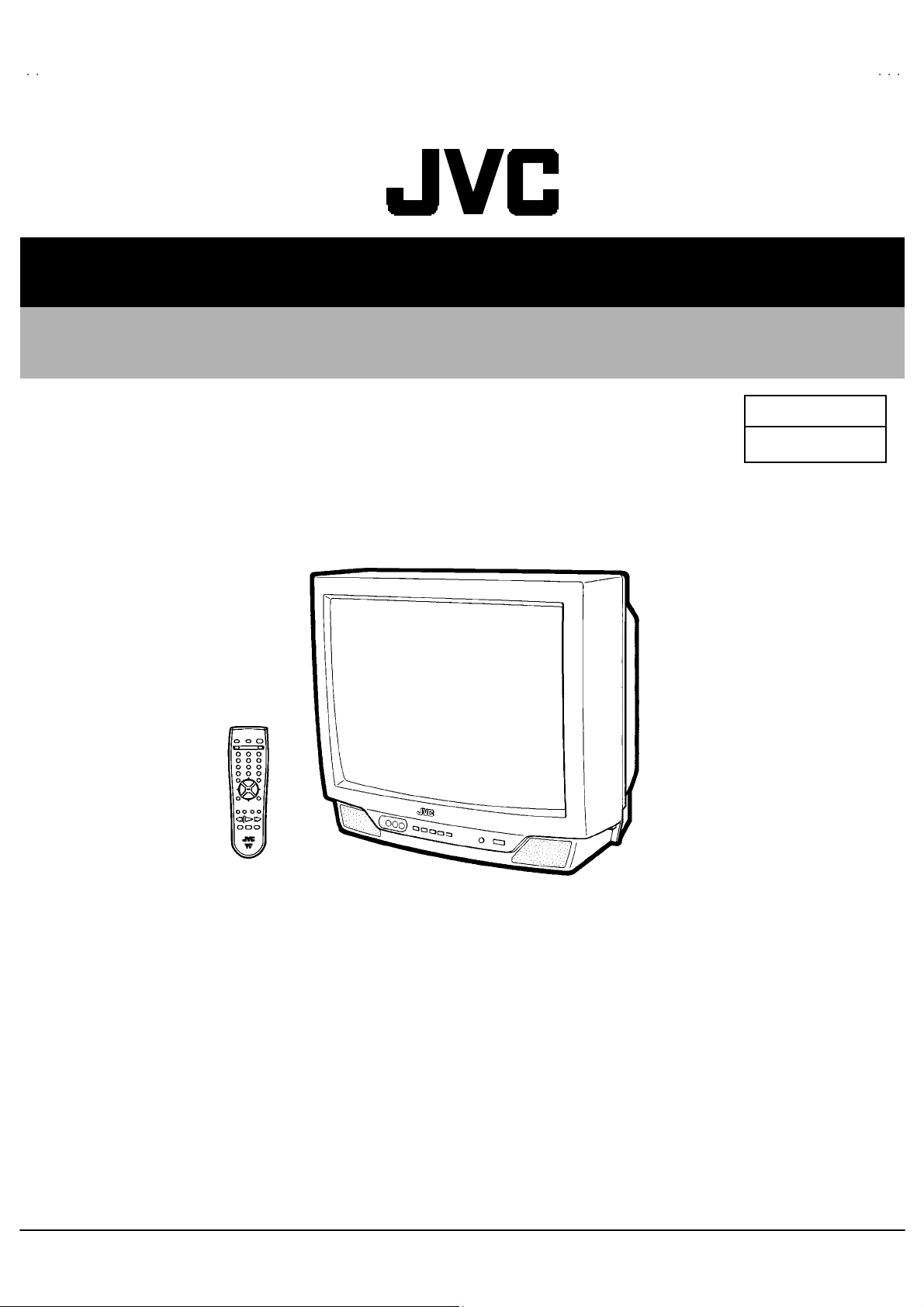
COLOR TELEVISION
AV-N29320
BAS IC CHAS SIS
AV-N29320
AV-N29320
/S
/R
FE
CONTENTS
!
SPECIFICATIONS ・・・・・・・・・・・・・・・・・・・・・・・・・・・・・・・・
! SAFETY PRECAUT IONS ・・・・・・・・・・・・・・・・・・・・・・・・・・・・・・・・
! FEATU RES・・・・・・・・・・・・・・・・・・・・・・・・・・・・・・・・
★
OPERATING INSTRUCTIONS (APPENDIX)
!
MAIN DIFFERENCE LIST ・・・・・・・・・・・・・・・・・・・・・・・・・・・・・・・・
! HOW TO IDENTIFY MODELS ・・・・・・・・・・・・・・・・・・・・・・・・・・・・・・・・
!
FUN CTIONS
!
SPECIFIC S ERVIC E INSTRUCTIONS
! SERVICE ADJUSTMENTS ・・・・・・・・・・・・・・・・・・・・・・・・・・・・・・・・
★ ST AND AR D CIRCUIT DIAGRAM (APPEN DIX) ・・・・・・・・・・・・・・・・・・・・・・・・・・・・・・・・
!
PARTS LIST
1
・・・・・・・・・・・・・・・・・・・・・・・・・・・・・・・・ ・・・・・・・・・・・・・・・・・・・・・・・・・・・・・・・・
・・・・・・・・・・・・・・・・・・・・・・・・・・・・・・・・・・・・・・・・・・・・・・・・・・・・・・・・・・・・・・・・
・・・・・・・・・・・・・・・・・・・・・・・・・・・・・・・・ ・・・・・・・・・・・・・・・・・・・・・・・・・・・・・
・・・・・・・・・・・・・・・・・・・・・・・・・・・・・・・・・・・・・・・・・・・・・・・・・・・・・・・・・・・・・・・・
・・・・・・・・・・・・・・・・・・・・・・・・・・・・・・・・・・・・・・・・・・・・・・・・・・・・・・・
・・・・・・・・・・・・・・・・・・・・・・・・・・・・・・・・・・・・・・・・・・・・・・・・・・・・・・・・・・・・・・・・
・・・・・・・・・・・・・・・・・・・・・・・・・・・・・・・・ ・・・
・・・・・・・・・・・・・・・・・・・・・・・・・・・・・・・・・・・・・・・・・・・・・・・・・・・・・・・・・・・・・・・・
・・・・・・・・・・・・・・・・・・・・・・・・・・・・・・・・
・・・・・・・・・・・・・・・・・・・・・・・・・・・・・・・・・・・・・・・・
・・・・・・・・・・・・・・・・・・・・・・・・・・・・・・・・・・・・・・・・・・・・・・・・・・・・・・・・・・・・・・・・
・・・・・・・・・・・・・・・・・・・・・・・・・・・・・・・・・・・・・・・・・・・・・・・・・・・・・・・
・・・・・・・・・・・・・・・・・・・・・・・・・・・・・・・・・・・・・・・・・・・・・・・・・・・・・・・・・・・・・・・・
・・・・・・・・・・・・・・・・・・・・・・・・・・・・・・・・ ・・・・・・・・・・・・・・・・・・・・
・・・・・・・・・・・・・・・・・・・・・・・・・・・・・・・・・・・・・・・・・・・・・・・・・・・・・・・・・・・・・・・・
・・・・・・・・・・・・・・・・・・・・・・・・・・・・・・・・
・・・・・・・・・・・・・・・・・・・・・・・・・・・・・・・・・・・・・・・・・・・・・・・・・・・・・・・・・・・・・・・・
・・・・・・・・・・・・・・・・・・・・・・・・・・・・・・・・・・・・・・・・・・・・・・・・・・・・・・・・・・・・・・・・
・・・・・・・・・・・・・・・・・・・・・・・・・・・・・・・・
・・・・・・・・・・・・・・・・・・・・・・・・・・・・・・・・・・・・・・・・・・・・・
・・・・・・・・・・・・・・・・・・・・・・・・・・・・・・・・・・・・・・・・・・・・・・・・・・・・・・・・・・・・・・・・
・・・・・・・・・・・・・・・・・・・・・・・・・・・・・・・・ ・・・・・・・・・・・・・・・・・・・・・
・・・・・・・・・・・・・・・・・・・・・・・・・・・・・・・・・・・・・・・・・・・・・・・・・・・・・・・・・・・・・・・・
・・・・・・・・・・・・・・・・・・・・・・・・・・・・・・・・ ・・・・・
・・・・・・・・・・・・・・・・・・・・・・・・・・・・・・・・・・・・・・・・・・・・・・・・・・・・・・・・・・・・・・・・
・・・・・・・・・・・・・・・・・・・・・・・・・・・・・・・・
・・・・・・・・・・・・・・・・・・・・・・・・・・・・・・・・・・・・・・・・・・・・・・・・・・・・・・・・・・・・・・・・
・・・・・・・・・・・・・・・・・・・・・・・・・・・・・・・・・・・・・・・・・・・・・・・・・・・・・・・・・・・・・・・・
COPYRIGHT © 2002 VICTOR COMPANY OF JAPAN, LTD.
・・・・・・・・・・・・・・・・・・・・・・・・・・・・・ 2
・・・・・・・・・・・・・・・・・・・・・・・・・・・・・・・・・・・・・・・・・・・・・・・・・・・・・・・・・・
・・・・・・・・・・・・・・・・・・・・・・・ 3
・・・・・・・・・・・・・・・・・・・・・・・・・・・・・・・・・・・・・・・・・・・・・・
・・・・・・・・
・・・・・・・・・・・・・・・・
・・・・・・・・・・・・・・・・・・・・・・・ 5
・・・・・・・・・・・・・・・・・・・・・・・・・・・・・・・・・・・・・・・・・・・・・・
・・・・・・・・・・・・・・・・・・・・ 5
・・・・・・・・・・・・・・・・・・・・・・・・・・・・・・・・・・・・・・・・
・・・・・・・・・・・・・・・・・・・・・・・・・・・・・・・・ ・・
・・・・・・・・・・・・・・・・・・・・・・・・・・・・・・・・・・・・・・・・・・・・・・・・・・・・・・・・・・・・・・・・
・・・・・・・・・・・・・ 8
・・・・・・・・・・・・・・・・・・・・・・・・・・
・・・・・・・・・・・・・・・・・・・・・ 12
・・・・・・・・・・・・・・・・・・・・・・・・・・・・・・・・・・・・・・・・・・
・・・・・・・・・・・・・・・・・・・・・・・・・・・・・・・・ ・・・・
・・・・・・・・・・・・・・・・・・・・・・・・・・・・・・・・・・・・・・・・・・・・・・・・・・・・・・・・・・・・・・・・
・・・ 4
・・・・・・
1-1
・・
・・・・
・・・・・2- 1
・・・・・・・・・・
31
6
No.520 09
May. 2002
May 2002
Page 2
A
V-N29320
(
)
)
)
SPECIFICATIONS
Items
AV-N29320/S AV-N29320/R
Dimensions (W×××× H×××× D) 65 4m m× 5 93mm×4 94mm
Mass 31 .1 kg
TV System and Color System
TV RF System
Color System
Sound System
TV Recei ving Channels and Frequency
VL B a nd
VH B and
UHF Band
CATV Receiving Channel s and Frequency
Low Band
High Band
Mid Band
Super Band
Hy p er Band
Ul tr a B and
Sub Mid Band
TV/CATV Total Channe l
Intermediate Frequency
Vide o IF Car rier
Sound IF Carrier
Color Sub Carrier
Power Input
Power Consumpti on
CCIR(M)
NTSC,
BTS C S ystem (Multi-Ch annel S ound )
(02~06) 54 MHz ~88MHz
(07~13) 17 4M H z~21 6M Hz
(14~69) 47 0M H z~80 6M Hz
(02~06, A-8) by (02~06 &01)
(07~13) by (07~13)
(A~1) b y ( 14~22)
(J~W) by (23~36)
(W +1~W+ 28) b y (3 7~ 64 )
(W +29 ~W + 84) b y (65 ~1 25)
(A8, A4~ A1) by (01, 96~99 )
18 1 Cha nn els
45 .75 MHz
41.25 MHz ( 4 .5MHz)
3.58MHz
12 0V AC , 60H z
11 3W
Contents
(54MHz~80 4MH z)
Picture Tube
Hi gh Vo l t ag e
Speake r
Audio Powe r Out put
Input terminal
Input 1 S-Video
Comp onent(V/Y , P
Input 2
Fr on t
Output ter minal
Variabl e Audio Output (R/L) More than 0~1550mVrms (+6dBs)
Antenna termina l 75Ω(VHF/UHF) Terminal, F-T ype Connector
Remote Control Unit RM-C 20 5 (AA /R6/U M- 3 b att ery× 2)
B, PR
Au dio (L , R )
Vide o(V
Au di o(L, R
29 ” (6 8cm) Mea sured Diag on al l y
28 .0 kV±1.3kV (at zero beam current)
5×12cm Oval type×2
1.2 W + 1.2 W
Y: 1Vp-p P ositive ( neg ative s ync p r ovided , wh en ter minat ed with 7 5Ω)
C: 0. 286V
)
1V p- p 7 5Ω(positive sync)
50 0m Vr ms ( -4 dBs ), High I mp ed ance ( RCA pin j ack)
1V p- p 7 5Ω(RCA pi n ja ck)
50 mV rm s (-4dB s), H i gh Imped an ce ( RCA pin j ack)
Low impedance (400Hz when modulated 100%) (RCA pin jack)
p-p
(bu rst si gnal, when t erm inate d with 75Ω)
De sign & speci f icatio ns ar e su bje ct to cha ng e wi thou t notice.
2
No.52009
Page 3

A
0
SAFETY PRECAUTIONS
V-N2932
1. The d es ign of t hi s p ro du ct c ont ains s pec ial h ardware, m an y
ci rcu its and c o mp on ent s s peci ally for saf ety purp oses. For
continued protection, no changes should be made to the
origina l des ign u nless a uth or i zed in wr iti ng by t he man uf actu re r.
Replacem en t par ts m ust be id ent ic al t o thos e u sed in th e
origina l circui t s. S er vic e sho ul d be perf or me d b y qu al i fied
p ers onnel o nly.
2. Alte r ation s of th e des i g n o r circu itr y of th e p r odu cts s hou l d n ot
b e m ad e. A ny de sign al te ra ti ons o r ad di tio ns will vo id th e
manufacturer's warranty and will furth er relieve t he
manu fac t urer of resp ons ibi lit y f or pe rs ona l in ju r y or p rope rt y
d am age r es u lt in g t heref rom .
3. M an y e lectrical an d mec h an ic al pa rt s in th e produ cts h ave
sp ecial s af ety-relat ed c haract eris tic s. Th ese char acter i sti cs ar e
oft en not e viden t from visu al inspe cti on nor can t he pr ote cti on
aff orde d by th em n ecess ar ily be obta in ed by usi ng
replac ement compon ent s rated for h ig her vo ltag e, wa ttag e, etc.
Replacem en t pa rt s wh ic h h ave t hes e sp ec ial s afet y
ch aracter istics a re i d entifi e d in th e par ts l ist of S ervi c e m an ual.
Electrical components ha ving such fe atur es are identified
by shading on the schematics and by (!!!!) on the parts list
in S erv ice manual. Th e us e of a su bst itu te re pl ac emen t whi ch
does not have the same saf et y characterist ics as the
reco mmen ded replac emen t pa rt sho wn i n the pa rts li s t of
Se rvi c e ma nu al m ay c ause sh ock, f ire, or o ther hazards.
4. Use iso lat io n tr an sf orme r when hot chass is .
The chassis and any sub-chassis contained in s ome products
are c onnect ed to on e side of th e AC p ow er l i ne . An i sola ti on
tr ansf or m er of ad equ ate cap acity s h ou ld be inser t ed bet ween
th e p rodu ct and t he AC p ow er s u pp ly p oi nt whil e p erfor m ing
an y ser vice on so me pr oducts when th e H OT ch assis is
exp ose d.
5. Don't short between the LIVE side ground and I SOLATED
(NEUTRAL) side ground or EARTH side ground when
repairing.
So m e mod el 's p ower c ircuit is par t ly di f fer en t in the GN D. T h e
diff er enc e of t he GND i s sh own by th e LI VE : (") side GND,
th e ISO LAT ED(NEU TRAL) : (#) sid e GND and EAR TH : ( $)
si de GND. Don 't sho rt be tw ee n t he LIVE sid e GN D a nd
ISO LATE D(N EUTR AL) si de GN D or EART H si de GND and
never measure with a measuring apparatus (oscilloscope etc.)
th e LI VE s ide GND a nd ISO LATED ( N EUTRA L) si d e G ND or
EARTH sid e GND at the s ame time.
If above note will not be kept, a fuse or any parts will be broken.
6. If any re pa ir h as b ee n mad e to th e ch assi s, i t i s re commend ed
th at t he B1 se tti n g s h ou ld b e chec k ed or ad juste d (S ee
ADJUSTM ENT OF B 1 POW E R SUPPL Y).
7. The hig h volt age a pplied t o the pictu re tu be mu s t c o nform with
that specified in Service manual. Excessive high voltage can
cau se an incr ease i n X-R a y emis sion , arcin g and p ossi bl e
com po nent d am ag e, th eref or e op er ation un der exces s ive hi gh
vol ta ge c ond it i ons sh ould be ke pt to a m in i mu m, or sh ou l d be
preve nt ed. I f seve re arc in g occu rs, r em ove th e AC p ower
immediately and determine the cause by visual inspection
(incor r ec t i nsta lla ti on , cr ac ked o r melte d hi gh vol tag e harness ,
p oor s olde ring, etc . ). T o mainta in the prop er minimum level of
soft X-Ray emission, components in the high voltage circuitry
incl ud i ng the pi ctu r e tu be mu s t be the ex a c t r ep lac em en ts or
alte rn at ives a ppr o v ed b y th e ma nuf actu r er of the co mplete
prod uct.
8. Do n ot c hec k high vol ta ge by dr awing a n ar c. U s e a hi gh
vol ta ge m ete r or a hi gh volt age pro be w i th a VTVM. Dis char ge
th e p ictu r e tu be bef ore a tte mp ti ng meter co nne ction , b y
con nec ting a cl i p lead to th e gr ou nd fram e a nd con n ecti ng the
oth er e nd of t he lead th roug h a 10 kΩ 2W resist or to t he ano de
bu tto n.
9. W hen s e rvice is r equ i r ed, ob serve th e o rig in al l ea d dress.
Extra p r ecau ti on sh ou ld be giv en to assu r e correct lea d dr es s
in the hi gh volta ge c ircu it area . W her e a sh ort cir cuit ha s
occu rr e d, th ose c ompon en ts that i nd ic ate ev iden ce of
overheating should be replaced. Always use the
manu fac t urer 's r epl acem ent com p on ents.
10 . Isolation Check
(Safety for Electrical Shock Hazard)
Af ter re-a ssem bl i ng th e prod uct , alw ay s pe rf or m an iso lati on
ch eck on th e expo sed m eta l p ar ts of th e c abi n et ( ant en na
ter m i na ls, vi de o/a ud i o in pu t and out put ter mi n al s , C on trol
knobs, metal cabinet, screwheads, earphone jack, control
sh afts, etc.) to be s ur e th e pr o duc t is saf e t o op er at e with out
d ang er of elect rica l shoc k.
(1) Dielectric Strength Test
The is olat io n b etwe en the AC primary c ircu it and all meta l parts
exp osed t o the us er, par t icu lar l y an y expo sed metal p ar t h aving
a re tur n pat h to the ch assis sh ou ld w i ths t and a volta ge of
11 00V AC (r .m .s.) for a per i od of on e sec ond.
(. . . . Withstand a volta ge of 1100 V A C (r.m.s.) to an appliance
rate d up to 1 20V , and 3 000V AC ( r .m. s.) t o an appl i anc e ra ted
200V or more, for a period of one second.)
Thi s m eth od of test r equ ires a t est eq uip me nt n ot g enerally
fou nd in t he servi c e t ra de.
(2) Leakage Current Check
Plug t he A C line c or d di r ect ly int o th e AC ou tl et (do not u se a
line is olati on tra nsf orm er dur i ng this che ck.). Usi ng a " L eakage
Current Test er", m ea sure t he lea kag e c ur r en t fr om each
exp ose d m eta l par t of th e c a bi ne t, p ar tic ul ar l y an y expo s ed
metal part having a retu r n path to t he ch assis , to a known good
ea rt h gr o und ( water p i pe, etc.) . A ny l ea kag e c ur r en t must not
exce ed 0.5m A AC ( r .m. s.) .
Howev e r, in t ro pical a rea, thi s m ust no t e xc eed 0.2m A AC
(r.m.s.).
"""" Alte rn at e Che ck M ethod
Plug t he A C line c or d di r ect ly int o th e AC ou tl et (do not u se a
line isolation transformer during this check.). Use an AC
vol tm et er h aving 100 0 o hms per v olt or m or e sen siti vit y in the
follo wing ma nne r. C on nec t a 1 50 0Ω 1 0W resi s tor pa ralle l ed
by a 0.15μ F AC-typ e cap acitor b etwe en an exp ose d meta l
p art and a k no wn go od ear th gr ou nd ( w ate r pip e, et c.).
Measu re th e A C vo ltag e acr os s th e r esist or wit h t he AC
voltmeter. Move the res istor connection to each exposed metal
part, particularly any exposed metal part having a return path to
th e ch assis , an d m ea sur e t he A C volta ge acr oss the r esis to r.
Now, reve rs e th e plu g in t he A C out l et a nd rep e at e ach
measu rem ent. An y volta ge measu re d mus t not exce ed 0.7 5V
AC (r.m. s.) . This corresponds t o 0 .5 mA AC (r.m. s.).
Howev e r, i n trop ic al ar ea, thi s must n ot excee d 0 .3V AC
(r.m.s.). This corr esp onds t o 0 .2mA A C (r.m .s.).
AC VOLTMETER
(HAVING 1000 Ω/V,
GOOD
EARTH
GR OUND
11 . High voltage hold down circuit check.
Af ter rep ai r of th e high vol t age h ol d d own c ir cui t, th is c i rcu it
sh all be c hec ked to op er ate correctly.
See item "Ho w to check the high voltage hold down
cir cuit".
This mark shows a fas t
operating fuse, the
letters indi cated below
show the rating.
0.15μF AC-T YPE
1500Ω 10W
OR MOR E SENSIT IVITY)
PLACE THIS PROBE
ON E A C H EX PO SE D
ME T AL PA RT
A V
No. 52009
3
Page 4

A
V-N29320
FEATURES
New chas sis design en abl es use of a si ngl e boar d with simp lif ied
"
circuit ry.
User s can m ak e fun t o c onnect th e Digi tal Video Disk pl ayer wit h
"
the comp onent vi deo signal i npu t termi nal .
Provid ed w ith miniatu re tuner (TV/CATV ).
"
Multif unct ion al rem ote con tro l p ermits pic tu re a dj ustm ent.
"
Ad opti on of t he CHANNEL GU ARD fu nction pr events th e speci fi c
"
chan nels from being selected, unl ess th e “ID numbe r” is k ey in.
2
"
I
C bus control utilizes single chip ICs.
"
Adoption of the VIDEO STATUS f unction .
"
Adoption of the ON/OFF TIM ER fun cti on.
With 75ΩV/U in c ommon ( F-Type) ANT Ter m in al.
"
SLEEP TIMER for s etting in re al t ime.
"
Clos ed- capti on b roa dcasts can be view ed.
"
"
Bu ilt - in MT S sys tem.
"
Built-in H YPER-SURROUND system.
"
S-VIDEO in put termi nal for tak i ng bes t advantag e of S uper VH S .
Variable Au di o outp ut te rminal.
"
3 L IN E D i gi tal Comb f ilter Im pr oved pictu re q ual ity.
"
4
No.52009
Page 5
A
MAIN DIFFERENCE LIST
V-N29320
!!!!
Parts Name
MAIN PW B SFE-10 10A -M 2 SF E- 1011A -M 2
!!!!
ITC TU BE A6 8QD N 891 X001 A6 8AD T 25 X881
Model name
AV-N29320/S AV-N29320/R
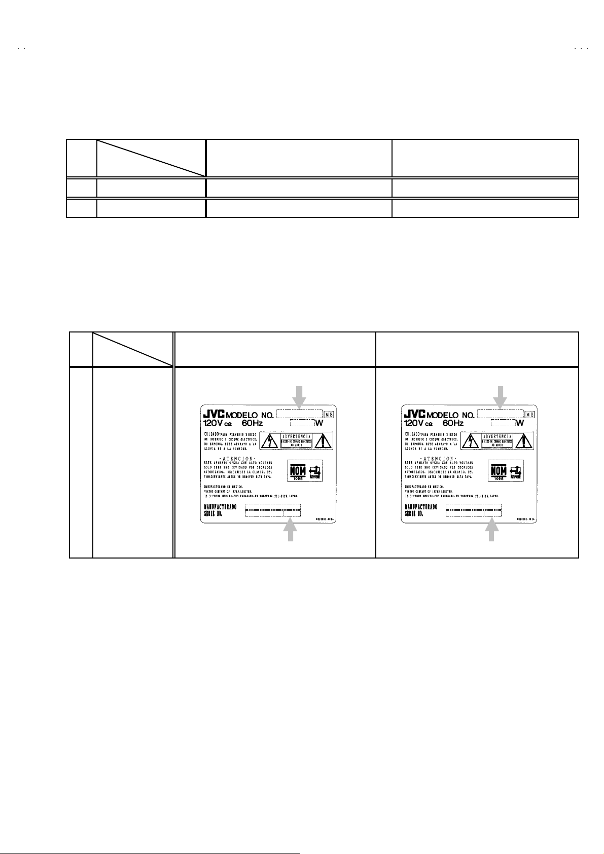
HOW TO IDENTIFY MODELS
The differenc e between AV -N29 320 /S and AV -N29 320 /R is i n th e PICT U RE TUBE.
As t he res ul t of the diffe ren ce in pictu re t ube, the MAIN PW B al so dif fer s.
!
Model
Parts na me
AV-N29320/S AV-N29320/R
Ind ic ated A V- N2 932 0
Ind ic ated A V- N2 932 0
!
RAT ING L ABEL
Indic ated “S”
Indic ated “R”
No.52009
5
Page 6
A
V-N29320
FUNCTIONS
■■■■
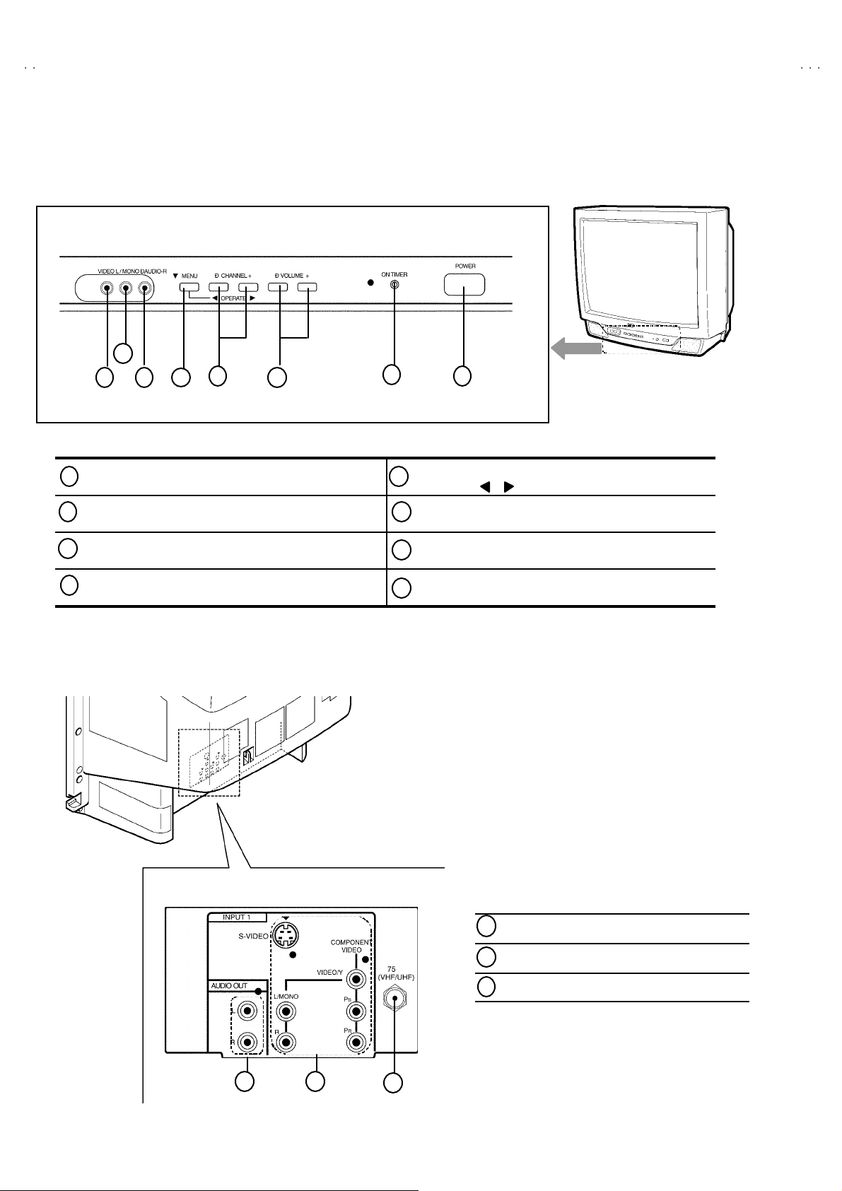
FRONT PANEL CONTROL
2
1
3 6
5 8
4
7
1
INPUT2 VIDEO terminal
2
I NPUT2 AUDIO L MONO terminal VOLU ME -/+ buttons
3
INPUT2 AUDIO R terminal ON TIMER LED
4
MENU but ton POW ER button
■■■■
REAR TERMINAL
CHANNEL -/+ buttons
5
OPERATE / buttons
6
7
8
1
AUD I O O UTPUT (L, R) t erm inals
INPUT1 (S, V/Y, PR, PB, L, R) terminals
2
VHF / UHF terminal
3
1
6
2
3
No.52009
Page 7
A
■
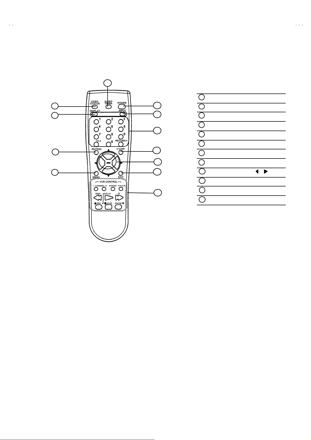
REMOTE CONTROL UNIT [RM-C205]
11
1
2
3
4
V-N29320
1
VI DEO STATUS key
5
6
7
8
9
10
12
DISPLAY k ey
2
MUTING key
3
MENU key
4
5
POWER key
INPUT key
6
CHANNEL keys
7
V-CHIP key
8
FU NCTI ON ( ▼/ ▲, / ) Key s
9
EXIT key
10
SLEEP TIMER k ey
11
VCR CONTROL keys
12
No.52009
7
Page 8

A
V-N29320
SPECIFIC SERVICE INSTRUCTIONS
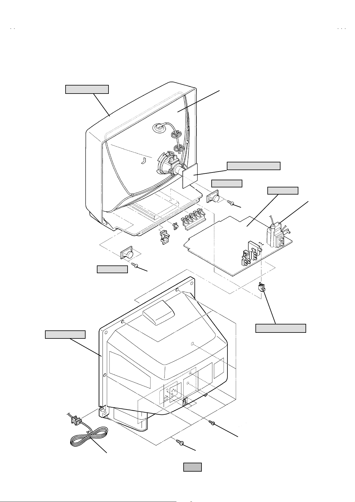
DISASSEMBLY PROCEDURE
REMOVING THE REAR COVER
1. Disc onnec t t he po w er pl u g f rom wa ll out le t.
2. As s hown i n th e Fig .1, r em o ve th e 7 screws marked
3. As s hown i n Fig.1 , re mo ve t he 3 screws marked
4. Then remo ve th e REAR COVER toward you.
""""
!!!!
.
.
CHECKIN G THE PW BOARD
To check the PW Boar d from back side.
1. Pull out the ch assis ( refer t o REMOVI NG TH E MAIN PWB ).
2. Erect th e chas sis ver tic a lly s o th at you c an ea sily ch eck th e bac k
si de of the PW Boar d.
REMOVING THE MAIN PWB
" After r emovi ng the REAR C OV ER.
1. Pic k th is s i de of th e MA IN PWB an d r aise on e slig htl y, tak e off the
PW B stopp er mar ked
2. W i thdr a w t he chass is backw a rd .
(If n ecess ary , r emove t he wire clam p, c onn ec t ors etc.)
####
f rom th e c abin et b ott om .
REMOVING THE SPEAKER
"
After removing the rear cover.
1. As shown in Fig. 1, removing the screws marked
remove the speaker.
2. Foll ow th e s ame st eps when r em oving th e oth er ha nd sp eak er.
NOTE : When removing the screws marked
remove th e lower si de s crew first, an d th en r em ove t he
up per one .
$$$$
of th e sp eak er ,
$$$$
then
,
CAUTION
"
When e recti ng th e ch assi s, b e c ar ef ul s o tha t th er e w ill b e no
contacting with other PW Board.
"
Befor e tu rni ng o n power, m ake s ure th at t he w i r e con nec tor i s
prop er l y con nected .
"
When conducting a che ck with power supplied, be sure to
confirm that the CRT EART H WIRE (BRAIDED ASS’’’’ Y) is
connec ted to the CRT SOCKET PW boar d.
WIRE CLAMPIN G AND CABLE T YING
1. Be sure t o cl a mp th e wire.
2. Never rem o ve th e c able ti e use d f or tying th e wi res togethe r.
Should it be inadverte ntly removed, be sure to tie the w ires with a
new cable tie.
8
No.52009
Page 9
A
V-N2932
0
FRONT CABINET
CRT
CRT SOCKET PWB
SP EAKER
MAIN PWB
HV T
$$$$
REAR COVER
SP EAKER
$$$$
####
PWB STOP PER
""""
POWER CORD
!!!!
Fig .1
No.52009
9
Page 10

A
V-N29320
C BUS
S)
)
SYS0
MEMORY IC REPLACEMENT
1. Memory IC
This TV uses memory IC.
Thi s m em or y IC st ores d at a f or pr op er o per a tion of the video a nd defl ection ci r cuits.
When r ep la cing t he mem or y IC, be sure to use an IC co ntai ni ng this (initia l value ) dat a.
2. Memory IC replacement procedure
(1) Power off
Switch off th e pow er an d di scon nec t th e p ow er c o rd fro m t he outlet.
(2) Replace the memory IC
Be sure t o use a memory I C writte n with th e initia l s ettin g data.
(3) Power on
Con nect th e power cord to th e o utlet a nd s witch on th e power.
(4)Confirm t he sy st em con st an t v alue
"
12 .S YSTEM (SYS ) do not a dj ust norm ally.
"
The adjustment should not be done without signal.
! Ho w t o ent er t he SY STEM (SYS ).
1) Pr ess the SL EEP TIMER ke y and se t SL EEP TIM ER f or 「0 min」.
2) Be for e disap pear the dis pl a y of S LEEP TIM ER set ti ngs , simu ltan eo usly
press the DISP LAY key an d VIDEO STA TUS ke y of the remot e c ont rol
un it.
3) The SERV ICE M EN U s cr een of Fig.1 is d isp layed.
4) While the S ERVICE MENU is displayed, select t he 12.SYSTEM(SYS)
item with FUNCTION ▼/▲ keys, and the FUNCTION / keys is
pressed, the screen will be displayed as shown in Fig.2.
5) R efe r to the SY STEM ( SY STEM C ON STA NT) TAB LE 1 a nd check t he
setting items. If the value is different, select the setting item with the
FUNCTION ▼/▲ keys and ad just t he sett ing wi th th e FU NCTION
/ keys . (The let ter s of th e s el ec te d i t em are displ a yed in yellow.)
6) W hen adjustment has co mp lete d, t he v al ues sto re in to memory IC
automat ically
7) Press the EX IT key t wice to r eturn th e norm al screen.
SETTING N o
SE RVICE MEN U
SERVICE MEN U
1.V/C(S) 2.DEF(D)
3. SOUND(A) 4 .OTHERS( F)
5.PIP(PIP) 6.3L Y/C(LYC)
7.LOW LIGHT 8.HIGH LIGHT
9.RF AFC 10.VCO
12.SYSTEM(SY
11.I2
SELECT BY
OPERATE BY EXIT BY
Fig.1
12 .SY STEM(SY S
SETTING ITEM
1 VI DEO IN
Fig.2
Verif ied
EXIT
***
SETTING VAL UE
KEY ASSIGNMENT OF REMOTE CONTROL UNIT
(5) Rec eive channel setting
Refe r to the OPERA TING IN S TRUCTIO NS (USER'S GU IDE) and set
th e r ec e i ve ch annel s ( Cha nn els Pr eset) as des crib ed.
VIDEO
STA TUS
SLEEP
TIMER
DISP LAY
(6) User settin gs
Check th e us er s ett ing it em s acc ording to TABL E 2 .
Where thes e d o not agree, r ef er to th e OP ERATIN G I NSTRU CTION S
(USER'S GU IDE) an d s et t he it ems as de scrib ed.
FUNCTION
FUNCTION
▼/▲
/
(7) SERVICE MENU setting
Ve rif y what to s et i n th e SER VI CE MENU, a nd s et wh at ever is
necessary. (Fig. 1) Ref er to the SERVICE A DJUSTM ENT f or setting.
10
No. 52009
EXI T
Page 11

A
0
TABLE 1 (System Constant setting)
No Setting item Variabl e range
SY S01 VIDEO IN 0~4 2
SY S02 PIP 0~1 0
SY S03 3D Y/ C 0~1 0
SY S04 Y CV 0~1 0 SY S16 EZ SU RF 0~1 0
SY S05 CCD PCH K 0~1 1 SY S17 ID DISP 0~1 0
SY S06 PUR ITY 0~1 0 SY S18 COMPU LIN K 0~1 0
SY S07 VM 0 ~1 0 SY S19 C CD 0~1 1
SY S08 NOISE CR 0~1 0
SY S09 CLR TEMP 0~1 0
SY S10 TH EATE R 0~1 0
SY S11 TH EATE R PRO 0~1 0
SY S12 BB E 0~1 0 SY S24 CXA1 875 0~1 0
Initial setting
value
No Settin g item Variabl e ra nge
SYS 13 HYP SURR
SY S14 16:9 MD
SY S15 HYP S CA N
SY S20 VCH IP
SY S21 VCH IP C A
SY S22 JVC L OGO
SY S23 CMP IN
0~1
0~1
0~1
0~1
0~1
0~1
0~1
TABLE 2 (User setting)
Setting item Setting value Setting item Setting value
Use remo t e co ntrol ler ke ys
V-N2932
Initial setting
value
0
0
1
1
1
1
0
POWE R OFF DISPLA Y OFF
CHA NNEL CH-02 VIDEO STATUS DYNAMIC
VOL UME 10 HYPE R S URROUND OFF
TV/V IDEO TV
Settings of ME NU
PICTURE MENU INITIAL SETUP MENU
TINT CENTER
COLO R CENTER FRONT PANELLOCK OFF
PICTURE CENTER+8 V2 COMPONENT-I N NO
BRIGHT CENTER AUTO SHUT O FF OFF
DETAIL CENTER+10
COLO R TEMPERATURE HIGH
NOISE MUTING ON CHANNE L SU MM AR Y U nn ecess ary to set
SOUND ADJUST MENU
BASS CEN TER
TR EBL E CEN TER XD S I D
BALANCE CENTER
LA NG U AGE
CLOS ED CAPTIO N OFF
AUTO TUNER SET UP AIR
V-CHI P OFF
SE T LOC K C ODE ( 000 0) Unn eces sary to set
ENG
ON
MTS ST E RE O
CLOCK / TIMERS MENU
SE T CLOC K
ON / O FF TIMER OFF
MA NUA L
TIME ZONE : PACIFIC
D.S.T. : OFF
No. 52009
11
Page 12

A
V-N29320
SERVICE ADJUSTMENTS
ADJUSTMENT PREPARATION
1. You c an ma ke the nec es sary adjustme nts for t his unit wi th
eit her t h e R emo t e Co ntrol Unit o r With th e adjustme nt
tools and parts as given below.
2. Ad justment with t he Remote Control Unit is ma de on t he
bas is of t h e initial sett in g v al ues, howev er, t he ne w s etti ng
values which set the screen to its optimum condition may
differ f rom the init ia l s ett ings.
3. Make sure t hat AC p ower i s tu r ned on c orrec tly.
4. T ur n on t he pow e r f or set an d test e qu i pm ent bef ore us e, an d
start th e adjus tme nt p r oced ur es aft er wai ti n g at least 3 0
min ute s.
5. Unless oth erw is e spec if ied, prep ar e the m ost s uitab l e r ece pti o n
or inp ut sign al for adjust ment.
6. Never t ouc h an y adjustmen t p arts which a re n ot sp ecified i n th e
list for this adjustment - variable resistors, transformers,
condensers, etc.
7. Pr es etti n g b efore a djust ment.
Unl es s oth er w is e spec if i ed in th e ad jus tm en t instruct ions,
pres et t he f ollowing function s w i th the rem ote co ntr ol u nit:
User menu preset value
MENU ITEM PRES ET V ALUE
PICTURE MODE (VSM) DYNAMIC 0
BA SS, TREB LE, BA LANCE
TINT, COLOR,
PICTURE, BRIGHT , DETAIL
MTS
CENTER
CENTER
STEREO
ADJUSTMENT EQUIPMENT
1. DC voltmeter (or digital voltmeter)
2. Oscilloscop e
3. Sign al g en erat or (P att er n g ener at or)[NTSC
4. Remote control unit
5. TV a ud i o m ul ti pl e x sign al ge ne rator .
6. Frequ enc y cou nte r
]
ADJUSTMENT ITEMS
Ad just ment it em s Adju st men t it ems
B1 POW ER SU PPL Y SUB B RI GH T
MAIN VCO SUB CONTRAST
RF. AGC SUB COLOR
FOC US SUB TI NT
V. HEIGH T V. CENT ER MTS IN PUT L EVEL check
H. CENTER
WHITE BA LANCE ( Low L igh t)
MTS SEP ARATIO N
KEY ASSIGNMENT OF REMOTE CONTROL UNIT
VIDEO
STA TUS
DISP LAY
FUNCTION
/
SLEEP
TIMER
FUNCTION
▼/▲
EXI T
WHITE BA LANCE ( Hig h L ight )
12
No.52009
Page 13

A
0
ADJUSTMENT LOCATIONS
(
)
V-N2932
FRONT
POWER
MAIN PWB
POWER
CRT SOCKET PWB
Within MAIN PWB ASS'Y
TP-B
T
TP-E
(SOLDER SIDE)
VOL+ VOL- CH+ CH- MENU
E1
TOP
CR T EAR TH
(BRAIDED ASS' Y)
S
IC70 2
F901
IC20 1
T111
HV
IC42 1
IC10 1
S401
TUNER
HV T
IC90 1
U
B1
X
UPPE R : FOCU S
AV IN / OUT
No.52009
LOWER : SCREEN
13
Page 14

A
V-N29320
BASIC OPERATION OF SERVICE MENU
1. TOOL OF SERVICE MENU OPE RATION
Operat e the SERVICE MEN U with th e REM OTE CO NT ROL UNIT.
2. In gene ral, basic setting (adjustments) items or verifications are perfor med in the SERVICE MENU.
(1) V/C (S) ・・・・・・・ ・・・・・・・・・・・・・ ・ This se t th e s ettin g valu es ( a djustm e nt values) of th e VIDEO/CHRO MA circu its.
(2) DEF (D)
(3) SOUND (A) ・・・・・・・・・・・・・・・・・ This se t th e s etting valu es (adjustment values) of the AUD IO circuit.
(4) OTHERS (F)
(5) PIP (PIP) ・・・・・・・・・・・・・・・・・・・ This se t the s ettin g valu es( adjustm ent va lues) of th e P ICTURE-IN- PICT UR E circ uit.
(6) 3L Y/C (LYC) ・・・・・・・ ・・・・・・・・・ This i s us ed when the 3 L Y/C MODE is verified . [Do not adjust]
(7) LOW LIGHT
(8) HIGH LIGHT ・・・・・・・・・・・・・・・・ Thi s se ts th e setti ng values ( adj ust me nt val ues) of t he W HITE BALAN CE cir cuit
(9) RF AFC ・・・・・・・・・・・・・・・・・・・・ This is used when the RF AFC MODE is verified. [Do not adjust]
(10) VCO ・・・・・・・・・・・・・・・・・・・・ ・・・ This i s us ed w hen the I F VC O is adj us ted .
(11) I2C BU S ・・・・・・・・・・・・・・・・・・・・ This i s us ed w hen ON/O FF of t he I2C BUS CTRL is set. [Fixed ON]
(12) SY STEM ( SYS) ・・・・・・・ ・・・・・・・ This i s us ed w hen the S YST E M is ve rif ied. [Do not adjust]
3. Basi c Op era tio ns of the SERVI CE M ENU
(1) Ho w to enter the SERVICE MENU.
(2) SERVICE MENU screen selection
・・・・・・・ ・・・・・・・・・・・・・
・・・・・・・ ・・・・・・・・・
・・・・・・・ ・・・・・・・・・・
Press the SLEEP TIM ER key and set the SLE EP TIM ER for
「0 MIN」 .
Then press the DISPLA Y key and VIDEO STA TUS key of
the remote contr ol u nit at the same time to ent er th e
SERVICE MENU screen.
In SERVICE MENU, press th e FUNCTION ▼/▲ key to
sel ect an y of th e SU B MEN U it em s.
(The l e tte rs of the s elect ed it em s are disp layed in ye llo w. )
This se t th e s etting valu es (adjustment values) of th e DEFLECTIO N circuit.
Thi s is us ed w hen the O THERS MO D E i s ver i fi ed . [Do not adjust]
(PIP i s me ans as P icture I n P ictur e) [Do not have Function]
Thi s se ts th e s ettin g va l ues (a djust ment val u es ) of the WHITE BA LANCE cir cuit.
SERVIC E MENU
1.V/C(S) 2.DEF(D)
3.SOUND(A) 4.OTHERS(F)
5.PIP(PIP) 6.3L Y/C(LYC)
7.LOW LIGHT 8.HIGH LIGHT
9.RF AFC 10.VCO
11.I2C BUS 12.SYSTEM(SYS)
SELECT BY
OPERATE BY EXIT BY
EXIT
(3) Enter the any setting ( adjustment ) mode
"
1.V/C (S), 2.DEF (D), 3.SOUND (A), 4.OTHERS (F),
5. PIP ( PI P), 6. 3L Y/ C (LY C), 7. LO W L IG HT, 8 .HI GH
LIGHT, 9.RF AFC 10.VCO 1 1.I2C BUS an d 12.SYSTEM
(SYS) mode
1) If s elect an y of 1.V/ C (S) / 2.DEF (D) / 3.SOUND (A)
/ 4.OT HERS (F) / 5.PIP ( PIP ) / 6.3L Y/C ( LYC) /
7.LOW LIG HT / 8.HIGH LIGHT / 9.RF AFC /
10 .VC O / 11.I2C BUS /12.SY STEM (SYS) it ems ,
an d t he FU NCTION / key is pr es s ed fr om
SERVICE MENU ( MAIN MENU ), the each scree ns
will b e dis played as shown in figure page later.
2) The n the sett in gs or verification s ca n be p erfor m ed
KEY ASSIGNMENT OF REMOTE CONTROL UNIT
VIDEO
STA TUS
DISP LAY
FUNCTION
/
SLEEP
TIMER
FUNCTION
▼/▲
EXI T
14
No. 52009
Page 15

A
0
SERV ICE M ENU (MAIN MENU)
SE RV IC E M EN U
1.V/C (S) 2.DE F(D)
3.SOUND(A) 4. OTH ER S(F)
5.PIP (P IP) 6. 3L Y/C( LYC)
7.LOW LIGHT 8 .HIGH LIG HT
9.RF AFC 10 .VCO
11.12 C BUS 12.SYST EM(SYS)
SELECT BY
OPE RAT E BY EXIT BY
EXIT
V-N2932
1.V/C ( S)
R F 4 : 3 S T D L O W
S0 1 BR IG H T
2.DEF (D)
R F 4 : 3 S T D L O W
D 01 V F REQ
3.SOU ND(A)
A 01 IN L EVE L
***
***
***
7.LOW LIGH T
BRIGHT
***
***
***
8.HIGH LIG HT
***
9.RF AFC
TOO HIGH GOOD T OO LOW
T U NE R M AI N
AF G O N
FIN E
DO not ad ju st
**
4.OTHERS( F)
F0 1 OS D POSI
5.PIP(PIP)
PI P01 B RIG HT
6.3L Y/C(LY C)
LYC01 MODE
***
***
***
10.VCO
T U NE R MA IN
HI GH LE V EL
RE FERENCE LEVEL
LO W LEVEL
SY N C NO
11.I2C BUS
I2 C BU S ON
12.SY ST EM ( SY S)
SY S01 VIDE O IN
DO not ad ju st
***
No. 52009
15
Page 16

A
V-N29320
G
(4) Setting method
1) FUNCTION ▼/▲ key.
Select t he SETTIN G IT EM .
2) FUNCTION / key
Setti ng (adjust) the SETTIN G VA LUE of t he SETTIN G ITEM.
When the key is r el ea sed th e SET TI NG VAL UE w ill b e st ored
(memorized).
3) EX IT key
Retu rn s to the p revious scr een .
(5) Rel easing SERVICE MENU
1) Af ter retu rn i ng to t he SE RV ICE MENU up on c o mp l eti on of th e s etti n g
(adjus tment) wo rk, pr ess t he EXI T key ag ain.
★ The s etting s f or L OW LIGH T and HI GH L IGH T are des cribe d i n th e
WHITE BA LANCE p age of AD JU STMENT .
★ The s ettin g for MA IN VCO ar e d escribed in th e VC O p age of
ADJUSTM ENT.
SETTING N o
RF 4 : 3 STD LOW
SETTING
ITEM
1.V/C (S)
BRI GHT
***
***
***
7.LOW LIGHT
***S01 B RIG HT
SETTING VAL UE
***
8.HIGH LIGHT
TUNER MAIN
HI
H LEVEL
REF ERE NCE L EVEL
LOW LEVEL
SYNC NO
10.VCO
16
No. 52009
Page 17

A
V-N2932
0
INITIAL SETTING VALUE OF SERVICE MENU
1. Adjustment of the SERVICE MENU is made on the basis of the ini tial setti ng va lu es ; ho wev er, the new setting values whic h
set the scree n in its optimum condition may differ from the initial setting.
2. Do no t change the initial Setting Values of the Setting (Adjustment) items not listed In “ADJUSTMENT”.
"
V / C M O DE
Initial setting value
RF EXTERNAL (S,CV ) COMPONENTNo. Setting item
STANDARD THEATER STANDARD THEATER STANDARD THEATER
S01 BRIGHT
S02 PICTURE
S03 COLOR
S04 TIN T
S05 DET AIL
S06 BRIGHT +-
S07 PICT+ -
S08 COLOR +-
S09 TIN T+-
S10 DETAIL +-
No. Setting item
S11 R CUT OFF 50 --- --- --- --- --- --- ---
S12 G CUT OFF 50 --- --- --- --- --- --- ---
S13 B CUT OFF 50 --- --- --- --- --- --- ---
S14 R DRIVE 64 --- --- --- --- --- --- ---
S15 B DRIVE 64 --- --- --- --- --- ---
S16 R CUT+-
S17 G CUT+- --- 0 0 0 0 --- --- ---
S18 B CUT+- --- 0 0 0 -10 --- --- ---
S19 R DRV+- --- +5 +7 +7 0 --- --- ---
S20 B DRV+- ---+6-9-9 0 ---------
S21 NT SC MAT 33112211
S22 BLACK S T 2 - -- 1 - -- - -- - -- - -- - --
S23 DCREST 1 - -- 1 - -- - -- - -- - -- - --
S24 DCRSW 1 - -- 1 - -- - -- - -- - -- - --
64 --- --- --- --- ---
65 --- --- --- --- ---
45 --- --- --- 47 ---
60 --- --- --- 64 ---
30 - -- 35 --- 40 ---
--- 0 0 --- +3 ---
- -- - 15 0 --- 0 - --
----3-2---------
--- -6+2------ ---
--- +3 --- --- --- ---
Initial setting value
RF/EXT (S,CV)
STANDARD THEATER STANDARD
LOW HIGH LOW HI GH LOW HIGH LOW HI GH
--- 0 0 0 -10 --- --- ---
COMPONENT
--- c a n n ot be ad ju stm ent
THEATER
No. Setting item
S25 AS Y SHRP 444
S26 BP F FO 00---
S27 KIL R OFF 00---
S28 KIL R SEN 11---
RF EXTERNAL (S,CV ) COMPONENT
No. 52009
Initial setting value
17
Page 18

A
V-N29320
No. Setting item Initial setting value No. Setting it e m Initial setting v alue
S29 RGB MU TE 0 S3 9 Y MUTE 0
S30 BLUE B 0 S40 SVM G AIN 0
S31 VIDEO SW 3 S4 1 SV M PH 0
S32 CMP ABCL 0
S33 RGB ABCL 0 S43
S34 OSD CON T 9 S44 V1 GAI N 4
S35 SUB CONT 8 S45 AGC ADJ 80
S36 AB L GA IN 0 S46 VMOFF DE 0
S37 ABL PNT 3 S4 7 AP C CL K 1
S38 Y G AM MA 1
S42 WPL
COL G MM
0
0
"
DE F M O D E
Initial setting value Initial setting value
No. Setting item
D01 V FREQ 0303D18
D02 AFC GAI N 0202D19 EWCR TOP 16 16 16 16
D03 H POSI 12 12 12 12 D20
D04 H POSI+- --- --- --- --- D21 EWCR BTM 16 16 16 16
D05
V PHASE
D06 V PH+- --- --- --- --- D23 EW PARA 26 26 26 26
D07
V S IZE
D08 V SIZE +- --- --- --- --- D25 V EHT 0000
D09
V CENTER
D10
V CENT+- --- --- --- ---
D11
V S CORR
D12
V S CO+- --- --- --- ---
D13 V LIN 11 11 11 11 D30 TRAPEZ+- --- --- --- ---
D14 V LIN+- --- --- --- --- D31 V AGC 0000
D15 H SIZE 32 32 32 32 D32 BLANK SW 0000
D16
H SIZE +-
D17 WVMT TOP 0000
AV-N293 20/ S AV - N2 9320/ R AV- N2 9320/ S AV-N293 20/ R
RF EXT
0000D22
55 55 55 55 D24
32 32 32 32 D26
4433D28
--- --- --- --- D33
RF EXT
No. Setting item
RF EX T RF EX T
WVMT BTM
EWCR T+-
EWCR B+ -
EW PA RA+-
V EHT +-
D27
H EHT 0000
H EHT+-
D29
TR APE Z 34 34 34 34
VRMP BI
0000
--- --- --- ---
--- --- --- ---
--- --- --- ---
--- --- --- ---
--- --- --- ---
0000
--- c a n n ot be ad ju stm ent
" SOUND MODE
No. Setting ite m Init ial setting v al ue
A01 IN LEVEL 012
A02 LOW SEP 03 9
A03 HI SEP 01 6
A04 SA PC 00 0
A05 BB E BA SS 000
A06 BB E TRE 00 0
18
No. 52009
Page 19

A
V-N2932
0
"
OTHERS MODE (Do not adjust)
No. Setting item Init ial setting v al ue No . Setting it e m Initial setting value
F01 OSD POS I 27 F15 VCSN 1 0
F02 OSD PR EQ 83 F16 VCSN 2 10
F03 CCD POSI 45 F17 VCSN 3 20
F04 CCD FREQ 93 F18 VCSN STP 02
F05 OSD CONT 11 F19 VM D AT A +8
F06 PUR WBCK 0 F20 VM DAT B -4
F07 PUR CONT 62 F21 VM D AT C -10
F08 SN TYP E 0 F22 VM DAT D -16
F09 YC SN TM 5 F23 VM DAT E 0
F10 YC SN E 5 F24 VMOFF TY 0
F11 YC SN F 16 F25 YC VM OFF 255
F12 YC SN G 32 F26 EZSF T M 40
F13 VNR CHK 3 F27 XDSID T M 15
F14 VC SN TM 5 F28 FM TRAP 1
" 3L Y / C MODE (Do not adjust)
No. Setting item Init ial setting v al ue
LYC01 MO DE 4
LYC02 VE NH 1
LYC03 PDSO FF 0
LYC04 CB 0
LYC05 VNLR 2
LYC06 GSE L0 0
LYC07 GSE L1 1
LYC08 COR 0
LYC09 TRAP 1
LYC10 CHT RAP 0
LYC11 CBPF 0
LYC12 ENHOFF 0
Se tting item ca n n ot di s pla y
"
SY STEM MODE ( Do no t a djust )
No. Setting item
SY S01 VIDEO IN 2
SY S02 PIP 0
SY S03 3D Y/ C 0
SY S04 Y CV 0
SY S05 CCD PC HK 1
SY S06 PURITY 0 SYS18 C OMP ULINK 0
SY S07 VM 0
SY S08 NOISE CR 0
SY S09 CLR TEM P 0
SY S10 THEATE R 0
SY S11 THEATE R PRO 0
SY S12 BBE 0
Initial setting value
No. Se tting item Initial set ting v al ue
SY S13 HYP SU R R
SY S14 16:9 MD 0
SY S15 HYP S CA N 1
SY S16 EZ SU RF 0
SY S17 ID DISP 0
SY S19 CCD 1
SY S20 VCH IP 1
SY S21 VCH IP C A 1
SY S22 JVC L OGO 1
SY S23 CMP IN 0
SY S24 CXA1 875 0
No. 52009
0
19
Page 20

A
V-N29320
" PIP MODE (Do not adjust)
No. Se ttin g it e m Init ial se tting v al ue No . Setting it e m Initial setting value
PIP01 BRIGHT 0 PIP 27 U VPO LAR 0
PIP 02 PICTURE 30 PIP28 MAT 1
PIP 03 TINT 42 PIP29 YCOR 1
PIP 04 COLO R 6 PIP 30 XFREQF 1
PIP 05 R CUTO FF 0 PIP 31 WTCHDG 1
PIP 06 G CUTOFF 0 PIP 32 C OLO N 0
PIP 07 B CUTOFF 0 PIP33 ACQNEW 0
PIP 08 R DRI VE 63 PIP34 DSTD ET 1
PIP 09 G DRIVE 65 PIP 35 CRI BEOK 0
PIP 10 B DRIVE 65 PIP36 FCBEOK 0
PIP11 L POSI 22 PIP37 NOCRID 0
PIP 12 R POS I 15 PIP38 NONSED 0
PIP 13 UPR POS I 12 PIP 39 PIP AD J 4
PIP 14 LWR PO SI 11 PIP40 BRI EXT 0
PIP 15 PICT L CK 1 PIP 41 PCT EX T 0
PIP16 SELDEL 0 PIP 42 TN T EXT 0
PIP 17 AGCFIX 1 PIP 43 COR EXT 0
PIP18 AGCADST 0 PIP44 R-D EXT 0
PIP 19 AGC 7 PIP 45 G-D EXT 0
PIP 20 BL KINVB 0 PIP 46 B- D EXT 0
PIP 21 BL KINVR 0 PIP47 BRT COMP 0
PIP22 VSPDEL 0 PIP48 PCT COMP 0
PIP23 VSPISQ 1 PIP49 TNT COMP 40
PIP24 R GBIN 0 PIP50 C OR COMP 5
PIP 25 FR SEL 1 PIP 51 R-D COMP 0
PIP26 OUTFOR 0 PIP 52 G-D C OMP 0
PIP53 B-D COMP 0
NOTE
"
LOW LIGHT MODE
No. Setting ite m Initial setting value
1RED 50
2GREEN 50
3BLUE 50
"
HIGH L IGHT MODE
No. Setting ite m Initial setting value
1RED 64
2BLUE 64
The AV- N29 320 /S, R mo del d o not h av e PIP f unction, Bu t, i f m em or y da ta is o ut of v ar iab l e r an ge , occ as i ona lly s o me pr o blem s
h app en. Th en we ne ed to in pu t t hes e data .
20
No. 52009
Page 21

A
0
■
)
ADJUSTMENTS
B1 POWER SUPPLY
Item
Check of
B1 POWER
SUPP LY
Measuring
instrume nt
DC Volt met er 【【【【B1 】】】】
ADJUS TMENT OF VCO
Test point Ad justment part Description
1. R eceive the blac k-a nd -whit e sign al . ( c olo r off )
Connector
TP-91
TP-E(#)
2. C on nect th e DC vol tmet er to 【B1 】co nne ctor 【1】pin (TP-91)
an d TP -E (#) (B1 c on nect or【3】pin ).
3. Confirm that the voltage is DC134V±2V.
V-N2932
Item
MAI N VCO
adjus tme nt
TUNER MAIN
HIGH LEVEL
REF ERE NCE L EVEL
LOW LEVEL
SYNC NO
Measuring
instrume nt
Signal
gener ator
Test point Ad justment part Description
10.VCO MAIN
CW TRANSF.(T111
[MAIN PWB]
GREE N
"
It must n ot adjust w ithout sig nal
1. Se le ct a rece ivable br oa dcast .
2. Pu s h th e FU N CTI ON ▼ / ▲ key, and selec t th e 10.VC O
mod e from th e S ERVICE MENU.
3. Push the FUNCTION / key, and select MAIN.
4. C onf irm that the c o lo r ch an ge from 「HIGH LEV EL」 to 「LOW
LEVEL」 b y CW TRAN SF T11 1 at M AIN PW B, and ch eck th e
「SYNC : YES」.
5. Adjust until 「REFFERENCE LEVEL」 mark tu rn s gre en.
And th en con firm t hat the 「SY NC : YES」 ag ain.
ADJUS TMENT OF RF AGC
Item
RF. AGC
adjus tme nt
No. Setting item
S45 AGC ADJ 0~127 80
Measuring
instrume nt
Test point Ad justment part Description
S45 AGC ADJ 1. R eceive a bl ack and w hi t e signal (col or of f).
2. Select S45 AGC ADJ of th e V /C MODE.
3. Pr ess the MUTING ke y an d t urn of f c ol or .
4. Wi th th e FUNCTION k ey t o ge t th e n ois e in t he s cre en
pictu re ( zero s id e of s etting va lue) .
5. Press the FUNCTION key several times and st ep when
Variabl e
range
Initial setting
value
n ois e dis appear s f rom th e scr ee n ( a t th at ti me , n ot to in cr eas e
th e va lu e too mu ch).
6. Cha nge to oth er ch anne ls a nd make sur e t hat th er e I s n o
irregularity.
7. Press the MUTING key and get color out.
No. 52009
21
Page 22

A
V-N29320
(
)
)
ADJUS TMENT OF FOCUS
Item
FOCUS
adjus tme nt
Measuring
instrume nt
Signal
gener ator
Test point Ad justment part Description
FOCUS VR
[In HV T]
ADJUS TMENT OF DEFLECTION C IRCUIT
1. R eceive the cr oss -hatc h s i gn al .
2. Whi l e loo king at t he scr ee n, adj u s t th e F OC U S VR to the
vertical and horizontal lines will be clear and in fine detail.
3. M ake sure t hat th e pict ure is i n f ocus even whe n t he scr ee n
g ets d ar ken ed.
Item
V. HE IGHT
V. CENTER
adjus tme nt
Scr een
size
( 90.0 %)
Measuring
instrume nt
Signal
gener ator
Scr een s ize
Picture size (100 %
Test point Ad justment part Description
D05 V P HAS E
D07 V SI Z E
V. CENTER SW
(S40 1)
[MAIN PWB]
Picture
size
100 %
1. Recei v e th e cross -hatch sign al.
2. Se le c t t he D05 V PHASE of th e DE F (D) mod e, a nd it che cks
th at t he valu e of D05 V PHASE is 0.
3. Ad ju st the v e rt ic al sc r ee n s i ze of th e screen t op to 90. 0% wit h
the D07 V SIZ E an d V CENTER SW S401
No. Setting item
D05 V PHASE 0~7 0
D07 V SIZE 0~127 55
Variabl e
range
Initial setting
value
H. CENTER
adjus tme nt
22
Signal
gener ator
D03. H POSI 1. Rec ei ve th e cros s -hatch sign al.
2. Select D03. H PO S I from DEF ( D) mode .
3. Adjust by H POSITION to b e sa me size at both side .
Variabl e
No. Setting item
D03 H POSI 0~31 12
No. 52009
range
Initial setting
value
Page 23

A
0
ADJUS TMENT OF WHITE BALANC E
Item
WHITE
BALANCE
(Low Light)
adjus tme nt
Measuring
instrume nt
Signal
gener ator
BRI GHT
***
Test point Ad justment part Description
[LOW LIGHT]
***
***
R CUTOFF (S11)
G CUTOFF (S12)
B CUTOFF (S13)
BR IG HT (S 01)
SCREEN VR
[ in HVT]
V-N2932
1. R eceive the blac k an d w h it e s ign al ( colo r off ).
2. Select t he [LOW LIGHT] MODE f r om th e SERVICE MEN U.
3. Set the initial setting value of “R CUTOFF”, “G CUTOFF”
“B CUTOFF” and BRIGHT.
4. D isp lay a si ng le ho rizo nta l line by p ressing t he ①①①① key of t he
remote control unit.
5. T ur n t he s creen VR a l l the way t o t he left.
6. Turn th e s creen V R g ra du all y t o the righ t from th e l eft u nti l
eith er o ne of the red, blu e o r g r een colors ap pears f aintl y.
7. Adju s t the tw o c ol or s whi c h d id no t a ppe ar u ntil th e s ing l e
h orizo ntal l in e t hat is di spla yed bec omes whit e us ing th e ④④④④ to
⑨⑨⑨⑨
keys o f th e re mo te c ont r ol un it .
8. T ur n the s cree n VR u ntil the s i ng l e hor i zon tal lin e i s displa yed
fain tly.
9. Pr es s the
10 . Ad ju st th e BRIG HT lev el to b ecom e th e blac k compon en t
shines whit e slightly.
11 . C onf irm that whet her the color ing redie nt of R,G, or B is visible
to th e b l ack c o mp one nt, which shines w hi te sl ig htly
12 . When the c ol o r in gr ed ient can be seen , t wo colors o ther tha n a
visible color are adjusted, and it is made to look white.
13. Return the value of BRIGHT to initial s etting value.
②②②②
key to cancel the single horizontal line mode.
REMOTE CONTROL UNIT
H. LI NE ON EXI TH. LI NE OFF
1 2 3
R CU TOFF B CUT OFFG C UTO FF
54
R CU TOFF B CUT OFFG C UTO FF
●
③③③③
The
EXIT key is the cancel key for the WHIT E BALANCE.
No. Setting item
Variabl e
range
Initial setting
value
S11 R CUT OFF 0~255 50
S12 G CUT OFF
6
S13 B CUT OFF
S01 BRIG HT
987
0~255
0~255
0~127
50
50
64
No.52009
23
Page 24

A
V-N29320
Item
WHITE
BALANCE
(Hi gh Light)
adjus tme nt
Measuring
instrume nt
Signal
gener ator
[HIGH LIGHT]
***
Test point Ad justment part Description
R DRI VE ( S1 4)
B DR I VE ( S 1 5)
1. R eceive the blac k-a nd -w hit e si gn al ( co lo r off ) .
2. Select t he [HIGH LI GHT] MODE in the SERVICE MENU.
3. Set the initial setting value of “R DRI VE” and “B DRIVE” with
the ④④④④, ⑥⑥⑥⑥ , ⑦⑦⑦⑦and ⑨⑨⑨⑨ k eys of the rem ot e contr o l unit.
4. Ad jus t th e scr een u ntil i t b ecomes w h it e usi ng th e ④④④④ , ⑥⑥⑥⑥, ⑦⑦⑦⑦
an d ⑨⑨⑨⑨ keys of the rem ot e contr o l unit.
●The ③③③③ EXIT key is the cancel key for the WHIT E BALANCE.
Remote Control Unit
①key : H.LINE ON
②key : H.LINE OFF
③key : E XIT
④key : R DRIVE ▲
⑥
key : B DRIVE
⑦key : R DRIVE ▼
⑨key : B DRIVE ▼
No .
S14 R DRI VE
Settin g item Va riabl e
range
0~127
▲
Initial setting
value
64
SUB BRIGHT
adjus tme nt
No. Setting item Variable
S01 BRIG HT
SUB
CONT RAST
adjus tme nt
No. Setting item Variable
range
0~127
range
S15 B DRIVE
S0 1. BR I G HT 1. R ec eive the b r oad cast.
2. Select S0 1. BRI G HT of th e V /C MODE.
3. Set the in iti al s ettin g value of the S01. BR IGHT wi t h t he
FUNCTION / key.
4. If the brigh tness is not the best wit h the initial sett ing value,
make fine a djustm en t of th e S01. BRI GHT unt il you ge t the
Initial setting
value
64
S02. PICTURE 1. Rec eive the b r oad cast.
Initial setting
value
op ti mu m br i ght ness .
2. Select S0 2 . PI CT URE of the V/C M ODE.
3. Set th e i n itial s e tting valu e of th e S0 2. PICT URE with the
FUNCTION / key.
4. If the contrast is not t he best with t he initial setting value, make
fin e adj ust me nt of th e S02. PICTURE until you get the
optimum contrast.
0~127
64
S02 PICTURE
24
0~127
65
No.52009
Page 25

A
V-N2932
0
y
G
g
Item
adjus tme nt
Measuring
instrume nt
Signal
gener ator
Remote
control unit
gener ator
Oscilloscope
Remote
control unit
Test point Ad justment part Description
[ Method of adj ustment without measuring i nstrument ]SUB COLOR
1. R eceive the b r oad c ast.
2. Select S03. COLOR of th e V/C M ODE.
3. Set the initial setting value of the S0 3. C OLOR with the
FUNCTION / key.
4. If t he c ol or i s n ot t he best with th e I nitial se tting valu e, m ak e
fin e a djust ment of the S0 3. COLOR unt il you g et t he o ptimum
color.
Setting item
No .
S03 COLOR
[ Method of adj ustment using measuring instrument ]Signal
1. Inp ut the fu l l fi el d c olor bar sign al ( 7 5% whit e) .
2. Select S03. COLOR of th e V /C MODE.
3. Se t th e i ni ti al sett ing v alu e of the S0 3. C OLOR with the
FUNCTION / ke y.
4. C on nect th e osc ill osc ope be twee n TP-B and TP-E.
5. Ad just COL OR and b rin g t he v al u e of (A) in the illustration to
th e vo lt age sh ow n in th e table be llo w.
Variabl e
range
0~127
TP-B
TP-E(#### )
[CRT
SOCKET
PWB]
S03. COLOR
S03. COLOR
Initial setting
value
45
W-B
Models
AV-N293 20/ S +10V
AV-N293 20/ R + 17V
W
C
M
RY
(A)
(-)
0V
(+)
B
No. 52009
Volt age
25
Page 26

A
V-N29320
(B)
g
(-)
Item
SUB TINT
adjus tme nt
Measuring
instrume nt
Signal
gener ator
Remote
control unit
gener ator
Oscilloscope
Remote
control unit
Test point Ad justment part Description
[ Method of adj ustment without measuring i nstrument ]
1. R eceive the b r oad c ast.
2. Select S04. TINT of the V/C M ODE.
3. Se t the initial s etti ng v alu e of t he S0 4. T I NT with the
FUNCTION / ke y.
4. If the ti n t is not th e bes t with the i ni ti a l set ting v al u e, make fine
ad justmen t of th e S04. TINT u ntil yo u g et t he opti mum ti nt.
No. Setting item
S04 TIN T
[ Method of adj ustment using measuring instrument ]Signal
1. Inp ut th e fu l l fi el d c olor b ar si gn al ( 7 5% whit e) .
2. Select S04. TINT of th e V/C M ODE.
3. Se t the initi a l s ettin g value of th e S0 4. T I NT with the
FUNCTION / key.
4. C on nect th e osc illosc ope be tw ee n TP-B and TP-E.
5. Ad jus t TI NT an d br i ng th e val u e of (B ) in the il lustration to the
voltage shown in the table bellow.
Variabl e
range
0~127
TP-B
TP-E(#### )
[CRT
SOCKET
PWB]
S04. TI NT
S04. TI NT
Initial setting
value
60
W
CyG
BRY
0V
(+)
W-Mg
Models
AV-N293 20/ S +18V
AV-N293 20/ R + 25V
Volt age
M
26
No. 52009
Page 27

A
0
ADJUS TMENT OF MTS CIRCUIT
V-N2932
Item
MTS IN PUT
LEVE L
che ck
MTS
SE PARATIO N
adjus tme nt
Measuring
instrume nt
TV audi o
mult iplex
signal
gener ator
Oscilloscope
Test point Ad justment part Description
A01 IN LEV EL 1. Se le ct t he A01 IN LEV EL of the SOUND MODE.
2. Verif y that the A01 IN LEVEL is set at its initial sett ing value.
No. Setting item Variable
range
A01 IN LEVEL 0~15 01 2
R OUT
L OUT
[AUDIO OUT]
A02 LOW SEP.
A03 HI SE P.
1. Inp ut th e ste r eo L s ig na l (30 0H z) f r om t he TV au dio multi ple x
si gn al g ene r ator t o the ant enna term in al .
2. Connect an oscilloscope to R OUT pin of the AUDIO OUT, and
disp lay on e c ycle p ort ion of t he 300H z si g nal.
3. Se lec t t he A02 LOW SE P. of the SOUND MODE.
4. Set the initial setting value of the A02 LOW SEP. with the
FUNCTION / key.
5. Ad jus t t he A02 LOW SE P. so that the stroke element of the
300Hz signal will bec ome minimum.
6. C ha nge th e con nect i on of th e osci l lo scop e t o L O UT pin of th e
AUDIO O UT , and en lar ge th e volt age axi s.
7. C ha nge t he si g nal to 3 k H z, an d si milarly a djus t t he A0 3 H I
SE P.
Initial setting
value
1 cycle
L- Chann el
signal wave form
R-C hannel
crosstalk por ti on
Mi n i m u m
Setting item
No .
A02 LOW SEP.
A03 HI SE P.
Variabl e
range
0~63
0~63 01 6
Initial setting
value
03 9
No. 52009
27
Page 28

A
V-N29320
9XC529R53 3D526
3
Q9
Q923R9
HOW TO CHECK THE HIGH VOLTAGE HOLD DOWN C IRCUIT
1. HIGH VOLTAGE HOLD DOWN CIRCUIT
After repairing the high voltage hold down c ircuit shown in Fig. 1.
Thi s ci r cuit sh all b e ch eck ed to op erat e co rrect ly.
2. CHECKING OF THE HIGH VOLTAG E HOLD DOWN CIRCUIT
(1) Turn the power swit ch to on.
(2) As shown in Fig. 1, set the resistor between X c on nec tor 1 a nd 3 .
(3) Make sure t hat th e scr ee n pic ture disappe ar s.
(4) Temporarily unplug the power plug.
(5) Remove the resistor replaced X con nect or 1 an d 3 .
(6) Ag ai n plug th e pow er pl u g, ma ke su re that t he norm al pi ctur e is displ a yed on th e scr ee n.
RESISTOR
Ω±
Ω±
Ω±Ω±
D931
22
HEATER
2 1
22
4
R52
Fig. 1
28
No. 52009
Page 29

A
0
REPLACEMENT OF CHIP COMPONENT
!
CAUT IONS
1. Avoid heating for more than 3 seconds.
2. D o n ot ru b the elect ro des an d the r esis t p arts of the p att ern.
3. W hen r em oving a c hip part, mel t th e s older adequ ately.
4. D o n ot r euse a ch ip p ar t afte r re mo ving it .
! SOLDERING IRON
1. U se a hi g h i ns ulatio n s older i ng iron with a t hin po in ted end of it .
2. A 3 0w s older i ng iron is r ec ommend ed for easil y rem oving par ts.
! REPLACEMENT STEPS
1. How to remove Chip parts
#### Resi st o rs, capacit ors , etc
(1) As s h own in the f igure, pu s h th e pa rt with tw ee zer s and
alte rn at ely melt the s ol de r at each end.
(2) Sh if t with tweeze rs and r em o ve the ch ip p ar t.
#### Tr ans ist o rs, d io des , va ria bl e r esist or s, etc
(1) Ap pl y e xt ra so lder to each le ad .
SOLDE R SO LD ER
V-N2932
2. How to install Chip parts
####
Resi st o rs, capacitor s , et c
(1) Ap ply sold er to the pattern as indic ate d in the figure.
(2) Gr asp the c h i p p art with tw ee z er s and pl ac e it on th e s old er.
The n hea t and me lt th e solder a t b oth en ds of t he chi p part.
#### Tran s istors, diodes , varia bl e r esist or s, etc
(1) Ap ply sold er to the pattern as indic ate d in the figure.
(2) Grasp the ch ip p art wit h t we eze rs and p lace it on the s o l der .
(3) First solder lead A as indicated in t he figure.
A
(2) As s h own in the f igure, pu s h th e pa rt with tw ee zer s and
alte rn at ely melt th e sol d er at each l e ad. S hi ft an d r em ov e the
chip part.
(4) T he n s o ld er l e ads B and C.
Note : A fte r re moving t he part , r emove remain ing solder fr o m the
pattern.
C
A
C
No.52009
B
B
29
Page 30

A
V-N29320
30
No.52009
 Loading...