

Page 1
SERVICE MANUAL
COLOR TELEVISION
AV-36P903
AV-32P903
BASIC CHASSIS
AV-36P903
AV-32P903
/Y
/Y
SBⅡⅡⅡⅡ
CONTENTS
SPECIFICATIONS ・・・・・・・・・・・・・・・・・・・・・・・・・・・・・・・・
!
SAFETY PRECAUTIONS ・・・・・・・・・・・・・・・・・・・・・・・・・・・・・・・・
!
FEATURES・・・・・・・・・・・・・・・・・・・・・・・・・・・・・・・・
!
FUNCTIONS ・・・・・・・・・・・・・・・・・・・・・・・・・・・・・・・・
!
SPECIFIC SERVICE INSTRUCTIONS ・・・・・・・・・・・・・・・・・・・・・・・・・・・・・・・・
!
SERVICE ADJUSTMENTS ・・・・・・・・・・・・・・・・・・・・・・・・・・・・・・・・
!
PARTS LIST ・・・・・・・・・・・・・・・・・・・・・・・・・・・・・・・・
!
★ OPERATING INSTRUCTIONS
★ STANDARD CIRCUIT DIAGRAM ・・・・・・・・・・・・・・・・・・・・・・・・・・・・・・・・
1
・・・・・・・・・・・・・・・・・・・・・・・・・・・・・・・・・・・・・・・・・・・・・・・・・・・・・・・・・・・・・・・・
・・・・・・・・・・・・・・・・・・・・・・・・・・・・・・・・・・・・・・・・・・・・・・・・・・・・・・・・・・・・・・・・
・・・・・・・・・・・・・・・・・・・・・・・・・・・・・・・・・・・・・・・・・・・・・・・・・・・・・・・・・・・・・
・・・・・・・・・・・・・・・・・・・・・・・・・・・・・・・・・・・・・・・・・・・・・・・・・・・・・・・・・・・・・・・・
・・・・・・・・・・・・・・・・・・・・・・・・・・・・・・・・・・・・・・・・・・・・・・・・・・・・・・・
・・・・・・・・・・・・・・・・・・・・・・・・・・・・・・・・・・・・・・・・・・・・・・・・・・・・・・・・・・・・・・・・
・・・・・・・・・・・・・・・・・・・・・・・・・・・・・・・・・・・
・・・・・・・・・・・・・・・・・・・・・・・・・・・・・・・・・・・・・・・・・・・・・・・・・・・・・・・・・・・・・・・・
・・・・・・・・・・・・・・・・・・・・・・・・・・・・・・・・・・・・・・・・・・・・・・・・・・・・・・・・・・・・・・・・
・・・・・・・・・・・・・・・・・・・・・・・・・・・・・・・・・・・・・・・・・・・・・・・・・・・・・・・・・・・・・・・・
・・・・・・・・・・・・・・・・・・・・・・・・・・・・・・・・・・・・・・・・・・・・
・・・・・・・・・・・・・・・・・・・・・・・・・・・・・・・・・・・・・・・・・・・・・・・・・・・・・・・・・・・・・・・・
・・・・・・・・・・・・・・・・・・・・・・・・・・・・・・・・・・・・・・・・・・・・・・・・・・・・・
・・・・・・・・・・・・・・・・・・・・・・・・・・・・・・・・・・・・・・・・・・・・・・・・・・・・・・・・・・・・・・・・
・・・・・・・・・・・・・・・・・・・・・・・・・・・・・・・・・・・・・・・・・・・・・・・・・・・・・・・・・・・・・・・・
・・・・・・・・・・・・・・・・・・・・・・・・・・・・・・・・・・・・・・・・・・・・・・・・・・・・・・・・・・・・・・・・
・・・・・・・・・・・・・・・・・・・・・・・・・・・・・・・・・・・・・・・・・・・・・・・・
・・・・・・・・・・・・・・・・・・・・・・・・・・・・・・・・・・・・・・・・・・・・・・・・・・・・・・・・・・・・・・・・
COPYRIGHT © 2002 VICTOR COMPANY OF JAPAN, LTD.
・・・・・・・・・・・・・・・・・・・・・・・・・・・・・ 2
・・・・・・・・・・・・・・・・・・・・・・・・・・・・・・・・・・・・・・・・・・・・・・・・・・・・・・・・・・
・・・・・・・・・・・・・・・・・・・・・・・ 3
・・・・・・・・・・・・・・・・・・・・・・・・・・・・・・・・・・・・・・・・・・・・・・
・・・・・・・・・・・・・・・・・・・・・・・・・・・・・・・・・・
・・・・・・・・・・・・・・・・・・・・・・・・・・・・・・・・・・・・・・・・・・・・・・・・・・・・・・・・・・・・・・・・
・・・・・・・・・・・・・・・・・・・・・ 17
・・・・・・・・・・・・・・・・・・・・・・・・・・・・・・・・・・・・・・・・・・
・・・・・・・・・・・・・・・・・・・・・・・・・・・・・・・・・・・・ 51
・・・・・・・・・・・・・・・・・・・・・・・・・・・・・・・・・・・・・・・・・・・・・・・・・・・・・・・・・・・・・・・・
・・・ 4
・・・・・・
・・ 8
・・・・
・・・・・・・・・・・・ 10
・・・・・・・・・・・・・・・・・・・・・・・・
・・・・・・・・・・・・・・・・ 2-1
・・・・・・・・・・・・・・・・・・・・・・・・・・・・・・・・
No.52008
Jul. 2002
July 2002
Page 2
A
V-36P903
A
V-32P903
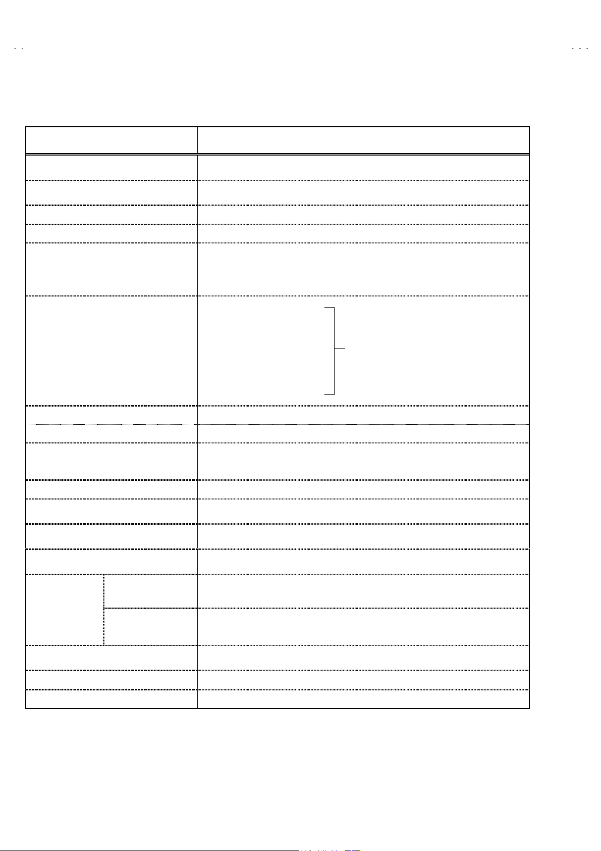
SPECIFICATIONS
Items Contents
Dimensions (W××××H××××D)
Mass
TV RF System CCIR(M)
Color Sound System NTSC / BTSC System (Multi Channel Sound)
TV Receiving Channels and Frequency
VL Band
VH Band
UHF Band
CATV Receiving Channels and Frequency
Low Band
High Band
Mid Band
Super Band
Hyper Band
Ultra Band
Sub Mid Band
TV/CATV Total Channel 181 Channels
Antenna terminal 75Ω(VHF/UHF) Terminal, F-Type Connector
Intermediate Frequency
Video IF Carrier
Sound IF Carrier
Color Sub Carrier 3.58MHz
Power Input
Power Consumption
Picture Tube
High Voltage
Speaker
Audio Power Output
External Input
Video
Audio (R/L)
S-Video
component
Audio Output Variable
Fixed
Digital- In DVI 25pin connector Digital-In terminal is not compatible with computer signal.
38-1/8”×30-3/8”×24-1/8” inch (967mm×770mm×610mm) [AV-36P903
34-5/8”×27-5/8”×22-1/4” inch (877mm×699mm×565mm) [AV-32P903
187.0 Ibs (85.0 kg) [AV-36P903
145.2 Ibs (66.0 kg) [AV-32P903
(02~06) 54MHz~88MHz
(07~13) 174MHz~216MHz
(14~69) 470MHz~806MHz
(02~06, A-8) by (02~06&01)
(07~13) by (07~13)
(A~1) by (14~22)
(J~W) by (23~36)
(W+1~W +28) by (37~64)
(W+29~W +84) by (65~125)
(A8, A4~A1) by (01, 96~99)
45.75MHz
41.25MH z (4.5MHz)
120V AC, 60Hz
215W
36” (90cm)/32”(80cm) Measured Diagonally
32kV±1.0kV (at zero beam current)
2”×4-3/4” (5cm×12cm) Oval type×2
5W +5W
1Vp-p, 75Ω
500mVrms ( -4dBs ), High Impedance
Y: 1Vp-p Positive (negative sync provided, when terminated with 75Ω)
p-p
C: 0.286V
/ PR : 0.7Vp-p, 75Ω
P
B
More then 0~1000mVrms (+2.2dBs), LOW Impedance(400Hz when modulated 100%)
500mVrms(-4dBs) Low Impedance (400Hz when modulated 100%)
(burst signal, when terminat ed with 75Ω)
/Y]
/Y]
(54MHz~804MH z)
/Y
/Y
]
]
Remote Control Unit RM-C324G (AA/R6/UM-3 battery×2)
Design & specifications are subject to change without notice.
2
No.52008
Page 3
A
A
SAFETY PRECAUTIONS
V-36P903
V-32P903
1. The design of this product contains special hardware, many
circuits and components specially for s afety purposes. For
continued protection, no changes should be made to the
original design unless authorized in writing by the manufacturer.
Replacement parts must be identical to those used in the
original circuits. Servic e should be performed by qualified
personnel only.
2. Alterations of the design or circuitry of the products should not
be made. Any design alterations or additions will void the
manufacturer's warranty and will further relieve the
manufacturer of r esponsibility for personal injury or property
damage resulting therefrom.
3. Many electr ical and mechanical parts in the products have
special safety-related characteristics. These characteristics are
often not evident from visual inspection nor can the protection
afforded by them necess arily be obtained by using
replacement c omponents rated for higher voltage, wattage, etc.
Replacement parts which have these special safety
characteristics are identified in the parts list of Service manual.
Electrical components having such featur es are ident ified
by shading on the schematics and by (!!!!) on the parts list
in Service manual. The use of a substitute replacement which
does not have the same safety characteristics as the
recommended replacement part shown in the parts list of
Ser vice man ual may c aus e s hoc k, fire, or oth er haz ar ds.
4. Use isolation transformer when hot chassis.
The chassis and any sub-chassis c ontained in some products
are connect ed to one sid e of the AC power lin e. An isolati on
transformer of adequate capacity should be inserted between
the product and the AC power supply point while performing
any service on s ome products when the HOT chassis is
exposed.
5. Don't short between the LIVE side ground and ISOLATED
(NEUTRAL) side ground or EARTH side ground when
repairing.
Some model's power circuit is partly different in the GND. The
differenc e of the GND is shown by the LIVE : (") side GND,
the ISOLATED(NEUTRAL) : (#) side GND and EARTH : ($)
side GND. Don't short between the LIVE side GND and
ISOLATED(NEUTRAL) side GND or EARTH side GND and
never measure with a measuring appar atus (osc illosc ope etc.)
the LIVE side GND and ISOLATED(NEUTRAL) side GND or
EARTH side GND at the same time.
If above note will not be kept, a fuse or any parts will be br oken.
6. If any repair has been made to the chassis, it is recommended
that the B1 setting should be checked or adjusted (See
ADJUSTMENT OF B1 POWER SUPPLY).
7. The high voltage applied to the picture tube must conform with
that specified in Service manual. Excessive high voltage can
cause an increase in X-Ray emission, arcing and possible
component damage, therefore operation under excessive high
voltage conditions should be kept to a minimum, or should be
prevented. If severe arcing occurs, remove the AC power
immediately and det ermine the cause by visual inspection
(incorrect installation, cr acked or melted high voltage harness,
poor soldering, etc.). To maintain the proper minimum level of
soft X-Ray emission, components in the high voltage circuitry
including the picture tube must be the exact replacements or
alternatives approved by the manufacturer of the c omplet e
product.
8. Do not check high voltage by drawing an arc. Use a high
voltage meter or a high voltage probe with a VTVM. Discharge
the picture tube before attempting meter connection, by
connecting a clip lead to the ground frame and connecting the
other end of the lead through a 10kΩ 2W resistor to the anode
button.
9. When service is r equired, obser ve the original lead dr ess.
Extra precaution should be given to assure correct lead dress
in the high voltage circuit area. Where a short circuit has
occurred, those c omponents that indicate evidence of
overheating should be replaced. Always use the
manufacturer's replacement c omponents.
10. Isolation Check
(Safety for Electrical Shock Hazard)
After re-assembling the product, always perform an isolation
check on the expos ed metal parts of the c abinet (antenna
terminals, video/audio input and output terminals, Control
knobs, metal cabinet, scr ewheads, earphone jack, control
shafts, etc.) to be sure the product is s afe to operate without
danger of electrical shock.
(1) Dielectr ic Strength Test
The isolation between the AC primary circuit and all metal parts
exposed to the user, particularly any exposed metal part having
a return path to the chassis should withstand a voltage of
1100V AC (r.m.s.) for a period of one second.
(. . . . W ithstand a voltage of 1100V AC (r.m.s.) to an appliance
rated up to 120V, and 3000V AC (r.m.s.) to an appliance rated
200V or more, for a period of one second.)
This method of test requires a test equipment not generally
fou nd in th e s er vic e trade.
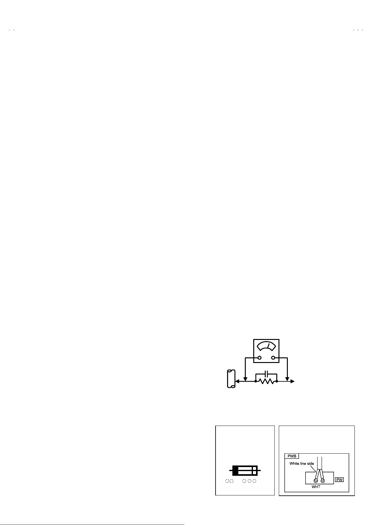
(2) Leakage Current Check
Plug the AC line cord directly into the AC outlet (do not use a
line isolation transformer during this check.). Using a "Leakage
Current Tester", measure the leakage current from each
exposed metal part of the cabinet, particularly any exposed
metal part having a return path to the chassis, to a known good
earth gr ound (water pipe, etc.). Any leakage current must not
exceed 0.5mA AC (r.m.s.).
However, in tropical area, this must not exceed 0.2mA AC
(r.m.s.).
"""" Alternate Check Method
Plug the AC line cord directly into the AC outlet (do not use a
line isolation transformer during this check.). Use an AC
voltmeter having 1000 ohms per volt or more sensitivity in the
following manner. Connect a 1500Ω 10W resistor paralleled
by a 0.15μ F AC-type capacitor between an exposed metal
part and a known good earth ground (water pipe, etc.).
Measure the AC voltage across the resistor with the AC
voltmeter. Move the resistor connection to each exposed metal
part, particularly any exposed metal part having a return path to
the chassis, and measure the AC voltage across the resistor.
Now, reverse the plug in the AC outlet and repeat each
measurement. Any voltage measur ed must not exceed 0.75V
AC (r.m.s.). This corresponds to 0.5mA AC (r.m.s.).
However, in tropical area, this must not exceed 0.3V AC
(r.m.s.). This corresponds to 0.2mA AC (r.m.s.).
AC VOLTMETER
(HAVING 1000
GOOD
EARTH
GROUND
11. High voltage hold down circuit check.
After repair of the high voltage hold down circuit, this circuit
shall be checked to operate c orrectly.
See item "How to check the high voltage hold down
circuit".
This mark shows a fast
operating fuse, the
letters indicated below
show the rating.
0.15μF AC-TYPE
1500
10W
Ω
OR MORE SENSITIVITY)
PLACE THIS PROBE
ON EACH EXPOSED
METAL PART
POWER CORD
REPLACEMENT W ARNING.
Connecting the white line side of power
cord to “WHT” character side.
/V,
Ω
A V
No. 52008
3
Page 4

A
V-36P903
A
V-32P903
FEATURES
■ Multi screen function
• Dual screen (P&P)
Two programs can be seen at once.
• Contents index.
A favorable program can be selected from the nine
preview PIPs on the screen.
■ Provided with twin tuner / twin mode (16:9&4:3mode).
■ Multifunctional remote control permits picture
adjustment.
■ The CH.GUARD function prevents the specific
channels from being selected, unless the “ID
number” is entered.
2
C bus control utilizes single chip ICs.
■ I
■ Adoption of the VIDEO STATUS function.
• The VIDEO STATUS key gives you a choice of 3
picture display settings, including a display of your
own preferences.
STANDARD DYNAMIC THEATER
■ Digital-In
To receive digital broadcasts.
Digital-In will display when the 480p (or 1080i)
picture signal in Digital-In is displayed.
■ Natural Cinema
When you watch the movie or animation, press the
Natural Cinema to adjust the out line of the images
to make thin more sharp.
■ Built-in V-CHIP system.
• This TV is equipped with V-CHIP technology which
enables TV parental guidelines and movie
guideline controls.
■ Closed-caption broadcasts can be viewed.
■ Built-in MTS (
In addition to mono or stereo sound, an MTS
broadcast may also include a Second Audio
Program (SAP).
■ Built-in HYPER-SURROUND system & BBE sound
system.
■ S-VIDEO input terminal for taking best advantage
of Super VHS.
■ Digital Comb filter Improves picture quality.
■ Plug-In menu
The plug-In menu comes up automatically when
you first turn on the TV after plugging it in.
Multi-channel Television Sound
) system.
4
No.52008
Page 5
A
A
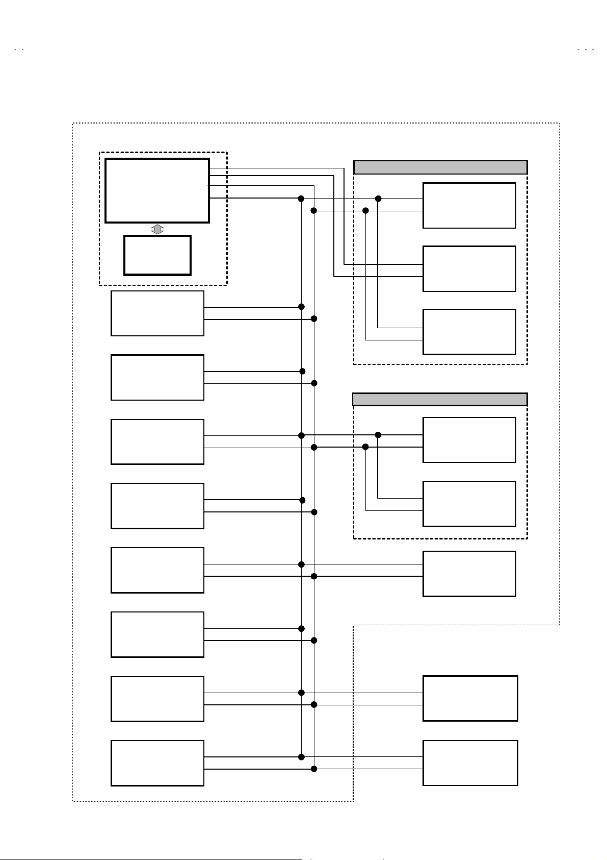
SYSTEM BLOCK DIAGRAM
MAIN PWB
SDA2
SCL2
V-36P903
V-32P903
SUB TUNER (RECEIVER) PWB
MAIN MICROCOMPUTER
IC701
IC703
MEMORY IC
TU101
U / V TUNER
IC501
AV SELECTOR
IC211
HD SYNC
SDA0
SCL0
TU101
U / V TUNER
IC201
MTS & TONE / VOL
CONTROL
IC651
MICOM LATCH
DEF OSC PWB
IC161
DEF CONTROL
IC241
CHROMA
DECODER
IC301
RGB PROCESSOR
IC302
DAC
IC502
MICOM LATCH
IC560
MICOM LATCH
IC212
DEF CONTROL SW
IC151
COMPONENT SW
DIGITAL INPUT
MODULE
I/P MODULE
No. 52008
5
Page 6
A
V-36P903
A
V-32P903
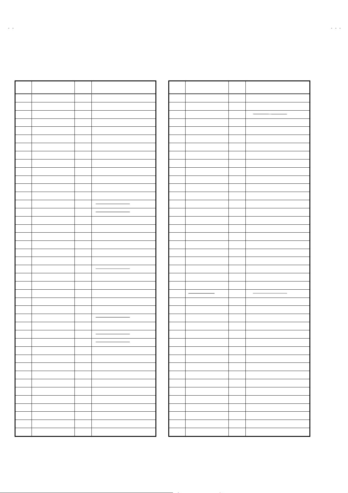
■■■■ MAIN MICON (CPU) FUNCTION
(MIN102H57K)
PIN
№№№№
PIN NAME
1 NC
2 /VSYNC
3 LB_PRO
4 NC
5 /RST
6 NC
7 /TEST
8 YS
9 NC
10 NC
11 A_MUTE
12 /HSYNC
13 M_MUTE
14 OSDXI
15 OSDXO
16 NC
17 AC_IN
18 NC
19 /TU_POW
20 VCOI
21 PDO
22 /IP_RESET
23 YM
24 B
25 LED_POW ER
26 G
27 R
28 VREF
29 IP_ERR
30 IREF
31 COMP
32 AVDD
33 CLL
34 VREFLS
35 SUB_CCD
36 NC
37 VSS
38 MAIN_CCD
39 VREFHS
40 CLH
41 VDD
42 LED_DATA
I/O
I/O
I/OI/O
OOOO
NC
IIII
V.SYNC IN for OSD
IIII
LOW B Protection
-
NC
IIII
Micon Reset input
OOOO
NC
IIII
+3.3V
OOOO
OSD YS OUT
OOOO
Micon test pin
OOOO
NC
OOOO
TV Sound Muting
IIII
H.sync input for OSD
OOOO
Monitor Out Muting
-
-
OOOO
NC
IIII
AC 50/60Hz in
OOOO
NC
OOOO
Tuner Power Control
IIII
LPF input
OOOO
LPF output
OOOO
OOOO
OSD YM out
OOOO
OSD Blue out
OOOO
LED for Power
OOOO
OSD Green Out
OOOO
OSD Red Out
IIII
IIII
AMDP pr ogram load det.
IIII
IIII
IIII
+3.3V
IIII
For Sub CCD
IIII
STD VOL in for Sub CCD
IIII
For Sub CCD
-
NC
IIII
GND
IIII
For main CCD
IIII
STD VOL in for CCD
IIII
For main CCD
OOOO
+3.3V
OOOO
Front control Data
FUNCTION
PIN
№№№№
PIN NAME
43 LED_CLOCK
44 LED_ON_TIMER
45 SB01
46 SBD1
47 SBT1
48 INC
49 ECO.RST
50 ROT COIL L
51 ROT COIL R
52 H_BLK
53 SN_ COIL_R
54 SN_ COIL_L
55 NC
56 I2C.STOP
57 TU2_A/D(AFC2)
58 /LOB_POW
59 NC
60 /POWERGOOD
61 /MECA_ON
62 /MAIN_POW
63 NC
64 /B1 POW
65 AFC1
66 X-RAY
67
68 KEY2
69 KEY1
70 SCL1
71 SDA1
72 REMO
73 NC
74 VSS
75 OSC2
76 OSC1
77 VDD
78 SCL0
79 NC
80 SDA0
81 SCL2
82 SDA2
83 NC
84 P MUTE
I/O
I/O
I/OI/O
OOOO
OOOO
OOOO
IIII
IIII
IIII
OOOO
OOOO
OOOO
OOOO
OOOO
Terrestrial Magnetism Sensor
OOOO ↑
OOOO
OOOO
IIII
OOOO
IIII AV CompulinkⅢInput
IIII
IIII
OOOO
-
OOOO
IIII
IIII
OOOO
IIII
IIII
OOOO
I/O
I/O
I/OI/O
IIII
OOOO
IIII
OOOO
IIII
IIII
OOOO
OOOO
I/O
I/O
I/OI/O
OOOO
IIII
-
OOOO
FUNCTION
F. LED CLK
LED on timer
Use for
Use for ON board W riting
NC
Eco Rest
Picture rotation
Picture rotation
H.BLK
NC
I2C BUS STOP
Tuner2 gain input
LOB power control
Power Condition Check
Machine SW Interrupt
MAIN POWER CONTROL
NC
B1 POWER CONTROL
AFC main in
X-ray detection
Front Key input 2
Front Key input 1
I2C BUS (CLK) for E2PROM
I2C BUS (SDA) for E2PROM
Remocon IN
NC
GND
4MHz OSC
4MHz OSC
+3.3V
I2C BUS (CLK) for General
NC
I2C BUS (SDA) for General
I2C BUS (CLK) for MTS
I2C BUS (SDA) for MTS
NC
Picture muting
6
No.52008
Page 7
A
A
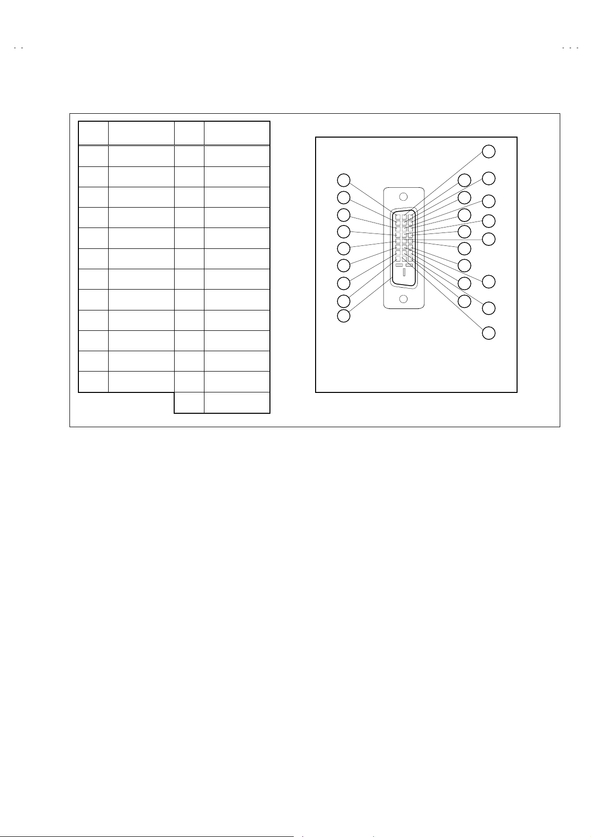
■■■■ DIGITAL-IN TERMINAL FUNCTIONS
V-36P903
V-32P903
PIN
No.
1 RX2- 13 RX3+
2RX2+14 5V
3 GND2/ 4 15 GND
4RX4-16HTPLG
5 RX4+ 17 RX0-
6 SCL 18 RX0+
7 SDA 19 GND0/5
8NC20RX5-
9 RX1- 21 RX5+
10 RX1+ 22 GNDC
11 GND1/3 23 TXC+
12 RX3- 24 TXC-
PIN NAME
PIN
No.
25 GND
PIN NAME
PIN ASSIGNMENT
17
18
19
20
21
22
23
24
25
9
10
1
2
11
3
12
4
13
5
6
14
7
8
15
16
No.52008
7
Page 8
A
V-36P903
A
V-32P903
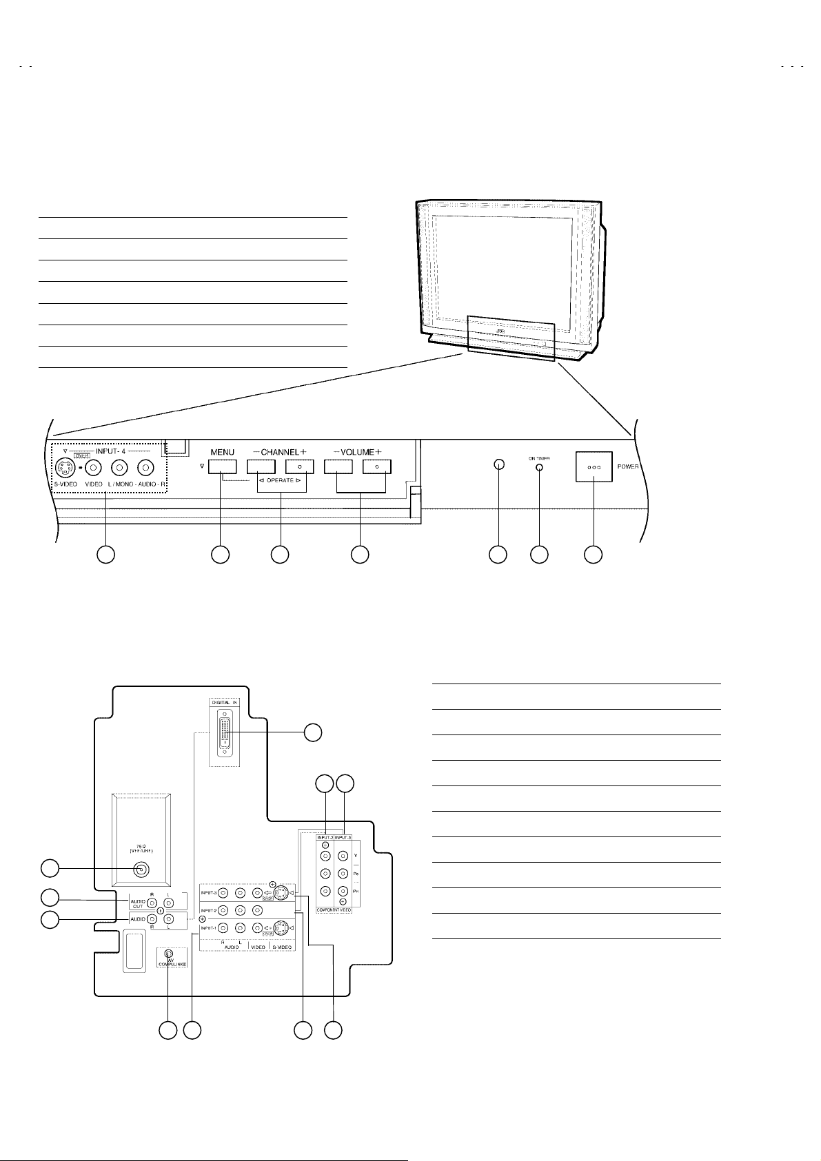
FUNCTIONS
" FRONT PANEL
① INPUT -4 terminals (S -Video, Video, Audio L/MONO / R)
② MENU button
③ CHANNEL ----/++++ button or OPERATE button
④ VOLUME ----/++++ button
⑤ SENSOR Remote control
⑥ POWER & ON TIMER lamp
⑦ POWER(Main) button
1 2 3 4 5 6 7
" AV TERMINAL (REAR)
1
2
3
5
6 7
① ANT 75Ω(VHF/UHF) Terminal
② AUDIO OUTPUT (L/R) terminal
③ AUDIO INPUT (L/R) Terminal
④ AV COMPULINKⅢ Jack
⑤ DIGITAL-IN Terminal
⑥ INPUT-2 (Y/P
⑦ INPUT-3 (Y/PB/PR) Terminal (Component Video )
⑧ INPUT-1 Terminal (S-Video / Video /Audio L/R)
⑨ INPUT-2 Terminal (Video/Audio L/R)
⑩ INPUT-3 Terminal (S-Video / Video /Audio L/R)
B/PR)Terminal (Component Video )
4 8 9 10
8
No.52008
Page 9
A
A
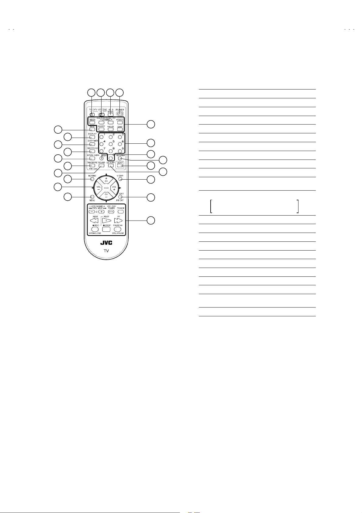
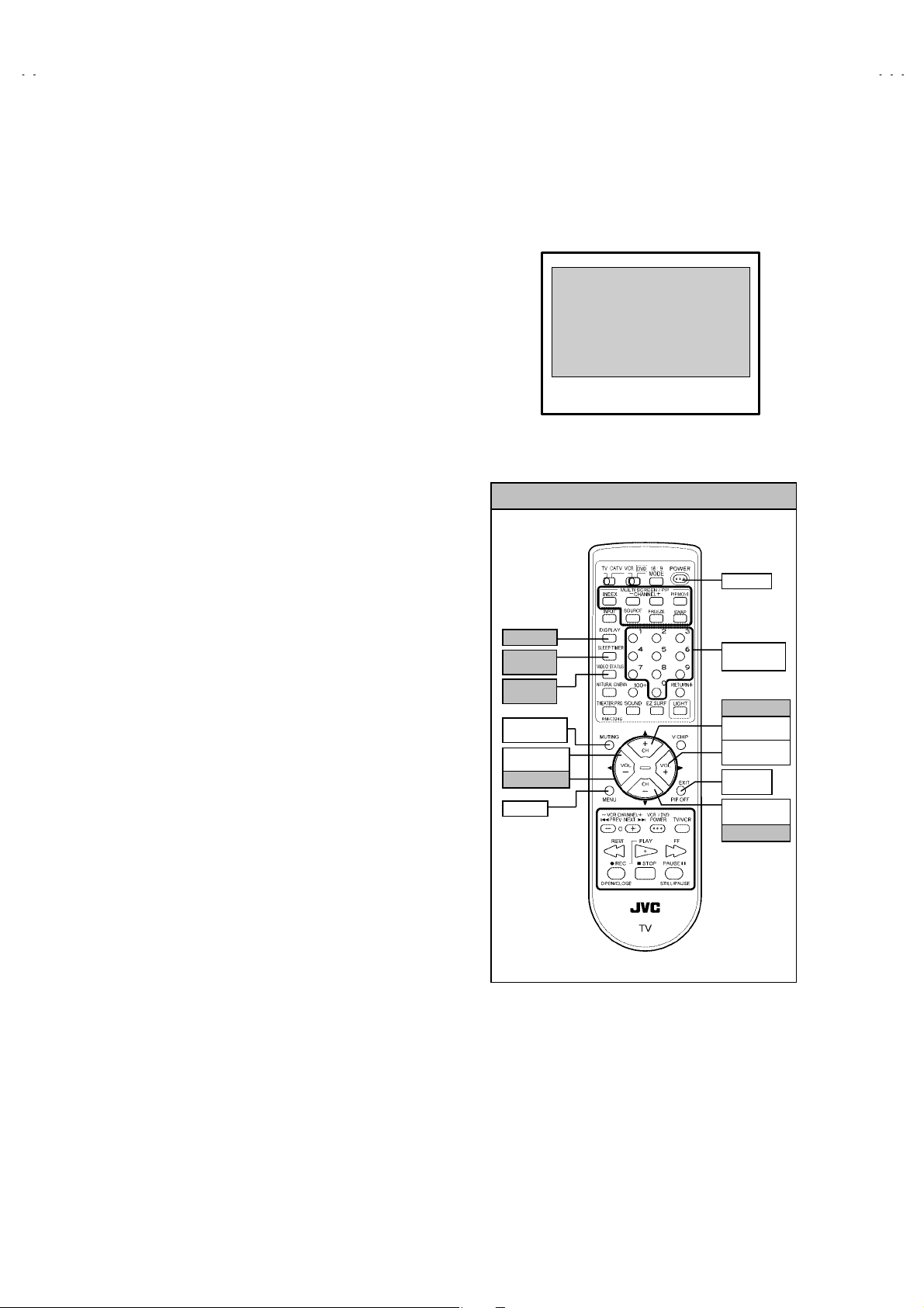
" REMOTE CONTROL (RM-C324G)
V-36P903
V-32P903
13
10
11
1 2 3 4
12
5
6
7
8
9
18
21
14
15
16
17
23
19
20
22
1TV / CATV switch
2VCR / DVD switch
316 : 9 MODE Key
4POWER Key
5DISPLAY key
6SLEEP TIMER Key
7VIDEO STATUS Key
8NATURAL CINEMA Key
9THEATER key
ASOUND key
BFUNCTIONS Key
(CH +/-, VOL +/- & SERVICE MODE)
CMULTI SCREEN / PIP Key
INDEX / -CHANNEL+ / PIP/MOVE
SOURCE / FREEZ / SWAP
DINPUT Key
ENUMBERS Key
F100+ Key
GRETURN+ Key
HLIGHT Key
IMUTING Key (memory Key)
JV-CHIP Key
KEXIT / PIP OFF Key
LMENU Key
MVCR / DVD Key
For VCR/DVD operation Keys
NEZ SURF Key
Keys
No.52008
9
Page 10
A
V-36P903
A
CO
CHASSIS
C
V-32P903
SPECIFIC SERVICE INSTRUCTIONS
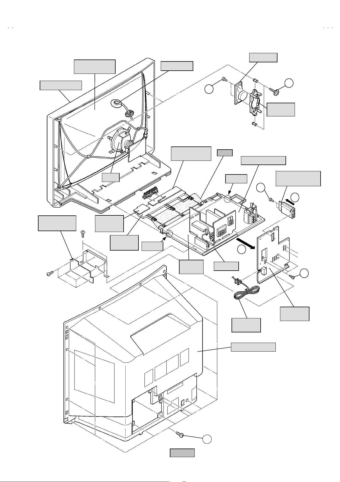
DISASSEMBLY PROCEDURE
REMOVING THE REAR COVER
" Unplug the power supply cord.
1. Remove the 15screws marked !!!! as s hown in Fig.2.
2. Remove the r ear cover toward you.
* When reinstalling the rear cover, carefully push it inward after
inserting the chassis into the rear cover gr oove.
REMOVING THE TERMINAL BOARD
" After removing the rear cover.
1. Remove the 5 screws marked """" as shown in Fig.2.
2. When you pull out the TERMINAL BOARD in the direction of
arrow marked #### as shown in Fig.2, it can be removed.
REMOVING THE CHASSIS
" After removing the rear cover.
1. Slightly raise the both sides of the chassis by hand and remove
the 2 claws under the both sides of the chassis from the front
cabinet.
2. Draw the chassis backward along the rail in the arrow direction
marked #### as shown in the Fig.2.
(If necessary, take off the wire clamps, connectors etc.)
* W hen conducting a check with power supplied, be sure to
confirm that the CRT earth wire is connected to the CRT
SOCKET PWB and MAIN PWB or DEF.POWER PWB.
REMOVING THE CONTROL BASE
" Af ter removing the rear cover and the chassis.
1. While pushing down the claws marked $$$$ as shown in Fig.1.
2. Remove the CONTROL BASE in the arrow direction
marked%&
%&.
%&%&
( If necessary, take off the wire clamps, c onnect ors etc. )
REMOVING THE SPEAKER / SPEAKER HOLDER
" After removing the rear cover and the chassis.
1. Remove the 2 screws marked ''''as shown in Fig.2, then remove
the speaker holder toward you.
2. Remove the 2 screws marked ((((as shown in Fig.2.
3. Draw the speaker toward you.
4. Follow the same steps when removing the other hand speaker.
REMOVING THE DIGITAL INPUT MODULE PWB
" After removing the rear cover and terminal board.
1. Remove the 2 screws marked ))))as shown in Fig.2.
2. Remove the DIGITAL INPUT MODULE PW B in the arrow
direction marked ****.
* If necessary, take off the wire clamps, connectors etc.
CHECKING THE PW BOARD
1. To check the backside of the circuit board.
(1) Pull out the chassis. (Refer to REMOVING THE CHASSIS).
(2) Erect the chassis vertically so that you can easily check the
backside of the PW Board.
[CAUTION]
• When erecting the chassis, be careful so that there will be no
contact with other PWB.
• Before turning the power on, make sure that the CRT earth wire
and other connectors are properly connected.
WIRE CLAMPING AND CABLE TYING
1. Be sure to clamp the wire.
2. Never remove the cable tie used f or tying the wires together.
Should it be inadvertently removed, be sure to tie the wires with
a new cable tie.
E
D
LAW
BASE
NTROL
BASE
10
AV-36P903/Y
AV-32P903/Y
DIGITAL INPUT MODULE
POWER CORD
36P903CP-S
32P903CP-S
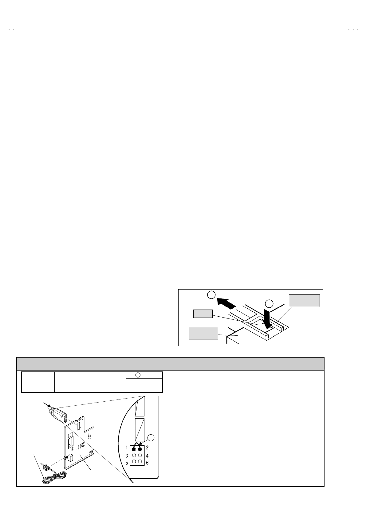
CAUTION AT DISASSEMBLY
SSB-7836A- M2
SSB-7837A- M2
TERMINAL BOARD
*
wire
WJJ0247-001A
*
SB
connect or
Fig. 1
" Prior to disassembly, unplug the power cord from the wall
outlet without fail. (Turn the power “off”.)
" Short the SB connector (1) pin and (2) pin of the digital input
unit. (At the time of assembling)
" Before the rear cover is inserted into the cabinet, release the
short-circuit bet ween the SB connector (1) pin and (2) pin of
the digital input unit.
" After releasing the short-circuit between the SB connectors, do
not turn the pow er on until the rear cover is inserted into the
cabinet.
* Negligenc e in carrying out the above steps may cause the
inactivation of the TV.
No. 52008
Page 11
A
A
HOLDER
CRT
(
)
PICT URE TUBE
V-36P903
V-32P903
SPEAKER
ANODE CAP
FRONT CABINET
LINE
FILTER PWB
DY
POWER
SW PWB
CONTROL
BASE
CLAW
FRONT
CONTROL PWB
G
(×2)
Fig.1
DEF. POWER PWB
CLAW
C
H
(×2)
F
(×2)
SPEAKER
DIGITAL INPUT
MODULE PWB
I
MAIN
PWB
CHASSIS
B
(×5)
TERM INAL
BOARD
POWER
CORD
REAR COVER
A
Fig.2
(×15)
No. 52008
11
Page 12
A
V-36P903
A
V-32P903
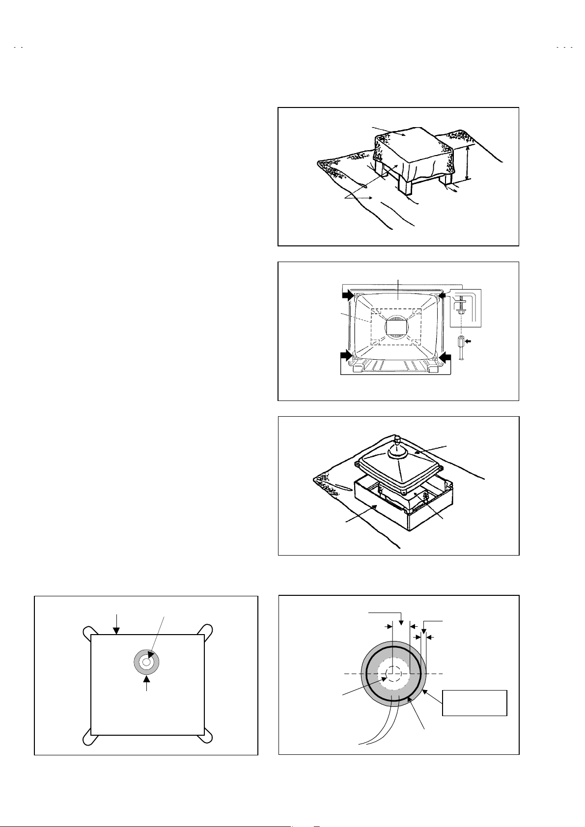
REMOVING THE CRT ( Picture Tube )
∗ Replacement of the CRT should be perf ormed by 2 or more
persons.
• After removing the rear cover, chassis etc.,
1. Putting the CRT change table on s oft cloth, the CRT change
table should also be covered with such soft cloth (shown in
Fig.3).
2. While keeping the surface of CRT down, mount the TV s et on
the CRT change table balanced will as shown in Fig.4.
3. Remove 4 screws marked by arrows with a box type
screwdriver as shown in Fig.4.
• Since the cabinet will drop when screws have been removed,
be sure to support the cabinet with hands.
4. After 4 scr ews have been r emoved, put the cabinet slowly on
cloth (At this time, be carefully so as not to damage the front
surface of the c abinet) shown in Fig.5.
• The CRT should be assembled acc ording to the opposite
sequence of its dismounting steps.
∗ The CRT change table should preferably be smaller that the
CRT surface, and its height be about 35cm.
CRT CHANGE TABLE
APPROX.
35cm
CLOTH
Fig. 3
CRT
CRT
CHANGE
TABLE
BOX
TYPE
SCREW
DRIVER
COATING OF SILICON GREASE FOR ELECTRICAL
INSULATION ON THE CRT ANODE CAP SECTION.
• Subsequent to replacement of the CRT and HV transf ormer or
repair of the anode c ap, etc. by dismounting them, be sur e to
coat silicon grease for electric al insulation as shown in Fig.6.
Wipe around the anode button with clean and dry cloth. (Fig.6)
Coat silicon grease on the section around the anode button. At
this time, take care so that any silicon greases dose not sticks
to the anode button. (Fig.7)
★★★★ Silicon grease product No. KS - 650N
CRT
Anode button
Silicon grease
coating
CABINET
Approx.
20mm (Do not
coat greas e on
this section
Anode button
(N o stic king of
silicon gr ease)
Fig. 4
CRT
CRT
CHANGE TABLE
Fig. 5
Silicon grease
should be coated
by 5mm or more
from the outside
diameter of anode
cap.
Coating position
of silicon grease
Anode c ap
Fig. 6 Fig. 7
12
No. 52008
Page 13
A
A
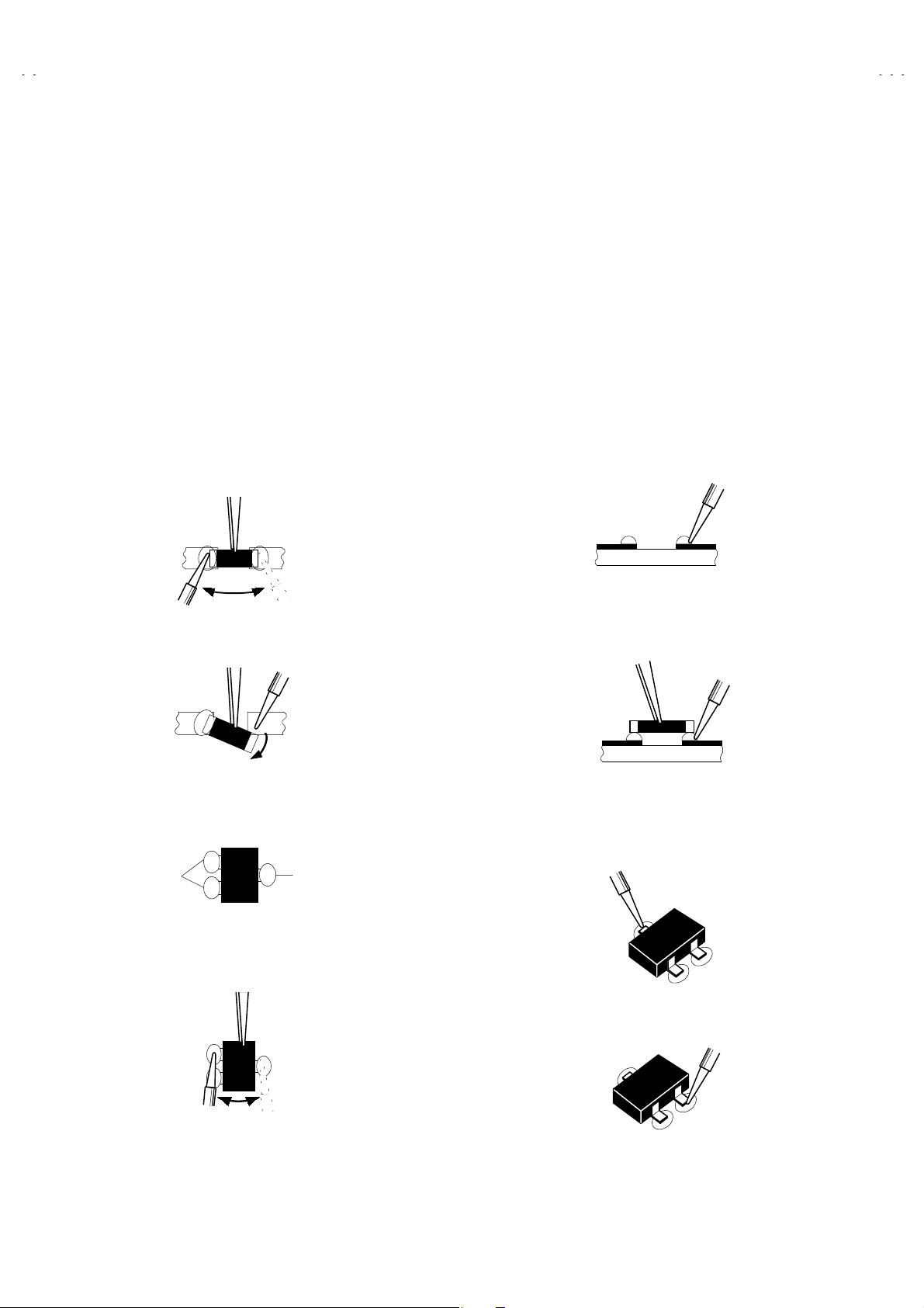
REPLACEMENT OF CHIP COMPONENT
! CAUTIONS
1. Avoid heating f or more than 3 s econds.
2. Do not rub the electrodes and the resist parts of the pattern.
3. When removing a chip part, melt the solder adequately.
4. Do not reuse a chip part after removing it.
! SOLDERING IRON
1. Use a high insulation soldering iron with a thin pointed end of it.
2. A 30w s oldering iron is recommended for easily removing parts.
! REPLACEMENT STEPS
1.
How to remove Chip parts
#### Resistors, capacitors, etc
(1) As shown in the figure, push the part with tweezers and
alternately melt the solder at each end.
(2) Shift with tweezers and remove the chip part.
#### Transistor s, diodes, variable r esistors, etc
(1) Apply extra s older to each lead.
V-36P903
V-32P903
2. How to install Chip parts
#### Resistors, capacitors, etc
(1) Apply solder to the pattern as indicated in the figure.
(2) Grasp the chip part with tweezers and place it on t he solder.
Then heat and melt the solder at both ends of the chip part.
#### Transistor s, diodes, variable r esistors, etc
(1) Apply solder to the pattern as indicated in the figure.
(2) Grasp the chip part with tweezers and place it on t he solder.
(3) First solder lead
as indicated in the figure.
A
SOLDER
(2) As shown in the figure, push the part with tweezers and
alternately melt the solder at each lead. Shift and remove the
chip part.
Note : After removing the part, remove remaining solder from the
pattern.
SOLDER
No. 52008
A
(4) Then solder leads
A
C
and C.
B
C
B
B
13
Page 14
A
V-36P903
A
V-32P903
MEMORY IC REPLACEMENT
1. Memory IC
This model uses a memory IC.
This memory IC stores data for proper operation of the video
and deflection circuits.
When replacin g t he m em or y IC , b e sur e to use an IC
containing this (initial value) data.
2. Memory IC replacement procedure
(1) Power off
Switch the power off and disconnect the power cord from
the wall outlet.
(2) Replace the memory IC
Initial value must be entered into the new IC.
(3) Power on
Connect the power cord to the wall outlet and switch the
power on.
(4) SERVICE MENU setting
1) Press SLEEP TIMER key and, while the indic ation of
SLEEP TIMER 0 MIN is being displayed, press
DISPLAY key and VIDEO STAT US key on the remote
control unit (Fig.2) simultaneously.
2) The SERVICE MENU screen as shown in Fig.1 is
displayed.
3) Verif y what to set in the SERVICE MENU, and s et
whatever is necessary (Fig.1).
Refer to the SERVICE ADJUSTMENT for setting.
4) Press the EXIT key twice to r eturn normal screen.
(5) Receive channel setting
Refer to the OPERATING INSTRUCTIONS (USER’S
GUIDE) and set the receive channels (Channels Preset) as
described.
SERVICE MENU
SERVICE MENU
SERVICE MENU
SERVICE MENU SERVICE MENU
1.PICTURE/SOUND
1.PICTURE/SOUND 7.I2C BUS
1.PICTURE/SOUND1.PICTURE/SOUND
2.YC SEP
2.YC SEP 8.PP
2.YC SEP2.YC SEP
3.LOW LIGHT
3.LOW LIGHT 9.IP
3.LOW LIGHT3.LOW LIGHT
4.HIGH LIGHT
4.HIGH LIGHT 0.SELF-CHK
4.HIGH LIGHT4.HIGH LIGHT
5.RF AFC
5.RF AFC
5.RF AFC5.RF AFC
6.PIP
6.PIP
6.PIP6.PIP
Fig.1
SERVICE MENU SELECT KEY
DISPLAY
SLEEP
TIMER
VIDEO
STATUS
MEMORY
(MUTING)
VALUE
SELECT(-)
FUNCTION
MENU
7.I2C BUS
7.I2C BUS7.I2C BUS
8.PP
8.PP8.PP
9.IP
9.IP9.IP
0.SELF-CHK
0.SELF-CHK0.SELF-CHK
POWER
NUMBERS
key
FUNCTION
ITE M
SELECT(▲)
VALUE
SELECT(+)
EXIT /
PIP OFF
ITE M
SELECT(▼)
FUNCTION
(6) User settings
Check the user s etting items according to the steps
described in the after page.
Where these do not agree, refer to the OPERATING
INSTRUCTIONS (USER’S GUIDE) and set the items as
described.
Fig.2
14
No. 52008
Page 15
A
V-36P903
A
V-32P903
LAST MEMORY OF FACTORY
NTSC / 525p(ED) system
Item
TINT COLOR PICTURE BRIGHT DET AIL
STANDARD 00 00 00 00 00 LOW 00
THATER 00 00 00 00 00 HIGH 00
DYNAMIC 00 00 +30 00 +03 HIGH 00
HD(1080i) system
Item
TINT COLOR PICTURE BRIGHT DET AIL
STANDARD 00 00 00 00
THATER 00 00 00 00
DYNAMIC0000+20000HIGH00
SETTING VALUE
SETTING VALUE
DIGI. NOISE
(CLEAR)
DIGI. NOISE
(CLEAR)
00
00
COLOR
(TEMPERATURE)
COLOR
(TEMPERATURE)
LOW
00 LOW 00
CH. SETTING ( CHANNEL SUMMARY) [ ○○○○:Add. CH / ――
―― :Erase CH]
――――
BAND Ch Display Setting BAND Ch Display Setting
02 ○ N27 ――
――
――
――――
○
○
○
○
――
――
――――
SUPER
○
――
――
――――
○
――
――
――――
○
○
○
――
――
――――
――
――
――――
SUBMID
○
○
○
○
○
HYPER
○ ――
○
――
――
○ ――
――
―― ――
ULTRA
○
―― ――
――
O28
P29――――――
Q30――――――
R31
S32
T33――――――
U34――――――
V35――――――
W36
A-7 93
A-6 94
A-5 95
A-4 96
A-3 97
A-2 98
A-1 99
A-8 01
W+11 47
W+12 48
W+17 53
―― ――
――――
W+23 59
――
―― ――
――――
W+29 65
―― ――
――――
W+51
―― ――
――――
W+78
―― ――
――――
W+84
―― ――
――――
―― ――
――――
―― ――
――――
――
―― ――
――――
―― ――
――――
――
―― ――
――――
―― ――
――――
――
―― ――
――――
VHF
VHF
UHF
MID
SUPER
03
L
04
05
06
07
08
09
H
10
11
12
13
14
36
41
46
63
69
A14
B15
C16
D17
E18
F19――――――
G20――――――
H21
I22――――――
J23――――――
K24
L25――――――
M26――――――
――
――――
○
――
――
○
○
――
――
――
○
――
――
――――
――
――
――――
――
――
――――
○
○
(EXCEPT 32”TV)
○
――
――
――――
――
――
――――
○
(EXCEPT 32”TV)
○
(EXCEPT 32”TV)
○
――
――――
○
――
――――
――
――
――――
――
――――
――
――――
――
――――
――
――――
――
――――
――
――――
No. 52008
15
Page 16

A
V-36P903
A
V-32P903
LAST MEMORY OF FACTORY
(USER SETTING)
Setting item Setting value Setting item Setting value
POWER
CHANNEL
BBE
VOLUME
INPUT
OFF
AIR-02
ON
10
TV
NOISE MUTING
AUDIO OUT
BASS
TREBLE
BALANCE
ON
FIX
CENTER
CENTER
CENTER
DISPLAY
NATURAL CINEMA
16 : 9 MODE
VIDEO STATUS
HYPER SURROUND OFF
PIP SOURCE
PIP POSITION
TINT / COLOR / PICTURE
/BRIGHT / DETAIL
VSM
COLOR TEMPERTURE
DIG. NOISE CLEAR
OFF
OFF
4 : 3
DYNAMIC
CH-04
BOTTOM ( LEFT SIDE )
Refer to setting of Video
status memory at packing
ON
HIGH
CENTER
MTS
TV SPEAKER
SET CLOCK
ON / OFF TIMER
LANGUAGE
CLOSED CAPTION
FRONT PANEL LOCK
AUTO SHUT OFF
AUTO TUNER SET UP
DIGITAL-IN( at 480p signal input)
CHANNEL SUMMARY
V-CHIP
SET LOCK CODE
AUTO DEMO
STEREO
ON
Unnecessary to set
NO
ENG
OFF ( CC1 / T1 )
OFF
OFF
Unnecessary to set
SIZE 1
Refer to Last memory
(CH. summary)
OFF
Unnecessary to set
OFF
16
No. 52008
Page 17

A
A
SERVICE ADJUSTMENTS
V-36P903
V-32P903
ADJUSTMENT PREPARATION
1. You can make the necessary adjust ments for this unit with
either the Remote Control Unit or with the adjustment tools
and parts as given belo w.
2. Adjustment with the Remote Control Unit is made on the
basis of the initial setting values, however, the new setting
values which set the screen to its optimum condition may
differ from the initial settings.
3. Make sure that AC power is turned on correctly.
4. Turn on the power for set and test equipment before use, and
start the adjustment procedur es after waiting at least 30 minutes.
5. Unless otherwise specified, prepare the most suitable reception
or input signal for adjustment.
6. Never touch any adjustment setting value which are not
specified in the list for this adjustment.
7. Presetting before adjustment.
Unless otherwise specified in the adjustment instructions, preset
the following functions with the remote contr ol unit:
" Setting position
VIDEO STATUS STANDARD
BASS, TREBLE, BALANCE CENTER
HYPER SURROUND OFF
TINT, COLOR, PICTURE,
BRIGHT, DETAIL
CENTER
ADJUSTMENT EQUIPMENT
1. DC voltmeter (or digital voltmeter)
2. Oscilloscope
3. Signal generator (Pattern generator) [NTSC / HD / ED / HDCP]
****【【【【HD:1080i / ED:525p=4 80p / DVD:525i=480i 】】】】
4. Remote control unit
5. TV audio multiplex signal generator.
6. Frequency c ounter
ADJUSTMENT ITEMS
Adjustment items
% B1 POWER SUPPLY Check
% X-RAY protec tor chec k
% FOCUS adjustment
% DEF. adjustment
V. CENTER & TRAPE / V. HEIGHT & V. LIN. adjustment
H. WIDTH / H.POSI. / EW. CORNER, UPPER /
LOWER & TRAPEZUM adjustment
HDCP DISPLAY POSITION adjustment
CH. PROGRAM LIST & AREA, DISPLAY POSITION
adjustment
% V/C adjustment
WHITE BALANCE (Low Light & High Light) adjustment
PIP WHITE BALANCE (High Light) adjustment
BRIGHT / CONT. in sub screen adjustment
SUB BRIGHT / SUB CONT. / COLOR /
TINT in sub screen / COLOR / TINT B-Y AXIS GAIN
% MTS adjustment
CAUTION
Never change the initial setting value any adjustments except for those that are
designated in the adjustment procedures.
In case where you have made undesignated adjustments by mistake, never press the
MUTING key on the remote control unit.
Whenever you had not pressed the MUTING key, you would be able to recover the initial
value by switching the POWER SW (on/off) key.
No. 52008
17
Page 18

A
V-36P903
A
V-32P903
MAIN PARTS (PWB) LOCATION
A : CRT SOCKET PWB
B : DY PWB (Within DY )
C:MAIN PWB
D : DEF. POWER PWB
E : LINE FILTER PWB
F : JACK PWB
G:DEF OSC PWB
H : FRONT CONTROL PWB
I : POWER SW PWB
J : DIGITAL INPUT MODULE PWB
B
K : I/P M OD ULE PWB
L : SUB TUNER (RECEIVER) PWB
A
J
TERMINAL
BOARD
H
D
G
KL
C
POWER
CORD
FBT
I
TUNER1
E
18
TUNER2
No. 52008
F
Page 19

A
A
ADJUSTMENT LOCATION (1/2)
POWER SW PWB FRONT CONTROL PWB
V-36P903
V-32P903
FRONT
FRONT
FRONT
F
POWER
SW
B
LED IND.
SP
MAIN PWB
SENSOR
Y
F
CN010
R
VIDEO
Y
(+)(-)
VOL. CH.
G
(+)(-)
MENU
H
L/MONO
S-V
DEG. COIL
FRONT
G
M
H
SUB TUNER
IC701
CPU
MEMORY I C
IC703
(RECEIVER)
PWB
B
CN001
DEF. POW ER
PWB
CN002
J
CRT SOCKET PWB
TOP
FUSE
PW
LINE FILTER
PWB
TUNER 1
E1
TUNER2
(TU101)
CN005
CN005
No. 52008
CN007
AF
I/P MODULE
PWB
JACK PWB
CN006
E
CN010
CN003
DEF OSC PW B
S1
19
Page 20

A
V-36P903
A
V-32P903
ADJUSTMENT LOCATION (2/2)
TOP
DIGITAL INPUT MODULE PWB
REAR
IC
LINE FILTER
PWB
FRONT
CONTROL
PWB
MAIN PW B
IC701
CPU
H
MEMORY IC
IC703
DC
SY
CRT SOCKET PWB
TOP
TP-R
Q
E
SB
CONNECT
TP-G
A J
TP-B
CRT SOC KET
E2
(parts side)
VM
DY
TP-E1
DEF. POWER PWB
B
DEG COIL
CN001
CN002
J
DEG
FRONT
JACK PWB
CN006
E
CN003
CN010
HV
DY
DEF OSC PWB
FBT
A
H.(FOCUS) VR
H.(FOCUS) VR
H.(FOCUS) VRH.(FOCUS) VR
V.FOCUS VR
V.FOCUS VR
V.FOCUS VRV.FOCUS VR
SCREEN VR
SCREEN VR
SCREEN VRSCREEN VR
S1
1Pin : TP-E ( )
2Pin : X-ray2
3Pin : X-ray1
4Pin : NC
5Pin : TP-91(B1)
S1
5555
1111
20
No. 52008
Page 21

A
A
BASIC OPERATION OF SERVICE MENU
1. TOOL OF SERVICE MENU OPERATION
Operate the SERVICE MENU with the REMOTE CONTROL UNIT.
2. SERVICE MENU ITEMS
In general, basic setting (adjustments) items or verific ations are perf ormed in the SERVICE MENU.
1. PICTURE / SOUND・・・・・・・・・ This sets the setting values of the VIDEO/CHROMA /AUDIO and DEFLECTION circuits.
2. YC SEP ・・・・・・・・・・・・・・・・・・・ This is used when the YC mode is adjusted. [Do not adjust]
3. LOW LIGHT ・・・・・・・・・・・・・・・ This sets the setting values of the WHITE BALANCE circuit.
4. HIGH LIGHT ・・・・・・・・・・・・・・・ This sets the setting values of the WHITE BALANCE circuit.
5. RF AFC CHK ・・・・・・・・・・・・・・ This is used when the IF VCO is adjusted. [ Do not adjust]
6. PIP ・・・・・・・・・・・・・・・・・・・・・・・ This is used when the OUTPUT of PIP data is adjusted. [Do not adjust]
2
C BUS・・・・・・・・・・・・・・・・・・・ This is used when ON/OFF if the I2C BUS c ontrol is stop. [Do not adjust]
7. I
8. PP ・・・・・・・・・・・・・・・・・・・・・・・ This sets the setting value of the output of P&P data. [Do not adjust]
9. IP ・・・・・・・・・・・・・・・・・・・・・・・・ This sets the setting value of the IP circuit. [Do not adjust]
0. SELF-CHK・・・・・・・・・・・・・・・・・ This sets the self checking of the TV circuit.
3. Basic Operations of the SERVIC E MENU
(1) How to enter the SERVICE MENU.
Press SLEEP TIMER key and, while the indication of “SLEEP
TIMER 0 MIN.” is being displayed, press DISPLAY key and
VIDEO STATUS key on the remote control unit simultaneous ly
to enter the SERVICE MENU screen as shown in the Fig.1.
(2) SERVICE MENU screen selection
Press the ten key to s elect any of the following items.
SERVICE MENU
1.PICTURE/SOUND 7.I2C BUS
2.YC SEP 8.PP
3.LOW LIGHT 9.IP
4.HIGH LIGHT 0.SELF-CHK
5.RF AFC
6.PIP
V-36P903
V-32P903
1.PICTURE/SOUND 7.I2C BUS
2.YC SEP 8.PP
3.LOW LIGHT 9.IP
4.HIGH LIGHT 0.SELF-CHK
5.RF AFC
6.PIP
(3) Enter any setting mode
" 1. PICTURE / SOUND mode
1) Select 1. PICTURE / SOUND items with the number key
and press the function (
) key to select the
▲/▼
1. PICTURE/SOUND mode. Then the screen will be
displayed as shown in figure in the sub sequent page.
2) Then the settings or verifications can be perf ormed.
" 2.YC SEP, 3.LOW LIGHT, 4.HIGH LIGHT, 5.RF AFC,
6.PIP, 7.I
2
C BUS, 8.PP, 9.IP and 0.SELF-CHK mode
1) If you select any of 2.YC SEP 3.LOW LIGHT 4.HIGH
LIGHT 5.R F AFC 6.PIP, 7.I
2
C BUS, 8.PP, 9.IP and
0.SELF-CHK mode items, and the numbers key is press ed
from SERVICE MENU, the each screen will be displayed
as shown in the figure in the sub sequent page.
2) Then the settings or verifications can be perf ormed.
DISPLAY key
SLEEP TIMER
key
VIDEO STATUS
key
MEMORY key
(MUTING)
MENU key
Fig. 1
KEY FUNCTION of SERVICE MENU
NUMBERS key
EXIT key
(PIP OFF)
FUNCTION key
(▲/▼) & ( / )
Select the setting value
Select the setting Item
No. 52008
21
Page 22

A
V-36P903
A
V-32P903
FUNCTION
VOL. -/+ key
FUNCTION
CH -/+ key
SERVICE MENU
SERVICE MENU
1.PICTUR E/SOUND 7.I2C BUS
2.YC SEP 8.PP
3.LOW LIGHT 9.IP
4.HIGH LIGHT 0.SELF-CHK
5.RF AFC
6.PIP
1.PICTURE/SOUND
***** *****
NTSC
A01 001
A01
*********
*** *** ******* ******
A16
~~~~
DO NOT ADJUST
LOW
HW-BAL
PIP
***
4.HIGH LIGHT
5.RF AFC
T
UNER
**
AFC
**
F
INE
***
6.PIP
DO NOT ADJUST
PIP001
028
~~~~
YC001
~~~~1
S01
D01
F01
F
07
~~~~
S60
S01
*** **********
*** *** **********
20
D
~~~~
I2C
***
D01
*** *********
*** *** **** **** *
F65
~~~~
01
*** *********
*** *** ******* **** *
PPA001
DO NOT ADJUST
2.YC SEP
***
YC001
*** *** *** ***
IP001
3.LOW LIGHT 0.SELF-CHK
7.I2C BUS
8.PP
***
9.IP
*** ********** *
PPA001
PPT001
PPD001
PPB001
PPM001
PPS001
IP001
017
~~~~
014
~~~~
054
~~~~
048
~~~~
038
~~~~
041
~~~~
107
~~~~
LW-BAL
22
No. 52008
Page 23

A
A
(4) Setting method
1) UP / DOW N (
Select the SETTING ITEM.
▲/▼) function key on remote control unit.
2) LEFT / RIGHT ( / ) function key on remote control unit
Setting (adjust) the setting value of the SETTING.
When the MUTING key is pressed the setting value
will be stored ( memorized).
3) EXIT key
Returns to the previous scr een.
(5) Releasing SERVICE MENU
1) After returning to the SERVICE MENU upon completion
of the s etting work, press the EXIT key again.
SIGNAL
SYSTEM
SIGNAL
SYSTEM
SETTING
ITEM
1. PICTURE/SOUND
NTSC FULL DYNAMIC LOW
A01 001 OFF F RAME
**** *** *******
~~~~
A16 / S0 1
D20 / F01
~~~~
~~~~
S52
F65
~~~~
A01
D01
2. YC SEP
YC001
***
*** *** *** *** ** *
WHITE BALANCE
VIDEO STATU S
SETTING VALUE
DO NOT ADJUST
SETTING IT EM
~~~~
YC001
YC107
SETTING VALUE
V-36P903
V-32P903
" WHITE BALANCE setting
The setting for 3.LOW LIGHT and 4.HIGH LIGHT are described in the
WHITE BALANCE page of ADJUSTMENT.
KEY FUNCTION of SERVICE MENU
H.LINE OFF
H.LINE ON
G.CUT OFF (▲)
R.CUT OFF
R.DRIVE
R.CUT OFF
R.DRIVE
MEMORY key
(MUTING)
MENU key
FUNCTION key
(▲/▼) & ( / )
(▲)
(▼)
Select the setting value
Select the setting Item
G.CUT OFF (▼)
B.CUT OFF
B.DRIVE
B.CUT OFF
B.DRIVE
RETURN key
(PIP OFF)
(▲)
(▼)
WHITE BALANCE
■■■■
3. LOW LIGHT
LW-BAL
4. HIGH LIGHT
HW-BAL
5. RF AFC
TUNER 2
AFC ON
FINE
***
SETTING IT EM
SETTING IT EM
DO NOT ADJUST
(NOTE)
TUNER 1 (main)/2(SUB: PIP)
AFC Select ON/OFF
FINE FineTuning(-77
AFC ON:Auto Setti ng
~~~~
+77)
No. 52008
23
Page 24

A
V-36P903
A
V-32P903
6.PIP
(Do not adjust)
SETTING ITEM
~~~~
(PIP001
PIP028)
SETTING VALUE
PIP
PIP001
***
PIP
PIP008
6.PIP setting
1) FUNCTION (
2) FUNCTION ( /
) key ・・・・・・・・・・・・・・・・・・・・・ Select the setting Item.
▲/▼
) key ・・・・・・・・・・・・・・・・・・・・・ Select the setting value.
3) MUTING Key ・・・・・・・・・・・・・・・・・・・・・・・・・・・・・ Setting value will be stored.
4) EXIT key・・・・・・・・・・・・・・・・・・・・・・・・・・・・・・・・・ Returns to the service menu.
5) MENU key ・・・・・・・・・・・・・・・・・・・・・・・・・・・・・・・ Releasing the servic e menu.
8.PP
(Do not adjust)
PPA001
PPA017/PPT001
~~~~
~~~~
PPD001
PPD054/PPB001
~~~~
PPM038/PPS001
PPM001
SETTING ITEM
SETTING VALUE
~~~~
~~~~
~~~~
PPT014
PPB048
PPS041
***
VALUE
ITEM
9.IP
(Do not adjust)
SETTING ITEM
~~~~
(IP001
IP107)
SETTING VALUE
PPA001
***
***
*** ***
NTSC OFF FRAM
**
**
** **
8.PP / 9.IP setting
1) FUNCTION(
2) FUNCTION ( /
) key・・・・・・・・・・・・・・・・・・・・・ Select the setting Item
▲/▼
) key ・・・・・・・・・・・・・・・・・・・・ Select the setting value.
3) SLEEP TIMER key ・・・・・・・・・・・・・・・・・・・・・・・ Skip the each setting Item.
4) MUTING Key ・・・・・・・・・・・・・・・・・・・・・・・・・・・・ Setting value will be stored.
5) EXIT key ・・・・・・・・・・・・・・・・・・・・・・・・・・・・・・・・ Returns to the service menu.
6) MENU key ・・・・・・・・・・・・・・・・・・・・・・・・・・・・・・ Releasing the service menu.
0.SELF-CHK DISPLAY
Press 0 key of remot e control that checks the circuit
operating status and in event of malfunction displays
stores the data in memory. (as shown in figure)
24
No. 52008
IP001
***
***
*** ***
NTSC OFF FRAM
0.SELF-CHK
XRAY NG2 OCP NG2
XRAY NG2 OCP NG2
XRAY NG2 OCP NG2XRAY NG2 OCP NG2
LOB OK TIM OK
LOB OK TIM OK
LOB OK TIM OKLOB OK TIM OK
SYNC M:OK S:OK HD:NG
SYNC M:OK S:OK HD:NG
SYNC M:OK S:OK HD:NGSYNC M:OK S:OK HD:NG
MEM OK AVSW OK
MEM OK AVSW OK
MEM OK AVSW OKMEM OK AVSW OK
VCD NG2 BS OK
VCD NG2 BS OK
VCD NG2 BS OKVCD NG2 BS OK
AIO OK YC OK
AIO OK YC OK
AIO OK YC OKAIO OK YC OK
TUN OK GCR OK
TUN OK GCR OK
TUN OK GCR OKTUN OK GCR OK
PP NG4 IP OK
PP NG4 IP OK
PP NG4 IP OKPP NG4 IP OK
***
***
*** ***
Page 25

A
A
INITIAL SETTING VALUE OF SERVICE MENU
1. Adjustment of the SERVICE MENU is made on the basis of the initial setting values; however, the new setting values which set the
screen in its optimum condition may differ from the initial setting.
2. Do not change the initial setting values of the setting items NOT LISTED IN ADJUSTMENT.
3. The (*1 or *2)marked items in f ollowing table, it is NO REQUIREMENT for adjustment. If values had change by the missing, set the
initial values in the following table.
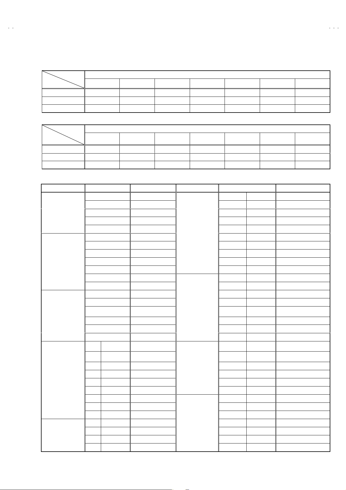
■■■■SOUND MODE
Item
No.
Item name
Variable
range
initial setting
value
Item
No.
Item name
Variable
range
A01 NOISE DET. 0 / 1 001 A09 5FH MON 0 / 1 000
A02 INPUT LEVEL 0 ~ 63 032 A10 SAP VCO 0 ~ 63 034
A03 FH MONITOR 0 / 1 000 A11 INPUT GAIN 0 / 1 000
A04 STEREO VCO 0 ~ 63 035 A12 FIL OFFSET -128 ~ +127 000
A05 PILOT CAN 0 / 1 000 A13 BBE BASS -128 ~ +127 000
A06 FILTER 0 ~ 63 029 A14 BBE TREBLE -128 ~ +127 000
A07 LOW SEP 0 ~ 63 027 A15 BASS -128 ~ +127 -005
A08 HI SEP 0 ~ 63 028 A16 TREBLE -128 ~ +127 -008
initial setting
value
V-36P903
V-32P903
■■■■DEFLECTION MODE
Item
No.
D01
D02
D03
D04 *1
D05
D06
D07
D08
D09
D10 *1
D11 *1
D12 *1
D13 *1
D14
D15 *2
D16
D17 *1
D18 *1
D19 *1
D20 *1
Item name Variable range
V-HEIGHT 0~127 STANDARD -1 +2 -42
EW PARABORA 0~63 STANDARD +2 +1 1
H-WIDTH
V S-CORRECTION 0~63 STANDARD 35 +35 +35 +35
V-LINEARITY 0~63 STANDARD +2 0 -3
V CENTER
TRAPEZIUM 0~63 STANDARD +3 +1 -1
EW CORNER LOWER
EW CORNER UPPER 0~15 STANDARD 0 +1 +1
V EHT
H EHT 0~7 STANDARD 1 ( 1 ) ( 1 ) ( 1 )
EHT GAIN 0~7 STANDARD 5 ( 5 ) ( 5 ) ( 5 )
TEXT CO NTR OL
H CENTER 0~255 STANDARD +2 +30 0
HORIZONTAL
FREQUENCY
H.BLK 0~63 STANDARD 0 0 0
OSD OFFSET
COMPULSION
TWIN SCREEN
COMPULSION
DEF RST OUTPUT
COMPULSION 1080i 0 / 1 STANDARD 0 0 0 0
****
(
1:Fixed value /
****
2:Offset (-107) v alue for HD D15 value)
NTSC
INDEX
( 9 screen )
0~63
4 : 3 PIP
STANDARD 0 +1 1
*1 *1 *1
0~63
0~15
0~7
STANDARD +3 -3 -2
STANDARD 0 0 0
STANDARD 3 ( 3 ) ( 3 ) ( 3 )
*1 *1 *1
*1 *1 *1
*1 *1 *1
0~15
0~255
-127~28
0~6 STANDARD 0 0 0 0
0 / 1 STANDARD 0 0 0 0
STANDARD 0 ( 0 ) ( 0 ) ( 0 )
STANDARD
STANDARD 0 0 0
*1 *1 *1
*2 *2 *2
---
*1 *1 *1
*1 *1 *1
*1 *1 *1
*1 *1 *1
(1/3)
16:9
No. 52008
25
Page 26

A
V-36P903
A
V-32P903
■■■■DEFLECTION MODE (2/3)
Item
No.
D01
D02
D03
D04 *1
D05
D06
D07
D08
D09
D10 *1
D11 *1
D12 *1
D13 *1
D14
D15 *2
D16
D17 *1
D18 *1
D19 *1
D20 *1
Item name Variable range
V-HEIGHT 0~127 STANDARD 0 -42 -42
EW PARABORA 0~63 STANDARD +1 -1 -1
H-WIDTH 0~63 STANDARD 0 +1 +1
V S-CORRECTION
V-LINEARITY 0~63 STANDARD -1 -3 -3
V CENTER
TRAPEZIUM 0~63 STANDARD 0 -2 -1
EW CORNER LOWER
EW CORNER UPPER 0~15 STANDARD 0 +1 +1
V EHT 0~7 STANDARD 3 ( 3 ) ( 3 ) ( 3 )
H EHT
EHT GAIN 0~7 STANDARD 5 ( 5 ) ( 5 ) ( 5 )
ADJUSTMENT
H CENTER 0~255 STANDARD -30 -30 +1
HORI FREQ
ADJUSTMENT
H. BLK
OSD OFFSET -127~128 STANDARD 0 0 0
COMPULSION
TWIN SCREEN
COMPULSION
DEF RST OUTPUT
COMPULSION 1080i 0 / 1 STANDARD 0 0 0 0
0~63
0~63
0~15
0~7
0~15
0~255 STANDARD -- 0
0~63
0~6 STANDARD 0 0 0 0
0 / 1 STANDARD 0 0 0 0
NTSC
4 : 3
STANDARD 35 +35 +35 +35
STANDARD -3 -4 -3
STANDARD 0 0 0
STANDARD 1 ( 1 ) ( 1 ) ( 1 )
STANDARD 0 ( 0 ) ( 0 ) ( 0 )
STANDARD 0 0 0
ED
4 : 3
ED
16 : 9
*1 *1 *1
*1 *1 *1
*1 *1 *1
*1 *1 *1
*1 *1 *1
*2 *2 *2
*1 *1 *1
*1 *1 *1
*1 *1 *1
*1 *1 *1
720p
16 : 9
■■■■DEFLECTION MODE (3/3)
Item
No.
D01
D02
D03
D04 *1
D05
D06
D07
D08
D09
D10 *1
D11 *1
D12 *1
D13 *1
D14
D15 *2
D16
D17 *1
D18 *1
D19 *1
D20 *1
Item name Variable range
V-HEIGHT 0~127 STANDARD 0 -42 0 -42 -42
EW PARABORA
H-WIDTH 0~63 STANDARD 0 +1 0 +1 +1
V S-CORRECTION 0~63 STANDARD 35 ( 35 ) ( 35 ) ( 35 ) ( 35 ) ( 35 )
V-LINEARITY 0~63 STANDARD -1 -2 -2 -3 -2
V CENTER 0~63 STANDARD -3 -4 -4 -4 -5
TRAPEZIUM
EW CORNER LOWER 0~15 STANDARD 0 0 0 0 0
EW CORNER UPPER
V EHT 0~7 STANDARD 3 ( 3 ) ( 3 ) ( 3 ) ( 3 ) ( 3 )
H EHT 0~7 STANDARD 1 ( 1 ) ( 1 ) ( 1 ) ( 1 ) ( 1 )
EHT GAIN
ADJUSTMENT 0~15 STANDARD 0 ( 0 ) ( 0 ) ( 0 ) ( 0 ) ( 0 )
H CENTER
HORI FREQ
ADJUSTMENT
H. BLK 0~63 STANDARD ( 0 ) ( 0 ) ( 0 ) ( 0 ) ( 0 )
OSD OFFSET
COMPULSION
TWIN SCREEN
COMPULSION
DEF RST OUTPUT
COMPULSION 1080i 0 / 1 STANDARD 0 ( 0 ) ( 0 ) ( 0 ) ( 0 ) ( 0 )
0~63
0~63
0~15
0~7
0~255
0~255 ST ANDARD -----
-127~128
0~6 STANDARD 0 ( 0 ) ( 0 ) ( 0 ) ( 0 ) ( 0 )
0 / 1 ST ANDARD 0 ( 0 ) ( 0 ) ( 0 ) ( 0 ) ( 0 )
NTSC
4 : 3
STANDARD +1 -1 +1 -1 -1
4 : 3
( SIZE1 )
16 : 9
( SIZE1 )
*1 *1 *1 *1
STANDARD 0 -2 0 -2 -2
STANDARD 0 +1 0 +1 +1
*1 *1 *1 *1
*1 *1 *1 *1
STANDARD 5 ( 5 ) ( 5 ) ( 5 ) ( 5 ) ( 5 )
*1 *1 *1 *1
*1 *1 *1 *1
STANDARD 0 -1 +62 +62 -35
*2 *2 *2 *2
STANDARD ( 0 ) ( 0 ) ( 0 ) ( 0 ) ( 0 )
*1 *1 *1 *1
*1 *1 *1 *1
*1 *1 *1 *1
*1 *1 *1 *1
HDCP
4 : 3
( SIZE2 )
16 : 9
( SIZE2 )
720p
*1
*1
*1
*1
*1
*2
*1
*1
*1
*1
26
No. 52008
Page 27

A
V-36P903
A
V-32P903
■■■■PICTURE MODE
Item
No.
S01
S02
( HD / 720p / HDCP )
Item
No.
S01
S02
( NTSC / DVD )
Item
No.
S03
Item name
SUB COLOR 0~127 73 75 71 73 74 79 75 69 71 76 69 74
SUB TINT 0~127 69 65 65 60 71 67 78 71 72 71 80 78
Item name
SUB BRIGHT
SUB CONT RAST 0~127 75 72 67 66 +3 +3 -1 -1 -7 -7 -15 -15
Item name
SUB BRIGHT 0~255 128 128 126 130 ----124 125 128 128 ----
( NTSC / DVD / ED )
Variable
range
Variable
range
0~255
Variable
range
(1/2)
NTSC DVD (525i / 480i) ED (480p / 525p)
Standard Theater Standard Theater Standard Theater
32” 36” 32” 36” 32” 36” 32” 36” 32” 36” 32” 36”
(2/2)
HD (1080i) / 720p HDCP
Standard Theater
32” 36” 32” 36” 32” 36” 32” 36” 32” 36” 32” 36”
63 68 59 63 -20 -20 -20 -20 -15 -15 -14 -14
480p (525p) 1080i / 720p
Standard Theater Standard Theater
(1/3)
NTSC DVD (525i / 480i)
4 : 3 16 : 9 4 : 3 16 : 9
Standard Theater Standard Theater Standard Theater Standard Theater
32” 36” 32” 36” 32” 36” 32” 36” 32” 36” 32” 36” 32” 36” 32” 36”
SUB CONT RAST 0~127 89 96 62 62 ----91 95 61 59 ----
S04
SUB BRIGHT OFFSET
S05
CUB CONTRAST
S06
OFFSET
( ED / HD / 720p )
-128~127 ----
-128~127 ----
0000
-15 -15 -7 -7
----
----
0000
-15 -15 -7 -15
ED (480p / 525p) HD (1080i) / ED (480p / 525p) 720p
Item
No.
S03
S04
S05
S06
( MULTI / HDPC )
Item name
SUB BRIGHT 0~255 ----121 121 124 125 ----
SUB CONT RAST 0~127 ----81 83 57 58 ----
SUB BRIGHT OFFSET -128~127 +1 -1 +2 -2 ---- -2 -3 -2 -6
CUB CONTRAST
OFFSET
Variable
range
-128~127
Standard Theater Standard Theater Standard Theater
32” 36” 32” 36” 32” 36” 32” 36” 32” 36” 32” 36”
+8 +9 +3 +3
4 : 3 16 : 9 16 : 9
----
-10 -5 0 +5
MULTI HDCP
Item
No.
S03
Item name
SUB BRIGHT 0~255 ----------------
Variable
range
9 PICTURES 480p (4:3) 480p / 1080i (16:9) 720p (16:9)
Standard Theater Standard Theater Standard Theater Standard Theater
32” 36” 32” 36” 32” 36” 32” 36” 32” 36” 32” 36” 32” 36” 32” 36”
(2/3)
(3/3)
SUB CONT RAST 0~127 ----------------
S04
SUB BRIGHT OFFSET -128~1270000+5+5+5+5+30+30+31+31+3+3+2+2
S05
CUB CONTRAST
S06
OFFSET
-128~12700000000-4-4-2-2-9-900
No. 52008
27
Page 28

A
V-36P903
A
V-32P903
( NTSC / DVD / ED, HDCP480p / HD / 720p / HDCP1080i / HDCP720p )
Item
No.
B-Y AXIS GA IN
S07
R-Y ANGLE GAIN
S08
G-Y MATRIX SW
S09
( NTSC / DVD)
Item
No.
R Drive 0~255 --128 135 ------125 134 ----
S10
R Drive OFFSET -128~127 +6 +6 --+10 +10 +20 +20 +7 +7 --+13 +13 +18 +18
S11
B Drive 0~255 --170 165 ------169 162 ----
S12
B Drive OFFSET -128~127 +7 +7 ---11 -11 -34 -34 +10 +10 ---12 -12 -32 -32
S13
Item name
Item name
Variable
range
0~63
0~7
0~3
Variable
range
NTSC DVD ED / HDCP4 80p
Standard Theater Standard Theater Standard Theater Standard Theater
32” 36” 32” 36” 32” 36” 32” 36” 32” 36” 32” 36” 32” 36” 32” 36”
16 15 21 18 18 18 17 16 13 11 20 16 6 3 15 13
7700772277223333
1133113311332222
Standard Theater Standard Theater
High Low High Low High Low High Low
32” 36” 32” 36” 32” 36” 32” 36” 32” 36” 32” 36” 32” 36” 32” 36”
NTSC DVD
HD / 720p / HDCP1080i
HDCP720p
(1/3)
( ED / HD / 720p ) (2/3)
ED HD 720p
Item
No.
S10
S11
S12
S13
( HDCP ) (3/3)
Item name
R Drive 0~255 ----------134 149 ------------
R Drive OFFSET -128~127 +2 +2 +9 +9 +12 +12 +10 +10 +2 +2 --+12 +12 +14 +14 +17 +17 +15 +15 +27 +27 +29 +29
B Drive 0~255 ----------171 174 ------------
B Drive OFFSET -128~127 +11 +11 +5 +5 -9 -9 -25 -25 +11 +11 ---9 -9 -26 -26 +22 +22 +11 +11 +2 +2 -15 -15
Variable
range
Standard Theater Standard Theater Standard Theater
High Low High Low High Low High Low High Low High Low
32” 36” 32” 36” 32” 36” 32” 36” 32” 36” 32” 36” 32” 36” 32” 36” 32” 36” 32” 36” 32” 36” 32” 36”
HDCP
Item
No.
S10
S11
S12
S13
Item name
R Drive 0~255 ----------------
R Drive OFFSET -128~127 +2 +2 +9 +9 +12 +12 +10 +10 +2 +2 0 0 +12 +12 +14 014
B Drive 0~255 ----------------
B Drive OFFSET -128~127 +11 +11 +5 +5 -9 -9 -25 -25 +11 +11 0 0 -9 -9 -26 -26
Variable
range
Standard Theater Standard Theater
High Low High Low High Low High Low
32” 36” 32” 36” 32” 36” 32” 36” 32” 36” 32” 36” 32” 36” 32” 36”
480p / 1080p 720p
28
No. 52008
Page 29

A
V-36P903
A
V-32P903
( NTSC / DVD / ED / HD / 720p )
Item
No.
S14
S15
S16
S17
S18
S19
S20
S21
( HDCP )
Item
No.
S14
Item name
R CUT OFF
R CUT OFF OFFSET -128~127 -- 00-- 00-- 000000
G CUT OFF 0~255 71 71 --73 73 --92 92 ------
G CUT OFF
OFFSET
B CUT OFF 0~255 139 139 --153 153 --153 153 ------
B CUT OFF
OFFSET
R CUT OFF SW
B CUT OFF SW
Item name
R CUT OFF 0~255 --------
(1/2)
Variable
range
0~255
-128~127 --+6 +5 --+2 0 ---6 -5 +1 0 +1 -5
-128~127 --+13 0 --+4 0 ---60-40-40
0~3
0~3
NTSC DVD ED / HD 720p
Standard Theater Standard Theater Standard Theater Standard Theater
32” 36” 32” 36” 32” 36” 32” 36” 32” 36” 32” 36” 32” 36” 32” 36”
70 70
11
11
--
--
--
70 70
11
11
--
--
--
70 70
11
11
------
------
------
(2/2)
HDCP
Variable
range
480p / 1080i 720p
Standard Theater Standard Theater
32” 36” 32” 36” 32” 36” 32” 36”
R CUT OFF OFFSET -128~12700000000
S15
G CUT OFF 0~255 --------
S16
G CUT OFF
S17
OFFSET
B CUT OFF 0~255 -------1 -
S18
B CUT OFF
S19
OFFSET
R CUT OFF SW
S20
B CUT OFF SW
S21
( NTSC / DVD / ED / HD / 720p / HDCP480p / HDCP1080i / HDCP 720p )
Item
No.
S22
S23
S24
S25
S26
S27
Item name
BLACK GRAD CORR
START LEVEL
BLACK GRAD CORR
GAIN
WHITE GRAD CORR
START LEVEL
WHITE GRAD CORR
GAIN
WHITE CHARA CORR
START LEVEL
WHITE CHARA CORR
GAIN
-128~127 0 0 -3 -3 -6 -6 -6 -6
-128~127
0~3 --------
0~3 --------
Variable
range
0~15 15 15 15
0~15666
0~15000
0~15 15 15 15
0~15211
0~15
0 0 +4 +4 -1 -1 -1 -1
NTSC DVD
( 32” / 36” ) ( 32” / 36” ) ( 32” / 36” )
321
ED / HD / 720p / HDCP480p
HDCP1080i / HDCP720p
No. 52008
29
Page 30

A
V-36P903
A
V-32P903
( ALL SIGNAL )
Item
No.
S28
S29
S30
S31
S32
S33
S34
( NTSC / DVD/ HD / 720p / HDCP1080i / HDCP720p / ED / HDCP480p)
Item
No.
S35
( ALL SIGNAL )
Item name
ABL GAIN 0~15 15 15
ABL START
ACL GAIN
ACL START
CONTRAST LINK 0 / 1 0 0
BLACK GRADATION
CORRECTION OFF
WHITE GRADATION
CORRECTION OFF
Item name
TINT HD / NTSC 0 / 1
Variable
range
0~15
0~15
0~15
0 / 1 0 1
0 / 1 0 0
Variable
range
Standard Theater
( 32” / 36” ) ( 32” / 36” )
15 15
15 15
00
NTSC / DVD
( 32” / 36” ) ( 32” / 36” ) ( 32” / 36” )
101
HD / 720p / HDCP1080i
HDCP720p
ED / HDCP480p
Item
No.
S36
S37
S38
S39
S40
( NTSC / DVD / ED / HD / 720p / HDCP480p / HDCP1080i / HDCP 720p )
Item
No.
S41
( 16 : 9 / THEATER / PIP / OTHER )
Item
No.
S42
Item name
ABL OFF 0 / 1 0 0
ABL OFF 0 / 1 0 0
DC TRANSMIT
POLARITY
DC TRANSMIT
CORR
BLANKING ON / OFF 0 / 1 0 0
Item name
DC REBIRTH
Item name
ACL CONTROL
Variable
range
0 / 1 1 1
0 / 1 0 0
Variable
range
0~255
Variable
range
0~255
Standard Theater
( 32” / 36” ) ( 32” / 36” )
NTSC DVD
Standard Theater Standard Theater Standard Theater
( 32” / 36” ) ( 32” / 36” ) ( 32” / 36” ) ( 32” / 36” ) ( 32” / 36” ) ( 32” / 36” )
160 120 160 120 150 120
( Inc. 720p / HD / HDCP720p / HDCP1080i )
16 : 9 Theater PIP OTHER
( 32” / 36” ) ( 32” / 36” ) ( 32” / 36” ) ( 32” / 36” )
160 50 0 0
ED / HD / 720p / HDCP480p
HDCP1080i / HDCP720p
30
No. 52008
Page 31

A
A
( ALL SIGNAL )
Item
No.
S43
S44
S45
( NTSC / DVD / OTHER )
Item name
CONT. LOW ER LIMIT -128~127
CONT. UPPER LIMIT -128~127
BRIGHT LOW ER LIMIT -128~127
Variable
range
V-36P903
V-32P903
Standard Theater
32” 36” 32” 36”
-45 -45 -15 -15
+17 +17 +17 +17
-20 -20 -20 -20
Item
No.
EE THEAT ER BRT
S46
EE THEAT ER CONT . -128~127
S47
( ALL SIGNAL )
Item
No.
BRIGHT EE CONT. CORRECTION
S48
REFRAIN EE CONT. CORRECTION 0~31
S49
REFRAIN EE BRIGHT OFFSET
S50
CORR (max)
BRIGHT EE ACL CORR. COEFF. 0~255
S51
REFRAIN EE ACL CORR. COEFF. 0~255
S52
( ALL SIGNAL )
Item
No.
Item name
Variable
range
-128~127
NTSC ( 4 : 3 / 16 : 9 ) DVD ( 4 : 3 / 16 : 9 ) OTHER
( 32” / 36” ) ( 32” / 36” ) ( 32” / 36” )
000
+20 +20 +20
Item name Variable range Common Value
0~31
0~127
Item name Variable range Common Value
7
27
4
85
140
VSM OFF OFFSET
S53
VSM ON LOW -128~127
S54
VSM ON MID
S55
VSM ON HIGH -128~127
S56
VSM ON OFFSET -128~127
S57
VSM ON OFFSET
S58
VSM ON OFFSET -128~127
S59
VSM ON OFFSET
S60
0~225
-128~127
-128~127
-128~127
No. 52008
+5
-20
-10
+10
-2
-1
0
+1
31
Page 32

A
V-36P903
A
V-32P903
■■■■OTHERS MODE
Item
No.
Item name
Variable
Range
Setting
Value
Item
No.
Item name
Variable
Range
F01 E2PROM Ver 1 0~255 026 F32 DIRECT SELECT 2 PIC. 0 / 1 000
F02 E2PROM Ver 2 0~255 002 F33
F03 H.LINE ON (BRIGHT) 0~255 133 F34
CAPTION OSD
OSCSELECT
CH.PROGRAM SEARCH
WA IT T IME
0~7002
0~255 040
F04 H.LINE OFF (BRIGHT) 0~255 125 F35 VSM SHIPPING MODE 0 / 1 000
F05 H.LINE CONTRAST 0~127 095 F36 DNR SET 0~3000
F06 C38 / C41 SW 0 / 1 001 F37 2PICTURE 16:9MODE 0 / 1 000
F07 MODEL SELECT 0~255 040 F38
V/C DECODE
H.MASK SETTING
0 / 3 000
F08 F39 LOUDNESS SW 0 / 1 000
F09 Auto Scroll Adjust 1 0~15 002 F40 POW ER OFF WHITE 0 / 1 000
F10 Auto Scroll Adjust 2 0~15 004 F41 WHITE BACK ON/OFF 0 / 1 000
F11 Auto Scroll Adjust 3 0~15 004 F42
F12 Auto Scroll Adjust 4 0~15 005 F43
Setting
Value
F13 Auto Scroll Adjust 5 0~15 006 F44
F14 Auto Scroll Adjust 6 0~15 007 F45
F15 Auto Scroll Adjust 7 0~15 007 F46
F16 V Scroll MAX (VARI) -128~127 -001 F50
F17 V Scroll MIN (VARI) -128~127 +001 F51
F18 V Scroll MAX (CORR.) -128~127 000 F52
F19 V Scroll MIN (CORR.) -128~127 000 F53 S / N (RF) CORR.WIDTH 0~255 004
F20 V LIN . MAX (CORR.) -128~127 000 F54 S / N (RF) CORR.START 0~255 006
F21 V LIN. MIN (CORR.) -128~127 000 F55 S / N (BS) CORR.WIDTH 0~255 005
F22 V Scroll MAX (VARI) 0~255 000 F56 S / N (BS) CORR.START 0~255 006
F23 V Scroll MIN (VARI) 0~255 000 F57
V-CHIP ON/OFF (CANADA)
F24
EARTH MAGNETIC
F25
CORR. PICTURE
OSD OFFSET
F26
(480p / 720p) (HDCP / 480p)
OSD OFFSET
F27
(1080i / HDCP1080i)
CH.PROGRAM
F28
SEARCH CYCLE
PIP FUNCTION
F29
ON / OFF
0 / 1 001 F58
0~127 127 F59 S / N (S) CORR.WIDTH 0~255 005
0~63 033 F60 S / N (S) START 0~255 006
0~63 018 F61 OCD OFFSET (HORI.) 0~63 045
0~255 010 F62 ATT GAIN 0 / 1 000
0 / 1 001 F63 V.HEIGHT OFFSET -128~127 -006
F30 PIP 2 PICTURE 0 / 1 000 F64
S / N (Comp.)
CORR.WIDTH
S / N (Comp.)
CORR.START
TEXT MODE
CONT.CORR.
0~255 005
0~255 006
-128~127 000
F31 V.CHIP ON OFF 0 / 1 001 F65 -128~127
Item
No.
Item name
Variable
Range
NTSC DVD ED HD 720p
Setting Value
HDCP480p HDCP1080i
F47 SEP.LEVEL 0~3 000 002 002 002 002 --
F48 CLAMP PLUS 0 / 1 000 000 000 001 001 --
F49 HD PHASE 0~63 063 027 030 030 028 --
32
No. 52008
Page 33

A
A
■■■■ADJUSTMENT
B1 POWER SUPPLY check
Item
Check of B1
Power supply
X-RAY protector check
Item
Check of
X-Ray
protector circuit
Measurin g
Instrument
Signal generator
DC Voltmeter
Measurin g
Instrument
Resistor
12kΩΩΩΩ1/6W
±±±±5%
Test point
S1 connector
pin 5 (TP-91)
S1 connector
pin 1 (TP-E)
( #### )
Test point
S1 connector
pin
(X-Ray2)
2222
pin
(X-Ray1)
3333
V-36P903
V-32P903
Adjustment Item Description
1. Input a black and white signal (color off).
2. Connect the DC voltmeter to the S1 connector pin 5
(TP-91) and TP-E( #### ) (S1 connector pin 1).
3. Confirm that the voltage is DC140V±2V .
Adjustment Item Description
1. Connect the following resistors between pin ②②②② & pin
③③③③ of the connector S1.
2. Confirm that the X-RAY protector functions are
activated.
FOCUS adjustment
Item
FOCUS
adjustment
Signal
generator
Horizontal line
Measurin g
Instrument
MODEL No. CRT Resistor
AV-36P903/Y 36V 12.0kΩ±60Ω
AV-32P903/Y 32V 22.0kΩ±60Ω
Test point Adjustment Item Description
H (FOCUS)
(UPPER in FBT)
FOCUS
(CENTER in FBT)
1. Input a crosshatch signal.
2. Select the FULL mode.
3. While watching at the scr een, adjust the H (FOCUS)
VR (Fig.2) to make the horizontal lines as fine and
sharp as possible. (Fig.1)
4. Then adjust the FOCU S VR (Fig.2) to make the
vertical lines as fine and sharp as position. (Fig.1)
5. Make sure that when the screen is darkened, the lines
remain in good focus.
Vertical line
Fig. 1 Fig. 2
No. 52008
H
H(FOCUS) VR
FOCUS
FOCUS V R
SCREEN
SCREEN
33
Page 34

A
V-36P903
A
V-32P903
HORIZONTAL FREQUENCY adjustment
Item
Hor. FRE Q.
adjustment
Measurin g
Instrument
signal
generator
Remote Control
unit
DEFLECTION CIRCUIT adjustment
Item
V. POSITION &
TRAPEZ
V. HEIGHT &V.
LIN.
Adju stment
Screen
Vertical
Center
Measurin g
Instrument
Signal
generator
Pallalel
Test point Adjustment Item Description
D15 : H. FREQ.
D19 : DEF. RST
Test point Adjustment Item Description
D06 : V. CENTER
D07 : TRAPEZ
D01 : V. HEIG HT
D05 : V. LIN.
1. Receive the monoscope signal.
2. Enter the SERVICE MENU.
3. Pr eset the value from 0 to 1 for the D19:DEF. RST in
the SERVICE MODE, then adjust the D15:H. FREQ.
and memorize the data with the MUTING key.
4. For the 720p data, input offset data ( 0 ) or NTSC data.
5. Then receive the HD monoscope and memorize the
data same as Item 3.
6. After adjustment, preset the value from 1 to 0 for the
D19:DEF. RST (Compulsion DEF. RST output) and the
memorize the data same as Item 3.
1. Receive the Full mode cross-hatch signal.
2. Enter the SERVICE MENU.
3. Select the D07:TRAPEZ of the 1.PICTURE/SOUND
mode in the SERVICE MENU with the FUNCTION
(
key and adjust the DO7:TRAPEZ to make the
▼/▲)
vertical lines straight with the FUNCTION ( / ) key.
4. Select t he D06:V. CENTER with the FUNCTION (
key.
5. Adjust the D06:V. CENTER so that the horizontal line
of the vert ical center on the cross-hatch screen is
agreement with the screen center marker. The screen
center markers (Fig.1) are positioned at both side of the
screen vertical center.
6. Readjust the D07:TRAPEZ and adjust each vertical
lines to be positioned equally (pallalel) of the screen
(Fig.1).
* Reconfirm the V. CENTER after adjustment of the
TRAPEZ distortion.
7. Select t he D01:V. HEIGHT of the 1. PICTURE/SOUND
mode in the SERVICE MENU.
8. Adjust the V. Height to squeeze the raster.
▲/▼)
Fig.1
34
No. 52008
Page 35

A
V-36P903
A
V-32P903
Item
Screen
size
(A)
Measurin g
Instrument
Screen size
Picture size 100%
Fig.2
16 : 9 SCREEN
Test point Adjustment Item Description
9. Adjust the vertical screen size to (A) by the D01: V.
HEIG HT with the FUNCTION ( / ) key (Fig.2).
10. Then select the D05:V. LIN. with the FUNCTION
(▲/▼) key, and adjust the linearity of the top (B) and
bottom (B) parts of the scr een to correct (Fig.2).
11. Adjust the setting value to which the offset value of
addendum is added, then confir m adjustment point of
each mode on each NTSC 16 : 9, ED (4:3 / 16:9), 9
screen (INDEX), PIP, 720p.
Mode
Adju st
(A)
Setting
Value
12. If adjustment is different, readjust each mode. Then
memorize the values with the MUTING key of the
remote c ontrol unit.
13. For 9 screen (INDEX), HDCP (SIZE1/2, 16:9, 4:3), add
the offset values.
14. Receive the HD (1080i) monosc ope signal, and adjust
the raster by the same upper way.
15. At the HDCP 1080i, if add the offset values.
4 : 3
(NTSC / ED)
88% 92%
16:9
(NTSC / ED)
(HD720p)
Picture
size
100%
(a)
(B)
(B)
PIP
89%
Fig.3
(a)
(NOTE)
* Do not adjust the D04: V. S-R.
* If it is diff erent V. position after adjusting the V. LIN.,
adjust the V. position (D01, D05, D06) again.
* Memorize the value every time after finishing
adjustments on each mode with Muting key.
Model
Item
(a) 67mm 60mm
AV-36P903
/Y
AV-32P903
/Y
No. 52008
35
Page 36

A
V-36P903
A
V-32P903
Item
H. WI DTH /
H. POSITION /
EW. CORNER,
UPPER/LOWER&
TRAPEZIUM
adjustment
Measurin g
Instrument
Signal
generator
A
Fig.1
Screen size
Test point Adjustment Item Description
D03 : H. WIDT H
D14 : H. POSITION
D02 :
EW. PARABORA
D09: EW. CORNER
UPPER
D08: EW. CORNER
LOWER
D07: TRAPEZIUM
B
C
1. Receive the circle pattern (Fig.1).
2. Enter the SERVICE MENU.
3. Select the D03: H. WI DTH the 1.PICTURE/SOUND
mode in the SERVICE MENU with the FUNCTION
(
key.
▲/▼)
4. Adjust the
shown in Fig. 1.
5. Receive the cross-hatch pattern signal (Fig.2).
6. Adjust the D03: H. WIDT H to make the horizontal size
to C of the picture size as shown in Fig. 2.
7. Adjust the vertical line to straight by the D02:EW.
PARABORA
8. If the CORNER PINCUSHION are too bad, adjust the
D09:EW. CORNER UPPER / D08:EW. CORNER LOWER
and the D07:TRAPEZIUM to get exact corner
pincushion of the cross-hatch pattern.
9. As required repeat above steps 2~8.
10. Adjust the setting value in which the offset value of
addendum is added, then confirm the adjustment point
of each NTSC16:9, ED (4:3/16:9), PIP, 720p (Fig.2).
11. If adjustment is different, readjust each mode. Then
memorize the value with the MUTING key of the
remote c ontrol unit.
12. For the 9 screens (INDEX), HDC P (SIZE1/2, 16:9, 4:3),
add the offset values.
13. Receive the HD cross-hatch signal, and adjust the
raster in the same manner as for above.
14. Adjust the horizontal raster size so that it becomes to
just 90%.
15. At the HDCP 1080i, if add the offset values.
D14:H. POSITION
with the FUNCTION ( / ) key.
to make the
A=B
as
36
Adju st
Setting
Value
Mode
<STRAIGHT>
Picture size 100%
4:3 / 16:9
(NTSC/ED)HD(720p)
91% 89% 91%
Fig.2
( NOTE )
* Memorize the values every time after finishing
adjustments on each time.
* Confirm the H. position by monoscope and if it is
different , readjust the H. position again.
* Repeat the adjustment of the H. SIZE and SIDEPIN
cushion.
PIP
No. 52008
Page 37

A
A
( DISPLAY POSITION adjustment )
Item
HDCP
DISPLAY
POSITION
adjustment
Measurin g
Instrument
DVI Sign al
Generator
Remote
Control unit
4:3 mode
16:9 mode
Test point Adjustment Item Description
DIGITAL- IN
Terminal
D14 : H. C ENT ER
PICTURE
IN CENTER
PICTURE
IN CENTER
1. Input the 480p×640signal to the DIGITAL-IN t erminal.
2. Confirm the aspect ratio 4:3 mode.
3. Select the SIZE 1 in the DIGITAL-IN menu.
4. Enter the SERVICE MENU.
5. Adjust t he D14:H. CE NTER as picture in center.
6. Press the MUTING key and then memorize the data.
7. Press the EXIT key to cancel t he SERVICE mode.
8. Select the 16:9 mode and enter the same adjusted
value of the D14 in 4:3 mode.
9. Press the MUTING key and then memorize the data.
10. Press the EXIT key to cancel the SERVICE mode.
11. Input the 1034i×1920 signal (1080i) with the DVI signal
generator.
12. Enter the SERV ICE MENU.
13. Adjust the D14: H. CENTER as pictu re is center .
14. Press the EXIT key to cancel the SERVICE mode.
15. Input the 720p signal with the DVI signal generator.
16. Enter the SERVICE MENU and adjust the D14 as
picture is center.
17. After storing the data, finish the SERVICE mode.
V-36P903
V-32P903
CH.PROGRAM
LIST/
CH.PROGRAM
AREA
DISPLAY
POSITION
Adju stment
Signal Generator
Remote
Control
unit
Top
Left Right
Bottom
D01 : V. HEIG HT
D03 : H. WIDT H
D06 : V. CENTER
D14 : H. C ENT ER
1. Set up the 9 screen mode.
2. Enter the SERVICE MENU.
3. Select the 1.PICTURE/SOUND item.
4. Adjust the following value of the top & bottom direction
in the left screen by the D0 1:V . HEIGHT and D06:V.
CENTER.
5. Adjust the following value right and left direction by the
D03:H. WIDTH and D14:H. CENTER.
6. Press the MUTING key and memorize the values with
the remote control unit.
PICTURE TOP BOTTOM LEFT RIGHT
9 Screen 90% 65% 80% 75%
No. 52008
37
Page 38

A
V-36P903
A
V-32P903
V / C adjustment
(White Balance)
Item
WHITE
BALANCE
(Low Light)
adjustment
Setting
item
LW-BAL
R CUTOFF B CUTOFF
Measurin g
Instrument
Signal
Generator
Remote Control
unit
3. LOW LIGHT SCREEN
A HORIZONTAL LINE
REMOTE CONTROL UNIT
H. LINE OFFH. LINE ON
1
(▲)(
4
7
2
G CUTOFF
G CUTOFF
(▲)(▲)(▲)
▲
)(
5
8
0
Test point Adjustment Item Description
S20 : R CUTOFF
SW
S14 : R CUTOFF
S16 : G CUTOFF
S21 : B CUTOFF
SW
S18 : B CUTOFF
SCREEN VR
EXIT
3
▲
)
6
B CUTOFFR CUTOFF
9
* Select the STANDARD mode (all “000”) for the
VIDEO STATUS.
1. Input the black and white pattern signal (color off).
2. Confirm that the COLOR TEMP is set at the LOW
mode.
3. Enter the SERVICE MENU of the 1.PICTURE/SOUND
item.
4. Set the initial setting values of the S14, S16, S18, S20,
& S21 item on the SERVICE MENU.
5. Select the LW -BAL mode of the 3.LOW LIGHT item on
the SERVICE MENU.
6. Display a horizontal line by pressing the ①①①① key of the
remote c ontrol unit.
7. Turn the SCREEN VR all the way to the left.
Then turn it gradually clockwise until either one of the
red, blue or green color is faintly vis ible.
8. Use the ④④④④~⑨⑨⑨⑨ keys of the remote control unit and
adjust the other 2 colors to where the a horizontal line
appears white.
9. Then press the MUTING key to memorize the dat a.
10. Press the ②②②② key to r elease t he a horizont al line mode.
11. Switch the input signal to the RASTER pattern signal
from black and white pattern signal.
12. Confirm that the WHITE BALANCE is set at the 3.LOW
LIGHT mode.
13. If there is a gap with the setting values, repeat st eps
5.~10. f or readjustment.
14. For S14, S16, S18, S20, & S21 of the 3.LOW LIGHT
mode of the W HITE BALANCE and the LOW and HIGH
modes of the THEATER mode, refer to the attached
initial setting values.
15. Input the DVD (or HD) video signal to the VIDEO-3
terminal and select the VIDEO-3 with the remote
control unit.
16. Repeat the steps 8. ~ 10. above on the SERVICE
MODE.
17. Confirm that the WHITE BALANCE at the 3.LOW
LIGHT mode has been adjusted properly.
18. For S14, S16, S18, S20, & S21 of the 3.LOW LIGHT
mode of the WHITE BALANCE and the 3.LOW LIGHT
and 4.HIGH LIGHT modes of the THEATER mode,
refer to the listed setting values.
19. If there is a gap with the initial setting values.
20. Repeat the steps 8.~10. for readjustment.
21. Press the MUTING key and then memorize with a
remote c ontrol unit.
(NOTE)
* If white balance of low brightness is different from a
horizontal line, adjust it by using the low-light signal.
Be careful not to be green especially.
38
No. 52008
Page 39

A
V-36P903
A
V-32P903
Item
WHITE
BALANCE
(High Light)
adjustment
Setting
ITEM
Measurin g
Instrument
Signal generator
Remote Control
unit
HW-BAL
Fig.1
Test point Adjustment Item Description
S10 : R DRIVE
S12 : B DRIVE
* Select the STANDARD mode (all "000") on the VIDEO
STATUS.
1. Select the STANDARD mode.
2. Receive the black and white signal (color off).
3. Confirm that the COLOR TEMP is set at the LOW
mode.
4. Enter the SERVICE MENU of the 1.PICTURE/SOUND
item.
5. Select the 4.HIGH-LIGHT mode, and set the initial
setting values of the S10 & S12 item on the SERVICE
MENU.
6. Adjust the S10:R. DRIVE and S12:B. DRIVE so that
the WHITE BALANCE falls within the same values of
the standard s etting values.
7. Make sure that the WHITE BALANCE tracking from the
LOW-LIGHT through the HIGH-LIGHT has been
properly done. (When the black and white signal (color
off) is r eceived, the natural white should be visible.)
8. Input the DVD (or HD) video signal to the VIDEO-3
terminal and select the VIDEO-3 with the remot e
control unit.
9. Repeat the steps 3.~7. above.
10. If there is a gap with the initial setting values, repeat the
steps 3.~7. for readjustment.
11. Press the MUTING key and memorize the data with the
remote c ontrol unit.
REMOTE CONTROL UNIT
(▲)
(▲)
H. LINE
OFF
2
G CUTOFF
(
▲
5
G CUTOFF
8
OSD ON/OFF
H. LINE ON
1
R CUTOFF B CUTOFF
4
7
EXIT
3
)
)
(▲
6
B CUTOFFR CUTOFF
9
0
Fig.2
(
)
▲
(▲)
No. 52008
39
Page 40

A
V-36P903
A
MAIN
SUB
V-32P903
(PIP Adjustment)
Item
PIP
White Balance
(High Light)
adjustment
Measurin g
Instrument
Signal Generator
Remote Control
unit
TWIN SCREEN
screen
(LEFT) (RIGHT)
screen
Fig.1
Test point Adjustment Item Description
F30 : TWIN MODE
(NTSC / NTSC)
PPA01 : PIP
BLUE BACK
PPA13 : R-Y
(Main High-Light)
PPA14 : B-Y
(Main High-Light)
1. Select the PIP mode and receive (Input) the black &
white signal on both of the MAIN & PIP SCREEN.
2. Preset the value to 1 for the F30:NTSC/NTSC TW IN
SCREEN (P&P) in the SERVICE MENU (Fig.1).
3. Preset the value to 00 for the PPA01: PIP BLUE BACK
ON / OFF in the SERVICE MENU.
4. At first, adjust the PPA14:MAIN HIGH LIGHT B-Y and
PPA1 3:M AIN HIGH LIG HT R-Y, then adjust the white
level on the left screen.
5. At first, adjust the PPD42:SUB HIGH- LIG HT R-Y an d
PPD0 39:S UB HIGH- LIG HT B-Y, then adjust the white
level on the right screen in the same manner as for left
screen.
6. Press the MUTING key to memorize the data.
7. Preset (retur n) the value to 0 f or the F30:NTSC/NTSC
twin screen in SERVICE MENU.
8. Select the PIP mode, and preset the value to 40 (Initial
value) for PPA01: PIP BLUE BACK ON / O FF in the
SERVICE MENU.
9. Press the MUTING key and memorize the data with the
remote c ontrol unit.
BRIGHT/CONT .
In SUB SCREEN
adjustment
Remote
Control unit
F30 : NTSC / NTSC
TWIN SCREEN
PPA01 : PIP BLUE
BACK LEVEL
PPD036 :
SUB BRIGHT
PPD037 :
SUB CONT.
1. Select the PIP screen and then receive the MAIN
screen.
2. Enter the SERVICE MENU of the 1.PICTURE/SOUND
Item.
3. Preset the value to 1 for the F30:NTSC/NTSC TW IN
SCREEN (P&P) in the SERVICE MENU.
4. Preset the value to 00 for the PPA01:PIP BLUE BACK
ON/OFF in the SERVICE MENU.
5. Adjust the PPD036:SUB BR IG HT so that the right
screen becomes the same as for the left screen (Fig.1).
6. Adjust the PPD037:SUB CONTRAST so that right
scr een b ecomes the sam e as for the l eft sc reen (Fig.1).
7. If bright was changed, adjust it one more time.
8. Preset the value to 0 for the F30:NTSC/NTSC twin
screen (P&P) in the SERVICE MENU.
9. Select the PIP mode, and preset the value to 40 (initial
data) for the PPA01:PIP BLUE BACK ON/OFF in the
SERVICE MENU.
10. Press the MUTING key and memorize the data with the
remote c ontrol unit.
40
No. 52008
Page 41

A
A
( NTSC / 525i / HD Adjustment )
Item
SUB BRIGHT
adjustment
Measurin g
Instrument
Remote Control
unit
Test point Adjustment Item Description
S03 : SUB BRIGHT 1. Receive the Black & W hite signal.
2. Select the STANDARD, white balance to LOW.
3. Select the 1.PICTURE/SOUND from the value to
SERVICE MENU.
4. Select the S03:SUB BRIGHT with the value to
FUNCTION (
5. Set the initial setting value with the FUNCTION ( / )
key.
6. Select the THEATER LOW mode white balanc e and
repeat the steps 3~5 above.
7. Receive the HD black level pattern and select the
STANDARD, then repeat the steps 3~5 above.
8. Receive the HD black level pattern and select
THEATER mode, then repeat the steps 3~5 above
9. Input the DVD black level pattern to the INPUT 3 and
select STANDARD, then repeat the steps 3~5 above.
10. Input the DVD black level pattern to the INPUT 3 and
select the THEATER, then repeat the steps 3 ~ 5
above.
11. Input the 525i black level pattern, and select the
STANDARD mode, then repeat the steps 3~5 above .
12. Then select the THEATER mode, and repeat the steps
3~5 above.
13. If the brightness is not the best with initial setting value,
make fine adjustment of the S03: SUB BRIG HT until
you get the optimum brightness.
▲/▼
) key.
V-36P903
V-32P903
SUB CONT.
adjustment
Remote Control
unit
S04 : SUB CONT.
1. Select the STANDARD, then c onfirm that white balance
is set at the LOW mode.
2. Enter the SERVICE MENU of 1.PICTURE/SOUND
Item.
3. Select the S04:SUB CONT with the FUNCTION (
key.
4. Set the initial setting value with the FUNCTION ( / )
key.
5. Select the THEATER LOW mode then r epeat the steps
3~4 above.
6. Select the DVD (525i), then repeat the steps 3 ~ 4
above.
7. Select the HD (1080i) pedestal pattern and t hen repeat
the steps 3~4 above.
8. If the contrast is not the best with the initial setting
value, make fine adjustment of the S04:SUB C ONT.
until you get the optimum contrast.
▲/▼
)
No. 52008
41
Page 42

A
V-36P903
A
MAIN
SUB
V-32P903
(NTSC (525i) / 525p / HD(1080i) Adjustment )
Item
COLOR / TINT
in SUB SCREEN
ajustment
Measurin g
Instrument
Signal Generator
OSCILLOSC OPE
screen
Test point Adjustment Item Description
TP-R
F30 : NTSC / NTSC
TWIN SCREE N
PPA01 : PIP BLUE /
BACK LEVEL
PPS01 : SUB
DECODER T INT
PPS04 :
SUB DECODER
COLOR
1. Select the twin screen and receive the COLOR BAR
signal to the sub screen and the PEDESTAL signal to
the main screen (Fig.1).
2. Enter the SERVICE MENU of the 1.PICTURE/SOUND
Item.
3. Preset the value to 1 for the F30:NTSC/NTSC TWIN
SCREEN in the SERVICE MENU.
4. Preset the value to 00 f or the PPA01:PIP BLUE BACK
ON / OFF in the SERVICE MENU.
5. Check the TP-R by using an oscilloscope.
6. Adjust the PPS04:SUB DECODER COLOR, PPS01 :
SUB DECODER TINT to the adjustment point
[V](Fig.2).
screen
7. Preset 0 f or the value to F30:NTSC/NTSC twin screen
in the SERVICE MENU.
8. Select the PIP mode, then preset the value to 40 (initial
data) for the PPA01:PIP BLUE BACK ON/OFF.
Fig.1
9. Press the MUTING key and store the data.
10. Press the EXIT key to cancel the SERVICE mode.
(A)
(Y)(W) (R)
W-Y
Fig.2
W-R
• setting value
Model No.
(-)
0
(+)
AV-36P903/Y +24V +52V
AV-32P903
/Y
Adjustment Point
W-Y W-R
+24V +52V
(A)
(A)
42
No. 52008
Page 43

A
A
( 525i / 525p / HD Adjustment )
V-36P903
V-32P903
Item
COLOR / TINT
B-Y AXIS GAIN
Adju stment
Measurin g
Instrument
Signal
generator
Oscilloscope
Remote control
unit
W
Fig.1
Test point Adjustment Item Description
TP-R
TP-B
TP-E(####)
S01 : SUB COLOR
S02 : SUB TINT
S07 : B-Y AXIS
GAIN
1. Receive the 525i, 75% color bar and s elect the
standard mode.
2. Enter the SERVICE mode of the 1.PICTURE/SOUND
Item.
3. Chec k t he TP-R by using an os ci ll oscope.
4. Adjust the S01:SUB COLOR and S02:SUB TI NT to be
the following setting value A[V] (Fig.3).
5. Select the THEATER and adjust the S01:SUB COLOR
and the S02:SUB TINT to be the f ollowing setting value
B[V] same as above.
6. Check the TP-B by using an oscilloscope.
7. Select the standard and adjust the S07:B-Y AXIS GAIN
to be setting value C[V].
8. Select the THEATER and adjust the S07:B-Y AXIS
(-)
0
(+)
(W-B)(W-Y)Y
B
GAIN to be setting value D[V]
9. Receive the R HD color bar and repeat the steps 3~8
above.
10. Receive the 525p color bar and repeat the steps 3~8
above.
11. Confirm that the low-light is not different after adjusting
color, Tint and B-Y AXIS Gain.
12. If it is green or magenta, adjust the low-light again.
13. If the readjustment is c arried out, set the offset values
again.
(-)
0
W
(W-B)
B
(+)
Fig.2
• AV-36P903 / AV-32P903
Setting
Item
Color Bar
Setting Value A[V] Setting Value B[V] Setting Vaue C[V] Setting Value D[V]
Standard Theater Standard Theater
(W-R) (W-Y) (W-R) (W-Y) (W-B) (W-B)
NTSC +44 +19 +26 +1 +11 +9
HD(1080i) +22+6+9+9 -2 +2
525i +31 +23 +12 +3 -5 -3
525p +31 +21 +18 0 -12 -4
Fig.3
No. 52008
43
Page 44

A
V-36P903
A
V-32P903
Item
COLOR / TINT
B-Y AXIS GAIN
Adju stment
Measurin g
Instrument
Signal
generator
Oscilloscope
Remote control
unit
W
Fig.1
Test point Adjustment Item Description
TP-R
TP-B
TP-E(####)
PPM01 : SUB TINT
PPM04 : SUB
COLOR
S07 : B-Y AXIS
GAIN
1. Input the NTSC COLOR / TINT data 525i, 75% white
COLOR / TINT data offset value (Standard and
theater).
2. Receive the COLOR BA R and then select the
STANDARD mode.
3. Check the TP-R by using an oscilloscope.
4. Enter the SERVICE MODE of the 1.PICTURE/SOUND
Item.
5. Adjust the PPM04:SUB COLOR and PPM01:SUB
TINT to be the f ollowing s etting value A[V]
6. Select the THEATER STATUS and adjust the S01:
SUB COLOR and the S02:SUB TI NT to be the
following setting value B[V] same as above.
7. Check the TP-B by using an oscilloscope.
(-)
0
(+)
(W-B)(W-Y)Y
B
8. Select the STANDARD and adjust the S07: B-Y AXIS
GAIN to be Setting Value C[V]
9. Select the THEATER and adjust the S07:B-Y AXIS
GAIN to be the Setting Value D[V]
10. Copy the PPM01/PPM04 data to the PIP mode.
11. Confirm that the low-light is not different after adjusting
color, TINT and B-Y AXIS GAIN.
12. If it is green or magenta, adjust the low-light again.
13. If the readjustment is c arried out, set the offset values
again.
(-)
0
W
(W-B)
B
(+)
Fig.2
• AV-36P903 / AV-32P903
Setting
Item
Color Bar
Setting Value A[V] Setting Value B[V] Setting Vaue C[V] Setting Value D[V]
Standard Theater Standard Theater
(W-R) (W-Y) (W-R) (W-Y) (W-B) (W-B)
NTSC +44 +19 +26 +1 +11 +9
HD
(1080i)
525i
(75% white)
+22+6+9+9 -2 +2
+31 +23 +12 +3 -5 -3
525p +31 +21 +18 0 -12 -4
Fig.3
44
No. 52008
Page 45

A
A
MTS adjustment
g
Item
MTS INPUT
LEVEL
check
MTS STEREO
VCO
adjustment
Measurin g
Instrument
MPX
Signal generator
Remote Control
unit
MPX
Signal generator
Frequency
counter
Remote Control
unit
Test point Adjustment Item Description
A02 : IN LEVEL
R OUT A03 : FH MONITOR
A04 : STEREO VCO
1. Input the color bar signal.
2. Enter the SERVICE MENU.
3. Select the A02:IN LEVEL of the 1.PICTURE/SOUND
mode.
4. Verify that the A02:IN LEVEL is set at its initial setting
value.
1. Receive the R F signal (non-modulated sound signal)
from the antenna terminal.
2. Enter the SERVICE MENU.
3. Select the A03:FH MONITOR of 1.PICTURE/SOUND
mode, and change the setting value from 0 to 1.
4. Connect the frequency counter to R out pin of the
AUDIO OUT.
5. Select t he A04:STEREO VCO with (
6. Set the initial setting value of the A04:STEREO VCO
with the ( / ) key of the function key.
7. Adjust the A04:STEREO VCO so that t he frequency
counter will display 15.73kHz±0.1kHz.
* The frequency counter indication should be stable.
8. Select the A03:FH MONITOR of the 1.PICTURE/SOUND
mode, and reset the s etting value from 1 to 0.
) function key.
▲/▼
V-36P903
V-32P903
MTS SAP
VCO
adjustment
MTS FILTER
check
MPX
Si
nal Generator
Freq.counter
MPX
Signal Generator
Oscilloscope
S2 (③③③③&④④④④)
Connector
R. OUT
S2 (②②②②)
connector
A09 : 5FH MON.
A10 : SAP VCO
A05 : PILOT
A06 : FILTER
1. Receive the R F signal (non-modulated sound signal)
from the antenna terminal.
2. Enter the SERVICE MENU.
3. Connect between pin ④④④④ of S2 connector and GND
(Pin③③③③ of S2 connector) through 1MΩ resistor.
4. Select the A09:5FH MON. of the 1.PICTURE/SOUND
mode, and reset the s etting value from 0 to 1.
5. Connect the frequency counter to R out pin of the
AUDIO OUT.
6. Select t he A10:SAP VCO with (
7. Set the initial setting value of A10:SAP VCO with the
( / ) key of function key.
8. Adjust the A10:SAP VCO so that the frequency
counter will display 78.67Khz±0.5kHz.
* The frequency counter indication should be stable.
9. Select the A09:5FH MON. of the 1.PICTURE/SOUND
mode, and reset the s etting value from 1 to 0.
1. Receive the RF signal (MTS pilot signal) from the
antenna terminal.
2. Enter the SERVICE MENU.
3. Select the A05:PILOT of the 1.PICTURE/SOUND
mode, and reset the s etting value from 1 to 0.
4. Connect the oscilloscope to ②②②② pin of S2 connector.
5. Select the A06:FILTER of the 1.PICTURE/SOUND
mode.
6. Adjust the A06:FILTER so that the wave form will
because minimum.
7. Select the A05:PILOT of the 1.PICTURE/SOUND
mode, and reset the s etting value from 1 to 0.
) function key.
▲/▼
No. 52008
45
Page 46

A
V-36P903
A
V-32P903
Item
MTS
SEPARATION
adjustment
TV audio
multiplex
signal
generator
Oscilloscope
Remote Control
unit
L-Channel
signal waveform
1 cycle
Measurin g
Instrument
Test point Adjustment Item Description
L OUT
R OUT
R-Channel
crosstalk portion
Minimum
A07 : LOW SEP.
A08 : HI SEP.
1. Input the stereo L signal (300Hz) from the TV audio
multiplex signal generator to the antenna terminal.
2. Connect an oscilloscope to L OUT RCA pin of the
AUDIO OUT, and display one cycle portion of the
300Hz signal.
3. Change the connection of the oscilloscope to R OUT
RCA pin of the AUDIO OUT, and enlarge the voltage
axis.
4. Enter the SERVICE MENU.
5. Select the A07:LOW SEP. of the 1.PICTURE/SOUND
mode.
6. Set the initial s etting value of the A07:LOW SEP. with
the ( / ) key of function key.
7. Adjust the A07:LOW SEP. so that the stroke element
of the 300Hz signal will become minimum.
8. Change the signal to 3kHz, and similarly adjust the
A08:HI SEP.
46
No. 52008
Page 47

A
A
HOW TO CHECK THE HIGH VOLTAGE HOLD DOWN CIRCUIT
1. HIGH VOLTAGE HOLD DOWN CIRCUIT
After repairing the high voltage hold down circ uit.
This circuit shall be checked to operate correctly.
2. CHECKING OF THE HIGH VOLTAGE HOLD DOWN CIRCUIT
(1) Turn the power sw ON.
(2) As shown in figure bellow, s et the resistor (between S1 connector 1 & 5).
(3) Make sure that the screen picture disappears (no raster).
(4) Temporarily unplug the power cord.
(5) Remove the resistor (between S1 connector 1 & 5).
(6) Again plug the power c ord, make sure that normal pictures is displayed on the screen.
V-36P903
V-32P903
CN003 2
X-RAY
model
36V
32V
RESISTOR
12KΩ±60Ω1/4W
22KΩ±60Ω1/4W
4
12
T502
FBT
12345
S1 SERVI CE CONNENTOR
TP-E
R561
C562R565
R563
C811R562
TP-91
R811 D812
B1
Y503
10
5
6
8
3
1
9
1
2
7
S1 CONNENTOR
12345
X-RAY2
TP-E
( B1:140V )
X-RAY1
NC
No. 52008
TP-91
140V
( )
47
Page 48

A
V-36P903
A
V-32P903
SELF CHK FUNCTIONS
This model has self-check functions that inform of the failur e of the TV by detecting abnormality. Operational state is always
monitored and the identified is memorized on the record.
How to enter the self-check mode
1. During the stand-by mode, turn the power on while pressing
the volume (
How to exit from the SELF CHK mode
1. By using the remote controller unit, turn the power off. At this
time, the f ailure record is cleared.
2. Take off the AC plug from the wall outlet. At this time, the failure
record is not cleared.
" SELF CHECK DISPLAY
The self-check results are shown on the following display.
Method of indication when the raster is not displayed (Fig.1).
) button on the TV set.
▼
Each failure is shown by turning LED on and off at the specified
intervals.
Item
X-ray protection
Over-current protection
LOB protection
" Explanation for activation of self-check functions
For X-ray pr otection, over-current protection and LOB protection,
the power of the TV is turned off if NG is detected.
Immediately after the power is turned off, POWER LED will be
turning on and off.
When the power is turned off, you cannot turn the power on
again until the AC plug is taken out and put in again.
" Because of the timing of VCC start-up and shut-down of the IC
connecting to the I
and off, the operation may be interpreted as an error.
In order to avoid the misinterpretation, the self-check functions
should be started at about 3 seconds after the power is turned
on.
" The latest failure is stored on the record at the end.
The failure record for each check item is counted to the number
of 9 at the maximum, W hen more than 9 failures are stored on
the record, the counter remains stopped at 9.
Turning on and off at 0.1-s econd intervals
Turning on and off at 1-second inter vals
Turning on and off at 2-second inter vals
2
C bus during which the power is turned on
LED ON / OFF intervals
10.SELF-CHK
XRAY NG2 OCP NG2
XRAY NG2 OCP NG2
XRAY NG2 OCP NG2XRAY NG2 OCP NG2
LOB OK TIM OK
LOB OK TIM OK
LOB OK TIM OKLOB OK TIM OK
SYNC M:OK S:OK HD:NG
SYNC M:OK S:OK HD:NG
SYNC M:OK S:OK HD:NGSYNC M:OK S:OK HD:NG
MEM OK AVSW OK
MEM OK AVSW OK
MEM OK AVSW OKMEM OK AVSW OK
VCD NG2 BS OK
VCD NG2 BS OK
VCD NG2 BS OKVCD NG2 BS OK
AIO OK YC OK
AIO OK YC OK
AIO OK YC OKAIO OK YC OK
TUN OK GCR OK
TUN OK GCR OK
TUN OK GCR OKTUN OK GCR OK
PP NG4 IP OK
PP NG4 IP OK
PP NG4 IP OKPP NG4 IP OK
Fig.1
48
No. 52008
Page 49

A
V-36P903
A
V-32P903
Check Item Indication Details of detection Method of detection
X-ray
Protec tion
Over-current protection OCP An over-current is detected. At about 3 seconds after the power is turned on, the
XRAY Operation of X-ray
protection circuit.
At about 3 seconds after the power is turned on, the
self-check function starts.
If NG is detected for 200ms, the power is turned off
automatically.
self-check function starts.
If NG is detected for 200ms, the power is turned off
automatically.
LOB protection LOB Operation of LOB protection
sircuit.
Presenc e or absenc e of
synchronized signal
E2PROM memory MEM ACK is returned when I2C
AV switch AVSW Ditto, MM1519 and
Video chroma VCD Ditto, AN5392 Ditto
BS tuner BS Ditto,BS tuner module Ditto
Audio AIO Ditto, CXA2020 and BD3869 Ditto
SYNC Presence of synchronized
signal.
HD : HD system
M : NTSC main
S : NTSC sub
traffin is carried out.
CXA2069Q
At about 3 seconds after the power is turned on, the
self-check function starts.
If NG is detected for 200ms, the power is turned off
automatically.
When entering the self-check mode, “OK” is shown.
While running the mode with picture signal, if the
synchronized signal is disappeared, “NG” is shown.
The state is monitored every time when I2C traffic is
carried out. Then the state is c ounted as a f ailure if ACK
is not returned.
Ditto
3DY/C YC Ditto, upd64082 Ditto
RF tuner TUN Ditto, RF tuner Ditto
P & P PP Ditto, AMDP1+ Ditto
IP IP Ditto, JCC5054 Ditto
GCR GCR Not used Ditto
Timer TIM The power frequency is
changed as follows :
50Hz→60H z
60Hz→50H z
No. 52008
Periodically check the power frequency by counting the
AC pulse and monitor whether or not the frequency is
changed except for the time immediately after resetting.
49
Page 50

A
V-36P903
A
V-32P903
50
No. 52008
 Loading...