

Page 1
SERVICE MANUAL
COLOUR TELEVISION
AV-29BH11ENS
AV-29BH11EPS
AV-29BH11ENS AV-29BH11EPS AV-29BH11EES
CONTENTS
AV-29BH11EES
SPECIFICATIONS ・・・・・・・・・・・・・・・・・・・・・・・・・・・・・・・・
!
SAFETY PRECAUTIONS ・・・・・・・・・・・・・・・・・・・・・・・・・・・・・・・・
!
FEATURES・・・・・・・・・・・・・・・・・・・・・・・・・・・・・・・・
!
MAIN DIFFERENCE LIST ・・・・・・・・・・・・・・・・・・・・・・・・・・・・・・・・
!
SPECIFIC SERVICE INSTRUCTIONS ・・・・・・・・・・・・・・・・・・・・・・・・・・・・・・・・
!
SERVICE ADJUSTMENTS ・・・・・・・・・・・・・・・・・・・・・・・・・・・・・・・・
!
PARTS LIST ・・・・・・・・・・・・・・・・・・・・・・・・・・・・・・・・
!
★ OPERATING INSTRUCTIONS
★ STANDARD CIRCUIT DIAGRAM ・・・・・・・・・・・・・・・・・・・・・・・・・・・・・・・・
1
・・・・・・・・・・・・・・・・・・・・・・・・・・・・・・・・・・・・・・・・・・・・・・・・・・・・・・・・・・・・・・・・
・・・・・・・・・・・・・・・・・・・・・・・・・・・・・・・・・・・・・・・・・・・・・・・・・・・・・・・・・・・・・・・・
・・・・・・・・・・・・・・・・・・・・・・・・・・・・・・・・・・・・・・・・・・・・・・・・・・・・・・・・・・・・・
・・・・・・・・・・・・・・・・・・・・・・・・・・・・・・・・・・・・・・・・・・・・・・・・・・・・・・・・・・・・・・・・
・・・・・・・・・・・・・・・・・・・・・・・・・・・・・・・・・・・・・・・・・・・・・・・・・・・・・・・
・・・・・・・・・・・・・・・・・・・・・・・・・・・・・・・・・・・・・・・・・・・・・・・・・・・・・・・・・・・・・・・・
・・・・・・・・・・・・・・・・・・・・・・・・・・・・・・・・・・・
・・・・・・・・・・・・・・・・・・・・・・・・・・・・・・・・・・・・・・・・・・・・・・・・・・・・・・・・・・・・・・・・
・・・・・・・・・・・・・・・・・・・・・・・・・・・・・・・・・・・・・・・・・・・・・・・・・・・・・・・
・・・・・・・・・・・・・・・・・・・・・・・・・・・・・・・・・・・・・・・・・・・・・・・・・・・・・・・・・・・・・・・・
・・・・・・・・・・・・・・・・・・・・・・・・・・・・・・・・・・・・・・・・・・・・・
・・・・・・・・・・・・・・・・・・・・・・・・・・・・・・・・・・・・・・・・・・・・・・・・・・・・・・・・・・・・・・・・
・・・・・・・・・・・・・・・・・・・・・・・・・・・・・・・・・・・・・・・・・・・・・・・・・・・・・・
・・・・・・・・・・・・・・・・・・・・・・・・・・・・・・・・・・・・・・・・・・・・・・・・・・・・・・・・・・・・・・・・
・・・・・・・・・・・・・・・・・・・・・・・・・・・・・・・・・・・・・・・・・・・・・・・・・・・・・・・・・・・・・・・・
・・・・・・・・・・・・・・・・・・・・・・・・・・・・・・・・・・・・・・・・・・・・・・・・・・・・・・・・・・・・・・・・
・・・・・・・・・・・・・・・・・・・・・・・・・・・・・・・・・・・・・・・・・・・・・・・・
・・・・・・・・・・・・・・・・・・・・・・・・・・・・・・・・・・・・・・・・・・・・・・・・・・・・・・・・・・・・・・・・
COPYRIGHT © 2002 VICTOR COMPANY OF JAPAN, LTD.
・・・・・・・・・・・・・・・・・・・・・・・・・・・・・ 2
・・・・・・・・・・・・・・・・・・・・・・・・・・・・・・・・・・・・・・・・・・・・・・・・・・・・・・・・・・
・・・・・・・・・・・・・・・・・・・・・・・ 4
・・・・・・・・・・・・・・・・・・・・・・・・・・・・・・・・・・・・・・・・・・・・・・
・・・・・・・・・・・・・・・・・・・・・・・ 5
・・・・・・・・・・・・・・・・・・・・・・・・・・・・・・・・・・・・・・・・・・・・・・
・・・・・・・・・・・・・・・・・・・・・・ 9
・・・・・・・・・・・・・・・・・・・・・・・・・・・・・・・・・・・・・・・・・・・・
・・・・・・・・・・・・・・・・・・・・・・・・・・・・・・・・・・・・ 19
・・・・・・・・・・・・・・・・・・・・・・・・・・・・・・・・・・・・・・・・・・・・・・・・・・・・・・・・・・・・・・・・
・・・ 5
・・・・・・
・・・・・・・・・・・・・ 6
・・・・・・・・・・・・・・・・・・・・・・・・・・
・・・・・・・・・・・・・・・・ 2-1
・・・・・・・・・・・・・・・・・・・・・・・・・・・・・・・・
No.52085
Sep. 2002
Page 2
A
V-29BH11ENS
A
A
V-29BH11EPS
V-29BH11EES
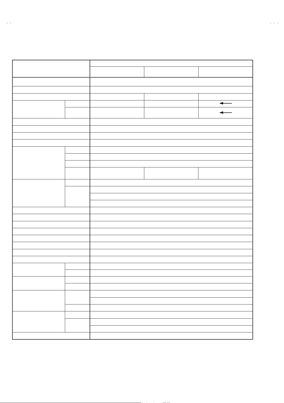
SPECIFICATIONS
Content
ITEM
Dimensions (WxHxD) 78.4 × 58.2 × 49.3 cm
Mass 46.2 kg
TV RF System B/G B/G, L B/G, D/K, K1
TV Mode PAL PAL / SECAM
Colour System
Teletext System Fastext / Toptext
Stereo System German + NICAM
Tuning System Frequenc y Synthesizer Tuning System
Number Of C H memory position 200 ch
Receiving Frequency
Intermediate Frequency
Colour Sub Carrier Frequency PAL (4.43MHz), SECAM (4.43MHz), NTSC (3.58MHz/4.43MHz)
Aerial Input Terminal 75 Ohm Unbalanced
Power Input AC 220 ~ 240V, 50Hz
Power Consumption 135W(Max.) <4W(Stand- by)
Picture Tube 68cm measured diagonally
High Voltage 28.55kV (in cut-off servic e mode)
Speaker ( 77 ×128 mm Oval type + Tweeter ) ×2
Audio Output 12W + 12W
Input
Output
Input Terminal
Remote Control Unit VE-30015781 (RM-C85) , Battery size:AAA/R03 x 2
Video Mode
VHF (VL) 46.25MHZ ~ 168.25MH z
VHF (VH) 175.25MHz ~ 463.25MHz
UHF 471.25MHz ~ 863.25MHz
CATV B/G : S1-S41 & S75-S79
VIF Carrier 38.9MHz
SIF Carrier
Video 1V(p-p), 75 Ohm
Audio (L/R) 500 mV(rms), H igh Impedance
Video 1 V(p-p), 75 O hm
Audio (L/R) 500 mV(rms), Low Impedanc e
Rear Side
Front Side AV 3 (Video/Audio)
Front Side
Rear Side
AV-29BH11ENS AV-29BH11EPS AV-29BH11EES
PAL / NTSC 3.58 /
NTSC 4.43
32.4MHz (6.5MHz)
32.9MHz (6.0MHz)
33.4MHz (5.5MHz)
AV 1 (Video/Audio/RGB)
AV 2 (Video/Audio/S-VHS)
Headphone jack (Stereo mini jack 3.5∅)
AV 1 (Video/Audio)Output Terminal
AV 2 (Video/Audio) (Selected TV, AV1 or AV3)
PAL / SECAM / NTSC 3.58 /
NTSC 4.43
B/G : S1-S41 & S75-S79
L : S1-S41&S75-S77
B/G : S1-S41 & S75-S79
D/K : S1-S41
Design & specifications are subject to change without notice.
2
No.52085
Page 3
A
A
A
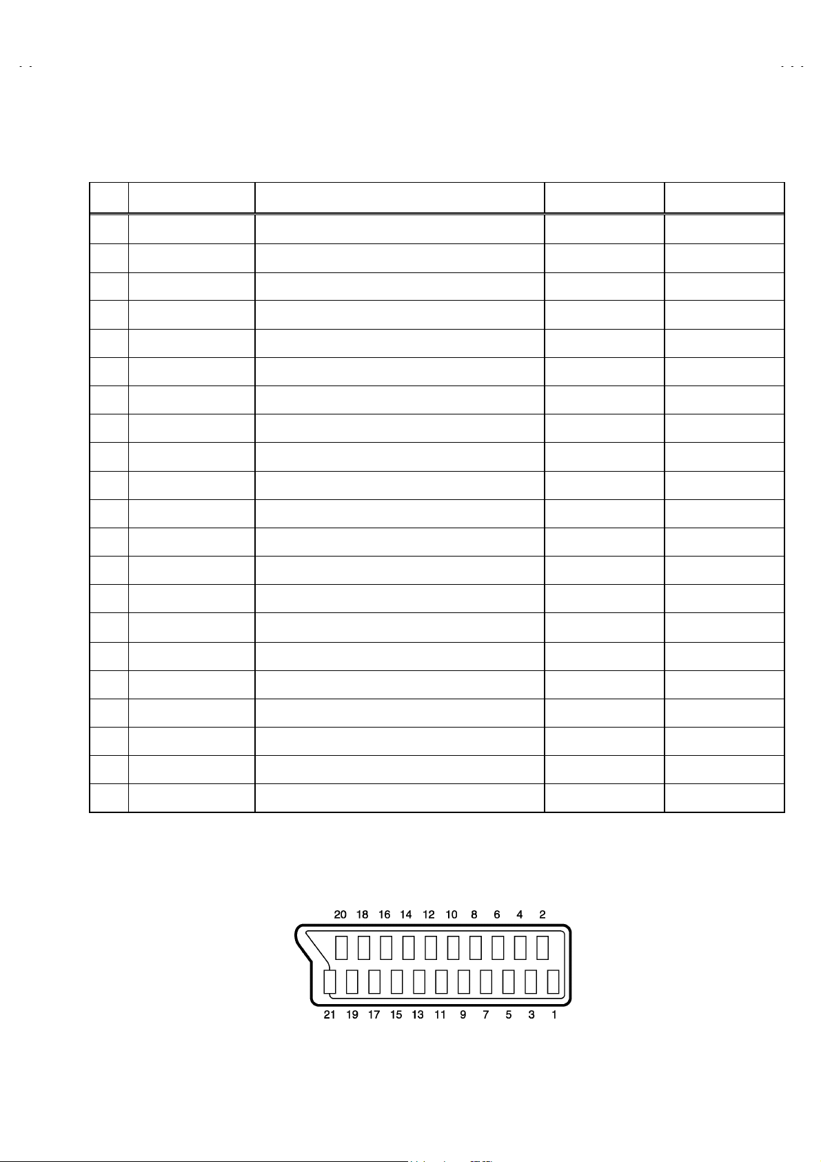
■■■■21-pin Euro connector (SCART socket) : AV 1 / AV 2
(P-P= Peak to Peak, S-W= Sync tip to white peak, B-W= Blanking to white peak)
Pin
No.
Signal Designation Matching Value AV 1 AV 2
1 AUDIO R output 500mV(r ms) (N ominal),Low impedanc e
2 AUDIO R input 500mV(r ms) (Nominal),High impedanc e
3 AUDIO L output 500mV(rms) (Nominal),Low impedance
4 AUDIO GND
V-29BH11ENS
V-29BH11EPS
V-29BH11EES
○
(TV OUT)
○○
○
(TV OUT)
○○
○
(TV/LINE OUT)
○
(TV/LINE OUT)
5 GND (B)
6 AUDIO L input 500mV(rms) (Nominal), High impedance
B-W, 75Ω○
7B input
FUNCTON SW
8
(SLOW SW)
9 GND (G)
10 - NC -
11 G input
12 - NC -
13 GND (R)
14 GND (YS)
15 R / C input
16 Ys input
17 GND(VIDEO output)
18 GND(VIDEO input)
19 VIDEO output
20 VIDEO / Y input
700mV
Low : 0-3V, High : 8-12V, High impedance
B-W
700mV
R : 700mV
C : 300mV (
Low : 0 – 0.4, High : 1 - 3V, 75Ω○
1V
1V
, 75Ω○
B-W, 75Ω
P-P)
, 75Ω
S-W
(Negative going sync), 75Ω
S-W
(Negative going sync), 75Ω○○
○○
○○
○
○○
○○
○
○
(R/C)
○○
○○
○
(TV)
(only C)
(TV/LINE OUT)
NC
NC
NC
NC
○
NC
○
21 COMMON GND
[
Pin assignment
]
No.52085
○○
3
Page 4
A
V-29BH11ENS
A
A
V-29BH11EPS
V-29BH11EES
SAFETY PRECAUTIONS
1. The design of this product cont ains special hardware, many
circuits and components specially for safety purposes. For
continued protection, no changes should be made to the original
design unless authorized in writing by the manufacturer.
Replacement parts must be identic al to those used in the original
circuits. Service should be performed by qualified personnel
only.
2. Alterations of the design or circuitry of the products should not be
made. Any design alterations or additions will void the
manufacturer's warranty and will further relieve the manufacturer
of responsibility for personal injur y or property damage resulting
theref rom.
3. Many electric al and mechanical parts in the products have
special safety-related characteristics. These characteristics are
often not evident from visual inspection nor c an the protection
afforded by them necessarily be obtained by using replacement
components rated for higher voltage, wattage, etc. Replacement
parts which have these special safety characteristics are
identified in the parts list of Service manual. Electrical
components having such features are identified by shading
on the schematics and by (!!!!) on the parts list in Service
manual. The use of a substitute replacement which does not
have the s ame safety characteristics as the recommended
replacement part shown in the parts list of Service manual may
cause shock, fire, or other hazards.
4. Don't short between the LIVE side ground and ISOLATED
(NEUTRAL) side ground or EARTH side ground when
repairing.
Some model's power circuit is partly different in the GND. The
differenc e of the GND is shown by the LIVE side GND , the
ISOLATED(NEUTRAL) side GND and EARTH side GND. Don't
short between the LIVE side GND and ISOLATED(NEUT RAL)
side GND or EARTH side GND and never measure with a
measuring apparatus (oscillosc ope etc.) the LIVE side GND and
ISOLATED(NEUTRAL) side GND or EARTH side GND at the
same time.
If above note will not be kept, a fuse or any parts will be broken.
5. If any repair has been made to the chassis, it is recommended
that the B1 setting should be checked or adjusted (See
ADJUSTMENT OF B1 POWER SUPPLY).
6. The high voltage applied to the picture tube must conform with
that specified in Service manual. Excessive high voltage can
cause an incr ease in X-Ray emission, arcing and possible
component damage, therefore operation under excessive high
voltage conditions should be kept to a minimum, or should be
prevented. If severe arcing occurs, remove the AC power
immediately and det ermine the caus e by visual inspection
(incorrect installation, cr acked or melted high voltage harness,
poor soldering, etc.). To maintain the proper minimum level of
soft X-Ray emission, components in the high voltage circuitry
including the picture tube must be the exact replacements or
alternatives approved by the manuf acturer of the complete
product.
7. Do not check high voltage by drawing an arc. Use a high voltage
meter or a high voltage probe with a VTVM. Discharge the
picture tube before attempting meter connection, by connecting
a clip lead to the ground frame and connecting the other end of
the lead through a 10kΩ 2W resistor to the anode button.
8. When service is required, obser ve the original lead dress. Extra
precaution should be given to assure correct lead dress in the
high voltage circuit area. W here a short circuit has occurr ed,
those components that indicate evidenc e of overheating should
be replaced. Always us e the manufactur er's replacement
components.
9. Isolation Check
(Safety for Electrical Shock Hazard)
After re-assembling the product, always perf orm an isolation
check on the exposed metal parts of the cabinet (antenna
terminals, video/audio input and output terminals, Control knobs,
metal c abinet, screwheads, earphone jack, c ontrol shafts, etc.)
to be sure the product is safe to operate without danger of
electr ic al sh oc k.
(1) Dielectr ic Strength Test
The isolation between the AC primary circuit and all metal parts
exposed to the user, particularly any expos ed metal part having a
return path to the chassis should withstand a voltage of 3000V
AC (r.m.s.) for a period of one second.
(. . . . Withstand a voltage of 1100V AC (r.m.s.) to an applianc e
rated up to 120V, and 3000V AC (r.m.s.) to an appliance rated
200V or more, for a period of one second.)
This method of test requires a test equipment not gener ally found
in the s ervice trade.
(2) Leakage Current Check
Plug the AC line cord directly into the AC outlet (do not use a line
isolation transformer dur ing this check.). Using a " Leakage
Current T ester", measure the leakage current from each exposed
metal part of the cabinet, particularly any exposed metal part
having a return path to the chassis, to a known good earth
ground (water pipe, etc.). Any leakage c urrent must not exceed
0.5mA AC (r.m.s.).
However, in tr opical area, this must not exceed 0.2mA AC
(r.m.s.).
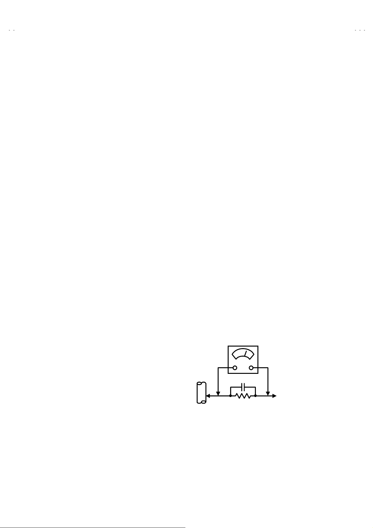
"""" Alternate Check Method
Plug the AC line cord directly into the AC outlet (do not use a line
isolation transformer during this check.). Use an AC voltmeter
having 1000 ohms per volt or more sensitivity in the following
manner. Connect a 1500Ω 10W resistor paralleled by a 0.15µF
AC-type capacitor between an expos ed metal part and a known
good earth ground (water pipe, etc.). Measure the AC voltage
across the resistor with the AC voltmeter. Move the resistor
connection to each exposed metal part, particularly any exposed
metal part having a return path to the chassis, and measure the
AC voltage across the resistor. Now, reverse the plug in the AC
outlet and repeat each measurement. Any voltage meas ured
must not exceed 0.75V AC (r.m.s.). This corresponds to 0.5mA
AC (r.m.s.).
However, in tr opical area, this must not exc eed 0.3V AC (r.m.s.).
This corresponds to 0.2mA AC (r.m.s.).
AC VOLTMETER
(HAVING 1000 Ω/V,
OR MORE SENSITIVITY)
0.15μF AC-TYPE
PLACE THIS PROBE
1500 Ω 10W
GOOD EARTH GROUND
ON EACH EXPOSED
METAL PART
4
No.52085
Page 5
A
A
A
FEATURES
V-29BH11ENS
V-29BH11EPS
V-29BH11EES
1. It is a remote c ontrolled color television.
2. 200 programs from VHF, UHF bands or cable channels can be
preset.
3. It can tune cable channels.
4. Controlling the TV is very easy by its menu driven s ystem.
5. It has two Euroconnector s ockets f or external device (such as
video recorder, video games, audio set, etc.)
6. Front AV Input available.
7. Stereo s ound systems (German + Nic am) are available.
8. Full function T eletext (Fastext, Toptext).
9. It is possible to connect headphone.
10. Direct channel access.
11. APS (Automatic Programming System).
12. All programs can be named.
13. Forward or backward automatic tuning.
14. Automatic sound mute when no transmission.
15. 5 minutes after the broadcasting (closedown), the T V switches
itself automatically to stand-by mode.
MAIN DIFFERENCE LIST
MODEL No.
Parts Name
MAIN PWB VE-20101060 VE-20101082 VE-20101061
LABEL
AV-29BH11ENS AV-29BH11EPS AV-29BH11EES
VE-20102005
VE-20101990 (Only ITA)
VE-20101971
VE-20101987
VE-20101985 (Only POL)
F CARTON BOX
INST BOOK VE-50028435 VE-50028433 VE-50028434
VE-50028449
VE-50028445 (Only ITA)
VE-50028438
VE-50028443
VE-50028442 (Only POL)
No.52085
5
Page 6

A
V-29BH11ENS
A
A
V-29BH11EPS
V-29BH11EES
SPECIFIC SERVICE INSTRUCTIONS
DISASSEMBLY PROCEDURE
REMOVING THE REAR COVER
1. Remove the 8 screws marked A.
2. Remove the 4 screws marked B.
3. W ithdraw the rear c over toward you.
REMOVING THE MAIN PWB
" Removing the rear cover.
1. Slightly raise the both sides of the chassis by hand and withdraw
MAIN PWB back ward.
[CAUTIONS]
If necessary, take off the wire clamp, connectors etc.
Be careful enough when developing a main chassis.
REMOVING THE FRONT AV & HEADPHONE
BOARD ASS’Y
" Removing the rear cover.
" Removing the MAIN PWB.
1. Remove the 2 screws marked C, and remove the FRONT AV &
HEADPHONE BOARD ASS’Y.
REMOVING THE FRONT CONTROL PWB
"
Removing the rear cover.
" Removing the MAIN PWB.
1. Remove the 3 screws marked D, and remove the FRONT
CONTROL PWB.
CHECKING THE PW BOARD
To check the back side of the PW Board.
1) Pull out the PW Board. (Refer to REMOVING THE MAIN
PWB).
2) Erect the PW Board vertically so that you can easily check
the back side of the PW Board.
[CAUTION]
" When er ecting the PW Board, be careful so that there will be no
contac ting with other PW Boar d.
" Before turning on power, make sure that the wire connector is
properly connected.
" When conducting a check with power supplied, be sure to confirm
that the CRT EARTH WIRE (BRAIDED ASS’Y) is connected to
the CRT SOCKET PW board.
WIRE CLAMPING AND CABLE TYING
1. Be sure t o clamp the wire.
2. Never remove the cable tie us ed for tying the wires together.
Should it be inadvertently removed, be sure to tie the wires with
a new cable tie.
REMOVING THE WOOFER and TWEETER
" Removing the rear cover.
1. Remove the 4 screws marked E, and remove the WOOFER.
2. Remove the 2 screws marked F, and remove the TW EETER.
3. Remove an opposite side similarly.
REMOVING THE MAIN SWITCH
" Removing the rear cover.
" Removing MAIN PW B.
1. Remove the 2 screws marked G, and remove the MAIN
SWITCH.
6
No.52085
Page 7

A
A
A
A
(×8)
V-29BH11ENS
V-29BH11EPS
V-29BH11EES
STEREO
MODULE PWB
B
(×4)
FEAT URE BOX
PWB
MAIN PWB
REAR COVER
FRONT CABINET
E
(×4)
F
(×2)
E
(×4)
SPEAKER
(WOOFER)
F
(×2)
SPEAKER
(TWEETER)
D
(×3)
FRONT CONTROL
PWB
No.52085
G
(×2)
MAIN
SWITCH
C
(×2)
FRONT AV &
HEADPHONE
PWB
7
Page 8

A
V-29BH11ENS
A
A
V-29BH11EPS
V-29BH11EES
SETTING OF THE LAST MEMORY FOR SHIPMENT
■■■■ USER SETTING VALUES
Setting Item Setting Value Setting Item Setting Value
SOUND MENU FEATURE MENU
BASS CENTER SLEEP TIMER OFF
TREBLE
BALANCE
EFFECT OFF
PICTURE MENU INSTALL
BRIGHTNESS LANGUAGE ENGLISH
COLOUR COUNTRY Other
CONTRAST AV-2 OUTPUT TV
SHARPNESS
HUE (only NTSC)
These adjust are automatically
restored when APS bit in Service
menu is s et.
The proc edure f or setting APS
bit is described bellow.
↑
↑
CHILD LOCK OFF
■ SETTING APS BIT IN SERVICE MENU
1) Enter service menu in TV mode by pressing “INFO ” and “MUTING” keys simultaneously. Service Menu will appear.
2) Select VIDEO by pressing “GREEN” key on the remote control unit.
3) Select APS items by pressing the Up/Down keys on the remote control unit.
4) Change the value to “ON” by pressing LEFT/RIGHT keys on the remote contr ol unit.
5) Store the change by pressing “IN FO” key.
6) Press “STANDARD” key on remot e control unit to exit servic e mode.
8
No. 52085
Page 9

A
A
A
SERVICE ADJUSTMENTS
ADJUSTMENT PREPARATION
1. You can make the necessary adjustments for this unit with
either the Remote Control Unit or with the adjustment tools
and parts as given belo w.
2. Adjustment with the Remote Control Unit is made on the
basis of the initial setting values, however, the new setting
values which set the screen to its optimum condition may
differ from the initial settings.
3. Make sure that AC power is turned on correctly.
4. Turn on the power for set and test equipment before use, and
start the adjustment procedures after waiting at least 30 minutes.
5. Unless otherwise specified, prepare the most suitable reception
or input signal for adjustment.
6. Never touch any adjustment parts which are not specified in the
list for this adjustment - variable resistors, transformers,
condensers, etc.
7. Presetting before adjustment.
Unless otherwise specified in the adjustment instructions, pr eset
the following functions with the remote control unit:
TINT / COLOUR
PICTURE/BRIGHT
V-29BH11ENS
V-29BH11EPS
V-29BH11EES
CENTER
ADJUSTMENT EQUIPMENT
1. DC voltmeter (or digital voltmeter)
2. Signal generator (Pattern generator)[PAL/SECAM/NTSC]
3. Remote c ontrol unit
MAIN PARTS LOCATIONS
FRONT AV & HEADPHONE PWB
FRONT
VIDEO
HEADPHONE JACK
RL
AUDIO
IC304
MICOM
LED
IC302
MEMOR Y IC
FEAT URE BOX PWB
REMOCON
RECEIVER
FRONT CONTROL PWB
MENU
(+)
(+) (-)
(-)
(+)(+)
(-)(-)
PROG
/Ch.
MAIN PWB
(+)
(+) (-)
(-)
(+)(+)
(-)(-)
VOL
TOP
FRONT
FBT
STEREO MODULE PWB
TUNER
No. 52085
UPPER : FOCUS VR
LOWER : SCREEN VR
9
Page 10

A
V-29BH11ENS
A
A
A
A
V-29BH11EPS
V-29BH11EES
BASIC OPERATION SERVICE MENU
■■■■ HOW TO ENTER THE SERVICE MODE
1) Press the INFORMATION key and MUTING key of
REMOTE CONTROL UNIT simultaneously, and the
SERVICE MENU screen of Fig.1 will be displayed.
REMOTE CONTROL UNIT key NAME
SERVICE MENU (1/2)
PRODUCTION i >STORE MENU >E XIT
H/V
V-SHIFT 000
V-SIZE 0038
H-SHIFT 1224
H-SIZE 023
S-COR 027
LINRT -07
ANGLE 003
BOW 002
TRAPEZ -07
PARAB -39
U.COR -01
L.COR 002
TILT 000
TRPZD 018
K41 G035
18. 12. 2001
VIDEO
WdR 079
WdG 064
WdB 067
CuR 064
CuG 064
CuB 064
YDP -04
AGC 045
APSW 2
APS ON
T_T THO
T_P SAM
YDS -06
YDN -01
DVD OFF
C.M OFF
BLUE ON
SERVICE
Fig.1
2) While the Fig.1 is displayed, press the BLUE key for
access to the SERVICE MENU (2/2) (Fig.2).
SERVICE MENU (2/2)
PRODUCTION i >STORE MENU >E XIT
DJUSTMENTS
PIP CNTRST 000
PIP YDelay 000
PIP Frame 0
EHTHP 001
EHTH TC 0 00
EHTH -36
EHTV -14
EHTV TC 005
SVDEL 000
BCLTHRES T1
OSD CONT 080
OSD BRI 035
TEXT BRI 030
INIT NVM
Prescaler
FM 015
NICAM 035
I2S 016
SCART 025
OPTIONS
0.HPHONE OFF
1.CRT 4:3
2.S-VHS OFF
3.f(IF) 38.9
4.Turk ON
5.VGA OFF
6.FRONT ON
7.DPL OFF
8.VD OFF
9.NSL ON
SYSTEM
0.PAL B/G ON
1.PAL D/K OFF
2.PAL I OFF
3.SECAM B/G ON
4.SECAM D/K OFF
5.SECAM L/L’ ON
6.AUST. OFF
MUTING key
GREEN key
RED key
UP / DOWN
(
) key
/
INFORMATION
key
YELLOW key
BLUE key
COLOUR key
MENU key
LEFT / RIGHT
(
) key
/
Fig.2
HOW TO EXIT SERVICE MODE
■
1) Pr ess the MENU Key on REMOTE CONTROL UNIT.
10
No. 52085
Page 11

A
A
A
■■■■ SELECTION OF ADJUSTMENT ITEMS
A
A
1) Press the COLOUR key and select the service menu section.
2) Select the ADJUST Item, use UP ( ) / DOWN( ) key of
remote c ontrol unit.
3) To change the selected parameter, use LEFT ( ) and
RIGHT ( ) key.
4) Press the INFORMATION key to STORE.
PRODUCTION i >STORE MENU >E XIT
H/V
V-SHIFT 000
V-SIZE 0038
H-SHIFT 1224
H-SIZE 023
RED key
select H/V
S-COR 027
LINRT -07
ANGLE 003
BOW 002
TRAPEZ -07
PARAB -39
U.COR -01
L.COR 002
TILT 000
TRPZD 018
K41 G035
18. 12. 2001
SERVICE MENU (1/2)
VIDEO
WdR 079
WdG 064
WdB 067
CuR 064
CuG 064
CuB 064
YDP -04
AGC 045
APSW 2
APS ON
T_T TH O
T_P SAM
YDS -06
YDN -01
DVD OFF
C.M OFF
BLUE ON
SERVICE
V-29BH11ENS
V-29BH11EPS
V-29BH11EES
GREEN key
select VIDEO
BLUE key
acc ess SERVICE
(SERVICE MENU 2/2)
Do Not Adjust
PRODUCTION i >STORE MENU >E XIT
DJUSTMENTS
PIP CNTRST 000
PIP YDelay 000
PIP Frame 0
EHTHP 001
RED key
select ADJUSTMENTS
GREEN key
select Prescaler
EHTH TC 0 00
EHTH -36
EHTV -14
EHTV TC 005
SVDEL 000
BCLTHRES T1
OSD CONT 080
OSD BRI 035
TEXT BRI 030
INIT NVM
Prescaler
FM 015
NICAM 035
I2S 01 6
SCART 025
SERVICE MENU (2/2)
OPTIONS
0.HPHONE OFF
1.CRT 4:3
2.S-VHS OFF
3.f(IF) 38.9
4.Turk ON
5.VGA OFF
6.FRONT ON
7.DPL OFF
8.VD OFF
9.NSL ON
SYSTEM
0.PAL B/G ON
1.PAL D/K OFF
2.PAL I OFF
3.SECAM B/G ON
4.SECAM D/K OFF
5.SECAM L/L’ ON
6.AUST. OFF
BLUE key
select OPTIONS
YELLOW key
select SYSTEM
No. 52085
11
Page 12

A
V-29BH11ENS
A
A
V-29BH11EPS
V-29BH11EES
ADJUSTMENTS
■■■■ DEFLECTION CIRCUIT
Item
V-SHIFT
adjustment
Measurin g
instrument
Signal
generator
Remote
control unit
Test point Adjustment part Description
V- SHIFT 1. Receive a circle pattern signal of vertic al frequency 50Hz.
2. Enter the SERVICE MENU.
3. Press the RED key on the remote control unit, then enter the
H/V adjustment group.
4. Select V-SHIFT with the UP/DOW N ( / ) key.
5. Adjust V-SHIFT with the LEFT/RIGHT ( / ) key to make
A = B.
6. Check and r eadjust V-SHIFT item if the adjustment becomes
improper after some other geometric adjustments are done.
7. Press the INFORMATION key and memorize the set value.
A
B
V-SIZE
adjustment
very close
Screen
size
very close
Signal
generator
Remote
control unit
V-SIZE 1. Receive a cross-hatch signal.
2. Enter the SERVICE MENU.
3. Press the RED key on the remote control unit, then enter the
H/V adjustment group.
4. Select V-SIZE with the UP/DOW N ( / ) key.
5. Adjust V-SIZE with the LEFT/RIGHT ( / ) key until
horizontal black lines on both the upper and lower part of the
cross-hatch pattern become very close to the upper and lower
horizontal sides of picture size and nearly about to disappear.
6. Check and readjust V-SIZE it em if the adjustment becomes
improper after some other geometric adjustments are done.
7. Press the INFORMATION key and memorize the set value.
Picture
size
100%
12
No. 52085
Page 13

A
V-29BH11ENS
A
A
V-29BH11EPS
V-29BH11EES
Item
H-SHIFT
adjustment
Measurin g
instruments
Signal
generator
Remote
control unit
CD
Test point Adjustment part Description
H-SHIFT 1. Receive a circle pattern signal.
2. Enter the SERVICE MENU.
3. Press the RED key on the remote control unit, then enter the
H/V adjustment group.
4. Select H-SH IFT with the UP/DOW N ( / ) key.
5. Adjust H-SHIFT with the LEFT/RIGHT ( / ) key to make
C= D.
6. Check and readjust H-SHIFT item if the adjustment
becomes improper after some other geometric adjustments
are done.
7. Press the INFORMATION key and memorize the set value.
H-SIZE
adjustment
very
close
Signal
generator
Remote
control unit
Picture size 100%
Screen size
H-SIZE 1. Receive a cross-hatch signal.
2. Enter the SERVICE MENU.
3. Press the RED key on the remote control unit, then enter the
H/V adjustment group.
4. Select H-SIZE with the UP/DOW N ( / ) key.
5. Adjust H-SIZE with the LEFT/RIGHT ( / ) key till vertical
lines on both the left and right part of the cross-hatch will be
visible nor scr een will be so wide.
6. Check and readjust H-SIZE item if the adjustment becomes
improper after some other geometric adjustments are done.
very
close
7. Press the INFORMATION key and memorize the set value.
No. 52085
13
Page 14

A
V-29BH11ENS
A
A
V-29BH11EPS
V-29BH11EES
Item
V.
S-CORRECT.
& LINEARITY
adjustment
Measurin g
instruments
Signal
generator
Remote
control unit
Test point Adjustment part Description
S-COR
LINRT
UPPER
CENTER
LOWER
1. Receive a cross-hatch signal.
2. Enter the SERVICE MENU.
3. Press the RED key on the remote control unit, then enter the
H/V adjustment group.
4. Select S-COR with the UP/DOWN ( / ) key.
5. Adjust S-COR with the LEFT/RIGHT ( / ) key till the size
of squares on both the upper and lower part of cross-hatch
pattern become equal to the square laying on the vertic al
center of the cross-hatch pattern.
6. Check and readjust S-COR item if the adjustment becomes
improper after some other geometric adjustments are done.
7. Press the INFORMATION key and memorize the set value.
8. Select LINRT with the UP/DOWN ( / ) key.
9. Adjust LINRT with the LEFT/RIGHT ( / ) key till all the
size of squares of the cross-hatch pattern become in equal
size from the top of the screen to its bottom of the whole
screen.
10. Check and readjust LINRT item if the adjustment bec omes
improper after some other geometric adjustments
(especially after than S-COR adjustment) are done.
11. Press the INFORMATION key and memorize the set value.
ANGLE
adjustment
Signal
generator
Remote
control unit
ANGLE
1. Receive a cross-hatch signal.
2. Enter the SERVICE MENU.
3. Press the RED key on the remote control unit, then enter the
H/V adjustment group.
4. Select ANGLE with the UP/DOWN ( / ) key.
5. Adjust ANG LE with the LEFT/RIGHT ( / ) key till the
vertical lines of the crosshatch pattern become straight.
6. Check and readjust ANGLE item if the adjustment becomes
improper after some other geometric adjustments are done.
7. Press the INFORMATION key and memorize the set value.
14
No. 52085
Page 15

A
V-29BH11ENS
A
A
V-29BH11EPS
V-29BH11EES
Item
BOW
adjustment
Measurin g
instruments
Signal
generator
Remote
control unit
Test point Adjustment part Description
BOW
1. Receive a cross-hatch signal.
2. Enter the SERVICE MENU.
3. Press the RED key on the remote control unit, then enter the
H/V adjustment group.
4. Select BOW with the UP/DOWN ( / ) key.
5. Adjust BOW with the LEFT/RIGHT ( / ) key and the
vertical line straight.
6. Check and readjust BOW item if the adjustment becomes
improper after some other geometric adjustments are done.
7. Press the INFORMATION key and memorize the set value.
NOTE :
In case where there is a bow-shaped distortion of images on
the screen. (Figure)
TRAPEZIUM
adjustment
Signal
generator
Remote
control unit
Parallel
TRAPEZ 1. Receive a cross-hatch signal.
2. Enter the SERVICE MENU.
3. Press the RED key on the remote control unit, then enter the
H/V adjustment group.
4. Select TRAPEZ with the UP/DOW N ( / ) key.
5. Adjust TRAPEZ with the LEFT/RIGHT ( / ) key till vertical
lines, especially lines at the sides of the picture frame
became par allel to the both sides of picture tube as close as
possible.
6. Check and readjust TRPEZ item if the adjustment becomes
improper after some other geometric adjustments are done.
7. Press the INFORMATION key and memorize the set value.
No. 52085
15
Page 16

A
V-29BH11ENS
A
A
V-29BH11EPS
V-29BH11EES
Item
SIDE PIN
adjustment
Measurin g
instrument
Signal
generator
Remote
control unit
Test point Adjustment part Description
PARAB 1. Receive a cross-hatch signal.
2. Enter the SERVICE MENU.
3. Press the RED key on the remote control unit, then enter
the H/V adjustment group.
4. Select PARAB with the UP/DOWN ( / ) key.
5. Adjust PARAB with the LEFT/RIGHT ( / ) key till vertical
lines close to the both sides of the picture frame become
parallel to vertical sides of picture tube without any bending
Parallel
to left or to right side of the screen.
6. Check and readjust PARAB item if the adjustment becomes
improper after some other geometric adjustments are done.
7. Press the INFORMATION key and memorize the set value.
CORNER
adjustment
Signal
generator
Remote
control unit
Straight Straight
U.COR
L.COR
1. Receive a cross-hatch signal.
2. Enter the SERVICE MENU.
3. Press the RED key on the remote control unit, then enter
the H/V adjustment group.
4. Select U.COR with the UP/DOWN ( / ) key.
5. Adjust U.COR with the LEFT/RIGHT ( / ) key till vertical
lines at the upper corners of the pictur e frame become
vertical and parallel to vertical corner sides of picture tube.
6. Check and readjust U.COR item if the adjustment becomes
improper after some other geometric adjustments are done.
7. Press the INFORMATION key and memorize the set value.
8. Select L.COR with the UP/DOWN ( / ) key.
9. Adjust L.COR with the LEFT/RIGHT ( / ) key till vertical
lines at the lower c orners of the picture f rame become
vertical and parallel to vertical corner sides of picture tube.
10. Check and readjust L.COR item if the adjustment becomes
improper after some other geometric adjustments are done.
11. Press the INFORMATION key and memorize the set value.
16
No. 52085
Page 17

A
A
A
■■■■ VIDEO CIRCUIT
V-29BH11ENS
V-29BH11EPS
V-29BH11EES
Item
WHITE
BALANCE
adjustment
COLOUR
CUTOFF
LEVEL
adjustment
Measurin g
instrument
Signal
generator
Remote
control unit
Signal
generator
Remote
control unit
Test point Adjustment part Description
WdR
WdG
WdB
CuR
CuG
CuB
1. Receive a black & white signal.
2. Enter the SERVICE MENU.
3. Press the GREEN key on the r emote control unit, then enter
the VIDEO adjustment gr oup.
4. Select W dR, WdG and WdB with the UP/DOWN ( / ) key
respectively.
5. Adjust W dR, W dG and WdB with the LEFT/RIGHT ( / ) key
respectively, until the white part turns to pure white without
any other colour.
6. Press the INFORMATION key and memorize the set value.
1. Receive a cross-hatch signal.
2. Enter the SERVICE MENU.
3. Press the GREEN key on the r emote control unit, then enter
the VIDEO adjustment gr oup.
4. Select CuR, CuG and CuB with the UP/DOWN ( / ) key
respectively.
5. Adjust CuR, CuG and CuB with the LEFT/RIGHT ( / ) key
respectively and set the values of these items as 64
(constant).
6. Press the INFORMATION key and memorize the set value.
PAL
Y DELAY
adjustment
AGC
adjustment
Signal
generator
Remote
control unit
Signal
generator
Remote
control unit
YDP 1. Receive a PAL COLOUR BAR signal.
2. Enter the SERVICE MENU.
3. Press the GREEN key on the r emote control unit, then enter
the VIDEO adjustment gr oup.
4. Select YDP with the UP/DOWN ( / ) key.
5. Adjust YDP by pressing with the LEFT/RIGHT ( / ) key till
the colour transients on the colour bar pattern becomes as
sharper and possible as colours between transients do not
mix with each other.
6. Press the INFORMATION key and memorize the set value.
AGC
1. Receive a PAL BG signal at 60dBμV RF signal level.
2. Enter the SERVICE MENU.
3. Press the GREEN key on the r emote control unit, then enter
the VIDEO adjustment gr oup.
4. Select AGC with the UP/DOW N ( / ) key.
5. Adjust AGC by pressing with the LEFT/RIGHT ( / ) key till
voltage at pin9 of PL202 is equal to 3.0V
6. Press the INFORMATION key and memorize the set value.
No. 52085
17
Page 18

A
V-29BH11ENS
A
A
V-29BH11EPS
V-29BH11EES
Item
SECAM
Y DELAY
adjustment
NTSC
Y DELAY
adjustment
Measurin g
instrument
Signal
generator
Remote
control unit
Signal
generator
Remote
control unit
Test point Adjustment part Description
YDS 1. Receive a SECA M COLOUR BAR signal.
2. Enter the SERVICE MENU.
3. Press the GREEN key on the r emote control unit, then enter
the VIDEO adjustment gr oup.
4. Select YDS with the UP/DOWN ( / ) key.
5. Adjust YDS by pressing with the LEFT/RIGHT ( / ) key till
the colour transients on the colour bar pattern becomes as
sharper and possible as colours between transients do not
mix with each other.
6. Press the INFORMATION key and memorize the set value.
YDN 1. Receive a NTSC COLOUR BAR signal from an external
source (e.g. AV 1).
2. Enter the SERVICE MENU.
3. Press the GREEN key on the r emote control unit, then enter
the VIDEO adjustment gr oup.
4. Select YDN with the UP/DOWN ( / ) key.
5. Adjust YDN by pressing with the LEFT/RIGHT ( / ) key till
the colour transients on the colour bar pattern becomes as
sharper and possible as colours between transients do not
mix with each other.
6. Press the INFORMATION key and memorize the set value.
18
No. 52085
 Loading...