

Page 1

SERVICE MANUAL
COLOUR TELEVISION
AV-29BF11ENS
AV-29BF11EPS
AV-29BF11ENS AV-29BF11EPS AV-29BF11EES
CONTENTS
AV-29BF11EES
SPECIFICATIONS ・・・・・・・・・・・・・・・・・・・・・・・・・・・・・・・・
!
SAFETY PRECAUTIONS ・・・・・・・・・・・・・・・・・・・・・・・・・・・・・・・・
!
FEATURES・・・・・・・・・・・・・・・・・・・・・・・・・・・・・・・・
!
MAIN DIFFERENCE LIST ・・・・・・・・・・・・・・・・・・・・・・・・・・・・・・・・
!
SPECIFIC SERVICE INSTRUCTIONS ・・・・・・・・・・・・・・・・・・・・・・・・・・・・・・・・
!
SERVICE ADJUSTMENTS ・・・・・・・・・・・・・・・・・・・・・・・・・・・・・・・・
!
PARTS LIST ・・・・・・・・・・・・・・・・・・・・・・・・・・・・・・・・
!
★ OPERATING INSTRUCTIONS
★ STANDARD CIRCUIT DIAGRAM ・・・・・・・・・・・・・・・・・・・・・・・・・・・・・・・・
1
・・・・・・・・・・・・・・・・・・・・・・・・・・・・・・・・・・・・・・・・・・・・・・・・・・・・・・・・・・・・・・・・
・・・・・・・・・・・・・・・・・・・・・・・・・・・・・・・・・・・・・・・・・・・・・・・・・・・・・・・・・・・・・・・・
・・・・・・・・・・・・・・・・・・・・・・・・・・・・・・・・・・・・・・・・・・・・・・・・・・・・・・・・・・・・・
・・・・・・・・・・・・・・・・・・・・・・・・・・・・・・・・・・・・・・・・・・・・・・・・・・・・・・・・・・・・・・・・
・・・・・・・・・・・・・・・・・・・・・・・・・・・・・・・・・・・・・・・・・・・・・・・・・・・・・・・
・・・・・・・・・・・・・・・・・・・・・・・・・・・・・・・・・・・・・・・・・・・・・・・・・・・・・・・・・・・・・・・・
・・・・・・・・・・・・・・・・・・・・・・・・・・・・・・・・・・・
・・・・・・・・・・・・・・・・・・・・・・・・・・・・・・・・・・・・・・・・・・・・・・・・・・・・・・・・・・・・・・・・
・・・・・・・・・・・・・・・・・・・・・・・・・・・・・・・・・・・・・・・・・・・・・・・・・・・・・・・
・・・・・・・・・・・・・・・・・・・・・・・・・・・・・・・・・・・・・・・・・・・・・・・・・・・・・・・・・・・・・・・・
・・・・・・・・・・・・・・・・・・・・・・・・・・・・・・・・・・・・・・・・・・・・・
・・・・・・・・・・・・・・・・・・・・・・・・・・・・・・・・・・・・・・・・・・・・・・・・・・・・・・・・・・・・・・・・
・・・・・・・・・・・・・・・・・・・・・・・・・・・・・・・・・・・・・・・・・・・・・・・・・・・・・
・・・・・・・・・・・・・・・・・・・・・・・・・・・・・・・・・・・・・・・・・・・・・・・・・・・・・・・・・・・・・・・・
・・・・・・・・・・・・・・・・・・・・・・・・・・・・・・・・・・・・・・・・・・・・・・・・・・・・・・・・・・・・・・・・
・・・・・・・・・・・・・・・・・・・・・・・・・・・・・・・・・・・・・・・・・・・・・・・・・・・・・・・・・・・・・・・・
・・・・・・・・・・・・・・・・・・・・・・・・・・・・・・・・・・・・・・・・・・・・・・・・
・・・・・・・・・・・・・・・・・・・・・・・・・・・・・・・・・・・・・・・・・・・・・・・・・・・・・・・・・・・・・・・・
COPYRIGHT © 2002 VICTOR COMPANY OF JAPAN, LTD.
・・・・・・・・・・・・・・・・・・・・・・・・・・・・・ 2
・・・・・・・・・・・・・・・・・・・・・・・・・・・・・・・・・・・・・・・・・・・・・・・・・・・・・・・・・・
・・・・・・・・・・・・・・・・・・・・・・・ 4
・・・・・・・・・・・・・・・・・・・・・・・・・・・・・・・・・・・・・・・・・・・・・・
・・・・・・・・・・・・・・・・・・・・・・・ 5
・・・・・・・・・・・・・・・・・・・・・・・・・・・・・・・・・・・・・・・・・・・・・・
・・・・・・・・・・・・・・・・・・・・・ 11
・・・・・・・・・・・・・・・・・・・・・・・・・・・・・・・・・・・・・・・・・・
・・・・・・・・・・・・・・・・・・・・・・・・・・・・・・・・・・・・ 23
・・・・・・・・・・・・・・・・・・・・・・・・・・・・・・・・・・・・・・・・・・・・・・・・・・・・・・・・・・・・・・・・
・・・ 5
・・・・・・
・・・・・・・・・・・・・ 6
・・・・・・・・・・・・・・・・・・・・・・・・・・
・・・・・・・・・・・・・・・・ 2-1
・・・・・・・・・・・・・・・・・・・・・・・・・・・・・・・・
No.52084
Sep. 2002
Page 2

A
V-29BF11ENS
A
A
V-29BF11EPS
V-29BF11EES
SPECIFICATIONS
ITEM
Dimensions (WxHxD) 78.4 × 58.2 × 49.3 cm
Mass 46.2 kg
TV RF System B/G B/G, L B/G, D/K, K1
Colour System
Teletext System Fastext / Toptext
Stereo System German + NICAM
Tuning System Frequenc y Synthesizer Tuning System
Number of CH memory position 100 ch
Receiving Frequency
Intermediate Frequency
Colour Sub Carrier Frequency PAL (4.43MHz), SECAM (4.43MHz), NTSC (3.58MHz/4.43MHz)
Aerial Input Terminal 75 Ohm Unbalanced
Power Input AC 220 ~ 240V, 50Hz
Power Consumption 135W(Max.) / 120W (Avg.) , <4W(Standby)
Picture Tube Visible size : 68cm Measured diagonally
High Voltage 29.6kV
Speaker ( 77 ×128 mm oval type + Tweeter ) ×2
Audio Output 10W + 10W
Input
Output
Input Terminal
Output Terminal
Remote Control Unit VE-30017763 (RM-C1100) , Battery size:AA/R06 x 2
TV Mode PAL PAL / SECAM
Video Mode
VHF (VL) 46.25MHZ ~ 168.25MH z
VHF (VH) 175.25MHz ~ 463.25MHz
UHF 471.25MHz ~ 863.25MHz
CATV B/G :S01-S41, S75-S79
VIF Carrier 38.9MHz
SIF Carrier
Video 1V(p-p), 75 Ohm
Audio (L/R) 500 mV(rms), H igh Impedance
Video 1 V(p-p), 75 O hm
Audio (L/R) 500 mV(rms), Low Impedanc e
Rear Side
Front Side AV 3 (Video/Audio)
Front Side Headphone jack (Stereo mini jack 3.5φ)
Rear Side
AV-29BF11ENS AV-29BF11EPS AV-29BF11EE S
PAL / NTSC 3.58 /
NTSC 4.43
32.4MHz (6.5MHz : L)
32.9MHz (6.0MHz : D/K)
33.4MHz (5.5MHz : B/G)
AV 1 (Video/Audio/RGB)
AV 2 (Video/Audio/S-VHS)
AV 1 (Video/Audio)
AV 2 (Video/Audio) (Selected TV, AV1 or AV3)
PAL / SECAM / NTSC 3.58 /
NTSC 4.43
B/G :S01-S41, S75-S79
L : S01-S41, S75-S77
Content
B/G :S01-S41, S75-S79
D/K : S01-S41
Design & specifications are subject to change without notice.
2
No.52084
Page 3

A
A
A
■■■■21-pin Euro connector (SCART socket) : AV 1 / AV 2
(P-P= Peak to Peak, S-W= Sync tip to white peak, B-W= Blanking to white peak)
Pin
No.
Signal Designation Matching Value AV 1 AV 2
1 AUDIO R output 500mV(r ms) (N ominal),Low impedanc e
2 AUDIO R input 500mV(r ms) (Nominal),High impedanc e
3 AUDIO L output 500mV(rms) (Nominal),Low impedance
4 AUDIO GND
V-29BF11ENS
V-29BF11EPS
V-29BF11EES
○
(TV OUT)
○○
○
(TV OUT)
○○
○
(TV/LINE OUT)
○
(TV/LINE OUT)
5 GND (B)
6 AUDIO L input 500mV(rms) (Nominal), High impedance
B-W
7B input
FUNCTON SW
8
(SLOW SW)
9 GND (G)
10 - NC -
11 G input
12 - NC -
13 GND (R)
14 GND (YS)
15 R / C input
16 Ys input
17 GND(VIDEO output)
18 GND(VIDEO input)
19 VIDEO output
20 VIDEO / Y input
700mV
Low : 0-3V, High : 8-12V, High impedance
700mV
R : 700mV
C : 300mV
Low : 0 – 0.4, High : 1 - 3V, 75Ω○
1V
1V
, 75Ω○
B-W, 75Ω○
B-W
, 75Ω
(P-P)
, 75Ω
S-W
(Negative going sync), 75Ω
S-W(Negative going sync), 75Ω○○
○○
○○
○
○○
○○
○
○
(R/C)
○○
○○
○
(TV)
(only C)
(TV/LINE OUT)
NC
NC
NC
NC
○
NC
○
21 COMMON GND
[
Pin assignment
]
No.52084
○○
3
Page 4

A
V-29BF11ENS
A
A
V-29BF11EPS
V-29BF11EES
SAFETY PRECAUTIONS
1. The design of this product cont ains special hardware, many
circuits and components specially for safety purposes. For
continued protection, no changes should be made to the original
design unless authorized in writing by the manufacturer.
Replacement parts must be identic al to those used in the original
circuits. Service should be performed by qualified personnel
only.
2. Alterations of the design or circuitry of the products should not be
made. Any design alterations or additions will void the
manufacturer's warranty and will further relieve the manufacturer
of responsibility for personal injur y or property damage resulting
theref rom.
3. Many electric al and mechanical parts in the products have
special safety-related characteristics. These characteristics are
often not evident from visual inspection nor c an the protection
afforded by them necessarily be obtained by using replacement
components rated for higher voltage, wattage, etc. Replacement
parts which have these special safety characteristics are
identified in the parts list of Service manual. Electrical
components having such features are identified by shading
on the schematics and by (!!!!) on the parts list in Service
manual. The use of a substitute replacement which does not
have the s ame safety characteristics as the recommended
replacement part shown in the parts list of Service manual may
cause shock, fire, or other hazards.
4. Don't short between the LIVE side ground and ISOLATED
(NEUTRAL) side ground or EARTH side ground when
repairing.
Some model's power circuit is partly different in the GND. The
differenc e of the GND is shown by the LIVE side GND , the
ISOLATED(NEUTRAL) side GND and EARTH side GND. Don't
short between the LIVE side GND and ISOLATED(NEUT RAL)
side GND or EARTH side GND and never measure with a
measuring apparatus (oscillosc ope etc.) the LIVE side GND and
ISOLATED(NEUTRAL) side GND or EARTH side GND at the
same time.
If above note will not be kept, a fuse or any parts will be broken.
5. If any repair has been made to the chassis, it is recommended
that the B1 setting should be checked or adjusted (See
ADJUSTMENT OF B1 POWER SUPPLY).
6. The high voltage applied to the picture tube must conform with
that specified in Service manual. Excessive high voltage can
cause an incr ease in X-Ray emission, arcing and possible
component damage, therefore operation under excessive high
voltage conditions should be kept to a minimum, or should be
prevented. If severe arcing occurs, remove the AC power
immediately and det ermine the caus e by visual inspection
(incorrect installation, cr acked or melted high voltage harness,
poor soldering, etc.). To maintain the proper minimum level of
soft X-Ray emission, components in the high voltage circuitry
including the picture tube must be the exact replacements or
alternatives approved by the manuf acturer of the complete
product.
7. Do not check high voltage by drawing an arc. Use a high voltage
meter or a high voltage probe with a VTVM. Discharge the
picture tube before attempting meter connection, by connecting
a clip lead to the ground frame and connecting the other end of
the lead through a 10kΩ 2W resistor to the anode button.
8. When service is required, obser ve the original lead dress. Extra
precaution should be given to assure correct lead dress in the
high voltage circuit area. W here a short circuit has occurr ed,
those components that indicate evidenc e of overheating should
be replaced. Always us e the manufactur er's replacement
components.
9. Isolation Check
(Safety for Electrical Shock Hazard)
After re-assembling the product, always perf orm an isolation
check on the exposed metal parts of the cabinet (antenna
terminals, video/audio input and output terminals, Control knobs,
metal c abinet, screwheads, earphone jack, c ontrol shafts, etc.)
to be sure the product is safe to operate without danger of
electr ic al sh oc k.
(1) Dielectr ic Strength Test
The isolation between the AC primary circuit and all metal parts
exposed to the user, particularly any expos ed metal part having a
return path to the chassis should withstand a voltage of 3000V
AC (r.m.s.) for a period of one second.
(. . . . Withstand a voltage of 1100V AC (r.m.s.) to an applianc e
rated up to 120V, and 3000V AC (r.m.s.) to an appliance rated
200V or more, for a period of one second.)
This method of test requires a test equipment not gener ally found
in the s ervice trade.
(2) Leakage Current Check
Plug the AC line cord directly into the AC outlet (do not use a line
isolation transformer dur ing this check.). Using a " Leakage
Current T ester", measure the leakage current from each exposed
metal part of the cabinet, particularly any exposed metal part
having a return path to the chassis, to a known good earth
ground (water pipe, etc.). Any leakage c urrent must not exceed
0.5mA AC (r.m.s.).
However, in tr opical area, this must not exceed 0.2mA AC
(r.m.s.).
"""" Alternate Check Method
Plug the AC line cord directly into the AC outlet (do not use a line
isolation transformer during this check.). Use an AC voltmeter
having 1000 ohms per volt or more sensitivity in the following
manner. Connect a 1500Ω 10W resistor paralleled by a 0.15µF
AC-type capacitor between an expos ed metal part and a known
good earth ground (water pipe, etc.). Measure the AC voltage
across the resistor with the AC voltmeter. Move the resistor
connection to each exposed metal part, particularly any exposed
metal part having a return path to the chassis, and measure the
AC voltage across the resistor. Now, reverse the plug in the AC
outlet and repeat each measurement. Any voltage meas ured
must not exceed 0.75V AC (r.m.s.). This corresponds to 0.5mA
AC (r.m.s.).
However, in tr opical area, this must not exc eed 0.3V AC (r.m.s.).
This corresponds to 0.2mA AC (r.m.s.).
AC VOLTMETER
(HAVING 1000 Ω/V,
OR MORE SENSITIVITY)
0.15μF AC-TYPE
PLACE THIS PROBE
1500 Ω 10W
GOOD EARTH GROUND
ON EACH EXPOSED
METAL PART
4
No.52084
Page 5

A
A
A
FEATURES
V-29BF11ENS
V-29BF11EPS
V-29BF11EES
1. It is a remote c ontrolled colour television.
2. 100 programs from VHF, UHF bands or cable channels can be
preset.
3. It can tune cable channels.
4. Controlling the TV is very easy by its menu driven s ystem.
5. It has two Euroconnector s ockets f or external device (such as
video recorder, video games, audio set, etc.)
6. Front AV Input available.
7. Stereo s ound systems (German + Nic am) are available.
8. Full function T eletext (Fastext, Toptext).
9. It is possible to connect headphone.
10. Direct channel access.
11. APS (Automatic Programming System).
12. All programs can be named.
13. Forward or backward automatic tuning.
14. Sleep timer
15. Child LOCK
16. Automatic sound mute when no transmission.
17. 5 minutes after the broadcasting (closedown), the T V switches
itself automatically to stand-by mode.
MAIN DIFFERENCE LIST
MODEL No.
Parts Name
MAIN PWB VE-20103272 VE-20103267 VE-20103265
AV-29BF11ENS AV-29BF11EPS AV- 29BF11EES
LABEL
CARTON BOX
INST BOOK VE-50028493 VE-50028296 VE-50028326
VE-20103656
VE-20103677(GER)
VE-20103679 (ITA)
VE-50028949
VE-50028950 (GER)
VE-20103654
VE-50028947 VE-50028945
VE-20103640
VE-20103638 (POL)
No.52084
5
Page 6

A
V-29BF11ENS
A
A
V-29BF11EPS
V-29BF11EES
SPECIFIC SERVICE INSTRUCTIONS
DISASSEMBLY PROCEDURE
REMOVING THE REAR COVER
1. Remove the 8 screws marked A.
2. Remove the 4 screws marked B.
3. W ithdraw the rear c over toward you.
REMOVING THE MAIN PWB
" Removing the rear cover.
1. Slightly raise the both sides of the chassis by hand and withdraw
MAIN PWB back ward.
[CAUTIONS]
If necessary, take off the wire clamp, connectors etc.
Be careful enough when developing a main chassis.
REMOVING THE FRONT AV & HEADPHONE
BOARD ASS’Y
" Removing the rear cover.
" Removing the MAIN PWB.
1. Remove the 2 screws marked C, and remove the FRONT AV &
HEADPHONE BOARD ASS’Y.
REMOVING THE FRONT CONTROL PWB
"
Removing the rear cover.
" Removing the MAIN PWB.
1. Remove the 3 screws marked D, and remove the FRONT
CONTROL PWB.
CHECKING THE PW BOARD
To check the back side of the PW Board.
1) Pull out the PW Board. (Refer to REMOVING THE MAIN
PWB).
2) Erect the PW Board vertically so that you can easily check
the back side of the PW Board.
[CAUTION]
" When er ecting the PW Board, be careful so that there will be no
contac ting with other PW Boar d.
" Before turning on power, make sure that the wire connector is
properly connected.
" When conducting a check with power supplied, be sure to confirm
that the CRT EARTH WIRE (BRAIDED ASS’Y) is connected to
the CRT SOCKET PW board.
WIRE CLAMPING AND CABLE TYING
1. Be sure t o clamp the wire.
2. Never remove the cable tie us ed for tying the wires together.
Should it be inadvertently removed, be sure to tie the wires with
a new cable tie.
REMOVING THE WOOFER and TWEETER
" Removing the rear cover.
1. Remove the 4 screws marked E, and remove the WOOFER.
2. Remove the 2 screws marked F, and remove the TW EETER.
3. Remove an opposite side similarly.
REMOVING THE MAIN SWITCH
" Removing the rear cover.
" Removeing MAIN PWB.
1. Remove the 2 screws marked G, and remove the MAIN
SWITCH.
6
No.52084
Page 7

A
A
A
A
(×8)
V-29BF11ENS
V-29BF11EPS
V-29BF11EES
B
(×4)
REAR COVER
FRONT CABINET
MAIN PWB
E
(×4)
F
(×2)
E
(×4)
SPEAKER
(WOOFER)
F
(×2)
SPEAKER
(TWEETER)
D
(×3)
FRONT CONTROL
PWB
No.52084
G
(×2)
MAIN
SWITCH
C
(×2)
FRONT AV &
HEADPHONE
PWB
7
Page 8

A
V-29BF11ENS
A
A
V-29BF11EPS
V-29BF11EES
REPLACEMENT OF CHIP COMPONENT
! CAUTIONS
1. Avoid heating f or more than 3 s econds.
2. Do not rub the electrodes and the resist parts of the patter n.
3. When removing a chip part, melt the solder adequately.
4. Do not reuse a chip part after removing it.
! SOLDERING IRON
1. Use a high insulation soldering iron with a thin pointed end of it.
2. A 30w s oldering iron is recommended for easily removing parts.
! REPLACEMENT STEPS
1.
How to remove Chip parts
#### Resistors, capacitors, etc
(1) As shown in the figure, push the part with tweezers and
alternately melt the solder at each end.
(2) Shift with tweezers and remove the chip part.
#### Transistors, diodes, variable resistors, etc
(1) Apply extra s older to each lead.
SOLDER
SOLDER
2. How to install Chip parts
#### Resistors, capacitors, etc
(1) Apply solder to the pattern as indicated in the figure.
(2) Grasp the chip part with tweezers and place it on the solder.
Then heat and melt the solder at both ends of the chip part.
#### Transistors, diodes, variable resistors, etc
(1) Apply solder to the pattern as indicated in the figure.
(2) Grasp the chip part with tweezers and place it on the solder.
(3) First solder lead
as indicated in the figure.
A
A
(2) As shown in the figure, push the part with tweezers and
alternately melt the solder at each lead. Shift and remove the
chip part.
(4) Then solder leads
Note : After removing the part, remove remaining solder from the
pattern.
8
No.52084
B
C
and C.
A
C
B
B
Page 9

A
A
A
MEMORY IC REPLACEMENT
1. Memory IC
This model use a memory IC.
This memory IC stores data for proper operation of the video
and deflection circuits.
When replacing, be sur e to use an IC containing this (initial
value) data.
2. Memory IC replacement procedure
(1) Power off
Switch off the power and disconnect the power cord from
the wall outlet.
(2) Replace the memory IC
Initial value must be entered into the new IC.
(3) Power on
Connect the power cord to the wall outlet and s witch on the
power.
V-29BF11ENS
V-29BF11EPS
V-29BF11EES
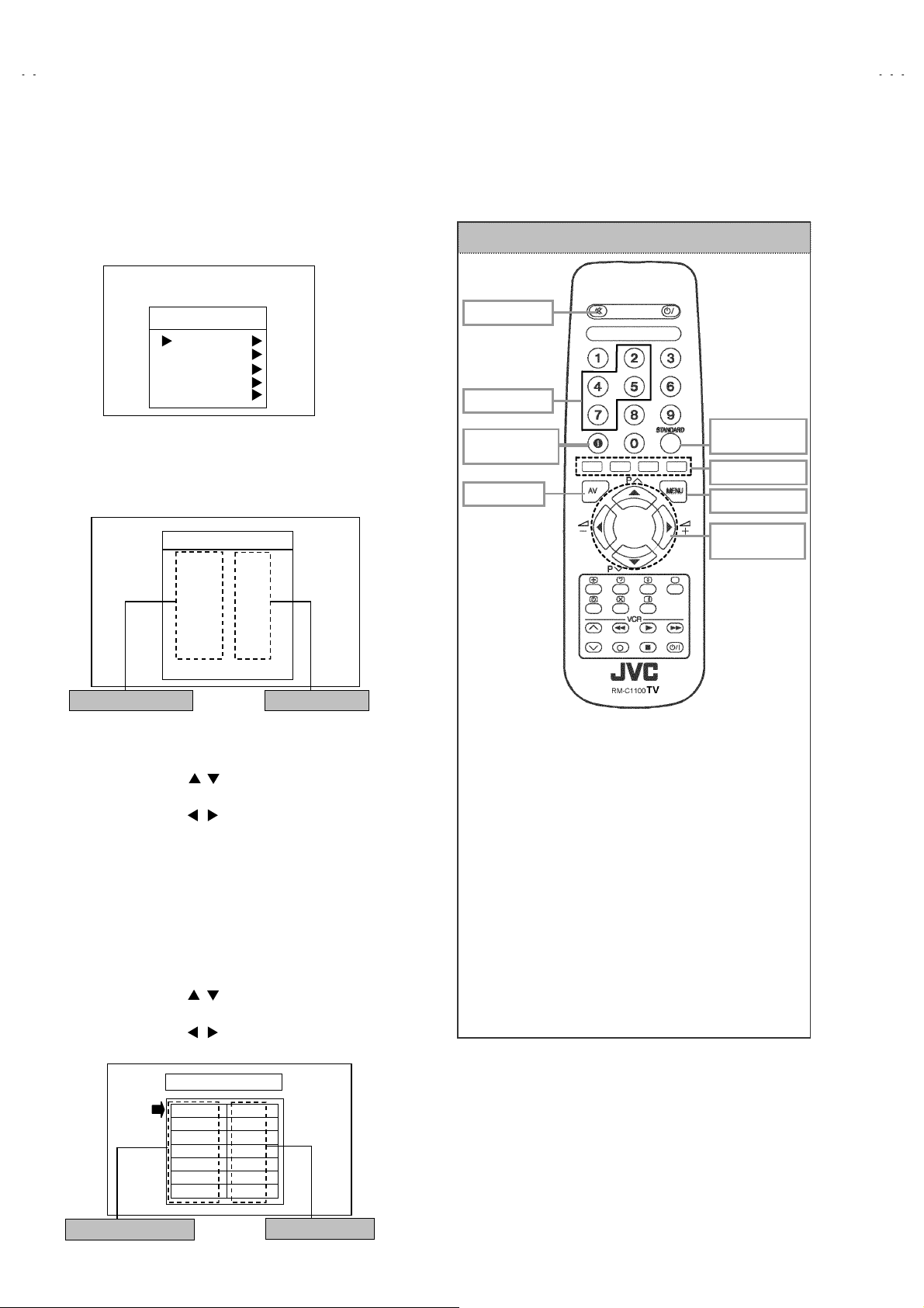
SERVICE MENU
Fig.1
SERVICE MENU SELECT KEY
(4) SERVICE MENU setting
1) Press MENU key and, while the displayed MENU
screen, press 4, 7, 2, 5 key on the remote control unit or
press MUTING key and INFORMATION key at the
simultaneously.
2) The SERVICE MENU screen of Fig.1 is displayed.
3) Verif y what to set in the SERVICE MENU, and set
whatever is necessary (Fig.1). Refer to the SERVICE
ADJUSTMENT for setting.
4) Press the STANDARD key to exit SERVICE MENU.
(5) Receive channel setting
Refer to the OPERATING INSTRUCTIONS (USER’S
GUIDE) and set the receive channels (Channels Preset) as
described.
(6) User settings
Check the user setting items acc ording to after page.
Where these do not agree, refer to the OPERATING
INSTRUCTIONS (USER’S GUIDE) and set the items as
described.
MUT ING
INFO RMATIO N
ITE M
SELECT(▲)
VALUE
SELECT(-)
FUNCTION
Fig.2
POWER
NUMBER
STANDARD
COLOUR key
MENU
VALUE
SELECT(+)
ITE M
SELECT(▼)
TELETEXT
No. 52084
9
Page 10

A
V-29BF11ENS
A
A
V-29BF11EPS
V-29BF11EES
SETTING OF THE LAST MEMORY FOR SHIPMENT
■■■■ USER SETTING VALUES
Setting Item Setting Value Setting Item Setting Value
SOUND MENU FEATURE MENU
BALANCE CENTER SLEEP TIMER OFF
BASS
TREBLE
EFFECT OFF AV-2 OUTPUT TV
PICTURE MENU INSTALL
BRIGHTNESS PROGRAMME
CONTRAST BAND
COLOUR CHANNEL
SHARPNESS SEARCH
HUE (only NTSC)
PICTURE MODE AUTO STORE
SETTING APS BIT IN SERVICE MENU
■
1) Enter service menu in TV mode by pressing “INFORMATION” and “MUTING” keys simultaneously. S ervice Menu will appear.
2) Select TX1(TELETEXT OPTION) by pressing Up/Down keys on remote c ontrol unit.
3) Press the 7 key on remote control unit to set APS bit. (After this, bit 7 of TX1 will be “1”). (Do not change any other bit.)
4) Press STANDARD key on remote control unit to exit s ervice mode.
NOTE : DO NOT TURN OFF THE TV BY USING POWER BUTTON ON THE FRONT PANEL.
These adjust are automatically
restored when APS bit in Service
menu is s et.
The proc edure f or setting APS
bit is described bellow.
↑
↑
CHILD LOCK OFF
LANGUAGE ENGLISH
Refer to the INSTRUCTION
BOOK.
FINE TUNING
10
No. 52084
Page 11

A
A
A
SERVICE ADJUSTMENTS
ADJUSTMENT PREPARATION
1. You can make the necessary adjustments for this unit with
either the Remote Control Unit or with the adjustment tools
and parts as given belo w.
2. Adjustment with the Remote Control Unit is made on the
basis of the initial setting values, however, the new setting
values which set the screen to its optimum condition may
differ from the initial settings.
3. Make sure that AC power is turned on correctly.
4. Turn on the power for set and test equipment before use, and
start the adjustment procedures after waiting at least 30 minutes.
5. Unless otherwise specified, prepare the most suitable reception
or input signal for adjustment.
6. Never touch any adjustment parts which are not specified in the
list for this adjustment - variable resistors, transformers,
condensers, etc.
7. Presetting before adjustment.
Unless otherwise specified in the adjustment instructions, pr eset
the following functions with the remote control unit.
BRIGHTNESS
CONTRAST
COLOUR
SHARPNESS
V-29BF11ENS
V-29BF11EPS
V-29BF11EES
CENTER
ADJUSTMENT EQUIPMENT
1. DC voltmeter (or digital voltmeter)
2. Signal generator (Pattern generator)[PAL/SECAM/NTSC]
3. Remote c ontrol unit
MAIN PARTS LOCATIONS
HEADPHONE JACK
FRONT
VIDEO
RL
AUDIO.
LED
REMOCON
RECEIVER
ADJUSTMENT ITEM
! SCREEN ADJUSTMENT
! OSD HORIZONTAL POSITION ADJUSTMENT
! IF ADJUSTMENT
! AGC AUTOMATICALLY ADJUSTMENT
! DEFLECTION CIRCUIT ADJUSTMENT
! GEOMETRY MENU ADJUSTMENT
! WHITE BALANCE ADJUSTMENT
! TXT BRIGHTNESS ADJUSTMENT
MENU
FRONT AV & HEADPHONE PWB FRONT CONTROL PWB
IC500
IC501
MEMOR Y IC
MICOM
(+)
(+) (-)
(-)
(+)(+)
(-)(-)
PROG
/Ch.
(+)
(+) (-)
(-)
(+)(+)
(-)(-)
VOL
TOP
FRONT
FBT
SCART
jack
TUNER
AV-1 AV-2
SCART
jack
MAIN PWB
No. 52084
UPPER : FOCUS VR
LOWER : SCREEN VR
11
Page 12
A
V-29BF11ENS
A
A
V-29BF11EPS
V-29BF11EES
BASIC OPERATION SERVICE MENU
■■■■ HOW TO ENTER THE SERVICE MENU
1) Press the MENU key.
2) MENU screen of fig.1 will be displayed
MENU SCREEN
REMOTE CONTROL UNIT key NAME
MENU
SOUND
PICTURE
FEAT URE
INSTALL
PROGRAM
Fig.1
3) W hile the MENU screen is displayed , press the 4,7,2,5 key or
INFORMATION key and MUTING key simultaneously.
4) The SERVICE MENU screen (Fig.2) will be displayed.
SERVICE MENU
JVCAK30/37 B04
OSD
IF1
IF2
IF3
IF4
AGC
VLIN
RGBH
VSOF
VPOF
: 0 1
059
004
065
004
065
033
044
005
+05
-01
ADJUSTMENT ITEM SETTING VALUE
Fig.2
■ SELECTION OF ADJUSTMENT ITEMS
1) Enter the SERVICE MENU
2) Press the FUNCTION / key and select the ADJUSTMENT
ITEM.
3) Press the FUNCTION / key and set the SETT ING VALUE.
■ HOW TO EXIT SERVICE MODE
1) Press the ST ANDARD Key on REMOTE CONTROL UNIT.
■ HOW TO ENTER THE GEOMETRY MENU
" This model is built-in GEOMETRY MENU f or geometry
adjustment. For details, refer to the adjustment.
1) Enter the SERVICE MENU
2) Press the GREEN key, geometry menu appears (Fig. 3).
3) Press the FUNCTION / key and select the ADJUSTMENT
ITEM.
4) Press the FUNCTION / key and set the SETT ING VALUE.
GEOMETRY MENU
MUTING key
NUMBER key
INFORMATION
key
AV key
" FUNCTION OF COLOUR key
RED key :
It switches the AVL(Automatic volume control) to
ON or OFF mode on service menu. AVL word is
visible on service menu when AVL is on.
GREEN key :
It switches to GEOMETRY adjust menu. Geometry
of the picture is adjust ed in this menu.
YELLOW key :
It switches to VERTICAL SCAN DISABLE mode.
It is useful to adjust screen voltage.
BLUE key :
It is used to adjust AGC and IF automatically on
service menu.
STANDARD
key
COLOUR key
MENU key
FUNCTION
key
GEOMETRY
VSIZ 038
VPOS 022
VSCO 005
VCCO 007
HSIZ 009
HPOS 030
HPIN 014
ADJUSTMENT ITEM
Fig.3
12
SETTING VALUE
No. 52084
Page 13

A
A
A
■ ADJUSTMENT ITEM & INITIAL SETTING VALUE in the SERVICE MENU
ADJUSTMENT
ITEM
OSD HORIZONTAL POSITION OF OSD 059
IF1 IF COARSE ADJUSTMENT 004
IF2 IF FINE ADJUSTMENT 065
IF3 IF COARSE ADJUSTMENT FOR L-PRIME 004
IF4 IF FINE ADJUSTMENT FOR L-PRIME 065
AGC AUTOMATIC GAIN CONTROL Automatically
VLIN VERTICAL LINEARITY Not used
RGBH RGB MODE HORIZONTAL SHIFT OFFSET 005
VSOF VERTICAL SIZE OFFSET for 60Hz +05
VPOF VERTICAL POSITION OFFSET for 60Hz -01
HSOF HORIZONTAL SIZE OFFSET for 60Hz -02
HPOF HORIZONTAL POSITION OFFSET for 60Hz -06
HTOF HORIZONTAL TRAPEZOID OFFSET for 60Hz -03
WR WHITE POINT ADJUSTMENT FOR RED 030
WG WHITE POINT ADJUSTMENT FOR GREEN 030
WB W HITE POINT ADJUSTMENT FOR BLUE 030
BR BIAS FOR RED 028
BG BIAS FOR GREEN 029
APR AUTOMATIC RGB PEAK REGULATION THRESHOLD 004
BRI BRIGHTNESS 032
CON CONTRAST 033
COL COLOUR 030
SHR SHARP 006
HUE HUE 031
VOL VOLUME 009
WR-R WHITE POINT ADJUSTMENT for RED (RGBmode) 022
WG-R WHITE POINT ADJUSTMENT for GREEN (RGBmode) 032
WB-R WHITE POINT ADJUSTMENT for BLUE (RGBmode) 022
FMP1 FM PRESCALER WHEN AVL IS OFF Not used
NIP1 NICAM PRESCALER W HEN AVL IS OFF Not used
SCP1 SCART PRESCALER WHEN AVL IS OFF Not used
SEC1 SECAM PRESCALER WHEN AVL IS OFF Not used
FMP2 FM PRESCALER WHEN AVL IS ON 015
NIP2 NICAM PRESCALER W HEN AVL IS ON 045
SCP2 SCART PRESCALER WHEN AVL IS ON 017
SEC2 SECAM PRESCALER WHEN AVL IS ON Not used
F1H HIGH BYTE OF VHF1-VHF3 CROSS-OVER FREQUENCY 00001001
F1L LOW BYTE OF VHF1-VHF3 CROSS-OVER FREQUENCY 10010010
F2H HIGH BYTE OF VHF3-UHF CROSS-OVER FREQUENCY 00011011
F2L LOW BYTE OF VHF3-UHF CROSS-OVER FREQUENCY 10000010
BS1 BAND SWITCHING BYTE FOR VHF1 00000011
BS2 BAND SWITCHING BYTE FOR VHF3 00000110
BS3 BAND SWITCHING BYTE FOR UHF 10000101
CB CONTROL BYTE 10001110
DESCRIPTION INITIAL VALUE
V-29BF11ENS
V-29BF11EPS
V-29BF11EES
1/2
No. 52084
13
Page 14

A
V-29BF11ENS
A
A
V-29BF11EPS
V-29BF11EES
ADJUSTMENT
ITEM
OP1 PERIPHERAL OPTIONS 11110111
OP2 RECEPTION STANDARD OPTIONS
OP3 VIDEO OPTIONS
OP4 TV FEATURES 10001000
OP5 CHANNEL TABLES 0000000D
TX1 TELETEXT OPTIONS
GEOM GEOMETRY OPTIONS 00100000
OP8 PIP PR ESET CHANGE 00000100
DESCRIPTION INITIAL VALUE
00001001 (EN)
01011001 (EP)
00011001 (EE)
01101100(EN)
11101100(EP/EE)
11010101 (EN)
11000101 (EP)
11001101 (EE)
[GEOMETRY MENU]
ADJUSTMENT
ITEM
VSIZ VERTICAL SIZE for 50Hz 038 009
VPOS VERTICAL POSITION f or 50Hz 022 025
VSCO VERTICAL S-CORRECTION for 50Hz 005 005
VCCO VERTICAL CORNER CORRECTION for 50Hz 007 007
HSIZ HORIZONTAL SIZE for 50Hz 009 013
HPOS HORIZONTAL POSITION for 50Hz 030 030
HPIN HORIZONTAL PINCUSHION for 50Hz 014 012
HCCO HORIZONTAL CORNER CORRECTION for 50Hz 010 010
HTRP HORIZONTAL TRAPEZOID for 50Hz 013 018
VZSZ VERTICAL ZOOM SIZE for 50Hz Not used Not used
DESCRIPTION
4:3 MODE 16:9 MODE
INITIAL VALUE
2/2
14
No. 52084
Page 15

A
A
A
ADJUSTMENTS
■■■■ SCREEN ADJUSTMENT
V-29BF11ENS
V-29BF11EPS
V-29BF11EES
Item
SCREEN
adjustment
Measurin g
instrument
Remote
control unit
Test point Adjustment part Description
SCREEN VR
[On the FBT]
■■■■ OSD HORIZONTAL POSITION ADJUSTMENT
Item
HORIZONTAL
POSITION OF
OSD
adjustment
Measurin g
instrument
Test point Adjustment part Description
Remote
control unit
SERVICE MENU SCREEN
JVCAK30/37 B04
OSD
059
IF1
004
IF2
065
IF3
004
IF4
065
AGC
033
VLIN
044
RGBH
005
VSOF
+05
VPOF
: 1 1
-01
OSD 1. Enter SERVICE MENU.
Referenc e bar
1. Enter SERVICE MENU.
2. Press YELLOW key to disable vertical scan.
3. Adjust SCREEN VR. on the FBT as thin as possible.
4. Press YELLOW key again to enable vertical scan.
5. Press STANDARD key to leave service menu.
FOCUS VR
SCREEN VR
FBT
2. Select OSD (On screen display) with FUNCTION ( / ) key
3. Adjust the OSD horizontal position with the FUNCTION ( / )
key, which shifts the reference bar on the bottom of the
SERVICE MENU horizontally, so that the OSD is positioned on
the screen cent er. (X=X’)
XX’
Screen size
■■■■ IF ADJUST MENT
Item
IF adjustment Remote
Measurin g
instrument
control unit
Test point Adjustment part Description
IF 1
IF 2
IF 3
IF 4
1. Receive a PAL colour bar pattern.
2. Enter SERVICE MENU.
3. Select IF 1 with FUNCTION ( / ) key
4. Press BLUE key during IF 1 is highlighted, IF 1 and IF 2 values
are adjusted automatically by software.
5. If the standard is L-prime, IF 3 and IF 4 values are adjustment
automatically when BLUE key is press ed during IF 1 is
highlighted.
No. 52084
15
Page 16

A
V-29BF11ENS
A
A
V-29BF11EPS
V-29BF11EES
■■■■ AGC AUTOMATICALLY ADJUSTMENT
Item
AGC
AUTOMATIC-
Measurin g
instrument
Remote
control unit
Test point Adjustment part Description
AGC 1. Enter SERVICE MENU.
ALLY
adjustment
& check
SERVICE MENU SCREEN
JVCAK30/37 B04
059
OSD
004
IF1
065
IF2
004
IF3
065
IF4
033
AGC
044
VLIN
005
RGBH
+05
VSOF
-01
VPOF
: 1 1
■■■■ DEFLECTION CIRCUIT ADJUSTMENT
Item
RGB M ODE
HORIZONTAL
SHIFT
OFFSET
adjustment
Measurin g
instrument
Signal
generator
Remote
control unit
A
Test point Adjustment part Description
RGBH 1. Input R/G/B circle pattern signal via video input terminal.
B
2. Receive a 60dBμV RF signal level.
3. Select AGC with the FUNCTION ( / ) key.
4. Press BLUE key on the remote control unit.
5. Then the adjustment will be done automatically by software.
6. See the AGC indicator on SERVICE MENU, it must be “1”.
7. Check that picture is normal at 90dBμV signal level.
:11
IF INDICATOR AGC INDICATOR NONE
2. Press AV key on the remote control unit, f orce the TV to RGB
mode.
3. Enter SERVICE MENU.
4. Select RGBH (RGB mode horizontal shift) with the
FUNCTION ( / ) key.
5. Adjust RGBH with the FUNCTION ( / ) key until the circle
pattern is horizontally center ed.(A=B)
6. Check and readjust RGBH item if the adjustment becomes
improper after some other geometric adjustments are done.
VERTICAL
SIZE OFFSET
adjustment
(60Hz)
Signal
generator
Remote
control unit
VSOF 1. Receive a NTSC-M cross-hatch pattern of vertical frequency
60Hz.
2. Enter SERVICE MENU.
3. Select VSOF (Vertical size) with the FUNCTION ( / ) key.
4. Adjust VSOF with the FUNCTION ( / ) key until the
horizontal black lines on both the upper and lower part of the
Very close
pattern become very close to the upper and lower horizontal
sides of picture size and nearly about to disappear.
5. Check and readjust VSOF item if the adjustment becomes
improper after some other geometric adjustments are done.
Screen
size
Picture
size
100%
Very close
16
No. 52084
Page 17

A
V-29BF11ENS
A
A
V-29BF11EPS
V-29BF11EES
Item
VERTICAL
POSITION
OFFSET
adjustment
(60Hz)
HORIZONTAL
SIZE
OFFSET
adjustment
(60Hz)
Measurin g
instruments
Signal
generator
Remote
control unit
Signal
generator
Remote
control unit
Picture size 100%
Test point Adjustment part Description
VPOF 1. Receive a NTSC-M circle pattern of vertical fr equency 60Hz.
2. Enter SERVICE MENU.
3. Select VPOF (Vertical position) with the FUNCTION ( / )
key.
4. Adjust VPOF with the FUNCTION ( / ) key until the
picture is vertically centered.(C=D)
5. Check and readjust vertical position item if the adjustment
becomes improper after some other geometric adjustments
C
D
HSOF 1. Receive a NTSC-M cross-hatch patt ern of vertical frequency
are done.
60Hz.
2. Enter SERVICE MENU.
3. Select HSOF (Horizontal size) with the FUNCTION ( / )
key.
4. Adjust HSOF with the FUNCTION ( / ) key until the
vertical black lines on both the left and right part of the
pattern become very close to the left and right vertical sides
of picture size and nearly about to disappear.
5. Check and readjust a HSOF item if the adjustment becomes
improper after some other geometric adjustments are done.
Very close
HORIZONTAL
POSITION
OFFSET
adjustment
(60Hz)
Signal
generator
Remote
control unit
E
Screen size
Very close
HPOF 1. Receive a NTSC-M circle pattern signal of vertical frequency
60Hz.
2. Enter SERVICE MENU.
3. Select HPOF (Horizontal position) with the FUNCTION ( / )
key.
4. Adjust HPOF with the FUNCTION ( / ) key until the circle
F
pattern is horizontally centered.(E=F)
6. Check and readjust a horizontal position item if the adjustment
becomes improper after s ome other geometric adjustments
are done.
No. 52084
17
Page 18

A
V-29BF11ENS
A
A
V-29BF11EPS
V-29BF11EES
Item
HORIZONTAL
TRAPEZOID
OFFSET
adjustment
(60Hz)
Measurin g
instruments
Signal
generator
Remote
control unit
Test point Adjustment part Description
HTOF 1. Receive a NTSC-M cross-hatch patter n signal of vertical
frequency 60Hz.
2. Enter SERVICE MENU.
3. Select HTOF with the FUNCTION ( / ) key.
4. Adjust HTOF with the FUN CTION ( / ) key until both
lengths of the upper side and lower side of the closs-hatch
pattern become equal.
Pallalel
18
No. 52084
Page 19

A
A
A
■■■■ GEOMETRY MENU ADJUSTMENT (Adjust 4:3MODE / 16:9MODE respectively)
V-29BF11ENS
V-29BF11EPS
V-29BF11EES
Item
VERTICAL
SIZE
adjustment
(50Hz)
Very close
Screen
size
Very close
VERTICAL
POSITION
adjustment
(50Hz)
Measurin g
instruments
Signal
generator
Remote
control unit
Signal
generator
Remote
control unit
Test point Adjustment part Description
VSIZ 1. Receive a PAL B/G cross-hatch pattern of vertical frequency
50Hz.
2. Enter SERVICE MENU.
3. Press the GREEN key on the remove control unit then enter
the GEOMETRY MENU.
4. Select VSIZ (Vertical size) with the FUNCTION ( / ) key.
5. Adjust VSIZ with the FUNCTION ( / ) key until the
horizontal black lines on both the upper and lower part of the
pattern become very close to the upper and lower horizontal
sides of picture size and nearly about to disappear.
6. Check and readjust VSIZ item if the adjustment becomes
Picture
size
100%
VPOS 1. Receive a PAL B/G circle pattern signal of vertical frequenc y
A
improper after some other geometric adjustments are done.
50Hz.
2. Enter GEOMETRY MENU.
3. Select VPOS (Vertical position) with the FUNCTION ( / )
key.
4. Adjust VPOS with the FUNCTION ( / ) key until the circle
pattern is vertic ally centered.(A=B)
5. Check and readjust VPOS item if the adjustment becomes
improper after some other geometric adjustments are done.
VERTICAL
S-CORRECTION
adjustment
(50Hz)
Signal
generator
Remote
control unit
B
VSCO 1. Receive a PAL B/G cross-hatch pattern signal of vertical
frequency 50Hz.
2. Enter GEOMETRY MENU.
3. Select VSCO (Vertical s-correction) with the FUNCTION
( / ) key.
4. Adjust VSCO with the FUNCTION ( / ) key until the vertical
length of the center squarer of the cross-hatch pattern
becomes equal to upper and lower part squares of the crosshatch pattern.
5. Check and readjust VSCO item if the adjust ment becomes
improper after some other geometric adjustments are done.
No. 52084
19
Page 20

A
V-29BF11ENS
A
A
V-29BF11EPS
V-29BF11EES
Item
VERTICAL
CORNER
CORRECTION
adjustment
(50Hz)
HORIZONTAL
SIZE
adjustment
(50Hz)
Measurin g
instrument
Signal
generator
Remote
control unit
Signal
generator
Remote
control unit
Picture size 100%
Test point Adjustment part Description
VCCO 1. Receive a PAL B/G cr oss-hatch pattern signal of vertical
frequency 50Hz.
2. Enter GEOMETRY MENU.
3. Select VCCO (Vertical corner correction) with the FUNCTION
( / ) key.
4. Adjust VCCO with the FUNCTION ( / ) key until the vertical
length of the upper and lower part squares of the cross-hatch
pattern become equal to each other.
5. Check and readjust VCCO it em if the adjustment becomes
improper after some other geometric adjustments are done.
HSIZ 1. Receive a PAL B/G cross- hatch pattern signal of vertical
frequency 50Hz.
2. Enter GEOMETRY MENU.
3. Select HSIZ (Horizontal size) with the FUNCTION ( / ) key.
4. Adjust HSIZ with the FUNCTION ( / ) key until the vertical
black lines on both the left and right part of the cross-hatch
pattern become very close to the left and right horizontal sides
of picture tube and nearly about to dis appear.
HORIZONTAL
POSITION
adjustment
(50Hz)
Very close
Signal
generator
Remote
control unit
C
Screen size
Very close
HPOS 1. Receive a PAL B/G circle pattern signal of vertic al frequency
50Hz.
2. Enter GEOMETRY MENU.
3. Select HPOS (Horizontal position) with the FUNCTION ( / )
key.
4. Adjust HPOS with the FUNCTION ( / ) key until the circle
D
pattern is horizontally centered.(C=D)
5. Check and readjust HPOS item if the adjustment becomes
improper after some other geometric adjustments are done.
20
No. 52084
Page 21

A
V-29BF11ENS
A
A
V-29BF11EPS
V-29BF11EES
Item
HORIZONTAL
PINC USHION
adjustment
(50Hz)
HORIZONTAL
CORNER
CORRECTION
adjustment
(50Hz)
Measurin g
instrument
Signal
generator
Remote
control unit
Signal
generator
Remote
control unit
Test point Adjustment part Description
HPIN 1. Receive a PAL B/G cr oss-hatch pattern signal of vertical
frequency 50Hz.
2. Enter GEOMETRY MENU.
3. Select HPIN (Horizontal pincushion) with the FUNCTION
( / ) key.
4. Adjust HPIN with the FUNCTION ( / ) key until the bending
of the vertical line of the cross-hatch pattern are c orrected.
5. Check and readjust HPIN item if the adjustment becomes
improper after some other geometric adjustments are done.
HCCO 1. Receive a PAL B/G cross-hatch pattern signal of vertical
frequency 50Hz.
2. Enter GEOMETRY MENU.
3. Select HCCO (Horizontal corner correction) with the
FUNCTION ( / ) key.
4. Adjust HCCO with the FUNCTION ( / ) key until the bending
of the vertical line of the cross-hatch pattern are c orrected.
5. Check and readjust HCCO item if the adjustment becomes
improper after some other geometric adjustments are done.
HORIZONTAL
TRAPEZOID
adjustment
(50Hz)
Signal
generator
Remote
control unit
HTRP 1. Receive a PAL B/G cross-hatch pattern signal of vertical
frequency 50Hz.
2. Enter GEOMETRY MENU.
3. Select HTRP (Horizontal trapezoid) with the FUNCTION
( / ) key.
4. Adjust HTRP with the FUNCTION ( / ) key until both lengths
of the upper side and lower side of t he cross-hatch pattern
A
B
become equal.(A=B)
No. 52084
21
Page 22

AV-29BF11ENS
AV-29BF11EPS
AV-29BF11EES
■■■■ WHITE BALANCE ADJUSTMENT
Item
WHITE
BALANCE
adjustment
(Low light)
Measuring
instrument
Signal
generator
Remote
control unit
Test point Adjustment part Description
WR
WG
WB
Item WR WG WB
1. Receive a black & white signal (colour off).
2. Enter SERVICE MENU.
3. Select WR / WG / WB with the ( / ) key, respectively.
4. Adjust WR / WG / WB with the FUNCTION ( / ) key,
respectively, until the white part turns to pure white without any
other colour.
Initial setting value
WHITE
BALANCE
adjustment
(High light)
Signal
generator
Remote
control unit
Initial setting value
■■■■ TXT BRIGHTNESS ADJUSTMENT
Item
TELETEXT
BRIGHTNESS
adjustment
Measuring
instrument
Remote
control unit
Test point Adjustment part Description
030 030 030
BR
BG
Item BR BG
1. Receive a black & white signal (colour off)
2. Enter SERVICE MENU.
3. Select BR / BG with the FUNCTION ( / ) key respectively.
4. Adjust BR / BG with the FUNCTION ( / ) key respectively,
until the white part of screen make white colour.
028 029
1. Receive a teletext broadcast.
2. Enter the SERVICE MENU.
3. Press the TELETEXT key on the remote control unit, then
change TXT brightness.
4. Adjust the TXT brightness with FUNCTION ( / ) key.
5. Press the TELETEXT key again. You can return to the
SERVICE MENU.
22
No. 52084
Recommended value
TXT BRIGHTNESS
025
Page 23

A
A
A
PARTS LIST
CONTENTS
V-29BF11ENS
V-29BF11EPS
V-29BF11EES
! USING P.W. BOARD & REMOTE CONTROL UNIT
! EXPLODED VIEW PARTS LIST
! EXPLODED VIEW
・・・・・・・・・・・・・・・・・・・・・・・・・・・・・・・・・・・・・・・・・・・・・・・・・・・・・・・・・・・・・・・・・・・・・・・・・・・・・・・・・・・・・・・・
・・・・・・・・・・・・・・・・・・・・・・・・・・・・・・・・・・・・・・・・・・・・・・・・・・・・・・・・・・・・・・・・・・・・・・・・・・
・・・・・・・・・・・・・・・・・・・・・・・・・・・・・・・・・・・・・・・・・・・・・・・・・・・・・
! PRINTED WIRING BOARD PARTS LIST
[ AV-29BF11ENS]
" MAIN P.W. BOARD ASS'Y ・・・・・・・・・・・・・・・・・・・・・・・・・・・・・・・・・・・・・・・・・・・・・・・・・・・・・・・・・・・・・・・・・・・・・・・・・・・・・・・・・・・・・
" CRT SOCKET P.W . BOARD ASS'Y ・・・・・・・・・・・・・・・・・・・・・・・・・・・・・・・・・・・・・・・・・・・・・・・・・・・・・・・・・・・・・・・・・・・・・・・・・・・・・
" FRONT AV & HEADPHONE P.W . BOARD ASS’Y ・・・・・・・・・・・・・・・・・・・・・・・・・・・・・・・・・・・・・・・・・・・・・・・・・・・・・・・・・・・・・・・・・
" FRONT CONTROL P.W. BOARD ASS’Y・・・・・・・・・・・・・・・・・・・・・・・・・・・・・・・・・・・・・・・・・・・・・・・・・・・・・・・・・・・・・・・・・・・・・・・・・
[ AV-29BF11EPS]
" MAIN P.W. BOARD ASS'Y ・・・・・・・・・・・・・・・・・・・・・・・・・・・・・・・・・・・・・・・・・・・・・・・・・・・・・・・・・・・・・・・・・・・・・・・・・・・・・・・・・・・・・
" CRT SOCKET P.W . BOARD ASS'Y ・・・・・・・・・・・・・・・・・・・・・・・・・・・・・・・・・・・・・・・・・・・・・・・・・・・・・・・・・・・・・・・・・・・・・・・・・・・・・
" FRONT AV & HEADPHONE P.W . BOARD ASS’Y ・・・・・・・・・・・・・・・・・・・・・・・・・・・・・・・・・・・・・・・・・・・・・・・・・・・・・・・・・・・・・・・・・
" FRONT CONTROL P.W. BOARD ASS’Y・・・・・・・・・・・・・・・・・・・・・・・・・・・・・・・・・・・・・・・・・・・・・・・・・・・・・・・・・・・・・・・・・・・・・・・・・
[ AV-29BF11EES]
" MAIN P.W. BOARD ASS'Y ・・・・・・・・・・・・・・・・・・・・・・・・・・・・・・・・・・・・・・・・・・・・・・・・・・・・・・・・・・・・・・・・・・・・・・・・・・・・・・・・・・・・・
" CRT SOCKET P.W . BOARD ASS'Y ・・・・・・・・・・・・・・・・・・・・・・・・・・・・・・・・・・・・・・・・・・・・・・・・・・・・・・・・・・・・・・・・・・・・・・・・・・・・・
" FRONT AV & HEADPHONE P.W . BOARD ASS’Y ・・・・・・・・・・・・・・・・・・・・・・・・・・・・・・・・・・・・・・・・・・・・・・・・・・・・・・・・・・・・・・・・・
" FRONT CONTROL P.W. BOARD ASS’Y・・・・・・・・・・・・・・・・・・・・・・・・・・・・・・・・・・・・・・・・・・・・・・・・・・・・・・・・・・・・・・・・・・・・・・・・・
23
24
25
26
30
30
30
31
30
30
30
35
30
30
30
! PACKING / PACKING PARTS LIST
・・・・・・・・・・・・・・・・・・・・・・・・・・・・・・・・・・・・・・・・・・・・・・・・・・・・・・・・・・・・・・・・・・・・・・
USING P.W. BOARD & REMOTE CONTROL UNIT
Model
PWB AS S'Y
MAIN PWB
CRT SOCKET PWB
FRONT AV & HEADPHONE
PWB
FRONT CONTROL PWB VE-20100168
REMOTE CONTROL UNIT
AV-29BF11ENS AV-29BF11EPS AV-29BF11EES
VE-20103272 VE-20103267 VE-20103265
VE-20094670
VE-20083646
VE-30017763
(RM-C1100)
39
No. 52084
23
Page 24

A
V-29BF11ENS
A
A
V-29BF11EPS
V-29BF11EES
EXPLODED VIEW PARTS LIST
[ AV-29BF11ENS, AV-29BF11EPS, AV-29BF11EES ]
! Ref.No. Part No. Part Name Description
! V01 VE-20098924 CRT KIT Inc. DEG COIL(VE-30012971),
! TR601 VE-30017522 FBT
! 1 VE-300 12971 DEG COIL&EARTH CB.
3 VE-35000013 SPRING(ON/OFF SWITCH)
! 4 VE-20059930 BUTTON(ON/OFF)
! 5 VE-20003605 PIN(CONTROL PANEL DOOR)(×2)
! 6 VE-40000026 EJECTOR CLIP-CLAP
! 7 VE-20102640 CONTROL PANEL DOOR
! 8 VE-20103272 FRONT PANEL
! 9 VE-20081212 LENS LED
! 10 VE-20082371 BUTTON FUNCTION
11 VE-40009351 SPONGE (×2)
12 VE-30001950 SPEAKER(8R 15W) (×2)
13 VE-30001947 TWEETER(8R 15W) (×2)
! 14 VE-20097423 BACK COVER(REAR COVER)
15 VE-35004572 SCREW (×8)
! 16 VE-20067720 BACK DOOR(TERMINAL BOARD)
17 VE-35000211 SCREW (×4)
18 VE-40009154 JVC LOGO
! 19 VE-20103656 LABEL [AV-29BF11ENS]
! 19 VE-20103677 LABEL [AV-29BF11ENS(for GER models)]
! 19 VE-20103679 LABEL [AV-29BF11ENS(for ITA models)]
! 19 VE-20103654 LABEL [AV-29BF11EPS]
! 19 VE-20103640 LABEL [AV-29BF11EES]
! 19 VE-20103638 LABEL [AV-29BF11EES(for POL models)]
! 20 VE-30002174 MAIN SWITCH (ON/OFF)
! -- VE-30016513 POWER CORD 2.2MT(W/FILTER)
! -- VE-50025747 WARNING LABEL(HUN) [AV-29BF11EES]
CONN.ASSY,SPRING
24
No. 52084
Page 25

A
A
A
EXPLODED VIEW
!
19
17
!
16
V-29BF11ENS
V-29BF11EPS
V-29BF11EES
15
!
14
MAIN PWB
!
TR601
!
!
V01
FRONT
CONTROL
PWB
11
!
8
12
13
!
6
!
1
11
12
5
!
9
13
!
!
10
20
FRONT AV &
18
!
3
!
4
7
HEADPHONE
PWB
No. 52084
25
Page 26

A
V-29BF11ENS
PRINTED WIRING BOARD PARTS LIST
[ AV-29BF11ENS ]
MAIN P.W. BOARD ASS’Y (VE-20103272)
! Symbol No. Part No. Part Name Description
VARIABLE RESISTOR
VR800 VE-30001064 RES ADJ 1/10W 470R VER (MAN)
RESISTOR
R102 VE-30012657 SMD RES. 1/16W 1K J
R103 VE-30012657 SMD RES. 1/16W 1K J
R106 VE-30012713 SMD RES. 1/16W 75R J
R107 VE-30012649 SMD RES. 1/16W 150R J
R109 VE-30012713 SMD RES. 1/16W 75R J
R110 VE-30012713 SMD RES. 1/16W 75R J
R111 VE-30012649 SMD RES. 1/16W 150R J
R113 VE-30012713 SMD RES. 1/16W 75R J
R114 VE-30012713 SMD RES. 1/16W 75R J
R115 VE-30012713 SMD RES. 1/16W 75R J
R117 VE-30000792 CF RES. 1/4W 75R J
R118 VE-30012713 SMD RES. 1/16W 75R J
R121 VE-30012649 SMD RES. 1/16W 150R J
R122 VE-30000792 CF RES. 1/4W 75R J
R123 VE-30000792 CF RES. 1/4W 75R J
R124 VE-30012649 SMD RES. 1/16W 150R J
R126 VE-30012657 SMD RES. 1/16W 1K J
R129 VE-30012713 SMD RES. 1/16W 75R J
R135 VE-30012657 SMD RES. 1/16W 1K J
R137 VE-30000466 CF RES. 1/4W 1K J
R138 VE-30012657 SMD RES. 1/16W 1K J
R139 VE-30012713 SMD RES. 1/16W 75R J
R141 VE-30012657 SMD RES. 1/16W 1K J
R145 VE-30012713 SMD RES. 1/16W 75R J
R149 VE-30012703 SMD RES. 1/16W 56K J
R151 VE-30012696 SMD RES. 1/16W 47K J
R152 VE-30000752 CF RES. 1/4W 56K J
R153 VE-30012657 SMD RES. 1/16W 1K J
R154 VE-30000723 CF RES. 1/4W 47K J
R155 VE-30012649 SMD RES. 1/16W 150R J
R169 VE-30012703 SMD RES. 1/16W 56K J
R171 VE-30012713 SMD RES. 1/16W 75R J
R172 VE-30012692 SMD RES. 1/16W 4.7K J
R174 VE-30012713 SMD RES. 1/16W 75R J
R175 VE-30012713 SMD RES. 1/16W 75R J
R176 VE-30012703 SMD RES. 1/16W 56K J
R201 VE-30012674 SMD RES. 1/16W 27K J
R202 VE-30012692 SMD RES. 1/16W 4.7K J
R204 VE-30000459 CF RES. 1/4W 100R J
R206 VE-30000459 CF RES. 1/4W 100R J
R319 VE-30014076 SMD RES. 1/16W 4.7R J
R320 VE-30014076 SMD RES. 1/16W 4.7R J
R324 VE-30012667 SMD RES. 1/16W 220K J
R328 VE-30012649 SMD RES. 1/16W 150R J
R329 VE-30012692 SMD RES. 1/16W 4.7K J
R332 VE-30012641 SMD RES. 1/16W 10K J
R333 VE-30012702 SMD RES. 1/16W 560R J
R338 VE-30012641 SMD RES. 1/16W 10K J
R340 VE-30012644 SMD RES. 1/16W 12K J
R341 VE-30012702 SMD RES. 1/16W 560R J
R343 VE-30012659 SMD RES. 1/16W 2.2K J
R370 VE-30012669 SMD RES. 1/16W 22K J
R371 VE-30012669 SMD RES. 1/16W 22K J
R391 VE-30012696 SMD RES. 1/16W 47K J
R417 VE-30012510 SMD RES. 1/16W 100R J
R418 VE-30012510 SMD RES. 1/16W 100R J
R419 VE-30012649 SMD RES. 1/16W 150R J
R420 VE-30000466 CF RES. 1/4W 1K J
R421 VE-30012650 SMD RES. 1/16W 15K J
R422 VE-30012659 SMD RES. 1/16W 2.2K J
R423 VE-30012712 SMD RES. 1/16W 8.2K J
R425 VE-30012510 SMD RES. 1/16W 100R J
R426 VE-30012659 SMD RES. 1/16W 2.2K J
R427 VE-30012674 SMD RES. 1/16W 27K J
R428 VE-30012510 SMD RES. 1/16W 100R J
R430 VE-30012702 SMD RES. 1/16W 560R J
R431 VE-30012674 SMD RES. 1/16W 27K J
R432 VE-30012707 SMD RES. 1/16W 680R J
R433 VE-30012683 SMD RES. 1/16W 330K J
R437 VE-30000466 CF RES. 1/4W 1K J
R438 VE-30000466 CF RES. 1/4W 1K J
R439 VE-30012657 SMD RES. 1/16W 1K J
R440 VE-30012714 SMD RES. 1/16W 820R J
R441 VE-30012674 SMD RES. 1/16W 27K J
R442 VE-30000466 CF RES. 1/4W 1K J
R446 VE-30012714 SMD RES. 1/16W 820R J
! Symbol No. Part No. Part Name Description
RESISTOR
R447 VE-30012714 SMD RES. 1/16W 820R J
R448 VE-30012683 SMD RES. 1/16W 330K J
R450 VE-30012702 SMD RES. 1/16W 560R J
R458 VE-30012510 SMD RES. 1/16W 100R J
R459 VE-30012668 SMD RES. 1/16W 220R J
R460 VE-30012668 SMD RES. 1/16W 220R J
R461 VE-30012668 SMD RES. 1/16W 220R J
R449 VE-30012659 SMD RES. 1/16W 2.2K J
R462 VE-30012510 SMD RES. 1/16W 100R J
R467 VE-30000670 CF RES. 1/4W 330K J
R468 VE-30000670 CF RES. 1/4W 330K J
R469 VE-30000628 CF RES. 1/4W 2.7K J
R471 VE-30014022 SMD RES. 1/16W 47R J
R472 VE-30012662 SMD RES. 1/16W 2.7K J
R474 VE-30012662 SMD RES. 1/16W 2.7K J
R481 VE-30000466 CF RES. 1/4W 1K J
R482 VE-30012657 SMD RES. 1/16W 1K J
R483 VE-30012657 SMD RES. 1/16W 1K J
R485 VE-30012657 SMD RES. 1/16W 1K J
R486 VE-30012657 SMD RES. 1/16W 1K J
R487 VE-30012657 SMD RES. 1/16W 1K J
R507 VE-30000466 CF RES. 1/4W 1K J
R508 VE-30012510 SMD RES. 1/16W 100R J
R509 VE-30012641 SMD RES. 1/16W 10K J
R510 VE-30012702 SMD RES. 1/16W 560R J
R511 VE-30012657 SMD RES. 1/16W 1K J
R512 VE-30000495 CF RES. 1/4W 1.2K J
R513 VE-30000459 CF RES. 1/4W 100R J
R514 VE-30000459 CF RES. 1/4W 100R J
R515 VE-30012659 SMD RES. 1/16W 2.2K J
R516 VE-30012659 SMD RES. 1/16W 2.2K J
R517 VE-30012692 SMD RES. 1/16W 4.7K J
R518 VE-30000471 CF RES. 1/4W 10K J
R519 VE-30012698 SMD RES. 1/16W 5.6K J
R525 VE-30012649 SMD RES. 1/16W 150R J
R526 VE-30012641 SMD RES. 1/16W 10K J
R527 VE-30012692 SMD RES. 1/16W 4.7K J
R528 VE-30012698 SMD RES. 1/16W 5.6K J
R529 VE-30012698 SMD RES. 1/16W 5.6K J
R530 VE-30012698 SMD RES. 1/16W 5.6K J
R532 VE-30012659 SMD RES. 1/16W 2.2K J
R533 VE-30012644 SMD RES. 1/16W 12K J
R534 VE-30000628 CF RES. 1/4W 2.7K J
R537 VE-30012641 SMD RES. 1/16W 10K J
R538 VE-30012698 SMD RES. 1/16W 5.6K J
R539 VE-30012659 SMD RES. 1/16W 2.2K J
R540 VE-30012644 SMD RES. 1/16W 12K J
R545 VE-30012644 SMD RES. 1/16W 12K J
R548 VE-30012641 SMD RES. 1/16W 10K J
R554 VE-30012641 SMD RES. 1/16W 10K J
R555 VE-30012659 SMD RES. 1/16W 2.2K J
R556 VE-30012657 SMD RES. 1/16W 1K J
R560 VE-30012674 SMD RES. 1/16W 27K J
R561 VE-30012692 SMD RES. 1/16W 4.7K J
R568 VE-30000594 CF RES. 1/4W 22K J
R572 VE-30012659 SMD RES. 1/16W 2.2K J
R573 VE-30012641 SMD RES. 1/16W 10K J
R574 VE-30012657 SMD RES. 1/16W 1K J
R603 VE-30000459 CF RES. 1/4W 100R J
R604 VE-30012510 SMD RES. 1/16W 100R J
R606 VE-30000471 CF RES. 1/4W 10K J
R607 VE-30000554 CF RES. 1/4W 180R J
R608 VE-30000859 MF RES. 1/2W 1R F
R609 VE-30000711 CF RES. 1/2W 470R J
R610 VE-30000599 CF RES. 1/4W 220K J
R611 VE-30012708 SMD RES. 1/16W 68K J
R616 VE-30012685 SMD RES. 1/16W 33K J
R617 VE-30000572 CF RES. 1/4W 2K J
R630 VE-30012702 SMD RES. 1/16W 560R J
R634 VE-30000633 CF RES. 1/4W 27K J
R639 VE-30000471 CF RES. 1/4W 10K J
R640 VE-30000628 CF RES. 1/4W 2.7K J
R646 VE-30000775 CF RES. 1/4W 6.8K J
R647 VE-30000466 CF RES. 1/4W 1K J
! R648 VE-30001246 FUSE RES. 1W 0.47R J
R650 VE-30012702 SMD RES. 1/16W 560R J
R651 VE-30012668 SMD RES. 1/16W 220R J
! R656 VE-30001247 FUSE RES. 1/2W 4.7R J
! R657 VE-30001228 FUSE RES. 1/2W 2.2R J
R662 VE-30012674 SMD RES. 1/16W 27K J
R666 VE-30000531 CF RES. 1/4W 15K J
26
No. 52084
Page 27

A
[ AV-29BF11ENS ]
V-29BF11ENS
! Symbol No. Part No. Part Name Description
RESISTOR
R668 VE-30000607 CF RES. 1/4W 2.2R J
R669 VE-30012510 SMD RES. 1/16W 100R J
R670 VE-30012510 SMD RES. 1/16W 100R J
R677 VE-30001124 MO RES. 3W 220R J
R678 VE-30014022 SMD RES. 1/16W 47R J
R680 VE-30000477 CF RES. 1/4W 100K J
R681 VE-30012509 SMD RES. 1/16W 100K J
R674 VE-30012662 SMD RES. 1/16W 2.7K J
! R675 VE-30001208 FUSE RES. 1W 10R J
R682 VE-30017082 WW RES. 5W 75R J RAD.
R683 VE-30017083 WW RES. 5W 2.2K J RAD.
R689 VE-30000718 CF RES. 1/4W 4.7K J
R690 VE-30000466 CF RES. 1/4W 1K J
R691 VE-30012696 SMD RES. 1/16W 47K J
R692 VE-30012509 SMD RES. 1/16W 100K J
R693 VE-30012708 SMD RES. 1/16W 68K J
R694 VE-30000689 CF RES. 1/4W 3.9K J
R695 VE-30000775 CF RES. 1/4W 6.8K J
R696-Y VE-30001350 ZENER DIODE 12V
R697 VE-30000712 CF RES. 1/4W 470R J
R698 VE-30012657 SMD RES. 1/16W 1K J
R700 VE-30012649 SMD RES. 1/16W 150R J
R701 VE-30000459 CF RES. 1/4W 100R J
R703 VE-30000459 CF RES. 1/4W 100R J
R705 VE-30000459 CF RES. 1/4W 100R J
R715 VE-30012702 SMD RES. 1/16W 560R J
R717 VE-30012702 SMD RES. 1/16W 560R J
R719 VE-30012657 SMD RES. 1/16W 1K J
R721 VE-30012510 SMD RES. 1/16W 100R J
R722 VE-30012510 SMD RES. 1/16W 100R J
R723 VE-30012510 SMD RES. 1/16W 100R J
R724 VE-30012510 SMD RES. 1/16W 100R J
R801 VE-30000718 CF RES. 1/4W 4.7K J
R803 VE-30012659 SMD RES. 1/16W 2.2K J
R805 VE-30000650 CF RES. 1/4W 33R J
R806 VE-30000982 MF RES. 1/4W 4.7K J
R807 VE-30001173 MO RES. 1W 0.47R J
R809 VE-30007784 MO RES. 5W 33K J(RADIAL)
! R810 VE-30001257 MG RES. 1/2W 4.7M J
R811 VE-30000718 CF RES. 1/4W 4.7K J
R812 VE-30012641 SMD RES. 1/16W 10K J
R813 VE-30000466 CF RES. 1/4W 1K J
R814 VE-30000466 CF RES. 1/4W 1K J
R817 VE-30000880 MF RES. 1/4W 130K F
R818 VE-30012675 SMD RES. 1/16W 2K J
R819 VE-30000526 CF RES. 1/4W 1.5K J
R828 VE-30000530 CF RES. 1/2W 15K J
R829 VE-30000530 CF RES. 1/2W 15K J
R834 VE-30001159 MO RES. 1W 0.33R J
R836 VE-30012662 SMD RES. 1/16W 2.7K J
R839 VE-30000526 CF RES. 1/4W 1.5K J
R842 VE-30014128 SMD RES. 1/16W 33R J
R844 VE-30012641 SMD RES. 1/16W 10K J
R845 VE-30012509 SMD RES. 1/16W 100K J
R846 VE-30012692 SMD RES. 1/16W 4.7K J
R847 VE-30014128 SMD RES. 1/16W 33R J
R848 VE-30012641 SMD RES. 1/16W 10K J
R849 VE-30012510 SMD RES. 1/16W 100R J
R851 VE-30000718 CF RES. 1/4W 4.7K J
R852 VE-30000650 CF RES. 1/4W 33R J
R853 VE-30012642 SMD RES. 1/16W 120K J
R855 VE-30000459 CF RES. 1/4W 100R J
R856 VE-30012694 SMD RES. 1/16W 470K J
R857 VE-30001263 WW RES. 5W 3.9R J (RAD)
CAPACITOR
C141 VE-30007081 EL CAP. 4.7UF 50V M (NPL)
C142 VE-30007081 EL CAP. 4.7UF 50V M (NPL)
C143 VE-30012589 SMD CAP. 4.7NF 50V K
C144 VE-30012589 SMD CAP. 4.7NF 50V K
C145 VE-30012589 SMD CAP. 4.7NF 50V K
C146 VE-30012589 SMD CAP. 4.7NF 50V K
C147 VE-30012589 SMD CAP. 4.7NF 50V K
C148 VE-30012589 SMD CAP. 4.7NF 50V K
C149 VE-30012589 SMD CAP. 4.7NF 50V K
C150 VE-30012589 SMD CAP. 4.7NF 50V K
C155 VE-30012560 SMD CAP. 100PF 50V J
C157 VE-30012560 SMD CAP. 100PF 50V J
C159 VE-30000352 EL CAP. 100UF 16V M
C160 VE-30000345 EL CAP. 10UF 50V M
C161 VE-30000345 EL CAP. 10UF 50V M
! Symbol No. Part No. Part Name Description
CAPACITOR
C162 VE-30012573 SMD CAP. 47PF 50V J
C164 VE-30012692 SMD RES. 1/16W 4.7K J
C165 VE-30000413 EL CAP. 4.7UF 50V M
C201 VE-30000400 EL CAP. 47UF 50V M
C205 VE-30000345 EL CAP. 10UF 50V M
C206 VE-30012610 SMD CAP. 10NF 50V J
C207 VE-30012610 SMD CAP. 10NF 50V J
C230 VE-30016654 SMD CAP. 100NF 16V K R
C246 VE-30000295 CER CAP. 100NF 50V Z F
C303 VE-30000100 MKT CAP. 330NF 63V J
C305 VE-30012590 SMD CAP. 47NF 50V K
C310 VE-30000345 EL CAP. 10UF 50V M
C333 VE-30000083 MKT CAP. 150NF 63V J
C363 VE-30000083 MKT CAP. 150NF 63V J
C364 VE-30012590 SMD CAP. 47NF 50V K
C366 VE-30000407 EL CAP. 470UF 16V M
C368 VE-30012590 SMD CAP. 47NF 50V K
C404 VE-30000190 CER CAP. 100PF 50V J CH
C408 VE-30012586 SMD CAP. 22NF 50V K
C409 VE-30000345 EL CAP. 10UF 50V M
C410 VE-30000384 EL CAP. 2.2UF 50V M
C411 VE-30000345 EL CAP. 10UF 50V M
C412 VE-30016654 SMD CAP. 100NF 16V K R
C413 VE-30000362 EL CAP. 1UF 50V M
C414 VE-30012585 SMD CAP. 2.2NF 50V K R
C415 VE-30012581 SMD CAP. 1NF 50V K R
C416 VE-30000362 EL CAP. 1UF 50V M
C417 VE-30000362 EL CAP. 1UF 50V M
C418 VE-30016654 SMD CAP. 100NF 16V K R
C419 VE-30000384 EL CAP. 2.2UF 50V M
C420 VE-30000100 MKT CAP. 330NF 63V J
C422 VE-30000352 EL CAP. 100UF 16V M
C423 VE-30000352 EL CAP. 100UF 16V M
C424 VE-30000352 EL CAP. 100UF 16V M
C425 VE-30016654 SMD CAP. 100NF 16V K R
C427 VE-30016654 SMD CAP. 100NF 16V K R
C429 VE-30012589 SMD CAP. 4.7NF 50V K
C430 VE-30016654 SMD CAP. 100NF 16V K R
C431 VE-30000362 EL CAP. 1UF 50V M
C432 VE-30016654 SMD CAP. 100NF 16V K R
C433 VE-30000345 EL CAP. 10UF 50V M
C434 VE-30016654 SMD CAP. 100NF 16V K R
C435 VE-30016654 SMD CAP. 100NF 16V K R
C436 VE-30000109 MKT CAP. 470NF 63V J
C437 VE-30016654 SMD CAP. 100NF 16V K R
C438 VE-30016654 SMD CAP. 100NF 16V K R
C439 VE-30016654 SMD CAP. 100NF 16V K R
C440 VE-30000295 CER CAP. 100NF 50V Z F
C441 VE-30012582 SMD CAP. 10NF 50V K R
C442 VE-30000109 MKT CAP. 470NF 63V J
C443 VE-30000362 EL CAP. 1UF 50V M
C444 VE-30000384 EL CAP. 2.2UF 50V M
C448 VE-30012586 SMD CAP. 22NF 50V K
C449 VE-30012560 SMD CAP. 100PF 50V J
C453 VE-30000352 EL CAP. 100UF 16V M
C455 VE-30000345 EL CAP. 10UF 50V M
C459 VE-30012560 SMD CAP. 100PF 50V J
C501 VE-30016654 SMD CAP. 100NF 16V K R
C502 VE-30000400 EL CAP. 47UF 50V M
C504 VE-30016654 SMD CAP. 100NF 16V K R
C505 VE-30012589 SMD CAP. 4.7NF 50V K
C507 VE-30000345 EL CAP. 10UF 50V M
C510 VE-30016654 SMD CAP. 100NF 16V K R
C511 VE-30012566 SMD CAP. 22PF 50V J
C513 VE-30000345 EL CAP. 10UF 50V M
C514 VE-30016654 SMD CAP. 100NF 16V K R
C515 VE-30012560 SMD CAP. 100PF 50V J
C517 VE-30016654 SMD CAP. 100NF 16V K R
C518 VE-30016654 SMD CAP. 100NF 16V K R
C519 VE-30012560 SMD CAP. 100PF 50V J
C520 VE-30012560 SMD CAP. 100PF 50V J
C521 VE-30012562 SMD CAP. 15PF 50V J
C522 VE-30012562 SMD CAP. 15PF 50V J
C523 VE-30012585 SMD CAP. 2.2NF 50V K R
C524 VE-30012566 SMD CAP. 22PF 50V J
C525 VE-30012566 SMD CAP. 22PF 50V J
C526 VE-30016654 SMD CAP. 100NF 16V K R
C527 VE-30000345 EL CAP. 10UF 50V M
C529 VE-30012589 SMD CAP. 4.7NF 50V K
C530 VE-30012589 SMD CAP. 4.7NF 50V K
C532 VE-30016654 SMD CAP. 100NF 16V K R
C536 VE-30000295 CER CAP. 100NF 50V Z F
C541 VE-30000362 EL CAP. 1UF 50V M
No. 52084
27
Page 28

A
V-29BF11ENS
[ AV-29BF11ENS ]
! Symbol No. Part No. Part Name Description
CAPACITOR
C542 VE-30000107 MKT CAP. 47NF 250V J
C543 VE-30000431 CER CAP. 100PF 1KV M
C544 VE-30000345 EL CAP. 10UF 50V M
C547 VE-30000345 EL CAP. 10UF 50V M
C565 VE-30016654 SMD CAP. 100NF 16V K R
C566 VE-30016654 SMD CAP. 100NF 16V K R
C567 VE-30000431 CER CAP. 100PF 1KV M
C602 VE-30017319 MKT CAP. 120NF 63V J
C604 VE-30000356 EL CAP. 100UF 63V M
C605 VE-30000360 EL CAP. 1000UF 25V M
C607 VE-30012581 SMD CAP. 1NF 50V K R
! C618 VE-30000168 MKP CAP. 6.2NF 1.6KV 3.5%
! C621 VE-30000136 MKP CAP. 12NF 2000V %3.5
C622 VE-30012003 MKP CAP. 18NF 630V J
C623 VE-30000406 EL CAP. 47UF 250V M (HR)
! C625 VE-30000177 MKP CAP. 820NF 250V J
C627 VE-30000162 MKP CAP. 470NF 250V J
C629 VE-30013003 MKP CAP. 1UF 250V J P=15
C632 VE-30000100 MKT CAP. 330NF 63V J
C635 VE-30000385 EL CAP. 2.2UF 250V M
C636 VE-30000387 EL CAP. 33UF 50V M
C640 VE-30000100 MKT CAP. 330NF 63V J
C641 VE-30000090 MKT CAP. 22NF 100V J
C642 VE-30000407 EL CAP. 470UF 16V M
C644 VE-30000409 EL CAP. 470UF 25V M
C645 VE-30000090 MKT CAP. 22NF 100V J
C646 VE-30000100 MKT CAP. 330NF 63V J
C647 VE-30007748 EL CAP. 1000UF 35V M
C648 VE-30000394 EL CAP. 3.3UF 160V M
C649 VE-30000295 CER CAP. 100NF 50V Z F
C652 VE-30000330 CER CAP. 4.7NF 50V K B
C653 VE-30000107 MKT CAP. 47NF 250V J
C700 VE-30012565 SMD CAP. 1.8PF 50V J CH
C701 VE-30012565 SMD CAP. 1.8PF 50V J CH
C702 VE-30012576 SMD CAP. 56PF 50V J CH
C703 VE-30012576 SMD CAP. 56PF 50V J CH
C704 VE-30012576 SMD CAP. 56PF 50V J CH
C705 VE-30000345 EL CAP. 10UF 50V M
C706 VE-30000345 EL CAP. 10UF 50V M
C708 VE-30016654 SMD CAP. 100NF 16V K R
C712 VE-30000345 EL CAP. 10UF 50V M
C713 VE-30016654 SMD CAP. 100NF 16V K R
C714 VE-30000100 MKT CAP. 330NF 63V J
C716 VE-30000100 MKT CAP. 330NF 63V J
C717 VE-30000100 MKT CAP. 330NF 63V J
C718 VE-30000100 MKT CAP. 330NF 63V J
C719 VE-30016654 SMD CAP. 100NF 16V K R
C720 VE-30000345 EL CAP. 10UF 50V M
C721 VE-30000100 MKT CAP. 330NF 63V J
C723 VE-30000100 MKT CAP. 330NF 63V J
C724 VE-30000345 EL CAP. 10UF 50V M
C729 VE-30016654 SMD CAP. 100NF 16V K R
C730 VE-30000393 EL CAP. 3.3UF 50V M
C733 VE-30000345 EL CAP. 10UF 50V M
C734 VE-30000345 EL CAP. 10UF 50V M
C735 VE-30016654 SMD CAP. 100NF 16V K R
C736 VE-30000345 EL CAP. 10UF 50V M
C737 VE-30000384 EL CAP. 2.2UF 50V M
C738 VE-30000384 EL CAP. 2.2UF 50V M
C739 VE-30000384 EL CAP. 2.2UF 50V M
C740 VE-30000384 EL CAP. 2.2UF 50V M
C741 VE-30012589 SMD CAP. 4.7NF 50V K
C742 VE-30012589 SMD CAP. 4.7NF 50V K
C745 VE-30016654 SMD CAP. 100NF 16V K R
! C801 VE-30000094 MKT CAP. 220NF AC275V M
! C802 VE-30000094 MKT CAP. 220NF AC275V M
! C803 VE-30000433 CER CAP. 1NF 1KV M B
! C804 VE-30000433 CER CAP. 1NF 1KV M B
C808 VE-30012590 SMD CAP. 47NF 50V K
C809 VE-30000421 EL CAP. 220UF 400V M (FOR 28'')
C810 VE-30000387 EL CAP. 33UF 50V M
C811 VE-30000161 MKP CAP. 47NF 630V J
C812 VE-30007708 CER CAP. 1NF 1KV K (PULSE)
! C816 VE-30000440 CER CAP. 2.2NF 4KV M
C817 VE-30000198 CER CAP. 120PF 500V J SL
C818 VE-30012590 SMD CAP. 47NF 50V K
C819 VE-30012590 SMD CAP. 47NF 50V K
C822 VE-30007308 CER CAP. 220PF 1KV K (PULSE)
C826 VE-30000406 EL CAP. 47UF 250V M (HR)
C827 VE-30000411 EL CAP. 4700UF 16V M
C828 VE-30012590 SMD CAP. 47NF 50V K
C829 VE-30000407 EL CAP. 470UF 16V M
C830 VE-30000383 EL CAP. 2200UF 25V M
! Symbol No. Part No. Part Name Description
CAPACITOR
C832 VE-30012590 SMD CAP. 47NF 50V K
C833 VE-30000407 EL CAP. 470UF 16V M
C834 VE-30012590 SMD CAP. 47NF 50V K
C835 VE-30012590 SMD CAP. 47NF 50V K
C838 VE-30000407 EL CAP. 470UF 16V M
C839 VE-30000407 EL CAP. 470UF 16V M
C840 VE-30000407 EL CAP. 470UF 16V M
C848 VE-30000407 EL CAP. 470UF 16V M
C850 VE-30000383 EL CAP. 2200UF 25V M
C851 VE-30012590 SMD CAP. 47NF 50V K
! C852 VE-30000440 CER CAP. 2.2NF 4KV M
C857 VE-30000106 MKT CAP. 47NF 100V J
C858 VE-30007708 CER CAP. 1NF 1KV K (PULSE)
C859 VE-30009208 CER CAP. 470PF 1KV K (PULSE)
C860 VE-30000296 CER CAP. 100NF 100V Z F
C872 VE-30007708 CER CAP. 1NF 1KV K (PULSE)
TRANSF
TR600 VE-30002090 LINE DRIVER
! TR601 VE-30017522 FBT TRF
! TR802 VE-30018785 SMPS TRF
COIL
L101 VE-30001971 FERRITE BEAT
L102 VE-30001971 FERRITE BEAT
L106 VE-30001971 FERRITE BEAT
L108 VE-30001971 FERRITE BEAT
L109 VE-30001971 FERRITE BEAT
L110 VE-30001971 FERRITE BEAT
L111 VE-30001971 FERRITE BEAT
L112 VE-30001971 FERRITE BEAT
L113 VE-30001971 FERRITE BEAT
L114 VE-30001971 FERRITE BEAT
L115 VE-30001971 FERRITE BEAT
L116 VE-30001971 FERRITE BEAT
L117 VE-30001971 FERRITE BEAT
L201 VE-30001979 FIXED COIL 1UH Q45 M-A
L210 VE-30001971 FERRITE BEAT
L215 VE-30001971 FERRITE BEAT
L401 VE-30001971 FERRITE BEAT
L402 VE-30001992 FIXED COIL 10UH Q65 K-A
L403 VE-30001971 FERRITE BEAT
L405 VE-30014048 ADJ. COIL 44MHZ Q=64 C=39pF
L406 VE-30001971 FERRITE BEAT
L408 VE-30001992 FIXED COIL 10UH Q65 K-A
L501 VE-30001971 FERRITE BEAT
L502 VE-30001971 FERRITE BEAT
L503 VE-30001971 FERRITE BEAT
L504 VE-30001971 FERRITE BEAT
L600 VE-30002031 FIXED COIL INJECTION 15MH
L602 VE-30017085 LINEARITY COIL 20UH
L603 VE-30016083 FIXED COIL 1MH AK33 HIGH CURREN
L700 VE-30001971 FERRITE BEAT
L701 VE-30001971 FERRITE BEAT
L702 VE-30001992 FIXED COIL 10UH Q65 K-A
L703 VE-30001971 FERRITE BEAT
L704 VE-30001971 FERRITE BEAT
L801 VE-30002011 COIL CHOKE 150UH 0.82A RAD
L803 VE-30001992 FIXED COIL 10UH Q65 K-A
DIODE
D101 VE-30007760 ZENER DIODE
D104 VE-30007760 ZENER DIODE
D105 VE-30007760 ZENER DIODE
D106 VE-30007760 ZENER DIODE
D107 VE-30007760 ZENER DIODE
D303 VE-30001329 DIODE
D405 VE-30007763 ZENER DIODE
D407 VE-30001284 DIODE
D408 VE-30001285 DIODE
D409 VE-30001284 DIODE
D413 VE-30018526 ZENER DIODE
D501 VE-30001285 DIODE
D505 VE-30001285 DIODE
D506 VE-30001284 DIODE
D512 VE-30001285 DIODE
D513 VE-30001369 ZENER DIODE
28
No. 52084
Page 29

A
[ AV-29BF11ENS ]
V-29BF11ENS
! Symbol No. Part No. Part Name Description
DIODE
D533 VE-30001377 ZENER DIODE
D601 VE-30001329 DIODE
D603 VE-30001285 DIODE
D605 VE-30001320 DIODE
D606 VE-30007681 DIODE
D609 VE-30001318 DIODE
D610 VE-30001318 DIODE
D613 VE-30001318 DIODE
D614 VE-30001285 DIODE
D616 VE-30003696 DIODE
D617 VE-30001318 DIODE
D651 VE-30001285 DIODE
D653 VE-30001285 DIODE
D657 VE-30007763 ZENER DIODE
D658 VE-30007763 ZENER DIODE
D659 VE-30001350 ZENER DIODE
D661 VE-30001350 ZENER DIODE
D700 VE-30001285 DIODE
D701 VE-30001369 ZENER DIODE
D800 VE-30001318 DIODE
D801 VE-30001372 ZENER DIODE
D802 VE-30001318 DIODE
D803 VE-30001315 DIODE
D804 VE-30001318 DIODE
D805 VE-30001315 DIODE
D806 VE-30001315 DIODE
D808 VE-20092405 CN.ASY. UF5407+FERRITE
D809 VE-30001329 DIODE
D810 VE-30009366 DIODE
D811 VE-30009366 DIODE
D812 VE-30001285 DIODE
D889 VE-30001384 TR
! D891 VE-30007758 DIODE
D892 VE-30001318 DIODE
D893 VE-30001318 DIODE
D894 VE-30001285 DIODE
D897 VE-30001329 DIODE
TRANSISTOR
Q104 VE-30001457 TR
Q106 VE-30001457 TR
Q141 VE-30001457 TR
Q142 VE-30001457 TR
Q307 VE-30001457 TR
Q316 VE-30001458 TR
Q403 VE-30001457 TR
Q404 VE-30001457 TR
Q503 VE-30001457 TR
Q504 VE-30001458 TR
Q600 VE-30001435 TR
! Q601 VE-30001441 TR
Q602 VE-30001429 TR
Q603 VE-30001458 TR
Q604 VE-30001457 TR
Q605 VE-30001458 TR
Q700 VE-30001458 TR
Q801 VE-30001386 TR
Q802 VE-30001457 TR
Q804 VE-30001454 TR
IC
IC301 VE-30016113 IC
IC403 VE-30014521 IC
IC500 VE-20103251 IC (SERVICE)
IC501 VE-20093395 PR.IC. (MICOM)
IC601 VE-30013985 IC
IC700 VE-30013658 IC
IC800 VE-30011968 IC
! IC801 VE-30015087 IC
IC802 VE-30001622 IC
IC803 VE-30001500 IC
IC804 VE-30001622 IC
IC818 VE-30001506 IC
! Symbol No. Part No. Part Name Description
OTHERS
! F801 VE-30001731 FUSE 2.5A 250V 5*20MM
! TH800 VE-30001270 PTC 9 OHM
! TR801 VE-30002104 LINE FILTER
TU201 VE-30009637 TUNER WSP (PLL) 38.9 MK2 - BATC
X401 VE-30001749 XTAL
X402 VE-30015592 XTAL
X501 VE-30002851 XTAL
X700 VE-30001756 XTAL
Z401 VE-30001705 SAW FILTER
Z402 VE-30015591 SAW FILTER
VE-30001964 FERRITE BAR
No. 52084
29
Page 30

A
V-29BF11ENS
[ AV-29BF11ENS ]
CRT SOCKET P.W. BOARD ASS’Y
(VE-20094670 : Common to all models)
! Symbol No. Part No. Part Name Description
RESISTOR
R900 VE-30000788 CF RES. 1/4W 6.8M J
R902 VE-30000459 CF RES. 1/4W 100R J
R903 VE-30000459 CF RES. 1/4W 100R J
R904 VE-30000459 CF RES. 1/4W 100R J
R906 VE-30000535 CF RES. 1/2W 150K J
R907 VE-30000477 CF RES. 1/4W 100K J
R908 VE-30000477 CF RES. 1/4W 100K J
R909 VE-30000525 CF RES. 1/2W 1.5K J
R910 VE-30000525 CF RES. 1/2W 1.5K J
R911 VE-30000525 CF RES. 1/2W 1.5K J
R912 VE-30000477 CF RES. 1/4W 100K J
R913 VE-30000525 CF RES. 1/2W 1.5K J
R914 VE-30001084 MO RES. 1W 1K J
R916 VE-30001170 MO RES. 1W 4.7K J
! R917 VE-30001208 FUSE RES. 1W 10R J
R918 VE-30000471 CF RES. 1/4W 10K J
R921 VE-30000599 CF RES. 1/4W 220K J
R922 VE-30000590 CF RES. 1/4W 2.2K J
CAPACITOR
C900 VE-30000075 MKT CAP. 100NF 250V K (DC)
C902 VE-30000415 EL CAP. 4.7UF 250V M
C903 VE-30000438 CER CAP. 2.2NF 2KV
C904 VE-30000295 CER CAP. 100NF 50V Z F
C905 VE-30000234 CER CAP. 270PF 50V J SL
C906 VE-30000350 EL CAP. 10UF 250V M
C907 VE-30000075 MKT CAP. 100NF 250V K (DC)
C909 VE-30000385 EL CAP. 2.2UF 250V M
C910 VE-30000438 CER CAP. 2.2NF 2KV
C911 VE-30000433 CER CAP. 1NF 1KV M B
COIL
L900 VE-30002170 FTZ/RAD COIL
DIODE
D901 VE-30001329 DIODE
D902 VE-30001318 DIODE
D903 VE-30001329 DIODE
D904 VE-30001329 DIODE
D905 VE-30001284 DIODE
D906 VE-30001284 DIODE
D907 VE-30001284 DIODE
D908 VE-30001284 DIODE
D909 VE-30001344 ZENER DIODE
NOT1 VE-30001329 DIODE
TRANSISTOR
Q900 VE-30001427 TR
Q901 VE-30001454 TR
IC
IC900 VE-30008721 IC
OTHERS
! PL900 VE-30001855 CRT SOCKET
SG901 VE-30000428 SPARK GAP 300V
SG902 VE-30000428 SPARK GAP 300V
SG903 VE-30000428 SPARK GAP 300V
SG904 VE-30000428 SPARK GAP 300V
VE-20000954 HE.ASY. CONTAINS HEATSINK+IC900
FRONT AV & HEADPHONE P.W. BOARD ASS’Y
(VE-20083646 : Common to all models)
! Symbol No. Part No. Part Name Description
RESISTOR
R107 VE-30000594 CF RES. 1/4W 22K J
R108 VE-30000712 CF RES. 1/4W 470R J
R109 VE-30000594 CF RES. 1/4W 22K J
R110 VE-30000712 CF RES. 1/4W 470R J
R113 VE-30000744 CF RES. 1/4W 560R J
R114 VE-30000744 CF RES. 1/4W 560R J
R115 VE-30000712 CF RES. 1/4W 470R J
R116 VE-30000712 CF RES. 1/4W 470R J
CAPACITOR
C103 VE-30000213 CER CAP. 180PF 50V J CH
C104 VE-30000213 CER CAP. 180PF 50V J CH
C106 VE-30000190 CER CAP. 100PF 50V J CH
TRANSF
T103 VE-30001962 FERRITE
T104 VE-30001963 FERRITE
T107 VE-30001963 FERRITE
COIL
L103 VE-30001996 FIXED COIL 22UH Q40 K
L104 VE-30001996 FIXED COIL 22UH Q40 K
OTHERS
CON102 VE-30001893 RCA JACK
CON103 VE-30001891 RCA JACK
CON104 VE-30001892 RCA JACK
CON106 VE-30001900 HEADPHONE JACK HP01/2/3/4/5/6
FRONT CONTROL P.W. BOARD ASS’Y
(VE-20100168 : Common to all models)
! Symbol No. Part No. Part Name Description
RESISTOR
R1 VE-30000689 CF RES. 1/4W 3.9K J
R2 VE-30000526 CF RES. 1/4W 1.5K J
R3 VE-30000770 CF RES. 1/4W 680R J
R4 VE-30000712 CF RES. 1/4W 470R J
R5 VE-30000623 CF RES. 1/4W 270R G
CAPACITOR
C1 VE-30000295 CER CAP. 100NF 50V Z F
OTHERS
LD102 VE-30001279 LED RED/GREEN
MD101 VE-30001670 PREAMPLIFIER
PL1 VE-30002302 CONN.ASSY. 6/45 FC (CRT)
S101 VE-30002181 SWITCH TACT P+
S102 VE-30002181 SWITCH TACT PS103 VE-30002181 SWITCH TACT VS104 VE-30002181 SWITCH TACT V+
S105 VE-30002181 SWITCH TACT MENU
30
No. 52084
Page 31

A
PRINTED WIRING BOARD PARTS LIST
[ AV-29BF11EPS ]
MAIN P.W. BOARD ASS’Y (VE-20103267)
V-29BF11EPS
! Symbol No. Part No. Part Name Description
VARIABLE RESISTOR
VR800 VE-30001064 ADJ RES 1/10W 470R VER (MAN)
RESISTOR
R102 VE-30012657 SMD RES. 1/16W 1K J
R103 VE-30012657 SMD RES. 1/16W 1K J
R106 VE-30012713 SMD RES. 1/16W 75R J
R107 VE-30012649 SMD RES. 1/16W 150R J
R109 VE-30012713 SMD RES. 1/16W 75R J
R110 VE-30012713 SMD RES. 1/16W 75R J
R111 VE-30012649 SMD RES. 1/16W 150R J
R113 VE-30012713 SMD RES. 1/16W 75R J
R114 VE-30012713 SMD RES. 1/16W 75R J
R115 VE-30012713 SMD RES. 1/16W 75R J
R117 VE-30000792 CF RES. 1/4W 75R J
R118 VE-30012713 SMD RES. 1/16W 75R J
R121 VE-30012649 SMD RES. 1/16W 150R J
R122 VE-30000792 CF RES. 1/4W 75R J
R123 VE-30000792 CF RES. 1/4W 75R J
R124 VE-30012649 SMD RES. 1/16W 150R J
R126 VE-30012657 SMD RES. 1/16W 1K J
R129 VE-30012713 SMD RES. 1/16W 75R J
R135 VE-30012657 SMD RES. 1/16W 1K J
R137 VE-30000466 CF RES. 1/4W 1K J
R138 VE-30012657 SMD RES. 1/16W 1K J
R139 VE-30012713 SMD RES. 1/16W 75R J
R141 VE-30012657 SMD RES. 1/16W 1K J
R145 VE-30012713 SMD RES. 1/16W 75R J
R149 VE-30012703 SMD RES. 1/16W 56K J
R151 VE-30012696 SMD RES. 1/16W 47K J
R152 VE-30000752 CF RES. 1/4W 56K J
R153 VE-30012657 SMD RES. 1/16W 1K J
R154 VE-30000723 CF RES. 1/4W 47K J
R155 VE-30012649 SMD RES. 1/16W 150R J
R169 VE-30012703 SMD RES. 1/16W 56K J
R171 VE-30012713 SMD RES. 1/16W 75R J
R172 VE-30012692 SMD RES. 1/16W 4.7K J
R174 VE-30012713 SMD RES. 1/16W 75R J
R175 VE-30012713 SMD RES. 1/16W 75R J
R176 VE-30012703 SMD RES. 1/16W 56K J
R201 VE-30012674 SMD RES. 1/16W 27K J
R202 VE-30012692 SMD RES. 1/16W 4.7K J
R204 VE-30000459 CF RES. 1/4W 100R J
R206 VE-30000459 CF RES. 1/4W 100R J
R319 VE-30014076 SMD RES. 1/16W 4.7R J
R320 VE-30014076 SMD RES. 1/16W 4.7R J
R324 VE-30012667 SMD RES. 1/16W 220K J
R328 VE-30012649 SMD RES. 1/16W 150R J
R329 VE-30012692 SMD RES. 1/16W 4.7K J
R332 VE-30012641 SMD RES. 1/16W 10K J
R333 VE-30012702 SMD RES. 1/16W 560R J
R338 VE-30012641 SMD RES. 1/16W 10K J
R340 VE-30012644 SMD RES. 1/16W 12K J
R341 VE-30012702 SMD RES. 1/16W 560R J
R343 VE-30012659 SMD RES. 1/16W 2.2K J
R370 VE-30012669 SMD RES. 1/16W 22K J
R371 VE-30012669 SMD RES. 1/16W 22K J
R391 VE-30012696 SMD RES. 1/16W 47K J
R402 VE-30012692 SMD RES 1/16W 4.7K J
R407 VE-30000590 CF RES 1/4W 2.2K J
R412 VE-30000723 CF RES 1/4W 47K J
R417 VE-30012510 SMD RES. 1/16W 100R J
R418 VE-30012510 SMD RES. 1/16W 100R J
R419 VE-30012649 SMD RES. 1/16W 150R J
R420 VE-30000466 CF RES. 1/4W 1K J
R421 VE-30012650 SMD RES. 1/16W 15K J
R422 VE-30012659 SMD RES. 1/16W 2.2K J
R423 VE-30012712 SMD RES. 1/16W 8.2K J
R425 VE-30012510 SMD RES. 1/16W 100R J
R426 VE-30012659 SMD RES. 1/16W 2.2K J
R427 VE-30012674 SMD RES. 1/16W 27K J
R428 VE-30012510 SMD RES. 1/16W 100R J
R430 VE-30012702 SMD RES. 1/16W 560R J
R431 VE-30012674 SMD RES. 1/16W 27K J
R432 VE-30012707 SMD RES. 1/16W 680R J
R433 VE-30012683 SMD RES. 1/16W 330K J
R437 VE-30000466 CF RES. 1/4W 1K J
R438 VE-30000466 CF RES. 1/4W 1K J
R439 VE-30012657 SMD RES. 1/16W 1K J
R440 VE-30012714 SMD RES. 1/16W 820R J
! Symbol No. Part No. Part Name Description
RESISTOR
R441 VE-30012674 SMD RES. 1/16W 27K J
R442 VE-30000466 CF RES. 1/4W 1K J
R446 VE-30012714 SMD RES. 1/16W 820R J
R447 VE-30012714 SMD RES. 1/16W 820R J
R448 VE-30012683 SMD RES. 1/16W 330K J
R450 VE-30012702 SMD RES. 1/16W 560R J
R458 VE-30012510 SMD RES. 1/16W 100R J
R459 VE-30012668 SMD RES. 1/16W 220R J
R460 VE-30012668 SMD RES. 1/16W 220R J
R461 VE-30012668 SMD RES. 1/16W 220R J
R449 VE-30012659 SMD RES. 1/16W 2.2K J
R462 VE-30012510 SMD RES. 1/16W 100R J
R467 VE-30000670 CF RES. 1/4W 330K J
R468 VE-30000670 CF RES. 1/4W 330K J
R469 VE-30000628 CF RES. 1/4W 2.7K J
R471 VE-30014022 SMD RES. 1/16W 47R J
R472 VE-30012662 SMD RES. 1/16W 2.7K J
R474 VE-30012662 SMD RES. 1/16W 2.7K J
R481 VE-30000466 CF RES. 1/4W 1K J
R482 VE-30012657 SMD RES. 1/16W 1K J
R483 VE-30012657 SMD RES. 1/16W 1K J
R485 VE-30012657 SMD RES. 1/16W 1K J
R486 VE-30012657 SMD RES. 1/16W 1K J
R487 VE-30012657 SMD RES. 1/16W 1K J
R507 VE-30000466 CF RES. 1/4W 1K J
R508 VE-30012510 SMD RES. 1/16W 100R J
R509 VE-30012641 SMD RES. 1/16W 10K J
R510 VE-30012702 SMD RES. 1/16W 560R J
R511 VE-30012657 SMD RES. 1/16W 1K J
R512 VE-30000495 CF RES. 1/4W 1.2K J
R513 VE-30000459 CF RES. 1/4W 100R J
R514 VE-30000459 CF RES. 1/4W 100R J
R515 VE-30012659 SMD RES. 1/16W 2.2K J
R516 VE-30012659 SMD RES. 1/16W 2.2K J
R517 VE-30012692 SMD RES. 1/16W 4.7K J
R518 VE-30000471 CF RES. 1/4W 10K J
R519 VE-30012698 SMD RES. 1/16W 5.6K J
R525 VE-30012649 SMD RES. 1/16W 150R J
R526 VE-30012641 SMD RES. 1/16W 10K J
R527 VE-30012692 SMD RES. 1/16W 4.7K J
R528 VE-30012698 SMD RES. 1/16W 5.6K J
R529 VE-30012698 SMD RES. 1/16W 5.6K J
R530 VE-30012698 SMD RES. 1/16W 5.6K J
R532 VE-30012659 SMD RES. 1/16W 2.2K J
R533 VE-30012644 SMD RES. 1/16W 12K J
R534 VE-30000628 CF RES. 1/4W 2.7K J
R537 VE-30012641 SMD RES. 1/16W 10K J
R538 VE-30012698 SMD RES. 1/16W 5.6K J
R539 VE-30012659 SMD RES. 1/16W 2.2K J
R540 VE-30012644 SMD RES. 1/16W 12K J
R545 VE-30012644 SMD RES. 1/16W 12K J
R548 VE-30012641 SMD RES. 1/16W 10K J
R552 VE-30012692 SMD RES 1/16W 4.7K J
R554 VE-30012641 SMD RES. 1/16W 10K J
R555 VE-30012659 SMD RES. 1/16W 2.2K J
R556 VE-30012657 SMD RES. 1/16W 1K J
R560 VE-30012674 SMD RES. 1/16W 27K J
R561 VE-30012692 SMD RES. 1/16W 4.7K J
R568 VE-30000594 CF RES. 1/4W 22K J
R572 VE-30012659 SMD RES. 1/16W 2.2K J
R573 VE-30012641 SMD RES. 1/16W 10K J
R574 VE-30012657 SMD RES. 1/16W 1K J
R603 VE-30000459 CF RES. 1/4W 100R J
R604 VE-30012510 SMD RES. 1/16W 100R J
R606 VE-30000471 CF RES. 1/4W 10K J
R607 VE-30000554 CF RES. 1/4W 180R J
R608 VE-30000859 MF RES. 1/2W 1R F
R609 VE-30000711 CF RES. 1/2W 470R J
R610 VE-30000599 CF RES. 1/4W 220K J
R611 VE-30012708 SMD RES. 1/16W 68K J
R616 VE-30012685 SMD RES. 1/16W 33K J
R617 VE-30000572 CF RES. 1/4W 2K J
R630 VE-30012702 SMD RES. 1/16W 560R J
R634 VE-30000633 CF RES. 1/4W 27K J
R639 VE-30000471 CF RES. 1/4W 10K J
R640 VE-30000628 CF RES. 1/4W 2.7K J
R646 VE-30000775 CF RES. 1/4W 6.8K J
R647 VE-30000466 CF RES. 1/4W 1K J
! R648 VE-30001246 FUSE RES. 1W 0.47R J
R650 VE-30012702 SMD RES. 1/16W 560R J
R651 VE-30012668 SMD RES. 1/16W 220R J
No. 52084
31
Page 32

A
V-29BF11EPS
[ AV-29BF11EPS ]
! Symbol No. Part No. Part Name Description
RESISTOR
! R656 VE-30001247 FUSE RES. 1/2W 4.7R J
! R657 VE-30001228 FUSE RES. 1/2W 2.2R J
R662 VE-30012674 SMD RES. 1/16W 27K J
R666 VE-30000531 CF RES. 1/4W 15K J
R668 VE-30000607 CF RES. 1/4W 2.2R J
R669 VE-30012510 SMD RES. 1/16W 100R J
R670 VE-30012510 SMD RES. 1/16W 100R J
R677 VE-30001124 MO RES. 3W 220R J
R678 VE-30014022 SMD RES. 1/16W 47R J
R680 VE-30000477 CF RES. 1/4W 100K J
R681 VE-30012509 SMD RES. 1/16W 100K J
R674 VE-30012662 SMD RES. 1/16W 2.7K J
! R675 VE-30001208 FUSE RES. 1W 10R J
R682 VE-30017082 WW RES. 5W 75R J RAD.
R683 VE-30017083 WW RES. 5W 2.2K J RAD.
R689 VE-30000718 CF RES. 1/4W 4.7K J
R690 VE-30000466 CF RES. 1/4W 1K J
R691 VE-30012696 SMD RES. 1/16W 47K J
R692 VE-30012509 SMD RES. 1/16W 100K J
R693 VE-30012708 SMD RES. 1/16W 68K J
R694 VE-30000689 CF RES. 1/4W 3.9K J
R695 VE-30000775 CF RES. 1/4W 6.8K J
R696-Y VE-30001350 ZENER DIODE 12V
R697 VE-30000712 CF RES. 1/4W 470R J
R698 VE-30012657 SMD RES. 1/16W 1K J
R700 VE-30012649 SMD RES. 1/16W 150R J
R701 VE-30000459 CF RES. 1/4W 100R J
R703 VE-30000459 CF RES. 1/4W 100R J
R705 VE-30000459 CF RES. 1/4W 100R J
R715 VE-30012702 SMD RES. 1/16W 560R J
R717 VE-30012702 SMD RES. 1/16W 560R J
R719 VE-30012657 SMD RES. 1/16W 1K J
R721 VE-30012510 SMD RES. 1/16W 100R J
R722 VE-30012510 SMD RES. 1/16W 100R J
R723 VE-30012510 SMD RES. 1/16W 100R J
R724 VE-30012510 SMD RES. 1/16W 100R J
R801 VE-30000718 CF RES. 1/4W 4.7K J
R803 VE-30012659 SMD RES. 1/16W 2.2K J
R805 VE-30000650 CF RES. 1/4W 33R J
R806 VE-30000982 MF RES. 1/4W 4.7K J
R807 VE-30001173 MO RES. 1W 0.47R J
R809 VE-30007784 MO RES. 5W 33K J(RADIAL)
! R810 VE-30001257 MG RES. 1/2W 4.7M J
R811 VE-30000718 CF RES. 1/4W 4.7K J
R812 VE-30012641 SMD RES. 1/16W 10K J
R813 VE-30000466 CF RES. 1/4W 1K J
R814 VE-30000466 CF RES. 1/4W 1K J
R817 VE-30000880 MF RES. 1/4W 130K F
R818 VE-30012675 SMD RES. 1/16W 2K J
R819 VE-30000526 CF RES. 1/4W 1.5K J
R828 VE-30000530 CF RES. 1/2W 15K J
R829 VE-30000530 CF RES. 1/2W 15K J
R834 VE-30001159 MO RES. 1W 0.33R J
R836 VE-30012662 SMD RES. 1/16W 2.7K J
R839 VE-30000526 CF RES. 1/4W 1.5K J
R842 VE-30014128 SMD RES. 1/16W 33R J
R844 VE-30012641 SMD RES. 1/16W 10K J
R845 VE-30012509 SMD RES. 1/16W 100K J
R846 VE-30012692 SMD RES. 1/16W 4.7K J
R847 VE-30014128 SMD RES. 1/16W 33R J
R848 VE-30012641 SMD RES. 1/16W 10K J
R849 VE-30012510 SMD RES. 1/16W 100R J
R851 VE-30000718 CF RES. 1/4W 4.7K J
R852 VE-30000650 CF RES. 1/4W 33R J
R853 VE-30012642 SMD RES. 1/16W 120K J
R855 VE-30000459 CF RES. 1/4W 100R J
R856 VE-30012694 SMD RES. 1/16W 470K J
R857 VE-30001263 WW RES. 5W 3.9R J (RAD)
CAPACITOR
C141 VE-30007081 EL CAP. 4.7UF 50V M (NPL)
C142 VE-30007081 EL CAP. 4.7UF 50V M (NPL)
C143 VE-30012589 SMD CAP. 4.7NF 50V K
C144 VE-30012589 SMD CAP. 4.7NF 50V K
C145 VE-30012589 SMD CAP. 4.7NF 50V K
C146 VE-30012589 SMD CAP. 4.7NF 50V K
C147 VE-30012589 SMD CAP. 4.7NF 50V K
C148 VE-30012589 SMD CAP. 4.7NF 50V K
C149 VE-30012589 SMD CAP. 4.7NF 50V K
C150 VE-30012589 SMD CAP. 4.7NF 50V K
C155 VE-30012560 SMD CAP. 100PF 50V J
! Symbol No. Part No. Part Name Description
CAPACITOR
C157 VE-30012560 SMD CAP. 100PF 50V J
C159 VE-30000352 EL CAP. 100UF 16V M
C160 VE-30000345 EL CAP. 10UF 50V M
C161 VE-30000345 EL CAP. 10UF 50V M
C162 VE-30012573 SMD CAP. 47PF 50V J
C164 VE-30012692 SMD RES. 1/16W 4.7K J
C165 VE-30000413 EL CAP. 4.7UF 50V M
C201 VE-30000400 EL CAP. 47UF 50V M
C205 VE-30000345 EL CAP. 10UF 50V M
C206 VE-30012610 SMD CAP. 10NF 50V J
C207 VE-30012610 SMD CAP. 10NF 50V J
C230 VE-30016654 SMD CAP. 100NF 16V K R
C246 VE-30000295 CER CAP. 100NF 50V Z F
C303 VE-30000100 MKT CAP. 330NF 63V J
C305 VE-30012590 SMD CAP. 47NF 50V K
C310 VE-30000345 EL CAP. 10UF 50V M
C333 VE-30000083 MKT CAP. 150NF 63V J
C363 VE-30000083 MKT CAP. 150NF 63V J
C364 VE-30012590 SMD CAP. 47NF 50V K
C366 VE-30000407 EL CAP. 470UF 16V M
C368 VE-30012590 SMD CAP. 47NF 50V K
C404 VE-30000190 CER CAP. 100PF 50V J CH
C408 VE-30012586 SMD CAP. 22NF 50V K
C409 VE-30000345 EL CAP. 10UF 50V M
C410 VE-30000384 EL CAP. 2.2UF 50V M
C411 VE-30000345 EL CAP. 10UF 50V M
C412 VE-30016654 SMD CAP. 100NF 16V K R
C413 VE-30000362 EL CAP. 1UF 50V M
C414 VE-30012585 SMD CAP. 2.2NF 50V K R
C415 VE-30012581 SMD CAP. 1NF 50V K R
C416 VE-30000362 EL CAP. 1UF 50V M
C417 VE-30000362 EL CAP. 1UF 50V M
C418 VE-30016654 SMD CAP. 100NF 16V K R
C419 VE-30000384 EL CAP. 2.2UF 50V M
C420 VE-30000100 MKT CAP. 330NF 63V J
C422 VE-30000352 EL CAP. 100UF 16V M
C423 VE-30000352 EL CAP. 100UF 16V M
C424 VE-30000352 EL CAP. 100UF 16V M
C425 VE-30016654 SMD CAP. 100NF 16V K R
C427 VE-30016654 SMD CAP. 100NF 16V K R
C429 VE-30012589 SMD CAP. 4.7NF 50V K
C430 VE-30016654 SMD CAP. 100NF 16V K R
C431 VE-30000362 EL CAP. 1UF 50V M
C432 VE-30016654 SMD CAP. 100NF 16V K R
C433 VE-30000345 EL CAP. 10UF 50V M
C434 VE-30016654 SMD CAP. 100NF 16V K R
C435 VE-30016654 SMD CAP. 100NF 16V K R
C436 VE-30000109 MKT CAP. 470NF 63V J
C437 VE-30016654 SMD CAP. 100NF 16V K R
C438 VE-30016654 SMD CAP. 100NF 16V K R
C439 VE-30016654 SMD CAP. 100NF 16V K R
C440 VE-30000295 CER CAP. 100NF 50V Z F
C441 VE-30012582 SMD CAP. 10NF 50V K R
C442 VE-30000109 MKT CAP. 470NF 63V J
C443 VE-30000362 EL CAP. 1UF 50V M
C444 VE-30000384 EL CAP. 2.2UF 50V M
C446 VE-30000345 EL CAP 10UF 50V M
C448 VE-30012586 SMD CAP. 22NF 50V K
C449 VE-30012560 SMD CAP. 100PF 50V J
C453 VE-30000352 EL CAP. 100UF 16V M
C455 VE-30000345 EL CAP. 10UF 50V M
C457 VE-30012560 SMD CAP. 100PF 50V J
C459 VE-30012560 SMD CAP. 100PF 50V J
C501 VE-30016654 SMD CAP. 100NF 16V K R
C502 VE-30000400 EL CAP. 47UF 50V M
C504 VE-30016654 SMD CAP. 100NF 16V K R
C505 VE-30012589 SMD CAP. 4.7NF 50V K
C507 VE-30000345 EL CAP. 10UF 50V M
C510 VE-30016654 SMD CAP. 100NF 16V K R
C511 VE-30012566 SMD CAP. 22PF 50V J
C513 VE-30000345 EL CAP. 10UF 50V M
C514 VE-30016654 SMD CAP. 100NF 16V K R
C515 VE-30012560 SMD CAP. 100PF 50V J
C517 VE-30016654 SMD CAP. 100NF 16V K R
C518 VE-30016654 SMD CAP. 100NF 16V K R
C519 VE-30012560 SMD CAP. 100PF 50V J
C520 VE-30012560 SMD CAP. 100PF 50V J
C521 VE-30012562 SMD CAP. 15PF 50V J
C522 VE-30012562 SMD CAP. 15PF 50V J
C523 VE-30012585 SMD CAP. 2.2NF 50V K R
C524 VE-30012566 SMD CAP. 22PF 50V J
C525 VE-30012566 SMD CAP. 22PF 50V J
C526 VE-30016654 SMD CAP. 100NF 16V K R
C527 VE-30000345 EL CAP. 10UF 50V M
32
No. 52084
Page 33

A
[ AV-29BF11EPS ]
V-29BF11EPS
! Symbol No. Part No. Part Name Description
CAPACITOR
C529 VE-30012589 SMD CAP. 4.7NF 50V K
C530 VE-30012589 SMD CAP. 4.7NF 50V K
C532 VE-30016654 SMD CAP. 100NF 16V K R
C536 VE-30000295 CER CAP. 100NF 50V Z F
C541 VE-30000362 EL CAP. 1UF 50V M
C542 VE-30000107 MKT CAP. 47NF 250V J
C543 VE-30000431 CER CAP. 100PF 1KV M
C544 VE-30000345 EL CAP. 10UF 50V M
C547 VE-30000345 EL CAP. 10UF 50V M
C457 VE-30012560 SMD CAP 100PF 50V J
C565 VE-30016654 SMD CAP. 100NF 16V K R
C566 VE-30016654 SMD CAP. 100NF 16V K R
C567 VE-30000431 CER CAP. 100PF 1KV M
C602 VE-30017319 MKT CAP. 120NF 63V J
C604 VE-30000356 EL CAP. 100UF 63V M
C605 VE-30000360 EL CAP. 1000UF 25V M
C607 VE-30012581 SMD CAP. 1NF 50V K R
! C618 VE-30000168 MKP CAP. 6.2NF 1.6KV 3.5%
! C621 VE-30000136 MKP CAP. 12NF 2000V %3.5
C622 VE-30012003 MKP CAP. 18NF 630V J
C623 VE-30000406 EL CAP. 47UF 250V M (HR)
! C625 VE-30000177 MKP CAP. 820NF 250V J
C627 VE-30000162 MKP CAP. 470NF 250V J
C629 VE-30013003 MKP CAP. 1UF 250V J P=15
C632 VE-30000100 MKT CAP. 330NF 63V J
C635 VE-30000385 EL CAP. 2.2UF 250V M
C636 VE-30000387 EL CAP. 33UF 50V M
C640 VE-30000100 MKT CAP. 330NF 63V J
C641 VE-30000090 MKT CAP. 22NF 100V J
C642 VE-30000407 EL CAP. 470UF 16V M
C644 VE-30000409 EL CAP. 470UF 25V M
C645 VE-30000090 MKT CAP. 22NF 100V J
C646 VE-30000100 MKT CAP. 330NF 63V J
C647 VE-30007748 EL CAP. 1000UF 35V M
C648 VE-30000394 EL CAP. 3.3UF 160V M
C649 VE-30000295 CER CAP. 100NF 50V Z F
C652 VE-30000330 CER CAP. 4.7NF 50V K B
C653 VE-30000107 MKT CAP. 47NF 250V J
C700 VE-30012565 SMD CAP. 1.8PF 50V J CH
C701 VE-30012565 SMD CAP. 1.8PF 50V J CH
C702 VE-30012576 SMD CAP. 56PF 50V J CH
C703 VE-30012576 SMD CAP. 56PF 50V J CH
C704 VE-30012576 SMD CAP. 56PF 50V J CH
C705 VE-30000345 EL CAP. 10UF 50V M
C706 VE-30000345 EL CAP. 10UF 50V M
C708 VE-30016654 SMD CAP. 100NF 16V K R
C712 VE-30000345 EL CAP. 10UF 50V M
C713 VE-30016654 SMD CAP. 100NF 16V K R
C714 VE-30000100 MKT CAP. 330NF 63V J
C716 VE-30000100 MKT CAP. 330NF 63V J
C717 VE-30000100 MKT CAP. 330NF 63V J
C718 VE-30000100 MKT CAP. 330NF 63V J
C719 VE-30016654 SMD CAP. 100NF 16V K R
C720 VE-30000345 EL CAP. 10UF 50V M
C721 VE-30000100 MKT CAP. 330NF 63V J
C723 VE-30000100 MKT CAP. 330NF 63V J
C724 VE-30000345 EL CAP. 10UF 50V M
C729 VE-30016654 SMD CAP. 100NF 16V K R
C730 VE-30000393 EL CAP. 3.3UF 50V M
C733 VE-30000345 EL CAP. 10UF 50V M
C734 VE-30000345 EL CAP. 10UF 50V M
C735 VE-30016654 SMD CAP. 100NF 16V K R
C736 VE-30000345 EL CAP. 10UF 50V M
C737 VE-30000384 EL CAP. 2.2UF 50V M
C738 VE-30000384 EL CAP. 2.2UF 50V M
C739 VE-30000384 EL CAP. 2.2UF 50V M
C740 VE-30000384 EL CAP. 2.2UF 50V M
C741 VE-30012589 SMD CAP. 4.7NF 50V K
C742 VE-30012589 SMD CAP. 4.7NF 50V K
C745 VE-30016654 SMD CAP. 100NF 16V K R
! C801 VE-30000094 MKT CAP. 220NF AC275V M
! C802 VE-30000094 MKT CAP. 220NF AC275V M
! C803 VE-30000433 CER CAP. 1NF 1KV M B
! C804 VE-30000433 CER CAP. 1NF 1KV M B
C808 VE-30012590 SMD CAP. 47NF 50V K
C809 VE-30000421 EL CAP. 220UF 400V M (FOR 28'')
C810 VE-30000387 EL CAP. 33UF 50V M
C811 VE-30000161 MKP CAP. 47NF 630V J
C812 VE-30007708 CER CAP. 1NF 1KV K (PULSE)
! C816 VE-30000440 CER CAP. 2.2NF 4KV M
C817 VE-30000198 CER CAP. 120PF 500V J SL
C818 VE-30012590 SMD CAP. 47NF 50V K
C819 VE-30012590 SMD CAP. 47NF 50V K
! Symbol No. Part No. Part Name Description
CAPACITOR
C822 VE-30007308 CER CAP. 220PF 1KV K (PULSE)
C826 VE-30000406 EL CAP. 47UF 250V M (HR)
C827 VE-30000411 EL CAP. 4700UF 16V M
C828 VE-30012590 SMD CAP. 47NF 50V K
C829 VE-30000407 EL CAP. 470UF 16V M
C830 VE-30000383 EL CAP. 2200UF 25V M
C832 VE-30012590 SMD CAP. 47NF 50V K
C833 VE-30000407 EL CAP. 470UF 16V M
C834 VE-30012590 SMD CAP. 47NF 50V K
C835 VE-30012590 SMD CAP. 47NF 50V K
C838 VE-30000407 EL CAP. 470UF 16V M
C839 VE-30000407 EL CAP. 470UF 16V M
C840 VE-30000407 EL CAP. 470UF 16V M
C848 VE-30000407 EL CAP. 470UF 16V M
C850 VE-30000383 EL CAP. 2200UF 25V M
C851 VE-30012590 SMD CAP. 47NF 50V K
! C852 VE-30000440 CER CAP. 2.2NF 4KV M
C857 VE-30000106 MKT CAP. 47NF 100V J
C858 VE-30007708 CER CAP. 1NF 1KV K (PULSE)
C859 VE-30009208 CER CAP. 470PF 1KV K (PULSE)
C860 VE-30000296 CER CAP. 100NF 100V Z F
C872 VE-30007708 CER CAP. 1NF 1KV K (PULSE)
TRANSF
TR600 VE-30002090 LINE DRIVER
! TR601 VE-30017522 FBT TRF
! TR802 VE-30018785 SMPS TRF
COIL
L101 VE-30001971 FERRITE BEAT
L102 VE-30001971 FERRITE BEAT
L106 VE-30001971 FERRITE BEAT
L108 VE-30001971 FERRITE BEAT
L109 VE-30001971 FERRITE BEAT
L110 VE-30001971 FERRITE BEAT
L111 VE-30001971 FERRITE BEAT
L112 VE-30001971 FERRITE BEAT
L113 VE-30001971 FERRITE BEAT
L114 VE-30001971 FERRITE BEAT
L115 VE-30001971 FERRITE BEAT
L116 VE-30001971 FERRITE BEAT
L117 VE-30001971 FERRITE BEAT
L201 VE-30001979 FIXED COIL 1UH Q45 M-A
L210 VE-30001971 FERRITE BEAT
L215 VE-30001971 FERRITE BEAT
L401 VE-30001971 FERRITE BEAT
L402 VE-30001992 FIXED COIL 10UH Q65 K-A
L403 VE-30001971 FERRITE BEAT
L404 VE-30001990 FIXED COIL 6.8UH Q75 K
L405 VE-30014048 ADJ. COIL 44MHZ Q=64 C=39pF
L406 VE-30001971 FERRITE BEAT
L407 VE-30001992 FIXED COIL 10UH Q65 K-A
L408 VE-30001992 FIXED COIL 10UH Q65 K-A
L501 VE-30001971 FERRITE BEAT
L502 VE-30001971 FERRITE BEAT
L503 VE-30001971 FERRITE BEAT
L504 VE-30001971 FERRITE BEAT
L600 VE-30002031 FIXED COIL INJECTION 15MH
L602 VE-30017085 LINEARITY COIL 20UH
L603 VE-30016083 FIXED COIL 1MH AK33 HIGH CURREN
L700 VE-30001971 FERRITE BEAT
L701 VE-30001971 FERRITE BEAT
L702 VE-30001992 FIXED COIL 10UH Q65 K-A
L703 VE-30001971 FERRITE BEAT
L704 VE-30001971 FERRITE BEAT
L801 VE-30002011 CHOKE COIL 150UH 0.82A RAD
L803 VE-30001992 FIXED COIL 10UH Q65 K-A
DIODE
D101 VE-30007760 ZENER DIODE
D104 VE-30007760 ZENER DIODE
D105 VE-30007760 ZENER DIODE
D106 VE-30007760 ZENER DIODE
D107 VE-30007760 ZENER DIODE
D303 VE-30001329 DIODE
D405 VE-30007763 ZENER DIODE
D407 VE-30001284 DIODE
No. 52084
33
Page 34

A
V-29BF11EPS
[ AV-29BF11EPS ]
! Symbol No. Part No. Part Name Description
DIODE
D408 VE-30001285 DIODE
D409 VE-30001284 DIODE
D413 VE-30018526 ZENER DIODE
D414 VE-30001283 DIODE
D501 VE-30001285 DIODE
D505 VE-30001285 DIODE
D506 VE-30001284 DIODE
D512 VE-30001285 DIODE
D513 VE-30001369 ZENER DIODE
D533 VE-30001377 ZENER DIODE
D601 VE-30001329 DIODE
D603 VE-30001285 DIODE
D605 VE-30001320 DIODE
D606 VE-30007681 DIODE
D609 VE-30001318 DIODE
D610 VE-30001318 DIODE
D613 VE-30001318 DIODE
D614 VE-30001285 DIODE
D616 VE-30003696 DIODE
D617 VE-30001318 DIODE
D651 VE-30001285 DIODE
D653 VE-30001285 DIODE
D657 VE-30007763 ZENER DIODE
D658 VE-30007763 ZENER DIODE
D659 VE-30001350 ZENER DIODE
D661 VE-30001350 ZENER DIODE
D700 VE-30001285 DIODE
D701 VE-30001369 ZENER DIODE
D800 VE-30001318 DIODE
D801 VE-30001372 ZENER DIODE
D802 VE-30001318 DIODE
D803 VE-30001315 DIODE
D804 VE-30001318 DIODE
D805 VE-30001315 DIODE
D806 VE-30001315 DIODE
D808 VE-20092405 CN.ASY. UF5407+FERRITE
D809 VE-30001329 DIODE
D810 VE-30009366 DIODE
D811 VE-30009366 DIODE
D812 VE-30001285 DIODE
D889 VE-30001384 TR
! D891 VE-30007758 DIODE
D892 VE-30001318 DIODE
D893 VE-30001318 DIODE
D894 VE-30001285 DIODE
D897 VE-30001329 DIODE
TRANSISTOR
Q104 VE-30001457 TR
Q106 VE-30001457 TR
Q141 VE-30001457 TR
Q142 VE-30001457 TR
Q307 VE-30001457 TR
Q316 VE-30001458 TR
Q402 VE-30001457 TR
Q403 VE-30001457 TR
Q404 VE-30001457 TR
Q503 VE-30001457 TR
Q504 VE-30001458 TR
Q600 VE-30001435 TR
! Q601 VE-30001441 TR
Q602 VE-30001429 TR
Q603 VE-30001458 TR
Q604 VE-30001457 TR
Q605 VE-30001458 TR
Q700 VE-30001458 TR
Q801 VE-30001386 TR
Q802 VE-30001457 TR
Q804 VE-30001454 TR
IC
IC301 VE-30016113 IC
IC403 VE-30014510 IC
IC500 VE-20103268 IC (SERVICE)
IC501 VE-20093395 PR.IC. (MICOM)
IC601 VE-30013985 IC
IC700 VE-30013658 IC
IC800 VE-30011968 IC
! Symbol No. Part No. Part Name Description
IC
! IC801 VE-30015087 IC
IC802 VE-30001622 IC
IC803 VE-30001500 IC
IC804 VE-30001622 IC
IC818 VE-30001506 IC
OTHERS
! F801 VE-30001731 FUSE 2.5A 250V 5*20MM
! TH800 VE-30001270 PTC 9 OHM
! TR801 VE-30002104 LINE FILTER
TU201 VE-30009637 TUNER WSP (PLL) 38.9 MK2 - BATC
X401 VE-30001749 XTAL
X402 VE-30015592 XTAL
X501 VE-30002851 XTAL
X700 VE-30001756 XTAL
Z401 VE-30012545 SAW FILTER
Z402 VE-30014261 SAW FILTER
Z404 VE-30001724 SER FILTER
CRT SOCKET P.W. BOARD ASS’Y (VE-20094670)
Refer to PARTS LIST in page 30 for this P.W. board
FRONT AV & HEADPHONE P.W. BOARD ASS’Y
(VE-20083646)
Refer to PARTS LIST in page 30 for this P.W. board
FRONT CONTROL P.W. BOARD ASS’Y
(VE-20100168)
Refer to PARTS LIST in page 30 for this P.W. board
34
No. 52084
Page 35

A
PRINTED WIRING BOARD PARTS LIST
[ AV-29BF11EES ]
MAIN P.W. BOARD ASS’Y (VE-20103265)
V-29BF11EES
! Symbol No. Part No. Part Name Description
VARIABLE RESISTOR
VR800 VE-30001064 ADJ RES 1/10W 470R VER (MAN)
RESISTOR
R102 VE-30012657 SMD RES. 1/16W 1K J
R103 VE-30012657 SMD RES. 1/16W 1K J
R106 VE-30012713 SMD RES. 1/16W 75R J
R107 VE-30012649 SMD RES. 1/16W 150R J
R109 VE-30012713 SMD RES. 1/16W 75R J
R110 VE-30012713 SMD RES. 1/16W 75R J
R111 VE-30012649 SMD RES. 1/16W 150R J
R113 VE-30012713 SMD RES. 1/16W 75R J
R114 VE-30012713 SMD RES. 1/16W 75R J
R115 VE-30012713 SMD RES. 1/16W 75R J
R117 VE-30000792 CF RES. 1/4W 75R J
R118 VE-30012713 SMD RES. 1/16W 75R J
R121 VE-30012649 SMD RES. 1/16W 150R J
R122 VE-30000792 CF RES. 1/4W 75R J
R123 VE-30000792 CF RES. 1/4W 75R J
R124 VE-30012649 SMD RES. 1/16W 150R J
R126 VE-30012657 SMD RES. 1/16W 1K J
R129 VE-30012713 SMD RES. 1/16W 75R J
R135 VE-30012657 SMD RES. 1/16W 1K J
R137 VE-30000466 CF RES. 1/4W 1K J
R138 VE-30012657 SMD RES. 1/16W 1K J
R139 VE-30012713 SMD RES. 1/16W 75R J
R141 VE-30012657 SMD RES. 1/16W 1K J
R145 VE-30012713 SMD RES. 1/16W 75R J
R149 VE-30012703 SMD RES. 1/16W 56K J
R151 VE-30012696 SMD RES. 1/16W 47K J
R152 VE-30000752 CF RES. 1/4W 56K J
R153 VE-30012657 SMD RES. 1/16W 1K J
R154 VE-30000723 CF RES. 1/4W 47K J
R155 VE-30012649 SMD RES. 1/16W 150R J
R169 VE-30012703 SMD RES. 1/16W 56K J
R171 VE-30012713 SMD RES. 1/16W 75R J
R172 VE-30012692 SMD RES. 1/16W 4.7K J
R174 VE-30012713 SMD RES. 1/16W 75R J
R175 VE-30012713 SMD RES. 1/16W 75R J
R176 VE-30012703 SMD RES. 1/16W 56K J
R201 VE-30012674 SMD RES. 1/16W 27K J
R202 VE-30012692 SMD RES. 1/16W 4.7K J
R204 VE-30000459 CF RES. 1/4W 100R J
R206 VE-30000459 CF RES. 1/4W 100R J
R319 VE-30014076 SMD RES. 1/16W 4.7R J
R320 VE-30014076 SMD RES. 1/16W 4.7R J
R324 VE-30012667 SMD RES. 1/16W 220K J
R328 VE-30012649 SMD RES. 1/16W 150R J
R329 VE-30012692 SMD RES. 1/16W 4.7K J
R332 VE-30012641 SMD RES. 1/16W 10K J
R333 VE-30012702 SMD RES. 1/16W 560R J
R338 VE-30012641 SMD RES. 1/16W 10K J
R340 VE-30012644 SMD RES. 1/16W 12K J
R341 VE-30012702 SMD RES. 1/16W 560R J
R343 VE-30012659 SMD RES. 1/16W 2.2K J
R370 VE-30012669 SMD RES. 1/16W 22K J
R371 VE-30012669 SMD RES. 1/16W 22K J
R391 VE-30012696 SMD RES. 1/16W 47K J
R417 VE-30012510 SMD RES. 1/16W 100R J
R418 VE-30012510 SMD RES. 1/16W 100R J
R419 VE-30012649 SMD RES. 1/16W 150R J
R420 VE-30000466 CF RES. 1/4W 1K J
R421 VE-30012650 SMD RES. 1/16W 15K J
R422 VE-30012659 SMD RES. 1/16W 2.2K J
R423 VE-30012712 SMD RES. 1/16W 8.2K J
R425 VE-30012510 SMD RES. 1/16W 100R J
R426 VE-30012659 SMD RES. 1/16W 2.2K J
R427 VE-30012674 SMD RES. 1/16W 27K J
R428 VE-30012510 SMD RES. 1/16W 100R J
R430 VE-30012702 SMD RES. 1/16W 560R J
R431 VE-30012674 SMD RES. 1/16W 27K J
R432 VE-30012707 SMD RES. 1/16W 680R J
R433 VE-30012683 SMD RES. 1/16W 330K J
R437 VE-30000466 CF RES. 1/4W 1K J
R438 VE-30000466 CF RES. 1/4W 1K J
R439 VE-30012657 SMD RES. 1/16W 1K J
R440 VE-30012714 SMD RES. 1/16W 820R J
R441 VE-30012674 SMD RES. 1/16W 27K J
R442 VE-30000466 CF RES. 1/4W 1K J
R446 VE-30012714 SMD RES. 1/16W 820R J
! Symbol No. Part No. Part Name Description
RESISTOR
R447 VE-30012714 SMD RES. 1/16W 820R J
R448 VE-30012683 SMD RES. 1/16W 330K J
R450 VE-30012702 SMD RES. 1/16W 560R J
R458 VE-30012510 SMD RES. 1/16W 100R J
R459 VE-30012668 SMD RES. 1/16W 220R J
R460 VE-30012668 SMD RES. 1/16W 220R J
R461 VE-30012668 SMD RES. 1/16W 220R J
R449 VE-30012659 SMD RES. 1/16W 2.2K J
R462 VE-30012510 SMD RES. 1/16W 100R J
R467 VE-30000670 CF RES. 1/4W 330K J
R468 VE-30000670 CF RES. 1/4W 330K J
R469 VE-30000628 CF RES. 1/4W 2.7K J
R471 VE-30014022 SMD RES. 1/16W 47R J
R472 VE-30012662 SMD RES. 1/16W 2.7K J
R474 VE-30012662 SMD RES. 1/16W 2.7K J
R481 VE-30000466 CF RES. 1/4W 1K J
R482 VE-30012657 SMD RES. 1/16W 1K J
R483 VE-30012657 SMD RES. 1/16W 1K J
R485 VE-30012657 SMD RES. 1/16W 1K J
R486 VE-30012657 SMD RES. 1/16W 1K J
R487 VE-30012657 SMD RES. 1/16W 1K J
R507 VE-30000466 CF RES. 1/4W 1K J
R508 VE-30012510 SMD RES. 1/16W 100R J
R509 VE-30012641 SMD RES. 1/16W 10K J
R510 VE-30012702 SMD RES. 1/16W 560R J
R511 VE-30012657 SMD RES. 1/16W 1K J
R512 VE-30000495 CF RES. 1/4W 1.2K J
R513 VE-30000459 CF RES. 1/4W 100R J
R514 VE-30000459 CF RES. 1/4W 100R J
R515 VE-30012659 SMD RES. 1/16W 2.2K J
R516 VE-30012659 SMD RES. 1/16W 2.2K J
R517 VE-30012692 SMD RES. 1/16W 4.7K J
R518 VE-30000471 CF RES. 1/4W 10K J
R519 VE-30012698 SMD RES. 1/16W 5.6K J
R525 VE-30012649 SMD RES. 1/16W 150R J
R526 VE-30012641 SMD RES. 1/16W 10K J
R527 VE-30012692 SMD RES. 1/16W 4.7K J
R528 VE-30012698 SMD RES. 1/16W 5.6K J
R529 VE-30012698 SMD RES. 1/16W 5.6K J
R530 VE-30012698 SMD RES. 1/16W 5.6K J
R532 VE-30012659 SMD RES. 1/16W 2.2K J
R533 VE-30012644 SMD RES. 1/16W 12K J
R534 VE-30000628 CF RES. 1/4W 2.7K J
R537 VE-30012641 SMD RES. 1/16W 10K J
R538 VE-30012698 SMD RES. 1/16W 5.6K J
R539 VE-30012659 SMD RES. 1/16W 2.2K J
R540 VE-30012644 SMD RES. 1/16W 12K J
R545 VE-30012644 SMD RES. 1/16W 12K J
R548 VE-30012641 SMD RES. 1/16W 10K J
R554 VE-30012641 SMD RES. 1/16W 10K J
R555 VE-30012659 SMD RES. 1/16W 2.2K J
R556 VE-30012657 SMD RES. 1/16W 1K J
R560 VE-30012674 SMD RES. 1/16W 27K J
R561 VE-30012692 SMD RES. 1/16W 4.7K J
R568 VE-30000594 CF RES. 1/4W 22K J
R572 VE-30012659 SMD RES. 1/16W 2.2K J
R573 VE-30012641 SMD RES. 1/16W 10K J
R574 VE-30012657 SMD RES. 1/16W 1K J
R603 VE-30000459 CF RES. 1/4W 100R J
R604 VE-30012510 SMD RES. 1/16W 100R J
R606 VE-30000471 CF RES. 1/4W 10K J
R607 VE-30000554 CF RES. 1/4W 180R J
R608 VE-30000859 MF RES. 1/2W 1R F
R609 VE-30000711 CF RES. 1/2W 470R J
R610 VE-30000599 CF RES. 1/4W 220K J
R611 VE-30012708 SMD RES. 1/16W 68K J
R616 VE-30012685 SMD RES. 1/16W 33K J
R617 VE-30000572 CF RES. 1/4W 2K J
R630 VE-30012702 SMD RES. 1/16W 560R J
R634 VE-30000633 CF RES. 1/4W 27K J
R639 VE-30000471 CF RES. 1/4W 10K J
R640 VE-30000628 CF RES. 1/4W 2.7K J
R646 VE-30000775 CF RES. 1/4W 6.8K J
R647 VE-30000466 CF RES. 1/4W 1K J
! R648 VE-30001246 FUSE RES. 1W 0.47R J
R650 VE-30012702 SMD RES. 1/16W 560R J
R651 VE-30012668 SMD RES. 1/16W 220R J
! R656 VE-30001247 FUSE RES. 1/2W 4.7R J
! R657 VE-30001228 FUSE RES. 1/2W 2.2R J
R662 VE-30012674 SMD RES. 1/16W 27K J
R666 VE-30000531 CF RES. 1/4W 15K J
No. 52084
35
Page 36

A
V-29BF11EES
[ AV-29BF11EES ]
! Symbol No. Part No. Part Name Description
RESISTOR
R668 VE-30000607 CF RES. 1/4W 2.2R J
R669 VE-30012510 SMD RES. 1/16W 100R J
R670 VE-30012510 SMD RES. 1/16W 100R J
R677 VE-30001124 MO RES. 3W 220R J
R678 VE-30014022 SMD RES. 1/16W 47R J
R680 VE-30000477 CF RES. 1/4W 100K J
R681 VE-30012509 SMD RES. 1/16W 100K J
R674 VE-30012662 SMD RES. 1/16W 2.7K J
! R675 VE-30001208 FUSE RES. 1W 10R J
R682 VE-30017082 WW RES. 5W 75R J RAD.
R683 VE-30017083 WW RES. 5W 2.2K J RAD.
R689 VE-30000718 CF RES. 1/4W 4.7K J
R690 VE-30000466 CF RES. 1/4W 1K J
R691 VE-30012696 SMD RES. 1/16W 47K J
R692 VE-30012509 SMD RES. 1/16W 100K J
R693 VE-30012708 SMD RES. 1/16W 68K J
R694 VE-30000689 CF RES. 1/4W 3.9K J
R695 VE-30000775 CF RES. 1/4W 6.8K J
R696-Y VE-30001350 ZENER DIODE 12V
R697 VE-30000712 CF RES. 1/4W 470R J
R698 VE-30012657 SMD RES. 1/16W 1K J
R700 VE-30012649 SMD RES. 1/16W 150R J
R701 VE-30000459 CF RES. 1/4W 100R J
R703 VE-30000459 CF RES. 1/4W 100R J
R705 VE-30000459 CF RES. 1/4W 100R J
R715 VE-30012702 SMD RES. 1/16W 560R J
R717 VE-30012702 SMD RES. 1/16W 560R J
R719 VE-30012657 SMD RES. 1/16W 1K J
R721 VE-30012510 SMD RES. 1/16W 100R J
R722 VE-30012510 SMD RES. 1/16W 100R J
R723 VE-30012510 SMD RES. 1/16W 100R J
R724 VE-30012510 SMD RES. 1/16W 100R J
R801 VE-30000718 CF RES. 1/4W 4.7K J
R803 VE-30012659 SMD RES. 1/16W 2.2K J
R805 VE-30000650 CF RES. 1/4W 33R J
R806 VE-30000982 MF RES. 1/4W 4.7K J
R807 VE-30001173 MO RES. 1W 0.47R J
R809 VE-30007784 MO RES. 5W 33K J(RADIAL)
! R810 VE-30001257 MG RES. 1/2W 4.7M J
R811 VE-30000718 CF RES. 1/4W 4.7K J
R812 VE-30012641 SMD RES. 1/16W 10K J
R813 VE-30000466 CF RES. 1/4W 1K J
R814 VE-30000466 CF RES. 1/4W 1K J
R817 VE-30000880 MF RES. 1/4W 130K F
R818 VE-30012675 SMD RES. 1/16W 2K J
R819 VE-30000526 CF RES. 1/4W 1.5K J
R828 VE-30000530 CF RES. 1/2W 15K J
R829 VE-30000530 CF RES. 1/2W 15K J
R834 VE-30001159 MO RES. 1W 0.33R J
R836 VE-30012662 SMD RES. 1/16W 2.7K J
R839 VE-30000526 CF RES. 1/4W 1.5K J
R842 VE-30014128 SMD RES. 1/16W 33R J
R844 VE-30012641 SMD RES. 1/16W 10K J
R845 VE-30012509 SMD RES. 1/16W 100K J
R846 VE-30012692 SMD RES. 1/16W 4.7K J
R847 VE-30014128 SMD RES. 1/16W 33R J
R848 VE-30012641 SMD RES. 1/16W 10K J
R849 VE-30012510 SMD RES. 1/16W 100R J
R851 VE-30000718 CF RES. 1/4W 4.7K J
R852 VE-30000650 CF RES. 1/4W 33R J
R853 VE-30012642 SMD RES. 1/16W 120K J
R855 VE-30000459 CF RES. 1/4W 100R J
R856 VE-30012694 SMD RES. 1/16W 470K J
R857 VE-30001263 WW RES. 5W 3.9R J (RAD)
CAPACITOR
C141 VE-30007081 EL CAP. 4.7UF 50V M (NPL)
C142 VE-30007081 EL CAP. 4.7UF 50V M (NPL)
C143 VE-30012589 SMD CAP. 4.7NF 50V K
C144 VE-30012589 SMD CAP. 4.7NF 50V K
C145 VE-30012589 SMD CAP. 4.7NF 50V K
C146 VE-30012589 SMD CAP. 4.7NF 50V K
C147 VE-30012589 SMD CAP. 4.7NF 50V K
C148 VE-30012589 SMD CAP. 4.7NF 50V K
C149 VE-30012589 SMD CAP. 4.7NF 50V K
C150 VE-30012589 SMD CAP. 4.7NF 50V K
C155 VE-30012560 SMD CAP. 100PF 50V J
C157 VE-30012560 SMD CAP. 100PF 50V J
C159 VE-30000352 EL CAP. 100UF 16V M
C160 VE-30000345 EL CAP. 10UF 50V M
C161 VE-30000345 EL CAP. 10UF 50V M
! Symbol No. Part No. Part Name Description
CAPACITOR
C162 VE-30012573 SMD CAP. 47PF 50V J
C164 VE-30012692 SMD RES. 1/16W 4.7K J
C165 VE-30000413 EL CAP. 4.7UF 50V M
C201 VE-30000400 EL CAP. 47UF 50V M
C205 VE-30000345 EL CAP. 10UF 50V M
C206 VE-30012610 SMD CAP. 10NF 50V J
C207 VE-30012610 SMD CAP. 10NF 50V J
C230 VE-30016654 SMD CAP. 100NF 16V K R
C246 VE-30000295 CER CAP. 100NF 50V Z F
C303 VE-30000100 MKT CAP. 330NF 63V J
C305 VE-30012590 SMD CAP. 47NF 50V K
C310 VE-30000345 EL CAP. 10UF 50V M
C333 VE-30000083 MKT CAP. 150NF 63V J
C363 VE-30000083 MKT CAP. 150NF 63V J
C364 VE-30012590 SMD CAP. 47NF 50V K
C366 VE-30000407 EL CAP. 470UF 16V M
C368 VE-30012590 SMD CAP. 47NF 50V K
C404 VE-30000190 CER CAP. 100PF 50V J CH
C408 VE-30012586 SMD CAP. 22NF 50V K
C409 VE-30000345 EL CAP. 10UF 50V M
C410 VE-30000384 EL CAP. 2.2UF 50V M
C411 VE-30000345 EL CAP. 10UF 50V M
C412 VE-30016654 SMD CAP. 100NF 16V K R
C413 VE-30000362 EL CAP. 1UF 50V M
C414 VE-30012585 SMD CAP. 2.2NF 50V K R
C415 VE-30012581 SMD CAP. 1NF 50V K R
C416 VE-30000362 EL CAP. 1UF 50V M
C417 VE-30000362 EL CAP. 1UF 50V M
C418 VE-30016654 SMD CAP. 100NF 16V K R
C419 VE-30000384 EL CAP. 2.2UF 50V M
C420 VE-30000100 MKT CAP. 330NF 63V J
C422 VE-30000352 EL CAP. 100UF 16V M
C423 VE-30000352 EL CAP. 100UF 16V M
C424 VE-30000352 EL CAP. 100UF 16V M
C425 VE-30016654 SMD CAP. 100NF 16V K R
C427 VE-30016654 SMD CAP. 100NF 16V K R
C429 VE-30012589 SMD CAP. 4.7NF 50V K
C430 VE-30016654 SMD CAP. 100NF 16V K R
C431 VE-30000362 EL CAP. 1UF 50V M
C432 VE-30016654 SMD CAP. 100NF 16V K R
C433 VE-30000345 EL CAP. 10UF 50V M
C434 VE-30016654 SMD CAP. 100NF 16V K R
C435 VE-30016654 SMD CAP. 100NF 16V K R
C436 VE-30000109 MKT CAP. 470NF 63V J
C437 VE-30016654 SMD CAP. 100NF 16V K R
C438 VE-30016654 SMD CAP. 100NF 16V K R
C439 VE-30016654 SMD CAP. 100NF 16V K R
C440 VE-30000295 CER CAP. 100NF 50V Z F
C441 VE-30012582 SMD CAP. 10NF 50V K R
C442 VE-30000109 MKT CAP. 470NF 63V J
C443 VE-30000362 EL CAP. 1UF 50V M
C444 VE-30000384 EL CAP. 2.2UF 50V M
C448 VE-30012586 SMD CAP. 22NF 50V K
C449 VE-30012560 SMD CAP. 100PF 50V J
C453 VE-30000352 EL CAP. 100UF 16V M
C455 VE-30000345 EL CAP. 10UF 50V M
C457 VE-30012578 SMD CAP. 68PF 50V J
C459 VE-30012560 SMD CAP. 100PF 50V J
C501 VE-30016654 SMD CAP. 100NF 16V K R
C502 VE-30000400 EL CAP. 47UF 50V M
C504 VE-30016654 SMD CAP. 100NF 16V K R
C505 VE-30012589 SMD CAP. 4.7NF 50V K
C507 VE-30000345 EL CAP. 10UF 50V M
C510 VE-30016654 SMD CAP. 100NF 16V K R
C511 VE-30012566 SMD CAP. 22PF 50V J
C513 VE-30000345 EL CAP. 10UF 50V M
C514 VE-30016654 SMD CAP. 100NF 16V K R
C515 VE-30012560 SMD CAP. 100PF 50V J
C517 VE-30016654 SMD CAP. 100NF 16V K R
C518 VE-30016654 SMD CAP. 100NF 16V K R
C519 VE-30012560 SMD CAP. 100PF 50V J
C520 VE-30012560 SMD CAP. 100PF 50V J
C521 VE-30012562 SMD CAP. 15PF 50V J
C522 VE-30012562 SMD CAP. 15PF 50V J
C523 VE-30012585 SMD CAP. 2.2NF 50V K R
C524 VE-30012566 SMD CAP. 22PF 50V J
C525 VE-30012566 SMD CAP. 22PF 50V J
C526 VE-30016654 SMD CAP. 100NF 16V K R
C527 VE-30000345 EL CAP. 10UF 50V M
C529 VE-30012589 SMD CAP. 4.7NF 50V K
C530 VE-30012589 SMD CAP. 4.7NF 50V K
C532 VE-30016654 SMD CAP. 100NF 16V K R
C536 VE-30000295 CER CAP. 100NF 50V Z F
36
No. 52084
Page 37

A
[ AV-29BF11EES ]
V-29BF11EES
! Symbol No. Part No. Part Name Description
CAPACITOR
C541 VE-30000362 EL CAP. 1UF 50V M
C542 VE-30000107 MKT CAP. 47NF 250V J
C543 VE-30000431 CER CAP. 100PF 1KV M
C544 VE-30000345 EL CAP. 10UF 50V M
C547 VE-30000345 EL CAP. 10UF 50V M
C565 VE-30016654 SMD CAP. 100NF 16V K R
C566 VE-30016654 SMD CAP. 100NF 16V K R
C567 VE-30000431 CER CAP. 100PF 1KV M
C602 VE-30017319 MKT CAP. 120NF 63V J
C604 VE-30000356 EL CAP. 100UF 63V M
C605 VE-30000360 EL CAP. 1000UF 25V M
C607 VE-30012581 SMD CAP. 1NF 50V K R
! C618 VE-30000168 MKP CAP. 6.2NF 1.6KV 3.5%
! C621 VE-30000136 MKP CAP. 12NF 2000V %3.5
C622 VE-30012003 MKP CAP. 18NF 630V J
C623 VE-30000406 EL CAP. 47UF 250V M (HR)
! C625 VE-30000177 MKP CAP. 820NF 250V J
C627 VE-30000162 MKP CAP. 470NF 250V J
C629 VE-30013003 MKP CAP. 1UF 250V J P=15
C632 VE-30000100 MKT CAP. 330NF 63V J
C635 VE-30000385 EL CAP. 2.2UF 250V M
C636 VE-30000387 EL CAP. 33UF 50V M
C640 VE-30000100 MKT CAP. 330NF 63V J
C641 VE-30000090 MKT CAP. 22NF 100V J
C642 VE-30000407 EL CAP. 470UF 16V M
C644 VE-30000409 EL CAP. 470UF 25V M
C645 VE-30000090 MKT CAP. 22NF 100V J
C646 VE-30000100 MKT CAP. 330NF 63V J
C647 VE-30007748 EL CAP. 1000UF 35V M
C648 VE-30000394 EL CAP. 3.3UF 160V M
C649 VE-30000295 CER CAP. 100NF 50V Z F
C652 VE-30000330 CER CAP. 4.7NF 50V K B
C653 VE-30000107 MKT CAP. 47NF 250V J
C700 VE-30012565 SMD CAP. 1.8PF 50V J CH
C701 VE-30012565 SMD CAP. 1.8PF 50V J CH
C702 VE-30012576 SMD CAP. 56PF 50V J CH
C703 VE-30012576 SMD CAP. 56PF 50V J CH
C704 VE-30012576 SMD CAP. 56PF 50V J CH
C705 VE-30000345 EL CAP. 10UF 50V M
C706 VE-30000345 EL CAP. 10UF 50V M
C708 VE-30016654 SMD CAP. 100NF 16V K R
C712 VE-30000345 EL CAP. 10UF 50V M
C713 VE-30016654 SMD CAP. 100NF 16V K R
C714 VE-30000100 MKT CAP. 330NF 63V J
C716 VE-30000100 MKT CAP. 330NF 63V J
C717 VE-30000100 MKT CAP. 330NF 63V J
C718 VE-30000100 MKT CAP. 330NF 63V J
C719 VE-30016654 SMD CAP. 100NF 16V K R
C720 VE-30000345 EL CAP. 10UF 50V M
C721 VE-30000100 MKT CAP. 330NF 63V J
C723 VE-30000100 MKT CAP. 330NF 63V J
C724 VE-30000345 EL CAP. 10UF 50V M
C729 VE-30016654 SMD CAP. 100NF 16V K R
C730 VE-30000393 EL CAP. 3.3UF 50V M
C733 VE-30000345 EL CAP. 10UF 50V M
C734 VE-30000345 EL CAP. 10UF 50V M
C735 VE-30016654 SMD CAP. 100NF 16V K R
C736 VE-30000345 EL CAP. 10UF 50V M
C737 VE-30000384 EL CAP. 2.2UF 50V M
C738 VE-30000384 EL CAP. 2.2UF 50V M
C739 VE-30000384 EL CAP. 2.2UF 50V M
C740 VE-30000384 EL CAP. 2.2UF 50V M
C741 VE-30012589 SMD CAP. 4.7NF 50V K
C742 VE-30012589 SMD CAP. 4.7NF 50V K
C745 VE-30016654 SMD CAP. 100NF 16V K R
! C801 VE-30000094 MKT CAP. 220NF AC275V M
! C802 VE-30000094 MKT CAP. 220NF AC275V M
! C803 VE-30000433 CER CAP. 1NF 1KV M B
! C804 VE-30000433 CER CAP. 1NF 1KV M B
C808 VE-30012590 SMD CAP. 47NF 50V K
C809 VE-30000421 EL CAP. 220UF 400V M (FOR 28'')
C810 VE-30000387 EL CAP. 33UF 50V M
C811 VE-30000161 MKP CAP. 47NF 630V J
C812 VE-30007708 CER CAP. 1NF 1KV K (PULSE)
! C816 VE-30000440 CER CAP. 2.2NF 4KV M
C817 VE-30000198 CER CAP. 120PF 500V J SL
C818 VE-30012590 SMD CAP. 47NF 50V K
C819 VE-30012590 SMD CAP. 47NF 50V K
C822 VE-30007308 CER CAP. 220PF 1KV K (PULSE)
C826 VE-30000406 EL CAP. 47UF 250V M (HR)
C827 VE-30000411 EL CAP. 4700UF 16V M
C828 VE-30012590 SMD CAP. 47NF 50V K
C829 VE-30000407 EL CAP. 470UF 16V M
! Symbol No. Part No. Part Name Description
CAPACITOR
C830 VE-30000383 EL CAP. 2200UF 25V M
C832 VE-30012590 SMD CAP. 47NF 50V K
C833 VE-30000407 EL CAP. 470UF 16V M
C834 VE-30012590 SMD CAP. 47NF 50V K
C835 VE-30012590 SMD CAP. 47NF 50V K
C838 VE-30000407 EL CAP. 470UF 16V M
C839 VE-30000407 EL CAP. 470UF 16V M
C840 VE-30000407 EL CAP. 470UF 16V M
C848 VE-30000407 EL CAP. 470UF 16V M
C850 VE-30000383 EL CAP. 2200UF 25V M
C851 VE-30012590 SMD CAP. 47NF 50V K
! C852 VE-30000440 CER CAP. 2.2NF 4KV M
C857 VE-30000106 MKT CAP. 47NF 100V J
C858 VE-30007708 CER CAP. 1NF 1KV K (PULSE)
C859 VE-30009208 CER CAP. 470PF 1KV K (PULSE)
C860 VE-30000296 CER CAP. 100NF 100V Z F
C872 VE-30007708 CER CAP. 1NF 1KV K (PULSE)
TRANSF
TR600 VE-30002090 LINE DRIVER
! TR601 VE-30017522 FBT TRF
! TR802 VE-30018785 SMPS TRF
COIL
L101 VE-30001971 FERRITE BEAT
L102 VE-30001971 FERRITE BEAT
L106 VE-30001971 FERRITE BEAT
L108 VE-30001971 FERRITE BEAT
L109 VE-30001971 FERRITE BEAT
L110 VE-30001971 FERRITE BEAT
L111 VE-30001971 FERRITE BEAT
L112 VE-30001971 FERRITE BEAT
L113 VE-30001971 FERRITE BEAT
L114 VE-30001971 FERRITE BEAT
L115 VE-30001971 FERRITE BEAT
L116 VE-30001971 FERRITE BEAT
L117 VE-30001971 FERRITE BEAT
L201 VE-30001979 FIXED COIL 1UH Q45 M-A
L210 VE-30001971 FERRITE BEAT
L215 VE-30001971 FERRITE BEAT
L401 VE-30001971 FERRITE BEAT
L402 VE-30001992 FIXED COIL 10UH Q65 K-A
L403 VE-30001971 FERRITE BEAT
L404 VE-30001990 FIXED COIL 6.8UH Q75 K
L405 VE-30014048 ADJ. COIL 44MHZ Q=64 C=39pF
L406 VE-30001971 FERRITE BEAT
L408 VE-30001992 FIXED COIL 10UH Q65 K-A
L501 VE-30001971 FERRITE BEAT
L502 VE-30001971 FERRITE BEAT
L503 VE-30001971 FERRITE BEAT
L504 VE-30001971 FERRITE BEAT
L600 VE-30002031 FIXED COIL INJECTION 15MH
L602 VE-30017085 LINEARITY COIL 20UH
L603 VE-30016083 FIXED COIL 1MH AK33 HIGH CURREN
L700 VE-30001971 FERRITE BEAT
L701 VE-30001971 FERRITE BEAT
L702 VE-30001992 FIXED COIL 10UH Q65 K-A
L703 VE-30001971 FERRITE BEAT
L704 VE-30001971 FERRITE BEAT
L801 VE-30002011 CHOKE COIL 150UH 0.82A RAD
L803 VE-30001992 FIXED COIL 10UH Q65 K-A
DIODE
D101 VE-30007760 ZENER DIODE
D104 VE-30007760 ZENER DIODE
D105 VE-30007760 ZENER DIODE
D106 VE-30007760 ZENER DIODE
D107 VE-30007760 ZENER DIODE
D303 VE-30001329 DIODE
D405 VE-30007763 ZENER DIODE
D407 VE-30001284 DIODE
D408 VE-30001285 DIODE
D409 VE-30001284 DIODE
D413 VE-30018526 ZENER DIODE
D501 VE-30001285 DIODE
D505 VE-30001285 DIODE
D506 VE-30001284 DIODE
No. 52084
37
Page 38

A
V-29BF11EES
[ AV-29BF11EES ]
! Symbol No. Part No. Part Name Description
DIODE
D512 VE-30001285 DIODE
D513 VE-30001369 ZENER DIODE
D533 VE-30001377 ZENER DIODE
D601 VE-30001329 DIODE
D603 VE-30001285 DIODE
D605 VE-30001320 DIODE
D606 VE-30007681 DIODE
D609 VE-30001318 DIODE
D610 VE-30001318 DIODE
D613 VE-30001318 DIODE
D614 VE-30001285 DIODE
D616 VE-30003696 DIODE
D617 VE-30001318 DIODE
D651 VE-30001285 DIODE
D653 VE-30001285 DIODE
D657 VE-30007763 ZENER DIODE
D658 VE-30007763 ZENER DIODE
D659 VE-30001350 ZENER DIODE
D661 VE-30001350 ZENER DIODE
D700 VE-30001285 DIODE
D701 VE-30001369 ZENER DIODE
D800 VE-30001318 DIODE
D801 VE-30001372 ZENER DIODE
D802 VE-30001318 DIODE
D803 VE-30001315 DIODE
D804 VE-30001318 DIODE
D805 VE-30001315 DIODE
D806 VE-30001315 DIODE
D808 VE-20092405 CN.ASY. UF5407+FERRITE
D809 VE-30001329 DIODE
D810 VE-30009366 DIODE
D811 VE-30009366 DIODE
D812 VE-30001285 DIODE
D889 VE-30001384 TR
! D891 VE-30007758 DIODE
D892 VE-30001318 DIODE
D893 VE-30001318 DIODE
D894 VE-30001285 DIODE
D897 VE-30001329 DIODE
TRANSISTOR
Q104 VE-30001457 TR
Q106 VE-30001457 TR
Q141 VE-30001457 TR
Q142 VE-30001457 TR
Q307 VE-30001457 TR
Q316 VE-30001458 TR
Q403 VE-30001457 TR
Q404 VE-30001457 TR
Q503 VE-30001457 TR
Q504 VE-30001458 TR
Q600 VE-30001435 TR
! Q601 VE-30001441 TR
Q602 VE-30001429 TR
Q603 VE-30001458 TR
Q604 VE-30001457 TR
Q605 VE-30001458 TR
Q700 VE-30001458 TR
Q801 VE-30001386 TR
Q802 VE-30001457 TR
Q804 VE-30001454 TR
IC
IC301 VE-30016113 IC
IC403 VE-30014510 IC
IC500 VE-20103266 IC (SERVICE)
IC501 VE-20104642 PR.IC. (MICOM)
IC601 VE-30013985 IC
IC700 VE-30013658 IC
IC800 VE-30011968 IC
! IC801 VE-30015087 IC
IC802 VE-30001622 IC
IC803 VE-30001500 IC
IC804 VE-30001622 IC
IC818 VE-30001506 IC
! Symbol No. Part No. Part Name Description
OTHERS
! F801 VE-30001731 FUSE 2.5A 250V 5*20MM
! TH800 VE-30001270 PTC 9 OHM
! TR801 VE-30002104 LINE FILTER
TU201 VE-30009637 TUNER
X401 VE-30001749 XTAL
X402 VE-30015592 XTAL
X501 VE-30002851 XTAL
X700 VE-30001756 XTAL
Z401 VE-30013163 SAW FILTER
Z402 VE-30014261 SAW FILTER
Z404 VE-30001724 SER FILTER
CRT SOCKET P.W. BOARD ASS’Y (VE-20094670)
Refer to PARTS LIST in page 30 for this P.W. board
FRONT AV & HEADPHONE P.W. BOARD ASS’Y
(VE-20083646)
Refer to PARTS LIST in page 30 for this P.W. board
FRONT CONTROL P.W. BOARD ASS’Y
(VE-20100168)
Refer to PARTS LIST in page 30 for this P.W. board
38
No. 52084
Page 39

A
A
A
PACKING
3
V-29BF11ENS
V-29BF11EPS
V-29BF11EES
2
4
5 6!7
1
!
8
2
PACKING PARTS LIST
! Ref.No. Part No. Part Name Description
1 VE-50028949 CARTON BOX [AV-29BF11ENS]
1 VE-50028950 CARTON BOX [AV-29BF11ENS(for GER models)]
1 VE-50028947 CARTON BOX [AV-29BF11EPS]
1 VE-50028945 CARTON BOX [AV-29BF11EES]
2 VE-200 48248 CUSHION ASSY 4 pcs in 1 set
3 VE-50026637 POLY BAG (1250*1000)
4 VE-70000587 POLY BAG
5 VE-300 17763 REMOTE CONTROL UNIT (RM-C1100)
! 6 VE-50028493 INST BOOK [AV-29BF11ENS]
! 6 VE-50028296 INST BOOK [AV-29BF11EPS]
! 6 VE-50028326 INST BOOK [AV-29BF11EES]
7 BT-54013-2TK WARRANTY CARD
! 8 VE-20103656 LABEL [AV-29BF11ENS]
! 8 VE-20103677 LABEL [AV-29BF11ENS(for GER models)]
! 8 VE-20103679 LABEL [AV-29BF11ENS(for ITA models)]
! 8 VE-20103654 LABEL [AV-29BF11EPS]
! 8 VE-20103640 LABEL [AV-29BF11EES]
! 8 VE-20103638 LABEL [AV-29BF11EES(for POL models)]
No. 52084
39
Page 40

VICTOR COMP ANY OF J APAN, LIMITED
HOME AV NETWORK BUSINESS UNIT 12, 3-chome, Moriya-cho, Kanagawa-ku, Yokohama, Kanagawa-prefecture, 221-8528, Japan
4
Printed in Japan
0209 WPC
DP205851
Page 41

SCHEMATIC DIAGRAMS
COLOUR TELEVISION
AV-29BF11ENS
AV-29BF11EPS
AV-29BF11EES
AV-29BF11ENS
AV-29BF11EPS
AV-29BF11EES
RM-C1100 TV
CD-ROM No.SML200209
CONTENTS
NOTE ON USING CIRCUIT DIAGRAMS
SEMICONDUCTOR SHAPES
BLOCK DIAGRAM
CIRCUIT DIAGRAMS
PATTERN DIAGRAMS
COPYRIGHT 2002 VICTOR COMPANY OF JAPAN, LTD.
2-1
2-2
2-3
2-5
2-21
No.52084
Sep. 2002
Page 42

AV-29BF11ENS
STANDARD CIRCUIT DIAGRAM
NOTE ON USING CIRCUIT DIAGRAMS
1.SAFETY
The components identified by the symbol and shading are
critical for safety. For continued safety replace safety critical
components only with manufactures recomm e nded parts.
2.SPECIFIED VOLTAGE AND WAVEFORM VALUES
The voltage and waveform values have been measured under the
following conditions.
(1)Input signal : Colour bar signal
(2)Setting positions of
each knob/button and
variable resistor
(3)Internal resistance of tester
:DC 20k
/V
(4)Oscilloscope sweeping time
:H
20µS/div
:V
5mS/div
:Others
Sweeping time is
specified
(5)Voltage values
:All DC voltage values
Sin ce th e vo l tage val ue s of si gn a l cir cui t va ry to some ex ten t
according to adjustments, use them as reference values.
3.INDICATIONS ON THE CIRCUIT DIAGRAM
(1)Resistors
Resistance value
No unit :[
]
K
:[K
]
M
Type
No indication
:Carbon resistor
OMR
:Oxide metal film resistor
MFR
:Metal film resistor
MPR
:Metal plate resistor
UNFR
:Uninflammable resistor
FR
:Fusible resistor
Composition resistor 1/2 [W] is specif ied as 1/2S or Comp.
(2)Capacitors
: Original setting position
when shipped
4.NOT E FOR REPAIR ING S ERVI CE
This model's power circuit is partly different in the GND. The
difference of the GND is shown by the LIVE side GND and the
ISOLATED(NEUTRAL) side GND.Therefore, care must be
taken for the following points.
(1)Do not touch the LIVE side GND or the LIVE side GND and the
ISOLATED(NEUTRAL) side GND simultaneously. If the above
caution is not respected, an electric shock may be caused.
Therefore, make sure that the power cord is surely removed from
the receptacle when, for example, the chassis is pulled out.
(2)Do not short between the LIVE side GND and ISOLATED(NEUTRAL)
side GND or never measure with a measuring apparatus measure
with a measuring apparatus ( oscilloscope, etc.) the LIVE side GND
and ISOLATED(NEUTRAL) side GND at the same time.
If the above precaution is not respected , a fuse or any parts will be broken.
Since the circuit diagram is a standard one, the circuit and
circuit constants may be subject to c hange for improvement
without any notic e.
NOTE
Due improvement in performance, some part numbers show
in the circuit diagram may not agree w ith those indicated in
the part li st.
When ordering parts, plea se use the numbers t hat appear
in the Parts List.
Type
MM
:M etal ized mylar ca pac i to r
PP
:Polypropylene capacitor
MPP
:Metalized polypropylene capacitor
MF
:Metalized film c apa citor
TF
:Thin film capacitor
BP
:Bipolar electrolytic capacitor
TAN
:Tant alum capacitor
(3)Coils
No unit
:[
µ
H]
Others
:As specified
:[M ]
Capacitance value
1 or higher :[pF]
less than 1
:[µF]
Withstand voltage
No indication :DC 50[V]
Others :DC withstand voltage [V]
AC indicated
:AC withstand voltage [V]
Electrolytic Capacitors
47/50[Example]:Capacitance value [µF]/withstand voltage[V]
No indication
:Ceramic capacitor
AV-29BF11ENS
AV-29BF11EPS
AV-29BF11EES
AV-29BF11EPS
AV-29BF11EES
FRONT CONTROL PWB PATTERN
AV-29BF11ENS
AV-29BF11EPS
AV-29BF11EES
2-24
TOP
No.52084
VP0209
DP8080
Sep. 2002 No. 52084
Page 43

AV-29BF11ENS
AV-29BF11EPS
AV-29BF11EES
CONTENTS
AV-29BF11ENS
AV-29BF11EPS
AV-29BF11EES
CRT SOCKET PWB PATTERN
SEMICONDUCTOR SHAPES
BLOCK DIAGRAM
CIRCUIT DIAGRAMS
MAIN PWB CIRCUIT DIAGRAM
CRT SOCKET PWB CIRCUIT DIAGRAM
FRONT AV & HEADPHONE PWB CIRCUIT DIAGRAM
FRONT CONTROL PWB CIRCUIT DIAGRAM
P ATTERN DIAGRAMS
MAIN PWB PATTERN
CRT SOCKET PWB PATTERN
FRONT AV & HEADPHONE PWB PATTERN
FRONT CONTROL PWB PATTERN
SEMICONDUCTOR SHAPES
TRANSISTOR
BOTTOM VIE W
E
C
B
ECB
BCE
(G)(D)(S)
FRONT VIEW
ECB
ECB
TO P VI EW
CHIP TR
C
BE
2-2
2-3
2-5
2-17
2-19
2-20
2-21
2-23
2-23
2-24
TOP
IC
B O TT OM VI EW F R O NT VIEW TO P VI EW
OUT
E
IN
IN OUTE
1 N
1 N
CHIP IC
TO P VI EW
N
N
N
1
N
1
N
1
N
FRONT AV & HEADPHONE PWB PATTERN
FRONT
2-2
No.52084No.52084
2-23
Page 44

BLOCK DIAGRAM
AV-29BF11ENS
AV-29BF11EPS
AV-29BF11EES
AV-29BF11ENS
AV-29BF11EPS
AV-29BF11EES
PLL/VST TUNER
UV1315/16
SERVICE
CONNECTOR
I2 C
STEREO SOUND
MSP34X0D/G
VIRTUAL DOLBY
QSS
MSP 3411G
IF
SUB AMP
SUBW
TDA7261
L
L
AUDIO AMP
TDA7269A
R
R
HP AMP
TDA1308
MONO
CRT
EEPROM
KEYPAD
IR
SENSOR
SMPS
MC446
08
CONTROLLER
ST92195
+150 B+
+14V
-14V
+8V
+5V
+5V STBY
SCART1
VIDEO
PROCESSOR
STV2248C
VIDEO
SWITCHING
CIRCUITS
SVHS FAV/BAV
RGB AMP
TDA6108
VER AMP
STV9306
HOR D
BU2508
RIVE
VER. DEFL.
HOR. DEFL.
FBT
No.52084
SC
ART 2
2-3 2-4
No.52084
Page 45

AV-29BF11ENS
AV-29BF11EPS
AV-29BF11EES
AV-29BF11ENS
AV-29BF11EPS
AV-29BF11EES
CIRCUIT DIAGRAMS
0V
0V
0V
4.9V
3.9V
4.9V
MAIN PWB CIRCUIT DIAGRAM [1/6]
0V
4V
4.9V
4.8V
1.6V
1.4V
0V
1.6V
4.9V
3.9V
4.9V
1.9V
1.8V
4.9V
1.4V
1.4V
0.2V
1.8V
0V
0V
4.9V
0.9V
DIFFERENCE LIST
R402 --- --- --- --- VE-30012692 RES SMD 1/16W 4.7K J (0603)
R407 --- --- --- --- VE-30000590 RES CF 1/4W 2.2K J
R412 --- --- --- --- VE-30000723 RES CF 1/4W 47K J
R552 --- --- --- --- VE-30012692 RES SMD 1/16W 4.7K J (0603)
C446 --- --- --- --- VE-30000345 CAP EL 10UF 50V M
C457 --- --- VE-30012578 CAP SMD 68PF 50V J (0603) VE-30012560 CAP SMD 100PF 50V J (0603)
Q402 --- --- --- --- VE-30001457 TR BC848B SMD
L404 VE-30002583 JUMPER WIRE VE-30001990 FIXED COIL 6.8UH Q75 K VE-30001990 FIXED COIL 6.8UH Q75 K
L407 --- --- --- --- VE-30001992 FIXED COIL 10UH Q65 K-A
D414 --- --- --- --- VE-30001283 DIODE BA282 0.1A/35V
IC403 VE-30014521 IC STV2247 (SHRINK56) VE-30014510 IC STV2248 (SHRINK56) VE-30014510 IC STV2248 (SHRINK56)
IC500 VE-20103251 IC 24C08 T37281110C101213012(J VE-20103266 IC 24C08 T37386110B101213012(J VE-20103268 IC 24C08 T37487110A101213012(J
IC501 VE-20093395 PR.IC.37-7PG TXT ST92195C 64K VE-20104642 PR.IC.30/7-7P STR 92195C 64K S VE-20093395 PR.IC.37-7PG TXT ST92195C 64K
Z401 VE-30001705 FILTER SAW OFWG9353M VE-30013163 FILTER SAW K9356 VE-30012545 FILTER SAW K9656M
Z402 VE-30015591 FILTER SAW G3967 VE-30014261 FILTER SAW K3958M VE-30014261 FILTER SAW K3958M
Z404 --- --- VE-30001724 FILTER SER TRAP TPS 5.5MHZ VE-30001724 FILTER SER TRAP TPS 5.5MHZ
S411 VE-30012985 JUMPER SMD 0603 --- --- --- ---
AV-29BF11EES AV-29BF11EPSAV-29BF11ENS
IC501 40
6
1.6V
1.5V
0V
4.9V
0.2V
0.2V
4.9V
0V
4.5V
IC501 41
0V
0V
0V
0V
0V
0V
1.6V
1.6V
0V
3.6V
0.1V
1.6V
0.2V
1.6V
1.6V
5
0.1V
2.8V
2.5V 5.5V
0V
3.9V 3.5V
4.9V 4.9V 0V
23.3V
0V
0V
4.9V
4.2V
4.5V
4.9V
4.9V
4.6V
No.52084 No.52084
4.9V
0V
0V
2-5
2-6
MAIN PWB
VE-20103272
VE-20103267
VE-20103265
(1/6)
(AV-29BF11ENS)
(AV-29BF11EPS)
(AV-29BF11EES)
Page 46

MAIN PWB CIRCUIT DIAGRAM [2/6]
AV-29BF11ENS
AV-29BF11EPS
AV-29BF11EES
AV-29BF11ENS
AV-29BF11EPS
AV-29BF11EES
MAIN PWB (2/6)
VE-20103272
VE-20103267
VE-20103265
(AV-29BF11ENS)
(AV-29BF11EPS)
(AV-29BF11EES)
15.1V
0V
14.9V
12.1V
0V
12.1V
-15.6V
2.4V
2.4V
2.3V
3V
2.5V
2.4V
2.4V
0V 12.1V
15.3V
0V
-15.6V
0V 0V 0V
0V
2.2V
1.9V
0V
3.8V
4.4V
2.9V
2.3V
3.8V
1.1V
3V
0V
4.8V
4V
3.9V
4V
0.9V
0.8V
5.5V
5.7V
7.9V
4V
0V
3.9V
IC403 48
2
IC403 47
2.3V
6
7.8V
2.8V
2.2V
3.8V
7.9V
IC403 32
3.5
IC403 31
4
No.52084
IC403 30
4
2-7 2-8
3.5V
0.1V
3.1V
2.5V
1.6V
3.8V
2.4V
1.7V
2.4V
3.1V
0V
0V
4.1V
4.1V
0.1V
4.3V
2.5V
2.5V
2.5V
4.3V
No.52084
Page 47

MAIN PWB CIRCUIT DIAGRAM [3/6]
AV-29BF11ENS
AV-29BF11EPS
AV-29BF11EES
AV-29BF11ENS
AV-29BF11EPS
AV-29BF11EES
4.9V
4V
4.8V
3.3V
7.9V
2.2V
0.1V
7.9V
0V
MAIN PWB
VE-20103272
VE-20103267
VE-20103265
0.1V
7.9V
0V
(3/6)
(AV-29BF11ENS)
(AV-29BF11EPS)
(AV-29BF11EES)
No.52084 No.52084
2-9 2-10
Page 48

MAIN PWB CIRCUIT DIAGRAM [4/6]
MAIN PWB (4/6)
AV-29BF11ENS
AV-29BF11EPS
AV-29BF11EES
AV-29BF11ENS
AV-29BF11EPS
AV-29BF11EES
VE-20103272
VE-20103267
VE-20103265
IC601 2
3
(AV-29BF11ENS)
(AV-29BF11EPS)
(AV-29BF11EES)
IC601 5
30
Q601 B
2
-0.1V
IC601 6
2
193V
0V
1300
IC601 7
60
3.9V 3.4V
3.9V
3.3V
5.5V
0V
5.5V 26.3V
5.5V
1.4V
0V 12.6V
26.9V
1.2V
12.6V 3.1V
12.6V 4.3V
6.8V
7.4V
13.6V
11.8V
0V
0V
14.7V
No.52084
-0.1V
0V
TR601 4
300
TR601 5
250
TR601 6
120
TR601 8
25
2-11 2-12
TR601 9
65
No.52084
5.8V
3.6V
0V
Page 49

MAIN PWB CIRCUIT DIAGRAM [5/6]
AV-29BF11ENS
AV-29BF11EPS
AV-29BF11EES
AV-29BF11ENS
AV-29BF11EPS
AV-29BF11EES
12.2V
12.2V
9.4V
4.9V
4.9V
7.9V
0.1V
4.9V
1.1V
107.5V
2.5V
281V
0V
12.5V
4.9V
2-13
0.6V
12.2V
11.1V
0V
0V
2.3V
0.1V
2-14
MAIN PWB
VE-20103272
VE-20103267
VE-20103265
(5/6)
(AV-29BF11ENS)
(AV-29BF11EPS)
(AV-29BF11EES)
12.5V
2.5V
No.52084 No.52084
Page 50

MAIN PWB CIRCUIT DIAGRAM [6/6]
1.4V
3.7V3.7V
2.5V3.7V
0V4.9V
1.4V1.4V
1.4V
0V
2.4V
2.4V
4V3.2V
0.1V
4.9V
0V
0V
0V
1.6V
1.6V1.7V2.3V
1.5V
3.7V3.7V
0V3.7V3.7V
0V
3.7V3.7V
0V
0.1V
0.1V
0.1V
0V4.9V
3.7V
3.7V
0V
3.7V
3.7V
6.1V7.9V
6.8V
0V
3.6V
0.1V
0.1V
0.1V
0.1V
0.1V
0V
2V2V4.8V0V
4.9V
4.8V
4.2V
MAIN PWB
(6/6)
VE-20103272
(AV-29BF11ENS)
VE-20103267
(AV-29BF11EPS)
VE-20103265
(AV-29BF11EES)
AV-29BF11ENS
AV-29BF11EPS
AV-29BF11EES
AV-29BF11ENS
AV-29BF11EPS
AV-29BF11EES
No.52084
2-15
2-16
No.52084
Page 51

CRT SOCKET PWB CIRCUIT DIAGRAM
AV-29BF11ENS
AV-29BF11EPS
AV-29BF11EES
AV-29BF11ENS
AV-29BF11EPS
AV-29BF11EES
3.8V
0V
IC900 7
150 140
2.5V 2.5V
2.5V
IC900 8
0V 4.8V
201V
IC900 9
160
132V
145V
PL902
133V
195V
-0.9V
CRT SOCKET PWB
VE-20094670
No.52084 No.52084
2-17
2-18
Page 52

FRONT AV & HEADPHONE PWB CIRCUIT DIAGRAM
FRONT CONTROL PWB
VE-20100168
AV-29BF11ENS
AV-29BF11EPS
AV-29BF11EES
AV-29BF11ENS
AV-29BF11EPS
AV-29BF11EES
FRONT CONTROL PWB CIRCUIT DIAGRAM
FRONT AV & HEADPHONE PWB
No.52084
VE-20083646
2-19
2-20
No.52084
Page 53

PATTERN DIAGRAMS MAIN PWB PATTERN
FRONT
AV-29BF11ENS
AV-29BF11EPS
AV-29BF11EES
AV-29BF11ENS
AV-29BF11EPS
AV-29BF11EES
No.52084 No.52084
2-21
2-22
Page 54

VICTOR COMPANY OF JAPAN, LIMITED
HOME AV NETWORK BUSINESS UNIT. 12, 3-chome, Moriya-cho, Kanagawa-ku, Yokohama, Kanagawa-prefecture, 221-8528, Japan
Printed in Japan
0209 WPC
DP 8080
 Loading...