

Page 1
S
B
S
S
SERVICE MANUAL
COLOUR TELEVISION
AV28T25EKS
AV28T25EKB
AV28T55EKS
AV28T25EK
AV28T25EK
AV28T55EK
AV28T25EI
BASIC CHASSIS
JL
AV28T25EIS
CONTENTS
! SPECIFICATIONS ・・・・・・・・・・・・・・・・・・・・・・・・・・・・・・・・
!
SAFETY PRECAUT IONS ・・・・・・・・・・・・・・・・・・・・・・・・・・・・・・・・
! WAR NING ・・・・・・・・・・・・・・・・・・・・・・・・・・・・・・・・
! FEATU RES・・・・・・・・・・・・・・・・・・・・・・・・・・・・・・・・
!
MAIN DIFFERENCE LIST
! SPECIFIC SERVICE INSTRUCTIONS ・・・・・・・・・・・・・・・・・・・・・・・・・・・・・・・・
!
SERVICE ADJUSTMENTS
!
PARTS LIST ・・・・・・・・・・・・・・・・・・・・・・・・・・・・・・・・
・・・・・・・・・・・・・・・・・・・・・・・・・・・・・・・・・・・・・・・・・・・・・・・・・・・・・・・・・・・・・・・・
・・・・・・・・・・・・・・・・・・・・・・・・・・・・・・・・・・・・・・・・・・・・・・・・・・・・・・・・・・・・・・・・
・・・・・・・・・・・・・・・・・・・・・・・・・・・・・・・・・・・・・・・・・・・・・・・・・・・・・・・・・・・・・・・・
・・・・・・・・・・・・・・・・・・・・・・・・・・・・・・・・・・・・・・・・・・・・・・・・・・・・・・・・・・・・・・・・
・・・・・・・・・・・・・・・・・・・・・・・・・・・・・・・・・・・・・・・・・・・・・・・・・・・・・・・・・・・・・
・・・・・・・・・・・・・・・・・・・・・・・・・・・・・・・・・・・・・・・・・・・・・・・・・・・・・・・・・・・・・・・・
・・・・・・・・・・・・・・・・・・・・・・・・・・・・・・・・・・・・・・・・・・・・・・・・・・・・・・・
・・・・・・・・・・・・・・・・・・・・・・・・・・・・・・・・・・・・・・・・・・・・・・・・・・・・・・・・・・・・・・・・
・・・・・・・・・・・・・・・・・・・・・・・・・・・・・・・・・・・
・・・・・・・・・・・・・・・・・・・・・・・・・・・・・・・・・・・・・・・・・・・・・・・・・・・・・・・・・・・・・・・・
・・・・・・・・・・・・・・・・・・・・・・・・・・・・・・・・・・・
・・・・・・・・・・・・・・・・・・・・・・・・・・・・・・・・・・・・・・・・・・・・・・・・・・・・・・・・・・・・・・・・
・・・・・・・・・・・・・・・・・・・・・・・・・・・・・・・・
・・・・・・・・・・・・・・・・・・・・・・・・・・・・・・・・・・・・・・・・・・・・・・・・・・・・・・・
・・・・・・・・・・・・・・・・・・・・・・・・・・・・・・・・・・・・・・・・・・・・・・・・・・・・・・・・・・・・・・・・
・・・・・・・・・・・・・・・・・・・・・・・・・・・・・・・・・・・・・・・・・・・・・
・・・・・・・・・・・・・・・・・・・・・・・・・・・・・・・・・・・・・・・・・・・・・・・・・・・・・・・・・・・・・・・・
・・・・・・・・・・・・・・・・・・・・・・・・・・・・・・・・
・・・・・・・・・・・・・・・・・・・・・・・・・・・・・・・・・・・・・・・・・・・・・・・・・・・・・
・・・・・・・・・・・・・・・・・・・・・・・・・・・・・・・・・・・・・・・・・・・・・・・・・・・・・・・・・・・・・・・・
・・・・・・・・・・・・・・・・・・・・・・・・・・・・・・・・・・・・・・・・・・・・・・・・・・・・・・・・・・・・・・・・
・・・・・・・・・・・・・・・・・・・・・・・・・・・・・・・・・・・・・・・・・・・・・・・・・・・・・・・・・・・・・・・・
・・・・・・・・・・・・・・・・・・・・・・・・・・・・・ 2
・・・・・・・・・・・・・・・・・・・・・・・・・・・・・・・・・・・・・・・・・・・・・・・・・・・・・・・・・・
・・・・・・・・・・・・・・・・・・・・・・・ 4
・・・・・・・・・・・・・・・・・・・・・・・・・・・・・・・・・・・・・・・・・・・・・・
・・・・・・・・・・・・・・・・・・・・・・・
・・・・・・・・・・・・・・・・・・・・・・・・・・・・・・・・・・・・・・・・・・・・・・
・・・・・・・・・・・・・・・・・・・・・
・・・・・・・・・・・・・・・・・・・・・・・・・・・・・・・・・・・・・・・・・・
・・・・・・・・・・・・・・・・・・・・・・・・・・・・・・・・・・・・ 29
・・・・・・・・・・・・・・・・・・・・・・・・・・・・・・・・・・・・・・・・・・・・・・・・・・・・・・・・・・・・・・・・
・・・ 4
・・・・・・
・・・ 5
・・・・・・
・・・・・・・・・・・・・ 6
・・・・・・・・・・・・・・・・・・・・・・・・・・
12
5
★ STAND ARD CIRCUIT DIAGRAM ・・・・・・・・・・・・・・・・・・・・・・・・・・・・・・・・
1
COPYRIGHT © 2002 VICTOR COMPANY OF JAPAN, LTD.
・・・・・・・・・・・・・・・・・・・・・・・・・・・・・・・・・・・・・・・・・・・・・・・・
・・・・・・・・・・・・・・・・・・・・・・・・・・・・・・・・・・・・・・・・・・・・・・・・・・・・・・・・・・・・・・・・
・・・・・・・・・・・・・・・・2- 1
・・・・・・・・・・・・・・・・・・・・・・・・・・・・・・・・
No.519 42
Apr. 2002
Page 2
A
V28T25EKS
A
A
A
V28T25EKB
V28T55EKS
V28T25EIS
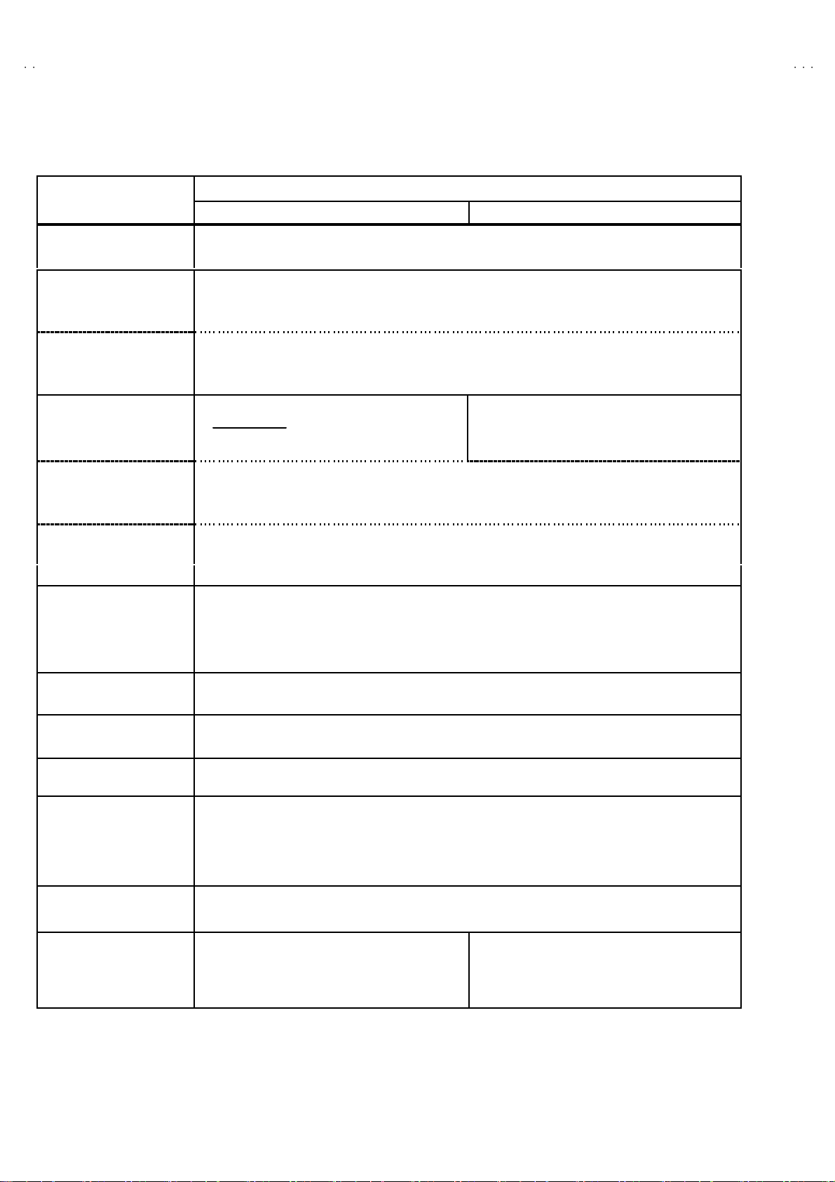
SPECIFICATIONS
Item
Dimensions ( W××××H××××D ) 85 4m m× 5 07.5mm×493. 5mm
Mass 43 .0 kg
TV RF System CCIR ( I )
Colour Syst em PA L
Stere o Sy st em NICAM
Teletext System FLOF (Fastext)
Receiving Frequency
VHF 47 MHz ~ 47 0MHz
UHF 47 0MHz ~ 862MHz 470MHz ~ 862MHz
Intermediate Fr equency
VIF Carrier 38.9MHz ( I )
SIF Car rier 32 .9 MHz ( 6 .0MHz:I )
Colour Sub Carrier Freq.
PAL 4.43MHz
NT S C 3.58MHz / 4.43MHz
Power Input AC 2 20V ~240V , 50Hz
Power Consumption 18 0W ( Ma x) / 1 20W( Av g)
Aerial Input Term 75Ωun ba l anc ed, C oaxial
Pictur e Tube Visi bl e size : 66cm , M easured di a gonal l y
Hi gh Vo l t ag e 31.0kV (at zero beam current)
Speake r
Au dio Output 10 W + 10W
EX T-1/EXT - 2/ EXT-3
(Input / Output)
EXT-4 (Input) Video
Au di o (L /R )
S / Vide o
AUDIO OUT (Vari able) 0~1Vrm s , Low Im p ed ance (RCA pin jack×2)
Headphone jack St ereo min i jac k (φ3.5mm )
Remote Control Unit
AV28 T25 EK S / AV28T 25E KB / AV2 8T 55 EKS AV28 T25 EIS
NTSC (Only in EXT mode)
WST(Standard system)
St andby : 3W
1kV
+
-1. 5kV
6.5 cm×13cm Oval type ×2
21 -p i n E uro c onnec to r
(SCART socket)
1V p- p 7 5Ω(RCA pi n ja c k)
50 0m Vr ms( -4dB s ), H i gh Im pe dance ( RCA pin jack )
p-p
Y : 1V
C : 0 .28 6V
RM-C 55H-1 C(AV 28T2 5EKS/ AV28T5 5EKS)
(AAA/ R03 dry b atte ry ×2)
RM-C 51 -1 C ( AV 28 T 25E KB)
(AAA/ R03 dry b atte ry ×2)
POSITIVE (Negative sync Provided, when terminated with 75Ω)
p-p
(Burst signal, when terminated with 75Ω)
Content
RM-C 55 H- 1 C ( A AA/R0 3 dr y bat tery×2)
De sign & speci f icatio ns ar e su bje ct to cha ng e wi thout no t ice.
2
No.51942
Page 3
A
V28T25EK
S
A
B
A
S
A
V28T25EK
V28T55EK
V28T25EIS
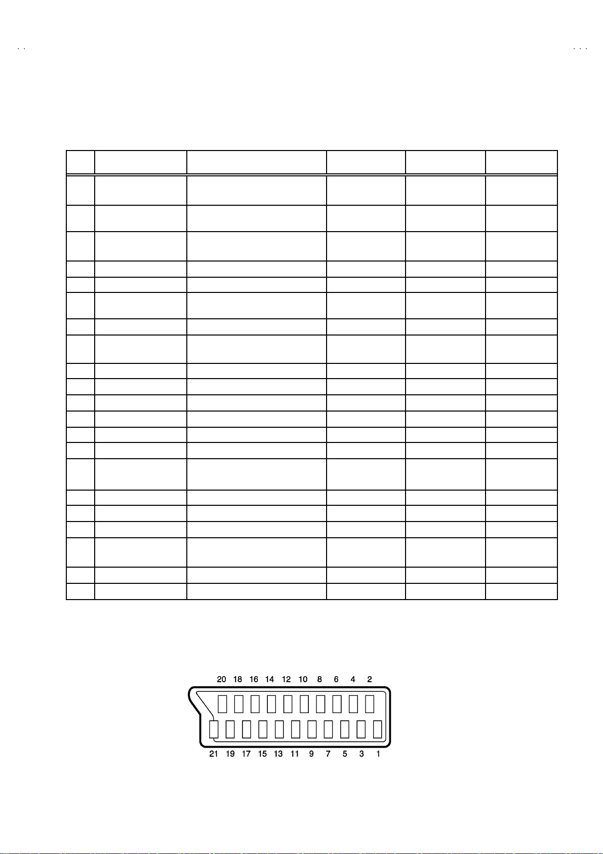
■■■■21-pin Euro connector (SCART socket) : EXT-1 / EXT-2 / EXT-3
(P-P= Peak to Peak, S-W= Sync tip to white peak, B-W= Blanking to white peak)
Pin
Signal Designation Matching Value EXT-1 EXT-2 EXT-3
No .
1 AUDIO R o utput 50 0m Vr ms(Nomina l) ,
Low impedance
2 AUDIO R i n put 50 0m Vr ms(Nomina l) ,
High i m pe danc e
3 AUDIO L outp ut 50 0m Vr ms(Nomina l),
Low impedance
4 AUDIO G ND ○○○
5 GND (B)
6 AUDIO L input 500mVrms(Nominal),
High i m pe danc e
7B input 700mV
8 FUNCTON SW
(SLOW SW)
9 GND (G)
10 SCL3 NC ○ NC
11 G in put 70 0m V
12 SDA3 NC ○ NC
13 GND (R)
14 GND (YS) ○ NC NC
15 R / C input R : 700mV
16 Ys i n put
17 GND(VIDEO output) ○○○
18 GND(VIDEO input) ○○○
19 VID EO outpu t 1V
20 VIDEO / Y inp ut 1V
21 COMMON G ND ○○○
Low : 0-3V, High : 8-12V, High
impedance
C : 300mV
Low : 0 - 0.4, High : 1 - 3V, 75Ω○
, 75Ω○NC NC
B- W
, 75Ω○NC NC
B- W
, 75Ω
B-W
, 75Ω
P- P
(Nega ti ve g oi n g s ync ), 75Ω○
P- P
(Nega ti ve g oi n g s ync ), 75Ω○ ○ ○
P- P
○
(TV OUT)
○○○
○
(TV OUT)
○○○
○○○
○○○
○○○
○○○
○
(only R)
(TV)
○
(LINE OUT)
○
(LINE OUT)
○
(only C )
NC NC
○
(LINE OUT)
NC
NC
○
(only C )
NC
[Pin assignment]
No.51942
3
Page 4

A
V28T25EKS
A
A
A
V28T25EKB
V28T55EKS
V28T25EIS
SAFETY PRECAUTIONS
1. The des i gn of this pr o du ct c ont ai ns spe cial har d ware and many
circuit s and components specially for saf ety purposes. For
con tinu ed pr ot ecti on , n o chan g es sh ould b e ma de to the o rig i nal
d esign un less a uth or ized in writi n g by th e manu fac t urer .
Replacem ent p arts m ust b e i d entic al to thos e u sed in th e or i gi n al
ci rcu its. S er v i ce sho ul d b e p er for m ed by qu alif ied p ers on nel
on ly.
2. Alte r ation s of the desi g n or circ uitr y of th e pr oduct s ho ul d not be
made. Any design alterations or additions will void the
manu fac t urer 's warra nt y and will f urth er r el i eve t he ma nufac tu rer
of r esp onsib ili ty for per s o na l injury or pr operty d am ag e res ul t ing
th erefr om.
3. Man y electric al a nd me chanical p arts in the prod uct h ave spe cial
saf ety- r el at ed ch ar act er ist i cs. Thes e ch aracter istics a re oft en not
evi d ent fr om visu al insp ectio n no r c an th e pr otect ion af for ded by
th em n ec ess ar y b e o bta in ed by using r e plac em ent c ompon en ts
rate d for high er volta ge, watta ge , etc. R e pl ac em en t p art s whic h
WARNING
h ave th ese spe cial saf et y c har ac teristic s ar e i d ent if i ed i n th e
Pa rts List of S er vice Ma nual. El ectr ical co mp on en ts hav i ng suc h
fe atures are i de ntifi ed by sh adin g on th e s che ma tic s a nd by (!)
on t he P arts Li st i n the S er vice M an ual. The u se of a s ub s ti tut e
replac ement w hich d oes no t h av e th e s am e saf ety
ch arac ter i s ti cs as the re commend ed r epl ac e m ent p ar t sho wn i n
th e Par ts Li s t of Se rvi ce M an ual m ay cau se shock , f ire, or ot her
hazards.
4. The l ea ds in th e p r odu c ts ar e r ou ted an d d ress ed w it h t ies,
cl am ps, tu bing ’s , b arrie rs a nd t he lik e t o be s epa ra ted from live
p arts, h ig h t empe ra ture parts, movi ng parts an d / or sh ar p ed ge s
for t he preven tion of e lec tr i c sh ock and fire h azard. W hen
ser v ice i s r e qu ir ed , the or i gi n al l e ad r outi n g and dre s s sh ould b e
ob served , and it sh oul d b e c o nfirmed t hat th ey h av e b ee n
retu rn ed to no rmal, aft er r e- asse mblin g.
1. The equi pm ent h as b ee n d esig ned a nd m anufac t ured to me et i nte rn ati o nal saf ety sta nd ar ds .
2. It i s t he l eg al r es p ons ib ility o f th e re pairer t o ensure th at t hes e s afet y stan da r ds are mai nt aine d.
3. Rep airs mu s t b e mad e i n acc ordan ce with th e r ele vant saf ety st an dards .
4. It i s essen tial t hat saf ety cr iti cal c omp on ents ar e repl ac ed by a ppro ved pa rt s.
5. If mai n s volt age selec tor i s p r ovide d, c h ec k s ettin g for loca l voltag e.
4
No.51942
Page 5
A
S
A
B
A
S
A
FEATURES
V28T25EK
V28T25EK
V28T55EK
V28T25EIS
"
By pr ef erenc e, us er s can sel e ct the pic tur e si ze fr om REG ULAR ,
PANORAMIC, FULL, 14 :9 ZOOM, 16:9 ZOO M, 16:9 ZOOM SUB
TITL E mod es. W he n the T V u nit r e ceiv ed W SS pict ur e s i gn al , th e
pictu re ca n be changed t o 1 6:9 ZOOM mode au tomat ic ally.
" The TELE TEXT S YSTE M has a b uilt - i n FAS T EXT, and W ST
system.
" Be caus e th is TV un i t cor r esp on ds t o mul tipl e x br oa dca s t, u ser s
can enjoy music programs and sporting events with live realism.
In ad dition , BI LIN GU AL pro gr am s can be h ear d in th ei r or i g in al
language.
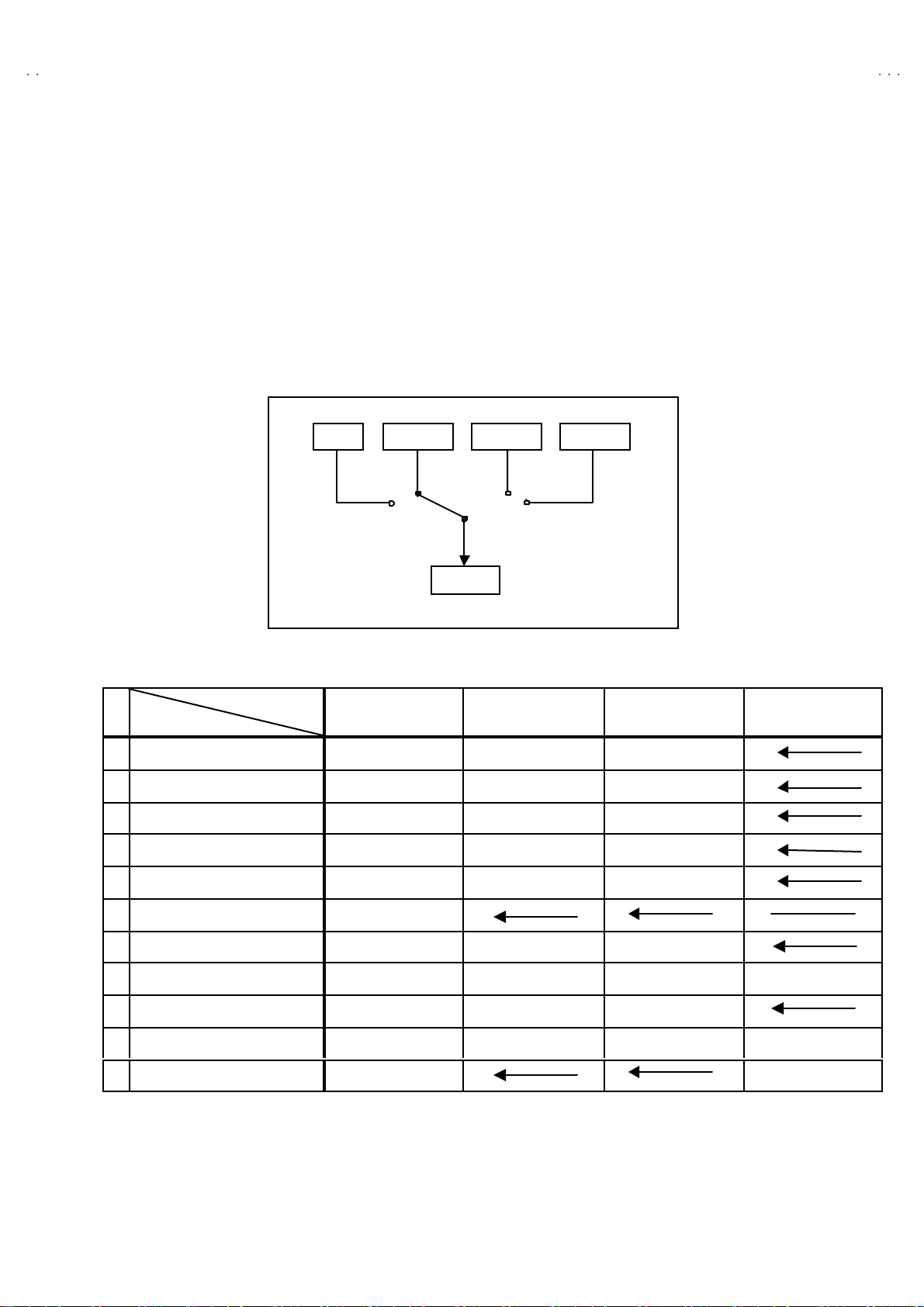
TV EXT-1 EXT-3
EXT-2
"
Users can make VCR dubbing of picture and sound by controlling
th e AV sel ec tor to s e le c t an o pti o na l so urc e at th e EXT- 2 outp ut
sh own i n figu re.
EXT-4
MAIN DIFFERENCE LIST
Model Name
!!!!
Part Na me
!
F.CABI ASSY LC11313-002B-U LC11313-005B-U
!
REAR COVER LC11282-001C- U LC11282-002C-U
!
AV BOARD LC11010-004A-U LC11010-005A-U
JVC MARK LC41250-002C-U LC41250-003C-U
RC HAND UN IT RM-C5 5H-1C RM-C5 1-1C
REG CARD AEM3148-001-E
CENTER PANEL LC2 1065-001A-U LC21065-002A-U
!
RATING LABEL LC11364-003A-U LC11364-013A-U
!
POWER KNOB LC31201-003A-U LC31201-006A-U
EURO LABEL AEM1064-003-E AEM1064-025-E AEM1064-024-E
MAIN PWB SJL-1002A-U2
AV28 T2 5E KS AV28T25E KB
AV28 T5 5E KS AV28 T2 5E I S
LC11313-002B-U
LC11282-001C- U
LC11010-004A-U
LC41250-002C-U
RM-C5 5H-1C
LC21065-001A-U
LC11364-012A-U LC11364-016A-U
LC31201-003A-U
AEM1064-005-E
SJL-1006A-U2
No.51942
5
Page 6
A
V28T25EKS
A
A
A
V28T25EKB
V28T55EKS
V28T25EIS
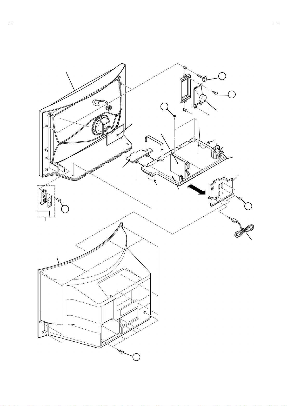
SPECIFIC SERVICE INSTRUCTIONS
DISASSEMBLY PROCEDURE
REMOVING THE REAR COVER
1. Unp lug t he po we r c ord.
2. Remove the 13 screws marke d A as s hown in t he Fig. 1.
3. W ithdr a w t he r ear c o ver to wa rd y ou .
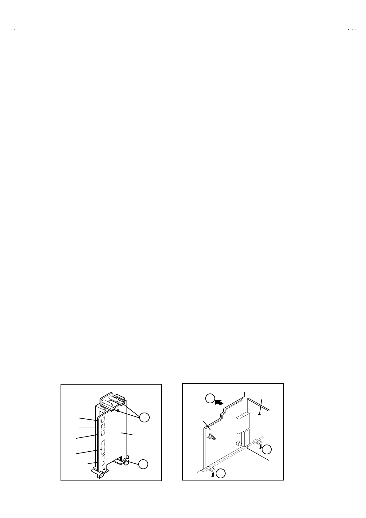
REMOVING THE SIDE CONTROL JACK ASSEMBLY
" After removing the rear cover.
1. Remove the screw marked B as s h ow n i n the F i g.1 .
2. Whil e slight ly rai se th e sid e c ontro l jack ass e mb ly, r em ove th e 2
claws under the side control jack assembly.
3. Disc onn ect th e c onnecto r “SR ”, “ SL”, “ S”, “F” and “CN016” as
shown in Fig 2.
REMOVING THE SIDE CONTROL PWB
"
Af ter removi ng the r ear cover an d sid e co ntr ol j ac k ass embly.
1. Rem ov e th e 3 claws C from back side of the side control ja ck
asse mb l y as s hown in Fig. 2.
2. Pu ll out the SI DE C ON TROL PW B.
REMOVING THE CHASSIS
" After removing the rear cover.
1. Sli ght ly rai se th e bo th si de s of th e c hassi s by h and and re mo ve
th e two c l aws u nd er th e b oth sid es of the chass i s fr om t he fro nt
cab inet .
2. W ithdr a w t he chass is backw a rd .
(If necessary, take off the wire clamp, co nnectors etc.)
REMOVING THE POWER & DEF. PWB
"
After removing the CHASSIS.
1. Remove the 3 scr ew s marked H a s s h own in the Fig.1 .
2. R em ove the PO W ER & DEF. PWB up w ard.
REMOVING THE SPEAKER
"
After removing the rear cover.
1. Remove the 2 scr ew s marked D, and rem ove th e speake r hol d er
as s hown in Fi g. 1.
NOTE : W hen r emov i ng t he scr ew s m ar ked D of t he sp eak e r
remove t he lo w er side sc r ew fi r s t, an d t hen remove th e
up per one .
2. Remove the 2 screws E attac hing th e sp eaker.
3. Fol l ow th e s am e st eps wh en rem oving th e oth er ha nd spe ake r.
REMOVING THE AV TERMINAL BOARD
"
After removing the rear cover.
1. Remove the 3 scr ew s marked F as sh own i n t he Fig . 1.
2. Remove the 2 claw s m ar ked G under the CHASSIS as shown in
Fig. 3.
3. Remove the AV TERMINAL BOARD slightly in the direction of
arrow X as shown in Fig. 3.
CHECKIN G THE PW BOARD
To c h ec k the back s i de of th e PW B oard.
1) Pull out the ch assis . ( Refer to RE MOV ING THE CHASSIS).
2) Erect the c hassis vertically so that you c an easily check the
b ack side of the PW B oard.
[CAUTION]
"
When erecting the chassis, be careful so that the re will be no
contacting with other PW Board.
"
Be fore tur n ing on po wer, ma ke sur e tha t the wire co nnecto r is
prop er l y con nected .
"
W hen co ndu cti ng a c h ec k wi th p ow er su pplied , b e sure to c onfir m
th at t he CRT E AR T H WI RE (B RAIDED AS S’Y) is co nne c ted t o
th e C R T SOC KE T PW b oard.
6
Connector
SR
SL
S
F
CN016
Fig . 2
C
SI DE
C ONT RO L
PWB
C
(Back view)
WIRE CLAMPIN G AND CABLE T Y ING
1. Be sure t o clamp th e wir e.
2. Never r em o ve th e c able tie use d f or tying th e wires to ge the r.
No.51942
Sh oul d it be i n adv e rt ent l y rem ove d, b e su r e to tie th e wires w it h
a n ew c able tie.
X
AV TERMINAL
BOARD
AV SW PWB
G
G
Fig . 3
Page 7
A
S
A
B
A
S
A
FRONT CABINET
(
)
(×3)
(×2)
(
)
V28T25EK
V28T25EK
V28T55EK
V28T25EIS
D
E
×
2
Fig.2
SI DE C ONT R O L
JACK ASSEMBLY
H (×3)
FRONT
C ONT RO L
PWB
CRT
SOCKET
PWB
C ONT RO L
BASE
AV SW
PWB
CLAW
MAIN
PWB
POWER & DEF.
PWB
B
SI DE
SP EAKER
CLAW
CHASSIS
AV TERMINAL
BOARD
F
POWER CORD
REAR COVER
A
×
13
Fig . 1
No.51942
7
Page 8
A
V28T25EKS
A
A
A
V28T25EKB
V28T55EKS
V28T25EIS
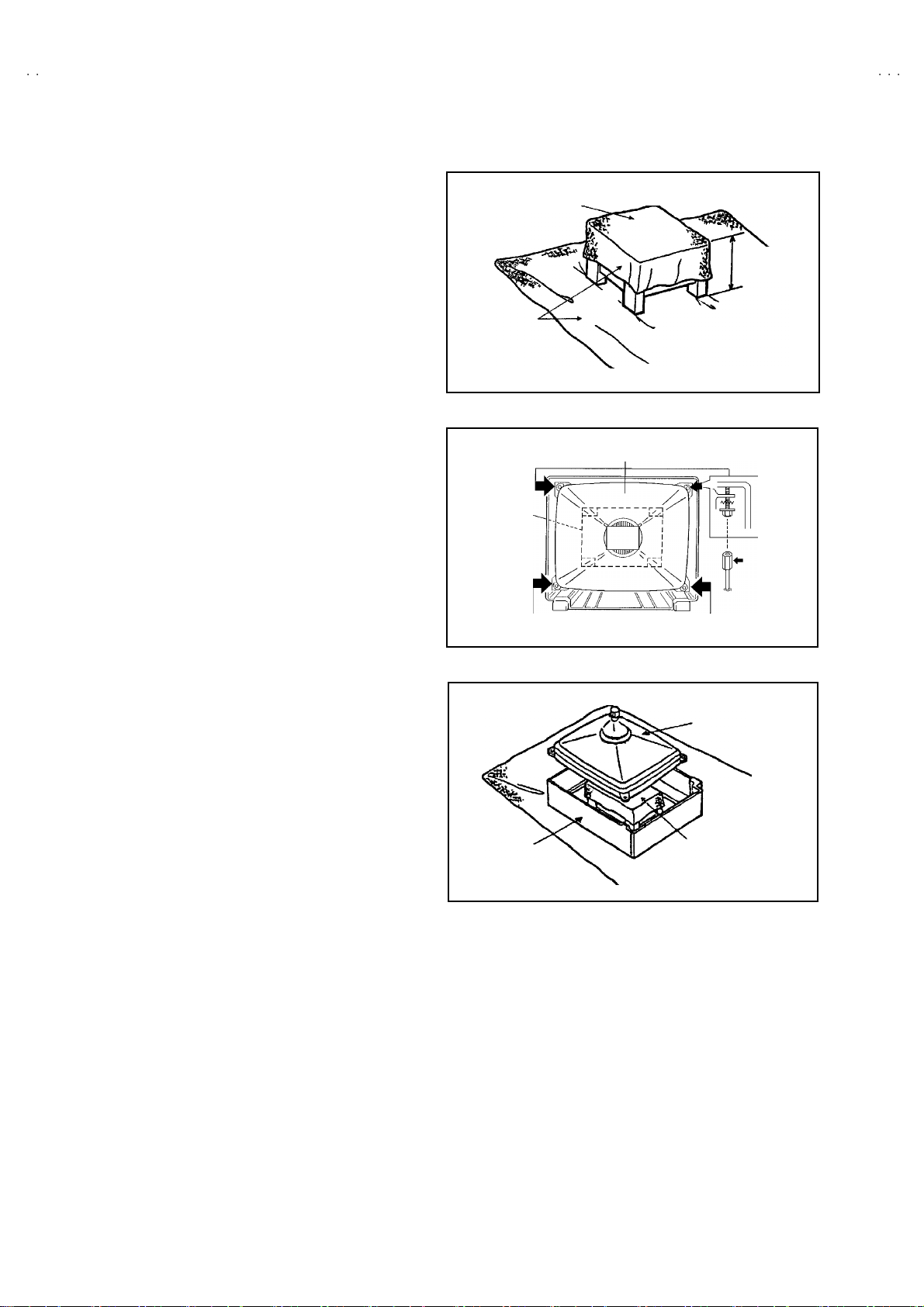
REMOVING THE CRT
∗
Replacem en t of th e CRT s ho ul d be p er for m ed b y 2 or mor e
p ers ons.
• After removing the c over, chassis etc.,
1. Pu tti ng the CRT c han ge table o n sof t cl oth , th e C R T cha nge ta ble
sh ould al so b e c over e d w i th s uch soft clot h (s ho wn i n Fig. 4) .
2. W hile kee pin g the s urfac e of C RT dow n , mou nt the TV s et o n t he
CRT chan ge table balanced will as shown in Fig.5.
3. R em ov e 4 sc rews mark e d by arro ws with a box ty p e s crew d rive r
as s hown in Fig. 5.
• Si nc e th e c ab i net wi ll drop wh en s crews h ave b een remo ved, be
sure t o su pp ort t he cabinet with hands.
4. After 4 screws have been removed, put the cabinet slowly on
cloth (At th is time, be ca refully so as not to damage th e front
sur fac e of th e c abin et) s h ow n i n Fig.6 .
• The CRT sh ould b e ass embled accor di n g to th e o pp osi te
sequence of its dismounting steps.
∗
The C RT cha ng e t able sh ould pr ef erab ly b e smaller that th e CRT
sur fac e, and its h ei gh t be abo ut 35c m.
CRT CHANGE TABLE
AP PROX.
35 cm
CLOTH
Fig. 4
CRT
CRT
CHANGE
TABLE
BOX
TYPE
SCREW
DRI VER
CABINET
Fig. 5
CRT
CRT
CHANGE TABLE
Fig. 6
8
No. 51942
Page 9
A
S
A
B
A
S
A
REPLACEMENT OF MEMORY ICs
1. Memory ICs
This TV use memory ICs. In the memory ICs, there are memorized data
for correctly op er atin g th e video an d def l ection circ u its . Wh en r ep lac i ng
memory ICs, be s ure t o us e IC s wr itte n with the i ni tial values of da ta.
2. Procedure for replacin g memory ICs
PROCEDURE
(1) Power off
Switch the p ow er of f and un plug th e pow er cor d f ro m t he ou tlet.
V28T25EK
V28T25EK
V28T55EK
V28T25EIS
(2) R epla ce ICs.
Be sure to use memory ICs written with the initial data values.
(3) Powe r o n
Plug th e pow er c ord int o th e outl et a nd s wit ch t he powe r on .
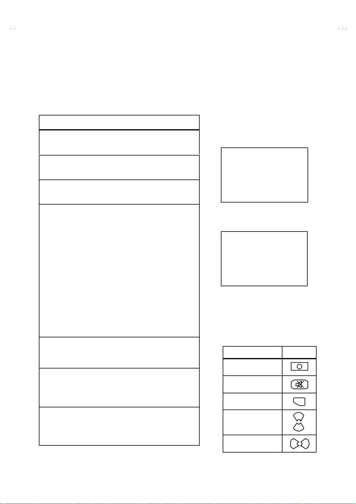
(4) Check and s et SY STEM CO NSTA NT SET :
It must not adjust witho ut signal.
****
1) Pr es s th e INFO RMATI ON ke y and the MUT ING key of th e
REMO TE CONTROL UNIT simultaneous ly.
2) The SERVICE MENU screen of Fig. 1 will be displayed.
3) While th e S ERVIC E MENU is displ a yed, pr ess t he
INFORMATION key and MUTING key s imultaneously, and the
SYSTEM CONSTANT SET screen of Fig. 2 will be displayed.
4) Check th e se tting va lues of the S YST EM C ONSTA NT SET of
Table 1. If the valu e is dif fere nt, sel ect th e s etting item with th e
FUNCTION UP/ DOWN ke y, and s et the corr ect va lue with th e
FUNCTION -/+ ke y.
5) Press the MENU key to memorize the setting value.
6) Pres s t he INFORMATION ke y t wice, a nd r etu rn t o th e no rmal
screen.
SE RVIC E ME N U
1. IF 2. V/C
3. AUDIO 4. DEF
5. VS M PRES ET 6. VP S
7. SHIPPING (OFF)
1- 7 : SEL ECT i : EXIT
Fig.1
SY STEM C O NS TAN T S ET
MODEL=JL_EURO(
1. DESTINATION : EK
JVC JL E URO V00
*** ****
- + OK: STORE i : EXIT
*.*** *
Fig.2
)
(5) Se tt in g of re ceive chann e ls
Se t th e r ec eiv e ch anne l.
NAME OF REMOTE CONTROL KEY
Names of key
key
For setting , r ef er to the OPE RATING INS TRUCTIONS.
INFORMATION
iiii
(6) U ser se tting s
Check th e us er s ett ing values of T ab le 2, and if sett in g value is
MUTI NG
diff erent , set th e c orrec t val u e.
For setting , r ef er to the OPE RATING INS TRUCTIONS.
OK
▼
▼
(7) Setting of SERVICE MENU
Ve rif y the set ting it ems of the SE R VICE ME NU of Tab l e 3, and rese t
where n ecessary.
MENU
FUNCTION UP/DOWN
For setting , r ef er to the SE RVIC E ADJUSTMENTS.
▼
FUNCTION -/ +
No. 51942
▼
9
Page 10

A
V28T25EKS
A
A
A
V28T25EKB
V28T55EKS
V28T25EIS
SETT ING VALU ES OF SYST EM CO NS TANT SE T (TABLE 1)
Setting ite m Setting content Setting value Setting item Setting content Setting value
AV 28T2 5EKS
EK EPEI
2.DOLBY YES NO NO 7.FLAT YES NO YES
3.BBE YES NO NO 8.3-D YES NO NO
AV 28T2 5EKB
AV 28T5 5EKS
EK EI 6.PICT UR TI LT YE S NO NO
AV 28T2 5EIS
4.TV SPE AKER YE S NO NO
5.COMB YES NO NO1.DESTINATION
USER SETTING VALUES (TABLE 2)
Setting ite m Initial setting value Se tting item Initial setting value
SOUND LEVEL 10 SUB POWER ON
SHIPPING CHANNEL 1 ZOOM MODE PANORAMIC
USER M ENU SE TT ING
PICTURE SE TTING EX T SETTI NG
TINT
CONTRAST
BRIGHT
SHAR P
COLOUR
AUT O VNR
COLOUR S YST E M
4:3 AUTO ASPECT
STEREO /
BA SS
TR EBL E
BALANCE
BB E
HYPE R S OU ND
SP EAKE R
Ⅰ・Ⅱ
COOL
REFER to VSM PRESET
PICTURE FEATURES FEATURES
AUT O
TV : Ac co rd ing t o pr eset CH
EXT : AUTO
PA NO RA MI C
SOUND SET TING INSTALL
CENTER
CENTER
CENTER
ON
OFF
ON
DUB BIN G EXT-1→EXT-2
SLEEP TIMER
BLUE BA CK
CHILD LO CK
DECODER (EXT-2)
LA NG UA G E
EDIT/MANUAL
DEMO OFF
OFF
ON
ID : No.****
ALL CH OF F
OFF
ENGL ISH
PRES ET CH on ly
The others : BLA NK
SERVICE MENU SETTING ITEMS (TABLE 3)
Setting item Setting value Setting item Setting value
1. IF VCO
2. V / C 1. CUT OFF
3. AUDIO
(Do not a dju st)
2. DRI VE
3. BRIGHT
4. CONT.
5. COLO UR
6. HUE
7. BLAC K O FFS ET (Onl y SE C AM )
8. SHAR P
1. ERROR LIMIT
2. A2 ID THR
3. BA SS
4. TR EBL E
4. DEF. 1. V-SHIFT
5. VS M PRESE T
COOL
NORMA L
WARM
6. VP S
(Do not a dju st)
7. SH IPP IN G
(Do not a dju st)
2. V-SIZE
3. SUBT IT LE
4. H-CENT
5. H-S IZ E
6. EW - PIN
7. TR APE Z
8. EW. COR. L
9. EW. COR. H
10. V. S- C OR
11 . V- LIN
12. H-BL K-R
13. H-BL K-L
14. V-EHT
15 . H - EH T
16. EHT- GAIN
1. BRIGHT
2. CONT.
3. COLO UR
4. SHAR P
5. HUE
6. R DRIVE
7. B DRIVE
VP S
PDC
WSS
ON / O FF
10
No. 51942
Page 11

A
S
A
B
A
S
A
REPLACEMENT OF CHIP COMPONENT
! CAUTIONS
1. Avoid heating for more than 3 seconds.
2. Do n ot ru b the elect ro des an d the r esis t p arts of the p att ern.
3. W hen r em ov i ng a c hip part, mel t th e s older ad equate ly.
4. Do n ot reuse a chip p ar t afte r re mo v ing it .
! SOLDERING IRON
1. Use a hig h i ns ulati o n s ol der ing i r on with a thi n poin ted end of it .
2. A 3 0 w s older i ng i r on is rec omm end ed for easily r em oving p arts.
!
REPLACEMENT STEPS
1. How to remove Chip parts
####
Resi st o rs, ca pacitors , etc
(1) As sh own in the f ig ur e, pu sh th e pa rt w ith tw ee zer s and
alte rn at ely melt the s ol de r at eac h end.
(2) Sh if t with tweeze rs and r em ove th e c h i p p art.
#### T rans isto rs, d io d es , va ria bl e r esist or s, etc
(1) Ap pl y e xt ra so ld er to eac h le ad .
SOLDE R SOLD E R
V28T25EK
V28T25EK
V28T55EK
V28T25EIS
2. How to install Chip parts
####
Resi st o rs, ca pacit o rs , et c
(1) Apply sold er to the pattern as indic ate d in the figure.
(2) Gr asp the c h i p p art with tw ee zer s and pl ac e it on th e s old er.
The n hea t and me lt th e so lder a t both ends of t he chi p part.
#### Trans isto rs, d io d es , va ria bl e r esist or s, etc
(1) Apply sold er to the pattern as indic ate d in the figure.
(2) Gr asp th e ch ip p art wit h t we ezers an d pl ac e it on th e so l der .
(3) First solder lead A as indicated i n t he figu re.
A
(2) As sh own in the f ig ur e, pu sh th e pa rt w ith tw ee zer s and
alte rn at ely melt th e sol d er at each le ad . S hi ft an d r em ove the
chip part.
(4) The n so lder le ads B and C .
Note : A fte r re moving t he part, r emove rem ain ing solder fr o m the
pattern.
C
A
C
No.51942
B
B
11
Page 12

A
V28T25EKS
A
A
A
V28T25EKB
V28T55EKS
V28T25EIS
SERVICE ADJUSTMENTS
BEFORE STARTING SERVICE ADJUSTMENT
1. There ar e 2 w ays of ad ju st in g this TV: One is wi th the
REMOTE CONTROL UNI T and the other is the conventional
method using adjustment parts and components.
2. The setting (adjustment) using the REMOTE CONTROL
UNIT is made on the ba sis of th e initial se tting values . Th e
se tting va lu es whic h adjust the sc ree n to the o p t imum
condition can be different from the initial setting values.
3. M ak e s ure th at conn ect i on i s c orrect l y ma de t o AC p ower
source.
4. T ur n on th e powe r of th e TV a nd m easu r in g i nstr um en t for
warmin g up f or at least 30 min ut es bef ore sta rt in g adju stm ent .
5. If th e r ec ei ve or i np ut sig nal is not sp eci fi ed , use t he m ost
ap pr op ri a te s ig na l f or a dj ust me nt.
6. Never tou ch p ar ts ( such as variab le r esist or s , tran sfor m er s an d
condensers) not shown in the adjustment items of this service
adjustment.
7. Pr ep ar ation f or ad j ustm en t (pr es etti n g) :
Unles s oth erw is e sp eci fi ed in th e a dj us t ment it em s , p res e t th e
follo win g fu nct ions with th e REMOTE CONTROL UNIT:
" Setting positi on
PICTURE MO DE (VSM) NO RMAL
SLEEP TIMER OFF
BALANCE CENTER
ZOOM PANORAMIC
MEASURING INSTRUMENT AND FIXTURES
1. DC voltmeter (or digital voltmeter)
2. Oscilloscope
3. Sign al g en erat or (P att er n g ener at or) [ PAL / N TSC]
4. Remote control unit
ADJUSTMENT ITEMS
●
B1 POW E R SUPPL Y check.
●
HIGH VOLTAGE check.
●
FOCUS Adjustment.
●
IF ci rcuit a djust ment.
●
VS M p r es et adju st s etti n g.
●
VIDEO / CHROMA circuit adjustment.
●
DEFLECTION c ircuit adjustment.
●
H BLA N KING adj us tment.
●
AUDIO circuit adjustment. (Do not adjust)
12
No. 51942
Page 13

A
S
A
B
A
S
A
ADJUSTMENT LOCATIONS
CN009
CN008
3p
C
CN009
S
V28T25EK
V28T25EK
V28T55EK
V28T25EIS
FRONT
FRONT CON TROL PWB (1/2)
REMOCONLED
PO W E R
SW
FUSE
PW
W
CN001
FRONT
MAIN PWB POWER&DEF PWB
CN001
CN016
CN00S
CN0SC
CN0SW
AV SW PWB
CN8102
IC701
IC702
ME MORY
FRONT
W
FRONT CON TROL PWB (2/2)
S
F
VLRHP
SL
DEG
CN8102
UP
DOWN
R
FRONT
CN006
TUNER
F
CRT SOCKE T PWB
TP-47R
TP-47G
TP -E
IC301
CN008
(SOLDER S IDE)
TP-47B
E1
TOP
HV
FO CUS
SCREEN
X
1
5
1pin :B 1(TP-91)
2pin :N C
in :N
4pin :N C
5p in :GN D(T P- E)
No. 51942
13
Page 14

A
V28T25EKS
A
A
A
y
y
V28T25EKB
V28T55EKS
V28T25EIS
BASIC OPERATION SERVICE MENU
1. TOOL OF SERVICE MENU OPERATION
Operate the SERVICE MENU with the REMOTE CONTROL UNIT.
2. SE RVICE MENU ITEMS
With the SERVI CE MENU, var i ou s sett ings ( ad ju s tm en ts) c an b e m ade , a nd th ey are b r oad ly classif i ed i n th e f ol lowing ite ms of set tings
(adjus tments ):
(1) 1. IF ・・・・・・・・・・・・・・・・・・・・ ・・・ This mod e adjust s the se tting valu es o f th e IF circui t.
(2) 2.V /C ・・・・・・・ ・・・・・・・・・・・・・ ・・ This mod e adjust s the se tti ng valu es o f th e VIDEO / CHROMA circu it.
(3) 3.AUDIO・・・・・・・ ・・・・・・・・・・・・ This mode adjusts the setting values of the multiplicity SOUND circuit. (Do not adjust)
(4) 4. DEF ・・・・・・・ ・・・・・・・・・・・・・・ T his m ode adjust s th e setti ng valu es o f th e DE FLECTION ci r cuit f or eac h as pect m od e gi ven be lo w .
REGU LA R (50/ 60Hz)
PA NO RA MI C ( 50/ 60 Hz)
14 :9 Z O OM (50/ 60 Hz)
16 :9 Z O OM (50/ 60 Hz)
16 :9 S UB T IT L E (50/ 60 Hz)
FU LL ( 50/ 60Hz)
(5) 5.V SM PR ESE T ・・・・・・・ ・・・・・・ Thi s m od e adjust s th e in itia l s ett ing values of COOL, NORM AL and W AR M .
(VS M : V ide o Sta tus Mem or y)
(6) 6.V PS ・・・・・・・ ・・・・・・・・・・・・・・ T his m ode sh ow s th e mo nitor of t he VP S, PDC a nd WSS . (Do not adjust)
(VP S : Video Program Syst em, PDC : Program Delive ry Code, W SS : W ide Scree n Sig na lling )
(7) 7.SHIP PING ・・・・・・・ ・・・・・・・・・ This men u is s et a t sh ipping. (Do not adjust)
3. BASIC OPERATION OF SERVICE MENU
(1) Ho w to enter SERVICE MENU
Press the INFORMATION key and the MUTING key of t he
REMO TE CON TRO L U NI T simu lt aneou sly, an d th e
SERVICE MENU screen of Fig. 1 will be displayed.
(2) Selection of SUB MENU SCREEN
Press one of keys 1~7 of the REMOTE CONTROL UNIT
an d sele ct th e S UB MENU SCREEN (See F i g. 3 ), fo rm the
SERVICE MENU.
SERVICE MENU → SUB ME NU
1. IF
2. V / C
3. AUDIO
4. DEF.
5. VSM PRE SET
6. VP S
7. SHI PPING
SE RVICE MENU
SE R VIC E ME NU
1. IF 2. V/C
3. AUDIO 4. DEF
5. VSM PRESET 6. VPS
7. SHIPPING (OFF)
1-7 : SELECT i
NEME OF REMOTE CONTOROL KEY
Names of ke
INFORMATION
MUTI NG
MENU
FUNCTION UP/DOWN
FUNCTION -/ +
Fig.1
Fig.2
: EXI T
ke
i
i
OK
▼
▼
▼
▼
14
No. 51942
Page 15

A
S
A
B
A
S
A
SERVICE MENU
SERVIC E MENU
1. IF 2. V/C
3. AUDIO 4. DEF
5. VSM PRESET 6. VPS
7. SHPIING (OFF)
1-7 : SELECT i : EXIT
7. SHIPPING
7. SHI PPING( OFF)
7. SHI PPING ( ON)
V28T25EK
V28T25EK
V28T55EK
V28T25EIS
Do not ad just
COOL
NOR MAL
WAR M
1. BR IGHT
2. CONT .
3. COL OU R
4. SHA RP
5. HU E
6. R DR IV E
7. B DR IV E
Do not ad just
5. VSM PRESET
VSM PRESET NORM AL
1. BR IGHT
- + OK : STORE i : E XIT
VPS = 0 000H(- - -)
PD C 8 / 30 / 1 = 0 000 H
WSS = 0 000
***
6. VPS
VPS
= 0 000 H
i : E XIT
1.IF (VCO)
VCO (CW)
TOO HIGH
ABOVE REFER ENCE
JUST REFE RENCE
BEL OW R EFE RE NC E
TOO LOW
V/C
1. CUT OFF (R)
- + OK : STORE i : E XIT
**
** ....**
****
2. V/ C
PAL
**
****
(G)
(B)
MHz
****
****
****
i: EXIT
1. CUT OFF
2. DR IVE
3. BR IGHT
4. CONT .
5. COL OU R
6. HU E
7. BLAC K OFFS ET
8. SHARP (Do not ad just)
3. AU DI O
AU DIO
1. ERR OR LIM IT = 100H
ERROR RATE = 7F0H
C_ AD_BI TS = 00 000 000
- + OK : STORE i : E XIT
4. DEF
DEF PANORAMIC
1. V- SHIFT
- + OK : STORE i : E XIT
Fig. 3 S UB MENU SCREEN
***
(**)
Do not ad just
1. ERROR LIMIT
2. A2 ID THR
3. BA SS
4. TREBLE
1. V-SHIFT
2. V-SIZE
3. SUBTITLE
4. H-C E NT
5. H-SI Z E
Hz
**
**
****
6. EW -P IN
7. TRAPEZ
8. EW.COR.L
9. EW.COR.H
10. V.S-COR
11 . V-L I N
12 . H -BL K- R
13 . H -BL K- L
14 . V-EHT(Do not adjust)
15 . H -E HT (Do not ad jus t)
16 . EH T-G A IN (D o no t ad jus t )
No. 51942
15
Page 16

A
V28T25EKS
A
A
A
V28T25EKB
V28T55EKS
V28T25EIS
(3) Method of Setting
1) M eth od of Set ting 1. IF
[VCO]
① 1 K ey・・・・・・・ ・・・・・・・・・・・・・ ・・・・・ Select 1 .IF.
② The VCO (CW) screen will be displayed in yellow when the AFC voltage is at a certain level and in blue when it is at other levels.
③ IN FOR MATION K ey ・・・・・・・ ・・・・・ Retu rn t o the SER VICE MENU screen.
2) Meth od of s ett in g 2.V/C, 3.AUDI O, 4.DEF and 5.VSM PR ESET.
① 2 ~5 K ey・・・・・・・ ・・・・・・・・・・・・・ ・・ Select one from 2.V/C, 3.AUDIO, 4.DEF and 5.VSM PR ESET.
② F UNCTION U P / DOWN Key ・・・・ Se lect s etting items.
③ F UNCTION - /+・・・・・・・ ・・・・・・・・・・ Set ( ad just) th e se tting values of the settin g it ems.
(U se th e num ber keys of th e REMOTE CONTROL UNI T for s etting of WHITE BALANCE.
For the s etti n g, ref er to eac h i t em concer ned.)
④ ME NU Key ・・・・・・・・・・・・・・・・・・・・ M emorize the s etting va lue.
(Bef ore st orin g t he s ett in g valu es in me mo r y, do no t pres s t he CH, TV, POWE R O N / OFF key -
if you do, the values wi ll not be sto red in mem ory.)
⑤ IN FOR MATION K ey ・・・・・・・ ・・・・・ Retu rn t o the SERVICE M E NU scr ee n.
3) Meth od of s ett in g 6.VPS and 7. SHIP PIN G.
6.V PS・・・・・・・ ・・・・・・・・・・・・・ ・・・・・・・ This mode displayed monitor of VPS systems. (Do not adjust)
7.S HIPPI NG ・・・・・・・・・・・・・・・・・・・・ ・ When the M AIN POW E R is turned on w ith th e sta te of SHI PPING O N, you g et a mode th at
initializes every existing set value including language selection. Because this mode is set at the
fac tory up on co mp l eti on of th e a djustme nt, you ne ed not to us e it f or ser vic e.
(Do not adjust in this mode.)
(4) R ele ase o f SER V ICE M ENU
1) Af ter co mp leti ng th e se tting , r et urn t o t he SERVIC E ME NU, th en ag ain p r es s th e I NF OR M AT IO N k e y.
16
No. 51942
Page 17

A
S
A
B
A
S
A
ADJUSTMENTS
CHECK ITEM
Item
B1 POWER
SUPP LY
Check
Measuring
instrume nt
Signal
generator
DC vo ltmeter
Remote
control unit
Test point Ad justment part Description
TP-91(B1)
TP-E("""" )
[X connector
on POWER
DE F PW B ]
1. Recei ve a any broa dca st.
2. Pu sh t he “ Z OOM” ke y an d s elec t the PA N OR AMIC mod e.
3. Select 2 .V/C f rom the SE RVICE MENU .
4. Se lect 1 . CUT OFF with Fu nction UP/ DOW N k ey.
5. Sh ow one ho ri zon tal lin e with the 1 key.
6. Tur n the SCR EEN V R, the wh ol e b l ack s cree n d i splay.
7. Con nect a D C v oltm et er to TP- 91(B 1) and TP-E(").
8. Make sure t hat th e volt age is D C 14 3.0V±2. 0V.
9. Rea dj ust th e SCRE EN VR to ap pe ar t he ho rizo nta l li ne fa in tl y,
an d c a ncel t he hor i zon ta l l in e t o pre ss th e 2 k ey.
V28T25EK
V28T25EK
V28T55EK
V28T25EIS
HI GH
VOLTAGE
Check
Signal
generator
DC volunteer
Remote
control unit
ADJUS TMENT OF FOCUS
Item
FOCUS
Ad j ust men t
Measuring
instrume nt
Signal
generator
CRT anode
Chassis GND
Test point Ad justment part Description
FOCUS VR
[In FBT]
1. Recei ve a any broa dca st.
2. Pu sh t he “ Z OOM” ke y an d s elec t the PA N OR AMIC mod e.
3. Select 2 .V/C f rom the SE RVICE MENU .
4. Se lect 1 .CUT OFF with Fu nction UP/DOW N key.
5. Sh ow o ne h orizo ntal lin e wit h t he 1 k ey.
6. Tur n the SCR EEN V R, the wh ol e b l ack s cree n d i splay.
7. Connect a DC voltmeter t o CRT ANODE and chassis GND.
8. Make sure t hat th e volt age is D C 3 1.0kV .
9. Rea dj ust t he SCREEN VR t o appea r th e hor i z on tal lin e fain tl y,
an d c onnect the h orizo ntal lin e to press 2 k ey.
1. Receive a cross-h atch signal. S elect PANO RAMIC m ode.
2. W hile watc hing th e s creen , adj ust th e F OC US VR to m ake th e
ver tic al and hori zo nta l l in es as f in e a nd sha rp as possib le.
3. Make s ur e th at when the sc re en i s d ar ke ned , the li nes re ma i n
in good focus.
+1kV
-1.5kV
FOCUS VR
SCREEN VR
No. 51942
17
Page 18

A
V28T25EKS
A
A
A
V28T25EKB
V28T55EKS
V28T25EIS
IF CIRCUIT ADJUSTMENT
Item
Ad justment of
VCO
Measuring
instrume nt
Remote
control unit
VCO(CW)
***.**
T OO HI GH
ABOVE REFE RENCE
JUS T REF EREN CE
BEL OW REFERE NCE
T OO L O W
i : EXIT
Test point Ad justment part Description
MHz
VSM PR ESET AD JUST SET TIN G
Item
Setting of
VS M PRESET
Measuring
instrume nt
Remote
control unit
Test point Ad justment part Description
fv
YELLOW
1. BRIG HT
2. CONT.
3. COLOUR
4. SHARP
5. HUE
6. R DRIVE
7. B DRIVE
"
U nd er n orm a l c ondi tions, no ad just me nt is r e quired .
1. Recei ve an y bro adc ast.
2. Se lect 1.IF f rom the SERVICE M ENU .
3. Check th e ch ar act ers co lour of the JU ST REFE R EN CE
displayed to yellow.
1. Select 5 .VS M P R ESET fr om th e S ER VIC E ME NU.
2. Se le ct C OOL with t he M ENU k ey of t he re mo te con tr ol un it.
3. Ad ju st th e FUNCTION UP /D OW N and -/ + key t o br ing t he s et
val u es of 1.B RIG HT ~ 7.B DRIVE to the va l ues sh own in the
tabl e.
4. Pr ess the ME NU key a nd m emor iz e the s et va lue.
5. Resp ectivel y s elect the V SM P RE SET mode f or N OR MA L an d
WAR M, an d make simi l ar a dj ust me nt as in 3 abo ve.
6. Pr ess the ME NU key a nd m emor iz e the s et va lue.
∗
Refer to O PERATING INSTRUCTI ON S for the PICTURE
MO DE .
18
VSM preset mod e
Set ting item
1. BRIGHT
SE TTIN G VAL UE
2. CONT.
SE TTIN G VAL UE
3. C OLOUR
SE TTIN G VAL UE
4. SHARP
SE TTIN G VAL UE
5. H UE
SE TTIN G VAL UE
6. R DRIVE
SE TTIN G VAL UE
7. B DRIVE
SE TTIN G VAL UE
No. 51942
COOL NORM AL WAR M
+0 +0 +0
+12 +10 +2
+6 +0 -2
+0 +0 -2
+0 +0 +0
-20 +0 +16
+23+0-13
SE TTING VA LUES OF VSM PRE SET
Page 19

A
S
A
B
A
S
A
VIDEO / CHROMA CIRCUIT ADJUSTMENT
ote Control Unit
The setting (adjustment) using the REMOTE CONTROL UNIT is made on the basis of the initial setting values.
The setting v alues whi ch adjust the screen to the opti mum condition can be different from the initial setting val ues.
V28T25EK
V28T25EK
V28T55EK
V28T25EIS
Setting Item
(Adjustment Item )
R -100 5. COLOUR +5 +5
G -100
B - 100
R+0
2. DRIVE
B+0
3. BR I G HT +0
4. CONT. -10
Item
Ad j ust men t
of WHITE
BALANCE
(Low Light)
Measuring
instrume nt
Signal
generator
Remote
control unit
Rem
H. LIN E ON
Initial setting value
Test point Ad justment part Description
H. LIN E OF F
1.CUT OFF
(R)***
(G)
(B)***
SCREEN VR
[In FBT]
Colour syst em
Setting item
6. HUE
7. BLACK OFFSET
(SECAM only)
(Do not a dju st)
8. SH ARP
(Do not a dju st)
"
Se t th e P ICTURE MODE to NOR MAL.
1. Recei ve a bl ac k and w hi te sign al ( colo ur of f).
2. Select 2 .V/C f rom the SE RVICE MENU .
***
3. Select 1.CUT OFF with the FUNCTION UP/DOWN key.
4. Pu sh t he “ZOOM ” k e y an d s elec t the “REGU L AR” m od e.
5. Sh ow one ho ri zon tal lin e with the 1 key.
6. Gr ad ua lly tu rn the SC R EEN V R from t he l ef t e nd t o th e ri ght
7. Press 4~9 key, a nd br i ng ou t th e o the r 2 colo ur s a nd ma ke
8. Tur n th e SCREEN VR a nd bri ng on e whit e hor izont al lin e
9. Pr ess 2 key, tu rn of f 1. C UT OFF scr een .
10 . Press the MENU key a nd m em or iz e the s et va l ue.
Initial setting value
PAL
R-Y
B- Y
-20
directi o n to br i ng o ne of th e r ed , g r een or blue co lour f aint ly
vis ible.
on e h or i z ont al line vi sibl e i n w hi te.
fain tly visible.
NT SC 3.5 8
NT SC 4.4 3
+21. CUTOFF
1 2 3
R CU TOF F
4 5
R CU TOF F
7 8
G CUTOFF
G CUTOFF
B CUTOFF
6
B CUTOFF
9
No. 51942
NOTE: This adjustm ent is done b y th e REGUL AR m od e.
19
Page 20

A
V28T25EKS
A
A
A
V28T25EKB
V28T55EKS
V28T25EIS
Item
Ad j ust men t
of WHITE
BALANCE
(High Light)
Measuring
instrume nt
Signal
generator
Remote
control unit
REMOTE CONTROL UNIT
1 2 3
R DR IVE
4 5
R DR IVE
7 8
Test point Ad justment part Description
B DRIVE
6
B DRIVE
9
2. DRIV E
(R)***
(B)***
"
The a dj ust me nt f or Lo w Li gh t WHITE BA LANCE sh ould b e
finish ed.
"
Se t th e P ICTURE MODE to NOR MAL.
1. Recei ve a bl ac k and w hi te sign al ( colo ur of f).
2. Pu sh t he “ZOOM ” k e y an d s elec t the ”PA N ORAMIC” mod e.
3. Select 2 .V/C f rom the SE RVICE MENU .
4. Se lect 2 .DRIVE with th e FU NCTION UP/DOW N key.
5. Cha nge th e sc re en colour to white wit h 4 key o r 7 key (D r i ve of
Red), 6 ke y or 9 key (Drive of Blu e).
6. Press the MENU key, and memorize t he set values.
Ad j ust men t
of
SUB BRI GHT
Ad j ust men t
of
SUB
CONTRAST
Remote
control unit
Remote
control unit
3. BR IG HT 1. R eceive any br o adc ast.
2. Push the “ZOOM” key and select “PANORAMIC” mode.
3. Se le ct 2.V/C f r om the SE RV IC E M ENU.
4. Se lect 3.BRIGHT with th e FU NCTION UP/DOW N key.
5. Set the initial setting value with the FUNCTION -/+ key.
6. If th e b ri gh tn ess is no t th e best with th e in iti al setti ng val ue ,
make fine adjustment until you get the best brightness.
7. Pr ess the ME NU key a nd m emor iz e the s et va lue.
4.CO NT . 1. Recei v e an y bro adc ast.
2. Push the “ZOOM” key and select the “PANORAMIC” mode.
3. Se le ct 2.V/C f r om the SE RV IC E M ENU.
4. Select 4.CONT with the FUNCTION UP/DOWN key.
5. Set the initial setting value with the FUNCTION -/+ key.
6. If the con trast is n ot th e be st with the i ni tial s e tting va lu e, ma ke
fine adjustment until you get the best contrast.
7. Pr ess the ME NU key a nd m emor iz e the s et va lue.
20
No. 51942
Page 21

A
V28T25EK
S
A
B
A
S
A
V28T25EK
V28T55EK
V28T25EIS
Item
Ad j ust men t
of SUB
COLOURⅠⅠⅠⅠ
Measuring
instrume nt
Remote
control unit
Test point Ad justment part Description
5.COL O UR
(PAL~~~~NT S C)
PAL COLOUR (PAL COLOUR)
NTSC COLO UR
[Method of adjustm ent without measuring instrument]
1. Recei ve PA L br oadcast.
2. Pu sh t he “ZOOM ” k e y an d s elec t the “PA N ORAMIC” mod e.
3. Select 2 .V/C f rom the SE RVICE MENU .
4. Se lect 5 .COLOUR with the FUNCTIO N UP/D OWN key.
5. Set the initial setting value for PAL COLOUR with the
FUNCTION - or + k ey.
6. If the colour is n ot the best wi th the initi al set value , make fine
adjustment until you get the best colour.
7. Pr ess the ME NU key a nd m emor iz e the s et va lue.
(NTSC 3.58 COLOUR)
1. Inp ut a NT SC 3 .58 MHz C OMPOSITE V ID EO signal f rom th e
EXT t erminal .
2. Make si milar f in e ad jus tm en t of NT SC 3. 58 COLO UR in th e
sam e mann er as f or a bo ve .
(NTSC 4.43 COLOUR)
1. W hen N T SC 3. 58 is s et, NTS C 4.4 3 wi ll be aut omati c a lly s et at
the respective values.
No. 51942
21
Page 22

A
V28T25EKS
A
A
A
(+)
(-)
(A)
V28T25EKB
V28T55EKS
V28T25EIS
Item
Ad j ust men t
of SUB
COLOUR ⅡⅡⅡⅡ
Measuring
instrume nt
Signal
generator
Oscilloscope
Remote
control unit
WCyMgB
TP-47B
TP-E("""" )
[CRT
SOCKET
PWB ]
Test point Ad justment part Description
5.COL O UR
(PAL~~~~NT S C)
PAL COLOUR (PAL COLOUR)
0
[Method of adjustm ent using measur ing instrument]
1. Recei ve a PAL fu ll f ield co lour b ar s i gn al ( 75% whi te ).
2. Pu sh t he “ZOOM ” k e y an d s elec t the “PA N ORAMIC” mod e.
3. Select 2 .V/C f rom the SE RVICE MENU .
4. Se lect 5 .COLOUR with the FUNCTI ON UP/DOWN key.
5. Set the initial setting value of PAL COLOUR with the
FUNCTION - or + k ey.
6. Connect the oscilloscope between TP-47B and TP-E(") on
th e CRT SOCKE T PWB.
7. Ad just P AL COLO UR an d br in g th e val u e of (A) in the
illu s tr ation to th e va lues as sho wn gi ve n b illow ta bl e (V olta ge
diff erenc e betwee n wh i te ( W) and blu e ( B) ) .
8. Pr ess the ME NU key a nd m emor iz e the s etti n g value.
VOLTAGE (W-B)
+2V
NTSC COLO UR
(NTSC 3.58 COLOUR)
1. Inp ut a NT SC 3.5 8 MHz C OMPOSITE V ID EO signal (fu ll fi e ld
colo ur bar with 75% whit e) from th e EXT t erminal.
2. Set th e ini ti al setti ng val ue of N T SC 3.58 COLO UR wit h th e
FUNCTION -/+ ke y.
3. Ad ju st NTS C 3 .5 8 COLO UR a nd b rin g th e valu e of (A) in the
illu s tr ation to th e va lues as sh ow n gi ve n b i llo w t abl e (V olta ge
diff erenc e betwee n wh i te ( W) and blu e ( B) ) .
4. Pr ess the ME NU key a nd m emor iz e the s etti n g value.
VOLTAGE (W-B)
0V
(NTSC 4.43 COLOUR)
1. W hen N T SC 3. 58 is s et, NTS C 4.4 3 wi ll be aut omati c a lly s et at
the respective values.
22
No. 51942
Page 23

A
V28T25EK
S
A
B
A
S
A
CyMg
(B)
(-)
(+)
V28T25EK
V28T55EK
V28T25EIS
Item
Ad j ust men t
of
SUB HUE ⅠⅠⅠⅠ
Measuring
instrume nt
Remote
control unit
Test point Ad justment part Description
6. HUE [Method of adjustm ent without measuring instrument]
NTSC 3.58 HUE [NTSC 3.58 HUE]
1. Inp ut a N TSC 3.5 8 MHz COM POSI T E V IDE O sign al (f ul l fi e ld
colo ur bar with 75% whit e) from th e EXT t erminal.
2. Pu sh t he “ZOOM ” k e y an d s elec t the “PA N ORAMIC” mod e.
3. Select 2 .V / C from t he SER VI CE ME NU.
4. Select 6. HUE with the FUNCTION UP/DOW N key.
5. Se t the initia l sett in g value of N TSC 3. 58 H UE w i th th e
FUNCTION -/+ ke y.
6. If you cannot get the best hue with the initial setting value,
make fine adjustment until you get the best hue.
7. Pr ess the ME NU key a nd m emor iz e the s et va lue.
NTSC 4.43 HUE [NTSC 4.43 HUE]
1. W hen N T SC 3. 58 is s et, NTS C 4.4 3 wi ll be aut omati c a lly s et at
the respective values.
Ad j ust men t
of
SUB HUE
ⅡⅡⅡⅡ
Signal
generator
Oscilloscope
Remote
control unit
W
TP-47B
""""
TP-E(
[CRT
SOCKET
PWB]
B
6. HUE [Method of adjustm ent using measur ing instrument]
)
NTSC 3.58 HUE [NTSC 3.58 HUE]
1. Inp ut a N TSC 3.5 8 MHz COM POSI T E V IDE O sign al (f ul l fi e ld
colo ur bar with 75% whit e) from th e EXT t erminal.
2. Select 2 .V/C f rom the SE RVICE MENU .
3. Select 6. HUE with the FUNCTION UP/DOW N key.
4. Se t the initia l sett in g value of N TSC 3. 58 H UE w i th th e
FUNCTION - or + k ey.
5. Connect the oscilloscope between TP-47B and TP-E(") on
th e CRT SOCKE T PWB.
6. Ad just NTSC 3. 58 H UE t o bring th e val u e of (B) in the
illu s tr ation t o the values sh ow n gi ven billo w table ( volt ag e
diff erenc e betwee n wh i te (W ) an d mag en ta ( Mg )) .
7. Press the MENU key and memoriz e the settin g value
0
VOLTAGE (W-Mg)
0V
NTSC 4.43 HUE [NTSC 4.43 HUE]
1. W hen NTSC 3. 58 is set, NTSC 4.43 will be aut omatically se t a t
the respective values.
No. 51942
23
Page 24

A
V28T25EKS
A
A
A
V28T25EKB
V28T55EKS
V28T25EIS
DEFLECTION CIRCUIT ADJUSTMENT
Th ere are 6 modes of t he ad ju s tme nt.
( 1 ) 50Hz mode ( ①①①① PANORAMIC ②②②②FULL ③③③③REGULAR ④④④④14:9 ZOOM ⑤⑤⑤⑤16:9 ZOOM ⑥⑥⑥⑥ 16:9 ZOOM SUB TITLE )
・・・・ ・
・・・・ ・
( 2 ) 6 0H z mode ( ea ch as pect mo de )
"
The adjustment using the remote control unit is made on the basis of the initial setting values.
"
When the 50Hz PANORAMIC mode has been established, the setting of oth er modes will be done automatically.
Ho wever, if the picture quality has not been optimized, adjust each mod e again, respectively.
" The setti ng values which adjust the screen to the optimum condition can be different from the initial setti ng values.
Ini tial setting v al ue ( 1/2)
Setting item Adjustment nam e
1. V-SHIFT Vertical center +0 -1 +0 +0 +0 +0 +0 +0
2. V- SIZE Ve rt ic al height +0 - 2 +10 +9 +22 + 22 + 28 + 28
3. SU BT ITL E SUBTIT LE BOTTOM Ver ti c al lin ear i ty - 8 +0 +0 + 0 +0 +0 +12 + 12
4. H-CENT Horizontal center -3 +5 +0 +0 +0 +0 +0 +0
5. H-S IZE Horizontal width +0 -1 -5 -5 -7 -6 -7 -6
6. EW-PIN Side pin correction -10 +0 +0 +0 +0 +0 +0 +0
7. TRAPEZ Trapezium distortion correction +0 +0 +0 +0 +0 +0 +0 +0
8. EW.COR.L CORNER PIN correction Low side -1 +0 +0 +0 +0 +0 +0 +0
9. EW.COR.H CORNER PIN correction High side -1 +0 +0 +0 +0 +0 +0 +0
10 .V.S -COR Ve rt ic al height c or r ection +15 +0 -15 -15 -15 -15 -15 -15
11.V-LIN Vertical Linearity +0+0+0+0+0+0+0+0
12.H-BLK-R BLANKING POSITION of Right side +0 +0 +22 +27 +0 +0 +0 +0
13 .H -B LK -L BL AN KING P OSITI ON of Lef t si d e +0 +0 +12 + 9 +0 +0 + 0 +0
14 .V- EHT
(Do no t adjust )
15 .H -E HT
(Do no t adjust )
16 .EH T-GAIN
(Do no t adjust )
V size correction level caused by EHT cha nge-2+0+0+0+0+0+0+0
H size correction level c aus ed by EHT change -3 +0 +0 +0 +0 +0 +0 +0
Size c orrection gain caused by EHT change +0 +0 +0 +0 +0 +0 +0 +0
・・・・ ・・・・・ ・
Depending upon the kind of signals ( vertical frequency 50Hz / 60Hz ).
Initial setting value
PANORAMIC 14:9 ZOOM 16:9 ZOOM
50 Hz 60 Hz 50 Hz 60 Hz 50 Hz 60 Hz 50 Hz 60Hz
16:9 ZOOM
SUB TITLE
Ini tial setting v al ue ( 2/2)
Initial setting value
Setting item Adjustment name
1. V-SHIFT Vert ic al center +0 +0 +0 +0
2. V- SIZE Ve rt ic al height - 9 -9 -7 - 7
3. SUBTIT L E SUBT IT LE BOTT OM Vertical lin earity +0 +0 +0 +0
4. H-CENT Horizont al ce nte r + 0 +0 + 0 +0
5. H-S IZE Hor izont al width - 7 -6 - 15 - 15
6. EW-PINSide pin correction +0+0+0+0
7. T RA PEZ Tr apezium disto rtion c orrection + 0 +0 + 0 +0
8. EW .COR .L C OR NE R PIN co rr ect ion Lo w s id e + 0 + 0 +0 +0
9. EW .COR .H CORNER PIN co rrect ion H i g h s ide +0 +0 + 0 +0
10 .V.S -COR Ve rt ic al height c or r ection -15 - 15 - 15 - 15
11 .V- LIN Vert ic al Lin ear i ty + 0 +0 + 0 +0
12.H-BLK -R BL ANKING P OSIT I ON of R ight s ide +0 + 0 + 22 +27
13 .H -B LK -L BLANKIN G P OSITI ON of Left sid e +0 + 0 + 12 + 9
14 .V- EHT
(Do no t adjust )
15 .H -E HT
(Do no t adjust )
16 .EH T-GAIN
(Do no t adjust )
Vsize correction level caused by EHT change +0 +0 +0 +0
Hsiz e correct ion l eve l c aus ed by EHT cha nge+0+0+0+0
Size c orrection gai n c a us e d b y EHT c h an ge + 0 +0 + 0 +0
FULL REGULAR
50 Hz 60 Hz 50 Hz 60 Hz
24
No. 51942
Page 25

A
S
A
B
A
S
A
Item
Ad j ust men t
of
V-SHIF T
Measuring
instrume nt
Signal
generator
Remote
control unit
Test point Ad justment part Description
1. V- S HI FT [50Hz PANOR A MIC mod e]
1. Recei ve a c i r cle p att ern si g nal of vert ical fr eq ue ncy 5 0Hz.
2. Se le ct 4 .DEF f rom t he SERVI CE M ENU.
3. Se lect 1 .V-SHIFT with t he FUNCTION UP /DOW N key.
4. Adjust V-S HIFT to make A = B.
5. Pr ess the ME NU key a nd m emor iz e the s et va lue.
****
A
B
NOTE :
Check t he adjustmen t v alu e ab ove in other ZOO M m od e, If i t
is a wro ng a dj us t ment, re- a djust in “PA NORAM IC ” m od e an d
adjust by <11 . V- LIN>. And store the get value.
V28T25EK
V28T25EK
V28T55EK
V28T25EIS
Ad j ust men t
of V-SIZE &
SUBTITLE
Scr e en
size
AS PE CT
MODE
SCREEN
TOP
SCREEN
BOTTOM
2.V-SI ZE
3.SUBTITLE
Screen size
Picture
size
10 0%
Picture size 100%
PANORAMIC 14 : 9 Z OOM 16 : 9 Z OOM
87 % 80 % 73% 70% 92% 92 %
87 % 80 % 73% 83% 92% 92 %
[ SCR EEN S IZ E ]
6. Recei ve a cross -hatc h sign al .
7. Select 2.V-SIZE and set the initial s etting valu e.
8. Ad ju st V- SI ZE an d m ake su re th at t he ve rt ic al scre en s iz e of
th e p ict ur e s ize is in t he bellow t able.
9. Pr ess the ME NU key a nd m emor iz e the s et va lue.
10. W hen adjust the [S UBTITLE], sel ect “3.SUBTITL E” and a djust
to un der p ar t o f p ict ur e s ize .
11. Inp ut a NTSC VIDEO signal (60Hz) from the E XT termi nal,
an d m ake sure th at t he ve r tic al scr een si ze is i n th e t abl e
below.
12 . Pr es s th e MENU key and mem or i ze t he s et va l ue.
16 : 9 Z OOM
SUB TITLE
FULL REGULAR
No. 51942
25
Page 26

A
V28T25EKS
A
A
A
V28T25EKB
V28T55EKS
V28T25EIS
Item
Ad justment of
HORIZONTAL
CENTER
Ad j ust men t
of
HORIZONTAL
SIZ E
Measuring
instrume nt
CD
90 %
Test point Ad justment part Description
4. H-CENT. 13 . R eceive a c ircl e p at tern s ig na l.
14. Select 4.H-CENT and set the initial setting value.
15 . Ad ju st H- CE NT to ma ke C =D .
16 . Pr ess the ME NU key a nd m emor iz e the s et va lue.
90 %
L
5. H- SIZ E 17. Receive a circle pattern signal.
18. Select 5.H-SIZE and set the initial setting value.
19 . Ad ju st H - SIZ E and m ak e s ur e th at t he ho rizo ntal sc re en size
20 . Pr ess the ME NU key a nd m emor iz e the s et va lue.
of th e p ict ure s i ze is in th e b ellow t abl e .
AS PE CT
MODE
H SI Z E
Ad justment of
EW-PIN
* The nu m eric of t he RE GU LA R an d 1 4:9 ZOO M mo des ar e
21 . Inp ut a N T SC V IDEO sig nal (6 0H z) fr om th e EX T ter m ina l,
22 . Pr ess the ME NU key a nd m emor iz e the s et va lue.
PANORAMIC 14:9 ZOOM 16:9 ZOOM
PA L=95 %
NTSC=94%
Straight
L=49 5m m 92 % 92 % 92 % L= 450m m
[ SCR EEN S IZ E ]
6.E W-PI N 23 . Select 6 .EW-PIN and s et t he initial s etting value
24. Adjust EW-PIN and make the 2nd.vertical lines at the left and
25 . Pr ess the ME NU key a nd m emor iz e the s et va lue.
sh own the le ngt h of th e 90 % h or i z ont al siz e pos i t ion ( L ) as
sh own i n the figu r e a bove.
an d m ake sure th at t he h orizo nt al scr ee n size of th e ea ch
ASPECT mode is in the below table.
16:9 ZOOM
SUB TITLE
right ed ges of th e sc r e en s tr ai gh t. Al so make s ur e t hat the 3rd
vertical lines are straight.
FULL REGULAR
26
No. 51942
Page 27

A
V28T25EK
S
A
B
A
S
A
V28T25EK
V28T55EK
V28T25EIS
Item
Ad j ust men t
of TRAPEZIUM
Ad justment of
SI DE PI N
CORRE CTION
HIGH/LOW
Straight Straight
Measuring
instrume nt
Signal
generator
Remote
control unit
Signal
generator
Remote
control unit
Test point Ad justment part Description
7. TRA PEZ 26. Recei v e a cross-h atc h signa l.
27. Select 7.TRAPEZ with the FUNCTION UP/DOWN key.
28 . Se t t he in itial sett ing val u e of TRA PEZIU M w it h th e
FUNCTION
Paralle l
8.EW. COR. L
9.EW. COR. H
- or + key.
29 . Adju s t T R APE ZIUM and b r in g t he VER TIC AL l i nes at t he
right
an d lef t edg es o f th e scr e en pa ra lle l .
30 . Pr ess the ME NU key a nd m emor iz e the s et va lue.
31. Select 8.EW. COR. L with the FUNCTION UP / DOW N key.
32. Set the in itial setting value of EW. COR. L with th e
FUNCTION – or + key.
33 . Adju s t EW . C OR . L, an d br i ng th e str ai gh t line at t he low
corner.
34. Select 9.EW. COR. H with the FUNCTION UP / DOWN key.
35. Set the initial setting value of EW. COR. H wit h the
FUNCTION – or + key.
36 . Ad ju st EW . COR . H , and br ing t he st r aight li n e a t th e up per
corner.
37 . Pr ess the ME NU key a nd m emor iz e the s et va lue.
Ad j ust men t
of
V. LI NE AR IT Y
& V-HEIGHT
CORRE CTION
10. V- S.CR
11 . V- L IN
TOP
CENTER
BOT TOM
Wh en the v ertical linearity has been deteriorated remarkably,
•
perform the followin g steps.
38 . R eceive a cr oss- hatch si gna l.
39. Select 1 1.V -LIN with t he FUNC TION UP / DOW N key.
40. Set the initial setting value of 11.V-LIN with the FUNCTION
- / + key.
41. Select 1 0.V -S.COR with t he FUNC TION UP / DOW N key.
42. Set th e initia l sett ing val ue of 1 0.V-S .COR with th e
FUNCTION
- / + key.
43 . Ad jus t 11.V - LIN an d 10. V- S.COR so tha t the sp aces of eac h
line on TO P, CE NTE R and BO T T OM bec ome u ni fo rm.
NOTE : In “PA NORAM IC” & “16 : 9 ZOOM SUBTIT LE” mode,
this adj us tm ent sho uld not b e done .
At firs t th e adjustment i n 50Hz-PA NORAMI C m od e s hou l d be
d one, th en t he da ta for the o th er zoo m m od e is cor r ecte d in the
resp ecti ve val ue at th e sam e ti me . A nd c on fir m t he defl ec t ion
adjustment initial setting value in 60Hz PANORAMIC mode. If
th e a djus tm e nt in 50 H z ea ch zoom m od e has b een do ne and
stored, the data for the same aspect modes in 60Hz is corrected
in t he r es p ec ti ve val ue . O nly t he dat a for the oth er as pec t mo de
in 60Hz is corrected for itself.
No. 51942
27
Page 28

A
V28T25EKS
A
A
A
V28T25EKB
V28T55EKS
V28T25EIS
H BLANKING ADJU STMENT
Item
Measuring
instrume nt
Test point Ad justment part Description
Ad justment of
HORI ZONTAL
BL ANKING
H H'
H. B LK
Capacitor
[On MAIN PWB]
1. R ec eive the P AL c ircle p at tern signa l.
2. Se lect 4 .D EF f rom t he SERVI CE M EN U .
3. Se lect t he asp ect [ 14:9 Z OO M] mod e.
4. Select 12.H-B LK-R with the FUNCTI ON UP /DOWN key a nd
ad just H-BLA N KING so th at 92% of the p ict ure o n the r igh t s ide
is di sp la yed.
5. Select 13.H- BLK-L wit h the FUNCTION UP/DOWN key and
ad just H- BL ANKING so th at 92 % of the pictu r e on th e l eft si d e
is di sp la yed.
6. Press the MENU key a nd mem or i z e t he set val ue.
7. Se lect t he as p ec t [REG U LAR ] m ode.
8. Select 12.H-B LK-R with the FUNCTI ON UP /DOWN key a nd
ad just H’.B LANKI NG s o tha t 92% of th e pictu re on th e rig ht
si de is dis pl a y ed.
9. Select 13.H- BLK-L wit h the FUNCTION UP/DOWN key and
ad just H- BL ANKING so th at 92 % of the pictu r e on th e l eft si d e
is di sp la yed.
10 . Pr ess the ME NU key a nd m em or iz e the s et va l ue.
AUDIO CIRCU IT ADJ USTMENT
" Do not touch 3.AUDIO (1.CONC LIMIT, 2. A2 ID THR, 3.ALC, 4.BASS, 5.TREBLE) of the SERVICE MENU as it requires no adjustment.
3. AUDIO
Setting item Variable range fixed value
1. ERROR LIMIT(Do not adjust) 00 H ~ FFH 10H
2. A2 ID THR(Do not adjust)
3. BAS S (Do not adjust)
4. TREBL E (Do not adjust) -17 ~ +17 +0
00 H ~ FFH
-17 ~ +17
19 H
+0
28
No. 51942
 Loading...