

Page 1
S
S
SERVICE MANUAL
COLOUR TELEVISION
AV28R25EK
AV28R250EK
BASIC CHASSIS
AV28R25EKS AV28R250EKS
JL
CONTENTS
!
SPECIFICATIONS・・・・・・・・・・・・・・・・・・・・・・・・・・・・・・・・
! SAFETY PRECAUTIONS・・・・・・・・・・・・・・・・・・・・・・・・・・・・・・・・
!
WARNING
! FEATURES・・・・・・・・・・・・・・・・・・・・・・・・・・・・・・・・
! MAIN DIFFERENCE LIST・・・・・・・・・・・・・・・・・・・・・・・・・・・・・・・・
!
SPECIFIC SERVICE INSTRUCTIONS
! SERVICE ADJUSTMENTS・・・・・・・・・・・・・・・・・・・・・・・・・・・・・・・・
! PARTS LIST・・・・・・・・・・・・・・・・・・・・・・・・・・・・・・・・
★
STAND ARD CIRCUIT DIAGRAM
1
・・・・・・・・・・・・・・・・・・・・・・・・・・・・・・・・
・・・・・・・・・・・・・・・・・・・・・・・・・・・・・・・・・・・・・・・・・・・・・・・・・・・・・・・・・・・・・・・・
・・・・・・・・・・・・・・・・・・・・・・・・・・・・・・・・・・・・・・・・・・・・・・・・・・・・・・・・・・・・・・・・
・・・・・・・・・・・・・・・・・・・・・・・・・・・・・・・・・・・・・・・・・・・・・・・・・・・・・・・・・・・・・・・・
・・・・・・・・・・・・・・・・・・・・・・・・・・・・・・・・・・・・・・・・・・・・・・・・・・・・・・・・・・・・・・・・
・・・・・・・・・・・・・・・・・・・・・・・・・・・・・・・・・・・・・・・・・・・・・・・・・・・・・・・・・・・・・
・・・・・・・・・・・・・・・・・・・・・・・・・・・・・・・・・・・・・・・・・・・・・・・・・・・・・・・・・・・・・・・・
・・・・・・・・・・・・・・・・・・・・・・・・・・・・・・・・・・・・・・・・・・・・・・・・・・・・・・・
・・・・・・・・・・・・・・・・・・・・・・・・・・・・・・・・・・・・・・・・・・・・・・・・・・・・・・・・・・・・・・・・
・・・・・・・・・・・・・・・・・・・・・・・・・・・・・・・・・・・
・・・・・・・・・・・・・・・・・・・・・・・・・・・・・・・・・・・・・・・・・・・・・・・・・・・・・・・・・・・・・・・・
・・・・・・・・・・・・・・・・・・・・・・・・・・・・・・・・・・・
・・・・・・・・・・・・・・・・・・・・・・・・・・・・・・・・・・・・・・・・・・・・・・・・・・・・・・・・・・・・・・・・
・・・・・・・・・・・・・・・・・・・・・・・・・・・・・・・・・・・・・・・・・・・・・・・・・・・・・・・
・・・・・・・・・・・・・・・・・・・・・・・・・・・・・・・・・・・・・・・・・・・・・・・・・・・・・・・・・・・・・・・・
・・・・・・・・・・・・・・・・・・・・・・・・・・・・・・・・
・・・・・・・・・・・・・・・・・・・・・・・・・・・・・・・・・・・・・・・・・・・・・
・・・・・・・・・・・・・・・・・・・・・・・・・・・・・・・・・・・・・・・・・・・・・・・・・・・・・・・・・・・・・・・・
・・・・・・・・・・・・・・・・・・・・・・・・・・・・・・・・・・・・・・・・・・・・・・・・・・・・・
・・・・・・・・・・・・・・・・・・・・・・・・・・・・・・・・・・・・・・・・・・・・・・・・・・・・・・・・・・・・・・・・
・・・・・・・・・・・・・・・・・・・・・・・・・・・・・・・・・・・・・・・・・・・・・・・・・・・・・・・・・・・・・・・・
・・・・・・・・・・・・・・・・・・・・・・・・・・・・・・・・・・・・・・・・・・・・・・・・・・・・・・・・・・・・・・・・
・・・・・・・・・・・・・・・・・・・・・・・・・・・・・・・・
・・・・・・・・・・・・・・・・・・・・・・・・・・・・・・・・・・・・・・・・・・・・・・・・
・・・・・・・・・・・・・・・・・・・・・・・・・・・・・・・・・・・・・・・・・・・・・・・・・・・・・・・・・・・・・・・・
COPYRIGHT © 2002 VICTOR COMPANY OF JAPAN, LTD.
・・・・・・・・・・・・・・・・・・・・・・・・・・・・・・・・・・・・29
・・・・・・・・・・・・・・・・・・・・・・・・・・・・・・・・・・・・・・・・・・・・・・・・・・・・・・・・・・・・・・・・
・・・・・・・・・・・・・・・・・・・・・・・・・・・・・2
・・・・・・・・・・・・・・・・・・・・・・・・・・・・・・・・・・・・・・・・・・・・・・・・・・・・・・・・・・
・・・・・・・・・・・・・・・・・・・・・・・4
・・・・・・・・・・・・・・・・・・・・・・・・・・・・・・・・・・・・・・・・・・・・・・
・・・
・・・・・・
・・・5
・・・・・・
・・・・・・・・・・・・・・・・・・・・・・・5
・・・・・・・・・・・・・・・・・・・・・・・・・・・・・・・・・・・・・・・・・・・・・・
・・・・・・・・・・・・・
・・・・・・・・・・・・・・・・・・・・・・・・・・
・・・・・・・・・・・・・・・・・・・・・12
・・・・・・・・・・・・・・・・・・・・・・・・・・・・・・・・・・・・・・・・・・
・・・・・・・・・・・・・・・・
・・・・・・・・・・・・・・・・・・・・・・・・・・・・・・・・
2- 1
4
6
No.51941
Mar. 2002
Page 2
A
V28R25EKS
A
V28R250EKS
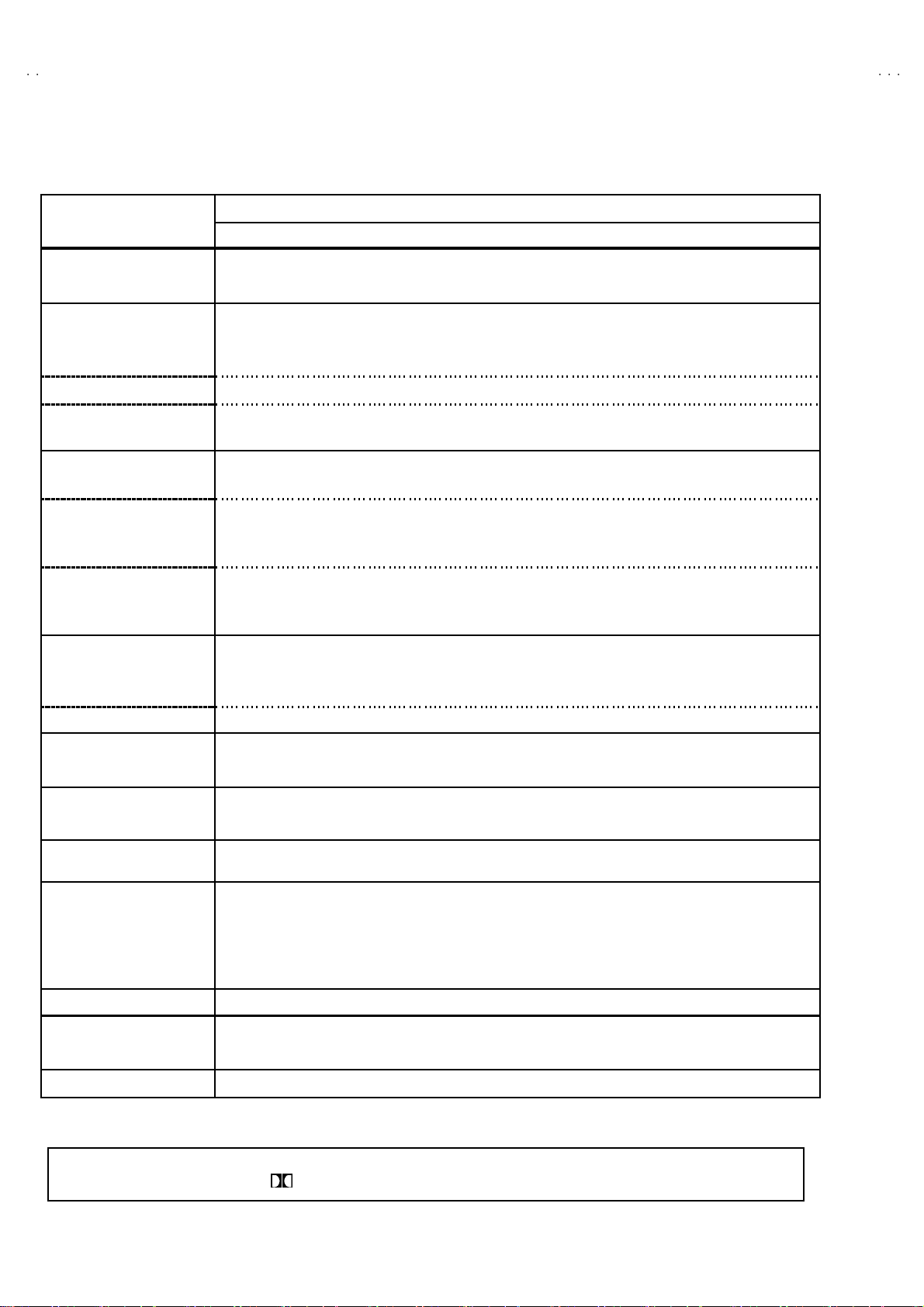
SPECIFICATIONS
Item
Dimensions ( W××××H××××D ) 85 4mm× 5 07. 5mm×493. 5mm
Mass 43 .0 kg
TV RF System CCIR ( I )
Colour Sy stem PA L
NTSC (Only in EXT mode)
Stere o Sy stem NICAM
Teletext System FLOF (Fastext)
WST(Standard system)
Receiving Frequency
UHF 47 0MHz ~ 862MHz
Intermediate Frequency
VIF Carrier 38.9MHz ( I )
SIF Car rier 32.9 MHz ( 6 .0MHz:I )
Colour Sub Carrier Freq.
PAL 4.43MHz
NT S C 3.58MHz / 4.43MHz
Power Input AC 220V ~2 40V , 5 0Hz
Power Consumption 20 0W (Max) / 1 25W ( Avg)
St andby : 3W
Aerial Input Term
Picture Tube Visi ble size : 66c m, Meas ured dia gon ally
Hi g h Volt age 31.0kV (at zero beam current)
Speaker
Au dio Output 10 W + 10W + 10W + 18W
EX T-1 /EXT-2/ EXT -3
(Input / Output)
EXT-4 (Input) Video 1V p- p 7 5Ω(RCA pi n jack)
Au di o (L /R ) 50 0mVrms( -4dB s ) , High Impedan ce ( RCA pin jack )
S / Video Y : 1V
AUDIO OUT (Variable)
SURROUND REAR output 7.5 W + 7.5 W , Imped anc e 8Ω(Pus h ter minal)
Headphone jack
Remote Control Unit RM-C 60 H-1 C ( A AA/R 0 3 dr y bat tery×2)
75 Ωun ba lanc ed, C oaxial
1kV
+
-1. 5kV
6.5 cm×13cm Ova l type×2 (si d e) , 4c m×16cm Ova l type×2 (c enter),φ13cm Round type(sub woofer)
21 -pin E uro c onnecto r
(SCART socket)
p-p
POSITIVE (Negative sync Provided, when terminated with 75Ω)
C : 0 .28 6V
0~1Vrm s, Low Impedance (RCA pin jack×2)
St ereo min i j ac k (φ3.5mm )
p-p
(Burst signal, when terminated with 75Ω)
AV28R25EKS / AV28R250EKS
Content
De sign & speci ficatio ns are subject to change wi thout notice .
★Manufact ured u nder licens e from Do lby L abo ra tor i es Licen sing Corp or at ion.
“
Dolby”an d t he do uble -D s ymb ol are trademark s of Dol b y Laboratories Lic en si ng C o rporat ion.
2
No.51941
Page 3
A
V28R25EK
S
A
S
V28R250EK
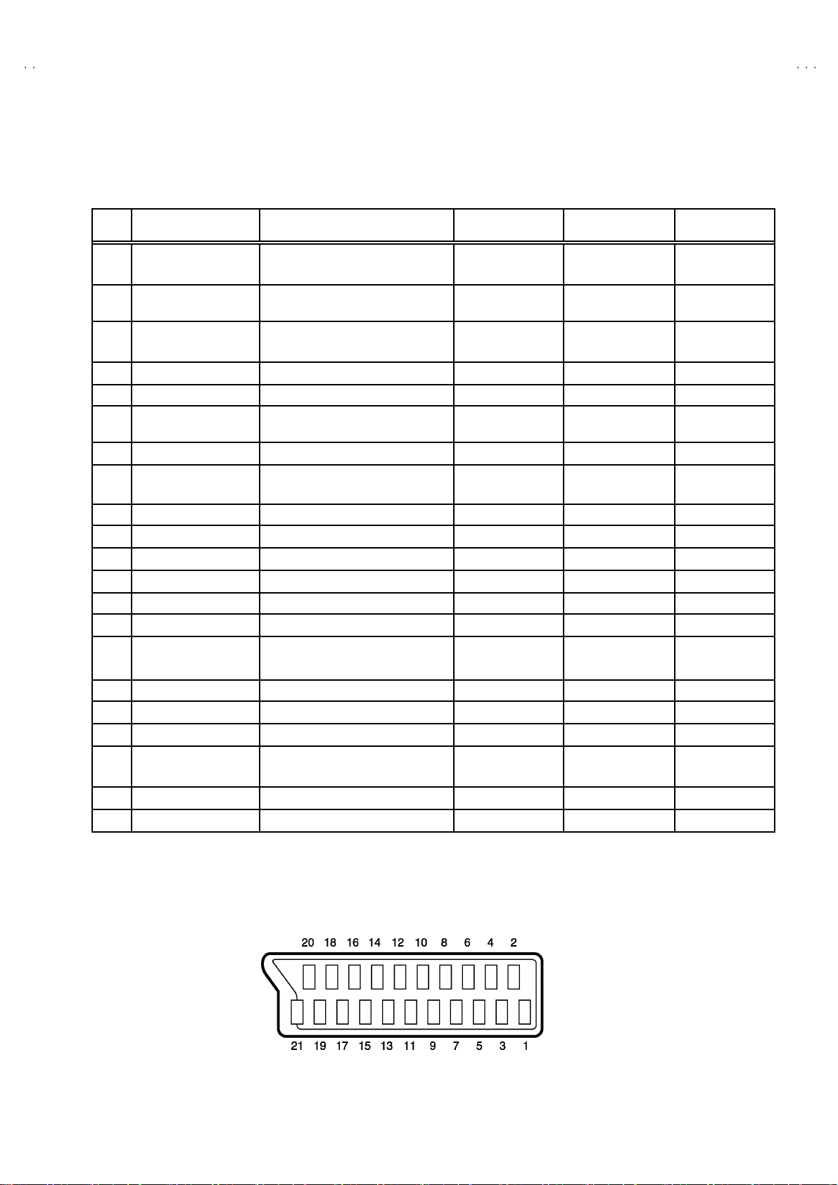
■■■■21-pin Euro connector (SCART socket) : EXT-1 / EXT-2 / EXT-3
(P-P= Peak to Peak, S-W= Sync tip to white peak, B-W= Blanking to white peak)
Pin
Signal Designation Matching Value EXT-1 EXT-2 EXT-3
No .
1 AUDIO R out put 500m Vrms( Nomina l) ,
Low impedance
2 AUDIO R in put 50 0mVrms(Nom ina l),
High i mpe da nce
3 AUDIO L o utp ut 50 0mVrms(Nom ina l),
Low impedance
4 AUDIO G ND ○○○
5 GND (B)
6 AUDIO L input 500mVrms(Nominal),
High i mpe da nce
7B input 700mV
8 FUNCTON SW
(SLOW SW)
9 GND (G)
10 SCL3 NC ○ NC
11 G in put 700m V
12 SDA3 NC ○ NC
13 GND (R)
14 GND (YS) ○ NC NC
15 R / C input R : 700mV
16 Ys i n put
17 GND(VIDEO output) ○○○
18 GND(VIDEO input) ○○○
19 VIDEO ou tpu t 1V
20 VIDEO / Y input 1V
21 COM MON G ND ○○○
Low : 0-3V, High : 8-12V, High
impedance
C : 300mV
Low : 0 - 0.4, High : 1 - 3V, 75Ω○
, 75Ω○NC NC
B- W
, 75Ω○NC NC
B- W
, 75Ω
B-W
, 75Ω
P- P
(Nega tive goin g sync ), 75 Ω○
P- P
(Nega tive goin g sync ), 75 Ω○ ○ ○
P- P
○
(TV OUT)
○○○
○
(TV OUT)
○○○
○○○
○○○
○○○
○○○
○
(only R)
(TV)
○
(LINE OUT)
○
(LINE OUT)
○
(only C)
NC NC
○
(LINE OUT)
NC
NC
○
(only C)
NC
[Pin a ssignment]
No.51941
3
Page 4

A
V28R25EKS
A
V28R250EKS
SAFETY PRECAUTIONS
1. The des ign of thi s pr o du ct c ont ains speci al hard wa re and ma ny
circuit s and components specially for safety purposes. For
con tinu ed pr ot ection, n o chan ges sh ould b e ma de to the orig i nal
d esi gn un less auth or ized i n writi n g by the manufact urer.
Replacement p arts m ust b e ident ic al to thos e u sed in th e origin al
ci rcu it s. S er vi ce sho ul d b e p erfor med by qu al if ied pers on nel
on ly.
2. Alte rations of the desi g n or ci rc uitr y of th e pr od uct sho ul d no t b e
made. Any design alterations or additions will void the
manufact urer 's warr a nt y and wi ll f urth er reli eve t he manufacturer
of r esp ons ibility for per so na l inj ury or p r op er ty damag e r esult ing
th erefr om.
3. Many el ectri cal a nd me chanic al parts i n the pr od uct h ave speci al
saf ety- r elat ed ch aract erist ics. Thes e charac ter isti cs a re oft en not
evi d ent from visu al inspecti o n no r c an th e p r otect ion af for de d by
th em n eces s ar y be obta ined by using replac em ent components
rate d for higher volta ge, wa tta ge , etc . Re placem en t p art s whic h
WARNING
h ave these speci al saf et y charac ter i stic s ar e i d ent if ied in th e
Pa rts Li st of S er vice Manual. Elec tr ical co mp on en ts h aving suc h
fe atur es are ide nti fi ed b y sh ad in g on th e sche ma tic s a nd by (!)
on t he Par ts List i n the Ser vic e Manual. The us e of a substi tut e
replac em ent which d oes not h ave the s am e saf ety
ch ar acteris ti cs as the recom mend ed replac e ment p ar t shown i n
th e P ar ts List of Service M an ual may cau s e sh oc k, f ire, or ot her
hazards.
4. The l ea ds in the products are routed an d d r essed wit h t ies,
cl am ps, tu bing’s, b ar rie rs and t he lik e t o be separated fr om live
p arts, high t empe ra tur e parts, movi ng par ts and / or sh ar p ed ge s
for t he p r evention of e l ectri c sh ock and fi r e h azar d. W he n
ser vice is re qu ired , the origi n al lead routin g and dre ss should b e
ob ser ved, and it sh oul d b e confirm ed t hat th ey h ave b ee n
retu rned to no rmal, aft er re-assemblin g.
1. The equi pm e nt h as been desi g ned a nd m anu fact ur ed to me et inte rn ati o nal saf ety sta nd ards.
2. It i s t he leg al r esp onsib il ity o f the repairer t o ensure that t hese s afet y sta nd ards ar e m aint ained.
3. Repairs mus t b e m ad e in acc ordan ce with th e rele vant saf ety st andar ds .
4. It i s essen tial t hat s af ety cr i ti cal c ompon ents ar e replac ed by a ppro ved parts.
5. If main s volt age sel ec tor i s prov ided, ch eck s etti n g f or loca l vol tag e.
4
No.51941
Page 5
A
S
A
S
FEATURES
V28R25EK
V28R250EK
"
By pref erenc e, us ers can sel e ct th e pictur e siz e fr om REG ULAR,
PANO RAMIC, F ULL, 14:9 ZOOM, 16:9 ZOO M, 16:9 ZOOM SUB
TITL E mod es. W he n th e TV u nit recei ved WSS pict ur e si gn al, th e
pictu re can b e ch anged t o 16:9 ZOOM mod e automatic ally.
" The TELE TEXT S YSTE M has a b uilt-i n FAS TEXT, and WST
system.
" Be c aus e this TV un it cor r esp on ds t o m ultiple x broa dca s t, u s ers
can enjoy music programs and sporting events with live realism.
In ad di ti on , BI LINGUAL program s can b e h ear d in th ei r orig in al
language.
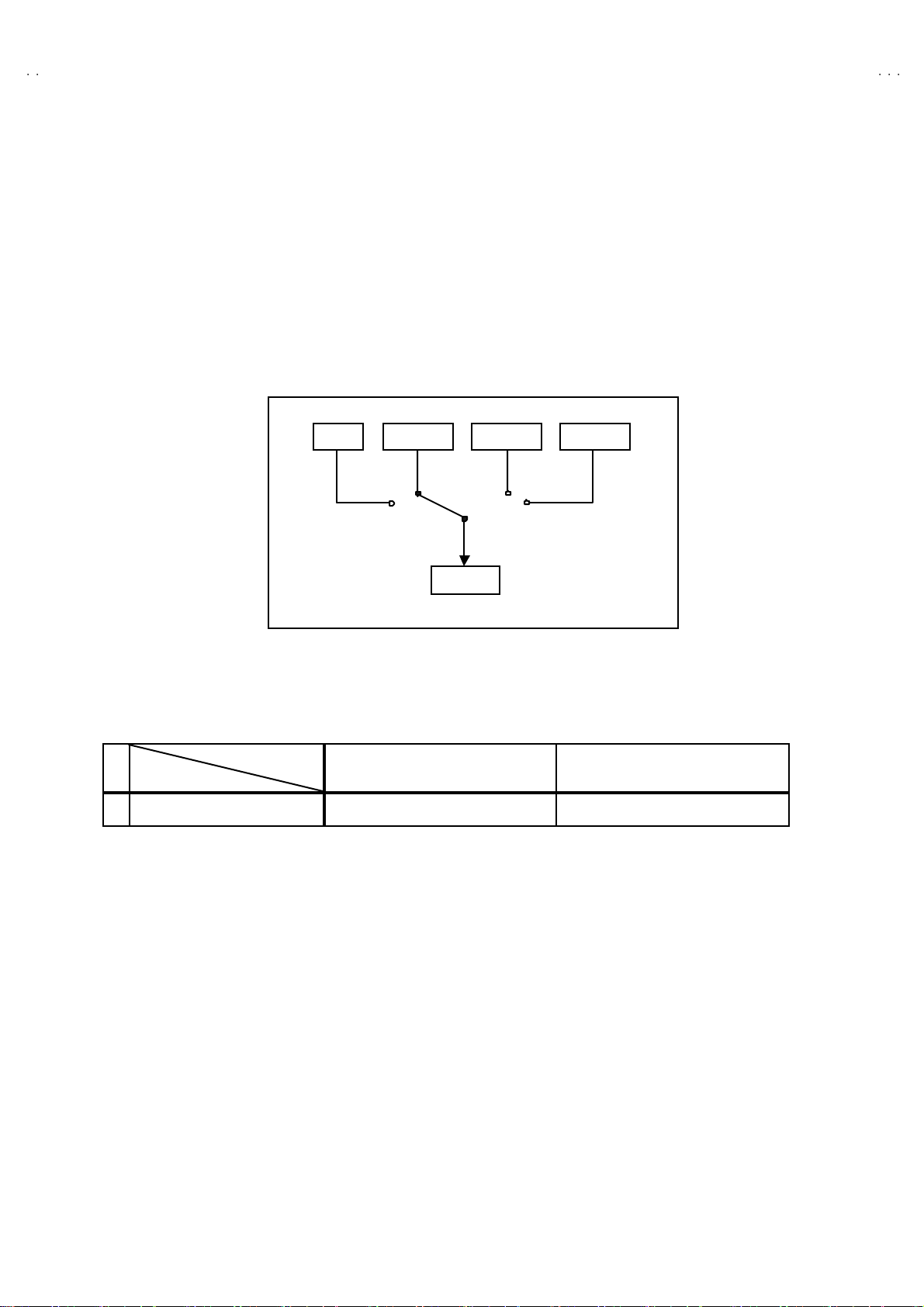
TV EXT-1 EXT-3
EXT-2
"
Users can make VCR dubbing of picture and sound by controlling
th e AV s elec tor to s e lect an optio na l so urc e at the EXT- 2 output
sh own in figure.
" Built- i nn DOLB Y PR O LOGIC 3D- PH ON E f unction.
EXT-4
MAIN DIFFERENCE LIST
Model Name
!!!!
Part Name
!
RATING LABEL LC11364-001A-U LC11364-011A-U
AV28 R2 5EKS AV28 R2 50E KS
No.51941
5
Page 6
A
V28R25EKS
A
V28R250EKS
SPECIFIC SERVICE INSTRUCTIONS
DISASSEMBLY PROCEDURE
REMOVING THE REAR COVER
1. Unplug t he po wer c ord.
2. R emove th e SUB WOOFER CORD from the A V TE RMINAL.
3. Pu ll up the S UB WOO FE R UNI T on th e top of th e r ear c over
up ward.
4. Remove the 13 screws marked A as s hown in t he F ig. 1.
5. Withdraw the rear cover to wa rd you .
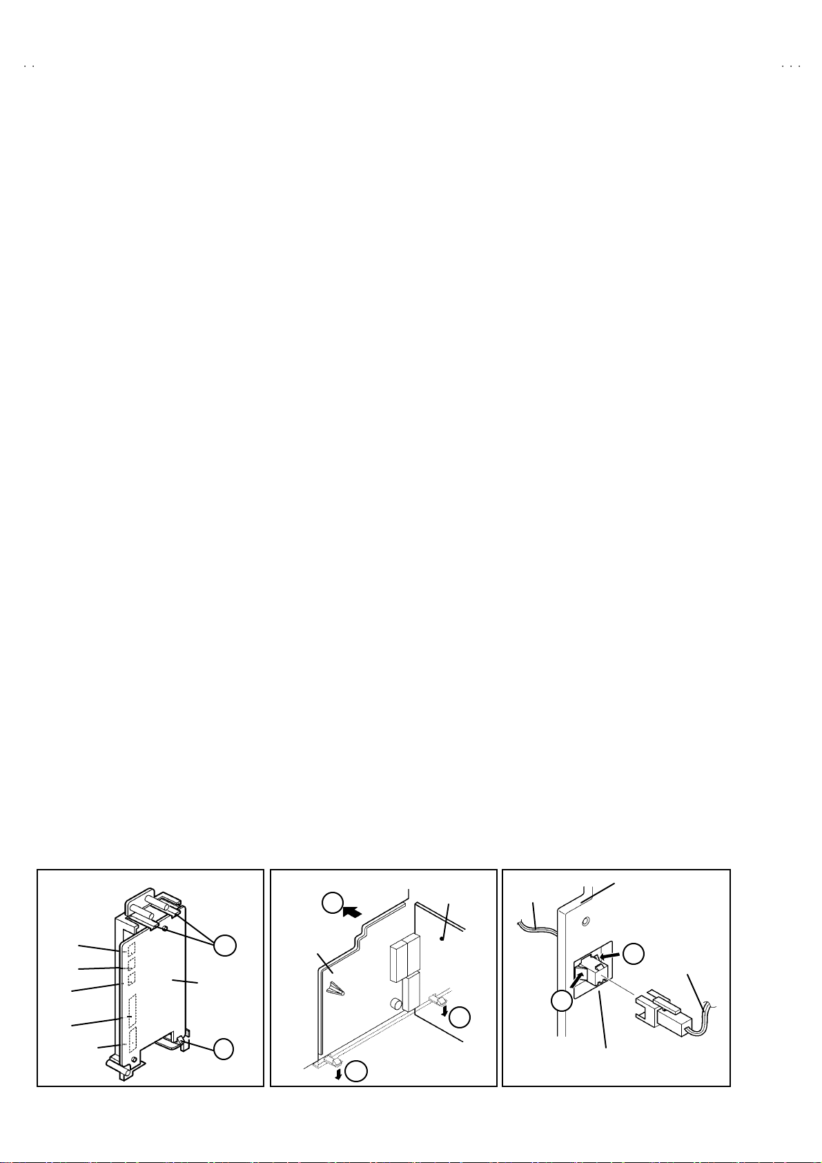
REMOVING THE SIDE CONTROL JACK ASSEMBLY
"
After removing the rear cover.
1. Remov e th e scr ew mar ked B as sh own in the Fi g.1 .
2. Whil e sli ght l y rai se the si d e c ontrol jack ass e mbly, r emove th e 2
claws under the side control jack assembly.
3. Disc onn ec t th e c onn ector “SR ”, “ SL ”, “ S”, “F” and “CN016” as
shown in Fig 2.
REMOVING THE SIDE CONT ROL PWB
" Af ter r emovi ng th e r e ar cov er and si d e co ntrol j ac k ass embl y.
1. Remov e th e 3 claw s C from back side of the side control jack
asse mbly as s hown in Fig. 2.
2. Pull out the SIDE C ONTROL PW B.
REMOVING THE CHASS IS
"
After removing the rear cover.
1. Slight ly r aise th e bo th si de s of th e c has si s by h and and r e mo ve
th e t w o claws u nd er the both si d es of the chassis from t he fr o nt
cab inet .
2. Withdraw the chass is backwa rd.
(If necessary, take off the wire clamp, connectors etc.)
REMOVING THE CENTER SPEAKER
" After removing the rear cover and chas sis.
1. Remov e t he 2 scr ews m ar ked D as sh own i n Fi g. 1.
2. Remov e th e cente r spea ker. I f n ecess ary , d eta ch th e c ables .
REMOVING THE SIDE SPEAKER
" After removing the rear cover.
1. Remov e t he 2 scr ews m arked E, and remove the s p eake r hol d er
as s hown i n Fig. 1.
NOTE : When r emoving the screws marked E of t he speaker
remov e t he lo wer s ide screw fi r st, an d t hen r em ove the
up per one.
2. Remove the 2 screws F attaching the sp eaker.
3. Fol l ow th e s ame st eps wh en r emovi ng th e oth er ha nd speake r.
REMOVING THE AV TERMINAL BOARD
"
After removing the rear cover.
1. Remov e th e 5 scr ews m arked G as show n in t he Fig. 1 .
2. Remove the 2 claws marked H under the CHASSIS as shown in
Fig. 3.
3. Remove the AV TERMINAL BOARD slightly in the direction of
arrow I as show n i n Fi g. 3.
4. After removing the craw J on t he co nn ec tor for SU B W OO FE R,
pu ll out the co nnecto r f or SUB W OOF ER. (Fi g. 4)
CHECKING THE PW BOARD
To c h eck the b ack side of th e PW B oar d.
1) Pull out the chassis. (Refer to RE MOVING TH E CHASSIS ).
2) Erect the chassis vertically so that you can easily check the
b ack si de of the PW Board.
[CAUTION]
"
When erecting the chassis, be careful so that there will be no
contacting with other PW Board.
"
Be for e tur n in g on po wer, make sure that the wire co nn ector is
properly con nec ted .
"
When co ndu cting a ch eck with p ower su pplied , b e sure to c onfi r m
th at t he CRT E AR TH W I RE (B RA ID ED AS S’ Y) is co nne cted t o
th e C RT SOC KE T PW b oar d.
WIRE CLAMPING AND CABLE T YING
1. Be sure to cl amp th e wire.
2. Never remove th e cable tie use d f or tying the wi re s togethe r.
Sh ould it be in adv e rt ent l y rem oved, b e su r e to tie the wir es w it h
a n ew c able tie.
WO OFER
I
Connector
SR
SL
S
F
CN016
C
SI DE
C ONT RO L
PWB
C
(Back view)
Fig. 2
6
AV TERMINAL
BOARD
H
Fig. 3
No.51941
AV SW PWB
H
CORD
J
CONNE CT OR for
SUB WOOFER
AV TERMINAL
BOARD
J
Fig. 4
SUB WOOFER
CORD
Page 7

A
S
A
S
FRONT CABINET
S
(
)
(
)
CRT
SOCKET
PWB
AV SW
PWB
V28R25EK
V28R250EK
E
F
SI DE
PEAKER
POWER & DEF.
PWB
CLAW
CHASSIS
Fig.2
SI DE CONT R O L
JACK ASSEMBLY
REAR COVER
FRONT
C ONT RO L
PWB
CENTER
SP EAKE R
C ONT RO L
BASE
CLAW
DOLBY
PWB
MAIN
PWB
Fig.4
B
D
×
2
SUB WOOFER UNIT
SUB WOOFER CORD
AV TERMINAL
BOARD
G
(×5)
POWER CORD
A
×13
Fig. 1
No.51941
7
Page 8

A
V28R25EKS
A
V28R250EKS
REMOVING THE CRT
∗
Replacement of th e CR T s ho uld be performed by 2 or more
p ers ons.
• After removing the c over, ch assis etc.,
1. Pu tti ng th e CRT c han ge ta ble o n sof t cl oth , the CR T cha ng e tabl e
sh ould also b e cover e d with s uch soft clot h ( sho wn in Fi g. 5).
2. Whil e keepin g the s urf ac e of CRT down, mount the TV s et on t he
CRT change table balanced will as shown in Fig.6.
3. R em ove 4 sc re ws mar ke d by arro ws with a box ty p e sc rew dri ver
as s hown in Fig. 6.
• Sinc e the cab inet will drop wh en scr ews h ave been remo ve d, be
sure t o su pport t he cabinet with h ands.
4. After 4 screws have been removed, put the cabinet slowly on
cloth (At thi s time, be care fully so as not to damag e the fr ont
sur fac e of th e cabin et) s h own in Fig.7 .
• T he C RT should b e as s em bl ed acc ordin g to th e o pp os ite
sequence of its dismounting steps.
∗
The C RT change t ab le sh ould pref er ab ly b e smal l er t hat the CRT
sur fac e, and i ts heigh t be about 35c m.
CRT CHANGE TABLE
AP PROX.
35 cm
CLOTH
Fig. 5
CRT
CRT
CHANGE
TABLE
BOX
TYPE
SCREW
DRI VER
Fig. 6
CRT
CABINET
Fig. 7
CRT
CHANGE TA BLE
CAUTION
•
The woof er un it is m ou nt ed on th e TV . Al w ays move th e TV a nd wo ofe r unit t ogeth er w hen removin g th e TV f ro m th e b ox, o r when
movi ng th e w oo fer u ni t.
• If the TV is tilted during movement the woofer unit may fall. Be careful to keep the TV level when moving it.
• Do not grip the woofe r unit whe n moving the TV.
• Do not plac e ob jects on the woof er u nit d uct.
8
No. 51941
Page 9
A
S
A
S
REPLACEMENT OF MEMORY ICs
1. Memory ICs
This TV use memory ICs. In the memory ICs, there are memorized data
for cor r ectly op erating th e video an d def lecti on cir cu its . Wh en r ep l aci ng
memor y ICs, b e sure t o us e ICs wri tte n wi th th e initial values of data.
2. Procedure for replacing memory ICs
PROCEDURE
(1) Powe r off
Switch the pow er of f an d un plug th e pow er cor d f rom t he ou tlet.
V28R25EK
V28R250EK
(2) R epla ce ICs.
Be sure to use memory ICs written with the initial data values.
(3) Power on
Plug th e p ower c or d int o th e outl et a nd s witc h t he po we r on.
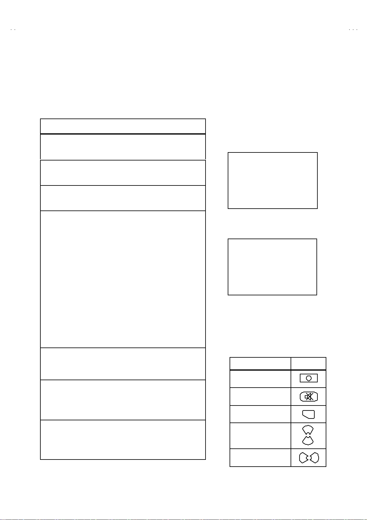
(4) C heck and set SY STEM CO NSTANT SET :
It must n ot adjust wit hout sig nal.
****
1) Pr ess th e IN FO RMATI ON ke y and the MUTING key of th e
REMO TE CONTROL UNIT simultaneously.
2) The SERVICE MENU screen of Fig. 1 will be displayed.
3) Whil e th e S ERVICE ME NU is di spla y ed, p r ess t he
INFORMATION key and MUTING key s imultaneously, and the
SYSTEM CONSTANT SET screen of Fig. 2 will be displayed.
4) C heck th e s e tti ng values of the S YSTEM CONST A NT SET of
Table 1. If the value is d ifferent, se lect the s ettin g item with th e
FUNCTION U P/DOWN key, and s et t he c orr ect va lue with the
FUNCTION - /+ key.
5) Press the MENU key to memorize the setting value.
6) Pres s t he IN FORM AT ION key t wice, a nd retu rn t o th e no rm al
screen.
SE RVIC E ME NU
1. IF 2. V/C
3. AUDIO 4. DEF
5. VS M PRES ET 6 . VPS
7. SHIPPING (OFF)
1- 7 : SEL ECT i : EXIT
Fig.1
SY STEM C ONS TAN T S ET
MODEL=JL_EURO(
1. DESTINATION : EK
JVC JL EURO V0 0
*** ****
- + OK: STORE i : EXIT
*.*** *
Fig.2
)
(5) Se tt in g o f re ceive channe ls
Se t th e rec eiv e ch anne l.
NAME OF REMOTE CONTROL KEY
Names of key
key
For setting, ref er to the OPERATING INS TRUC TIONS.
INFORMATION
iiii
(6) U ser se tt in gs
Check the us er sett ing val ues of Tab le 2, and i f sett in g val ue i s
MUTI NG
diff er ent , s et th e c orrec t valu e.
For setting, ref er to the OPERATING INS TRUC TIONS.
OK
▼
▼
(7) Setting of SERVICE MENU
Ve rif y the set ting it ems of th e SER VICE ME NU of Tab le 3, and r eset
where necessary.
MENU
FUNCTION UP/DOWN
For setting, ref er to the SERV ICE ADJUSTMENT S.
▼
FUNCTION -/ +
No. 51941
▼
9
Page 10

A
V28R25EKS
A
V28R250EKS
SETT I NG VALU ES OF SY ST EM CONS TANT SE T (TABLE 1)
Setting item Setting content Setting value Setting item Setting content Setting value
1.DEST INATION EK 5.CO MB YE S NO NO
2.DOLBY YES NO YES 6.PICTUR TILT YES NO NO
3.BBE YES NO NO 7.FLAT YES NO YES
4.TV SPE AK ER YE S NO YES 8.3 -D YE S NO NO
EK EPEI
USER SETTING VALUES (TABLE 2)
SOUND LEVEL 10 SUB POWER ON
SHIPPING CHANNEL 1 ZOOM MODE PANORAMIC
USER MENU SE TT ING
PICTURE SE TTING EX T SET TI NG
TINT
CONTRAST
BRIGHT
SHAR P
COLOUR
PICTURE FEATURES FEATURES
AUT O VNR
COLOUR SYSTE M
4:3 AUT O ASPE CT
STEREO /
BA SS
TR EBL E
PRO L OGIC 3-D PHONIC
LEVEL
Ⅰ・Ⅱ
DIGITAL SURROUND
COOL
REFER to VSM PRESET
AUT O
TV : Acc o rding t o preset CH
EXT : AUTO
PA NO RA MI C
SOUND SETTING INSTALL
CENTER
CENTER
CINEMA / SPORT
CENTER
DUBBING
SLEEP TIME R
BLUE BA CK
CHILD LOCK
DECODER (EXT-2)
LA NG UA G E
EDIT/MANU AL
DEMO OFF
EXT- 1→EX T-2
OFF
ON
ID : No.****
ALL CH OFF
OFF
ENGL ISH
PRES ET CH on ly
The others : BLANK
SERVICE MENU SETTING ITEMS (TABLE 3)
Setting item Setting value Setting item Setting value
1. IF VCO 4. DEF. 1. V-SHIFT
2. V / C 1. CUT OFF
3. AUDIO
(Do not a djust)
2. DRIVE
3. BRIGHT
4. CONT.
5. COLO UR
6. HUE
7. BLACK O FFS ET (Only SEC AM)
8. SHAR P
1. ERROR LIMIT
2. A2 ID T HR
3. BA SS
4. TR EBL E
5. VS M PRESE T
COOL
NORMAL
WARM
6. VP S
(Do not a djust)
7. SH IPP ING
(Do not a djust)
2. V-SIZE
3. SUBT IT LE
4. H-CENT
5. H-SIZE
6. EW - PIN
7. TR APE Z
8. EW. COR. L
9. EW. COR. H
10. V. S-COR
11 . V- LIN
12. H- BL K-R
13. H- BL K-L
14. V-EH T
15 . H -EHT
16. EHT-GAIN
1. BRIGHT
2. CONT.
3. COLO UR
4. SHAR P
5. HUE
6. R DRIVE
7. B DR IVE
VP S
PDC
WSS
ON / O FF
10
No. 51941
Page 11

A
S
A
S
REPLACEMENT OF CHIP COMPONENT
! CAUTIONS
1. Avoid heating for more than 3 seconds.
2. Do not rub t he elect rodes an d t he r esi st p arts of th e p att ern.
3. W hen remov ing a c hip part, melt th e solder adequ atel y.
4. Do not reuse a chip p art afte r remov ing it.
! SOLDERING IRON
1. Use a hig h ins ulation s oldering ir on with a t hin pointed end of it .
2. A 3 0 w s oldering ir on is r ec omm end ed for easil y rem oving par ts .
!
REPLACEMENT ST EPS
1. How to remove Chip parts
####
Resi stors, capacito rs , etc
(1) As sh own in the figur e, pu sh th e pa rt with twee zer s and
alte rnat ely m elt th e solde r at eac h en d.
(2) Shift with tweez e rs an d remo ve the ch i p p art.
#### Trans isto rs, dio des, va riable r esist ors, et c
(1) Apply e xtra s o lder to each l e ad .
SOLDE R SOLD ER
V28R25EK
V28R250EK
2. How to install Chip parts
####
Resi stors, ca pacitors, etc
(1) Apply sold er to th e patt ern as i ndic ated in the figure.
(2) Gr asp the ch i p p art with tweezer s and pl ac e it on th e s older.
The n hea t and melt the so ld er a t b oth ends of t he chip part.
#### Trans isto rs, diodes , varia bl e r esistor s, etc
(1) Apply sold er to th e patt ern as i ndic ated in the figure.
(2) Grasp th e chip p art w it h t we ezers an d p lace it on th e so lder.
(3) First solder lead A as indica ted in t he figure.
A
(2) As sh own in the figur e, pu sh th e pa rt with twee zer s and
alte rnat ely m elt th e sold er at eac h lead. S hi ft an d r em ove t he
chip part.
(4) T he n solder l e ads B and C.
Note : After remo ving t he part , remove remainin g solder fr om the
pattern.
C
A
C
No.51941
B
B
11
Page 12

A
V28R25EKS
A
V28R250EKS
SERVICE ADJUSTMENTS
BEFORE STARTING SERVICE ADJUSTMENT
1. There ar e 2 w ays o f adjust in g this T V: One is wi th t he
REMOTE CONTROL UNIT and the other is the conventional
method using adjustment parts and components.
2. The setting (adjustment) using the REMOTE CONTROL
UNIT is made on the basis of th e initial se tting values. The
se tting va lues whic h adj u st the sc reen to th e opt imum
condition can be di fferent from the initial setting values.
3. Make s ure th at connect ion i s c orrect ly made t o AC p ower
source.
4. Tur n on th e pow e r of th e TV a nd measu r ing ins tr umen t for
warmi n g u p f or at least 30 min ut es b ef or e start ing adju stment .
5. If th e r ec ei ve or inp ut signal i s not sp eci fi ed , use t he m ost
ap propria te s ignal for a djust ment.
6. N ever tou c h p arts ( such as var iab le r es ist or s, tr an sform er s and
condensers) not shown in the adjustment items of this service
adjustment.
7. Pr ep aration f or ad justm en t ( pr es etting):
Unless oth er w is e speci fi ed in th e a djust me nt items , p r ese t th e
follo win g functio ns with the REMOTE CO NTROL UNIT:
" Setting posit ion
PICTURE MODE (VSM) NORMAL
SLEEP TIMER OFF
BALANCE CENTER
ZOOM PANORAMIC
MEASURING INSTRUMENT AND FIXTURES
1. DC voltmeter (or digital voltmeter)
2. Oscilloscope
3. Signal g ener ator (P att ern g ener at or) [ PAL / NT SC ]
4. Remote control unit
ADJUSTMENT ITEMS
●
B1 POWER SU PPL Y ch eck.
●
HIGH VOLTAGE check.
●
FOCUS Adjustment.
●
IF ci rcui t adjust ment.
●
VS M p reset adju st s ettin g.
●
VIDEO / CHROMA circ uit adjustment.
●
DEFLECTION c ircuit adjustment.
●
H BLA NKING adjus tm ent.
●
AUDIO circuit adjustment. (Do not adjust)
12
No. 51941
Page 13

A
S
A
S
ADJUSTMENT LOCATIONS
CN009
CN008
(
)
)
C
SC
C30
S
CN016
V28R25EK
V28R250EK
SIDE CONTROL PWB
FRON T CONT ROL PWBFRONT
PO W E R SW
FRONT
CN00S
CN0SW
DOLB Y PWB
TOP
HE AD
PH O NE
F8901
PW
CN001
W
UP
DOW N
MENU
MAIN PWB POWER&DEF PWB
CN001
CN0SC
IC701
CN016
IC702
MEMORY
W
E
X
T
4
S-IN
FRONT
DEG
R
SL
S
F
AV SW PW B
CN012 C N006
TUNER
F
CRT SO C KET P WB
TP-47R
TP-47G
I
1
CN008
SOLDER SIDE
TP-47B
E1
TOP
CN009
HV
X
1
5
1pin :B 1(TP -91
2pin :N
3pin:NC
4pin:NC
5p in: G ND(T P-E)
FOC US
R EEN
TP-E
No. 51941
13
Page 14

A
V28R25EKS
A
y
y
V28R250EKS
BASIC OPERATION SERVICE MENU
1. TOOL OF SERVICE MEN U OPE RATION
Operate the SERVICE MENU with the REMOTE CONTROL UNIT.
2. SE RVICE MENU ITEMS
With the SER VI CE MENU, var ious sett in gs ( ad ju stments) c an b e made , a nd th ey a re broadly c la ssif ied in the f ollow ing items of set tings
(adjus tm ents ):
(1) 1. IF ・・・・・・・ ・・・・・・・・・・・・・ ・・・ This mod e adjust s th e setting valu es o f the IF circu it.
(2) 2.V /C ・・・・・・・・・・・・・・・・・・・・・・ This m ode adjust s the se tting valu es o f th e VIDEO / CH ROMA circu it.
(3) 3.AUDIO・・・・・・・ ・・・・・・・・・・・・ This mode adjusts the setting values of the multiplic it y SOUND circuit. (Do not adjust)
(4) 4. DEF ・・・・・・・ ・・・・・・・・・・・・・・ Thi s m od e adjust s th e setti ng val u es of th e DE FLECT ION cir cuit f or eac h aspect mod e g iven belo w.
REGULAR (50/ 60 Hz)
PA NO RA MI C ( 50/ 6 0Hz)
14 :9 ZO OM (50/ 60Hz)
16 :9 ZO OM (50/ 60Hz)
16 :9 S UB TITL E (50/ 60Hz)
FU LL ( 50/60Hz)
(5) 5.V SM PRESE T・・・・・・・・・・・・・ This m od e adj ust s th e in itia l sett in g val ues of CO OL, NORMAL an d W ARM.
(VS M : V i de o Sta tus Memory )
(6) 6.V PS ・・・・・・・・・・・・・・・・・・・・ ・ T his m od e sh ows the monitor of t he VP S, PDC a nd W SS . (Do not adjust)
(VP S : Vide o Pro gram Syst em, PDC : Program Deliver y Code, WSS : Wide Scr een Signalling)
(7) 7.SHIPPING ・・・・・・・・・・・・・・・・ This men u is s et at sh ipping. (Do not adjust)
3. BASIC OPERATION OF SERVICE MENU
(1) How to enter SERVICE MENU
Press the INFORMATION key and the MUTING key of the
REMOTE C ON TROL UNI T si mu ltan eou sl y, an d th e
SERVICE MENU screen of Fig. 1 will be displayed.
(2) Selection of SUB MENU SCREEN
Press one of keys 1~7 of the REMOTE CONTROL UNIT
an d sel e ct th e S UB M ENU SCR EEN (See Fi g. 3 ), fo rm th e
SERVICE MENU.
SERVICE MENU → SUB ME NU
1. IF
2. V / C
3. AUDIO
4. DE F.
5. VSM PRESET
6. VP S
7. SHIPPING
SE RVICE M ENU
SE R VIC E ME NU
1. IF 2. V/C
3. AUDIO 4. DEF
5. VSM PRESET 6. VPS
7. SHIPPING (OFF)
1-7 : SELECT i
NEME OF REM OTE CONTOR OL KEY
Names of ke
INFORMATION
MUTI NG
MENU
FUNCTION UP/DOWN
FUNCTION -/ +
Fig.1
Fig.2
: EXI T
ke
i
i
OK
▼
▼
▼
▼
14
No. 51941
Page 15

A
S
A
S
SERVICE MENU
SERVIC E MENU
1. IF 2. V/C
3. AUDIO 4. DEF
5. VSM PRESET 6. VPS
7. SHPIING (OFF)
1-7 : SELECT i : EXIT
7. SHIPPING
7. SHI PPING(O FF)
7. SHI PPING (ON)
V28R25EK
V28R250EK
Do not ad just
COOL
NOR MAL
WARM
1. BR IGHT
2. CONT .
3. COL OU R
4. SHA RP
5. HU E
6. R DR IV E
7. B DR IV E
Do not ad just
5. VSM PRESET
VSM PRESET NORM AL
1. BR IGHT
- + OK : STORE i : EXIT
VPS = 0000H(- - -)
PD C 8 / 30 / 1 = 0 000 H
WSS = 0 000
***
6. VPS
VPS
= 0 000 H
i : EXIT
1.IF (VCO)
VCO (CW)
TOO HIGH
ABOVE REFER ENCE
JUST REFE RENCE
BEL OW R EFE RE NC E
TOO LOW
V/C
1. CUT OFF (R)
- + OK : STORE i : EXIT
**
** ....**
****
2. V/ C
PAL
**
****
(G)
(B)
MHz
****
****
****
i: EXIT
1. CUT OFF
2. DR IVE
3. BR IGHT
4. CONT .
5. COL OU R
6. HU E
7. BLAC K OFFS ET
8. SHARP (Do not adj ust)
3. AU DIO
AU DIO
1. ERROR LIM IT = 10 0H
ERROR RATE = 7F0H
C_ AD _BI TS = 00 000000
- + OK : STORE i : EXIT
4. DEF
DEF PANORAMIC
1. V- SHIFT
- + OK : STORE i : EXIT
Fig. 3 SUB MENU SCREEN
***
(**)
Do not ad just
1. ERROR LIMIT
2. A2 ID THR
3. BA SS
4. TREBLE
1. V-SHIFT
2. V-SIZE
3. SUBTITLE
4. H-C ENT
5. H-SI Z E
Hz
**
**
****
6. EW -PIN
7. TRAPEZ
8. EW.COR.L
9. EW.COR.H
10. V.S-COR
11 . V-L I N
12 . H -BL K-R
13 . H -BL K-L
14. V-EHT(Do not adjust)
15 . H -EHT (Do not adju s t)
16 . EH T-G A IN (D o n o t ad ju st)
No. 51941
15
Page 16

A
V28R25EKS
A
V28R250EKS
(3) Method of Setting
1) M eth od of Set ting 1. IF
[VCO]
① 1 Key・・・・・・・ ・・・・・・・・・・・・・ ・・・・・ Select 1 .IF.
② The VCO (CW) screen will be displayed in yellow when the AFC voltage is at a certain level and in blue when it is at other levels .
③ INFOR MATION K ey ・・・・・・・ ・・・・・ Retu rn t o th e SER VICE MENU screen.
2) Method of s ett ing 2.V/C, 3.AUDIO, 4.DEF and 5.VSM PRESET.
① 2~5 K ey・・・・・・・・・・・・・・・・・・・・・・ Select one from 2.V/C, 3.AUDIO, 4.DEF and 5.VSM PRESET.
② FUNCTION UP / D OWN Key ・・・・ Select s etting items.
③ FUNCTION -/+・・・・・・・ ・・・・・・・・・・ Set (ad just) the setting valu es of the setting items.
(U se the number keys of th e REMOTE CONTROL U NIT for s etting of WHITE B ALANCE.
For the s etti n g, r ef er to eac h it em con cerne d.)
④ ME NU Key ・・・・・・・ ・・・・・・・・・・・・・ Memorize the s etting va lue.
(Bef or e st orin g t he sett in g val u es in me mo r y, do not press t he CH, TV, POW E R O N / OFF k ey -
if you d o, the values will not be store d in memory.)
⑤ INFOR MATION K ey ・・・・・・・ ・・・・・ Retu rn t o th e SERVIC E MENU screen.
3) Method of s ett ing 6.VPS and 7.SH IP PIN G.
6.V PS・・・・・・・・・・・・・・・・・・・・・・・・・・・ This mode displayed monitor of VPS systems. (Do not adjust)
7.S HIPPING ・・・・・・・ ・・・・・・・・・・・・・ ・ When the M AIN POW E R is tu rned on w ith th e state of SHIPPING O N, you g et a mode that
initializes every existing set value including language selection. Because this mode is set at the
fac tory up on compl eti on of the adjus tm e nt, you ne ed no t to us e i t f or serv ice.
(Do not a dju st in this mo de.)
(4) Rele as e of SERV ICE M ENU
1) Af ter co mp l eti ng th e setti ng , r et urn t o the SERVICE MENU, th en ag ain p r ess th e I NFORM ATIO N key.
16
No. 51941
Page 17

A
S
A
S
ADJUSTMENTS
CHECK ITEM
Item
POWER
SUPP LY
Check
Measuring
instrume nt
Signal
generator
DC vo ltmeter
Remote
control unit
Test point Ad justment part Description
TP-91(B1)
TP-E("""" )
[X connector
on POWER
DE F PW B ]
1. R ecei ve a any broa dca s t.
2. Pu sh t he “ZOOM” key an d selec t the FULL mode.
3. Sele ct 2.V/C f rom the SERVIC E MENU .
4. Select 1. C UT OFF w ith Fu nction UP/DOW N key.
5. Sh ow o ne ho rizon tal lin e wi th the 1 key.
6. Tur n the SCR EEN V R, th e wh ole blac k s cr ee n d ispl ay.
7. Connect a DC vol tm et er t o TP-91(B1) and TP- E(").
8. Make sure t hat th e volt age is DC 14 3.0V±2. 0V.
9. R ea djust the SCRE EN VR to ap pe ar t he ho ri zo ntal line fa intly,
an d ca ncel t he horizon ta l li n e t o pre ss th e 2 k ey.
V28R25EK
V28R250EK
VOLTAGE
Check
Signal
generator
DC volunteer
Remote
control unit
ADJUS TMENT OF FOCUS
Item
FOCUS
Ad j ust men t
Measuring
instrume nt
Signal
generator
CRT anode
Chassis GND
Test point Ad justment part Description
FOCUS VR
[In FBT]
1. R ecei ve a any broa dca s t.
2. Pu sh t he “ZOOM” key an d selec t the FULL mode.
3. Sele ct 2.V/C f rom the SERVIC E MENU .
4. Select 1.C UT OFF w ith Fu nction UP/DOWN key.
5. Sh ow one h oriz o nt al lin e wit h t he 1 key.
6. Tur n the SCR EEN V R, th e wh ole blac k s cr ee n d ispl ay.
7. Connect a DC voltmeter to CRT ANODE and chassis GND.
8. Make sure t hat th e volt age is DC 3 1.0kV .
9. R ea djust the SCR EEN VR t o ap pea r th e hor i zon tal line faintly,
an d c onnec t the hori zo ntal l ine to pr ess 2 key.
1. Receive a cross-hatch signal. Select FULL mode.
2. W hile watc hi ng th e scr een , adj ust th e FOCUS VR to mak e th e
ver ti cal and ho rizo ntal l ines as f ine and sha rp as possi b l e.
3. M ake s ure th at w hen the sc re en is dar kened, the l ines r e main
in good focus.
+1kV
-1.5kV
FOCUS VR
SCREEN VR
No. 51941
17
Page 18

A
V28R25EKS
A
V28R250EKS
IF CIRCUIT ADJ USTMENT
Item
Ad justment of
VCO
Measuring
instrume nt
Remote
control unit
VCO(CW)
***.**
T OO HI GH
ABOVE REFERE NCE
JUS T REFEREN CE
BEL OW REFERENCE
T OO LO W
i : EXIT
Test point Adjustment part Description
MHz
VSM PR ES ET AD JUS T S ET TIN G
Item
Setting of
VS M PRE SET
Measuring
instrume nt
Remote
control unit
Test point Ad justment part Description
fv
YELLOW
1. BRIG HT
2. CONT.
3. COLOUR
4. SHARP
5. HUE
6. R DRIVE
7. B DRIVE
"
Und er n ormal c ond itions, no ad just ment is requir ed.
1. Receive any bro adc ast.
2. Se lect 1.IF from the SERV ICE MENU.
3. Check the ch aract ers co lour of th e JUST R EFERENCE
displayed to yellow.
1. Sele ct 5.VSM PR ESET from th e SERVIC E ME NU.
2. Se lect C OOL wi th t he MENU key of t he re mo te control un it.
3. Ad ju st th e FUNCTION UP /D OW N and -/ + key t o br ing t he s et
val u es of 1.B RIG HT ~ 7.B D RIVE to the val ues sh ow n in the
tabl e.
4. Pr ess the ME NU key a nd m em oriz e th e set va lue.
5. Resp ectiv ely s elect th e VSM P RE SET m ode f or NORMAL and
WARM, and make similar adj ust ment as i n 3 abo ve.
6. Pr ess the ME NU key a nd m em oriz e th e set va lue.
∗
Refer to OPERATING IN STRUCTI ONS for the PICTUR E
MO DE .
18
VSM preset mode
Set ting item
1. BRIGHT
SE TT ING VALUE
2. CONT.
SE TT ING VALUE
3. COLO UR
SE TT ING VALUE
4. SH ARP
SE TT ING VALUE
5. HUE
SE TT ING VALUE
6. R DRIVE
SE TT ING VALUE
7. B D RIVE
SE TT ING VALUE
No. 51941
COOL NORM AL WARM
+0 +0 +0
+12 +10 +2
+6 +0 -2
+0 +0 -2
+0 +0 +0
-20 +0 +16
+23+0-13
SE TT ING VALUES OF VSM PRE SET
Page 19

A
S
A
S
VIDEO / CHR OMA CIRCUIT ADJUS TMENT
ote Control Unit
The setting (adjustment) using the REMOTE CONTROL UNIT is made on the basis of the initial setting values.
The setting values which adjust the screen to the optimum condition can be different from the initial setting values.
V28R25EK
V28R250EK
Setting Item
(Adjustment Item )
R -100 5. C OL OUR +5 +5
G -100
B - 100
R+0
2. DRIVE
B+0
3. BRIG HT +0
4. CONT. -10
Item
Ad j ust men t
of WHITE
BALANCE
(Low Light)
Measuring
instrume nt
Signal
generator
Remote
control unit
Rem
H. LIN E ON
Initial setting value
Test point Ad justment part Description
H. LIN E OF F
1.CUT OFF
(R)***
(G)
(B)***
SCREEN VR
[In FBT]
Colour sy stem
Setting item
6. HUE
7. BLACK OFFSET
(SECAM)
(Do not a djust)
8. SH ARP
(Do not a djust)
"
Set th e PICTURE MODE to NORMAL.
1. Receive a bl ack a nd white si gn al (c olour of f).
2. Sele ct 2.V/C f rom the SERVIC E MENU .
***
3. Select 1.CUT OFF wit h the FUNCTION UP/DOWN key.
4. Pu sh t he “ZOOM” key an d s elect the “REGU L AR” m ode.
5. Sh ow o ne ho rizon tal lin e wi th the 1 key.
6. Gr ad ua lly tu rn the SCR EEN V R f r om t he lef t e nd t o th e r ight
7. Press 4~9 key , a nd br ing out th e o ther 2 c olours a nd ma ke
8. T ur n th e SC REEN VR and br i ng on e white horizont al li n e
9. Pr ess 2 ke y, tu rn of f 1.CUT OFF scr een .
10 . Pr ess the ME NU key and mem oriz e the s et value.
Initial setting value
PAL
R-Y
B- Y
-20
direc tio n to br ing one of th e r ed , g reen or blue co l our f ai nt ly
vis ible.
on e h oriz ont al line vis ible i n white.
fain tly visible.
NT SC 3.5 8
NT SC 4.4 3
+21. CUTOFF
1 2 3
R CU TOF F
4 5
R CU TOF F
7 8
G CUTOFF
G CUTOFF
B CUTOFF
6
B CUTOFF
9
No. 51941
NOTE: This ad justm ent is d one b y the REGULAR mod e.
19
Page 20

A
V28R25EKS
A
V28R250EKS
Item
Ad j ust men t
of WHITE
BALANCE
(High Light)
Measuring
instrume nt
Test point Ad justment part Description
Signal
generator
Remote
control unit
REMOTE CONTROL UNIT
1 2 3
R DR IVE
4 5
R DR IVE
7 8
B DRIVE
6
B DRIVE
9
2. DRIV E
(R)***
(B)***
"
The adj ust ment f or Lo w Light WHITE BALANCE s h ou ld be
finis h ed.
"
Set th e PICTURE MODE to NORMAL.
1. Receive a bl ack a nd white si gn al (c olour of f).
2. Pu sh t he “ZOOM” key an d s elect the ”PA NOR AM IC” mod e.
3. Sele ct 2.V/C f rom the SERVIC E MENU .
4. Select 2.D RIVE with the FUNCTI ON UP/DOWN key.
5. Change th e sc reen col o ur to white wit h 4 k ey o r 7 key (Dri ve of
Red), 6 ke y or 9 key (D rive of Bl u e) .
6. Press the MENU key, and memorize the set values.
Ad j ust men t
of
SUB BRI GHT
Ad j ust men t
of
SUB
CONTRAST
Remote
control unit
Remote
control unit
3. BR IG HT 1. Rec eive an y bro adc ast.
2. Push the “ZOOM” key and select “PANORAMIC” mode.
3. Sele ct 2 .V/C f rom the SE RV ICE MEN U.
4. Se lect 3.BRIGHT with the FUNCTI ON UP/DOW N key.
5. Set the initial setting value with the FUNCTION -/+ key.
6. If the brigh tn es s is not th e be s t with th e in itial setti ng val ue ,
make fine adjustment until you get the best brightness.
7. Press the ME NU key a nd m em oriz e th e s et va lue.
4.CO NT. 1. Receive any bro adc ast.
2. Push the “ZOOM” key and select the “PANORAMIC” mode.
3. Sele ct 2 .V/C f rom the SE RV ICE MEN U.
4. Select 4.CONT wit h the FUNCTION UP/DOWN key.
5. Set the initial setting value with the FUNCTION -/+ key.
6. If the con tr ast is n ot the best w ith the initial setti ng va lu e, make
fine adjustment until you get the best contrast.
7. Press the ME NU key a nd m em oriz e th e s et va lue.
20
No. 51941
Page 21

A
V28R25EK
S
A
S
V28R250EK
Item
Ad j ust men t
of SUB
COLOURⅠⅠⅠⅠ
Measuring
instrume nt
Remote
control unit
Test point Ad justment part Description
5.COLO UR
(PAL~~~~NT S C)
PAL COLOUR (PAL COLOUR)
NTSC COLOUR
[Method of adjustment without m easuring instrument]
1. Receive PAL b road cast.
2. Pu sh t he “ZOOM” key an d s elect the “PA NOR AM IC” mod e.
3. Sele ct 2.V/C f rom the SERVIC E MENU .
4. Select 5.C OLOUR with the FUNCTIO N UP/DOW N key.
5. Set the initial setting value for PAL COLOUR with the
FUNCTION - or + k ey.
6. If the co lour is n ot the best with the init ial s et value , make fine
adjustment until you get the best colour.
7. Pr ess the ME NU key a nd m em oriz e th e set va lue.
(NTSC 3.58 COLOUR)
1. Inp ut a NTSC 3.58 MHz COMPOS ITE VID EO sig nal fr om th e
EXT t erminal.
2. Make similar fine ad ju stment of NT SC 3.58 COLO UR i n th e
sam e m ann er as f or a bove .
(NTSC 4.43 COLOUR)
1. W hen NTSC 3. 58 is s et, NTS C 4.4 3 wi ll be autom atically s et at
the respective values.
No. 51941
21
Page 22

A
V28R25EKS
A
(+)
(-)
(A)
V28R250EKS
Item
Ad j ust men t
of SUB
COLOUR ⅡⅡⅡⅡ
Measuring
instrume nt
Signal
generator
Oscilloscope
Remote
control unit
WCyMgB
TP-47B
TP-E("""" )
[CRT
SOCKET
PWB ]
Test point Ad justment part Description
5.COLO UR
(PAL~~~~NT S C)
PAL COLOUR (PAL COLOUR)
0
[Method of adjustment using measuring instrument]
1. Receive a PAL full f ield co l our bar sign al (75% whi te ).
2. Pu sh t he “ZOOM” key an d s elect the “PA NOR AM IC” mod e.
3. Sele ct 2.V/C f rom the SERVIC E MENU .
4. Select 5.C OLOUR with th e FUNCTI ON U P/DOW N key.
5. Set the initial setting value of PAL COLOUR with the
FUNCTION - or + k ey.
6. Connect the oscilloscope between TP-47B and TP-E(") on
th e CR T SOC KE T PWB.
7. Ad ju st P AL COLO UR and bring th e val u e of (A) in the
illu stration to th e va lues as sho wn giv e n b ill ow ta ble (Voltage
diff er enc e betwee n wh ite (W) and blue ( B) ) .
8. Pr ess the ME NU key a nd m em oriz e th e setti n g va lu e.
VOLTAGE (W-B)
+2V
NTSC COLOUR
(NTSC 3.58 COLOUR)
1. Inp ut a NTSC 3.58 MHz COMPOS ITE VID EO sign al (full fie ld
colo ur b ar with 75 % white) from the EXT terminal.
2. Se t the i ni ti al s etting value of NT SC 3 .58 C OLO UR wit h the
FUNCTION - /+ key.
3. Ad ju st NTS C 3 .5 8 C OLO UR and b ring the val u e of (A) in the
illu stration to th e va lues as sh own giv e n b illo w t able (Voltage
diff er enc e betwee n wh ite (W) and blue ( B) ) .
4. Pr ess the ME NU key a nd m em oriz e th e setti n g va lu e.
VOLTAGE (W-B)
0V
(NTSC 4.43 COLOUR)
1. W hen NTSC 3. 58 is s et, NTS C 4.4 3 wi ll be autom atically s et at
the respective values.
22
No. 51941
Page 23

A
V28R25EK
S
A
S
CyMg
(B)
(-)
(+)
V28R250EK
Item
Ad j ust men t
of
SUB HUE ⅠⅠⅠⅠ
Measuring
instrume nt
Remote
control unit
Test point Ad justment part Description
6. HUE [Method of adjustment without measuring instrument]
NTSC 3.58 HUE [NTSC 3.58 HUE]
1. Inp ut a NT SC 3.5 8 MHz C OM POSI TE VIDE O sign al (f ull fie ld
colo ur b ar with 75 % white) from the EXT terminal.
2. Pu sh t he “ZOOM” key an d s elect the “PA NOR AM IC” mod e.
3. Sele ct 2.V / C fr om t he SERVI CE MENU.
4. Select 6. HUE with the FUNCTION UP/DOW N key.
5. Se t the initi a l sett ing va l ue of NTSC 3. 58 H UE with th e
FUNCTION - /+ key.
6. If you cannot get the best hue with the initial setting value,
make fine adjustment until you get the best hue.
7. Pr ess the ME NU key a nd m em oriz e th e set va lue.
NTSC 4.43 HUE [NTSC 4.43 HUE]
1. W hen NTSC 3. 58 is s et, NTS C 4.4 3 wi ll be autom atically s et at
the respective values.
Ad j ust men t
of
SUB HUE
ⅡⅡⅡⅡ
Signal
generator
Oscilloscope
Remote
control unit
W
TP-47B
""""
TP-E(
[CRT
SOCKET
PWB]
B
6. HUE [Method of adjustment using measuring instrument]
)
NTSC 3.58 HUE [NTSC 3.58 HUE]
1. Inp ut a NT SC 3.5 8 MHz C OM POSI TE VIDE O sign al (f ull fie ld
colo ur b ar with 75 % white) from the EXT terminal.
2. Sele ct 2.V/C f rom the SERVIC E MENU .
3. Select 6. HUE with the FUNCTION UP/DOW N key.
4. Se t the initi a l sett ing va l ue of NTSC 3. 58 H UE with th e
FUNCTION - or + k ey.
5. Connect the oscilloscope between TP-47B and TP-E(") on
th e CR T SOC KE T PWB.
6. Adjus t NTSC 3. 58 H UE t o br i ng th e valu e of (B) in the
illu stration to the va lu es sh ow n given bi llo w t abl e (vol t ag e
diff er enc e betwee n wh ite ( W) and mag enta (Mg)) .
7. Press the MENU key and memorize the s ettin g value
0
VOLTAGE (W-Mg)
0V
NTSC 4.43 HUE [NTSC 4.43 HUE]
1. W hen N TSC 3.58 is set, NTSC 4.43 will b e aut omatically se t a t
the respective values.
No. 51941
23
Page 24

A
V28R25EKS
A
V28R250EKS
DEFLECTION CIRCUIT ADJUSTMENT
Th ere are 6 modes of th e adjustment.
( 1 ) 50Hz mode ( ①①①① PANORAMIC ②②②②FULL ③③③③REGULAR ④④④④14:9 ZOOM ⑤⑤⑤⑤16:9 ZOOM ⑥⑥⑥⑥ 16:9 ZOOM SUB TITLE )
・・・・ ・
・・・・ ・
( 2 ) 6 0Hz mode ( ea ch aspec t mo de )
"
The adjustment using the remote control unit is made on the basis of the initial setting values.
"
When the 50Hz PANORAMIC mode has been established, the setting of oth er modes will be done a utomatical ly.
However, if the picture quality has not been optimized, adjust each mode again, respectively.
" The setti ng values which adjust the screen to the optimum condition can be different from the initial setting values.
Initia l setti ng val ue ( 1/2)
Setting item Ad justment nam e
1. V-SHIFT Vertical center +0 -1 +0 +0 +0 +0 +0 +0
2. V- SIZ E Vertical heig ht +0 -2 +10 +9 + 22 +22 +28 + 28
3. SU BTITL E SU BT IT LE B OTTOM Ver tical linearity -8 + 0 + 0 +0 +0 + 0 + 12 +12
4. H-CENT Horizontal center -3 +5 +0 +0 +0 +0 +0 +0
5. H-S IZE Horizontal width +0 -1 -5 -5 -7 -6 -7 -6
6. EW-PIN Side pin correction -10 +0 +0 +0 +0 +0 +0 +0
7. TRAPEZ Trapezium distortion correction +0 +0 +0 +0 +0 +0 +0 +0
8. EW.COR.L CORNER PIN correction Low side -1 +0 +0 +0 +0 +0 +0 +0
9. EW.COR.H CORNER PIN correction High side -1 +0 +0 +0 +0 +0 +0 +0
10 .V.S -COR Ve rt ic al he ight c or r ection +15 +0 - 15 - 15 -15 -15 - 15 -15
11.V-LIN Vertical Linearity +0+0+0+0+0+0+0+0
12.H-BLK-R BLANKING POSITION of Right side +0 +0 +22 +27 +0 +0 +0 +0
13 .H -BLK -L BLANKING P OSIT I ON of Left si d e +0 + 0 +12 + 9 + 0 + 0 +0 + 0
14 .V- EHT
(Do no t adjust )
15 .H -EHT
(Do no t adjust )
16 .EH T-GAIN
(Do no t adjust )
V size correction level caused by EHT cha nge-2+0+0+0+0+0+0+0
H size correction level caused by EHT change -3 +0 +0 +0 +0 +0 +0 +0
Size correction gain caused by EHT change +0 +0 +0 +0 +0 +0 +0 +0
・・・・ ・・・・・ ・
Depending upon the kind of signals ( vertical frequency 50Hz / 60Hz ).
Initial setting value
PANORAMIC 14 :9 ZOOM 16 :9 ZOOM
50 Hz 60Hz 50Hz 60 Hz 50Hz 60 Hz 50 Hz 60 Hz
16:9 ZOOM
SUB TITLE
Initia l setti ng val ue ( 2/2)
Initial setting value
Setting item Adjustment name
1. V-SHIFT Vertical center +0 +0 +0 +0
2. V- SIZ E Ve rt ic al he ig ht - 9 - 9 - 7 -7
3. SUBT ITLE SUBT IT LE BOT TOM Ver tical lin ear ity + 0 + 0 + 0 + 0
4. H-CEN T Hor i zont al ce nte r +0 + 0 + 0 + 0
5. H-SIZE Hor i zont al wi dth - 7 - 6 -15 -15
6. EW-PINSide pin correction +0+0+0+0
7. TRAPEZ Trapezi um dis to rt i on c orre ction +0 + 0 + 0 + 0
8. EW .C OR .L CORNE R PIN co rrect ion Low s id e + 0 + 0 + 0 +0
9. EW .C OR .H COR NE R PIN co rr ect ion H igh si de +0 +0 + 0 + 0
10 .V.S -COR Ve rt ic al he ight c orrec ti on -15 -15 - 15 -15
11 .V- LI N Vertic al Lin earity + 0 + 0 + 0 + 0
12.H-B LK -R BL ANKING POSITI ON of Right s id e + 0 + 0 +22 +27
13 .H -BLK -L BL ANKIN G P OSITI ON of Lef t side +0 +0 + 12 +9
14 .V- EHT
(Do no t adjust )
15 .H -EHT
(Do no t adjust )
16 .EH T-GAIN
(Do no t adjust )
Vsize correction level caused by EHT change +0 +0 +0 +0
Hsiz e corr ect ion lev e l c aus ed by EHT cha nge+0+0+0+0
Size c orre ction gain c a use d by EHT ch an ge +0 + 0 + 0 + 0
FULL REGULAR
50 Hz 60Hz 50Hz 60 Hz
24
No. 51941
Page 25

A
S
A
S
Item
Ad j ust men t
of
V-SHIFT
Measuring
instrume nt
Signal
generator
Remote
control unit
Test point Ad justment part Description
1. V- S HI FT [50H z PANORAMIC mod e]
1. Receive a cir cle p attern signa l of vert ic al fr eq ue ncy 5 0H z.
2. Se lect 4 .DEF f rom t he SERVI CE MEN U.
3. Select 1.V- SHIFT wi th the FUNC TION UP /DOW N key.
4. Adjust V-SHIFT to make A = B.
5. Pr ess the ME NU key a nd m em oriz e th e set va lue.
****
A
B
NOTE :
Check t he ad j ustmen t val u e ab ove i n o th er Z OO M m od e, If it
is a wro ng a djust me nt, re-adjust in “PA NO RAMIC” m od e an d
adjust by <11 . V- LIN>. And store the get value.
V28R25EK
V28R250EK
Ad j ust men t
of V-SIZE &
SUBTITLE
Scr e en
size
AS PE CT
MODE
SCREEN
TOP
SCREEN
BOTTOM
2.V-SIZE
3.SUBTITLE
Screen size
Picture
size
10 0%
Picture size 100%
PANORAMIC 14 : 9 Z OOM 16 : 9 ZOOM
87 % 80% 73 % 70 % 92 % 92 %
87 % 80% 73 % 83 % 92 % 92 %
[ SCREEN S IZE ]
6. Receive a cros s -hatc h si gn al.
7. Select 2.V-SIZE and set the initial setting value.
8. Ad ju st V-SI ZE an d make sure that t he vert ic al screen s iz e of
th e p ict ure siz e is i n t he bellow t abl e.
9. Pr ess the ME NU key a nd m em oriz e th e set va lue.
10. W hen adjust the [S UBTITLE], select “3.SUBTITL E” and a djust
to un der p ar t o f p ict ure s ize .
11. Inp ut a NTSC VIDE O s ignal (60Hz) from the EXT terminal,
an d make sure that t he ve rtic al screen size i s i n th e t able
below.
12 . Pr ess th e MEN U ke y and mem or i ze the set value.
16 : 9 Z OOM
SUB TITLE
FULL REGULAR
No. 51941
25
Page 26

A
V28R25EKS
A
V28R250EKS
Item
Ad justment of
HORIZONTAL
CENTER
Ad j ust men t
of
HORIZONTAL
SIZ E
Measuring
instrume nt
CD
90 %
Test point Ad justment part Description
4.H-CENT. 13 . Receive a circle p attern s ig na l.
14. Select 4.H-CENT and set the initial setting value.
15 . A d ju st H- CE NT to ma ke C =D .
16 . Pr ess the ME NU key a nd m em oriz e th e set va lue.
90 %
L
5. H-SIZ E 17. Receive a circle pattern signal.
18. Select 5.H-SIZE and set the initial setting va lue.
19 . Ad just H - SIZ E an d m ake sure th at t he ho rizo ntal sc re en size
20 . Pr ess the ME NU key a nd m em oriz e th e set va lue.
of th e pict ure s ize is in th e bel low t able .
AS PE CT
MODE
H SI Z E
Ad justment of
EW-PIN
* The numeric of t he RE GU LA R an d 1 4:9 Z OO M m o des are
21 . Inp ut a NT SC V ID EO sig nal (60Hz ) from th e EX T termina l ,
22 . Pr ess the ME NU key a nd m em oriz e th e set va lue.
PANORAMIC 14:9 ZOOM 16 :9 ZOOM
PA L=95 %
NTSC=94%
Straig ht
L=495mm 92 % 92% 92 % L=45 0mm
[ SCREEN S IZE ]
6.E W-PI N 23. Sele ct 6 .EW-PIN and s et t he initial s etting valu e
24. Adjust EW-PIN and make the 2nd.vertical lines at the left and
25 . Pr ess the ME NU key a nd m em oriz e th e set va lue.
sh own t he l e ngt h of th e 90 % hor i zont al siz e posit ion ( L ) as
sh own in th e fi gu r e a bov e.
an d make sure that t he h ori zo nt al scree n s ize of the each
ASPECT mode is in the below table.
16:9 ZOOM
SUB TITLE
right edges of the scre en s tr aight. Al so mak e s ur e that th e 3r d
vertical lines are straight.
FULL REGULAR
26
No. 51941
Page 27

A
V28R25EK
S
A
S
V28R250EK
Item
Ad j ust men t
of TRAPEZIUM
Ad justment of
SI DE PIN
CORRE CTION
HIGH/LOW
Straig ht Stra ight
Measuring
instrume nt
Signal
generator
Remote
control unit
Signal
generator
Remote
control unit
Test point Ad justment part Description
7. TR APEZ 26. Recei ve a cross-h atch signa l.
27. Select 7.TRAPEZ with the FUNCTION UP/DOWN key.
28 . Se t the in it i al sett ing value of TRA PEZIUM w ith th e
FUNCTION
Paralle l
8.EW. COR. L
9.EW. COR. H
- or + key.
29 . Ad just T RAPE ZIUM an d b ring t he VER TICAL li nes at t he
right
an d lef t edg es of th e scr e en pa ra lle l .
30 . Pr ess the ME NU key a nd m em oriz e th e set va lue.
31. Select 8.EW. COR. L with the FUNCTION UP / DOWN key.
32. Se t the init ial sett ing value of EW. COR. L with the
FUNCTION – o r + key.
33 . Ad just EW. COR. L, an d br ing th e straigh t lin e at the low
corner.
34. Select 9.EW. COR. H with the FUNCTION UP / DOWN key.
35. Set the initial setting value of EW. COR. H with the
FUNCTION – o r + key.
36 . Ad ju st EW. COR. H, and bring t he st raight lin e a t th e up pe r
corner.
37 . Pr ess the ME NU key a nd m em oriz e th e set va lue.
Ad j ust men t
of
V. LI NE AR IT Y
& V-HEIGHT
CORRE CTION
10. V- S.CR
11 . V- LIN
TOP
CENTER
BOT TOM
Wh en the vertical linearity has been deteriorated remarkably,
•
perform the following st eps.
38 . R ecei ve a cross-hatch signa l.
39. Se lect 11.V -LIN with the FUNCTI ON UP / DOWN key.
40. Set the initial setting value of 11.V-LIN with the FUNCTION
- / + key.
41. Se lect 10.V -S.COR with th e FUNCTI ON UP / DOW N ke y.
42. Set th e initial sett ing value of 10.V-S. COR with the
FUNCTION
- / + key.
43 . Ad ju st 11.V - LIN a nd 10 .V- S. CO R so th at the spac es of e ach
line on TO P, CE NTE R and BO TTOM bec om e u nifo rm.
NOTE : In “PAN ORAMIC” & “1 6 : 9 ZOOM SUBTIT LE ” mode,
this adj us tment sho ul d not be done .
At firs t th e adjustment in 5 0Hz-P ANORAMIC mode s hould be
d one, th en the data for the other zoo m mode is cor r ected in the
resp ective value at th e same time . And c on fi rm t he d efl ect ion
adjustment initial setting va lue in 60Hz PANORAMIC mode. If
th e a dj ustme nt in 50 H z eac h z oom mode has be en do ne an d
sto red, t he data for th e s ame asp ect modes i n 60Hz is corrected
in t he resp ective value . Only t he dat a for t he oth er aspec t mo de
in 60Hz is corrected for itself.
No. 51941
27
Page 28

A
V28R25EKS
A
V28R250EKS
H BLANKING ADJUSTMENT
Item
Measuring
instrume nt
Test point Ad justment part Description
Ad justment of
HORI ZONTAL
BLANKING
H H'
H. B LK
Capacitor
[On MAIN PWB]
1. Rec eive th e PAL c ircl e p at ter n signa l.
2. Se lect 4.DEF from the SERVICE MENU.
3. Se lect t he asp ect [ 14 :9 Z OO M] m ode.
4. Select 12.H- BL K-R wi th the FUNCTION UP/DOWN key and
ad just H - BLA N KIN G so th at 9 2% of th e p ict ure o n the ri gh t s ide
is disp la yed.
5. Se le ct 13.H-BLK-L wi th t he FU N CTIO N UP/DOWN key an d
ad just H-BL ANKIN G so th at 92 % of the p ictu r e on the left si d e
is disp la yed.
6. Pres s the MENU key a nd memori ze t he set va lue.
7. Se lect the asp ect [R EG ULAR] mode.
8. Select 12.H- BL K-R wi th the FUNCTION UP/DOWN key and
ad just H ’.B LAN KI NG so t ha t 92% of th e pi cture on th e rig ht
si de is displ a yed.
9. Se le ct 13.H-BLK-L wi th t he FU N CTIO N UP/DOWN key an d
ad just H-BL ANKIN G so th at 92 % of the p ictu r e on the left si d e
is disp la yed.
10 . Pr ess the ME NU key and mem oriz e th e s et value.
AUDIO CIRCU IT ADJUST MENT
"
Do not touch 3.AUDIO (1.CONC LIMI T, 2.A2 ID THR, 3.ALC, 4.BASS, 5.TREBLE) of the SERVICE MENU as it requires no adjustment.
3. AUDIO
Setting item Variable range fixed value
1. ERROR LIMIT(Do not adjust) 00H ~ FFH 10H
2. A2 ID THR (Do not adjust) 00 H ~ FFH 19H
3. BAS S (Do not adjust) - 17 ~ +17 +0
4. TREBLE (Do not adjust) -17 ~ +17 +0
28
No. 51941
 Loading...