

JVC AV-28GT10UF, AV-28GT1BJF, AV-28GT1BUF/A /B /C, AV-28GT1SJF, AV-28GT1SUF/A /B /C Schematics
Page 1
SCHEMATIC DIAGRAMS
COLOUR TELEVISION
52136200310
AV-28GT1BJF,
AV-28GT1BUF/A, /B, /C,
AV-28GT1SJF,
AV-28GT1SUF/A, /B, /C,
AV-28GT10UF
CD-ROM No.SML200310
COPYRIGHT © 2003 VICTOR COMPANY OF JAPAN, LIMITED
No.52136
2003/10
Page 2

AV-28GT1BJF, AV-28GT1BUF/A/B/C
AV-28GT1BJF, AV-28GT1BUF
AV-28GT1SJF, AV-28GT1SUF
AV-28GT10UF
AV-28GT1SJF, AV-28GT1SUF
/A/B/C, AV-28GT10UF
STANDARD CIRCUIT DIAGRAM
NOTE ON USING CIRCUIT DIAGRAMS
1.SAFETY
The components identified by the symbol and shading are
critical for safety. For continued safety replace safety critical
components only with manufactures recommended parts.
2.SPECIFIED VOLTAGE AND WAVEFORM VALUES
The voltage and waveform values have been measured under the
foll owing conditions.
(1)Input signal : Colour bar signal
(2)Setting positions of
each knob/button and
variable resistor
(3)Internal resistance of tester
(4)Oscilloscope sweeping time
(5)Voltage values
Since the voltage values of signal circuit vary to s ome extent
according to adjustments, use them as reference values.
: Original setting position
when shipped
:DC 20k
:H
:V
:Others
:All DC voltage values
/V
20µS/div
5mS/div
Sweeping time is
specified
3.INDICATIONS ON THE CIRCUIT DIAGRAM
(1)Resistors
Resistance value
No unit :[
K
M
Ty pe
No indication
OM R
MFR
MPR
UNFR
FR
Composition resistor 1/2 [W] is spec ified as 1/2S or Comp.
(2)Capacitors
Capaci tance value
1 or higher :[pF]
less than 1
]
:[K
]
:[M ]
:Carbon resistor
:Oxi de met al film resistor
:Metal film resistor
:Metal plate resistor
:Uninflammable resistor
:Fusible resistor
:[µF]
Withstand voltage
No indication :DC50[V]
Others :DC withstand voltage [V]
AC indicated
Electr ol ytic Capaci tors
47/50[Example]:Capacitance value [µF]/withstand voltage[V]
Ty pe
No indication
MM
PP
MPP
MF
TF
BP
TAN
(3)Coils
No unit
Others
4.NOTE FOR REPAIRING SERVICE
This model's power circuit is partly different in the GND. The
difference of the GND is shown by the LIVE side GND and the
ISOLATED(NEUTRAL) side GND.Therefore, care must be
taken for the following points.
(1)Do not touch the LIVE side GND or the LIVE side GND and the
ISOLATED(NEUTRAL) side GND simultaneously. If the above
caution is not respected, an electric shock may be caused.
Therefore, make sure that the power cord is surely removed from
the receptacle when, for example, the chassis is pulled out.
(2)Do not short between the LIVE side GND and ISOLATED(NEUTRAL)
side GND or never measure with a measuring apparatus measure
with a measuring apparatus ( oscilloscope, etc.) the LIVE side GND
and ISOLATED(NEUTRAL) side GND at the same time.
If the above precaution is not respected , a fuse or any parts will be broken.
Since the circuit diagram is a standard one, the circuit and
circuit constants may be subject to change for improvement
without any notice.
NOTE
Due improvement in performance, some part numbers show
in the circui t diagram may not agree with th ose indicated in
the part list.
When ordering parts, please use the numbers that appear
in the Parts List.
:AC withstand voltage [V]
:Ceramic capacitor
:Metalized mylar capacitor
:Polypropylene capacitor
:Metalized polypropylene capacitor
:Metalized film capacitor
:Thin film capacitor
:Bipolar electrolytic capacitor
:Tantalum capacitor
µ
:[
H]
:As specified
Sep. 2003 No. 52136
Page 3
AV-28GT1BJF, AV-28GT1BUF
AV-28GT1SJF, AV-28GT1SUF
AV-28GT10UF
CONTENTS
SEMICONDUCTOR SHAPES
BLOCK DIAGRAM
CIRCUIT DIAGRAMS
MAIN PWB CIRCUIT DIAGRAM
CRT SOCKET PWB CIRCUIT DIAGRAM
SIDE CONTROL PWB CIRCUIT DIAGRAM
LED PWB CIRCUIT DIAGRAM
SWITCH PWB CIRCUIT DIAGRAM
PATTERN DIAGRAMS
MAIN PWB PATTERN
CRT SOCKET PWB PATTERN
SIDE CONTROL PWB PATTERN
LED PWB PATTERN
SWITCH PWB PATTERN
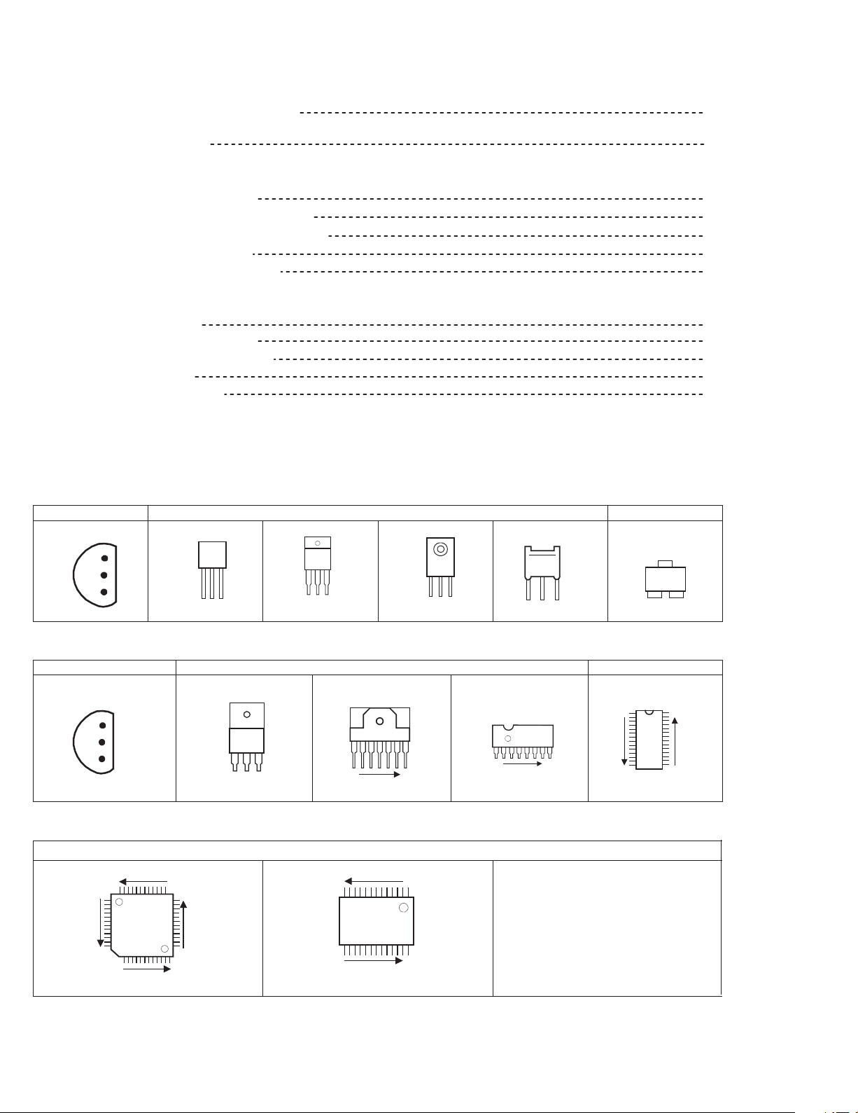
SEMICONDUCTOR SHAPES
TRANSISTOR
BOTTOM V IEW
E
C
B
ECB
BCE
(G)(D)(S )
FRONT VI EW
ECB
ECB
2-2
2-3
2-5
2-15
2-17
2-19
2-20
2-21
2-23
2-24
2-25
2-26
TOP VIEW
CHIP TR
C
BE
IC
BOTTOM VIEW FRONT VIEW TOP VIEW
OUT
E
IN
IN OUTE
1 N
1 N
CHIP IC
TOP VIEW
N
N
N
1
N
1
N
1
N
2-2
No.52136
Page 4
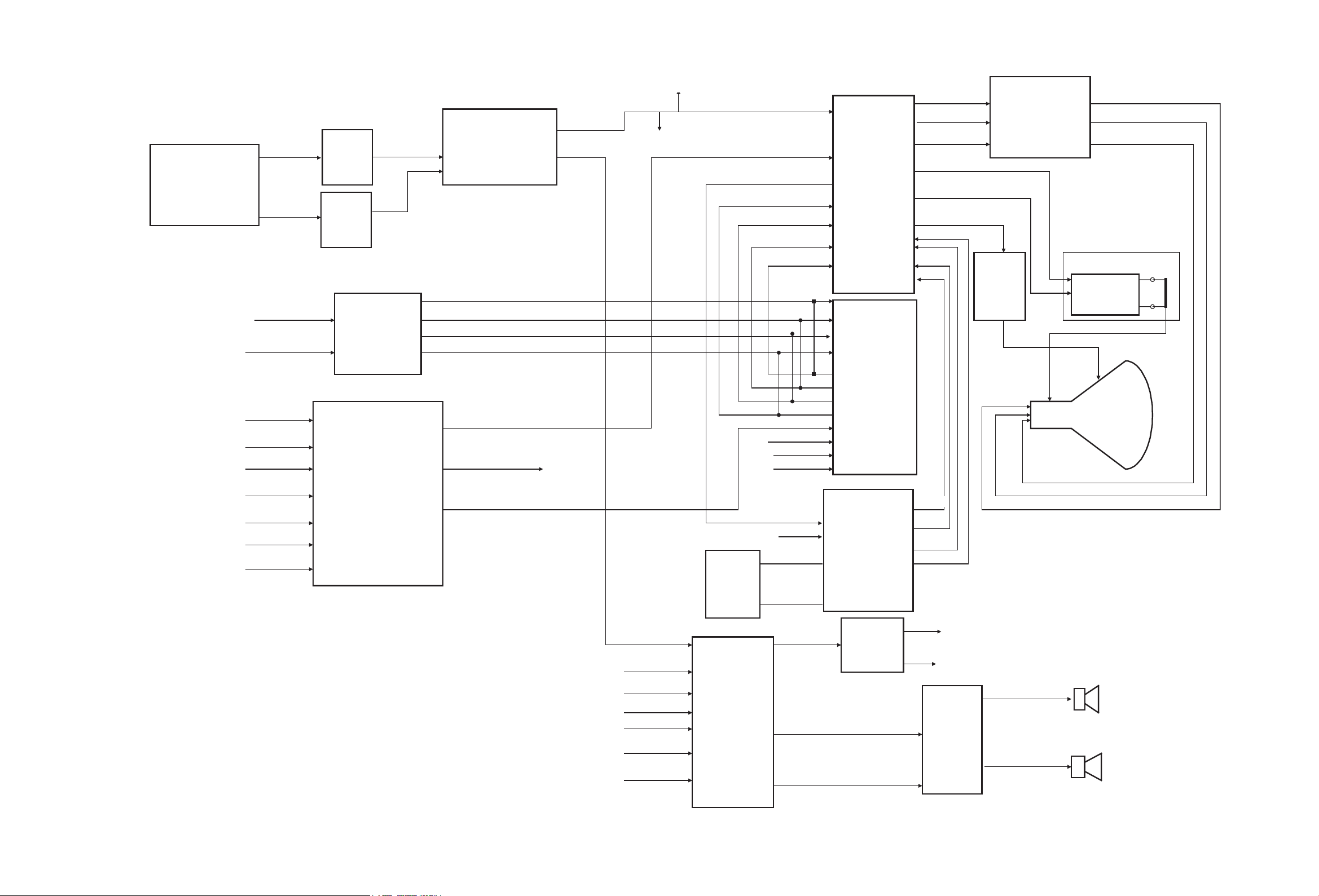
BLOCK DIAGRAM
AV-28GT1BJF, AV-28GT1BUF
AV-28GT1SJF, AV-28GT1SUF
AV-28GT10UF
AV-28GT1BJF, AV-28GT1BUF
AV-28GT1SJF, AV-28GT1SUF
AV-28GT10UF
TU200
38.9MHz-TV TUNER
SC1_RGB
SC2_RGB/DVD/DVB
Video
Sound
Z200
SAW
Filter
Z202
SAW
Filter
IC205
R
G
B
FB
IC206
CVBS
QSS
SC3_V_OUT
SC1_V_OUT
R
G
B
FB
IC200
VDP313XY
PIP
R
G
B
RGB AMPLIFIER
Horizontal
IC900
R
G
B
Vertical Stage
IC600
Yoke
SDA
SCL
SC1
SC2
IF
SVHS-Y
SC3
IC201
VIDEO SW
EXT_CVBS/Y
SC2_V_OUT
TO_PIP
SCL
SDA
SC1
SC2
FRONT/SC3
DVD/DVB/BAV
SCL
SDA
SYNC
TV_LINK
IC502
(E2PROM)
IC700
CVBS_TEXT
SDA
SCL
IC500
(MicroController)
IC704
L
R
CRT
OSD_R
OSD_G
OSD_B
OSD_FBL
L
Headphone
R
8 ohm
12W
IC301
AUDIO
AMPLIFIER
8 ohm
12W
No.52136
2-3 2-4
No.52136
Page 5
AV-28GT1BJF, AV-28GT1BUF
AV-28GT1SJF, AV-28GT1SUF
AV-28GT10UF
AV-28GT1BJF, AV-28GT1BUF
AV-28GT1SJF, AV-28GT1SUF
AV-28GT10UF
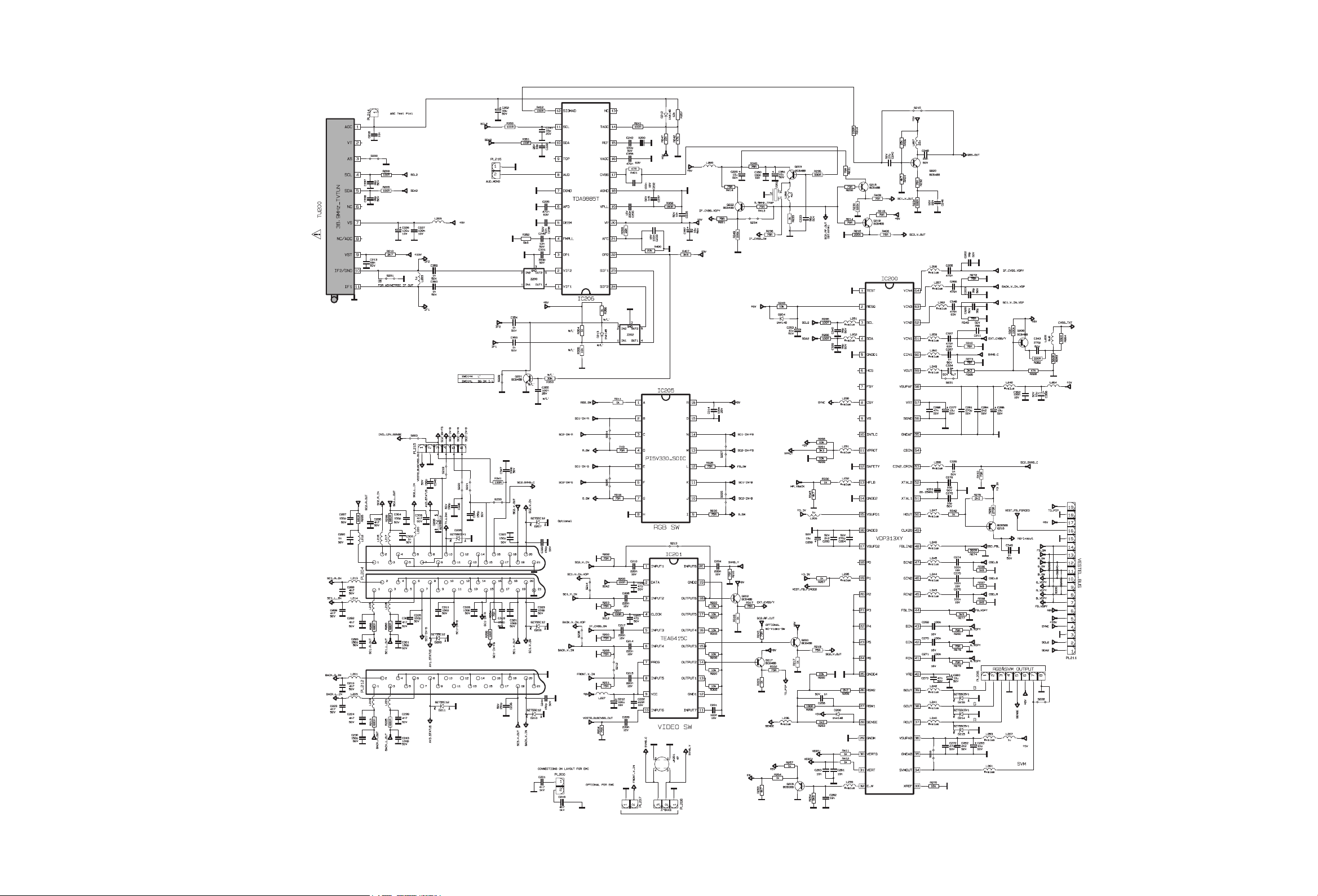
CIRCUIT DIAGRAMS
MAIN PWB CIRCUIT DIAGRAM [1/5]
MAIN PWB
VE-20120603
VE-20120602
VE-20127797
VE-20127793
(1/5)
(AV-28GT1BJF, AV-28GT1SJF)
(AV-28GT1BUF/A, AV-28GT1SUF/A)
(AV-28GT1BUF/B, AV-28GT1SUF/B, AV-28GT10UF)
(AV-28GT1BUF/C, AV-28GT1SUF/C)
No.52136 No.52136
2-5
CRT SOCKET PWB
SIDE CONTROL PWB
2-6
Page 6

MAIN PWB CIRCUIT DIAGRAM [2/5]
LED PWB
SIDE CONTROL
PWB
LED PWB
AV-28GT1BJF, AV-28GT1BUF
AV-28GT1SJF, AV-28GT1SUF
AV-28GT10UF
AV-28GT1BJF, AV-28GT1BUF
AV-28GT1SJF, AV-28GT1SUF
AV-28GT10UF
MAIN PWB (2/5)
VE-20120603
VE-20120602 (AV-28GT1BUF/A, AV-28GT1SUF/A)
VE-20127797 (AV-28GT1BUF/B, AV-28GT1SUF/B, AV-28GT10UF)
VE-20127793 (AV-28GT1BUF/C, AV-28GT1SUF/C)
(AV-28GT1BJF, AV-28GT1SJF)
No.52136
2-7 2-8
DIFFERENCE LIST
AV-28GT1BJF
AV-28GT1SJF
AV-28GT1BUF/A
AV-28GT1SUF/A
AV-28GT1BUF/B
AV-28GT1SUF/B
AV-28GT10UF
AV-28GT1BUF/C
AV-28GT1SUF/C
MAIN PWB
VE-20120603
VE-20120602
VE-20127797
VE-20127793
No.52136
IC 500 IC 502
VE-20139901
VE-20139901
VE-20137151
VE-20139902
VE-20120620
VE-20120611
VE-20124093
VE-20126316
Page 7

MAIN PWB CIRCUIT DIAGRAM [3/5]
AV-28GT1BJF, AV-28GT1BUF
AV-28GT1SJF, AV-28GT1SUF
AV-28GT10UF
AV-28GT1BJF, AV-28GT1BUF
AV-28GT1SJF, AV-28GT1SUF
AV-28GT10UF
SIDE CONTROL
PWB
SIDE CONTROL PWB
SIDE CONTROL PWB
MAIN PWB (3/5)
VE-20120603
VE-20120602
VE-20127797
VE-20127793
(AV-28GT1BJF, AV-28GT1SJF)
(AV-28GT1BUF/A, AV-28GT1SUF/A)
(AV-28GT1BUF/B, AV-28GT1SUF/B, AV-28GT10UF)
(AV-28GT1BUF/C, AV-28GT1SUF/C)
No.52136 No.52136
2-9 2-10
Page 8

MAIN PWB CIRCUIT DIAGRAM [4/5]
AV-28GT1BJF, AV-28GT1BUF
AV-28GT1SJF, AV-28GT1SUF
AV-28GT10UF
AV-28GT1BJF, AV-28GT1BUF
AV-28GT1SJF, AV-28GT1SUF
AV-28GT10UF
CRT
MAIN PWB
VE-20120603
VE-20120602
VE-20127797
VE-20127793
(4/5)
(AV-28GT1BJF, AV-28GT1SJF)
(AV-28GT1BUF/A, AV-28GT1SUF/A)
(AV-28GT1BUF/B, AV-28GT1SUF/B, AV-28GT10UF)
(AV-28GT1BUF/C, AV-28GT1SUF/C)
CRT SOCKET
PWB
No.52136
2-11 2-12
No.52136
Page 9

MAIN PWB CIRCUIT DIAGRAM [5/5]
AV-28GT1BJF, AV-28GT1BUF
AV-28GT1SJF, AV-28GT1SUF
AV-28GT10UF
AV-28GT1BJF, AV-28GT1BUF
AV-28GT1SJF, AV-28GT1SUF
AV-28GT10UF
AC INPUT
DEG.COIL
MAIN PWB
VE-20120603
VE-20120602
VE-20127797
VE-20127793
No.52136 No.52136
(5/5)
(AV-28GT1BJF, AV-28GT1SJF)
(AV-28GT1BUF/A, AV-28GT1SUF/A)
(AV-28GT1BUF/B, AV-28GT1SUF/B, AV-28GT10UF)
(AV-28GT1BUF/C, AV-28GT1SUF/C)
2-13
2-14
Page 10

CRT SOCKET PWB CIRCUIT DIAGRAM
AV-28GT1BJF, AV-28GT1BUF
AV-28GT1SJF, AV-28GT1SUF
AV-28GT10UF
AV-28GT1BJF, AV-28GT1BUF
AV-28GT1SJF, AV-28GT1SUF
AV-28GT10UF
CRT SOCKET PWB
VE-20121506
No.52136
MAIN PWB
2-15
MAIN PWB
2-16
No.52136
Page 11

SIDE CONTROL PWB CIRCUIT DIAGRAM
AV-28GT1BJF, AV-28GT1BUF
AV-28GT1SJF, AV-28GT1SUF
AV-28GT10UF
AV-28GT1BJF, AV-28GT1BUF
AV-28GT1SJF, AV-28GT1SUF
AV-28GT10UF
MAIN PWB
MAIN PWB
MAIN PWB
MAIN PWB
SPEAKER
LEFT
SPEAKER
RIGHT
SIDE CONTROL PWB
VE-20120893
No.52136 No.52136
2-17
2-18
Page 12

AV-28GT1BJF, AV-28GT1BUF
AV-28GT1SJF, AV-28GT1SUF
AV-28GT10UF
AV-28GT1BJF, AV-28GT1BUF
AV-28GT1SJF, AV-28GT1SUF
AV-28GT10UF
LED PWB CIRCUIT DIAGRAM SWITCH PWB CIRCUIT DIAGRAM
LED PWB
VE-20119110
MAIN PWB
No.52136
2-19
2-20
No.52136
Page 13

AV-28GT1BJF, AV-28GT1BUF
AV-28GT1SJF, AV-28GT1SUF
AV-28GT10UF
AV-28GT1BJF, AV-28GT1BUF
AV-28GT1SJF, AV-28GT1SUF
AV-28GT10UF
PATTERN DIAGRAMS
MAIN PWB PATTERN
FRONT
No.52136 No.52136
2-21
2-22
Page 14

AV-28GT1BJF, AV-28GT1BUF
AV-28GT1SJF, AV-28GT1SUF
AV-28GT10UF
AV-28GT1BJF, AV-28GT1BUF
AV-28GT1SJF, AV-28GT1SUF
AV-28GT10UF
CRT SOCKET PWB PATTERN SIDE CONTROL PWB PATTERN
TOP
TOP
No.52136
2-23
2-24
No.52136
Page 15

AV -28GT1BJF , AV-28GT1BUF
AV-28GT1SJF, AV-28GT1SUF
AV-28GT10UF
AV-28GT1BJF, AV-28GT1BUF
AV-28GT1SJF, AV-28GT1SUF
AV-28GT10UF
LED PWB PATTERN POWER SWITCH PWB PATTERN
FRONT
TOP
No.52136 No.52136
2-25
2-26
WPC0309
DP8080
Page 16

VICTOR COMPANY OF JAPAN, LIMITED
AV & MULTIMEDIA COMPANY VIDEO DISPLAY CATEGORY 12, 3-chome, Moriya-cho, kanagawa-ku, Yokohama, kanagawa-prefecture, 221-8528, Japan
(No.52136)
Printed in Japan
WPC
 Loading...