

Page 1

AV-28BT8ENS / AV-28BT8ENB / AV-28BT80EN
AV-28BT8EPS / AV-28BT8EPB / AV-28BT80EP
AV-28BT8EES / AV-28BT8EEB/ AV-28BS88EN
SERVICE MANUAL
COLOUR TELEVISION
AV-28BT8ENS / AV-28BT8ENB
AV-28BT80EN / AV-28BT8EPS
AV-28BT8EPB / AV-28BT80EP
AV-28BT8EES / AV-28BT8EEB
AV-28BS88EN
CONTENTS
!
SPECIFICATIONS
! SAFETY PRECAUT IONS ・・・・・・・・・・・・・・
!
FEATURES
!
MAIN DIFFERENCE LIST ・・・・・・・・・・・・・・
1
・・・・・・・・・・・・・・・・・・・・・・・・・・
・・・・・・・・・・・・・・・・・・・・・・・・・・
・・・・・・・・・・・・・・・・・・・・・・・・・・・・・・・・・・・・・・・・・・・・・・・・・・・・
・・・・・・・・・・・・・・・・・・・・
・・・・・・・・・・・・・・・・・・・・
・・・・・・・・・・・・・・・・・・・・・・・・・・・・・・・・・・・・・・・・
・・・・・・・・・・・・・・4
・・・・・・・・・・・・・・・・・・・・・・・・・・・・
・・・・・・・・・・・・・・5
・・・・・・・・・・・・・・・・・・・・・・・・・・・・
COPYRIGHT © 2002 VICTOR COMPANY OF JAPAN, LTD.
2
5
!
SPECIFIC SERVICE INSTRUCTIONS
! SERVICE ADJUSTMENTS・・・・・・・・・・・・
!
PARTS LIST
★
OPERATING INSTRUCTIONS
★
STAND ARD CIRCUIT DIAGRAM
・・・・・・・・・・・・・・・・・・・・・・・
・・・・・・・・・・・・・・・・・・・・・・・
・・・・・・・・・・・・・・・・・・・・・・・・・・・・・・・・・・・・・・・・・・・・・・
・・・・・・・・・・・・ 11
・・・・・・・・・・・・・・・・・・・・・・・・
・・・・
・・・・
・・・・・・・・
・・・・・・
・・・・・・
・・・・・・・・・・・・
No.520 57
Jul. 200 2
6
23
2- 1
Page 2

A
V-28BT8ENS / AV-28BT8ENB / AV-28BT 80EN
A
A
V-28BT8EPS / AV-28BT 8EPB / AV-28BT80EP
V-28BT8EES / AV-28BT 8EEB/ AV-28BS88EN
SPECIFICATIONS
Content
Item
Dimensions ( W
Mass 33.2 kg
TV RF Syste m B/G B/G , L /L ’ D/K , K1 B/G
Colour Sy st em
Sound System German + NICAM
Teletext System
Receiving Frequency
Intermediate Fr equency
Colour Sub Carrier Fr eq.
Power Input AC 220V ~240V , 50Hz
Power Consumpti on
Aerial Input Term 75 Ωun ba l anc ed, Coax ial
Picture Tube Size Visi ble si ze : 66cm , M eas ured dia gon al ly
Hi g h V o lt ag e 30 .3 kV 30 .3 kV 30 .3 kV 29 .6 kV
Speaker 5.7 cm×16cm Oval type×2
Au dio Output 10 W ×2
Input
Output
Input Terminal
Output Terminal
Remote Control Unit VE -3 00 177 63 (RM-C 11 00) , (A A/R0 6 dry bat ter y×2)
××××H××××
D ) 77 x 58 x 48 cm
TV Mode PAL PAL / SE CAM PAL / SE CAM PAL
Video Mode PA L / SE CAM / NTSC 3 .58 / NTSC 4 .43 (EP/EE MODEL S)
VHF(VL)46 .25 MH z ~ 1 68. 25 MH z
(VH)17 5.2 5MH z ~ 46 3.2 5MH z
UHF 471.2 5MHz ~ 86 3.25MHz
CATV S01-S4 1 & S7 5-S79
VIF Carrier 38 .9MHz (B/G , D/K , L) / 3 3.9MHz(L’)
SIF C ar rier 33.4 MHz ( 5 .5MHz:B/G) / 32.9MHz (6 .0MHz:D/K) / 32 .4MHz (6.5MHz:L) / 40.4MHz ( 6 .5MH z:L’)
PAL 4.43MHz
SE CAM 4.43MHz
NT S C 3.58MHz / 4.43MHz
Vide o 1V p-p, 75 Ω
S/V ideo Y : 1Vp-p Pos it ive
Au di o(L/ R)50 0mVrms, High Imp ed an ce
Vide o 1V p-p 7 5Ω
Au di o(L/ R)50 0mVrms, Low Im pe da nce
Rear Sid e AV 1 (Vi d eo/A udi o/R GB)
Front Side AV 3 (Vi d eo/A udi o)
Front Side
Rear Sid e AV 1 (Vi d eo/A udi o)
AV -2 8BT 8 EN S
AV -2 8BT 8 EN B
AV-28BT 8 0EN
PAL / N TSC 3.58 / NTSC 4 .43 (EN MODELS)
Fast ext / Topte xt
11 4W (Max)
4W (Sta nd by)
C : 0 .2 86V p-p
AV 2 (Vi d eo/A ud io/S-VH S)
Headphon e jac k (Stere o mini j ack 3.5φ)
AV 2 ( Vi d eo/A ud i o) (S elect ed TV,A V1 or AV 3)
AV- 28 BT8 EPS
AV- 28 BT8 EPB
AV - 28 BT8 0E P
11 4W (MAX)
4W (Sta nd by)
AV- 28 BT8 EES
AV- 28 BT8 EEB
11 4W (MAX)
4W (Sta nd by)
13 5W (Max)
4W (Sta nd by)
AV-28B S88EN
De sign & specificatio ns ar e subje ct to cha nge wi thout notice.
2
No.52057
Page 3
A
V-28BT8ENS / AV-28BT8ENB / AV-28BT 80EN
A
P
A
V-28BT8EPS / AV-28BT 8EPB / AV-28BT80E
V-28BT8EES / AV-28BT 8EEB/ AV-28BS88EN
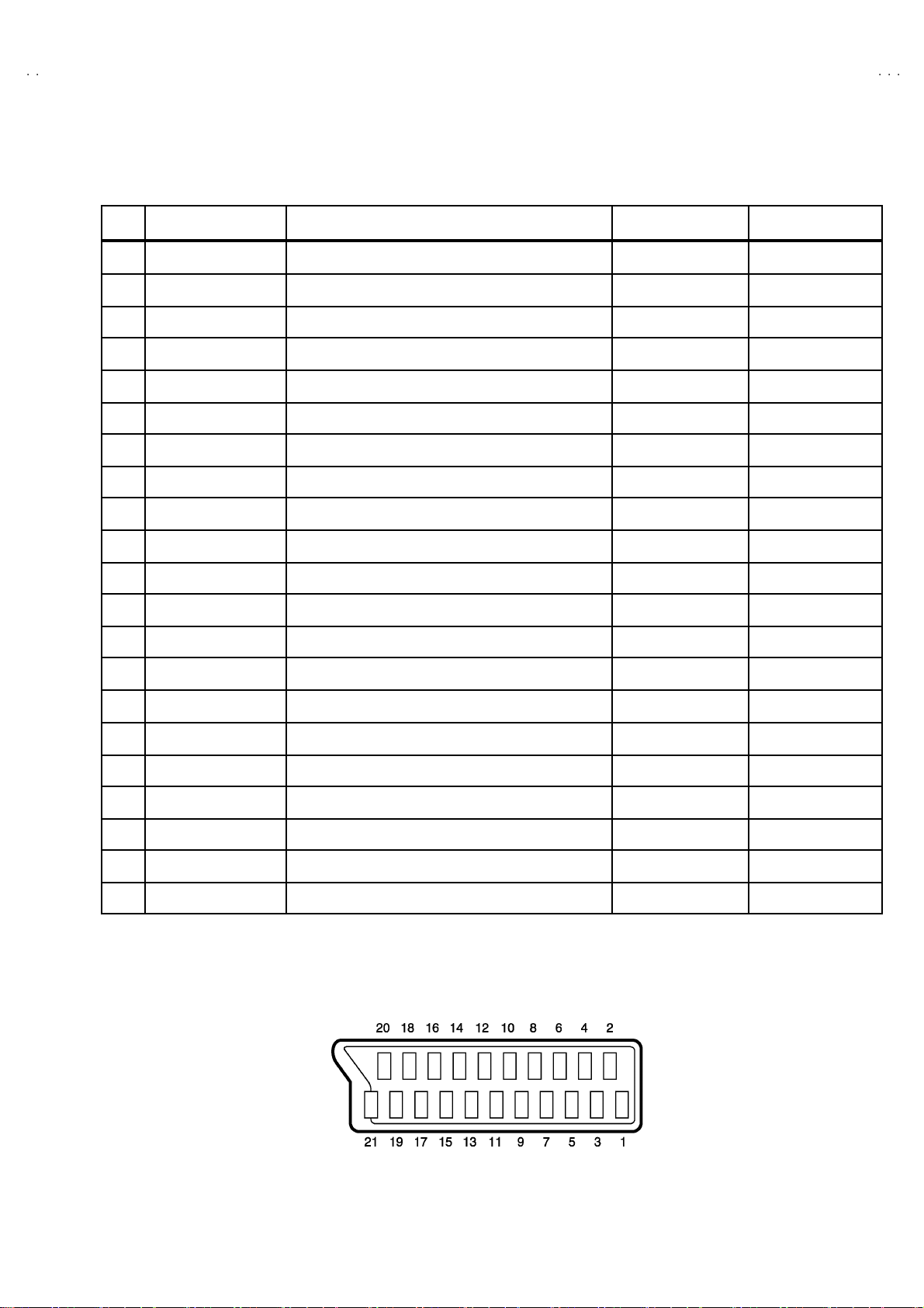
■■■■21-pin Euro connector (SCART socket) : AV-1 / AV-2
(P-P= Peak to Peak, S-W= Sync tip to white peak, B-W= Blanking to white peak)
Pin
Signal Designation Matching Value AV-1 AV-2
No .
1 AUDIO R out put 50 0mVrms( Nomi na l),L ow im pedan ce
2 AUDIO R input 500mVrms(Nominal),High impedance ○○
3 AUDIO L o utp ut 50 0m Vr ms( N omina l) ,L ow impe danc e
4 AUDIO G ND
5 GND (B) ○○
○
(TV OUT)
○
(TV OUT)
○○
○
(TV/LIN E OUT)
○
(TV/LIN E OUT)
6 AUDIO L input 500mVrms(Nominal), High imp edance
B-W
7B input
FUNCTON SW
8
(SLOW SW)
9 GND (G)
10 - NC -
11 G in put
12
- NC -
13 GND (R)
14 GND (YS) ○ NC
15 R / C input
16 Ys i n put L ow : 0 – 0. 4, Hi g h : 1 - 3 V, 75Ω○NC
17 GND(VIDEO output)
18 GND(VIDEO input) ○○
19 VID EO output
20 VIDEO / Y inp ut 1V
70 0mV
Low : 0-3V, High : 8-12V, High impedance
70 0mV
R : 700mV
C : 300mV
1V
, 75Ω○
B-W
, 75Ω○
B-W
, 75Ω
P-P
, 75Ω
S-W
(Negative going sync), 75Ω
S-W
(Negative going sync), 75Ω○○
○○
NC
○
○○
○○
○
(R/C)
○○
○
(TV)
NC
NC
○
(only C)
○
(TV/LINE OUT)
21 COMMON G ND
○○
[Pin assignment]
No.52057
3
Page 4

A
V-28BT8ENS / AV-28BT8ENB / AV-28BT 80EN
A
A
V-28BT8EPS / AV-28BT 8EPB / AV-28BT80EP
V-28BT8EES / AV-28BT 8EEB/ AV-28BS88EN
SAFETY PRECAUTIONS
1. The des ign of th is pr od uc t conta in s sp eci al hardware, many
circuit s and components specially for safety pur poses. For
con tinu ed pr ot ection, n o chang es s h ou ld b e ma de to the o rig inal
d esi gn un l ess a uth or i zed i n w ritin g by th e manufact ur er.
Replac emen t p ar ts must b e id ent ic al to thos e u sed in th e origi n al
ci rcu it s . Se r vic e sh ou ld be pe rf ormed by qua lified perso nn el
on ly.
2. Alte r ati on s of t he desig n or ci r cui tr y of t he pr od ucts s h ould not be
made. Any design alterations or additions will void th e
manufact urer 's warr a nt y and w i ll f urther rel i eve t he manufacturer
of r esp ons ib ili ty for perso na l injur y or p roperty dam ag e r esult ing
th erefr om.
3. Many el ectric al and mech ani ca l p ar ts in th e pr od ucts ha v e
special safety-related characteristics. T hese charact eristics are
oft en no t e viden t f r om vi sual i nspecti on n or ca n t he pr o tec t io n
aff or de d by th em necessari l y be ob tain ed b y us ing replac emen t
com po ne nts ra ted for hig he r vol tag e, watt ag e, etc. Rep lacem en t
p arts wh ic h ha ve these sp eci al s afet y ch ar act erist ics are
ide ntified in the parts l ist of Service manua l. El ec trical
components having su ch features ar e identified by shading
on t he sch e matics and by (!!!! ) on the parts list in Service
manual. The us e of a s ub stitute r ep lacem en t w hi ch do es n ot
h ave the sam e saf ety ch ar ac t er ist ics as t he r eco mmen de d
replac em ent par t s h ow n in th e p ar ts l i st of S er vi ce manual m ay
cause shock, fire, or other hazards.
4. Don't shor t between the LIVE s ide ground and ISOL ATED
(NEUTRAL) side ground or EARTH side ground when
repairing.
Some model's power circuit is partly different in the GND. The
diff er enc e of the GND i s s h own b y the LI VE s ide G ND, th e
ISO LATE D(NEUTRAL) sid e GND a nd EA RTH side GN D. Don' t
sh ort b etwee n the L IVE side GND a nd ISOLATE D(N EU TRAL)
si de GN D or EA RTH si de GN D an d ne ver meas ur e with a
measu r in g app ar atu s (os c illos c ope et c.) th e LIV E sid e GND an d
ISO LATED(NEUTRAL) side GND or EARTH side GND at the
same time.
If above note will not be kept, a fuse or any parts will be broken.
5. If any repair has been made to the chassis, it is recommended
th at t he B1 set ti ng should b e ch ec ke d or adj u ste d ( Se e
ADJUST MENT OF B 1 POWE R SUPPL Y).
6. The hi gh volta ge app lie d t o th e pi ctu r e tu be mu st con for m wit h
th at s p eci fi ed i n S er vic e man ual. E xcessive h i gh voltage ca n
cau s e an incr e ase in X-R ay emis si on , ar cing an d poss ib le
component damage, therefore operation under excessive high
voltage conditions should be kept to a minimum, or should be
preve nt ed. If s ever e arc ing occurs, r em ove t he AC pow er
immed i ate l y and determine the ca us e b y visua l insp ect ion
(inc orrect in stallat ion, cr acke d or m elte d high vo lt age har n es s,
p oor so ld er ing, et c .) . T o m aint ain the p r ope r minimu m le vel of
sof t X- Ray em i ss ion, c omp on en ts i n th e hi gh voltage ci r cui tr y
includ ing t he pict ure tu be must b e t he e x act rep lacem e nts or
alte rnat i ves ap prove d b y th e ma nuf act urer of th e c om plet e
product.
7. Do not c hec k hi gh volt age by dr aw ing an arc. U se a high vol t age
meter or a high v ol tag e pr ob e wi t h a V TVM . Di scha rg e th e
picture tube before attempting meter connection, by connecting
a cl ip lead to th e gr ou nd frame and c onn ec ti n g th e other end of
the lead through a 10kΩ 2W resi stor to the an od e butt on .
8. When se r vic e is r equ ired, ob serv e th e or i ginal lea d dr ess. Ex tr a
prec aut ion sh ou ld b e g i ven t o assur e cor r ect lea d dress in th e
high vol tag e cir cuit a rea. W her e a s hor t cir cuit has occu rr e d,
th ose co mp on ent s tha t indic a te ev idence of ove r hea ting s ho ul d
b e replace d. A lways use th e ma nuf ac t ur er 's r ep l acemen t
components.
9. Isolation Check
(Safety for Electrical Shock Hazard)
Af ter re- ass emb l ing th e p r odu ct, alway s per f orm an isolat ion
ch ec k on the expo s ed me tal p ar ts of t he cabin et ( a nte nn a
ter mina ls, vid eo /audi o inpu t and ou tput t er min als, Con trol kn obs,
metal cabinet, screwheads, earphone jack, control shafts, etc.)
to be su re th e p r odu ct is s af e t o o pe r ate with ou t d an ger of
elect ri cal shoc k.
(1) Di electric Strength Test
The isolation be tw een the AC pr imary ci rcu i t an d all me tal p ar ts
exp osed t o th e us er, p ar ti cul ar ly an y expos ed met al part h avi ng a
retu rn p ath to t he chas s is should wi ths tan d a v olt age of 3 000 V
AC (r.m.s.) for a period of one sec ond.
(. . . . Withstan d a vo lt ag e of 1 10 0V AC ( r .m. s.) t o an ap pl i anc e
rate d up to 12 0V , an d 3 00 0V AC (r.m. s.) to an ap pliance r at ed
200V or more, for a period of one second.)
This meth od of test requires a t est equi pmen t not gen erally fou nd
in t he ser vic e tr ad e.
(2) Leakage Current Check
Plug th e A C line c ord direct l y in to the AC outlet (d o n ot use a lin e
isolatio n tr ansf or mer du r in g thi s c h eck.) . Usin g a " Lea kage
Curr ent Teste r", meas ur e th e lea kag e cu rrent f rom each exp osed
metal part of the ca bi ne t, part icu l arly any e xpos ed me tal p ar t
h avi ng a r e tur n path to t he chassis , to a kn own go od ea rt h
ground (wa ter pip e, etc.). An y leak a ge cur r en t mus t n ot exceed
0.5mA AC (r.m.s.).
Howeve r, in tr op ic al area , th is must no t exceed 0.2 mA AC
(r.m.s.).
"""" Alternate Check Method
Plug th e A C line c ord direct l y in to the AC outlet (d o n ot use a lin e
isolatio n tr an sformer dur i ng t hi s che ck.) . U se an AC vo lt me ter
h avi ng 1 00 0 oh ms per volt or more sens it ivi ty in the fo llow i ng
manner. Connec t a 1500Ω 10W res ist or para lle le d b y a 0.1 5µF
AC-type c apa cit or bet ween an expo s ed met al pa rt a nd a known
g ood e ar th gro un d ( water pipe, etc.) . M eas ure th e A C vo lt ag e
acr oss th e res ist or w ith th e AC voltmeter. M ove the resi stor
con nec ti on to e ac h exp ose d me tal par t, p art i cul ar ly any exp osed
metal part havi n g a r etu rn pat h to the c h assis, an d measu r e th e
AC vol tag e ac ro ss the res ist or . No w , re ver s e th e pl u g in th e AC
ou tl et and re pe at eac h mea surem en t. An y v olt ag e me asu re d
must no t exc eed 0.7 5V AC (r .m.s.). This c orre sponds to 0.5mA
AC (r.m.s.).
Howeve r, in tropica l area, this must not exce ed 0 .3V AC ( r.m. s.) .
This corresponds to 0.2mA AC (r.m.s.).
AC VOLTMETER
(HAVING 1000 Ω/V,
OR MOR E SENSIT IVITY)
0.15μF AC -T YPE
PLACE THIS PROBE
1500 Ω 10W
GOOD EARTH GROUND
ON E A C H EX PO SE D
ME T AL PA R T
4
No.52057
Page 5
A
A
P
A
FEATURES
)
(
)
"
10 0 pr o gr am m ers fr om V H F, UHF b and s or ca bl e ch an nels can
b e pres et.
"
It has two Euroconnector sockets for ext ernal devic es (such as
vi de o r eco rder , vi d eo ga mes , audio set, etc.)
" St er eo s ound s ystem s ( N icam + Ger m an ) are avai l a ble.
"
APS ( Au tomat ic Progra mming Syst em)
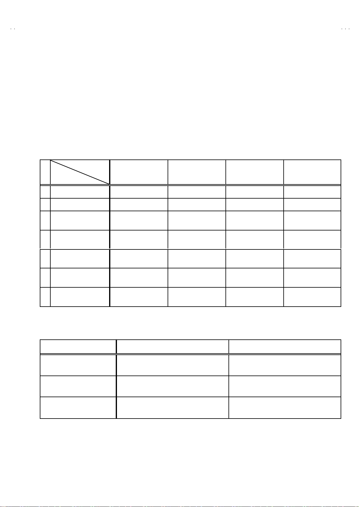
MAIN DIFFERENCE LIST
V-28BT8ENS / AV-28BT8ENB / AV-28BT 80EN
V-28BT8EPS / AV-28BT 8EPB / AV-28BT80E
V-28BT8EES / AV-28BT 8EEB/ AV-28BS88EN
Model Name
!!!!
Part Name
MAIN PWB VE-20101577 VE-20101576 VE-20101622 VE-20101578
INST RUCT ION
!
BOOK
!
FRON T CABINET
!
REAR COVER
!
LENS
! RATING LABEL
CAR TON BO X
AV -2 8B T 8 EN S
AV -2 8B T 8 EN B
AV-2 8B T80EN
VE-50028493 VE-50028296 VE-50028326 VE-50028511
VE-20082289(ENS)
VE-20081489(ENB)
VE-20082289(EN)
VE-20084616(ENS)
VE-20069018(ENB)
VE-20084616(EN)
VE-20069218
(ENS/ENB
VE-20096162(EN)
VE-20102137(ENS)
VE-20102147(ENB)
VE-20102144(EN)
VE-50028496(ENS)
VE-50028502(ENB)
VE-50028500(EN)
AV -2 8B T 8 EP S
AV -2 8B T 8 EP B
AV-2 8B T80EP
VE-20082289(EPS)
VE-20081489(EPB)
VE-20082289(EP)
VE-20084616(EPS)
VE-20069018(EPB)
VE-20084616(EP)
VE-20069218
EPS/EPB
VE-20096162(EP)
VE-20101937(EPS)
VE-20101939(EPB)
VE-20101934(EP)
VE-50028423(EPS)
VE-50028424(EPB)
VE-50028221(EP)
AV -2 8B T 8 EE S
AV -2 8B T 8 EE B
VE-20082289(EES)
VE-20081489(EEB)
VE-20084616(EES)
VE-20069018(EEB)
VE-20069218 VE-20096162
VE-20101919(EES)
VE-20101915(EEB)
VE-50028218(EES)
VE-50028216(EEB)
VE-20082289
VE-20086416
VE-20102141
VE-50028498
CABINET COLOUR
AV-2 8B S88E N
Mo del Name
FRONT CABINET & REAR COVER LENS
AV-2 8BT8 ENS
AV-2 8BT8 EP S
SILVER BLACK
AV-2 8BT8 EE S
AV-2 8BT8 ENB
AV-2 8BT8 EP B
BLACK BLACK
AV-2 8BT8 EE B
AV-28BT8 0EN
AV-28BT8 0EP
SILVER SILVER
AV-28BS88EP
No.52057
5
Page 6

A
V-28BT8ENS / AV-28BT8ENB / AV-28BT 80EN
A
A
V-28BT8EPS / AV-28BT 8EPB / AV-28BT80EP
V-28BT8EES / AV-28BT 8EEB/ AV-28BS88EN
SPECIFIC SERVICE INSTRUCTIONS
DISASSEMBLY PROCEDURE
REMOVING THE REAR COVER
1. Unplug t he power c ord.
2. Remove the 8 screws marked A as show n in t he Fig. 1.
3. Remove the 4 screws marked B around the AV TERMINAL
BOA RD.
4. Withdraw the rear co ver to ward y ou .
REMOVING THE AV TERMINAL BOAR D
" Removing the rear cover.
1. Remove th e 2 s cr ew s m ar ke d C f asten ed th e AV TERMINAL
BOA RD.
2. Remove th e AV TERMI NAL BOARD .
REMOVING THE MAIN PWB
"
Removing the rear cover.
" Removing the AV TERMINAL BOAR D.
1. Remov e th e 3 scr ew s m ar ked D as shown i n t he F ig.1 .
2. Slight ly rais e t he both s ides of the ch assi s b y h and an d w ithd raw
th e M AIN PW B bac kw ar d.
(If n ecess ary, ta ke off the wir e clamp, connectors etc.)
REMOVING THE SPEAKER
"
Removing the rear cover.
1. Remov e t he 4 scr ew s m ar ked E, and remove speake r as s h own
in Fig. 1.
2. Remove th e sp eak e r .
CHECKING THE PW BOARD
To c h eck the bac k s ide of th e PW B oard.
1) Pull o ut the PW B oar d. ( R ef er to R EM OV ING THE MA IN
PWB).
2) Erec t the PW B oar d vertic ally so t ha t you c an easi ly ch eck
th e b ack side of th e PW B oard.
[CAUTION]
" When e recting t he PW Board, be careful so t hat there will be no
con tact in g with ot her PW Boar d.
" Be for e tur n in g on pow er , ma ke s ur e t ha t the wire connector is
properly con nec ted .
" When co ndu cting a ch eck w ith p ower su ppl ied, b e sure to c onfi r m
th at t he CRT E AR TH WI RE (BRAIDED AS S’Y) is co nne cted t o
th e C RT SOCKE T PW b oard.
WIRE CLAMPING AND CABLE T YING
1. Be sure to cla mp th e wire.
2. Never r emove the c abl e ti e u sed f or t ying the wi res togethe r.
Sh ould it be inadve rt ent ly r em ove d, be s u r e to ti e th e wir es w it h
a n ew c abl e ti e.
REMOVING THE FRONT AV & HEADPHONE PWB
" Removing the rear cover.
"
Removi ng th e MAIN PWB.
1. Remov e th e 2 scr ew s m ar ked F.
2. Remove th e FR ONT AV & HE ADPHON E PWB.
REMOVING THE FRONT CONT ROL PWB
"
After removing the rear cover.
1. Remove th e MAIN PW B AS S’Y.
2. Remove th e 5 screws marked G, a nd r em o ve th e FRONT
CONTROL PWB.
6
No.52057
Page 7

A
V-28BT8ENS / AV-28BT8ENB / AV-28BT 80EN
A
P
A
V-28BT8EPS / AV-28BT 8EPB / AV-28BT80E
V-28BT8EES / AV-28BT 8EEB/ AV-28BS88EN
A
(× 8)
B
(×4)
AV TERMINAL BOARD
REAR COVER
(×3)
D
MAIN PWB
BAS E BOARD
REAR SIDE
AV TERMINAL BOARD
C
(×2)
E
(×4)
CRT
SP EAKE R
F
G
(× 5)
FRONT CABINET
(× 2)
FRONT AV &
HE ADPHONE PWB
FRONT CO NTROL
PWB
BB
Fig. 1
No.52057
7
Page 8

A
V-28BT8ENS / AV-28BT8ENB / AV-28BT 80EN
A
A
V-28BT8EPS / AV-28BT 8EPB / AV-28BT80EP
V-28BT8EES / AV-28BT 8EEB/ AV-28BS88EN
REPLACEMENT OF CHIP COMPONENT
! CAUTIONS
1. Avoid heating for more than 3 seconds.
2. Do not ru b t he el ect rodes an d t he r esis t p arts of th e patt ern.
3. W hen removi ng a c hip par t, mel t the s older ad equ ate ly.
4. Do not r euse a ch ip part afte r re mo vi ng it .
! SOLDERING IRON
1. Use a hi g h ins ulati o n s older ing iron with a t hin po in ted end of it .
2. A 3 0 w s older ing ir on is r ec omm ended for easil y rem oving par ts .
!
REPLACEMENT STEPS
1. How to remove Chip parts
####
Resi stors, ca pacitors, etc
(1) As shown in t he f igure, pu sh the pa rt with tweezer s and
alte rnat el y mel t th e s older at each end.
(2) Shift with tweeze rs and r emo ve th e ch ip p ar t.
#### Trans isto rs, dio des, va ria ble r es istor s, etc
(1) Apply e xtra so ld er to ea ch le ad.
SOLDE R SOLDE R
2. How to install Chip parts
####
Resi stors, capacito rs , etc
(1) Apply sold er to th e pattern as ind icated in the fig ure.
(2) Grasp the c h ip p art with twee zer s and plac e i t on th e s ol d er.
The n hea t and melt th e so ld er a t b oth ends of the chi p par t.
#### Trans isto rs, dio des, va riable r es ist or s, et c
(1) Apply sold er to th e pattern as ind icated in the fig ure.
(2) Grasp th e ch ip part with t weeze rs and p lace it on th e solder .
(3) First solder lead A as indicated in the figure.
A
(2) As shown in t he f igure, pu sh the pa rt with tweezer s and
alte rnat el y mel t th e s older a t each le ad . Shi ft an d remove the
chip part.
(4) The n solder le ads B and C.
Note : A fter removing the part, remove remain ing so lder fro m the
pattern.
8
No.52057
C
A
C
B
B
Page 9

A
A
P
A
MEMORY IC REPLACEMENT
VALUE
VALUE
ITEM
MENU
MU T I NG
INFORMATION
COLOUR k
1. Memory IC
This model use a memory IC.
Thi s memo r y I C st or es d ata for pr op er op er ati o n of the video
an d d ef lection circu it s.
When replacing, be sure to use an IC containing this (initial
valu e) d ata.
2. Memory IC replacement procedure
(1) Power off
Switch of f t he p ow er an d disconnec t th e po we r co rd fr om
the wall outlet.
(2) Replace the memory IC
Init ial value must be en tered int o the new IC.
(3) Power on
Connect the power cord t o t he wall o utle t an d s witch on the
power.
V-28BT8ENS / AV-28BT8ENB / AV-28BT 80EN
V-28BT8EPS / AV-28BT 8EPB / AV-28BT80E
V-28BT8EES / AV-28BT 8EEB/ AV-28BS88EN
SE RVICE M ENU
Fig.1
SERVICE MENU SELECT KEY
(4) SERVICE MENU setting
1) Press MENU key and, while the displayed MENU
screen, press 4, 7, 2, 5 k ey on the remote co ntrol u ni t or
press MUTING key and INFORMATION key at the
simult aneously.
2) The SERV ICE M ENU scree n of Fi g.1 is d isplay ed .
3) Veri f y what to set in th e SER V IC E MEN U, and set
what ever i s nec e ssar y (Fig.1 ). Ref er to th e SE RVICE
ADJU STMENT for se ttin g.
4) Press the STANDARD key to exit SERVICE MENU.
(5) Rec eive channel setting
Refe r to th e OP ERATING I NSTRUCTIONS (USER’ S
GUIDE) a nd s et th e rece ive chan nels ( Chan n els Pr eset ) as
described.
(6) U ser setting s
Check the us er sett in g it em s ac c ordi ng to after page.
Where th ese d o no t a gr ee, refer to t he OPE RA T ING
INSTRUCT ION S (USER’S GUIDE) and set th e items as
described.
ITEM
SELECT(▲)
SELECT(-)
FUNCTION
POWER
NUMBER
STANDARD
ey
SELECT(+)
SELECT(▼)
Fig.2
No. 52057
9
Page 10

A
V-28BT8ENS / AV-28BT8ENB / AV-28BT 80EN
A
A
V-28BT8EPS / AV-28BT 8EPB / AV-28BT80EP
V-28BT8EES / AV-28BT 8EEB/ AV-28BS88EN
SETTING OF THE LAST MEMORY FOR SHIPMENT
■■■■ USER SETTING VALUES
Setting Item Setting Value Setting Item Setting Value
SOUND MENU FEATURE MENU
BA LANC E CEN TER SLEEP TIME R OFF
BA SS
↑
CHI LD LO CK OFF
TR EBL E
MODE STEREO AV-2 OUTPUT TV
EFFECT OFF
3D PANORAMA
(only A V- 28B S88EN )
PICTURE MENU INSTALL
BRIGHTNES S PROGRAMME
CONTRAST BAND
COLO UR CHA NNEL
SHAR PNESS SE ARCH
HUE (only NTSC)
PICTURE MODE AUTO STORE
■
SETT ING APS BIT IN SERVICE MENU
1) Enter ser vice menu in TV mode b y pressi ng “INFORMA TION ” a nd “ MUTI NG” ke ys s imul tan eous ly. S ervic e M en u wil l ap pea r.
2) Selec t TX1 (TEL ETEXT OPT IO N) b y pr essin g Up/Down keys o n remot e c ontrol un it.
3) Press the 7 key on remote control unit to set APS bit . (After this, bit 7 of TX1 will be “1”)
4) Press STANDARD key on remote c ont rol un it to exit service mode.
NOTE : DO NOT TURN OFF THE TV BY USING POWER B UTTON ON THE FRONT PANEL.
Thes e ad j ust a re aut om ati ca lly
restore d when APS bit in Se rvic e
menu is set .
The pr oc edu r e f or s e tti ng AP S
bit is described bellow.
↑
OFF
LANG UAGE ENGL ISH
Refer to the INSTRUCTION
BOO K.
FINE TUNING
10
No. 52057
Page 11

A
A
P
A
SERVICE ADJUSTMENTS
ADJUSTMENT PREPARATION
1. You ca n ma ke t he n e ce ssa ry adjust ments f or t his un it with
either the Remote Control Unit or With the adjustment tools
and par ts as given below.
2. Ad justment with the Remote Control Uni t is made on the
basis of the initial setting v alues, howev er, the new setting
values which set the screen to its optimum condition may
differ f rom t he initia l s ett ings.
3. Make sure t hat AC p ower is tu r ned o n correc tly.
4. Turn on the power for s et an d test eq ui p me nt bef ore use , and
start t he ad j ustment p r oced ures aft er waiting at leas t 30 m in ut es.
5. U nl ess o the r wise s pec if i ed, prepare t he mo st su it ab le r ecep tion
or inp ut si gn al for adjust ment.
6. N ever touch any ad justm en t parts wh ic h ar e n ot s p ecified in t he
list for this adjustment - variable resistors, transformers,
condensers, etc.
7. Pr es etting b efor e ad justmen t.
Unles s ot herwi se spec if ied in t he a dj ustme nt instruc t i ons, p r ese t
th e f ollowin g f unc ti ons with th e re mo te c ont ro l unit.
BRIGHTNES S
CONTRAST
COLO UR
SHAR PNESS
V-28BT8ENS / AV-28BT8ENB / AV-28BT 80EN
V-28BT8EPS / AV-28BT 8EPB / AV-28BT80E
V-28BT8EES / AV-28BT 8EEB/ AV-28BS88EN
CENTER
ADJUSTMENT EQUIPMENT
1. DC voltmeter (or digital voltmeter)
2. Signal g ener ator (P att ern g ener ator) [PAL/S ECAM/NTSC]
3. Remote control unit
MAIN PARTS LOCATIONS
HEAD PHONE J ACK
FRONT
VIDEO
RL
AUDIO.
LE D
REMOCO N
RECEIVER
ADJUSTMENT ITEM
!
SCR EEN ADJU ST MENT
! OSD HORIZONTAL POSITION ADJ USTMENT
!
IF ADJUSTM ENT
! AGC AUTO MATI CA LLY ADJUSTMENT
!
DEFLECTION CIRCUIT ADJUSTMENT
! GEO MET R Y MENU AD JUS TMENT
!
WHITE BALANCE ADJUSTMENT
FRONT AV & HEADPHONE PWB FRONT CONTROL PWB
IC50 2
IC50 1
ME MO RY IC
MI CO M
(+)
(+) (-)
(-)ME NU
(+)(+)
(-)(-)
PROG
/Ch.
(+)
(+) (-)
(-)
(+)(+)
(-)(-)
VOL
TOP
FRONT
FBT
SCAR T
jack
TUNER
AV -1 AV -2
SCAR T
jack
MAIN PWB
No. 52057
UPPE R : FOCUS VR
LOWER : SC REEN VR
11
Page 12

A
V-28BT8ENS / AV-28BT8ENB / AV-28BT 80EN
A
A
U
V-28BT8EPS / AV-28BT 8EPB / AV-28BT80EP
V-28BT8EES / AV-28BT 8EEB/ AV-28BS88EN
BASIC OPERATION SERVICE MENU
■■■■ HOW TO ENTER THE SERVICE MENU
1) Press the MENU key.
2) MENU sc reen of fi g.1 wi ll b e di spl a ye d
MENU SCRE EN
MEN
SOUND
PICTURE
FEATURE
INSTALL
REMOTE CONTROL UNI T key NAME
NUMBER key
Fig.1
3) W hi l e the ME NU scree n is disp l ayed , p r ess th e 4,7 ,2, 5 k e y or
INFORMATION key and MUTING key s imultaneously.
4) The SERVICE MENU screen of (Fig.2) will be displayed.
SE RVICE M ENU
ADJ USTMENT ITEM SETTING VALUE
Fig.2
■ SEL ECTION OF ADJU STMENT IT EMS
1) En ter th e SERVICE ME NU
2) Press the FUNCTION / key and select the ADJUSTMENT
ITEM.
3) Press the FUNCTION / ke y and s et the SETTI NG VALUE.
■ HOW TO EXIT SERVICE MODE
1) Press the STANDARD Key on REMOTE CO NTROL UNIT.
■ HOW TO ENTER THE GEOMETRY MENU
"
This model is built-in GEOMETRY MENU for geometry
adjustment.
1) En ter th e SERVICE ME NU
2) Press the GREEN key, geometry menu appears (Fig. 3).
3) Press the FUNCTION / key and select the ADJUSTMENT
ITEM.
4) Press the FUNCTION / ke y and s et the SETTI NG VALUE.
GEOME TR Y MEN U
INFORMATION
key
AV key
" FUNC TI ON OF COLOUR key
RED key :
It switch es th e AV L to ON or OF F mode on ser vic e
menu. AV L wo rd is visible o n s er vic e m en u wh en
AV L is on.
GREE N k ey :
It s witch es t o GE OMETRY a djust menu. G eomet ry
of th e pict ure is a djust ed in th is m enu.
YELLOW key :
It s witch es t o VERTICA L SCAN DISA BLE mod e.
It i s us eful t o adj ust sc reen vol t age.
BL UE ke y :
It i s used to adj ust AGC an d I F au tom a tic ally on
ser vic e menu.
STANDARD
key
COLO UR key
MENU key
FUNCTION
key
GEOME TRY
VSIZ 023
VPOS 028
VSCO 000
VCCO 008
HSIZ 007
HPOS 039
HPIN 015
ADJ USTMENT ITEM SETTING VALUE
Fig.3
12
No. 52057
Page 13

A
V-28BT8ENS / AV-28BT8ENB / AV-28BT 80EN
A
P
A
V-28BT8EPS / AV-28BT 8EPB / AV-28BT80E
V-28BT8EES / AV-28BT 8EEB/ AV-28BS88EN
■
ADJUSTMENT ITEM & INITIAL (Recommended) SETTING VALUE in the SERVICE MENU
ADJ USTMENT
ITEM
OSD HORIZONTAL POSITION OF OSD 065
IF1 IF C OARSE ADJUST MENT 004
IF2 IF FINE ADJUSTMENT 065
IF3 IF C OARSE ADJUST MENT FOR L-PRIME 004
IF4 IF FINE AD JUSTMENT FO R L-PRIM E 065
AGC AUTOMATIC GA IN CO NTROL Autom atically
VLIN VERTICAL LINEARITY Not used
RGBH RGB MODE HORIZONTAL SHIFT OFFSET 007
VSOF VERTICA L S IZE OFFSET for 60Hz - 01
VP OF VE RTICAL PO SITION OFFSET f or 60Hz -01
HSOF HORIZONTAL SIZE OFFSET for 60Hz +00
HPOF HOR IZONTAL POSITION OFFSE T for 60Hz + 00
HTOF HORIZONTAL TRAPEZOID OFFSET for 60Hz +01
WR W HITE POINT AD JU STMENT FO R RE D 030
WG WHITE PO INT ADJUSTME NT FOR GREEN 030
WB WH ITE PO INT ADJUST MENT FOR BLUE 030
BR BIA S FOR R ED 028
BG BIAS FOR G REEN 029
APR AUTOM ATIC RGB P EAK REGULATION THRESHOLD 004
BRI BR IGH TN ES S 032
CON CONTRAST 033
COL COLOUR 031
SHR SHARP 006
HUE HUE 031
VOL VOLUME 00 9
WR-R WHITE PO INT ADJU STME NT for RED ( RGBmo de) 02 2
WG-R W H ITE POINT ADJUST MENT for GREE N (RGBmode) 032
WB-R W HITE PO INT ADJUSTMENT for BL UE (RGBmode) 022
FMP 1 FM PR ES CA LER W HE N AVL IS OFF Not used
NIP1 NICAM PR ES CALE R W HEN AVL IS OFF Not used
SCP1 SCART PRES CA LER WHE N AV L IS OFF N ot used
SE C1 SE CAM PR E SC ALE R W HEN AV L IS OFF Not used
FMP 2 FM PR ES CA LER W HE N AVL IS ON 015
NIP2 NICAM PRESCALER WHEN AVL IS ON 04 5
SCP2 SCART PRES CA LER WHE N AV L IS ON 017
SE C2 SE CAM PRE SCALE R WHE N AV L IS ON Not used
F1H HIGH BYTE OF VHF1-VHF3 CROSS-OVER FREQUENCY 00001001
F1L LOW BYTE O F VHF1-VHF3 CR OSS -O VER FREQ UENCY 10 01 0010
F2H HIGH BYTE OF VHF3-UHF CROSS-OVER FREQUENCY 00011011
F2L LOW BYTE O F VHF3-UHF C ROSS-OVER FREQ UE NCY 100000 10
BS 1 BA ND SW ITCH IN G B YTE FOR V HF1 00 00 0011
BS 2 BA ND SW ITCH IN G B YTE FOR V HF3 00 00 0110
BS 3 BA ND SW ITCH IN G B YTE FOR UH F 10 00 01 01
CB CON TR OL B YTE 10 00 11 10
OP1 PERIPHERAL OPTIONS 01110101
DE SCRIPTION INITIAL VALUE
+05
(Only AV -28B S88)
-02
(Only AV -28B S88)
-06
(Only AV -28B S88)
-03
(Only AV -28B S88)
1/2
No. 52057
13
Page 14

A
V-28BT8ENS / AV-28BT8ENB / AV-28BT 80EN
A
A
)
V-28BT8EPS / AV-28BT 8EPB / AV-28BT80EP
V-28BT8EES / AV-28BT 8EEB/ AV-28BS88EN
ADJ USTMENT
ITEM
OP2 REC EPTI ON STAND ARD OPTIO NS
OP3 VIDEO OPTI ONS
OP4 TV FE ATU RES 10 0010 00
OP5 CHANNE L TA BLES 00 00 00 0D
TX1 TELET EXT O PTION S
GEOM GEOMETRY OPTIO NS 0010 0000
OP8 PIP PRES ET CHANGE 0000 01 00
DESC RIPTI ON INITIA L VA LU E
00 00 10 01 (E N)
01 01 10 01 (E P)
00 01 10 01 (EE
01 10 11 00(EN )
11 10 11 00(EP /EE )
11 01 01 01 (E N)
11 00 01 01 (E P)
11 00 11 01 (E E)
[GE OMETRY MENU ]
ADJ USTMENT
ITEM
VSIZ VERTICAL SIZE for 50Hz 038 009
VP OS VE RTIC A L PO SITIO N for 5 0Hz 02 2 02 5
VSCO VERTICAL S-CORRECTION f or 50Hz 005 005
VCCO VE RTICAL CORNER CORRECT ION for 50Hz 007 007
HSIZ HORIZONTAL SIZE for 50Hz 009 013
HPOS H ORIZONTAL POSI TION for 50Hz 030 030
HPIN HORIZONTAL PINCUSHION for 50Hz 014 012
HCCO HORIZONTAL CORNER CORRECTION for 50Hz 010 010
HTRP HORIZONTAL TRAPEZOID for 50Hz 013 018
VZSZ VERTICA L ZOOM SIZE f or 50 Hz Not used Not used
DE SC RIP TI O N
4:3 MO DE 16 :9 MODE
INITIAL VA LUE
2/2
14
No. 52057
Page 15

A
A
P
A
ADJUSTMENTS
Screen size
■■■■ SCREEN AD JUSTM ENT
Item
SCREE N
adjust ment
■■■■ OSD HORIZONTAL POSITION ADJUSTMENT
Item
HORIZONTAL
POSITION O F
OSD
adjust ment
Measuring
instrume nt
Remote
control unit
Measuring
instrume nt
Remote
control unit
Test point Ad justment part Description
SCREE N VR
[On the FBT]
Test point Ad justment part Description
OSD 1. Enter SE RVICE MEN U.
SE RVICE M ENU SC REEN
V-28BT8ENS / AV-28BT8ENB / AV-28BT 80EN
V-28BT8EPS / AV-28BT 8EPB / AV-28BT80E
V-28BT8EES / AV-28BT 8EEB/ AV-28BS88EN
1. Enter SE RVICE MEN U.
2. Pr ess YEL LOW ke y to disab le v e rt ic al s c an .
3. Ad ju st SCR EE N VR . on th e FBT a s thin as po ss ible.
4. Pr ess YEL LOW k ey ag ain to enabl e vertic al sc an.
5. Pr ess STANDAR D key t o l e ave s er vice menu.
FOCUS VR
SCR EEN VR
FBT
2. Select OSD with FUNCTION ( / ) key
3. Adjust the OS D horizontal pos ition with the FUNCTION ( / )
key, whic h shi fts th e ref er ence bar on the b ott om of the
SE RV ICE M EN U horizonta l ly, s o that th e OSD is po sitioned on
th e scr e en c ent er. (X=X’)
■■■■
IF ADJUSTMENT
Item
IF adjustme nt Remot e
Measuring
instrume nt
control unit
Reference bar
XX’
Test point Ad justment part Description
IF 1
IF 2
IF 3
IF 4
1. Recei ve a PAL col o ur ba r pat ter n.
2. Enter SE RVICE MEN U.
3. Select IF 1 with FUNCTION ( / ) key
4. Pr ess BLUE key d ur ing I F 1 is h ighli gh ted, I F 1 and IF 2 val ues
are adjus ted au tomat ic al ly b y sof tw ar e.
5. If th e st and ar d is L- p rime, IF 3 and I F 4 valu es ar e ad ju stment
au tom at ic ally when B LUE key is pr ess ed dur i n g I F 1 i s
highlig hted.
No. 52057
15
Page 16

A
V-28BT8ENS / AV-28BT8ENB / AV-28BT 80EN
A
A
V-28BT8EPS / AV-28BT 8EPB / AV-28BT80EP
V-28BT8EES / AV-28BT 8EEB/ AV-28BS88EN
■■■■ AGC AUTOMAT ICALLY ADJUST MENT
Item
AG C
AUTOMATICAL LY
adjust ment
& check
Measuring
instrume nt
Remote
control unit
SE RVICE M ENU SC REEN
Test point Ad justment part Description
AG C 1. Enter SE RVICE M EN U.
■■■■ DEFLECTION C IRCUIT ADJUSTMENT
2. Receive a 60dBμV RF s ignal leve l.
3. Select AGC with the FUNCTION ( / ) key.
4. Pr ess BLU E key on th e rem ot e co ntr ol unit.
5. Then the adjustment will be done automatically by software.
6. Se e the AGC indi cator o n S ER VIC E MENU, it mus t be “1” .
7. Check th at p ict ure i s normal a t 90 dBμV signal level.
:11
IF INDICATOR AGC INDICATOR NONE
Item
R GB M ODE
HORIZONTAL
SHIFT
OFF SET
adjus tment
VERTICAL
SIZ E OFFSET
adjus tment
(60Hz )
Very close
Measuring
instrume nt
Signal
gener ator
Remote
control unit
A
Signal
gener ator
Remote
control unit
Test point Ad justment part Description
RGBH 1. Input R/G/B circle pattern signal via video in pu t termin al.
2. Pr ess AV key on the r emote co ntrol unit, force t he TV t o RGB
mode.
3. Enter SE RVICE M EN U.
4. Se lect RGBH w ith the FUNCTION ( / ) key.
5. Ad just R GBH with th e FUNCTION ( / ) key u ntil t he circle
B
VS OF 1. Rec eive a NTSC-M cros s- hat ch pa tte r n of vert ic al fr equ en cy
p atter n is h orizo ntally c e nte red.( A=B)
6. Check an d r ead ju st R GBH i tem if th e adj us tme nt b eco mes
impr ope r aft er s ome oth er g eom et ric a djust ments ar e d on e.
60Hz.
2. Enter SE RVICE M EN U.
3. Se lect VSOF with the FUNCTIO N ( / ) key.
4. Adjust VSO F with the FUNCTION ( / ) key until the
h oriz o nt al blac k li nes on bot h t he u pper a nd l ower part of th e
p atter n bec om e ver y cl os e to t he u pp er a nd lowe r hor i zon tal
si des of pic tu re size a nd ne ar ly ab out to disa pp ear .
5. Check and readjust VSOF item if the adjustment becomes
impr ope r aft er s ome oth er g eom et ric a djust ments ar e d on e.
Scr e en
size
Very close
16
Picture
size
10 0%
No. 52057
Page 17

A
V-28BT8ENS / AV-28BT8ENB / AV-28BT 80EN
A
P
A
g
V-28BT8EPS / AV-28BT 8EPB / AV-28BT80E
V-28BT8EES / AV-28BT 8EEB/ AV-28BS88EN
Item
VERTICAL
POSITION
OFF SET
adjus tment
(60Hz )
HORIZONTAL
POSITION
OFF SET
adjus tment
(60Hz )
Measurin
instrume nts
Signal
gener ator
Remote
control unit
Signal
Gene rator
Remote
control unit
E
Test point Adjustment part Description
VPOF 1. Rec eive a NTSC-M ci rc le p att ern of ve rti ca l fr equ ency 6 0Hz.
2. Enter SE RVICE M EN U.
3. Se lect VPOF with the FUNCTIO N ( / ) key.
4. Adjust VPOF with the FUNCTION ( / ) key until the
picturer is vertically centered.(C=D)
5. Check an d r ead ju st ver ti cal positio n it em if the a djus t me nt
b ecom es im pr op er aft er som e other ge ometric ad j ustmen ts
are done.
C
D
HPOF 1. Recei ve a N TSC-M circ le pat ter n sign al of v er ti cal fr eq uen c y
60Hz.
2. Enter SE RVICE MEN U.
3. Select HPOF with the FUNCTION ( / ) key.
4. Adjust HPOF with the FUNCTION ( / ) key until the circle
p atter n is h orizo ntally ce nte r ed.( E=F)
F
5. Check and rea djust a h orizo nt al po sition i t em if the adju stment
b ecom es imp r ope r a fter so me oth er ge om etr i c adju s tm en ts
are done.
HORIZONTAL
TR APEZ OI D
OFF SET
adjus tment
(60Hz )
Screen
Vertical
Center
Signal
Gene rator
Remote
control unit
Pallale l
HT O F 1. R ecei ve a NTSC -M cr oss- h atch pa tter n s ignal of ver tic al
fr eq ue ncy 6 0H z.
2. Enter SE RVICE MEN U.
3. Select HTOF with the FUNCTIO N ( / ) key.
4. Adjust HTOF with the FUNCTIO N ( / ) key until bo th
length s of the up per sid e an d lo wer side of the c loss-h atch
p atter n become equal.
5. Chec k and r ead j ust HTOF position ite m i f the ad just me nt
b ecom es imp r ope r a fter so me oth er ge om etr i c adju s tm en ts
are done.
No. 52057
17
Page 18

A
V-28BT8ENS / AV-28BT8ENB / AV-28BT 80EN
A
A
g
V-28BT8EPS / AV-28BT 8EPB / AV-28BT80EP
V-28BT8EES / AV-28BT 8EEB/ AV-28BS88EN
■■■■ GEOMETRY MENU ADJUSTMENT (Adjust 4:3MODE / 16:9MODE respectively)
Item
VERT ICAL
SIZ E
adjust ment
(50Hz )
Very clos e
Scr e en
size
Very clos e
VERTICAL
POSITION
adjus tment
(50Hz )
Measurin
instrume nts
Signal
gener ator
Remote
control unit
Signal
gener ator
Remote
control unit
Test point Ad justment part Description
VS IZ 1. Recei ve a PA L B/G c ross-hatch p att er n of ver ti ca l f r equ enc y
50Hz.
2. Enter SE RVICE M EN U.
3. Pr ess the GREEN then e nter th e GEOMETR Y MEN U.
4. Se lect VSIZ (Vert ical size) with th e FUNCTION ( / ) key.
5. Adjust VSI Z w ith th e FUNCTION ( / ) key until th e
h oriz on tal b l ack lin es on bo th th e up per and lo wer part of the
p atter n bec om e ver y cl os e to t he u pp er a nd lowe r h ori zo nt al
si des of pic tu re si ze an d n ear ly a bo ut to d is ap pe ar.
6. Check and rea djust VSIZ item if th e ad justment b ecomes
Picture
size
10 0%
VP OS 1. R eceiv e a PA L B/G circ le patt er n sig nal of vert ic al f re qu enc y
A
impr ope r aft er s ome oth er g eom et ric a djust ments ar e d on e.
50Hz.
2. En ter GEOMETR Y MENU.
3. Se lect VP OS (Ver ti ca l position) wit h the FUNCTION ( / )
key.
4. Ad just VPOS with th e FUNCTION ( / ) ke y until t he circle
pattern is vertically centered.(A=B)
5. Check an d read just VPOS i tem if th e ad ju stmen t bec omes
impr ope r aft er s ome oth er g eom et ric a djust ments ar e d on e.
VERTICAL
S-CORRE CTION
adjus tment
(50Hz )
18
Signal
gener ator
Remote
control unit
B
VS CO 1. R eceiv e a PA L B/G cr os s- h atch p attern si gn al of ver ti ca l
fr eq ue ncy 50H z.
2. En ter GEOMETR Y MENU.
3. Selec t VS CO (Vertica l s-c orrec ti on) wit h t he F U NCT ION
( / ) key.
4. Ad just VSCO wit h the FUNCTION ( / ) key until the verti cal
length o f t he c ent er sq ua rer of th e c ross-hat ch pat ter n
b ecom es equ al to up per a nd lower pa rt s qu ares of th e cr ossh atch pat ter n .
5. Check an d r ead j ust VS CO ite m if t he ad jus tm e nt bec om es
impr ope r aft er s ome oth er g eom et ric a djust ments ar e d on e.
No. 52057
Page 19

A
V-28BT8ENS / AV-28BT8ENB / AV-28BT 80EN
A
P
A
V-28BT8EPS / AV-28BT 8EPB / AV-28BT80E
V-28BT8EES / AV-28BT 8EEB/ AV-28BS88EN
Item
VERTICAL
CORNER
CORRECTION
adjus tment
(50Hz )
HORIZONTAL
SIZ E
adjus tment
(50Hz )
Measuring
instrume nt
Signal
gener ator
Remote
control unit
Signal
gener ator
Remote
control unit
Picture size 100%
Test point Ad justment part Description
VCCO 1. Rec eive a PA L B/ G cr oss - h atch pat ter n sign al of ver ti cal
fr eq ue ncy 5 0H z.
2. Enter GE OMETRY MENU .
3. Select VCCO (Vertical s-correction) wit h the FUNCTION
( / ) key.
4. Ad just VCCO with the FUNCTION ( / ) key until th e vertical
length o f the upper and low e r p ar t squ ares of t he cros s -h atch
p atter n become equal t o e ach other.
5. Check and r ead just VCCO item if the adj u stment b ecom es
impr ope r aft er s ome oth er g eom et ric a djust ments ar e d on e.
HS IZ 1. Rec eive a PA L B/ G cr oss- h atch pat ter n signal of ver ti cal
fr eq ue ncy 5 0H z.
2. Enter GE OMETRY MENU .
3. Select HSIZ (Horizont al si ze) with the FU NCTION ( / ) key.
4. Ad just HSIZ with the FUNCTION ( / ) key un til the vertical
blac k lin es o n b oth the left and r ight p ar t of the cr oss-h atc h
pattern become very close to the left and right horizontal sides
of pi cture tu be an d n ea rly a bout t o dis app ea r .
HORIZONTAL
POSITION
adjus tment
(50Hz )
Very clos e
Signal
gener ator
Remote
control unit
C
Screen size
Very clos e
HPOS 1. Rec eive a PA L B/ G circl e p atte rn si g nal o f vertic a l fr equ en cy
50Hz.
2. Enter GE OMETRY MENU .
3. Se lect HPOS wit h the FUNCTION ( / ) key.
4. Ad just HPOS with the FUNCTION ( / ) key u ntil th e circle
p atter n is h orizo ntally ce nte r ed.( C= D)
D
5. Check and r ea djust HPOS i te m if the adj u stm ent b ecomes
impr ope r aft er s ome oth er g eom et ric a djust ments ar e d on e.
No. 52057
19
Page 20

A
V-28BT8ENS / AV-28BT8ENB / AV-28BT 80EN
A
A
V-28BT8EPS / AV-28BT 8EPB / AV-28BT80EP
V-28BT8EES / AV-28BT 8EEB/ AV-28BS88EN
Item
HORIZONTAL
PINCUSHION
adjust ment
(50Hz )
HORIZONTAL
CORNER
CORRECTION
adjust ment
(50Hz )
Measuring
instrume nt
Signal
gener ator
Remote
control unit
Signal
gener ator
Remote
control unit
Test point Ad justment part Description
HPIN 1. Rec eive a PA L B/ G c r oss -h atch pat ter n sign al of ver tic al
fr eq ue ncy 5 0H z.
2. Enter GE OMETRY MENU .
3. Sel ec t H PIN ( Horiz ont al pincus hion ) wit h the FU NCT ION
( / ) key.
4. Ad just HPIN with the FUNCTION ( / ) key until t he b en ding
of the vertical line of the cross -hatch pattern are corrected.
5. Chec k and r ea dj ust HPIN item i f the adju stm en t beco m es
impr ope r aft er s ome oth er g eom et ric a djust ments ar e d on e.
HCCO 1. Recei ve a PA L B/ G cros s- h atch pat ter n si gn al of ve rtic al
fr eq ue ncy 5 0H z.
2. Enter GE OMETRY MENU .
3. Select HCCO (Horizontal corner correction) with the
FUNCTION ( / ) key.
4. Adjust HCCO with t he FUNCTION ( / ) key until the bending
of the vertical line of the cross -hatch pattern are corrected.
5. Check a nd r ead just HC CO it em if t he a dj ust ment b ecomes
impr ope r aft er s ome oth er g eom et ric a djust ments ar e d on e.
HORIZONTAL
TR APEZ OI D
adjust ment
(50Hz )
Screen
Vertical
Center
Signal
gener ator
Remote
control unit
HT R P 1. R ecei ve a PA L B/ G cros s- h atch pat ter n sign al of ve r tic al
fr eq ue ncy 5 0H z.
2. Enter GE OMETRY MENU .
3. Se le ct HTR P ( Horiz ont al tr ap ezoid) wit h t he FU NCT ION
( / ) key.
4. Adjust HTRP with the FUNCTION ( / ) key until both lengths
of th e u pp er s ide and lower side of th e cros s- hatc h pa tte rn
A
B
b ecom e equ al .( A=B)
5. Check and r e adjust HT R P ite m if th e a dj ust me nt b ecomes
impr ope r aft er s ome oth er g eom et ric a djust ments ar e d on e.
20
No. 52057
Page 21

A
A
P
A
■■■■ WHITE BALANCE ADJUSTM ENT
Item
WHITE
BALANCE
adjust ment
(Low light)
Measuring
instrume nt
Signal
gener ator
Remote
control unit
Test point Ad justment part Description
Recom mended value 03 0 030 03 0
V-28BT8ENS / AV-28BT8ENB / AV-28BT 80EN
V-28BT8EPS / AV-28BT 8EPB / AV-28BT80E
V-28BT8EES / AV-28BT 8EEB/ AV-28BS88EN
WR
WG
WB
It em WR WG W B
1. Recei ve a bl a ck & wh it e si gn al (col o ur off ).
2. Enter SE RVICE MEN U.
3. Select WR / WG / WB with t he ( / ) key, res pectively.
4. Adjust W R / WG / W B with the FUNCTION ( / ) key,
resp ectively, unt il th e whit e p art tu rns to pure whit e wit hout any
other color..
WHITE
BALANCE
adjust ment
(Hi gh light)
Signal
gener ator
Remote
control unit
BR
BG
It em BR BG
Recom mended value 02 8 029
1. Recei ve a bl a ck & wh it e si gn al (col o ur off )
2. Enter SE RVICE MEN U.
3. Select BR / BG wi th the FUNCTION ( / ) key r esp ect ively.
4. Ad just BR / BG with the FUNCTION ( / ) key resp ectively
until the white part of screen make white colour.
No. 52057
21
Page 22

A
V-28BT8ENS / AV-28BT8ENB / AV-28BT 80EN
A
A
V-28BT8EPS / AV-28BT 8EPB / AV-28BT80EP
V-28BT8EES / AV-28BT 8EEB/ AV-28BS88EN
MEMO
22
No. 52057
 Loading...