

Page 1
S
S
S
SERVICE MANUAL
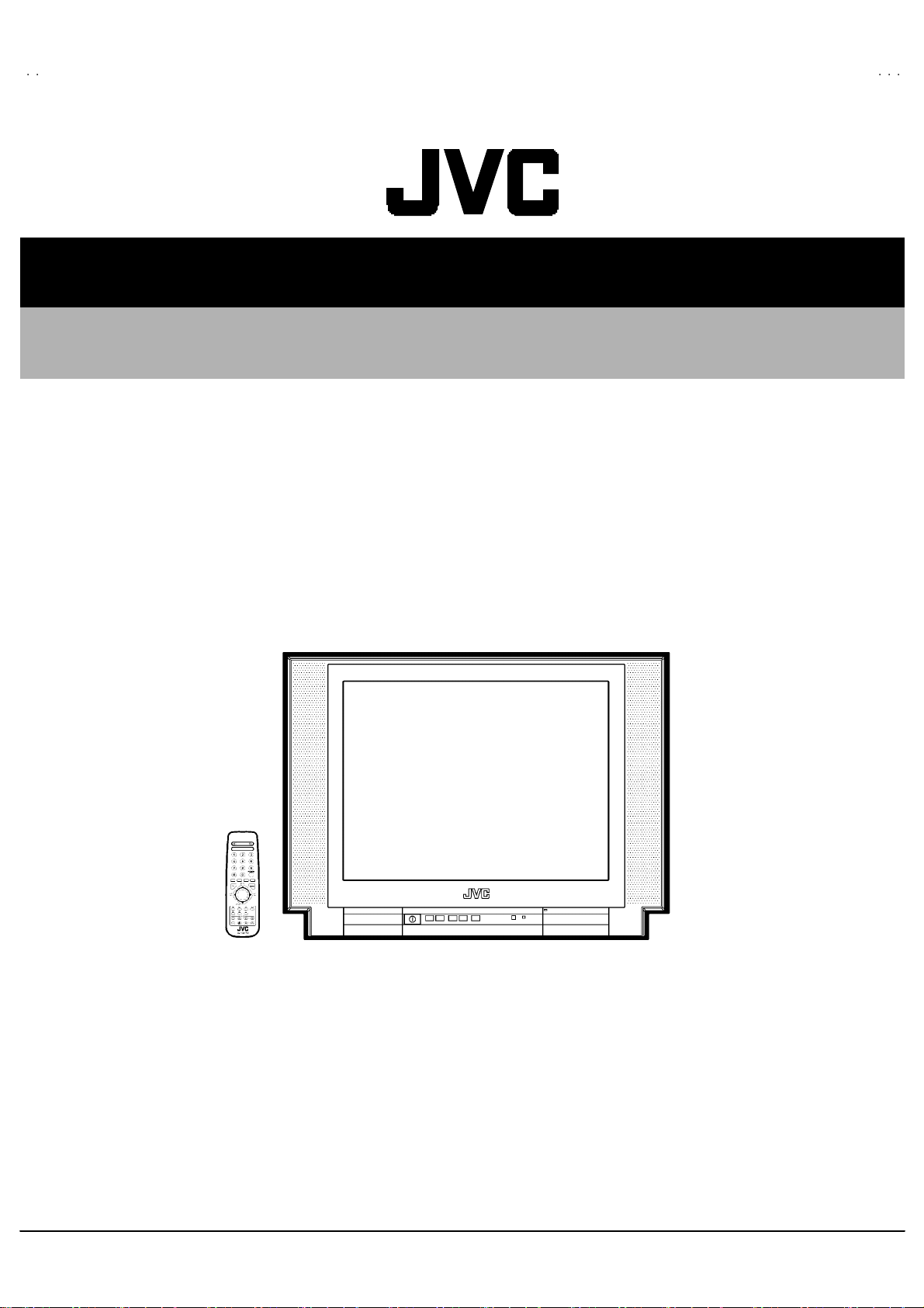
COLOUR TELEVISION
AV-21BF11ENS
AV-21BF11EES
AV-21BF11ENS
AV-21BF11EE
AV-21BF11EP
AV-21BF11EJ
AV-21BF11EPS
AV-21BF11EJS
CONTENTS
!
SPECIFICATIONS
! SAFETY PRECAUT IONS ・・・・・・・・・・・・・・
!
FEATURES
!
MAIN DIFFERENCE LIST ・・・・・・・・・・・・・・
1
・・・・・・・・・・・・・・・・・・・・・・・・・・
・・・・・・・・・・・・・・・・・・・・・・・・・・
・・・・・・・・・・・・・・・・・・・・・・・・・・・・・・・・・・・・・・・・・・・・・・・・・・・・
・・・・・・・・・・・・・・・・・・・・
・・・・・・・・・・・・・・・・・・・・
・・・・・・・・・・・・・・・・・・・・・・・・・・・・・・・・・・・・・・・・
・・・・・・・・・・・・・・4
・・・・・・・・・・・・・・・・・・・・・・・・・・・・
・・・・・・・・・・・・・・5
・・・・・・・・・・・・・・・・・・・・・・・・・・・・
COPYRIGHT © 2002 VICTOR COMPANY OF JAPAN, LTD.
2
5
!
SPECIFIC SERVICE INSTRUCTIONS
! SERVICE ADJUSTMENTS・・・・・・・・・・・・
!
PARTS LIST
★
OPERATING INSTRUCTIONS
★
STAND ARD CIRCUIT DIAGRAM
・・・・・・・・・・・・・・・・・・・・・・・
・・・・・・・・・・・・・・・・・・・・・・・
・・・・・・・・・・・・・・・・・・・・・・・・・・・・・・・・・・・・・・・・・・・・・・
・・・・・・・・・・・・ 11
・・・・・・・・・・・・・・・・・・・・・・・・
・・・・
・・・・
・・・・・・・・
・・・・・・・
・・・・・・・
・・・・・・・・・・・・・・
No.520 55
Jul. 200 2
6
21
2- 1
Page 2
A
V-21BF11ENS
A
A
A
V-21BF11EES
V-21BF11EPS
V-21BF11EJS
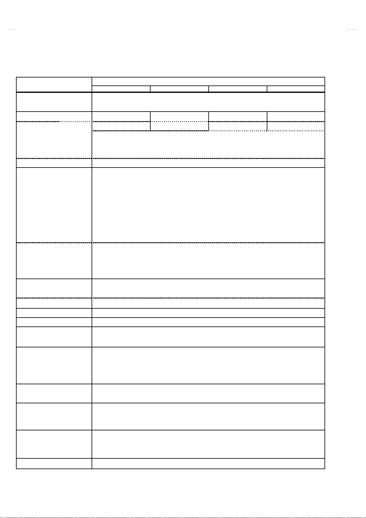
SPECIFICATIONS
Item
Dimensions ( W××××H××××D ) 60 0m m× 4 48mm×4 76mm
Mass 22 .2 kg
TV RF System B/G B/G , D/K , K1 B/G , L/L ’ I/I ’
TV Mode PAL PAL / SEC AM PA L / SE C AM PA LColour Syst em
Video Mode PA L / SE C AM / N TSC 3 .58 / NTSC 4 .43 (EES/E PS M ODEL)
Sound System German + NICAM
Teletext System Fast ext / Topte xt
Receiving Frequency
VHF (VL) 46.25 MHz ~ 1 68. 25MHz
(VH) 17 5.25MH z ~ 46 3.2 5MHz
UHF 47 1.2 5MHz ~ 86 3.2 5MHz
CATV S01 - S4 1 & S75-S79
Intermediate Fr equency
VIF Carrier 38 .9 MHz ( B/G , D /K , L , I ) / 3 3.9MHz( L’)
SIF C ar rier 33.4 MHz (5 .5MHz:B/G) / 32. 9MHz (6.0MHz:D/K , I ) / 32.4MHz ( 6. 5MHz: L) / 40.4MHz (6.5MHz:L’)
Colour Sub Carrier Freq.
PAL 4.43MHz
SE CAM 4.43MHz
NT S C 3.58MHz / 4.43MHz
Power Input AC 2 20V ~240V , 50Hz
Power Consumption 85W (Max) ,2 .5W(Standby)
Aerial Input Term 75 Ωun ba lanc ed, C oax ial
Pictur e Tube Size Visi bl e size : 51cm, M eas ured dia gon ally
Hi gh Vo l t ag e 27 .7 kV
Speake r 5.7 cm×16cm Oval type ×2
Au dio Output 6.5 W×2
Input
Output
Input Terminal
Remote Control Unit VE -3 00 17763 (R M-C 1100), (A A/R0 6 dry b atter y×2)
Vide o 1Vp- p, 75
S/V ideo Y : 1Vp- p Pos it i ve
Au di o ( L/ R) 500mVr ms, Hi gh Imped an ce
Vide o 1Vp- p 7 5Ω
Au di o ( L/ R) 500mVr ms, Low Impe da nce
Rear Sid e AV 1 (Vi d eo/Aud i o/R GB)
Front Side AV 3 ( Vi d eo/Aud i o)
Front Side H eadph on e jac k (S ter e o mi ni jack 3.5 φ)Output Terminal
Rear Sid e AV 1 (Vi d eo/Aud i o)
AV-21BF11ENS AV-21BF11EES AV-21BF11EPS AV-21BF11EJS
PAL / NTSC 3 .58 / NTSC 4 .43 (ENS/ EJS MODEL)
Ω
C : 0 .2 86Vp-p
AV 2 (Vid eo/A udio/S-VHS)
AV 2 (Vi d eo/A ud io) (S el ect ed T V,A V1 or AV3)
Content
De sign & speci f icatio ns ar e su bje ct to cha ng e wi thout no t ice.
2
No.52055
Page 3
A
A
S
A
S
A
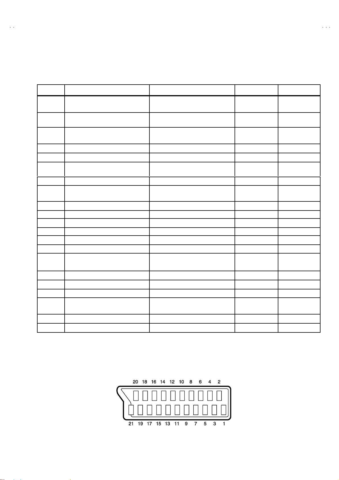
■■■■21-pin Euro connector (SCART socket) : AV-1 / AV-2
(P-P= Peak to Peak, S-W= Sync tip to white peak, B-W= Blanking to white peak)
V-21BF11ENS
V-21BF11EE
V-21BF11EP
V-21BF11EJS
Pin No.
1
2
3
4
5 GND (B) ○○
6
7
8
9 GND (G) ○○
10 SCL3 NC NC
11
12 SDA3 NC NC
13
14
15
16 Ys input Low : 0 - 0.4, High : 1 - 3V, 75Ω○ NC
17
18
19
20
21
AUDIO R o utput 50 0m Vr ms(Nomina l) ,
AUDIO R i n put 50 0m Vr ms(Nomina l) ,
AUDIO L outp ut 50 0m Vr ms(Nomina l),
AUDIO G ND ○○
AUDIO L input 500mVrms(Nominal),
B in pu t
FUNCTION SW
(SLOW SW)
G in put
GND (R)
GND (YS) ○○
R / C input
GND(V IDEO output)
GND(V IDEO input) ○○
VIDEO ou tpu t
VIDEO / Y input
COM MON G ND ○○
Signal Designation Matching Value AV-1
○
Low impedance
High i m pe danc e
Low impedance
High i m pe danc e
70 0m V
Low : 0-3V, High : 8-12V, High
impedance
70 0m V
R : 700mV
C : 300mV
1V
P- P
1V
P- P
Ω○NC
, 75
B- W
, 75Ω○
B- W
Ω
, 75
B- W
, 75Ω
P- P
(Nega ti ve g oi n g s ync ), 75
(Nega ti ve g oi n g s ync ), 75
Ω○
Ω○ ○
(TV OUT)
○○
○
(TV OUT)
○○
○○
○○
○
(only R )
○○
(TV)
AV - 2222
○
○
NC
○
○
[Pin assignment]
No.52055
3
Page 4
A
V-21BF11ENS
A
A
A
V-21BF11EES
V-21BF11EPS
V-21BF11EJS
SAFETY PRECAUTIONS
1. T he des i gn of th is pr od uc t c on ta in s sp ecial hard ware , ma ny
circuit s and components specially for saf ety purposes. For
con tinu ed pr ot ecti on , n o chan g es sh ould b e ma de to the o rig i nal
d esign un less a uth or ized in writi n g by th e manu fac t urer .
Replacem ent p arts m ust b e i d entic al to thos e u sed in th e or i gi n al
ci rcu its. Se r v ic e s h ou ld be pe rf or me d b y qua lifi e d per s o nn el
on ly.
2. Al te rati on s of the desig n or cir cuitry of t he prod uc ts sh ould not be
made. Any design alterations or additions will void the
manu fac t urer 's warra nt y and will f urth er r el i eve t he ma nufac tu rer
of r esp onsib ili ty for per s o na l injury or pr operty d am ag e res ul t ing
th erefr om.
3. M an y el ectr i cal an d mech anic a l p ar ts i n th e pr od uc ts ha v e
special safety-related chara cteristics. T hese characteristics are
oft en no t e vi den t f r om v i sua l insp ecti on nor ca n t he pro tect io n
aff orde d by th em nece ssarily be ob tain ed b y u s in g r ep l ac em en t
com po nents rated for hig he r vo l tag e, watt age, etc . R ep lac em en t
p arts whic h have th ese sp ecial s afet y ch ar act erist ics ar e
ide ntified in the parts list of Ser vic e manua l. El ectric al
components having such features are ide ntified by shading
on the sche mat ic s and b y (!!!! ) on the parts list in Service
manual. The us e of a sub sti tu te r ep lac em en t which do es n ot
h ave th e sam e s af ety c h ar ac t erist ics as t he reco mmen ded
replac ement par t sh ow n i n th e parts list of Ser v i ce man ual m ay
cause shock, fire, or other hazards.
4. Don't s hor t between the LIVE side ground and ISOLATED
(NE UTRAL) s ide ground or EARTH side ground when
repairing.
Some model's power circuit is partly different in the GND. T he
diff erenc e of th e GND is sh ow n by t he LIVE : (") side GN D, the
ISO LATE D(N EU TR AL) : ( #) side GN D an d EA RTH : ($) side
GND. Don't short between the LIVE side GND and
ISO LATE D(N EU TR AL) si de GND or EAR TH sid e GN D an d
n ever mea sure w it h a mea sur i ng a ppa r atus ( osci l lo scop e etc.)
th e LI VE sid e GN D an d IS OL ATED(NEUTR AL ) s id e GN D or
EARTH sid e GND at the s ame time.
If above not e will not be kept, a fuse or any parts will be broken.
5. If any repair has been made to the chassis, it is recommended
th at t he B1 set ting shou l d b e c h ec ked or adju ste d ( Se e
ADJUSTM ENT OF B 1 POW E R SUPPLY).
6. The high vol ta ge app lie d t o th e pi ctu r e tu be mu s t c on form wit h
th at sp ecifi ed i n S ervi ce man ual . E xc essi ve h i gh volt ag e c a n
cau se an i ncr e ase i n X- R ay em iss i on , arci ng an d possi b le
component damage, therefore operation under excessive high
voltage conditions should be kept to a minimum, or should be
preve nt ed. If s ever e arc ing occur s, r emov e t he AC power
immed iate l y and de ter m i ne th e ca us e b y vi sua l insp ec t ion
(incor r ec t in stal lat i on, cr ac ke d or melte d hi gh v o lt age harn ess,
p oor so ld er ing, et c.) . T o m ai nt ain the prope r mi n imu m le vel of
sof t X- R ay em iss i on, c omp on en ts i n th e hi gh voltag e c i r cuitr y
incl ud i ng t he pict ure tu be must b e t he e xact r ep l acem e nts or
alte rn at ives ap pr ove d b y th e manuf ac t urer of th e c omplet e
prod uct.
7. Do n ot c hec k high volt ag e by dr aw ing an arc. Use a hi gh volt age
meter or a hig h v oltag e pr ob e wit h a VT V M. Dis charg e the
picture tube before attempting meter connection, by connecting
a cl i p le ad to th e gr ou nd f rame a nd c onn ecti n g th e oth er end of
the lead through a 10kΩ 2W resi s to r to the an ode b utt on .
8. When service is r equ ire d, ob serve the or igina l lea d dr ess. E x tr a
prec aut i on sh ou ld b e given t o assur e cor r ect l ea d dress in th e
high vol tag e circui t a rea. W her e a s hor t c i r cuit h as occ u rr e d,
th ose co mpon ent s tha t indica te evide nce of ove r hea ting should
b e r e place d. A lways u s e th e manuf act ur er 's rep lacem ent
components.
9. Isolation Check
(Safety for Electrical Shock Hazard)
Af ter r e- ass embl in g th e p r odu ct, always per f orm an i solat io n
ch eck on the expo s ed me tal p ar ts of t he cabin et ( a nte nn a
ter m i na ls, vid eo /au dio i npu t and outpu t t ermi n al s, C on trol kn obs,
metal cabinet, screwheads, earphone jack, control shafts, etc.)
to be su re th e p r odu ct is s af e t o o pe rate with ou t d an ger of
elect rical shoc k.
(1) Dielectric Strength Test
The iso lation be tw een the AC pr im a ry ci rcu it an d al l me tal p arts
exp osed t o the us er, p ar ticular ly an y e xpos ed met al p art having a
retu rn p ath to t he c hass is sho uld withs tan d a vol t age of 3000 V
AC (r.m. s.) for a period of one second.
(. . . . W it hstan d a v o lt age of 110 0V A C (r .m. s.) t o an ap pli anc e
rate d up to 12 0V , an d 3 00 0V AC ( r.m. s.) to an ap pl i an c e r at ed
200V or more, for a period of one second.)
This meth od of test r equi res a test equipment n ot g enerall y fou nd
in t he serv ic e trad e.
(2) Leakage Current Check
Plug th e AC l in e c ord d irect ly into the A C ou tlet ( d o not use a lin e
isol ati o n transf orm er du r ing this ch eck.). U sin g a " Lea kag e
Current T este r", me as ur e th e l ea k ag e cu rr e nt f rom eac h ex p os ed
metal p ar t of the cabine t, p art icu lar ly any e x pos ed me tal p art
h aving a re turn pa th to the ch assis , to a kn own go od ea rt h
grou nd (w a ter pip e, e tc.). An y l eaka ge c ur r en t must n ot e xceed
0.5mA AC (r.m.s.).
Howev e r, in trop ic al ar ea , th is mu st no t ex ce ed 0.2 mA AC
(r.m.s.).
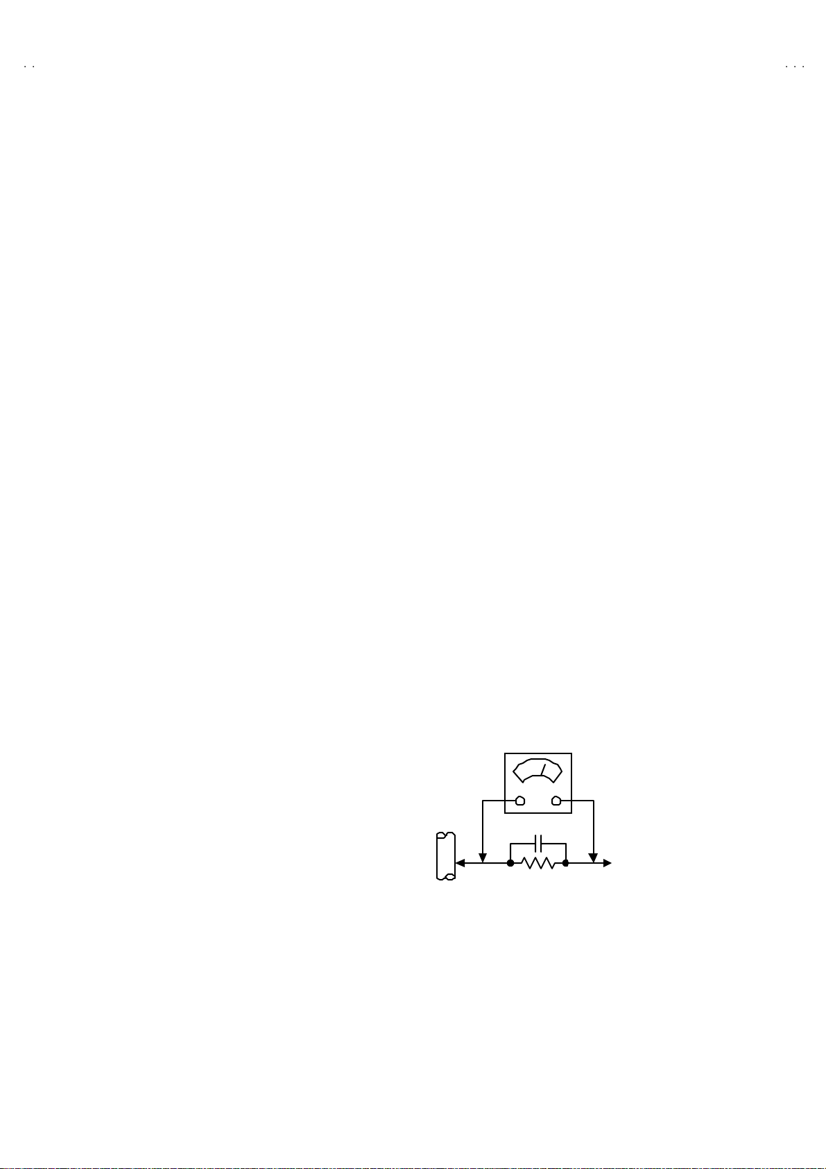
"""" Alte rn at e Che ck M et hod
Plug th e AC l in e c ord d irect ly into the A C ou tlet ( d o not use a lin e
isol ati o n tran sfor m er dur i ng this c he c k.). Use an AC vo lt meter
h aving 1 00 0 oh ms pe r vol t or mor e s ens it i vity i n th e fo llowi ng
mann er . C on nec t a 1 50 0Ω 10W res ist or para lle led b y a 0 .1 5µF
AC-type c apa cit or bet ween an expo sed met al pa rt and a kno wn
g ood e ar th gr o und (water pi pe , etc.) . M eas ur e th e A C volt ag e
acr os s th e res ist or wi th th e AC vo l tm eter. Move th e r es i stor
con nec tion to e ach exp ose d me tal part, p art i cularly any exp osed
metal p ar t havi n g a r etu rn pat h to the ch assis, and m easu r e th e
AC vol tag e ac ros s the res ist or. No w , re v er se th e pl u g in th e AC
ou tl et and re pe at eac h mea suremen t. An y vol t ag e me asu re d
must no t e xc eed 0 .7 5V AC (r.m. s.) . This c orre spo nds to 0 .5mA
AC (r.m. s.).
Howeve r, in tropica l area, this must n ot exce ed 0 .3V AC ( r .m.s.).
This corresponds to 0.2mA AC (r.m.s.).
AC VOLT MET ER
(HAVING 1000 Ω /V,
OR MOR E SENSIT IVITY)
0.15μF AC-T YPE
PLACE THIS PROBE
1500 Ω 10W
GOOD EARTH GROUND
ON E A C H EX PO SE D
ME T AL PA RT
4
No.52055
Page 5
A
A
S
A
S
A
FEATURES
V-21BF11ENS
V-21BF11EE
V-21BF11EP
V-21BF11EJS
1. It is a remote controlled color television.
2. 10 0 pr og r am s fr om VHF , UH F b an ds or cab l e ch ann el s can be
pres et.
3. It c an tun e c abl e c ha nn els.
4. Cont ro l lin g th e TV i s ver y easy by its men u driven s yst em .
5. It h as two Eu r oc on n ector s ockets for exte rnal de vice (suc h as
vi de o reco rder , vid eo games , a udi o set, etc.)
6. Front AV In put ava ilable.
7. St ereo s ound s ys tems ( Ger m an + N ic am) ar e a v ailab l e.
8. Full functio n Teletext (Fast ext, Topte xt).
9. It is possib l e to con nec t h ead ph one.
10. Direct channel access.
11 . APS (Aut omat ic P r ogr am m i ng Syste m).
12 . All pr og r ams ca n b e nam ed .
13 . Forward o r bac kward au to ma ti c tu ning .
14 . Sl ee p timer.
15. Child Lock
16 . Au tom at ic sou nd mu te when no tran smiss i on .
17 . 5 minu tes aft er the br o adc asti ng ( c l osed own) , the TV s witc h es
itsel f aut omati ca lly t o st and- by mod e.
MAIN DIFFERENCE LIST
Model Name
!!!!
Part Na me
MAIN PWB VE-20101119 VE-20101113 VE-20101120 VE-20101540
!
RATING LABEL VE-20101395
CARTON BOX VE-50028254 VE-50028331 VE-50028286 VE-50028413
AV-2 1BF11ENS AV -21B F11EES AV-2 1BF11EP S AV-2 1BF11EJ S
VE-20101660
VE-20101560
(POLAND)
VE-20101548 VE-20101872
!
INSTRUCTION BOOK VE-50028252 VE-50028323 VE- 50028287 VE-50028290
No.52055
5
Page 6

A
V-21BF11ENS
A
A
A
V-21BF11EES
V-21BF11EPS
V-21BF11EJS
SPECIFIC SERVICE INSTRUCTIONS
DISASSEMBLY PROCEDURE
REMOVING THE REAR COVER
1. Unp lu g t he po we r c ord.
2. Remove th e 6 screws marked A as show n in t he F i g. 1.
3. W i thdr a w t he r ear co ver to wa rd y ou .
REMOVING THE MAIN PWB
" Removing the rear cover.
1. Rem ove the sc r ew m ar ked B as s hown in the Fig.1.
2. Sl i ght ly r ai s e t he bo th sid es of th e ch assi s b y h and an d withd r aw
th e M AIN PW B backw ar d.
(If necessary, take off the wire clamp, co nnectors etc.)
REMOVING THE SPEAKER
"
Removing the rear cover.
1. Rem ove t he 2 scr ews m ar k ed C, an d re mo v e sp ea k er as s how n
in Fig. 1.
2. Rem ove the sp eake r .
REMOVING THE FRONT AV & HEADPHONE PWB
" Removing the rear cover.
"
Removing th e rear MAIN PW B .
1. Remove the 2 scr ew s marked D.
2. Rem ove the FR ONT AV & HE AD PHONE PW B.
CHECKIN G THE PW BOARD
To c h ec k the back s i de of th e PW B oard.
1) Pu ll o ut th e PW B oar d. (Ref er to REMOV ING THE MA IN
PWB ) .
2) Erec t th e PW B oar d ve rtic al l y so t ha t y ou c an eas i ly c h ec k
th e back s i de of th e PW B oard.
[CAUTION]
" When e recting the PW Board, be c areful so that t here will be no
con tact ing with ot her PW Boar d.
" Be fore tur n ing on po wer , ma ke sur e t ha t the wire co nn ecto r is
prop er l y con nected .
" W hen condu cti ng a c h ec k wi th p ow er su pplied , b e sure to c onfir m
th at t he CRT E AR T H WI RE (B RAIDED AS S’Y) is co nne c ted t o
th e C R T SOC KE T PW b oard.
WIRE CLAMPIN G AND CABLE T Y ING
1. Be sure t o clamp th e wire.
2. Never rem o ve th e cable ti e u sed f or t ying th e wires to ge the r.
Sh oul d it be i n adv e rt ent l y rem ove d, b e su r e to tie th e wires w it h
a n ew c able tie.
6
No.52055
Page 7

A
V-21BF11ENS
A
S
A
S
A
V-21BF11EE
V-21BF11EP
V-21BF11EJS
(×6)
A
REAR COVER
(×1)
B
MAIN PWB
FRONT AV & HEADPHONE PWB
FRONT CABINET
(×1)
CRT
C
(×2)
SP EAKER
D
Fig. 1
No.52055
7
Page 8

A
V-21BF11ENS
A
A
A
V-21BF11EES
V-21BF11EPS
V-21BF11EJS
REPLACEMENT OF CHIP COMPONENT
! CAUTIONS
1. Avoid heating for more than 3 seconds.
2. Do n ot ru b t he el ect ro des an d t he r esist p arts of the p att er n.
3. W hen rem oving a c hi p par t, m el t th e s older ad equate ly.
4. Do n ot r euse a ch ip p ar t afte r re mo v ing it .
! SOLDERING IRON
1. Use a hig h i ns ulatio n s older i ng iron with a t hin poin ted end of it.
2. A 3 0w s older ing i r on is r ecommend ed for easil y r em oving p ar ts.
!
REPLACEMENT STEPS
1. How to remove Chip parts
####
Resi st o rs, capacitors , etc
(1) As sh own in the f ig ur e, pu sh th e pa rt w ith tw ee zer s and
alte rn at ely melt the s ol de r at eac h end.
(2) Sh if t with tweeze rs and r em ove th e c h i p p art.
#### T rans isto rs, d io d es , va ria bl e r esist or s, etc
(1) Ap pl y e xt ra so ld er to eac h le ad .
SOLDE R SOLDE R
2. How to install Chip parts
####
Resi st o rs, ca pacit ors , etc
(1) Apply solder to th e patt ern a s i ndicated in the fi g ure.
(2) Gr asp t he ch ip p art with tw ee z er s and pl ac e it on th e s old er.
The n hea t and me lt th e so lder a t both ends of t he chi p part.
#### T rans isto rs, d io d es , va ria bl e r esist or s, etc
(1) Apply solder to th e patt ern a s i ndicated in the fi g ure.
(2) Grasp the ch ip p art wit h t weeze rs and p lace it on the s o l der .
(3) First s older lead A as indica ted in t he figure .
A
(2) As sh own in the f ig ur e, pu sh th e pa rt w ith tw ee zer s and
alte rn at ely melt th e sol d er at each le ad . S hi ft an d r em ove the
chip part.
(4) The n solder le ads B and C .
Note : A fte r re moving t he part, r emove rem ain ing solder fr o m the
pattern.
8
No.52055
C
A
C
B
B
Page 9

A
A
S
A
S
A
MEMORY IC REPLACEMENT
VALUE
VALUE
ITEM
MENU
MU T I NG
INFORMATION
COLOUR k
STANDARD
1. Memory IC
This model use a memory IC.
Thi s me mo r y I C st or es d ata for pr op er op er ati o n of the vid eo
an d d ef lecti on c ircu it s.
When replacing, be s ure to use an IC containing this (initial
valu e) data.
2. Memory IC replacement procedure
(1) Power off
Switch of f t he p ow er an d dis con nec t th e power co rd from
the wall outlet.
(2) Replace the memory IC
Init ial value m ust be entered into the n ew IC .
(3) Power on
Connect th e pow er c or d t o the wa ll o utlet an d s witc h on t he
power.
V-21BF11ENS
V-21BF11EE
V-21BF11EP
V-21BF11EJS
SE RVICE MENU
Fig.1
SERVICE MENU SELECT KEY
(4) SERVICE MENU setting
1) Pr ess MENU key an d, while th e di spla yed M ENU
screen, press 4, 7, 2, 5 key on th e rem ote co ntrol uni t or
press MUTING key and INFORMATION key at the
same time.
2) The SER V ICE M ENU sc r ee n of F i g.1 is d isp l ay ed .
3) Ve rif y what to s et i n th e SERV ICE M EN U, and set
what ever is nec e s sary (Fig.1 ). Ref er to th e SE RVICE
ADJU STM ENT for settin g.
4) Press the STANDARD key to exit SERVICE MENU.
(5) Rec eiv e channel setting
Refe r to the OPERATIN G I N STRUCTIO NS ( USER ’S
GUID E) a nd set th e rece ive ch an nel s (Chan n els Pr eset ) as
described.
(6) User se tt ing s
Check th e us er s ett ing it ems ac c ordi ng to aft er pa ge .
Wher e th ese d o not a gr ee, r efer to t he OPE RAT ING
INSTRUCTIONS (USER’ S GUIDE) and set th e items as
described.
ITEM
SELECT(▲)
SELECT(-)
FUNCTION
POWER
NUMBER
key
ey
SELECT(+)
SELECT(▼)
Fig.2
No. 52055
9
Page 10

A
V-21BF11ENS
A
A
A
V-21BF11EES
V-21BF11EPS
V-21BF11EJS
SETTING OF THE LAST MEMORY FOR SHIPMENT
■■■■ USER SETTING VALUES
Setting Item Setting Value Setting Item Setting Value
SOUND MENU FEATURE MENU
BA LANCE CEN TER SLEEP TIMER OFF
BA SS
↑
CHILD LO CK OFF
TR EBL E
MODE STEREO AV-2 OUTPUT TV
EFFECT OFF
PICTURE MENU INSTALL
BRIGHTNESS PROGRAMME
CONTRAST BAND
COLOUR CHANNEL
SHAR PNES S SE ARCH
HUE (only NTSC)
PICTURE MODE AUTO STO RE
Thes e ad j us t a re aut om ati ca lly
restore d when AP S b it in Se rvice
menu i s set .
The proc edure f or s e tti ng AP S
bit is describe d bellow.
↑
LANG UAGE ENGL ISH
Refe r to t he INSTRUCTION
BOO K
FINE TUNING
■ SETTING APS BIT IN SERVICE MENU
1) En ter s er vic e me nu in TV m ode by press i ng “ INFORMATION ” a nd “MUTI NG” keys simultan eou sly . S ervic e M en u will ap pea r.
2) Se lect TX1 (TEL ET EXT OPTIO N) b y pressin g U p /Dow n keys o n r em ot e c ontro l un it.
3) Press the 7 key on remot e control unit to set APS bit . (After this, bit 7 of TX1 will be “1”)
4) Press STANDARD key on remote cont rol unit to exit service mode.
NOTE : DO NOT TURN OFF THE TV BY USING POWER BUTTON O N THE FRONT PANEL.
10
No. 52055
Page 11

A
A
S
A
S
A
SERVICE ADJUSTMENTS
ADJUSTMENT PREPARATION
1. You ca n ma ke t he ne ce ssa ry ad ju st me nts for t h is un it wit h
either the Remote Control Unit or with the adjustment tools
and parts as given below.
2. Adjustment with the Remote Control Unit i s made on the
basis of the initial setting va lues, however, the new setting
values which set the screen to its opti mum condition may
differ f rom the init ia l s ettings.
3. M ak e s ur e t hat AC p ow er i s tu r ned on c orrec tly.
4. T ur n on the power for set an d test eq uip me nt bef or e use , and
start t he ad justmen t p roced ur es aft er w ai ti ng at least 30 minut es.
5. U nl ess o the r wise s pec if i ed, prep are t he most s u it able recep tion
or inp ut sign al for adjust ment.
6. N ever t ouch a ny a dj ust me nt p art s whi c h ar e n ot spec ified in th e
list for this adjustment - variable resistors, transformers,
condensers, etc.
7. Pr esetti ng before ad j ustm en t.
Unl es s ot her w i se spec if i ed i n t he adjustme nt i nstr uct i ons , p r ese t
th e f ollo w ing f uncti ons with th e re mo te c ont ro l un it :
BRIGHT NES S
CONTRAST
COLOUR
SHAR PNES S
V-21BF11ENS
V-21BF11EE
V-21BF11EP
V-21BF11EJS
CENTER
ADJUSTMENT EQUIPMENT
1. DC voltmeter (or digital voltmet er)
2. Si gn al g en erat or (P attern g en erat or) [PAL/SECAM/NTSC]
3. Remote control unit
MAIN PARTS LOCATIONS
FRONT
ADJUSTMENT ITEM
!
SCR EEN A DJ UST MENT
! OSD HORIZONTAL POSITION ADJUSTME NT
!
IF AD JU STM EN T
! AGC A UTO MATI CALLY A DJUSTM EN T
! DEFLECTION CIRCUIT ADJUSTMENT
!
GEO MET R Y MENU ADJ UST MENT
! WHITE BALANCE ADJUSTMENT
FRONT
FRONT AV &
HEADPHONE PWB
TOP
CRT SOCKET PWB
No. 52055
MAIN PWB
11
Page 12

A
V-21BF11ENS
A
A
A
V-21BF11EES
V-21BF11EPS
V-21BF11EJS
BASIC OPERATION SERVICE MENU
■■■■ HOW TO ENTER THE SERVICE MENU
1) Pr ess the MENU key.
2) ME NU s c reen of fig.1 will b e d ispla ye d
MENU SCRE EN
MENU
SOUND
PICTURE
FEATURE
INSTALL
PROGRAM
REMOTE CONTROL UNI T key NAME
NUMBER key
Fig.1
3) W hile the ME NU sc r ee n is disp lay ed , p r es s th e 4,7 ,2, 5 ke y or
INFORMATION key and MUTING key simultaneously.
4) The SERV ICE MENU screen of (Fig.2) will be displayed.
SE RVICE MENU
ADJUSTMENT ITEM SETTING VALUE
Fig.2
■ SELECTION OF ADJUSTMENT ITEMS
1) En ter th e SERVICE MENU
2) Press the FUNCTION / key and select the ADJUSTMENT
ITEM.
3) Press the F UNCTION / key and s et t he SETTI NG VAL UE.
■ HOW TO EXIT SERVICE MODE
1) Pr ess the STANDARD Key on REMOTE CO NTROL UNIT.
■ HOW TO ENTER THE GEOMETRY MENU
"
Thi s mo del is buil t- i n GEO ME T RY M EN U f or ge om et ry
adjustment.
1) En ter th e SERVICE MENU
2) Press the GREEN key, geometry menu appears (Fig. 3).
3) Press the FUNCTION / key and select the ADJUSTMENT
ITEM.
4) Press the F UNCTION / key and s et t he SETTI NG VAL UE.
GEOME TRY MEN U
INFORMATION
key
AV key
" FUNC TI ON OF COL O UR k ey
RED key :
It switch es th e AV L to ON o r OF F mode on servic e
menu . AV L wo rd i s visible o n s er vice m en u when
AV L is o n.
GREE N k ey :
It s witch es t o GE OM ETR Y adjust menu. G eomet ry
of th e p ict ure i s a dj ust ed in th is m enu.
YELLOW key :
It s witch es t o VE RT ICAL SC AN DISA BLE mode.
It i s us eful t o adj ust scr een volt age.
BL UE ke y :
It i s used to adj ust AGC an d I F au tom a tical l y on
ser v ice me nu.
STANDARD
key
COLOUR key
MENU key
FUNCTION
key
GEOME TRY
VSIZ 023
VPOS 028
VSCO 000
VCCO 008
HSIZ 007
HPOS 039
HPIN 015
ADJUSTMENT ITEM SETTING VALUE
Fig.3
12
No. 52055
Page 13

A
A
S
A
S
A
■
ADJUSTMENT ITEM & INITIAL (Recommended) SETTING VALUE in the SERVICE MENU
ADJUSTMENT
ITEM
OSD HOR IZONTAL POSI TION OF OSD 082
IF1 IF C OAR S E AD JUST MENT 004
IF2 IF FINE ADJUSTME NT 065
IF3 IF C OAR S E AD JUST MENT FOR L-P RI ME 004
IF4 IF FINE ADJUSTMENT FOR L-PRIM E 065
AGC AUTOMATIC GA IN CONT ROL Autom at ic ally
VLIN VERTICA L LINEARITY 045
RGBH RGB MODE HORIZONTAL SHIFT OFFSET 007
VSOF VE RTICA L S IZE OF FSE T for 60Hz -01
VP OF VE RTICA L PO SITIO N OFFSET f or 60 Hz -01
HSOF HORIZONTAL SIZE OFFS ET for 60Hz Not used
HPOF H ORIZONTAL POSI TION OFFSE T for 6 0Hz +00
HTOF HORIZONTAL TRAPEZOID OFFSET for 60Hz Not used
WR WHITE POINT AD JUST ME NT FOR RE D 04 0
WG W H IT E PO INT ADJUST ME NT FOR GREEN 04 0
WB W H ITE PO INT ADJUSTME NT FOR BLUE 040
BR BIA S FOR RED 030
BG BIA S FOR G REEN 031
APR AUTOMATIC RGB P EAK REGUL ATION THRESHOL D 010
BRI BRIGHT NES S 030
CON CONT RAST 035
COL COLOUR 038
SHR SHARP 006
HUE HUE 031
VOL VOLU ME 01 5
WR-R WHITE PO INT ADJU STMENT for RED (R GBm o de) 030
WG-R W H IT E PO INT ADJUST ME NT for GR EE N (RGBm o de) 055
WB-R W H ITE PO INT ADJU STMENT for BL UE (RGBmo de) 032
FMP 1 FM PRES CA LER W HE N AV L IS OF F 009
NIP1 NICAM PRESCALER WHEN AVL IS OFF 020
SCP1 SCAR T PRES CA LER W HE N AV L IS OFF 01 3
SE C1 SE CAM PRE SCALE R WH E N AV L IS OFF 013
FMP 2 FM PRES CA LER W HE N AV L IS ON 013
NIP2 NICAM PRESCALER WHEN AVL IS ON 016
SCP2 SCAR T PRES CA LER W HE N AV L IS ON 01 3
SE C2 SE CAM PRE SCALE R WH E N AV L IS ON 013
F1H HIGH BYTE OF VHF1-VHF3 CROSS-OVER FREQUENCY 00001001
F1L LOW BYTE O F VHF1- VHF3 C ROSS -O VER FREQ UE NCY 10010010
F2H HIGH BYTE OF VHF3-UHF CROSS-OVER FREQUENCY 00011011
F2L LOW BYTE O F VHF3- UHF CR OS S-OVER FR EQ UE NCY 10 00 00 10
BS 1 BA ND SW ITCHIN G B YT E F OR V HF1 0000 0011
BS 2 BA ND SW ITCHIN G B YT E F OR V HF3 0000 0110
BS 3 BA ND SW ITCHIN G B YT E F OR U H F 10 00 01 01
CB C ON T R OL B YTE 10 00 11 10
DESCRIPTION INITIAL VALUE
V-21BF11ENS
V-21BF11EE
V-21BF11EP
V-21BF11EJS
1/2
No. 52055
13
Page 14

A
V-21BF11ENS
A
A
A
V-21BF11EES
V-21BF11EPS
V-21BF11EJS
■
ADJUSTMENT ITEM & INITIAL (Recommended) SETTING VALUE in the SERVICE MENU
2/2
ADJUSTMENT
ITEM
OP1 PERIPHERAL OPTIONS 01110101
OP2 RECEPT I ON STAN DARD OPT IO NS 00001001 (EN)
OP3 VIDEO OPTI ONS 01 101101 (EN)
OP4 TV F E ATURES 10 00 10 00
OP5 CHA N NE L T A BLES 00 0000 00
TX1 TEL ETEXT O PTIONS 10 01 01 01 (E N)
GEOM GEO MET R Y OPTIO NS 0000 0000
OP8 PIP PR ES ET CHANGE 00000000
[GE OMETRY MENU ]
ADJUSTMENT
ITEM
VSIZ VERTICA L S IZE f or 50Hz 030
VP OS VERTICA L POSITIO N for 50Hz 010
CSCO VERTICAL S-CORRECTION for 50Hz Not used
VCCO VERTICAL CORNER CORRECT ION for 50Hz Not used
HSIZ HORIZONTAL SIZE f or 50Hz Not used
HPOS H ORIZONTAL P OSI TION for 50Hz 035
HPIN HORIZONTAL P INCUSHION for 50Hz Not used
HCCO HORIZONTAL CORNER CORRECTION for 50Hz Not used
HTRP HORIZONTAL TRAPEZOID for 50Hz Not used
VZSZ VERTICA L ZOOM S IZE f or 50 Hz Not used
DESC RIPTI ON INITIAL VALU E
01 00 10 01 (EP)
00 01 10 01 (EE)
00 10 00 01 (EJ)
11 10 11 01 (EP/EE /EJ)
10 00 01 01 (EP)
10 00 11 01 (EE)
10 01 11 01 (EJ)
DESCRIPTION INITIAL VALUE
14
No. 52055
Page 15

A
A
S
A
S
A
ADJUSTMENTS
■■■■ SCREEN ADJUSTM ENT
Item
SCREEN
adjust me nt
■ OSD HORIZONTAL POSITION ADJUSTMENT
Item
HORI ZONTAL
POSITION O F
OSD
adjust me nt
Measuring
instrume nt
Remote
control unit
Measuring
instrume nt
Remote
control unit
Test point Ad justment part Description
SCREEN VR
[On the FBT]
Test point Ad justment part Description
OSD 1. En ter SE R VIC E MENU.
SE RVICE MENU SCREEN
V-21BF11ENS
V-21BF11EE
V-21BF11EP
V-21BF11EJS
1. Enter SE RVICE MENU .
2. Pr ess YEL LOW key to disab l e ve rt ic al s can .
3. Ad ju st SC R EE N VR. on the F BT a s th in as pos sible.
4. Pr ess YELLOW k ey ag ain to enabl e vertical sc an.
5. Pr ess MENU ke y to l eav e ser vice menu .
2. Se lect OSD with FUNCTION ( / ) ke y
3. Adjust t he OSD horizontal pos ition with the FUNCTION ( / )
key, wh ic h shifts th e ref er enc e bar on the b ott om of th e
SE RV ICE MENU ho r izo ntall y, s o th at th e OSD is po sition ed on
th e scr een c ent er . ( X=X’)
■■■■ IF ADJUSTMENT
Item
IF adjustme nt Remot e
Measuring
instrume nt
control unit
Reference bar
XX’
Screen size
Test point Ad justment part Description
IF 1
IF 2
IF 3
IF 4
1. Enter SE RVICE MENU .
2. Se lect I F 1 with FUNCTION ( / ) key
3. Pr ess BLUE key d uring I F 1 i s h ig hligh ted , I F 1 an d IF 2 values
are ad ju sted au tomat ic ally b y sof twar e.
4. If th e st and ar d is L- p ri m e, IF 3 and I F 4 valu es ar e ad ju s tm ent
au tom at ic al l y when B LU E key is press ed dur i n g I F 1 i s
highlight ed.
No. 52055
15
Page 16

A
V-21BF11ENS
A
A
A
S
V-21BF11EES
V-21BF11EPS
V-21BF11EJS
■■■■ AGC AUTOMAT ICALLY AD JUSTMENT
Item
AG C
AUTOMATICAL LY
adjust me nt
& check
Measuring
instrume nt
Remote
control unit
ERVICE MENU SCREEN
Test point Ad justment part Description
AG C 1. En ter SE RVICE MEN U .
■■■■ DEFLECTION CIRCUIT ADJUSTMENT
Item
VERT ICAL
LINEARITY
adjust me nt
Measuring
instrume nt
Signal
generator
Remote
control unit
Test point Ad justment part Description
VLIN 1. Receive a PAL B/G circle pattern.
2. Receive a 60dBμV R F sign al l evel.
3. Se lect AGC with th e FU NCTION ( / ) key.
4. Pr ess BLU E ke y on th e remot e co ntr ol uni t.
5. Then the adjustment will be done automatically by software.
6. Se e the AGC indica tor o n SERVICE MENU, it m ust b e “1” .
7. Check th at p ict ure i s nor m al a t 90dB μV signal level.
:11
IF INDICATOR AGC INDICATOR NONE
2. Enter SE RVICE MENU .
3. Se lect VLIN ( Verti ca l linearity) wit h th e FUNCTIO N ( / ) key.
4. Adju s t VL IN with t he FU NCTION ( / ) key un til c ircl e as
roun d as p ossi bl e.
5. Pr ess the ME NU key a nd m em or iz e the s et va l ue.
R GB M O DE
HORI ZONTAL
SHIFT
OFF SET
adjus tme nt
16
Signal
generator
Remote
control unit
A
RGBH 1. Input R/G/B circle pattern signal via vid eo inpu t te rmin al.
2. Pr ess AV key on the r emote control u nit, force the TV t o RGB
mode.
3. Enter SE RVICE MENU .
4. Se lect RGBH (R GB mo de h oriz ont al sh ift of fset ) wit h t he
FUNCTION ( / ) key.
5. Ad just RGBH wit h the FUNCTION ( / ) key u ntil the circle
B
p attern i s h orizo ntally ce ntered.( A=B)
6. Check and r ead jus t RGBH i tem if th e adjus tme nt b eco mes
imprope r aft er s om e oth er g eomet ric a djust m ents are d on e.
No. 52055
Page 17

A
V-21BF11ENS
A
S
A
S
A
g
V-21BF11EE
V-21BF11EP
V-21BF11EJS
Item
VERTICAL
SIZ E OFFSET
adjus tme nt
(60Hz)
Very close
Scr e en
size
Very close
VERTICAL
POSITION
OFF SET
adjus tme nt
(60Hz)
Measurin
instrume nts
Signal
generator
Remote
control unit
Signal
generator
Remote
control unit
Test point Ad justment part Description
VS OF 1. Recei v e a NTSC-M c r oss- h atch p atte r n of vert ic al fr eq uenc y
60Hz.
2. Enter SE RVICE MENU .
3. Se lect VSOF( Verti ca l size) with the FU NCTION ( / ) ke y.
4. Adjust VSOF with the FUNCTION ( / ) key until the
horizontal black lines on both the upper and lower part of the
p attern b ec om e v er y cl os e t o t he u pper an d l ow er h ori zon tal
si des of pictu re size a nd ne arl y ab ou t to di sa pp ear.
5. Check an d r ea djus t VS OF i tem i f the adjustmen t b eco me s
imprope r aft er s om e oth er g eomet ric a djust m ents are d on e.
Picture
size
10 0%
VPOF 1. Recei v e a NTSC-M c i rc le p att er n of ve rti ca l fr equ enc y 60H z .
2. Enter SE RVICE MENU .
3. Se lect VPOF ( Vertica l posi tion) wit h t he FU NCTION ( / )
key.
4. Ad just V PO F with the FUN CTIO N ( / ) key u ntil th e p icturer
is vertically centered.(C=D)
5. Check and read jus t v er ti c al p ositi on it em i f th e a djus t ment
b ecomes i mp r ope r afte r so me oth er ge om etr i c adju stm en ts
C
are do ne.
D
HORI ZONTAL
POSITION
OFF SET
adjus tme nt
(60Hz)
Signal
generator
Remote
control unit
E
HPOF 1. Inp ut a N T SC - M c ircle p at tern si gn al of ver tical f requ en c y
60Hz.
2. Enter SE RVICE MENU .
3. Se le ct H POF ( Horiz ont al p osition) with t he FUNCT ION ( / )
key.
4. Adjust HPOF with the FUNCTION ( / ) key until the circle
F
p attern i s h orizo ntally ce nte red.( E=F)
5. Check an d r ea djust a h ori zont al po sit ion it em i f t he adj u stme nt
b ecomes i mp r ope r afte r so me oth er ge om etr i c adju stm en ts
are do ne.
No. 52055
17
Page 18

A
V-21BF11ENS
A
A
A
g
V-21BF11EES
V-21BF11EPS
V-21BF11EJS
■■■■ GEOMETRY MENU ADJUSTMENT
Item
VERT ICAL
SIZ E
adjust me nt
(50Hz)
Very clos e
Scr e en
size
Very clos e
VERTICAL
POSITION
adjus tme nt
(50Hz)
Measurin
instrume nts
Signal
generator
Remote
control unit
Signal
generator
Remote
control unit
Test point Ad justment part Description
VS IZ 1. Receive a PA L B/G cr oss - h atch p att ern of ver tica l frequ enc y
50Hz.
2. En ter SE R VICE MENU .
3. Press GREEN ke y to en ter the G EOMETRY MENU.
4. Se lect VS IZ (Vertic al size) w ith the FUNCTION ( / ) key.
5. Ad just VSIZ with th e FUNCTION ( / ) key until th e scr e en
th e h orizon tal bl ack lin es o n bot h th e up per and l o we r pa nt of
th e patt er n bec o me ve r y close to th e upp er an d l ow er
h orizo ntal s i de s of pictu r e size and n early a bout t o di sa pp ear.
6. C heck a nd re adj us t VS2 B i tem if th e adj u s tm ent be com es
Picture
size
10 0%
VP OS 1. R ec ei ve a PA L B/G c irc le patt er n sig nal of v er t ic al f requ enc y
A
imprope r aft er s om e oth er g eomet ric a djust m ents are d on e.
50Hz.
2. En ter GE OMETRY MENU.
3. Se lect VP OS (Ver ti ca l posi ti o n) with t he FU NCTION ( / )
key.
4. Ad just VPOS with the FU NCTION ( / ) key until t he circle
pattern is vertically centered.(A=B)
5. C heck an d r ead j us t VP OS i tem if th e ad jus tm en t bec omes
imprope r aft er s om e oth er g eomet ric a djust m ents are d on e.
HORI ZONTAL
POSITION
adjus tme nt
(50Hz)
18
Signal
generator
Remote
control unit
C
B
HPOS 1. R eceive a PA L B/G circ le p att er n s ig nal of v er ti c al fr eq uency
50Hz.
2. En ter GE OMETRY MENU.
3. Se lec t HPOS ( H or izo nt al po sit i on) w it h t he FUNC TION
( / ) key.
4. Ad just HPOS with th e FUNCTION ( / ) key until the ci rcle
D
p attern i s h orizo ntally ce nte red.( C=D)
5. C heck an d r ead j us t H POS ite m if the ad justmen t bec om es
imprope r aft er s om e oth er g eomet ric a djust m ents are d on e.
No. 52055
Page 19

A
A
S
A
S
A
■■■■ WHITE BALANCE ADJUSTM ENT
Item
WHITE
BALANCE
adjust me nt
(Low light)
Measuring
instrume nt
Signal
generator
Remote
control unit
Test point Ad justment part Description
Recommended value 04 0 040 040
WR
WG
WB
It em WR WG W B
1. Recei v e a bla ck & whit e sign al ( col o ur off ).
2. Enter SE RVICE MENU .
3. Se lect WR / W G / WB wit h t he ( / ) key, r es pect ively.
4. Ad just WR / W G / W B with the FUNCTION ( / ) key,
resp ecti vely, unt il th e whit e p art tu rns to pu re whit e witho ut any
other color..
V-21BF11ENS
V-21BF11EE
V-21BF11EP
V-21BF11EJS
WHITE
BALANCE
adjust me nt
(Hi gh light)
Signal
generator
Remote
control unit
BR
BG
It em BR BG
Recommended value 030 03 1
1. Recei v e a bla ck & whit e sign al ( col o ur off )
2. Enter SE RVICE MENU .
3. Se lect BR / BG with the FUNCTION ( / ) key r esp ect ive ly.
4. Ad just BR / BG with the FUNCTION ( / ) key resp ectively
until the white part of screen make white colou r.
No. 52055
19
Page 20

A
V-21BF11ENS
A
A
A
V-21BF11EES
V-21BF11EPS
V-21BF11EJS
[MEMO]
20
No. 52055
 Loading...