

Page 1
A
V-21BD5EKI AV-21BD5EP AV-21BD5EE
A
V-21BD5EKIS AV-21BD5EPS AV-21BD5EES
REVISED
SER VICE MANUAL
COLOUR TELEVISION
AV-21BD5EKI / AV-21BD5EP / AV-21BD5EE
AV-21BD5EKIS / AV-21BD5EPS / AV-21BD5EES
Please throw it out th e ser v ice m an ual for A V -21BD 5EKI /EKI S /EP/EPS /EE/EES issued in
Jul 2000, and use this service manual (No.51742 Oct. 2000).
CONTENTS
SPECIFICATIONS
!
SAFETY PRECAUTIONS
!
FUNCTIONS
!
SPECIFIC SERVICE INSTRUCTIONS
!
SERVICE ADJUSTMENTS
!
★
STANDARD CIRCUIT DIAGRAM (APPENDIX)
PARTS LIST
!
1
・・・・・・・・・・・・・・・・・・・・・・・・・・・・・・・・
・・・・・・・・・・・・・・・・・・・・・・・・・・・・・・・・ ・・・・・・・・・・・・・・・・・・・・・・・・・・・・
・・・・・・・・・・・・・・・・・・・・・・・・・・・・・・・・・・・・・・・・・・・・・・・・・・・・・・・・・・・・・・・・
・・・・・・・・・・・・・・・・・・・・・・・・・・・・・・・・
・・・・・・・・・・・・・・・・・・・・・・・・・・・・・・・・ ・・・・・・・・・・・・・・・・・・・・・・
・・・・・・・・・・・・・・・・・・・・・・・・・・・・・・・・・・・・・・・・・・・・・・・・・・・・・・・・・・・・・・・・
・・・・・・・・・・・・・・・・・・・・・・・・・・・・・・・・
・・・・・・・・・・・・・・・・・・・・・・・・・・・・・・・・ ・・・・・・・・・・・・・・・・・・・・・・・・・・・・・・・・
・・・・・・・・・・・・・・・・・・・・・・・・・・・・・・・・・・・・・・・・・・・・・・・・・・・・・・・・・・・・・・・・
・・・・・・・・・・・・・・・・・・・・・・・・・・・・・・・・
・・・・・・・・・・・・・・・・・・・・・・・・・・・・・・・・ ・・・・・・・・・・・・
・・・・・・・・・・・・・・・・・・・・・・・・・・・・・・・・・・・・・・・・・・・・・・・・・・・・・・・・・・・・・・・・
・・・・・・・・・・・・・・・・・・・・・・・・・・・・・・・・
・・・・・・・・・・・・・・・・・・・・・・・・・・・・・・・・ ・・・・・・・・・・・・・・・・・・・・・
・・・・・・・・・・・・・・・・・・・・・・・・・・・・・・・・・・・・・・・・・・・・・・・・・・・・・・・・・・・・・・・・
・・・・・・・・・・・・・・・・・・・・・・・・・・・・・・・・
・・・・・・・・・・・・・・・・・・・・・・・・・・・・・・・・ ・・・・・
・・・・・・・・・・・・・・・・・・・・・・・・・・・・・・・・・・・・・・・・・・・・・・・・・・・・・・・・・・・・・・・・
・・・・・・・・・・・・・・・・・・・・・・・・・・・・・・・・
・・・・・・・・・・・・・・・・・・・・・・・・・・・・・・・・ ・・・・・・・・・・・・・・・・・・・・・・・・・・・・・・・・
・・・・・・・・・・・・・・・・・・・・・・・・・・・・・・・・・・・・・・・・・・・・・・・・・・・・・・・・・・・・・・・・
COPYRIGHT © 2000 VICTOR COMPANY OF JAPAN, LTD.
・・・・・・・・・・・・・・・・・・・・・・・・・・・・
・・・・・・・・・・・・・・・・・・・・・・・・・・・・・・・・・・・・・・・・・・・・・・・・・・・・・・・・
・・・・・・・・・・・・・・・・・・・・・・
・・・・・・・・・・・・・・・・・・・・・・・・・・・・・・・・・・・・・・・・・・・・
・・・・・・・・・・・・・・・・・・・・・・・・・・・・・・・・ ・・・・
・・・・・・・・・・・・・・・・・・・・・・・・・・・・・・・・・・・・・・・・・・・・・・・・・・・・・・・・・・・・・・・・
・・・・・・・・・・・・
・・・・・・・・・・・・・・・・・・・・・・・・
・・・・・・・・・・・・・・・・・・・・・
・・・・・・・・・・・・・・・・・・・・・・・・・・・・・・・・・・・・・・・・・・
・・・・・
・・・・・・・・・・
・・・・・・・・・・・・・・・・・・・・・・・・・・・・・・・・
・・・・・・・・・・・・・・・・・・・・・・・・・・・・・・・・・・・・・・・・・・・・・・・・・・・・・・・・・・・・・・・・
1-2
1-5
1-6
1-8
1-9
2-1
1-13
No.51742
Oct. 2000
Page 2
A
V-21BD5EKI AV-21BD5EP AV-21BD5EE
A
V-21BD5EKIS AV-21BD5EPS AV-21BD5EES
SPECIFICATIONS
Item Content
TV RF SYSTEM
COLOUR STANDARD
POWER INPUT
POWER CONSUMPTION
TELETEXT SYSTEM
SOUND OUTPUT / SPEAKER
PICTURE TUBE SIZE
ANTENNA INPUT
INPUT / OUTPUT
INTERMEDIATE FREQUENCIES
B/G, I, D/K & L/L’
PAL / SECAM / NTSC (AV only)
AC 230V, 50Hz
49W / 3W (STBY)
FLOF (Fastext) / TOP / WST (standard system)
7W / 8Ω (×2)
VISIBLE AREA 51cm (measured diagonally)
75Ω Unbalanced
FRONT [AV2] : RCA JACK (VIDEO / AUDIO)
REAR [AV1 / AV2] : 21-PIN EURO CONNECTOR (SCART)×2
(VIDEO / AUDIO / RGB / S. VHS)
AV2 Input terminals in front and rear side are common
PIF : 38.9MHz (B/G, D/K, I, L) , 33.9MHz (L’)
SIF :33.4MHz (PAL / SECAM – B/G)
32.9MHz (PAL / SECAM – I / I)
32.4MHz (PAL / SECAM – D/K, SECAM – L)
40.4MHz (SEC AM – L’)
SOUND SUBCARRIER : 5.5MHz (PAL / SECAM – B/G)
6.0MHz (PAL / SECAM – I / I)
6.5MHz (PAL / SECAM – D/K, SECAM – L)
6.5MHz (SECAM – L’)
COLOUR SUBCARRIER : 4.43MHz (PAL)
4.250MHz, 4.406MHz (SECAM)
REMOTE CONTROL
DIMENSIONS (W
MASS
××××H××××
D)
48B00RMC71 [ Batt, AAA (R03) ] (EP, EPS, EE, EES)
48B00RMC72 [ Batt, AAA (R03) ] (EKI, EKIS)
615mm×480mm×480mm
20.3kg
Design & specifications are subject to change wit hout notice
.
1-2
No.51742
Page 3
A
A
■
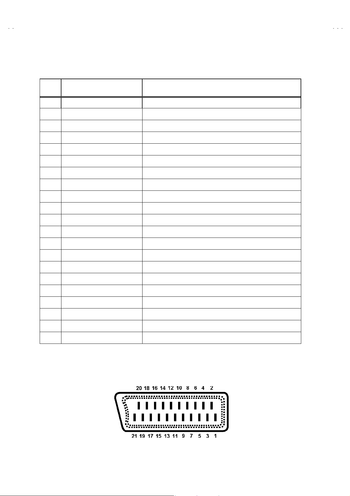
21-pin Euro connector (SCART socket)
21Pin EURO-SCART 1:
V-21BD5EKI AV-21BD5EP AV-21BD5EE
V-21BD5EKIS AV-21BD5EPS AV-21BD5EES
Pin
No.
1 Audio Output Right
2 Audio Input Right 0.5V(rms), Imp>10k
3
4Audio Earth
5Blue Earth
6 Audio Inpu t Left
7Blue Input
8 Slow Switching TV : 0-2V, AV 16/ 9 : 4.5- 7V , AV 4/3 : 9. 5-1 2V , I mp> 10k
9 Green Earth
10 NC
11 Green Input 0.7V(p-p) ±0.1V, Imp 75
12 NC
13 Red Earth
14 Blanking Earth
Signal Designation Matchin g Val ue
0.5V(rms), Imp<1kΩ (RF 54% MOD)
Ω
Audio Output!Left
0.5V(rms), Imp<1kΩ (RF 54% MOD)
0.5V(rms), Imp>10k
0.7V(p-p) ±0.1V, Imp75
Ω
Ω
Ω
Ω
15 Red Input
16 Fast Switching
17 Video Out Earth
18 Video In E arth
19 Video Output
20 Video Inpu t 1V(p-p) ±3dB, Imp75
21 Common E ar th
[
Pin assignment
0.7V(p-p) ±0.1V, Imp 75
0-0.4V : L ogic “0” , 1-3V : Logic “1” , Imp 75
1V(p-p) ±3dB, Imp75
]
Ω
Ω
Ω
Ω
No.51742
1-3
Page 4
A
V-21BD5EKI AV-21BD5EP AV-21BD5EE
A
V-21BD5EKIS AV-21BD5EPS AV-21BD5EES
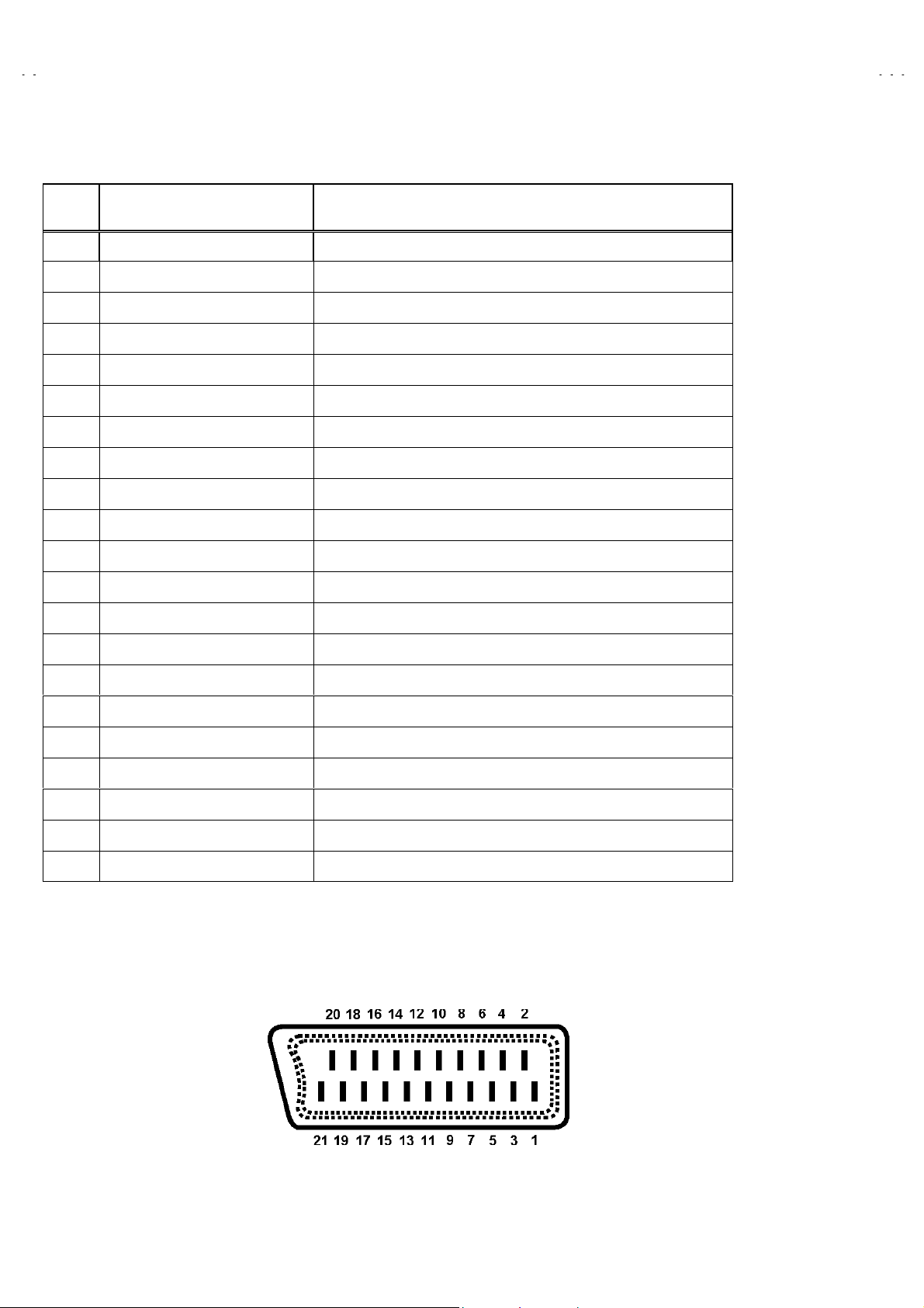
21Pin EURO-SCART 2 :
Pin
No.
1NC
2
3NC
4Audio Earth
5Earth
6 Audio Inpu t Left
7NC
8NC
9NC
10 NC
11 NC
12 NC
13 Earth
14 Earth
Signal Designation Matchin g Val ue
Audio Intput!Right
0.5V(rms), Imp<10k
0.5V(rms), Imp>10k
Ω
Ω
15 Chroma Input
16 NC
17 Earth
18 Video In E arth
19 NC
20 Video Inpu t , Y In .
21 Common E ar th
[
Pin assignment
3dB for a luminance signal of 1V(p-p)
±
1V(p-p) ±3dB, Imp75
Ω
]
1-4
No.51742
Page 5

A
V-21BD5EKI AV-21BD5EP AV-21BD5EE
A
V-21BD5EKIS AV-21BD5EPS AV-21BD5EES
SAFETY PRECAUTIONS
1. The design of this product contains special hardware, many circuits and components specially for safety purposes. For continued protection,
no changes should be made to the original design unless authorized in writing by the manufacturer. Replacement parts must be identical to
those us ed in th e origin al circ u its . Service sh oul d be perform ed by qualif i ed p ers onnel only.
2. Alt erati ons of th e desig n or circ uitr y of the pr oducts shoul d not be m ade. An y desig n alt erati ons or add itions w ill voi d the m anufactur er's
warranty and will further relieve the manufacturer of responsibility for personal injury or property damage resulting therefrom.
3. Many electrical and mechanical parts in the products have special safety-related characteristics. These characteristics are often not evident
from vis u al inspec t i on n or can th e protec ti on af forded by them neces saril y b e obt ained b y us i ng r eplacem ent c om p on ents rated for high er
voltag e, watt age, etc . Rep lac emen t part s whic h h ave th ese s pec ial saf et y ch aract eris tic s are i dentif i ed in th e par ts lis t of S ervic e manu al.
Electric al co mponents hav ing su ch f e atu r es are identif i ed by shading on t he sch em atics an d b y ( !) on the par ts list i n Serv i ce
manual.
shown in the parts list of Service manual may cause shock, fire, or other hazards.
4.
Don't short between the LIVE side ground and ISOLATED (NEUTRAL) side ground or EARTH side ground when repairing.
Some model's power circuit is partly different in the GND. The difference of the GND is shown by the LIVE : (") side GND, the
ISOLATED(NEUTRAL) : (#) side GND and EARTH : ($) side GND. Don't short between the LIVE side GND and ISOLATED(NEUTRAL)
side GND or EARTH side GND and never measure with a measuring apparatus (oscilloscope etc.) the LIVE side GND and
ISOLATED(NEUTRAL) side GND or EARTH side GND at the same time.
If above not e wi ll n ot be kept, a fuse or any parts will be brok en.
5. If any repair has been made to the chassis, it is recommended that the +B setting should be checked or adjusted (See +B ADJUSTMENT).
6. The high volt age applied t o th e picture tub e must conform with th at specifi ed in Servic e manual. Exc essive high voltage can caus e an
increas e in X- R ay emiss i on, arc ing an d poss ibl e comp onen t d amag e, th eref or e oper ati on und er exc ess ive h ig h vol tag e condi ti ons s hould
be kept t o a min imum, or sh ould b e preven ted. If s evere arci ng occurs, r emo ve the AC power imm ediatel y and determ ine t he c ause by
visual inspecti on (incorrec t inst allation , cr ack ed or melt ed hig h voltage har n ess , poor solderi ng, etc.). T o main t ain th e pr op er minimum level
of soft X-Ray em is s i on, compon en ts in t h e hi gh vol t ag e c ir c uit ry inc l ud in g the p ic ture tub e mus t be th e exact replac em en ts or alternatives
approved b y th e m an uf act urer of th e c ompl et e product.
The us e of a s ubs titut e replac em en t w hic h d oes not ha ve the same saf et y c h aracteris tics as the rec om m en d ed replac em en t part
7. Do not ch eck h ig h volt age b y dr awin g an arc. U s e a hig h vol t age meter or a hig h vol t age pr obe w ith a VT VM. Disch arg e th e picture tube
before attempting meter connection, by connecting a clip lead to the ground frame and connecting the other end of the lead throug h a 10k
2W resistor to the anode button.
8. When service is required, observe the original lead dress. Extra precaution should be given to assure correct lead dress in th e high volt ag e
circuit ar ea. W here a short c irc uit has occ urr ed, thos e c omp onent s t hat i ndic at e evid enc e of over heat ing s hou ld be r epl ac ed. A lways use
the manufacturer's replacement components.
"
No.51742
1-5
Page 6

A
V-21BD5EKI AV-21BD5EP AV-21BD5EE
A
V
A
V-21BD5EKIS AV-21BD5EPS AV-21BD5EES
FUNCTIONS
LOCAL CONTROL
FRONT
MAIN POWER
BUTTON
BACK
AERIAL TERMINAL
SCAR T JAC K 1 (AV1 )
SCAR T JAC K 2 (AV2 )
IDEO
INPUT
AUDIO
INPUT
HEAD
PHONE
STAND-BY
INDICATOR
REMOTE
SENSOR
V BUTTONVOLUME
DOWN/UP
BUTTONS
PR (PROGRAM)
DOWN/UP
BUTTONS
1-6
No. 51742
Page 7

A
A
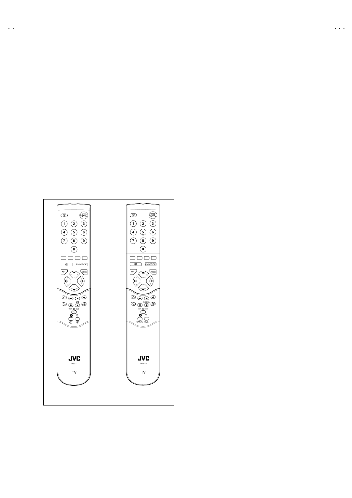
REMOTE CONTROL UNIT
V-21BD5EKI AV-21BD5EP AV-21BD5EE
V-21BD5EKIS AV-21BD5EPS AV-21BD5EES
TV mode
1. POWER
2. NUMBER 0-9 / NUMBER
3. P.MODE / OK
4. AV
5. UP
6. RIGHT
7. MENU
8. DOWN
9. LEFT
10. MUTING
11. RECALL
12. SLEEP
13. Not used
14. MOVE
15. SKIP
48B00RMC71
[EP / EPS / EE / EES]
TELETEXT mode
1. POWER
2. NUMBER 0-9
3. INDEX
4. Not used
5. UP
6. SUBPAGE
7. MENU
8. DOWN
9. HOLD
10. MUTING
11. REVEAL
12. SIZE
13. CANCEL
14. GREEN
15. RED
16. TV / TEXT
17. DELETE
18. MODE
19. VCR / / DVD switch
20. VCR / DVD Control buttons
48B00RMC72
[EKI / EKIS]
16. TV / TEXT
17. YELLOW
18. CYAN
19. VCR / / DVD switch
20. Not used
No. 51742
1-7
Page 8

A
V-21BD5EKI AV-21BD5EP AV-21BD5EE
A
V-21BD5EKIS AV-21BD5EPS AV-21BD5EES
SPECIFIC SERVICE INSTRUCTIONS
DISASSEMBLY PROCEDURE
: Before starting work, disconnect the powe r plug from the wall outlet.
Note
HOW TO REMOVE THE REAR COVER
1. Remove the 5 screws marked [A].
2. Remove the rear cover backward.
CRT SOCKET PWB
A
CRT
SPEAKER
POWER SW.
FBT
TUNER
PWB
MEMORY IC REPLAC EMENT
1. Important:
After replacing the MEMORY IC (IC702) , certainly use the JVC REMOTE CONTROL UNIT to turn on the power.
2. If other mak er (DAEW OO) REMOT E CONTR OL UNIT is in itially us ed, ther e is risk th e TV s et will no l onger op erate with t he JVC
REMOTE CONTROL UNIT.
3. If the TV set is initialized to operate with the other maker (DAEWOO) REMOTER CONTROL UNIT, there is need to yet again replace t h e
MEMORY IC (IC 70 2) .
1-8
FRONT CABINET
No.51742
Page 9
A
V-21BD5EKI AV-21BD5EP AV-21BD5EE
A
V-21BD5EKIS AV-21BD5EPS AV-21BD5EES
SERVICE ADJUSTMENTS
BEFORE ADJUSTMENT AND MAINTENANCE
1. Don't short any two soldering points or connect any component while TV set is power on.
2. Withdraw power pl ug b efore main t enance.
3. In order to ensure safety all components replaced should be identical. (For further details, refer to the component name and component No.
in PARTS LIST.)
4. Must be warm up the set for 30 minutes or more and degauss CRT thoroughly with demagnetizer coil before adjustment.
EQUIPMENT FOR ADJUSTMENT
1. Pattern Generator
2. Digital volt meter
3. Oscilloscope
4. Dema gnetizer
5. Remote control unit
48B00RMC71
Remote Control unit
48B00RMC72
No.51742
1-9
Page 10

A
V-21BD5EKI AV-21BD5EP AV-21BD5EE
A
g
V-21BD5EKIS AV-21BD5EPS AV-21BD5EES
BASIC OPERATION OF SERVICE MENU
How to ENTER and EXIT from SERVICE MODE
1. Pr ess the MUT ING KE Y and RECA LL KEY of the REMO TE
CONTOROL UNIT at the same time to display the service
MENU screen shown Fig. B.
2. When exiting from the SERVICE MODE, turn the power
switch off.
How to set SERVICE MODE
0. Select the sett ing item you want to change wit h the P.(▲)/
P.(▼) key on the REMOTE CONTROL UNIT. (The item you
selected will be indicated by YELLOW on the display.)
2. When changing the set values, use the -/ +KEY on the
REMOTE CONTROL UNIT.
3. When the s etting has been comp leted, turn th e power s witc h
off.
(The changed set values are stored in memory.)
MUTING
RECALL
SERVICE MENU screen selection
Press the P.(▲) / P.(▼) key
●
(The lett ers of t h e sel ec t ed it ems are disp l ayed in yellow )
Press the - / + key
●
・・・・・・・・・
No Adjustment item
1
AGC
2
Black R
3
Black G
4
WP Red
5
WP Green
6
WP Blue
7
H Parall (NOT USED)
8
H Bow (NOT USED)
9
H Shif t
10
V Slope
11
V Amp
12
V S Cor
13
V Shift
14
H Width (NOT USED)
15
EW Parabo (NOT USED)
16
Up Corner (NOT USED)
17
Dw Corner (NOT USED)
18
EW Trapez (NOT USED)
19
Option
select menu item.
・・・・・・
setting the value item.
Setting value
Setting value
Settin
valueSetting value
Fig. A
SERVICE
SERVICE
SERVICESERVICE
** Black R
** Black R
** Black R** Black R
SERVICE
SERVICE
SERVICESERVICE
** Black R
** Black R
** Black R** Black R
screen
screen
screenscreen
menu item
menu item
menu itemmenu item
Fig. B
1-10
No.51742
Page 11

A
V-21BD5EKI AV-21BD5EP AV-21BD5EE
A
V-21BD5EKIS AV-21BD5EPS AV-21BD5EES
ADJUSTMENTS
+B VOLTAGE CHECK
1. Receive the standard colour bar signal.
2. Conn ect digital vol tm eter betw een + of B1 Line circ uit and GN D .
3. Confirm that voltag e is DC 12 3V # 2.0V.
SCREEN
1. S et TV in AV m od e wit h out video signal ⇒ Black screen.
2. Set [WP Red], [WP Green] and [WP Blue] equal to “32”.
3. Set [Blac k R], [Bl ack G] equ al t o “8”.
4. S et TV in n orm al I m od e.
5. Adjust SCREEN VR (on FBT) such that the highest cathode cut-off voltage measured on CRT SOCKET PWB ASS’Y is DC 125V ± 5V.
WHITE BALANCE
: Confirm SC RE EN Adjust ment has b een adj us t ed.
NOTE
■■■■
LOW LIGHT
1. Input the 10-step gray scale signal. (include10% Black)
2. Enter the SERVICE MODE.
3. T ur n th e SCR EE N VR ( on FBT) grad u all y, to wher e the 2n d gray bar(1 0 % Black) f aintly visible.
4. Adjust [Black B] and [Black R] not to the colours on the gray bar.
■■■■
HIGH LIGHT
5. Apply the white signal.
6. Adjust [R DRIVE] and [G DRIVE] so that the picture becomes white.
FOCUS
1. Inp ut the crosshatch p att er n si g n al.
2. Adjust the FOCUS VR (on FBT) to have the best resolution on screen.
VERTICAL GEOMETRY
Adjust [V Amp], [V Shift] and [V Slope], [V Slope] [V S Cor] to compensate for vertical distortion.
HORIZONTAL PICTURE CENTERING
Adjust [H Shift] to have the picture in the center of the screen.
No.51742
1-11
Page 12

A
V-21BD5EKI AV-21BD5EP AV-21BD5EE
A
V-21BD5EKIS AV-21BD5EPS AV-21BD5EES
1-12
No.51742
 Loading...