

Page 1
A
V-21BD5EKI AV-21BD5EP AV-21BD5EE
A
V-21BD5EKIS AV-21BD5EPS AV-21BD5EES
SER VICE MANUAL
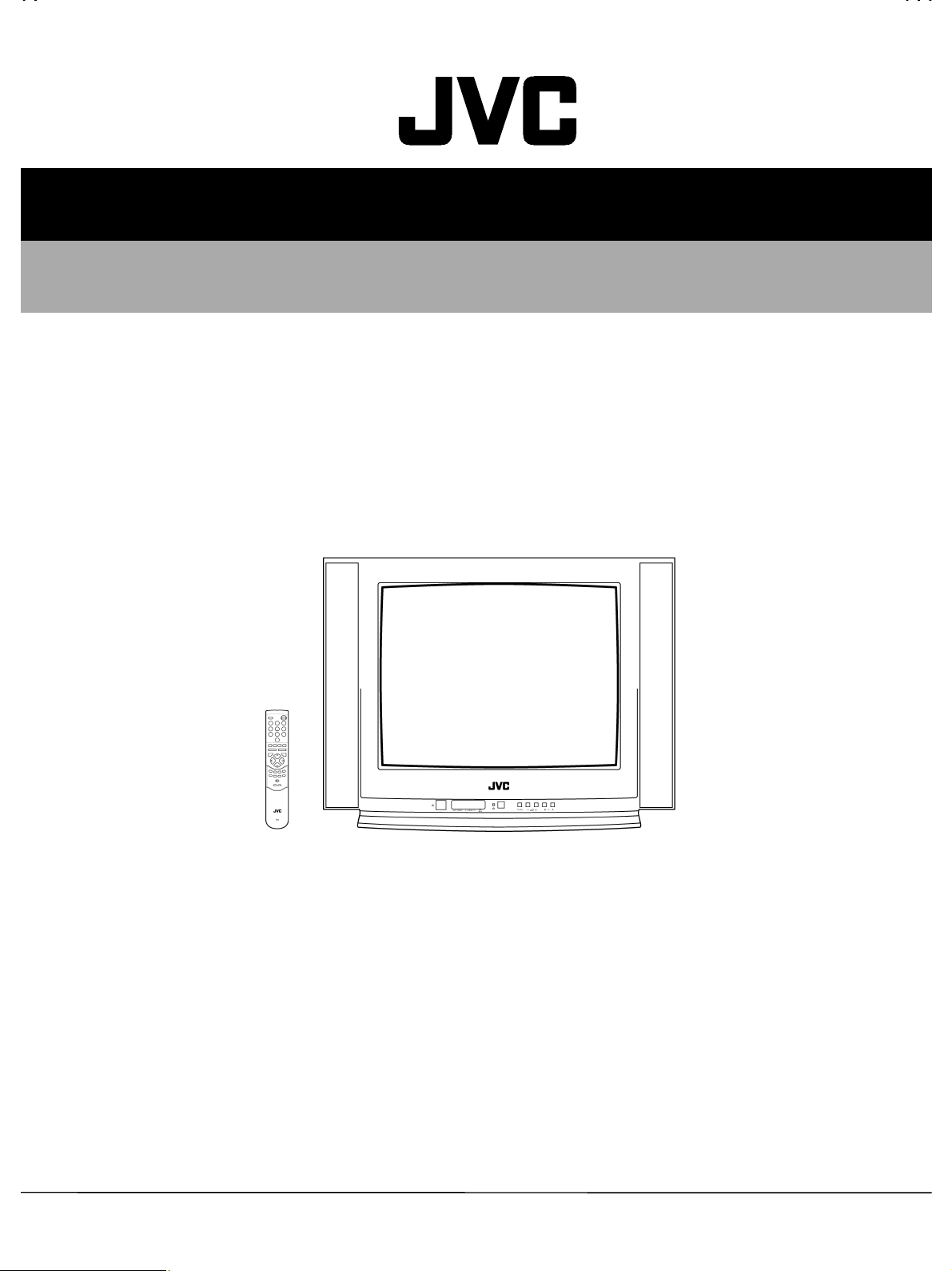
COLOUR TELEVISION
AV-21BD5EKI / AV-21BD5EP / AV-21BD5EE
AV-21BD5EKIS / AV-21BD5EPS / AV-21BD5EES
CONTENTS
SPECIFICATIONS
!
SAFETY PRECAUTIONS
!
FUNCTIONS
!
SPECIFIC SERVICE INSTRUCTIONS
!
SERVICE ADJUSTMENTS
!
★
STANDARD CIRCUIT DIAGRAM (APPENDIX)
PARTS LIST
!
1
・・・・・・・・・・・・・・・・・・・・・・・・・・・・・・・・
・・・・・・・・・・・・・・・・・・・・・・・・・・・・・・・・ ・・・・・・・・・・・・・・・・・・・・・・・・・・・・
・・・・・・・・・・・・・・・・・・・・・・・・・・・・・・・・・・・・・・・・・・・・・・・・・・・・・・・・・・・・・・・・
・・・・・・・・・・・・・・・・・・・・・・・・・・・・・・・・
・・・・・・・・・・・・・・・・・・・・・・・・・・・・・・・・ ・・・・・・・・・・・・・・・・・・・・・・
・・・・・・・・・・・・・・・・・・・・・・・・・・・・・・・・・・・・・・・・・・・・・・・・・・・・・・・・・・・・・・・・
・・・・・・・・・・・・・・・・・・・・・・・・・・・・・・・・
・・・・・・・・・・・・・・・・・・・・・・・・・・・・・・・・ ・・・・・・・・・・・・・・・・・・・・・・・・・・・・・・・・
・・・・・・・・・・・・・・・・・・・・・・・・・・・・・・・・・・・・・・・・・・・・・・・・・・・・・・・・・・・・・・・・
・・・・・・・・・・・・・・・・・・・・・・・・・・・・・・・・
・・・・・・・・・・・・・・・・・・・・・・・・・・・・・・・・ ・・・・・・・・・・・・
・・・・・・・・・・・・・・・・・・・・・・・・・・・・・・・・・・・・・・・・・・・・・・・・・・・・・・・・・・・・・・・・
・・・・・・・・・・・・・・・・・・・・・・・・・・・・・・・・
・・・・・・・・・・・・・・・・・・・・・・・・・・・・・・・・ ・・・・・・・・・・・・・・・・・・・・・
・・・・・・・・・・・・・・・・・・・・・・・・・・・・・・・・・・・・・・・・・・・・・・・・・・・・・・・・・・・・・・・・
・・・・・・・・・・・・・・・・・・・・・・・・・・・・・・・・
・・・・・・・・・・・・・・・・・・・・・・・・・・・・・・・・ ・・・・・
・・・・・・・・・・・・・・・・・・・・・・・・・・・・・・・・・・・・・・・・・・・・・・・・・・・・・・・・・・・・・・・・
・・・・・・・・・・・・・・・・・・・・・・・・・・・・・・・・
・・・・・・・・・・・・・・・・・・・・・・・・・・・・・・・・ ・・・・・・・・・・・・・・・・・・・・・・・・・・・・・・・・
・・・・・・・・・・・・・・・・・・・・・・・・・・・・・・・・・・・・・・・・・・・・・・・・・・・・・・・・・・・・・・・・
COPYRIGHT © 2000 VICTOR COMPANY OF JAPAN, LTD.
・・・・・・・・・・・・・・・・・・・・・・・・・・・・
・・・・・・・・・・・・・・・・・・・・・・・・・・・・・・・・・・・・・・・・・・・・・・・・・・・・・・・・
・・・・・・・・・・・・・・・・・・・・・・
・・・・・・・・・・・・・・・・・・・・・・・・・・・・・・・・・・・・・・・・・・・・
・・・・・・・・・・・・・・・・・・・・・・・・・・・・・・・・ ・・・・
・・・・・・・・・・・・・・・・・・・・・・・・・・・・・・・・・・・・・・・・・・・・・・・・・・・・・・・・・・・・・・・・
・・・・・・・・・・・・
・・・・・・・・・・・・・・・・・・・・・・・・
・・・・・・・・・・・・・・・・・・・・・
・・・・・・・・・・・・・・・・・・・・・・・・・・・・・・・・・・・・・・・・・・
・・・・・
・・・・・・・・・・
・・・・・・・・・・・・・・・・・・・・・・・・・・・・・・・・
・・・・・・・・・・・・・・・・・・・・・・・・・・・・・・・・・・・・・・・・・・・・・・・・・・・・・・・・・・・・・・・・
1-2
1-5
1-6
1-8
1-9
2-1
1-15
No.51742
Jul. 2000
Page 2
A
V-21BD5EKI AV-21BD5EP AV-21BD5EE
A
V-21BD5EKIS AV-21BD5EPS AV-21BD5EES
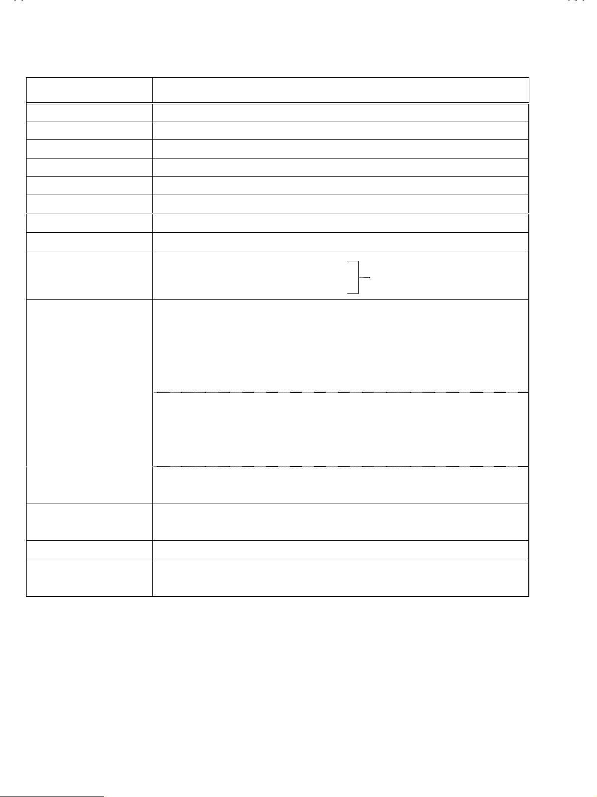
SPECIFICATIONS
Item Content
TV RF SYSTEM
COLOUR STANDARD
POWER INPUT
POWER CONSUMPTION
TELETEXT SYSTEM
SOUND OUTPUT / SPEAKER
PICTURE TUBE SIZE
ANTENNA INPUT
INPUT / OUTPUT
INTERMEDIATE FREQUENCIES
B/G, I, D/K & L/L’
PAL / SECAM / NTSC (AV only)
AC 230V, 50Hz
49W / 3W (STBY)
FLOF (Fastext) / TOP / WST (standard system)
7W / 8Ω (×2)
VISIBLE AREA 51cm (measured diagonally)
75Ω Unbalanced
FRONT: RCA JACK (VIDEO / AUDIO)
REAR : 21-PIN EURO CONNECTOR (SCART)×2
(VIDEO / AUDIO / RGB / S. VHS)
PIF : 38.9MHz (B/G, D/K, I, L) , 33.9MHz (L’)
SIF :33.4MHz (PAL / SECAM – B/G)
32.9MHz (PAL / SECAM – I / I)
32.4MHz (PAL / SECAM – D/K, SECAM – L)
40.4MHz (SEC AM – L’)
SOUND SUBCARRIER : 5.5MHz (PAL / SECAM – B/G)
COMMON INPUT
6.0MHz (PAL / SECAM – I / I)
6.5MHz (PAL / SECAM – D/K, SECAM – L)
6.5MHz (SECAM – L’)
COLOUR SUBCARRIER : 4.43MHz (PAL)
4.250MHz, 4.406MHz (SECAM)
REMOTE CONTROL
DIMENSIONS (W
MASS
××××H××××
D)
RM-C71 [ Batt, AAA (R03) ] (EP, EPS, EE, EES)
RM-C72 [ Batt, AAA (R03) ] (EKI, EKIS)
615mm×480mm×480mm
20.3kg
Design & specifications are subject to change wit hout notice
.
1-2
No.51742
Page 3
A
A
■
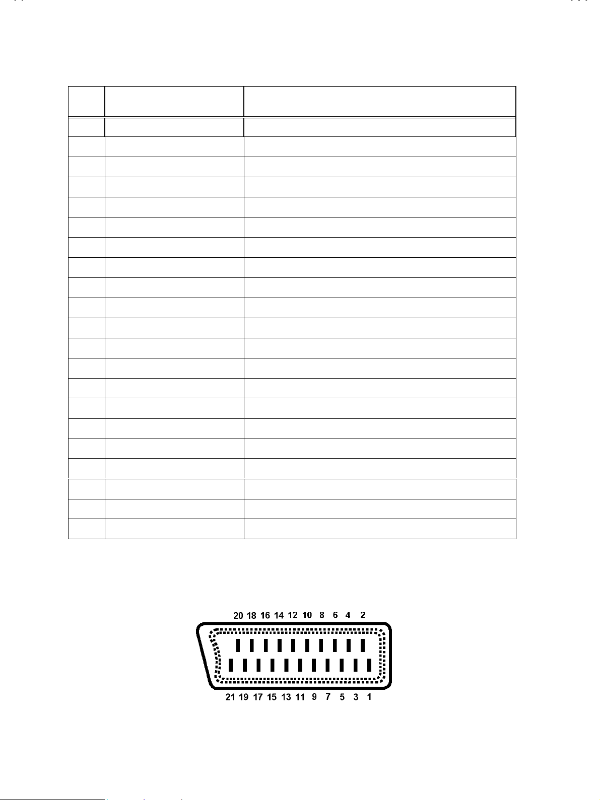
21-pin Euro connector (SCART socket)
21Pin EURO-SCART 1:
V-21BD5EKI AV-21BD5EP AV-21BD5EE
V-21BD5EKIS AV-21BD5EPS AV-21BD5EES
Pin
No.
1 Audio Output Right
2 Audio Input Right 0.5V(rms), Imp>10k
3
4Audio Earth
5Blue Earth
6 Audio Inpu t Left
7Blue Input
8 Slow Switching TV : 0-2V, AV 16/ 9 : 4.5- 7V , AV 4/3 : 9. 5-1 2V , I mp> 10k
9 Green Earth
10 NC
11 Green Input 0.7V(p-p) ±0.1V, Imp 75
12 NC
13 Red Earth
14 Blanking Earth
Signal Designation Matchin g Val ue
0.5V(rms), Imp<1kΩ (RF 54% MOD)
Ω
Audio Output!Left
0.5V(rms), Imp<1kΩ (RF 54% MOD)
0.5V(rms), Imp>10k
0.7V(p-p) ±0.1V, Imp75
Ω
Ω
Ω
Ω
15 Red Input
16 Fast Switching
17 Video Out Earth
18 Video In E arth
19 Video Output
20 Video Inpu t 1V(p-p) ±3dB, Imp75
21 Common E ar th
[
Pin assignment
0.7V(p-p) ±0.1V, Imp 75
0-0.4V : L ogic “0” , 1-3V : Logic “1” , Imp 75
1V(p-p) ±3dB, Imp75
]
Ω
Ω
Ω
Ω
No.51742
1-3
Page 4
A
V-21BD5EKI AV-21BD5EP AV-21BD5EE
A
V-21BD5EKIS AV-21BD5EPS AV-21BD5EES
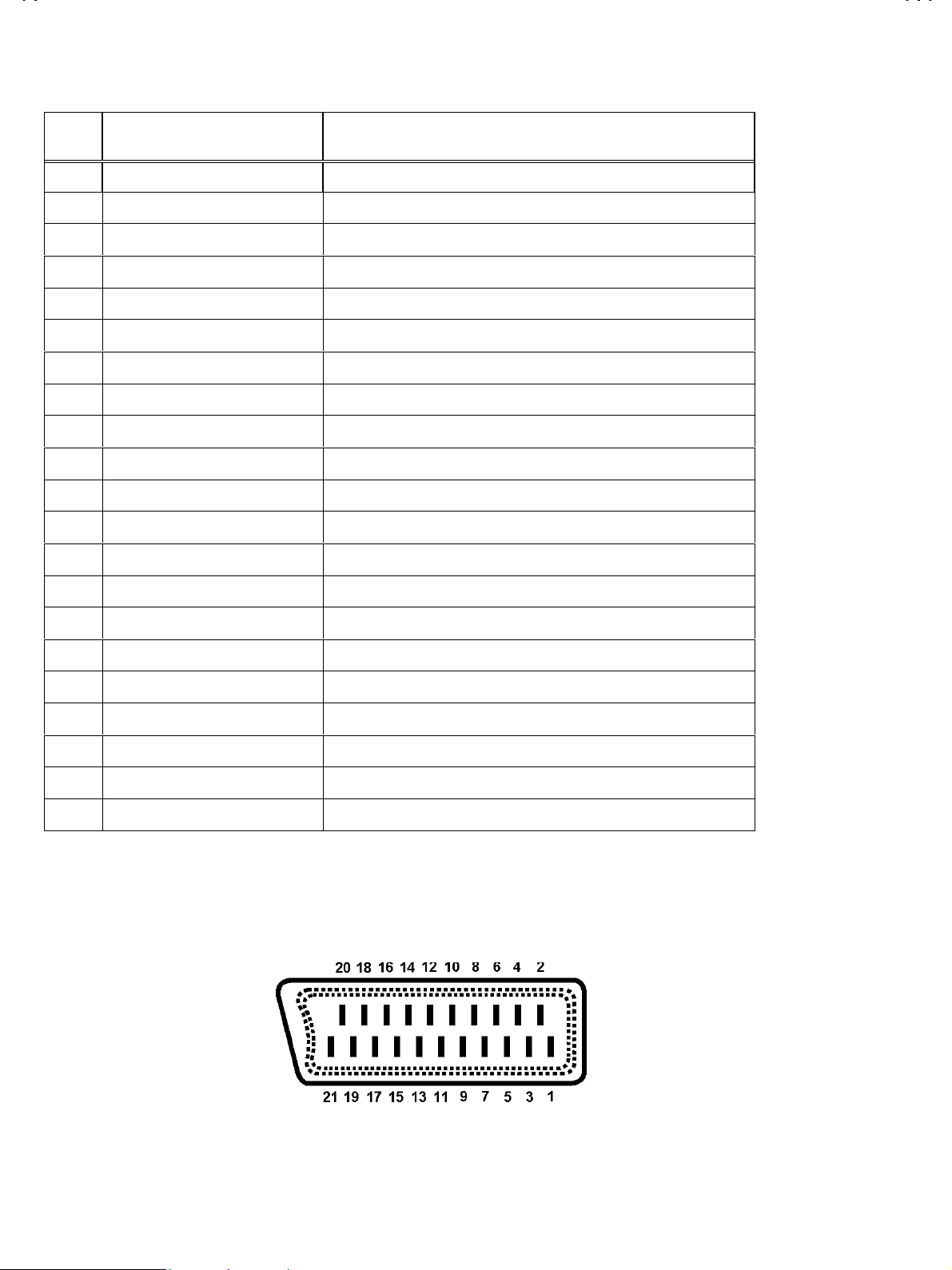
21Pin EURO-SCART 2 :
Pin
No.
1NC
2
3NC
4Audio Earth
5Earth
6 Audio Inpu t Left
7NC
8NC
9NC
10 NC
11 NC
12 NC
13 Earth
14 Earth
Signal Designation Matchin g Val ue
Audio Intput!Right
0.5V(rms), Imp<10k
0.5V(rms), Imp>10k
Ω
Ω
15 Chroma Input
16 NC
17 Earth
18 Video In E arth
19 NC
20 Video Inpu t , Y In .
21 Common E ar th
[
Pin assignment
3dB for a luminance signal of 1V(p-p)
±
1V(p-p) ±3dB, Imp75
Ω
]
1-4
No.51742
Page 5

A
V-21BD5EKI AV-21BD5EP AV-21BD5EE
A
V-21BD5EKIS AV-21BD5EPS AV-21BD5EES
SAFETY PRECAUTIONS
1. The design of this product contains special hardware, many circuits and components specially for safety purposes. For continued protection,
no changes should be made to the original design unless authorized in writing by the manufacturer. Replacement parts must be identical to
those us ed in th e origin al circ u its . Service sh oul d be perform ed by qualif i ed p ers onnel only.
2. Alter ations of th e desi gn or cir cuitr y of th e product s shoul d not b e made. A ny des ign alt erati ons or add itions will void the m anufactu rer's
warranty and will further relieve the manufacturer of responsibility for personal injury or property damage resulting therefrom.
3. Many electrical and mechanical parts in the products have special safety-related characteristics. These characteristics are often not evident
from vis u al inspec t i on n or can th e protec ti on af forded by them neces saril y b e obt ained b y us i ng r eplacem ent c om p on ents rated for high er
voltag e, watt age, etc . Rep lac emen t part s whic h h ave th ese s pec ial saf et y ch aract eris tics are i dentif i ed in th e par ts lis t of S ervic e manu al.
Electric al co mponents hav ing su ch f e atu r es are identif i ed by shading on t he sch em atics an d b y ( !) on the par ts list i n Serv i ce
manual.
shown in the parts list of Service manual may cause shock, fire, or other hazards.
4.
Don't short between the LIVE side ground and ISOLATED (NEUTRAL) side ground or EARTH side ground when repairing.
Some model's power circuit is partly different in the GND. The difference of the GND is shown by the LIVE : (") side GND, the
ISOLATED(NEUTRAL) : (#) side GND and EARTH : ($) side GND. Don't short between the LIVE side GND and ISOLATED(NEUTRAL)
side GND or EARTH side GND and never measure with a measuring apparatus (oscilloscope etc.) the LIVE side GND and
ISOLATED(NEUTRAL) side GND or EARTH side GND at the same time.
If above not e wi ll n ot be kept, a fuse or any parts will be brok en.
5. If any repair has been made to the chassis, it is recommended that the +B setting should be checked or adjusted (See +B ADJUSTMENT).
6. The high vol tage appli ed to the pictu re tube must conf orm with that spec ified in Servic e manual. Excess ive high voltage c an cause an
increas e in X- R ay emiss i on, arc ing an d poss ibl e comp onen t d amag e, th eref or e oper ati on und er exc ess ive h ig h vol tag e condi ti ons s hould
be kept t o a min imum, or sh ould b e preven ted. If s evere arci ng occurs, r emo ve the AC power imm ediatel y and determ ine t he c ause by
visual inspecti on (incorrec t inst allation , cr ack ed or melt ed hig h voltage har n ess , poor solderi ng, etc.). T o main t ain th e pr op er minimum level
of soft X-Ray em is s i on, compon en ts in t h e hi gh vol t ag e c ir c uit ry inc l ud in g the p ic ture tub e mus t be th e exact replacements or alternatives
approved b y th e m an uf act urer of th e c ompl et e product.
The us e of a s ubs titut e replac em en t w hic h d oes not ha ve the same saf et y c h aracteris tics as the rec om m en d ed replac em en t part
7. Do not c h eck h igh vol tag e by dr awin g an arc . Us e a h igh volt ag e meter or a high volt ag e prob e with a VT V M. Disc har ge t he pic ture tube
before attempting meter connection, by connecting a clip lead to the ground frame and connecting the other end of the lead throug h a 10k
2W resistor to the anode button.
8. When service is required, observe the original lead dress. Extra precaution should be given to assure correct lead dress in t he high volt ag e
circuit ar ea. W here a short c irc uit has occ urr ed, thos e c omp onent s t hat i ndic at e evid enc e of over heat ing s hou ld be r epl ac ed. A lways use
the manufacturer's replacement components.
"
No.51742
1-5
Page 6
A
V-21BD5EKI AV-21BD5EP AV-21BD5EE
A
V
A
V-21BD5EKIS AV-21BD5EPS AV-21BD5EES
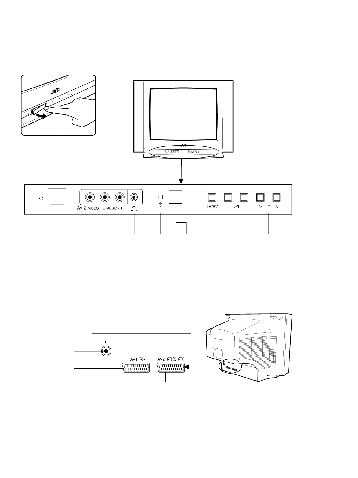
FUNCTIONS
LOCAL CONTROL
FRONT
MAIN POWER
BUTTON
BACK
AERIAL TERMINAL
SCAR T JAC K 1 (AV1 )
SCAR T JAC K 2 (AV2 )
IDEO
INPUT
AUDIO
INPUT
HEAD
PHONE
STAND-BY
INDICATOR
REMOTE
SENSOR
V BUTTONVOLUME
DOWN/UP
BUTTONS
PR (PROGRAM)
DOWN/UP
BUTTONS
1-6
No. 51742
Page 7
A
A
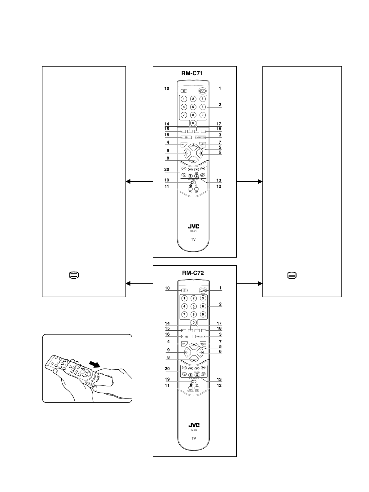
REMOTE CONTROL
V-21BD5EKI AV-21BD5EP AV-21BD5EE
V-21BD5EKIS AV-21BD5EPS AV-21BD5EES
TV mode
1. POWER
2. NUMBER 0-9 / NUMBER
3. P.MODE / OK
4. AV
5. UP
6. RIGHT
7. MENU
8. DOWN
9. LEFT
10. MUTING
11. RECALL
12. SLEEP
13. Not used
14. MOVE
15. SKIP
TELETEXT mode
1. POWER
2. NUMBER 0-9
3. INDEX
4. Not used
5. UP
6. SUBPAGE
7. MENU
8. DOWN
9. HOLD
10. MUTING
11. REVEAL
12. SIZE
13. CANCEL
14. GREEN
15. RED
16. TV / TEXT
17. DELETE
18. MODE
19. VCR / / DVD switch
20. VCR / DVD Control buttons
16. TV / TEXT
17. YELLOW
18. CYAN
19. VCR / / DVD switch
20. Not used
No. 51742
1-7
Page 8
A
V-21BD5EKI AV-21BD5EP AV-21BD5EE
A
V-21BD5EKIS AV-21BD5EPS AV-21BD5EES
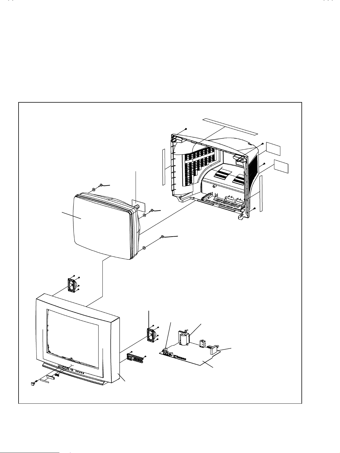
SPECIFIC SERVICE INSTRUCTIONS
DISASSEMBLY PROCEDURE
Note : Before startin g w ork, disc onnect the p ow er pl ug from the w all outl et .
HOW TO REMOVE THE REAR COVER
1. Remove the 5 screws marked A.
2. Remove the rear cover backward.
CRT
CRT SOCKET PWB
SPEAKER
POWER SW.
A
FBT
TUNER
PWB
FRONT CABINET
1-8
No.51742
Page 9
A
V-21BD5EKI AV-21BD5EP AV-21BD5EE
A
V-21BD5EKIS AV-21BD5EPS AV-21BD5EES
SERVICE ADJUSTMENTS
BEFORE ADJUSTMENT AND MAINTENANCE
1. Don't short any two soldering points or connect any component while TV set is power on.
2. Withdraw power pl ug b efore main t enance.
3. In order to ensure safety all components replaced should be identical. (For further details, refer to the component name and component No.
in PARTS LIST.)
4. Must be warm up the set for 30 minutes or more and degauss CRT thoroughly with demagnetizer coil before adjustment.
EQUIPMENT FOR ADJUSTMENT
1. Pattern Generator
2. Digital volt meter
3. Oscilloscope
4. Dema gnetizer
5.
6. Remote controller (RM-C71 or RM-C72)
remote controller (For repair service)
Service
ADJUSTMENTS PROCEDURES
+B VOLTAGE CHECK
1. Receive a standard colour bar signal.
2. Connect digital volt meter between + of B1 Line circuit and GND.
3. Confirm that voltage is DC 123V # 2.0V.
(RM-C71)
(RM-C72)
No.51742
Service Remote ControllerRemote Controller
1-9
Page 10

A
V-21BD5EKI AV-21BD5EP AV-21BD5EE
A
g
V-21BD5EKIS AV-21BD5EPS AV-21BD5EES
BASIC OPERATION OF SERVICE MENU
REMOTE CONTROLLER (RM-C71, RM-C72)
How to ENTER and EXIT from service mode
1. Select the CH-91.
2. Press the MENU KEY of the remote control unit and select
PICTURE from the MENU with the P.(▲)/ P.(▼) key of the
remote c ontrol unit .
3. While pressing the P. MODE/OK KEY of the remote control unit,
select "sharpness" from the MENU with the P.(▲)/ P.(▼) /
-/ + key. Then, set th e set valu e of "sh arpness " to "0" with
the -/ +KEY.
4. Press the MENU KEY of th e rem ot e control un it t wice and ret ur n
to the normal screen. To enter the SERVICE MODE, change the
indic ation of RED , GREEN and MEN U, in turn, with th e key of
the remote control unit.
5. When e xiting f rom t he SER VICE MOD E, tur n the p ower s witch
off.
How to set SERVICE MODE
1. Select the settin g item you wan t to change with th e P.(▲)/ P.(▼)
key on the rem ote control unit. (The item you selected will b e
indi cated by YELLOW on t he display.)
2. When changing the set values, use the -/ +KEY on the
remote control unit.
3. When the setting has been completed, turn the power switch off.
(The changed set values are stored in memory.)
SERVICE MENU screen selection
Press the P.(▲)/ P.(▼) key
(The lett ers of t h e sel ec t ed it ems are disp l ayed in yellow )
Press the -/ +KEY
AGC
・
Black R
・
Black G
・
WP Red
・
WP Green
・
WP Blue
・
H Parall
・
H Bow
・
H Shift
・
V Slope
・
V Amp
・
・・・・・・・・・・
・・・・・・・・・・・
VS Cor
・
V Shift
・
H Width
・
EW Parabo
・
Up Corner
・
Dw Corner
・
EW Trapez
・
Option
・
select menu item.
setting the value i t em.
Setting value
Setting value
Settin
valueSetting value
SERVICE
SERVICE
SERVICESERVICE
** Black R
** Black R
** Black R** Black R
SERVICE
SERVICE
SERVICESERVICE
** Black R
** Black R
** Black R** Black R
screen
screen
screenscreen
menu item
menu item
menu itemmenu item
1-10
No.51742
Page 11

A
V-21BD5EKI AV-21BD5EP AV-21BD5EE
A
A
A
A
V-21BD5EKIS AV-21BD5EPS AV-21BD5EES
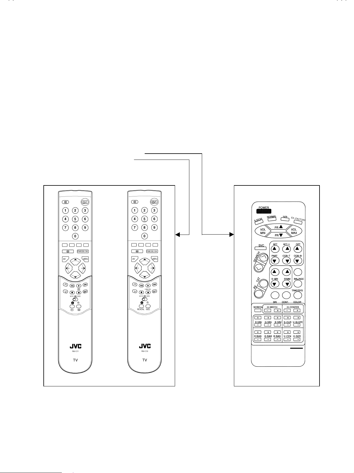
FUNCTION OF SERVICE REMOTE CONTROLLER
POWER : Power On/Off key
S STOP : User R/C mode change (DW→JVC→AIWA)
NORMAL : NORMALⅠ→NORMALⅡ→Favorite
H/R : Fast heat-run mode in line production
EX-FACTORY : Not use
VOL MIN : Volume min i mu m key
VOL MAX : Volum e maximu m k ey
PR+ : Program up key
PR- : Program down key
SVC : Service mode On/Off key
FT : AFT adj us t m en t k ey
FT-L : SECAM L AFT adjustment key
OPT : AGC adjus tment k ey
PART : Not use
COR-T : Not use
COR-B : Not use
SEARCH : Search up/down key
V : AV mode/TV mode t oggl e key
TXT : Teletext On/Off key
S-BRI : Sub-brig ht ness adjus tment key
SYMM : Not use
BAL / AGC : LED EAST Yes/No toggle key
BRI : Bri gh t n ess Mi n/Max t ogg le key
CONT : Contrast Min/Max toggle key
COLOR : Color Min/ M ax toggl e key
SCREEN : Horizontal 1 line display key for screen adjustment
H-W IDT H : H. width ad jus t m ent k ey
H-CENTER : H. center adjustment key
R DRV : R drive adjustment key for W/B high beam
G DRV : G drive adjustment key for W/B high beam
B DRV : B drive adjustment key for W/B high beam
(Do not adjust : B is the reference)
R BIAS : R bias adjustment key for W/B low beam
Service Remote Controller
G BIAS : G bias adjustment key for W/B low beam
B BIAS : B bias adjustment key for W/B low beam
(Do not adjust : B is the reference)
S-CUR : Not use
V-SLOPE : Not use
V-CEN : Vertical center adjustment key
V-SIZ E : Vertical size adjustment key
No.51742
1-11
Page 12

A
V-21BD5EKI AV-21BD5EP AV-21BD5EE
A
V-21BD5EKIS AV-21BD5EPS AV-21BD5EES
ADJUSTMENTS
SELECT OPTION ITEM
Option Tuner maker Cut off / video Amp.
0 DAEWOO / SAMSUNG 140V / 92V
2 SIEL 140V / 92V
G2 ALIGNMENT
TV in AV mode without video signal ⇒ Black screen.
1
TV preset with WP Red, WP Green and WP Blue equal to 32.
2
TV preset with Black R, Black G equal to 8.
3
Set TV in NORMAL I mode.
4
Adjust screen volume (on FBT) such that the highest cathode cut-off voltage measured on CRT board, is Vcut off ±5V.
5
Screen siz e Vcut-off
21
””””
125V
WHITE BALANCE
NOTE
■■■■
Low Light
Press the T V / AV but ton on the front of the TV unit an d en ter the VIDE O MO D E.
1
Input a crosshatch pattern signal.
2
Press the SVC key to display the SVC screen as shown in Fig.1.
3
Press the SCREEN key to display the single horizontal line.
4
Check the c ol or of t h e si ng l e hor i z ontal line b ein g dis pl ayed.
5
Press the SCREEN key to disappear the single horizontal line.
6
Adjust the bias values of R, G and B with their respective +/- keys so that the single horizontal line on the screen becomes “white”.
7
While pressing the SCREEN key, check the color of the single horizontal line on the screen.
8
Repeat the steps
9
When the WHITE BALANCE adjustments are carried out, it is necessary to use the service remocon.
●
Confirm G2 Alignment has been adjusted.
●
above unt il th e si ng le horiz ont al line on the screen bec om es “white”.
5~8
1-12
No.51742
Page 13

A
V-21BD5EKI AV-21BD5EP AV-21BD5EE
A
V-21BD5EKIS AV-21BD5EPS AV-21BD5EES
■■■■
High Light
Press the SCR EE N k ey t o dis pl ay t h e si ng le horiz ont al line.
⑩
In the same manner as for “Low Light”, adjust R DRIVE and G DRIVE with their respective +/- keys.
⑪
When the adjust m ent h as b een c o mp l eted, press th e SVC but ton to exit from the ADJ’MENT MODE.
⑫
FOCUS
Input a crosshatch pattern signal
1
Adjust the FOCUS volume (on FBT) to have the best resolution on screen.
2
VERTICAL GEOMETRY
Adjust the V Amp, V Shift, VSC or and V slope to compensate for vertical distortion.
HORIZONTAL PICTURE CENTERING
Adjust H Shift, to have the picture in the center of the screen.
No.51742
1-13
Page 14

A
V-21BD5EKI AV-21BD5EP AV-21BD5EE
A
V-21BD5EKIS AV-21BD5EPS AV-21BD5EES
EAST / WEST CORRECTION
Adjust the H. Parall, H. Bow, H. Widdth, EW. Parabo, Up corner, Dw Corner, EW Trapez to compensate for geometrical distortion.
1-14
No.51742
Page 15

A
V-21BD5EKI AV-21BD5EP AV-21BD5EE
A
V-21BD5EKIS AV-21BD5EPS AV-21BD5EES
PARTS LIST
CAUTION
T he parts id entifi ed by the ! symb ol are i mportant for the s afety . W henever rep lacing t hese par ts, be s ure to us e specif ied on es to
!
secure the safety .
The parts not indicated in this Parts List and those which are filled with lines --- in the Parts No. columns will not be supplied .
!
P. W. Board Ass'y will not be supplied, but those which are filled with the Parts No. in the Parts No. columns will be supplied .
!
ABBREVIATIONS OF RESISTORS, TRANSISTOR, CAPACITORS AND TOLERANCES
RESISTORS CAPACITORS
C R Carbon Resistor CERA C Ceramic Capacitor
V R Variable Resistor ELECTRO C Electrolyti c Capacitor
MYLAR C Mylar Capacitor
TR Transistor
TOLERANCES
FGJKMNRHZP
1%
±
2%
±
5%
±
10%
±
20%
±
30%
±
+30%
-10%
+50%
-10%
+80%
-20%
+100%
0%
No. 51742
1-15
Page 16

A
V-21BD5EKI AV-21BD5EP AV-21BD5EE
A
V-21BD5EKIS AV-21BD5EPS AV-21BD5EES
■■■■
PACKING & EXPLODED VIEW PARTS LIST
Ref. Symbol No. Part No. Part Name Description
!
1 M211 4852157801 COVER BACK HIPS BK
!
2 M541 4855415800 SPEC PLATE 150ART P/E FILM (C/TV)
!
3 M781 4857817612 CLOTH BLACK FELT 250X20X0.7
4 CRT1A 4856013300 SCREW CRT FIXING 30X80 BK
5 CRT1C 4856013303 SCREW CRT FIXING 30X250 YL
7M191 4851941501 BUTTON CTRL 4947801+5542600
8M211A7172401412 SCREW TAPPTITE TT2 TRS 4X14 MFZN BK
9 M481 4854858301 BUTTON POWER ABS BK
10 M481A 4856715600 SPRING SWPA PIE 0.4
11 M561 4855622500 MARK BRAND AL DIA-CUT GOLD
12 M751 4857538201 COVER JACK HIPS BK
13 SP01B7178301011 SCREW TAPPTITE TT2 WAS 3X10 MFZN
13 SP02A 7178301011 SCREW TAPPTITE TT2 WAS 3X10 MFZN
14 V901 4859629361 CRT(ITC) A51EFS83X191
!
15 M201 4852076001 MASK FRONT HIPS BK
!
16 SP01 4858310910 SPEAKER 7.5W 8 OHM 95BF03LC
17 SP02 4858310910 SPEAKER 7.5W 8 OHM 95BF03LC
18 M801 4858058500 BOX CARTON DW-3
19M811 4858195500 PAD EPS
20 M821 4858211800 BAG P.E L.D.P.E T0.03X1300X1000
21 M822 4858213800 BAG INSTRUCTION L.D.P.E T0.05X250X400
22 10000 48586054K1 MANUAL INSTRUCTION DTM-2082CW
!
23 ZZ100 48B00RMC71 TRANSMITTER REMOCON RM-C71 (AAA)
!
■■■■
PACKING
ZZ131 58G0000147 COIL DEGAUSSING DC-21SF
21!22
19
19
23
20
19
18
1-16
No.51742
Page 17

A
A
■■■■
EXPLODED VIEW
V-21BD5EKI AV-21BD5EP AV-21BD5EE
V-21BD5EKIS AV-21BD5EPS AV-21BD5EES
!
14
8
!
1
3
6
4
CRT SOCKET PWB
5
3
!
2
3
!
15
10
17
12
11
16
7
13
POWER SW.
FBT
TUNER
PWB
No.51742
1-17
Page 18

A
V-21BD5EKI AV-21BD5EP AV-21BD5EE
A
V-21BD5EKIS AV-21BD5EPS AV-21BD5EES
■■■■
ELECTRICAL PARTS LIST
Symbol No. Part No. Part Name Description
!
C101 CEXF1H100V C ELECTRO 50V RSS 10MF (5X11) TP
C102 CEXF1H470V C ELECTRO 50V RSS 47MF (6.3X11) TP
C103 CCZB1H102K C CERA 50V B 1000PF K (AXIAL)
C104 CCXB1H102K C CERA 50V B 1000PF K (TAPPING)
C106 CEXF1E221V C ELECTRO 25V RSS 220MF (8X11.5) TP
C108 CCZB1H101 K C CERA 50V B 100PF K (AXIAL)
C110 CCZB1H102K C CERA 50V B 1000PF K (AXIAL)
C120 CCXB1H102K C CERA 50V B 1000PF K (TAPPING)
C121 CEXF1H100V C ELECTRO 50V RSS 10MF (5X11) TP
C305 CEXF1E221V C ELECTRO 25V RSS 220MF (8X11.5) TP
C313 CMXM2A104J C MYLAR 100V 0.1MF J TP
C315 CEXF2C470C C ELECTRO 160V RUS 47MF (13X25) TP
C320 CBXF1H104Z C CERA SEMI 50V F 0.1MF Z (TAPPING)
C350 CCXF1H473Z C CERA 50V F 0.047MF Z (TAPPING)
C351 CCXF1H473Z C CERA 50V F 0.047MF Z (TAPPING)
C390 CMXM2A473J C MYLAR 100V 0.047MF J TP
C401 CEXF1H470V C ELECTRO 50V RSS 47MF (6.3X11) TP
C404 CMYH3C752J C MYLAR 1.6KV BUP 7500PF J
C408 CMYE2E364J C MYLAR 250V PU 0.36MF J
C412 CEXF2C339V C ELECTRO 160V RSS 3.3MF (8X16) TP
C414 CMXM2A104J C MYLAR 100V 0.1MF J (TP)
C415 CEXF2E479V C ELECTRO 250V RSS 4.7MF (10X16)TP
C417 CMXL2E104K C MYLAR 250V MEU 0.1MF K
C418 CCXB1H102K C CERA 50V B 1000PF K (TAPPING)
C420 CCXB2H222K C CERA 500V B 2200PF K (TAPPING)
C500 CEXF1H478V C ELECTRO 50V RSS 0.47MF (5X11) TP
C501 CEXF1H100V C ELECTRO 50V RSS 10MF (5X11) TP
C509 CXCH1H270J C CERA 50V CH 27PF J (TAPPING)
C511 CMXB1H224J C MYLAR 50V EU 0.22MF J (TP)
C512 CMXB1H224J C MYLAR 50V EU 0.22MF J (TP)
C513 CBXF1H104Z C CERA SEMI 50V F 0.1MF Z (TAPPING)
C514 CEXF1E101V C ELECTRO 25V RSS 100MF (6.3X11) TP
C515 CBZR1C222M C CERA 16V Y5R 2200PF M (AXIAL)
C516 CBZR1C472M C CERA 16V Y5R 4700PF M (AXIAL)
C517 CEXF1H109V C ELECTRO 50V RSS 1MF (5X11) TP
C518 CBZF1H104Z C CERA SEMI 50V F 0.1MF Z
C519 CEXF1H109V C ELECTRO 50V RSS 1MF (5X11) TP
C520 CCZB1H102K C CERA 50V B 1000PF K (AXIAL)
C521 CCZB1H102K C CERA 50V B 1000PF K (AXIAL)
C522 CEXF1H479V C ELECTRO 50V RSS 4.7MF (5X11) TP
C523 CBZF1H104Z C CERA SEMI 50V F 0.1MF Z
C524 CMXB1H104J C MYLAR 50V EU 0.1MF J (TP)
C525 CCXB1H102K C CERA 50V B 1000PF K (TAPPING)
C526 CMXB1H104J C MYLAR 50V EU 0.1MF J (TP)
C527 CMXB2A473J C MYLAR 100V EU 0.047MF J (TP)
C528 CEXF1E101V C ELECTRO 25V RSS 100MF (6.3X11) TP
C529 CBZF1H104Z C CERA SEMI 50V F 0.1MF Z
C530 CEXF1E101V C ELECTRO 25V RSS 100MF (6.3X11) TP
C531 CCXF1H473Z C CERA 50V F 0.047MF Z (TAPPING)
C532 CEXF1H100V C ELECTRO 50V RSS 10MF (5X11) TP
C533 CCZB1H102K C CERA 50V B 1000PF K (AXIAL)
C534 CCZF1H223Z C CERA 50V F 0.022MF Z
C535 CCZF1H223Z C CERA 50V F 0.022MF Z
C536 CCZF1H223Z C CERA 50V F 0.022MF Z
C537 CBXF1H104Z C CERA SEMI 50V F 0.1MF Z (TAPPING)
C540 CEXF1H220V C ELECTRO 50V RSS 22MF (5X11) TP
C541 CEXF1H220V C ELECTRO 50V RSS 22MF (5X11) TP
C542 CEXF1H100V C ELECTRO 50V RSS 10MF (5X11) TP
C543 CEXF1H100V C ELECTRO 50V RSS 10MF (5X11) TP
C550 CEXF1H229V C ELECTRO 50V RSS 2.2MF (5X11) TP
1-18
No.51742
Page 19

A
V-21BD5EKI AV-21BD5EP AV-21BD5EE
A
V-21BD5EKIS AV-21BD5EPS AV-21BD5EES
Symbol No. Part No. Part Name Description
!
C555 CEXF1C470V C ELECTRO 16V RSS 47MF (5X11) TP
C560 CBXF1H104Z C CERA SEMI 50V F 0.1MF Z (TAPPING)
C561 CEXF1E101V C ELECTRO 25V RSS 100MF (6.3X11) TP
C564 CEXF1E101V C ELECTRO 25V RSS 100MF (6.3X11) TP
C565 CBXF1H104Z C CERA SEMI 50V F 0.1MF Z (TAPPING)
C577 CCZB1H561K C CERA 50V B 560PF K
C585 CCXB1H222K C CERA 50V B 2200PF K (TAPPING)
C587 CCZB1H101K C CERA 50V B 100PF K (AXIAL)
C588 CCZB1H101K C CERA 50V B 100PF K (AXIAL)
C589 CCZB1H101K C CERA 50V B 100PF K (AXIAL)
C590 CXCH1H270J C CERA 50V CH 27PF J (TAPPING)
C591 CXCH1H270J C CERA 50V CH 27PF J (TAPPING)
C592 CBXF1H104Z C CERA SEMI 50V F 0.1MF Z (TAPPING)
C593 CEXF1E101V C ELECTRO 25V RSS 100MF (6.3X11) TP
C601 CCXB1H472K C CERA 50V B 4700PF K (TAPPING)
C602 CEXF1H100V C ELECTRO 50V RSS 10MF (5X11) TP
C603 CCXB1H472K C CERA 50V B 4700PF K (TAPPING)
C604 CEXF1E102V C ELECTRO 25V RSS 1000MF (13X20) TP
C605 CEXF1E470V C ELECTRO 25V RSS 47MF (5X11) TP
C608 CEXF1H100V C ELECTRO 50V RSS 10MF (5X11) TP
C610 CEXF1H100V C ELECTRO 50V RSS 10MF (5X11) TP
C611 CEXF1H339V C ELECTRO 50V RSS 3.3MF (5X11) TP
C612 CEXF1H109V C ELECTRO 50V RSS 1MF (5X11) TP
C613 CEXF1H109V C ELECTRO 50V RSS 1MF (5X11) TP
C614 CEXF1H109V C ELECTRO 50V RSS 1MF (5X11) TP
C615 CEXF1H109V C ELECTRO 50V RSS 1MF (5X11) TP
C616 CEXF1H100V C ELECTRO 50V RSS 10MF (5X11) TP
C617 CBXF1H104Z C CERA SEMI 50V F 0.1MF Z (TAPPING)
C620 CXCH1H509D C CERA 50V CH 5PF D (TAPPING)
C621 CXCH1H509D C CERA 50V CH 5PF D (TAPPING)
C622 CCXF1H223Z C CERA 50V F 0.022MF Z (TAPPING)
C625 CEXF1H479V C ELECTRO 50V RSS 4.7MF (5X11) TP
C626 CEXF1H479V C ELECTRO 50V RSS 4.7MF (5X11) TP
C629 CBXF1H104Z C CERA SEMI 50V F 0.1MF Z (TAPPING)
C630 CEXF1E470V C ELECTRO 25V RSS 47MF (5X11) TP
C631 CBXF1H104Z C CERA SEMI 50V F 0.1MF Z (TAPPING)
C635 CBXF1H104Z C CERA SEMI 50V F 0.1MF Z (TAPPING)
C636 CEXF1C470C C ELECTRO 16V RSS 47MF (5X11) TP
C650 CXCH1H470J C CERA 50V CH 47PF J (TAPPING)
C660 CEXF1H100V C ELECTRO 50V RSS 10MF (5X11) TP
C661 CMXB1H224J C MYLAR 50V EU 0.22MF J (TP)
C662 CMXB1H224J C MYLAR 50V EU 0.22MF J (TP)
C665 CCXB1H472K C CERA 50V B 4700PF K (TAPPING)
C666 CBXF1H104Z C CERA SEMI 50V F 0.1MF Z (TAPPING)
C667 CCXB1H472K C CERA 50V B 4700PF K (TAPPING)
C668 CMXB1H224J C MYLAR 50V EU 0.22MF J (TP)
C669 CMXB1H224J C MYLAR 50V EU 0.22MF J (TP)
C690 CEXF1H479V C ELECTRO 50V RSS 4.7MF (5X11) TP
C691 CEXF1H479V C ELECTRO 50V RSS 4.7MF (5X11) TP
C698 CXCH1H470J C CERA 50V CH 47PF J (TAPPING)
C699 CXCH1H470J C CERA 50V CH 47PF J (TAPPING)
C770 CEXF1E101V C ELECTRO 25V RSS 100MF (6.3X11) TP
C771 CBZF1H104Z C CERA SEMI 50V F 0.1MF Z
C801 CL1SC3474M C LINE ACROSS 275V 0.47MF
!
C803 CCXF3A472Z C CERA 1KV F 4700PF Z (T)
C804 CCXF3A472Z C CERA 1KV F 4700PF Z (T)
C805 CEYN2G101P C ELECTRO 400V LHS 100MF (22X30)
C806 CEXF1H330V C ELECTRO 50V RSS 33MF (6.3X11) TP
C807 CCXF1H473Z C CERA 50V F 0.047MF Z (TAPPING)
C808 CEXF1H479V C ELECTRO 50V RSS 4.7MF (5X11) TP
C809 CCZB1H101K C CERA 50V B 100PF K (AXIAL)
C810 CBXB3D102K C CERA SEMI 2KV BL(N) 1000PF K (T)
C812CH1AFE472M C CERA AC 4KV 4700PF M KX DE1610
!
No.51742
1-19
Page 20

A
V-21BD5EKI AV-21BD5EP AV-21BD5EE
A
V-21BD5EKIS AV-21BD5EPS AV-21BD5EES
Symbol No. Part No. Part Name Description
!
C813 CEXF2C101V C ELECTRO 160V RSS 100MF (16X25) TP
C814 CEXF2C101V C ELECTRO 160V RSS 100MF (16X25) TP
C820 CCYR3A471K C CERA 1KV R 470PF K 125 DE0705
C821 CCXB1H102K C CERA 50V B 1000PF K (TAPPING)
C823 CEXF1E102V C ELECTRO 25V RSS 1000MF (13X20) TP
C824 CCYR3A471K C CERA 1KV R 470PF K 125 DE0705
C830 CBZF1H104Z C CERA SEMI 50V F 0.1MF Z
C831 CCYR3A471K C CERA 1KV R 470PF K 125 DE0705
C832 CEXF1E102V C ELECTRO 25V RSS 1000MF (13X20) TP
C835 CEXF1H470V C ELECTRO 50V RSS 47MF (6.3X11) TP
C840 CEXF1C222V C ELECTRO 16V RSS 2200MF (13X25) TP
C841 CEXF1C222V C ELECTRO 16V RSS 2200MF (13X25) TP
C844 CEXF1E101V C ELECTRO 25V RSS 100MF (6.3X11) TP
C850 CCZB1H821K C CERA 50V B 820PF K AXIAL
C861 CEXF1E102V C ELECTRO 25V RSS 1000MF (13X20) TP
C863 CEXF1E101V C ELECTRO 25V RSS 100MF (6.3X11) TP
C866 CCYR3A471K C CERA 1KV R 470PF K 125 DE0705
C888 CEXF1C470V C ELECTRO 16V RSS 47MF (5X11) TP
C905 CEXF2E479V C ELECTRO 250V RSS 4.7MF (10X16)TP
C910 CCXB1H152K C CERA 50V B 1500PF K (TAPPING)
C965 CBXB3D102K C CERA SEMI 2KV BL(N) 1000PF K (T)
C968 CMXL2E104K C MYLAR 250V MEU 0.1MF K
CA01 CCZB1H101K C CERA 50V B 100PF K (AXIAL)
CA02 CCZB1H101K C CERA 50V B 100PF K (AXIAL)
CA03 CCZB1H101K C CERA 50V B 100PF K (AXIAL)
CA10 CCXB1H102K C CERA 50V B 1000PF K (TAPPING)
D100 DSML1216W- LED SML1216W
D101 DBAT85---- DIODE BAT85
D102 D1 SS85TA-- DIODE 1SS85TA
D313 DBAV21---- DIODE BAV21
D350 DUZ12BM--- DIODE ZENER UZ-12BM (UNIZON)
D360 DTZX22C--- DIODE ZENER TZX22C (TAPPING)
D361 DUZ33B---- DIODE ZENER UZ-33B
D403 DBY228---- DIODE BY228 (TAPPING)
D405 DBYW36--- DIODE BYW36
D407 DBYW36--- DIODE BYW36
D408 DBYW36--- DIODE BYW36
D450 DBYW36--- DIODE BYW36
D501 DUZ3R9B--- DIODE ZENER UZ-3.9B
D502 DUZ3R9B--- DIODE ZENER UZ-3.9B
D520 D1N4148--- DIODE 1N4148 (TAPPING)
D521 D1 N4148--- DIODE 1N4148 (TAPPING)
D591 DUZ2R4B--- DIODE ZENER UZ-2.4B
D710 DUZ5R1B--- DIODE ZENER UZ-5.1B UNIZON
D801 DBYT51J--- DIODE BYT51J (TP)
!
D802 DBYT51J--- DIODE BYT51J (TP)
!
D803 DBYT51J--- DIODE BYT51J (TP)
!
D804 DBYT51J--- DIODE BYT51J (TP)
!
D805 DBYW36--- DIODE BYW36
D806 DBYW36--- DIODE BYW36
D808 DBYW36--- DIODE BYW36
D809 DBYW36--- DIODE BYW36
D810 DBYW36--- DIODE BYW36
D811 DUZ5R6BM-- DIODE ZENER UZ-5.6BM(TAPPING)
D820 DBYW95C--- DIODE BYW95C (TAPPING)
D821 DBYW36--- DIODE BYW36
D822 DUZ9R1BM-- DIODE ZENER UZ-9.1BM 9.1V
D824 D1N4148--- DIODE 1N4148 (TAPPING)
D825 D1N4148--- DIODE 1N4148 (TAPPING)
D830 DBYW36--- DIODE BYW36
D831 DBYW36--- DIODE BYW36
D840 D1N4148--- DIODE 1N4148 (TAPPING)
1-20
No.51742
Page 21

A
V-21BD5EKI AV-21BD5EP AV-21BD5EE
A
V-21BD5EKIS AV-21BD5EPS AV-21BD5EES
Symbol No. Part No. Part Name Description
!
D841 D1 N4148--- DIODE 1N4148 (TAPPING)
D860 DBYW76--- DIODE BYW76
D904 DBAV21---- DIODE BAV21
D905 DBAV21---- DIODE BAV21
D906 DBAV21---- DIODE BAV21
DA01 D1 N4148--- DIODE 1N4148 (TAPPING)
DA02 DUZ5R6BM-- DIODE ZENER UZ-5.6BM(TAPPING)
DA03 DUZ5R1B--- DIODE ZENER UZ-5.1B UNIZON
DA04 DUZ5R6BM-- DIODE ZENER UZ-5.6BM(TAPPING)
DA06 DUZ5R6BM-- DIODE ZENER UZ-5.6BM(TAPPING)
DA08 DUZ5R6BM-- DIODE ZENER UZ-5.6BM(TAPPING)
DA09 DUZ5R6BM-- DIODE ZENER UZ-5.6BM(TAPPING)
DA10 DUZ5R6BM-- DIODE ZENER UZ-5.6BM(TAPPING)
DA11 DUZ5R6BM-- DIODE ZENER UZ-5.6BM(TAPPING)
DA13 CBZR1C222M C CERA Y5R 16V 2200PF M AXIAL
DA14 CBZR1C222M C CERA Y5R 16V 2200PF M AXIAL
DA15 DUZ5R6BM-- DIODE ZENER UZ-5.6BM(TAPPING)
DA16 DTZX5V6B-- DIODE ZENER TZX5V6B (TAPPING)
DA20 DTZX5V6B-- DIODE ZENER TZX5V6B (TAPPING)
DA23 CBZR1C222M C CERA Y5R 16V 2200PF M AXIAL
DA24 CBZR1C222M C CERA Y5R 16V 2200PF M AXIAL
DA27 DUZ5R6BM-- DIODE ZENER UZ-5.6BM(TAPPING)
F801 5FSCB4022R FUSE CERA SEMKO F4AH 4A 250V MF51
!
F801A 4857415001 CLIP FUSE PFC5000-0702
F801B 4857415001 CLIP FUSE PFC5000-0702
G900 4SG0D00103 SPARK GAP S-23 900V-1.5KV
HP1 4859102130 JACK EARPHONE YSC-1537
I301 PTC2SW4421 HEAT SINK ASS`Y 1TDA8357J- + 7174301011
I3011TDA8357J- IC VERTICAL TDA8357J
I301A 4857024421 HEAT SINK AL EX
I301B7174301011 SCREW TAPPTITE TT2 RND 3X10 MFZN
I501 1DW3673AE3 IC MICOM DW9367/N1/3-AE3
I6011MSP3415D- IC AUDIO MSP3415D
I602 PTD2SW4421 HEAT SINK ASS`Y 1TDA8944J- + 7174301011
I602 1TDA8944J- IC VERTICAL TDA8944J
I602A 4857024421 HEAT SINK AL EX
I602B 7174301011 SCREW TAPPTITE TT2 RND 3X10 MFZN
I702 1AT24C08PC IC AT24C08-10PC
I703 1TS0P1238W IC PREAMP TS0P1238WI1
I801 PTK2SW4610 HEAT SINK ASS`Y 1STRF6653- + 7174300811
I8011STRF6653- IC SMPS STR-F6653
I801A 4857024610 HEAT SINK AL EX
I801B7174300811 SCREW TAPPTITE TT2 RND 3X8 MFZN
I804 1LTV817C-- IC PHOTO COUPLER LTV-817C
!
I805 1UPC574J-- IC UPC574J
I806 1SE110N--- IC REGULATOR SE110N
I810 TX0202DA-- THYRISTOR X0202DA1BA2
I820 1K1 A7805P1 IC REGULATOR KIA7805API
I822 1K1 A7808P1 IC REGULATOR KIA7808API
I823 1LE33CZ--- IC REGULATOR LE33CZ
I901 PTC3SW1100 HEAT SINK ASS`Y 1TDA6107Q- + 7174301011
I9011TDA6107Q- IC VIDEO TDA6107Q
I901A 4857031100 HEAT SINK A1050P-H24 T2.0
I901B7174301011 SCREW TAPPTITE TT2 RND 3X10 MFZN
JPA1 4859200401 SOCKET RGB YRS21-R1
JPA2 4859200401 SOCKET RGB YRS21-R1
JPA3 4859108450 JACK PIN BOARD YSC03P-4120-14A
L101 5CPZ100K02 COIL PEAKING 10UH K (AXIAL 3.5MM)
L401 58H0000020 COIL H-LINEARITY L-76(76.5UH)
!
L500 5CPZ120K02 COIL PEAKING 12UH K (AXIAL 3.5MM)
L501 5CPZ100K02 COIL PEAKING 10UH K (AXIAL 3.5MM)
L502 5CPZ100K02 COIL PEAKING 10UH K (AXIAL 3.5MM)
No.51742
1-21
Page 22

A
V-21BD5EKI AV-21BD5EP AV-21BD5EE
A
V-21BD5EKIS AV-21BD5EPS AV-21BD5EES
Symbol No. Part No. Part Name Description
!
L510 5CPZ100K02 COIL PEAKING 10UH K (AXIAL 3.5MM)
L511 5CPZ100K02 COIL PEAKING 10UH K (AXIAL 3.5MM)
L512 5CPZ100K02 COIL PEAKING 10UH K (AXIAL 3.5MM)
L601 5CPZ479K02 COIL PEAKING 4.7UH K (AXIAL 3.5MM)
L602 5CPZ479K02 COIL PEAKING 4.7UH K (AXIAL 3.5MM)
L603 5CPZ479K02 COIL PEAKING 4.7UH K (AXIAL 3.5MM)
L650 5MC0000100 COIL BEAD HC-3550
L801 5MC0000100 COIL BEAD HC-3550
L802 58C9430599 COIL CHOKE AZ-9004Y(94MH)
L803 5MC0000100 COIL BEAD HC-3550
LF801 5PLF24A1-- FILTER LINE LF-24A1
!
M351 4853533600 HOLDER LED P.P BK
P401 4850705N14 CONNECTOR BIC-05T-25T+ULW=500
PW000 4859906111 CORD POWER M5206+H03VVH2-F=2250
!
PWC1 PTWCSW7410 CORD POWER ASS`Y 4859906111
Q101 TKTC3198Y- TR KTC3198Y
Q103 TKTC3202Y- TR KTC3202Y (TP)
Q401 T2SD2499-- TR 2SD2499
!
Q402 T2SD1207T- TR 2SD1207-T (TAPPING)
Q501 TKTA1266Y- TR KTA1266Y (TP)
Q502 TKTC3198Y- TR KTC3198Y
Q503 TKTC3198Y- TR KTC3198Y
Q504 TKTC3198Y- TR KTC3198Y
Q505 TKTC3198Y- TR KTC3198Y
Q507 TKTA1266Y- TR KTA1266Y (TP)
Q508 TKTC3198Y- TR KTC3198Y
Q509 TKTA1266Y- TR KTA1266Y (TP)
Q510 TKTA1266Y- TR KTA1266Y (TP)
Q511 TKTA1266Y- TR KTA1266Y (TP)
Q700 TKTC3198Y- TR KTC3198Y
Q807 TKTC3198Y- TR KTC3198Y
Q808 TKTC3198Y- TR KTC3198Y
Q809 TKTC3198Y- TR KTC3198Y
Q810 TKTC3198Y- TR KTC3198Y
Q811 TKTC3198Y- TR KTC3198Y
R101 RD-AZ473J- R CARBON FILM 1/6 47K OHM J
R102 RD-AZ472J- R CARBON FILM 1/6 4.7K OHM J
R103 RD-AZ123J- R CARBON FILM 1/6 12K OHM J
R104 RD-AZ104J- R CARBON FILM 1/6 100K OHM J
R105 RD-AZ392J- R CARBON FILM 1/6 3.9K OHM J
R106 RD-AZ101J- R CARBON FILM 1/6 100 OHM J
R107 RD-AZ101J- R CARBON FILM 1/6 100 OHM J
R113 RD-AZ562J- R CARBON FILM 1/6 5.6K OHM J
R114 RD-AZ562J- R CARBON FILM 1/6 5.6K OHM J
R115 RD-AZ682J- R CARBON FILM 1/6 6.8K OHM J
R116 RD-AZ222J- R CARBON FILM 1/6 2.2K OHM J
R117 RD-AZ222J- R CARBON FILM 1/6 2.2K OHM J
R120 RD-AZ101J- R CARBON FILM 1/6 100 OHM J
R302 RD-2Z159J- R CARBON FILM 1/2 1.5 OHM J
R305 RS02Z331JS R M-OXIDE FILM 2W 330 OHM J SMALL
R310 RD-AZ102J- R CARBON FILM 1/6 1K OHM J
R311 RD-AZ102J- R CARBON FILM 1/6 1K OHM J
R340 RD-4Z473J- R CARBON FILM 1/4 47K OHM J
R350 RN-4Z2001F R METAL FILM 1/4 2.0K OHM F
R351 RN-4Z2001F R METAL FILM 1/4 2.0K OHM F
R355 RD-AZ272J- R CARBON FILM 1/6 2.7K OHM J
R356 RD-4Z562J- R CARBON FILM 1/4 5.6K OHM J
R360 RD-4Z564J- R CARBON FILM 1/4 560K OHM J
R380 5CPZ109M04 COIL PEAKING 1UH 10.5MM M (LAL04TB)
R390 RD-4Z479J- R CARBON FILM 1/4 4.7 OHM J
R401 RD-4Z272J- R CARBON FILM 1/4 2.7K OHM J
R404 RD-4Z399J- R CARBON FILM 1/4 3.9 OHM J
1-22
No.51742
Page 23

A
V-21BD5EKI AV-21BD5EP AV-21BD5EE
A
V-21BD5EKIS AV-21BD5EPS AV-21BD5EES
Symbol No. Part No. Part Name Description
!
R415 RS02Z561JS R M-OXIDE FILM 2W 560 OHM J SMALL
R420 RD-AZ473J- R CARBON FILM 1/6 47K OHM J
R450 RS02Z103JS R M-OXIDE FILM 2W 10K OHM J SMALL
R501 RD-AZ101J- R CARBON FILM 1/6 100 OHM J
R502 RD-AZ101J- R CARBON FILM 1/6 100 OHM J
R503 RD-AZ332J- R CARBON FILM 1/6 3.3K OHM J
R504 RD-AZ101J- R CARBON FILM 1/6 100 OHM J
R505 RD-AZ101J- R CARBON FILM 1/6 100 OHM J
R506 RD-AZ332J- R CARBON FILM 1/6 3.3K OHM J
R507 RD-AZ101J- R CARBON FILM 1/6 100 OHM J
R508 RD-AZ332J- R CARBON FILM 1/6 3.3K OHM J
R509 RD-AZ681J- R CARBON FILM 1/6 680 OHM J
R512 RD-AZ101J- R CARBON FILM 1/6 100 OHM J
R513 RD-AZ101J- R CARBON FILM 1/6 100 OHM J
R514 RD-AZ101J- R CARBON FILM 1/6 100 OHM J
R515 RD-AZ153J- R CARBON FILM 1/6 15K OHM J
R516 RD-AZ393J- R CARBON FILM 1/6 39K OHM J
R517 RD-AZ102J- R CARBON FILM 1/6 1K OHM J
R518 RD-AZ273J- R CARBON FILM 1/6 27K OHM J
R520 RD-AZ183J- R CARBON FILM 1/6 18K OHM J
R521 RD-AZ391J- R CARBON FILM 1/6 390 OHM J
R522 RD-AZ221J- R CARBON FILM 1/6 220 OHM J
R523 RD-AZ331J- R CARBON FILM 1/6 330 OHM J
R524 RD-AZ561J- R CARBON FILM 1/6 560 OHM J
R525 RD-AZ104J- R CARBON FILM 1/6 100K OHM J
R526 RD-4Z479J- R CARBON FILM 1/4 4.7 OHM J
R527 RD-AZ431J- R CARBON FILM 1/6 430 OHM J
R528 RD-AZ221J- R CARBON FILM 1/6 220 OHM J
R530 RD-AZ470J- R CARBON FILM 1/6 47 OHM J
R531 RD-AZ102J- R CARBON FILM 1/6 1K OHM J
R533 RD-AZ103J- R CARBON FILM 1/6 10K OHM J
R534 RD-AZ102J- R CARBON FILM 1/6 1K OHM J
R537 RD-AZ101J- R CARBON FILM 1/6 100 OHM J
R538 RD-AZ101J- R CARBON FILM 1/6 100 OHM J
R539 RD-AZ101J- R CARBON FILM 1/6 100 OHM J
R540 RD-AZ101J- R CARBON FILM 1/6 100 OHM J
R541 RD-AZ101J- R CARBON FILM 1/6 100 OHM J
R542 RD-AZ472J- R CARBON FILM 1/6 4.7K OHM J
R543 RD-AZ472J- R CARBON FILM 1/6 4.7K OHM J
R544 RD-AZ221J- R CARBON FILM 1/6 220 OHM J
R545 RD-AZ682J- R CARBON FILM 1/6 6.8K OHM J
R546 RD-AZ472J- R CARBON FILM 1/6 4.7K OHM J
R547 RD-AZ103J- R CARBON FILM 1/6 10K OHM J
R548 RD-AZ472J- R CARBON FILM 1/6 4.7K OHM J
R549 RD-4Z472J- R CARBON FILM 1/4 4.7K OHM J
R550 RD-AZ472J- R CARBON FILM 1/6 4.7K OHM J
R551 RD-AZ221J- R CARBON FILM 1/6 220 OHM J
R555 RD-AZ103J- R CARBON FILM 1/6 10K OHM J
R556 RD-AZ622J- R CARBON FILM 1/6 6.2K OHM J
R567 RD-AZ101J- R CARBON FILM 1/6 100 OHM J
R570 RD-AZ102J- R CARBON FILM 1/6 1K OHM J
R580 RD-AZ561J- R CARBON FILM 1/6 560 OHM J
R585 RD-AZ224J- R CARBON FILM 1/6 220K OHM J
R586 RD-AZ221J- R CARBON FILM 1/6 220 OHM J
R587 RD-AZ101J- R CARBON FILM 1/6 100 OHM J
R588 RD-AZ101J- R CARBON FILM 1/6 100 OHM J
R589 RD-AZ101J- R CARBON FILM 1/6 100 OHM J
R591 RD-AZ221J- R CARBON FILM 1/6 220 OHM J
R592 RD-AZ103J- R CARBON FILM 1/6 10K OHM J
R593 RD-AZ103J- R CARBON FILM 1/6 10K OHM J
R594 RD-AZ103J- R CARBON FILM 1/6 10K OHM J
R595 RD-AZ473J- R CARBON FILM 1/6 47K OHM J
R597 RN-4Z1502F R METAL FILM 1/4 15K OHM F
No.51742
1-23
Page 24

A
V-21BD5EKI AV-21BD5EP AV-21BD5EE
A
V-21BD5EKIS AV-21BD5EPS AV-21BD5EES
Symbol No. Part No. Part Name Description
!
R598 RN-4Z1502F R METAL FILM 1/4 15K OHM F
R605 RD-AZ751J- R CARBON FILM 1/6 750 OHM J
R606 RD-AZ751J- R CARBON FILM 1/6 750 OHM J
R608 RD-2Z151J- R CARBON FILM 1/2 150 OHM J
R609 RD-2Z151J- R CARBON FILM 1/2 150 OHM J
R610 RD-AZ102J- R CARBON FILM 1/6 1K OHM J
R614 RD-AZ102J- R CARBON FILM 1/6 1K OHM J
R615 RD-AZ102J- R CARBON FILM 1/6 1K OHM J
R620 RD-AZ102J- R CARBON FILM 1/6 1K OHM J
R621 RD-AZ101J- R CARBON FILM 1/6 100 OHM J
R622 RD-AZ101J- R CARBON FILM 1/6 100 OHM J
R650 RD-AZ332J- R CARBON FILM 1/6 3.3K OHM J
R660 RD-AZ332J- R CARBON FILM 1/6 3.3K OHM J
R661 RD-AZ392J- R CARBON FILM 1/6 3.9K OHM J
R662 RD-AZ392J- R CARBON FILM 1/6 3.9K OHM J
R700 RD-2Z332J- R CARBON FILM 1/2 3.3K OHM J
R710 RD-AZ431J- R CARBON FILM 1/6 430 OHM J
R711 RD-AZ301J- R CARBON FILM 1/6 300 OHM J
R713 RD-AZ681J- R CARBON FILM 1/6 680 OHM J
R714 RD-AZ82J- R CARBON FILM 1/6 82 OHM J
R720 RD-AZ122J- R CARBON FILM 1/6 1.2K OHM J
R721 RD-AZ181J- R CARBON FILM 1/6 180 OHM J
R722 RD-AZ221J- R CARBON FILM 1/6 220 OHM J
R723 RD-AZ331J- R CARBON FILM 1/6 330 OHM J
R724 RD-AZ471J- R CARBON FILM 1/6 470 OHM J
R801 DPC7ROM290 POSISTOR 96709
!
R802 RS02Y753JS R M-OXIDE FILM 2W 75K OHM J SMALL
R803 RS02Z473JS R M-OXIDE FILM 2W 47K OHM J SMALL
R804 RF02Z338K- R FUSIBLE 2W 0.33 OHM K (TAPPING)
R805 RD-2Z100J- R CARBON FILM 1/2 10 OHM J
R806 RD-4Z472J- R CARBON FILM 1/4 4.7K OHM J
R807 RD-2Z332J- R CARBON FILM 1/2 3.3K OHM J
R808 RS02Z821JS R M-OXIDE FILM 2W 820 OHM J SMALL
R810 RD-4Z102J- R CARBON FILM 1/4 1K OHM J
R811 RC-2Z565KP R CARBON COMP 1/2 5.6M OHM K
!
R817 RD-AZ473J- R CARBON FILM 1/6 47K OHM J
R819RX10T339J- R CEMENT 10W 3.3 OHM J TRIPOD
R820 RD-AZ102J- R CARBON FILM 1/6 1K OHM J
R821 RD-4Z102J- R CARBON FILM 1/4 1K OHM J
R829 RD-AZ223J- R CARBON FILM 1/6 22K OHM J
R830 RD-AZ332J- R CARBON FILM 1/6 3.3K OHM J
R840 RD-4Z220J- R CARBON FILM 1/4 22 OHM J
R841 RD-2Z479J- R CARBON FILM 1/2 4.7 OHM J
R850 RD-2Z479J- R CARBON FILM 1/2 4.7 OHM J
R870 RD-2Z222J- R CARBON FILM 1/2 2.2K OHM J
R888 RD-AZ103J- R CARBON FILM 1/6 10K OHM J
R910 RD-AZ101J- R CARBON FILM 1/6 100 OHM J
R911 RD-AZ101J- R CARBON FILM 1/6 100 OHM J
R912 RD-AZ101J- R CARBON FILM 1/6 100 OHM J
R913 RC-2Z102K- R CARBON COMP 1/2 1K OHM K
R914 RC-2Z102K- R CARBON COMP 1/2 1K OHM K
R915 RC-2Z102K- R CARBON COMP 1/2 1K OHM K
R920 RF01Y478K- R FUSIBLE 1W 0.47 OHM K
R921 RD-AZ472J- R CARBON FILM 1/6 4.7K OHM J
R922 RD-AZ102J- R CARBON FILM 1/6 1K OHM J
R923 RD-AZ102J- R CARBON FILM 1/6 1K OHM J
RA01 RD-AZ680J- R CARBON FILM 1/6 68 OHM J
RA02 RD-AZ101J- R CARBON FILM 1/6 100 OHM J
RA03 RD-AZ101J- R CARBON FILM 1/6 100 OHM J
RA04 RD-AZ101J- R CARBON FILM 1/6 100 OHM J
RA05 RD-AZ103J- R CARBON FILM 1/6 10K OHM J
RA06 RD-AZ750J- R CARBON FILM 1/6 75 OHM J
RA08 RD-AZ750J- R CARBON FILM 1/6 75 OHM J
1-24
No.51742
Page 25

A
V-21BD5EKI AV-21BD5EP AV-21BD5EE
A
V-21BD5EKIS AV-21BD5EPS AV-21BD5EES
Symbol No. Part No. Part Name Description
!
RA09 RD-AZ750J- R CARBON FILM 1/6 75 OHM J
RA10 RD-AZ101J- R CARBON FILM 1/6 100 OHM J
RA11 RD-AZ680J- R CARBON FILM 1/6 68 OHM J
RA12 RD-AZ680J- R CARBON FILM 1/6 68 OHM J
RA16 RD-AZ680J- R CARBON FILM 1/6 68 OHM J
RA19 RD-AZ750J- R CARBON FILM 1/6 75 OHM J
RA20 RD-AZ473J- R CARBON FILM 1/6 47K OHM J
RA21 RD-AZ473J- R CARBON FILM 1/6 47K OHM J
RA40 RD-AZ102J- R CARBON FILM 1/6 1K OHM J
RA41 RD-AZ102J- R CARBON FILM 1/6 1K OHM J
RA44 RD-AZ682J- R CARBON FILM 1/6 6.8K OHM J
SCT1 4859303530 SOCKET CRT PCS629-03C
!
SF1 5PK3953M-- FILTER SAW K3953M
SF2 5PK9650M-- FILTER SAW K9650M
SW700 5S50101090 SW TACT SKHV17910A
SW701 5S50101090 SW TACT SKHV17910A
SW702 5S50101090 SW TACT SKHV17910A
SW703 5S50101090 SW TACT SKHV17910A
SW704 5S50101090 SW TACT SKHV17910A
SW801 5S40101143 SW POWER PUSH PS3-22SP (P.C.B)
!
T401 50D10A2--- TRANS DRIVE TD-10A2
T402 50H0000204 FBT 1142.5106
!
T801 50M3934A2- TRANS SMPS 2084.0046
!
U100 4859719930 TUNER VARACTOR DT5-BF18D
X502 5XE12R000E CRYSTAL QUARTZ HC-49/U 12.00000MHZ 30PPM
X601 5XE18R432E CRYSTAL QUARTZ HC-49/U 18.43200MHZ 30PPM
Z501 5PXPS5R5MB FILTER CERA TPS5.5MB-TF21 (TP)
Z601 5PXF1B471M FILTER EMI CFI 06 B 1H 470PF
Z602 5PXF1B471M FILTER EMI CFI 06 B 1H 470PF
Z603 5PXF1B471M FILTER EMI CFI 06 B 1H 470PF
Z604 5PXF1B471M FILTER EMI CFI 06 B 1H 470PF
Z605 5PXF1B471M FILTER EMI CFI 06 B 1H 470PF
Z606 5PXF1B471M FILTER EMI CFI 06 B 1H 470PF
Z607 5PXF1B471M FILTER EMI CFI 06 B 1H 470PF
Z608 5PXF1B471M FILTER EMI CFI 06 B 1H 470PF
Z609 5PXF1B471M FILTER EMI CFI 06 B 1H 470PF
Z610 5PXF1B471M FILTER EMI CFI 06 B 1H 470PF
No.51742
1-25
Page 26

A
V-21BD5EKI AV-21BD5EP AV-21BD5EE
A
V-21BD5EKIS AV-21BD5EPS AV-21BD5EES
M E M O
1-26
No.51742
Page 27

A
A
M E M O
V-21BD5EKI AV-21BD5EP AV-21BD5EE
V-21BD5EKIS AV-21BD5EPS AV-21BD5EES
No.51742
1-27
Page 28

V
ICTOR COMPANY OF JAPAN, LIMITED
HOME AV NETWORK BUSINESS UNIT 1106 Heta, Iwai-city, Ibaraki-prefecture, 306-0698, Japan
4
Printed in Japan
VP 0007
DP6052
 Loading...