

Page 1
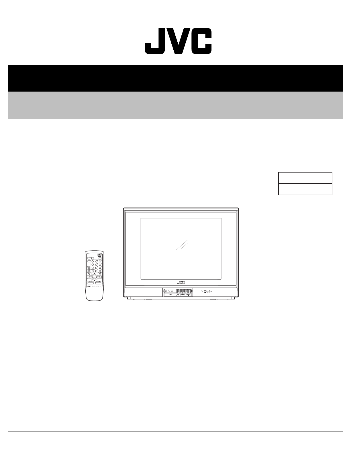
SERVICE MANUAL
COLOUR TELEVISION
YA41620068
AV-2106BE, AV-21B16/L,
AV-21BMG6B
TABLE OF CONTENTS
1 PRECAUTION. . . . . . . . . . . . . . . . . . . . . . . . . . . . . . . . . . . . . . . . . . . . . . . . . . . . . . . . . . . . . . . . . . . . . . . . . 1-3
2 SPECIFIC SERVICE INSTRUCTIONS . . . . . . . . . . . . . . . . . . . . . . . . . . . . . . . . . . . . . . . . . . . . . . . . . . . . . . 1-4
3 DISASSEMBLY . . . . . . . . . . . . . . . . . . . . . . . . . . . . . . . . . . . . . . . . . . . . . . . . . . . . . . . . . . . . . . . . . . . . . . . 1-5
4 ADJUSTMENT . . . . . . . . . . . . . . . . . . . . . . . . . . . . . . . . . . . . . . . . . . . . . . . . . . . . . . . . . . . . . . . . . . . . . . . 1-11
5 TROUBLESHOOTING . . . . . . . . . . . . . . . . . . . . . . . . . . . . . . . . . . . . . . . . . . . . . . . . . . . . . . . . . . . . . . . . . 1-28
/G, AV-21BMG6/G
BASIC CHASSIS
CG4
COPYRIGHT © 2006 Victor Company of Japan, Limited
No.YA416
2006/8
Page 2
SPECIFICATION
Items Contents
AV-2106BE AV-21B16/L AV-21BMG6B/G AV-21BMG6/G
Dimensions (W × H × D) 59.8 cm × 47.6 cm × 47.7 cm
Mass 22 kg
TV RF System B/G, I, D/K B/G, I, D/K, M
Colour System PAL
SECAM
Receiving
Frequency
Intermediate Frequency VIF 38.0 MHz (B/G, I, D/K)
Colour Sub Carrier PAL
Power Input AC110 V to AC240 V, 50 Hz / 60 Hz
Power Consumption 100 W (Max) / 65 W(Avg)
Picture Tube Visible size: 52.3 cm measured diagonally
High Voltage 26.5 kV±1.5kV (at zero beam current)
Speaker 5 cm × 9 cm, Oval type × 2
Audio Power Output 3 W (monaural)
Aerial Input Terminal 75 Ω unbalanced, coaxial
Input Terminal
[Front / Rear]
Output Terminal
[Rear]
Headphone Jack 3.5 mm mini jack × 1
Remote Control Unit RM-C360GY (Battery size : AA / R6 / UM-3 × 2)
VHF Low
VHF High
SECAM
46.25 MHz to 140.25 MHz
147.25 MHz to 423.25 MHz
UHF
431.25 MHz to 863.25 MHz
CATV
Mid (X to Z+2, S1 to S10) / Super (S11 to S20) / Hyper (S21 to S41) bands
SIF 32.5 MHz (5.5 MHz: B/G)
32MHz (6.0 MHz: I)
31.5MHz (6.5 MHz: D/K)
4.43 MHz
4.40625 MHz / 4.25 MHz
NTSC
---
( H : 41.6 cm × V : 31.5 cm)
Video
1 V(p-p), 75 Ω, RCA pin jack × 2
Audio
500 mV(rms) (-4 dBs), High impedance, RCA pin jack × 2
Video
1 V(p-p), 75Ω, RCA pin jack × 1
Audio
500 mV(rms) (-4 dBs), Low impedance, RCA pin jack × 1
PAL
SECAM
NTSC3.58/NTSC4.43
32.5 MHz (5.5 MHz: B/G)
32MHz (6.0 MHz: I)
31.5MHz (6.5 MHz: D/K)
33.5MHz (4.5MHz: M)
4.43 MHz
4.40625 MHz / 4.25 MHz
3.58 MHz / 4.43 MHz
Design and specifications are subject to change without notice.
1-2 (No.YA416)
Page 3

SECTION 1
PRECAUTION
1.1 SAFETY PRECAUTIONS
(1) The design of this product contains special hardware,
many circuits and components specially for safety
purposes. For continued protection, no changes should be
made to the original design unless authorized in writing by
the manufacturer. Replacement parts must be identical to
those used in the original circuits. Service should be
performed by qualified personnel only.
(2) Alterations of the design or circuitry of the products should
not be made. Any design alterations or additions will void
the manufacturer's warranty and will further relieve the
manufacturer of responsibility for personal injury or
property damage resulting therefrom.
(3) Many electrical and mechanical parts in the products have
special safety-related characteristics. These
characteristics are often not evident from visual inspection
nor can the protection afforded by them necessarily be
obtained by using replacement components rated for
higher voltage, wattage, etc. Replacement parts which
have these special safety characteristics are identified in
the parts list of Service manual. Electrical components
having such features are identified by shading on the
schematics and by ( ) on the parts list in Service
manual. The use of a substitute replacement which does
not have the same safety characteristics as the
recommended replacement part shown in the parts list of
Service manual may cause shock, fire, or other hazards.
(4) Don't short between the LIVE side ground and
ISOLATED (NEUTRAL) side ground or EARTH side
ground when repairing.
Some model's power circuit is partly different in the GND.
The difference of the GND is shown by the LIVE : ( ) side
GND, the ISOLATED (NEUTRAL) : ( ) side GND and
EARTH : ( ) side GND.
Don't short between the LIVE side GND and ISOLATED
(NEUTRAL) side GND or EARTH side GND and never
measure the LIVE side GND and ISOLATED (NEUTRAL)
side GND or EARTH side GND at the same time with a
measuring apparatus (oscilloscope etc.). If above note will
not be kept, a fuse or any parts will be broken.
(5) If any repair has been made to the chassis, it is
recommended that the B1 setting should be checked or
adjusted (See ADJUSTMENT OF B1 POWER SUPPLY).
(6) The high voltage applied to the picture tube must conform
with that specified in Service manual. Excessive high
voltage can cause an increase in X-Ray emission, arcing
and possible component damage, therefore operation
under excessive high voltage conditions should be kept to
a minimum, or should be prevented. If severe arcing
occurs, remove the AC power immediately and determine
the cause by visual inspection (incorrect installation,
cracked or melted high voltage harness, poor soldering,
etc.). To maintain the proper minimum level of soft X-Ray
emission, components in the high voltage circuitry
including the picture tube must be the exact replacements
or alternatives approved by the manufacturer of the
complete product.
(7) Do not check high voltage by drawing an arc. Use a high
voltage meter or a high voltage probe with a VTVM.
Discharge the picture tube before attempting meter
connection, by connecting a clip lead to the ground frame
and connecting the other end of the lead through a 10kΩ
2W resistor to the anode button.
(8) When service is required, observe the original lead dress.
Extra precaution should be given to assure correct lead
dress in the high voltage circuit area. Where a short circuit
has occurred, those components that indicate evidence of
overheating should be replaced. Always use the
manufacturer's replacement components.
(9) Isolation Check (Safety for Electrical Shock Hazard)
After re-assembling the product, always perform an
isolation check on the exposed metal parts of the cabinet
(antenna terminals, video/audio input and output terminals,
Control knobs, metal cabinet, screw heads, earphone jack,
control shafts, etc.) to be sure the product is safe to operate
without danger of electrical shock.
a) Dielectric Strength Test
The isolation between the AC primary circuit and all metal
parts exposed to the user, particularly any exposed metal
part having a return path to the chassis should withstand a
voltage of 3000V AC (r.m.s.) for a period of one second. (.
. . . Withstand a voltage of 1100V AC (r.m.s.) to an
appliance rated up to 120V, and 3000V AC (r.m.s.) to an
appliance rated 200V or more, for a period of one second.)
This method of test requires a test equipment not generally
found in the service trade.
b) Leakage Current Check
Plug the AC line cord directly into the AC outlet (do not use
a line isolation transformer during this check.). Using a
"Leakage Current Tester", measure the leakage current
from each exposed metal part of the cabinet, particularly
any exposed metal part having a return path to the chassis,
to a known good earth ground (water pipe, etc.). Any
leakage current must not exceed 0.5mA AC (r.m.s.).
However, in tropical area, this must not exceed 0.2mA AC
(r.m.s.).
Alternate Check Method
Plug the AC line cord directly into the AC outlet (do not
use a line isolation transformer during this check.). Use
an AC voltmeter having 1000Ω per volt or more
sensitivity in the following manner. Connect a 1500Ω
10W resistor paralleled by a 0.15µF AC-type capacitor
between an exposed metal part and a known good earth
ground (water pipe, etc.). Measure the AC voltage
across the resistor with the AC voltmeter. Move the
resistor connection to each exposed metal part,
particularly any exposed metal part having a return path
to the chassis, and measure the AC voltage across the
resistor. Now, reverse the plug in the AC outlet and
repeat each measurement. Any voltage measured must
not exceed 0.75V AC (r.m.s.). This corresponds to
0.5mA AC (r.m.s.).
However, in tropical area, this must not exceed 0.3V AC
(r.m.s.). This corresponds to 0.2mA AC (r.m.s.).
AC VOLTMETER
(HAVING 1000 /V,
OR MORE SENSITIVITY)
0.15 F AC-TYPE
PLACE THIS PROBE
1500 10W
GOOD EARTH GROUND
ON EACH EXPOSED
ME TAL PAR T
(No.YA416)1-3
Page 4
SECTION 2
SPECIFIC SERVICE INSTRUCTIONS
2.1 FEATURES
PICTURE MODE
This function can adjust the picture settings automatically.
There are BRIGHT, STANDARD and SOFT in the PICTURE
MODE.
RETURN +
This function can set a channel you frequently view to the
Return Channel and you can view that channel at any time with
one-touch.
2.2 MAIN DIFFERENCE LIST
ITEM AV-2106BE AV-21B16/L AV-21BMG6B/G AV-21BMG6/G
OSD Language Eng, Rus, Ukr Chi Malay Ind Eng, Ara, Per, Rus ←
MAIN PWB SCG-1549A-H2 SCG-1547A-H2 SCG-1548A-H2 ←
TV RF System B/G, I, D/K ← B/G, I, D/K, M ←
2.3 TECHNINAL INFORMATION
2.3.1 MAIN MI-COM (CPU) PIN FUNCTION
Pin
No.
Pin name I/O Function
1 REMOCON I Remote control 22 PROTECT I Low B protect detection [Detect: H]
2 SDA2 I/O Data for Inter IC control (For main memory) 23 P_ON/OFF I Main power control [ON : H]
3 SCL2 O Clock for Inter IC contorl (For main memory) 24 LOCK - Not used
4 BUS_FREE - Not used 25 3.58/OTH - Not used
5 NC - Not used 26 4.5/OTH - Not used
6 KEY1 I Key scan for front key (Menu CH -/+) 27 H_SYNC I Horizontal sync
7 KEY2 I Key scan for front key (Vol -/+) 28 I/II - Not used
8 ECO IN - Not used 29 OSD_Ys O Ys (blanking) for OSD
9 AFT I AFT voltage for tuner 30 OSD_B O Blue for OSD
10 LED[POW] - Not used 31 OSD_G O Green for OSD
11 LED[TIM] O Liting for timer [Liting : H] 32 OSD_R O Red for OSD
12 GND - GND 33 NC - Not used
13 NC - Not used 34 RST I CPU reset [Reset:L]
14 NC - Not used 35 V_SYNC I Vertical sync
15 TV/V - Not used 36 TCLOCK - Not used
16 TEXT RESET - Not used 37 SDA1 I/O Data for Inter IC control (For generally)
17 ACL ON/OFF - Not used 38 SCL1 O Clock for Inter IC contorl (For generally)
18 VOL O Volume control 39 VDD I 3.3V
19 A_MUTE O Aodio muting [Muting : H] 40 OSC1 I System clock oscillation (4MHz)
20 NC - Not used 41 OSC2 O System clock oscillation (4MHz)
21 TEXT/OTH - Not used 42 VSS - GND
CHILD LOCK
Use this function to prevent children from operating the TV
without parental consent.
VNR
This function can reduce the picture noise.
Pin
No.
Pin name I/O Function
1-4 (No.YA416)
Page 5

SECTION 3
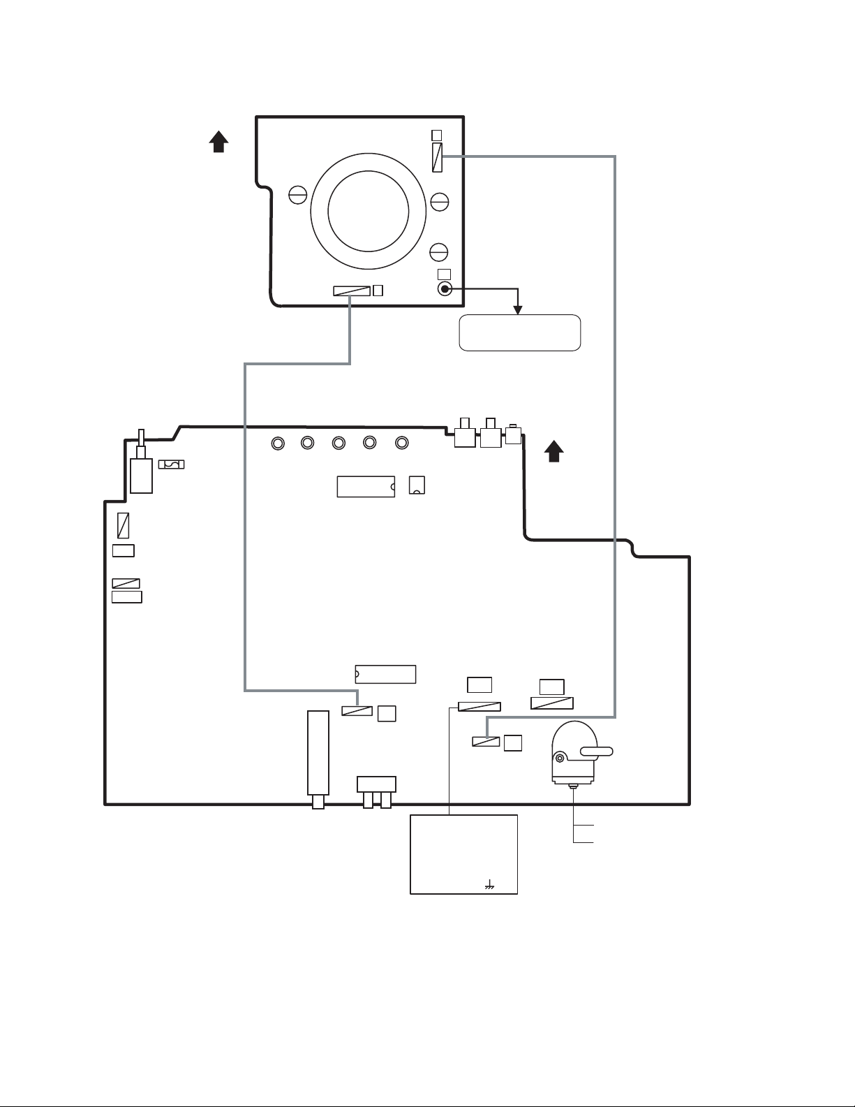
DISASSEMBLY
3.1 DISASSEMBLY PROCEDURE
3.1.1 REMOVING THE REAR COVER
• Unplug the power cord.
(1) Remove the 6 screws [A], 1 screw [B] and 1 screw [C] as
shown in Fig.1.
(2) Withdraw the REAR COVER toward you.
CAUTION:
When reinstalling the rear cover, carefully push it inward after
inserting the MAIN PWB into the REAR COVER groove.
3.1.2 REMOVING THE MAIN PW BOARD
• Remove the REAR COVER.
(1) Slightly raise the both sides of the MAIN PWB by hand.
(2) Withdraw the MAIN PWB backward.
(If necessary, take off the wire clamp and connectors, etc.)
3.1.3 REMOVING THE SPEAKER
• Remove the REAR COVER.
(1) Remove the 2 screws [D] as shown in Fig.1.
(2) Follow the same steps when removing the other hand
SPEAKER.
3.1.4 CHECKING THE MAIN PW BOARD
• To check the back side of the MAIN PWB.
(1) Pull out the MAIN PWB. (Refer to REMOVING THE MAIN
PW BOARD).
(2) Erect the MAIN PWB vertically so that you can easily check
its back side.
CAUTIONS:
• Before turning on power, make sure that the CRT earth wire
and other connectors are properly connected.
• When repairing, connect the DEG. COIL to the DEG.
connector on the MAIN PWB.
3.1.5 WIRE CLAMPING AND CABLE TYING
(1) Be sure to clamp the wire.
(2) Never remove the cable tie used for tying the wires
together.
Should it be inadvertently removed, be sure to tie the wires
with a new cable tie.
(No.YA416)1-5
Page 6
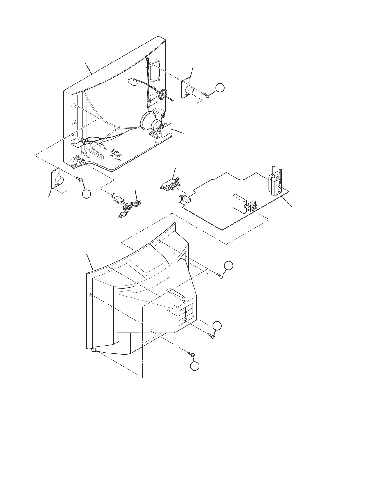
SPEAKER
FRONT CABINET
D
SPEAKER
D
CRT SOCKET PWB
(Within MAIN PWB)
FRONT LED PWB
(Within MAIN PWB)
POWER CORD
MAIN PWB
REAR COVER
A
C
B
Fig.1
1-6 (No.YA416)
Page 7
3.2 MEMORY IC REPLACEMENT
• This model uses the memory IC.
• This memory IC stores data for proper operation of the video and drive circuits.
• When replacing, be sure to use an IC containing this (initial value) data.
3.2.1 MEMORY IC REPLACEMENT PROCEDURE
1. Power off
Switch off the power and disconnect the power plug from the
AC outlet.
2. Replace the memory IC
Be sure to use the memory IC written with the initial setting
values.
3. Power on
Connect the power plug to the AC outlet and switch on the
power.
4. System constant check and setting
• It must not adjust without adjustment signals.
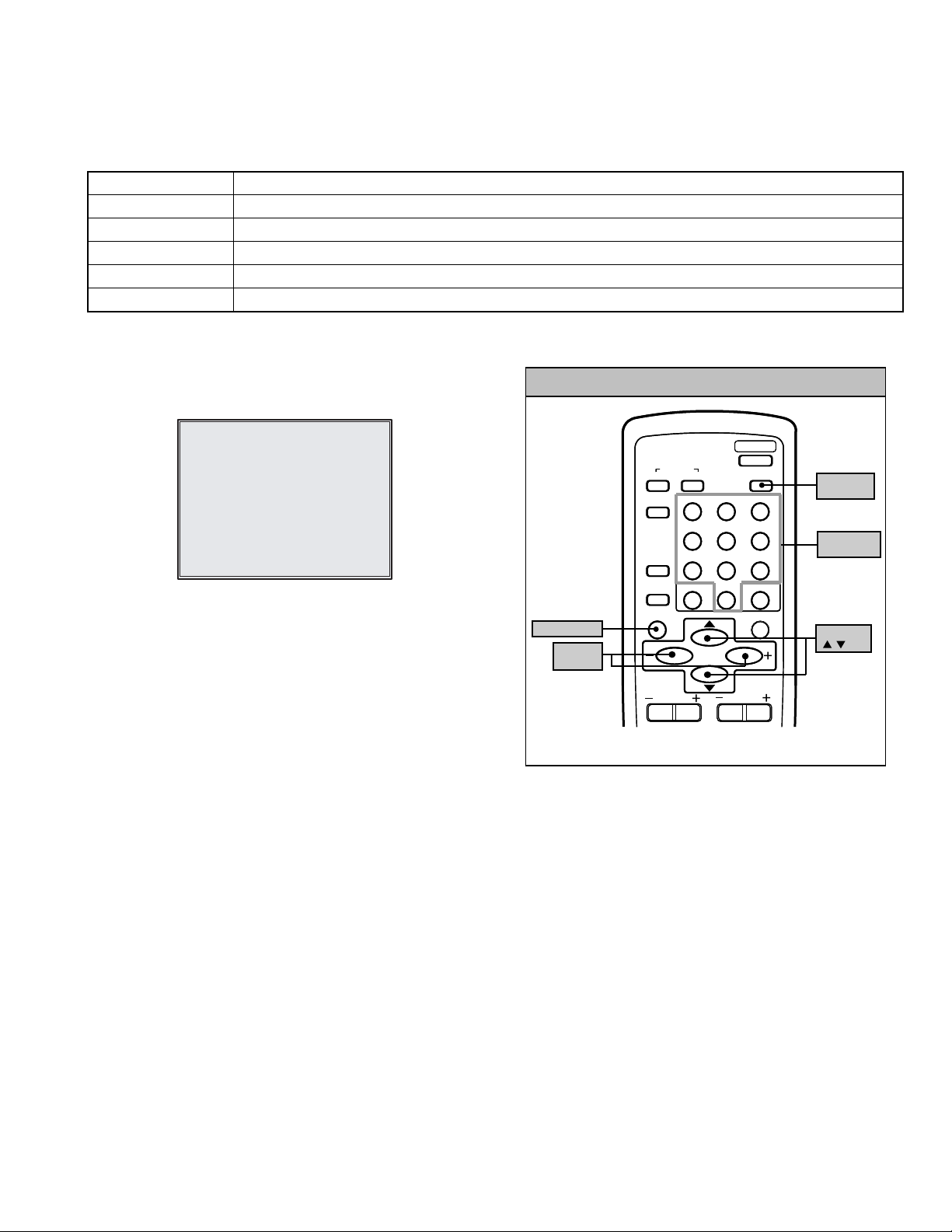
(1) Press the [DISPLAY] key and the [PICTURE MODE]
key of the REMOTE CONTROL UNIT simultaneously.
(2) The SERVICE MENU screen of Fig. 1 will be displayed.
(3) While the SERVICE MENU is displayed, again press the
[DISPLAY] key and [PICTURE MODE] key
simultaneously, and the SYSTEM CONSTANT SET
screen of Fig. 2 will be displayed.
(4) Check the setting values of the SYSTEM CONSTANT
SETTING. If the value is different, select the setting item
with the [MENU /] key, and set the correct value with
the [MENU - / +] key.
(5) Press the [DISPLAY] key twice, and return to the normal
screen.
5. Receiving channel setting
Refer to the OPERATING INSTRUCTIONS and set the
receive channels (Channels Preset) as described.
6. User settings
Check the user setting items according to the given in page
later.
Where these do not agree, refer to the OPERATING
INSTRUCTIONS and set the items as described.
7. SERVICE MENU setting
Verify what to set in the SERVICE MENU, and set whatever is
necessary (Fig.1).
Refer to the SERVICE ADJUSTMENT for setting.
SERVICE MENU
1.IF 2.V/C
3.DEF 4.VSM PRESET
5.PRESET
6.SETUP TOUR OFF
1-6 : SELECT DISP : EXIT
************ **.***
*** ** **** ***
Fig.1
SYSTEM CONSTANT- I
SYSTEM CONSTANT SET 1
COLOUR : TRIPLE
BILINGUAL : NO
TUNER : MU
ECO SENSOR
LANGUAGE : E/R/U
: SELECT
/
- / + : OPERATE DISP : EXIT
SYSTEM CONSTANT- II
SYSTEM CONSTANT SET 2
B/B SOUND : OFF
LOCK : 180
COLOUR AUTO
QSS
ALC : NO
TEXT RATE
: SEL - / + : OPE DISP : EXIT
/
SYSTEM CONSTANT- III
: NO
: NO
: MINT
: 20
KEY ASSIGNMENT OF REMOTE CONTROL UNIT
POWER
SOUND
123
456
789
RETURN+
0
MENU
MENU
VOLUME
PICTURE
MODE
MUTING
PICTURE
MODE key
NUMBERS
key
-/--
MENU
/ key
DISPLAY key
MENU
- / + key
COLOUR
TV/VIDEO
OFF
TIMER
CHANNEL
SCAN
DISPLAY
CHANNEL
SYSTEM
SYSTEM CONSTANT SET 3
AMP TUNER : NO
VNR
TEXT TABLE : CYL
VOLUME PWM : POS
/
: SEL - / + : OPE DISP : EXIT
: YES
Fig.2
(No.YA416)1-7
Page 8
3.2.2 SETTINGS OF FACTORY SHIPMENT
3.2.2.1 BUTTON OPERATION
Setting item Setting position
POWER Off
CHANNEL PR1
VOLUME 10
3.2.2.2 REMOTE CONTROL DIRECT OPERATION
Setting item Setting position
CHANNEL PR1
VOLUME 10
TV/VIDEO TV
PICTURE MODE BRIGHT
COLOUR SYSTEM PAL
SOUND SYSTEM B/G
3.2.2.3 REMOTE CONTROL MENU OPERATION
(1) MENU-1
Setting item Setting position
INPUT TV
ON TIMER PR1 0:00
VNR OFF
3.2.3 SYSTEM CONSTANT SETTING
Setting item
COLOUR TRIPLE ← MULTI ←
BILINGUAL NO ←←←
TUNER MU ←←←
ECO SENSOR NO ←←←
LANGUAGE E/R/U E/C/M/I E/A/P/R ←
B/B SOUND OFF ←←←
LOCK 180 ←←←
COLOUR AUTO NO ← YES ←
QSS MINT ←←←
ALC NO ←←←
TEXT RATE 20 ←←←
AMP TUNER NO ←←←
VNR YES ←←←
TEXT TABLE CYL ←←←
VOLUME PWM POS ←←←
AV-2106BE
Setting value
AV-21B16/L
AV-21BMG6B/G
AV-21BMG6/G
(2) MENU-2
Setting item Setting position
AUTO SHUTOFF OFF
CHILD LOCK OFF
BLUE BACK OFF
(3) MENU-3
Setting item Setting position
SETUP TOUR ON
LANGUAGE ENGLISH
(4) MENU-4
Setting item
TINT 15 15 15
COLOUR
BRIGHT 15 15 15
CONT. 30 15 11
SHARP 151512
BRIGHT STANDARD SOFT
15 15 15
Setting position
1-8 (No.YA416)
Page 9
3.2.4 SERVICE MENU SETTING ITEMS
Setting item Setting value Setting item Setting value
2. V/C 1.CUT OFF
2.DRIVE
3.BRIGHT
4.CONT.
5.COLOUR
6.TINT
7.SECAM BL ADJUST
8.SHARP [Do not adjust]
9.AMP T. SHARP [Do not adjust]
3. DEFLECTION 1. VER. POSITION
2. HOR. POSITION
3. VER. HEIGHT
4. VER. LINEARITY
5. VER. SCURVE
6. HOR. VCO ADJUST [Do not adjust]
4.VSM PRESET TINT
COLOUR
BRIGHT
CONT.
SHARP
5. PRESET
[Do not adjust]
Colour System 1. C-TRAP FIX
2. SHARP PEAK
3. ABL
4. GAMMA
5. Y. DELAY TIME
6. BLACK EXP START
7. C-BPF
8. CW / SCP
9. VIF DET LEVEL
11. IF AGC MIN
12. VIF AGC
13. VIF PMOD
19. VNR
20. RGB LIM
21. RGB LIMIT LEVEL
23. TEXT H. POSITION
24. READ DATA
Sound System 10. SIF DET LEVEL
14. SIF BPF BW ADJUST
15. SIF TRAP F0 ADJUST
16. SIF TRAP F0 ADJUST 2
17. SIF -TRAP
18. SIF -BPF
22. SIF SW
3.2.5 REPLACEMENT OF IC301 (IF V/C DECODER)
• For the IC301(IF V/C DECODER) of this model, all data are written in the micro-computer. So, write the data in the micro-
computer in accordance with the following procedures before starting adjustment.
PROCEDURES
(1) Turn the POWER OFF.
(2) Replace the IC301 with a new one.
(3) While pressing [MENU] button and [VOL+] button ON the FRONT CABINET simultaneously, turn the POWER ON. When the
POWER is turned ON, the data is written in the micro-computer immediately.
LOCATIONS OF FRONT PANEL BUTTONS
(No.YA416)1-9
Page 10
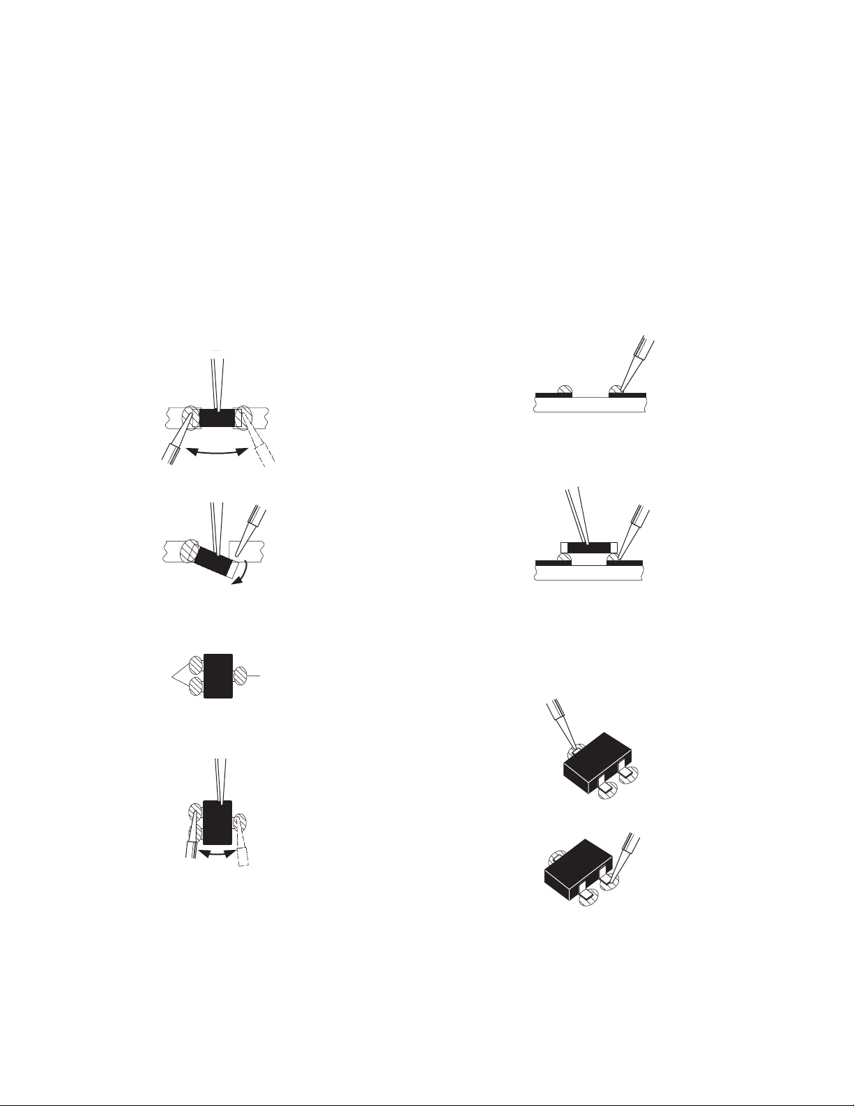
3.3 REPLACEMENT OF CHIP COMPONENT
3.3.1 CAUTIONS
(1) Avoid heating for more than 3 seconds.
(2) Do not rub the electrodes and the resist parts of the pattern.
(3) When removing a chip part, melt the solder adequately.
(4) Do not reuse a chip part after removing it.
3.3.2 SOLDERING IRON
(1) Use a high insulation soldering iron with a thin pointed end of it.
(2) A 30w soldering iron is recommended for easily removing parts.
3.3.3 REPLACEMENT STEPS
1. How to remove Chip parts
2. How to install Chip parts
[Resistors, capacitors, etc.]
(1) As shown in the figure, push the part with tweezers and
alternately melt the solder at each end.
(2) Shift with the tweezers and remove the chip part.
[Transistors, diodes, variable resistors, etc.]
(1) Apply extra solder to each lead.
SOLDER
SOLDER
[Resistors, capacitors, etc.]
(1) Apply solder to the pattern as indicated in the figure.
(2) Grasp the chip part with tweezers and place it on the
solder. Then heat and melt the solder at both ends of the
chip part.
[Transistors, diodes, variable resistors, etc.]
(1) Apply solder to the pattern as indicated in the figure.
(2) Grasp the chip part with tweezers and place it on the
solder.
(3) First solder lead A as indicated in the figure.
(2) As shown in the figure, push the part with tweezers and
alternately melt the solder at each lead. Shift and remove
the chip part.
NOTE :
After removing the part, remove remaining solder from the
pattern.
1-10 (No.YA416)
A
B
C
(4) Then solder leads B and C.
A
B
C
Page 11
SECTION 4
ADJUSTMENT
4.1 ADJUSTMENT PREPARATION
(1) There are 2 ways of adjusting this TV : One is with the
REMOTE CONTROL UNIT and the other is the
conventional method using adjustment parts and
components.
(2) The adjustment using the REMOTE CONTROL UNIT is
made on the basis of the initial setting values. The
setting values which adjust the screen to the optimum
condition can be different from the initial setting
values.
(3) Make sure that connection is correctly made AC to AC
power source.
(4) Turn on the power of the TV and measuring instruments for
warming up for at least 30 minutes before starting
adjustments.
(5) If the receive or input signal is not specified, use the most
appropriate signal for adjustment.
(6) Never touch the parts (such as variable resistors,
transformers and condensers) not shown in the adjustment
items of this service adjustment.
4.2 PRESET SETTING BEFORE ADJUSTMENT
Unless otherwise specified in the adjustment items, preset the
following functions with the REMOTE CONTROL UNIT.
Item Preset value
PICTURE MODE BRIGHT
TINT / COLOUR / BRIGHT / CONT. / SHARP Centre
VNR OFF
BLUE BACK OFF
OFF TIMER OFF
AUTO SHUT OFF OFF
4.3 MEASURING INSTRUMENT AND FIXTURES
(1) DC voltmeter (or digital voltmeter)
(2) Oscilloscope
(3) Signal generator
(Pattern generator : PAL / SECAM / NTSC)
(4) Remote control unit
4.4 ADJUSTMENT ITEMS
CHECK ITEM
• B1 VOLTAGE check
TUNER / IF CIRCUIT
• IF VCO adjustment
• DELAY POINT adjustment
FOCUS
• FOCUS adjustment
DEFLECTION CIRCUIT
• V.HEIGHT / V.POSITION adjustment
• H. POSITION adjustment
• V.LINEARITY / V.S-CURVE adjustment
VIDEO CIRCUIT
• WHITE BALANCE adjustment
• SUB BRIGHT adjustment
• SUB CONTRAST adjustment
• SUB COLOUR adjustment
• SUB TINT adjustment
• SECAM BALACK OFFSET adjustment
VSM PRESET SETTING
• VSM PRESET setting
(No.YA416)1-11
Page 12
4.5 ADJUSTMENT LOCATIONS
F901
TOP
CRT SOCKET PWB
TP-47G/R
T
IC701
(SOLDER SIDE)
U
TP-47B
TP-E
E1
CRT EARTH WIRE
(BRAIDED ASS'Y)
FRONT
IC702
MEMORY IC
PW
DEG
MAIN PWB
TU001
IC301
T
1Pin TP-91(B1)
2Pin NC
3Pin X-ray1
4Pin X-ray2
5Pin TP-E( )
S1
51
U
HV
HVT
UPPER:FOCUS
LOWER:SCREEN
1-12 (No.YA416)
Page 13
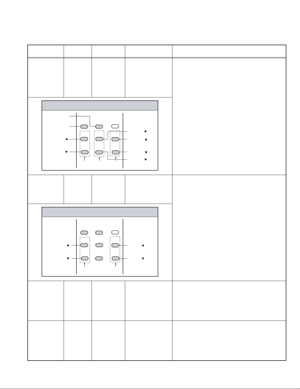
4.6 BASIC OPERATION OF SERVICE MENU
4.6.1 TOOL OF SERVICE MENU OPERATION
Operate the SERVICE MENU with the REMOTE CONTROL UNIT.
4.6.2 SERVICE MENU ITEMS
With the SERVICE MENU, various adjustments can be made, and they are broadly classified in the following items of settings.
1.IF Adjustment of the IF circuits.
2.V/C Adjustment of the VIDEO circuit.
3.DEF Adjustment of the DEFLECTION circuit.
4.VSM PRESET Adjustment of the initial setting values of VSM condition as STANDARD, SOFT and BRIGHT.
5.PRESET Adjustment of the RF circuit [Do not adjust].
6.SETUP TOUR It should be able to select mode (LANGUAGE and AUTO CH PRESET) [Should be OFF].
4.6.3 HOW TO ENTER THE SERVICE MENU
Press the [DISPLAY] key and the [PICTURE MODE] key of
the REMOTE CONTROL UNIT simultaneously. Then enter the
SERVICE MODE SELECT KEY
SERVICE MENU mode as shown in Fig.1.
POWER
SERVICE MENU
1.IF 2.V/C
3.DEF 4.VSM PRESET
5.PRESET
6.SETUP TOUR OFF
1-6 : SELECT DISP : EXIT
************ **.***
*** ** **** ***
Fig.1
4.6.4 HOW TO STORE OF SETTING VALUE
The setting value will be stored automatically when release the
REMOTE CONTROL UNIT keys
DISPLAY key
MENU
- / + key
SYSTEM
COLOUR
TV/VIDEO
OFF
TIMER
CHANNEL
SCAN
DISPLAY
CHANNEL
SOUND
RETURN+
MENU
MENU
PICTURE
123
456
789
0-/
MUTING
VOLUME
MODE
PICTURE
MODE key
NUMBERS
key
--
MENU
/ key
4.6.5 HOW TO EXIT THE SERVICE MENU
When complete the adjustment work, press the [DISPLAY]
key to return to the SERVICE MENU. And then press the
[DISPLAY] key again, return to the normal screen.
4.6.6 SELECTION OF SUB MENU SCREEN
Press one of [1] to [5] keys of the REMOTE CONTROL UNIT
and select the SUB MENU SCREEN form the SERVICE
MENU.
(No.YA416)1-13
Page 14

4.6.7 METHOD OF SETTING
1. IF
[1. VCO]
(1) [1] key Select 1. IF.
(2) [1] key Select 1. VCO.
(3) [MENU /] keys Select setting items.
(4) [MENU - / +] keys Adjust the values of the items.
(5) [DISPLAY] key As you press this key twice, you will return to the SERVICE MENU.
[2. DELAY POINT]
(1) [1] key Select 1. IF.
(2) [2] key Select 2. DELAY POINT.
(3) [MENU - / +] keys Set (adjust) the setting values of the setting items.
(4) [DISPLAY] key When this is pressed twice, you will return to the SERVICE MENU.
NOTE:
When the setting value has been changed, the new value will be stored in memory immediately.
2. V/C, 3. DEF and 4. VSM PRESET
(1) [2] to [4] keys Select one from 2. V/C, 3. DEF and 4. VSM PRESET.
(2) [MENU /] keys Select setting items.
(3) [MENU - / +] keys Adjust the values of the items.
(4) [DISPLAY] key When this is pressed, return to the SERVICE MENU.
NOTE:
When the setting value has been changed, the new value will be stored in memory immediately.
5. PRESET (Do not adjust)
6. SETUP TOUR
(1) By pressing the [6] key, you can change the ON or OFF [should be OFF].
Should be OFF:
If it is ON, when you turn off the power and turn on a power again, the JVC’s logo will be shown
about 15 seconds automatically, and the SETUP TOUR starts.
(2) [MENU - / +] keys Select Language.
(3) [MENU ] key Auto Search.
1-14 (No.YA416)
Page 15
4.6.8 SERVICE MENU FLOW CHART
************ **.***
SERVICE MENU
1. IF
SERVICE MENU
1.IF 2.V/C
3.DEF 4.VSM PRESET
5.PRESET
6.SETUP TOUR OFF
1-6 : SELECT DISP : EXIT
************ **.***
6. SETUP TOUR OFF
*** ** **** ***
ON / OFF
(By pressing [6] key)
IF
1. VCO
2. DELAY POINT
1-2 : SELECT DISP : EXIT
2. V/C
V/C PAL
1. CUTOFF
(G)
(B)
50Hz
/ : SELECT
- / + : OPERATE DISP : EXIT
(R)
* **
* **
* **
3. DEF
VCO (CW)
TOO HIGH
ABOVE REFERENCE
JUST REFERENCE
BELOW REFERENCE
TOO LOW
AFT ADJUST
VCO ADJUST
FINE
DISP : EXIT
DELAY POINT UHF
AGC TAKE-OVER
- / + : OPERATE DISP : EXIT
***.**
MHz
*** (**
*** (**
**
)
)
DEF PAL
1. VER. POSITION
50Hz
/ : SELECT
- / + : OPERATE DISP : EXIT
**
4. VSM PRESET
BRIGHT
TINT
COLOUR
BRIGHT
CONT.
SHARP
/ : SELECT
- / + : OPERATE DISP : EXIT
**
**
**
**
**
5. PRESET
PRESET PAL
1. C-TRAP FIX
*
50Hz B/G
/ : SELECT
- / + : OPERATE DISP : EXIT
(No.YA416)1-15
Page 16
4.7 INITIAL SETTING VALUE OF SERVICE MENU
• Adjustment of the SERVICE MENU is made on the basis of the initial setting values ; however, the new setting values which
set the screen in its optimum condition may differ from the initial setting.
• Do not change the initial Setting Values of the Setting (Adjustment) items not listed in "ADJUSTMENT PROCEDURE".
[2. V/C] [AV-2106BE, AV-21B16/L]
Setting item Variable range
1.CUT OFF RED -128 - +127 -50 -50 -50 -50
GREEN -128 - +127 -50 -50 -50 -50
BLUE -128 - +127 -50 (Fixed) -50 (Fixed) -50 (Fixed) -50 (Fixed)
2.DRIVE RED -128 - +127 +0 +0 +0 +0
BLUE -128 - +127 +0 +0 +0 +0
3.BRIGHT -128 - +127 +0 +0 +0 +0
4.CONT. -63 - +63+0+0+0+0
5.COLOUR -63 - +63 +0 +0 +0 +1 (Fixed)
6.TINT TV -63 - +63 --- --- --- ---
VIDEO -63 - +63 --- --- +0 -2 (Fixed)
7.SECAM BL ADJUST -31 - +31 +0 +0 +0 +0
8.SHARP
(Do not adjust)
[AV-21BMG6B/G, AV-21BMG6/G]
1.CUT OFF RED -128 - +127 -50 -50 -50 -50
2.DRIVE RED -128 - +127 +0 +0 +0 +0
3.BRIGHT -128 - +127 +0 +0 +0 +0
4.CONT. -63 - +63+0+0+0+0
5.COLOUR -63 - +63 +0 +0 +0 -5 (Fixed)
6.TINT TV -63 - +63 --- --- +0 (Fixed) +0 (Fixed)
7.SECAM BL ADJUST -31 - +31 +0 +0 +0 +0
8.SHARP
(Do not adjust)
TV -31 - +31 +2 (Fixed) +2 (Fixed) +2 (Fixed) +2 (Fixed)
VIDEO -31 - +31 +15 (Fixed) +15 (Fixed) +15 (Fixed) +15 (Fixed)
Setting item Variable range
GREEN -128 - +127 -50 (Fixed) -50 (Fixed) -50 (Fixed) -50 (Fixed)
BLUE -128 - +127 -50 -50 -50 -50
BLUE -128 - +127 +0 +0 +0 +0
VIDEO -63 - +63 --- --- +7 (Fixed) +3 (Fixed)
TV -31 - +31 +2 (Fixed) +2 (Fixed) +2 (Fixed) +2 (Fixed)
VIDEO -31 - +31 +15 (Fixed) +15 (Fixed) +15 (Fixed) +15 (Fixed)
PAL SECAM NTSC 3.58 NTSC 4.43
PAL SECAM NTSC 3.58 NTSC 4.43
Initial setting value
Initial setting value
1-16 (No.YA416)
Page 17
[3. DEFLECTION]
Setting item Variable range
1. VER. POSITION -4 - +3 -1 -3
2. HOR. POSITION -16 - +15 +3 +3
3. VER. HEIGHT -64 - +63 -35 +1
4. VER. LINEARITY -32 - +31 +15 -1
5. VER. SCURVE -32 - +31 -32 +0
6. HOR. VCO ADJUST
[4.VSM PRESET]
Setting item Variable range
TINT 0 - 30 15 15 15
COLOUR 0 - 30 15 15 15
BRIGHT 0 - 30 15 15 15
CONT. 0 - 30 30 15 11
SHARP 0 - 30 15 15 12
[Do not adjust]
-63 - +63 +0 +0
Initial setting value
fv : 50Hz fv : 60Hz
Initial setting value
BRIGHT STANDARD SOFT
(No.YA416)1-17
Page 18
[5. PRESET]
The items in the following table, it is no requirement for adjustment.If values had changed by the miss operation, set the
initial setting values in the following table.
z COLOUR SYSTEM (Do not adjust)
[AV-2106BE, AV-21B16/L]
Setting item Variable range
1. C TRAP FIX 0 - 1 1 1 1 1
2. SHARP PEAK 0 - 1 0 0 --- ---
3. ABL 0 - 1 1 1 1 1
4. GAMMA 0 - 1 0 0 0 0
5. Y. DELAY TIME TV 0 - 3 0 2 --- ---
VIDEO 0 - 3 0 2 --- ---
6. BLACK EXP START
7. C-BPF TV 0 - 1 1 1 --- ----
VIDEO 0 - 1 1 1 --- ---
8. CW / SCP 0 - 1 0 0 0 0
9. VIF DET LEVEL -63 - +63 0 0 0 0
11. IF AGC MIN 0 - 1 0 0 0 0
12. VIF AGC 0 - 1 0 0 0 0
13. VIF PMOD 0 - 1 0 0 0 0
19. VNR 0 - 63 15 15 15 15
20. RGB LIM 0 - 1 1 1 1 1
21. RGB LIMIT LEVEL
23. TEXT H. POSITION
24. READ DATA --- --- --- --- ---
0 - 3+3+3+3+3
0 - 72222
-16 - +15-3-3-3-3
PAL SECAM NTSC 3.58 NTSC 4.43
Initial setting value (Fixed value)
1-18 (No.YA416)
Page 19
[AV-21BMG6B/G, AV-21BMG6/G]
Setting item Variable range
1. C TRAP FIX 0 - 1 1 1 1 1
2. SHARP PEAK 0 - 1 0 0 0 0
3. ABL 0 - 11111
4. GAMMA 0 - 1 0 0 0 0
5. Y. DELAY TIME TV 0 - 3 0 2 0 1
VIDEO0 - 30201
6. BLACK EXP START 0 - 3 +3 +3 +3 +3
7. C-BPFTV0 - 11100
VIDEO0 - 11100
8. CW / SCP 0 - 1 0 0 0 0
9. VIF DET LEVEL -63 - +63 0 0 0 0
11. IF AGC MIN 0 - 1 0 0 0 0
12. VIF AGC 0 - 1 0 0 0 0
13. VIF PMOD 0 - 1 0 0 0 0
19. VNR 0 - 63 15 15 15 15
20. RGB LIM 0 - 1 1 1 1 1
21. RGB LIMIT LEVEL 0 - 7 2 2 2 2
23. TEXT H. POSITION -16 - +15 -3 -3 -3 -3
24. READ DATA --- --- --- --- ---
z SOUND SYSTEM (Do not adjust)
Setting item Variable range
10. SIF DET LEVEL -7 - +7 +0 +0 +0 +0
14. SIF BPF BW ADJUST -7 - +7 +0 +0 +0 +0
15. SIF TRAP FO ADJUST -7 - +7 +0 +0 +0 +0
16. SIF TRAP FO ADJUST 2 -7 - +7 +0 +0 +0 +0
17. SIF -TRAP 0 - 10000
18. SIF -BPF 0 - 10001
22. SIF SW 0 - 11110
PAL SECAM NTSC 3.58 NTSC 4.43
B/G I D/K M
Initial setting value (Fixed value)
Initial setting value (Fixed value)
(No.YA416)1-19
Page 20
4.8 ADJUSTMENT PROCEDURE
4.8.1 CHECK ITEM
Item
B1 VOLTAGE Signal
Measuring
instrument
generator
DC voltmeter
TP-B1 : 1-pin
TP-E : 5-pin
(S1 connector)
[MAIN PWB]
4.8.2 TUNER / IF CIRCUIT
Test point Adjustment part Description
(1) Receive a whole black signal.
(2) Connect a DC voltmeter to 1-pin and 5-pin of S1
connector.
(3) Make sure that the voltage is DC116.2V±2.0V.
Item
Measuring
instrument
IF VCO Signal
generator
Remote
control unit
VCO (CW)
TOO HIGH
ABOVE REFERENCE
JUST REFERENCE
BELOW REFERENCE
TOO LOW
AFT ADJUST
VCO ADJUST
FINE
DISP : EXIT
ADJUSTMENT AT THIS POINT
IS USELESS
***.**
Test point Adjustment part Description
[1. IF]
1. VCO
• Please use a signal generator which frequency output is
correctly calibrated.
(1) Receive any broadcast.
(2) Select 1.IF from the SERVICE MENU.
(3) Select < 1.VCO >.
(4) Select VCO ADJUST with [MENU /] key.
MHz
(5) Press [MENU - / +] keys until the colour of the
characters TOO HIGH changes blue to yellow. Then
gradually press the [MENU - / +] keys until the TOO
YELLOW
LOW changes yellow. At this time, confirm that the
value of VCO ADJUST is near +00.
***(**
***(**
)
)
(6) Select AFT ADJUST with [MENU /] key.
(7) Press [MENU - / +] keys until the characters JUST
REFERENCE changes blue to yellow.
(8) Press the [DISPLAY] key three times to return to
normal screen.
TOO HIGH
ABOVE REFERENCE
JUST REFERENCE
BELOW REFERENCE
TOO LOW
ADJUSTMENT POINT
1-20 (No.YA416)
Page 21

Item
DELAY POINT
(AGC)
Measuring
instrument
Test point Adjustment part Description
Signal
generator
Remote
control unit
DELAY POINT UHF
AGC TAKE-OVER **
- / + : OPERATE DISP : EXIT
[1. IF]
2. DELAY POINT
(AGC TAKE-OVER)
(1) Receive a black and white signal (colour off).
(2) Select 1. IF.
(3) Select < 2. DELAY POINT >.
(4) Set the setting values of the setting items as shown
bellow table.
(5) Then adjust the [MENU - / +] keys until video noise
disappears.
(6) Turn to other channels and make sure that there are
no irregularities.
Setting Item
DELAY POINT
(AGC TAKE-OVER)
NTSC3.58
OTHER
4.8.3 FOCUS
Item
Measuring
instrument
FOCUS Signal
generator
Variable range
0 - 127
Initial setting value
45
35
Test point Adjustment part Description
FOCUS VR
[In HVT]
(1) Receive a crosshatch signal.
(2) While watching the screen, adjust the FOCUS VR to
make the vertical and horizontal lines as fine and
sharp as possible.
(3) Make sure that when the screen is darkened, the
lines remain in good focus.
(No.YA416)1-21
Page 22
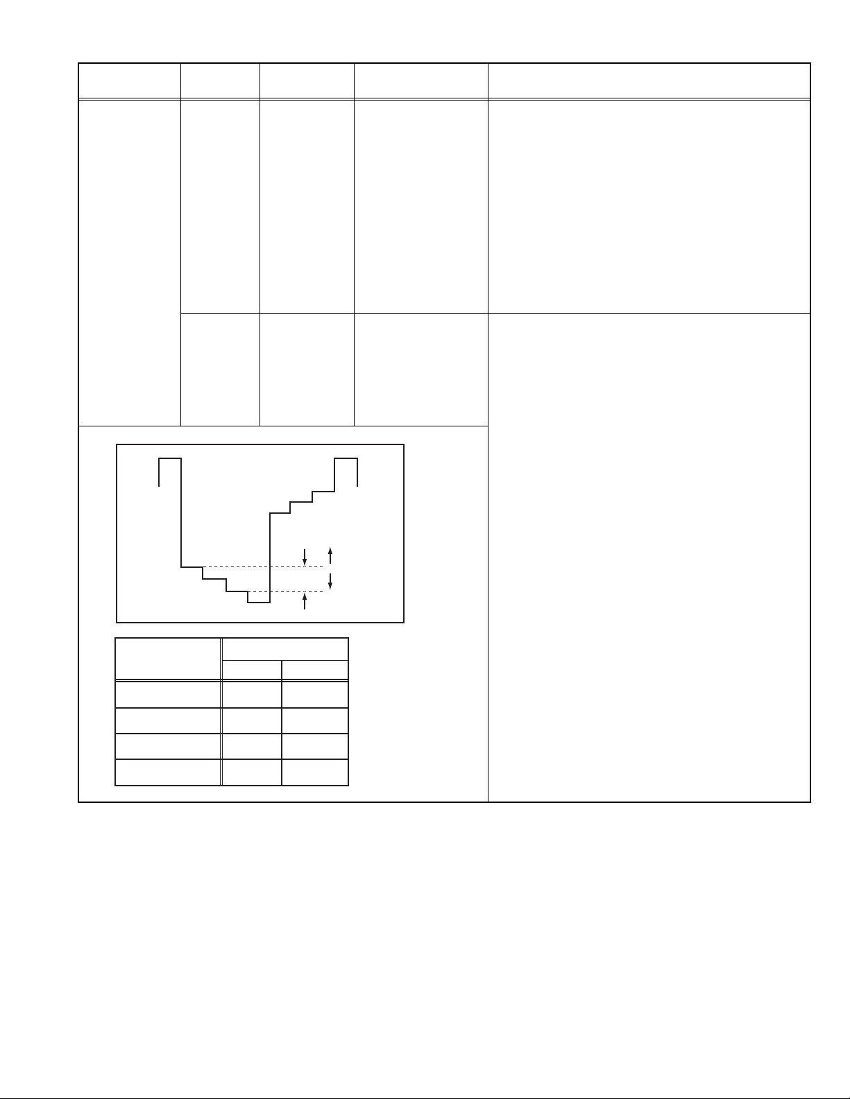
4.8.4 DEFLECTION CIRCUIT
• There are 2 modes of adjustment (setting value) 50Hz mode and 60Hz mode, depending upon the kind of signals (vertical frequency
50Hz / 60Hz).
• When adjusted in 50Hz mode and 60Hz mode will be automatically set.
The setting (adjustment) using the REMOTE CONTROL UNIT is made on the basis of the initial setting values.The setting
values which adjust the screen to the optimum condition can be different from the initial setting values.
• Make sure that the adjustment is properly done on the screen of 60Hz mode.
NOTE:
• Adjust to make both 50Hz & 60Hz are the same v. size and fine straight line.
• When adjust again, adjust 50Hz mode first.
• When adjust in 60Hz mode, only 60Hz mode is adjust.
Item
V. HEIGHT /
V. POSITION
Measuring
instrument
Signal
generator
Remote
control unit
Test point Adjustment part Description
[3. DEF]
1. VER. POSITION
3. VER. HEIGHT
(1) Receive a crosshatch signal.
(2) Select 3. DEF from the SERVICE MENU.
(3) Select < 1. VER. POSITION >.
(4) Set the initial setting value of < 1. VER. POSITION >.
(5) Adjust < 1. VER. POSITION > to make the vertical
centre fall on the display centre.
(6) Select <3. VER. HEIGHT >.
(7) Set the initial setting value of <3. VER. HEIGHT >.
Screen
size
Picture
size
100%
(8) Adjust <3. VER. HEIGHT > to make the vertical
screen size be 92% of the picture size.
H. POSITION Signal
generator
Remote
control unit
V.LINEARITY /
V.S-CURVE
Signal
generator
Remote
control unit
(A)
Fig.1
Fig.2
[3. DEF]
2. HOR. POSITION
(B)
[3. DEF]
4. VER. LIN.
5. VER. SCURVE
Top
Centre
(1) Receive a circle pattern signal.
(2) Select 3. DEF from the SERVICE MENU.
(3) Select < 2. HOR. POSITION >.
(4) Set the initial setting value of < 2. HOR. POSITION >.
(5) Adjust <2.HOR. POSITION> to be equal the width of
(A) and (B) as shown in Fig.2.
• If the vertical linearity is noticeably deteriorated, perform
the following steps.
(1) Receive a crosshatch signal.
(2) Select 3. DEF from the SERVICE MENU.
(3) Select < 4. VER. LIN. >.
(4) Set the initial setting value of < 4. VER. LIN. >.
(5) Select < 5. VER. SCURVE >.
(6) Set the initial setting value of < 5. VER. SCURVE >.
(7) Adjust < 4. VER. LIN. > and < 5. VER. SCURVE >
so that the space of upper and lower lines as shown
in Fig.3 on TOP, CENTRE and BOTTOM become
uniform.
1-22 (No.YA416)
Bottom
Fig.3
Page 23
4.8.5 VIDEO CIRCUIT
The setting (adjustment) using the REMOTE CONTROL UNIT is made on the basis of the initial setting values. The setting
values which adjust the screen to the optimum condition can be different from the initial setting values. Do not change the
initial setting values of the setting items not listed in "ADJUSTMENT PROCEDURE".
Item
WHITE
BALANCE
(LOW LIGHT)
Measuring
instrument
Signal
generator
Remote
control unit
Test point Adjustment part Description
[2.V/C]
1. CUT OFF (R)
1. CUT OFF (G)
1. CUT OFF (B)
SCREEN VR
[IN HVT]
(1) Receive a black and white signal (colour off).
(2) Select 2. V/C from the SERVICE MENU.
(3) Select < 1. CUT OFF >.
(4) Set the initial setting value of < 1. CUT OFF >.
(5) Press the [1] key to show the single horizontal line
on screen.
(6) Turn the SCREEN VR fully counter-clockwise, then
slowly turn it clockwise to where one of a red, blue or
KEY ASSIGNMENT OF REMOTE CONTROL UNIT
green colour is faintly visible.
(7) Adjust the two colors which did not appear until the
CUTOFF OFF
(H.LINE OFF)
CUTOFF ON
(H.LINE ON)
R. CUTOFF( )
R. CUTOFF( )
123
456
789
G.CUTOFF( )
B. CUTOFF( )
B. CUTOFF( )
G.CUTOFF( )
single horizontal line that is displayed becomes
white using the [4] to [9] keys.
(8) Turn the SCREEN VR to where the single horizontal
line glows faintly.
(9) Press the [2] key to turn off the single horizontal line.
(10) Press the [DISPLAY] key twice to return to the nor-
mal screen.
R G B
WHITE
BALANCE
(HIGH LIGHT)
Signal
generator
Remote
control unit
KEY ASSIGNMENT OF REMOTE CONTROL UNIT
R. DRIVE( )
SUB BRIGHT Remote
control unit
SUB
CONTRAST
Remote
control unit
123
456
789
R B
[2.V/C]
2. DRIVE (R)
2. DRIVE (B)
B. DRIVE( )
B. DRIVE( )R. DRIVE( )
[2. V/C]
3. BRIGHT
[2. V/C]
4. CONT.
(1) Receive a black and white signal (colour off).
(2) Select 2. V/C from the SERVICE MENU.
(3) Select < 2. DRIVE >.
(4) Set the initial setting value of < 2. DRIVE >.
(5) Adjust the screen until it becomes white using the
[4], [6], [7] and [9] keys.
(6) Press the [DISPLAY] key twice to return to the nom-
al screen.
(1) Receive any broadcast.
(2) Select 2. V/C from the SERVICE MENU.
(3) Select < 3. BRIGHT >.
(4) Set the initial setting value of < 3. BRIGHT >.
(5) If the brightness is not the best with the initial setting
value, make fine adjustment until you get the best
brightness.
(1) Receive any broadcast.
(2) Select 2. V/C from the SERVICE MENU.
(3) Select < 4. CONT >.
(4) Set the initial setting value of < 4. CONT >.
(5) If the contrast is not the best with the initial setting
value, make fine adjustment until you get the best
contrast.
(No.YA416)1-23
Page 24
Item
Measuring
instrument
SUB COLOUR Remote
control unit
Signal
generator
Oscilloscope
Remote
control unit
W
Y
MODEL
AV-2106BE
AV-21B16/L
AV-21BMG6B/G
Test point Adjustment part Description
[2. V/C]
5. COLOUR
(PAL / SECAM / NTSC)
TP-47G/R
TP-E
[CRT SOCKET
[2. V/C]
5. COLOUR
(PAL / SECAM / NTSC)
PWB]
B
R
M
0V
(A)
C
G
PAL SECAM NTSC3.58 NTSC4.43
+12V +6V +8V (VDO) ---
+12V +6V +8V (VDO) ---
+12V +6V +8V (RF) ---
(+)
Voltage setting (A)
[Method of adjustment without measuring instrument]
PAL COLOUR
(1) Receive a PAL broadcast.
(2) Select 2. V/C from the SERVICE MENU.
(3) Select < 5. COLOUR >.
(4) Set the initial setting value of < 5. COLOUR >.
(5) If the colour is not the best with the initial setting
value, make fine adjustment until you get the best
colour.
SECAM COLOUR
(1) Receive a SECAM broadcast.
(2) Make fine adjustment of SECAM COLOUR as
previously.
NTSC 3.58 COLOUR
(1) Receive a NTSC 3.58MHz broadcast.
(2) Make similar fine adjustment of NTSC 3.58
COLOUR as previously.
NTSC 4.43 COLOUR
(1) When NTSC 3.58 adjustment completed, NTSC
4.43 will be automatically set at the respective
values.
[Method of adjustment using measuring instrument]
PAL COLOUR
(1) Receive a PAL full field colour bar signal (75%
white).
(2) Select 2. V/C from the SERVICE MENU.
(3) Select < 5. COLOUR >.
(4) Set the initial setting value of < 5. COLOUR >.
(5) Connect the oscilloscope between TP-47G/R and
TP-E.
(6) Adjust PAL COLOUR to bring the value of (A) in
the voltage table.
SECAM COLOUR
(1) Receive a SECAM full field colour bar signal (75%
white).
(2) Set the initial setting value of SECAM COLOUR .
(3) Adjust SECAM COLOUR to bring the value of (A)
in the voltage table.
NTSC 3.58 COLOUR
(1) Receive a NTSC 3.58 full field colour bar signal
(75% white).
(2) Set the initial setting value of NTSC 3.58
COLOUR.
(3) Adjust NTSC 3.58 COLOUR to bring the value of
(A) in the voltage table.
NTSC 4.43 COLOUR
(1) When NTSC 3.58 is set, NTSC 4.43 will be
automatically set at the respective values.
AV-21BMG6/G
1-24 (No.YA416)
+12V +6V +8V (RF) ---
Page 25
Item
Measuring
instrument
SUB TINT Signal
generator
Remote
control unit
Signal
generator
Oscilloscope
Remote
control unit
Test point Adjustment part Description
[2. V/C]
6. TINT
[Method of adjustment without measuring instrument]
NTSC 3.58 TINT
(1) Receive a NTSC 3.58 full field colour bar signal
(75% white).
(2) Select 2. V/C from the SERVICE MENU.
(3) Select < 6. TINT >.
(4) Set the initial setting value of < 6. TINT >.
(5) If you cannot get the best tint with the initial setting
value, make fine adjustment until you get the best
tint.
NTSC 4.43 TINT
(1) When NTSC 3.58 is set, NTSC 4.43 will be
automatically set at the respective values.
TP-47G/R
TP-E
[CRT SOCKET
PWB]
[2. V/C]
6. TINT
[Method of adjustment using measuring instrument]
NTSC 3.58 TINT
(1) Receive a NTSC 3.58 full field colour bar signal
(75% white).
(2) Select 2. V/C from the SERVICE MENU.
(3) Select < 6. TINT >.
(4) Set the initial setting value of < 6. TINT >.
(5) Connect the oscilloscope between TP-47G/R and
TP-E.
(6) Adjust NTSC 3.58 TINT to bring the value of (B)
B
R
M
NTSC 4.43 TINT
in the voltage table in the left.
(1) When NTSC 3.58 is set, NTSC 4.43 will be
(-)
automatically set at the respective values.
W
MODEL
AV-2106BE
AV-21B16/L
AV-21BMG6B/G
AV-21BMG6/G
Y
C
G
Voltage setting (A)
NTSC3.58 NTSC4.43
+6V (VDO) ---
+6V (VDO) ---
+6V (RF) ---
+6V (RF) ---
0V
(B)
(+)
(No.YA416)1-25
Page 26
Item
SECAM BLACK
OFFSET
Measuring
instrument
Signal
generator
Remote
control unit
4.8.6 VSM PRESET SETTING
Item
Measuring
instrument
VSM PRESET Remote
control unit
TINT **
COLOUR **
BRIGHT **
CONT.
SHARP **
/ : SELECT
- / + : OPREATE DISP : EXIT
Test point Adjustment part Description
[2. V/C]
7. SECAM BL ADJUST
(1) Input a SECAM full field colour bar signal.
(2) Select 2. V/C from the SERVICE MENU.
(3) Select < 7. SECAM BL ADJUST >.
(4) Set the initial setting value of < 7. SECAM BL
ADJUST >.
(5) Switch the [1] key (colour OFF) and [2] key (colour
ON) and make sure that there is no colour on the
black and white screen.
(6) If the black and white screen is not best with the
initial setting value, make fine adjustment until you
get the best black and white screen.
(7) While watching the screen, adjust the value to be the
same colour between ON & OFF by [1] or [2] key.
(8) Press the [DISPLAY] key twice to return to the
normal screen.
Test point Adjustment part Description
[4. VSM PRESET]
TINT
COLOUR
BRIGHT
CONT.
SHARP
(1) Select 4. VSM PRESET from the SERVICE MENU.
(2) Set the PICTURE MODE to BRIGHT.
(3) Select < TINT >.
(4) Set the initial setting value of < TINT > as shown in
the below table.
(5) Select < COLOUR > to < SHARP > in turn, and set
the values.
(6) Respectively select the "SOFT" and "STANDARD".
BRIGHT
**
Make similar adjustment as same step as above.
[4.VSM PRESET]
Setting
item
Variable
range
Initial setting value
BRIGHT
STANDARD
SOFT
TINT 0 - 30 15 15 15
COLOUR 0 - 30 15 15 15
BRIGHT 0 - 30 15 15 15
CONT. 0 - 30 30 15 11
SHARP 0 - 30 15 15 12
1-26 (No.YA416)
Page 27
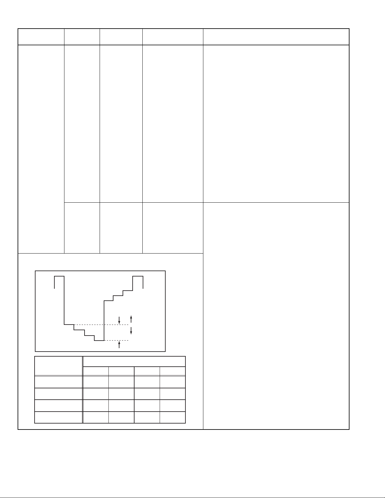
4.8.7 PURITY AND CONVERGENCE
PURITY ADJUSTMENT
Note:
The final adjustment of CONVERGENCE must be done after
the FOCUS adjustment. (CONVERGENCE is changed by
FOCUS adjustment.)
When makes difference by FOCUS adjustment, should be
reconfirming PURITY adjustment.
(1) Demagnetize CRT with the demagnetizer.
(2) Loosen the retainer screw of the deflection yoke.
CRT
WEDGE
DEFLECTION
YOKE
P
4 6
P / C
MAGNETS
(3) Remove the wedges.
(4) Input a green raster signal from the signal generator, and
turn the screen to green raster.
(5) Move the deflection yoke backward.
(6) Bring the long lug of the purity magnets on the short lug and
position them horizontally. (Fig.2)
(7) Adjust the gap between two lugs so that the GREEN
RASTER will come into the centre of the screen. (Fig.3)
(8) Move the deflection yoke forward, and fix the position of the
deflection yoke so that the whole screen will become green.
(9) Insert the wedge to the top side of the deflection yoke so that
it will not move.
(10) Input a crosshatch signal.
• P/C MAGNETS
P : PURITY MAGNET
4 : 4 POLES (convergence magnets)
6 : 6 POLES (convergence magnets)
Fig.1
PURITY MAGNETS
Long lug
Short lug
Bring the long lug over the short lug
and position them horizontally.
Fig.2
(FRONT VIEW)
GREEN RASTER
(11) Verify that the screen is horizontal.
(12) Input red and blue raster signals, and make sure that purity
is properly adjusted.
CENTRE
Fig.3
(No.YA416)1-27
Page 28
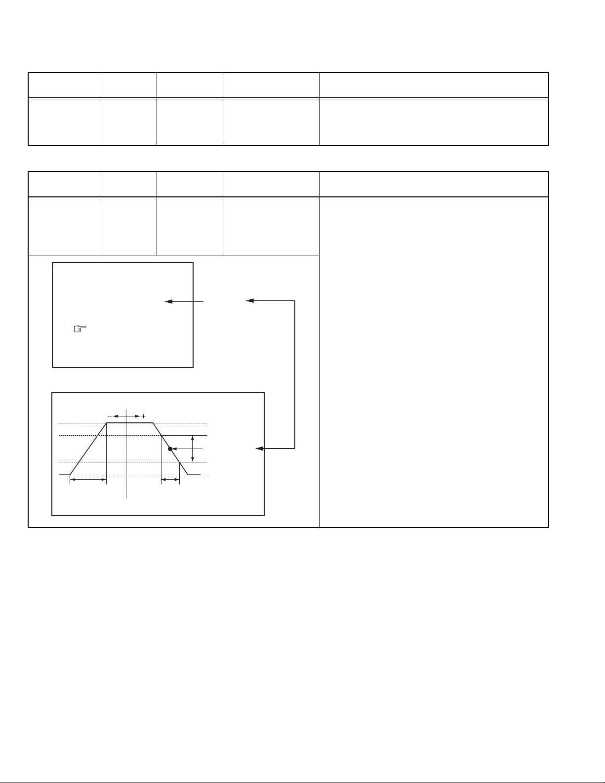
STATIC CONVERGENCE ADJUSTMENT
(1) Input a crosshatch signal.
(2) Using 4-pole convergence magnets, overlap the red and
blue lines in the centre of the screen (Fig.1) and turn them
to magenta (red/blue).
(3) Using 6-pole convergence magnets, overlap the magenta
(red/blue) and green lines in the centre of the screen and
turn them to white.
(4) Repeat 2 and 3 above, and make best convergence.
DYNAMIC CONVERGENCE ADJUSTMENT
(1) Move the deflection yoke up and down and overlap the lines
in the periphery. (Fig. 2)
(2) Move the deflection yoke left to right and overlap the lines in
the periphery. (Fig. 3)
(3) Repeat 1 and 2 above, and make best convergence.
(4) Adjust XV by XV coil. (Fig.4)
(FRONT VIEW)
Fig.1
(FRONT VIEW)
GREEN
RED
BLUE
RED
BLUE
GREEN
Fig.2
(FRONT VIEW)
GREEN GREEN
RED
BLUE
BLUE
BLUE
RED
GREENGREEN
BLUE
RED
RED
RED
GREEN
BLUE
• After adjustment, fix the wedge at the original position. Fasten
the retainer screw of the deflection yoke. Fix the P/C magnets
with glue.
SECTION 5
TROUBLESHOOTING
This service manual does not describe TROUBLESHOOTING.
(FRONT VIEW)
Xv
BLUE
GREEN
RED
Fig.3
GREEN
Fig.4
1-28 (No.YA416)
Page 29

Victor Company of Japan, Limited
Display Category 12, 3-chome, Moriya-cho, Kanagawa-ku, Yokohama-city, Kanagawa-prefecture, 221-8528, Japan
(No.YA416)
Printed in Japan
VPT
Page 30

COLOUR TELEVISION
INSTRUCTIONS
Thank you for buying this JVC
colour television.
To make sure you understand how to
use your new TV, please read this
manual thoroughly before you begin.
AV-14A16
AV-14F16
AV-21B16
AV-21F16
AV-21T16
Contents
Safety precautions 2
Preparation 3
1 Confirm which remote control you have
2 Inserting the batteries
3
Connecting the aerial and external devices
4 Connecting the power cord
5 SETUP TOUR
...................................
........................
..............................................
......
...
Basic operation 7
Remote control buttons and functions 8
PICTURE MODE button
COLOUR SYSTEM button
SOUND SYSTEM button
DISPLAY button
RETURN + button
CHANNEL SCAN button
MUTING button
OFF TIMER button
.................................
.............................
...............................
.............................................
..........................................
................................
.............................................
.........................................
Using the TV’s menus 10
Basic operation
ON TIMER
...........................................................
INPUT
...............................................................
VNR
AUTO SHUTOFF
CHILD LOCK
BLUE BACK
SETUP TOUR
LANGUAGE
AUTO CH PRESET
MANUAL CH PRESET
..............................................................
SKIP
Picture Adjustments
............................................
.....................................................
..........................................
.................................................
..................................................
...............................................
..................................................
.......................................
..................................
....................................
10
11
11
12
12
12
12
13
13
13
14
15
15
Using the buttons on the TV 16
Troubleshooting 18
Specifications 19
3
3
4
6
6
8
8
8
9
9
9
9
9
GGT0106-001B-H
0506-NIC-JMT
© 2006 Victor Company of Japan, Limited
Page 31

Safety precautions
WARNING
•To prevent fire or shock hazard, do not expose the TV to rain or moisture.
CAUTION
• Operate only from the power source indicated on the rear of the TV.
•Avoid damaging the power cord and mains plug. When you unplug the TV, pull it out by
the mains plug. Do not pull on the power cord.
•Never block or cover the cabinet openings for
ventilation. Never install the TV where good
ventilation is unattainable. When installing
this TV, leave spaces for ventilation around
the TV more than the minimum distances
shown in the diagram.
• Do not allow objects or liquid into the
cabinet openings.
• In the event of a fault, unplug the TV and call a service technician. Do not attempt to
repair it by yourself or remove the rear cover.
• The surface of the TV screen is easily damaged. Be very careful with it when handling
the TV. Should the TV screen become soiled, wipe it with a soft dry cloth. Never rub it
forcefully. Never use any cleaner or detergent on it.
•This TV can be turned on/ off power by connecting/ disconnecting the AC Plug into AC
outlet. While this TV is being installed, enough space should be reserved for connecting/
disconnecting the AC Plug into AC outlet by hand.
10 cm 15 cm
10 cm
15 cm
2
Page 32

Preparation
1 Confirm which remote control you have
RM-C360GY
POWER
COLOUR
TV/VIDEO
OFF
TIMER
CHANNEL
SCAN
DISPLAY
SYSTEM
SOUND
RETURN+
PICTURE
MODE
123
456
789
--
0-/
MUTING
MENU
CHANNEL
REMOTE CONTROL UNIT
RM-C360GY
2 Inserting the batteries
Correctly insert two batteries, observing the , and
. polarities and inserting the . end first.
CAUTION:
Follow the cautions printed on the batteries.
Notes:
• Use AA/R6/UM-3 dry cell batteries.
• If the remote control does not work properly, fit new
batteries.
The supplied batteries are for testing, not regular use.
VOLUME
3
Page 33

Preparation
3 Connecting the aerial and external devices
•For further details, refer to the manuals provided with the devices you are connecting.
• Connecting cables are not supplied.
• The front and rear AUDIO/VIDEO input jacks are directly connected so that input to either jack
is output through both. You cannot provide input to both the front and rear jacks at the same
time. Disconnect one input, or use one of the jacks as an output jack only (for monitoring or
recording).
■ Connecting the aerial and VCR
Connecting the aerial
VHF/UHF outdoor aerial
VIDEO
AUDIO
IN
(VIDEO - 1)
OUT
• Illustration of AV-14A16.
Connecting the aerial and VCR
VHF/UHF outdoor aerial
4
1
2
To RF
output
To aerial input
To video
output
VIDEO
AUDIO
IN
(VIDEO - 1)
OUT
3
To audio
output
VCR
• Illustration of AV-14A16.
Page 34

Preparation
■ Connecting other external devices
VIDEO
AUDIO
• Illustration of AV-14A16.
Camcorder or TV game
IN
(VIDEO - 1)
OUT
To audio
output
VCR (for playing)
VCR (for recording)
To audio
input
To video
output
To video
output
To video
input
To audio
output
VIDEO AUDIO
IN
MENU CHANNEL
• Illustration of AV-14A16.
Headphones
• Use the headphones with a stereo mini jack (3.5 mm in diameter). When you connect the
headphones, the TV speakers go off.
5
Page 35

Preparation
4 Connecting the power cord
Connect the power cord to the AC outlet.
Operate only from the power source indicated on the rear of the TV.
5 SETUP TOUR
When the TV is first turned on it enters the SETUP TOUR mode, and the JVC logo is
displayed. Follow the instructions on the on-screen display to perform the SETUP TOUR.
• In case of resetting that the reason for such as removal, you can set the SETUP TOUR
function on the “MENU 3” menu. For details, see page 13.
1 Press the Main power button
on the TV.
The POWER lamp or POWER/ON
TIMER lamp lights. After the JVC
logo has been displayed, the TV
automatically switches to the
language setting mode.
SETUP TOUR
SETUP TOUR
LANGUAGE
ENGLISH
NEXT
EXIT BY
OPERATE BY -+
DISPLAY
2 Press the MENU M buttons to
select the on-screen language.
3 Press the MENU y button.
The AUTO PROGRAMMING function
will start and the indicator blinks.
SETUP TOUR
• Illustration of AV-21F16
DISPLAY
button
MENU –/+
buttons
E
ON TIMER POWER
POWER lamp Main power button
SYSTEM
SOUND
COLOUR
123
TV/VIDEO
456
OFF
789
TIMER
CHANNEL
RETURN+
SCAN
DISPLAY
MENU
CHANNEL
VOLUME
REMOTE CONTROL UNIT
RM-C360GY
POWER
PICTURE
MODE
0-/
MUTING
--
MENU /
buttons
NOW PROGRAMMING
STOP BY -+
•To stop the AUTO PROGRAMMING function, press the MENU m buttons.
When you press stop, it will display “SETUP TOUR THANK YOU!”.
When all the TV channels that can be received on your TV have been preset, the
display goes out and the AUTO PROGRAMMING function operation is completed.
6
• If a TV channel you want to view is not set to the channel, set it with the MANUAL CH
PRESET function. For details, see page 14.
Page 36

Basic operation
POWER
COLOUR
TV/VIDEO
OFF
TIMER
CHANNEL
SCAN
DISPLAY
CHANNEL
SYSTEM
SOUND
RETURN+
REMOTE CONTROL UNIT
RM-C360GY
PICTURE
MODE
123
456
789
--
0-/
MUTING
MENU
VOLUME
1 Press the POWER button to turn
your TV on.
• If your TV does not turn on, press the
Main power button on the TV then press
the POWER button again.
•You can also turn on your TV by pressing
any of the following buttons;
- the CHANNEL m button
- the Number buttons
- the TV/VIDEO button
2 Select a channel.
■ Press the CHANNEL m button.
• Up/down selection cannot be selected
for channels to which the SKIP has been
set to “YES”. See page 15.
■ Press the Number buttons to enter
the channel number.
• If you want to enter a two-digit number,
press the -/-- button to select the two
digit mode “--”, then enter the channel
number.
3 Press the VOLUME M button to
adjust the sound.
4To turn your TV off, press the
POWER button.
•We recommend that you press the Main
power button on the TV to turn the main
power off if you do not plan to use your
TV for a long time or if you wish to save
energy.
If the picture is not clear:
Press the COLOUR SYSTEM button to
select another colour system, see page 8.
If the sound is not clear:
Press the SOUND SYSTEM button to select
another sound system, see page 8.
Viewing Images from an External
Device:
Press the TV/VIDEO button to select the
VIDEO mode.
•You can also use the INPUT function to select
the VIDEO mode. For details, refer to page 11.
7
Page 37

Remote control buttons and functions
PICTURE MODE button
You can select one of three picture
adjustment settings as you like.
Press this button to select a mode.
BRIGHT:
Heightens contrast and sharpness.
STANDARD:
Standardizes picture adjustments.
SOFT:
Softens contrast and sharpness.
•Pressing this button returns all the picture
settings in the “MENU 4” to their default
settings.
COLOUR SYSTEM button
If the picture is not clear or no colour
appears, change the current colour system
to another colour system.
Press this button to select the colour
system.
In TV mode (channel 1 to 99 and AV):
AUTO PAL
SECAM
In VIDEO mode:
AUTO PAL
NTSC4.43
SECAM
NTSC3.58
AUTO:
Automatic colour system selection.
•For the colour systems in each country or
region, see the table“Broadcasting systems”
on page 19.
• If the picture is not normal in the AUTO
mode, change the AUTO mode to another
colour system.
SOUND SYSTEM button
If the sound is not clear even when the
picture appears normal, change the
current sound system to another sound
system.
Press this button to select the sound
system.
B/G I D/K
•For the sound systems in each country or
region, see the table “Broadcasting systems”
on page 19.
•You cannot select any sound system when in
a VIDEO mode.
8
Page 38

Remote control buttons and functions
DISPLAY button
You can continuously display the current
channel number or VIDEO mode on the
screen.
Press this button.
To turn the display off, press this button
again.
• When selecting a channel or VIDEO mode
with no input signal, indication of selected
channel or VIDEO mode becomes fixed on the
screen.
RETURN + button
You can set a channel you frequently view
to the Return Channel and you can view
that channel at any time with one-touch.
To set the channel to the Return
Channel:
1 Select the channel you want to set
to the Return Channel.
2 Press this button and hold until the
message “RETURN PLUS
PROGRAMMED!” appears.
• When you turn off the TV, the Return
Channel setting is cancelled.
To view the Return Channel:
Press this button.
•You can view two channels (current channel
and Return Channel) alternately by pressing
this button.
To cancel the Return Channel setting:
Press this button and hold until the
message“RETURN PLUS CANCELLED!”
appears.
If no channel is set to the Return
Channel:
You can view the channel selected right
before the current channel by pressing
this button.
CHANNEL SCAN button
You can quickly view all TV channels
programmes that you can view on your
TV, and search for the programme you
want to view.
1 Press this button to start scanning
TV channels.
The TV channel programmes are each
displayed for several seconds.
• The programmes of TV channels for which
the SKIP function is set to “YES” are not
displayed. (See page 15.)
2 When you find the programme you
want to view, press this button
again to stop scanning.
MUTING button
You can turn the sound off instantly.
Press this button.
To turn the sound on, press this button
again.
OFF TIMER button
You can set the TV to automatically turn
off after a set time.
Press this button to select the period of
time.
•You can set the period of time to a maximum
of 120 minutes in 10 minute increments.
•1 minute before the OFF TIMER function
turns off the TV, “GOOD NIGHT!” appears.
To display the remaining time, press this
button once.
To cancel the OFF TIMER function, press
this button to set the period of time to 0.
• The OFF TIMER function will not turn off the
TV’s main power.
9
Page 39

Using the TV’s menus
This TV has a number of functions you can operate using the menus. To use all your TV’s
functions fully, you need to understand how to use the menus.
2 Repeatedly press the MENU T
buttons to display a desired
POWER
SOUND
123
456
789
RETURN
+
0-/
MENU
VOLUME
REMOTE CONTROL UNIT
RM-C360GY
PICTURE
MODE
MUTING
--
MENU /
buttons
DISPLAY
button
MENU –/+
buttons
COLOUR
TV/VIDEO
OFF
TIMER
CHANNEL
SCAN
DISPLAY
CHANNEL
SYSTEM
■ Basic operation
1 Press the MENU T buttons.
One of the 4 menus is displayed.
MENU number
MENU 1
The icon on
the left indicates
the currently
selected function.
INPUT TV
ON TIMER
PR 1 0:00
VNR OFF
SELECT BY EXIT BY
OPERATE BY -+
DISPLAY
menu.
• If you hold down the y button, the next
menu is displayed.
• If the selected function is on the first line,
pressing the r button displays the
preceding menu.
3 Repeatedly press the MENU T
buttons to select a desired
function.
4 Press the MENU M buttons to
change function settings.
Example:
MENU 2
AUTO SHUTOFF OFF
CHILD LOCK OFF
BLUE BACK ON
SELECT BY EXIT BY
OPERATE BY -+
• With some functions, the operation
method may differ.
DISPLAY
Changes the AUTO
SHUTOFF setting.
MENU 2
AUTO SHUTOFF ON
CHILD LOCK OFF
BLUE BACK ON
SELECT BY EXIT BY
OPERATE BY -+
DISPLAY
5 Press the DISPLAY button to turn
the display off.
•To operate a menu using the buttons on
the front panel of the TV, refer to
“Operating menus” on page 17.
10
Page 40

Using the TV’s menus
ON TIMER
Your TV will automatically turn on and
tune into the channel you set after the
period of time you set.
1 Press MENU T to display the
“MENU 1” menu, then select
“ON TIMER”.
MENU 1
INPUT TV
ON TIMER
PR 1 0:00
VNR OFF
OPERATE BY VOL-+
SELECT BY EXIT BY
PROGRAM BY -+
2 Press MENU M to select a channel
you want to view when the TV turns
on.
3 Press VOLUME M to select the
period of time after which you want
to turn on the TV.
The ON TIMER function starts.
• Each time you press the button, the period
of time changes in 15 minute intervals (up
to 12 hours).
To cancel the ON TIMER function,
press the VOLUME m button to set the
period of time to “0:00”.
4 Press DISPLAY to turn the display
off.
• If you turn off the TV’s main power by
pressing the Main power button, the ON
TIMER function is canceled.
• If you do not turn off the TV after starting
the ON TIMER function, the channel will
automatically switch to the channel set for
the ON TIMER function.
Channel
No.
DISPLAY
When the time set for the ON TIMER
function is reached:
The TV automatically turns on and the
channel set for the ON TIMER function is
displayed.
•For safety reasons the TV will automatically
turn off if no operations are made within
approximately two hours after the TV is
turned on with the ON TIMER function.
• The OFF TIMER function and AUTO
SHUTOFF function have priority over the ON
TIMER function.
INPUT
You can view images from VCRs or other
devices connected to your TV.
1 Press MENU T to display the
“MENU 1” menu, then select
“INPUT”.
MENU 1
INPUT TV
ON TIMER
PR 1 0:00
VNR OFF
SELECT BY EXIT BY
OPERATE BY -+
2 Press MENU M to select the VIDEO
mode.
While you press MENU –/+, it will
switch to TV mode and VIDEO mode
alternately.
DISPLAY
11
Page 41

Using the TV’s menus
VNR (Video Noise Reduction)
You can reduce the picture noise.
1 Press MENU T to display the
“MENU 1” menu, then select “VNR”.
MENU 1
INPUT TV
ON TIMER
PR 1 0:00
VNR ON
SELECT BY EXIT BY
OPERATE BY -+
DISPLAY
2 Press MENU M to select “ON”.
To cancel the VNR function, select
“OFF”.
AUTO SHUTOFF
You can set your TV to turn off if no
signals are received for about 15 minutes
or longer after the end of a broadcast.
1 Press MENU T to display the
“MENU 2” menu, then select “AUTO
SHUTOFF”.
MENU 2
AUTO SHUTOFF ON
CHILD LOCK ON
BLUE BACK ON
SELECT BY EXIT BY
OPERATE BY -+
2 Press MENU M to select “ON”.
To cancel the AUTO SHUTOFF function,
select “OFF”.
• The AUTO SHUTOFF function does not
turn off the TV’s main power.
• The AUTO SHUTOFF will not work for a
VIDEO mode.
DISPLAY
CHILD LOCK
You can disable the front control buttons
of the TV.
When this function is set to “ON”, the TV
can be operated using only the remote
control.
Use this function to prevent children from
operating the TV without parental consent.
1 Press MENU T to display the
“MENU 2” menu, then select “CHILD
LOCK”.
MENU 2
AUTO SHUTOFF ON
CHILD LOCK ON
BLUE BACK ON
SELECT BY EXIT BY
OPERATE BY -+
DISPLAY
2 Press MENU M to select “ON”.
To cancel the CHILD LOCK function,
select “OFF”.
• The CHILD LOCK function is canceled when
you turn the power off.
BLUE BACK
You can mute the sound and change the
picture into a blue screen while no signals
are received by the TV, or when the
signals are unstable.
1 Press MENU T to display the
“MENU 2” menu, then select “BLUE
BACK”.
MENU 2
AUTO SHUTOFF ON
CHILD LOCK ON
BLUE BACK ON
SELECT BY EXIT BY
OPERATE BY -+
DISPLAY
12
2 Press MENU M to select “ON”.
To cancel the BLUE BACK function,
select “OFF”.
•To view a broadcast even when the
reception signal is poor, set the BLUE
BACK function to “OFF”.
•Even when the BLUE BACK function is set
to “OFF”, the sound may not be audible.
Page 42

Using the TV’s menus
SETUP TOUR
You can start the SETUP TOUR function.
1 Press MENU T to display the
“MENU 3” menu, then select
“SETUP TOUR”.
MENU 3
AUTO CH PRESET
MANUAL CH PRESET
SETUP TOUR
LANGUAGE ENGLISH
SELECT BY EXIT BY
OPERATE BY -+
DISPLAY
2 Press MENU M.
JVC logo is appear and the SETUP
TOUR function will start.
For details, see page 6.
LANGUAGE
You can select the language for the onscreen display.
1 Press MENU T to display the
“MENU 3” menu, then select
“LANGUAGE”.
MENU 3
AUTO CH PRESET
MANUAL CH PRESET
SETUP TOUR
LANGUAGE ENGLISH
SELECT BY EXIT BY
OPERATE BY -+
2 Press MENU M to select
language.
The on-screen display indications are
in the selected language.
DISPLAY
AUTO CH PRESET
You can automatically preset all TV
channels that can be received by your TV
to channels.
1 Press MENU T to display the
“MENU 3” menu, then select “AUTO
CH PRESET”.
MENU 3
AUTO CH PRESET
MANUAL CH PRESET
SETUP TOUR
LANGUAGE ENGLISH
SELECT BY EXIT BY
OPERATE BY -+
2 Press MENU M to start the AUTO
CH PRESET function.
“>>>ON SEARCH” is displayed on
the screen.
When all the TV channels that can be
received on your TV have been preset,
the display goes out and the AUTO CH
PRESET function operation is
completed.
To stop the AUTO CH PRESET:
Press the MENU m buttons.
• The AUTO CH PRESET function does not
preset a TV channel to the AV channel
(channel number 0).
• If the TV cannot preset the TV channel you
want to view, preset it manually. For details,
see “MANUAL CH PRESET” on page 14.
DISPLAY
13
Page 43

Using the TV’s menus
MANUAL CH PRESET
You can manually preset desired TV
channels to desired channels.
1 Press MENU T to display the
“MENU 3” menu, then select
“MANUAL CH PRESET”.
MENU 3
AUTO CH PRESET
MANUAL CH PRESET
SETUP TOUR
LANGUAGE ENGLISH
SELECT BY EXIT BY
OPERATE BY -+
2 Press MENU M.
The sub-menu is displayed.
MANUAL
FINE
SKIP NO
SOUND SYSTEM B/G
EXIT
SELECT BY PR 1 VL
PROGRAM BY -+ EXIT BY
SEARCH BY VOL-+
• The channel number is displayed as a PR
number. For example, channel 1 will be
displayed as PR 1. However, the AV
channel will be displayed as AV.
3 Press MENU M to select the
channel number.
4 Press VOLUME M to start
searching for the TV channel.
“>>>” or “<<<” is displayed on the
screen.
When the TV finds a TV channel, the
“>>>” or “<<<” display goes out,
and the TV channel is preset to the
currently selected channel number.
• If the TV channel you want to preset is not
displayed, repeat step 4 until the TV finds
the TV channel you want to preset.
•To stop the MANUAL CH PRESET function,
press any button other than the VOLUME
m button.
DISPLAY
DISPLAY
If the picture is not clear:
Fine-tune the TV channel.
1 Press MENU t to select “FINE”.
MANUAL
FINE
SKIP NO
SOUND SYSTEM B/G
EXIT
SELECT BY PR 3 VL
PROGRAM BY -+ EXIT BY
FINE BY VOL-+
DISPLAY
2 Hold VOLUME m down to fine-tune
the TV channel so that the best image
is displayed on screen.
“>” or “<” indicates that the TV is finetuning the TV channel.
If the sound is not clear:
1 Press MENU t to select “SOUND
SYSTEM”.
MANUAL
FINE
SKIP NO
SOUND SYSTEM B/G
EXIT
SELECT BY PR 3 VL
PROGRAM BY -+ EXIT BY
CHANGE BY VOL-+
DISPLAY
2 Press VOLUME m to select the
appropriate sound system.
•For the sound systems in each country
or region, refer to the table
“Broadcasting systems” on page 19.
5 Press MENU T to select
“MANUAL”.
6 Repeat steps 3 to 5 if you want to
preset another TV channel to a
channel.
14
Page 44

Using the TV’s menus
SKIP
You can set undesired channels to be
skipped. Channels set to be skipped
cannot be selected by the CHANNEL m
buttons nor the CHANNEL SCAN button.
• Channels to which TV channels have not
been preset are automatically set to be
skipped.
1 Press MENU T to display the
“MENU 3” menu, then select
“MANUAL CH PRESET”.
2 Press MENU M.
The sub-menu is displayed.
3 Press MENU T to select “SKIP”.
MANUAL
FINE
SKIP NO
SOUND SYSTEM B/G
EXIT
SELECT BY PR 3 VL
PROGRAM BY -+ EXIT BY
YES/NO BY VOL-+
4 Press MENU M to select the
channel you want to skip.
5 Press VOLUME M to select “YES”.
The channel is set to be skipped.
To cancel the SKIP function, select
“NO”.
DISPLAY
Picture Adjustments
You can adjust the picture as you like.
1 Press MENU T to display the
“MENU 4” menu.
MENU 4
TINT
COLOUR
BRIGHT
CONT.
SHARP
SELECT BY EXIT BY
OPERATE BY -+
2 Press MENU T to select an item
and press MENU M to adjust it.
TINT* - : Reddish + : Greenish
COLOUR - : Lighter + : Deeper
BRIGHT - : Darker + : Brighter
CONT. - : Lower + : Higher
SHARP - : Softer + : Sharper
* TINT (tint) is displayed only when
viewing images from NTSC3.58 or
NTSC4.43 colour systems.
DISPLAY
6 Repeat steps 4 and 5 if you want to
set another channel to skip.
15
Page 45

Using the buttons on the TV
<AV-14F16>
1 MENU button
• MENU
MENU
CHANNEL
1
VOLUME
EXIT
2 3
<AV-14A16>
MENU CHANNEL VOLUME
1
2
<AV-21T16>
MENU CHANNEL VOLUME
EXIT
EXIT
3
ON
TIMER
4
5
POWER /
ON TIMER
4 7 8
POWER
6
POWER /
ON TIMER
8
2 CHANNEL m buttons
• MENU m buttons
3 VOLUME m buttons
• EXIT from MENU buttons
4 Remote control sensor
5 ON TIMER lamp
The light is switched on
while ON TIMER function
is operating.
6 POWER lamp
When the Main power is
on, the light is red.
7 POWER/ON TIMER lamp
When the Main power is
on, the light is green.
When ON TIMER function
is on, it is red.
8 Main power button
button
1
<AV-21F16>
MENU
1
<AV-21B16>
MENU CHANNEL VOLUME
1
16
2
CHANNEL
2
2
3
VOLUME
EXIT
3
EXIT
3
4
78
ON TIMER POWER
4 5 6 8
POWER
ON
TIMER
4 7 8
Page 46

Using the buttons on the TV
Basic operation
• Check to make sure the CHILD LOCK
function is set to “OFF”. When the CHILD
LOCK function is set to “ON”, the TV cannot
be operated using the front control buttons.
For details, see “CHILD LOCK” on page 12.
1 Press CHANNEL M to turn the TV
on from standby mode.
2 Press CHANNEL M to select a
channel.
3 Press VOLUME M to adjust the
volume.
4To turn your TV off, press the Main
power button to turn off the TV’s
main power.
To change the TV mode to the VIDEO
mode:
• Select the VIDEO mode with the INPUT
function in “MENU 1”.
Operating menus
You can operate functions in menus using
the front control buttons on the TV.
1 Press MENU y to display a menu.
2 Press MENU y repeatedly to display
the menu you want to use.
3 Press MENU y to select the desired
function or item.
4 Press MENU M or VOLUME M to
carry out the desired operation.
For details, see the description for each
function.
5 Press VOLUME M to turn the menu
display off.
To turn the sub-menu display off:
1 Press MENU y to select “EXIT”.
MANUAL
FINE
SKIP NO
SOUND SYSTEM B/G
EXIT
SELECT BY PR 3 VL
PROGRAM BY -+ EXIT BY
EXIT BY VOL-+
DISPLAY
2 Press VOLUME m to turn the display
off.
17
Page 47

Troubleshooting
If there is no picture or the TV does not operate normally, make sure the problem isn’t due
to the reasons indicated below.
If the problem persists even after taking the measures indicated, please contact a service
technician.
Cannot turn the TV on
•Press the Main power button on the TV.
• Connect the power cord to the AC outlet.
The screen turns blue
• Is the BLUE BACK function on? (see page 12.)
Remote control inoperable
•Replace the batteries. (see page 3.)
Buttons on front of the TV do not work
•Switch the CHILD LOCK function off.
(see page 12.)
TV does not respond immediately
•Press the main power button on the TV to
turn off the main power. Press the main
power button again to turn on the TV. If the
TV returns to a normal state, operation is
normal.
The TV turns off suddenly
• Is the OFF TIMER function set to operate?
(see page 9.)
• Is the AUTO SHUTOFF function on?
(see page 12.)
•Have you not performed an operation for
about two hours after the TV was switched on
by the ON TIMER function? (see page 11.) If
you don’t perform an operation within about
two hours, the TV is automatically switched
off for safety.
Poor sound
•Press the SOUND SYSTEM button to select
another sound system. (see page 8.)
Poor picture
•Press the COLOUR SYSTEM button to select
another colour system. (see page 8.)
•Adjust the picture settings. (see page 15.)
• Set the Picture mode to STANDARD.
(see page 8.)
• If noise (snow) totally blocks out the picture,
check the following.
-Have the TV and aerial been connected
properly?
- Has the aerial cable been damaged?
- Is the aerial pointing in the right direction?
- Is the aerial itself faulty?
• If the TV or aerial suffer interference from
other equipment, stripes or noise may appear
in the picture. Move any equipment which
can cause interference away from the TV.
• If the TV or aerial suffer interference from
signals reflecting from mountains or
buildings, double-pictures (ghosting) will
occur. Change the aerial’s direction or replace
it with an aerial with better directionality.
• When a white and bright still image (such as
a white dress) is displayed on the screen, the
white part may look as if it is coloured. When
the image disappears from the screen, the
unnatural colours will also disappear.
The TV turns on suddenly
• Is the ON TIMER function set to operate?
(see page 11.)
The TV channel changes suddenly
• Is the ON TIMER function set to operate?
(see page 11.)
18
Page 48

Specifications
TV RF systems
B, G, I, D, K, K1
Colour systems
PAL, SECAM, NTSC 3.58 MHz/NTSC 4.43 MHz (in VIDEO mode only)
Receiving channels
VHF low channel (VL), VHF high channel (VH), UHF channel (U)
Receives cable channels in mid band, super band and hyper band.
External input / output
INPUT: VIDEO input (RCA), AUDIO input (RCA)
OUTPUT: VIDEO output (RCA), AUDIO output (RCA)
Headphone jack: stereo mini jack (3.5 mm diameter)
Accessories
• Remote control unit: RM-C360GY
• AA / R6 / UM-3 dry cell battery × 2
Design and specifications subject to change without notice.
Broadcasting systems
Area Country or Region
Bahrain, Kuwait, Oman, Qatar,
United Arab Emirates, Yemen, etc. PAL B/G
Asia,
Middle
East
Europe
Indonesia, Malaysia, Singapore, Thailand,
India, etc.
China, Vietnam, etc. PAL D/K
Hong Kong, etc. PAL I
Islamic Republic of Iran, Lebanon, Saudi Arabia, etc. SECAM B/G
Philipins, Taiwan, Myanmar, etc. NTSC M
Russia, etc. SECAM D/K
Czech Republic, Poland, etc. PAL D/K
Germany, Holland, Belgium, etc. PAL B/G
UK, etc. PAL I
Oceania Australia, New Zealand, etc. PAL B/G
Republic of South Africa, etc. PAL I
Africa Nigeria, etc. PAL B/G
Egypt, Morocco, etc. SECAM B/G
System
Colour Sound
19
Page 49

Page 50

COLOUR TELEVISION
INSTRUCTIONS
Thank you for buying this JVC
colour television.
To make sure you understand how to
use your new TV, please read this
manual thoroughly before you begin.
AV-14AG16
AV-14FMG6B
AV-21BMG6
AV-21BMG6B
AV-21CG16
AV-21DMG6
AV-21FMG6
AV-21FMG6B
AV-21TG16
AV-21YMG6
Contents
Safety precautions 2
Preparation 3
1 Confirm which remote control you have
2 Inserting the batteries
3
Connecting the aerial and external devices
4 Connecting the power cord
5 SETUP TOUR
...................................
........................
..............................................
......
...
Basic operation 7
Remote control buttons and functions 8
PICTURE MODE button
COLOUR SYSTEM button
SOUND SYSTEM button
DISPLAY button
RETURN + button
CHANNEL SCAN button
MUTING button
OFF TIMER button
.................................
.............................
...............................
.............................................
..........................................
................................
.............................................
.........................................
Using the TV’s menus 10
Basic operation
ON TIMER
...........................................................
INPUT
...............................................................
VNR
AUTO SHUTOFF
CHILD LOCK
BLUE BACK
SETUP TOUR
LANGUAGE
AUTO CH PRESET
MANUAL CH PRESET
..............................................................
SKIP
Picture Adjustments
............................................
.....................................................
..........................................
.................................................
..................................................
...............................................
..................................................
.......................................
..................................
....................................
10
11
11
12
12
12
12
13
13
13
14
15
15
Using the buttons on the TV 16
Troubleshooting 18
Specifications 19
3
3
4
6
6
8
8
8
9
9
9
9
9
GGT0109-001B-H
0506-NIC-JMT
© 2006 Victor Company of Japan, Limited
Page 51

Safety precautions
WARNING
•To prevent fire or shock hazard, do not expose the TV to rain or moisture.
CAUTION
• Operate only from the power source indicated on the rear of the TV.
•Avoid damaging the power cord and mains plug. When you unplug the TV, pull it out by
the mains plug. Do not pull on the power cord.
•Never block or cover the cabinet openings for
ventilation. Never install the TV where good
ventilation is unattainable. When installing
this TV, leave spaces for ventilation around
the TV more than the minimum distances
shown in the diagram.
• Do not allow objects or liquid into the
cabinet openings.
• In the event of a fault, unplug the TV and call a service technician. Do not attempt to
repair it by yourself or remove the rear cover.
• The surface of the TV screen is easily damaged. Be very careful with it when handling
the TV. Should the TV screen become soiled, wipe it with a soft dry cloth. Never rub it
forcefully. Never use any cleaner or detergent on it.
•This TV can be turned on/ off power by connecting/ disconnecting the AC Plug into AC
outlet. While this TV is being installed, enough space should be reserved for connecting/
disconnecting the AC Plug into AC outlet by hand.
10 cm 15 cm
10 cm
15 cm
2
Page 52

Preparation
1 Confirm which remote control you have
RM-C360GY
POWER
COLOUR
TV/VIDEO
OFF
TIMER
CHANNEL
SCAN
DISPLAY
SYSTEM
SOUND
RETURN
PICTURE
MODE
123
456
789
+
MENU
0-/
MUTING
--
CHANNEL
REMOTE CONTROL UNIT
RM-C360GY
2 Inserting the batteries
Correctly insert two batteries, observing the , and
. polarities and inserting the . end first.
CAUTION:
Follow the cautions printed on the batteries.
Notes:
• Use AA/R6/UM-3 dry cell batteries.
• If the remote control does not work properly, fit new
batteries.
The supplied batteries are for testing, not regular use.
VOLUME
3
Page 53

Preparation
3 Connecting the aerial and external devices
•For further details, refer to the manuals provided with the devices you are connecting.
• Connecting cables are not supplied.
• The front and rear AUDIO/VIDEO input jacks are directly connected so that input to either jack
is output through both. You cannot provide input to both the front and rear jacks at the same
time. Disconnect one input, or use one of the jacks as an output jack only (for monitoring or
recording).
■ Connecting the aerial and VCR
Connecting the aerial
VHF/UHF outdoor aerial
VIDEO
AUDIO
IN
OUT
• Illustration of AV-14FMG6B.
Connecting the aerial and VCR
VHF/UHF outdoor aerial
4
1
To RF
output
To aerial input
2
To video
output
VIDEO
AUDIO
IN
OUT
3
To audio
output
VCR
• Illustration of AV-14FMG6B.
Page 54

Preparation
■ Connecting other external devices
VIDEO
• Illustration of AV-14FMG6B.
To video
output
• Illustration of AV-14FMG6B.
To audio
output
AUDIO
IN
OUT
VCR (for playing)
VCR (for recording)
To audio
input
Camcorder or TV game
To audio
output
To video
output
To video
output
To video
input
To audio
output
MENU
VIDEO AUDIO
IN
MENU
VIDEO AUDIOIN
• Illustration of AV-21TG16.
Headphones
Headphones
• Use the headphones with a stereo mini jack (3.5 mm in diameter). When you connect the
headphones, the TV speakers go off.
5
Page 55

Preparation
4 Connecting the power cord
Connect the power cord to the AC outlet.
Operate only from the power source indicated on the rear of the TV.
5 SETUP TOUR
When the TV is first turned on it enters the SETUP TOUR mode, and the JVC logo is
displayed. Follow the instructions on the on-screen display to perform the SETUP TOUR.
• In case of resetting that the reason for such as removal, you can set the SETUP TOUR
function on the “MENU 3” menu. For details, see page 13.
1 Press the Main power button
on the TV.
The POWER lamp or POWER/ON
TIMER lamp lights. After the JVC
logo has been displayed, the TV
automatically switches to the
language setting mode.
SETUP TOUR
SETUP TOUR
LANGUAGE
ENGLISH
EXIT BY
OPERATE BY -+
NEXT
DISPLAY
2 Press the MENU M buttons to
select the on-screen language.
3 Press the MENU y button.
The AUTO PROGRAMMING function
will start and the indicator blinks.
SETUP TOUR
• Illustration of AV-21FMG6
POWERON TIMER
POWER lamp Main power button
POWER
DISPLAY
button
MENU –/+
buttons
COLOUR
TV/VIDEO
OFF
TIMER
CHANNEL
SCAN
DISPLAY
CHANNEL
SYSTEM
RETURN+
PICTURE
SOUND
123
456
789
0-/
MUTING
MENU
VOLUME
REMOTE CONRTOL UNIT
RM-C360GY
MODE
--
MENU /
buttons
NOW PROGRAMMING
STOP BY -+
•To stop the AUTO PROGRAMMING function, press the MENU m buttons.
When you press stop, it will display “SETUP TOUR THANK YOU!”.
When all the TV channels that can be received on your TV have been preset, the
display goes out and the AUTO PROGRAMMING function operation is completed.
6
• If a TV channel you want to view is not set to the channel, set it with the MANUAL CH
PRESET function. For details, see page 14.
Page 56

Basic operation
POWER
COLOUR
TV/VIDEO
OFF
TIMER
CHANNEL
SCAN
DISPLAY
CHANNEL
SYSTEM
SOUND
RETURN+
REMOTE CONTROL UNIT
RM-C360GY
PICTURE
MODE
123
456
789
--
0-/
MUTING
MENU
VOLUME
1 Press the POWER button to turn
your TV on.
• If your TV does not turn on, press the
Main power button on the TV then press
the POWER button again.
•You can also turn on your TV by pressing
any of the following buttons;
- the CHANNEL m button
- the Number buttons
- the TV/VIDEO button
2 Select a channel.
■ Press the CHANNEL m button.
• Up/down selection cannot be selected
for channels to which the SKIP has been
set to “YES”. See page 15.
■ Press the Number buttons to enter
the channel number.
• If you want to enter a two-digit number,
press the -/-- button to select the two
digit mode “--”, then enter the channel
number.
3 Press the VOLUME M button to
adjust the sound.
4To turn your TV off, press the
POWER button.
•We recommend that you press the Main
power button on the TV to turn the main
power off if you do not plan to use your
TV for a long time or if you wish to save
energy.
If the picture is not clear:
Press the COLOUR SYSTEM button to
select another colour system, see page 8.
If the sound is not clear:
Press the SOUND SYSTEM button to select
another sound system, see page 8.
Viewing Images from an External
Device:
Press the TV/VIDEO button to select the
VIDEO mode.
•You can also use the INPUT function to select
the VIDEO mode. For details, refer to page 11.
7
Page 57

Remote control buttons and functions
PICTURE MODE button
You can select one of three picture
adjustment settings as you like.
Press this button to select a mode.
BRIGHT:
Heightens contrast and sharpness.
STANDARD:
Standardizes picture adjustments.
SOFT:
Softens contrast and sharpness.
•Pressing this button returns all the picture
settings in the “MENU 4” to their default
settings.
COLOUR SYSTEM button
If the picture is not clear or no colour
appears, change the current colour system
to another colour system.
Press this button to select the colour
system.
In TV mode (channel 1 to 99 and AV):
AUTO PAL
NTSC4.43
SECAM
NTSC3.58
In VIDEO mode:
AUTO PAL
NTSC4.43
SECAM
NTSC3.58
AUTO:
Automatic colour system selection.
•For the colour systems in each country or
region, see the table“Broadcasting systems”
on page 19.
• If the picture is not normal in the AUTO
mode, change the AUTO mode to another
colour system.
SOUND SYSTEM button
If the sound is not clear even when the
picture appears normal, change the
current sound system to another sound
system.
Press this button to select the sound
system.
B/G I D/K M
•For the sound systems in each country or
region, see the table “Broadcasting systems”
on page 19.
•You cannot select any sound system when in
a VIDEO mode.
8
Page 58

Remote control buttons and functions
DISPLAY button
You can continuously display the current
channel number or VIDEO mode on the
screen.
Press this button.
To turn the display off, press this button
again.
• When selecting a channel or VIDEO mode
with no input signal, indication of selected
channel or VIDEO mode becomes fixed on the
screen.
RETURN + button
You can set a channel you frequently view
to the Return Channel and you can view
that channel at any time with one-touch.
To set the channel to the Return
Channel:
1 Select the channel you want to set
to the Return Channel.
2 Press this button and hold until the
message “RETURN PLUS
PROGRAMMED!” appears.
• When you turn off the TV, the Return
Channel setting is cancelled.
To view the Return Channel:
Press this button.
•You can view two channels (current channel
and Return Channel) alternately by pressing
this button.
To cancel the Return Channel setting:
Press this button and hold until the
message“RETURN PLUS CANCELLED!”
appears.
If no channel is set to the Return
Channel:
You can view the channel selected right
before the current channel by pressing
this button.
CHANNEL SCAN button
You can quickly view all TV channels
programmes that you can view on your
TV, and search for the programme you
want to view.
1 Press this button to start scanning
TV channels.
The TV channel programmes are each
displayed for several seconds.
• The programmes of TV channels for which
the SKIP function is set to “YES” are not
displayed. (See page 15.)
2 When you find the programme you
want to view, press this button
again to stop scanning.
MUTING button
You can turn the sound off instantly.
Press this button.
To turn the sound on, press this button
again.
OFF TIMER button
You can set the TV to automatically turn
off after a set time.
Press this button to select the period of
time.
•You can set the period of time to a maximum
of 120 minutes in 10 minute increments.
•1 minute before the OFF TIMER function
turns off the TV, “GOOD NIGHT!” appears.
To display the remaining time, press this
button once.
To cancel the OFF TIMER function, press
this button to set the period of time to 0.
• The OFF TIMER function will not turn off the
TV’s main power.
9
Page 59

Using the TV’s menus
This TV has a number of functions you can operate using the menus. To use all your TV’s
functions fully, you need to understand how to use the menus.
2 Repeatedly press the MENU T
buttons to display a desired
POWER
SOUND
123
456
789
RETURN
+
0-/
MENU
VOLUME
REMOTE CONRTOL UNIT
RM-C360GY
PICTURE
MODE
MUTING
--
MENU /
buttons
DISPLAY
button
MENU –/+
buttons
COLOUR
TV/VIDEO
OFF
TIMER
CHANNEL
SCAN
DISPLAY
CHANNEL
SYSTEM
■ Basic operation
1 Press the MENU T buttons.
One of the 4 menus is displayed.
MENU number
MENU 1
The icon on
the left indicates
the currently
selected function.
INPUT TV
ON TIMER
PR 1 0:00
VNR OFF
SELECT BY EXIT BY
OPERATE BY -+
DISPLAY
menu.
• If you hold down the y button, the next
menu is displayed.
• If the selected function is on the first line,
pressing the r button displays the
preceding menu.
3 Repeatedly press the MENU T
buttons to select a desired
function.
4 Press the MENU M buttons to
change function settings.
Example:
MENU 2
AUTO SHUTOFF OFF
CHILD LOCK OFF
BLUE BACK ON
SELECT BY EXIT BY
OPERATE BY -+
• With some functions, the operation
method may differ.
DISPLAY
Changes the AUTO
SHUTOFF setting.
MENU 2
AUTO SHUTOFF ON
CHILD LOCK OFF
BLUE BACK ON
SELECT BY EXIT BY
OPERATE BY -+
DISPLAY
5 Press the DISPLAY button to turn
the display off.
•To operate a menu using the buttons on
the front panel of the TV, refer to
“Operating menus” on page 17.
10
Page 60

Using the TV’s menus
ON TIMER
Your TV will automatically turn on and
tune into the channel you set after the
period of time you set.
1 Press MENU T to display the
“MENU 1” menu, then select
“ON TIMER”.
MENU 1
INPUT TV
ON TIMER
PR 1 0:00
VNR OFF
OPERATE BY VOL-+
SELECT BY EXIT BY
PROGRAM BY -+
2 Press MENU M to select a channel
you want to view when the TV turns
on.
3 Press VOLUME M to select the
period of time after which you want
to turn on the TV.
The ON TIMER function starts.
• Each time you press the button, the period
of time changes in 15 minute intervals (up
to 12 hours).
To cancel the ON TIMER function,
press the VOLUME m button to set the
period of time to “0:00”.
4 Press DISPLAY to turn the display
off.
• If you turn off the TV’s main power by
pressing the Main power button, the ON
TIMER function is canceled.
• If you do not turn off the TV after starting
the ON TIMER function, the channel will
automatically switch to the channel set for
the ON TIMER function.
Channel
No.
DISPLAY
When the time set for the ON TIMER
function is reached:
The TV automatically turns on and the
channel set for the ON TIMER function is
displayed.
•For safety reasons the TV will automatically
turn off if no operations are made within
approximately two hours after the TV is
turned on with the ON TIMER function.
• The OFF TIMER function and AUTO
SHUTOFF function have priority over the ON
TIMER function.
INPUT
You can view images from VCRs or other
devices connected to your TV.
1 Press MENU T to display the
“MENU 1” menu, then select
“INPUT”.
MENU 1
INPUT TV
ON TIMER
PR 1 0:00
VNR OFF
SELECT BY EXIT BY
OPERATE BY -+
2 Press MENU M to select the VIDEO
mode.
While you press MENU –/+, it will
switch to TV mode and VIDEO mode
alternately.
DISPLAY
11
Page 61

Using the TV’s menus
VNR (Video Noise Reduction)
You can reduce the picture noise.
1 Press MENU T to display the
“MENU 1” menu, then select “VNR”.
MENU 1
INPUT TV
ON TIMER
PR 1 0:00
VNR ON
SELECT BY EXIT BY
OPERATE BY -+
DISPLAY
2 Press MENU M to select “ON”.
To cancel the VNR function, select
“OFF”.
AUTO SHUTOFF
You can set your TV to turn off if no
signals are received for about 15 minutes
or longer after the end of a broadcast.
1 Press MENU T to display the
“MENU 2” menu, then select “AUTO
SHUTOFF”.
MENU 2
AUTO SHUTOFF ON
CHILD LOCK ON
BLUE BACK ON
SELECT BY EXIT BY
OPERATE BY -+
2 Press MENU M to select “ON”.
To cancel the AUTO SHUTOFF function,
select “OFF”.
• The AUTO SHUTOFF function does not
turn off the TV’s main power.
• The AUTO SHUTOFF will not work for a
VIDEO mode.
DISPLAY
CHILD LOCK
You can disable the front control buttons
of the TV.
When this function is set to “ON”, the TV
can be operated using only the remote
control.
Use this function to prevent children from
operating the TV without parental consent.
1 Press MENU T to display the
“MENU 2” menu, then select “CHILD
LOCK”.
MENU 2
AUTO SHUTOFF ON
CHILD LOCK ON
BLUE BACK ON
SELECT BY EXIT BY
OPERATE BY -+
DISPLAY
2 Press MENU M to select “ON”.
To cancel the CHILD LOCK function,
select “OFF”.
• The CHILD LOCK function is canceled when
you turn the power off.
BLUE BACK
You can mute the sound and change the
picture into a blue screen while no signals
are received by the TV, or when the
signals are unstable.
1 Press MENU T to display the
“MENU 2” menu, then select “BLUE
BACK”.
MENU 2
AUTO SHUTOFF ON
CHILD LOCK ON
BLUE BACK ON
SELECT BY EXIT BY
OPERATE BY -+
DISPLAY
12
2 Press MENU M to select “ON”.
To cancel the BLUE BACK function,
select “OFF”.
•To view a broadcast even when the
reception signal is poor, set the BLUE
BACK function to “OFF”.
•Even when the BLUE BACK function is set
to “OFF”, the sound may not be audible.
Page 62

Using the TV’s menus
SETUP TOUR
You can start the SETUP TOUR function.
1 Press MENU T to display the
“MENU 3” menu, then select
“SETUP TOUR”.
MENU 3
AUTO CH PRESET
MANUAL CH PRESET
SETUP TOUR
LANGUAGE ENGLISH
SELECT BY EXIT BY
OPERATE BY -+
DISPLAY
2 Press MENU M.
JVC logo is appear and the SETUP
TOUR function will start.
For details, see page 6.
LANGUAGE
You can select the language for the onscreen display.
1 Press MENU T to display the
“MENU 3” menu, then select
“LANGUAGE”.
MENU 3
AUTO CH PRESET
MANUAL CH PRESET
SETUP TOUR
LANGUAGE ENGLISH
SELECT BY EXIT BY
OPERATE BY -+
2 Press MENU M to select
language.
The on-screen display indications are
in the selected language.
DISPLAY
AUTO CH PRESET
You can automatically preset all TV
channels that can be received by your TV
to channels.
1 Press MENU T to display the
“MENU 3” menu, then select “AUTO
CH PRESET”.
MENU 3
AUTO CH PRESET
MANUAL CH PRESET
SETUP TOUR
LANGUAGE ENGLISH
SELECT BY EXIT BY
OPERATE BY -+
2 Press MENU M to start the AUTO
CH PRESET function.
“>>>ON SEARCH” is displayed on
the screen.
When all the TV channels that can be
received on your TV have been preset,
the display goes out and the AUTO CH
PRESET function operation is
completed.
To stop the AUTO CH PRESET:
Press the MENU m buttons.
• The AUTO CH PRESET function does not
preset a TV channel to the AV channel
(channel number 0).
• If the TV cannot preset the TV channel you
want to view, preset it manually. For details,
see “MANUAL CH PRESET” on page 14.
DISPLAY
13
Page 63

Using the TV’s menus
MANUAL CH PRESET
You can manually preset desired TV
channels to desired channels.
1 Press MENU T to display the
“MENU 3” menu, then select
“MANUAL CH PRESET”.
MENU 3
AUTO CH PRESET
MANUAL CH PRESET
SETUP TOUR
LANGUAGE ENGLISH
SELECT BY EXIT BY
OPERATE BY -+
2 Press MENU M.
The sub-menu is displayed.
MANUAL
FINE
SKIP NO
SOUND SYSTEM B/G
EXIT
SELECT BY PR 1 VL
PROGRAM BY -+ EXIT BY
SEARCH BY VOL-+
• The channel number is displayed as a PR
number. For example, channel 1 will be
displayed as PR 1. However, the AV
channel will be displayed as AV.
3 Press MENU M to select the
channel number.
4 Press VOLUME M to start
searching for the TV channel.
“>>>” or “<<<” is displayed on the
screen.
When the TV finds a TV channel, the
“>>>” or “<<<” display goes out,
and the TV channel is preset to the
currently selected channel number.
• If the TV channel you want to preset is not
displayed, repeat step 4 until the TV finds
the TV channel you want to preset.
•To stop the MANUAL CH PRESET function,
press any button other than the VOLUME
m button.
DISPLAY
DISPLAY
If the picture is not clear:
Fine-tune the TV channel.
1 Press MENU t to select “FINE”.
MANUAL
FINE
SKIP NO
SOUND SYSTEM B/G
EXIT
SELECT BY PR 3 VL
PROGRAM BY -+ EXIT BY
FINE BY VOL-+
DISPLAY
2 Hold VOLUME m down to fine-tune
the TV channel so that the best image
is displayed on screen.
“>” or “<” indicates that the TV is finetuning the TV channel.
If the sound is not clear:
1 Press MENU t to select “SOUND
SYSTEM”.
MANUAL
FINE
SKIP NO
SOUND SYSTEM M
EXIT
SELECT BY PR 3 VL
PROGRAM BY -+ EXIT BY
CHANGE BY VOL-+
DISPLAY
2 Press VOLUME m to select the
appropriate sound system.
•For the sound systems in each country
or region, refer to the table
“Broadcasting systems” on page 19.
5 Press MENU T to select
“MANUAL”.
6 Repeat steps 3 to 5 if you want to
preset another TV channel to a
channel.
14
Page 64

Using the TV’s menus
SKIP
You can set undesired channels to be
skipped. Channels set to be skipped
cannot be selected by the CHANNEL m
buttons nor the CHANNEL SCAN button.
• Channels to which TV channels have not
been preset are automatically set to be
skipped.
1 Press MENU T to display the
“MENU 3” menu, then select
“MANUAL CH PRESET”.
2 Press MENU M.
The sub-menu is displayed.
3 Press MENU T to select “SKIP”.
MANUAL
FINE
SKIP NO
SOUND SYSTEM M
EXIT
SELECT BY PR 3 VL
PROGRAM BY -+ EXIT BY
YES/NO BY VOL-+
4 Press MENU M to select the
channel you want to skip.
5 Press VOLUME M to select “YES”.
The channel is set to be skipped.
To cancel the SKIP function, select
“NO”.
DISPLAY
Picture Adjustments
You can adjust the picture as you like.
1 Press MENU T to display the
“MENU 4” menu.
MENU 4
TINT
COLOUR
BRIGHT
CONT.
SHARP
SELECT BY EXIT BY
OPERATE BY -+
2 Press MENU T to select an item
and press MENU M to adjust it.
TINT* - : Reddish + : Greenish
COLOUR - : Lighter + : Deeper
BRIGHT - : Darker + : Brighter
CONT. - : Lower + : Higher
SHARP - : Softer + : Sharper
* TINT (tint) is displayed only when
viewing images from NTSC3.58 or
NTSC4.43 colour systems.
DISPLAY
6 Repeat steps 4 and 5 if you want to
set another channel to skip.
15
Page 65

Using the buttons on the TV
The following illustrations are of only some models are shown for explanation purpose
only. Your TV may not be exactly the same as illustrated.
<AV-14AG16>
MENU CHANNEL VOLUME
EXIT
1
2
3
<AV-21YMG6>
MENU CHANNEL VOLUME
2
1
EXIT
3
<AV-21TG16>
MENU CHANNEL VOLUME
EXIT
POWER /
ON TIMER
4 7 8
ON TIMER POWER
4 5 6 8
POWER /
ON TIMER
1 MENU button
• MENU
button
2 CHANNEL m buttons
• MENU m buttons
3 VOLUME m buttons
• EXIT from MENU buttons
4 Remote control sensor
5 ON TIMER lamp
The light is switched on
while ON TIMER function
is operating.
6 POWER lamp
When the Main power is
on, the light is red.
7 POWER/ON TIMER lamp
When the Main power is
on, the light is green.
When ON TIMER function
is on, it is red.
8 Main power button
16
1
2
3
<AV-21FMG6, AV21FMG6B>
MENU
1
CHANNEL
2
VOLUME
EXIT
3
<AV-21BMG6>
MENU CHANNEL VOLUME
1
2
EXIT
3
4
78
ON TIMER POWER
4 5 6 8
POWER
ON
TIMER
4 7 8
Page 66

Using the buttons on the TV
Basic operation
• Check to make sure the CHILD LOCK
function is set to “OFF”. When the CHILD
LOCK function is set to “ON”, the TV cannot
be operated using the front control buttons.
For details, see “CHILD LOCK” on page 12.
1 Press CHANNEL M to turn the TV
on from standby mode.
2 Press CHANNEL M to select a
channel.
3 Press VOLUME M to adjust the
volume.
4To turn your TV off, press the Main
power button to turn off the TV’s
main power.
To change the TV mode to the VIDEO
mode:
• Select the VIDEO mode with the INPUT
function in “MENU 1”.
Operating menus
You can operate functions in menus using
the front control buttons on the TV.
1 Press MENU y to display a menu.
2 Press MENU y repeatedly to display
the menu you want to use.
3 Press MENU y to select the desired
function or item.
4 Press MENU M or VOLUME M to
carry out the desired operation.
For details, see the description for each
function.
5 Press VOLUME M to turn the menu
display off.
To turn the sub-menu display off:
1 Press MENU y to select “EXIT”.
MANUAL
FINE
SKIP NO
SOUND SYSTEM M
EXIT
SELECT BY PR 3 VL
PROGRAM BY -+ EXIT BY
EXIT BY VOL-+
DISPLAY
2 Press VOLUME m to turn the display
off.
17
Page 67

Troubleshooting
If there is no picture or the TV does not operate normally, make sure the problem isn’t due
to the reasons indicated below.
If the problem persists even after taking the measures indicated, please contact a service
technician.
Cannot turn the TV on
•Press the Main power button on the TV.
• Connect the power cord to the AC outlet.
The screen turns blue
• Is the BLUE BACK function on? (see page 12.)
Remote control inoperable
•Replace the batteries. (see page 3.)
Buttons on front of the TV do not work
•Switch the CHILD LOCK function off.
(see page 12.)
TV does not respond immediately
•Press the main power button on the TV to
turn off the main power. Press the main
power button again to turn on the TV. If the
TV returns to a normal state, operation is
normal.
The TV turns off suddenly
• Is the OFF TIMER function set to operate?
(see page 9.)
• Is the AUTO SHUTOFF function on?
(see page 12.)
•Have you not performed an operation for
about two hours after the TV was switched on
by the ON TIMER function? (see page 11.) If
you don’t perform an operation within about
two hours, the TV is automatically switched
off for safety.
Poor sound
•Press the SOUND SYSTEM button to select
another sound system. (see page 8.)
Poor picture
•Press the COLOUR SYSTEM button to select
another colour system. (see page 8.)
•Adjust the picture settings. (see page 15.)
• Set the Picture mode to STANDARD.
(see page 8.)
• If noise (snow) totally blocks out the picture,
check the following.
-Have the TV and aerial been connected
properly?
- Has the aerial cable been damaged?
- Is the aerial pointing in the right direction?
- Is the aerial itself faulty?
• If the TV or aerial suffer interference from
other equipment, stripes or noise may appear
in the picture. Move any equipment which
can cause interference away from the TV.
• If the TV or aerial suffer interference from
signals reflecting from mountains or
buildings, double-pictures (ghosting) will
occur. Change the aerial’s direction or replace
it with an aerial with better directionality.
• When a white and bright still image (such as
a white dress) is displayed on the screen, the
white part may look as if it is coloured. When
the image disappears from the screen, the
unnatural colours will also disappear.
The TV turns on suddenly
• Is the ON TIMER function set to operate?
(see page 11.)
The TV channel changes suddenly
• Is the ON TIMER function set to operate?
(see page 11.)
18
Page 68

Specifications
TV RF systems
B, G, I, D, K, K1, M
Colour systems
PAL, SECAM, NTSC 3.58 MHz/NTSC 4.43 MHz
Receiving channels
VHF low channel (VL), VHF high channel (VH), UHF channel (U)
Receives cable channels in mid band, super band and hyper band.
External input / output
INPUT: VIDEO input (RCA), AUDIO input (RCA)
OUTPUT: VIDEO output (RCA), AUDIO output (RCA)
Headphone jack: stereo mini jack (3.5 mm diameter)
Accessories
• Remote control unit: RM-C360GY
• AA / R6 / UM-3 dry cell battery × 2
Design and specifications subject to change without notice.
Broadcasting systems
Area Country or Region
Bahrain, Kuwait, Oman, Qatar,
United Arab Emirates, Yemen, etc. PAL B/G
Asia,
Middle
East
Europe
Indonesia, Malaysia, Singapore, Thailand,
India, etc.
China, Vietnam, etc. PAL D/K
Hong Kong, etc. PAL I
Islamic Republic of Iran, Lebanon, Saudi Arabia, etc. SECAM B/G
Philipins, Taiwan, Myanmar, etc. NTSC M
Russia, etc. SECAM D/K
Czech Republic, Poland, etc. PAL D/K
Germany, Holland, Belgium, etc. PAL B/G
UK, etc. PAL I
Oceania Australia, New Zealand, etc. PAL B/G
Republic of South Africa, etc. PAL I
Africa Nigeria, etc. PAL B/G
Egypt, Morocco, etc. SECAM B/G
System
Colour Sound
19
Page 69

Page 70

КОЛЬОРОВИЙ ТЕЛЕВІЗОР
ІНСТРУКЦІЯ З
ЕКСПЛУАТАЦІЇ
Дякуємо Вам за придбання цього
кольорового телевізора JVC.
Щоб переконатися в тому, що Ви вмієте
користуватися Вашим новим
телевізором, будь ласка, спочатку
уважно прочитайте цю інструкцію
користувача.
AV-1406AE
AV-1406FE
AV-1407AE
AV-1407FE
AV-2106BE
AV-2106CE
AV-2106TE
AV-2106YE
AV-2106WE
AV-2108CE
AV-2108TE
Зміст
Заходи безпеки
Підготовка 3
1 Перевірте, яку модель пульту дистанційного
керування Ви маєте
2 Вставлення батарей
3 Приєднання антени та зовнішніх пристроїв
4 Приєднання шнура живлення
5 ОД СОК
Основне керування 7
Кнопки пульту дистанційного керування
та їх функції 8
Кнопка PICTURE MODE
Кок COLOUR SYSTEM
Кок SOUND SYSTEM
Кок DISPLAY
Кок RETURN +
Кок CHANNEL SCAN
Кок MUTING
Кок OFF TIMER
Користування меню телевізора 10
Основне керування
КЛ
........................................................................
Д
........................................................................
VNR
О КЛ
БЛOКУ
БЛК К
ОД СОК
О
О СОК
У СОК
ОУСК
Регулювання зображення
Користування кнопками на телевізорі 17
Пошук несправностей 19
Те хнічні характеристики 20
...........................................................
.....................................................................
..............................................................
.............................................
............................................
......
.............................
................................
.........................................
.....................................
........................................
......................................................
..................................................
........................................
......................................................
.................................................
...............................................
.........................................................
.......................................................
.............................................
..................................
...............................................
............................................
....................................
10
11
11
12
12
12
13
14
14
14
15
16
16
2
3
3
4
6
6
8
8
8
9
9
9
9
9
AV-2108WE
GGT0113-001B-H
0506-NIC-JMT
© 2006 Victor Company of Japan, Limited
Віктор Компані оф Джепен, Лімітед
12,Зчоме, морійя-чо, Канагава-ку, Йокоxама, Канагава 221-8528, Японія
Page 71

Заходи безпеки
ПОПЕРЕЖДЕННЯ
• Щоб запобігти виникненню пожежі або удару струмом, оберігайте
телевізор від впливу дощу або вологи.
ОБЕРЕЖНО
• Підключайте телевізор лише до такого джерела струму, яке вказане на задній панелі
телевізора.
• Уникайте пошкодження шнура живлення та штепсельної вилки. Якщо Ви вимикаєте
телевізор з розетки, витягуйте його лише за штепсельну вилку. Не тяніть за шнур
живлення.
•В жодному випадку не блокуйте та не
перекривайте вентиляційних отворів у корпусі.
Ніколи не встановлюйте телевізор у
приміщенні, де неможлива добра вентиляція.
Встановлюючи телевізор, залишіть
навколо нього простір для вентиляції, більший
за мінімальну відстань,яка вказана на малюнку.
• Не допускайте попадання сторонніх предметів або рідини всередину отворів у корпусі.
• Якщо це все ж таки сталося, вимкніть телевізор з розетки і викличте спеціаліста з
обслуговування. Не намагайтеся полагодити телевізор самостійно або зняти задню
панель.
• Живлення даного телевізора можна включити / виключити, приєднавши штепсельну
вилку до мереженої розетки / вийнявши з розетки. При уcтaновцi телевiзора Вам
необxiдно забезпечити доcтaтній проcтip для приєднування штепсельної вилки до
мереженої розетки тa виймaння з розетки.
• Цей телевізор можна ввімкнути/вимкнути приєднавши/від’єднавши штепсельну вилку
до / від розетки змінного струму. Встановлюючи телевізор, залишіть навколо нього
достатній простір для приєднання/від’єднання штепсельної вилки до / від розетки
змінного струму за допомогою руки.
Компанія JVC встановлює термін служби виробів JVC, що
дорівнює 7 рокам, за умови дотримання правил експлуатації.
Eксплуатацїю даного виробу може бути продовжено після
закінчення терміну служби.
Aле ми радимо Вам звернутись до найближчого уповноваженого
сервісного центру JVC для перевірки стану даного виробу.
Та кож, якщо є потреба утилізації цього виробу, зверніться за
консультацією до найближчого уповноваженого сервісного центру
JVC.
2
Page 72

Підготовка
1 Перевірте, яку модель пульту дистанційного керування
Ви маєте
RM-C360GY
REMOTE CONRTOL UNIT
RM-C360GY
2 Вставлення батарей
Правильно вставте дві батареї, звертаючи увагу
на розташування полюсів , та . і вставляючи
спочатку кінець з позначкою ..
ОБЕРЕЖНО:
Дотримуйтесь правил користування, вказаних на
батарейках.
•
Примітки:
Використовуйте сухі батареї типу AA/R6/UM-3.
• Якщо пульт дистанційного керування не працює
належним чином, вставте нові батареї.
Батареї, що включені до комплекту, призначені для
тестового, а не для постійного використання.
3
Page 73

Підготока
3 Приєднання антени та зовнішніх пристроїв
• За більш детальною інформацією звертайтеся до інструкцій користувача, що поставляються з
пристроями, які Ви приєднуєте.
• Кабелі для приєднання не включені до комплекту.
• Передні та задні вхідні гнізда AUDIO/VIDEO з’єднані напряму таким чином, що вхідний сигнал для будьякого гнізда є вхідним сигналом для обох. Ви не можете використовувати для вхідного сигналу
одночасно як передні так і задні гнізда. Від’єднайте зовнішній пристрій від одного вхідного гнізда або
використайте одне гніздо у якості лише вихідного (для контролю або запису).
■ Приєднання антени та відеомагнітофону
Приєднання антени
VIDEO
AUDIO
IN
OUT
• Зображення моделі AV-2106TE.
Зовнішня антена метрового/дециметрового діапазонів
Зовнішня антена метрового/дециметрового діапазонів
2
VIDEO
До високочастотного
виходу
1
До антенного входу
До
відеовиходу
Відеомагнітофон
4
AUDIO
IN
OUT
3
До
аудіовиходу
• Зображення моделі AV-2106TE.
Page 74

Підготовка
■ Приєднання інших зовнішніх пристроїв
VIDEO
AUDIO
IN
OUT
• Зображення моделі AV-2106TE
До
аудіовиходу
До
відеовиходу
Відеомагнітофон (для програвання)
Відеомагнітофон (для запису)
До
аудіовходу
До
відеовиходу
До
аудіовиходу
До
відеовходу
Відеокамера
телевізійна
ігрова
приставка
або
Навушники
• Зображення моделі AV-2106TE.
• Використовуйте навушники із стереофонічним міні-штекером (3,5 мм у діаметрі). Якщо Ви приєднаєте
навушники, гучномовці телевізора будуть вимкнені.
5
Page 75

Підготовка
4 Приєднання шнура живлення
Приєднайте шнур живлення до розетки змінного струму.
Підключайте телевізор лише до такого джерела струму, яке вказане на
задній панелі телевізора.
5 ОД СОК
Під час першого ввімкнення телевізору, він перейде в режим ОД
СОК і на екрані з’явиться логотип компанії JVC. Щоб виконати розділ
ОД СОК, дотримуйтесь інструкцій на екрані.
•У випадку зміни установок, наприклад з причини видалення, Ви можете
ввімкнути функцію ОД СОК із пункту меню “ 3”. Для
отримання більш детальної
інформації зверніться до стор. 14.
1 Натисніть головну кнопку
живлення на телевізорі.
Загориться лампочка POWER
або POWER/ON TIMER. Після
появи на екрані логотипу JVC
телевізор автоматично перейде
в режим встановлення мови
2 Скористайтесь кнопками
MENU -/+ для вибору мови
екранної індикації.
3 Натисніть кнопку MENU y.
Функція О ОГУ
розпочне свою роботу і почне
мигати індикатор.
• Зображення моделі AV-2106YE
ON TIMER POWER
Лампочка POWER
Кнопка
DISPLAY
Кнопки
MENU -/+
Головна кнопка живлення
Кнопки
MENU /
REMOTE CONRTOL UNIT
RM-C360GY
• Щоб завершити роботу функції
О ОГУ,
скористайтесь кнопками MENU -/+.
Після натиснення кнопки для зупинки на екрані з’явиться надпис
“ОД СОК ДКУ!”.
Після того, як всі канали, що може приймати Ваш телевізор, будуть
встановлені, індикація зникне і робота функції О ОГУ
буде завершена.
•
Якщо телеканал, який Ви бажаєте переглянути, не встановлено на певний канал,
встановіть його за допомогою функції У СОК. Для отримання
детальної інформації див. cтор. 15.
6
Page 76

Основне керування
REMOTE CONRTOL UNIT
RM-C360GY
1 Натисніть кнопку POWER, щоб
ввімкнути Ваш телевізор.
• Якщо Ваш телевізор не ввімкнеться,
натисніть головну кнопку живлення
на телевізорі, потім ще раз натисніть
кнопку POWER.
• Ви також можете ввімкнути Ваш
телевізор, натиснувши будь-яку з
зазначених нижче кнопок;
- кнопку CHANNEL -/+
- цифрові кнопки
- кнопку TV/VIDEO
2 Виберіть канал.
■ Натисніть кнопку CHANNEL -/+.
• Вибір каналів цією кнопкою
неможливий для тих каналів, для яких
функція ОУСК була встановлена в
положення “К” . Див. стор. 16.
■ Натисніть цифрові кнопки для
вводу номера каналу.
• Якщо Ви хочете ввести двозначний
номер, натисніть кнопку -/-- для вибору
режиму “--” , а потім введіть номер
каналу.
3 Натисніть кнопку VOLUME -/+
для регулювання звуку.
4 Щоб вимкнути Ваш телевізор,
натисніть кнопку POWER.
• Якщо Ви не плануєте використовувати
Ваш телевізор протягом тривалого
часу або якщо Ви бажаєте зберегти
енергію, ми рекомендуємо Вам
натискати головну кнопку живлення на
телевізорі для вимкнення живлення.
Якщо зображення є нечітким:
Натисніть кнопку COLOUR SYSTEM
вибору іншої системи кольору, див.
стор. 8.
Якщо звук є нечітким:
Натисніть кнопку SOUND SYSTEM для
вибору іншої системи звуку, див.
стор. 8.
Перегляд зображень із зовнішнього
пристрою:
Натисніть кнопку TV/VIDEO для вибору
режиму ДО.
• Ви також можете скористатися
функцією Д для вибору режиму
ДО. Для отримання детальної
інформації див. cтор. 11.
для
7
Page 77

Кнопки пульту дистанційного керування та їх функції
Кнопка PICTURE MODE
Ви можете вибрати одну з трьох
установок режиму зображення за
Вашим бажанням.
Натисніть цю кнопку для вибору
режиму.
СК
Підвищує контраст та чіткість.
СД
Стандартизує установки зображення.
’ К
Пом’якшує контраст та чіткість.
• Натиснення на цю кнопку повертає всі
установки зображення у пункті меню
“ 4” до значень, що
використовуються за умовчанням.
Кнопка
Якщо зображення нечітке, або немає
кольору, змініть поточну систему кольору
на іншу систему кольору.
Натисніть цю кнопку для вибору
системи кольору.
В режимі TV (канали з 1 по 99 та AV):
:
:
:
COLOUR SYSTEM
В режимі VIDEO:
О
:
Автоматичний вибір системи кольору.
• Що стосується систем кольору у кожній
країні або регіоні, див. таблицю
“Системи трансляції” на стор. 20.
• Якщо зображення не нормалізується у
режимі О, змініть режим О на іншу
систему кольору.
Кнопка SOUND SYSTEM
Якщо звук нечіткий навіть при
нормальному зображенні, змініть
поточну систему звуку на іншу систему
звуку.
Натисніть цю кнопку для вибору
системи звуку.
• Що стосується систем звуку у кожній
країні або регіоні, див. таблицю
“Системи трансляції” на стор. 20.
• Ви не можете вибрати систему звуку у
режимі ДО.
8
Page 78

Кнопки пульту дистанційного керування та їх функції
Кнопка DISPLAY
Ви можете ввімкнути постійне
відображення номеру поточного каналу,
або режиму ДО.
Натисніть цю кнопку.
Щоб вимкнути індикацію, натисніть цю
кнопку ще раз.
• Якщо вибраний канал або режим ДО, у
якого відсутній вхідний сигнал, індикація
вибраного каналу або режиму ДО
залишиться зафіксованою на екрані.
Кнопка RETURN +
Ви можете встановити канал, який часто
дивитесь, у якості “каналу для повернення”
і повернутись до цього каналу у будь-який
час, натиснувши лише одну кнопку.
Щоб встановити канал у якості
каналу для повернення:
1 Виберіть канал, який Ви хочете
встановити в якості каналу для
повернення.
2 Натисніть цю кнопку і утримуйте її,
поки не з’явиться напис “RETURN
PLUS ОГОО !” .
• Після вимкнення телевізору установка
каналу для повернення буде відмінена.
Щоб переглянути канал для
повернення:
Натисніть цю кнопку.
•Натискаючи цю кнопку Ви можете
переглядати два канали (поточний
канал і канал для повернення) по черзі.
Щоб відмінити установку каналу для
повернення:
2 Натисніть цю кнопку і утримуйте її,
поки не з’явиться напис “RETURN
PLUS ДО !” .
Якщо жодний канал не був
встановлений у якості каналу для
повернення:
Натиснувши на цю кнопку Ви можете
переглянути канал, який був вибраний
останнім перед поточним.
Кнопка CHANNEL SCAN
Ви можете швидко переглянути
програми всіх телеканалів, які може
приймати Ваш телевізор, а також
знайти програму, яку хочете
переглянути.
1 Натисніть цю кнопку, щоб почати
сканування телеканалів.
Кожна програма телеканалу буде
показана протягом кількох секунд.
• Програми телеканалів, для яких
функція ОУСК була встановлена у
положення “К”, не будуть показані.
(Див. стор. 16.)
2 Коли Ви знайдете програму, яку
хочете переглянути, натисніть
кнопку ще раз щоб зупинити
сканування.
Кнопка MUTING
Ви можете миттєво вимкнути звук.
Натисніть цю кнопку.
Щоб знову ввімкнути звук, натисніть цю
кнопку ще раз.
Кнопка OFF TIMER
Ви можете встановити телевізор на
автоматичне вимкнення після
встановленого часу.
Натисніть цю кнопку, щоб вибрати
період часу.
• Ви можете встановлювати період часу з
10-хвилинними інтервалами до
максимального значення у 120 хвилин.
• За 1 хвилину до того, як функція
КЛ вимкне телевізор, на екрані
з’явиться напис “ ДОБ!” .
Щоб побачити час, який залишився,
натисніть цю кнопку один раз.
Щоб відмінити функцію КЛ,
натисніть цю кнопку і встановіть
період часу у значення 0.
• Функція КЛ не вимикає
живлення телевізора.
9
Page 79

Користування меню телевізора
Цей телевізор має декілька функцій, якими Ви можете керувати за допомогою
меню. Для повного використання всіх функцій телевізора Вам необхідно зрозуміти,
як користуватися меню.
2 Натисніть кілька разів кнопки
MENU T, щоб вивести
потрібне меню .
• Якщо Ви будете утримувати кнопку y,
буде виведене наступне меню.
• Якщо вибрана функція знаходиться у
першій строчці, натиснення на кнопку
r виведе попереднє меню.
3 Натисніть кілька разів кнопки
MENU T, щоб вивести
потрібне меню .
4 Натисніть кнопки -/+,
щоб змінити установки
REMOTE CONRTOL UNIT
RM-C360GY
функцій.
Приклад:
Змінює установку
функції О
КЛ
■ Основне керування
1 Натисніть кнопки MENU T.
Буде показане одне з 4 меню.
Номер
Позначка з
лівого боку
вказує на
функцію, вибрану
в даний момент.
10
⇔
• Для деяких функцій метод
керування може бути іншим.
5 Натисніть кнопку DISPLAY, щоб
прибрати індикацію з екрану.
•Для отримання детальної інформації
щодо керування меню за допомогою
кнопок на передній панелі
телевізора, зверніться до розділу
“Керування меню” на стор. 18.
Page 80

Користування меню телевізора
КЛ
Ваш телевізор автоматично
ввімкнеться і налаштується на
встановлений канал після закінчення
встановленого періоду часу.
1 Скористайтесь кнопками MENU
T, щоб вивести на екран меню
“ 1” , а потім виберіть опцію
“ КЛ” .
2Скористайтесь кнопками MENU
-/+, щоб вибрати канал, який Ви
хочете переглянути при
ввімкненні телевізора.
3Скористайтесь кнопками VOLUME
-/+, щоб вибрати період часу, після
якого Ви хочете, щоб телевізор
ввімкнувся.
Функція КЛ почне роботу.
•Кожного разу, коли Ви будете
натискати кнопку, період часу буде
змінюватися з 15-хвилинними
інтервалами (до максимального
значення у 12 годин).
Щоб відмінити роботу функції
КЛ, натисніть кнопку
VOLUME -/+ і встановіть період
часу у значення “0:00” .
4 Натисніть кнопку DISPLAY, щоб
прибрати індикацію з екрану.
• Якщо Ви вимкнете живлення
натиснувши головну кнопку живлення,
функція КЛ буде відмінена.
• Якщо Ви не вимкнете телевізор після
початку роботи функції КЛ,
канал буде автоматично змінено на той
канал, який був вибраний для функції
КЛ.
Якщо був досягнутий час,
встановлений для функції
КЛ:
Телевізор автоматично ввімкнеться і
на екран буде виведений канал,
встановлений для функції
КЛ.
• З міркувань безпеки телевізор
автоматично вимкнеться, якщо протягом
приблизно двох годин після його
ввімкнення функцією КЛ не буде
зроблено жодних дій.
• Функції КЛ та О КЛ
мають пріоритет перед функцією
КЛ.
Д
Ви можете переглядати зображення з
відеомагнітофонів або інших
пристроїв, приєднаних до Вашого
телевізора.
1Скористайтесь кнопками MENU
T, щоб вивести на екран меню
“ 1” , а потім виберіть опцію
“Д” .
2Скористайтесь кнопками MENU
-/+, щоб вибрати опцію режим
ДО.
Під час натиснення кнопок MENU
-/+ телевізор буде по черзі
перемикатися в режим TV та режим
ДО.
11
Page 81

Користування меню телевізора
VNR (Система зниження відеошуму)
Ви можете зменшити шум зображення.
1Скористайтесь кнопками MENU
T, щоб вивести на екран меню
“ 1”, а потім виберіть опцію
“VNR”.
2Скористайтесь кнопками MENU
-/+, щоб вибрати опцію “КЛ” .
Щоб відмінити функцію VNR,
виберіть опцію “КЛ” .
О КЛ
Ви можете встановити Ваш телевізор
на автоматичне вимкнення у разі,
якщо після закінчення трансляції
відсутній вхідний сигнал протягом 15
хвилин або довше.
1Скористайтесь кнопками MENU
T, щоб вивести на екран меню
“ 2” , а потім виберіть опцію
“О КЛ” .
БЛОКУ
Ви можете заблокувати кнопки
керування на передній панелі
телевізора.
Коли ця функція встановлена в
положення “КЛ” , телевізором можна
керувати лише за допомогою пульту
дистанційного керування.
Використовуйте цю функцію, щоб
запобігти керуванню телевізором
дітьми без згоди батьків.
1Скористайтесь кнопками MENU
T, щоб вивести на екран меню
“ 2”, а потім виберіть опцію
“БЛОКУ” .
2Скористайтесь кнопками MENU
-/+, щоб вибрати опцію “КЛ” .
Щоб відмінити функцію
БЛОКУ, виберіть опцію
“КЛ” .
• Дія функції БЛОКУ
відміняється при вимкненні
живлення.
2Скористайтесь кнопками MENU
-/+, щоб вибрати опцію “КЛ” .
Щоб відмінити функцію О КЛ,
виберіть опцію “КЛ” .
• Функція О КЛ не вимикає
живлення телевізора.
• Функція О КЛ не буде
працювати у режимі ДО.
12
Page 82

Користування меню телевізора
БЛК К
Якщо телевізійний сигнал не
приймається або є нестабільним,
телевізор може вимкнути звук і
змінити зображення на синій екран.
1Скористайтесь кнопками MENU
T , щоб вивести на екран меню
“ 2” , а потім виберіть опцію
“
БЛК К” .
2Скористайтесь кнопками MENU
-/+, щоб вибрати опцію “КЛ” .
Щоб відмінити функцію
БЛК К, виберіть опцію
“КЛ” .
• Для перегляду трансляції навіть при
поганому сигналі, встановіть функцію
БЛК К в положення
“КЛ” .
• Навіть якщо функція БЛК
К встановлена в положення
“КЛ” , звуку може не бути.
13
Page 83

Користування меню телевізора
ОД СОК
Ви можете запустити функцію
ОД СОК.
1 Скористайтесь кнопками MENU
T, щоб вивести на екран меню
“ 3” , а потім виберіть опцію
“ОД СОК” .
2 Натисніть кнопки MENU -/+.
На екрані з’явиться логотип
компанії JVC і запуститься функція
ОД СОК.
Для отримання більш детальної
інформації зверніться до стор. 6.
О
Ви можете вибрати мову для екранної
індикації.
1Скористайтесь кнопками MENU
T, щоб вивести на екран меню
“ 3” , а потім виберіть опцію
“О” .
О СОК
елевізор може автоматично
призначити номери каналів всім
телеканалам,
які може приймати Ваш телевізор.
1Скористайтесь кнопками MENU
T, щоб вивести на екран меню
“ 3” , а потім виберіть опцію
“О СОК” .
2Скористайтесь кнопками MENU -/+
для запуску функції “О
СОК” .
На екрані з’явиться індикація “ > > >
ON SEARCH” .
Після того, як будуть призначені
номери каналів всім телеканалам,
які може приймати Ваш телевізор,
індикація зникне і робота функції
О СОК буде завершена.
Щоб зупинити роботу функції
О СОК:
Натисніть кнопки MENU -/+.
2Скористайтесь кнопками MENU -/+
для вибору мови.
Екранна індикація буде
відображатися вибраною мовою.
14
• Функція О СОК не призначає
телеканалу для каналу AV(каналу за
номером 0).
• Якщо телевізор не може призначити
телеканал, який Ви бажаєте переглянути,
встановіть його вручну. Для отримання
детальної інформації див. розділ. “У
СОК” на cтор. 15.
Page 84

Користування меню телевізора
У СОК
Ви можете вручну призначити потрібні
телеканали на бажані канали.
1Скористайтесь кнопками MENU
T, щоб вивести на екран меню
“ 3”, а потім виберіть опцію
“У СОК”.
2 Натисніть кнопки MENU -/+.
На екрані з’явиться субменю.
• Номер каналу відображається як номер
PR. Наприклад, канал 1 буде показаний
як PR1. Однак, канал AV буде
відображатися як AV.
Якщо зображення є нечітким:
Проведіть точне налаштування
телеканалу.
1 Скористайтесь кнопками MENU t,
щоб вибрати опцію “О”
2 Утримуйте кнопки VOLUME -/+ для
проведення точного налаштування
телеканалу таким чином, щоб
отримати на екрані найкраще
зображення.
Індикація “ > ” або “ < ” показує, що
телевізор проводить точне
налаштування телеканалу.
Якщо звук є нечітким:
1
Скористайтесь кнопками MENU t,
щоб вибрати опцію “
УДОСС
” .
3Скористайтесь кнопками MENU -/+
для вибору номеру каналу.
4Скористайтесь кнопками VOLUME
-/+, щоб почати пошук
телеканала.
На екрані з’явиться індикація
“ > > > ” або “ < < < ” .
Коли телевізор знайде канал,
індикація
“ > > > ” або “ < < < ” зникне і
телеканал буде призначений для
вибраного номеру каналу.
• Якщо не відображається телеканал,
який Ви бажаєте призначити,
повторюйте пункт 4 до тих пір, поки
телевізор не знайде телеканал, який
Ви бажаєте призначити.
• Щоб зупинити роботу функції У
СОК натисніть будь-яку кнопку
крім кнопок VOLUME -/+.
2 Скористайтесь кнопками VOLUME -/+,
щоб вибрати відповідну систему звуку.
• Що стосується систем звуку у кожній
країні або регіоні, див. таблицю
“Системи трансляції” на стор. 20.
5
Скористайтесь кнопками MENU
T, щоб вибрати опцію“
У
6 Повторіть дії пунктів з 3 по 5,
якщо Ви бажаєте призначити
інший телеканал для каналу.
” .
15
Page 85

Користування меню телевізора
ОУСК
Ви можете встановити функцію
пропуску для каналів, які не бажаєте
переглядати. Канали, для яких була
встановлена функція пропуску, не
можуть бути вибрані за допомогою
кнопок CHANNEL +/- та CHANNEL
SCAN.
• Канали, для яких не було призначено
телеканалів, будуть автоматично
пропускатися.
1Скористайтесь кнопками MENU
T, щоб вивести на екран меню
“ 3” , а потім виберіть опцію
“У СОК” .
2 Натисніть кнопки MENU -/+.
На екрані з’явиться субменю.
3Скористайтесь кнопками MENU
T, щоб вибрати опцію
“ОУСК” .
4Скористайтесь кнопками MENU -/+
для вибору каналу, який Ви
бажаєте пропустити.
Регулювання зображення
Ви можете відрегулювати зображення
за власним бажанням.
1Скористайтесь кнопками MENU
T, щоб вивести на екран меню
“ 4” .
2Скористайтесь кнопками MENU
T, щоб вибрати опцію, а потім
скористайтесь кнопками MENU -/+
для її регулювання.
- :
С*
КОЛ
СК
КО
К
Більше червоного кольору + :
- :
Менш насичені кольори + :
- : Темніше + : Світліше
- : Нижче + : Вище
- : М’якіше + : Різкіше
* Опція С (відтінок)
відображається лише під час
перегляду зображення у системах
кольору NTSC3.58 або NTSC4.43.
Більше зеленого кольору
Більш насичені кольори
5Скористайтесь кнопками VOLUME
-/+, щоб вибрати опцію “К” .
Для каналу буде встановлена
функція пропуску.
Щоб відмінити дію функції
ОУСК, виберіть опцію “” .
6 Повторіть дії пунктів 4 та 5, якщо
Ви бажаєте встановити функцію
пропуску для іншого телеканалу.
16
Page 86

Користування кнопками на телевізорі
На наступному малюнку зображені окремі моделі лише з метою роз’яснення. Ваш
телевізор може відрізнятися від зображених.
<AV-2106YE>
MENU CHANNEL VOLUME
2
1
EXIT
3
<AV-2106TE>
MENU CHANNEL VOLUME
EXIT
1
2
3
<AV-2106WE>
MENU CHANNEL VOLUME
2 3
1
EXIT
<AV-2106BE>
ON TIMER POWER
4 5 6 8
POWER /
ON TIMER
4
POWER/
ON TIMER
94 7 8
78
1 Кнопка MENU
• Кнопка MENU
2 Кнопки CHANNEL –/+
• Кнопки MENU –/+
3 Кнопки VOLUME –/+
• Кнопки EXIT (вихід) з
MENU
4 Датчик пульту
дистанційного керування
5 Індикатор ON TIMER
Індикатор горить під
час роботи функції
КЛ.
6 Індикатор POWER
Коли головна кнопка
живлення ввімкнена,
індикатор горить
червоним кольором.
7 Індикатор POWER/ON
TIMER
Коли головна кнопка
живлення ввімкнена,
індикатор горить
зеленим кольором.
Коли працює функція
КЛ,
індикатор горить
червоним кольором.
8 Головна кнопка живлення
9 Не має призначення
MENU CHANNEL VOLUME
1
2
EXIT
3
POWER
ON
TIMER
4 7 8
17
Page 87

Користування кнопками на телевізорі
Основне керування
• Переконайтеся в тому, що функція
БЛОКУ встановлена у положення
“КЛ” .
Коли функція БЛОКУ встановлена
в положення “КЛ” , телевізором не можна
керувати за допомогою кнопок керування
на передній панелі телевізора.
Для отримання більш детальної інформації
зверніться до розділу “БЛОКУ” на
стор. 12.
1 Скористайтесь кнопками CHAN-
NEL -/+, щоб ввімкнути телевізор з
режиму очікування.
2Скористайтесь кнопками CHAN-
NEL -/+, щоб вибрати канал.
3Скористайтесь кнопками VOLUME
-/+, щоб відрегулювати гучність
звуку.
4 Щоб вимкнути телевізор,
натисніть головну кнопку
живлення для вимкнення подачі
живлення.
Для перемикання режиму TV в
режим VIDEO:
• Виберіть режим ДО для функції
Д у меню “ 1” .
Керування меню
Ви можете керувати функціями меню
за допомогою кнопок керування на
передній панелі телевізора .
1 Натисніть кнопку MENU y, щоб
вивести меню на екран.
2 Натисніть кнопку MENU y кілька
разів, щоб вивести на екран
потрібне меню.
3 Натисніть кнопку MENU y, щоб
вибрати потрібну функцію або
опцію.
4Скористайтесь кнопками MENU -/+
або VOLUME -/+, щоб здійснити
потрібну операцію.
Для отримання більш детальної
інформації звертайтеся до опису
кожної функції.
5 Скористайтесь кнопками VOLUME
-/+, щоб прибрати меню з екрану.
Щоб прибрати з екрану субменю:
1 Натисніть кнопку MENUy, щоб
вибрати опцію “Д” .
18
2Скористайтесь кнопками VOLUME -/+,
щоб прибрати меню з екрану.
Page 88

Пошук несправностей
Якщо на екрані немає зображення або телевізор не працює належним
чином перевірте, чи не виникла проблема через перелічені нижче причини.
Якщо проблема залишиться навіть після запровадження вказаних заходів, будь
ласка, зверніться до спеціаліста з технічного обслуговування.
Телевізор неможливо ввімкнути
• Натисніть головну кнопку живлення на
телевізорі.
• Приєднайте шнур живлення до розетки
змінного струму.
Екран має синій колір
• Перевірте, чи не ввімкнена функція
БЛК К? (див. стор. 13.)
Не працює пульт дистанційного
керування
• Замініть батареї. (див. стор. 3.)
Не працюють кнопки на передній
панелі телевізора
• Вимкніть функцію БЛОКУ.
(див. стор. 12.)
Телевізор із запізненням реагує на
команди
•Натисніть головну кнопку живлення на
телевізорі, щоб вимкнути живлення.
Натисніть головну кнопку живлення ще
раз, щоб ввімкнути телевізор. Якщо
телевізор повернеться до нормального
стану, це не є несправністю.
Телевізор раптово вимикається
• Перевірте, чи не ввімкнена функція
КЛ? (див. стор. 9.)
• Перевірте, чи не ввімкнена функція О
КЛ? (див. стор. 12.)
• Чи робили Ви які-небудь дії протягом
приблизно двох годин після того, як
телевізор був ввімкнений за допомогою
функції КЛ? (див. стор.11.)
Якщо Ви не робили жодних дій протягом
приблизно двох годин, телевізор
автоматично вимкнеться з міркувань
безпеки.
Нечіткий звук
•Натисніть кнопку SOUND SYSTEM для
вибору іншої системи звуку. (див. стор. 8.)
Нечітке зображення
•
Натисніть кнопку COLOUR SYSTEM для
вибору іншої системи кольору. (див. стор. 8.)
• Відрегулюйте установки зображення. (див.
стор. 16.)
• Встановіть режим зображення у
положення СД. (див. стор. 8.)
• Якщо шум (сніг) повністю блокує
зображення, перевірте наступні пункти.
- Чи приєднані телевізор та антена
належним чином?
- Чи не пошкоджений кабель антени?
- Чи спрямована антена у вірному
напрямку?
- Чи працює взагалі антена?
• Якщо телевізор або антена зазнають
перешкод від іншого обладнання, на
зображенні можуть з’являтися полоси або
шум. Перемістіть подалі від телевізора все
обладнання, яке може завдавати
перешкод.
• Якщо телевізор або антена зазнають
перешкод від сигналів, які
відзеркалюються від гір або будинків,
може з’явитися подвоєння зображення.
Змініть напрямок антени або замініть її
антеною з кращою спрямованістю.
•Коли на екрані відображається біле і
яскраве нерухоме зображення (таке, як
біла сукня), біла частина може виглядати
кольоровою. Після зникнення зображення
з екрану, неприродні кольори теж
зникнуть.
Телевізор раптово вмикається
• Перевірте, чи не ввімкнена функція
КЛ? (див. стор. 11.)
Раптово змінюється телеканал
• Перевірте, чи не ввімкнена функція
КЛ? (див. стор. 11.)
Зображення набуло непевниx кольорів
• Якщо на зображенні з'явились кольорові
плями, від'єднайте штепсельну вилку
телевізора від розетки змінного струму на
20 xвилин.
19
Page 89

Те хнічні характеристики
Високочастотні системи звуку
B, G, I, D, K, K1
Системи кольору
PAL, SECAM, NTSC 3.58/4.43 МГц (лише в режимі VIDEO)
Канали, що можуть прийматися
Канали нижнього діапазону коротких хвиль VHF (VL), канали
верхнього діапазону коротких хвиль VHF (VH), канали
ультракоротких хвиль UHF (U).
Приймаються кабельні канали у діапазоні середніх хвиль, коротких
хвиль і ультракоротких хвиль.
Зовнішній вхід / вихід
ВХІД: вхід VIDEO (RCA), вхід AUDIO (RCA)
ВИХІД: вихід VIDEO (RCA), вихід AUDIO (RCA)
Гніздо для навушників: стереофонічне міні-гніздо (3,5 мм у діаметрі)
Аксесуари
• ул" д$с"&ійого керування : RM-C360GY
• Сухі батареї типу AA/ R6/ UM-3 - 2 шт.
Дизайн і технічні характеристики можуть змінюватися без
попереднього повідомлення.
Регіон Країна або регіон
Бахрейн, Кувейт, Оман, Катар,
Об’єднані Арабські Емірати,Йемен і т.д. Індонезія, PAL B/G
Азія,
Близький
Схід
Європа Чехія, Польща і т.д. PAL D/K
Океанія Австралія, Нова Зеландія і т.д. PAL B/G
Африка Нігерія і т.д. PAL B/G
Малайзія, Сінгапур, Таїланд, Індія і т.д.
Китай, В’єтнам і т.д. PAL D/K
Гонконг і т.д. PAL I
Іран, Ліван, Саудівська Аравія і т.д SECAM B/G
Росія і т.д. SECAM D/K
Німеччина, Голландія, Бельгія і т.д. PAL B/G
Великобританія і т.д. PAL I
Південно-Африканська республіка і т.д. PAL I
Єгипет, Марокко і т.д. SECAM B/G
Система
Кольору
Звуку
Page 90

PARTS LIST
CAUTION
J The parts identified by the symbol are important for the safety . Whenever replacing these parts, be sure to use specified ones to secure the
safety.
J The parts not indicated in this Parts List and those which are filled with lines --- in the Parts No. columns will not be supplied.
J P.W. BOARD Ass'y will not be supplied, but those which are filled with the Parts No. in the Parts No. columns will be supplied.
ABBREVIATIONS OF RESISTORS, CAPACITORS AND TOLERANCES
RESISTORS CAPACITORS
CR Carbon Resistor C CAP. Ceramic Capacitor
FR Fusible Resistor E CAP. Electrolytic Capacitor
PR Plate Resistor M CAP. Mylar Capacitor
VR Variable Resistor CH CAP. Chip Capacitor
HV R High Voltage Resistor HV CAP. High Voltage Capacitor
MF R Metal Film Resistor MF CAP. Metalized Film Capacitor
MG R Metal Glazed Resistor MM CAP. Metalized Mylar Capacitor
MP R Metal Plate Resistor MP CAP. Metalized Polystyrol Capacitor
OM R Metal Oxide Film Resistor PP CAP. Polypropylene Capacitor
CMF R Coating Metal Film Resistor PS CAP. Polystyrol Capacitor
UNF R Non-Flammable Resistor TF CAP. Thin Film Capacitor
CH V R Chip Variable Resistor MPP CAP. Metalized Polypropylene Capacitor
CH MG R Chip Metal Glazed Resistor TAN. CAP. Tantalum Capacitor
COMP. R Composition Resistor CH C CAP. Chip Ceramic Capacitor
LPTC R Linear Positive Temperature Coefficient Resistor BP E CAP. Bi-Polar Electrolytic Capacitor
CH AL E CAP. Chip Aluminum Electrolytic Capacitor
CH AL BP CAP. Chip Aluminum Bi-Polar Capacitor
CH TAN. E CAP. Chip Tantalum Electrolytic Capacitor
CH AL BP E CAP. Chip Tantalum Bi-Polar Electrolytic Capacitor
RESISTORS
FGJ KMNRHZ P
±1% ±2% ±5% ±10% ±20% ±30%
+30%
-10%
+50%
-10%
+80%
-20%
+100%
-0%
(No.YA416)3-1
Page 91

CONTENTS
USING P.W. BOARD & REMOTE CONTROL UNIT ................................................................................................... 3-2
EXPLODED VIEW PARTS LIST -1 ............................................................................................................................. 3-2
EXPLODED VIEW -1 ................................................................................................................................................... 3-3
PRINTED WIRING BOARD PARTS LIST [AV-2106BE] ............................................................................................ 3-4
MAIN P.W. BOARD ASS'Y (SCG-1549A-H2) .................................................................................................... 3-4
PRINTED WIRING BOARD PARTS LIST [AV-21B16/L] ............................................................................................ 3-7
MAIN P.W. BOARD ASS'Y (SCG-1547A-H2) .................................................................................................... 3-7
PRINTED WIRING BOARD PARTS LIST [AV-21BMG6/G, AV-21BMG6B/G] ........................................................ 3-10
MAIN P.W. BOARD ASS'Y (SCG-1548A-H2) .................................................................................................. 3-10
REMOTE CONTROL UNIT PARTS LIST (RM-C360GY-1H) ................................................................................... 3-13
PACKING ................................................................................................................................................................... 3-13
PACKING PARTS LIST ............................................................................................................................................. 3-13
USING P.W. BOARD & REMOTE CONTROL UNIT
P.W.B ASS'Y AV-2106BE AV-21B16/L AV-21BMG6/G AV-21BMG6B/G
MAIN P.W.B SCG-1549A-H2 SCG-1547A-H2 SCG-1548A-H2 ←
REMOTE CONTROL UNIT RM-C360GY-1H ←←←
EXPLODED VIEW PARTS LIST -1
Ref.No. Part No. Part Name Description Local
V01 A51MBA11X05AN40 PICTURE TUBE(ITC) Inc.DEF YOKE, PC MAGNET AV-2106BE
V01 A51MBA11X05AN05 PICTURE TUBE(ITC) Inc.DEF YOKE, PC MAGNET AV-21B16L,AV-21BMG6G,AV-21BMG6BG
L01 QQW0125-001 DEG COIL
T522 QQH0170-001 FB TRANSF
1 GG30152-001A-H JVC MARK
2 GG30150-002A-H OPERATION SHEET
3 GG30149-001A-H LED LENS
11 QYSBSFG4016ZA TAP SCREW M4 x 16mm(x6)
12 QYSBSF3010ZA TAP SCREW M3 x 10mm
13 QYSBSFG4016ZA TAP SCREW M4 x 16mm
14 GG10421-002B-H REAR COVER
15 CM47005-A01-H POWER CORD CLAMP
16 QMPR340-165-K2 POWER CORD 1.65m BLACK
17 GG30119-001B-H SUB PCB HOLDER
18 A48457-3-H SPRING
19 WJY0008-006A-E BRAIDED ASS'Y
20 GG30151-001A-H CHASSIS RAIL (x2)
21 QYSBSF4012ZA TAP SCREW M4 x 12mm(x4)
22 QAS0347-001 SPEAKER (x2) SP01,SP02
23 GG40044-001A-M SIRIM LABEL AV-21B16L
30 SCG-1549A-H2 MAIN PWB AV-2106BE
30 SCG-1547A-H2 MAIN PWB AV-21B16L
30 SCG-1548A-H2 MAIN PWB AV-21BMG6G,AV-21BMG6BG
100 GG10419-002B-H FRONT CABINET ASS'Y Inc.101 102 103 AV-2106BE,AV-21B16L,AV-21BMG6G
100 GG10419-003A-H FRONT CABINET ASS'Y Inc.101 102 103 AV-21BMG6BG
101 GG20131-001B-H DOOR AV-2106BE,AV-21B16L,AV-21BMG6G
101 GG20131-002A-H DOOR AV-21BMG6BG
102 GG30148-001B-H POWER KNOB AV-2106BE,AV-21B16L,AV-21BMG6G
102 GG30148-002A-H POWER KNOB AV-21BMG6BG
103 CM35235-003-H SPRING
3-2(No.YA416)
Page 92

EXPLODED VIEW -1
V01
18
22
3
101
1
L01
22
21
15
19
17
16
20
CRT SOCKET PWB
30
(Within MAIN PWB)
FRONT LED PWB
30
(Within MAIN PWB)
21
2
102
T522
103
30
MAIN PWB
100
14
11
RATING LABEL
23
13
12
(No.YA416)3-3
Page 93

PRINTED WIRING BOARD PARTS LIST [AV-2106BE]
MAIN P.W. BOARD ASS'Y (SCG-1549A-H2)
Ref No. Part No. Part Name Description Local
IC301 NN5198K IC
IC421 LA78040N IC
IC651 AN5265 IC
IC701 MN1873287JK1 IC(MCU)
IC702 ATE08-21YMG6 IC (SERVICE)
IC703 L78LR05E-MA IC
IC704 GP1UE281QKVF IR DETECT UNIT
IC921 STR-W5753A/F5 IC
IC971 L7809CP IC
IC972 L7805CP IC
Q102 2SC5397/CD/-T TRANSISTOR
Q301 2SA1530A/QR/-X TRANSISTOR
Q302 2SC3928A/QR/-X TRANSISTOR
Q351 2SC4212/Z1/ TRANSISTOR
Q352 2SC4212/Z1/ TRANSISTOR
Q353 2SC4212/Z1/ TRANSISTOR
Q401 DTC124ESA-T DIGI TRANSISTOR
Q402 2SC3928A/QR/-X TRANSISTOR
Q521 2SC2655/Y/-T TRANSISTOR
Q522 2SD2627-YB11 POW TRANSISTOR
Q571 2SA1208/ST/Z1-T TRANSISTOR
Q572 2SC3928A/QR/-X TRANSISTOR
Q651 2SC3928A/QR/-X TRANSISTOR
Q652 2SC3928A/QR/-X TRANSISTOR
Q653 2SA1530A/QR/-X TRANSISTOR
Q702 2SC3928A/QR/-X TRANSISTOR
Q703 2SC3928A/QR/-X TRANSISTOR
Q708 UN2212-X DIGI TRANSISTOR
Q710 UN2212-X DIGI TRANSISTOR
Q803 KTC3199/YG/-T TRANSISTOR
Q804 2SC3928A/QR/-X TRANSISTOR
Q974 2SA966/OY/-T TRANSISTOR
Q975 UN2212-X DIGI TRANSISTOR
D001 MTZJ33A-T2 Z DIODE
D301 MTZJ9.1B-T2 Z DIODE
D302 MTZJ9.1B-T2 Z DIODE
D303 MA3091/M/-X Z DIODE
D305 1K4-T2 SB DIODE
D306 QRE121J-561Y C RESISTOR 560Ω 1/2W J
D341 MA111-X SI DIODE
D421 MTZJ75-T2 Z DIODE
D423 1SR124-400A-T2 SI DIODE
D425 MA111-X SI DIODE
D427 MTZJ27B-T2 Z DIODE
D501 MTZJ6.8C-T2 Z DIODE
D551 FR105GT-T3 SI DIODE
D552 FR105GT-T3 SI DIODE
D553 MTZJ9.1B-T2 Z DIODE
D554 MA111-X SI DIODE
D571 MTZJ7.5S-T2 Z DIODE
D581 MTZJ20B-T2 Z DIODE
D582 FR105GT-T3 SI DIODE
D651 MA111-X SI DIODE
D652 MTZJ12C-T2 Z DIODE
D653 MA111-X SI DIODE
D654 MTZJ12C-T2 Z DIODE
D655 MA111-X SI DIODE
D656 MA111-X SI DIODE
D657 MA111-X SI DIODE
D704 SPR-39MVWF LED
D707 MA111-X SI DIODE
D731 MA111-X SI DIODE
D901 GSIB460-S1 BRIDGE DIODE
D920 1SS133-T2 SI DIODE
D921 FR105GT-T3 SI DIODE
D925 FR105GT-T3 SI DIODE
D927 MTZJ36A-T2 Z DIODE
D928 MTZJ3.3A-T2 Z DIODE
D930 FR107GT-T3 SI DIODE
D931 MA111-X SI DIODE
D933 MTZJ16C-T2 Z DIODE
D941 RU3AM-LFC4 SI DIODE
D942 ERC30-02L38E SI DIODE
D943 FR105GT-T3 SI DIODE
D982 MA111-X SI DIODE
D983 MA111-X SI DIODE
C001 QETN1HM-106Z E CAPACITOR 10uF 50V M
C002 NCB31HK-103X C CAPACITOR 0.01uF 50V K
C004 QETN1CM-477Z E CAPACITOR 470uF 16V M
POWER,ON TIMER(RED-GREEN)
Ref No. Part No. Part Name Description Local
C005 QFVF1HJ-104Z MF CAPACITOR 0.1uF 50V J
C008 QETN1HM-475Z E CAPACITOR 4.7uF 50V M
C010 NDC31HJ-680X C CAPACITOR 68pF 50V J
C011 NDC31HJ-680X C CAPACITOR 68pF 50V J
C103 QETN1EM-476Z E CAPACITOR 47uF 25V M
C104 NCB31HK-472X C CAPACITOR 4700pF 50V K
C105 NCB31HK-472X C CAPACITOR 4700pF 50V K
C106 NCB31HK-472X C CAPACITOR 4700pF 50V K
C107 NCB31HK-472X C CAPACITOR 4700pF 50V K
C110 NRSA63J-0R0X MG RESISTOR 0Ω 1/16W J
C112 QETN1EM-476Z E CAPACITOR 47uF 25V M
C113 NCB31HK-472X C CAPACITOR 4700pF 50V K
C114 NCB31HK-103X C CAPACITOR 0.01uF 50V K
C115 NCB31HK-103X C CAPACITOR 0.01uF 50V K
C116 NCB31HK-103X C CAPACITOR 0.01uF 50V K
C117 QFVF1HJ-224Z MF CAPACITOR 0.22uF 50V J
C119 QETN1HM-474Z E CAPACITOR 0.47uF 50V M
C120 NDC31HJ-121X C CAPACITOR 120pF 50V J
C121 NCB31HK-103X C CAPACITOR 0.01uF 50V K
C122 NCB31HK-103X C CAPACITOR 0.01uF 50V K
C162 NCB31HK-152X C CAPACITOR 1500pF 50V K
C301 NCB31HK-123X C CAPACITOR 0.012uF 50V K
C302 QETN1HM-475Z E CAPACITOR 4.7uF 50V M
C303 NDC31HJ-100X C CAPACITOR 10pF 50V J
C304 QFVF1HJ-474Z MF CAPACITOR 0.47uF 50V J
C305 QETN1HM-474Z E CAPACITOR 0.47uF 50V M
C306 NCB31HK-103X C CAPACITOR 0.01uF 50V K
C307 QETN1CM-477Z E CAPACITOR 470uF 16V M
C308 QETN1CM-107Z E CAPACITOR 100uF 16V M
C309 NCB31HK-103X C CAPACITOR 0.01uF 50V K
C310 NDC31HJ-221X C CAPACITOR 220pF 50V J
C311 NCB31HK-103X C CAPACITOR 0.01uF 50V K
C312 QENC1HM-474Z BP E CAPACITOR 0.47uF 50V M
C313 QETN1HM-335Z E CAPACITOR 3.3uF 50V M
C314 NCB31HK-103X C CAPACITOR 0.01uF 50V K
C315 QETN1CM-107Z E CAPACITOR 100uF 16V M
C316 QETN1HM-106Z E CAPACITOR 10uF 50V M
C317 NCB31EK-473X C CAPACITOR 0.047uF 25V K
C321 NDC31HJ-120X C CAPACITOR 12pF 50V J
C322 NCB31EK-273X C CAPACITOR 0.027uF 25V K
C323 QETN1HM-474Z E CAPACITOR 0.47uF 50V M
C324 QETN1HM-336Z E CAPACITOR 33uF 50V M
C325 QENC1HM-106Z BP E CAPACITOR 10uF 50V M
C326 NCS21HJ-221X C CAPACITOR 220pF 50V J
C341 QETN1HM-106Z E CAPACITOR 10uF 50V M
C351 QCZ0340-332 C CAPACITOR 3300pF 2kV K
C354 NDC31HJ-331X C CAPACITOR 330pF 50V J
C355 NDC31HJ-271X C CAPACITOR 270pF 50V J
C356 NDC31HJ-391X C CAPACITOR 390pF 50V J
C357 QETN1AM-477Z E CAPACITOR 470uF 10V M
C365 QENC1HM-105Z BP E CAPACITOR 1uF 50V M
C366 QENC1HM-105Z BP E CAPACITOR 1uF 50V M
C367 QENC1HM-105Z BP E CAPACITOR 1uF 50V M
C401 QFVF1HJ-474Z MF CAPACITOR 0.47uF 50V J
C423 QCS32HJ-180Z C CAPACITOR 18pF 500V J
C424 QFLC2AJ-103Z M CAPACITOR 0.01uF 100V J
C426 QFLC1HJ-102Z M CAPACITOR 1000pF 50V J
C427 QETN1VM-107Z E CAPACITOR 100uF 35V M
C428 QETN1VM-107Z E CAPACITOR 100uF 35V M
C429 QETN1HM-106Z E CAPACITOR 10uF 50V M
C430 QFN32AJ-472Z M CAPACITOR 4700pF 100V J
C433 QEHR1HM-475Z E CAPACITOR 4.7uF 50V M
C435 QETM1EM-228 E CAPACITOR 2200uF 25V M
C436 QFVF1HJ-334Z MF CAPACITOR 0.33uF 50V J
C437 NCB31HK-104X C CAPACITOR 0.1uF 50V K
C501 QETN1EM-476Z E CAPACITOR 47uF 25V M
C502 NCB31HK-103X C CAPACITOR 0.01uF 50V K
C503 QETN1HM-106Z E CAPACITOR 10uF 50V M
C523 QETN1EM-476Z E CAPACITOR 47uF 25V M
C525 QFZ0200-962 MPP CAPACITOR 9600pF 1.5kV H
C526 QFLC1HJ-822Z M CAPACITOR 8200pF 50V J
C527 QFZ0197-274 MPP CAPACITOR 0.27uF 250V J
C529 QFLC1HJ-332Z M CAPACITOR 3300pF 50V J
C530 QCB32HK-561Z C CAPACITOR 560pF 500V K
C531 QEZ0203-107 E CAPACITOR 100uF 160V M
C552 QETM1VM-108 E CAPACITOR 1000uF 35V M
C554 QETN2EM-475Z E CAPACITOR 4.7uF 250V M
C555 QFLC2AJ-104Z M CAPACITOR 0.1uF 100V J
C571 QETN1AM-107Z E CAPACITOR 100uF 10V M
C572 QETN1EM-476Z E CAPACITOR 47uF 25V M
C581 QFVF1HJ-104Z MF CAPACITOR 0.1uF 50V J
C652 NCB31HK-473X C CAPACITOR 0.047uF 50V K
C653 QETN1HM-106Z E CAPACITOR 10uF 50V M
C654 QETN1CM-477Z E CAPACITOR 470uF 16V M
3-4(No.YA416)
Page 94

Ref No. Part No. Part Name Description Local
Ref No. Part No. Part Name Description Local
C655 QETN1HM-106Z E CAPACITOR 10uF 50V M
C656 QENC1HM-105Z BP E CAPACITOR 1uF 50V M
C657 QETN1EM-107Z E CAPACITOR 100uF 25V M
C658 QETN1EM-227Z E CAPACITOR 220uF 25V M
C659 QETN1HM-475Z E CAPACITOR 4.7uF 50V M
C663 NCB31HK-102X C CAPACITOR 1000pF 50V K
C664 QETN1CM-107Z E CAPACITOR 100uF 16V M
C665 NCB31HK-103X C CAPACITOR 0.01uF 50V K
C705 QETN1CM-477Z E CAPACITOR 470uF 16V M
C706 NCB31HK-104X C CAPACITOR 0.1uF 50V K
C707 NCB31HK-103X C CAPACITOR 0.01uF 50V K
C708 QETN1AM-108Z E CAPACITOR 1000uF 10V M
C709 NCB31HK-103X C CAPACITOR 0.01uF 50V K
C710 QETN1CM-107Z E CAPACITOR 100uF 16V M
C711 NCB31HK-103X C CAPACITOR 0.01uF 50V K
C712 NCB31HK-103X C CAPACITOR 0.01uF 50V K
C713 NCB31HK-103X C CAPACITOR 0.01uF 50V K
C716 NDC31HJ-181X C CAPACITOR 180pF 50V J
C717 NDC31HJ-181X C CAPACITOR 180pF 50V J
C718 NCB31HK-103X C CAPACITOR 0.01uF 50V K
C719 QETN1HM-105Z E CAPACITOR 1uF 50V M
C720 NCB31HK-103X C CAPACITOR 0.01uF 50V K
C721 NCB31EK-333X C CAPACITOR 0.033uF 25V K
C722 NDC31HJ-101X C CAPACITOR 100pF 50V J
C724 NDC31HJ-560X C CAPACITOR 56pF 50V J
C727 NCB31CK-104X C CAPACITOR 0.1uF 16V K
C728 NDC31HJ-181X C CAPACITOR 180pF 50V J
C729 NDC31HJ-181X C CAPACITOR 180pF 50V J
C730 NCB31HK-103X C CAPACITOR 0.01uF 50V K
C744 NCB31HK-103X C CAPACITOR 0.01uF 50V K
C805 QETN1CM-227Z E CAPACITOR 220uF 16V M
C806 QETN1CM-477Z E CAPACITOR 470uF 16V M
C811 QETN1HM-106Z E CAPACITOR 10uF 50V M
C841 NCB31HK-152X C CAPACITOR 1500pF 50V K
C901 QFZ9073-224 MM CAPACITOR 0.22uF AC250V M
C904 QCZ9054-102 C CAPACITOR 1000pF AC250V Z
C905 QCZ9054-102 C CAPACITOR 1000pF AC250V Z
C907 QCZ9054-102 C CAPACITOR 1000pF AC250V Z
C909 QEZ0633-127 E CAPACITOR 120uF 450V M
C910 QFZ9072-104 MM CAPACITOR 0.1uF AC250V K
C922 QFLC1HJ-104Z M CAPACITOR 0.1uF 50V J
C924 QETN1HM-475Z E CAPACITOR 4.7uF 50V M
C925 QETN1HM-336Z E CAPACITOR 33uF 50V M
C926 QFLC1HJ-332Z M CAPACITOR 3300pF 50V J
C927 QFLC1HJ-104Z M CAPACITOR 0.1uF 50V J
C929 QFKA2JK-103 MM CAPACITOR 0.01uF 630V K
C931 QCZ0364-681 C CAPACITOR 680pF 2kV K
C932 NDC31HJ-221X C CAPACITOR 220pF 50V J
C941 QCZ0364-561 C CAPACITOR 560pF 2kV K
C942 QEZ0203-107 E CAPACITOR 100uF 160V M
C944 QCB32HK-222Z C CAPACITOR 2200pF 500V K
C945 QEHR1EM-108Z E CAPACITOR 1000uF 25V M
C946 QETN1EM-108Z E CAPACITOR 1000uF 25V M
C947 QCB32HK-222Z C CAPACITOR 2200pF 500V K
C948 QETN1EM-108Z E CAPACITOR 1000uF 25V M
C949 NDC31HJ-471X C CAPACITOR 470pF 50V J
C976 QETN1EM-227Z E CAPACITOR 220uF 25V M
C977 QETN1CM-227Z E CAPACITOR 220uF 16V M
C978 QETN1EM-227Z E CAPACITOR 220uF 25V M
C979 QETN1AM-227Z E CAPACITOR 220uF 10V M
C991 QCZ9071-102 C CAPACITOR 1000pF AC400V M
C992 QCZ9071-102 C CAPACITOR 1000pF AC400V M
C993 QCZ9071-102 C CAPACITOR 1000pF AC400V M
R002 NRSA63J-221X MG RESISTOR 220Ω 1/16W J
R003 NRSA63J-221X MG RESISTOR 220
R004 NRSA63J-563X MG RESISTOR 56k
R102 NRSA63J-750X MG RESISTOR 75
R103 NRSA63J-100X MG RESISTOR 10
R109 NRSA63J-682X MG RESISTOR 6.8k
R110 NRSA63J-272X MG RESISTOR 2.7k
R111 NRSA63J-181X MG RESISTOR 180Ω 1/16W J
R112 NRSA63J-100X MG RESISTOR 10
R113 NRSA63J-101X MG RESISTOR 100
R120 NRSA63J-391X MG RESISTOR 390Ω 1/16W J
R121 NRSA63J-221X MG RESISTOR 220
R159 NRSA63J-184X MG RESISTOR 180kΩ 1/16W J
R301 NRSA63J-0R0X MG RESISTOR 0
R302 NRSA63J-472X MG RESISTOR 4.7kΩ 1/16W J
R303 NRSA63J-101X MG RESISTOR 100
R304 NRSA63J-101X MG RESISTOR 100Ω 1/16W J
R305 NRSA63J-101X MG RESISTOR 100
R306 NRSA63J-0R0X MG RESISTOR 0
R307 NRSA63J-122X MG RESISTOR 1.2kΩ 1/16W J
R308 NRSA63J-182X MG RESISTOR 1.8kΩ 1/16W J
R312 NRSA63J-0R0X MG RESISTOR 0
R313 NRSA63J-102X MG RESISTOR 1k
Ω
1/16W J
Ω
1/16W J
Ω
1/16W J
Ω
1/16W J
Ω
1/16W J
Ω
1/16W J
Ω
1/16W J
Ω
1/16W J
Ω
1/16W J
Ω
1/16W J
Ω
1/16W J
Ω
1/16W J
Ω
1/16W J
Ω
1/16W J
Ω
1/16W J
R314 NRSA63J-102X MG RESISTOR 1kΩ 1/16W J
R321 NRSA63J-152X MG RESISTOR 1.5kΩ 1/16W J
R322 NRSA63J-272X MG RESISTOR 2.7kΩ 1/16W J
R323 NRSA63J-103X MG RESISTOR 10kΩ 1/16W J
R324 NRSA63J-102X MG RESISTOR 1kΩ 1/16W J
R326 NRSA63J-101X MG RESISTOR 100Ω 1/16W J
R327 NRSA63J-475X MG RESISTOR 4.7MΩ 1/16W J
R341 NRSA63J-332X MG RESISTOR 3.3kΩ 1/16W J
R347 NRSA63J-392X MG RESISTOR 3.9kΩ 1/16W J
R349 NRSA63J-472X MG RESISTOR 4.7kΩ 1/16W J
R351 NRSA63J-151X MG RESISTOR 150Ω 1/16W J
R352 NRSA63J-151X MG RESISTOR 150Ω 1/16W J
R353 NRSA63J-151X MG RESISTOR 150Ω 1/16W J
R354 NRSA63J-331X MG RESISTOR 330Ω 1/16W J
R355 NRSA63J-331X MG RESISTOR 330Ω 1/16W J
R356 NRSA63J-331X MG RESISTOR 330Ω 1/16W J
R357 NRSA63J-470X MG RESISTOR 47Ω 1/16W J
R358 NRSA63J-470X MG RESISTOR 47Ω 1/16W J
R359 NRSA63J-470X MG RESISTOR 47Ω 1/16W J
R360 QRZ0107-152Z C RESISTOR 1.5kΩ 1/2W K
R361 QRZ0107-152Z C RESISTOR 1.5kΩ 1/2W K
R362 QRZ0107-152Z C RESISTOR 1.5kΩ 1/2W K
R363 QRL029J-123 OMF RESISTOR 12kΩ 2W J
R364 QRL029J-123 OMF RESISTOR 12kΩ 2W J
R365 QRL029J-123 OMF RESISTOR 12kΩ 2W J
R366 NRSA63J-182X MG RESISTOR 1.8k
R367 NRSA63J-182X MG RESISTOR 1.8k
R368 NRSA63J-182X MG RESISTOR 1.8kΩ 1/16W J
R374 NRSA63J-682X MG RESISTOR 6.8kΩ 1/16W J
R401 NRSA02J-103X MG RESISTOR 10kΩ 1/10W J
R421 NRSA63J-472X MG RESISTOR 4.7kΩ 1/16W J
R423 NRSA63J-0R0X MG RESISTOR 0Ω 1/16W J
R424 NRSA63J-0R0X MG RESISTOR 0Ω 1/16W J
R425 NRSA63J-332X MG RESISTOR 3.3kΩ 1/16W J
R426 NRSA63J-0R0X MG RESISTOR 0Ω 1/16W J
R429 NRSA63J-103X MG RESISTOR 10kΩ 1/16W J
R430 NRSA63J-823X MG RESISTOR 82kΩ 1/16W J
R431 NRSA02J-103X MG RESISTOR 10kΩ 1/10W J
R432 QRE121J-3R9Y C RESISTOR 3.9Ω 1/2W J
R433 QRE121J-2R7Y C RESISTOR 2.7Ω 1/2W J
R436 NRSA63J-823X MG RESISTOR 82kΩ 1/16W J
R440 QRE121J-471Y C RESISTOR 470Ω 1/2W J
R441 NRSA63J-822X MG RESISTOR 8.2kΩ 1/16W J
R442 NRSA63J-103X MG RESISTOR 10kΩ 1/16W J
R443 QRE121J-1R0Y C RESISTOR 1Ω 1/2W J
R453 NRSA63J-332X MG RESISTOR 3.3kΩ 1/16W J
R502 NRSA63J-0R0X MG RESISTOR 0Ω 1/16W J
R503 NRSA63J-682X MG RESISTOR 6.8kΩ 1/16W J
R521 QRE121J-560Y C RESISTOR 56Ω 1/2W J
R525 QRL029J-330 OMF RESISTOR 33Ω 2W J
R526 QRE121J-271Y C RESISTOR 270Ω 1/2W J
R528 QRE121J-471Y C RESISTOR 470Ω 1/2W J
R529 QRL039J-681 OMF RESISTOR 680Ω 3W J
R531 NRSA63J-331X MG RESISTOR 330Ω 1/16W J
R532 NRSA63J-102X MG RESISTOR 1kΩ 1/16W J
R551 QRX029J-R47 MF RESISTOR 0.47Ω 2W J
R552 QRJ146J-2R2X UNF C RESISTOR 2.2Ω 1/4W J
R554 QRE121J-681Y C RESISTOR 680
R571 QRE121J-222Y C RESISTOR 2.2k
R573 QRT029J-1R5 MF RESISTOR 1.5Ω 2W J
R574 QRT029J-1R5 MF RESISTOR 1.5Ω 2W J
R576 QRE121J-223Y C RESISTOR 22kΩ 1/2W J
R577 NRSA63J-392X MG RESISTOR 3.9kΩ 1/16W J
R578 NRSA63J-103X MG RESISTOR 10k
R581 QRE121J-182Y C RESISTOR 1.8k
R582 NRSA63J-273X MG RESISTOR 27k
R583 NRSA63J-393X MG RESISTOR 39k
R651 NRSA63J-472X MG RESISTOR 4.7k
R652 NRSA63J-102X MG RESISTOR 1k
R653 NRSA63J-331X MG RESISTOR 330
R654 NRSA63J-223X MG RESISTOR 22k
R655 NRSA63J-473X MG RESISTOR 47kΩ 1/16W J
R656 NRSA63J-822X MG RESISTOR 8.2k
R657 NRSA63J-222X MG RESISTOR 2.2k
R658 NRSA63J-222X MG RESISTOR 2.2kΩ 1/16W J
R659 QRE121J-4R7Y C RESISTOR 4.7
R660 NRSA63J-153X MG RESISTOR 15kΩ 1/16W J
R661 QRE121J-271Y C RESISTOR 270
R662 QRE121J-271Y C RESISTOR 270Ω 1/2W J
R664 NRSA63J-682X MG RESISTOR 6.8k
R665 NRSA63J-103X MG RESISTOR 10kΩ 1/16W J
R666 NRSA63J-101X MG RESISTOR 100
R667 QRE121J-101Y C RESISTOR 100
R668 QRT029J-5R6 MF RESISTOR 5.6Ω 2W J
R706 NRSA63J-561X MG RESISTOR 560Ω 1/16W J
R707 NRSA63J-561X MG RESISTOR 560
R708 NRSA63J-102X MG RESISTOR 1k
Ω
1/16W J
Ω
1/16W J
Ω
1/2W J
Ω
1/2W J
Ω
1/16W J
Ω
1/2W J
Ω
1/16W J
Ω
1/16W J
Ω
1/16W J
Ω
1/16W J
Ω
1/16W J
Ω
1/16W J
Ω
1/16W J
Ω
1/16W J
Ω
1/2W J
Ω
1/2W J
Ω
1/16W J
Ω
1/16W J
Ω
1/2W J
Ω
1/16W J
Ω
1/16W J
(No.YA416)3-5
Page 95

Ref No. Part No. Part Name Description Local
Ref No. Part No. Part Name Description Local
R709 NRSA63J-472X MG RESISTOR 4.7kΩ 1/16W J
R710 NRSA63J-472X MG RESISTOR 4.7kΩ 1/16W J
R711 NRSA63J-472X MG RESISTOR 4.7kΩ 1/16W J
R712 NRSA63J-472X MG RESISTOR 4.7kΩ 1/16W J
R713 NRSA63J-472X MG RESISTOR 4.7kΩ 1/16W J
R714 NRSA63J-472X MG RESISTOR 4.7kΩ 1/16W J
R715 NRSA63J-681X MG RESISTOR 680Ω 1/16W J
R716 NRSA63J-681X MG RESISTOR 680Ω 1/16W J
R718 NRSA63J-561X MG RESISTOR 560Ω 1/16W J
R719 NRSA63J-102X MG RESISTOR 1kΩ 1/16W J
R720 NRSA63J-472X MG RESISTOR 4.7kΩ 1/16W J
R721 NRSA63J-103X MG RESISTOR 10kΩ 1/16W J
R723 QRL039J-270 OMF RESISTOR 27Ω 3W J
R725 NRSA63J-102X MG RESISTOR 1kΩ 1/16W J
R726 NRSA63J-472X MG RESISTOR 4.7kΩ 1/16W J
R727 NRSA63J-153X MG RESISTOR 15kΩ 1/16W J
R728 NRSA63J-102X MG RESISTOR 1kΩ 1/16W J
R729 NRSA63J-102X MG RESISTOR 1kΩ 1/16W J
R730 NRSA63J-103X MG RESISTOR 10kΩ 1/16W J
R731 NRSA63J-472X MG RESISTOR 4.7kΩ 1/16W J
R736 NRSA63J-823X MG RESISTOR 82kΩ 1/16W J
R737 NRSA63J-104X MG RESISTOR 100kΩ 1/16W J
R738 NRSA63J-103X MG RESISTOR 10kΩ 1/16W J
R739 NRSA63J-103X MG RESISTOR 10kΩ 1/16W J
R740 NRSA63J-392X MG RESISTOR 3.9kΩ 1/16W J
R741 NRSA63J-561X MG RESISTOR 560
R742 NRSA63J-563X MG RESISTOR 56k
R746 NRSA63J-103X MG RESISTOR 10kΩ 1/16W J
R748 NRSA63J-101X MG RESISTOR 100Ω 1/16W J
R749 NRSA63J-472X MG RESISTOR 4.7kΩ 1/16W J
R771 NRSA63J-0R0X MG RESISTOR 0Ω 1/16W J
R772 NRSA63J-391X MG RESISTOR 390Ω 1/16W J
R773 NRSA63J-561X MG RESISTOR 560Ω 1/16W J
R796 NRSA63J-103X MG RESISTOR 10kΩ 1/16W J
R797 NRSA63J-153X MG RESISTOR 15kΩ 1/16W J
R802 NRSA63J-750X MG RESISTOR 75Ω 1/16W J
R806 QRE121J-271Y C RESISTOR 270Ω 1/2W J
R807 NRSA63J-680X MG RESISTOR 68Ω 1/16W J
R810 QRG01GJ-560 OMF RESISTOR 56Ω 1W J
R811 NRSA63J-221X MG RESISTOR 220Ω 1/16W J
R815 QRE121J-181Y C RESISTOR 180Ω 1/2W J
R816 NRSA63J-681X MG RESISTOR 680Ω 1/16W J
R817 NRSA63J-472X MG RESISTOR 4.7kΩ 1/16W J
R901 QRF104K-3R9 UNF WW RESISTOR 3.9Ω 10W K
R903 QRL029J-104 OMF RESISTOR 100kΩ 2W J
R904 QRL039J-151 OMF RESISTOR 150Ω 3W J
R906 QRL029J-104 OMF RESISTOR 100kΩ 2W J
R921 QRE121J-1R8Y C RESISTOR 1.8Ω 1/2W J
R922 QRE121J-221Y C RESISTOR 220Ω 1/2W J
R923 QRZ0237-R18 UNF WW RESISTOR 0.18Ω 3W J
R924 NRSA63J-154X MG RESISTOR 150kΩ 1/16W J
R925 NRSA63J-105X MG RESISTOR 1MΩ 1/16W J
R928 QRL039J-683 OMF RESISTOR 68kΩ 3W J
R933 QRE121J-4R7Y C RESISTOR 4.7Ω 1/2W J
R934 NRSA63J-683X MG RESISTOR 68kΩ 1/16W J
R935 QRE121J-392Y C RESISTOR 3.9k
R974 NRSA63J-222X MG RESISTOR 2.2kΩ 1/16W J
R976 QRL029J-120 OMF RESISTOR 12
R977 QRE121J-122Y C RESISTOR 1.2k
R978 NRSA63J-473X MG RESISTOR 47kΩ 1/16W J
R979 QRL039J-470 OMF RESISTOR 47Ω 3W J
R980 QRL029J-153 OMF RESISTOR 15kΩ 2W J
R991 QRZ9046-825Z C RESISTOR 8.2MΩ 1/2W K
L001 QQL244K-8R2Z PEAKING COIL 8.2uH K
L101 QQL244J-2R2Z PEAKING COIL 2.2uH J
L103 QQL244K-8R2Z PEAKING COIL 8.2uH K
L522 QQR1005-002 LINEARITY COIL
L551 QQLZ026-320 COIL 32uH ±7%
L701 QQL244J-5R6Z COIL 5.6uH J
L941 QQL26AK-820Z CHOKE COIL 82uH K
L942 QQL244J-4R7Z PEAKING COIL 4.7uH J
L943 QQL244J-4R7Z PEAKING COIL 4.7uH J
T501 QQR1244-001 DRIVE TRANSF
T921 QQS0213-001 SW TRANSF
CP981 ICP-N50-T IC PROTECTOR 2.0A
CP982 ICP-N75-T IC PROTECTOR 2.7A
F901 QMF51E2-3R15-S FUSE 3.15A AC250V
J002 QNN0384-001 PIN JACK
J003 QNN0281-003 PIN JACK VIDEO IN(FRONT)
J004 QNN0281-002 PIN JACK AUDIO IN(FRONT)
J005 QNS0197-001 3.5 JACK HEADPHONE
K351 QQR0621-002Z FERRITE BEADS
K421 QQR1113-001Z FERRITE BEADS
K901 QQR1113-001Z FERRITE BEADS
K902 QQR1113-001Z FERRITE BEADS
Ω
1/16W J
Ω
1/16W J
Ω
1/2W J
Ω
Ω
1/2W J
VIDEO,AUDIO IN/OUT(REAR)
2W J
K941 QQR1113-001Z FERRITE BEADS
K942 QQR1113-001Z FERRITE BEADS
K943 QQR1113-001Z FERRITE BEADS
LF901 QQR0527-002 LINE FILTER
S701 QSW0619-003Z PUSH SWITCH CH+
S702 QSW0619-003Z PUSH SWITCH CHS703 QSW0619-003Z PUSH SWITCH VOL+
S704 QSW0619-003Z PUSH SWITCH VOLS705 QSW0619-003Z PUSH SWITCH MENU
S901 QSW0750-001 PUSH SWITCH POWER
SF102 QAX0666-002 SAW FILTER
SF122 QAX0325-001 SAW FILTER
SK351 QNZ0536-002 CRT SOCKET
TH901 QAD0121-9R0 P THERMISTOR 9
TU001 QAU0466-001 TUNER
VA901 QAF0072-621 VARISTOR 620V
X301 QAX0705-001Z CRYSTAL 4.433619MHz
X302 QAX0860-001Z CRYSTAL 3.579545MHz
X701 QAX0884-001 C RESONATOR 12.000MHz
GG30157-001A-H LED HOLDER
Ω
3-6(No.YA416)
Page 96

PRINTED WIRING BOARD PARTS LIST [AV-21B16/L]
MAIN P.W. BOARD ASS'Y (SCG-1547A-H2)
Ref No. Part No. Part Name Description Local
IC301 NN5198K IC
IC421 LA78040N IC
IC651 AN5265 IC
IC701 MN1873287JL1 IC
IC702 ATE08-21YMG6 IC (SERVICE)
IC703 L78LR05E-MA IC
IC704 GP1UE281QKVF IR DETECT UNIT
IC921 STR-W5753A/F5 IC
IC971 L7809CP IC
IC972 L7805CP IC
Q102 2SC5397/CD/-T TRANSISTOR
Q301 2SA1530A/QR/-X TRANSISTOR
Q302 2SC3928A/QR/-X TRANSISTOR
Q351 2SC4212/Z1/ TRANSISTOR
Q352 2SC4212/Z1/ TRANSISTOR
Q353 2SC4212/Z1/ TRANSISTOR
Q401 DTC124ESA-T DIGI TRANSISTOR
Q402 2SC3928A/QR/-X TRANSISTOR
Q521 2SC2655/Y/-T TRANSISTOR
Q522 2SD2627-YB11 POW TRANSISTOR
Q571 2SA1208/ST/Z1-T TRANSISTOR
Q572 2SC3928A/QR/-X TRANSISTOR
Q651 2SC3928A/QR/-X TRANSISTOR
Q652 2SC3928A/QR/-X TRANSISTOR
Q653 2SA1530A/QR/-X TRANSISTOR
Q702 2SC3928A/QR/-X TRANSISTOR
Q703 2SC3928A/QR/-X TRANSISTOR
Q708 UN2212-X DIGI TRANSISTOR
Q710 UN2212-X DIGI TRANSISTOR
Q803 KTC3199/YG/-T TRANSISTOR
Q804 2SC3928A/QR/-X TRANSISTOR
Q974 2SA966/OY/-T TRANSISTOR
Q975 UN2212-X DIGI TRANSISTOR
D001 MTZJ33A-T2 Z DIODE
D301 MTZJ9.1B-T2 Z DIODE
D302 MTZJ9.1B-T2 Z DIODE
D303 MA3091/M/-X Z DIODE
D305 1K4-T2 SB DIODE
D306 QRE121J-561Y C RESISTOR 560Ω 1/2W J
D341 MA111-X SI DIODE
D421 MTZJ75-T2 Z DIODE
D423 1SR124-400A-T2 SI DIODE
D425 MA111-X SI DIODE
D427 MTZJ27B-T2 Z DIODE
D501 MTZJ6.8C-T2 Z DIODE
D551 FR105GT-T3 SI DIODE
D552 FR105GT-T3 SI DIODE
D553 MTZJ9.1B-T2 Z DIODE
D554 MA111-X SI DIODE
D571 MTZJ7.5S-T2 Z DIODE
D581 MTZJ20B-T2 Z DIODE
D582 FR105GT-T3 SI DIODE
D651 MA111-X SI DIODE
D652 MTZJ12C-T2 Z DIODE
D653 MA111-X SI DIODE
D654 MTZJ12C-T2 Z DIODE
D655 MA111-X SI DIODE
D656 MA111-X SI DIODE
D657 MA111-X SI DIODE
D704 SPR-39MVWF LED
D707 MA111-X SI DIODE
D731 MA111-X SI DIODE
D901 GSIB460-S1 BRIDGE DIODE
D920 1SS133-T2 SI DIODE
D921 FR105GT-T3 SI DIODE
D925 FR105GT-T3 SI DIODE
D927 MTZJ36A-T2 Z DIODE
D928 MTZJ3.3A-T2 Z DIODE
D930 FR107GT-T3 SI DIODE
D931 MA111-X SI DIODE
D933 MTZJ16C-T2 Z DIODE
D941 RU3AM-LFC4 SI DIODE
D942 ERC30-02L38E SI DIODE
D943 FR105GT-T3 SI DIODE
D982 MA111-X SI DIODE
D983 MA111-X SI DIODE
C001 QETN1HM-106Z E CAPACITOR 10uF 50V M
C002 NCB31HK-103X C CAPACITOR 0.01uF 50V K
C004 QETN1CM-477Z E CAPACITOR 470uF 16V M
POWER,ON TIMER(RED-GREEN)
Ref No. Part No. Part Name Description Local
C005 QFVF1HJ-104Z MF CAPACITOR 0.1uF 50V J
C008 QETN1HM-475Z E CAPACITOR 4.7uF 50V M
C010 NDC31HJ-680X C CAPACITOR 68pF 50V J
C011 NDC31HJ-680X C CAPACITOR 68pF 50V J
C103 QETN1EM-476Z E CAPACITOR 47uF 25V M
C104 NCB31HK-472X C CAPACITOR 4700pF 50V K
C105 NCB31HK-472X C CAPACITOR 4700pF 50V K
C106 NCB31HK-472X C CAPACITOR 4700pF 50V K
C107 NCB31HK-472X C CAPACITOR 4700pF 50V K
C110 NRSA63J-0R0X MG RESISTOR 0Ω 1/16W J
C112 QETN1EM-476Z E CAPACITOR 47uF 25V M
C113 NCB31HK-472X C CAPACITOR 4700pF 50V K
C114 NCB31HK-103X C CAPACITOR 0.01uF 50V K
C115 NCB31HK-103X C CAPACITOR 0.01uF 50V K
C116 NCB31HK-103X C CAPACITOR 0.01uF 50V K
C117 QFVF1HJ-224Z MF CAPACITOR 0.22uF 50V J
C119 QETN1HM-474Z E CAPACITOR 0.47uF 50V M
C120 NDC31HJ-121X C CAPACITOR 120pF 50V J
C121 NCB31HK-103X C CAPACITOR 0.01uF 50V K
C122 NCB31HK-103X C CAPACITOR 0.01uF 50V K
C162 NCB31HK-152X C CAPACITOR 1500pF 50V K
C301 NCB31HK-123X C CAPACITOR 0.012uF 50V K
C302 QETN1HM-475Z E CAPACITOR 4.7uF 50V M
C303 NDC31HJ-100X C CAPACITOR 10pF 50V J
C304 QFVF1HJ-474Z MF CAPACITOR 0.47uF 50V J
C305 QETN1HM-474Z E CAPACITOR 0.47uF 50V M
C306 NCB31HK-103X C CAPACITOR 0.01uF 50V K
C307 QETN1CM-477Z E CAPACITOR 470uF 16V M
C308 QETN1CM-107Z E CAPACITOR 100uF 16V M
C309 NCB31HK-103X C CAPACITOR 0.01uF 50V K
C310 NDC31HJ-221X C CAPACITOR 220pF 50V J
C311 NCB31HK-103X C CAPACITOR 0.01uF 50V K
C312 QENC1HM-474Z BP E CAPACITOR 0.47uF 50V M
C313 QETN1HM-335Z E CAPACITOR 3.3uF 50V M
C314 NCB31HK-103X C CAPACITOR 0.01uF 50V K
C315 QETN1CM-107Z E CAPACITOR 100uF 16V M
C316 QETN1HM-106Z E CAPACITOR 10uF 50V M
C317 NCB31EK-473X C CAPACITOR 0.047uF 25V K
C321 NDC31HJ-120X C CAPACITOR 12pF 50V J
C322 NCB31EK-273X C CAPACITOR 0.027uF 25V K
C323 QETN1HM-474Z E CAPACITOR 0.47uF 50V M
C324 QETN1HM-336Z E CAPACITOR 33uF 50V M
C325 QENC1HM-106Z BP E CAPACITOR 10uF 50V M
C326 NCS21HJ-221X C CAPACITOR 220pF 50V J
C341 QETN1HM-106Z E CAPACITOR 10uF 50V M
C351 QCZ0340-332 C CAPACITOR 3300pF 2kV K
C354 NDC31HJ-331X C CAPACITOR 330pF 50V J
C355 NDC31HJ-271X C CAPACITOR 270pF 50V J
C356 NDC31HJ-391X C CAPACITOR 390pF 50V J
C357 QETN1AM-477Z E CAPACITOR 470uF 10V M
C365 QENC1HM-105Z BP E CAPACITOR 1uF 50V M
C366 QENC1HM-105Z BP E CAPACITOR 1uF 50V M
C367 QENC1HM-105Z BP E CAPACITOR 1uF 50V M
C401 QFVF1HJ-474Z MF CAPACITOR 0.47uF 50V J
C423 QCS32HJ-180Z C CAPACITOR 18pF 500V J
C424 QFLC2AJ-103Z M CAPACITOR 0.01uF 100V J
C426 QFLC1HJ-102Z M CAPACITOR 1000pF 50V J
C427 QETN1VM-107Z E CAPACITOR 100uF 35V M
C428 QETN1VM-107Z E CAPACITOR 100uF 35V M
C429 QETN1HM-106Z E CAPACITOR 10uF 50V M
C430 QFN32AJ-472Z M CAPACITOR 4700pF 100V J
C433 QEHR1HM-475Z E CAPACITOR 4.7uF 50V M
C435 QETM1EM-228 E CAPACITOR 2200uF 25V M
C436 QFVF1HJ-334Z MF CAPACITOR 0.33uF 50V J
C437 NCB31HK-104X C CAPACITOR 0.1uF 50V K
C501 QETN1EM-476Z E CAPACITOR 47uF 25V M
C502 NCB31HK-103X C CAPACITOR 0.01uF 50V K
C503 QETN1HM-106Z E CAPACITOR 10uF 50V M
C523 QETN1EM-476Z E CAPACITOR 47uF 25V M
C525 QFZ0200-962 MPP CAPACITOR 9600pF 1.5kV H
C526 QFLC1HJ-822Z M CAPACITOR 8200pF 50V J
C527 QFZ0197-274 MPP CAPACITOR 0.27uF 250V J
C529 QFLC1HJ-332Z M CAPACITOR 3300pF 50V J
C530 QCB32HK-561Z C CAPACITOR 560pF 500V K
C531 QEZ0203-107 E CAPACITOR 100uF 160V M
C552 QETM1VM-108 E CAPACITOR 1000uF 35V M
C554 QETN2EM-475Z E CAPACITOR 4.7uF 250V M
C555 QFLC2AJ-104Z M CAPACITOR 0.1uF 100V J
C571 QETN1AM-107Z E CAPACITOR 100uF 10V M
C572 QETN1EM-476Z E CAPACITOR 47uF 25V M
C581 QFVF1HJ-104Z MF CAPACITOR 0.1uF 50V J
C652 NCB31HK-473X C CAPACITOR 0.047uF 50V K
C653 QETN1HM-106Z E CAPACITOR 10uF 50V M
C654 QETN1CM-477Z E CAPACITOR 470uF 16V M
(No.YA416)3-7
Page 97

Ref No. Part No. Part Name Description Local
Ref No. Part No. Part Name Description Local
C655 QETN1HM-106Z E CAPACITOR 10uF 50V M
C656 QENC1HM-105Z BP E CAPACITOR 1uF 50V M
C657 QETN1EM-107Z E CAPACITOR 100uF 25V M
C658 QETN1EM-227Z E CAPACITOR 220uF 25V M
C659 QETN1HM-475Z E CAPACITOR 4.7uF 50V M
C663 NCB31HK-102X C CAPACITOR 1000pF 50V K
C664 QETN1CM-107Z E CAPACITOR 100uF 16V M
C665 NCB31HK-103X C CAPACITOR 0.01uF 50V K
C705 QETN1CM-477Z E CAPACITOR 470uF 16V M
C706 NCB31HK-104X C CAPACITOR 0.1uF 50V K
C707 NCB31HK-103X C CAPACITOR 0.01uF 50V K
C708 QETN1AM-108Z E CAPACITOR 1000uF 10V M
C709 NCB31HK-103X C CAPACITOR 0.01uF 50V K
C710 QETN1CM-107Z E CAPACITOR 100uF 16V M
C711 NCB31HK-103X C CAPACITOR 0.01uF 50V K
C712 NCB31HK-103X C CAPACITOR 0.01uF 50V K
C713 NCB31HK-103X C CAPACITOR 0.01uF 50V K
C716 NDC31HJ-181X C CAPACITOR 180pF 50V J
C717 NDC31HJ-181X C CAPACITOR 180pF 50V J
C718 NCB31HK-103X C CAPACITOR 0.01uF 50V K
C719 QETN1HM-105Z E CAPACITOR 1uF 50V M
C720 NCB31HK-103X C CAPACITOR 0.01uF 50V K
C721 NCB31EK-333X C CAPACITOR 0.033uF 25V K
C722 NDC31HJ-101X C CAPACITOR 100pF 50V J
C724 NDC31HJ-560X C CAPACITOR 56pF 50V J
C727 NCB31CK-104X C CAPACITOR 0.1uF 16V K
C728 NDC31HJ-181X C CAPACITOR 180pF 50V J
C729 NDC31HJ-181X C CAPACITOR 180pF 50V J
C730 NCB31HK-103X C CAPACITOR 0.01uF 50V K
C744 NCB31HK-103X C CAPACITOR 0.01uF 50V K
C805 QETN1CM-227Z E CAPACITOR 220uF 16V M
C806 QETN1CM-477Z E CAPACITOR 470uF 16V M
C811 QETN1HM-106Z E CAPACITOR 10uF 50V M
C841 NCB31HK-152X C CAPACITOR 1500pF 50V K
C901 QFZ9073-224 MM CAPACITOR 0.22uF AC250V M
C904 QCZ9054-102 C CAPACITOR 1000pF AC250V Z
C905 QCZ9054-102 C CAPACITOR 1000pF AC250V Z
C907 QCZ9054-102 C CAPACITOR 1000pF AC250V Z
C909 QEZ0476-127 E CAPACITOR 120uF
C910 QFZ9072-104 MM CAPACITOR 0.1uF AC250V K
C922 QFLC1HJ-104Z M CAPACITOR 0.1uF 50V J
C924 QETN1HM-475Z E CAPACITOR 4.7uF 50V M
C925 QETN1HM-336Z E CAPACITOR 33uF 50V M
C926 QFLC1HJ-332Z M CAPACITOR 3300pF 50V J
C927 QFLC1HJ-104Z M CAPACITOR 0.1uF 50V J
C929 QFKA2JK-103 MM CAPACITOR 0.01uF 630V K
C931 QCZ0364-681 C CAPACITOR 680pF 2kV K
C932 NDC31HJ-221X C CAPACITOR 220pF 50V J
C941 QCZ0364-561 C CAPACITOR 560pF 2kV K
C942 QEZ0203-107 E CAPACITOR 100uF 160V M
C944 QCB32HK-222Z C CAPACITOR 2200pF 500V K
C945 QEHR1EM-108Z E CAPACITOR 1000uF 25V M
C946 QETN1EM-108Z E CAPACITOR 1000uF 25V M
C947 QCB32HK-222Z C CAPACITOR 2200pF 500V K
C948 QETN1EM-108Z E CAPACITOR 1000uF 25V M
C949 NDC31HJ-471X C CAPACITOR 470pF 50V J
C976 QETN1EM-227Z E CAPACITOR 220uF 25V M
C977 QETN1CM-227Z E CAPACITOR 220uF 16V M
C978 QETN1EM-227Z E CAPACITOR 220uF 25V M
C979 QETN1AM-227Z E CAPACITOR 220uF 10V M
C991 QCZ9071-102 C CAPACITOR 1000pF AC400V M
C992 QCZ9071-102 C CAPACITOR 1000pF AC400V M
C993 QCZ9071-102 C CAPACITOR 1000pF AC400V M
R002 NRSA63J-221X MG RESISTOR 220Ω 1/16W J
R003 NRSA63J-221X MG RESISTOR 220
R004 NRSA63J-563X MG RESISTOR 56k
R102 NRSA63J-750X MG RESISTOR 75
R103 NRSA63J-100X MG RESISTOR 10
R109 NRSA63J-682X MG RESISTOR 6.8k
R110 NRSA63J-272X MG RESISTOR 2.7k
R111 NRSA63J-181X MG RESISTOR 180Ω 1/16W J
R112 NRSA63J-100X MG RESISTOR 10
R113 NRSA63J-101X MG RESISTOR 100
R120 NRSA63J-391X MG RESISTOR 390Ω 1/16W J
R121 NRSA63J-221X MG RESISTOR 220
R159 NRSA63J-184X MG RESISTOR 180kΩ 1/16W J
R301 NRSA63J-0R0X MG RESISTOR 0
R302 NRSA63J-472X MG RESISTOR 4.7kΩ 1/16W J
R303 NRSA63J-101X MG RESISTOR 100
R304 NRSA63J-101X MG RESISTOR 100Ω 1/16W J
R305 NRSA63J-101X MG RESISTOR 100
R306 NRSA63J-0R0X MG RESISTOR 0
R307 NRSA63J-122X MG RESISTOR 1.2kΩ 1/16W J
R308 NRSA63J-182X MG RESISTOR 1.8kΩ 1/16W J
R312 NRSA63J-0R0X MG RESISTOR 0
R313 NRSA63J-102X MG RESISTOR 1k
Ω
1/16W J
Ω
1/16W J
Ω
1/16W J
Ω
1/16W J
Ω
1/16W J
Ω
1/16W J
Ω
1/16W J
Ω
1/16W J
Ω
1/16W J
Ω
1/16W J
Ω
1/16W J
Ω
1/16W J
Ω
1/16W J
Ω
1/16W J
Ω
1/16W J
R314 NRSA63J-102X MG RESISTOR 1kΩ 1/16W J
R321 NRSA63J-152X MG RESISTOR 1.5kΩ 1/16W J
R322 NRSA63J-272X MG RESISTOR 2.7kΩ 1/16W J
R323 NRSA63J-103X MG RESISTOR 10kΩ 1/16W J
R324 NRSA63J-102X MG RESISTOR 1kΩ 1/16W J
R326 NRSA63J-101X MG RESISTOR 100Ω 1/16W J
R327 NRSA63J-475X MG RESISTOR 4.7MΩ 1/16W J
R341 NRSA63J-332X MG RESISTOR 3.3kΩ 1/16W J
R347 NRSA63J-392X MG RESISTOR 3.9kΩ 1/16W J
R349 NRSA63J-472X MG RESISTOR 4.7kΩ 1/16W J
R351 NRSA63J-151X MG RESISTOR 150Ω 1/16W J
R352 NRSA63J-151X MG RESISTOR 150Ω 1/16W J
R353 NRSA63J-151X MG RESISTOR 150Ω 1/16W J
R354 NRSA63J-331X MG RESISTOR 330Ω 1/16W J
R355 NRSA63J-331X MG RESISTOR 330Ω 1/16W J
R356 NRSA63J-331X MG RESISTOR 330Ω 1/16W J
R357 NRSA63J-470X MG RESISTOR 47Ω 1/16W J
R358 NRSA63J-470X MG RESISTOR 47Ω 1/16W J
R359 NRSA63J-470X MG RESISTOR 47Ω 1/16W J
R360 QRZ0107-152Z C RESISTOR 1.5kΩ 1/2W K
R361 QRZ0107-152Z C RESISTOR 1.5kΩ 1/2W K
R362 QRZ0107-152Z C RESISTOR 1.5kΩ 1/2W K
R363 QRL029J-123 OMF RESISTOR 12kΩ 2W J
R364 QRL029J-123 OMF RESISTOR 12kΩ 2W J
R365 QRL029J-123 OMF RESISTOR 12kΩ 2W J
R366 NRSA63J-182X MG RESISTOR 1.8k
R367 NRSA63J-182X MG RESISTOR 1.8k
R368 NRSA63J-182X MG RESISTOR 1.8kΩ 1/16W J
R374 NRSA63J-682X MG RESISTOR 6.8kΩ 1/16W J
R401 NRSA02J-103X MG RESISTOR 10kΩ 1/10W J
R421 NRSA63J-472X MG RESISTOR 4.7kΩ 1/16W J
R423 NRSA63J-0R0X MG RESISTOR 0Ω 1/16W J
R424 NRSA63J-0R0X MG RESISTOR 0Ω 1/16W J
R425 NRSA63J-332X MG RESISTOR 3.3kΩ 1/16W J
R426 NRSA63J-0R0X MG RESISTOR 0Ω 1/16W J
R429 NRSA63J-103X MG RESISTOR 10kΩ 1/16W J
R430 NRSA63J-823X MG RESISTOR 82kΩ 1/16W J
R431 NRSA02J-103X MG RESISTOR 10kΩ 1/10W J
R432 QRE121J-3R9Y C RESISTOR 3.9Ω 1/2W J
R433 QRE121J-2R7Y C RESISTOR 2.7Ω 1/2W J
R436 NRSA63J-823X MG RESISTOR 82kΩ 1/16W J
R440 QRE121J-471Y C RESISTOR 470Ω 1/2W J
R441 NRSA63J-822X MG RESISTOR 8.2kΩ 1/16W J
R442 NRSA63J-103X MG RESISTOR 10kΩ 1/16W J
R443 QRE121J-1R0Y C RESISTOR 1Ω 1/2W J
R453 NRSA63J-332X MG RESISTOR 3.3kΩ 1/16W J
R502 NRSA63J-0R0X MG RESISTOR 0Ω 1/16W J
R503 NRSA63J-682X MG RESISTOR 6.8kΩ 1/16W J
R521 QRE121J-560Y C RESISTOR 56Ω 1/2W J
R525 QRL029J-330 OMF RESISTOR 33Ω 2W J
R526 QRE121J-271Y C RESISTOR 270Ω 1/2W J
R528 QRE121J-471Y C RESISTOR 470Ω 1/2W J
R529 QRL039J-681 OMF RESISTOR 680Ω 3W J
R531 NRSA63J-331X MG RESISTOR 330Ω 1/16W J
R532 NRSA63J-102X MG RESISTOR 1kΩ 1/16W J
R551 QRX029J-R47 MF RESISTOR 0.47Ω 2W J
R552 QRJ146J-2R2X UNF C RESISTOR 2.2Ω 1/4W J
R554 QRE121J-681Y C RESISTOR 680
R571 QRE121J-222Y C RESISTOR 2.2k
R573 QRT029J-1R5 MF RESISTOR 1.5Ω 2W J
R574 QRT029J-1R5 MF RESISTOR 1.5Ω 2W J
R576 QRE121J-223Y C RESISTOR 22kΩ 1/2W J
R577 NRSA63J-392X MG RESISTOR 3.9kΩ 1/16W J
R578 NRSA63J-103X MG RESISTOR 10k
R581 QRE121J-182Y C RESISTOR 1.8k
R582 NRSA63J-273X MG RESISTOR 27k
R583 NRSA63J-393X MG RESISTOR 39k
R651 NRSA63J-472X MG RESISTOR 4.7k
R652 NRSA63J-102X MG RESISTOR 1k
R653 NRSA63J-331X MG RESISTOR 330
R654 NRSA63J-223X MG RESISTOR 22k
R655 NRSA63J-473X MG RESISTOR 47kΩ 1/16W J
R656 NRSA63J-822X MG RESISTOR 8.2k
R657 NRSA63J-222X MG RESISTOR 2.2k
R658 NRSA63J-222X MG RESISTOR 2.2kΩ 1/16W J
R659 QRE121J-4R7Y C RESISTOR 4.7
R660 NRSA63J-153X MG RESISTOR 15kΩ 1/16W J
R661 QRE121J-271Y C RESISTOR 270
R662 QRE121J-271Y C RESISTOR 270Ω 1/2W J
R664 NRSA63J-682X MG RESISTOR 6.8k
R665 NRSA63J-103X MG RESISTOR 10kΩ 1/16W J
R666 NRSA63J-101X MG RESISTOR 100
R667 QRE121J-101Y C RESISTOR 100
R668 QRT029J-5R6 MF RESISTOR 5.6Ω 2W J
R706 NRSA63J-561X MG RESISTOR 560Ω 1/16W J
R707 NRSA63J-561X MG RESISTOR 560
R708 NRSA63J-102X MG RESISTOR 1k
Ω
1/16W J
Ω
1/16W J
Ω
1/2W J
Ω
1/2W J
Ω
1/16W J
Ω
1/2W J
Ω
1/16W J
Ω
1/16W J
Ω
1/16W J
Ω
1/16W J
Ω
1/16W J
Ω
1/16W J
Ω
1/16W J
Ω
1/16W J
Ω
1/2W J
Ω
1/2W J
Ω
1/16W J
Ω
1/16W J
Ω
1/2W J
Ω
1/16W J
Ω
1/16W J
3-8(No.YA416)
Page 98

Ref No. Part No. Part Name Description Local
Ref No. Part No. Part Name Description Local
R709 NRSA63J-472X MG RESISTOR 4.7kΩ 1/16W J
R710 NRSA63J-472X MG RESISTOR 4.7kΩ 1/16W J
R711 NRSA63J-472X MG RESISTOR 4.7kΩ 1/16W J
R712 NRSA63J-472X MG RESISTOR 4.7kΩ 1/16W J
R713 NRSA63J-472X MG RESISTOR 4.7kΩ 1/16W J
R714 NRSA63J-472X MG RESISTOR 4.7kΩ 1/16W J
R715 NRSA63J-681X MG RESISTOR 680Ω 1/16W J
R716 NRSA63J-681X MG RESISTOR 680Ω 1/16W J
R718 NRSA63J-561X MG RESISTOR 560Ω 1/16W J
R719 NRSA63J-102X MG RESISTOR 1kΩ 1/16W J
R720 NRSA63J-472X MG RESISTOR 4.7kΩ 1/16W J
R721 NRSA63J-103X MG RESISTOR 10kΩ 1/16W J
R723 QRL039J-270 OMF RESISTOR 27Ω 3W J
R725 NRSA63J-102X MG RESISTOR 1kΩ 1/16W J
R726 NRSA63J-472X MG RESISTOR 4.7kΩ 1/16W J
R727 NRSA63J-153X MG RESISTOR 15kΩ 1/16W J
R728 NRSA63J-102X MG RESISTOR 1kΩ 1/16W J
R729 NRSA63J-102X MG RESISTOR 1kΩ 1/16W J
R730 NRSA63J-103X MG RESISTOR 10kΩ 1/16W J
R731 NRSA63J-472X MG RESISTOR 4.7kΩ 1/16W J
R736 NRSA63J-823X MG RESISTOR 82kΩ 1/16W J
R737 NRSA63J-104X MG RESISTOR 100kΩ 1/16W J
R738 NRSA63J-103X MG RESISTOR 10kΩ 1/16W J
R739 NRSA63J-103X MG RESISTOR 10kΩ 1/16W J
R740 NRSA63J-392X MG RESISTOR 3.9kΩ 1/16W J
R741 NRSA63J-561X MG RESISTOR 560
R742 NRSA63J-563X MG RESISTOR 56k
R746 NRSA63J-103X MG RESISTOR 10kΩ 1/16W J
R748 NRSA63J-101X MG RESISTOR 100Ω 1/16W J
R749 NRSA63J-472X MG RESISTOR 4.7kΩ 1/16W J
R771 NRSA63J-0R0X MG RESISTOR 0Ω 1/16W J
R772 NRSA63J-391X MG RESISTOR 390Ω 1/16W J
R773 NRSA63J-561X MG RESISTOR 560Ω 1/16W J
R796 NRSA63J-103X MG RESISTOR 10kΩ 1/16W J
R797 NRSA63J-153X MG RESISTOR 15kΩ 1/16W J
R802 NRSA63J-750X MG RESISTOR 75Ω 1/16W J
R806 QRE121J-271Y C RESISTOR 270Ω 1/2W J
R807 NRSA63J-680X MG RESISTOR 68Ω 1/16W J
R810 QRG01GJ-560 OMF RESISTOR 56Ω 1W J
R811 NRSA63J-221X MG RESISTOR 220Ω 1/16W J
R815 QRE121J-181Y C RESISTOR 180Ω 1/2W J
R816 NRSA63J-681X MG RESISTOR 680Ω 1/16W J
R817 NRSA63J-472X MG RESISTOR 4.7kΩ 1/16W J
R901 QRF104K-3R9 UNF WW RESISTOR 3.9Ω 10W K
R903 QRL029J-104 OMF RESISTOR 100kΩ 2W J
R904 QRL039J-151 OMF RESISTOR 150Ω 3W J
R906 QRL029J-104 OMF RESISTOR 100kΩ 2W J
R921 QRE121J-1R8Y C RESISTOR 1.8Ω 1/2W J
R922 QRE121J-221Y C RESISTOR 220Ω 1/2W J
R923 QRZ0237-R18 UNF WW RESISTOR 0.18Ω 3W J
R924 NRSA63J-154X MG RESISTOR 150kΩ 1/16W J
R925 NRSA63J-105X MG RESISTOR 1MΩ 1/16W J
R928 QRL039J-683 OMF RESISTOR 68kΩ 3W J
R933 QRE121J-4R7Y C RESISTOR 4.7Ω 1/2W J
R934 NRSA63J-683X MG RESISTOR 68kΩ 1/16W J
R935 QRE121J-392Y C RESISTOR 3.9k
R974 NRSA63J-222X MG RESISTOR 2.2kΩ 1/16W J
R976 QRL029J-120 OMF RESISTOR 12
R977 QRE121J-122Y C RESISTOR 1.2k
R978 NRSA63J-473X MG RESISTOR 47kΩ 1/16W J
R979 QRL039J-470 OMF RESISTOR 47Ω 3W J
R980 QRL029J-153 OMF RESISTOR 15kΩ 2W J
R991 QRZ9046-825Z C RESISTOR 8.2MΩ 1/2W K
L001 QQL244K-8R2Z PEAKING COIL 8.2uH K
L101 QQL244J-2R2Z PEAKING COIL 2.2uH J
L103 QQL244K-8R2Z PEAKING COIL 8.2uH K
L522 QQR1005-002 LINEARITY COIL
L551 QQLZ026-320 COIL 32uH ±7%
L701 QQL244J-5R6Z COIL 5.6uH J
L941 QQL26AK-820Z CHOKE COIL 82uH K
L942 QQL244J-4R7Z PEAKING COIL 4.7uH J
L943 QQL244J-4R7Z PEAKING COIL 4.7uH J
T501 QQR1244-001 DRIVE TRANSF
T921 QQS0213-001 SW TRANSF
CP981 ICP-N50-T IC PROTECTOR 2.0A
CP982 ICP-N75-T IC PROTECTOR 2.7A
F901 QMF51E2-3R15-S FUSE 3.15A AC250V
J002 QNN0384-001 PIN JACK
J003 QNN0281-003 PIN JACK VIDEO IN(FRONT)
J004 QNN0281-002 PIN JACK AUDIO IN(FRONT)
J005 QNS0197-001 3.5 JACK HEADPHONE
K351 QQR0621-002Z FERRITE BEADS
K421 QQR1113-001Z FERRITE BEADS
K901 QQR1113-001Z FERRITE BEADS
SCG-1547A-H2IM MAIN BOARD ASSY
Ω
1/16W J
Ω
1/16W J
Ω
1/2W J
Ω
2W J
Ω
1/2W J
VIDEO,AUDIO IN/OUT(REAR)
K902 QQR1113-001Z FERRITE BEADS
K941 QQR1113-001Z FERRITE BEADS
K942 QQR1113-001Z FERRITE BEADS
K943 QQR1113-001Z FERRITE BEADS
LF901 QQR0527-002 LINE FILTER
S701 QSW0619-003Z PUSH SWITCH CH+
S702 QSW0619-003Z PUSH SWITCH CHS703 QSW0619-003Z PUSH SWITCH VOL+
S704 QSW0619-003Z PUSH SWITCH VOLS705 QSW0619-003Z PUSH SWITCH MENU
S901 QSW0750-001 PUSH SWITCH POWER
SF102 QAX0666-002 SAW FILTER
SF122 QAX0325-001 SAW FILTER
SK351 QNZ0536-002 CRT SOCKET
TH901 QAD0121-9R0 P THERMISTOR 9
TU001 QAU0466-001 TUNER
VA901 QAF0072-621 VARISTOR 620V
X301 QAX0705-001Z CRYSTAL 4.433619MHz
X302 QAX0860-001Z CRYSTAL 3.579545MHz
X701 QAX0884-001 C RESONATOR 12.000MHz
GG30157-001A-H LED HOLDER
Ω
(No.YA416)3-9
Page 99

PRINTED WIRING BOARD PARTS LIST
MAIN P.W. BOARD ASS'Y (SCG-1548A-H2)
Ref No. Part No. Part Name Description Local
IC301 NN5198K IC
IC421 LA78040N IC
IC651 AN5265 IC
IC701 MN1873287JJ1 IC
IC702 ATE08-21YMG6 IC (SERVICE)
IC703 L78LR05E-MA IC
IC704 GP1UM281QK IR DETECT UNIT 38kHz
IC921 STR-W5753A/F5 IC
IC971 L7809CP IC
IC972 L7805CP IC
Q102 2SC5397/CD/-T TRANSISTOR
Q103 UN2212-X DIGI TRANSISTOR
Q161 2SD601A/QR/-X TRANSISTOR
Q301 2SA1530A/QR/-X TRANSISTOR
Q302 2SC3928A/QR/-X TRANSISTOR
Q351 2SC4212/Z1/ TRANSISTOR
Q352 2SC4212/Z1/ TRANSISTOR
Q353 2SC4212/Z1/ TRANSISTOR
Q401 DTC124ESA-T DIGI TRANSISTOR
Q402 2SC3928A/QR/-X TRANSISTOR
Q521 2SC2655/Y/-T TRANSISTOR
Q522 2SD2627-YB11 POW TRANSISTOR
Q571 2SA1208/ST/Z1-T TRANSISTOR
Q572 2SC3928A/QR/-X TRANSISTOR
Q651 2SC3928A/QR/-X TRANSISTOR
Q652 2SC3928A/QR/-X TRANSISTOR
Q653 2SA1530A/QR/-X TRANSISTOR
Q702 2SC3928A/QR/-X TRANSISTOR
Q703 2SC3928A/QR/-X TRANSISTOR
Q708 UN2212-X DIGI TRANSISTOR
Q710 UN2212-X DIGI TRANSISTOR
Q803 KTC3199/YG/-T TRANSISTOR
Q804 2SC3928A/QR/-X TRANSISTOR
Q974 2SA966/OY/-T TRANSISTOR
Q975 UN2212-X DIGI TRANSISTOR
D001 MTZJ33A-T2 Z DIODE
D102 MA859-T2 SI DIODE
D301 MTZJ9.1B-T2 Z DIODE
D302 MTZJ9.1B-T2 Z DIODE
D303 MA3091/M/-X Z DIODE
D305 1K4-T2 SB DIODE
D306 QRE121J-561Y C RESISTOR 560Ω 1/2W J
D341 MA111-X SI DIODE
D421 MTZJ75-T2 Z DIODE
D423 1SR124-400A-T2 SI DIODE
D425 MA111-X SI DIODE
D427 MTZJ27B-T2 Z DIODE
D501 MTZJ6.8C-T2 Z DIODE
D551 FR105GT-T3 SI DIODE
D552 FR105GT-T3 SI DIODE
D553 MTZJ9.1B-T2 Z DIODE
D554 MA111-X SI DIODE
D571 MTZJ7.5S-T2 Z DIODE
D581 MTZJ20B-T2 Z DIODE
D582 FR105GT-T3 SI DIODE
D651 MA111-X SI DIODE
D652 MTZJ12C-T2 Z DIODE
D653 MA111-X SI DIODE
D654 MTZJ12C-T2 Z DIODE
D655 MA111-X SI DIODE
D656 MA111-X SI DIODE
D657 MA111-X SI DIODE
D704 SPR-39MVWF LED
D707 MA111-X SI DIODE
D731 MA111-X SI DIODE
D901 GSIB460-S1 BRIDGE DIODE
D920 1SS133-T2 SI DIODE
D921 FR105GT-T3 SI DIODE
D925 FR105GT-T3 SI DIODE
D927 MTZJ36A-T2 Z DIODE
D928 MTZJ3.3A-T2 Z DIODE
D930 FR107GT-T3 SI DIODE
D931 MA111-X SI DIODE
D933 MTZJ16C-T2 Z DIODE
D941 RU3AM-LFC4 SI DIODE
D942 ERC30-02L38E SI DIODE
D943 FR105GT-T3 SI DIODE
D982 MA111-X SI DIODE
D983 MA111-X SI DIODE
POWER,ON TIMER(RED-GREEN)
Ref No. Part No. Part Name Description Local
C001 QETN1HM-106Z E CAPACITOR 10uF 50V M
C002 NCB31HK-103X C CAPACITOR 0.01uF 50V K
C004 QETN1CM-477Z E CAPACITOR 470uF 16V M
C005 QFVF1HJ-104Z MF CAPACITOR 0.1uF 50V J
C008 QETN1HM-475Z E CAPACITOR 4.7uF 50V M
C103 QETN1EM-476Z E CAPACITOR 47uF 25V M
C104 NCB31HK-472X C CAPACITOR 4700pF 50V K
C105 NCB31HK-472X C CAPACITOR 4700pF 50V K
C106 NCB31HK-472X C CAPACITOR 4700pF 50V K
C107 NCB31HK-472X C CAPACITOR 4700pF 50V K
C109 NCB31HK-472X C CAPACITOR 4700pF 50V K
C110 NRSA63J-0R0X MG RESISTOR 0Ω 1/16W J
C112 QETN1EM-476Z E CAPACITOR 47uF 25V M
C113 NCB31HK-472X C CAPACITOR 4700pF 50V K
C114 NCB31HK-103X C CAPACITOR 0.01uF 50V K
C115 NCB31HK-103X C CAPACITOR 0.01uF 50V K
C116 NCB31HK-103X C CAPACITOR 0.01uF 50V K
C117 QFVF1HJ-224Z MF CAPACITOR 0.22uF 50V J
C119 QETN1HM-474Z E CAPACITOR 0.47uF 50V M
C120 NDC31HJ-121X C CAPACITOR 120pF 50V J
C121 NCB31HK-103X C CAPACITOR 0.01uF 50V K
C122 NCB31HK-103X C CAPACITOR 0.01uF 50V K
C161 NCB31HK-103X C CAPACITOR 0.01uF 50V K
C162 NCB31HK-152X C CAPACITOR 1500pF 50V K
C164 NCB31HK-103X C CAPACITOR 0.01uF 50V K
C165 NCB31HK-103X C CAPACITOR 0.01uF 50V K
C166 NCB31HK-104X C CAPACITOR 0.1uF 50V K
C301 NCB31HK-123X C CAPACITOR 0.012uF 50V K
C302 QETN1HM-475Z E CAPACITOR 4.7uF 50V M
C303 NDC31HJ-100X C CAPACITOR 10pF 50V J
C304 QFVF1HJ-474Z MF CAPACITOR 0.47uF 50V J
C305 QETN1HM-474Z E CAPACITOR 0.47uF 50V M
C306 NCB31HK-103X C CAPACITOR 0.01uF 50V K
C307 QETN1CM-477Z E CAPACITOR 470uF 16V M
C308 QETN1CM-107Z E CAPACITOR 100uF 16V M
C309 NCB31HK-103X C CAPACITOR 0.01uF 50V K
C310 NDC31HJ-221X C CAPACITOR 220pF 50V J
C311 NCB31HK-103X C CAPACITOR 0.01uF 50V K
C312 QENC1HM-474Z BP E CAPACITOR 0.47uF 50V M
C313 QETN1HM-335Z E CAPACITOR 3.3uF 50V M
C314 NCB31HK-103X C CAPACITOR 0.01uF 50V K
C315 QETN1CM-107Z E CAPACITOR 100uF 16V M
C316 QETN1HM-106Z E CAPACITOR 10uF 50V M
C317 NCB31EK-473X C CAPACITOR 0.047uF 25V K
C321 NDC31HJ-120X C CAPACITOR 12pF 50V J
C322 NCB31EK-273X C CAPACITOR 0.027uF 25V K
C323 QETN1HM-474Z E CAPACITOR 0.47uF 50V M
C324 QETN1HM-336Z E CAPACITOR 33uF 50V M
C325 QENC1HM-106Z BP E CAPACITOR 10uF 50V M
C326 NCS21HJ-221X C CAPACITOR 220pF 50V J
C341 QETN1HM-106Z E CAPACITOR 10uF 50V M
C351 QCZ0340-332 C CAPACITOR 3300pF 2kV K
C354 NDC31HJ-331X C CAPACITOR 330pF 50V J
C355 NDC31HJ-271X C CAPACITOR 270pF 50V J
C356 NDC31HJ-391X C CAPACITOR 390pF 50V J
C357 QETN1AM-477Z E CAPACITOR 470uF 10V M
C365 QENC1HM-105Z BP E CAPACITOR 1uF 50V M
C366 QENC1HM-105Z BP E CAPACITOR 1uF 50V M
C367 QENC1HM-105Z BP E CAPACITOR 1uF 50V M
C401 QFVF1HJ-474Z MF CAPACITOR 0.47uF 50V J
C423 QCS32HJ-180Z C CAPACITOR 18pF 500V J
C424 QFLC2AJ-103Z M CAPACITOR 0.01uF 100V J
C426 QFLC1HJ-102Z M CAPACITOR 1000pF 50V J
C427 QETN1VM-107Z E CAPACITOR 100uF 35V M
C428 QETN1VM-107Z E CAPACITOR 100uF 35V M
C429 QETN1HM-106Z E CAPACITOR 10uF 50V M
C430 QFN32AJ-472Z M CAPACITOR 4700pF 100V J
C433 QEHR1HM-475Z E CAPACITOR 4.7uF 50V M
C435 QETM1EM-228 E CAPACITOR 2200uF 25V M
C436 QFVF1HJ-334Z MF CAPACITOR 0.33uF 50V J
C437 NCB31HK-104X C CAPACITOR 0.1uF 50V K
C501 QETN1EM-476Z E CAPACITOR 47uF 25V M
C502 NCB31HK-103X C CAPACITOR 0.01uF 50V K
C503 QETN1HM-106Z E CAPACITOR 10uF 50V M
C523 QETN1EM-476Z E CAPACITOR 47uF 25V M
C525 QFZ0200-962 MPP CAPACITOR 9600pF 1.5kV H
C526 QFLC1HJ-822Z M CAPACITOR 8200pF 50V J
C527 QFZ0197-274 MPP CAPACITOR 0.27uF 250V J
C529 QFLC1HJ-332Z M CAPACITOR 3300pF 50V J
C530 QCB32HK-561Z C CAPACITOR 560pF 500V K
C531 QEZ0203-107 E CAPACITOR 100uF 160V M
C552 QETM1VM-108 E CAPACITOR 1000uF 35V M
C554 QETN2EM-475Z E CAPACITOR 4.7uF 250V M
C555 QFLC2AJ-104Z M CAPACITOR 0.1uF 100V J
[AV-21BMG6/G, AV-21BMG6B/G]
3-10(No.YA416)
Page 100

Ref No. Part No. Part Name Description Local
Ref No. Part No. Part Name Description Local
C571 QETN1AM-107Z E CAPACITOR 100uF 10V M
C572 QETN1EM-476Z E CAPACITOR 47uF 25V M
C581 QFVF1HJ-104Z MF CAPACITOR 0.1uF 50V J
C652 NCB31HK-473X C CAPACITOR 0.047uF 50V K
C653 QETN1HM-106Z E CAPACITOR 10uF 50V M
C654 QETN1CM-477Z E CAPACITOR 470uF 16V M
C655 QETN1HM-106Z E CAPACITOR 10uF 50V M
C656 QENC1HM-105Z BP E CAPACITOR 1uF 50V M
C657 QETN1EM-107Z E CAPACITOR 100uF 25V M
C658 QETN1EM-227Z E CAPACITOR 220uF 25V M
C659 QETN1HM-475Z E CAPACITOR 4.7uF 50V M
C663 NCB31HK-102X C CAPACITOR 1000pF 50V K
C664 QETN1CM-107Z E CAPACITOR 100uF 16V M
C665 NCB31HK-103X C CAPACITOR 0.01uF 50V K
C705 QETN1CM-477Z E CAPACITOR 470uF 16V M
C706 NCB31HK-104X C CAPACITOR 0.1uF 50V K
C707 NCB31HK-103X C CAPACITOR 0.01uF 50V K
C708 QETN1AM-108Z E CAPACITOR 1000uF 10V M
C709 NCB31HK-103X C CAPACITOR 0.01uF 50V K
C710 QETN1CM-107Z E CAPACITOR 100uF 16V M
C711 NCB31HK-103X C CAPACITOR 0.01uF 50V K
C712 NCB31HK-103X C CAPACITOR 0.01uF 50V K
C713 NCB31HK-103X C CAPACITOR 0.01uF 50V K
C716 NDC31HJ-181X C CAPACITOR 180pF 50V J
C717 NDC31HJ-181X C CAPACITOR 180pF 50V J
C718 NCB31HK-103X C CAPACITOR 0.01uF 50V K
C719 QETN1HM-105Z E CAPACITOR 1uF 50V M
C720 NCB31HK-103X C CAPACITOR 0.01uF 50V K
C721 NCB31EK-333X C CAPACITOR 0.033uF 25V K
C722 NDC31HJ-101X C CAPACITOR 100pF 50V J
C724 NDC31HJ-560X C CAPACITOR 56pF 50V J
C727 NCB31CK-104X C CAPACITOR 0.1uF 16V K
C728 NDC31HJ-181X C CAPACITOR 180pF 50V J
C729 NDC31HJ-181X C CAPACITOR 180pF 50V J
C730 NCB31HK-103X C CAPACITOR 0.01uF 50V K
C744 NCB31HK-103X C CAPACITOR 0.01uF 50V K
C805 QETN1CM-227Z E CAPACITOR 220uF 16V M
C806 QETN1CM-477Z E CAPACITOR 470uF 16V M
C811 QETN1HM-106Z E CAPACITOR 10uF 50V M
C841 NCB31HK-152X C CAPACITOR 1500pF 50V K
C901 QFZ9073-224 MM CAPACITOR 0.22uF AC250V M
C904 QCZ9054-102 C CAPACITOR 1000pF AC250V Z
C905 QCZ9054-102 C CAPACITOR 1000pF AC250V Z
C907 QCZ9054-102 C CAPACITOR 1000pF AC250V Z
C909 QEZ0476-127 E CAPACITOR 120uF
C910 QFZ9072-104 MM CAPACITOR 0.1uF AC250V K
C922 QFLC1HJ-104Z M CAPACITOR 0.1uF 50V J
C924 QETN1HM-475Z E CAPACITOR 4.7uF 50V M
C925 QETN1HM-336Z E CAPACITOR 33uF 50V M
C926 QFLC1HJ-332Z M CAPACITOR 3300pF 50V J
C927 QFLC1HJ-104Z M CAPACITOR 0.1uF 50V J
C929 QFKA2JK-103 MM CAPACITOR 0.01uF 630V K
C931 QCZ0364-681 C CAPACITOR 680pF 2kV K
C932 NDC31HJ-221X C CAPACITOR 220pF 50V J
C941 QCZ0364-561 C CAPACITOR 560pF 2kV K
C942 QEZ0203-107 E CAPACITOR 100uF 160V M
C944 QCB32HK-222Z C CAPACITOR 2200pF 500V K
C945 QEHR1EM-108Z E CAPACITOR 1000uF 25V M
C946 QETN1EM-108Z E CAPACITOR 1000uF 25V M
C947 QCB32HK-222Z C CAPACITOR 2200pF 500V K
C948 QETN1EM-108Z E CAPACITOR 1000uF 25V M
C949 NDC31HJ-471X C CAPACITOR 470pF 50V J
C976 QETN1EM-227Z E CAPACITOR 220uF 25V M
C977 QETN1CM-227Z E CAPACITOR 220uF 16V M
C978 QETN1EM-227Z E CAPACITOR 220uF 25V M
C979 QETN1AM-227Z E CAPACITOR 220uF 10V M
C991 QCZ9071-102 C CAPACITOR 1000pF AC400V M
C992 QCZ9071-102 C CAPACITOR 1000pF AC400V M
C993 QCZ9071-102 C CAPACITOR 1000pF AC400V M
R002 NRSA63J-221X MG RESISTOR 220Ω 1/16W J
R003 NRSA63J-221X MG RESISTOR 220Ω 1/16W J
R004 NRSA63J-563X MG RESISTOR 56k
R102 NRSA63J-750X MG RESISTOR 75
R103 NRSA63J-100X MG RESISTOR 10Ω 1/16W J
R109 NRSA63J-682X MG RESISTOR 6.8k
R110 NRSA63J-272X MG RESISTOR 2.7kΩ 1/16W J
R111 NRSA63J-181X MG RESISTOR 180
R112 NRSA63J-220X MG RESISTOR 22Ω 1/16W J
R113 NRSA63J-101X MG RESISTOR 100
R114 NRSA63J-472X MG RESISTOR 4.7kΩ 1/16W J
R115 NRSA63J-222X MG RESISTOR 2.2k
R117 NRSA63J-0R0X MG RESISTOR 0
R118 NRSA63J-222X MG RESISTOR 2.2kΩ 1/16W J
R120 NRSA63J-391X MG RESISTOR 390Ω 1/16W J
R121 NRSA63J-221X MG RESISTOR 220
R159 NRSA63J-184X MG RESISTOR 180k
Ω
1/16W J
Ω
1/16W J
Ω
1/16W J
Ω
1/16W J
Ω
1/16W J
Ω
1/16W J
Ω
1/16W J
Ω
1/16W J
Ω
1/16W J
R161 NRSA63J-102X MG RESISTOR 1kΩ 1/16W J
R162 NRSA63J-122X MG RESISTOR 1.2kΩ 1/16W J
R163 NRSA63J-222X MG RESISTOR 2.2kΩ 1/16W J
R164 NRSA63J-221X MG RESISTOR 220Ω 1/16W J
R165 NRSA63J-220X MG RESISTOR 22Ω 1/16W J
R166 NRSA63J-821X MG RESISTOR 820Ω 1/16W J
R301 NRSA63J-0R0X MG RESISTOR 0Ω 1/16W J
R302 NRSA63J-472X MG RESISTOR 4.7kΩ 1/16W J
R303 NRSA63J-101X MG RESISTOR 100Ω 1/16W J
R304 NRSA63J-101X MG RESISTOR 100Ω 1/16W J
R305 NRSA63J-101X MG RESISTOR 100Ω 1/16W J
R306 NRSA63J-0R0X MG RESISTOR 0Ω 1/16W J
R307 NRSA63J-122X MG RESISTOR 1.2kΩ 1/16W J
R308 NRSA63J-182X MG RESISTOR 1.8kΩ 1/16W J
R312 NRSA63J-0R0X MG RESISTOR 0Ω 1/16W J
R313 NRSA63J-102X MG RESISTOR 1kΩ 1/16W J
R314 NRSA63J-102X MG RESISTOR 1kΩ 1/16W J
R321 NRSA63J-152X MG RESISTOR 1.5kΩ 1/16W J
R322 NRSA63J-272X MG RESISTOR 2.7kΩ 1/16W J
R323 NRSA63J-103X MG RESISTOR 10kΩ 1/16W J
R324 NRSA63J-102X MG RESISTOR 1kΩ 1/16W J
R326 NRSA63J-101X MG RESISTOR 100Ω 1/16W J
R327 NRSA63J-475X MG RESISTOR 4.7MΩ 1/16W J
R341 NRSA63J-332X MG RESISTOR 3.3kΩ 1/16W J
R347 NRSA63J-392X MG RESISTOR 3.9kΩ 1/16W J
R349 NRSA63J-472X MG RESISTOR 4.7k
R351 NRSA63J-151X MG RESISTOR 150
R352 NRSA63J-151X MG RESISTOR 150Ω 1/16W J
R353 NRSA63J-151X MG RESISTOR 150Ω 1/16W J
R354 NRSA63J-331X MG RESISTOR 330Ω 1/16W J
R355 NRSA63J-331X MG RESISTOR 330Ω 1/16W J
R356 NRSA63J-331X MG RESISTOR 330Ω 1/16W J
R357 NRSA63J-470X MG RESISTOR 47Ω 1/16W J
R358 NRSA63J-470X MG RESISTOR 47Ω 1/16W J
R359 NRSA63J-470X MG RESISTOR 47Ω 1/16W J
R360 QRZ0107-152Z C RESISTOR 1.5kΩ 1/2W K
R361 QRZ0107-152Z C RESISTOR 1.5kΩ 1/2W K
R362 QRZ0107-152Z C RESISTOR 1.5kΩ 1/2W K
R363 QRL029J-123 OMF RESISTOR 12kΩ 2W J
R364 QRL029J-123 OMF RESISTOR 12kΩ 2W J
R365 QRL029J-123 OMF RESISTOR 12kΩ 2W J
R366 NRSA63J-182X MG RESISTOR 1.8kΩ 1/16W J
R367 NRSA63J-182X MG RESISTOR 1.8kΩ 1/16W J
R368 NRSA63J-182X MG RESISTOR 1.8kΩ 1/16W J
R374 NRSA63J-682X MG RESISTOR 6.8kΩ 1/16W J
R401 NRSA02J-103X MG RESISTOR 10kΩ 1/10W J
R421 NRSA63J-472X MG RESISTOR 4.7kΩ 1/16W J
R423 NRSA63J-0R0X MG RESISTOR 0Ω 1/16W J
R424 NRSA63J-0R0X MG RESISTOR 0Ω 1/16W J
R425 NRSA63J-332X MG RESISTOR 3.3kΩ 1/16W J
R426 NRSA63J-0R0X MG RESISTOR 0Ω 1/16W J
R429 NRSA63J-103X MG RESISTOR 10kΩ 1/16W J
R430 NRSA63J-823X MG RESISTOR 82kΩ 1/16W J
R431 NRSA02J-103X MG RESISTOR 10kΩ 1/10W J
R432 QRE121J-3R9Y C RESISTOR 3.9Ω 1/2W J
R433 QRE121J-2R7Y C RESISTOR 2.7
R436 NRSA63J-823X MG RESISTOR 82kΩ 1/16W J
R440 QRE121J-471Y C RESISTOR 470
R441 NRSA63J-822X MG RESISTOR 8.2k
R442 NRSA63J-103X MG RESISTOR 10kΩ 1/16W J
R443 QRE121J-1R0Y C RESISTOR 1Ω 1/2W J
R453 NRSA63J-332X MG RESISTOR 3.3kΩ 1/16W J
R502 NRSA63J-0R0X MG RESISTOR 0Ω 1/16W J
R503 NRSA63J-682X MG RESISTOR 6.8k
R521 QRE121J-560Y C RESISTOR 56
R525 QRL029J-330 OMF RESISTOR 33
R526 QRE121J-271Y C RESISTOR 270
R528 QRE121J-471Y C RESISTOR 470
R529 QRL039J-681 OMF RESISTOR 680
R531 NRSA63J-331X MG RESISTOR 330
R532 NRSA63J-102X MG RESISTOR 1k
R551 QRX029J-R47 MF RESISTOR 0.47Ω 2W J
R552 QRJ146J-2R2X UNF C RESISTOR 2.2
R554 QRE121J-681Y C RESISTOR 680
R571 QRE121J-222Y C RESISTOR 2.2kΩ 1/2W J
R573 QRT029J-1R5 MF RESISTOR 1.5
R574 QRT029J-1R5 MF RESISTOR 1.5Ω 2W J
R576 QRE121J-223Y C RESISTOR 22k
R577 NRSA63J-392X MG RESISTOR 3.9kΩ 1/16W J
R578 NRSA63J-103X MG RESISTOR 10k
R581 QRE121J-182Y C RESISTOR 1.8kΩ 1/2W J
R582 NRSA63J-273X MG RESISTOR 27k
R583 NRSA63J-393X MG RESISTOR 39k
R651 NRSA63J-472X MG RESISTOR 4.7kΩ 1/16W J
R652 NRSA63J-102X MG RESISTOR 1kΩ 1/16W J
R653 NRSA63J-331X MG RESISTOR 330
R654 NRSA63J-223X MG RESISTOR 22k
Ω
1/16W J
Ω
1/16W J
Ω
1/2W J
Ω
1/2W J
Ω
1/16W J
Ω
1/16W J
Ω
1/2W J
Ω
Ω
1/2W J
Ω
1/2W J
Ω
Ω
1/16W J
Ω
1/16W J
Ω
1/4W J
Ω
1/2W J
Ω
Ω
1/2W J
Ω
1/16W J
Ω
1/16W J
Ω
1/16W J
Ω
1/16W J
Ω
1/16W J
2W J
3W J
2W J
(No.YA416)3-11
 Loading...