

Page 1
A
A
A
A
SERVICE MANUAL
COLOUR TELEVISION
AV-21D81
/VT
V-21D81
V-20N81
V-16N81
V-16N81G
BASIC CHASSIS
CL-M
[AV-20N81
[AV-16N81
[AV-16N81G
AV-20N81
AV-16N81
AV-16N81G
/VT
]
/VT
]
/VT
]
/VT
/VT
/VT
[AV-21D81
/VT
]
CONTENTS
SPECIFICATIONS
SAFETY PRECAUTIONS
FEATURES
FUNCTIONS
MAIN DIFFERENCE LIST
SPECIFIC SERVICE INSTRUCTIONS
SERVICE ADJUSTMENTS
PARTS LIST
★
OPERATING INSTRUCTIONS
★
STANDARD CIRCUIT DIAGRAM
1
・・・・・・・・・・・・・・・・・・・・・・・・・・・・・・・・
・・・・・・・・・・・・・・・・・・・・・・・・・・・・・・・・・・・・・・・・・・・・・・・・・・・・・・・・・・・・・・・・
・・・・・・・・・・・・・・・・・・・・・・・・・・・・・・・・・・・・・・・・・・・・・・・・・・・・・・・・・・・・・・・・
・・・・・・・・・・・・・・・・・・・・・・・・・・・・・・・・
・・・・・・・・・・・・・・・・・・・・・・・・・・・・・・・・・・・・・・・・・・・・・・・・・・・・・・・・・・・・・
・・・・・・・・・・・・・・・・・・・・・・・・・・・・・・・・・・・・・・・・・・・・・・・・・・・・・・・・・・・・・・・・
・・・・・・・・・・・・・・・・・・・・・・・・・・・・・・・・
・・・・・・・・・・・・・・・・・・・・・・・・・・・・・・・・・・・・・・・・・・・・・・・・・・・・・・・
・・・・・・・・・・・・・・・・・・・・・・・・・・・・・・・・・・・・・・・・・・・・・・・・・・・・・・・・・・・・・・・・
・・・・・・・・・・・・・・・・・・・・・・・・・・・・・・・・・・・
・・・・・・・・・・・・・・・・・・・・・・・・・・・・・・・・・・・・・・・・・・・・・・・・・・・・・・・・・・・・・・・・
・・・・・・・・・・・・・・・・・・・・・・・・・・・・・・・・
・・・・・・・・・・・・・・・・・・・・・・・・・・・・・・・・・・・・・・・・・・・・・・・・・・・・・・・・・・・・・・・・
・・・・・・・・・・・・・・・・・・・・・・・・・・・・・・・・・・・・・・・・・・・・・・・・・・・・・・・・・・・・・・・・
・・・・・・・・・・・・・・・・・・・・・・・・・・・・・・・・
・・・・・・・・・・・・・・・・・・・・・・・・・・・・・・・・・・・・・・・・・・・・・・・・・・・・・・・
・・・・・・・・・・・・・・・・・・・・・・・・・・・・・・・・・・・・・・・・・・・・・・・・・・・・・・・・・・・・・・・・
・・・・・・・・・・・・・・・・・・・・・・・・・・・・・・・・
・・・・・・・・・・・・・・・・・・・・・・・・・・・・・・・・・・・・・・・・・・・・・
・・・・・・・・・・・・・・・・・・・・・・・・・・・・・・・・・・・・・・・・・・・・・・・・・・・・・・・・・・・・・・・・
・・・・・・・・・・・・・・・・・・・・・・・・・・・・・・・・
・・・・・・・・・・・・・・・・・・・・・・・・・・・・・・・・・・・・・・・・・・・・・・・・・・・・・
・・・・・・・・・・・・・・・・・・・・・・・・・・・・・・・・・・・・・・・・・・・・・・・・・・・・・・・・・・・・・・・・
・・・・・・・・・・・・・・・・・・・・・・・・・・・・・・・・
・・・・・・・・・・・・・・・・・・・・・・・・・・・・・・・・・・・・・・・・・・・・・・・・・・・・・・・・・・・・・・・・
・・・・・・・・・・・・・・・・・・・・・・・・・・・・・・・・・・・・・・・・・・・・・・・・・・・・・・・・・・・・・・・・
・・・・・・・・・・・・・・・・・・・・・・・・・・・・・・・・
・・・・・・・・・・・・・・・・・・・・・・・・・・・・・・・・・・・・・・・・・・・・・・・・
・・・・・・・・・・・・・・・・・・・・・・・・・・・・・・・・・・・・・・・・・・・・・・・・・・・・・・・・・・・・・・・・
COPYRIGHT © 2001 VICTOR COMPANY OF JAPAN, LTD.
・・・・・・・・・・・・・・・・・・・・・・・・・・・・・
・・・・・・・・・・・・・・・・・・・・・・・・・・・・・・・・・・・・・・・・・・・・・・・・・・・・・・・・・・
・・・・・・・・・・・・・・・・・・・・・・・
・・・・・・・・・・・・・・・・・・・・・・・・・・・・・・・・・・・・・・・・・・・・・・
・・・・・・・・・・・・・・・・・・・・・・・・・・・・・・・・・・
・・・・・・・・・・・・・・・・・・・・・・・・・・・・・・・・・・・・・・・・・・・・・・・・・・・・・・・・・・・・・・・・
・・・・・・・・・・・・・・・・・・・・・・・
・・・・・・・・・・・・・・・・・・・・・・・・・・・・・・・・・・・・・・・・・・・・・・
・・・・・・・・・・・・・
・・・・・・・・・・・・・・・・・・・・・・・・・・
・・・・・・・・・・・・・・・・・・・・・
・・・・・・・・・・・・・・・・・・・・・・・・・・・・・・・・・・・・・・・・・・
・・・・・・・・・・・・・・・・・・・・・・・・・・・・・・・・・・・・
・・・・・・・・・・・・・・・・・・・・・・・・・・・・・・・・・・・・・・・・・・・・・・・・・・・・・・・・・・・・・・・・
・・・・・・・・・・・・・・・・
・・・・・・・・・・・・・・・・・・・・・・・・・・・・・・・・
・・・
・・・・・・
・・
・・・・
17
33
2-1
2
3
4
5
7
8
No. 51902
Dec. 2001
Page 2
A
V-21D81
A
A
A
V-20N81
V-16N81
V-16N81G
SPECIFICATIONS
ITEM
Dimensions(W×H×D)
Mass
TV RF System
RF Mode
Colour System
VIDEO Mode
Picture Tube
High Voltage
Receiving
Intermediate
Frequency
Colour Sub Carrier Frequency
VHF (VL) 46.25MHz~168.25MHz
VHF (VH) 175.25MHz~463.25MHz
UHF 471.25MHz~863.25MHz
CATV
VIF Carrier 38.0MHz
SIF Carrier
AV-21D81
598mm×468mm×478mm
21kg
B/G, D/K, M (W /O system I)
PAL / SECAM
NTSC3.58 / NTSC4.43
PAL / SECAM
NTSC3.58 / NTSC4.43
Visible size: 51cm measured
diagonally
28.0kV±1.0kV(at zero beam
current)
Cable TVs of Mid (X-Z, S1-S10)
Super (S11-S20) & Hyper (S21S41) bands receivable
32.5MHz(5.5MHz)
33.5MHz(4.5MHz)
31.5MHz (6.5MHz)
32.0MHz (6.0MHz)
PAL (4.43MHz),
SECAM(4.40625MHz/4.25MHz)
NTSC (3.58MHz / 4.43MHz)
/VT
CONTENT
AV-20N81
619mm×458mm×488mm 518mm×391.5mm×403mm
19kg 13kg
Visible size: 48cm measured
diagonally
26.5kV±1.0kV(at zero beam
current)
/VT
AV-16N81
Visible size: 38c m measured
diagonally
23.0kV±1.0kV(at zero beam
current)
/AV-16N81G
/VT
/VT
Power Input
Power Consumption
Speaker
Audio Output
Aerial Input Terminal
Input
Output
Remote Control Unit
Rated Voltage AC110~240V, 50 / 60Hz
Operated Voltage AC90~260V, 50 / 60Hz
110W (Max) / 78W (Avg) 89W (Max) / 67W (Avg)
5cm×12 cm, Oval type×25cm
5W +5W (Playb ack Ster eo)
75Ω Unbalanced
Video 1V(p-p), 75Ω (Front / Rear)
500mV(r ms) (-4dBs), High
Audio
Video 1V(p-p), 75
Audio
impedance,
RCA×2 (Front / Rear)
Ω
500mV(r ms) (-4dBs), Low
impedance,
RCA×1
RM-C378
(Battery size : AA / R06 / UM-3
2)
×
Design and specifications are subject to change without notice.
9 cm, Oval type×2
×
2
No. 51902
Page 3
A
A
A
A
SAFETY PRECAUTIONS
V-21D81
V-20N81
V-16N81
V-16N81G
1. The design of this product cont ains special hardware, many
circuits and components specially for safety purposes. For
continued protection, no changes should be made to the original
design unless authorized in writing by the manufacturer.
Replacement parts must be identic al to those used in the original
circuits. Service should be performed by qualified personnel
only.
2. Alterations of the design or circuitry of the products should not be
made. Any design alterations or additions will void the
manufacturer's warranty and will further relieve the manufacturer
of responsibility for personal injury or property damage resulting
theref rom.
3. Many electric al and mechanical parts in the products have
special safety-related characteristics. These characteristics are
often not evident from visual inspection nor can the protection
afforded by them necessarily be obtained by using replacement
components rated for higher voltage, wattage, etc. Replacement
parts which have these special safety characteristics are
identified in the parts list of Service manual.
components having such features are identified by shading
on the schematics and by (
manual.
have the s ame safety characteristics as the recommended
replacement part shown in the parts list of Service manual may
cause shock, fire, or other hazards.
The us e of a substitute replacement which does not
) on the parts list in Service
Electrical
4.
Don't short between the LIVE side ground and ISOLATED
(NEUTRAL) side ground or EARTH side ground when
repairing.
Some model's power circuit is partly different in the GND. The
differenc e of the GND is shown by the LIVE : () side GND, the
ISOLATED(NEUTRAL) : () side GND and EARTH : () side
GND. Don't short between the LIVE side GND and
ISOLATED(NEUTRAL) side GND or EARTH side GND and
never meas ure with a measuring apparatus (oscilloscope etc.)
the LIVE side GND and ISOLATED(NEUTRAL) side GND or
EARTH side GND at the same time.
If above note will not be kept, a fuse or any parts will be broken.
5. If any repair has been made to the chassis, it is recommended
that the B1 setting should be checked or adjusted (See
ADJUSTMENT OF B1 POWER SUPPLY).
6. The high voltage applied to the pictur e tube must conform with
that specified in Service manual. Excessive high voltage can
cause an incr ease in X-Ray emission, arcing and possible
component damage, therefore operation under excessive high
voltage conditions should be kept to a minimum, or should be
prevented. If severe arcing occurs, remove the AC power
immediately and det ermine the caus e by visual inspection
(incorrect installation, cr acked or melted high voltage harness,
poor soldering, etc.). To maintain the proper minimum level of
soft X-Ray emission, components in the high volt age circuitry
including the picture tube must be the exact replacements or
alternatives approved by the manuf acturer of the complete
product.
7. Do not check high voltage by dr awing an arc. Use a high voltage
meter or a high voltage probe with a VTVM. Discharge the
picture tube before attempting meter connection, by connecting
a clip lead to the ground frame and connecting the other end of
the lead through a 10k: 2W resistor to the anode button.
8. W hen service is required, observe the original lead dress. Extra
precaution should be given to assure correct lead dress in the
high voltage circuit area. W here a short circuit has occurred,
those components that indicat e evidenc e of overheating should
be replaced. Always us e the manufacturer's replacement
components.
9.
Isolation Check
(Safety for Electrical Shock Hazard)
After re-assembling the product, always perf orm an isolation
check on the exposed metal parts of the cabinet (antenna
terminals, video/audio input and output terminals, Control knobs,
metal c abinet, screwheads, earphone jack, c ontrol shafts, etc.)
to be sure the product is safe to operate without danger of
electr ic al shoc k.
(1)
Dielectric Strength Test
The isolation between the AC primary circuit and all metal parts
exposed to the user, particularly any expos ed metal part having a
return path to the chass is should withstand a voltage of 3000V
AC (r.m.s.) for a period of one second.
(. . . . Withstand a voltage of 1100V AC (r.m.s.) to an applianc e
rated up to 120V, and 3000V AC (r.m.s.) to an appliance rated
200V or more, for a period of one second.)
This method of test requires a test equipment not gener ally found
in the s ervice trade.
(2)
Leakage Current Check
Plug the AC line cord directly into the AC outlet (do not use a line
isolation transformer dur ing this check.). Using a " Leakage
Current T ester", measure the leakage current from each exposed
metal part of the cabinet, particularly any exposed metal part
having a return path to the chassis, to a known good earth
ground (water pipe, etc.). Any leakage c urrent must not exceed
0.5mA AC (r.m.s.).
However, in tr opical area, this must not exceed 0.2mA AC
(r.m.s.).
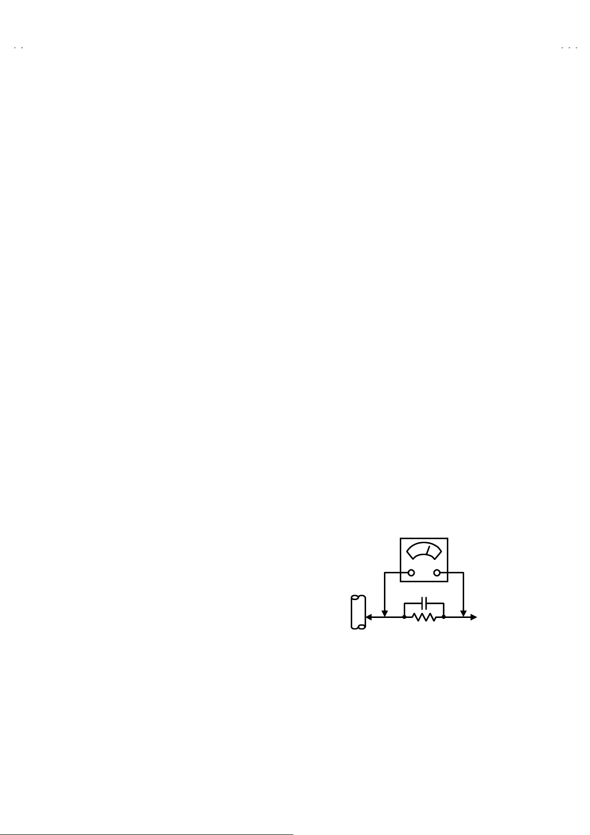
Alternate Check M ethod
zzzz
Plug the AC line cord directly into the AC outlet (do not use a line
isolation transformer during this check. ). Use an AC voltmeter
having 1000 ohms per volt or more sensitivity in the f ollowing
manner. Connect a 1500: 10W resistor paralleled by a 0.15PF
AC-type capacitor between an expos ed metal part and a known
good earth ground (water pipe, etc.). Measure the AC voltage
across the resistor with the AC voltmeter. Move the resistor
connection to each exposed metal part, particularly any exposed
metal part having a return path to the chassis, and measure the
AC voltage across the resist or. Now, reverse the plug in the AC
outlet and repeat each measurement. Any voltage meas ured
must not exceed 0.75V AC (r.m.s.). This corresponds to 0.5mA
AC (r.m.s.).
However, in tr opical area, this must not exc eed 0.3V AC (r.m.s.).
This corresponds to 0.2mA AC (r.m.s.).
AC VOLTMETER
0.15μF AC-T YPE
1500
GOOD EARTH GROUND
:
(HAVING 1000
OR MORE SENSITIVITY)
10W
/V,
:
PLACE THIS PROBE
ON EACH EXPOSED
METAL PART
No.51902
3
Page 4
A
V-21D81
A
A
A
V-20N81
V-16N81
V-16N81G
FEATURES
New chassis design enables use of an interactive on-screen control.
z
Wide range voltage (R ated 110V~240V,Operated 90V~260V) AC power input.
z
With AUDIO / VIDEO INPUT & OUTPUT terminal.
z
MUTING button can reduce the audio level to zero instantly.
z
Functional remote control to operate TV set (for channel select, volume control, power ON/OFF, etc.) from a distance.
z
2
C bus control utilizes single chip ICs for IF, V/C, VSM PRESET.
I
z
By means of AUTO PROGRAM, the TV stations can be s elected automatically and the TV channels can als o be rearranged automatically.
z
Built-in AI ECO (ECONOMY, ECO LOGY) sensor.
z
In accordance with the brightness in a room, the brightness and / or contrast of the picture can be adjust ed automatically to make the
optimum picture which is easy on the eye.
Built - in ON TIMER, RETURN + & CHILD LOCK.
z
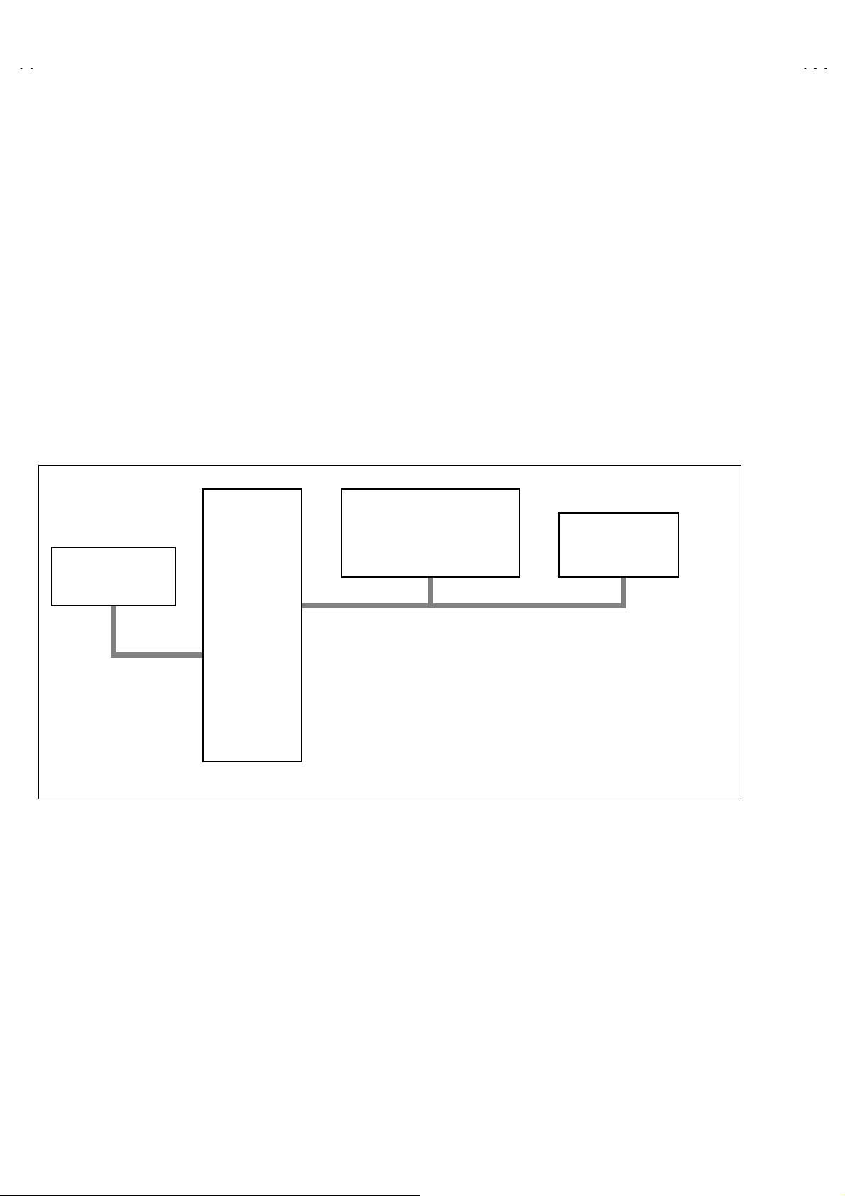
SYSTEM BLOCK DIAGRAM
IC702
MEMORY
SCL2/SDA2
IC701
MICRO
COMPUTER
IC201
VIDEO/CHROMA
DECORDER
SCL1/SDA1
TU001
TUNER
4
No. 51902
Page 5
A
A
A
A
FUNCTIONS
A
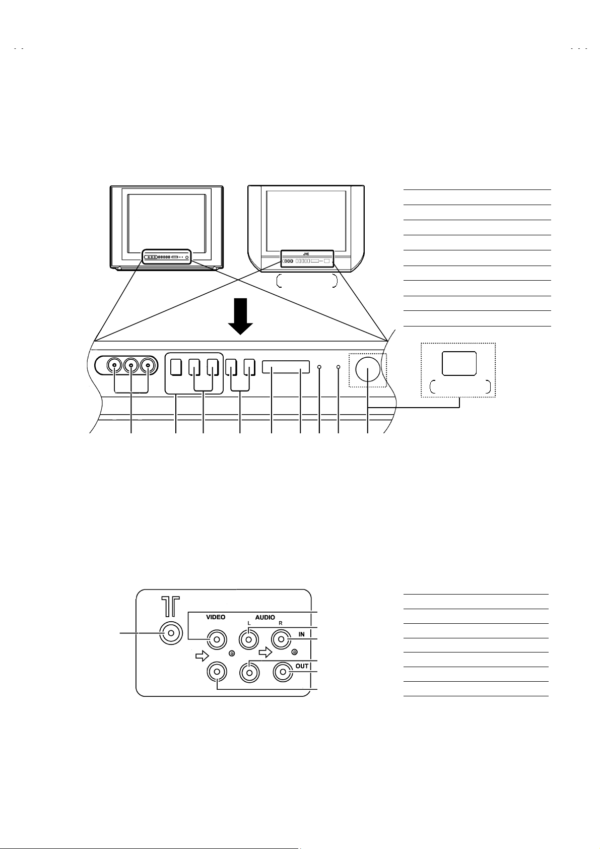
FRONT PANEL
■
( AV-21D81 )
V-20N81
AV-16N81/AV-16N81G
MENU buttons
①
CHANNEL -/+ buttons
②
VOLUME -/+ buttons
③
ECO sensor
④
REMOTE CONTROL sensor
⑤
ON TIMER lamp
⑥
POWER lamp
⑦
MAIN POWER button
⑧
A/V INPUT terminal
⑨
V-21D81
V-20N81
V-16N81
V-16N81G
REAR TERMINAL
■
①
②③④⑤ ⑦⑧⑨① ⑥
②
④
⑤
⑥
⑦
③
AV-20N81
AV-16N81/AV-16N81G
ANT Terminal
①
VIDEO INPUT Terminal
②
VIDEO OUTPUT Terminal
③
AUDIO LEFT INPUT Terminal
④
AUDIO RIGHT INPUT Terminal
⑤
AUDIO LEFT OUTPUT Terminal
⑥
AUDIO RIGHT OUTPUT Terminal
⑦
No. 51902
5
Page 6
A
V-21D81
A
A
A
V-20N81
V-16N81
V-16N81G
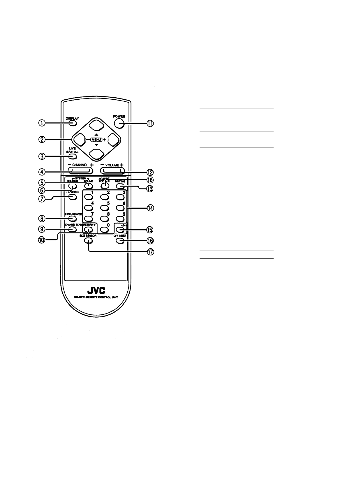
REMOTE CONTROL UNIT(RM-C378)
■
DISPLAY key
①
MENU key
②
MENU ▲/▼ key
MENU -/+ key
LIVE SPATIAL key
③
CHANNEL -/+ key
④
SOUND SYSTEM key
⑤
COLOUR SYSTEM key
⑥
TV / VIDEO key
⑦
PICTURE MODE key
⑧
CHANNEL SCAN key
⑨
RETURN+ key
⑩
POWER key
⑪
VOLUME -/+key
⑫
MUTING key
⑬
NUMBER (CH.) key
⑭
⑮ -/--
⑯
⑰
⑱
key
OFF TIMER key
ECO SENSOR key
PICTURE BOOSTER key
6
No. 51902
Page 7
A
A
A
A
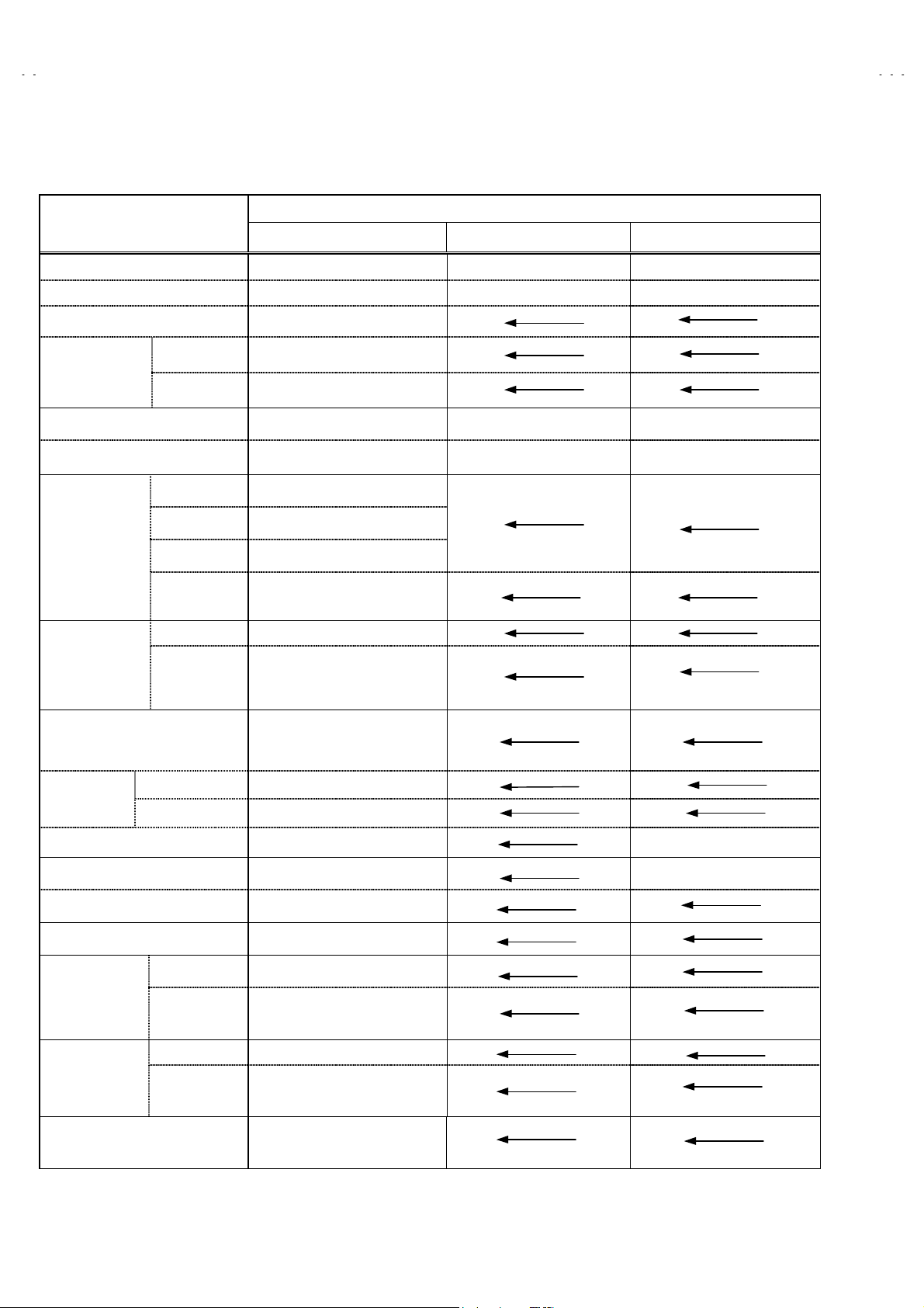
MAIN DIFFERENCE LIST
V-21D81
V-20N81
V-16N81
V-16N81G
Part Name
MAIN PW B SCL-1299A-CK SCL-1295A-CK SCL-1296A-CK
CRT SOCKET PWB SCL-3012A-CK SCL-3013A-CK
FRONT CABINET LC11129- 010A-HK LC10438- 026A-HK GG10021-004A GG10021-005A
POWER KNOB GG30019-001B-H LC30663- 003A-H LC30616- 004A-H
CONTROL KNOB GG20006-001A-H LC20318-003A-H LC20292-004A-H
E.E.WINDOW GG30020-001A-H LC30664- 001B-H LC30617- 001C-H
JVC MARK CM48125-009 CM48006-007-C LC40606-003A
PICTURE TUBE A51JSW 51X07 A48JLL91X01 A38JLL91X13
SPEAKER QAS0032-001 CEBSS12D-04KJ2 CEBSS09D-03KJ2
REAR COVER GG10130-010A-HK LC10448- 001B-HK LC10618- 001A
PACKING CASE GG10007-021A-E GG10007-020A-E GG10007-018A-E GG10007-019A -E
RATING LABEL GG20016-008A-E GG20016-006A-E GG20016-005A-E GG20001-030A-H
Model Name
AV-21D81
/VT
AV-20N81
/VT
AV-16N81
/VT
AV-16N81G
/VT
SERIAL LABEL GG40015-001A-E CM43936-001
Dimension (W×H×D) 598mm×468mm×478mm 619mm×458mm×488mm 518mm×391.5mm×403mm
Mass 21kg 19kg 13kg
Picture T ube
High Voltage 28.0kV±1.0kV 26.5kV±1.0kV 23.0kV±1.0kV
Power Consumption 110W (Max) / 78W (Avg) 89W (Max) / 67W (Avg)
Speaker
Visible size: 51cm
measured diagonally
5cm×12 cm, Oval type×25cm
Visible size: 48cm
measured diagonally
Visible size: 38cm
measured diagonally
9 cm, Oval type×2
×
No. 51902
7
Page 8

A
V-21D81
A
A
A
V-20N81
V-16N81
V-16N81G
SPECIFIC SERVICE INSTRUCTIONS
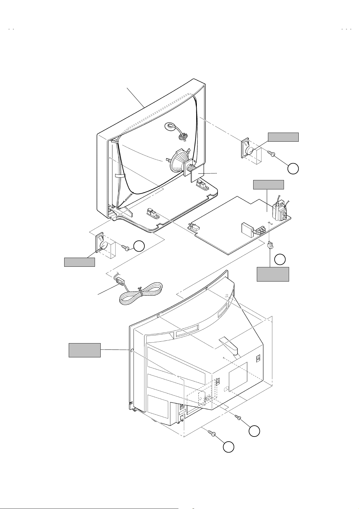
DISASSEMBLY PROCEDURE
REMOVING THE REAR COVER
1. Unplug the power plug.
2. As shown in figure, r emove the
screws marked
2
3. Withdraw the rear cover toward you.
$$$$
.
screws marked
7
REMOVING THE PW BOARD
After removing the rear cover.
z
1. Slightly raise the both sides of the PW BOARD by hand.
and remove the PWB stopper marked
2. W ithdraw the PW BOARD backward.
(If necessary, take off the wire clamp, connectors etc.)
from the front cabinet.
&&&&
REMOVING THE SPEAKER
After removing the rear cover.
z
1. As shown in figure, remove the
2. Follow the s ame steps when removing the other hand speaker.
screws marked
4
%%%%
####
.
and the
CHECKING THE PW BOARD
1. To check the back side of the PW Board.
1) Pull out the PW Board. (Refer to REMOVING THE MAIN PW
Board)
2) Erect the PW Board vertic ally s o that you can easily c heck the
back side of the PW Board.
[CAUTION]
When erecting the PW Board, be careful so that there will be no
z
contac ting with oth er PW Boar d.
Before turning on pow er, make sur e that the CRT earth wire and
z
other connector are properly connected.
WIRE CLAMPING AND CABLE TYING
1. Be sure to clamp the wire.
2. Never remove the c able tie used for tying the wires together.
Should it be inadvertently removed, be sure to tie the wires with a
new cable tie.
8
No. 51902
Page 9
A
A
A
A
■■■■
AV-21D81
FRONT CABI.
CRT SOCKET
PWB
SPEAKER
PW BOARD
C
(×
(×4))))
(×(×
V-21D81
V-20N81
V-16N81
V-16N81G
SPEAKER
POWER
CORD
REAR
COVER
(×
(×4))))
(×(×
C
D
PWB
STOPPER
B
(×
(×2))))
(×(×
A
(×
(×7))))
(×(×
No. 51902
9
Page 10

A
V-21D81
A
A
A
V-20N81
V-16N81
V-16N81G
DISASSEMBLY PROCEDURE
REMOVING THE REAR COVER
1. Unplug the power plug.
2. As shown in figure, r emove the
screws marked
2
3. Withdraw the rear cover toward you.
$$$$
.
screws marked
6
REMOVING THE PW BOARD
After removing the rear cover.
z
1. Slightly raise the both sides of the PW BOARD by hand.
2. W ithdraw the PW BOARD backward.
(If necessary, take off the wire clamp, connectors etc.)
REMOVING THE SPEAKER
After removing the rear cover.
z
1. As shown in figure, remove the
2. Follow the s ame steps when removing the other hand speaker.
screws marked
2
CHECKING THE PW BOARD
1. To check the back side of the PW Board.
1) Pull out the PW Board. (Refer to REMOVING THE MAIN PW
Board)
2) Erect the PW Board vertic ally s o that you can easily c heck the
back side of the PW Board.
[CAUTION]
When erecting the PW Board, be careful so that there will be no
z
contac ting with oth er PW Boar d.
Before turning on pow er, make sur e that the CRT earth wire and
z
other connector are properly connected.
%%%%
####
.
and the
WIRE CLAMPING AND CABLE TYING
1. Be sure to clamp the wire.
2. Never remove the c able tie used for tying the wires together.
Should it be inadvertently removed, be sure to tie the wires with a
new cable tie.
10
No. 51902
Page 11

A
A
A
A
■■■■
AV-20N81
V-21D81
V-20N81
V-16N81
V-16N81G
FRONT CABI.
SPEAKER
SPEAKER
REAR
COVER
C
(
××××
2)
POWER
CORD
CRT SOCKET
PWB
PW BOARD
C
(
2)
××××
(
2)
××××
B
A
(
6)
××××
No. 51902
11
Page 12

A
V-21D81
A
A
A
V-20N81
V-16N81
V-16N81G
DISASSEMBLY PROCEDURE
REMOVING THE REAR COVER
1. Unplug the power plug.
2. As shown in figure, r emove the
screws marked
2
3. Withdraw the rear cover toward you.
$$$$
.
screws marked
5
REMOVING THE PW BOARD
After removing the rear cover.
z
1. Slightly raise the both sides of the PW BOARD by hand.
and remove the PWB stopper marked
2. W ithdraw the PW BOARD backward.
(If necessary, take off the wire clamp, connectors etc.)
from the front cabinet.
&&&&
REMOVING THE SPEAKER
After removing the rear cover.
z
1. As shown in figure, remove the
2. Follow the s ame steps when removing the other hand speaker.
screws marked
4
%%%%
####
.
and the
CHECKING THE PW BOARD
1. To check the back side of the PW Board.
1) Pull out the PW Board. (Refer to REMOVING THE MAIN PW
Board)
2) Erect the PW Board vertic ally s o that you can easily c heck the
back side of the PW Board.
[CAUTION]
When erecting the PW Board, be careful so that there will be no
z
contac ting with oth er PW Boar d.
Before turning on pow er, make sur e that the CRT earth wire and
z
other connector are properly connected.
WIRE CLAMPING AND CABLE TYING
1. Be sure to clamp the wire.
2. Never remove the c able tie used for tying the wires together.
Should it be inadvertently removed, be sure to tie the wires with a
new cable tie.
12
No. 51902
Page 13

A
A
A
A
■■■■
AV-16N81 / AV-16N81G
FRONT CABI.
CRT SOCKET
PWB
SPEAKER
PW BOAR D
V-21D81
V-20N81
V-16N81
V-16N81G
(
4)
××××
C
SPEAKER
REAR
COVER
POWER
CORD
C
(
4)
××××
D
PWB
STOPPER
B
(
2)
××××
(
5)
××××
A
No. 51902
13
Page 14

A
V-21D81
A
A
A
V-20N81
V-16N81
V-16N81G
REPLACEMENT OF MEMORY ICs
1. MEMORY ICs
This model uses memory ICs. This memory IC data are for proper operation of the video and deflection circ uits.
When replacing memory ICs, be sure to use ICs written with the initial values of data.
2. PROCEDURE FOR REPLACING MEMORY ICs
(1) Power off
Switch the power off and disconnect the power plug from the wall outlet.
(2) Replace ICs
Be sure to use memory ICs written with the initial data values.
(3) Power on
Connect the power plug into the wall outlet and switch the power on.
(4) Check and set SYSTEM CONSTANT SET
It must not adjust without adjustment signals.
・・・・
1) Press the
DISPLAY
CONTROL UNIT simultaneously.
2) The SERVICE MENU screen of Fig. 1 will be displayed.
3) While the SERVICE MENU is displayed, again press the
PICTURE MODE
screen of Fig. 2 will be displayed.
4) Check the setting values of the S YSTEM CONSTANT SET of T able 1 If the
value is different, s elect the setting item with the
the correct value with the
5) Press the
DISPLAY
(5) Receive channel of setting
Refer to the
(channels preset) as described
(6) User Setting
Check the user setting value of Table 2, and if setting value is different, set
the correct value.
For setting, refer to the
(7) Setting of SERVICE MENU
Verify the setting items of the SERVICE MENU, and reset where necessary.
For setting, refer to the
key and the
PICTURE MODE
key of the REMOTE
DISPLAY
key simultaneously, and the SYSTEM CONSTANT SET
▼/▲key, and set
MENU
- / + key.
MENU
key twice, and return to the normal screen.
OPERATING INSTRUCTIONS
OPERATING INSTRUCTIONS
SERVICE ADJUSTM ENTS
and set the receive channels
.
.
key and
SERVICE MENU
1.IF 2.V/C
3.VSM PRESET
1-3 SELECT DISP : EXIT
******
***********
***** **
************
**********
*** ** **
*** ** **** ***
*** ** ***** ** **
**.***
****
** ***
** ***** ***
Fig.1
SYSTEM CONSTANT-
SYSTEM CONSTANT SET 1/3
1.INCH : 21
2.COLOUR : MULTI
3.VIDEO INPUT : 1
4.ECO SENSOR : Y ES
5.SUPER BASS : NO
: SELECT
: OPERATE DISP : EXIT
SYSTEM CONSTANT-
SYSTEM CONSTANT SET 2/3
6.SPATIALIZER : YES
7.VOL LIMITER : YES
8.B/B SOUND : NO
9.TEXT : NO
10.COLOUR AUTO : NO
: SELECT
: OPERATE DISP : EXIT
SYSTEM CONSTANT-
***
******
ⅠⅠⅠⅠ
ⅡⅡⅡⅡ
ⅢⅢⅢⅢ
KEY ASSIGNMENT OF REMOTE CONTROL UNIT
SYSTEM CONSTANT SET 3/3
11.LANGUAGE : E/V
12.TUNER : MU
13.AMP TUNER : YES
14.VNR : NO
: SELECT
: OPERATE DISP : EXIT
Fig.2
14
No. 51902
Page 15

A
A
A
A
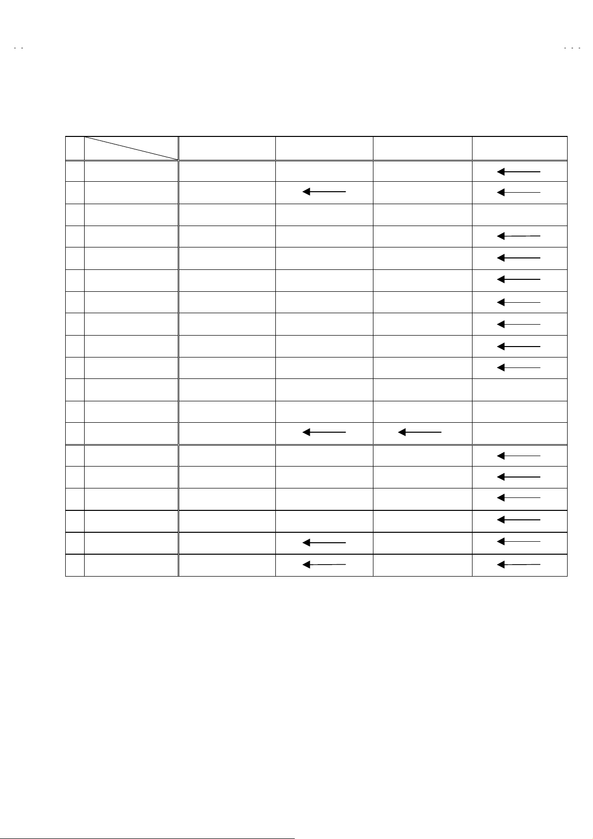
SETTING OF SYSTEM CONSTANT SET
Setting item Setting contents Setting value
V-21D81
V-20N81
V-16N81
V-16N81G
1. INCH
2. COLOUR
3. VIDEO INPUT
4. ECO SENSOR
5. SUPER BASS
6. SPATIALIZER
7. VOL LIMITER
8. B/B SOUND
9. TEXT
10.COLOUR AUTO
11.LANGUAGE
12.TUNER
13.AMP TUNER
14.VNR
21 14 29 25
MULTI
3
1
YES NO
YES NO
YES NO
YES NO
YES NO
YES NO
YES NO
E/V
MU
YES NO
YES
E
MA
NO
21
PALTRIPLE
MULTI
1
YES
NO
YES
YES
NO
NO
NO
E/V
MU
YES
NO
Table 1
USER SETTING VALUES
Setting item Setting value Setting item Setting value
MAIN POWER SW OFF PICTURE MODE (VSM) BRIGHT
SUB POWER ON LANGUAGE VIET
CHANNEL POSITION 1 POSITION CHANNEL PRESET Refer to OPERATING INSTRUCTION
VOLUME
TV/VIDEO
ON SCREEN DISPLAY POSITION INDICATION AUTO SHUTOFF OFF
COLOUR SYSTEM PAL ON TIMER PR1 0:00
SOUND SYSTEM B / G BLUE BACK OFF
OFF TIMER OFF ( shown : 00 ) TREBLE CENTER
LIVE SPATIAL OFF BASS CENTER
CHILD LOCK OFF BALANCE CENTER
PICTURE BOOSTER OFF
About 10 ECO SENSOR OFF
TV VNR OFF
Table 2
No. 51902
15
Page 16

A
V-21D81
A
A
A
V-20N81
V-16N81
V-16N81G
INITIAL SETTING VALUE OF SERVICE MENU
1. Adjustment of the SERVICE MENU is made on the basis of the initial setting values ; however, the new setting values which
set the screen in its optimum condition may differ from the initial setting.
2. Do not change the initial Setting Values of the Setting (Adjustment) items not listed In “ADJUSTMENT”.
2. V/C
Colour system
Setting item
1. CUT OFF
2. DRIVE
3. BRIGHT
4. CONT.
5. COLOUR
6. TINT
7. BLACK OFFSET
8. SHARP
9. TEXT(RGB)CONT.
(Do Not Adj.)
RED
GREEN
BLUE
RED
BLUE
TV
VIDEO
R-Y
B-Y
TV
VIDEO
(Do Not Adj.)
Initial setting value
PAL SECAM NTSC 3.58 NTSC 4.43
+00
+00
+03
-05
+28 +21 +22 -02
+02 -02
+00 +00
+02
-02
+10(AV-21D81)
+05(AV-20N81)
+05(AV-16N81)
+05(AV-16N81G)
+08(AV-21D81)
+03(AV-20N81)
+03(AV-16N81)
+03(AV-16N81G)
+15
10. H CE NTER
11. V HEIGHT
12. V LI N
13. V. S-CR
14. V CENTER
15.AM P T . SHARP
3. VSM PRESET
VSM preset
VSM mode
Setting item
SETTING VALUE +15
TINT
COLOUR
BRIGHT
CONT.
SHARP
SETTING VALUE +15
SETTING VALUE +15
SETTING VALUE +30
SETTING VALUE +15
-10 -08
-04 +04
+02 -04
-40 +20
+00
-15
BRIGHT STANDARD SOFT
+19(AV-21D81/AV-20N81)
+24(AV-16N81/AV-16N81G)
+11(AV-21D81/AV-20N81)
+17(AV-16N81/AV-16N81G)
+12(AV-21D81/AV-20N81)
+10(AV-16N81/AV-16N81G)
16
No. 51902
Page 17

A
A
A
A
SERVICE ADJUSTMENTS
BEFORE STARTING SERVICE ADJUSTMENT
1. There are 2 way of adjusting this TV: One is with t he
REMOTE CONTROL UNIT and the other is the conventional
method using adjustment parts and components.
2. The adjustment with the REMOTE CONTROL UNIT is made
on the basis of the initial setting values. The setting values
which adjust the screen t o its optimum condition may differ
from the initial setting values.
3. Make sure that connection is correctly made to AC power
source.
4. Turn on t he power of the set and equipment before use, and
start the adjustment procedures after waiting at least 30 minutes.
5. Unless otherwise specified, prepare the most suitable rec eption
or input signal for adjustment.
6.
Never touch any adjustment parts, which are not specified
in the list for this adjustment VRs, transforms, cond ensers,
etc.
7. Preparation for adjustment
Unless otherwise specified in the adjustment instructions, preset
the following functions with the REMOTE CONTROL UNIT.
User menu preset value
PICTURE MODE (VSM) BRIGHT
VNR OFF
TINT / COLOUR / BRIGHT /
SHARP / CONT.
BLUE BACK OFF
OFF TIMER OFF
ECO SENSOR OFF
AUTO SHUT OFF OFF
V-21D81
V-20N81
V-16N81
V-16N81G
MENU ITEM PRESET VALUE
CENTER
MEASURING INSTRUMENT AND FIXTURES
1. DC voltmeter (or digital voltmeter)
2. Oscill oscope
3. Signal generator (Pattern generator) [PAL / SECAM / NTSC]
4. Remote c ontrol unit
ADJUSTMENT ITEMS
Adjustment item
B1 POWER SUPPLY V/C (Video / Chroma) circuit adjustment
FOCUS adjustment
IF circuit adjustment PURITY / CONVERGENCE adjustment
VSM PRESET setting
No. 51902
17
Page 18

A
V-21D81
A
A
A
V-20N81
V-16N81
V-16N81G
BASIC OPERATION OF SERVICE MENU
The adju stment using SERVICE MENU
z
The following adjustment items use the SERVICE MENU in the series of the adjustment. The adjustments are made on the basis of the
initial s etting values. The adjustment values which adjust the screen to the optimum c ondition can be diff erent from the initial setting values.
With the SERVICE MENU, various settings c an be made, and they are broadly classified in the following items of s ettings.
1.IF
・・・・・・・・・・・・・・・・・・・・・・・
2.V/C
・・・・・・・・・・・・・・・・・・・・・・
3.VSM PRESET
Key operation of the SERVICE MENU
z
[Enter to SERVICE MENU]
Press the
UNIT simultaneously. Then ent er the SERVICE MENU mode as shown in Fig.1.
DISPLAY
・・・・・・・・・・・・
key and the
Adjustment of the IF circuits.
Adjustment of the VIDEO/CHROMA circuit.
Adjustment of the initial setting values of VSM condition as STANDARD, SOFT and BRIGHT.
(VSM : Video Status Memory)
SERVICE MENU
PICTURE MODE
key of the REMOTE CONTROL
SERVICE MENU
[Exit from SERVICE MENU]
When complete the adjustment work, press the
SERVICE MENU.
And then press the
[Select from SER VICE M ENU]
In SERVICE MENU, press the number (1~3) key of the remote control unit, to select
any of the adjustment items.
[Method of setting]
1. IF
[1. VCO]
1 Key
①
1 Key
②
The VCO (CW ) screen will be displayed a allow mark when
③
the AFC voltage is at a certain level.
DISPLAY Key
④
will return to the
[2. DELAY POINT]
1 Key
①
2 Key
②
MENU -/+
③
DISPLAY Key
④
will return to the
DISPLAY
・・・・・・・・・・・・・・・・・・
・・・・・・・・・・・・・・・・・・
・・・・・・・・・・・・・・・・・・
・・・・・・・・・・・・・・・・・・
・・・・・・・・・・・・・・
key again, return to the nor mal screen.
Select
1.IF
Select
1.VCO
・・・・・・・・・・
・・・・・・・・・・
When this is pressed twic e, you
Select
1.IF
Select
2.DELAY POINT
Set (adjust) the setting values
of the setting items.
When this is pressed twic e, you
DISPLAY
.
SERVICE MENU
.
SERVICE MENU
key to return to the
.
.
.
KEY ASSIGNMENT OF REMOTE CONTROL UNIT
1.IF 2.V/C
3.VSM PRESET
1-3 SELECT DISP : EXIT
******
***********
***** **
************
**********
*** ** **
*** ** **** ***
*** ** ***** ** **
** ***
** ***** ***
Fig.1
**.***
***
****
******
and
2.V/C
①
3. VSM PRESET
②
③
setting items.
④
the
18
3.VSM PRESET
2,3Key
・・・・・・・・・・・・・・・・・
MENU ▼/▲ Key
MENU -/+
DISPLAY Key
・・・・・・・・・・・・・・
・・・・・・・・・・・
・・・・・・・
Select one from
Select s etting items.
Adj us t t he s etting valu es of the
When this is press ed, return to
SERVICE MENU
2. V/C
.
and
.
No. 51902
Page 19

A
A
A
A
SERVICE MENU FLOW CHART
V-21D81
V-20N81
V-16N81
V-16N81G
SERVICE MENU
SERVICE MENU
1.IF 2.V/C
3.VSM PRESET
1-3 SELECT DISP : EXIT
******
***********
***** **
************
**********
*** ** **
*** ** **** ***
*** ** ***** ** **
**.***
****
** ***
** ***** ***
***
******
SUB MENU 1. IF
IF
1. VCO
2. DELAY POINT
1-2 : SELECT DISP : EXIT
SUB MENU 2. V/C
V/C PAL
1. CUTOFF
50Hz
/ :SELECT
- / + : OPERATE DISP : EXIT
(R)
(G)
(B)
***.*
VCO (CW)
TOO HIGH
ABOVE REFERENCE
BELOW REFERENCE
TOO LOW
DELAY POINT UHF
AGC TAKE-OVER
- / + : OPERATE DISP : EXIT
*
MHz
DISP : EXIT
*
*
Setting item
1. CUTOFF
2. DRIVE
* *
*
* *
*
* *
*
3. BRIGHT
4. CONT.
5. COLOUR
6. TINT
7. BLACK OFFSET
8. SHARP
9. TEXT(RGB)CONT.
10. H CENTER
11. V HEIGHT
12. V LIN
13. V. S-CR
14. V CENTER
15. AMP T. SHAR P
(R/G/B)
(R/B)
(P/S/N)
(TV/VI DEO)
(R-Y/B-Y)
(TV/VIDEO)
SUB MENU 3. VSM PRESET
BRIGHT / STD / SOFT
BRIGHT
TINT
COLOUR
BRIGHT
CONT.
SHARP
/ :SELECT
- / + : OPERATE DISP : EXIT
*
*
*
*
*
*
*
*
*
*
SUB VSM
Setting item
TINT
COLOUR
BRIGHT
CONT.
SHARP
No. 51902
19
Page 20

A
V-21D81
A
A
A
V-20N81
V-16N81
V-16N81G
ADJUSTMENT LOCATIONS
TOP
POWER
SW
CRT SOCKET PWB
TP-47G
MAIN PWB
F901
(SOLDER SIDE)
U
TP-47B
TP-E
E1
T
CRT EARTH WIRE
(BRAIDED ASS'Y)
A/V INPUT
FRONT
IC701
DEG
PW
S
TU001
ANT. Terminal
A/V IN&OUTPUT Terminal
IC702
MEMORY IC
IC201
VCO(CW)
T
T101
1Pin TP-91(B1)
2Pin NC
3Pin X-ray1
4Pin X-ray2
5Pin TP-E( )
1
S
HV
U
HVT
UPPER:FOCUS
LOWER:SCREEN
20
No. 51902
Page 21

A
A
A
A
ADJUSTMENTS
B1 POWER SUPPLY
V-21D81
V-20N81
V-16N81
V-16N81G
Item
Check of
B1 Power
Measurin g
instrument
Signal
generator
Supply
DC Voltmeter
FOCUS ADJUSTMENT
Item
Adju stment
of FOCUS
Measurin g
instrument
Signal
generator
IF CIRCUIT ADJUSTMENT
Item
Measurin g
instrument
Test point Adjustment part Description
TP-91 (B1)
TP-E (
)
1. Input a whole black signal.
2. Connect a DC voltmeter to TP-91(B1) and TP-E ().
3. Make sure that the voltage is DC114.5±1.5V.
Test point Adjustment part Description
FOCUS VR
[In HVT]
1. Input a cross-hatch signal.
2. While watching the screen, adjust the FOCUS VR to make the
vertical and horizontal lines as fine and sharp as possible.
3. Make sure t hat when the screen is darkened, the lines r emain in
good focus.
Test point Adjustment part Description
Adju stment
of VCO(CW)
VCO (CW)
TOO HIGH
ABOVE REFERENCE
BELOW REFERENCE
TOO LOW
ADJUSTM ENT AT THI S POINT IS USEL ESS
Signal
Generator
Remote
control unit
V
L
V
L:*****
VLV
L
DISP : EXIT
ADJUSTMENT POI NT
1. VCO
T101
(VCO.TRANSF.)
YELLOW
TOO HIGH
ABOVE REFERENCE
JUST REFERENCE
BELOW REFERENCE
TOO LOW
Please use signal generator which is correct proof about the
●
sending frequency.
1. Input the PAL full c olour bar (210.25MHz) signal.
2. Select 1.IF from the
SERVICE MENU
3. Press 1 key and select
4. T urn the c or e of
VCO (CW) TRANSF. (T101)
1.VCO
.
.
on PW BOARD
5. until the c olour of the characters “TOO HIGH” displayed on the
screen changes from blue to
yellow
.
6. Then slowly turn the core of VCO (CW ) TRANSF.(T101)
counter-clockwise until the colour of the characters “ABOV E
REFERENCE” changes from blue to
yellow
.
7. Further slowly turn the c ore of VCO(CW ) TRANSF.(T101) until
the colour of the characters “BELOW REFERENCE” changes
from blue to
yellow
.
8. Press the DISPLAY key three times to return to normal screen.
No. 51902
21
Page 22

A
V-21D81
A
A
A
V-20N81
V-16N81
V-16N81G
Item
Adju stment
of DELAY
POINT
(AGC)
Measurin g
instrument
Signal
generator
Remote
control unit
DELAY POINT UHF
AGC TAKE-OVER
- / + : OPERATE DISP : EXIT
Test point Adjustment part Description
*
DELAY POINT
(AGC TAKE-OVER)
*
1. Input a black and white signal (colour off).
2. Select
3. Select
control unit.
4. Set the setting values of the setting items as shown bellow table.
5. Then adjust the MENU - or + key until video nois e disappears.
6. Turn to other channels and make sure that there are no
irregularities.
from the SERVICE MENU.
1. IF
2. DELAY POINT
by pressing the 2 key on the remote
Setting Item Variable range Initial setting value
DELAY POINT
(AGC TAKE OVER)
0~127
20
22
No. 51902
Page 23

A
A
A
A
VIDEO / CHROMA CIRCUIT ADJUSTMENT
The setting (adjustment) using the REMOTE CONTROL UNIT is made on the basis of the initial setting values.
The setting values which adju st the screen to the optimum condition can be different from the initial setting values.
Do not change the initial setting values of the setting items not listed in “ADJUSTMENT”.
V-21D81
V-20N81
V-16N81
V-16N81G
Item
Adju stment
of WHITE
BALANCE
(Low light)
Measurin g
instrument
Test point Adjustment part Description
Signal
generator
Remote
control unit
V/C PAL
* *
1. CUTOFF
50Hz
/ :SELECT
- / + : OPERATE DISP : EXIT
(R)
(G)
(B)
*
* *
*
* *
*
KEY ASSIGNMENT OF REMOTE CONTROL UNIT
CUTOFF OFF
(H.LINE OFF)
CUTOFF ON
(H.LINE ON)
R. CUTOFF( )
R. CUTOFF( )
▲
R. DRIVE( )
▲
▼
R. DRIVE( )
▼
123
4
7
R
56
8
9
GB
1. CUT OFF (R)
CUT OFF (G)
CUT OFF (B)
SCREEN VR
[IN HVT]
G.CUTOFF( )
B. CUTOFF( )
B. DRIVE( )
B. CUTOFF( )
B. DRIVE( )
G.CUTOFF( )
▲
▲
▲
▲
▲
▲
1. Input a black and white signal (colour off).
2. Select
(R), (G) and (B) .
OFF
from the SERVICE MENU, then select
2. V/C
1. CUT
3. Set each value to initial setting value with 4~9 keys of the
remote c ontrol unit.
4. Press the
key of the remote control unit to show the single
1
horizontal line on scr een.
5. Turn the
SCREEN VR
fully counter-clockwise, then slowly turn it
clockwis e to where one of a red, blue or green colour is faintly
visible.
6. Use keys
of the remote c ontrol unit and adjust the other 2
4~9
colours which except the appeared c olour to where the single
horizontal line appears white.
7. Turn the
SCREEN VR
to where the single horizontal line glows
faintly.
8. Press the
9. Press the
1. CUT OFF
key to turn off the single horizontal line.
2
DISPLAY
Adjustment item
key twice to return to the normal screen.
Variable
range
-128~+127
R
-128~+127
G
-128~+127
B
Initial setting
value
+00
+00
+00
Adju stment
of WHITE
BALANCE
(High light)
Signal
generator
Remote
control unit
2. DRIVE (R
DRIVE (B)
)
1. Input a black and white signal (colour off).
2. Select
0. Select
from the SERVICE MENU.
2. V/C
2. DRIVE (R) / (B)
with MENU ▼/▲ key, and set each
value to initial setting value with 4 and 7 or 6 and 9 keys of the
remote c ontrol unit.
4. Use the keys
and 7 or 6 and 9 to produce a white screen
4
5. Press the DISPLAY key twice to return to the nomal screen.
V/C PAL
* *
*
2. DRIVE
50Hz
/ :SELECT
- / + : OPERATE DISP : EXIT
(R)
(B)
* *
*
No. 51902
Adjustment item
2. DRIVE
R
B
Variable
range
-128~+127
-128~+127
Initial setting
value
+00
+00
23
Page 24

A
V-21D81
A
A
A
V-20N81
V-16N81
V-16N81G
Item
Adju stment
of
SUB BRIGHT
Adju stment
of
SUB CONT.
Adju stment
of
SUB
COLOUR
ⅠⅠⅠⅠ
Measurin g
instrument
Remote
control unit
Remote
control unit
Remote
control unit
Test point Adjustment part Description
3. BRIGHT
4. CONT.
5. COLOUR [Method of adjustment without measuring instrument]
PAL COLOUR
1. Receive any broadc ast.
2. Select
3. Select
4. Set the initial setting value with the MENU - or + key.
5. If the brightness is not the best with the initial set value, make
fine adjustment until you get the best brightness.
1. Receive any broadc ast.
2. Select
0. Select
4. Set the initial setting value with the MENU - or + key.
5. If the contrast is not the best with the initial set value, make fine
adjustment until you get the best contrast.
1. Receive a PAL broadcast.
2. Select
3. Select
4. Set the initial setting value for PAL COLOUR with the MENU
- or + key.
5. If the colour is not the best with the initial set value, make fine
adjustment until you get the best colour.
from SERVICE MENU.
2. V/C
3. BRIGHT
2. V/C
4. CONT
2. V/C
5. COLOUR
with the MENU ▼/▲key.
from SERVICE MENU.
. with the MENU ▼/▲key.
from the SERVICE MENU.
with the MENU ▼/▲ key.
24
SECAM COLOUR
NTSC 3.58 COLOUR
NTSC 4.43 COLOUR
No. 51902
1. Receive a SECAM broadc ast.
2. Make fine adjustment of SECAM COLOUR as previously.
1. Receive a NTSC 3.58MHz broadc ast.
2. Make similar fine adjustment of NTSC 3.58 COLOUR as
previously.
When NTSC 3.58 adjustment completed, NT SC 4.43 will be
automatically set at the respective values.
Page 25

A
V-21D81
A
A
A
V-20N81
V-16N81
V-16N81G
Item
Adju stment
of SUB
COLOUR
ⅡⅡⅡⅡ
Measurin g
instrument
Signal
generator
Oscilloscope
Remote
control unit
Test point Adjustment part Description
TP-47G
TP-E (
[CRT SOCKET
PWB]
5. COLOUR [Method of adjustment using measuring instrument]
)
PAL COLOUR
1. Input a PAL full field colour bar signal (75% white).
2. Select
3. Select
from SERVICE MENU.
2. V/C
5. COLOUR
with the MENU ▼/▲ key.
4. Set the initial setting value of PAL COLOUR with the MENU
- or + key.
5. Connect the oscillosc ope between TP-47G and TP-E ().
6. Adjust PAL COLOUR to bring the value of
to the values as shown given billow.
(Voltage difference between (W) and (G))
Model Voltage(W-G)
AV-21D81
AV-20N81
AV-16N81
AV-16N81G
/VT
/VT
/VT
/VT
in the illustration
(A)
+5V
+7V
+7V
+7V
SECAM COLOUR
NTSC 3.58 COLOUR
1. Input a SECAM full field colour bar signal (75% white).
2. Set the initial setting value of SECAM COLOUR with the MENU
- or + key.
3. Adjust SECAM COLOUR to bring the value of
(A)
in the
illustration to the values as shown given billow.
Voltage difference between (W) and (G))
Model Voltage(W-G)
AV-21D81
AV-20N81
AV-16N81
AV-16N81G
/VT
/VT
/VT
/VT
+7V
+10V
+13V
+13V
1. Input a NTSC 3.58 full field colour bar signal (75% white).
2. Set the initial setting value of NTSC 3.58 COLOUR with t he
MENU - or + key.
3. Adjust NTSC 3.58 COLOUR to bring the value of
(A)
in the
illustration to the values as shown given billow.
(Voltage difference between (W) and (G))
Model Voltage(W-G)
AV-21D81
AV-20N81
AV-16N81
AV-16N81G
/VT
/VT
/VT
/VT
+5V
+7V
+8V
+8V
NTSC 4.43 COLOUR
When NTSC 3.58 is set, NTSC 4.43 will be automatic ally set at the
respective values.
No. 51902
25
Page 26

A
V-21D81
A
A
A
V-20N81
V-16N81
V-16N81G
Item
Adju stment
of TINT
ⅠⅠⅠⅠ
Adju stment
of TINT
ⅡⅡⅡⅡ
Measurin g
instrument
Signal
generator
Remote
control unit
Signal
generator
Oscilloscope
Remote
control unit
Test point Adjustment part Description
6. TINT [Method of adjustment without measuring instrument]
1. Input a NTSC 3.58 full field colour bar signal (75% white).
2. Select
3. Select
4. Set the initial setting value of NTSC 3.58 with the MENU - or
+ key.
5. If you cannot get the best tint with the initial setting value, make
fine adjustment until you get the best tint.
When NTSC 3.58 is set, NTSC 4.43 will be automatic ally set at the
respective values.
1. Input a NTSC 3.58 full field colour bar signal (75% white).
2. Select
3. Select
4. Set the initial setting value of NTSC 3.58 with the MENU - or
+ key.
5. Connect the oscillosc ope between TP-47G and TP-E. ().
6. Adjust NTSC 3.58 TINT to bring the value of
illustration to the values as shown given billow.
(Voltage difference between (W) and (Cy))
from SERVICE MENU.
2. V/C
with the MENU ▼/▲ key.
6. TINT
from SERVICE MENU.
2. V/C
with the MENU ▼/▲ key.
6. TINT
TP-47G
TP-E (
[CRT
SOCKET
PWB]
NTSC 3.58 TINT
NTSC 4.43 TINT
6. TINT [Method of adjustment using measuring instrument]
)
NTSC 3.58 TINT
(B)
in the
NTSC 4.43 TINT
Model Voltage(W-G)
AV-21D81
AV-20N81
AV-16N81
AV-16N81G
When NTSC 3.58 is set, NTSC 4.43 will be automatic ally set at the
respective values.
/VT
/VT
/VT
/VT
+5V
+7V
+8V
+8V
26
No. 51902
Page 27

A
V-21D81
A
A
A
(
)
)
)
)
V-20N81
V-16N81
V-16N81G
Item
Adju stment
of BLACK
OFFSET
(SECAM)
of BLACK
OFFSET
(SECAM)
ⅠⅠⅠⅠ
KEY ASSIGNMENT OF REMOTE CONTROL UNIT
123
4
789
ⅡⅡⅡⅡ
[R-Y]
Measurin g
instrument
Remote
control unit
56
Signal
generator
Oscilloscope
Remote
control unit
Test point Adjustment part Description
BLACK OFFSET ON
BLACK OFFSET OFF
35 PIN (R-Y)
36 PIN (B-Y)
IC-301 ON
MAIN PWB
(a) (b)
7. BLACK
OFFSET
R-Y (
B-Y (
R-Y
B-Y (
▲
▲
7. BLACK
OFFSET
(R-Y)
(B-Y)
▲
▲
(R-Y)
(B-Y)
***
***
***
***
[Method of adjustment without measuring instrument]
1. Receive a SECAM broadcast.
2. Select 2. V/C from SERVICE MENU.
3. Select 7. BLACK OFFSET with the FUNCTION UP/DOWN key.
4. Set the initial setting value for BLACK OFFSET (R-Y) and (B-Y)
with
and 7 or 6 and 9 keys of the remote c ontrol.
4
5. If the picture is not the best with the initial setting value,
makefine adjustment until you get the best picture.
6. Press the MENU key and memorize the setting value.
[Method of adjustment using measuring instrument]Adju stment
1. Receive a SECAM COLOUR bar s ignal (full field c olour bar
75% white).
2. Select 2. V/C from SERVICE MENU.
3. Select 7. BLACK OFFSET with the FUNCTION UP/DOWN key.
4. Connect the oscilloscope between
().
5. By using
OFFSET (R-Y) so that it bec omes the waveform changes from
(a) to (b) shown in the figure.
6. Connect the oscilloscope between
7. By using
OFFSET (B-Y) s o that it becomes the waveform changes from
(c) to (d) shown in the figure.
8. If the picture is not the best with the adjusted picture, make fine
adjustment until you get the best picture.
9. Press the MENU key and memorize the setting value.
and 7 keys of the remote control, adjust the BLACK
4
and 9 keys of the remote control, adjust the BLACK
6
pin of IC-301 and TP-E
35
pin of IC-301 and TP-E.
36
[B-Y]
(c) (d)
No. 51902
27
Page 28

A
V-21D81
A
A
A
g
V-20N81
V-16N81
V-16N81G
Item
Adju stment
of
V HEIG HT
Screen
size
92%
Measurin g
instrument
Signal
generator
Remote
control unit
Picture size 100%
Test point Adjustment part Description
1. Input a circle pattern signal.
2. Select
3. Select
4. Set the initial setting value with the MENU - / + key.
5. As shown in F ig.1, adjust
screen size
remote c ontrol unit.
from SERVICE MENU.
2.V/ C.
11.V HEIGHT
of the picture size with the MENU - / + keys of
92%
with the MENU ▼/▲ key.
Screen size
Fi
.1
11. V HEIGHT
Picture
size
100%
V HEIGHT
and make the vertic al
Adju stment
of
H CENTER
Signal
generator
Remote
control unit
HH'
Fig.2
10. H CE NTER
6. Input a circle pattern signal.
7. Select
8. Set the initial setting value of
9. Adjust
10. H CENTER
/ + key.
10. H CENTER
the MENU - / + key.
with the MENU ▼/▲ key.
to make
10. H CE NTER
as shown in Fig.2 with
H=H’
with the MENU -
28
No. 51902
Page 29

A
V-21D81
A
A
A
V-20N81
V-16N81
V-16N81G
Item
Adju stment
of V LIN. &
V. S-CR
Measurin g
instrument
Signal
generator
Remote
control unit
Fig.3
Test point Adjustment part Description
When the vertical linearity has been deteriorated
12. V LI N.
13. V. S-CR
TOP
CENTER
BOTTOM
●●●●
remarkably, perform the following steps.
10. Input a cross-hatch signal.
11. Select
12. Set the initial s etting value of
13. Select
14. Set the initial s etting value of
15. Adjust
.
Make sur e that the adjustment is properly done on the screen of
60Hz mode.
[NOTE]
z
z
z
12. V LIN.
key.
13. V. S-CR
key.
12. V LIN.
line as shown in Fig.3 on
become uniform.
Adjust t o make both 50Hz & 60Hz are the same v. size and
fine straight line.
When adjust again, adjust 50Hz mode first.
When adjust in 60Hz mode, only 60H z mode is adjust.
with the MENU ▼/▲ key.
12. V LIN.
with the MENU ▼/▲ key.
13. V. S-CR
and
13. V. S-CR
TOP, CENTER
with the MENU - / +
with the MENU - / +
so that the spaces of each
and
BOTTOM
VSM PRESET SETTING
Item
Setting of
VSM
PRESET
Measurin g
instrument
Remote
control unit
BRIGHT
TINT
COLOUR
BRIGHT
CONT.
SHARP
/ :SELECT
- / + : OPERATE DISP : EXIT
Test point Adjustment part Description
TINT
COLOUR
BRIGHT
CONT.
SHARP
VSM PRESET
xxxx
VSM
*
*
*
*
*
*
*
*
*
*
Setting Item
TINT +15
COLOUR +15
BRIGHT +15
CONT +30
SHARP +15
1. Select
2. Select BRIGHT with the PICTURE MODE key.
3. Adjust the MENU ▼/▲ and MENU - or + key to bring the set
4. Respectively select the VSM PRESET mode for SOFT and
3. VSM PRESET
val ues of
table.
STANDARD, and make similar adjustment as in 3 above.
TINT
BRIGHT STANDARD SOFT
from the SERVICE MENU.
SHARP
~~~~
to the values shown in the below
←
←←
←←
+19(AV-21D81)
+19(AV-20N81)
+24(AV-16N81)
+24(AV-16N81G)
←
←
+11(AV-21D81)
+11(AV-20N81)
+17(AV-16N81)
+17(AV-16N81G)
+12(AV-21D81)
+12(AV-20N81)
+10(AV-16N81)
+10(AV-16N81G)
No. 51902
29
Page 30

A
V-21D81
A
A
A
V-20N81
V-16N81
V-16N81G
PURITY / CONVERGENCE ADJUSTMENT
PURITY ADJUSTMENT
1. Demagnetize CRT with the demagnetizer.
2. Loosen the retainer screw of the deflection yoke.
3. Remove the wedges.
4. Input a green raster signal from the signal generator, and turn
the screen to green raster.
5. Move the deflection yoke backward.
6. Bring the long lug of the pur ity magnets on the short lug and
position them horizontally. (Fig.2)
7. Adjust the gap between two lugs so that the GREEN RASTER
will come into the cent er of the screen. (Fig.3)
8. Move the deflection yoke forward, and fix the position of the
deflection yoke so that the whole screen will become green.
9. Insert the wedge to the top side of the deflection yoke so that it
will not move.
CRT
WEDGE
P : PURITY MAGNET
4 : 4 POLES
6 : 6 POLES
Fig.1
PURITY MAGNETS
DEFLECTION
YOKE
P
46
P / C
MAGNETS
P/C MAGNETS
y
(convergence magnets)
(convergence magnets)
10. Input a crosshatch signal.
11. Verify that the screen is horizontal.
12. Input red and blue raster signals, and make sure that purity is
properly adjusted.
Long lug
Short lug
(FRONT VIEW )
Bring the long lug over the short lug
and position them horizontally.
Fig.2
GREEN RASTER
CENTER
Fig.3
30
No. 51902
Page 31

A
A
A
A
STATIC CONVERGENCE ADJUSTMENT
1. Input a crosshatch signal.
2. Using 4-pole convergenc e magnets, overlap the red and blue
lines in the center of the screen (Fig.1) and turn them to
magenta (red/blue).
3. Using 6-pole convergence magnets, overlap the
magenta(red/blue) and green lines in the center of the screen
and turn them to white.
4. Repeat 2 and 3 above, and make best convergence.
DYNAMIC CONVERGENCE ADJUSTMENT
1. Move the deflection yoke up and down and overlap the lines in
the periphery. (Fig. 2)
2. Move the deflection yoke left to right and overlap the lines in the
periphery. (Fig. 3)
3. Repeat 1 and 2 above, and make best convergence.
(FRONT VIEW )
(FRONT VIEW )
BLUE
GREEN
RED
RED
Fig.1
GREEN
V-21D81
V-20N81
V-16N81
V-16N81G
BLUE
RED
GREEN
BLUE
After adjustment, fix the wedge at the original position.
●
Fast en the r etainer screw of the deflection yoke.
Fix the 6 magnets with glue.
(FRONT VIEW )
GREEN
RED
BLUE
BLUE
GREEN RED
Fig.2
BLUE
Fig.3
GREEN
RED
RED
GREEN
BLUE
BLUE
GREEN
RED
No. 51902
31
Page 32

A
V-21D81
A
A
A
V-20N81
V-16N81
V-16N81G
SELF CHECK FUNCTIONS
1. Outline
This model has self check functions given below. When an abnormality has been detected, the SUB POW ER is turned off and the LED
flashes to inf orm of the failure. An abnormality is detected by the signal input state of the c ontrol line connected t o the microcomputer.
2. Self check items
Check item Details of detection Method of detection State of abnormality
Over-current protection An over-current on the LOW B
line is detected.
The main microcomputer
detects the possible abnormality
at 30-msec. intervals and judges
the results in every 16 time. Of
the 16 times, if NG is detected
more than 9 times, it is judged
that there is an abnormality
When an abnormality has been
detected, the SUB-POWER is
turned off. While the SUBPOWER is being turned off, the
power key of the remote
controller is not operational until
the power code is taken out and
put in again.
CRT NECK protection Operation of Vertical deflection
circuit.
X-ray protection Operation of X-ray pr otection
circuit
3. Self check i ndicating function
At about 3 seconds after the power is turned on, the self-check
function starts.
In the case where an abnormalit y has been detected within the
subsequent 2 seconds, the LED flashes, but the SUB-POW ER
is not turned off.
When an abnormality has been detected at about 5 seconds
after the power is turned on, the SUB POW ER is turned off
immediately and the LED flashes.
[ Indication by LED ]
Item LED flashing intervals Priority of detection
Over-current pr otection Quikly (at about 0.25sec.) intervals 1
①
Power on
DITTO DITTO
DITTO DITTO
After about
3 sec.
Start of
detection
Detection of
an
abnormality
After about
5 sec.
SUBPOW ER
OFF
Flashing LED
CRT NECK protection / X-ray protection
②
Note : In case of ① + ②, the item ① is indic ated
[NOTE]
There are some different types of models with and without X-RAY PROTECTION.
X-RAY :
LED :
There are some kinds of LEDs. In the models equipped wit h LEDs flash (turn on and off) simultaneously. In the models with one
of the above LEDs, the LED flashes.
32
Slowly (at about 0.5s ec.) intervals 2
No. 51902
Page 33

VICTOR COMP ANY OF J APAN, LIMITED
HOME AV NETWORK BUSINESS UNIT 12, 3-chome, Moriya-cho, Kanagawa-ku, Yokohama, Kanagawa-prefecture, 221-8528, Japan
4
AV21D81VT-CK #3 AV20N81VT-CK #3
AV16N81VT-CK #3 AV16N81GVTCK #999
VP 0112
DP7058
 Loading...