

Page 1
52123200305
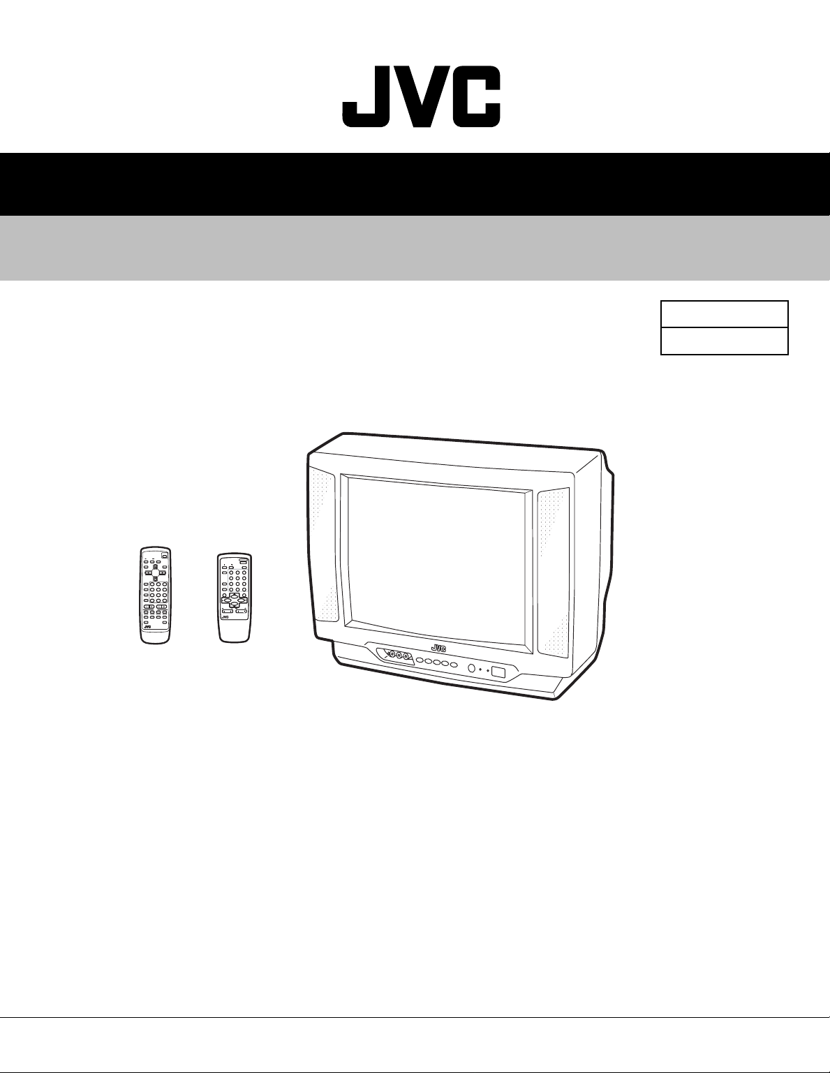
AV-16KG21
AV-16KG11
SERVICE MANUAL
COLOUR TELEVISION
BASIC CHASSIS
AV-16KG21/ Y
CG
AV-16KG11/ Y
POWER
SYSTEM
COLOUR SOUND MUTING
DISPLAY
TV/TEXT
MENU
TV/ VIDEO
123
OFF
TIMER
6
45
PICTURE
MODE
789
CHANNEL
RETURN
SCAN
-/--
0
CHANNEL VOLUME
TEXT
REVEL HOLD INDEX SIZE
CANCEL
SUBPAGE
RM-C91
RM-C91
[AV-16KG21]
POWER
SYSTEM
PICTURE
SOUND
COLOUR
MODE
123
123
TV/VIDEO
456
456
OFF
789
789
TIMER
CHANNEL
RETURN+
-/--
-/--
0
0
SCAN
DISPLAY
MUTING
MENU
CHANNEL
VOLUME
REMOTE CONTROL UNIT
RM-C360GY
RM-C360GY
[AV-16KG11]
TABLE OF CONTENTS
1 PRECAUTIONS . . . . . . . . . . . . . . . . . . . . . . . . . . . . . . . . . . . . . . . . . . . . . . . . . . . . . . . . . . . . . . . . . . . . . . . 1-3
2 SPECIFIC SERVICE INSTRUCTIONS. . . . . . . . . . . . . . . . . . . . . . . . . . . . . . . . . . . . . . . . . . . . . . . . . . . . . . 1-4
3 ADJUSTMENT . . . . . . . . . . . . . . . . . . . . . . . . . . . . . . . . . . . . . . . . . . . . . . . . . . . . . . . . . . . . . . . . . . . . . . . 1-13
COPYRIGHT © 2003 VICTOR COMPANY OF JAPAN, LTD.
No.52123
2003/05
Page 2
AV-16KG21
AV-16KG11
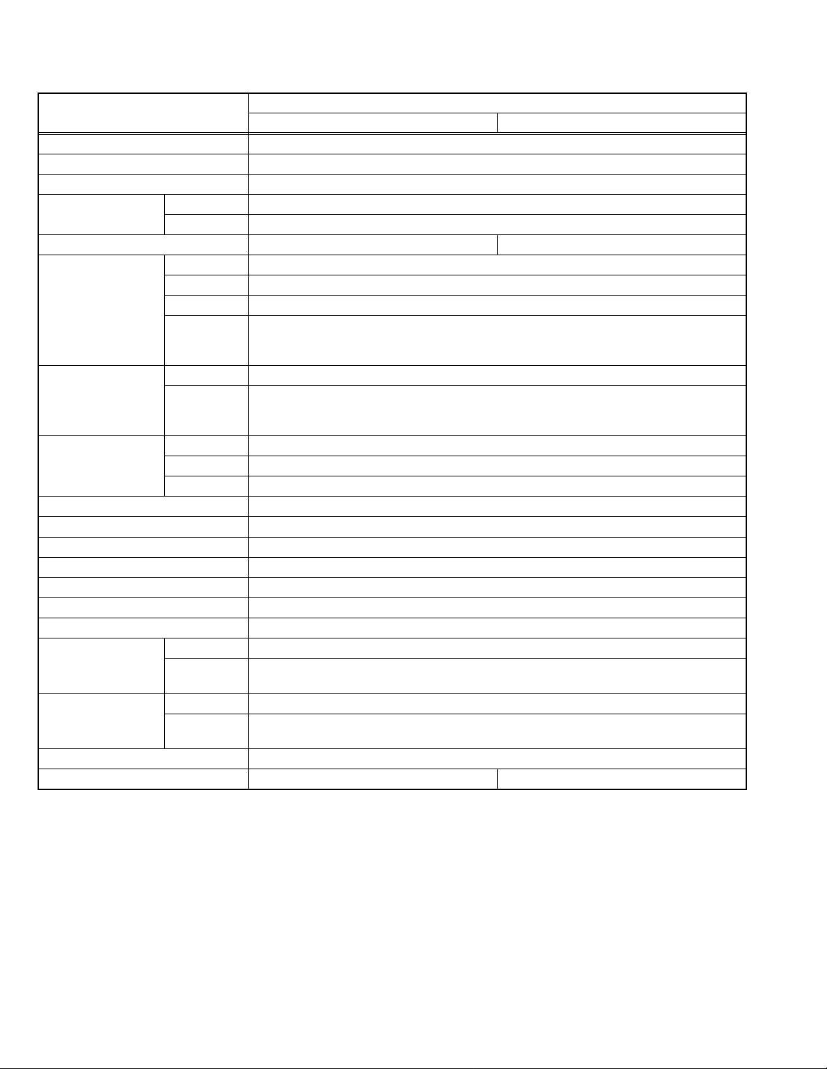
SPECIFICATION
Item
Dimensions (W × H × D) 51.2cm × 38.1cm × 40.3cm
Mass 12.5kg
TV RF System B/G, I, D/K, K1, M
Colour System RF Mode PAL / SECAM / NTSC3.58 / NTSC4.43
VIDEO Mode PAL / SECAM / NTSC3.58 / NTSC4.43
Teletext System FLOF, WST ×
Receiving Frequency VHF (VL) 46.25MHz~140.25MHz
VHF (VH) 147.25MHz~423.25MHz
UHF 431.25MHz~863.25MHz
CATV Mid: X-Z, S1-S10
Super: S11-S20
Hyper: S21-S41
Intermediate
Frequency
Colour Sub Carrier
Frequency
Power Input AC110V~AC240V, 50Hz / 60Hz
Power Consumption 75W (Max) / 55W(Avg)
Picture Tube Visible size: 38cm measured diagonally ( W : 33.2cm × H : 25.1cm)
High Voltage 23.0kV±1.5kV(at zero beam current)
Speaker 5cm × 9cm, Oval type × 2
Audio Power Output 3W (monaural)
Aerial Input Terminal 75Ω unbalanced, coaxial
Input Terminal Video 1V(p-p), 75Ω, RCA pin jack × 2 (Front / Rear)
Output Terminal Video 1V(p-p), 75Ω, RCA pin jack × 1
Headphone Jack 3.5mm mini jack
Remote Control Unit RM-C91 (Battery size : AA / R6 / UM-3 × 2) RM-C360GY (Battery size : AA / R6 / UM-3 × 2)
Design and specifications are subject to change without notice.
VIF Carrier 38.0MHz
SIF Carrier 32.5MHz(5.5MHz) / 33.5MHz (4.5MHz)
31.5MHz (6.5MHz)
32.0MHz (6.0MHz)
PAL 4.43MHz
SECAM 4.40625MHz / 4.25MHz
NTSC 3.58MHz / 4.43MHz
Audio 500mV(rms) (-4dBs), High impedance,
RCA pin jack × 2 (Front) / RCA pin jack × 1 (Rear)
Audio 500mV(rms) (-4dBs), Low impedance,
RCA pin jack × 1
AV-16KG21 AV-16KG11
Content
1-2 (No.52123)
Page 3

SECTION 1
PRECAUTIONS
1.1 SAFETY PRECAUTIONS
(1) The design of this product contains special hardware,
many circuits and components specially for safety
purposes. For continued protection, no changes should be
made to the original design unless authorized in writing by
the manufacturer. Replacement parts must be identical to
those used in the original circuits. Service should be
performed by qualified personnel only.
(2) Alterations of the design or circuitry of the products should
not be made. Any design alterations or additions will void
the manufacturer's warranty and will further relieve the
manufacturer of responsibility for personal injury or
property damage resulting therefrom.
(3) Many electrical and mechanical parts in the products have
special safety-related characteristics. These
characteristics are often not evident from visual inspection
nor can the protection afforded by them necessarily be
obtained by using replacement components rated for
higher voltage, wattage, etc. Replacement parts which
have these special safety characteristics are identified in
the parts list of Service manual. Electrical components
having such features are identified by shading on the
schematics and by ( ) on the parts list in Service
manual. The use of a substitute replacement which does
not have the same safety characteristics as the
recommended replacement part shown in the parts list of
Service manual may cause shock, fire, or other hazards.
(4) Don't short between the LIVE side ground and
ISOLATED (NEUTRAL) side ground or EARTH side
ground when repairing.
Some model's power circuit is partly different in the GND.
The difference of the GND is shown by the LIVE : ( ) side
GND, the ISOLATED (NEUTRAL) : ( ) side GND and
EARTH : ( ) side GND.
Don't short between the LIVE side GND and ISOLATED
(NEUTRAL) side GND or EARTH side GND and never
measure the LIVE side GND and ISOLATED (NEUTRAL)
side GND or EARTH side GND at the same time with a
measuring apparatus (oscilloscope etc.). If above note will
not be kept, a fuse or any parts will be broken.
(5) If any repair has been made to the chassis, it is
recommended that the B1 setting should be checked or
adjusted (See ADJUSTMENT OF B1 POWER SUPPLY).
(6) The high voltage applied to the picture tube must conform
with that specified in Service manual. Excessive high
voltage can cause an increase in X-Ray emission, arcing
and possible component damage, therefore operation
under excessive high voltage conditions should be kept to
a minimum, or should be prevented. If severe arcing
occurs, remove the AC power immediately and determine
the cause by visual inspection (incorrect installation,
cracked or melted high voltage harness, poor soldering,
etc.). To maintain the proper minimum level of soft X-Ray
emission, components in the high voltage circuitry
including the picture tube must be the exact replacements
or alternatives approved by the manufacturer of the
complete product.
(7) Do not check high voltage by drawing an arc. Use a high
voltage meter or a high voltage probe with a VTVM.
Discharge the picture tube before attempting meter
connection, by connecting a clip lead to the ground frame
and connecting the other end of the lead through a 10kΩ
2W resistor to the anode button.
AV-16KG21
AV-16KG11
(8) When service is required, observe the original lead dress.
Extra precaution should be given to assure correct lead
dress in the high voltage circuit area. Where a short circuit
has occurred, those components that indicate evidence of
overheating should be replaced. Always use the
manufacturer's replacement components.
(9) Isolation Check (Safety for Electrical Shock Hazard)
After re-assembling the product, always perform an
isolation check on the exposed metal parts of the cabinet
(antenna terminals, video/audio input and output terminals,
Control knobs, metal cabinet, screw heads, earphone jack,
control shafts, etc.) to be sure the product is safe to operate
without danger of electrical shock.
a) Dielectric Strength Test
The isolation between the AC primary circuit and all metal
parts exposed to the user, particularly any exposed metal
part having a return path to the chassis s hould with stand a
voltage of 3000V AC (r.m.s.) for a period of one second. (.
. . . Withstand a voltage of 1100V AC (r.m.s.) to an
appliance rated up to 120V, and 3000V AC (r.m.s.) to an
appliance rated 200V or more, for a period of one second.)
This method of test requires a test equipment not generally
found in the service trade.
b) Leakage Current Check
Plug the AC line cord directly into the AC outlet (do not use
a line isolation transformer during this check.). Using a
"Leakage Current Tester", measure the leakage current
from each exposed metal part of the cabinet, particularly
any exposed metal part having a return path to the chassis,
to a known good earth ground (water pipe, etc.). Any
leakage current must not exceed 0.5mA AC (r.m.s.).
However, in tropical area, this must not exceed 0.2mA AC
(r.m.s.).
Alternate Check Method
Plug the AC line cord directly into the AC outlet (do not
use a line isolation transformer during this check.). Use
an AC voltmeter having 1000Ω per volt or more
sensitivity in the following manner. Connect a 1500Ω
10W resistor paralleled by a 0.15µF AC-type capacitor
between an exposed metal part and a known good earth
ground (water pipe, etc.). Measure the AC voltage
across the resistor with the AC voltmeter. Move the
resistor connection to each exposed metal part,
particularly any exposed metal part having a return path
to the chassis, and measure the AC voltage across the
resistor. Now, reverse the plug in the AC outlet and
repeat each measurement. Any voltage measured must
not exceed 0.75V AC (r.m.s.). This corresponds to
0.5mA AC (r.m.s.).
However, in tropical area, this must not exceed 0.3V AC
(r.m.s.). This corresponds to 0.2mA AC (r.m.s.).
AC VOLTMETER
(HAVING 1000 /V,
OR MORE SENSITIVITY)
0.15 F AC-TYPE
PLACE THIS PROBE
1500 10W
GOOD EARTH GROUND
ON EACH EXPOSED
METAL PART
(No.52123)1-3
Page 4
AV-16KG21
AV-16KG11
SECTION 2
SPECIFIC SERVICE INSTRUCTIONS
2.1 FEATURES
• New chassis design enables use of an interactive on-screen control.
• Wide range voltage (110V~240V) AC power input.
• With AUDIO / VIDEO INPUT & OUTPUT terminal.
• MUTING button can reduce the audio level to zero instantly.
• Functional remote control to operate TV set (for channel select, volume control, power ON/OFF, etc.) from a distance.
2
C bus control utilizes single chip ICs for IF, V/C, DEF and VSM PRESET.
•I
• The TELETEXT SYSTEM has a built-in FLOF system. (Only for AV-16KG21)
• Built - in ON TIMER, RETURN + & CHILD LOCK.
2.2 MAIN DIFFERENCE LIST
Item AV-16KG21 AV-16KG11
MAIN PWB ASS’Y SCG-1473A-CK SCG-1472A-CK
REMOTE CONTROL UNIT RM-C91-1H RM-C360GY-1H
TELETEXT available ------
1-4 (No.52123)
Page 5
2.3 FUNCTIONS FRONT PANEL
VIDEO
AV-16KG21
AV-16KG11
MENU buttons
1
MENU button
MENU - / + buttons
CHANNEL - / + buttons
2
VOLUME - / + buttons
3
REMOTE CONTROL sensor
4
ON TIMER lamp
JVC
IN
AUDIO
MENU
CHANNEL
VOLUME
EXIT
ON TIMER POWER
5
POWER lamp
6
MAIN POWER button
7
AUDIO INPUT terminal
8
VIDEO INPUT terminal
9
HEADPHONE jack
10
REAR TERMINAL
10
9
1
1 2 3 4 5 6 78
AERIAL terminal
1
VIDEO
AUDIO
2
3
IN
4
OUTPUT
5
VIDEO INPUT terminal
2
AUDIO INPUT terminal
3
4
AUDIO OUTPUT terminal
VIDEO OUTPUT terminal
5
(No.52123)1-5
Page 6
AV-16KG21
AV-16KG11
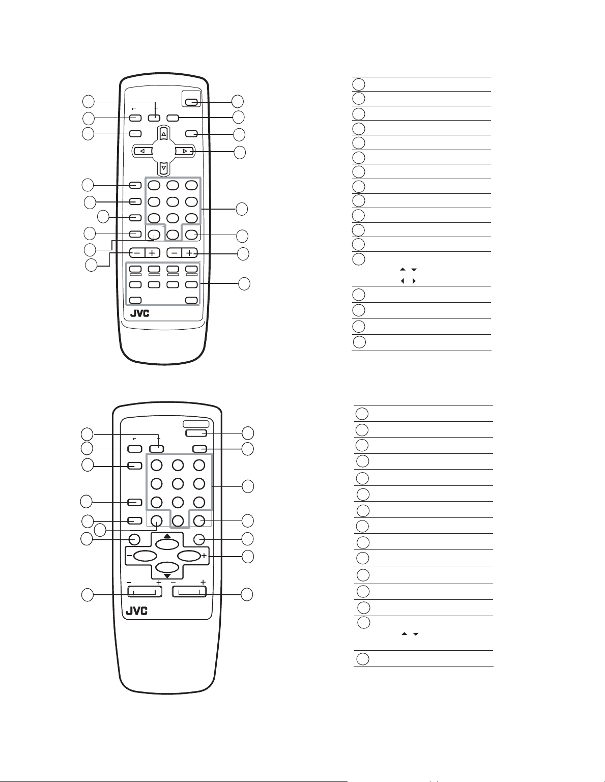
REMOTE CONTROL UNIT
z RM-C91 : AV-16KG21
1
2
3
4
5
7
8
9
COLOUR SOUND MUTING
DISPLAY
TV/ VIDEO
OFF
TIMER
PICTURE
MODE
6
CHANNEL
SCAN
CHANNEL VOLUME
REVEL HOLD INDEX SIZE
SUBPAGE
SYSTEM
MENU
123
45
789
RETURN
0
TEXT
RM-C91
POWER
TV/TEXT
6
-/--
CANCEL
10
10
11
12
13
14
15
16
17
SOUND SYSTEM key
1
2
COLOUR SYSTEM key
DISPLAY key
3
TV/VIDEO key
4
OFF TIMER key
5
PICTURE MODE key
6
CHANNEL SCAN key
7
RETURN + key
8
9
CHANNEL - / + keys
POWERkey
10
MUTINGkey
11
12
TV/TEXTkey
MENU keys
13
MENU / keys
MENU / keys
Number (CH.) keys
14
15
- / - - key
16
VOLUME - / + keys
17
Teletext keys
z RM-C360GY : AV-16KG11
1
2
2
2
2
1
1
1
3
3
3
3
4
4
4
4
5
5
5
5
6
6
6
6
7
7
7
7
8
8
8
8
SYSTEM
COLOUR
TV/VIDEO
OFF
TIMER
CHANNEL
SCAN
DISPLAY
CHANNEL
POWER
SOUND
RETURN+
REMOTE CONTROL UNIT
RM-C360GY
PICTURE
123
123
456
456
789
789
0-/
0-/
MUTING
MENU
VOLUME
MODE
SOUND SYSTEM key
1
COLOUR SYSTEM key
9
9
9
9
10
10
10
10
11
11
--
--
12
12
13
13
14
14
15
15
2
3
TV/VIDEO key
4
OFF TIMER key
CHANNEL SCAN key
5
RETURN + key
6
DISPLAY key
7
CHANNEL - / + keys
8
POWER key
9
PICTURE MODE key
10
Number (CH.) keys
11
12
- / - - key
13
MUTING key
MENU keys
14
MENU / keys
MENU - / + keys
VOLUME - / + keys
15
1-6 (No.52123)
Page 7

2.4 DISASSEMBLY PROCEDURE
2.4.1 REMOVING THE REAR COVER
(1) Unplug the power cord.
(2) Remove the 5 screws [A] and 1 screw [B].
(3) Withdraw the REAR COVER toward you.
2.4.2 REMOVING THE MAIN PW BOARD
• Remove the REAR COVER.
(1) Slightly raise the both sides of the MAIN PW BOARD by
hand and remove the PWB STOPPER under the MAIN PW
BOARD from the FRONT CABINET.
(2) Withdraw the MAIN PW BOARD backward.
(If necessary, take off the wire clamp, connectors etc.)
2.4.3 REMOVING THE SPEAKER
• Remove the REAR COVER.
(1) Remove the 2 screws [C].
(2) Follow the same steps when removing the other hand
SPEAKER.
2.4.4 CHECKING THE MAIN PW BOARD
• To check the back side of the PW BOARD.
(1) Pull out the MAIN PW BOARD. (Refer to REMOVING THE
MAIN PW BOARD)
(2) Erect the PW BOARD vertically so that you can easily
check the back side of the PW BOARD.
CAUTION:
• When erecting the PW BOARD, be careful so that there will
be no contacting with other PW BOARD.
• Before turning on power, make sure that the CRT earth wire
and other connector are properly connected.
AV-16KG21
AV-16KG11
2.4.5 WIRE CLAMPING AND CABLE TYING
(1) Be sure to clamp the wire.
(2) Never remove the cable tie used for tying the wires
together.
Should it be inadvertently removed, be sure to tie the wires
with a new cable tie.
(No.52123)1-7
Page 8
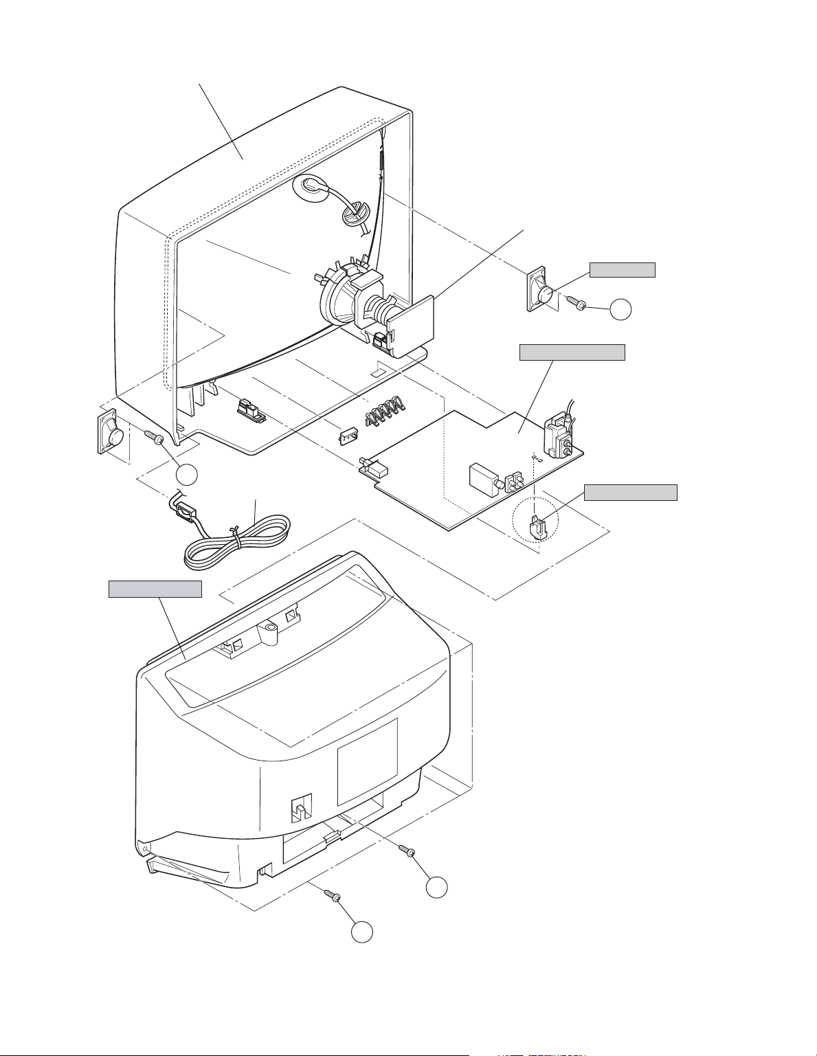
AV-16KG21
AV-16KG11
FRONT CABINET
CRT SOCKET PWB
(Within MAIN PWB)
SPEAKER
MAIN PWB BOARD
C
(x2)
REAR COVER
C
(x2)
POWER CORD
PWB STOPPER
1-8 (No.52123)
B
A
(x5)
Page 9
AV-16KG21
AV-16KG11
2.5 REPLACEMENT OF MEMORY IC
2.5.1 MEMORY IC
This TV use memory IC. In the memory IC, there are memorized data for correctly operating the video and deflection circuits. When
replacing memory IC, be sure to use IC written with the init ial values of data.
2.5.2 PROCEDURE FOR REPLACING MEMORY IC
(1) Power off
Switch the power off and disconnect the power plug from the
wall outlet.
(2) Replace IC
Be sure to use memory IC written with the initial data values.
(3) Power on
Connect the power plug into the wall outlet and switch the
power on.
(4) Check and set SYSTEM CONSTANT SET
• It must not adjust without adjustment signals.
a) Press the [DISPLAY] key and the [PICTURE MODE]
SERVICE MENU
1.IF 2.V/C
3.DEF 4.VSM PRESET
5.PRESET
6.SETUP TOUR OFF
1-6 : SELECT DISP : EXIT
************ **.***
*** ** **** ***
Fig.1
key of the REMOTE CONTROL UNIT simultaneously.
b) The SERVICE MENU screen of Fig. 1 will be
displayed.
c) While the SERVICE MENU is displayed, again press
the [DISPLAY] key and [PICTURE MODE] key
SYSTEM CONSTANT- I
simultaneously, and the SYSTEM CONSTANT SET
screen of Fig. 2 will be displayed.
d) Check th e se ttin g v alue s of the SETTING VALUES OF
SYSTEM CONSTANT SET. If the value is different,
select the setting item with the [MENU /] key, and
set the correct value with the [MENU - / +] key.
e) Press the [DISPLAY] key twice, and return to the
normal screen.
(5) Receive channel of setting
SYSTEM CONSTANT SET 1
COLOUR : MULTI
BILINGUAL : NO
TUNER : MU
ECO SENSOR
LANGUAGE : E/R/A/P
: SELECT
/
- / + : OPERATE DISP : EXIT
: NO
Refer to the OPERATING INSTRUCTIONS and set the
receive channels (channels preset) as described.
SYSTEM CONSTANT- II
(6) User Setting
Check the user setting value and if setting value is different,
set the correct value.
For setting, refer to the OPERATING INSTRUCTIONS.
(7) Setting of SERVICE MENU
Verify the setting items of the SERVICE MENU, and reset
where necessary.
For setting, refer to the ADJUSTMENT.
NOTE:
SYSTEM CONSTANT SET 2
B/B SOUND : OFF
LOCK : 180
COLOUR AUTO
QSS
ALC : NO
TEXT RATE
: SEL - / + : OPE DISP : EXIT
/
: NO
: MINT
: 20
Although the key position of the RM-C91 remote control unit is
different from that of the RM-C360GY remote control unit, the
functions of both units are the same So please use the attached
SYSTEM CONSTANT- III
diagram for the RM-C91 remote control unit for the RM-C360GY.
By the way, [MENU - / +] key functions in the same manner as for
/key.
KEY ASSIGNMENT OF REMOTE CONTROL UNIT
RETURN
POWER
TV/TEXT
MENU
3
2
1
6
5
4
9
8
7
-/--
0
DISPLAY key
MENU
/ key
PICTURE
MODE key
SYSTEM
COLOUR SOUND MUTING
DISPLAY
TV/ VIDEO
OFF
TIMER
PICTURE
MODE
CHANNEL
SCAN
MENU
/ key
NUMBERS
key
(RM-C91)
SYSTEM CONSTANT SET 3
AMP TUNER : NO
VNR
TEXT TABLE : ARA
VOLUME PWM : POS
: SEL - / + : OPE DISP : EXIT
/
: YES
Fig.2
(No.52123)1-9
Page 10
AV-16KG21
AV-16KG11
2.5.3 SETTING VALUES OF SYSTEM CONSTANT SET
Setting item Setting contents Setting value
COLOUR
BILINGUAL
TUNER
AI ECO SENSR
LANGUAGE
B/B SOUND
LOCK
COLOUR AUTO
QSS
ALC
TEXT RATE
AMP TUNER
VNR
TEXT TABLE
VOLUME PWM
MULTI.
YES
MU
YES
E/R/A/P
ON
YES 10 20 ~ 230 240 250
YES
MINT
YES
10 20 40 80
YES
YES
ARA
POS
NO
MA
NO
E/R E/R/U
OFF
NO
MQSS
NO
NO
NO
CYL
NEG
PALTRIPLE
E/C/M/I
MULTI
NO
MU
NO
E/R/A/P
OFF
180
NO
MINT
NO
20
NO
YES
ARA
POS
2.5.4 USER SETTING VALUES
Setting item Setting value Setting item Setting value
SUB POWER ON CHANNEL PRESET Refer to OPERATING INSTRUCTION
CHANNEL POSITION 1 POSITION AI ECO SENSOR OFF
VOLUME About 10 VNR OFF
TV/VIDEO TV AUTO SHUTOFF OFF
COLOUR SYSTEM SECAM ON TIMER PR1 0:00
SOUND SYSTEM B / G BLUE BACK OFF
OFF TIMER 00 CHILD LOCK OFF
PICTURE MODE (VSM) BRIGHT SETUP TOUR ON
LANGUAGE ENGLISH
1-10 (No.52123)
Page 11

2.5.5 SERVICE MENU SETTING ITEMS
Setting item Setting value Setting item Setting value
2. V/C 1.CUT OFF
2.DRIVE
3.BRIGHT
4.CONT.
5.COLOUR
6.TINT
7.SECAM BL ADJ.
8.SHARP
(Do not adjust)
3. DEFLECTION 1. VER. POSITION
2. HOR. POSITION
3. VER. HEIGHT
4. VER. LINEARITY
5. VER. SCURVE
6. HOR. VCO ADJUST
(Do not adjust)
4.VSM PRESET TINT
COLOUR
BRIGHT
CONT.
SHARP
5. PRESET Colour System
(Do not adjust)
Sound System
(Do not adjust)
1. C TRAP FIX
2. SHARP PEAK
3. ABL
4. GAMMA
5. Y. DELAY TIME
6. BLACK EXP START
7. C-BPF
8. CW / SCP
9. VIF DET LEVEL
11. IF AGC MIN
12. VIF AGC
13. VIF PMOD
19. VNR
20. RGB LIM
21. RGB LIMIT LEVEL
23. TEXT H. POSITION
24. READ DATA
10. SIF DET LEVEL
14. SIF BPF BW ADJUST
15. SIF TRAP FO ADJUST
16. SIF TRAP FO ADJUST 2
17. SIF -TRAP
18. SIF -BPF
22. SIF SW
AV-16KG21
AV-16KG11
2.6 REPLACEMENT OF IC301 (IF V/C DECODER)
• For the IC301(IF V/C DECODER) of this model, all data are written in the micro-computer. So, write the data in the micro-
computer in accordance with the following procedures before starting adjustment.
PROCEDURES
(1) Turn the POWER OFF.
(2) Replace the IC301 with a new one.
(3) While pressing MENU button and VOL+ button ON the FRONT CABINET simultaneously, turn the POWER ON. When the
POWER is turned ON, the data is written in the micro-computer immediately.
LOCATIONS OF FRONT PANEL BUTTONS AND LAMPS
MENU buttons
1
MENU button
MENU - / + buttons
-
-
lamp
buttons
MENU
CHANNEL
VOLUME
EXIT
CHANNEL / +
2
VOLUME / + buttons
JVC
ON TIMER POWER
3
REMOTE CONTROL sensor
4
ON TIMER lamp
5
POWER
6
MAIN POWER button
7
1 2 3 4 5 6 7
(No.52123)1-11
Page 12

AV-16KG21
AV-16KG11
2.7 REPLACEMENT OF CHIP COMPONENT
2.7.1 CAUTIONS
(1) Avoid heating for more than 3 seconds.
(2) Do not rub the electrodes and the resist parts of the pattern.
(3) When removing a chip part, melt the solder adequately.
(4) Do not reuse a chip part after removing it.
2.7.2 SOLDERING IRON
(1) Use a high insulation soldering iron with a thin pointed end of it.
(2) A 30w soldering iron is recommended for easily removing parts.
2.7.3 REPLACEMENT STEPS
1. How to remove Chip parts
2. How to install Chip parts
[Resistors, capacitors, etc.]
(1) As shown in the figure, push the part with tweezers and
alternately melt the solder at each end.
(2) Shift with the tweezers and remove the chip part.
[Transistors, diodes, variable resistors, etc.]
(1) Apply extra solder to each lead.
SOLDER
SOLDER
[Resistors, capacitors, etc.]
(1) Apply solder to the pattern as indicated in the figure.
(2) Grasp the chip part with tweezers and place it on the
solder. Then heat and melt the solder at both ends of the
chip part.
[Transistors, diodes, variable resistors, etc.]
(1) Apply solder to the pattern as indicated in the figure.
(2) Grasp the chip part with tweezers and place it on the
solder.
(3) First solder lead A as indicated in the figure.
(2) As shown in the figure, push the part with tweezers and
alternately melt the solder at each lead. Shift and remove
the chip part.
NOTE :
After removing the part, remove remaining solder from the
pattern.
1-12 (No.52123)
A
B
C
(4) Then solder leads B and C.
A
B
C
Page 13

AV-16KG21
AV-16KG11
SECTION 3
ADJUSTMENT
3.1 ADJUSTMENT PREPARATION
(1) There are 2 ways of adjusting this TV : One is with the REMOTE CONTROL UNIT and the other is the conventional method
using adjustment parts and components.
(2) The adjustment using the REMOTE CONTROL UNIT is made on the basis of the initial setting values. The setting values which
adjust the screen to the optimum condition can be different from the initial setting values.
(3) Make sure that connection is correctly made AC to AC power source.
(4) Turn on the power of the TV and measuring instruments for warning up for at least 30 minutes before starting adjustments.
(5) If the receive or input signal is not specified, use the most app ropriate signal for adjustment.
(6) Never touch the parts (such as variable resistors, transformers and condensers) not shown in the adjustment items of this service
adjustment.
(7) Preparation for adjustment.
Unless otherwise specified in the adjustment items, preset the following functions with the REMOTE CONTROL UNIT.
Item Preset value
PICTURE MODE (VSM) STANDARD
TINT / COLOUR / BRIGHT / CONT. / SHARP Center
VNR OFF
AI ECO SENSOR OFF
BLUE BACK OFF
OFF TIMER OFF
AUTO SHUT OFF OFF
3.2 MEASURING INSTRUMENT AND FIXTURES
(1) DC voltmeter (or digital voltmeter)
(2) Oscilloscope
(3) Signal generator (Pattern generator : PAL / SECAM / NTSC)
(4) Remote control unit
3.3 ADJUSTMENT ITEMS
• B1 POWER SUPPLY
• FOCUS ADJUSTMENT
• IF CIRCUIT ADJUSTMENT
• VIDEO/CHROMA CIRCUIT ADJUSTMENT
• DEFLECTION CIRCUIT ADJUSTMENT
• VSM PRESET SETTING
• PURITY/ CONVERGENCE ADJUSTMENT
(No.52123)1-13
Page 14

AV-16KG21
AV-16KG11
3.4 ADJUSTMENT LOCATIONS
TOP
MAIN PWB
F901
CRT SOCKET PWB
TP-47R/G
T
IC701
(SOLDER SIDE)
U
TP-47B
TP-E
E1
CRT EARTH WIRE
(BRAIDED ASS'Y)
IC702
MEMORY IC
FRONT
PW
DEG
IC821
S
[Only for AV-16KG21]
IC301
S1
HV
TU001
T
U
HVT
1Pin TP-91(B1)
2Pin NC
UPPER:FOCUS
LOWER:SCREEN
3Pin X-ray1
4Pin X-ray2
5Pin TP-E( )
1-14 (No.52123)
Page 15

3.5 BASIC OPERATION OF SERVICE MENU
3.5.1 TOOL OF SERVICE MENU OPERATION
Operate the SERVICE MENU with the REMOTE CONTROL UNIT.
3.5.2 SERVICE MENU ITEMS
With the SERVICE MENU, various adjustments can be made, and they are broadly classified in the following items of settings.
1.IF Adjustment of the IF circuits.
2.V/C Adjustment of the VIDEO/CHROMA circuit.
3.DEF Adjustment of the DEFLECTION circuit.
4.VSM PRESET Adjustment of the initial setting values of VSM condition as STANDARD SOFT and BRIGHT.
(VSM : Video Status Memory)
5.PRESET Adjustment of the RF circuit (Do not adjust).
6.SETUP TOUR OFF It should be able to select mode (LANGUAGE and AUTO CH PRESET) [Should be OFF].
3.5.3 BASIC OPERATION IN SERVICE MENU
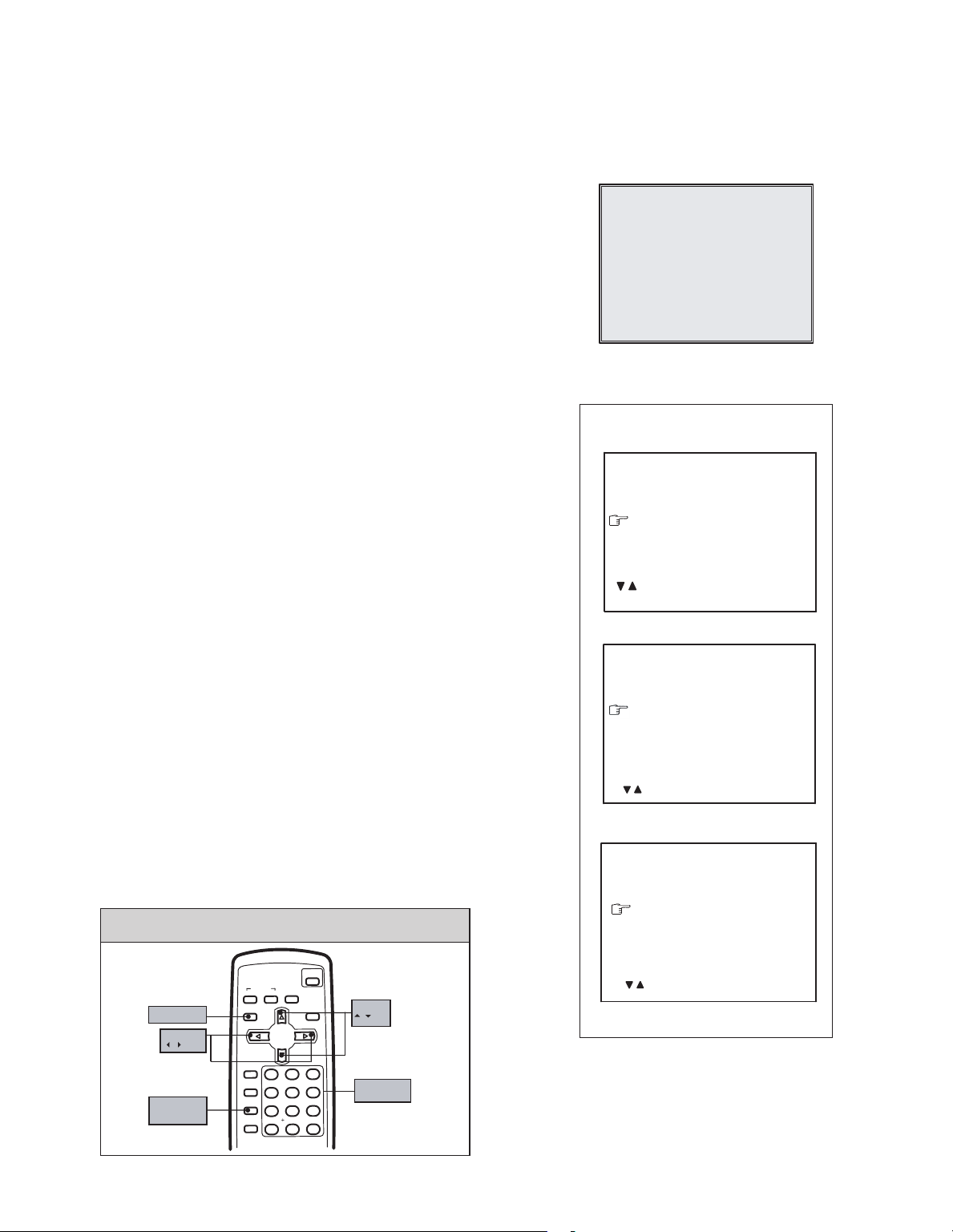
[Enter to SERVICE MENU]
Press the DISPLAY key and the PICTURE MODE key of the
REMOTE CONTROL UNIT simultaneously. Then enter the
SERVICE MENU mode as shown in Fig.1.
SERVICE MENU
1.IF 2.V/C
3.DEF 4.VSM PRESET
5.PRESET
6.SETUP TOUR OFF
1-6 : SELECT DISP : EXIT
************ **.***
*** ** **** ***
Fig.1
AV-16KG21
AV-16KG11
[Exit from SERVICE MENU]
When complete the adjustment work, press the [DISPLAY] key to return to the SERVICE MENU.
And then press the DISPLAY key again, return to the normal screen.
[Select from SERVICE MENU]
In SERVICE MENU, press the number [1]~[6] keys of the remote control unit, to select any of the adjustment items.
The colours which selected item characters are changed.
KEY ASSIGNMENT OF REMOTE CONTROL UNIT
POWER
SYSTEM
COLOUR SOUND MUTING
DISPLAY key
MENU
/ key
PICTURE
MODE key
DISPLAY
TV/ VIDEO
123
OFF
TIMER
456
PICTURE
MODE
789
CHANNEL
RETURN
SCAN
CHANNEL VOLUME
REVEL HOLD INDEX SIZE
MENU
TEXT
TV/TEXT
0
-/--
MENU
/ key
NUMBERS
key
(RM-C91)
KEY ASSIGNMENT OF REMOTE CONTROL UNIT
POWER
DISPLAY key
MENU
- / + key
SYSTEM
COLOUR
TV/VIDEO
OFF
TIMER
CHANNEL
SCAN
DISPLAY
CHANNEL
SOUND
RETURN
MENU
MENU
PICTURE
MODE
123
456
789
+
0-/
MUTING
VOLUME
--
PICTURE
ey
MODE k
NUMBERS
key
MENU
/ key
(RM-C360GY)
(No.52123)1-15
Page 16

AV-16KG21
************ **.***
AV-16KG11
3.5.4 SERVICE MENU FLOW CHART
SERVICE MENU
SERVICE MENU
1.IF 2.V/C
3.DEF 4.VSM PRESET
5.PRESET
6.SETUP TOUR OFF
1-6 : SELECT DISP : EXIT
************ **.***
*** ** **** ***
6. SETUP TOUR OFF
(By pressing [6] key)
ON / OFF
SUB MENU 1. IF
IF
1. VCO
2. DELAY POINT
1-2 : SELECT DISP : EXIT
SUB MENU 2. V/C
V/C PAL
1. CUTOFF
(G)
(B)
50Hz
/ : SELECT
- / + : OPERATE DISP : EXIT
(R)
* **
* **
* **
SUB MENU 3. DEF
VCO (CW)
TOO HIGH
ABOVE REFERENCE
JUST REFERENCE
BELOW REFERENCE
TOO LOW
AFT ADJUST
VCO ADJUST
FINE
DISP : EXIT
DELAY POINT UHF
AGC TAKE-OVER
- / + : OPERATE DISP : EXIT
***.**
MHz
*** (**
*** (**
**
)
)
DEF PAL
1. VER. POSITION
50Hz
/ : SELECT
- / + : OPERATE DISP : EXIT
**
SUB MENU 4. VSM PRESET
BRIGHT
TINT
COLOUR
BRIGHT
CONT.
SHARP
/ : SELECT
- / + : OPERATE DISP : EXIT
**
**
**
**
**
SUB MENU 5. PRESET
PRESET PAL
1. C-TRAP FIX
50Hz B/G
/ : SELECT
- / + : OPERATE DISP : EXIT
*
1-16 (No.52123)
Page 17

3.5.5 METHOD OF SETTING
1. IF
[1. VCO]
(1) [1] key Select 1. IF.
(2) [1] key Select 1. VCO.
(3) The VCO (CW) screen will be displayed a allow mark when the AFT voltage is at a certain level.
(4) [DISPLAY] key As you press this key twice, you will return to the SERVICE MENU.
[2. DELAY POINT]
(1) [1] key Select 1. IF.
(2) [2] key Select 2. DELAY POINT.
(3) [MENU - / +] keys Set (adjust) the setting values of the setting items.
(4) [DISPLAY] key When this is pressed twice, you will return to the SERVICE MENU.
NOTE:
When the setting value has been changed, the new value will be stored in memory immediately.
2. V/C, 3. DEF and 4. VSM PRESET
(1) [2]~[4] keys Select one from 2. V/C, 3. DEF and 4. VSM PRESET.
(2) [MENU /] keys Select setting items.
(3) [MENU - / +] keys Adjust the values of the items.
(4) [DISPLAY] key When this is pressed, return to the SERVICE MENU.
NOTE:
When the setting value has been changed, the new value will be stored in memory immediately.
AV-16KG21
AV-16KG11
6. SETUP TOUR
(1) By pressing the [6] key, you can change the ON or OFF (should be OFF).
(Should be OFF)
If it is ON, then you turn the TV power off, when you are turn the TV power on again.
The JVC's logo will be shown about 15 seconds automatically.
(2) [MENU - / +] keys Select Language.
(3) [MENU ] key Auto Search.
(No.52123)1-17
Page 18

AV-16KG21
AV-16KG11
3.6 INITIAL SETTING VALUE OF SERVICE MENU
• Adjustment of the SERVICE MENU is made on the basis of the initial setting values ; however , the new setting values which
set the screen in its optimum condition may differ from the initial setting.
• Do not change the initial Setting Values of the Setting (Adjustment) items not listed in "ADJUSTMENT PROCEDURE".
2. V/C
Setting item Variable range
1.CUT OFF RED -128 ~ +127 -50 ←←←
GREEN ←←←
BLUE ←←←
2.DRIVE RED -128 ~ +127 0 ←←←
BLUE ←←←
3.BRIGHT -128 ~ +127 0 ←←←
4.CONT. -64 ~ +63 0 ←←←
5.COLOUR -64 ~ +63 0 ←←←
6.TINT TV -64 ~ +63 - - 0 0
VIDEO - - +8 0
7.SECAM BL ADJ. -32 ~ +31 0 ←←←
8.SHARP
(Do not adjust)
3. DEFLECTION
1. VER. POSITION -04 ~ +03 -2 -3
2. HOR. POSITION -16 ~ +15 +1 +3
3. VER. HEIGHT -64 ~ +63 +25 -5
4. VER. LINEARITY -32 ~ +31 +15 -5
5. VER. SCURVE -32 ~ +31 -31 +15
6. HOR. VCO ADJUST
(Do not adjust)
TV -32 ~ +31 -8 (Fixed) ←←←
VIDEO +15 (Fixed)
Setting item Variable range
-64 ~ +63 0 0
PAL SECAM NTSC 3.58 NTSC 4.43
Initial setting value
Initial setting value
fv : 50Hz fv : 60Hz
4.VSM PRESET
Setting item
TINT +15 ←←
COLOUR +15 ←←
BRIGHT +15 ←←
CONT. +30 +15 +11
SHARP +15 ← +12
1-18 (No.52123)
BRIGHT STANDARD SOFT
Initial setting value
Page 19

AV-16KG21
AV-16KG11
5. PRESET
The items in the following table, it is no requirement for adjustment.
If values had changed by the miss operation, set the initial setting values in the following table.
z COLOR SYSTEM (Do not adjust)
Setting item
1. C TRAP FIX 1 1 1 1
2. SHARP PEAK 0 0 0 0
3. ABL 1111
4. GAMMA 0 0 0 0
5. Y. DELAY TIME TV 0 2 2 3
VIDEO 0 2 0 2
6. BLACK EXP START +3 +3 +3 +3
7. C-BPF TV 1 1 0 0
VIDEO 1 1 1 1
8. CW / SCP 0 0 0 0
9. VIF DET LEVEL 0 0 0 0
11. IF AGC MIN 0 0 0 0
12. VIF AGC 0 0 0 0
13. VIF PMOD 0000
19. VNR 15 15 15 15
20. RGB LIM 1 1 1 1
21. RGB LIMIT LEVEL 2 2 2 2
23. TEXT H. POSITION -3 -3 -3 -3
24. READ DATA - - - -
PAL SECAM NTSC 3.58 NTSC 4.43
Initial setting value (Fixed value)
z SOUND SYSTEM (Do not adjust)
Setting item
10. SIF DET LEVEL +0 +0 +0 +0
14. SIF BPF BW ADJUST +0 +0 +0 +0
15. SIF TRAP FO ADJUST +0 +0 +0 +0
16. SIF TRAP FO ADJUST 2 +0 +0 +0 +0
17. SIF -TRAP 0 0 0 0
18. SIF -BPF 0 0 0 1
22. SIF SW 1 1 1 0
B/G I D/K M
Initial setting value (Fixed value)
(No.52123)1-19
Page 20

AV-16KG21
AV-16KG11
3.7 ADJUSTMENT PROCEDURE
3.7.1 B1 POWER SUPPLY
Item
B1 POWER
SUPPLY
Measuring
instrument
Signal
generator
check
DC voltmeter
3.7.2 FOCUS ADJUSTMENT
Item
Measuring
instrument
FOCUS Signal
generator
3.7.3 IF CIRCUIT ADJUSTMENT
Item
Measuring
instrument
IF VCO Signal
generator
Remote
control unit
VCO (CW)
TOO HIGH
ABOVE REFERENCE
JUST REFERENCE
BELOW REFERENCE
TOO LOW
AFT ADJUST
VCO ADJUST
FINE
DISP : EXIT
***.**
Test point Adjustment part Description
TP-91(B1)
TP-E( )
(1) Receive a whole black signal.
(2) Connect a DC voltmeter to TP-91(B1) and TP-E ( ).
(3) Make sure that the voltage is DC116.2V±2.0V.
Test point Adjustment part Description
FOCUS VR
[In HVT]
(1) Receive a cross-hatch signal.
(2) While watching the screen, adjust the FOCUS VR to
make the vertical and horizontal lines as fine and
sharp as possible.
(3) Make sure that when the screen is darkened, the
lines remain in good focus.
Test point Adjustment part Description
[1. IF]
1. VCO
• Please use signal generator which is correct proof about
the sending frequency.
(1) Receive a PAL full colour bar (210.25MHz) signal.
(2) Select 1.IF.
(3) Select < 1.VCO >.
(4) Select VCO ADJUST.
MHz
(5) Press [MENU - / +] keys until the colour of the
characters TOO HIGH changes blue to yellow. Then
gradually press the [MENU - / +] keys until the TOO
YELLOW
LOW changes yellow. At this time, confirm that the
value of VCO ADJUST is near +00.
***(**
***(**
)
)
(6) Select AFT ADJUST.
(7) Press [MENU - / +] keys until the characters JUST
REFERENCE changes blue to yellow.
(8) Press the [DISPLAY] key three times to return to
normal screen.
ADJUSTMENT AT THIS POINT
IS USELESS
1-20 (No.52123)
TOO HIGH
ABOVE REFERENCE
JUST REFERENCE
BELOW REFERENCE
TOO LOW
ADJUSTMENT POINT
Page 21

AV-16KG21
AV-16KG11
Item
DELAY POINT
(AGC)
Setting item
DELAY POINT
(AGC TAKE-OVER)
Measuring
instrument
Test point Adjustment part Description
Signal
generator
Remote
control unit
DELAY POINT UHF
AGC TAKE-OVER **
- / + : OPERATE DISP : EXIT
Variable range
NTSC3.58
OTHER
0 ~ 127
[1. IF]
2. DELAY POINT
(AGC TAKE-OVER)
Initial setting value
47
35
(1) Receive a black and white signal (colour off).
(2) Select 1. IF.
(3) Select < 2. DELAY POINT >.
(4) Set the setting values of the setting items as shown
bellow table.
(5) Then adjust the [MENU - / +] keys until video noise
disappears.
(6) Turn to other channels and make sure that there are
no irregularities.
(No.52123)1-21
Page 22

AV-16KG21
AV-16KG11
3.7.4 VIDEO / CHROMA CIRCUIT ADJUSTMENT
The setting (adjustment) using the REMOTE CONTROL UNIT is made on the basis of the initial setting values.
The setting values which adjust the screen to the optimum condition can be different from the initial setting values.
Do not change the initial setting values of the setting items not listed in "ADJUSTMENT PROCEDURE".
Item
WHITE
BALANCE
(LOW LIGHT)
Measuring
instrument
Signal
generator
Remote
control unit
Test point Adjustment part Description
[2.V/C]
1. CUT OFF (R)
1. CUT OFF (G)
1. CUT OFF (B)
(1) Receive a black and white signal (colour off).
(2) Select 2. V/C.
(3) Select < 1. CUT OFF> .
(4) Set each value to initial setting value with [4]~[9]
keys.
SCREEN VR
[IN HVT]
(5) Press the [1] key to show the single horizontal line on
screen.
(6) Turn the SCREEN VR fully counter-clockwise, then
slowly turn it clockwise to where one of a red, blue or
V/C PAL
1. CUTOFF
(G) * **
(B) * **
50Hz
/ : SELECT
- / + : OPERATE DISP : EXIT
(R) * **
green colour is faintly visible.
(7) Use [4]~[9] keys and adjust the other 2 colours which
except the appeared colour to where the single
horizontal line appears white.
(8) Turn the SCREEN VR to where the single horizontal
line glows faintly.
(9) Press the [2] key to turn off the single horizontal line.
(10) Press the [DISPLAY] key twice to return to the
normal screen.
CUTOFF OFF
(H.LINE OFF)
CUTOFF ON
(H.LINE ON)
R. CUTOFF( )
R. DRIVE( )
R. CUTOFF( )
R. DRIVE( )
WHITE
BALANCE
(HIGH LIGHT)
KEY ASSIGNMENT OF REMOTE CONTROL UNIT
123
456
789
G.CUTOFF( )
B. CUTOFF( )
B. DRIVE( )
B. CUTOFF( )
B. DRIVE( )
G.CUTOFF( )
R G B
Signal
generator
Remote
control unit
V/C PAL
2. DRIVE (R) * **
(B) * **
50Hz
/ : SELECT
- / + : OPERATE DISP : EXIT
[2.V/C]
2. DRIVE (R)
2. DRIVE (B)
Adjustment item
1.CUT OFF
R
G
B
Variable
range
-128 +127
-128 +127
-128 +127
Initial setting
value
-50
-50
-50
(1) Receive a black and white signal (colour off).
(2) Select 2. V/C.
(3) Select < 2. DRIVE> .
(4) Set each value to initial setting value with [4] and [7]
or [6] and [9] keys.
(5) Use the [4] and [7] or [6] and [9] keys to produce a
white screen.
(6) Press the [DISPLAY] key twice to return to the nomal
screen.
Adjustment item
2.DRIVE
R
B
Variable
range
-128 +127
-128 +127
Initial setting
value
+0
+0
1-22 (No.52123)
Page 23

AV-16KG21
AV-16KG11
Item
Measuring
instrument
SUB BRIGHT Remote
control unit
SUB
CONTRAST
Remote
control unit
SUB COLOUR I Remote
control unit
Test point Adjustment part Description
[2. V/C]
3. BRIGHT
(1) Receive any broadcast.
(2) Select 2. V/C.
(3) Select < 3. BRIGHT > .
(4) Set the initial setting value with the [MENU - / +] key.
(5) If the brightness is not the best with the initial set
value, make fine adjustment until you get the best
brightness.
[2. V/C]
4. CONT.
(1) Receive any broadcast.
(2) Select 2. V/C.
(3) Select < 4. CONT >.
(4) Set the initial setting value with the [MENU - / +] key.
(5) If the contrast is not the best with the initial set value,
make fine adjustment until you get the best contrast.
[2. V/C]
5. COLOUR
(PAL/SECAM/NTSC)
[Method of adjustment without measuring instrument]
PAL COLOUR :
(1) Receive a PAL broadcast.
(2) Select 2. V/C.
(3) Select < 5. COLOUR >.
(4) Set the initial setting value for PAL COLOUR with the
[MENU - / +] key.
(5) If the colour is not the best with the initial set value,
make fine adjustment until you get the best colour.
SECAM COLOUR :
(1) Receive a SECAM broadcast.
(2) Make fine adjustment of SECAM COLOUR as
previously.
NTSC 3.58 COLOUR :
(1) Recsive a NTSC 3.58MHz broadcast.
(2) Make similar fine adjustment of NTSC 3.58
COLOUR as previously.
NTSC 4.43 COLOUR :
(1) When NTSC 3.58 adjustment completed, NTSC
4.43 will be automatically set at the respective
values.
(No.52123)1-23
Page 24

AV-16KG21
AV-16KG11
Item
Measuring
instrument
SUB COLOUR II Signal
generator
Oscilloscope
Remote
control unit
W
Y
C
Test point Adjustment part Description
TP-47R/G
TP-E ( )
[CRT SOCKET
PWB]
[2. V/C]
5. COLOUR
(PAL/SECAM/NTSC)
[Method of adjustment using measuring instrument]
PAL COLOUR :
(1) Receive a PAL full field colour bar signal (75%
white).
(2) Select 2. V/C.
(3) Select < 5. COLOUR > .
(4) Set the initial setting value of PAL COLOUR with the
[MENU - / +] key.
(5) Connect the oscilloscope between TP-47R/G and
TP-E ( ).
(6) Adjust PAL COLOUR to bring the value of (A) in the
illustration to +11V(W-G).
B
R
M
[ Voltage value between (W) and (G) ]
SECAM COLOUR :
(1) Receive a SECAM full field colour bar signal (75%
white).
(2) Set the initial setting value of SECAM COLOUR with
the [MENU - / +] key.
0V
(A)
(+)
G
(3) Adjust SECAM COLOUR to bring the value of (A) in
the illustration to +8V(W-G).
[ Voltage value between (W) and (G) ]
NTSC 3.58 COLOUR :
(1) Receive a NTSC 3.58 full field colour bar signal
(75% white).
(2) Set the initial setting value of NTSC 3.58 COLOUR
with the [MENU - / +] key.
(3) Adjust NTSC 3.58 COLOUR to bring the value of (A)
in the illustration to +8V(W-G).
[ Voltage value between (W) and (G) ]
NTSC 4.43 COLOUR :
(1) When NTSC 3.58 is set, NTSC 4.43 will be
automatically set at the respective values.
1-24 (No.52123)
Page 25

AV-16KG21
AV-16KG11
Item
SUB TINT I Signal
SUB TINT ll Signal
Measuring
instrument
generator
Remote
control unit
generator
Oscilloscope
Remote
control unit
Test point Adjustment part Description
TP-47R/G
TP-E ( )
[CRT SOCKET
PWB]
R
M
[2. V/C]
6. TINT
[2. V/C]
6. TINT
B
(-)
[Method of adjustment without measuring instrument]
NTSC 3.58 TINT :
(1) Receive a NTSC 3.58 full field colour bar signal
(75% white).
(2) Select 2. V/C.
(3) Select < 6. TINT >.
(4) Set the initial setting value of NTSC 3.58 with the
[MENU - / +] key.
(5) If you cannot get the best tint with the initial setting
value, make fine adjustment until you get the best
tint.
NTSC 4.43 TINT :
(1) When NTSC 3.58 is set, NTSC 4.43 will be
automatically set at the respective values.
[Method of adjustment using measuring instrument]
NTSC 3.58 TINT :
(1) Receive a NTSC 3.58 full field colour bar signal
(75% white).
(2) Select 2. V/C.
(3) Select < 6. TINT >.
(4) Set the initial setting value of NTSC 3.58 with the
[MENU - / +] key.
(5) Connect the oscilloscope between TP-47R/G and
TP-E. ( ).
(6) Adjust NTSC 3.58 TINT to bring the value of (B) in
the illustration +6V(W-C).
[ Voltage value between (W) and (C) ]
NTSC 4.43 TINT :
(1) When NTSC 3.58 is set, NTSC 4.43 will be
automatically set at the respective values.
SECAM BLACK
OFFSET
W
Y
Signal
generator
Remote
control unit
0V
(B)
C
(+)
G
[2. V/C]
7. SECAM BL ADJUST
(1) Input a SECAM full field colour bar signal.
(2) Select 2. V/C.
(3) Select < 7. SECAM BL ADJUST >.
(4) Set the initial setting value with the [MENU - / +] key.
(5) Switch the [1] key (colour OFF) and [2] key (colour
ON) and make sure that there is no colour on the
black and white screen.
(6) If the black and white screen is not best with the
initial setting value, make fine adjustment until you
get the best black and white screen.
(7) While watching the screen, adjust the value to be the
same colour between ON & OFF by [1] or [2] key.
(8) Press the [DISPLAY] key twice to return to the
normal screen.
(No.52123)1-25
Page 26

AV-16KG21
AV-16KG11
3.7.5 DEFLECTION CIRCUIT ADJUSTMENT
• There are 2 modes of adjustment (setting value) 50Hz mode and 60Hz mode, depending upon the kind o f signals (vertical frequency
50Hz / 60Hz).
• When adjusted in 50Hz mode and 60Hz mode will be automatically set.
The setting (adjustment) using the REMOTE CONTROL UNIT is made on the basis of the initial setting values.
The setting values which adjust the screen to the optimum condition can be different from the initial setting values.
• Make sure that the adjustment is properly done on the screen of 60Hz mode.
NOTE:
• Adjust to make both 50Hz & 60Hz are the same v. size and fine straight line.
• When adjust again, adjust 50Hz mode first.
• When adjust in 60Hz mode, only 60Hz mode is adjust.
Item
VERTICAL
HEIGHT
&
VERTICAL
POSITION
Measuring
instrument
Signal
generator
Remote
control unit
Test point Adjustment part Description
[3. DEF]
1. VER. POSITION
3. VER. HEIGHT
(1) Receive a circle pattern signal.
(2) Select 3. DEF.
(3) Select <1. VER. POSITION >.
(4) Set the initial setting value with the [MENU - / +]
keys.
(5) Adjust V and V' to be equal with the [MENU - / +]
SUB MENU 3. DEF
keys as shown in Fig.2.
(6) Receive a cross-hatch signal.
(7) Select <3. VER. HEIGHT >.
DEF PAL
1. VER. POSITION ***
(8) Set the initial setting value with the [MENU - / +]
keys.
(9) As shown in Fig.1, adjust to make the vertical screen
size 92% of the picture size with the [MENU - / +]
50Hz
/ : SELECT
- / + : OPERATE DISP : EXIT
keys.
Screen
size
92%
HORIZONTAL
POSITION
Signal
generator
Remote
control unit
H
Fig.1
Fig.2
Picture
size
100%
[3. DEF]
2. HOR. POSITION
H"
V
V'
(1) Receive a circle pattern signal.
(2) Select 3. DEF.
(3) Select < 2. HOR. POSITION >.
(4) Set the initial setting value with the [MENU - / +]
keys.
(5) Adjust H and H" to be equal with the [MENU - / +]
keys as shown in Fig.2.
1-26 (No.52123)
Page 27

AV-16KG21
VSM PRESET
AV-16KG11
Item
VERTICAL
LINEARITY
Measuring
instrument
Signal
generator
&
VERTICAL
S-CURVE
Remote
control unit
CORRECT
3.7.6 VSM PRESET SETTING
Item
Measuring
instrument
VSM PRESET Remote
control unit
TINT **
COLOUR **
BRIGHT **
CONT.
SHARP **
/ : SELECT
- / + : OPREATE DISP : EXIT
Test point Adjustment part Description
[3. DEF]
4. VER. LIN.
5. VER. SCURVE
• When the vertical linearity has been deteriorated
remarkably, perform the following steps.
(1) Receive a cross-hatch signal.
(2) Select 3. DEF.
(3) Select < 4. VER. LIN. >.
(4) Set the initial setting value with the [MENU - / +]
keys.
(5) Select < 5. VER. SCURVE >.
TOP
(6) Set the initial setting value with the [MENU - / +]
keys.
(7) Adjust < 4. VER. LIN. > and < 5. VER. SCURVE > so
that the spaces of each line as shown in Fig.3 on
CENTER
BOTTOM
TOP, CENTER and BOTTOM become uniform.
Fig.3
Test point Adjustment part Description
[4. VSM PRESET]
TINT
COLOUR
BRIGHT
CONT.
SHARP
(1) Select 4. VSM PRESET.
(2) Select BRIGHT with the [PICTURE MODE] key.
(3) Adjust the [MENU /] and [MENU - / +] keys to
bring the set values of TINT~SHARP to the values
shown in the below table.
(4) Respectively select the VSM PRESET mode for
SOFT and STANDARD, and make similar
adjustment as in 3 above.
BRIGHT
**
VSM PRESET
Setting item
TINT
COLOUR
BRIGHT
CONT.
SHARP
BRIGHT
+15
+15
+15
+30
+15
STANDARD SOFT
+15
+11
+12
(No.52123)1-27
Page 28

AV-16KG21
AV-16KG11
3.7.7 PURITY AND CONVERGENCE
PURITY ADJUSTMENT
(1) Demagnetize CRT with the demagnetizer.
(2) Loosen the retainer screw of the deflection yoke.
(3) Remove the wedges.
(4) Input a green raster signal from the signal generator, and
turn the screen to green raster.
(5) Move the deflection yoke backward.
(6) Bring the long lug of the purity magnets on the short lug and
position them horizontally. (Fig.2)
(7) Adjust the gap between two lugs so that the GREEN
RASTER will come into the center of the screen. (Fig.3)
WEDGE
CRT
P/C MAGNETS
P : PURITY MAGNET
4 : 4 POLES (convergence magnets)
6 : 6 POLES (convergence magnets)
DEFLECTION
YOKE
P
46
P / C
MAGNETS
Fig.1
(8) Move the deflection yoke forward, and fix the position of the
deflection yoke so that the whole screen will become green.
(9) Insert the wedge to the top side of the deflection yoke so that
it will not move.
(10) Input a crosshatch signal.
(11) Verify that the screen is horizontal.
(12) Input red and blue raster signals, and make sure that purity
is properly adjusted.
Long lug
Short lug
(FRONT VIEW)
PURITY MAGNETS
Bring the long lug over the short lug
and position them horizontally.
Fig.2
GREEN RASTER
CENTER
Fig.3
1-28 (No.52123)
Page 29

STATIC CONVERGENCE ADJUSTMENT
(1) Input a crosshatch signal.
(2) Using 4-pole convergence magnets, overlap the red and
blue lines in the center of the screen (Fig.1) and turn them
to magenta (red/blue).
(3) Using 6-pole convergence magnets, overlap the magenta
(red/blue) and green lines in the center of the screen and
turn them to white.
(4) Repeat 2 and 3 above, and make best convergence.
DYNAMIC CONVERGENCE ADJUSTMENT
(1) Move the deflection yoke up and down and overlap the lines
in the periphery. (Fig. 2)
(FRONT VIEW)
(FRONT VIEW)
BLUE
RED
Fig.1
GREEN
AV-16KG21
AV-16KG11
BLUE
RED
(2) Move the deflection yoke left to right and overlap the lines in
the periphery. (Fig. 3)
(3) Repeat 1 and 2 above, and make best convergence.
• After adjustment, fix the wedge at the original position. Fasten
the retainer screw of the deflection yoke. Fix the 6 magnets with
glue.
GREEN
RED
(FRONT VIEW)
GREEN
RED
BLUE
BLUE
GREEN RED
Fig.2
BLUE
Fig.3
GREEN
RED
GREEN
BLUE
RED
GREEN
BLUE
BLUE
GREEN
RED
(No.52123)1-29
Page 30

AV-16KG21
AV-16KG11
1-30 (No.52123)
Page 31

AV-16KG21
AV-16KG11
(No.52123)1-31
Page 32

AV-16KG21
AV-16KG11
1-32 (No.52123)
Page 33

AV-16KG21
AV-16KG11
VICTOR COMPANY OF JAPAN, LIMITED
AV & MULTIMEDIA COMPANY DISPLAY CATEGORY 12, 3-chome, Moriya-cho, kanagawa-ku, Yokohama, kanagawa-prefecture, 221-8528, Japan
(No.52123)
Printed in Japan
200305WPC
 Loading...