

Page 1
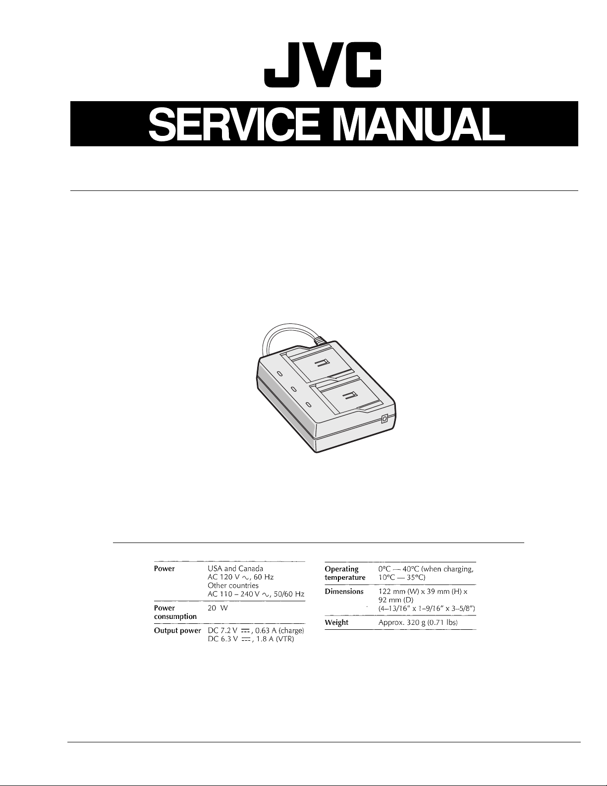
AC POWER ADAPTER/CHARGER
AA-V50U/EG/EK
SPECIFICATIONS
COPYRIGHT © 1999 VICTOR COMPANY OF JAPAN, LTD.
(The specifications shown pertain specifically to the model AA-V50U)
No. 86493
April 1999
Page 2
Important Safety Precautions
Connector
Metal sleeve
Prior to shipment from the factory, JVC products are strictly inspected to conform with the recognized product safety and electrical codes
of the countries in which they are to be sold. However, in order to maintain such compliance, it is equally important to implement the
following precautions when a set is being serviced.
䢇
Precautions during Servicing
1. Locations requiring special caution are denoted by labels and
inscriptions on the cabinet, chassis and certain parts of the
product. When performing service, be sure to read and comply with these and other cautionary notices appearing in the
operation and service manuals.
2. Parts identified by the symbol and shaded ( ) parts are
critical for safety.
Replace only with specified part numbers.
Note: Parts in this category also include those specified to com-
ply with X-ray emission standards for products using
cathode ray tubes and those specified for compliance
with various regulations regarding spurious radiation
emission.
3. Fuse replacement caution notice.
Caution for continued protection against fire hazard.
Replace only with same type and rated fuse(s) as specified.
4. Use specified internal wiring. Note especially:
1) Wires covered with PVC tubing
2) Double insulated wires
3) High voltage leads
5. Use specified insulating materials for hazardous live parts.
Note especially:
1) Insulation Tape 3) Spacers 5) Barrier
2) PVC tubing 4) Insulation sheets for transistors
6. When replacing AC primary side components (transformers,
power cords, noise blocking capacitors, etc.) wrap ends of
wires securely about the terminals before soldering.
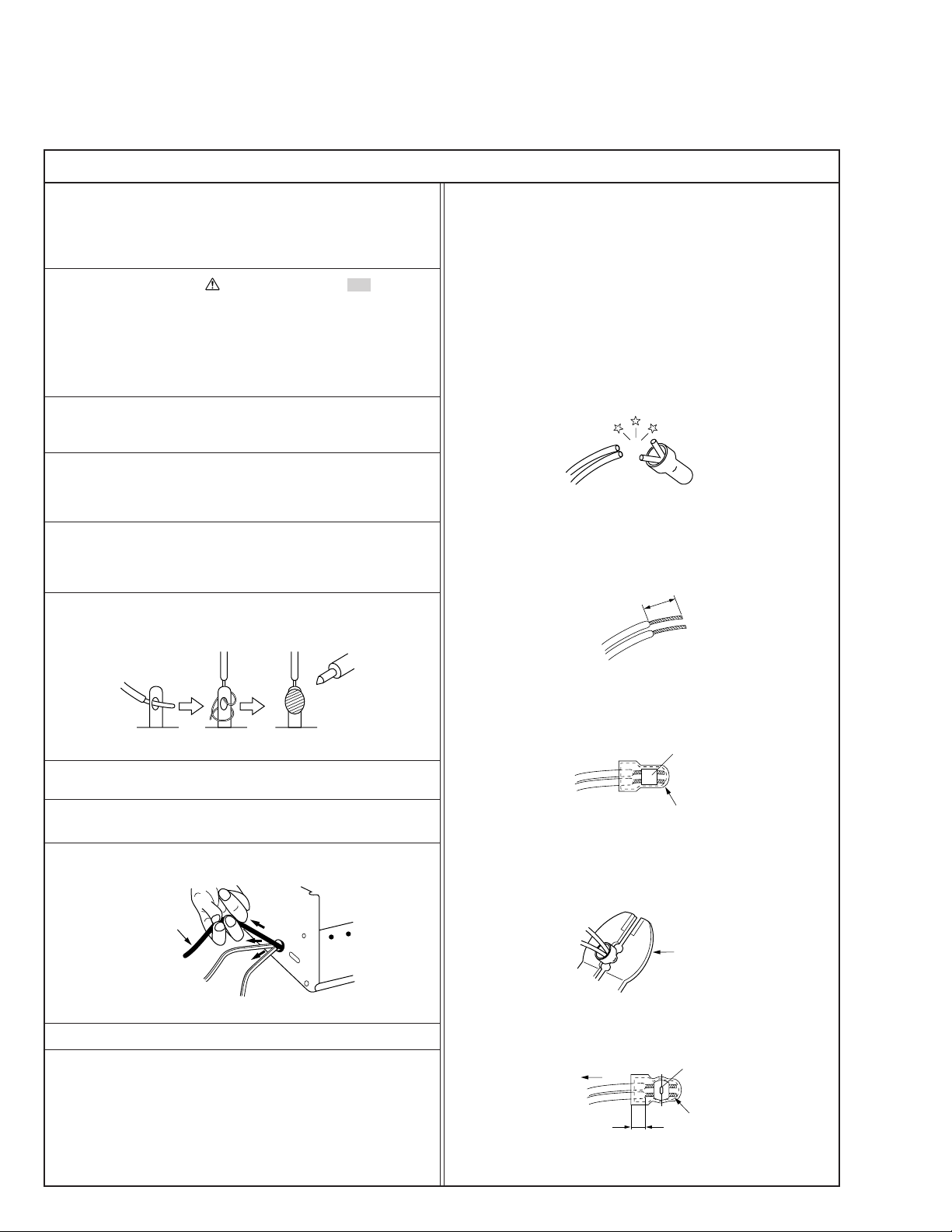
12. Crimp type wire connector
In such cases as when replacing the power transformer in sets
where the connections between the power cord and power
transformer primary lead wires are performed using crimp type
connectors, if replacing the connectors is unavoidable, in order to prevent safety hazards, perform carefully and precisely
according to the following steps.
1) Connector part number : E03830-001
2) Required tool : Connector crimping tool of the proper type
which will not damage insulated parts.
3) Replacement procedure
(1) Remove the old connector by cutting the wires at a point
close to the connector.
Important : Do not reuse a connector (discard it).
cut close to connector
Fig.3
(2) Strip about 15 mm of the insulation from the ends of
the wires. If the wires are stranded, twist the strands to
avoid frayed conductors.
15 mm
Fig.1
7. Observe that wires do not contact heat producing parts
(heatsinks, oxide metal film resistors, fusible resistors, etc.)
8. Check that replaced wires do not contact sharp edged or
pointed parts.
9. When a power cord has been replaced, check that 10-15 kg of
force in any direction will not loosen it.
Power cord
Fig.2
10. Also check areas surrounding repaired locations.
11. Products using cathode ray tubes (CRTs)
In regard to such products, the cathode ray tubes themselves,
the high voltage circuits, and related circuits are specified for
compliance with recognized codes pertaining to X-ray emission.
Consequently, when servicing these products, replace the cathode ray tubes and other parts with only the specified parts.
Under no circumstances attempt to modify these circuits.
Unauthorized modification can increase the high voltage value
and cause X-ray emission from the cathode ray tube.
Fig.4
(3) Align the lengths of the wires to be connected. Insert
the wires fully into the connector.
Fig.5
(4) As shown in Fig.6, use the crimping tool to crimp the
metal sleeve at the center position. Be sure to crimp fully
to the complete closure of the tool.
1.25
2.0
5.5
Fig.6
(5) Check the four points noted in Fig.7.
Not easily pulled free
Wire insulation recessed
more than 4 mm
Fig.7
Crimping tool
Crimped at approx. center
of metal sleeve
Conductors extended
1
S40888-01
Page 3
䢇
d'
d
Chassis
Power cord,
primary wire
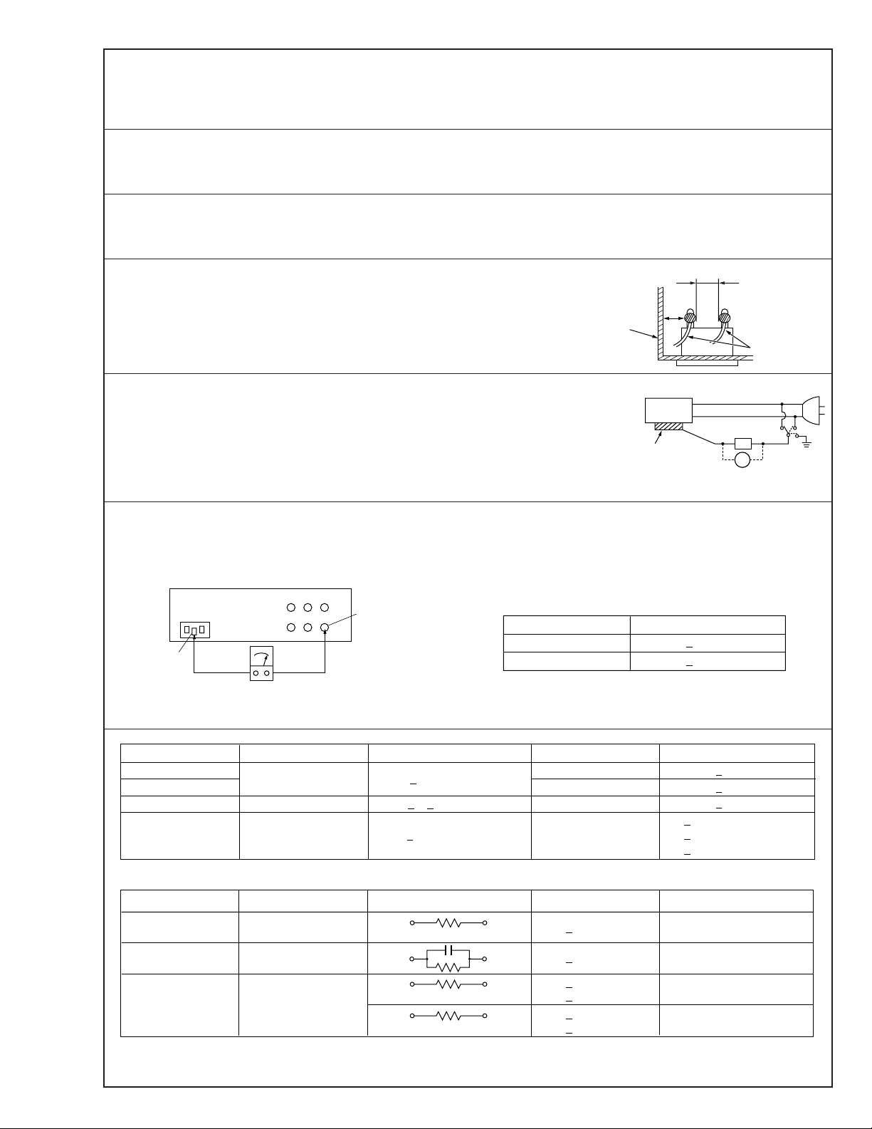
Safety Check after Servicing
Examine the area surrounding the repaired location for damage or deterioration. Observe that screws, parts and wires have been
returned to original positions, Afterwards, perform the following tests and confirm the specified values in order to verify compliance with safety standards.
1. Insulation resistance test
Confirm the specified insulation resistance or greater between power cord plug prongs and
externally exposed parts of the set (RF terminals, antenna terminals, video and audio input
and output terminals, microphone jacks, earphone jacks, etc.). See table 1 below.
2. Dielectric strength test
Confirm specified dielectric strength or greater between power cord plug prongs and exposed
accessible parts of the set (RF terminals, antenna terminals, video and audio input and output
terminals, microphone jacks, earphone jacks, etc.). See table 1 below.
3. Clearance distance
When replacing primary circuit components, confirm specified clearance distance (d), (d’) between soldered terminals, and between terminals and surrounding metallic parts. See table 1
below.
Fig. 8
4. Leakage current test
Confirm specified or lower leakage current between earth ground/power cord plug prongs
and externally exposed accessible parts (RF terminals, antenna terminals, video and audio
input and output terminals, microphone jacks, earphone jacks, etc.).
Measuring Method : (Power ON)
Insert load Z between earth ground/power cord plug prongs and externally exposed accessible parts. Use an AC voltmeter to measure across both terminals of load Z. See figure 9 and
following table 2.
Externally
exposed
accessible part
Z
V
Fig. 9
ab
c
5. Grounding (Class 1 model only)
Confirm specified or lower grounding impedance between earth pin in AC inlet and externally exposed accessible parts (Video in,
Video out, Audio in, Audio out or Fixing screw etc.).
Measuring Method:
Connect milli ohm meter between earth pin in AC inlet and exposed accessible parts. See figure 10 and grounding specifications.
AC inlet
Earth pin
AC Line Voltage
100 V
100 to 240 V
110 to 130 V
110 to 130 V
200 to 240 V
Exposed accessible part
Milli ohm meter
Fig. 10
Region
Japan
USA & Canada
Europe & Australia R 10 MΩ/500 V DC
Region Load Z
Insulation Resistance (R)
≤
R 1 MΩ/500 V DC
≥≥
1 MΩ R 12 MΩ/500 V DC
≤
Table 1 Specifications for each region
Grounding Specifications
Region
USA & Canada
Europe & Australia
Dielectric Strength
AC 1 kV 1 minute
AC 1.5 kV 1 miute
AC 1 kV 1 minute
AC 3 kV 1 minute
AC 1.5 kV 1 minute
(Class 2)
(Class 1)
Grounding Impedance (Z)
≤
Z 0.1 ohm
≤
Z 0.5 ohm
Clearance Distance (d), (d')
≤
d, d' 3 mm
≤
d, d' 4 mm
≤
d, d' 3.2 mm
≤
d 4 mm
≤
d' 8 mm (Power cord)
≤
d' 6 mm (Primary wire)
a, b, cLeakage Current (i)AC Line Voltage
100 V
110 to 130 V
110 to 130 V
220 to 240 V
Note: These tables are unofficial and for reference only. Be sure to confirm the precise values for your particular country and locality.
Japan
USA & Canada
Europe & Australia
Table 2 Leakage current specifications for each region
1 kΩ
0.15 µF
1.5 kΩ
2 kΩ
50 kΩ
2
≤
i 1 mA rms Exposed accessible parts
≤
i 0.5 mA rms
≤
i 0.7 mA peak
≤
i 2 mA dc
≤
i 0.7 mA peak
≤
i 2 mA dc
Exposed accessible parts
Antenna earth terminals
Other terminals
S40888-01
Page 4
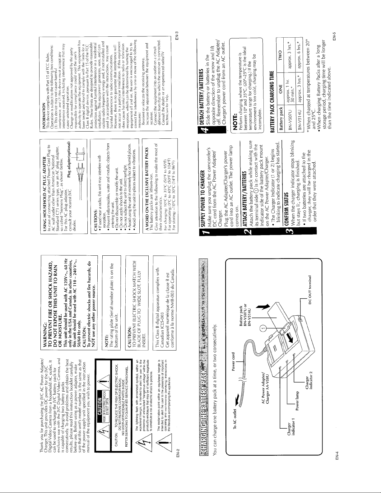
(The instruction manual is for the AA-V50U)
INSTRUCTIONS
Page 5

Page 6

PARTS LIST
SAFETY PRECAUTION
Parts identified by the symbol are critical for safety. Replace only with specified part numbers.
1. PACKING ASSEMBLY <M1>
The instruction manual to be provided with this product will differ according to the destination.
5
7
6
3
9
4
1
CABINET ASSEMBLY
<M2>
# REF No. PART No. PART NAME, DESCRIPTION
---------------- ----------------------- -----------------------------------------------------
✽✽✽✽✽✽✽✽✽✽✽✽✽✽✽✽✽✽✽✽✽✽✽✽✽✽✽✽✽
P ACKING ASSEMBLY <M1>
1 LY30833-002A PACKING CASE
2 LY30834-001A CUSHION SHEET
3 – WARRANTY CARD
4 QQR0491-002 NOISE FILTER
# REF No. PART No. PART NAME, DESCRIPTION
---------------- ----------------------- -----------------------------------------------------
5 LYT0388-001A INST. BOOK, For U
6 YU20333 SAFETY CAUTION, For U
7 QPA01702505P POLY BAG
8 LY31176-001B DC CORD, For U
9 QQR0917-002 NOISE FILTER, For EG/EK
8
2
LYT0389-001A INST. BOOK, For EG/EK
LY31176-005B DC CORD, For EG/EK
1
Page 7

2. CABINET ASSEMBL Y <M2>
For EG/EK
1
5
4
5
4
MAIN <01>
3
2
6
# REF No. PART No. PART NAME, DESCRIPTION
---------------- ----------------------- -----------------------------------------------------
✽✽✽✽✽✽✽✽✽✽✽✽✽✽✽✽✽✽✽✽✽✽✽✽✽✽✽✽✽
CABINET ASSEMBL Y <M2>
1 PTY20450-011 UPPER CASE ASSY, For U
PTY20450-012 UPPER CASE ASSY, For EG/EK
2 PTY20450-016 LOWER CASE ASSY, For U
PTY20450-017 LOWER CASE ASSY, For EG/EK
# REF No. PART No. PART NAME, DESCRIPTION
---------------- ----------------------- -----------------------------------------------------
3 PTY20450-030 POWER CORD, For U
4 PTY20450-050 LOCK LEVER
5 PTY20450-051 LOCK SPRING
6 PTY20292-165 SCREW, X3
6
RATING LABEL
PTY21032-007 POWER CORD, For EG
PTY21032-008 POWER CORD, For EK
2
Page 8

3. SCHEMATIC DIAGRAM
5
4
3
2
1
ABCD
3
Page 9

NOTE: When ordering parts, be sure to order according to
the Part Number indicated in the Parts List.
Safety precautions
The components identified by the
critical for safety. For continued safety, replace
safety critical components only with manufacturer’s
recommended parts.
symbol are
EFG
H
4
Page 10

4. MAIN CIRCUIT BOARD
F1
250V 2A For U
250V 1A For EG/EK
2A 250V
CAUTION:
FOR CONTINUED PROTECTION AGAINST
FIRE HAZARD, REPLACE ONLY WITH SAME
TYPE AND RATED FUSE.
ATTENTION:
POUR UNE PROTECTION PERMANENTE
CONTRE LES RISQUE D’INCENDE,
REMPLACER LE FUSIBLE PAR UN AUTRE
DE MEME TYPE ET DE MEME TENSION.
5
Page 11

# REF No. PART No. PART NAME, DESCRIPTION # REF No. PART No. PART NAME, DESCRIPTION
---------------- ----------------------- ----------------------------------------------------- ----------------- ----------------------- -----------------------------------------------------
✽✽✽✽✽✽✽✽✽✽✽✽✽✽✽✽✽✽✽✽✽✽✽✽✽✽✽✽✽✽✽✽✽✽✽
MAIN BOARD ASSEMBLY <01>
PW1 PTY20450-002 MAIN BOARD ASSY, For U
PW1 PTY20450-003 MAIN BOARD ASSY, For EG/EK
IC1 M61030AFP IC 24pin SOP
IC5 MIP1640002DN IC
Q10 2SB1240TV2 TRANSISTOR
Q11 2SA812MT1B TRANSISTOR
Q21 UN2211TX DIG.TRA.
Q81 2SB1240TV2 TRANSISTOR
Q82 2SA812MT1B CHIP TRANSISTOR
Q82 2SA1037AKT146 CHIP TRANSISTOR
D10 F10P10Q S.B DIODE 100V 10A
D21 AU02A DIODE 600V 0.8A
D22 AU02A DIODE 600V 0.8A
D23 DI106 B. DIODE 600V 1A
D27 1SS133 DIODE 80V 130mA
ZD2 BZX55C12 DIODE
ZD3 BZX55C12 DIODE
ZD82 BZX55C12 DIODE
ZD84 BZX55C12 DIODE
LED1 YQ10531-540 LED RED POWER
LED2 YQ10531-542 LED GREEN CHARGE/FINISH
LED3 YQ10531-542 LED GREEN CHARGE/FINISH
R1 QRZ0125-681 RESISTOR 680Ω 1/4W
R2 QRZ0125-681 RESISTOR 680Ω 1/4W
R3 PTY20290-202 RESISTER 1kΩ 1/10W
R4 QRZ0125-101 RESISTOR 100Ω 1/4W
R5 QRZ0125-103 RESISTOR 10kΩ 1/4W
R6 QRZ0125-101 RESISTOR 100Ω 1/4W
R7 QRZ0125-103 RESISTOR 10kΩ 1/4W
R8 PTY20292-262 RESISTOR, For U 3.9MΩ
R9 PTY20290-212 RESISTER 47.0kΩ 1/10W 1%
R10 PTY20290-212 RESISTER 47.0kΩ 1/10W 1%
R11 PTY20292-227 RESISTER 10.0kΩ 1/10W 1%
R12 PTY20292-227 RESISTER 10.0kΩ 1/10W 1%
R13 PTY20292-225 RESISTER 4.7kΩ 1/10W
R14 PTY20292-225 RESISTER 4.7kΩ 1/10W
R15 QRZ0125-221 RESISTOR 220Ω 1/4W
R16 QRZ0125-221 RESISTOR 220Ω 1/4W
R17 PTY20290-211 RESISTER 33kΩ 1/10W
R18 PTY20292-279 RESISTER 30.0kΩ 1/10W 1%
R19 PTY20450-203 RESISTER 10.5kΩ 1/10W 1%
R20 PTY20290-209 RESISTER 22kΩ 1/10W
R21 PTY20292-253 RESISTER 620Ω 1/10W
R22 PTY20290-210 RESISTER 30kΩ 1/10W
R23 PTY20290-203 RESISTER 1.2kΩ 1/10W
R24 PTY20450-200 RESISTOR 20.0kΩ 1/4W 1%
R25 PTY20290-207 RESISTER 11.5kΩ 1/10W 1%
R26 PTY20292-269 FUSE RESISTER 4.7Ω
R27 PTY10067-606 RESISTER 100Ω 1/10W
R28 PTY10067-604 RESISTER 10kΩ 1/10W
R29 PTY20290-207 RESISTER 11.5kΩ 1/10W 1%
R50 PTY20450-201 RESISTOR 11Ω 1/4W
R52 PTY20292-266 RESISTOR 0.33Ω 1W 2%
R70 QRN141J-105 RESISTOR 1MΩ 1/4W
R71 PTY20292-202 RESISTOR 68kΩ 1W
R72 QRZ0125-3R3 RESISTOR 3.3Ω 1/4W
R73 PTY20450-202 RESISTOR 33Ω 1/4W
R77 QRZ0125-101 RESISTOR 100Ω 1/4W
J10 PTY20450-204 RESISTER 0Ω 1/8W
C21 YQ10626-408 CAPACITOR 1000pF 500V
C22 PTY20450-300 CAPACITOR 470µF 16V
C23 QETL1CM-227 CAPACITOR 220µF 16V
C24 PTY10067-511 CAPACITOR 0.1µF 25V
C26 PTY10067-511 CAPACITOR 0.1µF 25V
C27 PTY10067-511 CAPACITOR 0.1µF 25V
C28 PTY10067-511 CAPACITOR 0.1µF 25V
C29 PTY10067-511 CAPACITOR 0.1µF 25V
C30 PTY20290-302 CAPACITOR 0.047µF 25V
C31 PTY20290-304 CAPACITOR 0.1µF 25V
C32 PTY20290-302 CAPACITOR 0.047µF 25V
C33 PTY10067-511 CAPACITOR 0.1µF 25V
C34 PTY20450-301 CAPACITOR 0.0022µF 50V
C35 QEHA1HM-475 CAPACITOR 4.7µF 50V
C36 QEHA1HM-475 CAPACITOR 4.7µF 50V
C40 PTY20292-303 CAPACITOR 0.068µF 275V
C41 YQ10626-402 CAPACITOR 47µF 400V
C42 YQ10626-403 C. CAPACITOR 3300pF 500V
C43 PTY10067-511 CHIP C.CAPACITOR 0.1µF 25V
C44 PTY20292-310 E CAPACITOR 47µF 16V
C46 QEHA1HM-475 E CAPACITOR 4.7µF 50V
C47 PTY20292-368 CAPACITOR 1000pF
C48 PTY20292-368 CAPACITOR 1000pF
C49 PTY10067-511 CAPACITOR 0.1µF 25V
L1 PTY20292-503 COIL
L2 PTY20450-400 COIL
L11 PTY20450-401 FILTER
L12 PTY20292-501 INDUCTOR
PHC1 PS25011M PHOTO COUPLER, For U
PHC1 PS25611M PHOTO COUPLER, For EG/EK
T1 PTY20450-450 TRANS
JK1 YQ21032-301 DC JACK
VR1 PTY20450-451 VOLUME
HS1 PTY20450-070 HEAT SINK A
HS2 PTY20450-071 HEAT SINK B
OT1 PTY20450-060 SCREW
OT2 PTY20450-061 SCREW
F1 PTY20450-40 FUSE, For U 250V 2A
F1 PTY20450-41 FUSE, For EG/EK 250V 1A
6
9904 (Ozaki)-M12ACC E. & O. E. No. 86493
Page 12

VICTOR COMPANY OF JAPAN, LIMITED
VIDEO DIVISION
S40894
Printed in Japan
 Loading...