

Page 1
SERVICE MANUAL
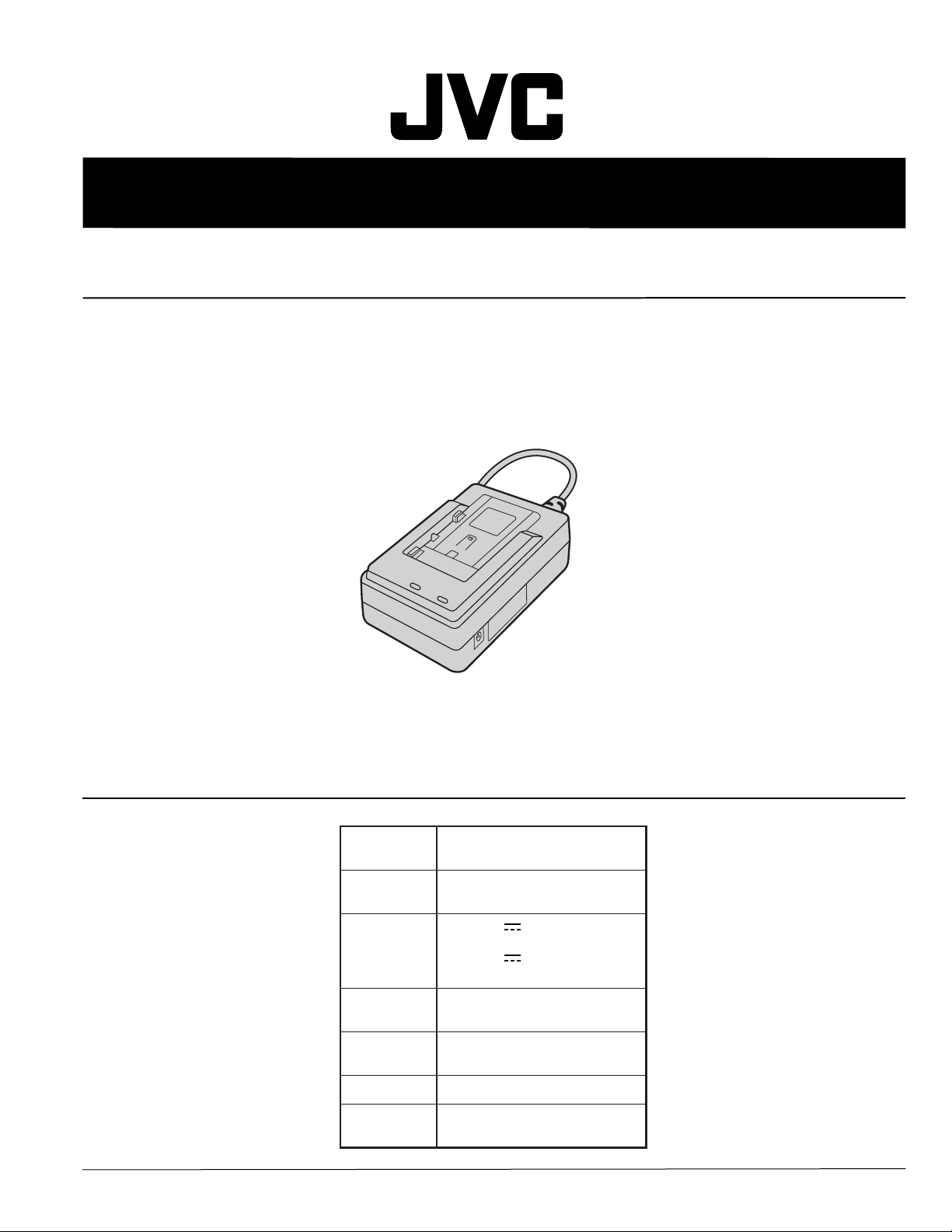
AC POWER ADAPTER/CHARGER
AA-V40EG/EK
SPECIFICATIONS
Power
Power
consumption
Output
Operating
temperature
Charging
temperature
Dimensions
Weight
This service manual is made from all recycled paper.
COPYRIGHT © 2000 VICTOR COMPANY OF JAPAN, LTD
AC 110 V — 240 V,
50 Hz/60 Hz
23 W
DC 7.2 V , 1.2 A
(When charging)
DC 6.3 V
(When supplying power)
0°C — 40°C
10°C — 35°C
68 (W) x 38 (H) x 110 (D) mm
AA-V40EG : Approx. 260 g
AA-V40EK : Approx. 340 g
, 1.8 A
No.86592
November 2000
Page 2

Important Safety Precautions
Prior to shipment from the factory, JVC products are strictly inspected to conform with the recognized product safety and electrical codes
of the countries in which they are to be sold. However, in order to maintain such compliance, it is equally important to implement the
following precautions when a set is being serviced.
v
Precautions during Servicing
1. Locations requiring special caution are denoted by labels and
inscriptions on the cabinet, chassis and certain parts of the
product. When performing service, be sure to read and comply with these and other cautionary notices appearing in the
operation and service manuals.
2. Parts identified by the symbol and shaded ( ) parts are
critical for safety.
Replace only with specified part numbers.
Note: Parts in this category also include those specified to com-
ply with X-ray emission standards for products using
cathode ray tubes and those specified for compliance
with various regulations regarding spurious radiation
emission.
3. Fuse replacement caution notice.
Caution for continued protection against fire hazard.
Replace only with same type and rated fuse(s) as specified.
4. Use specified internal wiring. Note especially:
1) Wires covered with PVC tubing
2) Double insulated wires
3) High voltage leads
5. Use specified insulating materials for hazardous live parts.
Note especially:
1) Insulation Tape 3) Spacers 5) Barrier
2) PVC tubing 4) Insulation sheets for transistors
6. When replacing AC primary side components (transformers,
power cords, noise blocking capacitors, etc.) wrap ends of
wires securely about the terminals before soldering.
12. Crimp type wire connector
In such cases as when replacing the power transformer in sets
where the connections between the power cord and power
transformer primary lead wires are performed using crimp type
connectors, if replacing the connectors is unavoidable, in order to prevent safety hazards, perform carefully and precisely
according to the following steps.
1) Connector part number : E03830-001
2) Required tool : Connector crimping tool of the proper type
which will not damage insulated parts.
3) Replacement procedure
(1) Remove the old connector by cutting the wires at a point
close to the connector.
Important : Do not reuse a connector (discard it).
cut close to connector
Fig.3
(2) Strip about 15 mm of the insulation from the ends of
the wires. If the wires are stranded, twist the strands to
avoid frayed conductors.
15 mm
Fig.1
7. Observe that wires do not contact heat producing parts
(heatsinks, oxide metal film resistors, fusible resistors, etc.)
8. Check that replaced wires do not contact sharp edged or
pointed parts.
9. When a power cord has been replaced, check that 10-15 kg of
force in any direction will not loosen it.
Power cord
Fig.2
10. Also check areas surrounding repaired locations.
11. Products using cathode ray tubes (CRTs)
In regard to such products, the cathode ray tubes themselves,
the high voltage circuits, and related circuits are specified for
compliance with recognized codes pertaining to X-ray emission.
Consequently, when servicing these products, replace the cathode ray tubes and other parts with only the specified parts.
Under no circumstances attempt to modify these circuits.
Unauthorized modification can increase the high voltage value
and cause X-ray emission from the cathode ray tube.
Fig.4
(3) Align the lengths of the wires to be connected. Insert
the wires fully into the connector.
Metal sleeve
Connector
Fig.5
(4) As shown in Fig.6, use the crimping tool to crimp the
metal sleeve at the center position. Be sure to crimp fully
to the complete closure of the tool.
1.25
2.0
5.5
Fig.6
(5) Check the four points noted in Fig.7.
Not easily pulled free
Wire insulation recessed
more than 4 mm
Fig.7
Crimping tool
Crimped at approx. center
of metal sleeve
Conductors extended
1
S40888-01
Page 3
v
Safety Check after Servicing
Examine the area surrounding the repaired location for damage or deterioration. Observe that screws, parts and wires have been
returned to original positions, Afterwards, perform the following tests and confirm the specified values in order to verify compliance with safety standards.
1. Insulation resistance test
Confirm the specified insulation resistance or greater between power cord plug prongs and
externally exposed parts of the set (RF terminals, antenna terminals, video and audio input
and output terminals, microphone jacks, earphone jacks, etc.). See table 1 below.
2. Dielectric strength test
Confirm specified dielectric strength or greater between power cord plug prongs and exposed
accessible parts of the set (RF terminals, antenna terminals, video and audio input and output
terminals, microphone jacks, earphone jacks, etc.). See table 1 below.
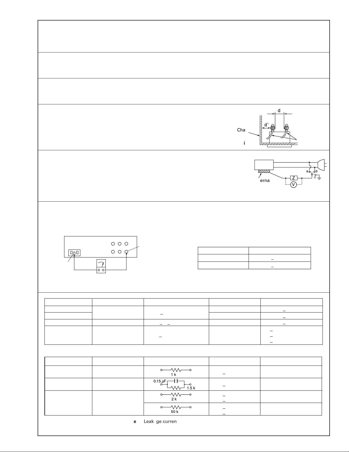
3. Clearance distance
When replacing primary circuit components, confirm specified clearance distance (d), (d’) between soldered terminals, and between terminals and surrounding metallic parts. See table 1
below.
Chassis
Fig. 8
4. Leakage current test
Confirm specified or lower leakage current between earth ground/power cord plug prongs
and externally exposed accessible parts (RF terminals, antenna terminals, video and audio
input and output terminals, microphone jacks, earphone jacks, etc.).
Measuring Method : (Power ON)
Insert load Z between earth ground/power cord plug prongs and externally exposed accessible parts. Use an AC voltmeter to measure across both terminals of load Z. See figure 9 and
following table 2.
5. Grounding (Class 1 model only)
Confirm specified or lower grounding impedance between earth pin in AC inlet and externally exposed accessible parts (Video in,
Video out, Audio in, Audio out or Fixing screw etc.).
Measuring Method:
Connect milli ohm meter between earth pin in AC inlet and exposed accessible parts. See figure 10 and grounding specifications.
AC inlet
Earth pin
Exposed accessible part
Grounding Specifications
Region
USA & Canada
Europe & Australia
Externally
exposed
accessible part
Grounding Impedance (Z)
d
d'
Fig. 9
≤
Z 0.1 ohm
≤
Z 0.5 ohm
Power cord,
primary wire
Z
V
ab
c
Milli ohm meter
Fig. 10
AC Line Voltage
100 V
100 to 240 V
110 to 130 V
110 to 130 V
200 to 240 V
Region
Japan
USA & Canada
Europe & Australia R 10 MΩ/500 V DC
Region Load Z
100 V
110 to 130 V
110 to 130 V
220 to 240 V
Note: These tables are unofficial and for reference only. Be sure to confirm the precise values for your particular country and locality.
Japan
USA & Canada
Europe & Australia
Table 2 Leakage current specifications for each region
Insulation Resistance (R)
≤
R 1 MΩ/500 V DC
≥≥
1 MΩ R 12 MΩ/500 V DC
≤
Table 1 Specifications for each region
1k
Ω
0.15 µF
1.5 k
Ω
Dielectric Strength
AC 1 kV 1 minute
AC 1.5 kV 1 miute
AC 1 kV 1 minute
AC 3 kV 1 minute
AC 1.5 kV 1 minute
i 1 mA rms Exposed accessible parts
i 0.5 mA rms
i 0.7 mA peak
2k
Ω
i 2 mA dc
i 0.7 mA peak
50 k
Ω
i 2 mA dc
2
≤
≤
≤
≤
≤
≤
(Class 2)
(Class 1)
Clearance Distance (d), (d')
≤
d, d' 3 mm
≤
d, d' 4 mm
≤
d, d' 3.2 mm
≤
d 4 mm
≤
d' 8 mm (Power cord)
≤
d' 6 mm (Primary wire)
a, b, cLeakage Current (i)AC Line Voltage
Exposed accessible parts
Antenna earth terminals
Other terminals
S40888-01
Page 4
EN-2
Thank you for purchasing the JVC AC Power Adapter/Charger. This unit provides DC power for the JVC Digital Video
Camera from a household AC outlet. It can be used to recharge the JVC battery pack for exclusive use with the JVC Digital
Video Camera, and is capable of charging two battery packs consecutively. To avoid problems and obtain the best results,
please read this instruction booklet carefully before use. Before using as a power adapter, make sure that this unit’s model
number is the same as that of the power supply unit specified in the instruction manual of the equipment you wish to power.
WARNING:
TO PREVENT FIRE OR
SHOCK HAZARD, DO
NOT EXPOSE THIS
UNIT TO RAIN OR
MOISTURE.
This unit should be used
with AC 110 V – 240 V
``
``
`,
50 Hz/60 Hz only.
CAUTION:
To prevent electric shocks
and fire hazards, do NOT
use any other power
source.
When the equipment is installed in a cabinet or
on a shelf, make sure that it has sufficient space
on all sides to allow for ventilation (10 cm or
more on both sides, on top and at the rear).
Do not block the ventilation holes.
(If the ventilation holes are blocked by a
newspaper, or cloth etc. the heat may not be
able to get out.)
No naked flame sources, such as lighted
candles, should be placed on the apparatus.
When discarding batteries, environmental
problems must be considered and the local
rules or laws governing the disposal of these
batteries must be followed strictly.
The apparatus shall not be exposed to dripping
or splashing.
Do not use this equipment in a bathroom or
places with water.
Also do not place any containers filled with
water or liquids (such as cosmetics or medicines,
flower vases, potted plants, cups etc.) on top of
this unit.
(If water or liquid is allowed to enter this
equipment, fire or electric shock may be caused.)
NOTE:
The rating plate (Serial
number plate) is on the
bottom of the unit.
CAUTION:
To prevent electric
shock, do not open the
cabinet. No user
serviceable parts inside.
Refer servicing to
qualified service
personnel.
CAUTION:
When you are not using
this unit for a long
period of time, it is
recommended that you
disconnect the power
cord from AC outlet.
WARNING—
DANGEROUS
VOLTAGE INSIDE
EN-3
IMPORTANT
Connection to the mains supply in the United Kingdom.
DO NOT cut off the mains plug from this equipment.
If the plug fitted is not suitable for the power points in
your home or the cable is too short to reach a power
point, then obtain an appropriate safety approved
extension lead or consult your dealer.
BE SURE to replace the fuse only with an identical
approved type, as originally fitted, and to replace the
fuse cover.
If nonetheless the mains plug is cut off ensure to
remove the fuse and dispose of the plug immediately,
to avoid a possible shock hazard by inadvertent
connection to the mains supply.
If this product is not supplied fitted with a mains plug
then follow the instructions given below:
DO NOT make any connection to the Larger Terminal
coded E or Green. The wires in the mains lead are
coloured in accordance with the following code:
Blue to N (Neutral) or Black
Brown to L (Live) or Red
If these colours do not correspond with the terminal
identifications of your plug, connect as follows:
Blue wire to terminal coded N (Neutral) or coloured
black.
Brown wire to terminal coded L (Live) or coloured Red.
If in doubt — consult a competent electrician.
This AC Power Adapter/Charger is for use
exclusively with JVC Digital Camcorders.
A WORD ON THE EXCLUSIVE BATTERY PACKS
The battery packs are lithium-ion.
Give attention to the following to make the most
of their characteristics.
For charging: 10°C to 35°C
For operating: 0°C to 40°C
For storing: –10°C to 30°C
CAUTIONS:
•If used near a radio, this unit may interfere
with reception.
•Prevent inflammables, water and metallic
objects from entering the unit.
•Do not disassemble or modify the unit.
•Do not apply shocks to the unit.
•Do not subject the unit to direct sunlight.
•Avoid using the unit in extremely hot or humid
places.
•Avoid using the unit in places subject to
vibrations.
EN-4
CHARGING THE BATTERY PACK
POWER indicator
CHARGE indicator
DC OUT connector
AC Power
Adapter/Charger
To AC outlet
Battery pack BN-V408U,
BN-V416U or BN-V428U
AA-V40E G/EK
INSTRUCTIONS
LYT0619-001A
BEDIENUNGSANLEITUNG
MANUEL D’INSTRUCTIONS
GEBRUIKSAANWIJZING
MANUAL DE INSTRUCCIONES
MANUALE DI INSTRUZIONI
INSTRUKTIOSNBOG
KÄYTTÖOHJEET
BRUKSANVISNING
BRUKSANVISNING
AC POWER ADAPTER/CHARGER
NETZ-/LADEGERÄT NÄTTILLSATS/BATTERILADDARE
ADAPTATEUR SECTEUR/CHARGEUR DE BATTERIE
AC-ADAPTER/BATTERILADER
NETADAPTER/ACCULADER
ADAPTADOR/CARGADOR DE CA
ALIMENTATORE CA/CARICABATTERIE
LYSNETADAPTER/OPLADER
VERKKOLAITE/AKUN LATAAJA
DEUTSCH
FRANÇAIS
NEDERLANDS
CASTELLANO
ITALIANO
DANSK
SUOMI
SVENSKA
NORSK
РУССКИЙ
ČEŠTINA
POLSKI
MAGYAR
ENGLISH
Page 5

EN-5
NOTE:
Perform charging where the temperature is
between 10°C and 35°C. 20°C to 25°C is the
ideal temperature range for charging. If the
environment is too cold, charging may be
incomplete.
* When charged at temperatures between 20°C and
25°C.
•When charging Battery Packs after a long storage
period, charging time will be longer than the time
indicated above.
1
Plug the AC Adapter/Charger’s power cord into
an AC outlet. The POWER indicator lights.
2
Remove the battery pack’s protective cap.
Attach the battery pack with the
mark
aligned with the corresponding marks on the AC
Power Adapter/Charger. The CHARGE Indicator
begins blinking to indicate charging has started.
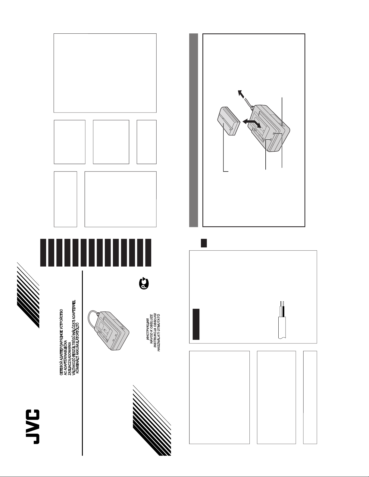
3
When the CHARGE indicator stops blinking but
stays lit, charging is finished. Slide the battery
and lift off. Remember to unplug the AC
Adapter/Charger’s power cord from the AC
outlet.
Battery pack
BN-V408U
BN-V416U (optional)
BN-V428U (optional)
Fully charging time
approx. 1 hr. 30 min.*
approx. 2 hrs.*
approx. 3 hrs. 20 min.*
EN-6
SUPPLYING POWER
You can connect the camcorder to an AC outlet
using the AC Power Adapter/Charger (if the
camcorder is supplied with a DC cord).
1
Plug the AC Adapter/Charger’s power cord into
an AC outlet.2Connect the AC Adapter to the camcorder.
NOTES:
●
Be sure to use the DC cord provided with
your camcorder.
●
When using the provided DC cord, make sure
you connect the end of the cable with the
core filter to the camcorder. The core filter
improves performance of equipment.
To AC outlet
AC Power
Adapter/Charger
Power cord
To DC Input
connector
To DC OUT
connector
DC cord
EN-7
● The AC Power Adapter/Charger is specifically
designed to charge BN-V408U, BN-V416U and/
or BN-V428U Battery Packs.
● When charging a brand new Battery Pack, or one
that’s been in storage for an extended period, the
Charging Indicator may not come on. In this case,
remove the Battery Pack, then reattach and try
charging again.
● If you connect the DC Cord to the DC Connector
while a Battery Pack is being charged, power will
be supplied to the camcorder and charging will
end incomplete.
● Vibration noise can sometimes be heard coming
from the inside of the AC Power Adapter/Charger.
This is normal.
● The AC Power Adapter/Charger processes
electricity internally, and will become warm
during use. This is normal. Make sure to use the
AC Power Adapter/Charger in well-ventilated
areas only.
● If the battery operation time remains extremely
short even after having been fully charged, the
battery is worn out and needs to be replaced.
Please purchase a new one.
DURING USE . . .
SPECIFICATIONS
Power
Power
consumption
Output
Operating
temperature
Charging
temperature
Dimensions
Weight
AC 110 V — 240 V,
50 Hz/60 Hz
23 W
DC 7.2 V , 1.2 A
(When charging)
DC 6.3 V
, 1.8 A
(When supplying power)
0°C — 40°C
10°C — 35°C
68 (W) x 38 (H) x 110 (D) mm
AA-V40EG : Approx. 260 g
AA-V40EK : Approx. 340 g
VICTOR COMPANY OF JAPAN, LIMITED
COPYRIGHT© 2000 VICTOR COMPANY OF JAPAN, LTD.
EG/EK
Printed in Japan
1200AYV
*
UN
*
SW
AA-V40EG/EK
Page 6

SAFETY PRECAUTION
Parts identified by the symbol are critical for safety. Replace only with specified part numbers.
1. PACKING ASSEMBLY <M1>
The instruction manual to be provided with this product will differ according to the destination.
3
6
5
8
2
CABINET ASSEMBLY <M2>
1
# REF No. PART No. PART NAME, DESCRIPTION # REF No. PART No. PART NAME, DESCRIPTION
--------------- ----------------------- ----------------------------------------------------- ---------------- ----------------------- ------------------------------------------------------
✽✽✽✽✽✽✽✽✽✽✽✽✽✽✽✽✽✽✽✽✽✽✽✽✽✽✽✽✽✽
P ACKING ASSEMBLY <M1>
1 LY31574-001A PACKING CASE
2 LY31383-001A CUHION SHEET
3 BT-54008-2 GUARANTY.CARD
!
5 YU30364 SAFETY SHEET, For EK
1
6 QPA01702505P POLY BAG
!
8 LYT0619-001A INST. BOOK
Page 7

2. CABINET ASSEMBLY <M2>
6
5
MAIN &
TERMINAL ASSY <01>
1
3
5
2
4
4
RATING LABEL
#!REF No. PAR T No. PAR T NAME, DESCRIPTION
----------------------- ------------------------------ ----------------------------------------------------------------------------
✽✽✽✽✽✽✽✽✽✽✽✽✽✽✽✽✽✽✽✽✽✽✽✽✽✽✽✽✽✽✽✽✽✽
CABINET ASSEMBL Y <M2>
! 1 PTY20591-013 UPPER CASE ASSY
! 2 PTY20483-023 LOWER CASE
! 3 YQ10531-006 POWER CORD For EG
! PTY20080-034 POWER CORD For EK
4 YQ10531-011 SCREW,x2
5 PTY20545-055 SCREW,x3
6 PTY20591-053 SWITCH COVER
2
Page 8

3. SCHEMATIC DIAGRAM
5
4
AC110
NOTE :
CN1
When ordering parts, be sure to order according to the Part Number
indicated in the Parts List.
MIAN & TERMINAL
2200P
2200P
1221304
3
PC123YS
2
PC123YS
1
3
ABCD
Page 9

0.22
C35
0.22
Safety precautions
The components identified by the symbol ! are
critical for safety . For continued safety, replace
safety critical components only with manufacturer’s
recommended parts.
CN2
TP15
TP16
Q27
UN2211
R60
10K
SV
SG
TERMINAL
SW1
SV
SG
DE FG
4
Page 10

4. CIRCUIT BOARD
5
Page 11

5. ELECTRICAL PARTS LIST
#!REF No. PART No. PART NAME, DESCRIPTION
----------------------- ------------------------------ ----------------------------------------------------------------------------
✽✽✽✽✽✽✽✽✽✽✽✽✽✽✽✽✽✽✽✽✽✽✽✽✽✽✽✽✽✽✽✽✽✽
MAIN & TERMINAL BOARD ASSY <01>
! PW1 PTY20591-503 MAIN & TERMINAL BOARD ASSY
! HS1 PTY20483-071 HEAT SINK A
! HS2 PTY20591-072 HEAT SINK B
OT1 PTY10067-551 SCREW
IC21 M61030AFP CHARGE COTROL IC 24pin SOP
Q1 FS2KM18A MOS FET
Q2 2SD2227 TRANSISTER
Q3 2SD2227 TRANSISTER
Q21 UN2211TX DIG.TRANSISTER
Q22 2SA1037AK/QR/-X CHIP TRANSISTER
Q23 2SB1592 TRANSISTER
Q24 2SA1037AK/QR/-X TRANSISTER
Q25 2SA1037AK/QR/-X TRANSISTER
Q26 2SA1037AK/QR/-X TRANSISTER
Q27 UN2211TX DIG TRANSISTOR
D1 S1WBA60 B.DIODE! 600V 1A
D5 1SS244T77 DIODE 200V 6A
D6 1SS244T77 DIODE 200V 6A
D21 MA7D56 DIODE 60V 10A
ZD1 MTZJ12C-T2 ZENER DIODE 12V
ZD2 MTZJ6.2B-T2 ZENER DIODE 6.2V 500mW
ZD21 MTZJ12C-T2 ZENER DIODE 12V
ZD22 MTZJ12C-T2 ZENER DIODE 12V
ZD23 MTZJ12C-T2 ZENER DIODE 12V
ZD24 MTZJ12C-T2 ZENER DIODE 12V
ZD25 MA4047NM ZENER DIODE 4.7V 500mW
LED1 YQ10531-540 LED RED POWER
LED2 YQ10531-542 LED GREEN CHARGE
R1 QRN141J-105 RESISTOR 1MΩ 1/4W
R3 PTY10067-601 MF RESISTOR 0.62Ω 1W
R4 QRE141J-334Y RESISTOR 330kΩ 1/4W
R5 QRE141J-334Y RESISTOR 330kΩ 1/4W
R7 QRE141J-751Y RESISTOR 750Ω 1/4W
R8 NRSA02J-103X MG RESISTOR 10kΩ 1/10W
R9 NRSA02J-272X MG RESISTOR 2.7kΩ 1/10W
R10 NRSA02J-104X MG RESISTOR 100kΩ 1/10W
R11 NRSA02J-682X MG RESISTOR 6.8kΩ 1/10W
R12 QRE141J-181Y RESISTOR 180Ω 1/4W
R13 QRE141J-334Y RESISTOR 330kΩ 1/4W
R14 QRE141J-334Y RESISTOR 330kΩ 1/4W
R15 NRSA02J-182X MG RESISTOR 1.8kΩ 1/10W
R16 NRSA02J-753X MG RESISTOR 75kΩ 1/10W
R22 NRSA02J-621X MG RESISTOR 620Ω 1/10W
R23 PTY20539-605 MF RESISTOR 0.20Ω 2W
R24 NRSA02J-102X MG RESISTOR 1kΩ 1/10W
R25 NRSA02J-101X MG RESISTOR 100Ω 1/10W
R26 NRSA02J-103X MG RESISTOR 10kΩ 1/10W
R27 NRSA02J-102X MG RESISTOR 1kΩ 1/10W
R28 NRSA02J-151X MG RESISTOR 150Ω 1/10W
R29 PTY20539-601 MG RESISTOR 47.0kΩ 1/10W
R30 PTY20539-601 MG RESISTOR 47.0kΩ 1/10W
R31 NRSA02F-103X MG RESISTOR 10.0kΩ 1/10W
R32 NRSA02J-103X MG RESISTOR 10kΩ 1/10W
R33 NRSA02J-333X MG RESISTOR 33kΩ 1/10W
R34 PTY20539-601 MG RESISTOR 47.0kΩ 1/10W
R35 PTY20539-602 MG RESISTOR 11.0kΩ 1/10W
R36 NRSA02F-6192X MG RESISTOR 61.9kΩ 1/10W
R37 PTY20539-603 MG RESISTOR 1.0kΩ 1/10W
R38 PTY20539-601 MG RESISTOR 47.0kΩ 1/10W
R39 PTY20539-604 MG RESISTOR 1.3kΩ 1/10W
#!REF No. PART No. PART NAME, DESCRIPTION
----------------------- ------------------------------ ----------------------------------------------------------------------------
R40 PTY20450-200 MG RESISTOR 20.0kΩ 1/4W
R41 NRSA02F-1152X MG RESISTOR 11.5kΩ 1/10W
R42 NRSA02F-1152X MG RESISTOR 11.5kΩ 1/10W
R43 QRE141J-103Y MF RESISTOR 10kΩ 1/4W
R45 NRSA02J-222X MG RESISTOR 2.2kΩ 1/10W
R46 NRSA02J-472X MG RESISTOR 4.7kΩ 1/10W
R47 NRSA02J-221X MG RESISTOR 220Ω 1/10W
R48 NRSA02J-102X MG RESISTOR 1kΩ 1/10W
R49 NRSA02J-473X MG RESISTOR 47kΩ 1/10W
R50 NRSA02F-5622X MG RESISTOR 56.2kΩ 1/10W
R51 NRSA02F-5112X MG RESISTOR 51.1kΩ 1/10W
R52 NRSA02J-103X MG RESISTOR 10kΩ 1/10W
R53 NRSA02J-103X MG RESISTOR 10kΩ 1/10W
R54 NRSA02J-103X MG RESISTOR 10kΩ 1/10W
R55 NRSA02J-103X MG RESISTOR 10kΩ 1/10W
R56 NRSA02J-103X MG RESISTOR 10kΩ 1/10W
R60 NRSA02J-103X MG RESISTOR 10kΩ 1/10W
! C1 QFZ9072-104 F CAPACITOR 0.1µF 250V
C2 YQ10626-402 E CAPACITOR 47µF 400V
C3 PTY10067-651 CAPACITOR 1500pF 250V
C4 NCB21CK-224X CAPACITOR 0.22µF 16V
C5 PTY10067-653 CAPACITOR 0.01µF 50V
C6 NCB21HK-391X CAPACITOR 390pF 50V
! C7 PTY20538-611 CAPACITOR 2200pF 250V
! C8 PTY20538-611 CAPACITOR 2200pF 250V
C9 NDC21HJ-680X CAPACITOR 68pF 50V
C10 NDC21HJ-151X CAPACITOR 150pF 50V
C11 NDC21HJ-151X CAPACITOR 150pF 50V
C21 PTY10067-657 CAPACITOR 0.01µF 250V
C22 PTY20292-321 E CAPACITOR 680µF 16V
C23 QETL1CM-227 E CAPACITOR 220µF 16V
C24 NCB21CK-224X CAPACITOR 0.22µF 16V
C25 NCF21EZ-104X CAPACITOR 0.1µF 25V
C26 NCB21CK-224X CAPACITOR 0.22µF 16V
C27 NCB21EK-473X CAPACITOR 0.047µF 25V
C28 NCB21HK-473X CAPACITOR 0.047µF 50V
C29 NCB21EK-104X CAPACITOR 0.1µF 25V
C30 NCF21EZ-104X CAPACITOR 0.1µF 25V
C31 NCB21HK-222X CAPACITOR 0.0022µF 50V
C32 QEHA1HM-475 E CAPACITOR 4.7µF 50V
C33 NCF21EZ-104X CAPACITOR 0.1µF 25V
C34 NCF21EZ-104X CAPACITOR 0.1µF 25V
C35 QFLA1HJ-224 F CAPACITOR 0.22µF 50V
! T1 PTY20538-801 SW TRANS
VR1 PTY20483-101 VOLUME 2kΩ
! F1 PTY20450-041 FUSE 1A 250V
JK1 YQ21032-301 DC JACK
! L1 PTY20450-401 LINE FILTER
L12 PTY10067-702 BEAD INDUCTOR
L21 PTY10067-703 COIL
! PHC1 PC123YS PHOTO COUPLER
SW1 PTY20545-662 SWITCH
WR1 PTY20591-052 FLAT CABLE (5P)
TB1 PTY20545-051 TERMINAL,x5
CN1 PTY20603-056 CONNECTOR
(VP)-M14ACC E&0.E NO.86592
6
Page 12

VICTOR COMPANY OF JAPAN, LIMITED
VIDEO DIVISION
S40894
Printed in Japan
 Loading...