

Page 1
SERVICE MANUAL
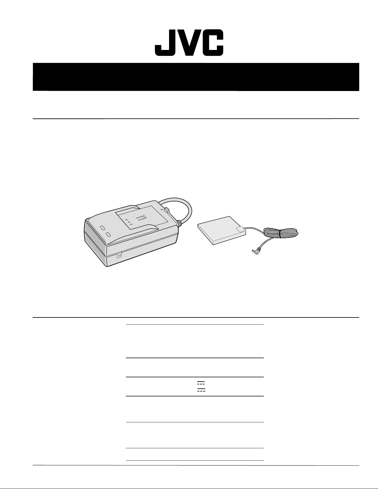
AC POWER ADAPTER/CHARGER
AA-V100U
SPECIFICATIONS
Power
Power
consumption
Output power
Operating
temperature
Dimensions
Weight
This service manual is printed on 100% recycled paper.
COPYRIGHT © 2001 VICTOR COMPANY OF JAPAN, LTD
USA and Canada
AC 120 V`, 60 Hz
Other countries
AC 110 V – 240 V`, 50 Hz/60 Hz
23 W
DC 7.2 V , 1.2 A (charge)
DC 6.3 V , 1.8 A (VTR)
0°C to 40°C (32°F to 104°F) [when
charging, 10°C to 35°C (50°F to
95°F)]
68 mm (W) x 44 mm (H) x
110 mm (D)
(2–11/16" x 1–3/4" x 4–3/8")
Approx. 255 g (0.57 lbs)
No.86648
June 2001
Page 2
Important Safety Precautions
cut close to connector
Prior to shipment from the factory, JVC products are strictly inspected to conform with the recognized product safety and electrical codes
of the countries in which they are to be sold. However, in order to maintain such compliance, it is equally important to implement the
following precautions when a set is being serviced.
v
Precautions during Servicing
1. Locations requiring special caution are denoted by labels and
inscriptions on the cabinet, chassis and certain parts of the
product. When performing service, be sure to read and comply with these and other cautionary notices appearing in the
operation and service manuals.
2. Parts identified by the
critical for safety.
Replace only with specified part numbers.
Note: Parts in this category also include those specified to com-
ply with X-ray emission standards for products using
cathode ray tubes and those specified for compliance
with various regulations regarding spurious radiation
emission.
3. Fuse replacement caution notice.
Caution for continued protection against fire hazard.
Replace only with same type and rated fuse(s) as specified.
4. Use specified internal wiring. Note especially:
1) Wires covered with PVC tubing
2) Double insulated wires
3) High voltage leads
5. Use specified insulating materials for hazardous live parts.
Note especially:
1) Insulation Tape 3) Spacers 5) Barrier
2) PVC tubing 4) Insulation sheets for transistors
6. When replacing AC primary side components (transformers,
power cords, noise blocking capacitors, etc.) wrap ends of
wires securely about the terminals before soldering.
symbol and shaded ( ) parts are
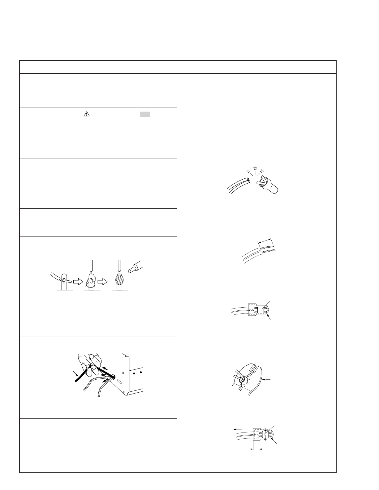
12. Crimp type wire connector
In such cases as when replacing the power transformer in sets
where the connections between the power cord and power
transformer primary lead wires are performed using crimp type
connectors, if replacing the connectors is unavoidable, in order to prevent safety hazards, perform carefully and precisely
according to the following steps.
1) Connector part number : E03830-001
2) Required tool : Connector crimping tool of the proper type
which will not damage insulated parts.
3) Replacement procedure
(1) Remove the old connector by cutting the wires at a point
close to the connector.
Important : Do not reuse a connector (discard it).
Fig.3
(2) Strip about 15 mm of the insulation from the ends of
the wires. If the wires are stranded, twist the strands to
avoid frayed conductors.
15 mm
Fig.1
7. Observe that wires do not contact heat producing parts
(heatsinks, oxide metal film resistors, fusible resistors, etc.)
8. Check that replaced wires do not contact sharp edged or
pointed parts.
9. When a power cord has been replaced, check that 10-15 kg of
force in any direction will not loosen it.
Power cord
Fig.2
10. Also check areas surrounding repaired locations.
11. Products using cathode ray tubes (CRTs)
In regard to such products, the cathode ray tubes themselves,
the high voltage circuits, and related circuits are specified for
compliance with recognized codes pertaining to X-ray emission.
Consequently, when servicing these products, replace the cathode ray tubes and other parts with only the specified parts.
Under no circumstances attempt to modify these circuits.
Unauthorized modification can increase the high voltage value
and cause X-ray emission from the cathode ray tube.
Fig.4
(3) Align the lengths of the wires to be connected. Insert
the wires fully into the connector.
Metal sleeve
Connector
Fig.5
(4) As shown in Fig.6, use the crimping tool to crimp the
metal sleeve at the center position. Be sure to crimp fully
to the complete closure of the tool.
1.25
2.0
5.5
Fig.6
(5) Check the four points noted in Fig.7.
Not easily pulled free
Wire insulation recessed
more than 4 mm
Fig.7
Crimping tool
Crimped at approx. center
of metal sleeve
Conductors extended
1
S40888-01
Page 3
v
d'
d
Chassis
Power cord,
primary wire
Safety Check after Servicing
Examine the area surrounding the repaired location for damage or deterioration. Observe that screws, parts and wires have been
returned to original positions, Afterwards, perform the following tests and confirm the specified values in order to verify compliance with safety standards.
1. Insulation resistance test
Confirm the specified insulation resistance or greater between power cord plug prongs and
externally exposed parts of the set (RF terminals, antenna terminals, video and audio input
and output terminals, microphone jacks, earphone jacks, etc.). See table 1 below.
2. Dielectric strength test
Confirm specified dielectric strength or greater between power cord plug prongs and exposed
accessible parts of the set (RF terminals, antenna terminals, video and audio input and output
terminals, microphone jacks, earphone jacks, etc.). See table 1 below.
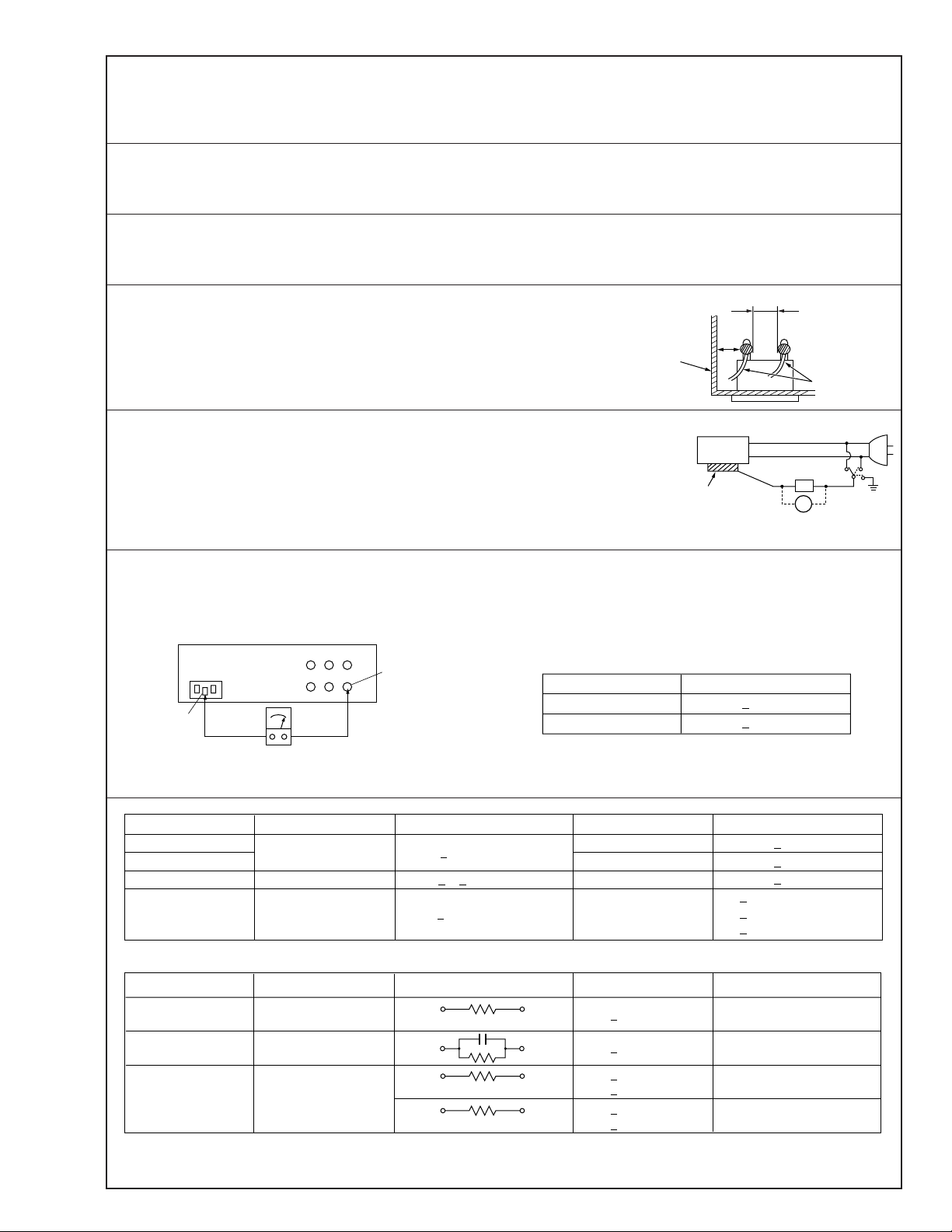
3. Clearance distance
When replacing primary circuit components, confirm specified clearance distance (d), (d’) between soldered terminals, and between terminals and surrounding metallic parts. See table 1
below.
Fig. 8
4. Leakage current test
Confirm specified or lower leakage current between earth ground/power cord plug prongs
and externally exposed accessible parts (RF terminals, antenna terminals, video and audio
input and output terminals, microphone jacks, earphone jacks, etc.).
Measuring Method : (Power ON)
Insert load Z between earth ground/power cord plug prongs and externally exposed accessible parts. Use an AC voltmeter to measure across both terminals of load Z. See figure 9 and
following table 2.
Externally
exposed
accessible part
Z
V
Fig. 9
ab
c
5. Grounding (Class 1 model only)
Confirm specified or lower grounding impedance between earth pin in AC inlet and externally exposed accessible parts (Video in,
Video out, Audio in, Audio out or Fixing screw etc.).
Measuring Method:
Connect milli ohm meter between earth pin in AC inlet and exposed accessible parts. See figure 10 and grounding specifications.
AC inlet
Earth pin
AC Line Voltage
100 V
100 to 240 V
110 to 130 V
110 to 130 V
200 to 240 V
Exposed accessible part
Milli ohm meter
Fig. 10
Region
Japan
USA & Canada
Europe & Australia R 10 MΩ/500 V DC
Region Load Z
Insulation Resistance (R)
≤
R 1 MΩ/500 V DC
≥≥
1 MΩ R 12 MΩ/500 V DC
≤
Table 1 Specifications for each region
Grounding Specifications
Region
USA & Canada
Europe & Australia
Dielectric Strength
AC 1 kV 1 minute
AC 1.5 kV 1 miute
AC 1 kV 1 minute
AC 3 kV 1 minute
AC 1.5 kV 1 minute
(Class 2)
(Class 1)
Grounding Impedance (Z)
≤
Z 0.1 ohm
≤
Z 0.5 ohm
Clearance Distance (d), (d')
≤
d, d' 3 mm
≤
d, d' 4 mm
≤
d, d' 3.2 mm
≤
d 4 mm
≤
d' 8 mm (Power cord)
≤
d' 6 mm (Primary wire)
a, b, cLeakage Current (i)AC Line Voltage
100 V
110 to 130 V
110 to 130 V
220 to 240 V
Note: These tables are unofficial and for reference only. Be sure to confirm the precise values for your particular country and locality.
Japan
USA & Canada
Europe & Australia
Table 2 Leakage current specifications for each region
1 kΩ
0.15 µF
1.5 kΩ
2 kΩ
50 kΩ
2
≤
i 1 mA rms Exposed accessible parts
≤
i 0.5 mA rms
≤
i 0.7 mA peak
≤
i 2 mA dc
≤
i 0.7 mA peak
≤
i 2 mA dc
Exposed accessible parts
Antenna earth terminals
Other terminals
S40888-01
Page 4

SAFETY PRECAUTION
Parts identified by the symbol are critical for safety. Replace only with specified part numbers.
1. PACKING AND ACCESSORY ASSEMBLY <M1>
The instruction manual to be provided with this product will differ according to the destination.
7
8
CARTON LABEL
6
2
FINAL
ASSEMBLY <M2>
# REF No. PART No. PART NAME, DESCRIPTION # REF No. PART No. PART NAME, DESCRIPTION
--------------- ----------------------- ----------------------------------------------------- ---------------- ----------------------- ------------------------------------------------------
1
******************************
PACKING ASSEMBLY <M1>
1 LY31381-001A PACKING CASE
2 LY32337-001A CUHION SHEET
6 QPA01702505P POLY BAG
1
7 BT-51005-5 WARRANTY INF.
!
8 LYT0841-001A INST. BOOK(EN,FR,SP)
Page 5

2 FINAL ASSEMBLY <M2>
1
6
8
MAIN &
TERMINAL BOARD
<91>
5
2
4
7
5
3
4
RATING LABEL
#!REF No. PAR T No. PAR T NAME, DESCRIPTION
----------------------- ------------------------------ ----------------------------------------------------------------------------
******************************
FINAL ASSEMBLY <M2>
! 1 LY32286-001A UPPER CASE
! 2 PTY20483-021 LOWER CASE
! 3 PTY20290-040 AC POWER CORD
4 YQ10531-011 TAP SCREW, X2 LOWER
5 PTY20545-055 TAP SCREW, X2
6 PTY20754-052 SWITCH COVER
7 PTY20754-054 LOCK LEVER
8 PTY20754-055 LENS
2
Page 6

K
%
3. SCHEMATIC DIAGRAM
NOTE :
When ordering parts, be sure to order according to the Part Number
indicated in the Parts List.
5
1
9
TP1
L
N
AC110 240V
4
50/60Hz
MAIN&TERMINAL
F1
C1
L1
/250
R10
OPEN
0.068
Q1
FS2KM18A
D
ZD1
16V
TF1
0Ω
S
HEAT_SINK_A
1SS244
G
D2
1A
TP2
C8
1000p
D1
D21
MA7D56
T1
3.4
7
HEAT_SINK_B
C2
47
/400
C21
0.01u
5
R3
R4
C3
4700p
C5
68p
PHC1
R9
150K
Q2
D4
1SS244
R2
240K
R1
240K240K100K
R5
560
C4
1000p
R6
470
34.6K
ZD2
9.1V
R8
115K
1%
D3
1SS244
R7
1%
Q3
1.2
8
9
680u
C22
/16
ZD21
16V
TP4
L21
LED1
RED
R22
680
3
1000p
C7
R81
150 1/4W
C51
ZD26
4.7V
R27
1K
2
ZD25
4444444
8.2V
Q23
PHC1
C35
4444444
0.1u
R28
47
C36
0.1u
R56
0.047u
10K
TP14
Q22
R54
OPEN
R51
22K
R53
33K
C34
0.01u
C28
0.022u
TP9
C29
R46
R55
C27
0.0022u
4.7K
4.7K
0.047u
C45
0.1u
R29
220K
1%
TP10
R52
470
R30
220K
R32
10K
1%
1%
TP11
0.1u
C30
C37
0.1u
VCC
FBAD
GND
ADPT
PHC
FBCC
SW
VCHK
TH
DCJK
IC21
M61031FP
I IN
VREF
ADJ3
ADJ2
ADJ1
LED1
LED2
VDD
LED2
GREEN
TP18
C31
2200p
R3
115
1
R47
220
1/4W
CC
RC
TP17
R33
100K
1
3
ABC D
Page 7

Safety precautions
The components identified by the symbol ! are
critical for safety . For continued safety, replace
safety critical components only with manufacturer’s
recommended parts.
LED2
GREEN
TP4
L21
LED1
RED
R22
680
R23
0.1
C38
1000p
TP3
1%
R24
24.9K
1%
C23
470u
/16
R26
34.8K
1%
TF2
0Ω
JP21
C24
0.22u
JP22
ZD27
6.2V
TP15
JK1
TP16
R25
100
1/4W
Q21
TP8
16V
ZD23
C25
0.22u
TP6
C43
0.1u
CN2
T
S
_
TP7
TERMINAL PWB
+
T
S
++
T
SW1
__
TP13
R41
1%
28.7K
C31
2200p
115K
R34
R36
56.2K
1%
1%
R37
1.00K
1%
R72 R74
Q25
R70
56.2K
R35
10.0K
1%
10K 10K
R76
10K
R73
R75
10K
10K
1%
44.2K
Q27
Q26
R71
1%
TP19
TP17
R33
100K
R47
220
1/4W
TP18
DE FG
R38
47K
R60
10K
1.15K
VR1
2K
C44
C32
R42
11.5K
1%
R39
1%
4.7u
0.1u
/50
4
Page 8

4. CIRCUIT BOARD
1A 250V
CAUTION:
FOR CONTINUED PROTECTION AGAINST
FIRE HAZARD, REPLACE ONLY WITH SAME
TYPE AND RATED FUSE.
ATTENTION:
POUR UNE PROTECTION PERMANENTE
CONTRE LES RISQUE D'INCENDE,
REMPLACER LES FUSIBLE PAR UN AUTRE
DE MEME TYPE ET DE MEME TENSION.
5
Page 9

5. ELECTRICAL PARTS LIST
#!REF No. PAR T No. PAR T NAME, DESCRIPTION
----------------------- ------------------------------ ----------------------------------------------------------------------------
******************************
MAIN & TERMINAL BOARD ASSEMBLY <91>
! PW1 PTY20754-502 MAIN & TERMINAL BOARD ASSY
IC21 M61031FP Charge control IC 20pin SOP
Q1 FS2KM18A MOS FET
Q2 2SD2226KT146 TRANSISTER
Q3 2SD2226KT146 TRANSISTER
Q22 DTC114YUA-X DIG.TRANSISTOR
Q23 DTA114YUA-X DIG.TRANSISTOR
Q25 2SA1576A/QR/-X TRANSISTOR
Q26 2SA1577A/QR/-X TRANSISTOR
Q27 UN2211TX DIG.TRANSISTOR
D1 S1WBA60 B. DIODE 600V 1A
D2 1SS244T77 DIODE 200V 0.2A
D3 1SS244T77 DIODE 200V 0.2A
D4 1SS244T77 DIODE 200V 0.2A
D21 MA7D56 DIODE 60V 10A
ZD1 MTZJ16T-77 ZENER DIODE 16V 500mW
ZD2 MTZJ9.1B ZENER DIODE 9.1V 500mW
ZD21 MTZJ16T-77 ZENER DIODE 16V 500mW
ZD23 MTZJ16T-77 ZENER DIODE 16V 500mW
ZD25 MA4082N/M/-T2 ZENER DIODE 8.2V 500mW
ZD26 MA4047NM ZENER DIODE 4.7V 500mW
ZD27 MTZJ6.2B-T2 ZENER DIODE 6.2V 500mW
LED1 YQ10531-540 LED RED POWER
LED2 YQ10531-542 LED GREEN CHARGE
R1 QRE141J-244Y RESISTOR 240KØ 1/4W
R2 QRE141J-244Y RESISTOR 240KØ1/4W
R3 QRE141J-244Y RESISTOR 240KØ 1/4W
R4 QRE141J-104Y RESISTOR 100kØ 1/4W
R5 QRE141J-561Y RESISTOR 560Ø 1/4W
R6 QRE141J-471Y RESISTOR 470Ø 1/4W
R7 NRSA63F-3482X MG RESISTOR 34.8kØ 1/16W 1%
R8 NRSA63F-1153X MG RESISTOR 115kØ 1/16W 1%
R9 NRSA63J-154X MG RESISTOR 150kØ 1/16W
R22 QRE141J-681Y RESISTOR 680Ø 1/4W
R23 QRZ0192-R10X MF RESISTOR 0.1Ø 1W 2%
R24 NRSA63F-2492X MG RESISTOR 24.9kØ 1/16W 1%
R25 QRE141J-101Y RESISTOR 100Ø 1/4W
R26 NRSA63F-3482X MG RESISTOR 34.8kØ 1/16W 1%
R27 NRSA63J-102X MG RESIST OR 1kØ 1/16W
R28 NRSA63J-470X MG RESIST OR 47Ø 1/16W
R29 PTY20754-511 MG RESISTOR 220kØ 1/16W 1%
R30 PTY20754-511 MG RESISTOR 220kØ 1/16W 1%
R32 PTY20754-512 MG RESISTOR 10kØ 1/16W 1%
R33 NRSA63J-104X MG RESIST OR 100kØ 1/16W
R34 NRSA63F-5622X MG RESISTOR 56.2kØ 1/16W 1%
R35 PTY20754-512 MG RESISTOR 10kØ 1/16W 1%
R36 NRSA63F-1153X MG RESISTOR 115kØ 1/16W 1%
R37 PTY20754-513 MG RESISTOR 1.00kØ 1/16W 1%
R38 PTY20754-514 MG RESISTOR 47kØ 1/16W 1%
R39 NRSA63F-1151X MG RESISTOR 1.15kØ 1/16W 1%
R41 NRSA63F-2872X MG RESISTOR 28.7kØ 1/16W 1%
R42 NRSA63F-1152X MG RESISTOR 11.5kØ 1/16W 1%
R46 NRSA63J-472X MG RESIST OR 4.7kØ 1/16W
#!REF No. PAR T No. PAR T NAME, DESCRIPTION
----------------------- ------------------------------ ----------------------------------------------------------------------------
R47 QRE141J-221Y RESISTOR 220Ø 1/4W
R51 NRSA63J-223X MG RESISTOR 22kØ 1/16W
R52 NRSA63J-471X MG RESISTOR 470Ø 1/16W
R53 NRSA63J-333X MG RESISTOR 33kØ1/16W
R55 NRSA63J-473X MG RESISTOR 47kØ 1/16W
R56 NRSA63J-103X MG RESISTOR 10kØ 1/16W
R60 NRSA63J-103X MG RESISTOR 10kØ 1/16W
R70 NRSA63F-5622X MG RESISTOR 56.2kØ 1/16W 1%
R71 NRSA63F-4422X MG RESISTOR 44.2kØ 1/16W 1%
R72 NRSA63J-103X MG RESISTOR 10kØ 1/16W
R73 NRSA63J-103X MG RESISTOR 10kØ 1/16W
R74 NRSA63J-103X MG RESISTOR 10kØ 1/16W
R75 NRSA63J-103X MG RESISTOR 10kØ 1/16W
R76 NRSA63J-103X MG RESISTOR 10kØ 1/16W
R81 QRE141J-150Y RESISTOR 150Ø 1/4W
! C1 PTY20292-303 F CAPACITOR 0.068µF275V
C2 YQ10626-402 E CAPACITOR 47µF400V
C3 NCB31HK-472X CAPACITOR 4700pF 50V
C4 PTY20754-521 F CAPACITOR 1000pF 50V
C5 NDC31HJ-680X CAPACITOR 68pF 50V
! C7 PTY20292-368 CAPACITOR 1000pF 250V
! C8 PTY20292-368 CAPACITOR 1000pF 250V
C21 PTY10067-657 CAPACITOR 0.01µF250V
C22 PTY20292-321 E CAPACITOR 680µF16V
C23 QETL1CM-477 E CAPACITOR 470µF16V
C24 PTY20754-522 CAPACITOR 0.22µF16V
C25 QFLA1HJ-224 F CAPACITOR 0.22µF50V
C27 NCB31HK-222X CAPACITOR 0.0022µF50V
C28 NCB31EK-223X CAPACITOR 0.022µF25V
C29 PTY20754-523 CAPACITOR 0.047µF25V
C30 PTY20754-524 CAPACITOR 0.1µF50V
C31 NCB31HK-222X CAPACITOR 0.0022µF50V
C32 QEHA1HM-475 E CAPACITOR 4.7µF50V
C34 PTY20754-525 CAPACITOR 0.01µF50V
C35 PTY20754-526 CAPACITOR 0.1µF16V
C36 PTY20754-526 CAPACITOR 0.1µF16V
C37 PTY20754-524 CAPACITOR 0.1µF50V
C38 NCB31HK-102X CAPACITOR 0.001µF50V
C43 PTY20754-524 CAPACITOR 0.1µF50V
C44 PTY20754-524 CAPACITOR 0.1µF50V
C45 PTY20754-526 CAPACITOR 0.1µF16V
C51 NCB31CK-473X CAPACITOR 0.047µF16V
! L1 PTY20450-401 LINE FILTER
L21 PTY10067-703 COIL
! PHC1 PC817X1 PHOTO COUPLER
! orPC817A PHOTO COUPLER
! T1 PTY20754-531 SW TRANS
VR1 PTY20483-101 VOLUME 2kØ
JK1 YQ21032-301 DC JACK
! F1 PTY20450-041 FUSE 1A 250V
! HS1 PTY20483-071 HEAT SINK A
! HS2 PTY20591-072 HEAT SINK B
OT1 PTY10067-551 TAP SCREW,X2(HEAT SINK)
SW1 PTY20545-662 SWITCH
WR1 PTY20591-052 FLAT CABLE(4P)
TB1 PTY20754-053 BATTERY TERMINAL,X3
(VP)-M1ACC
6
Page 10

JVC SERVICE & ENGINEERING COMPANY OF AMERICA
DIVISION OF JVC AMERICAS CORP.
Head office
East Coast
Midwest
West Coast
Atlanta
Hawaii
Head office
Montreal
Vancouver
1700 Valley Road Wayne, New Jersey 07470-9976
:
10 New Maple Avenue Pine Brook, New Jersey 07058-9641
:
705 Enterprise Street Aurora, Illinois 60504-8149
:
5665 Corporate Avenue Cypress, California 90630-0024
:
1500 Lakes Parkway Lawrenceville, Georgia 30043-5857
:
2969 Mapunapuna Place Honolulu, Hawaii 96819-2040
:
JVC CANADA INC.
:
21 Finchdene Square Scarborough, Ontario M1X 1A7
:
16800 Rte Trans-Canadienne, Kirkland, Quebec H9H 5G7
:
13040 Worster Court Richmond, B.C. V6V 2B3
(973)315-5000
(973)396-1000
(630)851-7855
(714)229-8011
(770)339-2582
(808)833-5828
(416)293-1311
(514)871-1311
(604)270-1311
S40895-03
Printed in Japan
 Loading...