

Page 1

SERVICE
MANUAL
Model 330
Model 340 SC
Model 370 SC
Hughes-JVC Technology Corporation
2310 Camino Vida Roble, Carlsbad, CA 92009-1504
☎
760-929-5300
DECLARATION OF CONFORMITY
760-929-5410
AX
F
service@hjt.com
e
✉
-
PER ISO/IEC GUIDE 22 AND EN 45014
Page 2

Manufacturer: Hughes-JVC Technology Corporation
2310 Camino Vida Roble
Carlsbad, CA 92009-1504
USA
Hughes-JVC declares that this product conforms to the following
Product Specifications (Directive/Standard):
Safety: EN 60950
IEC 950 (1992)
EMC: EN 55022 (1988) / CISPR-22 (1986) Class "A"
EN 50082-1 (1992) / IEC 801-2 (1991)
EN 50082-1 (1992) / IEC 801-3 (1984)
EN 50082-1 (1992) / IEC 801-4 (1988)
ANSI C63.4-1992, FCC, Part 15, Class A
In addition, the above product complies with the requirements of the
Low Voltage Directive 73/23 EEC and the EMC Directive 89/336/EEC.
105662 First Edition January 1998
Rev A September 1998
Hughes-JVC Technology Corporation
is ISO 9001 Registered and Certified.
Confidential and proprietary information.
© Copyright 1998 by Hughes-JVC Technology Corporation.
All worldwide rights reserved.
This manual was produced by Hughes-JVC Technology Corporation
and may be revised without prior notice.
No part of this manual may be reproduced in any form without
the express written permission of Hughes-JVC Technology Corporation.
®
is a registered trademark of Hughes-JVC Technology Corporation.
ILA
iii
Model 330, 340SC and 370SC Service Manual
Page 3
Safety Information
Introduction
Before operating or working on a Model 330, 340SC and 370SC Projector, especially
with the cover off, please read this safety information section thoroughly. Procedures
requiring the opening of the projector covers and/or contact with electrical components
should be performed by qualified service personnel. Strictly adhere to all notes and
warnings.
Safety Equipment
Safety equipment specified in the Hughes-JVC Series 300 Projector Service and
Operator’s Training Course and certification program or equivalent should be used for
maintenance of the equipment.
Safety
Warnings and Cautions
Warnings and Cautions
Warnings and Cautions in this manual should be read thoroughly and strictly adhered to.
Warning and Caution symbols and definitions are as follows:
WARNING!!!
and/or specific procedure or situation that could result in personal injury if
improperly performed.
CAUTION!
hazards that could cause severe eye injury or a specific procedure or situation
that could result in damage to the equipment if improperly used.
The following important safety instructions are designed to insure your safety and the
long life of your projector. Be sure to read these safety instructions thoroughly and adhere
to all warnings given below.
Warns user of a potential safety hazard or potential light
Warns user of a potential electric shock hazard
This device complies with Part 15 of the FCC Rules. Operation is subject to the following
two conditions: (1) this device may not cause harmful interference and (2) this device
Model 330, 340SC, and 370SC Service Manual v
Page 4
Safety
must accept any interference received including interference that may cause undesired
operation.
Operation of this equipment in a residential area is likely to cause harmful interference, in
which case the user will be required to correct the interference at their own expense.
Shielded interconnect cables must be used with this equipment to insure compliance with
the pertinent RF emission limits governing this device.
Installation Safeguards
WARNING!!!
power on the projector until the damaged cable is replaced.
not
CAUTION!
If there is any visible damage to any of the cables
Place the projector on a smooth, stable and level surface
do
in an area free from dust and moisture. Do not place the equipment in direct
sunlight or near heat-radiating appliances. Smoke, steam and exposure to direct
sunlight could adversely affect the internal components. Avoid rough handling
when moving your equipment, as a strong shock could damage its internal
components.
CAUTION!
If installing a ceiling mount, use only parts supplied or
recommended by the manufacturer. Observe all instructions and warnings as
listed in this manual.
Projector Weight
The HJT projector and shipping container have a combined weight of either 512 (Model
330 and 340SC) or 550 (Model 370SC) pounds. The HJT shipping container weighs 170
pounds and the projector itself weighs either 342 (Model 330 and 340SC) or 380 (Model
370SC) pounds.
Do Not Tilt the Projector More Than 85 Degrees
Do not mount the projector on an excessively tilted base. The projector can be tilted a
maximum of 85 degrees. Mount it only on a stable, vibration-resistant base capable of
supporting at least three times its weight. If in doubt, contact the factory.
vi
Model 330, 340SC, and 370SC Service Manual
Page 5
Safety
Avoid Projector Angles of 15° to 23°
Due to voids in the prism fluid there is a dead zone of 19° ± 4°. For this reason, avoid
projector angles of 15° to 23°.
Maximum Projector to Screen Angle is 15°
The maximum vertical tilt angle from projector to screen is 15°. This is the maximum
amount of keystone correction that is possible.
Heat Safeguards
Fans
The projector has multiple fans (exact number varies with projector model number) to
cool the projector system. Do not block the intake or outflow of any of the fans.
Intense heat is emitted within the system and must be properly dissipated in order to keep
the system running properly.
CAUTION!
ports can lead to projector overheating. Do not enclose the unit in a restricted
space. Refer to the appropriate
thermal clearance and for specific clearances needed for heat dissipation. Allow
at least ten (10) minutes for projector cool down before removing power.
has stopped running. This fan protects the arc lamp from overheating.
CAUTION!
Light Safeguards
Ultra Violet and Infrared Li ght
Eye/face protection is required from ultra violet light and infrared light in accordance
with the following conditions:
1. X3 (up to 375 nanometers) shade goggles must be worn by anyone near the
projector when the lamp is lit and the cover is off.
2. X5 (375 to 700 nanometers) shade goggles when actually working on the
projector near the arc lamp source.
Do Not Block Ventilation. Blocking air intake or exhaust
Operator’s Manual
Do not unplug the power cord until after the arc lamp fan
for physical access and
vii
Model 330, 340SC, and 370SC Service Manual
Page 6
Safety
WARNING!!!
High temperature, ultraviolet and infrared light. Refer
all service to factory authorized personnel.
Ultraviolet radiation, dangerous glare, and high internal gas pressure
is present at the Xenon Arc Lamp. It is contained in a protective reflector housing
module.
DO NOT operate the Xenon Arc Lamp outside its intended standard housing or outside
of the projector.
When replacement is required, the arc lamp must be replaced as an entire module as
outlined in the Hughes-JVC Model 330, 340SC and 370SC Projector Service Manual.
No attempt should ever be made to replace the arc lamp inside its module!
The arc lamp produces dangerous intense light with hazardous levels of ultraviolet and
infrared radiation. It operates at high temperatures (180ºC, maximum 300º C or over 500º
F).
Do not touch the xenon arc lamp or any connections when the lamp is ignited or is arcing.
WARNING!!! BRIGHT LIGHT!
Never look directly at the Arc
Lamp, the lighted Projection Lens, or into the lamp housing, from any distance,
when the projector is ON and light is projected. Direct exposure to light of this
brightness can cause severe eye injury.
viii
WARNING!!!
High voltage access and safety interlock. Defeat
restricted to factory authorized service personnel!
WARNING!!!
Allow at least one minute to bleed off high voltage even after the unit has been turned off.
High voltage points up to 40,000 volts are exposed inside the covers.
Due to high voltage danger, DO NOT TOUCH:
!
White cables to CRTs—these cables can cause severe shock from a tiny, invisible
crack or hole and should never be touched while projector power is on.
!
CRT anodes—underneath the CRTs.
!
Main power +/- supply posts—if shorted with metal objects,
!
80 amps can flow across the terminals.
Model 330, 340SC, and 370SC Service Manual
Page 7
Safety
!
CRT yoke assemblies and other proximity electrical assemblies, components and
wiring—if performing the yoke rotation or width adjustment (outlined in Section
3.2), always use an
!
ANSI/ASTM 10,000 volt rated safety glove.
!
Periodically check the condition of safety gloves for cracks.
!
Arc Lamp main power ± posts.
Power Supply
The projectors operate from power sources indicated in the table below. Verify that local
power source matches these requirements before operation!
Projector Power Supplies
Power
AC
Current
Hz
Watts
330
200-240V
20
50-60
2,700
340SC
200-240V
20
50-60
3,325
370SC
200-240V
30
50-60
4,550
Handle the power cord carefully and avoid excessive bending.
A damaged cord may cause electric shock or fire. For continued safe and reliable
operation, only use cables supplied by the manufacturer for power and signal connections.
Installation should be performed by an electrician with current knowledge of electrical
codes in the country of use.
Fluid Safeguards
Certain components of the projector contain fluid. If any fluid from the projector contacts
the skin, wash off with soap and water. If any fluid from the projector splashes into the
eyes, rinse with cool running water.
Ventilation and Foreign Object Retrieval
Ensure the projector’s multiple fans are free from obstructions and operating properly.
Air filters are located at vent ports on the cover. Air filters require periodic cleaning to
ensure adequate cooling of the projector (see Section 4.3). Verify that vent ports are clear
of all obstructions.
Keep the projector free from foreign objects, such as hairpins, nails, paper, etc. Do not
attempt to retrieve such objects yourself or insert metal objects such as wire and
screwdrivers inside the unit. If an object falls inside the projector, unplug the projector
immediately and call a Hughes-JVC certified technician for removal.
ix
Model 330, 340SC, and 370SC Service Manual
Page 8

Safety
WARNING!!!
Various procedures in this manual involve the removal
and replacement of system subassemblies. Ensure that the projector AC power
plug is removed from the AC outlet
to attempting any of these procedures.
prior
x
Model 330, 340SC, and 370SC Service Manual
Page 9

Safety
xi
Model 330, 340SC, and 370SC Service Manual
Page 10

1.0 Introduction
This Model 330, 340SC and 370SC Service Manual combines three (3) similar
projector models into one (1) reference book, and should be used in conjunction
with the appropriate projector Operator’s Manual. This manual provides more
detailed information on troubleshooting and maintaining the projectors and a more
in-depth functional description of the system subassemblies than the specific
Operator’s Manual, which cover the specific projector system description,
installation, adjustments, operation, maintenance, specifications, troubleshooting
guide, and parts list.
The areas covered in this Service Manual include any similarities and differences
of functional descriptions of Model 330, 340SC and 370SC projector electronics,
service adjustments, maintenance (removal and replacement of subassemblies),
and troubleshooting.
Chapter 1---Introduction
1.1 Acronyms Used In Manual
ALPS Arc Lamp Power Supply
CH Channel
CPU Central Processing Unit
CRT Cathode Ray Tube
DSP Digital Signal Processor
EPROM Erasable Programmable Read-Only Memory
F to V Frequency to Voltage
G2 CRT Grid 2
HDB Horizontal Deflection Board
HDTV High Definition Television
HSYNC Horizontal Sync
HVPS High Voltage Power Supply
ILA® Image Light Amplifier
I/O Input/Output
I/R Infrared
kHz Kilohertz
LED Light Emitting Diode
LVPS Low Voltage Power Supply
NTSC National Television Standards Committee
PCB Printed Circuit Board
PLL Phase Lock Loop
PLUGE Picture Line-Up Generating Equipment
RAM Random Access Memory
RGB Red, Green and Blue
ROM Read Only Memory
Model 330, 340SC and 370SC Service Manual 1-1
Page 11
Chapter 1---Introduction
RTG Raster Timing Generator
SCB System Control Board
SPS System Power Supply
TTL Transistor-Transistor Logic
VAB Video Amplifier Board
VCO Voltage Controlled Oscillator
VDB Vertical Deflection Board
VIN Video Input
VPB Video Processor PCB
VSYNC Vertical Sync
VTR Video Tape Recorder
1.2 Safety
High voltages and high intensity light sources exist in the Model 330, 340SC and
370SC Projector Systems and power supplies. Prior to performing any procedures,
adjustments or maintenance review the chapter on Safety Information at the front
of this manual.
1.3 Updates
This manual will be updated with information provided by Service Bulletins and
manual supplements whenever necessary.
1.4 Hardware Compatibility
The table below lists part numbers currently compatible between the Model 330,
340SC and 370SC projectors, and those parts that are different in each.
Table 1-1
Printed Circuit Boards
DIFFERENT
Lamp Assembly
Ignitor
System Power Supply
High Voltage Power Supply
SAME
Hardware Compatibility
330
900611S
102083
104070
100562
340SC
PART NUMBERS
104651
102207
104071
100562
370SC
104120
104475
104038
103769
1-2
Raster Timing Generator
Horizontal Deflection Board
Vertical Deflection Board
Video Processing Board
100568
102523
102521
104672
Model 330, 340SC and 370SC Service Manual
100568
102523
102521
104672
100568
102523
102521
104672
Page 12
Chapter 1---Introduction
Printed Circuit Boards
Video Amplifier Board
System Controller Board
Table 1-2
Different
3,000 lumens
2,500 ANSI lumens
220V AC, 20A, 60Hz
2,700 Watts power
1,500 W Xenon arc lamp 2,000 W Xenon arc lamp 3,000 W Xenon arc lamp
Same
5.2.1 software
graphics enhancement
Projector Model Comparisons
330 Model
4,200 lumens
3,700 ANSI lumens
220V AC, 20A, 60Hz
3,325 Watts power
5.2.1 software
graphics enhancement
340SC Model
330
103774
104668
340SC
103774
104668
6,800 lumens
6,000 ANSI lumens
220V AC, 30A, 60Hz
4,550 Watts power
5.2.1 software
graphics enhancement
370SC
103774
104668
370SC Model
30 memories
decoder board option
30 memories
decoder board option
30 memories
decoder board option
Model 330, 340SC and 370SC Service Manual 1-3
Page 13

Chapter 2—Functional Descriptions
2.0 Functional Descriptions
Contents
2.1 Cover and Base............................................................................................2–2
2.2 External Power Requirements.....................................................................2–3
2.3 Electronics Systems Overview....................................................................2–3
2.4 System Power..............................................................................................2–5
System Power Supply................................................................................2–5
Arc Lamp Ignitor.......................................................................................2–9
High Voltage Power Supply......................................................................2-11
2.5 Card Cage....................................................................................................2-14
2.6 Circuit Boards .............................................................................................2-15
Raster Timing Generator Board (RTG) p/n 100568 ................................2-18
Horizontal Deflection Board P/N 102523 (HDB).....................................2-25
Vertical Deflection Board P/N 102521(VDB)..........................................2-32
Video Processor Board P/N 104672 (VPB)..............................................2-43
Video Amplifier Board P/N 103567 or 103774 (VAB)............................2-54
System Controller Board P/N 104668 (SCB)............................................2-59
Backplane Board p/n 100571...................................................................2-71
2.7 Optical Section............................................................................................2-72
CRT Assembly..........................................................................................2-72
Arc Lamp Assembly..................................................................................2-75
Optical Subassemblies...............................................................................2-76
2.8 Image Light Amplifier.................................................................................2-76
This chapter provides functional descriptions of the major assemblies in the
Model 330, 340SC and 370SC projectors.
Emphasis is placed on a description of system components to the functional block
level. A number of block diagrams are provided for user reference.
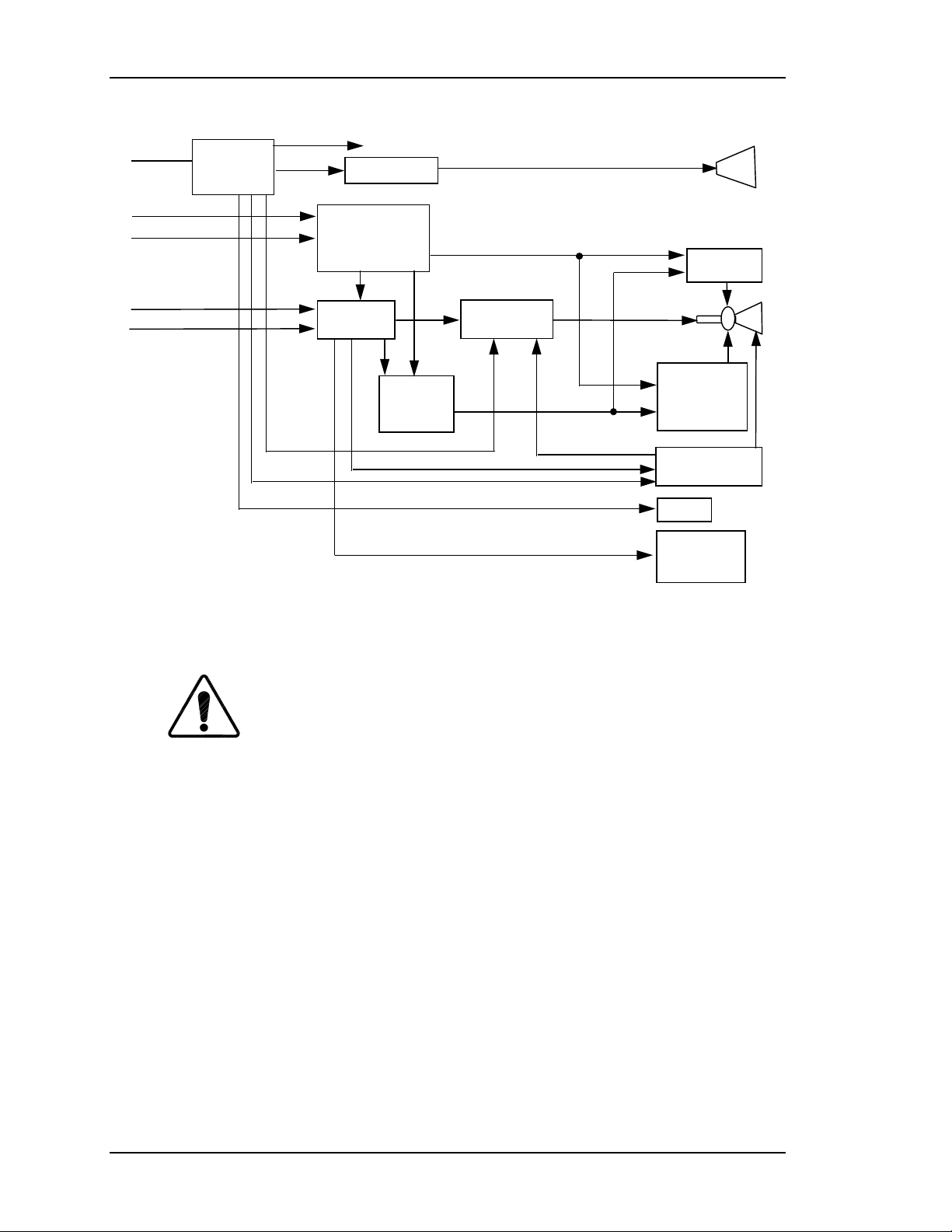
Figure 2-1 provides a block diagram overview of the HJT Model 330, 340SC and
370SC projectors. For simplicity, each major electronics assembly is shown with
signal paths between appropriate functional units. Major physical and electronics
assemblies will be described in more detail in the following sections of this
chapter.
Model 330, 340SC and 370SC Service Manual 2–1
Page 14
Chapter 2—Functional Descriptions
Low Voltage
Power Supply
Lamp Ignitor
System
Controller
Line Voltag e
RS 232
Infrared Remote
System
Power
Supply
Arc Lamp
Horizontal
Deflection
Channel 1
Channel 2
(R,G,B, H/V Sync)
Video
Processor
Figure 2-1
Model 330, 340SC and 370SC System Block Diagrams
2.1 Cover and Base
and 370SC projectors must be installed for proper operation.
Operation of the projector, other than for maintenance, with the
covers removed is not recommended and will void the projector
warranty.
CAUTION!
Video Output
Amplifier
Raster
Timing
Generator
The covers for the HJT Model 330, 340SC
Vertical
Deflection
and
Convergence
High Voltage
Power Supply
Fans
Image Light
Amplifiers
(3 each
CRTs
(3 each)
In addition to aesthetics, the covers on the Model 330, 340SC and 370SC
projectors serve several functions. The covers are an integral part of the cooling
system of the projector. Air intake filters are contained in the covers as are cooling
fans. The covers provide the operator and audience with protection from the
extremely bright light produced in the projector. The covers also serve to reduce
the noise generated by operation of the projector. The UL approval is only valid
with the covers installed since they provide the primary protection to prevent
personnel from coming into contact with the high voltages and currents contained
within the projector.
2–2 Model 330, 340SC, and 370SC Service Manual
Page 15
The HJT Model 330, 340SC and 370SC
WARNING!!!
projectors use high voltages and high currents. Operation with
covers removed exposes personnel to these dangerous conditions
and may result in serious injury or death. No user-serviceable parts
are contained within the projector. Refer all maintenance to only
factory authorized and trained technicians.
The projector cover is a two-piece molded assembly. It is fastened to the projector
frame by six (6) screws: two (2) on the rear cover; and four (4) on the front cover.
The fan intake side of the cover (right side) has filters on the intake vents.
Periodic cleaning of the filters is required and should be performed in accordance
with the procedure in this manual (Section 4.3). To avoid overheating the
projector, ensure that the cover vent ports are free of obstructions at all times and
that an adequate supply of fresh air is provided to the projector during operation.
2.2 External Power Requirements
Chapter 2—Functional Descriptions
The projectors require 208V to 240V, 50 Hz to 60 Hz, single-phase AC power.
The units are equipped with an attached AC power cord and 3-prong twist lock
plug (Model 330 and 340SC use Hubble Model 2323; Model 370SC uses Hubble
Model 2623 or equivalent).
CAUTION!
Operation at voltages and frequencies outside of these
listed parameters may cause damage to the projector and will void the warranty.
2.3 Electronics Systems Overview
The objective of this portion is to provide a good general understanding of the
projector electronics. The understanding gained will enable service personnel to
more effectively maintain the projector to produce the desired result—a great
picture on the screen —and quality you can see.
The Electronics Systems portion of this manual is based on block diagrams. The
diagrams used have been drawn with two purposes in mind. First, they are general
enough to be able to gain an understanding of the overall function of the various
components of the system. Second, the block diagrams contain enough detail to
make them valuable as a troubleshooting tool should the need arise. Schematics
are not used but, where necessary, simplified circuitry is shown to aid in
understanding the capabilities and/or limitations of the system. Discussion of
troubleshooting is included but is largely confined to symptoms and identification
of failed assemblies.
The Hughes-JVC Model 330, 340SC and 370SC projectors are multi-sync
projectors capable of data, graphics, and display from 15KHz to 90KHz
Model 330, 340SC and 370SC Service Manual 2–3
Page 16

Chapter 2—Functional Descriptions
horizontal and 45Hz to 120Hz vertical. The projected image is continuously
variable from 6 ft to 60 ft over throw distances (varies by projector model) from
10 ft to over 360 ft. All HJT Series 300 projectors are capable of keystone,
pincushion, and linearity correction. The projectors feature digital control of
functions, including convergence, picture adjustments, switching and diagnostics.
In addition, the projector provides the ability to control the relative brightness
anywhere on the screen.
The capabilities of the Model 330, 340SC and 370SC projectors are provided by a
sophisticated electronics system, which consists of power supplies, input/output
devices, and various circuit boards, and using both analog and digital components
to provide functionality with a simple user interface. The electronics systems are
assembled in modular fashion for ease of removal or maintenance.
The Model 330, 340SC and 370SC Electronics System consists of:
System Controller Board;
Video Processor Board;
Video Amplifier Boards (3);
Raster Timing Generator Board;
Horizontal Deflection Board;
Vertical Deflection Board;
Lamp Ignitor;
System Power Supply;
High Voltage Power Supply.
There are also image and sync signal inputs, an LED display, two (2) RS-232
communication ports, and two (2) IR receivers for projector control.
The digital and analog circuits of the System Controller Board direct the operation
of image and raster generation circuits as well as controlling the input/output and
power supply operation of the HJT Model 330, 340SC and 370SC projector
electronics systems.
The System Controller sets operating parameters of the system such as brightness
and contrast, produces internal test patterns and generates on-screen overlays, and
sets the timing for the raster generation to adjust phase, geometric corrections,
uniformity corrections and convergence. The System Controller houses the
program memory as well as the memory for all convergence and uniformity maps,
and has the responsibility of controlling communication with the user, power to
the other areas of the projector, and other necessary functions.
The Video Processor and Video Amplifiers select the desired input signal and
process it to produce the CRT beam modulation necessary to produce an image on
the raster.
2–4 Model 330, 340SC, and 370SC Service Manual
Page 17

Chapter 2—Functional Descriptions
The Raster Timing Generator provides timing signals to the System Controller
Board, selects the appropriate incoming sync signal and produces the timing
signals for controlling the geometry of the raster.
The Vertical and Horizontal Deflection Boards produce their respective sweep
currents to drive the deflection yokes. The Vertical Deflection Board also houses
the convergence amplifiers that drive correction coils.
The System Power Supply provides all DC power below 200V to the projector.
This includes the supply to the arc lamp/ignitor and the supply to the High
Voltage Power Supply.
The High Voltage Power Supply provides all voltages of 200V and higher. This
includes all CRT bias voltages except the cathode.
Image and sync inputs arrive in the projector at the Video Processor Board.
Inclusion of the Decoder Board is optional. User communication is accomplished
by on-screen displays, LED display output, IR remote input, or RS232
Input/Output. All of these devices are separate from, but communicate directly
with the System Controller Board.
The detailed functional description of the subassemblies are covered below in the
following order:
1. System Power.
2. Card Cage and Circuit Boards.
3. CRT Assembly.
4. Arc Lamp.
2.4 System Power
System Power Supply
The System Power Supply provides the connection between the external power
source and the projector. The System Power Supply provides all internal DC
power to the projector with the exception of that provided by the High Voltage
Power Supply (Section 2.4.3). This includes the low voltage power to the
electronics, the supply power to the HVPS, and the Arc Lamp power.
The System Power Supply is a AC-DC power supply with an input rectifier and
protection circuit and several separate switchers; one (1) for Arc Lamp power, one
(1) for +5V Standby power, one (1) for +24V Standby power, and others for the
other low voltages.
All of the power supply outputs are protected against overvoltage and overcurrent.
Overcurrent protection is a foldback circuit that limits the output current by
reducing the output voltage when an overcurrent condition is detected. An
overvoltage condition at the output of the supply will cause the affected voltage to
be shut down until input power is removed and reapplied.
Model 330, 340SC and 370SC Service Manual 2–5
Page 18
Chapter 2—Functional Descriptions
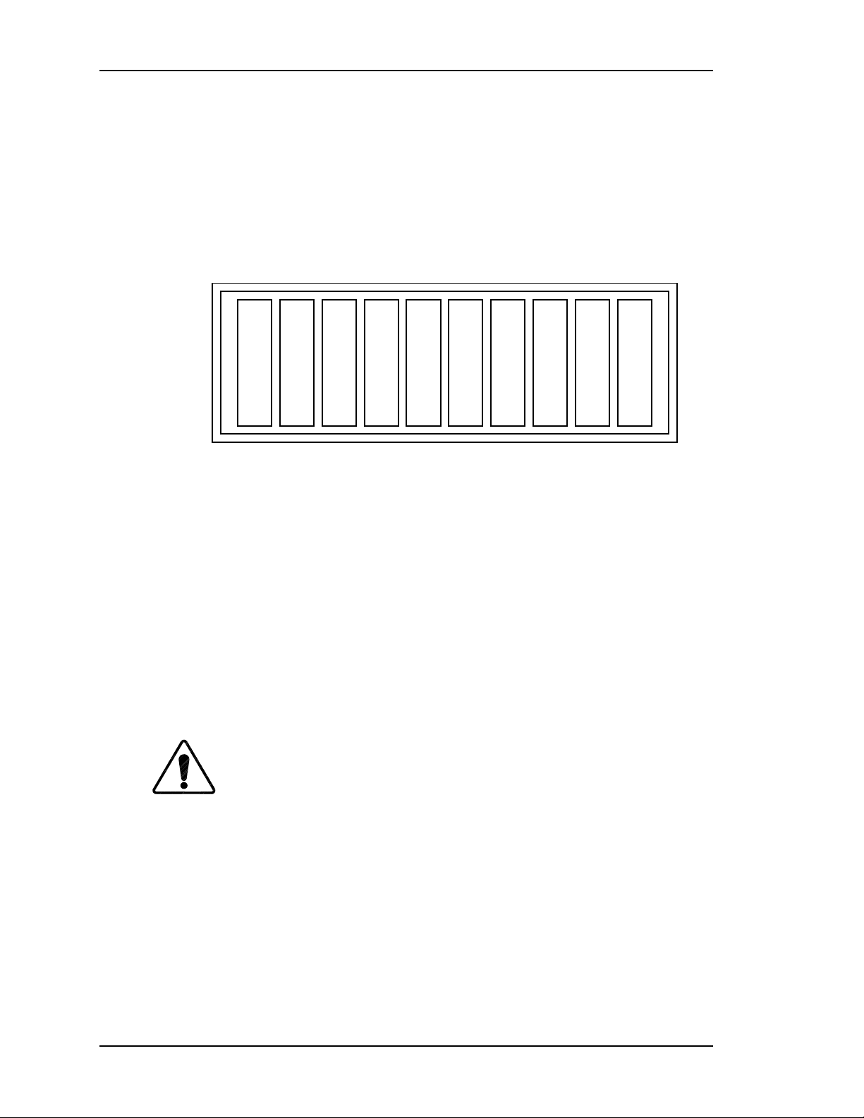
All of the SPS output voltages except Arc Lamp power are indicated by a LED
display (see ). The LEDs are located on a bar-type display on the backplane at the
left side of the card cage. The individual LEDs will be lit when the corresponding
voltage is energized. The LEDs are wired to the SPS output power using only a
current limiting resistor so when the LED is lit, it is an indication that there is a
voltage present, not necessarily the correct voltage. To verify whether or not the
voltage at the output is correct, a voltmeter must be used to probe the output
connectors J500, J501, or J502.
+5V +5V
STB
Figure 2-2
A safety interlock switch is located on top of the power supply. The interlock
+24V
STB
+6.3V +15V -15V +24V +48V+107V -200V
Backplane Status Indicators.
switch shuts off the System Power Supply whenever the cover is removed. During
normal operation with the cover installed, the switch is in the 'armed' position.
When the rear cover is removed, the switch will be released and cause power to
the projector to be interrupted. To run the unit without the cover installed,
override the interlock switch by pulling it up into the 'service' position. When the
cover is replaced, the switch will automatically be reset into the 'armed' position.
A circuit breaker is located on the right side of the System Power Supply. The
circuit breaker serves to remove all power from the projector (except for the
power at the input terminals) by switching it to the OFF position.
CAUTION!
The circuit breaker must be switched off, and the
projector must be disconnected from AC power prior to performance of any
maintenance, to ensure that all power is removed from the internal components of
the projector.
Normal operation of the System Power Supply is as follows:
When external power is applied, +5V Standby will always be energized as will the
internal SPS fans. +24V Standby power for operating the fans will be energized
whenever the lamp or electronics are turned-on and five (5) minutes after the
projector is shut down.
All other voltages are controlled by the power-up or power-down commands
issued by the operator.
2–6 Model 330, 340SC, and 370SC Service Manual
Page 19
Chapter 2—Functional Descriptions
The Arc Lamp power supply is a current-controlled supply with an open circuit
voltage of about 170V. When the Arc Lamp is operating at steady state, the power
supply provides the current set by the technician. The output of the supply has a
large capacitor that will, on initial ignition of the Arc Lamp, provide the very high
initial current necessary to ionize the xenon gas in the lamp and sustain the arc.
The current setpoint is initially set at the factory and must be reset by the
technician whenever an Arc Lamp is replaced.
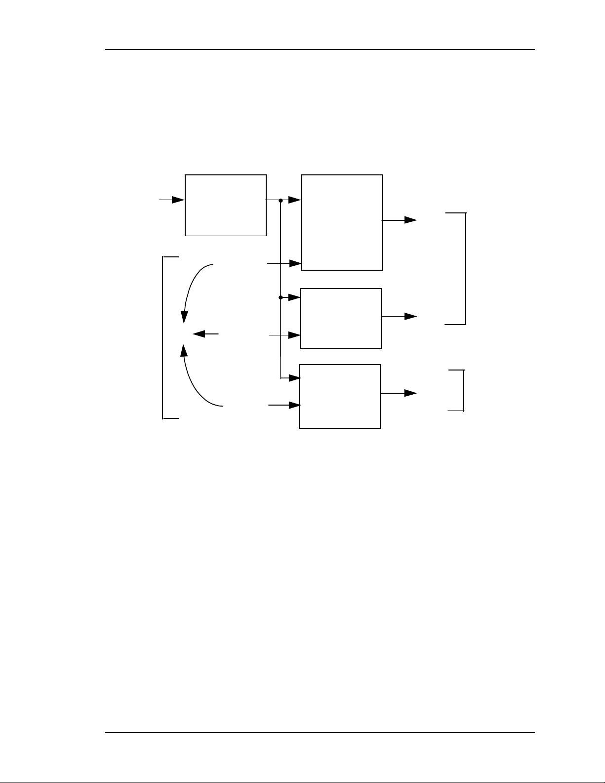
AC INPUT
220-240vac
50Hz
From
System
Controller
POWER
FACTOR
CORRECTION
/FANENBL
J502
Model 330. Model 340SC = +25V/80a; Model 370SC = +30V/100a.
∇
/LVPSNBL
/ALENBL
Figure 2-3
System Power Supply Block Diagram.
STANDBY/
I/O CONTROL
+5v, +24v
LOW VOLTAGE
Power Supply
+5v,+6.3v,+-15v,
+24v,+48v,+107v
ARC LAMP
Power Supply
and Boost
+22v/68a
+170v/1.0a
∇
J502
J500
J503 (-)
J504 (+)
To
Backplane
To
Arc Lamp
Via
Ignitor
Normal system power-up (Electronics and Lamp):
1. Upon receipt of Power-On command, SCB pulls /FANENBL and
/ALENBL lines low.
2. +24V Standby and Arc Lamp power supplies turn on.
3. When Arc Lamp lights (run voltage sensed by a window comparator in the
SPS), SPS pulls /LAMPLIT line low.
4. When SCB senses /LAMPLIT low, SCB pulls /LVPSNBL line low.
5. Low voltage supplies turn on.
6. SCB senses +5V supply at correct level and enters normal program
sequence.
Lamp only power-up:
1. Upon receipt of Lamp-On command, SCB pulls /FANENBL and
/ALENBL lines low.
Model 330, 340SC and 370SC Service Manual 2–7
Page 20
Chapter 2—Functional Descriptions
2. +24V Standby and Arc Lamp power supplies turn on.
3. When Arc Lamp lights (run voltage sensed by a window comparator in the
SPS), SPS pulls /LAMPLIT line low.
4. SCB senses /LAMPLIT low and awaits further instructions.
Electronics only power-up:
1. Upon receipt of Electronics-On command, SCB pulls /FANENBL and
/LVPSNBL lines low.
2. +24V Standby and Low voltage supplies turn on.
3. SCB senses +5V supply at correct level and enters normal program
sequence, lamp can be turned on at any time.
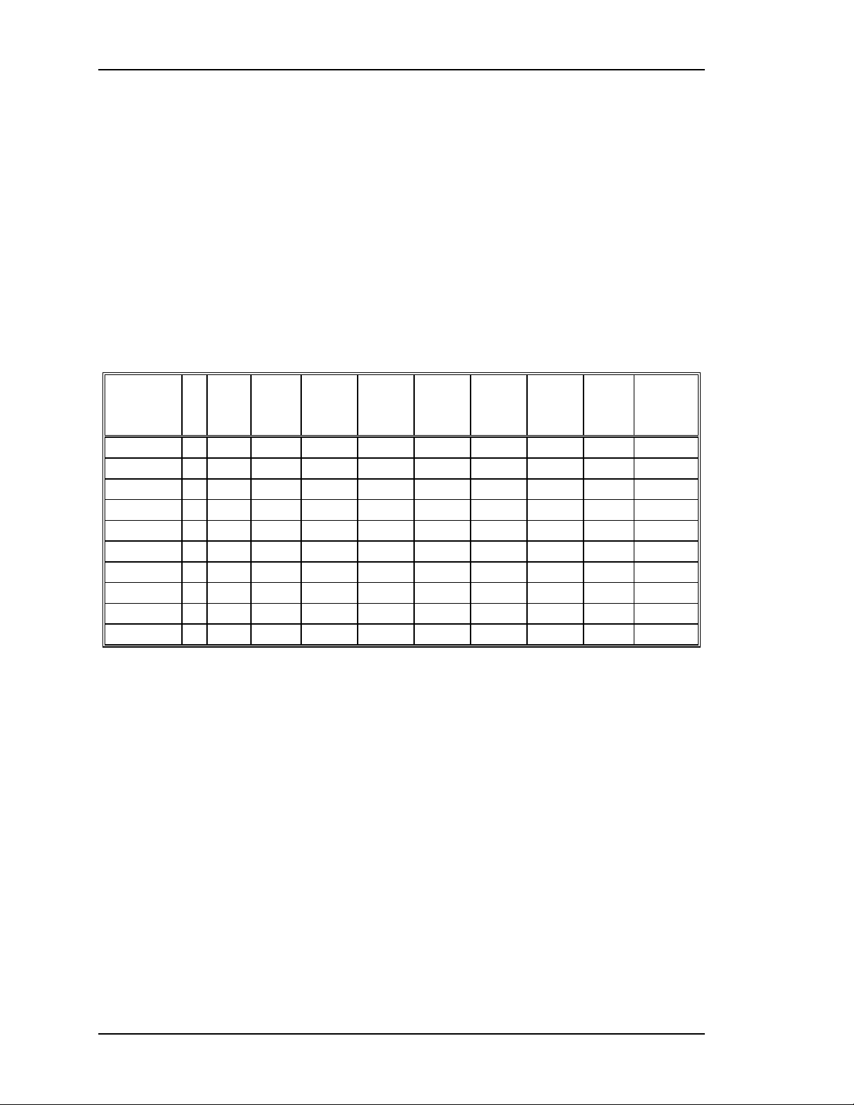
Table 2-1
VoltageFa
+5v
+5v Stb
+6.3v
+15v
-15v
+24v
+24v Stb
+48v
+107v
+170v
System Power Supply Voltage Distribution
HV
PS
n
CRT SCB HDB VDB VPB RTG VAB
Arc
Lamp/
Ignitor
2–8 Model 330, 340SC, and 370SC Service Manual
Page 21
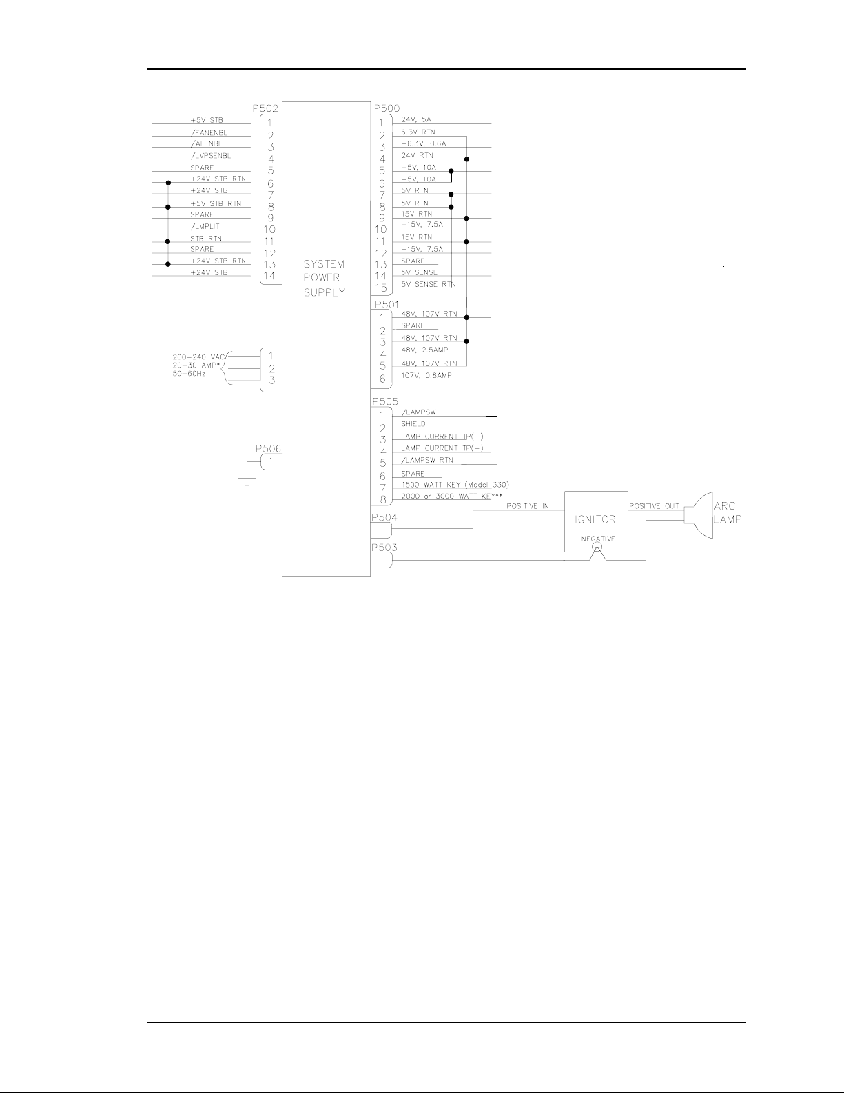
Chapter 2—Functional Descriptions
*Current depends on projector model (see Table 0-1 in Safety Chapter).
** Model 340SC = 2000 Watts; Model 370SC = 3000 Watts.
Figure 2-4
System Power Supply Input/Output Diagram
Arc Lamp Ignitor
The ignitor consists of a step-up power supply, a spark gap, and a transformer.
The Arc Lamp Ignitor is mounted under or next to the Arc Lamp. It provides the
high voltage pulse necessary to ignite the Xenon Arc Lamp that is the illumination
supply for the HJT Model 330, 340SC and 370SC projectors.
The System Power Supply’s Arc Lamp Supply section provides the necessary
voltage to activate the ignitor and to sustain the arc in the Arc Lamp once it has
been ignited. The SPS provides the power necessary to operate the ignitor.
The Ignitor is only active during the time between the Arc Lamp Power Supply
energizing and the Arc Lamp igniting. During steady state operation and when the
projector power is off, the ignitor is inactive.
Model 330, 340SC and 370SC Service Manual 2–9
Page 22
Chapter 2—Functional Descriptions
When the Arc Lamp supply first turns on, it supplies 170V to the ignitor. The
ignitor then senses this voltage, activates it’s on-board supply, and produces a
1µS, 38KV pulse to the Arc Lamp. This pulse strikes an arc in the lamp. The Arc
Lamp supply then provides the high current necessary to sustain the arc in the
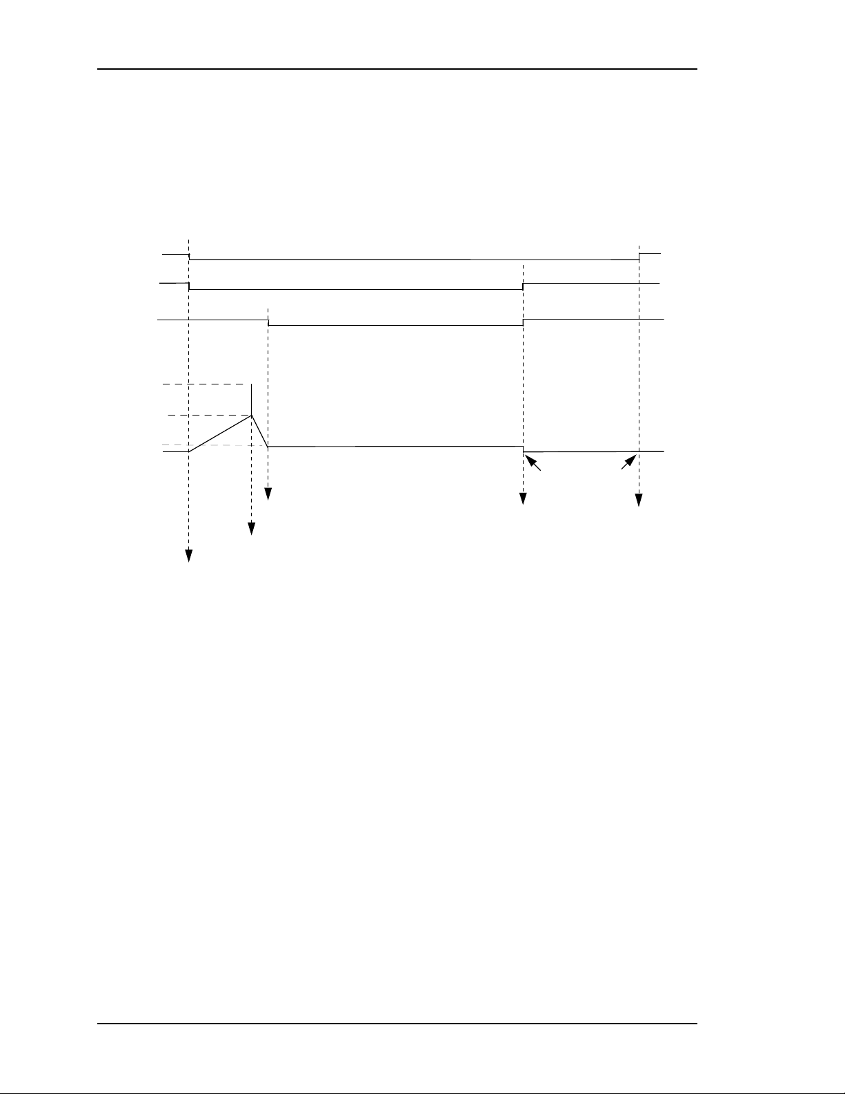
lamp. Refer to Figure 2-5 and the summary below for a description on the Arc
Lamp and Ignitor timing.
/FANENBL
/ALENBL
/LAMPLIT
38 KV
170V
22-30V
*
0V
1
2
3
4
5
6
ARC LAMP ON
IGNITOR FIRES
CPU TIME-OUT
5-10 MINUTES
LAMP-OFF
COMMAND
FAN DISABLE
LAMP-ON COMM A ND
*
22-30V depending on projector model.
Figure 2-5
Arc Lamp/Ignitor Timing Diagram Summary:
Arc Lamp Ignitor Timing Diagram
1. The operator powers Arc Lamp on. /ALENBL and /FANENBL from
System Controller Board are pulled low. SPS receives /ALENBL from
SCB and turns on the Arc Lamp PS.
2. Ignitor receives +170V boost voltage from the Arc Lamp PS.
3. Ignitor steps up the +170V boost voltage to a 1 µsec pulse, approximately
38KV.
4. Arc Lamp ignites from the 38kV pulse.
5. High current (about 68-100A depending on projector model) begins
through Arc Lamp and voltage drops to +22-30V (depending on projector
model).
6. /LAMPLIT signal goes to SCB to inform board that Arc Lamp is lit.
2-10 Model 330, 340SC, and 370SC Service Manual
Page 23
Chapter 2—Functional Descriptions
High Voltage Powe r Supply
The High Voltage Power Supply is a DC-DC converter (see Figures 2-6 and 2-7)
and is located on the left side of the CRT housing. It provides all necessary
voltages for the CRTs except the cathode drive, which comes from +107V from
the SPS.
Figure 2-6
Input power is +24V at 5A from the SPS. The input power is converted into the
High Voltage Power Supply
high voltage necessary to bias the CRTs.
The HVPS is controlled by an enable line (/HVEN) originating at the Video
Processor Board. This enable line is controlled by logic that turns the HVPS off
when there is a fault that could damage the CRTs. There are two (2) different
conditions that could damage the HVPS:
1. If the +5V supply to the VPB is interrupted, the control and protection is
compromised and the HVPS must be turned off.
2. If the cathode drive power is lost on one of the Video Amplifiers, the
cathode current cannot be controlled and the HVPS is turned off.
3. Further details regarding this logic can be found in the functional
description on the Video Processor Board in Section 2.6.4.
Model 330, 340SC and 370SC Service Model 2-11
Page 24
Chapter 2—Functional Descriptions
The HVPS provides several voltages to the CRTs:
Anode
Grid 1
Grid 2
Focus
+24v
GROUND
HDFOCUS
HDFOCUS RTN 8
VDFOCUS
/HVEN
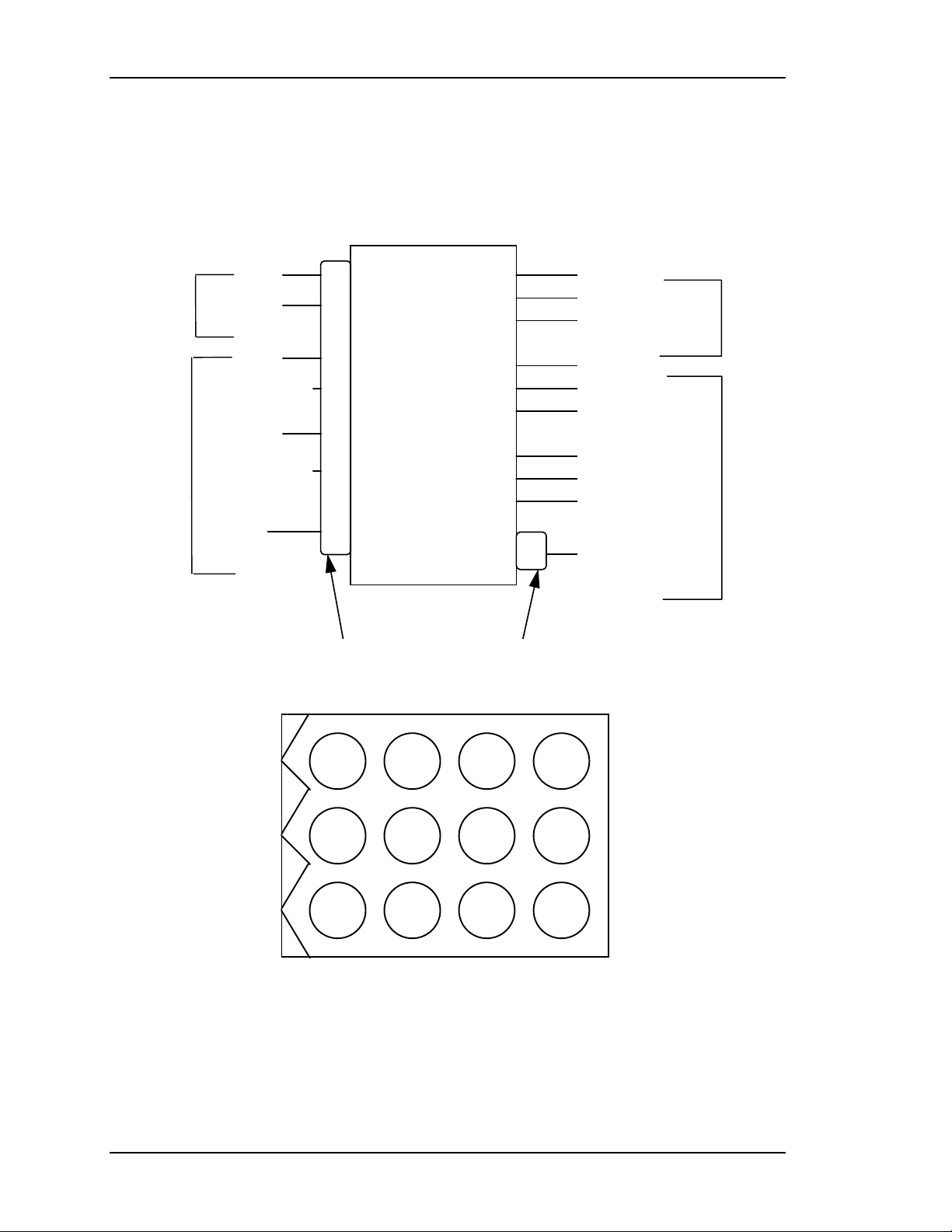
Figure 2-7
2
3
11
High
Voltage
12
9VDFOCUS RTN
7
Power and Control Connector
Power
Supply
6
(Pins 1,4,5,10 not used)
RED ANODE
GREEN ANODE
BLUE ANODE
RED FOCUS
GREEN FOCUS
BLUE FOCUS
RED G2
GREEN G2
BLUE G2
-200v
High Voltage Power Supply Input/Output Diagram
12369
11258
10147
Figure 2-8
2-12 Model 330, 340SC, and 370SC Service Manual
HVPS Power and Control Connector Jack, J603
Page 25

Chapter 2—Functional Descriptions
CRT anode voltages are not user controllable. They are fixed at 32KV with a
maximum output of 2.1mA total or 0.7mA per CRT. The anode voltage is the
primary acceleration voltage for the CRT. Other bias voltages (screen grid, G2,
and control grid, G1) are used to control the level of beam current. The anode
voltage is routed out of the top of the HVPS, into the CRT housing to three (3)
bulkhead connectors. From there, the anode wires on the CRTs route the anode
voltage directly to the CRT. The anode voltages are overvoltage and overcurrent
protected in the event of short circuits or CRT arcing.
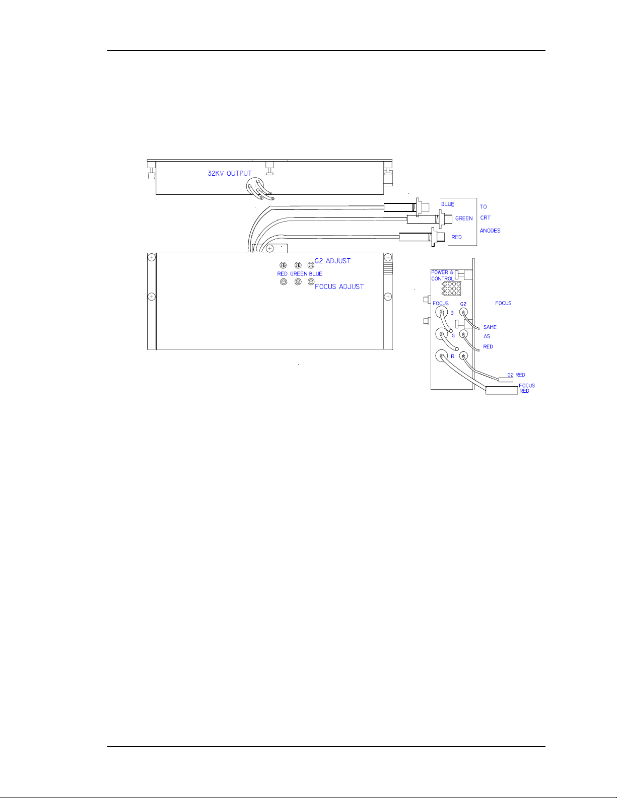
Focus voltage (called Electronic Focus) is a modulated DC voltage. The DC level
is set by the user during initial setup to focus the CRT electron beam. The
Electronic Focus controls are located on the left side of the HVPS (see appropriate
model Operator’s Manual). There are three (one for each color) ¾ turn pots for
adjusting the Electronic Focus. Of the six (6) pots found on the HVPS, the bottom
three (3) are for focus while the top three (3) are for G2 adjustment (Section 3.10).
The DC voltage is modulated within the HVPS using the HDFOCUS and
VDFOCUS input signals. VDFOCUS is the vertical dynamic focus signal, which
is a waveform with parabolic shape at the vertical sweep frequency. HDFOCUS is
the horizontal dynamic focus signal. It is a combination of the vertical dynamic
focus signal and a parabolic waveform at the horizontal sweep rate. These two (2)
signals are combined in the HVPS to form a composite dynamic focus signal.
Dynamic focus is necessary to ensure that the CRT electron beam is converged to
a point as the beam sweeps across the CRT face. Since the CRT faceplate is flat,
the raster sweep causes a varying path length for the electron beam. This means
the focus voltage must be varied as the raster is traced. Focus voltage cannot be
conveniently measured during normal operation.
G2 screen grid voltage is a DC voltage that is set by the user. The three (3)
adjustment controls, one for each color, consist of ¾ turn pots and are located on
the left side of the HVPS immediately above the focus controls. This voltage is set
during initial projector setup to adjust the black level on the screen (see
appropriate model Operator’s Manual). The G2 voltage sets the bias on the screen
grid of the CRT and is normally used to set the cutoff level. However, since the
HJT light valve requires a non-zero input to produce a just-cut-off image on the
screen, G2 is set to produce a slightly greater-than-black raster on the CRT. The
G2 is adjustable from 100V to 1400V individually by color. The actual operating
level will be near 1200V. G2 voltage cannot be conveniently measured during
normal operation.
-200V is the supply to the control grid (G1) of the CRTs through the Video
Amplifier Board. This voltage is not user controllable. The -200V is the only
output voltage from the HVPS that goes to the backplane of the projector to be
routed to the Video Amplifier, and uses the rear-most LED of the backplane LED
bar for indication.
-200V is the only convenient means of directly observing whether or not the
HVPS is turned on, either by observing the indicator LED on the backplane, or by
probing the control connector with a voltmeter.
Model 330, 340SC and 370SC Service Model 2-13
Page 26
Chapter 2—Functional Descriptions
As with the other indicators on that LED bar, the LED is in series with current
limiting resistor, so a lit LED indicates only the presence of a voltage, not
necessarily the correct voltage.
The control grid, G1, voltage is regulated to -81V during normal operation.
During blanking, G1 is pulled to -111V. When the CRTs are disabled for
protection, G1 is pulled to its maximum negative level of -200V, which can be
measured, at the control connector, pin 6.
2.5 Card Cage
The Card Cage provides support and protection for five (5) circuit boards, the
Phase Locked Loop and the optional Decoder Board in the HJT Model 330,
340SC and 370SC projectors. The five-(5) circuit boards are, from rear to front,
the VPB, RTG, SCB, VDB, and HDB. Each circuit board has it's own keyed slot.
A circuit board cannot easily be plugged into the wrong slot since the connectors
will not match up.
Horizontal Deflection Board (HDB) P/N 102523
Vertical Deflection Board (VDB) P/N 102521
System Controller Board (SCB) P/N 104668
Raster Timing Generator
and Phase Locked Loop
Video Processor Board
(RTG)
P/N 100568
(PLL)
(VPB) P/N 104672
and optional Decoder Board
Figure 2-9
Four (4) fans on the right side of the card cage cool the circuit cards in the card
Electronics Card Cage
cage. These fans are energized by the +24V standby power from the SPS. They
start when either the Arc Lamp or the electronics are powered up and run for
approximately five (5) minutes after the projector is shut down.
The five-(5) cards in the card cage are held into position by both the friction of the
connectors and by a circuit board retaining bar. The circuit board retaining bar
should always be installed during projector operation.
A lightweight top cover is included with the card cage. Eight (8) screws secure the
cover. The cover provides for direction of air flow and for physical protection of
the circuit cards contained in the card cage. The cover should always be installed
when the projector is in operation to ensure adequate cooling of the circuit cards
and to prevent foreign materials from falling into the electronics.
2-14 Model 330, 340SC, and 370SC Service Manual
Page 27
The card cage is hinged in the rear to allow it to be folded backward for access to
the CRT housing (when folding the card cage backward be sure that nothing is
plugged into the rear electronic jacks or the plugs could be severely damaged).
During normal operation, the card cage should be in its upright position to ensure
proper cooling of the CRT enclosure.
A holddown screw is provided to secure the card cage and prevent it from rotating
backward during shipping or when the projector is mounted in an upwardpointing position. The holddown screw is located on the lower, front, right corner
of the card cage.
The rear panel of the card cage provides mounting for the projector controls. The
VPB, which receives all image and sync inputs, is secured to the rear panel by
four screws. The RS-232 control connectors and the IR receiver and repeater
inputs as well as the LED dot matrix status display are located on the lower left of
the rear panel. The projector model and serial numbers are also found on the rear
panel.
2.6 Circuit Boards
Chapter 2—Functional Descriptions
The Model 330, 340SC and 370SC projectors have a total of twelve (12)
accessible circuit boards. Seven (7) boards are located within the card cage
(Figure 2-9) and five (5) are located outside the card cage (Table 2-2).
Table 2-2
No. Description
Ignitor
1
Video Amp Boards (VABS)
3
Backplane
1
Each circuit board can be replaced individually except the Backplane board and
Circuit Boards Outside Card Cage
330
102083
103567
100571
340SC
102207
103567
100571
370SC
104475
103567
100571
the PLL. The PLL is replaced with the RTG as a unit. The Ignitor was previously
described in Section 2.4.2. The circuit boards covered in this Section are listed in
Table 2-3.
Table 2-3
Page
2-18 Raster Timing Generator
2-26 Horizontal Deflection Board (HDB)
2-34 Vertical Deflection Board (VDB)
2-44 Video Processor Board
Circuit Board
Circuit Boards
(RTG)
(VPB)
P/N
100568 and PLL
102523
102521
104672
and optional Decoder Board
2-55 Video Amplifier Board
2-58 System Controller Board
2-70 Backplane Board
(VAB)
(SCB)
103567
104668
100571
Model 330, 340SC and 370SC Service Model 2-15
Page 28

Chapter 2—Functional Descriptions
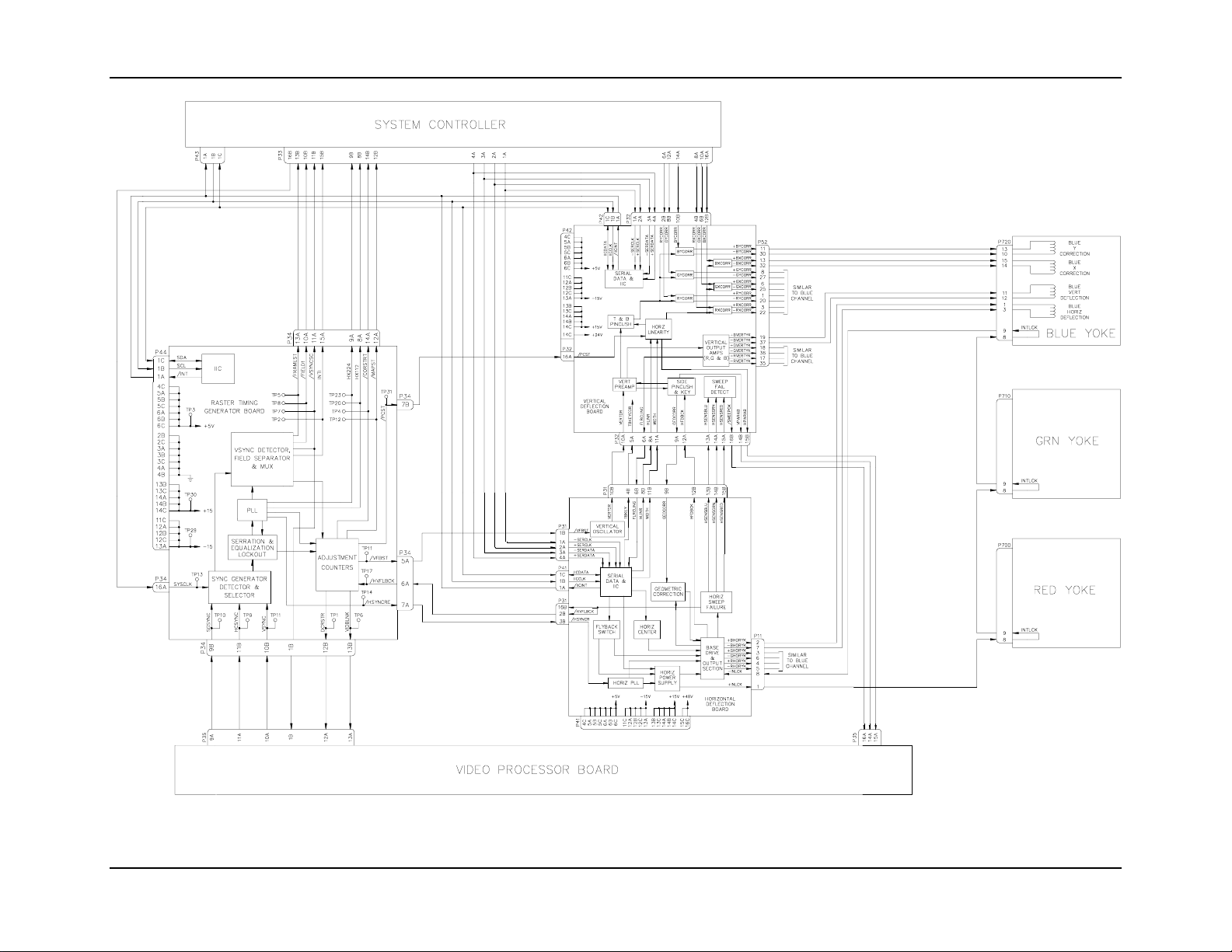
Figure 2-10 on the following page provides an overall view of how the raster is
produced. Details on the individual PCBs are provided in separate sections in this
chapter.
2-16 Model 330, 340SC, and 370SC Service Manual
Page 29
Chapter 2—Functional Description
Figure 2-10
Model 330, 340SC and 370SC Service Manual 2-17
Raster Generation Block Diagram
Page 30
Chapter 2—Functional Descriptions
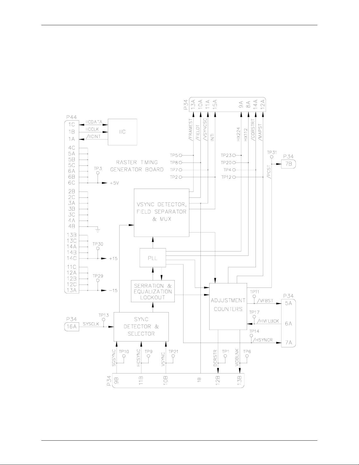
Raster Timing Generator Board (RTG) p/n 100568
The Raster Timing Generator board is located in the electronics card cage and plugs into
the backplane. It is the second board from the rear of the card cage and consists of a main
board and the PLL daughter board (see Figure 2-11). The PLL board must be installed for
the projector to operate.
Figure 2-11
2-18 Model 330. 340SC, and 370SC Service Manual
Raster Timing Generator Block Diagram
Page 31

The following functions are provided by the RTG:
Internal sync generation.
Sync detection and selection.
Serration and equalization pulse removal.
Timing clock pulse generation.
VSYNC separation and field detection.
Timing for several geometry and correction functions.
Serial communication with the SCB.
The block diagram ( see Figure 2-11) description, along with the I/O description in the
Chapter 2—Functional Description
Section following, provide information for module-level troubleshooting.
Sync Generator
The sync generator takes its input from the System Controller Board. The SCB provides a
4MHz clock signal, SYSCLK, which is used to generate a HDTV-like sync signal. The
internal sync signal generated is a 33.33KHz horizontal, 59.3Hz vertical, interlaced
signal. Because simply counting down from the 4MHz clock generates it, the actual
signal that is produced is a square wave signal. The square wave does not affect normal
operation of the projector but will cause a vertical bar to be generated on the screen when
the projector is operating on the internal sync with the DC restore timing set to BP or TL.
Sync Detector and Selector
The Sync Detector and Selector take inputs from the Video Processor Board. The VPB
sends the three (3) sync signals, SGSYNC (sync on green), HCSYNC (horizontal or
composite sync), and VSYNC (vertical sync only) of any polarity to the RTG. These are
the sync signals that come from the external source and are what the projector will genlock to when they are available. The sync selector uses a pre-determined priority to
determine which of these sync signals will be used, based on which signals are present at
the input.
The pre-determined priority to determine which sync signals used is:
1. Separate H and V sync will be used if both are available on their respective sync
inputs,
2. Composite sync on the HSYNC input will be used if available and no sync signal
is present on the VSYNC input,
3. Composite sync on the green image input will be used if no coherent sync signal
is available on the HSYNC input.
If no external sync signal is detected on the three (3) sync input lines, the RTG will send
out a signal to the SCB via the IIC interface indicating that there is no sync present
(/External Sync Detect). The SCB will then make a determination whether or not to
command the RTG, via the IIC interface, to select internal sync (Internal Sync Forced).
The selected sync signal(s) is inverted, if necessary, to provide the negative-going sync
signal needed by the downstream circuits.
Model 330, 340SC and 370SC Service Manual 2-19
Page 32

Chapter 2—Functional Descriptions
Serration and Equalizati on Lockout
The Serration and Equalization Lockout takes a composite sync signal and removes any
equalization and serration pulses from it. The Model 330, 340SC and 370SC projectors
do not require these pulses to operate. Removal of the serration and equalization pulses
provides a faster, more reliable response to the vertical sync and subsequent relock to
horizontal sync. This circuit uses the 4xHsync clock that is generated in the PLL to delete
any sync information present in the center portion of the incoming horizontal waveform.
Phase Locked Loop
The PLL receives horizontal sync stripped of the serration and equalization pulses from
the Serration and Equalization Lockout circuit.
The Horizontal Sync signal is fed to horizontal frequency decoder which uses a
frequency/voltage circuit to pre-tune the VCO of the PLL to ensure proper locking. The
Horizontal Frequency Decoder also provides a count of the number of horizontal lines per
frame. The H count is then sent via the IIC interface, to the SCB (HCOUNT). The SCB
uses this information to set up the correction and overlay maps and to calculate the H
frequency.
The PLL takes in the horizontal sync signal and generates a clock signal that is a square
wave of 224 times the horizontal frequency. The PLL will perform this function over the
entire range of horizontal frequencies, 15KHz to 90Khz. It will maintain that signal over
the full period of the raster including the vertical sync pulse. Counters in the PLL circuit
also provide clock signals with frequencies of Hx112, Hx4, Hx2, and Hx1. These clock
signals are square wave signals and are phase-coherent with respect to the H sync signal.
The Hx224, Hx112, and Hx1 signals are used on both the RTG and the SCB for timing of
corrections and raster adjustment. The signals that go to the SCB are Hx224, Hx112
(clock signals), and /HSYNCR (regenerated HSync, a negative-going pulse signal that is
timed to be on the leading edge of the Hx1 clock). The Hx4 and Hx2 clocks are used
exclusively on board the RTG for sync detection and timing.
Control of phase noise is critical—jitter will translate into a "smearing" of the projected
image. Therefore, if the PLL loses lock, the /Phase Lock signal is sent to the SCB via the
IIC interface. The SCB then makes a decision based on that information.
VSYNC Detector, Field Separator, and Mux
The VSync detector uses the Hx2 clock signal to detect the vertical sync signal from the
composite external sync signal that arrives on either the HSYNC input or the sync-ongreen input.
The field separator determines whether or not the signal is interlaced and, if so, which
field is currently being displayed. This information is sent to the SCB as the signals INTI
(interlace indication, high if interlaced), /FIELD1 (low when the field number 1 is
current), and /FRAMEST (indicates the beginning of a new frame).
The mux takes the external Vsync and field signals and multiplexes them with the
internal sync signal to select which will be used. The multiplexed Vsync signal is pulse-
2-20 Model 330. 340SC, and 370SC Service Manual
Page 33

Chapter 2—Functional Description
shaped to be three (3) horizontal periods in length. This signal, /VSYNCSC (pulseshaped vertical sync) is then sent to the SCB and the VPB.
Adjustment Counters
The adjustment counters implement the following timing functions:
Left side, right side, top side, and bottom side blanking.
Vertical and horizontal timing for convergence correction and overlay.
Pincushion and linearity correction timing.
Vertical phase.
DC restore timing.
The four-(4) sides' blanking adjustments are accomplished by counting from the
regenerated H and VSYNC signals respectively. Each adjustment is independent of the
others. Vertical blanking is accomplished by counting a specified number of horizontal
lines after the vertical sync signal out of the VSYNC Mux. The top blanking counts the
commanded number of lines then unblanks the picture. The bottom blanking counts the
commanded number of lines then blanks the image.
Horizontal blanking is accomplished by counting a specified number of Hx224 clock
pulses after the regenerated HSYNC pulse, /HSYNCR). The left side blanking counts the
commanded number of clock pulses then unblanks the image. The right blanking counts
the commanded number of clock pulses then blanks the image. The outputs from these
counters are combined with a signal indicating PLL lock, into a composite blanking
signal VIDBLANK (high when the image is to be blanked) that is sent to the VPB. The
user selects the actual position of the four sides' blanking by adjusting from the remote
control.
The SCB calculates the number of clock pulses to count for each of the four sides based
on the input from the user, and sends those numbers to the appropriate counters via the
IIC serial communication bus signals LBlank, RBlank, TBlank, and BBlank.
Adjustment counters also generate the convergence correction and overlay address
generators’ timing signals. The correction bit-map address counter's MAPST (timing
pulse to tell the correction and overlay address generators to start a new frame) timing
pulse is generated by counting the commanded number of /HSYNCR pulses since the
vertical deflection flyback start pulse. The /CORSTRT (signal that indicates to the SCB
when to start the correction and overlay address generators counting) timing signal is a
pulse signal sent to the SCB. Its timing is determined by counting the commanded
number of Hx224 pulses after the /HSYNCR signal.
The position of the overlays (including menus and test patterns) and correction maps is
controlled automatically in the vertical direction. In the horizontal direction, the user
controls the position via the MENU POSITION selection under the TIMING SETUP
MENU. This circuit also determines the phase between the regenerated HSYNC and the
HV Flyback from Deflection. This value is read by the SCB over the IIC bus.
The pincushion and linearity correction timing signal is a pulse signal called /PCST that
is sent to the Vertical Deflection Board. The signal is generated using the same timing
Model 330, 340SC and 370SC Service Manual 2-21
Page 34

Chapter 2—Functional Descriptions
method as the /CORSTRT signal but has a separate command from the SCB. It controls
the timing of the top and bottom pincushion correction, top and bottom keystone
correction, and horizontal linearity correction. The signal timing is selected by the user
and controlled by the SCB. Adjusting P
controls it.
Vertical phase adjustment is accomplished by timing the /VFBST (vertical start) signal
with respect to the regenerated vertical sync signal. This signal is generated by counting a
commanded number of horizontal lines after the vertical sync signal /VSYNCSC. The
signal timing is selected by the user and controlled by the SCB. It is controlled by
adjusting PHASE using the up/down arrows.
DC restore timing determines the point in time that the signal is clamped and the DC
restore (Section 2.6.4, Video Processor Board) function is accomplished. The user has
three (3) choices from which the DC restore timing can be selected. These are Backporch
(BP), Tri-level (TL), and Sync-tip (ST). The choices are selected in the SL column of the
C
HANNEL LIST
The DC restore timing counts a preset number of Hx224 clock pulses after the HSYNC
under the C
HANNEL MENU
signal leading edge. ST will clamp and DC restore during the time that the HSYNC pulse
is active. ST clamping is timed with respect to the leading edge of the HSYNC pulse. It is
seldom used but is necessary when there is no back porch to clamp on (image starts
immediately after the sync pulse). BP will clamp and DC restore shortly after the HSYNC
pulse. BP clamping is timed with respect to the trailing edge of the HSYNC pulse. The
timing is calculated to be on the back porch of the signal (after the sync pulse but before
the image begins). This is the most frequently used clamp timing.
INCUSHION POSN
under the T
(Figure 5-1, Menu Structure).
IMING SETUP MENU
The default setting for the DC restore timing is BP when a new channel is set up. TL
clamping occurs significantly after the HSYNC pulse. The purpose of TL timing is to
provide DC restore timing that is compatible with the Tri-level type sync used with
HDTV signals. Like BP, TL clamping is timed with respect to the trailing edge of the
HSYNC pulse. The output of the Synctip/Backporch circuit is a pulse signal (DCRSTR)
going to the VPB.
Serial Communication
The RTG uses only the IIC bus for serial communication with the SCB (Section 2.6.6).
The information transferred over the IIC bus is indicated below (I = input to RTG, O =
output from RTG). A change in output data generates an interrupt pulse.
Table 2-4
I/O
I
I
I
I
I
IIC BUS Information
Information
Priority Select
Description
Commanded sync selection priority
(always fixed as described above).
Vertical Flyback Start Delay Commanded V phase.
Map Start Delay
Commanded timing for vertical positioning
of correction map.
L Blank
R Blank
Commanded position of left blanking.
Commanded position of right blanking.
2-22 Model 330. 340SC, and 370SC Service Manual
Page 35

Chapter 2—Functional Description
O
O
O
O
T Blank
I
I
I
B Blank
/STBP
Commanded position of top blanking.
Commanded position of bottom blanking.
Command for DC restore timing on either
leading or trailing edge of sync pulse.
DC Restore Delay
I
Commanded timing of DC restore after
reference edge of sync pulse.
Internal Sync Forced
I
I
I
Correction Start Delay
Pincushion Start Delay
Command to force internal sync select.
Commanded H phase of correction map.
Commanded H phase of pincushion, keystone,
and linearity correction.
2H Sync Enable
I
I
Shifted Sync Enable
/External Sync Detect
HCount
/Phase Lock
Phase Count
Command determines path of H sync signal.
Command determines path of H sync signal.
Is an external sync available.
Count of H lines per frame.
Indication of PLL lock.
Indication of phase difference between
HSYNC and HFlyback.
Raster Timing Generator I/O
This section provides a description of the inputs to and outputs from the RTG. The I/O
description are arranged by the source/destination of the signal and so the assemblies
communicated with are used as the primary heading of each group of signals and then are
further subdivided into inputs and outputs. In each case, the signal's direction is noted,
with input referring to an input to the RTG, and output to an output from the RTG. (e.g.:
under System Controller Board “Input”; SYSCLK refers to the signal SYSCLK that is an
input to the RTG from the System Controller Board). When test points are provided for
the I/O they are noted.
Table 2-5
Inputs
SYSCLK 4 MHz clock signal for derivation of internal HDTV sync signal.
IICCLK
Outputs
/IICINT
/Hx224
Raster Timing Generator I/O Signals
System Controller Board
Description
(TP 13)
IIC clock line. Unidirectional clock line for control of
synchronous data transfer over IIC data bus.
Description
IIC interrupt line. Signal line for slave boards to inform the SCB
(master) that there is data to be transferred. Master then polls
slaves to determine the source of the interrupt.
Square wave signal 224 X the horizontal frequency for overlay
address generator clocking. (TP 23)
Model 330, 340SC and 370SC Service Manual 2-23
Page 36

Chapter 2—Functional Descriptions
/Hx112
112 times the horizontal frequency for convergence and Z axis
correction address generator clocking. (TP 20)
/CORSTRT Signal used to start the convergence and overlay address
generators during each horizontal sweep. (TP 4)
/FRAMEST Indicates the beginning of a frame. Used in the SCB for
counting vertical frequency. (TP 5)
INTI
/VSYNCSC Regenerated vertical sync signal, pulse shaped to 3 horizontal
Indicates when input source signal is interlaced. (TP 2)
lines in width. (TP 7)
/FIELD1
/MAPST
Low during field #1 of an interlaced input source. (TP 8)
Pulse signal to signal the overlay and correction address
generators to reset for a new frame. (TP 12)
I/O
IICDATA
IIC data line. Bi-directional serial line for synchronous data
Description
transfer between SCB and other circuit boards. See detailed
description for list of signals transferred and data direction.
Inputs
SGSYNC
Description
Stripped Green Sync is Sync-on-Green composite sync signal.
Video Processor Board
(TP 10)
HCSYNC
VSYNC
Outputs
DCRSTR
Horizontal/Composite Sync. (TP 9)
Vertical Sync used only for separate H and V sync. (TP 21)
Description
Pulse for DC restore timed to correspond to ST, BP, or TL.
(TP 1)
VIDBLNK Signal for image blanking from adjustment counters. (TP 6)
/VSYNCSC Vertical sync signal pulse for ILA bias sync. (TP 7)
Inputs
/HVFLBCK Signal representing horizontal flyback from the HDB. Used for
Description
Horizontal Deflection Board
determining H phase. (TP 17)
Outputs
/VFBST
/HSYNCRE Selected HSYNC signal. (TP 14)
Outputs
/PCST
Description
Signal to start the vertical retrace. (TP 11)
Vertical Deflection Board
Description
Signal to time the start of T/B pincushion and linearity
correction. (TP 31)
2-24 Model 330. 340SC, and 370SC Service Manual
Page 37

Inputs
+15V
Description
Power for the analog section of the RTG including the PLL.
System Power Supply
Chapter 2—Functional Description
(TP 30)
-15V
Power for the analog section of the RTG including the PLL.
(TP 29)
+5V
AGND
DGND
Power for the digital portions of the RTG. (TP 3)
Return for +/-15V, separated from DGND by an inductor.
Return for +5V, separated from AGND by an inductor.
Interlocks and Protection
This section describes the interactions between boards where one (1) board may cause
others to perform protection functions.
Input
None
Output
If the PLL falls out of sync, a signal indicating an out-of-lock condition (/PLOCK) will be
sent to the SCB.
Internal
When no external sync signal is present, the RTG will select it's internal sync signal, thus
preventing the need to provide another source for overlay generation.
Horizontal Deflection Board P/N 102523 (HDB)
The horizontal deflection board plugs into the electronics card cage and is the forwardmost card in the card cage.
The following functions are provided by the HDB:
Drive main horizontal deflection coils to provide horizontal raster
scan.
Horizontal raster centering.
Horizontal width adjustment.
Side pincushion correction.
L/R keystone correction.
Horizontal sweep reversal.
Horizontal phase adjustment.
Oscillator for vertical deflection.
The block diagram (see Figure 2-12) description and the I/O description, in the section
following, provide information to perform module level troubleshooting.
Model 330, 340SC and 370SC Service Manual 2-25
Page 38

Chapter 2—Functional Descriptions
Figure 2-12
Horizontal Deflection Board Block Diagram
Vertical Oscillator
The function of the vertical oscillator is to lock to the vertical signal, /VFBST, sent by the
RTG, and produce a pulsed output, VERTDR, of the same frequency. The /VFBST signal
initially is sent to a Frequency to Voltage converter to provide a program voltage to the
oscillator. This presets the oscillator frequency so the oscillator then is able to lock to the
incoming vertical sync signal.
2-26 Model 330. 340SC, and 370SC Service Manual
Page 39

The purpose for having an oscillator for the vertical sweep circuit is to maintain a sweep
Chapter 2—Functional Description
even in the event of loss of vertical sync signal to prevent damage to the CRT. The
vertical oscillator has a free-run frequency of approximately 35Hz when there is no input.
Horizontal Phase Locked Loop
The incoming signal, /HSYNCR initially is sent through a Frequency to Voltage
converter. The output from the F to V is used to provide a program voltage to the PLL, set
the horizontal phase adjustment range, and to set the frequency of the horizontal power
supply. The Horizontal PLL, like the vertical oscillator, takes the input pulsed signal,
/HSYNCR, from the RTG, locks to it, and produces a pulsed output of the same
frequency. The Horizontal PLL has the additional function of controlling the phase of the
output signal relative to the input signal. To do this, the horizontal PLL receives an input
from the SCB via the serial bus that indicates the desired phase relationship. The
incoming signal /HSYNCR is then compared with the flyback pulse (derived separately
from the /HVFLBCK signal listed in the I/O section) to measure the phase relationship.
To control horizontal phase, the operator presses the PHASE button on the remote
control, then adjusts phase with the left and right arrow keys. As with the vertical
oscillator, the Horizontal PLL provides for a minimum free-run frequency in the event of
loss of horizontal sync signal. That frequency is approximately 12.5kHz.
Horizontal Centering
Horizontal centering of each raster (R, G, and B) is accomplished by applying a direct
current bias to each horizontal deflection coil. The DC comes from a programmable
current source that is in series with the main deflection coil. The current source is capable
of providing either positive or negative polarity. Control input to the current sources
comes from the SCB via the serial interface. Pressing the POS (Position) button on the
remote control, then selecting the desired color can independently control the centering of
each individual color. The left and right arrow keys are then pressed to adjust horizontal
position. When controlling the position, Green is a master, i.e.: when Green is selected,
all three-(3) colors move. Red and Blue are independent.
Horizontal Power Supply
The horizontal power supply is a switching power supply that provides an output voltage
proportional to the horizontal frequency and width. The variable output of the power
supply is a negative voltage providing a sink for the horizontal deflection current. The
trace speed of the CRT spot will be determined by the voltage applied across the
deflection coil. The voltage at the power supply output directly determines this in turn. So
when the output from the power supply increases, a given width of raster can be obtained
in a shorter period of time, thus supporting a higher horizontal frequency. In addition to
providing for the maintenance of a constant raster size for varying frequency, a variable
power supply is also necessary for control of the raster width. The output voltage of the
horizontal power supply is controlled primarily by two (2) inputs.
Model 330, 340SC and 370SC Service Manual 2-27
Page 40

Chapter 2—Functional Descriptions
The first is an input derived from the F to V in the horizontal PLL circuit. This presets the
output of the supply to a voltage that will provide a nominal raster size for the horizontal
frequency applied.
The second input is provided by the SCB via the serial interface. This input allows
control of the raster width by the operator. To control the raster width, the operator
presses the SIZE button on the remote control. Pressing the left and right arrow keys then
controls the width. The three (3) rasters are not remotely controllable on an individual
basis. They can however, be set individually with respect to each other by adjusting the
cores of the variable inductors mounted on the yoke terminal boards (see appropriate
model Operator’s Manual).
Flyback Switching
Flyback switching, necessary to avoid overscan and excessive power consumption over
the wide range of horizontal frequencies covered, is accomplished using relays. When the
input source is changed, the relays are switched to change the response of the resonant
flyback circuit. Since horizontal flyback necessarily causes very high voltages, the relays
must not be switched while under load. When the SCB commands flyback switching to
occur, the switching circuit sends a signal to the GRN Horizontal sweep failure circuit to
turn off the CRT beams. It also sends a signal to the Horizontal Power Supply to turn it
off and shut down the horizontal sweep. The relays are then switched and the sweep and
CRT beams are allowed to return to normal. This sequence of events will occur each time
the input source to the projector changes, regardless of any line rate changes. There are
four frequency bands and flyback times that can be set. The frequency ranges and flyback
times are: 6.6uS @ 15-25.1kHz, 4.1uS @ 25-33.1kHz, 2.9uS @ 33-60.1kHz, and 2.4uS
@ 60-90kHz. Flyback switching is not manually controllable by the operator.
Geometric Correction
The HJT Model 330, 340SC and 370SC projectors provide the ability to obtain a
rectangular raster when shooting off-axis in the vertical direction from the screen. This
ability is provided by left/right keystone correction. A geometric correction signal,
GEOCORR, for controlling both the L/R keystone correction and the L/R pincushion
correction is obtained from the Vertical Deflection Board. The GEOCORR signal is a
periodic signal composed of a parabolic summed with a ramp signal, both at the vertical
frequency. This signal is used to vary the width of the horizontal sweep as the vertical
sweep progresses. It does this by modulating the negative voltage applied to the power
transistor, thereby modulating the horizontal width of the raster. The components of
GEOCORR, pincushion correction and keystone correction, are individually controllable
by the operator (see appropriate model Operator’s Manuals).
Output Section
The horizontal sync pulse signal produced by the Horizontal PLL is applied to the output
section to control the timing of the horizontal sweep. The output section includes the
power output transistor, base drive circuit, reversing connectors, and interlock circuit.
2-28 Model 330. 340SC, and 370SC Service Manual
Page 41

The three (3) horizontal deflection coils (B, G, and R) are driven in parallel by a single
Chapter 2—Functional Description
drive circuit and transistor. This is the reason for the inability to remotely control the
three (3) raster widths independently. Since the deflection coils are in parallel, it is
imperative that they all be connected prior to applying sweep voltage—the interlock
circuit ensures this. An output from the Horizontal Power Supply is sent, in series,
through all three (3) yoke connectors. This is part of the bias voltage used to operate the
base drive circuit for the output section. Thus, if any of the yoke connectors is not
connected, the output transistor will not turn on, and no horizontal sweep will be present.
There are two (2) output jumpers on the board, J500 and J501. Their function is to
reverse the direction of the current through the horizontal deflection coils for front and
rear projection. The output cable shall be connected to J501 for rear projection and J500
for front projection (Jumper Settings, Section 3.9).
Horizontal Sweep Failure Detection
Protection of the CRT from spot burns is accomplished by never allowing the CRT to
continue to have beam current when there is no deflection. To this end, the HDB has a
sensing circuit that detects when there is a loss of sweep that may cause CRT damage.
This circuit senses the horizontal flyback voltage and frequency. By sensing both
amplitude and frequency, the projector is able to maintain sweep over the widely varying
input conditions allowed and still protect the CRTs from damage. The flyback signal is
AC coupled and peak detected, then compared with a reference. As long as the flyback
amplitude and frequency are above the minimum allowed, the sweep detection outputs
(HSENSBLU, HSENSGRN, and HSENSRED) are pulled high. These signals are sent to
the VDB for processing.
Serial Communication
The HDB uses two (2) separate, interrelated serial data communication systems to
communicate with the SCB; the IIC bus, and a differential, synchronous data bus. The
information transferred over the serial busses is indicated below (I = input to HDB, O =
output from HDB). Also noted is whether the information is transferred over the IIC or
the serial bus. A change in output data generates an interrupt pulse.
Table 2-6
Bus
IIC
IIC
IIC
IIC
I
I
O
O
I/O
HDB Serial BUS Information
Information
Flyback switch select
Flyback switch pulse
Front/Rear indication
Floor/Ceiling
Two bits that select one of four flyback switching
Pulse signal that commands the flyback relays to
TTL level that indicates whether the projector is
TTL level that indicates whether the projector is
indication
Description
times (see detailed description)
switch.
in front screen mode (high) or rear screen
(pulled low).
in the upright mode (high) or inverted mode
(pulled low).
Model 330, 340SC and 370SC Service Manual 2-29
Page 42

Chapter 2—Functional Descriptions
Bus
IIC
I
I/O
Information
Serial data load
Description
Command to the serial data receiver that the
incoming data is to be read.
Serial
Serial
I
I
HPHASE
HLINR
Commanded horizontal phase of picture.
Commanded amount of overall H linearity
correction.
Serial
I
TBKEY
Commanded amount of top and bottom Keystone
Correction.
Serial
Serial
Serial
Serial
I
I
I
I
HCENTBLU
HCENTGRN
HCENTRED
WIDTH
Commanded horizontal position of blue raster.
Commanded horizontal position of green raster.
Commanded horizontal position of red raster
Commanded width of raster
Horizontal Deflection Board I /O
This section provides a description of the inputs to and outputs from the HDB. The I/O
description are arranged by the source/destination of the signal and so the assemblies
communicated with are used as the primary heading of each group of signals and then are
further subdivided into inputs and outputs. In each case, the signal's direction is noted,
with input referring to an input to the RTG, and output to an output from the HDB. (e.g.:
under Raster Timing Generator 'Input'; /VFBST refers to the signal /VFBST that is an
input to the HDB from the Raster Timing Generator). When test points are provided for
the I/O they are noted.
Table 2-7
Inputs
IICCLK
Horizontal Deflection Board I/O Signals
System Controller Board
Description
IIC clock line. Unidirectional clock line for control of synchronous data
transfer over IIC data bus.
+SERCLK
Serial data transfer clock (+). Unidirectional, differential clock line from
SCB to other circuit boards. Used for synchronous control of serial
communication over SERDATA data lines.
-SERCLK
Inputs
+SERDATA Serial data transfer. Unidirectional, differential, synchronous serial data
Serial data transfer clock (-).
System Controller Board
Description
communication line. Used for transferring data from SCB to other
circuit boards. Uses SERCLK and IIC for control of receiver.
-SERDATA Serial data transfer
Outputs
/IICINT
Description
IIC interrupt line. Signal line for slave boards to inform the SCB (master)
that there is data to be transferred. Master then polls slaves to
determine the source of the interrupt.
I/O
2-30 Model 330. 340SC, and 370SC Service Manual
Description
Page 43

Chapter 2—Functional Description
IICDATA
IIC data line. Bi-directional serial line for synchronous data transfer
between SCB and other circuit boards. See detailed description for
list of signals transferred and data direction.
Inputs
/VFBST
/HSYNCR
Outputs
/HVFLBCK Pulse signal representing horizontal flyback used to determine phase of
Description
Signal to control the vertical oscillator frequency and retrace timing
Regenerated horizontal sync signal
Description
Raster Timing Generator
image
Inputs
GEOCORR
FLRCLING TTL level indicating whether or not raster is inverted
Outputs
VERTDR
HLINR
HFDBK
WIDTH
TBKEYCOR DC voltage representing commanded top and bottom keystone correction
HSENSRED DC voltage, high when flyback pulse for red yoke is present at normal
Description
Periodic signal for L/R keystone and L/R pincushion correction
Description
Pulse output from vertical oscillator.
DC voltage controlling horizontal edge linearity correction
DC voltage proportional to the H power supply output voltage
DC voltage indicating commanded width.
Vertical Deflection Board
frequencies.
HSENSBLU Similar to HSENSRED.
HSENSGRN Similar to HSENSRED.
Inputs
/INLCK
Outputs
+INLCK
Description
Return from series daisy-chain for sensing yoke connectors installed.
Description
Negative voltage supply from the horizontal power supply to the daisy-
Main Horizontal Deflection Coils
chained yoke connector interlock.
+BHORYK
Positive supply from the centering current source to the blue horizontal
main deflection coil.
-BHORYK
Return from the blue horizontal main deflection coil to the horizontal
deflection power transistor.
+GHORYK Similar to +BHORYK.
-GHORYK
+RHORYK
-RHORYK
Model 330, 340SC and 370SC Service Manual 2-31
Similar to -BHORYK.
Similar to +BHORYK.
Similar to -BHORYK.
Page 44

Chapter 2—Functional Descriptions
Inputs
+48V
+15V
-15V
+5V
GND
Description
Power for horizontal deflection
Power for the analog section of the HDB
Power for the analog section of the HDB
Power for the digital devices on the HDB
Return for HDB
System Power Supply
Interlocks and Protection
Input
None
Output
HSENSRED - Used to shut down the CRT beams in the event of horizontal sweep
failure.
HSENSGRN - Identical to HSENSERED.
HSENSBLU - Identical to HSENSERED.
Internal
+INLCK
Prevents the horizontal output section from being turned on when 1 or more
deflection coils not connected.
-INLCK
!
Part of +INLCK circuit.
!
Minimum Frequency on Oscillators and PLLs
!
Ensures that there will be a sweep in both the horizontal and vertical
directions when the sync pulse disappears. This is for protection of the CRT
phosphor.
Vertical Deflection Board P/N 102521(VDB)
The Vertical Deflection Board plugs into the electronics card cage and is the second
board from the front in the card cage.
The following functions are provided by the VDB:
Drive main vertical deflection coils to provide vertical raster scan for
all three (3) CRTs.
Drive all correction coils to provide convergence and geometry
correction.
Scan failure detection for all six main deflection circuits.
Vertical size adjustment.
Vertical linearity adjustment.
2-32 Model 330. 340SC, and 370SC Service Manual
Page 45

Vertical raster centering.
Top and bottom pincushion correction.
Top and bottom keystone adjustment.
Horizontal overall and edge linearity adjustment.
Left and right pincushion and keystone correction
Chapter 2—Functional Description
waveform generation.
Sweep reversal for normal and inverted operation.
Generation of wave forms used for dynamic focus.
The block diagram (see Figure 2-13) description, along with the I/O description in the
following section, provide information for module level troubleshooting.
Component numbering on the VDB, in general, follows the pattern that 2XX refers to
components for Green deflection, 3XX refers to Blue, 4XX refers to Red (e.g.: R428 is a
resistor in the red deflection amplifier). Likewise, the correction amplifiers are numbered
5XX for Green, 6XX for Blue, and 7XX for Red.
Model 330, 340SC and 370SC Service Manual 2-33
Page 46

Chapter 2—Functional Descriptions
Figure 2-13
Vertical Deflection Board
Vertical Preamps
The vertical preamps (B, G, and R) each generate a ramp signal with the frequency
determined by the incoming signal VERTDR from the Horizontal Deflection Board. The
ramps generated in the preamp section have their common amplitude set by the
commanded height and are corrected for vertical linearity (linearity is individually
adjustable by R211, R311, and R411 and raster height is individually adjusted by R228,
R328, and R428). The common raster height is adjusted by a signal sent from the SCB to
the VDB via the serial bus. To control height, the operator presses the SIZE button on the
remote control, then adjusts height with the up and down arrow keys. The ramp
by the red preamp is used elsewhere in the VDB for the generation of correction signals.
2-34 Model 330. 340SC, and 370SC Service Manual
generated
Page 47

Chapter 2—Functional Description
Vertical Amplifiers
The Vertical Amplifiers take the ramp signals generated by the Vertical Preamps and
provide further modification prior to driving the vertical deflection coils. Individual
centering signals, set by the operator and controlled by the SCB are inserted in the
Vertical Output Amps to provide offset for each vertical sweep. The centering of each
individual color can be independently controlled by pressing the POS (Position) button on
the remote control then selecting the desired color. The up and down arrow keys are then
pressed to adjust vertical position. When controlling the position, Green is a master, i.e.
when Green is selected, all three (3) colors move. Red and Blue are independent. After
the centering signal is summed with the ramp signal, the result is amplified to produce the
required amplitude signal to drive the main vertical deflection coils.
The Vertical Amplifiers output is sent to jumpers for reversing the direction of the
vertical sweep for inverted operation. Jumpers J200, 300, and 400 are used for normal
operation while J201, 301, and 401 are used for inverted operation. A signal is sent to the
SCB indicating which mode of operation the jumpers are specifying.
Sweep Failure Detection
Current through the vertical deflection coil is sensed and that signal used to drive a sweep
indication circuit. There is one (1) circuit for each of Green, Blue, and Red. The sweep
indication circuit combines the vertical current signal with the horizontal flyback signal.
The signals from Green, Blue, and Red are then combined to produce a signal,
/SWEEPOK, that is sent to the VPB and indicates the health of all of the six (6) sweeps.
In addition to the /SWEEPOK signal, there are six (6) LEDs on the VDB which indicate
the presence of the individual sweeps. The LEDs indicating vertical sweep health
(LED200, 300, and 400) are driven by the vertical sweep signal alone. The horizontal
sweep signals affect both of the appropriate color LEDs (e.g.: if the Blue vertical sweep
fails, LED300 would turn off, but if the Blue horizontal sweep fails, LED300 and
LED301 would both turn off).
Side Pincushion and Keystone Correction
This circuit uses the ramp from the Red preamp to generate a variable amplitude
parabolic waveform for use in L/R pincushion correction. The Red ramp is also used to
generate a variable amplitude and polarity ramp for L/R keystone correction. Both the
L/R pincushion and keystone are controlled by the SCB sending a signal over the serial
bus. The operator can control the L/R pincushion by pressing the PIN button on the
remote control. The left and right arrow keys are then used to vary the amount of
pincushion applied. Pressing the KEY button on the remote control can control the L/R
keystone correction. The left and right arrow keys are then used to vary the amount of
keystone correction applied. The two (2) waveforms are then summed.
This signal is then multiplied by HFDBK from the HDB. The resultant signal,
GEOCORR, is sent to the HDB to modulate the horizontal width for side pincushion and
keystone correction.
Model 330, 340SC and 370SC Service Manual 2-35
Page 48

Chapter 2—Functional Descriptions
A form of the vertical frequency parabolic waveform that is derived from the red ramp is
also sent out to the VPB as VPARAB for use in the dynamic focus circuit.
Horizontal Linearity Correction
The Horizontal Linearity Correction section provides correction for both horizontal
overall linearity, and horizontal edge linearity. The WIDTH signal from the HDB and the
/PCST signal from the RTG are combined to form a periodic ramp signal with horizontal
frequency. The ramp signal is used to form a parabolic signal, again with horizontal
frequency. This signal and a signal commanded by the operator, HLINCORR, combine to
form a variable polarity and amplitude parabolic signal with horizontal sweep frequency.
This signal is used for overall horizontal linearity correction. The parabola and ramp
signals are also combined with the HLINLR signal, imported from the HDB, to produce
an S-curve signal of variable polarity and amplitude, also with horizontal sweep
frequency, to be used for edge linearity correction.
The operator can control each of these correction functions from the remote control by
pressing the LIN key for overall linearity adjustment, or the EDGE key for edge linearity
adjustment. The left and right arrow keys are then used to make the adjustments. The Scurve and parabola are then summed and sent to the Green, Blue, and Red X-correction
amplifiers where the corrections are applied to the correction coils. The parabolic signal
noted above, is also sent out to the VPB as HPARAB to be used in dynamic focus.
Top and Bottom Pincushion and Keystone Correction
A parabolic signal is borrowed from the horizontal linearity correction section for T/B
pincushion correction. It is combined with an operator command signal, TBPNCORR, to
produce a variable amplitude and polarity parabolic signal with horizontal sweep
frequency.
A ramp signal, also from the horizontal linearity section, is used for T/B keystone
correction. It is combined with an operator command signal, TBKEYCOR, to produce a
variable amplitude and polarity parabolic signal with horizontal sweep frequency.
Both the T/B pincushion and keystone are controlled by the SCB sending signals over the
serial bus. The operator can control the T/B pincushion by pressing the PIN button on the
remote control. The up and down arrow keys are then used to vary the amount of
pincushion correction applied. Pressing the K
the T/B keystone correction. The up and down arrow keys are then used to vary the
amount of keystone correction applied.
These two (2) signals are combined with the red ramp, having the frequency of the
vertical sweep, from the vertical pre-amp, to produce the top and bottom pincushion and
keystone correction waveform. This signal is then sent to the Green, Blue, and Red Ycorrection amplifiers. The operator can control the phase relationship of the T/B
pincushion, T/B keystone, and horizontal linearity, with respect to the picture.
button on the remote control can control
EY
To control these parameters, the operator selects PINCUSHION POSN from the TIMING
SETUP MENU under the MAIN MENU. The left and right arrow keys are then used to
vary the position of the corrections.
2-36 Model 330. 340SC, and 370SC Service Manual
Page 49

Chapter 2—Functional Description
Correction Amplifiers
There are six (6) correction amplifiers. Each one receives a real-time convergence
correction signal:
RXCORR.
RYCORR.
GXCORR.
GYCORR.
BXCORR.
BYCORR, from the SCB convergence section.
The X-correction amplifiers, R, G, and B, also receive the horizontal linearity signal. The
horizontal linearity signal is then combined with the appropriate color's X-correction
signal to produce a composite horizontal correction signal. The Y-correction amplifiers,
R, G, and B, receive the top and bottom pincushion and keystone correction signal. The
pin and key correction signal is then combined with the appropriate color's Y-correction
signal to produce a composite vertical correction signal. All six (6) correction signals are
then amplified by the correction amplifiers and are sent to their respective yoke coils.
Serial Communication
The VDB uses two (2) separate, interrelated serial data communication systems to
communicate with the SCB; the IIC bus, and a differential, synchronous data bus. The
information transferred over the serial busses is indicated below (I = input to VDB, 0 =
output from VDB). Also noted is whether the information is transferred over the IIC or
the serial bus. A change in output data generates an interrupt pulse.
Model 330, 340SC and 370SC Service Manual 2-37
Page 50

Chapter 2—Functional Descriptions
Bus
IIC
IIC
Serial
Serial
Serial
Serial
Serial
Serial
Serial
Serial
Table 2-8
I/O
O
VDB Serial Bus Information
Information
Front/Rear convergence
indication
Description
TTL level that indicates whether the X-
convergence is in front screen mode (high)
or rear screen (pulled low).
Serial data load
I
Command to the serial data receiver that the
incoming data is to be read.
VH
I
I
I
I
I
I
I
I
VCENTBLU
VCENTGRN
VCENTRED
TRAPCORR
LRPNCORR
TBPNCORR
HLINCORR
Commanded vertical height of picture.
Commanded vertical position of blue raster.
Commanded vertical position of green raster.
Commanded vertical position of red raster.
Commanded L/R keystone correction.
Commanded L/R pincushion correction.
Commanded T/B pincushion correction.
Commanded overall horizontal linearity
correction.
General I/O
This section provides a comprehensive description of the inputs to and outputs from the
VDB. The I/O description are arranged by the source/destination of the signal and so the
assemblies communicated with are used as the primary heading of each group of signals
and then are further subdivided into inputs and outputs. In each case, the signal's direction
is noted, with input referring to an input to the RTG, and output to an output from the
VDB. (e.g. under 'Raster Timing Generator', 'Input'; /PCST refers to the signal /PCST that
is an input to the VDB from the Raster Timing Generator). When test points are provided
for the I/O they are noted.
Table 2-9
Input
IICCLK
RXCORR
RYCORR
GXCORR
GYCORR
BXCORR
BYCORR
+SERCLK
-SERCLK
Vertical Deflection Board I/O Signals
System Controller Board
Description
IIC clock line. Unidirectional clock line for control of synchronous data
transfer over IIC data bus.
A 0-1 V signal from the bit-mapped memory on the SCB. 0.5V represents
no correction. This is a real time signal representing the X correction on
red.
Similar to RXCORR.
Similar to RXCORR.
Similar to RXCORR.
Similar to RXCORR.
Similar to RXCORR.
Serial data transfer clock (+). Unidirectional, differential clock line from
SCB to other circuit boards. Used for synchronous control of serial
communication over SERDATA data lines.
Serial data transfer clock (-).
2-38 Model 330. 340SC, and 370SC Service Manual
Page 51

+SERDATA Serial data transfer. Unidirectional, differential, synchronous serial data
Chapter 2—Functional Description
communication line. Used for transferring data from SCB to other
circuit boards. Uses SERCLK and IIC for control of receiver.
-SERDATA
Output
/IICINT
Serial data transfer.
System Controller Board
Description
IIC interrupt line. Signal line for slave boards to inform the SCB (master)
that there is data to be transferred. Master then polls slaves to
determine the source of the interrupt.
I/o
IICDATA
Description
IIC data line. Bi-directional serial line for synchronous data transfer
between SCB and other circuit boards. See detailed description for list
of signals transferred and data direction.
Raster Timing Generator
Inputs
/PCST
Description
Clock signal to start T/B pincushion, T/B Keystone, and horizontal
linearity correction.
Video Processor Board
Outputs
HPARAB
VPARAB
/SWEEPOK
Inputs
HSENSRED +15V indicates red horizontal flyback occurring at normal frequencies.
HSENSBLU Similar to HSENSRED.
HSENSGRN Similar to HSENSRED.
HFDBCK
Description
Parabolic signal at horizontal frequency for dynamic focus.
Parabolic signal at vertical frequency for dynamic focus.
Low indicates that all six sweeps are occurring at normal frequencies.
Horizontal Deflection Board
Description
Voltage representing amount of horizontal scan drive. Used for modifying
amount of side pincushion and keystone when changing horizontal
frequency.
WIDTH
Positive DC voltage representing commanded width of the raster. Used for
generation of horizontal linearity ramp and T/B pincushion correction
waveform.
VERTDR
HLINR
TBKEYCOR Voltage representing commanded top and bottom keystone correction.
Pulse signal at vertical frequency from the vertical oscillator on the HDB.
Voltage representing commanded horizontal linearity correction.
Model 330, 340SC and 370SC Service Manual 2-39
Page 52

Chapter 2—Functional Descriptions
Outputs
FLRCLING
Description
Low signal generated from jumper on connector J400 indicates non-
inverted operation.
GEOCORR
Outputs
+RVERTYK Supply line to the main vertical deflection coil (red) after going through
Output from L/R pincushion and keystone correction circuits.
Main Vertical Deflection Coils
Description
FLRCLING jumper plug.
-RVERTYK
Return from main vertical deflection coil (red) after going through
FLRCLING jumper plug.
+GVERTYK Similar to +RVERTYK.
-GVERTYK Similar to -RVERTYK.
+BVERTYK Similar to +RVERTYK.
-BVERTYK
Outputs
+RXCORR
-RXCORR
+RYCORR
-RYCORR
+GXCORR
-GXCORR
+GYCORR
-GYCORR
+BXCORR
-BXCORR
+BYCORR
-BYCORR
Inputs
+24V
+15V
-15V
+5V
GND
Similar to -RVERTYK.
Correction Coils
Description
Supply to the red X correction coil.
Return from the red X correction coil.
Similar to +RXCORR.
Similar to -RXCORR.
Similar to +RXCORR.
Similar to -RXCORR.
Similar to +RXCORR.
Similar to -RXCORR.
Similar to +RXCORR.
Similar to -RXCORR.
Similar to +RXCORR.
Similar to -RXCORR.
System Power Supplies
Description
Power to vertical deflection.
Power for analog portions of VDB.
Power for analog portions of VDB.
Power for digital devices on VDB.
Return for power on VDB.
2-40 Model 330. 340SC, and 370SC Service Manual
Page 53

Chapter 2—Functional Description
Interlocks and Shutdowns
Input
HSENSRED - Used to shut down the CRT beams in the event of horizontal sweep
failure.
HSENSGRN - Identical to HSENSERED.
HSENSBLU - Identical to HSENSERED.
Output
/SWEEPOK
Indicates whether or not all sweeps are occurring at or above a minimum frequency.
Used on the VPB to turn off the signal in the event of loss of sweep.
Internal
None
Model 330, 340SC and 370SC Service Manual 2-41
Page 54

Chapter 2—Functional Descriptions
Figure 2-14
Video Generation Block Diagram. This diagram provides an overall view of how the image is produced. Separate
sections of this chapter detail the individual PCBs.
2-42 Model 330, 340SC and 370SC Service Manual
Page 55

Chapter 2—Functional Description
Video Processor Board P/N 104672 (VPB)
The Video Processor Board (VPB) plugs into the electronics card cage.
It is the rear-most card in the card cage. The VPB is the only card in the card cage
that is held in by fasteners. There are four screws that tie the input tray to the rear
panel of the card cage. The input tray is an aluminum panel that attaches to the
VPB input BNC connectors. The input tray is a separate assembly and is not
included with the VPB when a new or repaired board is shipped.
The following functions are provided by the VPB:
Image and sync signal input.
Image and sync signal multiplexing.
Sync signal stripping.
Brightness and contrast control.
CRT protection logic.
Internal and external display multiplexing.
Image signal gamma correction.
LCLV uniformity correction.
LCLV bias.
Dynamic focus signal modification.
The block diagram (Figure 2-15) description, along with the I/O description in the
following section, provide information to perform module-level troubleshooting.
Model 330, 340SC and 370SC Service Manual 2-43
Page 56

Chapter 2—Functional Descriptions
Figure 2-15
Video Processor Board, Block Diagram
Decoder
The optional decoder is a daughter board installed on the VPB. Since the VPB can
only operate on an RGB/sync signal, use of the decoder is necessary in order for
the projector to use a composite signal. The decoder takes a composite (NTSC,
PAL, or SECAM) or S-Vid input and converts it into an RGB Sync signal for
2-44 Model 330. 340SC, and 370SC Service Manual
Page 57

Chapter 2—Functional Description
further use in the Video Processor Board. The IIC bus is used by the decoder to
select either Channel 3 (NTSC) or Channel 4 (S-Vid). The two (2) signals are
multiplexed together on the decoder board for export to the Video/Sync Mux.
Video/Sync Mux
The Video/Sync Mux selects one (1) of three (3) external inputs (RGB1, RGB2,
or Decoder) for use as the source for Image display and sync signals. The two (2)
external RGB Sync signals are selected by choosing RGB1 or RGB2 in the
C
HANNEL LIST
composite input) or SVHS (for the S-Vid input) from the same C
under the C
HANNEL MENU
. Selecting either CVID (for the
HANNEL LIST
uses the input from the decoder. The input to be used is selected by the System
Controller Board via the IIC bus. A green LED on the input panel is lit to indicate
which input is selected. The RGB image inputs are AC coupled while the sync
and decoder inputs are DC coupled. All inputs have a 75 ohm input impedance.
V & H Sync Strip
The vertical and horizontal sync signals are taken from the Video/Sync Mux and
individually peak and trough detected then pulse shaped to provide a TTL-level
signal representing the HSYNC and the VSYNC. Those signals are then sent out
to the RTG as the signals HSYNC and VSYNC and can be monitored on TP 14
and 15 respectively.
SG Sync Strip
The SG Sync Strip circuit looks at the green image signal between the video
MUX and the Brightness and Contrast Amp and sends the signal through a buffer
then peak detects the signal. The peak-detected signal then is compared with a
reference voltage to discriminate the sync signal from the video. The stripped sync
signal is then pulse shaped to provide a TTL representation of the composite sync
signal. The signal is sent out to the RTG as SGSYNC and can be probed at TP 13.
B, G, and R Brightness and Contrast Amplifiers
Each color of video (R, G, and B) uses an identical circuit. The Brightness and
Contrast amplifier serves to adjust the black and white levels of the external video
and also protects the CRT from excessive beam current by taking the beam
current signal from the Video Output Amp and comparing it with a reference. If
the beam current exceeds 1mA, the contrast command voltage is reduced to a
level that brings the CRT beam current back within bounds.
The Brightness and Contrast amplifier takes the contrast command signal after the
beam current limit circuit, and uses it to set the gain of the amplifier for contrast
control. Contrast is controlled by the SCB via the IIC interface. The operator
controls contrast level by pressing the C
arrows on the remote control. Green is a master and will control all three (3)
colors together. R and B are independent.
button and using the up and down
ONT
Model 330, 340SC and 370SC Service Manual 2-45
Page 58

Chapter 2—Functional Descriptions
Adding a DC offset to the output of the amplifier controls brightness. The
brightness is controlled by the SCB via the IIC interface. The operator controls
contrast level by pressing the B
the remote control. All three (3) colors are controlled together. During the DC
Restore interval when the BPCP pulse (measured at TP 10) is high, the output of
this amp is set to the nominal DC level.
On-Screen Switch
In the on-screen switch, the external video signal is multiplexed, in real time, with
internal video signals. The internal video signals used are full brightness, black, or
gray-scale/pyramid for a total of four (4) different signals that are multiplexed at
each point on the screen. The real-time multiplexing is used for the generation of
overlays and test patterns and is controlled by the switch logic. The output of the
on-screen switch can be monitored by test points TP5 (Red), TP6 (Green), and
TP7 (Blue).
Gamma Correction
button and using the up and down arrows on
RIGHT
After the On-Screen Switch the signal goes to the Gamma Correction section.
Gamma Correction is a non-linear gain stage that accounts for the non-linearities
of the ILA® Assemblies as well as for the CRT to produce a linear gray-scale on
the screen for a linear gray-scale input.
Switch Logic and Vi deo Enable
This section controls the overlays and test patterns on the screen as well as
providing protective functions.
Protection of the CRTs is accomplished by sensing dangerous conditions and
initiating protective functions. There are three (3) conditions that the projector
considers dangerous to the CRTs that are addressed in this circuit. Those three (3)
conditions are loss of sweep (any of the six), defective video amp, and loss of
power to the VPB.
When a loss of sweep occurs, the /SWEEPOK signal is released by the VDB and
is pulled high by the VPB. This initiates two (2) protective functions. First (1st)
is that the video signal is immediately cut off. This is the fastest way to reduce the
CRT beam current to prevent CRT damage. It is also the least effective since even
when there is no video signal to the video amp, there can still be beam current due
to a high G2 or other causes. Therefore, a second (2nd) function is initiated when
/SWEEPOK goes high. The enable signal to the video amps, /RENABLE,
/GENABLE, and /BENABLE is released by the VPB (all three [3] regardless of
which sweep is lost) and pulled high by the VAB. When this happens, it signals
the VAB to remove some of the bias voltage from its CRT. This further reduces
the possibility that there will be any beam current present during loss of sweep
and although more effective than removing video signal, it takes more time.
2-46 Model 330. 340SC, and 370SC Service Manual
Page 59

Chapter 2—Functional Description
A defective video amp is detected by the state of the /RVIDOK, /GVIDOK, and
/BVIDOK signals arriving from the VABs. A loss of +5V power to the VPB is
detected by observing it internally to this circuit. When any one of the VIDOK
signals goes high or a loss of +5V is detected, action will be taken to shut down
all three (3) CRTs.
Loss of +5V or defective VAB can potentially be more serious than loss of sweep.
Therefore, when one (1) of these conditions occurs, the same action will be taken
as for loss of sweep with the additional action of shutting down the HVPS. This is
done by releasing the /HVEN line allowing the HVPS to pull it high. Turning off
the HVPS is the most effective way of protecting the CRT but is also slowest—
explaining why other actions are taken in conjunction.
Switch logic is the portion of the circuit that controls what is seen on the screen at
any point at a given time. The SCB sends out signals as the raster is scanned.
These signals are outputs from the on-screen display bit-map. The signals
controlling on-screen video are BONSCRN, RONSCRN, GONSCRN,
VONSCRN, and VIDTEST. The signals are decoded in PALs on the VPB and
result in signals that control the on-screen switch multiplexers to display the test
patterns, text, and video.
Switch logic also takes in the signals from the RTG that control DC restore
(DCRSTR) and blanking (VIDBLANK) and distributes them throughout the VPB
and out to the VAB as the signals CLAMP and BLANKING.
RGB Sensitivity and Threshold Amplifier
Each color of video (R, G, and B) uses an identical circuit.
The video signal is taken from the output of the gamma correction section,
amplified, and sent off the VPB to the VAB via signals RVOUT (TP1), GVOUT
(TP2), and BVOUT (TP3).
The Threshold correction adds an offset to the signal in similar fashion to that of
the brightness control in the Brightness and Contrast Amp. The difference is that
the Threshold correction is, in general, not a pure DC signal, nor does the beam
current limit circuit affect it. Rather, it is a varying signal generated by the System
Controller Board in real time representing the correction necessary to account for
turn-on-point variations across the ILA® Assemblies. The signals from the SCB
are RTHRESH, GTHRESH, and BTHRESH. Also, when the clamp pulse signals
that it is time to do DC restore, the /BPCP signal removes the threshold correction
so that it will be reapplied after DC restore.
Sensitivity correction is applied by varying the gain of the amplifier. Like
threshold correction, the sensitivity correction signal that controls the gain is not,
in general, pure DC nor affected by beam current limit. It is a varying signal
generated by the System Controller Board in real time representing the correction
necessary to account for sensitivity variations across the ILA® Assemblies. The
signals for sensitivity correction from the SCB are RSENS, GSENS, and BSENS.
Model 330, 340SC and 370SC Service Manual 2-47
Page 60

Chapter 2—Functional Descriptions
Video signal cutoff is accomplished by pulling blanking to zero.
ILA® Bias
ILA® Assembly biasing is accomplished by generating a pseudo-square-wave
with frequency set by the operator. The SCB sends the information on bias
frequency via the IIC interface to the VPB. The operator can control the frequency
over a range of from 1.5KHz to 3.0KHz. Selecting ILA BIAS FREQ from the ILA
SETUP menu under the MAIN MENU controls the frequency. The bias square
wave is phase locked to the vertical sync to prevent any moving artifacts from
occurring on the screen due to bias.
The bias square wave is passed through an amplifier whose gain is set by the
operator via the SCB to vary the bias. This square wave is then turned into a
differential output in order to eliminate DC going to the ILA® Assemblies. The
outputs can be monitored at TP11 and 12 (RED), 1 and 14 (GRN), and 15 and 16
(BLU). Selecting BIAS W/O VIDEO from the ILA SETUP MENU under the
Main Menu controls the bias level for each individual color. The up and down
arrows are then used to vary the bias level.
BUS
IIC
IIC
IIC
IIC
IIC
IIC
IIC
Dynamic Focus Amplifier
The vertical focus amplifier takes the VPARAB signal from the VDB, amplifies it
and sends it out to the HVPS as the signal VDFOCUS for vertical dynamic focus.
The HPARAB signal, from the VDB, is multiplied by the VPARAB signal,
amplified, and also sent out to the HVPS as the signal HDFOCUS for horizontal
dynamic focus.
Serial Communication
The VPB uses two (2) separate, interrelated serial data communication systems to
communicate with the SCB; the IIC bus, and a differential, synchronous data bus.
The information transferred over the serial busses is indicated below (I = input to
VPB, O = output from VPB). Also noted is whether the information is transferred
over the IIC or the serial bus. A change in output data generates an interrupt pulse.
Table 2-10
I/O
I
I
I
I
I
I
I
VPB Serial BUS Information
Information
RENABLE
GENABLE
BENABLE
CH1SEL
CH2SEL
ILA® bias freq Information for setting bias frequency to ILA
Signal to cut off red.
Signal to cut off green.
Signal to cut off blue.
Selects RGB1 as input.
Selects RGB2 as input.
Description
Assembly.
SLOAD
Command to the serial data receiver that the
incoming data is to be read.
®
2-48 Model 330. 340SC, and 370SC Service Manual
Page 61

Chapter 2—Functional Description
IIC
IIC
IIC
BUS
Serial I
Serial I
Serial I
Serial I
Serial I
Serial I
Serial I
I/O
O
O
O
VIDOK
SWEEPOK
BEAMDET
Information
REDBIAS
GRNBIAS
BLUBIAS
RCONT
GCONT
BCONT
BRIGHT
Tells SCB that no VABs are reporting problems.
Tells SCB that all sweeps are operating.
Tells SCB that beam current limiting is occurring.
Description
Commanded amplitude of red LCLV bias.
Commanded amplitude of green LCLV bias.
Commanded amplitude of blue LCLV bias.
Commanded red contrast.
Commanded green contrast.
Commanded blue contrast.
Commanded brightness level.
General I/O
This section provides a comprehensive description of the inputs to and outputs
from the VPB. The I/O description are arranged by the source/destination of the
signal and so the assemblies communicated with are used as the primary heading
of each group of signals and then are further subdivided into inputs and outputs. In
each case, the signal's direction is noted, with input referring to an input to the
RTG, and output to an output from the VPB. (e.g.: under Raster Timing Generator
'Input'; VSYNC refers to the signal VSYNC that is an input to the VPB from the
Raster Timing Generator). When test points are provided for the I/O they are
noted.
Table 2-11. Video Processor Board I/O Signals
System Controller Board
Input
IICCLK
Description
IIC clock line. Unidirectional clock line for control of
synchronous data transfer over IIC data bus.
BONSCRN
Along with RONSCRN, GONSCRN, VONSCRN,
VIDBLANK, and DCRSTR (the later two on from the
RTG board) determines whether there is full brightness,
black, gray-scale, or external video presented in blue at a
given point on the screen.
RONSCRN
GONSCRN
VONSCRN
VIDTEST
Similar to BONSCRN.
Similar to BONSCRN.
Determines if internal test patterns will be shown.
Internal gray-scale video input information. Real time data 0V
to 1V.
RSENS
Sensitivity (Z-axis gain) correction information for red. Real
time data at 0V to 1V.
GSENS
BSENS
Similar to RSENS.
Similar to RSENS.
Model 330, 340SC and 370SC Service Manual 2-49
Page 62

Chapter 2—Functional Descriptions
RTHRESH
Threshold (Z-axis offset) correction information for red. Real
time data at 0V to 1V.
GTHRESH
BTHRESH
+SERCLK
Similar to RTHRESH.
Similar to RTHRESH.
Serial data transfer clock (+). Unidirectional, differential clock
line from SCB to other circuit boards. Used for
synchronous control of serial communication over
SERDATA data lines.
-SERCLK
+SERDATA
Serial data transfer clock (-).
Serial data transfer. Unidirectional, differential, synchronous
serial data communication line. Used for transferring data
from SCB to other circuit boards. Uses SERCLK and IIC
for control of receiver.
-SERDATA
Outputs
/IICINT
I/O
IICDATA
Serial data transfer.
System Controller Board
Description
Interrupt used to tell the SCB that the VPB has data to report.
Description
IIC data line. Bi-directional serial line for synchronous data
transfer between SCB and other circuit boards. See
detailed description for list of signals transferred and data
direction.
Raster Timing Generator
Inputs
VIDBLANK
Description
Along with RONSCRN, GONSCRN, BONSCRN, and
VONSCRN from the SCB, and DCRSTR, determines
whether there is full brightness, black, gray-scale, or
external video presented at a given point on the screen.
DCRSTR
Along with RONSCRN, GONSCRN, BONSCRN,
VONSCRN, from the SCB, and VIDBLANK, determines
whether there is full brightness, black, gray-scale, or
external video presented at a given point on the screen.
Outputs
SGSYNC
Description
Stripped Green Sync. The composite sync signal stripped from
the green channel
(if it exists) (TP13).
HSYNC
Horizontal Sync. This can be either just the horizontal sync, in
which case there will be a separate vertical sync, or
HSYNC can be a composite sync. (TP14)
VSYNC
Vertical Sync. This cannot be a composite sync signal. (TP15)
2-50 Model 330. 340SC, and 370SC Service Manual
Page 63

Chapter 2—Functional Description
Vertical Deflection Board
Inputs
VPARAB
Description
A periodic, positive-going, parabolic waveform with the
vertical scan frequency, used for dynamic focus.
HPARAB
A periodic, positive-going, waveform with the horizontal scan
frequency, used for dynamic focus.
/SWEEPOK
A TTL DC level signal indicating that, when low, indicates all
flybacks are occurring at or above a minimum frequency.
Video Amplifier Board
Inputs
RBEAM
Description
Voltage signal proportional to cathode current averaged over
several horizontal lines, in the red CRT. Voltage level is
+1mV/uA.
GBEAM
BBEAM
/RVIDOK
Similar to RBEAM.
Similar to RBEAM.
Open collector signal indicating the health of the red +100V
cathode supply.
/GVIDOK
/BVIDOK
Outputs
BLANKING Pulse signal output that is a buffered replica of the VIDBLANK input
Description
Similar to /RVIDOK.
Similar to /RVIDOK.
Video Amplifier Board
from the SCB. Indicates the commanded blanking interval during
the scan.
/BENABLE Logical connection of video amp, sweep, and power health
indications. TTL level output.
/RENABLE Identical to /BENABLE.
/GENABLE Identical to /BENABLE.
RVOUT
GVOUT
BVOUT
CLAMP
Red video output. 0V to 1V (TP1).
Green video output. 0V to 1V (TP2).
Blue video output. 0V to 1V (TP3).
Pulse signal output that is a buffered replica of the SCRSTR input
from the SCB. Indicates the commanded timing and duration of
the DC restore.
External Video
Inputs
RVIDCH1
RVIDCH2
GVIDCH1
GVIDCH2
Description
Red video input to channel 1.
Red video input to channel 2.
Green video with optional composite sync signal input to channel 1.
Green video with optional composite sync signal input to channel 2.
Model 330, 340SC and 370SC Service Manual 2-51
Page 64

Chapter 2—Functional Descriptions
BVIDCH1
BVIDCH2
HSYNCCH1 Horizontal or composite sync signal to channel 1.
HSYNCCH2 Horizontal or composite sync signal to channel 2.
VSYNCCH1 Vertical sync signal to channel 1.
VSYNCCH2 Vertical sync signal to channel 2.
COMPVID
LUM
CHROM
RTN
Outputs
+RLCLV
Blue video input to channel 1.
Blue video input signal to channel 2.
Composite video signal, pass through to decoder.
Luminance signal for SVHS, pass through to decoder.
Chrominance signal for SVHS, pass through to decoder.
Return for SVHS; pass through to decoder.
Image Light Amplifiers
Description
One half (½) of the differential pair providing a distorted square
wave to the red ILA. (TP 21)
-RLCLV
One half (½) of the differential pair providing a distorted square
wave to the red ILA. (TP 20)
+GLCLV
-GLCLV
+BLCLV
-BLCLV
Inputs
RED
GREEN
BLUE
SYNC
IICINT
CH3SEL
CH4SEL
VERT
Outputs
SCLK
SDATA
IICCLK
IICDATA
COMPVID
LUM
CHROM
RTN
Similar to +RLCLV. (TP 19)
Similar to -RLCLV. (TP 18)
Similar to +RLCLV. (TP 17)
Similar to -RLCLV. (TP 16)
Decoder
Description
Red video signal from decoder.
Green video signal from decoder.
Blue video signal from decoder.
Horizontal sync signal from decoder.
Interrupt signal from decoder, pass through to SCB.
Indicates to VPB that video input is composite.
Indicates to VPB that video input is SVHS.
Vertical sync signal from decoder.
Description
Single ended serial clock from serial communication bus to decoder.
Single ended serial data from serial communication bus to decoder.
IIC clock pass through to decoder.
IIC data pass through to decoder.
Composite video signal, pass through to decoder.
Luminance signal for SVHS, pass through to decoder.
Chrominance signal for SVHS, pass through to decoder.
Return for SVHS; pass through to decoder.
2-52 Model 330. 340SC, and 370SC Service Manual
Page 65

High Voltage Power Supply
Outputs
VDFOCUS
HDFOCUS
Description
Parabolic waveform of vertical frequency.
Parabolic waveform of horizontal frequency modulated by the
VDFOCUS waveform.
/HVEN
Enable signal for HVPS, used to shut down HVPS for CRT
protection.
System Power Supply
Inputs
+5V
GND
+15V
-15V
GND (TP 0) Return from analog components.
Description
Power supply to digital components.
Return from digital components.
Power supply to analog components.
Power supply to analog components.
Interlocks and Protection
Chapter 2—Functional Description
Input
/SWEEPOK
TTL high indicates that one or more of the sweeps, either horizontal or
vertical is not at or above the minimum amplitude and frequency. This will
cause a cutoff so that RVOUT, GVOUT, and BVOUT will be pulled low.
Additionally, /RENABLE, /GENABLE, and /BENABLE will be pulled high
resulting in shutdown of grid bias at the Video Output Boards. Also, the
SWEEPOK status bit will be transmitted to the SCB.
RBEAM
Signal representing average red CRT beam current at 1mV/1uA. At greater
than 0.7V, causes contrast and overlay intensity on all three colors to be
reduced.
GBEAM
Similar to RBEAM.
BBEAM
Similar to RBEAM.
/RVIDOK
High indicates low voltage at the +100V supply on the red Video Output
Board. This causes a low at the VIDOK status bit sent to the SCB over the IIC.
The /HVEN signal is allowed to go high shutting down the HVPS.
Additionally, a high cutoff signal is sent so RVOUT, GVOUT, and BVOUT
will be pulled low. /RENABLE, /GENABLE, and /BENABLE are also pulled
Model 330, 340SC and 370SC Service Manual 2-53
Page 66

Chapter 2—Functional Descriptions
high resulting in shutdown of grid bias at the Video Amplifier Boards. Also,
the SWEEPOK status bit will be transmitted as a low to the SCB.
/GVIDOK
Similar to /RVIDOK.
/BVIDOK
Similar to /RVIDOK.
Output
/HVEN
When either /RVIDOK, /GVIDOK, or /BVIDOK from the Video Amplifier
Boards is pulled high, or the +5V power on the Video Processor Board goes
low, /HVEN is pulled high. This results in the HVPS being disabled, thus
shutting down high voltage to the CRTs.
/RENABLE
High will cause grid voltages at the VAB to be pulled low shutting off the red
CRT beam. High will result from high on /RVIDOK, /GVIDOK, or /BVIDOK
from the VAB, +5V power going down on the VPB, or /SWEEPOK being
pulled high from the VDB.
/GENABLE
Similar to /RENABLE.
/BENABLE
Similar to /RENABLE.
Internal
None
Video Amplifier Board P/N 103567 or 103774 (VAB)
The Video Amplifier Board (VAB) is mounted on and plugs into the back of the
CRT. There are three (3) VABs—one (1) on each CRT and each is entirely
dedicated to servicing its respective CRT. The video amplifier boards are the last
stage of the video chain and provide all electrical connection to the CRTs except
for anode voltage and chassis bond.
The following functions are provided by the VPB:
Connection of all voltages to CRT.
Amplification of video signal.
Blanking.
DC restore.
Bias voltage control.
2-54 Model 330. 340SC, and 370SC Service Manual
Page 67

Chapter 2—Functional Description
Circuit failure detection.
Beam current sense.
Arc protection.
This section uses Figure 2-16 for reference. The description provides information
to perform module-level troubleshooting.
Figure 2-16
Video Amplifier Board, Block Diagram
Video Signal
The video signal comes directly from the VPB backplane connector via a coaxial
cable to the Video Amplifier Board and enters as VIN. The input signal will be a
maximum of 1Vpp. The video amplifier takes the input signal, amplifies and level
shifts it so that it will be a negative-going 75Vpp signal modulating the +84Vdc
black level, and applies this to the cathode of the CRT. In general, the 84Vdc
black level will be seen only during the DC Restore interval. Power for the video
amplifier is a locally derived 100V that is regulated down from the 107V input
from the SPS.
Failure Detection
The Failure Detection circuit senses the health of the video amp's 100V power
supply. When the 100V supply falls below about +64V, the normally low
/VIDOK signal is pulled high. The /VIDOK signal is then sent to the VPB.
Model 330, 340SC and 370SC Service Manual 2-55
Page 68

Chapter 2—Functional Descriptions
Beam Current Sense
The cathode current is sensed at the output of the video amplifier, then filtered
and amplified so that the output is a 1mV/1uA signal averaged over several
horizontal lines (the number of lines depending on the horizontal frequency). This
current sense signal is then sent to the VPB as the signal BEAM.
DC Restore
The DC Restore function is accomplished on the Video Amplifier Board when
commanded by the CLAMP signal from the VPB. When the CLAMP signal
arrives, the video signal has the offset values (Brightness and Threshold) removed
so that they will not be changed by the DC Restore circuit. The CLAMP signal
causes the output voltage to be sampled and compared to a reference. The
difference is sent to the input of the video amplifier to set the new black level for
the duration of the next horizontal line.
Arc Protection
The Arc Protection Circuit functions to drain off any energy that arrives at the
Video Output Amplifier board due to arcs on the cathode or grids. The arc energy
is suppressed by sending it directly to the HVPS chassis via the Arc Ground
terminal on the
board.
Blanking
The Blanking circuit operates by using the BLANKING signal from the VPB. The
BLANKING signal causes an amplifier to drive an AC coupled pulldown of
GRID1. G1 voltage is normally -81V but will be pulled down to -111V during the
blanking interval. The cathode voltage is unaffected by blanking.
Enable Circuit
The Enable circuit is controlled by the /ENABLE signal from the VPB. The
/ENABLE signal, when pulled high, causes both GRID1 and GRID2 to be pulled
low: G1 is pulled from nominal -81V to the disabled value of -200V, G2 is pulled
from its usual value of between +800V to +1200V to its disabled value of +15V.
Focus
The FOCUS voltage is a pass through from the HVPS to the CRT. It is not in any
way modified by the VOB.
Filament Supply
For the CRT Filament supply, 6.3Vdc from the System PS is simply filtered and
sent to the CRT.
2-56 Model 330. 340SC, and 370SC Service Manual
Page 69

Chapter 2—Functional Description
General I/O
This section provides a comprehensive description of the inputs to and outputs
from the VAB. The I/O description are arranged by the source/destination of the
signal and so the assemblies communicated with are used as the primary heading
of each group of signals and then are further subdivided into inputs and outputs. In
each case, the signal's direction is noted, with input referring to an input to the
VAB, and output to an output from the VAB (e.g.: under Video Processor Board;
'Input'; CLAMP refers to the signal CLAMP that is an input to the VAB from the
Video Processor Board). When test points are provided for the I/O they are noted.
Model 330, 340SC and 370SC Service Manual 2-57
Page 70

Chapter 2—Functional Descriptions
Table 2-11
Input
VIN
Video Amplifier Board I/O Signals
Video Processor Board
Description
COAX input from VPB via the backplane. Video signal of 1V peak-
to-peak maximum.
/ENABLE
TTL level DC signal which controls grid voltages. High causes G2
to be pulled to +15V and G1 to be pulled to -200V shutting off
the CRT beam.
CLAMP
TTL level pulse controlling DC restore. Restores black level of
cathode voltage to +84V.
BLANKING TTL level signal controlling video blanking. Pulls G1 to 30V below
normal voltage to turn off beam.
Outputs
BEAM
/VIDOK
Description
Positive voltage indicating beam current averaged over several lines.
1mV = 1uA of beam current.
Indicates health of the +100V cathode supply. Open collector output
opens when supply goes below 64V.
CRTs
Output
FOCUS
GRID1
Description
Focus voltage directly from HVPS to CRT.
Regulated DC voltage to Grid1. Nominally -81V during normal
operation. During blanking, G1 is -111V, and during /ENABLE
high, G1 is -200V.
GRID2
Variable DC voltage to Grid2. G2 voltage is normally 800 to
1200V. When /ENABLE high, G2 is 15V.
CATHODE
DC black level modulated by video signal. DC black level is +84V.
Modulation is negative-going 75V peak-to-peak max.
FILAMENT
FILAMENT
6.3V filtered goes to filament.
Return from filament supply.
RTN
High Voltage Power Supply
Inputs
-200V
FOCUS
G2
Description
Power supply to Grid1 regulator.
Pass-through from HVPS to CRT.
+100V to +1400V supply to Grid2. Passes through G2 pulldown
circuit for protection.
2-58 Model 330. 340SC, and 370SC Service Manual
Page 71

Chapter 2—Functional Description
System Power Supply
Inputs
+107V
+6.3V
+15V
-15V
GND
ARC GND
Description
Power supply to cathode drive amplifier.
Power supply to filament.
Power for analog components.
Power for analog components.
Return for power supplies.
Low impedance return path to HVPS for arc currents.
System Controller Board P/N 104668 (SCB)
The system controller board plugs into the electronics card cage. It is the middle
board in the card cage (third from the front).
The following functions are provided by the SCB:
Operator Interface:
IR Interface.
RS232 Interface.
On-Screen Menus.
Dot Matrix Display.
Inter Board Communications and Control:
IIC Bus (Overall system control).
Serial Bus.
Power Supply Interface.
Projector operation:
Direct operation of the projector by issuing commands based on
external directives and internal information.
Contains program and working memories.
Generate Overlays:
Digital Test Patterns.
Gray-Scale.
Provide Convergence Correction Outputs:
X and Y Axis Correction.
Sensitivity and Threshold Correction.
The block diagram (see Figure 2-17) description, along with the I/O description in
the section following, provide information to perform module-level
troubleshooting.
Model 330, 340SC and 370SC Service Manual 2-59
Page 72

Chapter 2—Functional Descriptions
General Functional Description
The system controller board receives external commands, interprets those
commands, and issues internal commands to control the operation of the arc lamp,
light valves, raster generation, video signal amplifiers, and other components
necessary for projector operation.
The SCB receives commands from the outside world via the IR or RS232
interface. Output communication is accomplished via the RS232, the dot matrix
display, and the CRT display.
Control of raster generation by the SCB is limited to primarily controlling
geometric and convergence correction while most other raster functions are under
local hardware control.
Video signal control involves choosing which video input to use, whether or not
to insert overlays, and setting gain and offset values.
The SCB also takes in information on raster and video status from other circuit
boards and generates control signals and displays based on that information.
2-60 Model 330. 340SC, and 370SC Service Manual
Page 73

Chapter 2—Functional Description
Figure 2-17
System Controller Board, Block Diagram
CPU
The central processor (CPU) is a Motorola MC68302 embedded controller and is
the main controlling component of the projector.
Operation of the CPU is controlled by the program instructions written in the
Program Memory. The program memory consists of two (2) UV erasable
EPROMs (U24 and U63) loaded with the appropriate software for the projector,
mounted in sockets for ease of updating the software. The EPROMs, being nonvolatile, will maintain their integrity under all operational conditions. Upgrading
the program memory is simply a matter of replacing the EPROMs with the newer
version.
Model 330, 340SC and 370SC Service Manual 2-61
Page 74

Chapter 2—Functional Descriptions
As the CPU processes information, it is stored in the Working and Compressed
Memory. This includes all temporary storage as well as the channel data that the
operator sets while ‘tweeking up’ the projector.
All communication, both input and output, for internal signals and operator
interface, is directly controlled by the processor. On-screen messages are
generated and written to the Overlay Memory which serves as a video memory for
controlling the on-screen display. RS-232 commands are received and sent via the
RS-232 interface. IR communications are only received by the projector. No
capability for transmitting IR is provided in the projector. The CPU communicates
directly with the IR interface to receive commands. The CPU sends status and
error codes to the LED interface for display on the dot-matrix display on the rear
of the projector. Internal communication is accomplished by the processor sending
data via the IIC interface and the serial data interface.
The CPU also directs the operation of the DSP.
Working and Compressed Memory
The Working and Compressed Memory (WCM) consists of four (4) SRAMs,
mounted in sockets that provide battery backup which in turn provides the ability
to maintain all projector settings even when the projector loses power for
extended periods. Although not covered separately by warranty, the battery should
be able to maintain the stored data for over one (1) year with no power applied to
the projector. With power applied, the battery should remain viable for up to ten
(10) years.
WCM is used as working memory for the CPU. All temporary storage of working
data during routine CPU operations is done in the WCM. Additionally, the
channel data is stored in WCM. There are 29 channels of data that can be stored in
the projector. Channel data is all of the information that is stored that is specific to
a particular projector channel. For example, the Position settings for R, G, and B,
the ILA frequency, X convergence correction, Sensitivity correction, etc. As well
as the channel data, global data is also stored in the WCM. This includes anything
that is not channel specific such as auto-select groups, timers, and status logs. As
long as the battery backup remains viable or power is applied to the projector, the
WCM will remain intact. However, if data is corrupted for any reason, such as
removing one (1) of the four (4) memory chips or a battery losing power while the
projector is not plugged in, all of the data in the WCM will be lost. For this
reason, it is always a good idea to back up the channel data to an external data
storage medium.
Expanded Memory
The Expanded Memory (EXM) is composed of twelve (12) memories. Each of
these memories stores information that will be used to correct the raster for both
shading and convergence.
2-62 Model 330. 340SC, and 370SC Service Manual
Page 75

Chapter 2—Functional Description
The digital information that is to be used for raster correction is stored in bit-map
form. The bit-map is 96 fields (out of 112) wide by the number of horizontal lines
in a frame wide. Each address in the EXM corresponds to a small section of one
(1) line on the screen.
As the raster is scanned, the EXM is being read out so that during the time that
each line of the raster is being scanned, 96 memory locations are being read. In
this way, each area of the raster can be accurately corrected.
Since there are twelve (12) functions to be corrected (R, G, and B for each of X
registration, Y registration, Threshold, and Sensitivity), each memory corresponds
to one correction function. All twelve (12) memories are read out simultaneously,
one (1) address at a time, to provide the correction required for the raster.
Correction Address Generator
The Correction Address Generator is used to address the EXM during both load
and readout. During the loading time, when the DSP is writing to the EXM, the
DSP controls the address generator, both setup and timing. During the time when
writing is not occurring, the memory is being read. At that time, the address
generator is set up by the DSP, but it’s timing signals come from the RTG to
synchronize it with raster generation.
During the read times, the address generator uses the /CORRSTRT and /MAPST
signals from the RTG as timing signals. The timing clock used is the /HX112
signal. Thus, the address generator generates addresses at the rate of 112 times the
horizontal frequency. It does this for 96 clock pulses, then stops. After the next
/CORRSTRT signal, it generates another 96 addresses. This repeats for each line
in the raster. The starting address is timed by the /MAPST signal. When that
comes along, it indicates the top of the raster is beginning so the address generator
should begin counting at the beginning.
During writing times, as the DSP generates data, it causes the address generator to
increment to the proper address to be loaded.
DACs
The Digital to Analog Converters are used to convert the digital data stored in the
EXMs to analog form for use by the correction amplifiers. There are twelve (12)
DACs, one (1) for each memory. Six (6) of the DACs are for X-Y registration and
send their outputs to the VDB. The other six (6) DACs are for shading (Threshold
and Sensitivity) and send their outputs to the VPB. The data from the DACs is
real time data that corrects the raster as it is scanned.
DSP
The Digital Signal Processor is a slave processor that operates under the control of
the CPU. The DSP does the processing that converts the raw convergence and
shading numbers that the operator inputs, into the smooth correction data that
Model 330, 340SC and 370SC Service Manual 2-63
Page 76

Chapter 2—Functional Descriptions
drives the correction amplifiers. The raw (compressed) data is stored in the WCM
while the smooth (expanded) data is stored in the EXM.
When a channel change occurs in the projector, the compressed correction data
that is stored in the WCM is interpolated by the DSP into the expanded form that
is stored in the Expanded Memory.
The compressed data is stored in the WCM in a 33X33 matrix of values
representing the desired correction over the whole screen. For each channel, there
are twelve (12) of these matrices stored in the WCM; one (1) for each color of
each function (R, G, and B for each of X registration, Y registration, Threshold,
and Sensitivity).
Overlay Memory
All display that does not originate from the external source is called Overlay and
includes on-screen text and test patterns. In order to produce overlays, a bit-map
must be generated that can be read out as the raster is being produced by the
projector’s deflection circuits. This bit-map tells what to show on the screen at
any point at any time. The CPU generates the bit-map and stores it in the overlay
memory for readout during raster scanning. When there is no overlay to be
presented, there is nothing but external video to show. That information is also
stored in the overlay memory.
The Overlay Memory is composed of two SRAMs. They are not battery backed
since they store no data that must be held while the projector is not in operation.
The Overlay Memory is used to store the bit-mapped information that describes
the overlay pattern that is seen on the faces of the CRTs, hence on the screen. The
overlay bit-map is 192 fields wide (out of 224) by the total number of raster lines.
Each of these memory locations stores information that determines what will be
displayed at that particular point on the screen. These choices are full bright or
black for each color individually, gray scale for all three (3) colors together, or
external video for all three (3) colors.
Overlay Address Generator
The Overlay Address Generator is used to address the overlay memory in a
manner similar to how the correction address generator addresses the EXM during
both load and readout.
The CPU controls the operation of the Overlay Address Generator while writing
to the overlay memory. During the read times, as with the correction generator,
the overlay address generator uses the /CORRSTRT and /MAPST signals from
the RTG as timing signals. However, the timing clock used is the /HX224 signal.
This is because the generator must run at 224 times the H frequency in order to be
able to generate the 192 addresses required for each line of overlay.
The addresses are generated for 192 clock pulses then the generator pauses. After
the next /CORRSTRT signal, it generates another 192 addresses. This repeats for
2-64 Model 330. 340SC, and 370SC Service Manual
Page 77

Chapter 2—Functional Description
each line in the raster. The starting address is timed by the /MAPST signal. When
that comes along, it indicates the top of the raster is beginning so the address
generator should begin counting at the beginning.
Overlay Interface
The Overlay Interface takes the raw data out of the Overlay Memory and sends
formatted information to the VPB for generating the desired displays. Some of the
data is simply buffered and sent along. That data is the information regarding the
full brightness and external video that produces everything but greyscale and dots.
The greyscale, dot, and pyramid patterns must first be decoded by a D to A. After
conversion to analog and appropriate filtering, the information is sent out to the
VPB as the VIDTEST signal.
LED Display Buffers and Logic
The LED dot matrix display is located on the rear of the projector just under the
video and sync input connectors. In that location, it is not physically located on
the SCB but it is directly controlled by the CPU with connection via the
backplane.
The Dot Matrix Display is used for displaying operational and error codes. These
codes will assist in troubleshooting and verifying proper operation. The Dot
Matrix Display receives its data from the CPU via the display buffer.
RS232 Interface
The RS232 Interface is a bi-directional communications port. The interface
protocol is RS232 with two (2) ports; one (1) port being fully functional with the
other having more limited use.
The Terminal In port is the fully functional port. It is used for communicating
with the projector using a VT100 or similar terminal emulator. The terminal
allows accessing all functions available on the projector. In addition, using the
terminal provides the user with continuously updated status data. The bidirectional port allows third-party controllers to be used to control the projector
using ASCII character control codes.
The Terminal Out port is also RS232 but has limited functionality. It is used
primarily for attaching a switcher to the projector to allow for smoother switching
of sources.
IR Interface
The IR Interface is a receive-only interface. There is no capability to transmit
information out of the projector over the IR interface. The user must depend on
the on-screen information and LED Dot Matrix displays to verify operation of the
projector.
Model 330, 340SC and 370SC Service Manual 2-65
Page 78

Chapter 2—Functional Descriptions
There are three (3) ports for receiving IR radiation. One (1) is located on the front
of the projector just above the Green projection lens and the other two (2) are
located on the rear panel. One of the receivers on the rear panel is located next to
the LED display and, like the front receiver, is used for directly receiving IR
radiation. The other rear-mounted receiver is used for connecting an IR repeater,
which is an optional device that allows the user to control the projector from up to
150 feet away.
The IR receivers are not located on the SCB but are directly controlled by the
CPU and are connected via the backplane.
IIC Interface
The IIC Interface is used to transfer operating data to the circuit boards. IIC is a
protocol for a chipset made by Phillips. It is a bi-directional serial
communications interface. The IIC uses three (3) lines for communications: a
clock line (IICCLK), a data line (IICDATA), and an interrupt line (/IICINT). The
SCB is the master when communicating over the IIC with the other circuit boards
being slaves. The SCB sends information to another board by sending an address
then data. When the circuit boards have information to communicate to the SCB,
an interrupt is generated.
The SCB polls the boards to see who sent the interrupt. The SCB then reads the
information from the IIC bus.
One primary use of the IIC in the projector, in addition to its use as a data transfer
device, is control of the differential serial communications bus.
Serial Interface
The Serial Interface is a differential communication bus used for transferring data
quickly from the SCB to the other boards. It is unidirectional. In order for any
board to receive a packet of data via the Serial Interface, it must first be
commanded to receive that data by the IIC interface. Then the data is sent over the
differential bus to the receiving board. Once a packet of data has been sent, the IIC
must again be used to allow another packet to be received.
General I/O
This section describes the inputs to and outputs from the SCB. The I/O
descriptions are arranged by the source/destination of the signal. The assemblies
communicated with are the primary heading of each group of signals and are
further subdivided into inputs and outputs. In each case, the signal's direction is
noted, with input referring to an input to the SCB, and output to an output from
the SCB. (e.g. under Raster Timing Generator; 'Input'; /MAPST refers to the
signal /MAPST that is an input to the SCB from the Raster Timing Generator
Board). Any test points provided are noted.
2-66 Model 330. 340SC, and 370SC Service Manual
Page 79

Chapter 2—Functional Description
Table 2-12
I/O
IICDATA
System Controller Board I/O Signals
Video Processor Board
Description
Data line for transferring the following information
(I = input, O = output). The input data are associated with an
interrupt pulse.
Input
/IICINT
Output
IICCLK
+SERCLK
-SERCLK
+SERDATA Serial data transfer. Used to transfer the following command data:
I VIDOK
I SWEEPOK
I BEAMDET
O BENABLE
O GENABLE
O RENABLE
OCH1SEL
OCH2SEL
O SLOAD
O VERTICAL FREQUENCY
Description
Interrupt used to tell the SCB that the VPB has data to report.
Video Processor Board
Description
Clock signal for IIC data bus.
Serial data transfer clock.
Serial data transfer clock.
REDBIAS, GRNBIAS, and BLUBIAS to control the bias on
the three (3) ILA®s respectively, RCONT, GCONT, and
BCONT to control the contrast for the three CRTs, and
BRIGHT to control the brightness for all three CRTs.
-SERDATA
BONSCRN
Serial data transfer.
Output from the overlay interface used to turn blue overlay on and
off.
RONSCRN
GONSCRN
VONSCRN
Similar to BONSCRN.
Similar to BONSCRN.
Output from overlay interface used to turn external video on and
off.
VIDTEST
RSENS
GSENS
BSENS
RTHRESH
GTHRESH
BTHRESH
Video signal output for gray-scale. Real time data at 0V to 1V.
Sensitivity output from the DAC at 0V to 1V with 140 ohm Zout.
Similar to RSENS.
Similar to RSENS.
Threshold output from the DAC at 0V to 1V with 140 ohm .
Similar to RTHRESH.
Similar to RTHRESH.
Model 330, 340SC and 370SC Service Manual 2-67
Page 80

Chapter 2—Functional Descriptions
Raster Timing Generator
I/O
IICDATA
Description
Data line for transferring the following data (I = input, 0 =
output). The input data are associated with an interrupt pulse.
Input
/IICINT
/FRAMEST
O Priority Select
I /Sync Select
I Internal Sync
I Horizontal Count
I /Phase Lock
IINTI
O Vertical Flyback Start Delay
O Map Start Delay
OL Blank
OR Blank
OU Blank
OD Blank
O/STBP
O DC Restore Delay
I Phase Count
I Correction Delay
I Pincushion Start Delay
Description
Interrupt used to tell the SCB that the RTG has data to report.
Timing pulse Indicating the beginning of a frame. Used in the
SCB for counting vertical frequency. (TP5)
/MAPST
Signal used to start the correction and overlay address counters
during each vertical sweep. (TP12)
/Hx112
Clock pulse at 112 times the horizontal frequency. Used for
convergence and Z-axis correction map generation. (TP20)
/Hx224
Square wave signal 224 times the horizontal frequency for
overlay map generation, horizontal map correction start, left
and right blanking, DC restore, and other timing functions.
(TP23)
/FIELD1
TTL level indicating which field of an interlaced frame (Low if
non-interlaced. (TP8)
/CORRSTRT Signal used to start the convergence and overlay address
generators during each horizontal sweep. (TP4)
INTI
/VSYNC
Indicates when input source signal is interlaced. (TP2)
Regenerated vertical sync signal, pulse-shaped to 3 horizontal
lines in width. (TP21)
Output
Description
2-68 Model 330. 340SC, and 370SC Service Manual
Page 81

Chapter 2—Functional Description
SYSCLK
IICCLK
+SERCLK
-SERCLK
+SERDATA Serial data transfer.
-SERDATA
I/O
IICDATA
4.05MHz clock signal
Clock signal for the IIC data bus.
Serial data transfer clock.
Serial data transfer clock.
Serial data transfer.
Vertical Deflection Board
Description
Data line for transferring the following data (I = input, O =
output), the input data are associated with an interrupt
pulse.
Input
/IICINT
Description
Interrupt used to tell the SCB that the VDB has data to
I
SLOAD
report.
Output
IICCLK
+SERCLK
-SERCLK
+SERDATA
Description
Clock signal for the IIC data bus.
Serial data transfer clock.
Serial data transfer clock.
Serial data transfer. Used to transfer the following command
data:
VH+, VH- to control the vertical amplitude (height)
VCENTRED, VCENTGRN, VCENTBLU to control
vertical
centering of the red, green and blue rasters respectively;
TRAPCORR to control keystone correction;
LRPNCORR for left and right pincushion correction;
TBPNCORR for top and bottom pincushion correction;
HLINCORR for horizontal linearity correction.
-SERDATA
RXCORR
RYCORR
GXCORR
GYCORR
BXCORR
BYCORR
Serial data transfer.
Horizontal correction output from DAC with 140 ohm Zout.
Vertical correction output from DAC with 140 ohm Zout.
Similar to RXCORR.
Similar to RYCORR.
Similar to RXCORR
Similar to RYCORR.
Model 330, 340SC and 370SC Service Manual 2-69
Page 82

Chapter 2—Functional Descriptions
Horizontal Deflection Board
I/O
IICDATA
Input
/IICINT
Output
IICCLK
+SERCLK
-SERCLK
+SERDATA
Description
Data line for transferring the following data (I = input, O = output).
O Flyback Switch Select
O Flyback Switch Pulse
I Front/Rear indication
I Floor/Ceiling Indication
O Serial Data Load
Description
Interrupt that tells the SCB that the HDB has data to report.
Horizontal Deflection Board
Description
Clock signal for the IIC data bus.
Serial data transfer clock.
Serial data transfer clock.
Serial data transfer. Used to transfer the following command data:
HPHASE to control the horizontal phase, HLINR to control the
horizontal linearity, HCENTBLU, HCENTGRN, HCENTRED
to control the horizontal centering of the blue, green and red
rasters respectively, and WIDTH to control the horizontal width
of all three rasters and for control of geometric correction.
-SERDATA
Inputs
+5.0V
+5V STB
+15V
-15V
/LAMPLIT
Output
/LVPSNBL
/FANENBL
/ALENBL
Outputs
LEDDO-6
/LEDLT
/LEDWR
Serial data transfer
Description
Power for digital components
Power to CPU and peripherals
Power for analog components
Power for analog components
Indicates normal operating voltage being supplied to Arc Lamp
Description
Low Voltage Power Supply Enable
Signal to enable 24V Standby Power
Enables Arc Lamp Power
Description
Data
Lamp test
Write
System Power Supply
Dot Matrix Status Display
2-70 Model 330. 340SC, and 370SC Service Manual
Page 83

Chapter 2—Functional Description
/LEDBL1
/LEDBLO
RS232 #1
RXD1
TXD1
/CTS1
/RTS1
DCD1
COMRTN
Input
/RIRIN
/EXTIRIN
EXTIRIN
/FIRIN
Backplane Board p/n 100571
Brightness
Brightness
RS-232 Interface Signals
RS232 #2
RXD2
TXD2
/CTS2
/RTS2
Description
Input from rear IR Receiver
Differential input from IR Receiver
Differential input from IR Receiver
Input from front IR Receiver
Description
Receive data
Transmit data
/Clear to send
/Ready to send
Carrier detect
Return
IR Interface
The Backplane is a PCB that serves as an interconnecting point for the tethered
and IR remotes, power supplies, CRTs, Yokes, ILA® assemblies, PCBs and
external video. The Backplane does not modify signals in any way—it merely
provides an interfacing point for most of the wiring in the projector in lieu of
cabling. Refer to Figure 2-18 for a general idea of how the wiring is
interconnected in the projector.
Tethered
Remote
or PC
ILA Biases
Video and
Deflection
Signals
ILAs
CRTs,
Yokes,
Video Amps
Optical
System
Power
Supply
High
Voltage
Power
Supply
External Video
Signals
Power
Control
Backplane
Power
Control
PCBs
Model 330, 340SC and 370SC Service Manual 2-71
Page 84

Chapter 2—Functional Descriptions
Figure 2-18
2.7 Optical Section
The Optical section consists of the CRT Assembly, the Arc Lamp Assembly, and
the Optical subassemblies, which provides the image to be viewed on the screen.
The Optical Section filters, splits and directs the high intensity light to the three
(3) separate (RGB) light channels. Figure 2-19 shows the video path from the
CRT to the screen and the optical path from the Arc Lamp to the screen.
CRT Assembly
The image in the projector begins at the three (3) CRTs. The CRT Assembly is
located beneath the main electronics card cage and contains three (3) sets of the
following:
CRT tubes.
CRT cooling assemblies.
CRT Yokes.
Yoke clamps.
Backplane Interface Block Diagram
Video Amplifier Boards.
Each CRT has a high resolution infrared beam and a high resolution phosphor
screen. Fans mounted at the rear of the assembly cool the CRT Assembly.
Procedures for adjusting the yokes and the width coils can be found in
Section.3.2. A functional description of the Video Amplifier Boards is provided in
Section 2.6.5.
Relay Lens
The relay lens picks up the CRT image from the face of the CRT and focuses the
image to the ILA® assembly.
Image Light Amplifier (ILA®) Assembly
At the same time as the image is received at the input side of the ILA® assembly,
the output side of the ILA® assembly is receiving high intensity light from the arc
lamp through the prism. This high intensity light is then phase modulated (altered)
by the video signal from the input side of the ILA
back out of the output side and then travels through the prism to be picked up by
the projection lens.
®
assembly and then reflected
NOTE:
The prism reflects horizontally polarized light and passes vertically
polarized light. Light from the arc lamp is polarized horizontally and reflects from
®
the prism into the ILA
assembly then back out again, after being phase
modulated 90° to vertical by the Liquid Crystal layers into vertically polarized
2-72 Model 330. 340SC, and 370SC Service Manual
Page 85

Chapter 2—Functional Description
light. The vertically polarized light then passes through the prism to the projector
lens. The ILA® assembly combines the input signal from the CRT with the high
intensity light from the arc lamp. Thus, the brightness of the screen image does
not depend on the brightness of the CRT but on the light from the xenon arc lamp.
®
(A more detailed explanation of the ILA
assembly is in Section 2.8 at the end of
this chapter.)
Model 330, 340SC and 370SC Service Manual 2-73
Page 86

Chapter 2—Functional Descriptions
CRT Image
CRT
CRT Image
Relay
Lens
Focuses
Image onto
the ILA
High Intensity Light
Arc
Lamp
Generates
high intensity
light beam
Cold
Mirror
Filters
infrared
light
Combined Image and High
Intensity Light=Bright Image
ILA
Image and
High intensity
Arc lamp light
are combined
at the ILA and
reflected back
toward prism
UV Filter and
Condensing
Lens
Filters out U.V.
light. Condenses
the light beam
Prism
Projection
Lens
Prism horizontally polarizes
the light and directs it to the
ILA. Also passes reflect ed
vertically polarized light
coming from the ILA to the
projection lens
Blue LightHigh Intensity
Blue dichroic reflects blue, passes
green & red. Green dichroic reflects
green, passes red.
Blue Dichroic
Mirror
Green Dichroic
Mirror
Red Dichroic
Mirror
Down-steering mirrors steer
light to correct prism.
Blue DownSteering Mirror
Green DownSteering Mirror
Red DownSteering Mirror
Screen
Green light to
green prism
Red light to
red prism
!
2-
2-74
Figure 2-19
HJT Model 330, 340SC, and 370SC Service Manual
Optical Block Diagram
Page 87

Chapter 2—Functional Description
Prism
The prism receives the high intensity light from the xenon arc lamp and polarizes
the light horizontally. The prism reflects virtually all of this light toward the ILA
assembly. This light is then phase modulated into a vertical plane by the input side
®
of the ILA
assembly and then reflected back toward the same prism. Since the
prism reflects only horizontal light and passes vertical light, this high intensity,
vertically polarized image goes straight through the prism and into the projection
lens.
Projection Lens
The projection lens picks up the high intensity image from the prism and transmits
it to the projector screen. The projection lenses are individually mounted so they
can be focused and aligned separately. The green lens is fixed horizontally and the
red and blue lenses allow horizontal movement to align them with the green lens.
Various focal lengths, (focal length = throw distance/screen width), are available
for different sized rooms and screens.
®
Arc Lamp Assembly
The high intensity light from the Xenon Arc Lamp produces a “full screen” output
of between 3,000 and 6,800 lumens, depending on the model of projector. The
output from the arc lamp, along with the output from the ILA® Assemblies,
produces the images on the screen.
NOTE:
lamp is covered with a safety glass plate and is mounted in a protective metal
housing. This housing provides protection and ensures accurate alignment of the
arc lamp optical axis with the projector housing by means of machined surfaces
and precision alignment pins.
The Arc Lamp itself, a gas-filled device, maintains a relatively constant voltage.
It, therefore becomes the voltage controlled device and the SPS Arc Lamp supply
controls the current to the lamp. The constant voltage maintained by the lamp and
the constant current provided by the SPS result in a constant power supplied to the
Arc Lamp.
The arc lamp and reflector housing is never disassembled in the field. The arc
lamp is replaced by exchanging the complete assembly.
The Arc Lamp Assembly also includes the Ignitor and its circuitry. The Ignitor
circuit provides a momentary high voltage that excites the xenon gas inside the
Arc Lamp. After the arc lamp is struck and turns on, it is maintained by a highcurrent, low-voltage power supply.
To protect equipment and personnel against explosion hazard, the arc
Model 330, 340SC and 370SC Service Manual 2-75
Page 88

Chapter 2—Functional Descriptions
Optical Subassemblies
Cold Mirror
The Cold Mirror lets most of the infrared light pass through and reflects the rest of
the light toward the prism through an ultraviolet filter/condensing lens, dichroic
mirrors and down-steering mirrors.
The infrared light is absorbed in a series of fan-cooled screens.
hot!
Ultraviolet Filter and Condensing Lens
The arc lamp light beam reflected off the cold mirror passes through the
Ultraviolet Filter/Condensing Lens that removes most of the Ultraviolet light and
condenses the light beam. Therefore, most of the infrared and ultraviolet light is
filtered out before the beam enters the more sensitive portions of the optics,
leaving only the visible portion. Without these filters, the infrared light would
overheat the prisms and the ILA® assemblies, and the ultraviolet light would
damage the ILA® assemblies and be hazardous to personnel.
Dichroic Mirrors and Down-Steering Mirrors
The condensed light beam strikes the first dichroic mirror that is designed to pass
red and green light but reflect blue light. The blue light is reflected to a downsteering mirror which reflects it again directly to the prism in the blue system. The
red and green light travel on to the next dichroic mirror that passes the red light
and reflects the green light to the down-steering mirror and prism in the green
system. The red light travels on to the last Dichroic mirror which reflects the
remaining red light to the last down-steering mirror and prism in the red system.
Each of these three (3) light beams independently combines with the video image
in their own (red, green or blue) color systems at the ILA® assemblies as described
above.
CAUTION!
Cold mirrors absorb IR light and can get very
the use of a complex laser beam alignment fixture.
CAUTION!
Do not attempt to realign any mirrors. They require
2.8 Image Light Amplifier
A closer examination of the output side of the ILA® assembly as illustrated in
Figure 2-20 helps in understanding its operation.
Visible light from the arc lamp passes through dichroic mirror assemblies and is
then reflected into a prism assembly that polarizes the light horizontally. The
2-76 HJT Model 330, 340SC, and 370SC Service Manual
Page 89

Chapter 2—Functional Description
horizontally polarized light is sent through the liquid crystal layer of the ILA
®
assembly, reflected by a dielectric mirror surface, and then sent back through the
liquid crystal layer on the way out of the ILA® assembly.
Figure 2-20
The polarized light is phase modulated, or rotated, up to 90º by the liquid crystal
The Hughes-JVC Image Light Amplifier
layer; 45º of rotation for the first pass through, and another 45º after being
reflected by the internal mirror.
The axis of the polarized light is proportional to the brightness on the input side of
the ILA® assembly. For example, when the photoconductor on the input side is
not illuminated, the liquid crystal does not rotate the polarized light from the arc
lamp. Conversely, when the input side is fully illuminated, the liquid crystal
rotates the polarized light a full 90º from a horizontal direction to a vertical
direction. Ninety-nine percent (99%) of the light energy entering the ILA
®
assembly is reflected.
Model 330, 340SC and 370SC Service Manual 2-
2-77
Page 90

Chapter 2—Functional Descriptions
Figure 2-21
The phase modulated light exiting the ILA® assembly re-enters the prism
Simplified illustration of the Series 300 Projector optical path
assembly that, in this direction, passes vertically polarized light to the projection
lens and onto the screen. Horizontally polarized light re-entering the prism
assembly is rejected. Light that is not fully horizontally or vertically polarized will
pass through the prism assembly in varying degrees of brightness.
2-78 HJT Model 330, 340SC, and 370SC Service Manual
Page 91

Chapter 3---Service Adjustments
3.0 Service Adjustments
Contents
3.1 Service (Cover-Off) Power-On Sequence..................................................3-1
3.2 CRT Yoke Rotation....................................................................................3-3
3.3 Vertical Size Tracking................................................................................3-5
3.4 Vertical Linearity Tracking........................................................................3-6
3.5 Horizontal Size Tracking ...........................................................................3-7
3.6 ILA
3.7 CRT Mechanical Focus..............................................................................3-9
3.8 Electronic Focus.........................................................................................3-9
3.9 Jumper Settings..........................................................................................3-13
3.10 G2 Adjustment ...........................................................................................3-16
3.11 Arc Lamp Alignment and Focus................................................................3-18
3.12 Arc Lamp Current Adjustment...................................................................3-21
®
Bias Settings .....................................................................................3-8
Front/Rear Jumpers...................................................................................3-13
Inverted Vertical Jumpers .........................................................................3-15
Sensitivity/Threshold Offset......................................................................3-16
G2 Setting..................................................................................................3-16
Model 330 Arc Lamp Alignment and Focus.............................................3-18
Model 340SC and 370SC Arc Lamp Alignment and Focus.....................3-20
3.1 Service (Cover-Off) Power-On Sequence
Before applying power to the HJT Model 330, 340SC and 370SC Projector, verify
that the projector is connected to the correct power source (refer to Table 0-1 in
the Safety chapter). If there is any visible damage to any of the cables do not
power on the projector until the damaged cable is replaced.
To turn on projector power:
1. If using a terminal or tethered remote control, connect one or the other to
the input jack marked "Terminal In" on the rear panel of the projector card
cage.
2. Remove the rear cover from the projector.
CAUTION!
and the rear cover must be removed, be sure to set the
power interlock switch (top right as shown in Photo 3-1) to
the UP position immediately and turn the projector back on
Model 330, 340SC, 370SC Service Manual 3-1
If the projector has been operating,
Page 92

Chapter 3---Service Adjustments
with the remote. Then turn the projector power back off with
the remote. This allows power to be reapplied to the fans to
cool the arc lamp that remains very hot even after power is
removed. During a normal power shutdown the fans
continue to run for several minutes to cool the arc lamp.
3. Turn on the main circuit breaker (located on the bottom, right side of the
main power supply inside the projector in (see Figure 3-1). This switch
turns on the +5V standby power supply for the main processor.
4. Replace the rear cover on the projector or set the power interlock switch,
on top of the system power supply, to the full UP position (see Figure
3-1).
WARNING!!!
be careful not to touch any open parts of the projector. Be
particularly careful of any high voltage wires (large, red
wires) which although heavily insulated could still cause
severe electrical shock if the insulation is pinched or
damaged.
or directly at any of the projection lens light paths-the light
intensity is strong enough to cause injury to eyes.
NEVER
With the cover off the projector,
look into the Xenon Arc Lamp light path
NOTE:
active display should now appear on the LCD or screen. This is the
Standby Power mode. The projector is now ready for a power "ON"
command.
Figure 3-1
If using a tethered remote or a terminal for projector control, an
Power Interlock Switch and Main Circuit Breaker.
Set power
interlock switch
to full UP
position to power
the projector with
the rear cover
removed.
Main AC
Circuit
Breaker
3-2 Model 330, 340SC, 370SC Service Manual
Page 93

Chapter 3---Service Adjustments
1. Press the Power ON key to turn on the projector (press both power keys
simultaneously if using the tethered remote). The Ignitor circuit will ignite
the arc lamp and power will be applied to the electronics system.
NOTE:
To power up the electronics only, type CTRL-E. To power up the lamp
only, type CTRL-L. These are toggle commands; repeated issuance of the
commands toggles these power sources on and off. The lamp and
electronics cannot be powered up separately with the remote controls.
If using a terminal or PC, turn full power on by typing CTRL-P.
3.2 CRT Yoke Rotation
The CRT deflection yokes are factory set. If the CRT image is not level, adjust the
individual CRT deflection yoke as required (see Figure 3-1).
WARNING!!!
when performing the yoke rotation, always wear ANSI/ASTM
10,000 volt rated safety gloves for protection from high yoke
voltages present. Ensure the gloves are not cracked!
To adjust the deflection yokes:
2. Press T
3. Cutoff R and B and view G.
2 to display the White X-hatch pattern.
EST
To prevent possible electrical shock
4. Remove the rear projector cover (see Section 4.2).
Model 330, 340SC, 370SC Service Manual 3-3
Page 94

Chapter 3---Service Adjustments
Figure 3-2
5. Remove the 2.5mm Allen screw holding the electronics module in place
6. While observing the center horizontal line on the grid pattern, rotate the
7. View R.
View of the CRT Assembly showing deflection yokes, width coils, CRTs
and Video Amplifiers.
and tilt the electronics module (see CAUTION following) back to expose
the CRT necks and yoke.
CAUTION!
rear electronics jacks or the plugs could be badly damaged
when the electronics module is tilted back.
green CRT deflection yoke, (the green CRT is in the middle), to achieve a
level image at the center of the screen (if necessary, loosen the yoke clamp
slightly to adjust it).
NOTE:
while rotating it to ensure the yoke remains properly positioned on the
CRT.
Whenever adjusting the CRT yoke, push forward on the yoke
Remove anything plugged into the
8. Rotate the red CRT deflection yoke (on the right of the projector–from the
rear) to achieve a level image at the center of the screen (it should be
parallel to the green central horizontal line).
3-4 Model 330, 340SC, 370SC Service Manual
Page 95

9. View B.
10. Rotate the blue CRT deflection yoke to achieve a level image at the center
of the screen (it should be parallel to the green and red grid center lines).
11. Retighten the yoke clamp so it is secure. Be careful not to over-tighten it.
12. Tilt the electronics module back into place.
13. Replace the allen screw from Step 4 above.
14. Replace the rear cover.
15. After Yoke rotation, re-adjust Geometry, Convergence and CRT
Mechanical focus.
3.3 Vertical Size Tracking
If the R or B vertical size does not match G, adjust the R and B vertical size pots
on the Vertical Deflection Board (see Figure 3-2).
Chapter 3---Service Adjustments
NOTE:
The tracking pots are factory adjusted and should
adjustment. The Green Vertical Size control (R-228) in particular, should
need to
be adjusted unless the Green Yoke or Green CRT has been replaced. If
not
normally need
not
the Green Vertical Linearity is off, however, it should be adjusted. In this case,
Green should then be matched to Red and Blue.
The Red Vertical Size control is R-428.
➨
The Blue Vertical Size control is R-328.
➨
To adjust the vertical size controls:
1. Press Test 2 to display the White X-hatch pattern.
2. Remove the rear projector cover.
3. Remove the eight screws holding the electronics module cover
and remove the cover.
4. From the Convergence menu select #3, CLEAR CONVG AXES.
5. Position R and B over G (using the POS and arrow keys on the
remote–refer to Section 4.9) so that the R and B lines at the
outer edges have the same amount of error.
6. Adjust R328 and R428 so that the Red and Blue vertical sizes
match the Green vertical size.
7. If unable to match Red or Blue to Green, adjust Green to match the
smallest color.
8. Replace the electronics module cover.
9. Replace the rear projector cover.
Model 330, 340SC, 370SC Service Manual 3-5
Page 96

Chapter 3---Service Adjustments
Blue
Vertical
Linearity
Blue
Vertical
Size
R
328
Red
Vertical
Linearity
R
411R311R211
Green
Vertical
Linearity
R
36
CAUTION!!!
Do not ad just the pots that are shaded! They are
factory adjusted. Do not adj ust the Green Vertical
Size or Green Vertical Linearit y unless the Green
Yoke or Green CRT has b een replaced.
Figure 3-3
Vertical Size and Linearity Controls on the Vertical Deflection Board.
3.4 Vertical Linearity Tracking
Green
Vertical
Size
R
228R428
Red
Vertical
Size
RRR
139 171
96
If the vertical linearity is not completely linear, use a small slot screwdriver and
adjust the vertical linearity controls on the Vertical Deflection Board (refer to
Figure 3-2).
NOTE:
The Vertical Linearity pots are factory adjusted and will
not
normally
need adjustment. The Green Vertical Linearity pot (R-211) in particular, should
not need
to be adjusted unless the Green Yoke or Green CRT has been replaced.
If the Green Vertical Linearity is off, however, it should be adjusted.
To adjust vertical linearity:
1. Select Test Pattern 2.
2. Remove the projector cover.
3. Remove the electronics module cover.
4. View Red over Green and position Red (use the POS control and the
arrow keys on the remote) so that the Red lines at the edge match the
Green lines.
5. Adjust the Red Vertical Linearity pot R-411 so that Red linearity matches
Green.
6. Repeat the same procedure for Blue (R-311).
7. Replace the electronics module cover and the projector cover.
3-6 Model 330, 340SC, 370SC Service Manual
Page 97

3.5 Horizontal Size Tracking
The horizontal width coils are factory adjusted and will not normally need
adjustment. In general, if the R and B vertical lines are within two (2) crosshatch
lines of each other, they can be brought in line with the Convergence procedure. If
the R or B horizontal size does not match G within two crosshatch lines, adjust
the Horizontal Width coils on the R and B Deflection Yokes (refer to Figure 3-1).
The width coils are mounted on a small circuit board on top of the Yoke assembly
inside a white ceramic holder and the adjustment is accessed from the opening at
the end of the ceramic holder.
Chapter 3---Service Adjustments
WARNING!!!
when performing the width coil adjustment always wear
ANSI/ASTM 10,000 volt rated safety gloves for protection from the
high yoke voltages that are present. Make sure the gloves are not
cracked.
To adjust the horizontal size tracking:
1. Remove the rear cover and electronic module cover by removing the
2.5mm Allen screw holding the electronics module in place and tilting the
electronics module (see CAUTION! below) back to gain access to the
yoke.
CAUTION!
rear electronics jacks or the plugs could be badly damaged
when the electronics module is tilted back.
2. View G and R.
3. Using the POS and arrow keys, position Red over Green so that each edge
of the pattern has the same amount of error. Adjust the Red coil until the
edges align.
To prevent possible electrical shock
Remove anything plugged into the
4. Use a small plastic hex screwdriver to turn the red coil core (the red CRT
is on the right side looking from the rear) clockwise or counterclockwise
until the Red horizontal size matches Green.
5. Cutoff R and view G and B.
5. Use a small plastic hex screwdriver to turn the blue coil core (the blue
CRT is
on the left side looking from the rear) clockwise or counterclockwise until
the Blue horizontal size matches Green.
6. Tilt the electronics module back into place.
7. Replace the allen screw from Step 1 above.
Model 330, 340SC, 370SC Service Manual 3-7
Page 98

Chapter 3---Service Adjustments
8. After Yoke rotation, readjust Geometry, Convergence and CRT
Mechanical focus.
3.6 ILA® Bias Settings
The ILA® Bias settings are factory set and should not normally need adjustment
unless specific maintenance has been performed that requires an ILA
®
Bias
readjustment. Avoid readjusting the ILA® Bias settings unless absolutely
necessary.
®
The ILA
Bias settings adjust the electrical bias levels to each ILA® assembly to a
"just off" threshold point so that even the smallest incoming light from the CRT
makes the ILA
®
assembly react. When properly set, this adjustment will put each
ILA® assembly at the threshold of operation. If not properly set, image black level
®
will be adversely affected and the ILA
assembly won't react properly to incoming
light. ILA® Bias adjustments should be done in a darkened room.
NOTE:
If the room cannot be darkened enough to set the ILA® Biases using the
screen, try holding a piece of paper a few inches from the lens of the color you are
adjusting. Adjust the bias in the usual manner while viewing the entire ILA
®
assembly area on the paper.
Note On Super Contrast Ila® Assemblies
If using optional Super Contrast ILA® assemblies, the High Contrast Compensator
may have to be adjusted for each color prior to performing the ILA® bias
adjustment. This procedure is required whenever an ILA® assembly is replaced or
if the compensator adjustment lever is inadvertently moved.
To set the High Contrast Compensator:
1. Press the HIDE key to mute CRT images.
2. Block the light from the green and blue lenses with the lens caps.
3. Move the front cover forward to provide access to the ILA® assemblies.
4. Disconnect the connector from the top of the red ILA® assembly.
5. Move the Compensator lever (this lever is just in front of the ILA
connector) to the right and left until the darkest level appears on the
screen. If a screen is not available use a piece of white paper in front of the
lens.
6. Reconnect the connector to the red ILA
®
.
7. Repeat the above steps for the green ILA® and the blue ILA®. Block the
light from the other two lenses each time.
8. Replace the cover.
9. Remove all lens caps
®
The CRTs will automatically cut off when you enter the ILA
®
light on the screen is being reflected by the ILA
®
To set the ILA
Frequency and Bias levels:
assembly.
Bias mode. Any
®
3-8 Model 330, 340SC, 370SC Service Manual
Page 99

Chapter 3---Service Adjustments
1. Select ILA® Menu, from the Main Menu.
2. Select Frequency Adjust from the ILA® Bias Menu.
3. A frequency of 1.8 kHz is acceptable for general video viewing. A lower
frequency (as low as 1.5 kHz) will provide a brighter image but with lower
image burn-in. A higher frequency provides higher resolution. For HDTV
a frequency of 2.0-2.5 kHz provides higher resolution. Use the up/down
keys to adjust the ILA® frequency for the appropriate input source. As a
general rule 1.8 kHz works well with most sources.
4. Display the ILA® B
IAS MENU
again.
5. Select ADJUST, NO VIDEO. Don't attempt ILA® Bias adjustments on
Bias W/ Video. This feature is used for factory quality control only.
6. Press GREEN on the remote to select Green. Place lens caps over the Red
and Blue lenses.
7. Use the up/down arrows to adjust the Green ILA® Bias until the brightest
area of the ILA® image dissappears. Then raise the bias level until the
ILA® image just starts to appear on the screen at any point. Finally, slowly
lower the bias level again to the threshold point where the ILA® image just
disappears.
NOTE:
It’s crucial for the optimum operation of the projector to set the
bias level to the point where the selected color just begins to appear on the
screen. Find the spot on the screen where the active color first begins to
get brighter and use that as the reference point. Go below and above this
point to find the setting where one (1) click on the UP key causes an
increase in brightness and stop at that point. This will insure that the
weakest video signal will cause the ILA® assembly to respond.
8. Cover the Green lens and uncover the Red lens. Press RED to select Red.
9. Repeat Step 7 for the Red ILA® Bias.
10. Cover the Red lens and uncover the Blue lens. Press BLUE to select Blue.
11. Repeat Step 7 for the Blue ILA® Bias.
12. Press Enter on the remote to save the settings and exit this adjustment.
NOTE:
The ILA® Bias settings affect other projector settings. When ILA
Bias has been adjusted, verify and readjust, if necessary, all projector
adjustments from the appropriate section of the specific model Operator’s
Manual.
3.7 CRT Mechanical Focus
The CRT mechanical focus is factory set and will normally not need to be
adjusted. Whenever a major component (like a CRT or a HVPS) has been
replaced or repaired the CRT mechanical focus must be reset. Use Test Pattern 8,
H-Grid and observe the corners of the screen. If the corners are all in sharp focus,
Model 330, 340SC, 370SC Service Manual 3-9
®
Page 100

Chapter 3---Service Adjustments
the mechanical CRT focus should not be adjusted. If the image is not sharp
enough, proceed with the CRT mechanical focus adjustment below.
There are three (3) adjustment rods for each CRT making a total of nine (9). The
rods are accessed through holes, covered by hole caps, in the base and fan casing
at the rear of the projector (see Figure3-3).
The focus rods will be adjusted so that each CRT face is completely parallel to its
respective ILA® assembly, (i.e. positioning the CRT screen face planar with the
ILA® along the x, y and z axes).
Each CRT has three (3) focus rods; lower-left, lower-right and upper-left. The
focus rods for each CRT work as follows (see Figures 3-3 and 3-4).
The lower-left rod adjusts the CRT to ILA® distance (zaxis)
for upper-right corner and overall focus.
The lower-right rod adjusts the bottom position of the CRT
The upper-left rod adjusts left-side position of the CRT.
Figure 3-4
CRT Focus Adjustment Apertures. Use a 5mm nutdriver to adjust the focus
rods inside the apertures.
3-10 Model 330, 340SC, 370SC Service Manual
 Loading...