


SERVICE MANUAL
Model 250 Projector
2310 Camino Vida Roble
Carlsbad, California 92009
Phone: (760) 929-5300
Fax: (760) 929-5410

DECLARATION OF CONFORMITY
PER ISO/IEC GUIDE 22 AND EN 45014
Manufacturer: Hughes JVC
2310 Camino Vida Roble
Carlsbad, Ca 92009
USA
Hughes-JVC declares that this product conforms to the following Product Specifications (Directive/Standard):
Safety: EN 60950
IEC 950 (1992)
EMC: |
EN 55022 (1988) / CISPR-22 (1986) Class "A" |
|
EN 50082-1 (1992) / IEC 801-2(1991) |
|
EN 50082-1 (1992) / IEC 801-3(1984) |
|
EN 50082-1 (1992) / IEC 801-4(1988) |
|
ANSI C63.4-1992, FCC, Part 15, Class A |
In addition, the above product complies with the requirements of the Low Voltage Directive 73/23 EEC and the EMC Directive 89/336/EEC.
106784 First Edition |
May 1999 |
© Copyright 1999 by Hughes-JVC Technology Corporation. All worldwide rights reserved.
This manual was produced by Hughes-JVC Technology Corporation and may be revised without prior notice.
No part of this manual may be reproduced in any form without the express written permission of Hughes-JVC Technology Corporation.
ILA® is a registered trademark of Hughes-JVC Technology Corporation.
ii |
Model 250 Service Manual |

Table of Contents
Safety Information.................................................................................... |
v |
|
Chapter 1 Introduction |
|
|
1.1 |
Safety...................................................................................................... |
1-1 |
1.2 |
Updates................................................................................................... |
1-2 |
1.3 |
Acronyms ............................................................................................... |
1-2 |
Chapter 2 System Description |
|
|
2.1 |
Introduction ............................................................................................ |
2-1 |
2.2 |
Electrical Section.................................................................................... |
2-2 |
2.3 |
Optical Section ....................................................................................... |
2-3 |
2.4 |
Electronic Section .................................................................................. |
2-5 |
2.5 |
Miscellaneous Items ............................................................................... |
2-7 |
Chapter 3 Electrical |
|
|
3.1 |
Safety...................................................................................................... |
3-1 |
3.2 |
Incoming Power Circuit ......................................................................... |
3-2 |
3.3 |
Power Supplies....................................................................................... |
3-3 |
3.4 |
Igniter Assembly .................................................................................... |
-15 |
Chapter 4 Optical |
|
|
4.1 |
Arc Lamp................................................................................................ |
4-2 |
4.2 |
Optical Path ............................................................................................ |
4-7 |
4.3 |
ILA® ....................................................................................................... |
4-12 |
4.4 |
Relay Lenses........................................................................................... |
4-19 |
4.5 |
Projection Lens....................................................................................... |
4-19 |
Chapter 5 Electronic |
|
|
5.1 |
Safety...................................................................................................... |
5-1 |
5.2 |
Introduction ............................................................................................ |
5-2 |
5.3 |
System Controller PCB .......................................................................... |
5-3 |
5.4 |
Video Processor PCB ............................................................................. |
5-11 |
5.5 |
Raster Timing Generator PCB ............................................................... |
5-16 |
5.6 |
Horizontal Vertical Deflection PCB ...................................................... |
5-21 |
5.7 |
Convergence Deflection PCB ................................................................ |
5-28 |
5.8 |
Scan Reversal PCB................................................................................. |
5-34 |
5.9 |
Video Amplifier PCB............................................................................. |
5-43 |
5.10 CRT/Yoke Assemblies.......................................................................... |
5-51 |
|
5.11 VICs ...................................................................................................... |
5-58 |
|
5.12 Backplane .............................................................................................. |
5-74 |
|
Chapter 6 Miscellaneous Items |
|
|
6.1 |
Projector Covers ..................................................................................... |
6-1 |
6.2 |
Electronics Module Tilt-up .................................................................... |
6-2 |
6.3 |
Ventilation.............................................................................................. |
6-3 |
6.4 |
Air Filters ............................................................................................... |
6-4 |
Model 250 Projector Service Manual |
iii |

6.5 |
IR Detectors............................................................................................ |
6-4 |
6.6 |
EMI Shield ............................................................................................. |
6-4 |
6.7 |
Cleaning Lenses, ILA® Assemblies, and Mirrors................................... |
6-5 |
Chapter 7 Troubleshooting
7.1 |
Safety...................................................................................................... |
7-1 |
7.2 |
LEDs....................................................................................................... |
7-2 |
7.3 |
Diagrams ................................................................................................ |
7-12 |
7.4 |
Error Codes ............................................................................................ |
7-22 |
7.5 |
Troubleshooting Guide........................................................................... |
7-25 |
Chapter 8 Software and Protocol
8.1 |
Software Updating.................................................................................. |
8-1 |
8.2 |
Importing/Exporting............................................................................... |
8-5 |
8.3 |
Terminals and Communication Protocol................................................ |
8-10 |
Chapter 9 Parts
9.1 |
Replacement Parts List........................................................................... |
9-1 |
9.2 |
Recommended Spares ............................................................................ |
9-3 |
Glossary......................................................................................................... |
A-1 |
|
iv |
Model 250 Service Manual |

Chapter 1---Introduction
1.0 Introductio n
Contents
1.1 |
Safety............................................................................................................ |
1-1 |
1.2 |
Updates......................................................................................................... |
1-2 |
1.3 |
Acronyms Used ............................................................................................ |
1-2 |
|
|
|
|
|
|
The Model 250 Service Manual will provide information on how the each of the different components function individually and how they work together to take a source input image and project that image onto the screen. It will provide a list of the tools and procedures needed to perform necessary adjustments and to remove and replace components. The tools needed to perform any task are included in the procedure. The Model 250 Service Manual will provide diagrams and test points to help in diagnosing and troubleshooting. It will provide illustrations to show location and proper configuration of major and minor components. This manual will assist the Hughes-JVC Certified Technician with information to properly maintain and when necessary, troubleshoot the Model 250 projector. Use the Model 250 Service Manual in conjunction with the Model 250 User’s Guide.
The User’s Guide covers
!Installation,
!Operation,
!Setup Adjustments
!Specifications
This Service Manual covers:
!Projector functional description
!Service adjustments
!Removal and replacement of subassemblies
!Troubleshooting
Together, the Service Manual and User’s Guide provide a qualified service person with information to properly operate and maintain the projector.
1.1Safety
This projector contains high voltages in the power supplies and around the CRTs and high intensity light sources in and around the Arc Lamp and optical path. Read the entire Safety Chapter at the front of this manual before performing any adjustments or maintenance.
Model 250 Service Manual |
1-1 |

Chapter 1---Introduction
When performing procedures that call for the projector’s power to be on, always wear high voltage gloves (ANSI/ASTM 10,000 volt rated) when working around the CRTs, Arc Lamp or power supplies. Wear safety goggles (rated X5) when working near the light path from the Arc Lamp or at all times around the projection lens.
1.2Updates
Hughes-JVC will periodically provide bulletins and /or manual supplements to ensure the continued accuracy of this service manual.
1.3Acronyms Used
ALPS |
Arc Lamp Power Supply |
C |
Chrominance |
CDB |
Convergence/Deflection Board |
CH |
Channel |
CPU |
Central Processing Unit |
CRT |
Cathode Ray Tube |
EMI |
Electromagnetic Interference |
EPROM |
Erasable Programmable Read-Only Memory |
FPGA |
Field Programmable Gate Array |
F to V |
Frequency to Voltage |
G1 |
CRT Grid 1 |
G2 |
CRT Grid 2 |
HVDB |
Horizontal/Vertical Deflection Board |
Hz |
Hertz |
HSYNC |
Horizontal Sync |
HVDB |
Horizontal/Vertical Deflection Board |
HVPS |
High Voltage Power Supply |
IIC |
Inter-Integrated Circuit |
ILA® |
Image Light Amplifier |
I/O |
Input/Output |
I/R |
Infrared |
kHz |
Kilohertz |
LED |
Light Emitting Diode |
LVPS |
Low Voltage Power Supply |
NTSC |
National Television Standards Committee |
PAL |
Phase Alternating Line |
PCB |
Printed Circuit Board |
PLL |
Phase Lock Loop |
PLUGE |
Picture Line-Up Generating Equipment |
RAM |
Random Access Memory |
RGB |
Red, Green and Blue |
RGBHV |
Red, Green, Blue, Horizontal, Vertical |
ROM |
Read Only Memory |
RTG |
Raster Timing Generator |
SCB |
System Controller Board |
1-2 |
Model 250 Service Manual |

|
Chapter 1---Introduction |
SECAM |
Sequential couleur a memoire (sequencial |
|
color with memory |
SRB |
Scan Reversal Board |
SYNC |
Synchronization |
TTL |
Transistor-Transistor Logic |
UL |
Underwriter Laboratories |
UV |
Ultraviolet |
VAB |
Video Amplifier Board |
VCO |
Voltage Controlled Oscillator |
VIC |
Video Input Card |
VIN |
Video Input |
VPB |
Video Processor Board |
VSYNC |
Vertical Sync |
VTR |
Video Tape Recorder |
Y |
Luminance |
Model 250 Service Manual |
1-3 |

Chapter 2---System Description
2.0 System De scription
Contents
2.1 |
Introduction .................................................................................................. |
2-1 |
2.2 |
Electrical Section.......................................................................................... |
2-2 |
|
Incoming Power Circuit ............................................................................. |
2-2 |
|
Power Supplies........................................................................................... |
2-2 |
|
Igniter Assembly ........................................................................................ |
2-3 |
2.3 |
Optical Section ............................................................................................. |
2-3 |
|
Arc Lamp Module ...................................................................................... |
2-3 |
|
Optical Path................................................................................................ |
2-3 |
|
ILA® s.......................................................................................................... |
2-4 |
|
CRTs .......................................................................................................... |
2-4 |
|
Relay Lenses .............................................................................................. |
2-5 |
|
Projection Lens........................................................................................... |
2-5 |
2.4 |
Electronic Section ........................................................................................ |
2-5 |
|
VICs ........................................................................................................... |
2-5 |
|
PCBs........................................................................................................... |
2-6 |
|
CRT/Yoke Assemblies............................................................................... |
2-7 |
2.5 |
Miscellaneous Items ..................................................................................... |
2-7 |
|
Projector Covers ......................................................................................... |
2-7 |
|
IR Detectors................................................................................................ |
2-7 |
|
Cooling Fans .............................................................................................. |
2-7 |
|
Air Filters ................................................................................................... |
2-7 |
|
EMI Shield ................................................................................................. |
2-8 |
|
|
|
|
|
|
2.1Introduction
This chapter is divided into four basic sections: the Electrical Section, the Optical Section, the Electronic Section and the Miscellaneous Items. Each section gives a basic description of the components in the section and a description of the function of those components. This provides an overall view of the projector and its subsystems for a general understanding of how these systems contribute to the function of the projector.
Model 250 Service Manual |
2-1 |
Chapter 2---System Description
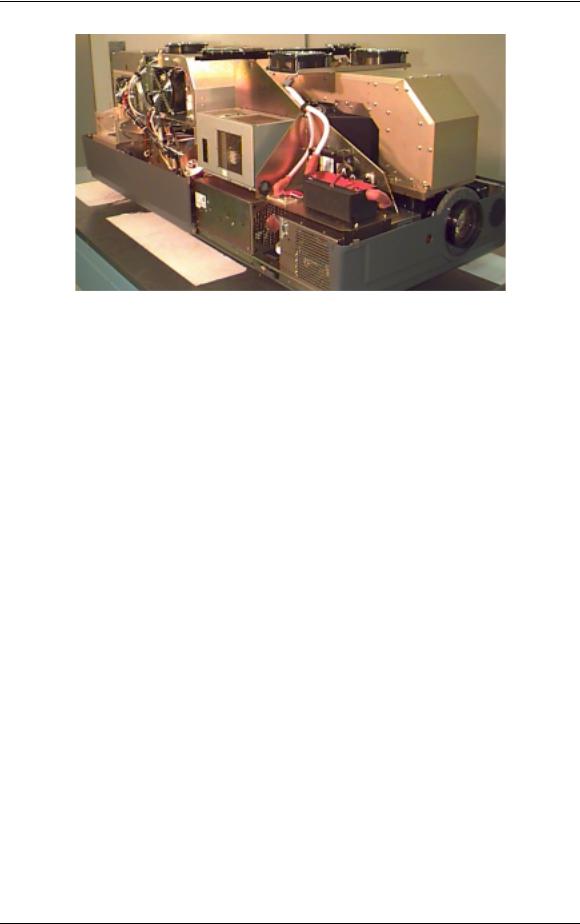
Figure 2-1 Overview of the Model 250 projector showing major components
2.2Electrical Section
The electrical section consists of the Incoming Power Circuit, and the Power Supplies and the Igniter Assembly. The following paragraphs give a list of major components and a brief description of those components. For a more detailed description of a component, refer to the chapter and section dedicated to that particular component.
Incoming Power Circuit
!Power Cord - The AC power comes in through the Power Cord to the AC Circuit Breaker.
!AC Circuit Breaker - The Circuit Breaker connects and disconnects the projector from electrical energy and protects the projector from overvoltage conditions.
!AC Line Filter - The AC SF Series Line Filter reduces radiation generated by a regulated power supply from returning to the AC power source.
Power Supplies
!Low Voltage Power Supply (LVPS) - The LVPS supplies standby voltages and the main system voltages to the projector.
!Arc Lamp Power Supply (ALPS) - The ALPS supplies power to the Igniter Assembly while the Arc Lamp is lighting. After the Arc Lamp has lit, ALPS provides the steady state power to the Arc Lamp. The ALPS also monitors the condition of the Arc Lamp and sends a feedback signal to the System Controller PCB if there is a problem.
!High Voltage Power Supply (HVPS) - The HVPS provides the Anode, Focus (G3), Black Level (G2), Blanking (G1), and Dynamic Focus voltages for the CRT.
2-2 |
Model 250 Service Manual |

Chapter 2---System Description
Igniter Assembly
The Igniter Assembly provides the high voltage pulse that lights the Arc Lamp and acts as a link from the Arc Lamp Power Supply to the Arc Lamp after the Arc Lamp has been lit.
!Igniter - The Igniter actually performs three functions. It is a step-up transformer that supplies the high voltage pulse to light the Arc Lamp. It also supplies the spark gap for the high voltage pulse. Once the Arc Lamp is lit, the Igniter acts as a link between the Arc Lamp Power Supply and the Arc Lamp for steady state operation.
!Laser Power Supply - The Laser Power Supply provides the voltage for the spark gap. The spark gap produces a high voltage pulse in the Igniter that lights the Arc Lamp.
2.3Optical Section
The optical section of the Model 250 consists of the Arc Lamp Module, the Optical Path, the ILA® , the CRTs, the Relay Lenses and the Projection Lens.
Arc Lamp Module
The Arc Lamp Module supplies high intensity light for the Model 250. Its output is rated at 2 kW. The Arc Lamp has an expected 50% lifetime (half of initial light output) of 1000 hours.
Optical Path
The Optical Path consists of all the optical components that transmit, filter, separate, bend, or straighten the Arc Lamp light. The Optical Path also includes Polarizing Prisms, Prepolarizing Prisms, Steering Prisms and the 4P Combining Prism that control the image path inside the Prism Assembly.
!Cold Mirrors (3) - The Cold Mirrors remove infrared light rays, which contain most of the heat, from the white light coming from the Arc Lamp. There are three Cold Mirrors, the first one is located in front of the Arc Lamp, and the other two are located after the Light Pipe.

 CAUTION! The term "cold mirror" is used because the mirror passes infrared light and its reflection contains only "cold' light that does not transmit appreciable heat. As a result of the absorption of infrared heat radiation, "cold" mirrors get very hot.
!Light Pipe - The Light Pipe acts as an Integrator to spread out the beam of light creating a uniform distribution of light across the face of the ILA® . This will result in a more uniform image on the screen
Model 250 Service Manual |
2-3 |
Chapter 2---System Description
!Condensing Lenses (2) - The Primary Condensing Lens collects all the light from the Light Pipe and begins to bend the light rays into a straight path. The Secondary Condensing Lens works with the Primary Condensing Lens to collimate or “straighten” the light path before it enters the Dichroic Beamsplitter Assembly.
!UV Filter - The UV Filter removes much of the unwanted ultravioltet light from the white light of the Arc Lamp.
!Dichroic Beamsplitter Assembly w/ Steering Mirrors - The Dichroic Mirrors separate white light into Red, Green, and Blue component colors. The Steering Mirrors direct the separated light beams into the Prism Assembly.
!Prism Assembly - The Prism Assembly is a large tank filled with optical fluid. It houses the following optical components:
"Pre-polarizing Beamsplitter - The Pre-polarizing Beamsplitter performs the first part of the polarizing process.
"Polarizing Beamsplitter - The Polarizing Beamsplitter performs the final function of the polarizing process.
"Steering Prisms - When the polarized light leaves the Prism Assembly and enters the ILA® , the light is modulated by the ILA® . The modulated light reflects off the ILA® mirror and returns to the Prism Assembly. Inside the Prism Assembly, the light for the red and blue reflect off the two Steering Mirrors (one for red, one for blue) and enter the 4P Combining Optic.
"4P Combining Optic - The 4P Combining Optic takes the three colored image lights from the ILA® s and combines them so they leave the Prism Assembly as a single beam of image light. That image light continues on to the Projection Lens
ILA® s - Image Light Amplifier (3)
The ILA® is a very important component in the Hughes-JVC projectors. The ILA® modulates the polarized light from the Arc Lamp. The image light from the CRT that strikes the input side of the ILA® interacts with the Liquid Crystal layer of the ILA® to impose an image on the polarized light from the Arc Lamp. The Model 250 Projector uses the Super Contrast ILA® . The Super Contrast ILA® has a sequential contrast ratio of 600:1 @ center screen.
CRTs (3)
There are three Cathode Ray Tubes (CRTs), one for each color. The CRT generates the image light that strikes the input of the ILA® . CRTs are covered in the Electronics Section.
2-4 |
Model 250 Service Manual |

Chapter 2---System Description
Relay Lens Assemblies (3)
There are three Relay Lenses, one for each color. The Relay Lens focuses the image light from the CRT onto the photosensitive layer on the input side of the ILA® . The Relay Lens is physically connected to the CRT (see Figure 2-2).
Front Projection Lens
The Model 250 comes with a choice of four standard lenses. These include a motorized Zoom Lens or one of three Fixed Lenses. All Projection Lenses have motorized focus.
!Motorized Zoom 2:1-4:1
!Fixed Lens
"0.96
"1.5:1
"5.6:1
2.4Electronic Section
The electronics section consists of the Input Cards (VICs), the Printed Circuit Boards (PCBs), and the CRT/Yoke assemblies.
Input Cards (VICs)
There are two standard Input Cards and four optional VICs. The Input Cards are the first stop for the source input signal. They provide the RGB and Sync interface for the projector. All VICs are IIC controlled.
Standard VICs:
!Standard RGBHV VIC - The RGBHV VIC is a straight feed-through with an IIC selection control.
!Graphic Enhancer Plus VIC - The Graphics Enhancer Plus VIC is exactly the same as the RGBHV VIC except for a Menu controlled adjustment for black on white graphics and text display
Optional VICs:
!YPbPr VIC - Composite Video Decoding for YPbPr
!Quad Standard Decoder VIC - Composite Video Decoding (NTSC, SECAM, and PAL)
!Quad Standard Decoder and Line Doubler VIC - Composite Video Decoding (NTSC, SECAM, and PAL) with Line Doubling
!Four-Input RGBHV - FourInput RGBHV with IIC controlled Mux (switcher)
Model 250 Service Manual |
2-5 |

Chapter 2---System Description
Printed Circuit Boards (PCB)
The Model 250 Projector has eight main PCBs:
!System Controller PCB - System Controller PCB controls much of the electronics system. It uses digital and analog circuitry to generate Menu and internal pattern overlays, and directs convergence correction and shading information. It controls the IIC data bus that sends geometric correction and VIC selection data. The System Controller PCB controls and monitors the status of power supply operations during and after the projector is powered ON.
!Raster Timing Generator PCB - The Raster Timing Generator PCB generates an internal sync for the PLL (Phase Lock Loop) circuitry. It provides sync detection and selection. It also generates the blanking pulse, provides horizontal and vertical phase adjustments, and Interlace detection.
!Video Processor PCB - The Video Processor PCB receives external image and sync signals and sends horizontal sync, vertical sync, and green sync signals to the Raster Timing Generator PCB. It adds Contrast, Brightness, Sensitivity and Threshold adjustments to the image signals and sends the image signals, G2 control lines, and G1 bias to the Video Amplifier PCB.
!Horizontal Vertical Deflection PCB - The Horizontal Vertical Deflection PCB supplies the deflection waveforms that drive the deflection yokes on the CRTs for the horizontal and vertical raster. It integrates the geometry correction such as pincushion, keystone, and vertical linearity onto the horizontal deflection waveform and adjusts the horizontal and vertical center raster.
!Convergence Deflection PCB - The Convergence Deflection PCB generates the horizontal and vertical convergence correction waveforms. It generates the horizontal and vertical Dynamic Focus Parabola used by the
High Voltage Power Supply. The Convergence Deflection PCB also provides the ILA® bias and sensitivity.
!Scan Reversal PCB - the Scan Reversal PCB reverses the deflection waveforms for both the horizontal and vertical axes for floor/ceiling mounting and front/rear mounting. It also provides scan failure detection to protect the CRT.
!Video Amplifier PCB - The Video Amplifier PCB amplifies the video signals and drives the cathodes for all three CRTs. It senses the cathode beam current and regulates the G1 and G2 for all the CRTs. The Video Amplifier PCB also provides phosphor protection for all three CRTs and CRT interface for the Focus, Heater Voltage, and Arc ground.
!Backplane - The Backplane sits in the back of the Electronics Module. The System Controller PCB, Raster Timing Generator PCB, Video Processor PCB and the VICs plug into directly the Backplane PCB. It
2-6 |
Model 250 Service Manual |

Chapter 2---System Description
provides an interconnection interface for all the electronic components in the projector.
CRT/Yoke Assemblies
The CRT/Yoke Assemblies bridge between the Optical and the Electronic sections. The CRTs could be included in the Optical section because they produces the image light transmitted to the ILA® s, but they are included in the Electronic section because they are the end user for the image signals from the VICs, Video Processor PCB, and Video Amplifier PCB. The CRTs also use the Anode, Focus, G1, and G2 voltages from the High Voltage Power Supply. The Yoke Assemblies contains the deflection and convergence coils. The deflection coils are the end-user for the horizontal and vertical deflection waveforms from the Horizontal Vertical Deflection PCB. The convergence coils use the convergence data from the Convergence Deflection PCB.
2.5Miscellaneous Items
The Miscellaneous Items section consists of components that indirectly support the main function of the projector.
Projector Covers
All Series 200 projectors including the Model 250 have a front and rear cover. Both covers can be tilted up and/or removed to service the projector. The covers should not be opened while the projector is operating without proper safety protection (review the Safety Chapter).
IR Detectors
The Model 250 can be controlled by a handheld IR Remote Control. The IR (Infrared) Detectors receive infrared pulses from these remote controls and use them to control various functions of the projector. One IR Detector is mounted on the front of the projector, the other is mounted on the System Controller PCB at the rear of the projector. IR Detectors can receive commands from the remote control from a range of about 45-ft. line of sight.
Cooling Fans
The Model 250 has eleven cooling fans of various sizes plus a large blower for the Arc Lamp. The cooling fans maintain thermal stability for the projector. The Arc Lamp especially depends on the cooling fans. If the fans are not operating while the Arc Lamp is on, the Lamp will implode from overheating. Many of the Printed Circuit Boards generate a lot of heat and require airflow from the cooling fans. The fans provide cooling to the PCBs and CRTs to maintain for stable operation.
Air Filters
The Model 250 has three air filters (see Figure 2-2). The Air Filters filter the incoming air to minimize the amount of dust and air-borne particles inside the
Model 250 Service Manual |
2-7 |

Chapter 2---System Description
projector. These air-borne particles can land on optics such as the ILA® and cause large diffuse dark areas on the screen.
EMI Shield
The Model 250 has an EMI (Electro-Magnetic Interference) Shield that traps and collects high frequency noise that is radiated by switching power supplies such as the Arc Lamp Power Supply and the Low Voltage Power Supply. This high frequency noise can interfere with the operation of radios, televisions, and other electronic devices.
Figure 2-2 Relative location of CRTs, Relay Lenses, ILA® s, and Air Filters.
2-8 |
Model 250 Service Manual |

Chapter 2---System Description
Model 250 Service Manual |
2-9 |
Chapter 3---Electrical
3.0 Electrical
Contents
3.1 |
Safety............................................................................................................ |
3-1 |
3.2 |
Incoming Power Circuit ............................................................................... |
3-2 |
|
AC Power Cord .......................................................................................... |
3-2 |
|
AC Circuit Breaker..................................................................................... |
3-2 |
|
AC EMI Filter ............................................................................................ |
3-2 |
3.3 |
Power Supplies............................................................................................. |
3-3 |
|
Low Voltage Power Supply ....................................................................... |
3-3 |
|
Arc Lamp Power Supply ............................................................................ |
3-5 |
|
High Voltage Power Supply....................................................................... |
3-9 |
3.4 |
Igniter Assembly .......................................................................................... |
3-15 |
|
|
|
|
|
|
3.1 Safety

 CAUTION! Before performing procedures in this chapter, review the chapter on Safety at the beginning of this manual.
 WARNING!!! When performing procedures in this chapter that require projector covers to be off, wear high voltage gloves
(ANSI/ASTM 10,000 volt rated) when working near the CRTs, Arc Lamp, or power supplies. Wear safety goggles (rated X5) when working anywhere near the light path from the arc lamp or the projection lens.

 CAUTION! It is very strongly recommended that setup data be downloaded (Exported, see section 8.2 Importing/Exporting) before performing any of the following procedures. Exporting baseline source setup data to disk is an excellent precautionary measure. It will save the time of setting up new source file(s) in the case of an unexpected problem.
Model 250 Service Manual |
3-1 |

Chapter 3---Electrical
Left/Right Orientation: When referring to the left or right in this chapter, it is with reference to standing at the rear of the projector, facing the screen.
Connectors on subassemblies and PCBs have tabs that must be released first before pulling on the connector. The proper procedure is to push slightly IN on the connector, then squeeze the tab, then pull the connector out.
3.2. Incoming Power Circuit
AC Power Cord
The Power Cord performs one basic function: to deliver the AC power from the power source to the projector. It must be configured to meet the Electrical Specifications for the region the projector will be used. The Power Cord type is NEMA 5-20, 20A, 250A.
AC Circuit Breaker
The AC Circuit Breaker has two basic functions: one is to connect and disconnect electrical power from the projector, the second is to protect the projector from over-voltage conditions.
When the AC Circuit Breaker is in the OFF position, no electrical energy will reach any part of the projector except for the AC Circuit Breaker. When the AC Circuit Breaker is in the ON position, electrical energy goes to the AC Line Filter and on to the Low Voltage Power Supply and Arc Lamp Power Supply. When the AC Circuit Breaker is in the ON position but the projector has not received the POWER ON command either from an IR Remote Control or from a PC or Laptop computer, the projector is in Standby mode. In the Standby mode, the +5.1 V Standby and the +24 V Standby Voltages maintain power to the CPU chips on the System Controller PCB, the IR Detectors, and to the cooling fans.
The AC Circuit Breaker is rated at 90-264 Vac (RMS), 50/60 Hz. The current rating is 13 Amps RMS at 90 Vac.
The power requirements of the Model 250 Projector are 200-264 Vac, 50/60 Hz, single phase. The power consumption is rated at 2800-Watts maximum.
AC EMI Filter
The AC EMI (Electro-Magnetic Interference) Filter prevents switching noise from a regulated power supply such as the Low Voltage Power Supply and the Arc Lamp Power Supply, from returning to the AC power source. This switching noise interferes with the operation of radios, televisions, and other electronic appliances
3-2 |
Model 250 Service Manual |

Chapter 3---Electrical
3.3 Power Supplies
All Series 200 projectors including the Model 250 have three power supplies. These include:
!Low Voltage Power Supply
!Arc Lamp Power Supply
!High Voltage Power Supply
There is a fourth power supply, the Laser Power Supply, but that power supply is used only for the Igniter Assembly during Arc Lamp lighting.
Low Voltage Power Supply (LVPS)
LVPS - Main Functions:
!Provides all the low voltages needed by the projector.
!Provides standby power (+5.1V) when the projector is OFF but the AC Circuit Breaker is in the ON position.
!Provides power (+24 V) for all cooling fans.
LVPS - Inputs:
The Low Voltage Power Supply receives AC input power directly from the AC Line Filter. The input range is from 220 VAC to 240 VAC, at 50/60 Hz.
/LV_ENA - from the System Controller PCB. This signal enables the LVPS when the System Controller receives a Power On command.
/FAN_ENA - from the System Controller PCB. This signal enables the +24v standby voltage for the projector fans.
/COVER_ON - signal enables the non-standby outputs.
/ = Active low
LVPS - Outputs:
!+ 5.1VDC Main
!+ 5.1VDC Stdby
!+ 6.2VDC
!± 15VDC
!+ 24VDC
!+ 80VDC
/LV_OK - this diagnostic signal tells the System Controller PCB the status of the non-standby supply (all the outputs are working or not working).
Model 250 Service Manual |
3-3 |
Chapter 3---Electrical
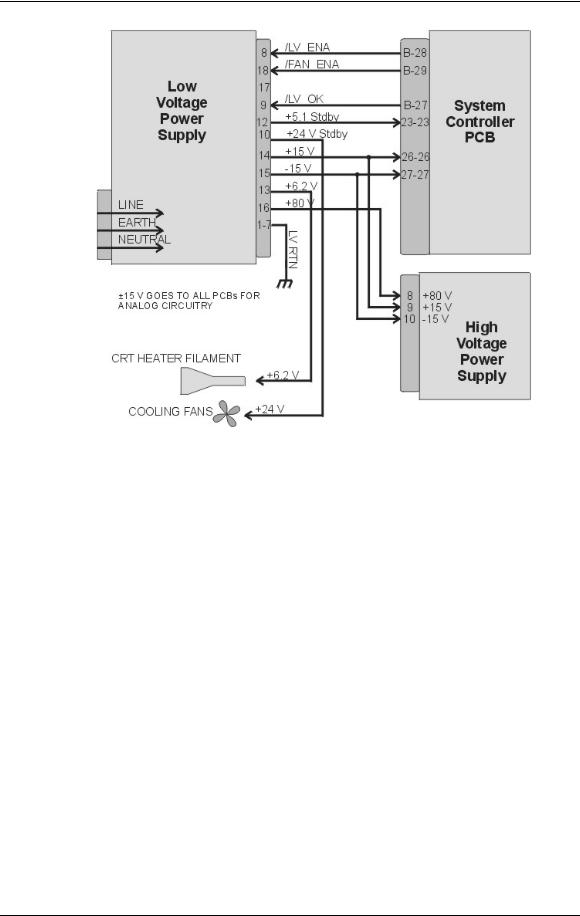
Figure 3-1 Low Voltage Power Supply I/O Diagram.
LVPS - Operation:
AC power is delivered to the Low Voltage Power Supply from the AC line filter. The AC is rectified to a DC Voltage, filtered, and goes through a power factor correction circuit to force the current waveform to follow the voltage waveform.
The +5.1V Standby is on whenever AC power is connected to the projector and the circuit breaker on the rear panel is in the ON position. When the AC Circuit Breaker is in the ON position, the LVPS supplies the +5.1 V to the System Controller PCB. The System Controller PCB drives the /FAN_ENA signal to the LVPS to turn on the +24V Standby power for the cooling fans. If the System Controller PCB does not receive a POWER ON command from an IR remote control or a PC, it waits about 10 minutes and then tells the LVPS (/FAN_ENA goes high) to shut off +24V Standby power. This shuts off the cooling fans. More importantly, after the System Controller PCB receives a POWER OFF command it waits 10 minutes, and then tells the LVPS to shut off the cooling fans. This gives the Arc Lamp and the PCBs time to cool down to avoid damage or reduction of operating life.
When the projector receives a POWER ON command from an IR Remote Control or PC, the System Controller PCB sends the /LV_ENA signal to the LVPS. The Low Voltage Power Supply needs to receive the /LV_ENA from the System Controller PCB and the /COVER_ON signal to activate all the non-standby voltages. These include:
3-4 |
Model 250 Service Manual |
Chapter 3---Electrical
!+5.1V for digital components
!+6.2V for CRT filaments
!±15V for analog circuits
!+80V supply used by the High Voltage Power Supply, Video Amplifier PCB, and the Horizontal/Vertical Deflection PCB.
LVPS - Service Adjustments
There are no service adjustments for the Low Voltage Power Supply.
LVPS - Remove and Replace
Tools Needed:
#2 Posi-drive Phillips-head screwdriver Parts Needed:
Low Voltage Power Supply - p/n 102520
To remove the Low Voltage Power Supply:
1.Power off the projector by IR Remote or PC, and allow the cooling fans to run until they shut off.
2.Turn the AC Circuit Breaker to the OFF position and unplug the AC Power Cord.
3.Remove the front cover (see Projector Covers section 6.1).
4.Remove the lower-right-side panel by removing the 5 Pozi-drive screws securing it.
5.Remove the 5 Pozi-drive screws securing the EMI Shield. Slide the shield to the left and remove it.
6.Remove J76 (DC Output) and J75 (AC Input) from the left side of the Low Voltage Power Supply.
NOTE: These connectors may be a little difficult to remove and it may be necessary to pull the LVPS partly out of the chassis in order to get a better grip on the connectors.
7.Carefully slide the Low Voltage Power Supply out of the projector.
8.Reinstall the LVPS in reverse order. After installing a new LVPS, it may be necessary to touch-up the Timing, Geometry, Electronic Focus, ILA® Bias/Sensitivity, Convergence, G2, and Shading.
Arc Lamp Power Supply (ALPS)
ALPS - Main Functions:
!Provides ignition power to turn the Arc Lamp ON (via the Igniter).
!Provides steady state power to maintain the Arc Lamp operation.
Model 250 Service Manual |
3-5 |

Chapter 3---Electrical
ALPS - Inputs:
AC input power: Directly from the AC Line Filter. The input range is from 220240 VAC, at 50/60 Hz.
/LAMP_ENA - from the System Controller PCB. Turns on the ALPS.
/COVER_ON - signal enabling the Arc Lamp Power Supply.
/LAMP_OK - the input is jumpered at the Arc Lamp Power Supply (tied to ground) so it is always low.
/ = Active Low
ALPS - Outputs:
!+170 VDC output during the boost phase to get Arc Lamp ignition. This supplies the power for the Igniter.
!Run Voltage - 25 to 31 V to maintain the arc lamp operation.
!Current - 70 to 85 amps to maintain the arc lamp operation.
!LAMP_OUT - Lamp output voltage, positive.
!LAMP_RTN - Lamp return.
!/LAMP_LIT - signal to System Controller PCB indicating that the Arc Lamp is lit.
!/LAMP_OK - signal to System Controller PCB (no real indication).
3-6 |
Model 250 Service Manual |
Chapter 3---Electrical
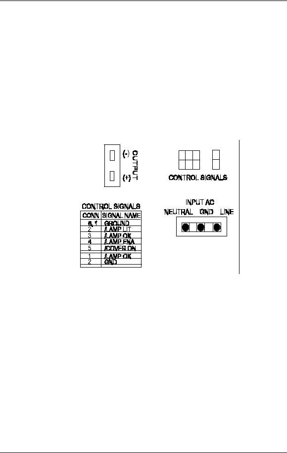
Figure 3-2 Arc Lamp Power Supply signals and voltages.
ALPS - Operation:
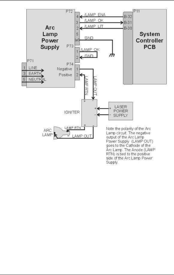
Three signals (/LAMP_ENA, /COVER_ON, and /LAMP_OK) are required in order for the Arc Lamp Power Supply to light the Arc Lamp. The /LAMP_OK (active low) input is jumpered to ground at the Arc Lamp Power Supply, so it is always low. The Arc Lamp Power Supply sends the /LAMP_OK to the System Controller PCB. The System Controller PCB then sends the /LAMP_ENA signal back to the Arc Lamp Power Supply and activates the Arc Lamp Power Supply.
Once the Arc Lamp Power Supply receives the /LAMP_ENA signal from the System Controller PCB, it supplies the +170 VDC boost voltage to the primary coil of the Igniter. The Laser Power Supply charges up a capacitor. When the capacitor reaches +5.5 kV, a spark gap arcs causing a very high voltage pulse (approximately 32 kV) to be induced onto the secondary coil inside the Igniter. This high voltage pulse ignites the Xenon Arc Lamp. Immediately after the Arc Lamp lights, the voltage from the Arc Lamp Power Supply drops to about 25-31 volts at 70-85 amps. It will stay at this level during normal Arc Lamp operation.
Model 250 Service Manual |
3-7 |
Chapter 3---Electrical
The Arc Lamp Power Supply sends the
/LAMP_LIT signal back to the System Controller when the Arc Lamp is lit.
The Arc Lamp regulates its output to give a constant Arc Lamp power. If the Arc Lamp has not lit within 20 seconds (/LAMP_LIT still high), the System Controller PCB will try once more to re-initiate the sequence. If the Arc Lamp still fails to light, an error code will appear on the back panel (see section 7.22
Error Codes).
The Arc Lamp Power Supply negative output goes to the Cathode of the Arc Lamp. The positive output goes to the Anode of the Arc Lamp and is tied to chassis ground.
The Arc Lamp Power Supply is shielded electrically and magnetically to prevent noise or disturbances in the CRTs or other circuitry.
Figure 3-3 Arc Lamp Power Supply connections.
ALPS - Service Adjustments
The Arc Lamp Power Supply for the Model 250 is preset at the factory and does not have any Service Adjustments. The output is programmed for a constant
2 kW. Arc Lamp replacement does not require any electrical readjustments.
ALPS - Remove and Replace
Tools Needed
#2 Pozi-drive Phillips-head screwdriver
Parts Needed
Arc Lamp Power Supply p/n - 105216
To remove the Arc Lamp Power Supply (ALPS):
1.Power off the projector by IR Remote or PC, and allow the cooling fans to run until they shut off.
3-8 |
Model 250 Service Manual |

Chapter 3---Electrical
2.Turn the AC Circuit Breaker to the OFF position and unplug the AC Power Cord.
3.Remove the front cover (see section 6.1 Projector Covers ).
4.Remove the lower-right-side panel by removing the five Pozi-drive screws securing it.
5.Remove the five Pozi-drive screws securing the EMI Shield. Slide the shield to the left and remove it.
6.Disconnect the INPUT AC plug.
7.Disconnect the two CONTROL SIGNALS cables. The /LAMP_OK signal jumper is attached to the CONTROL SIGNAL cable by a cable tie. Do not cut this cable tie.
8.Disconnect the Arc Lamp Power Supply OUTPUT cables from the (+) and (-) terminals. Take care not to damage the 470µf capacitor across the output cables. The (+) cable has a red shrink tubing on it; the (-) has a black shrink tubing on it.
NOTE: The capacitor on the output of the Arc Lamp Power Supply filters transient spikes from the Arc Lamp when it arcs. Re-attach the capacitor with the Arc Lamp output leads during reinstallation of new Arc Lamp Power Supply.
9.Remove the 1 Pozi-drive Phillips-head screws from the bottom of the front of the Arc Lamp Power Supply. The other screw was removed with the EMI Shield.
10.Carefully slide the Arc Lamp Power Supply out of the projector.
11.Replace the Arc Lamp Power Supply in the reverse order.
High Voltage Power Supply (HVPS)
HVPS - Main Functions
The High Voltage Power Supply provides the following functions:
!Phase locked loop circuit for synchronization of the High Voltage Power Supply to the HVPS_SYNC
!Generation of Anode voltages (25 kV) for all three CRTs (RGB)
!Generation of Focus voltage (G3) (7 kV) for all three CRTs (RGB)
!Generation of G2 (1200 V) supply voltage for the Video Amplifier PCB.
!Generation of G1 (-150 V) supply voltage for the Video Amplifier PCB.
!Dynamic Focus Amplifier using horizontal and vertical parabolas supplied to the High Voltage Power Supply.
!External CRT Protection and generation of /HV_OK signal
Model 250 Service Manual |
3-9 |
Chapter 3---Electrical
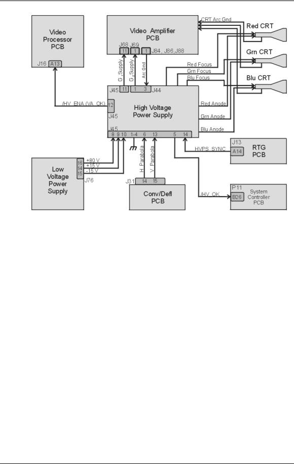
Figure 3-4 High Voltage Power Supply I/O signals.
HVPS - Inputs
HVPS_SYNC - this signal is generated on the Raster Timing Generator PCB. Square wave HCT level with 50 or 33% duty cycle. The signal is synchronized to horizontal sync.
/HV_ENA - The HVPS shutdown signal from the Video Amplifier PCB (/VA_OK).
H_PARABOLA - The horizontal parabola from the Convergence Deflection PCB used by the Dynamic Focus Amplifier.
V_PARABOLA - The vertical parabola from the Convergence Deflection PCB used by the Dynamic Focus Amplifier.
± 15 V. - The power source for the analog circuitry in the High Voltage Power Supply.
+ 80 V. - The input power for the High Voltage section of the High Voltage Power Supply.
HVPS - Outputs
G1 Supply - goes to Video Amplifier PCB
G2 Supply - goes to Video Amplifier PCB
/HV_OK - goes to System Controller PCB
3-10 |
Model 250 Service Manual |

Chapter 3---Electrical
RGB Anode Voltage - goes directly to each CRT
RGB Focus Voltage - goes directly to each CRT
Arc Ground - The Arc Ground protection for each CRT from the Video Amplifier PCB.
HVPS - Operation
The High Voltage Power Supply has three basic functions.
!High Voltage Generation
!Focus Voltages
!High Voltage and CRT Protection
High Voltage Generation - The High Voltage Amplifier section converts the +80 V from the Low Voltage Power Supply, to 25 kV, and divides it into three outputs for each CRT. It also uses the HVPS_SYNC signal from the Raster Timing Generator PCB. This signal is synchronized to the horizontal sync to eliminate one source of moving noise on the screen. The High Voltage section also supplies the G2 Voltage for the Video Amplifier PCB.
Focus Voltages - The High Voltage Power Supply receives the horizontal and vertical parabolas from the Convergence Deflection PCB and adds them together. They are amplified and sent to the Focus Pack section. The Focus Pack section couples the amplified parabola waveforms to the Focus Voltages. The Focus Pack divides the Focus Voltage into three signals and outputs each signal to a CRT. The DC Focus Voltages are manually adjusted as necessary.
The Arc Ground signal goes to the Video Amplifier PCB and from there, connects to the CRT. It provides a direct return path for arc currents in the event of internal CRT arcing.
High Voltage and CRT Protection - The High Voltage Power Supply receives a /HV_ENA (/VA_OK) signal from the Video Amplifier PCB. This signal goes to the Protect OR section. The Protect OR section also checks the incoming +80 V. from the LVPS for an overcurrent condition. The Protect OR section also monitors the high voltage output for an overvoltage condition. If any of these checks shows a problem the Protect OR section shuts down the high voltage amplifier. The Protect OR section outputs the /HV_OK signal telling the System Controller PCB that the High Voltage Power Supply is functioning properly.
HVPS - Service Adjustments
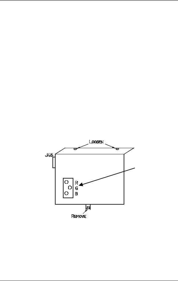
Normally, the only High Voltage Power Supply adjustments are for CRT Focus. The CRT Focus Voltage adjusts are mechanical potentiometers located on the side of the High Voltage Power Supply (see Figure 3-5) that adjust the focus for each CRT. The CRT Focus Voltage adjustments are detailed in the CRT Section (see section 5.10 CRT/Yoke Assemblies).
Model 250 Service Manual |
3-11 |
Chapter 3---Electrical
HVPS - Remove and Replace
Tools Needed
#1 Pozi-drive Phillips-head screwdriver #2 Pozi-drive Phillips-head screwdriver small Flathead screwdriver
Parts Needed
High Voltage Power Supply p/n 102566
To remove the High Voltage Power Supply:
1.Power off the projector by IR Remote or PC, and allow the cooling fans to run until they shut off.
2.Turn the AC Circuit Breaker to the OFF position and unplug the AC Power Cord.
3.Remove the front cover.
4.Remove the High Voltage Power Supply cover (see Figure 3-5) by removing the 1 Pozi-drive screw that secures the HVPS at the bottom of the cover and loosening the 2 Pozi-drive screws at the top of the front flap.
Electronic
Focus
Adjustment
Figure 3-5 High Voltage Power Supply cover.
3-12 |
Model 250 Service Manual |
|
|
|
|
Chapter 3---Electrical |
|
Table 3-1 HVPS - P45 I/O Pinout |
|
||
|
PIN # |
Description |
PIN # |
Description |
|
1 |
GND (+80V) |
9 |
+15V |
|
|
|
|
|
|
2 |
GND (+15V) |
10 |
-15V |
|
|
|
|
|
|
3 |
GND (-15V) |
11 |
G1 SUPPLY |
|
|
|
|
|
|
4 |
GND (G1) |
12 |
/HV_ENA |
|
|
|
|
|
|
5 |
/HV_OK |
13 |
V PARABOLA |
|
|
|
|
|
|
6 |
H PARABOLA |
14 |
H DRIVE (HVPS_SYNC |
|
|
|
|
|
|
7 |
GND (DAF) |
|
|
|
|
|
|
|
|
8 |
+80V |
|
|
|
|
|
|
|
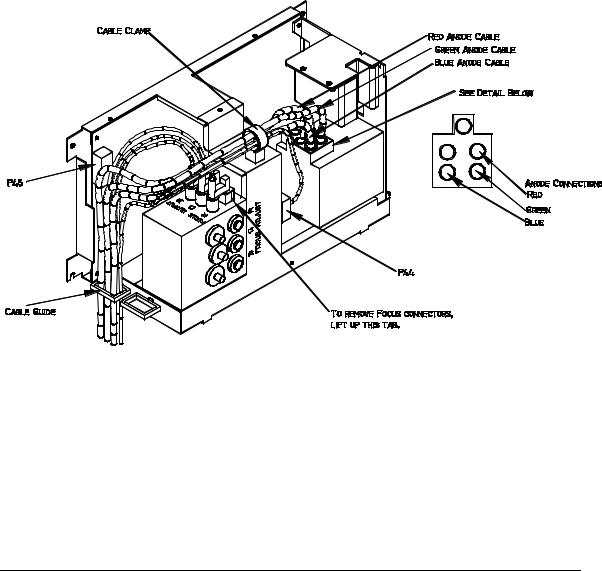
Figure 3-6 High Voltage Power Supply.
5.Carefully slide the cover upward and outward to remove it.
NOTE: Refer to Figure 4-5 for the remainder of this procedure.
6.Disconnect the three CRT Anode Cables.
7.Disconnect P44-G2 Out (at the middle-front of the HVPS).
8.Unsnap the cable clamp at the top of the HVPS.
9.Remove the Anode Cables and the P44 cable from the cable clamp.
Model 250 Service Manual |
3-13 |

Chapter 3---Electrical
10.Disconnect P45 (“Control”) at upper left of HVPS.
11.Disconnect and label the three Focus cables. The square tabs on these cables (see Figure 3-6) may have to be lifted up. Gently pry up with a small Flathead screwdriver.
12.Remove all the cables from the slot in the cable guide located on the left side of the HVPS.
13.Verify that all plugs and cables are removed and out of the way so the HVPS is free to be removed.
14.Loosen (do not remove) the two Posi-drive screws (at the bottom of the HVPS) that secure the HVPS metal housing to the projector.
15.Remove the two Posi-drive screws that hold the top of the HVPS metal housing to the projector frame.
16.Grasp the HVPS at the bottom and lift upward and outward so that it slides away from the bottom screws.
17.Reinstall the High Voltage Power Supply in the reverse order.
NOTE: When reinstalling the High Voltage Power Supply:
!Make sure it slides over the bottom screws and the lip at the top of the projector frame.
!Make sure each anode cable “snaps” back into its receptacle. The receptacles are about 2” inside the hole where the cable goes.
!Make sure the rear flap on each focus cable connector snaps over the square socket securely. Wiggle the connector a little to make it fits securely.
18.Replace the HVPS cover.
19.Replace the projector covers.
20.After replacing the HVPS, check and adjust Electronic Focus as necessary.
3-14 |
Model 250 Service Manual |
 Loading...