

Page 1
SERVICE
MANUAL
Model 250 Projector
2310 Camino Vida Roble
Carlsbad, California 92009
Phone: (760) 929-5300
Fax: (760) 929-5410
Page 2

DECLARATION OF CONFORMITY
PER ISO/IEC GUIDE 22 AND EN 45014
Manufacturer
Hughes-JVC declares that this product conforms to the following Product
Specifications (Directive/Standard):
Safety:EN 60950
EMC: EN 55022 (1988) / CISPR-22 (1986) Class "A"
In addition, the above product complies with the requirements of the Low Voltage
Directive 73/23 EEC and the EMC Directive 89/336/EEC.
106784 First Edition May 1999
:
Hughes JVC
2310 Camino Vida Roble
Carlsbad, Ca 92009
USA
IEC 950 (1992)
EN 50082-1 (1992) / IEC 801-2(1991)
EN 50082-1 (1992) / IEC 801-3(1984)
EN 50082-1 (1992) / IEC 801-4(1988)
ANSI C63.4-1992, FCC, Part 15, Class A
© Copyright 1999 by Hughes-JVC Technology Corporation.
All worldwide rights reserved.
This manual was produced by Hughes-JVC Technology Corporation and may be revised
without prior notice.
No part of this manual may be reproduced in any form without the express written
permission of Hughes-JVC Technology Corporation.
ILA® is a registered trademark of Hughes-JVC Technology Corporation.
ii
Model 250 Service Manual
Page 3

Table of Contents
Safety Information
....................................................................................v
Chapter 1 Introduction
1.1 Safety...................................................................................................... 1-1
1.2 Updates...................................................................................................1-2
1.3 Acronyms...............................................................................................1-2
Chapter 2 System Description
2.1 Introduction............................................................................................2-1
2.2 Electrical Section....................................................................................2-2
2.3 Optical Section.......................................................................................2-3
2.4 Electronic Section ..................................................................................2-5
2.5 Miscellaneous Items............................................................................... 2-7
Chapter 3 Electrical
3.1 Safety...................................................................................................... 3-1
3.2 Incoming Power Circuit.........................................................................3-2
3.3 Power Supplies....................................................................................... 3-3
3.4 Igniter Assembly....................................................................................-15
Chapter 4 Optical
4.1 Arc Lamp................................................................................................4-2
4.2 Optical Path............................................................................................ 4-7
4.3 ILA®.......................................................................................................4-12
4.4 Relay Lenses...........................................................................................4-19
4.5 Projection Lens....................................................................................... 4-19
Chapter 5 Electronic
5.1 Safety...................................................................................................... 5-1
5.2 Introduction............................................................................................5-2
5.3 System Controller PCB..........................................................................5-3
5.4 Video Processor PCB............................................................................. 5-11
5.5 Raster Timing Generator PCB ............................................................... 5-16
5.6 Horizontal Vertical Deflection PCB ......................................................5-21
5.7 Convergence Deflection PCB ................................................................ 5-28
5.8 Scan Reversal PCB.................................................................................5-34
5.9 Video Amplifier PCB............................................................................. 5-43
5.10 CRT/Yoke Assemblies.......................................................................... 5-51
5.11 VICs ...................................................................................................... 5-58
5.12 Backplane..............................................................................................5-74
Chapter 6 Miscellaneous Items
6.1 Projector Covers..................................................................................... 6-1
6.2 Electronics Module Tilt-up .................................................................... 6-2
6.3 Ventilation.............................................................................................. 6-3
6.4 Air Filters ............................................................................................... 6-4
Model 250 Projector Service Manual iii
Page 4

6.5 IR Detectors............................................................................................6-4
6.6 EMI Shield ............................................................................................. 6-4
6.7 Cleaning Lenses, ILA® Assemblies, and Mirrors...................................6-5
Chapter 7 Troubleshooting
7.1 Safety...................................................................................................... 7-1
7.2 LEDs.......................................................................................................7-2
7.3 Diagrams ................................................................................................ 7-12
7.4 Error Codes ............................................................................................7-22
7.5 Troubleshooting Guide........................................................................... 7-25
Chapter 8 Software and Protocol
8.1 Software Updating..................................................................................8-1
8.2 Importing/Exporting............................................................................... 8-5
8.3 Terminals and Communication Protocol................................................8-10
Chapter 9 Parts
9.1 Replacement Parts List...........................................................................9-1
9.2 Recommended Spares............................................................................9-3
Glossary
.........................................................................................................A-1
iv
Model 250 Service Manual
Page 5

1.0 Introduction
Contents
1.1 Safety............................................................................................................ 1-1
1.2 Updates.........................................................................................................1-2
1.3 Acronyms Used............................................................................................1-2
The Model 250 Service Manual will provide information on how the each of the
different components function individually and how they work together to take a
source input image and project that image onto the screen. It will provide a list of
the tools and procedures needed to perform necessary adjustments and to remove
and replace components. The tools needed to perform any task are included in the
procedure. The Model 250 Service Manual will provide diagrams and test points
to help in diagnosing and troubleshooting. It will provide illustrations to show
location and proper configuration of major and minor components. This manual
will assist the Hughes-JVC Certified Technician with information to properly
maintain and when necessary, troubleshoot the Model 250 projector. Use the
Model 250 Service Manual in conjunction with the Model 250 User’s Guide.
Chapter 1---Introduction
The User’s Guide covers
!
!
!
!
This Service Manual covers:
!
!
!
!
Together, the Service Manual and User’s Guide provide a qualified service person
with information to properly operate and maintain the projector.
1.1 Safety
This projector contains high voltages in the power supplies and around the CRTs
and high intensity light sources in and around the Arc Lamp and optical path.
Read the entire Safety Chapter at the front of this manual before performing any
adjustments or maintenance.
Installation,
Operation,
Setup Adjustments
Specifications
Projector functional description
Service adjustments
Removal and replacement of subassemblies
Troubleshooting
Model 250 Service Manual 1-1
Page 6

Chapter 1---Introduction
When performing procedures that call for the projector’s power to be on, always
wear high voltage gloves (ANSI/ASTM 10,000 volt rated) when working around
the CRTs, Arc Lamp or power supplies. Wear safety goggles (rated X5) when
working near the light path from the Arc Lamp or at all times around the
projection lens.
1.2 Updates
Hughes-JVC will periodically provide bulletins and /or manual supplements to
ensure the continued accuracy of this service manual.
1.3 Acronyms Used
ALPS Arc Lamp Power Supply
C Chrominance
CDB Convergence/Deflection Board
CH Channel
CPU Central Processing Unit
CRT Cathode Ray Tube
EMI Electromagnetic Interference
EPROM Erasable Programmable Read-Only Memory
FPGA Field Programmable Gate Array
F to V Frequency to Voltage
G1 CRT Grid 1
G2 CRT Grid 2
HVDB Horizontal/Vertical Deflection Board
Hz Hertz
HSYNC Horizontal Sync
HVDB Horizontal/Vertical Deflection Board
HVPS High Voltage Power Supply
IIC Inter-Integrated Circuit
®
ILA
I/O Input/Output
I/R I nfrared
kHz Kilohertz
LED Light Emitting Diode
LVPS Low Voltage Power Supply
NTSC National Television Standards Committee
PAL Phase Alternating Line
PCB Printed Circuit Board
PLL P hase Lock Loop
PLUGE Picture Line-Up Generating Equipment
RAM Random Access Memory
RGB Red, Green and Blue
RGBHV Red, Green, Blue, Horizontal, Vertical
ROM Read Only Memory
RTG Raster Timing Generator
SCB System Controller Board
Image Light Amplifier
1-2 Model 250 Service Manual
Page 7

Chapter 1---Introduction
SECAM Sequential couleur a memoire (sequencial
color with memory
SRB Scan Reversal Board
SYNC Synchronization
TTL Transistor-Transistor Logic
UL Underwriter Laboratories
UV Ultraviolet
VAB Video Amplifier Board
VCO Voltage Controlled Oscillator
VIC Video Input Card
VIN Video Input
VPB Video Processor Board
VSYNC Vertical Sync
VTR Video Tape Recorder
Y Luminance
Model 250 Service Manual 1-3
Page 8

2.0 System Description
Contents
2.1 Introduction.................................................................................................. 2-1
2.2 Electrical Section..........................................................................................2-2
Incoming Power Circuit............................................................................. 2-2
Power Supplies........................................................................................... 2-2
Igniter Assembly........................................................................................ 2-3
2.3 Optical Section............................................................................................. 2-3
Arc Lamp Module...................................................................................... 2-3
Optical Path................................................................................................ 2-3
ILA®s..........................................................................................................2-4
CRTs .......................................................................................................... 2-4
Relay Lenses ..............................................................................................2-5
Projection Lens...........................................................................................2-5
2.4 Electronic Section ........................................................................................2-5
VICs ........................................................................................................... 2-5
PCBs........................................................................................................... 2-6
CRT/Yoke Assemblies............................................................................... 2-7
2.5 Miscellaneous Items..................................................................................... 2-7
Projector Covers......................................................................................... 2-7
IR Detectors................................................................................................2-7
Cooling Fans .............................................................................................. 2-7
Air Filters ................................................................................................... 2-7
EMI Shield................................................................................................. 2-8
Chapter 2---System Description
2.1
Model 250 Service Manual 2-1
Introduction
This chapter is divided into four basic sections: the Electrical Section, the Optical
Section, the Electronic Section and the Miscellaneous Items. Each section gives a
basic description of the components in the section and a description of the
function of those components. This provides an overall view of the projector and
its subsystems for a general understanding of how these systems contribute to the
function of the projector.
Page 9
Chapter 2---System Description
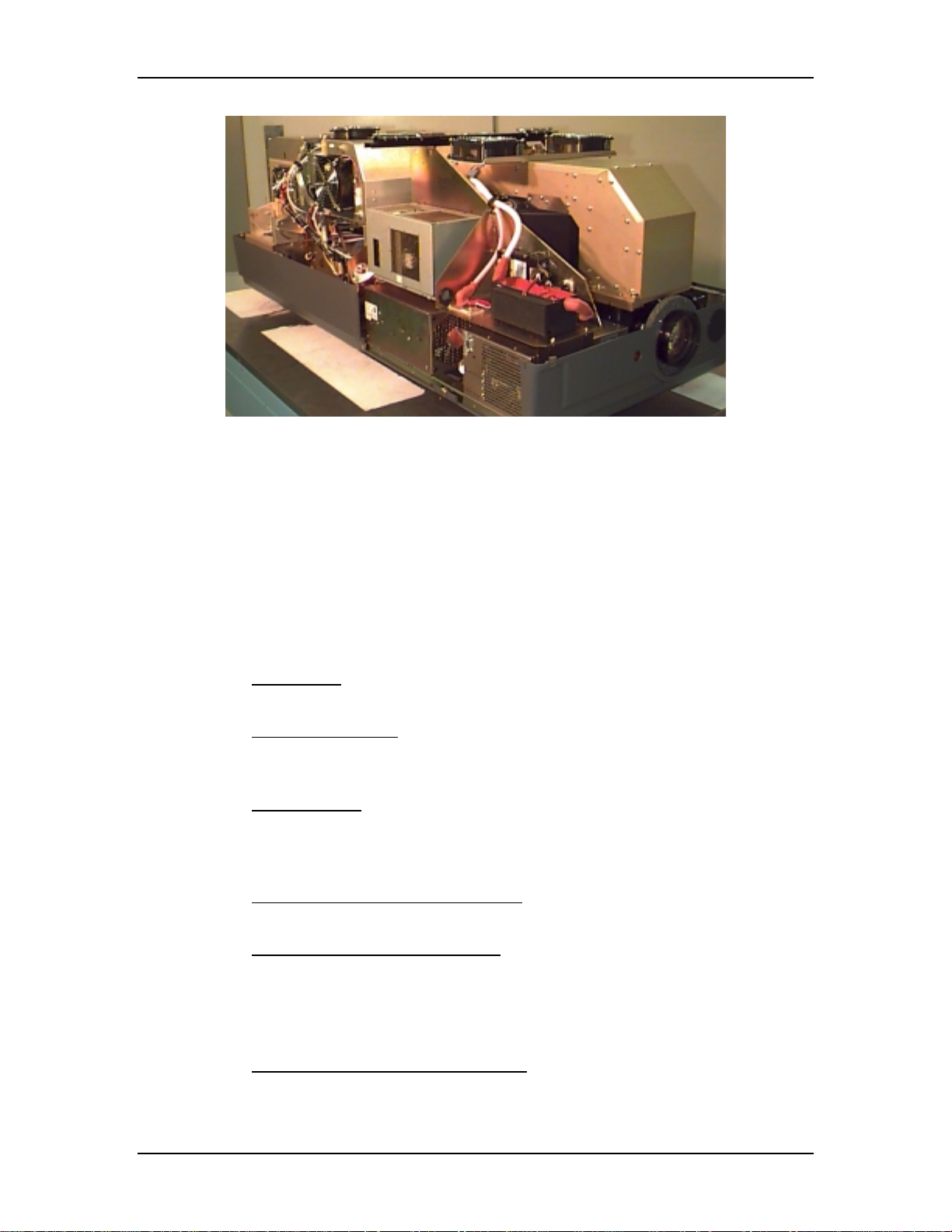
Figure 2-1
2.2
Overview of the Model 250 projector showing major components
Electrical Section
The electrical section consists of the Incoming Power Circuit, and the Power
Supplies and the Igniter Assembly. The following paragraphs give a list of major
components and a brief description of those components. For a more detailed
description of a component, refer to the chapter and section dedicated to that
particular component.
Incoming Power Circuit
!
Power Cord - The AC power comes in through the Power Cord to the AC
Circuit Breaker.
!
AC Circuit Breaker - The Circuit Breaker connects and disconnects the
projector from electrical energy and protects the projector from overvoltage conditions.
!
AC Line Filter - The AC SF Series Line Filter reduces radiation generated
by a regulated power supply from returning to the AC power source.
Power Supplies
!
Low Voltage Power Supply (LVPS) - The LVPS supplies standby
voltages and the main system voltages to the projector.
!
Arc Lamp Power Supply (ALPS) - The ALPS supplies power to the
Igniter Assembly while the Arc Lamp is lighting. After the Arc Lamp has
lit, ALPS provides the steady state power to the Arc Lamp. The ALPS
also monitors the condition of the Arc Lamp and sends a feedback signal
to the System Controller PCB if there is a problem.
!
High Voltage Power Supply (HVPS) - The HVPS provides the Anode,
Focus (G3), Black Level (G2), Blanking (G1), and Dynamic Focus voltages
for the CRT.
2-2 Model 250 Service Manual
Page 10
Chapter 2---System Description
Igniter Assembly
The Igniter Assembly provides the high voltage pulse that lights the Arc Lamp
and acts as a link from the Arc Lamp Power Supply to the Arc Lamp after the Arc
Lamp has been lit.
!
Igniter - The Igniter actually performs three functions. It is a step-up
transformer that supplies the high voltage pulse to light the Arc Lamp. It
also supplies the spark gap for the high voltage pulse. Once the Arc Lamp
is lit, the Igniter acts as a link between the Arc Lamp Power Supply and
the Arc Lamp for steady state operation.
!
Laser Power Supply - The Laser Power Supply provides the voltage for
the spark gap. The spark gap produces a high voltage pulse in the Igniter
that lights the Arc Lamp.
2.3
Optical Section
The optical section of the Model 250 consists of the Arc Lamp Module, the
Optical Path, the ILA®, the CRTs, the Relay Lenses and the Projection Lens.
Arc Lamp Module
The Arc Lamp Module supplies high intensity light for the Model 250. Its output
is rated at 2 kW. The Arc Lamp has an expected 50% lifetime (half of initial light
output) of 1000 hours.
Optical Path
The Optical Path consists of all the optical components that transmit, filter,
separate, bend, or straighten the Arc Lamp light. The Optical Path also includes
Polarizing Prisms, Prepolarizing Prisms, Steering Prisms and the 4P Combining
Prism that control the image path inside the Prism Assembly.
!
Cold Mirrors (3) - The Cold Mirrors remove infrared light rays, which
contain most of the heat, from the white light coming from the Arc Lamp.
There are three Cold Mirrors, the first one is located in front of the Arc
Lamp, and the other two are located after the Light Pipe.
CAUTION!
The term "cold mirror" is used because
the mirror passes infrared light and its reflection contains only "cold'
light that does not transmit appreciable heat. As a result of the
absorption of infrared heat radiation, "
!
Light Pipe - The Light Pipe acts as an Integrator to spread out the beam of
cold" mirrors get very hot
.
light creating a uniform distribution of light across the face of the ILA®.
This will result in a more uniform image on the screen
Model 250 Service Manual 2-3
Page 11

Chapter 2---System Description
!
Condensing Lenses (2) - The Primary Condensing Lens collects all the
light from the Light Pipe and begins to bend the light rays into a straight
path. The Secondary Condensing Lens works with the Primary
Condensing Lens to collimate or “straighten” the light path before it enters
the Dichroic Beamsplitter Assembly.
!
UV Filter - The UV Filter removes much of the unwanted ultravioltet light
from the white light of the Arc Lamp.
!
Dichroic Beamsplitter Assembly w/ Steering Mirrors - The Dichroic
Mirrors separate white light into Red, Green, and Blue component colors.
The Steering Mirrors direct the separated light beams into the Prism
Assembly.
!
Prism Assembly - The Prism Assembly is a large tank filled with optical
fluid. It houses the following optical components:
Pre-polarizing Beamsplitter - The Pre-polarizing Beamsplitter
"
performs the first part of the polarizing process.
Polarizing Beamsplitter - The Polarizing Beamsplitter performs the
"
final function of the polarizing process.
Steering Prisms - When the polarized light leaves the Prism
"
Assembly and enters the ILA®, the light is modulated by the ILA®.
The modulated light reflects off the ILA® mirror and returns to the
Prism Assembly. Inside the Prism Assembly, the light for the red and
blue reflect off the two Steering Mirrors (one for red, one for blue)
and enter the 4P Combining Optic.
4P Combining Optic - The 4P Combining Optic takes the three
"
colored image lights from the ILA®s and combines them so they
leave the Prism Assembly as a single beam of image light. That
image light continues on to the Projection Lens
ILA®s - Image Light Amplifier (3)
The ILA® is a very important component in the Hughes-JVC projectors. The
ILA® modulates the polarized light from the Arc Lamp. The image light from the
®
CRT that strikes the input side of the ILA
interacts with the Liquid Crystal layer
of the ILA® to impose an image on the polarized light from the Arc Lamp. The
Model 250 Projector uses the Super Contrast ILA®. The Super Contrast ILA® has
a sequential contrast ratio of 600:1 @ center screen.
CRTs (3)
There are three Cathode Ray Tubes (CRTs), one for each color. The CRT
generates the image light that strikes the input of the ILA®. CRTs are covered in
the Electronics Section.
2-4 Model 250 Service Manual
Page 12

Chapter 2---System Description
Relay Lens Assemblies (3)
There are three Relay Lenses, one for each color. The Relay Lens focuses the
image light from the CRT onto the photosensitive layer on the input side of the
ILA®. The Relay Lens is physically connected to the CRT (see Figure 2-2).
Front Projection Lens
The Model 250 comes with a choice of four standard lenses. These include a
motorized Zoom Lens or one of three Fixed Lenses. All Projection Lenses have
motorized focus.
!
Motorized Zoom 2:1-4:1
!
Fixed Lens
0.96
"
1.5:1
"
5.6:1
"
2.4
Electronic Section
The electronics section consists of the Input Cards (VICs), the Printed Circuit
Boards (PCBs), and the CRT/Yoke assemblies.
Input Cards (VICs)
There are two standard Input Cards and four optional VICs. The Input Cards are
the first stop for the source input signal. They provide the RGB and Sync
interface for the projector. All VICs are IIC controlled.
Standard VICs:
!
Standard RGBHV VIC - The RGBHV VIC is a straight feed-through with
an IIC selection control.
!
Graphic Enhancer Plus VIC - The Graphics Enhancer Plus VIC is exactly
the same as the RGBHV VIC except for a Menu controlled adjustment for
black on white graphics and text display
Optional VICs:
!
YPbPr VIC - Composite Video Decoding for YPbPr
!
Quad Standard Decoder VIC - Composite Video Decoding (NTSC,
SECAM, and PAL)
!
Quad Standard Decoder and Line Doubler VIC - Composite Video
Decoding (NTSC, SECAM, and PAL) with Line Doubling
!
Four-Input RGBHV - Four- Input RGBHV with IIC controlled Mux
(switcher)
Model 250 Service Manual 2-5
Page 13

Chapter 2---System Description
Printed Circuit Boards (PCB)
The Model 250 Projector has eight main PCBs:
!
System Controller PCB - System Controller PCB controls much of the
electronics system. It uses digital and analog circuitry to generate Menu
and internal pattern overlays, and directs convergence correction and
shading information. It controls the IIC data bus that sends geometric
correction and VIC selection data. The System Controller PCB controls
and monitors the status of power supply operations during and after the
projector is powered ON.
!
Raster Timing Generator PCB - The Raster Timing Generator PCB
generates an internal sync for the PLL (Phase Lock Loop) circuitry. It
provides sync detection and selection. It also generates the blanking pulse,
provides horizontal and vertical phase adjustments, and Interlace
detection.
!
Video Processor PCB - The Video Processor PCB receives external image
and sync signals and sends horizontal sync, vertical sync, and green sync
signals to the Raster Timing Generator PCB. It adds Contrast, Brightness,
Sensitivity and Threshold adjustments to the image signals and sends the
image signals, G2 control lines, and G1 bias to the Video Amplifier PCB.
!
Horizontal Vertical Deflection PCB - The Horizontal Vertical Deflection
PCB supplies the deflection waveforms that drive the deflection yokes on
the CRTs for the horizontal and vertical raster. It integrates the geometry
correction such as pincushion, keystone, and vertical linearity onto the
horizontal deflection waveform and adjusts the horizontal and vertical
center raster.
!
Convergence Deflection PCB - The Convergence Deflection PCB
generates the horizontal and vertical convergence correction waveforms. It
generates the horizontal and vertical Dynamic Focus Parabola used by the
High Voltage Power Supply. The Convergence Deflection PCB also
®
provides the ILA
!
Scan Reversal PCB - the Scan Reversal PCB reverses the deflection
bias and sensitivity.
waveforms for both the horizontal and vertical axes for floor/ceiling
mounting and front/rear mounting. It also provides scan failure detection
to protect the CRT.
!
Video Amplifier PCB - The Video Amplifier PCB amplifies the video
signals and drives the cathodes for all three CRTs. It senses the cathode
beam current and regulates the G
and G2 for all the CRTs. The Video
1
Amplifier PCB also provides phosphor protection for all three CRTs and
CRT interface for the Focus, Heater Voltage, and Arc ground.
!
Backplane - The Backplane sits in the back of the Electronics Module.
The System Controller PCB, Raster Timing Generator PCB, Video
Processor PCB and the VICs plug into directly the Backplane PCB. It
2-6 Model 250 Service Manual
Page 14

Chapter 2---System Description
provides an interconnection interface for all the electronic components in
the projector.
CRT/Yoke Assemblies
The CRT/Yoke Assemblies bridge between the Optical and the Electronic
sections. The CRTs could be included in the Optical section because they
produces the image light transmitted to the ILA®s, but they are included in the
Electronic section because they are the end user for the image signals from the
VICs, Video Processor PCB, and Video Amplifier PCB. The CRTs also use the
Anode, Focus, G1, and G2 voltages from the High Voltage Power Supply. The
Yoke Assemblies contains the deflection and convergence coils. The deflection
coils are the end-user for the horizontal and vertical deflection waveforms from
the Horizontal Vertical Deflection PCB. The convergence coils use the
convergence data from the Convergence Deflection PCB.
2.5
Miscellaneous Items
The Miscellaneous Items section consists of components that indirectly support
the main function of the projector.
Projector Covers
All Series 200 projectors including the Model 250 have a front and rear cover.
Both covers can be tilted up and/or removed to service the projector. The covers
should not be opened while the projector is operating without proper safety
protection (review the Safety Chapter).
IR Detectors
The Model 250 can be controlled by a handheld IR Remote Control. The IR
(Infrared) Detectors receive infrared pulses from these remote controls and use
them to control various functions of the projector. One IR Detector is mounted on
the front of the projector, the other is mounted on the System Controller PCB at
the rear of the projector. IR Detectors can receive commands from the remote
control from a range of about 45-ft. line of sight.
Cooling Fans
The Model 250 has eleven cooling fans of various sizes plus a large blower for
the Arc Lamp. The cooling fans maintain thermal stability for the projector. The
Arc Lamp especially depends on the cooling fans. If the fans are not operating
while the Arc Lamp is on, the Lamp will implode from overheating. Many of the
Printed Circuit Boards generate a lot of heat and require airflow from the cooling
fans. The fans provide cooling to the PCBs and CRTs to maintain for stable
operation.
Air Filters
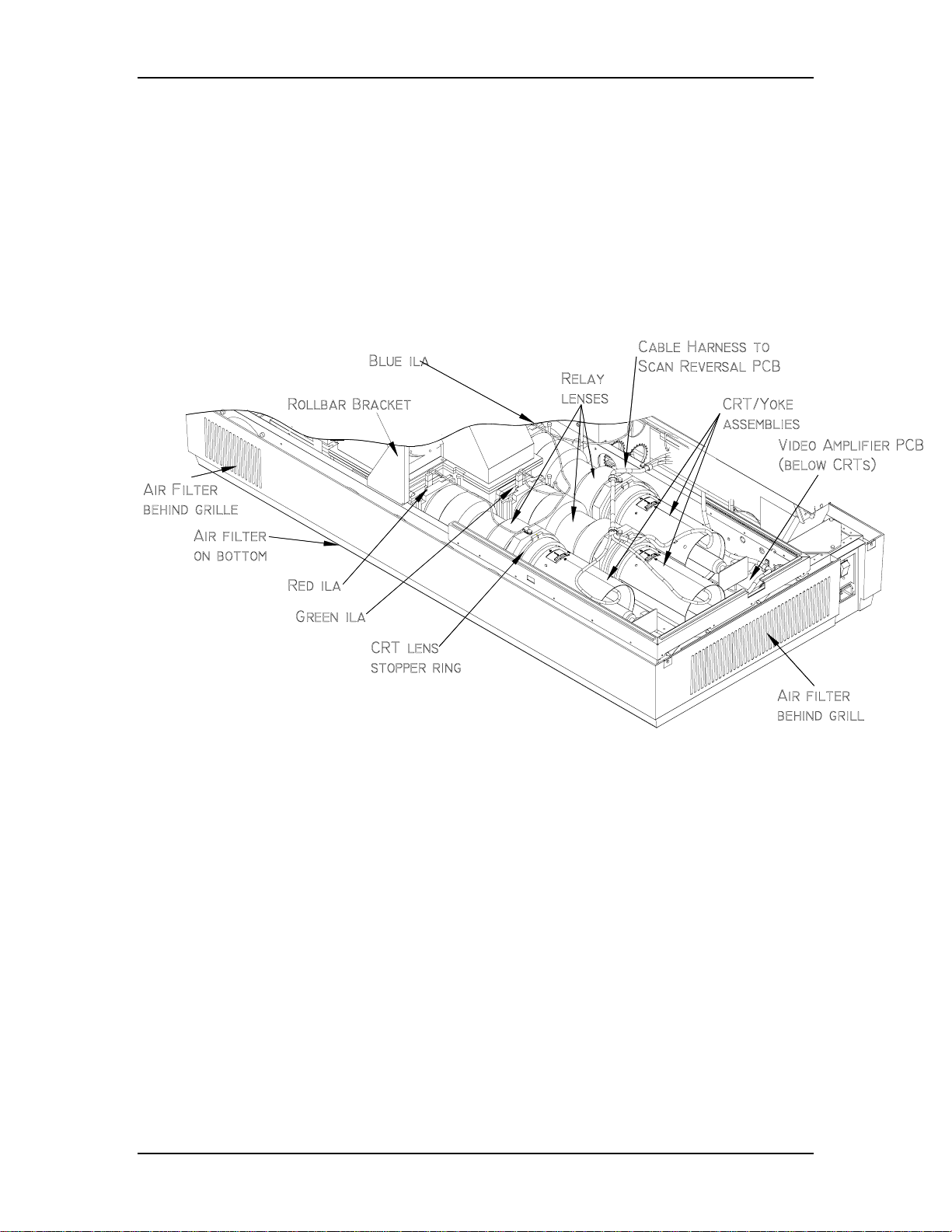
The Model 250 has three air filters (see Figure 2-2). The Air Filters filter the
incoming air to minimize the amount of dust and air-borne particles inside the
Model 250 Service Manual 2-7
Page 15
Chapter 2---System Description
projector. These air-borne particles can land on optics such as the ILA® and cause
large diffuse dark areas on the screen.
EMI Shield
The Model 250 has an EMI (Electro-Magnetic Interference) Shield that traps and
collects high frequency noise that is radiated by switching power supplies such as
the Arc Lamp Power Supply and the Low Voltage Power Supply. This high
frequency noise can interfere with the operation of radios, televisions, and other
electronic devices.
Figure 2-2
2-8 Model 250 Service Manual
Relative location of CRTs, Relay Lenses, ILA®s, and Air Filters.
Page 16

Chapter 2---System Description
Model 250 Service Manual 2-9
Page 17
3.0 Electrical
Contents
3.1 Safety............................................................................................................ 3-1
3.2 Incoming Power Circuit............................................................................... 3-2
AC Power Cord.......................................................................................... 3-2
AC Circuit Breaker.....................................................................................3-2
AC EMI Filter ............................................................................................ 3-2
3.3 Power Supplies............................................................................................. 3-3
Low Voltage Power Supply ....................................................................... 3-3
Arc Lamp Power Supply............................................................................3-5
High Voltage Power Supply....................................................................... 3-9
3.4 Igniter Assembly.......................................................................................... 3-15
Chapter 3---Electrical
3.1 Safety
review the chapter on Safety at the beginning of this manual.
that require projector covers to be off,
(ANSI/ASTM 10,000 volt rated) when working near the CRTs, Arc
Lamp, or power supplies. Wear safety goggles (rated X5) when
working anywhere near the light path from the arc lamp or the
projection lens
data be downloaded (
performing any of the following procedures. Exporting baseline source
setup data to disk is an excellent precautionary measure. It will save the
time of setting up new source file(s) in the case of an unexpected problem
CAUTION
WARNING
.
CAUTION
Exported, see section 8.2 Importing/Exporting
Before performing procedures in this chapter,
!
When performing procedures in this chapter
!!!
wear high voltage gloves
It is very strongly recommended that setup
!
) before
.
Model 250 Service Manual 3-1
Page 18

Chapter 3---Electrical
3.2.
Left/Right Orientation:
reference to standing at the rear of the projector, facing the screen.
Connectors
before pulling on the connector. The proper procedure is to push slightly IN on
the connector, then squeeze the tab, then pull the connector out.
on subassemblies and PCBs have tabs that must be released first
When referring to the left or right in this c hapter, it is with
Incoming Power Circuit
AC Power Cord
The Power Cord performs one basic function: to deliver the AC power from the
power source to the projector. It must be configured to meet the Electrical
Specifications for the region the projector will be used. The Power Cord type is
NEMA 5-20, 20A, 250A.
AC Circuit Breaker
The AC Circuit Breaker has two basic functions: one is to connect and disconnect
electrical power from the projector, the second is to protect the projector from
over-voltage conditions.
When the AC Circuit Breaker is in the OFF position, no electrical energy will
reach any part of the projector except for the AC Circuit Breaker. When the AC
Circuit Breaker is in the ON position, electrical energy goes to the AC Line Filter
and on to the Low Voltage Power Supply and Arc Lamp Power Supply. When the
AC Circuit Breaker is in the ON position but the projector has not received the
POWER ON command either from an IR Remote Control or from a PC or Laptop
computer, the projector is in Standby mode. In the Standby mode, the +5.1 V
Standby and the +24 V Standby Voltages maintain power to the CPU chips on the
System Controller PCB, the IR Detectors, and to the cooling fans.
The AC Circuit Breaker is rated at 90-264 Vac (RMS), 50/60 Hz. The current
rating is 13 Amps RMS at 90 Vac.
The power requirements of the Model 250 Projector are 200-264 Vac, 50/60 Hz,
single phase. The power consumption is rated at 2800-Watts maximum.
AC EMI Filter
The AC EMI (Electro-Magnetic Interference) Filter prevents switching noise
from a regulated power supply such as the Low Voltage Power Supply and the
Arc Lamp Power Supply, from returning to the AC power source. This switching
noise interferes with the operation of radios, televisions, and other electronic
appliances
3-2
Model 250 Service Manual
Page 19

3.3 Power Supplies
All Series 200 projectors including the Model 250 have three power supplies.
These include:
!
Low Voltage Power Supply
!
Arc Lamp Power Supply
!
High Voltage Power Supply
There is a fourth power supply, the Laser Power Supply, but that power supply is
used only for the Igniter Assembly during Arc Lamp lighting.
Low Voltage Power Supply (LVPS)
LVPS - Main Functions:
!
Provides all the low voltages needed by the projector.
!
Provides standby power (+5.1V) when the projector is OFF but the AC
Circuit Breaker is in the ON position.
Chapter 3---Electrical
!
Provides power (+24 V) for all cooling fans.
LVPS - Inputs
:
The Low Voltage Power Supply receives AC input power directly from the AC
Line Filter. The input range is from 220 VAC to 240 VAC, at 50/60 Hz.
/LV_ENA - from the System Controller PCB. This signal enables the LVPS when
the System Controller receives a Power On command.
/FAN_ENA - from the System Controller PCB. This signal enables the +24v
standby voltage for the projector fans.
/COVER_ON - signal enables the non-standby outputs.
/ = Active low
LVPS - Outputs:
!
+ 5.1VDC Main
!
+ 5.1VDC Stdby
!
+ 6.2VDC
!
± 15VDC
!
+ 24VDC
!
+ 80VDC
/LV_OK - this diagnostic signal tells the System Controller PCB the status of the
non-standby supply (all the outputs are working or not working).
Model 250 Service Manual 3-3
Page 20
Chapter 3---Electrical
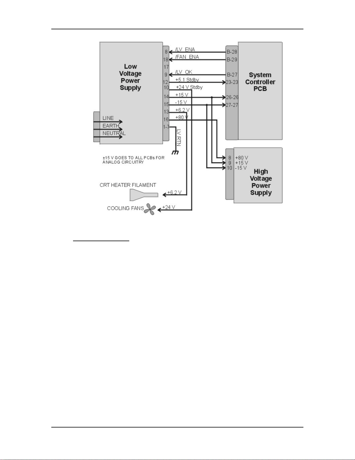
Figure 3-1
Low Voltage Power Supply I/O Diagram.
LVPS - Operation:
AC power is delivered to the Low Voltage Power Supply from the AC line filter.
The AC is rectified to a DC Voltage, filtered, and goes through a power factor
correction circuit to force the current waveform to follow the voltage waveform.
The +5.1V Standby is on whenever AC power is connected to the projector and
the circuit breaker on the rear panel is in the ON position. When the AC Circuit
Breaker is in the ON position, the LVPS supplies the +5.1 V to the System
Controller PCB. The System Controller PCB drives the /FAN_ENA signal to the
LVPS to turn on the +24V Standby power for the cooling fans. If the System
Controller PCB does not receive a POWER ON command from an IR remote
control or a PC, it waits about 10 minutes and then tells the LVPS (/FAN_ENA
goes high) to shut off +24V Standby power. This shuts off the cooling fans. More
importantly, after the System Controller PCB receives a POWER OFF command
it waits 10 minutes, and then tells the LVPS to shut off the cooling fans. This
gives the Arc Lamp and the PCBs time to cool down to avoid damage or
reduction of operating life.
When the projector receives a POWER ON command from an IR Remote Control
or PC, the System Controller PCB sends the /LV_ENA signal to the LVPS. The
Low Voltage Power Supply needs to receive the /LV_ENA from the System
Controller PCB and the /COVER_ON signal to activate all the non-standby
voltages. These include:
3-4
Model 250 Service Manual
Page 21

Chapter 3---Electrical
!
+5.1V for digital components
!
+6.2V for CRT filaments
!
±15V for analog circuits
!
+80V supply used by the High Voltage Power Supply, Video Amplifier
PCB, and the Horizontal/Vertical Deflection PCB.
LVPS - Service Adjustments
There are no service adjustments for the Low Voltage Power Supply.
LVPS - Remove and Replace
Tools Needed:
#2 Posi-drive Phillips-head screwdriver
Parts Needed:
Low Voltage Power Supply - p/n 102520
To remove the Low Voltage Power Supply:
1.
Power off the projector by IR Remote or PC, and allow the cooling fans to
run until they shut off.
2.
Turn the AC Circuit Breaker to the OFF position and unplug the AC
Power Cord.
3.
Remove the front cover (see Projector Covers section 6.1).
4.
Remove the lower-right-side panel by removing the 5 Pozi-drive screws
securing it.
5.
Remove the 5 Pozi-drive screws securing the EMI Shield. Slide the shield
to the left and remove it.
6.
Remove J76 (DC Output) and J75 (AC Input) from the left side of the
Low Voltage Power Supply.
NOTE
: These connectors may be a little difficult to remove and it may be
necessary to pull the LVPS partly out of the chassis in order to get a better
grip on the connectors.
7.
Carefully slide the Low Voltage Power Supply out of the projector.
8.
Reinstall the LVPS in reverse order. After installing a new LVPS, it may
be necessary to touch-up the Timing, Geometry, Electronic Focus, ILA
Bias/Sensitivity, Convergence, G2, and Shading.
Arc Lamp Power Supply (ALPS)
®
ALPS - Main Functions:
!
Provides ignition power to turn the Arc Lamp ON (via the Igniter).
!
Provides steady state power to maintain the Arc Lamp operation.
Model 250 Service Manual 3-5
Page 22

Chapter 3---Electrical
ALPS - Inputs:
AC input power: Directly from the AC Line Filter. The input range is from 220-
240 VAC, at 50/60 Hz.
/LAMP_ENA - from the System Controller PCB. Turns on the ALPS.
/COVER_ON - signal enabling the Arc Lamp Power Supply.
/LAMP_OK - the input is jumpered at the Arc Lamp Power Supply (tied to
ground) so it is always low.
/ = Active Low
ALPS - Outputs:
!
+170 VDC output during the boost phase to get Arc Lamp ignition. This
supplies the power for the Igniter.
!
Run Voltage - 25 to 31 V to maintain the arc lamp operation.
!
Current - 70 to 85 amps to maintain the arc lamp operation.
!
LAMP_OUT - Lamp output voltage, positive.
!
LAMP_RTN - Lamp return.
!
/LAMP_LIT - signal to System Controller PCB indicating that the Arc Lamp
is lit.
!
/LAMP_OK - signal to System Controller PCB (no real indication).
3-6
Model 250 Service Manual
Page 23
Chapter 3---Electrical
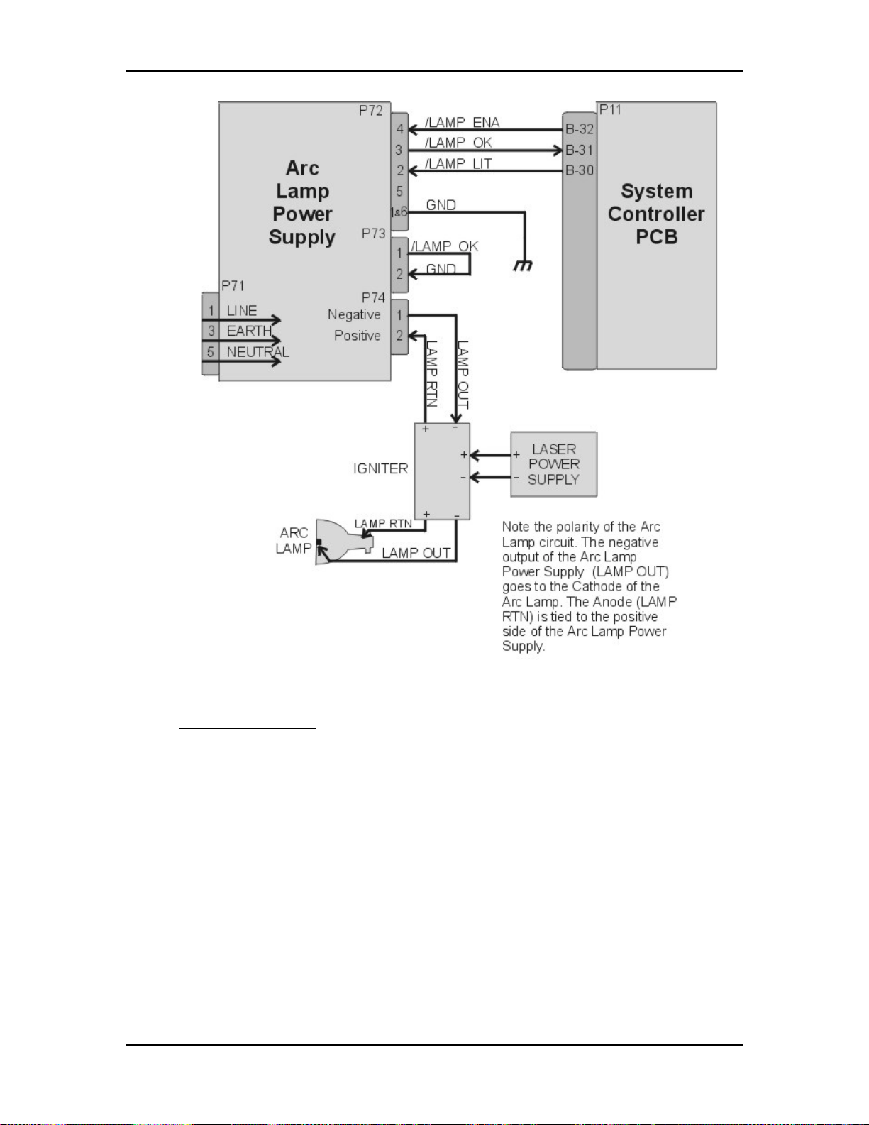
Figure 3-2
Arc Lamp Power Supply signals and voltages.
ALPS - Operation:
Three signals (/LAMP_ENA, /COVER_ON, and /LAMP_OK) are required in
order for the Arc Lamp Power Supply to light the Arc Lamp. The /LAMP_OK
(active low) input is jumpered to ground at the Arc Lamp Power Supply, so it is
always low. The Arc Lamp Power Supply sends the /LAMP_OK to the System
Controller PCB. The System Controller PCB then sends the /LAMP_ENA signal
back to the Arc Lamp Power Supply and activates the Arc Lamp Power Supply.
Once the Arc Lamp Power Supply receives the /LAMP_ENA signal from the
System Controller PCB, it supplies the +170 VDC boost voltage to the primary
coil of the Igniter. The Laser Power Supply charges up a capacitor. When the
capacitor reaches +5.5 kV, a spark gap arcs causing a very high voltage pulse
(approximately 32 kV) to be induced onto the secondary coil inside the Igniter.
This high voltage pulse ignites the Xenon Arc Lamp. Immediately after the Arc
Lamp lights, the voltage from the Arc Lamp Power Supply drops to about 25-31
volts at 70-85 amps. It will stay at this level during normal Arc Lamp operation.
Model 250 Service Manual 3-7
Page 24
Chapter 3---Electrical
The Arc Lamp Power Supply sends the
/LAMP_LIT signal back to the System Controller when the Arc Lamp is lit.
The Arc Lamp regulates its output to give a constant Arc Lamp power. If the Arc
Lamp has not lit within 20 seconds (/LAMP_LIT still high), the System
Controller PCB will try once more to re-initiate the sequence. If the Arc Lamp
still fails to light, an error code will appear on the back panel (see section 7.22
Error Codes).
The Arc Lamp Power Supply negative output goes to the Cathode of the Arc
Lamp. The positive output goes to the Anode of the Arc Lamp and is tied to
chassis ground.
The Arc Lamp Power Supply is shielded electrically and magnetically to prevent
noise or disturbances in the CRTs or other circuitry.
3-8
Figure 3-3
Arc Lamp Power Supply connections.
ALPS - Service Adjustments
The Arc Lamp Power Supply for the Model 250 is preset at the factory and does
not have any Service Adjustments. The output is programmed for a constant
2 kW. Arc Lamp replacement does not require any electrical readjustments.
ALPS - Remove and Replace
Tools Needed
#2 Pozi-drive Phillips-head screwdriver
Parts Needed
Arc Lamp Power Supply p/n - 105216
To remove the Arc Lamp Power Supply (ALPS):
1.
Power off the projector by IR Remote or PC, and allow the cooling fans to
run until they shut off.
Model 250 Service Manual
Page 25

Chapter 3---Electrical
2.
Turn the AC Circuit Breaker to the OFF position and unplug the AC
Power Cord.
3.
Remove the front cover (see section 6.1 Projector Covers ).
4.
Remove the lower-right-side panel by removing the five Pozi-drive screws
securing it.
5.
Remove the five Pozi-drive screws securing the EMI Shield. Slide the
shield to the left and remove it.
6.
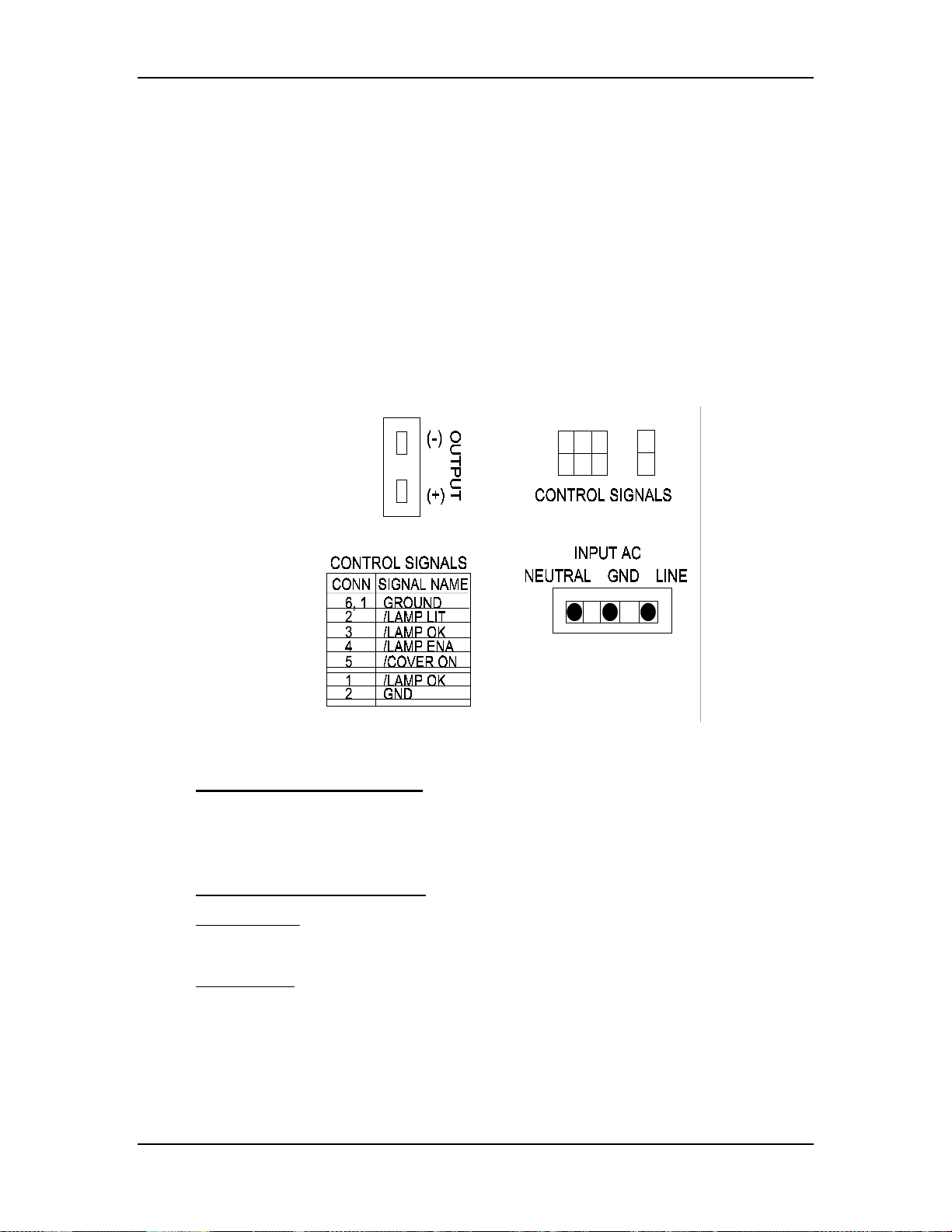
Disconnect the INPUT AC plug.
7.
Disconnect the two CONTROL SIGNALS cables. The /LAMP_OK signal
jumper is attached to the CONTROL SIGNAL cable by a cable tie. Do not
cut this cable tie.
8.
Disconnect the Arc Lamp Power Supply OUTPUT cables from the (+) and
(-) terminals. Take care not to damage the 470µf capacitor across the
output cables. The (+) cable has a red shrink tubing on it; the (-) has a
black shrink tubing on it.
NOTE
: The capacitor on the output of the Arc Lamp Power Supply filters
transient spikes from the Arc Lamp when it arcs. Re-attach the capacitor
with the Arc Lamp output leads during reinstallation of new Arc Lamp
Power Supply.
9.
Remove the 1 Pozi-drive Phillips-head screws from the bottom of the front
of the Arc Lamp Power Supply. The other screw was removed with the
EMI Shield.
10.
Carefully slide the Arc Lamp Power Supply out of the projector.
11.
Replace the Arc Lamp Power Supply in the reverse order.
High Voltage Power Supply (HVPS)
HVPS - Main Functions
The High Voltage Power Supply provides the following functions:
!
Phase locked loop circuit for synchronization of the High Voltage Power
Supply to the HVPS_SYNC
!
Generation of Anode voltages (25 kV) for all three CRTs (RGB)
!
Generation of Focus voltage (G3) (7 kV) for all three CRTs (RGB)
!
Generation of G2 (1200 V) supply voltage for the Video Amplifier PCB.
!
Generation of G1 (-150 V) supply voltage for the Video Amplifier PCB.
!
Dynamic Focus Amplifier using horizontal and vertical parabolas supplied to
the High Voltage Power Supply.
!
External CRT Protection and generation of /HV_OK signal
Model 250 Service Manual 3-9
Page 26
Chapter 3---Electrical
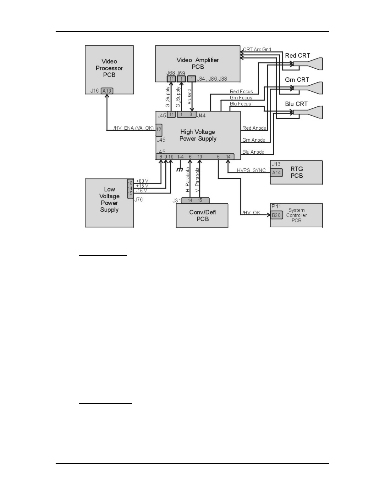
Figure 3-4
High Voltage Power Supply I/O signals.
HVPS - Inputs
HVPS_SYNC - this signal is generated on the Raster Timing Generator PCB.
Square wave HCT level with 50 or 33% duty cycle. The signal is synchronized to
horizontal sync.
/HV_ENA - The HVPS shutdown signal from the Video Amplifier PCB
(/VA_OK).
H_PARABOLA - The horizontal parabola from the Convergence Deflection PCB
used by the Dynamic Focus Amplifier.
V_PARABOLA - The vertical parabola from the Convergence Deflection PCB
used by the Dynamic Focus Amplifier.
± 15 V. - The power source for the analog circuitry in the High Voltage Power
Supply.
+ 80 V. - The input power for the High Voltage section of the High Voltage
Power Supply.
HVPS - Outputs
G1 Supply - goes to Video Amplifier PCB
3-10
G2 Supply - goes to Video Amplifier PCB
/HV_OK - goes to System Controller PCB
Model 250 Service Manual
Page 27

Chapter 3---Electrical
RGB Anode Voltage - goes directly to each CRT
RGB Focus Voltage - goes directly to each CRT
Arc Ground - The Arc Ground protection for each CRT from the Video Amplifier
PCB.
HVPS - Operation
The High Voltage Power Supply has three basic functions.
!
High Voltage Generation
!
Focus Voltages
!
High Voltage and CRT Protection
High Voltage Generation - The High Voltage Amplifier section converts the +80
V from the Low Voltage Power Supply, to 25 kV, and divides it into three outputs
for each CRT. It also uses the HVPS_SYNC signal from the Raster Timing
Generator PCB. This signal is synchronized to the horizontal sync to eliminate
one source of moving noise on the screen. The High Voltage section also supplies
the G2 Voltage for the Video Amplifier PCB.
Focus Voltages - The High Voltage Power Supply receives the horizontal and
vertical parabolas from the Convergence Deflection PCB and adds them together.
They are amplified and sent to the Focus Pack section. The Focus Pack section
couples the amplified parabola waveforms to the Focus Voltages. The Focus Pack
divides the Focus Voltage into three signals and outputs each signal to a CRT.
The DC Focus Voltages are manually adjusted as necessary.
The Arc Ground signal goes to the Video Amplifier PCB and from there, connects
to the CRT. It provides a direct return path for arc currents in the event of internal
CRT arcing.
High Voltage and CRT Protection - The High Voltage Power Supply receives a
/HV_ENA (/VA_OK) signal from the Video Amplifier PCB. This signal goes to
the Protect OR section. The Protect OR section also checks the incoming +80 V.
from the LVPS for an overcurrent condition. The Protect OR section also
monitors the high voltage output for an overvoltage condition. If any of these
checks shows a problem the Protect OR section shuts down the high voltage
amplifier. The Protect OR section outputs the /HV_OK signal telling the System
Controller PCB that the High Voltage Power Supply is functioning properly.
HVPS - Service Adjustments
Normally, the only High Voltage Power Supply adjustments are for CRT Focus.
The CRT Focus Voltage adjusts are mechanical potentiometers located on the
side of the High Voltage Power Supply (see Figure 3-5) that adjust the focus for
each CRT. The CRT Focus Voltage adjustments are detailed in the CRT Section
(see section 5.10 CRT/Yoke Assemblies).
Model 250 Service Manual 3-11
Page 28
Chapter 3---Electrical
HVPS - Remove and Replace
Tools Needed
#1 Pozi-drive Phillips-head screwdriver
#2 Pozi-drive Phillips-head screwdriver
small Flathead screwdriver
Parts Needed
High Voltage Power Supply p/n 102566
To remove the High Voltage Power Supply:
1.
Power off the projector by IR Remote or PC, and allow the cooling fans to
run until they shut off.
2.
Turn the AC Circuit Breaker to the OFF position and unplug the AC
Power Cord.
3.
Remove the front cover.
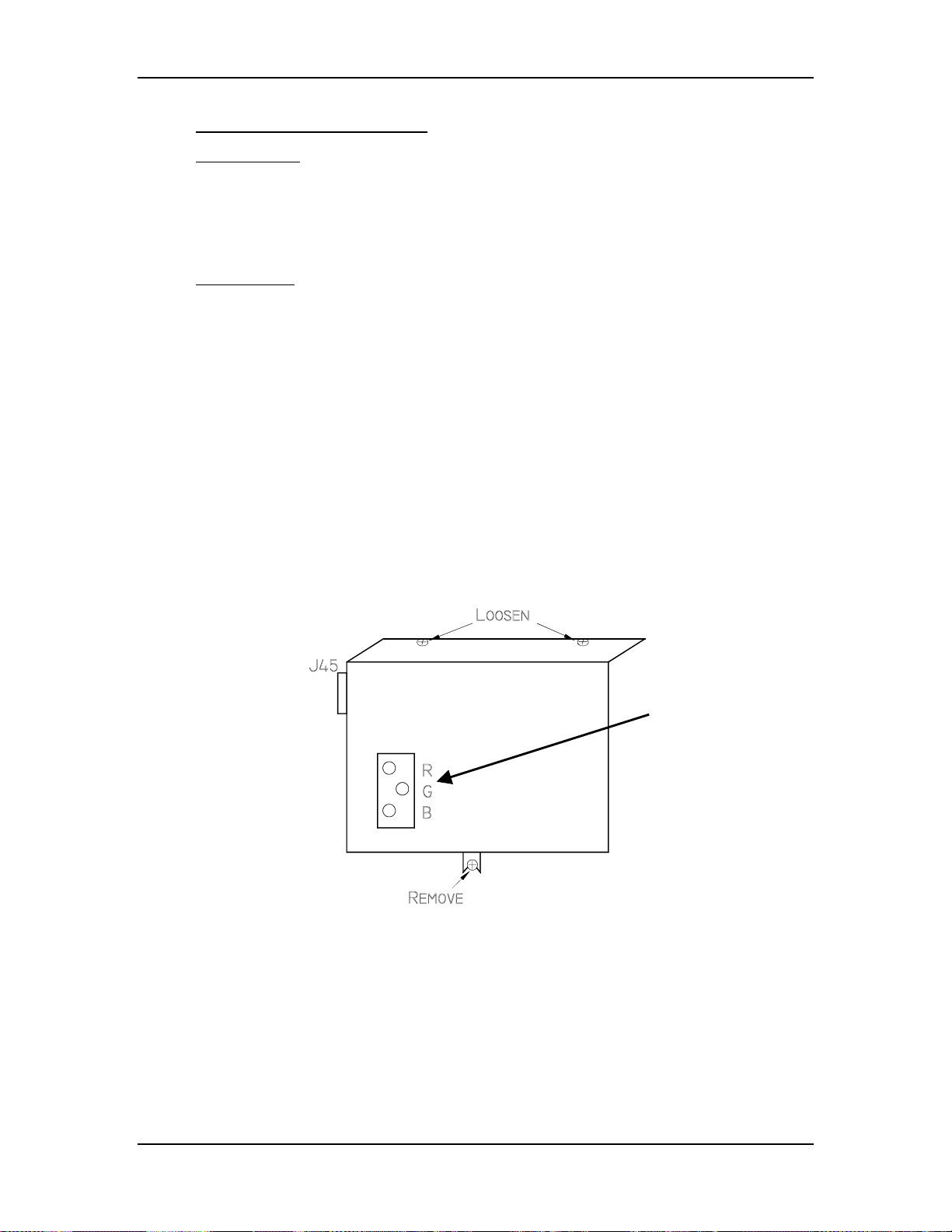
4.
Remove the High Voltage Power Supply cover (see Figure 3-5) by
removing the 1 Pozi-drive screw that secures the HVPS at the bottom of
the cover and loosening the 2 Pozi-drive screws at the top of the front flap.
Figure 3-5
Electronic
Focus
Adjustment
High Voltage Power Supply cover.
3-12
Model 250 Service Manual
Page 29
Chapter 3---Electrical
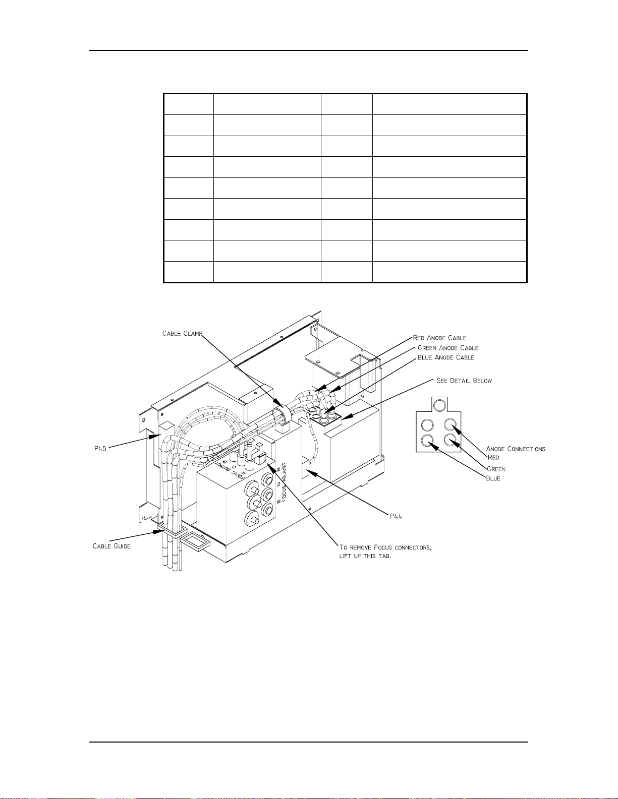
Table 3-1
HVPS - P45 I/O Pinout
PIN # Description PIN # Description
1 GND (+80V) 9 +15V
2 GND (+15V) 10 -15V
3 GND (-15V) 11 G1 SUPPLY
4 GND (G1) 12 /HV_ENA
5 /HV_OK 13 V PARABOLA
6 H PARABOLA 14 H DRIVE (HVPS_SYNC
7 GND (DAF)
8 +80V
Figure 3-6
5.
Carefully slide the cover upward and outward to remove it.
NOTE
6.
Disconnect the three CRT Anode Cables.
7.
Disconnect P44-G2 Out (at the middle-front of the HVPS).
8.
Unsnap the cable clamp at the top of the HVPS.
9.
Remove the Anode Cables and the P44 cable from the cable clamp.
Model 250 Service Manual 3-13
: Refer to Figure 4-5 for the remainder of this procedure.
High Voltage Power Supply.
Page 30

Chapter 3---Electrical
10.
Disconnect P45 (“Control”) at upper left of HVPS.
11.
Disconnect and label the three Focus cables. The square tabs on these
cables (see Figure 3-6) may have to be lifted up. Gently pry up with a
small Flathead screwdriver.
12.
Remove all the cables from the slot in the cable guide located on the left
side of the HVPS.
13.
Verify that all plugs and cables are removed and out of the way so the
HVPS is free to be removed.
14.
Loosen (do not remove) the two Posi-drive screws (at the bottom of the
HVPS) that secure the HVPS metal housing to the projector.
15.
Remove the two Posi-drive screws that hold the top of the HVPS metal
housing to the projector frame.
16.
Grasp the HVPS at the bottom and lift upward and outward so that it slides
away from the bottom screws.
17.
Reinstall the High Voltage Power Supply in the reverse order.
NOTE
!
: When reinstalling the High Voltage Power Supply:
Make sure it slides over the bottom screws and the lip at the top of the
projector frame.
!
Make sure each anode cable “snaps” back into its receptacle. The
receptacles are about 2” inside the hole where the cable goes.
!
Make sure the rear flap on each focus cable connector snaps over the
square socket securely. Wiggle the connector a little to make it fits
securely.
18.
Replace the HVPS cover.
19.
Replace the projector covers.
20.
After replacing the HVPS, check and adjust Electronic Focus as necessary.
3-14
Model 250 Service Manual
Page 31

3.4 Igniter Assembly
The Igniter Assembly consists of the Igniter and the Laser Power Supply. The
Igniter and Laser Power Supply are replaced as one unit.
Igniter Assemby - Main Functions:
!
Generates 32 kV pulse to light Arc Lamp Power
!
Acts as link between Arc Lamp Power Supply and Arc Lamp during normal
Arc Lamp operation
Igniter Assembly - Inputs
!
+170 V - From the Arc Lamp Power Supply during Arc Lamp lighting.
!
25-31 V at 70-85 A - From Arc Lamp Power Supply during normal Arc Lamp
operation.
Igniter Assembly - Outputs
!
32 kV - to the Arc Lamp during Arc Lamp lighting.
!
25-31 V at 70-85 A - From Arc Lamp Power Supply during normal Arc Lamp
operation.
Chapter 3---Electrical
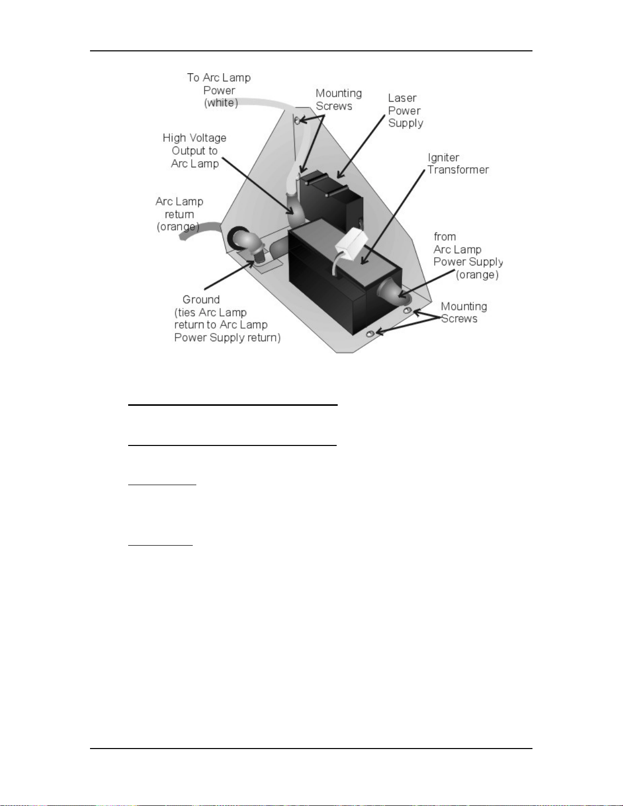
Igniter Assembly - Operation
The Igniter has two functions: to light the Arc Lamp and to act as a link between
the Arc Lamp Power Supply and the Arc Lamp during normal Arc Lamp
operation. The Igniter contains the spark gap and the step-up transformer that
supplies the 32 kV pulse that lights the Arc Lamp. During lighting of the Arc
Lamp, the Arc Lamp Power Supply receives the /LAMP_ENA signal from the
System Controller PCB, it sends a +170 VDC boost voltage to the primary coil of
the Igniter. The Laser Power Supply charges up a capacitor. When the capacitor
reaches +5.5 kV, the spark gap arcs causing a very high voltage pulse
(approximately 32 kV) to be induced onto the Igniter Transformer step-up
(secondary) coil. The high voltage pulse goes to the Anode of the Arc Lamp. The
spark generated by the 32 kV pulse creates an arc inside the Xenon bulb that
ignites the Arc Lamp.
Model 250 Service Manual 3-15
Page 32
Chapter 3---Electrical
Figure 3-7
Igniter Assembly.
Igniter Assembly - Service Adjustments
There are no service adjustments performed on the Igniter Assembly.
Igniter Assembly - Remove and Replace
Replace the Igniter and the Laser Power Supply as one unit.
Tools Needed
2 - 7/16-inch wrench (one open end wrench)
#1 Pozi-drive Phillips-head screwdriver
Parts Needed
Igniter Assembly p/n 106570
To remove the Igniter Assembly
1. Power the projector Off by IR Remote or PC, and allow the cooling fans
to run until they shut off.
2. Turn the AC Circuit Breaker to the OFF position and unplug the AC
Power Cord.
3-16
3. Remove the front cover (see Projector Covers section 6.1).
4. Disconnect the white Anode cable from the output of the Igniter
Transformer using the 7/16-inch wrench. Use one wrench to hold the
inside nut and the other wrench to loosen the outside nut.
Model 250 Service Manual
Page 33

Chapter 3---Electrical
5. Disconnect the orange cable attached to the input side of the Igniter
Transformer using the 7/16-inch wrench. This cable will have black shrink
sleeving on it. It goes to the negative terminal of the Arc Lamp Power
Supply.
6. Disconnect the orange Cathode cable from the Igniter ground post using
the 7/16-inch wrench. Remove the other orange cable that goes to the
positive terminal of the Arc Lamp Power Supply.
7. Remove the five #1 Pozi-drive Phillips-head screws.
8. Lift the Igniter Assembly out of projector.
9. Reverse the procedure to install the Igniter Assembly.
Model 250 Service Manual 3-17
Page 34
4.0 Optical
Contents
4.1 Arc Lamp......................................................................................................4-2
4.2 Optical Path.................................................................................................. 4-7
4.3 ILA®.............................................................................................................4-13
4.4 Relay Lenses ................................................................................................ 4-20
4.5 Projection Lens............................................................................................. 4-20
Chapter 4---Optical
CAUTION!
review the chapter on Safety at the beginning of this manual.
WARNING!!!
that require projector covers to be off, wear high voltage gloves
(ANSI/ASTM 10,000 volt rated) when working near the CRTs, Arc Lamp,
or power supplies. Wear safety goggles (rated X5) when working
anywhere near the light path from the arc lamp or the projection lens.
Dangerous levels of ultraviolet and infrared radiation, dangerous glare, very high
temperatures (180°C to 300°C) and high internal gas pressure are present at the
Xenon Arc Lamp. The lamp is contained in a protective reflector-housing module
and should not be operated outside this housing or outside of the projector.
When replacing the Arc Lamp, replace it as an entire module, as shown in this
manual. Do not open the lamp housing or attempt to replace the Arc Lamp
inside its module! Do not touch the Arc Lamp, or any connections, when the
lamp is ignited or is arcing.
Any servicing of the Arc Lamp must remain restricted to Hughes-JVC Certified
Technicians.
Before performing procedures in this chapter,
When performing procedures in this chapter
Model 250 Service Manual 4-1
Page 35

Chapter 4---Optical
4.1 Arc Lamp
The Arc Lamp is the beginning of the high intensity Light Path. It is located
inside a housing on the right side of the Optical Support Assembly (see Figure
4-5).
Arc Lamp - Main Functions:
The Arc Lamp is a single component composed of a Xenon gas bulb at the center
of a compound elliptical reflector. It supplies the high intensity white light used
by the projector to put a very bright image on the screen. The expected 50% life
(half of initial light output) of an Arc Lamp is approximately 1000 hours.
Arc Lamp - Inputs
!
32 kV pulse to light the Arc Lamp Power Supply
!
2 kW constant power during normal operation
Arc Lamp - Operation
The Arc Lamp Power Supply and the Igniter Assembly work together to produce
a 32 kV pulse that ignites the Arc Lamp. After the Arc Lamp lights, the voltage
from the Arc Lamp Power Supply drops to a constant 25-31 volts at 70-85 amps.
It will stay at this level during normal Arc Lamp operation.
Arc Lamp - Service Adjustments
When a new Arc Lamp is installed, it will need to be aligned using the Arc Lamp
adjustment fixture located inside the Arc Lamp housing (see Figure 4-2).
Arc Lamp Adjustment
Tools Needed
Large Flatblade screwdriver
4-mm Hex-head wrench
Equipment Needed
Minolta Illumination Meter T-1 or equivalent
To align the Arc Lamp:
1. Remove the front cover (see Section 6.1).
2. Loosen the spider lock down bolt (see Figure 4-4).
3. Power the projector ON and let it run for 15 minutes to stabilize.
4. Verify that the "Shutters on Hide" box is checked in the System-
Preferences menu, then use the RGB key and the HIDE key to hide Red
®
and Blue. This prevents light coming from the Red and Blue ILA
s.
4-2
5. Open the fan door of the Arc Lamp Enclosure housing using the large
Flatblade screwdriver to rotate the retaining screws 90° This gains access
to the three Arc Lamp alignment screws. The Arc Lamp fan disconnects
when this door is opened.
Model 250 Service Manual
Page 36

Chapter 4---Optical
CAUTION
Fan disconnection is acceptable for a short
!
period of time only (preferably <20 minutes--maximum 45 minutes).
WARNING!!!
Dangerous levels of ultraviolet and
infrared radiation, dangerous glare, very high temperatures (180°C to
300°C) and high internal gas pressure are present at the Xenon Arc
Lamp. Protect eyes from ultra violet light and infrared light by using X5
(375 to 700 nanometers), ANSI approved, shade goggles when
actually working on the projector near the arc lamp source.
6. Access the "Shutters on Hide" box again from the System-Preferences
menu and uncheck the box, then use the RGB and HIDE keys to hide
Green. This mutes video from the Green CRT but leaves the Green shutter
®
open to allow Arc Lamp light from the Green ILA
to display on the
screen.
7. Select ILA® Bias from the System-Factory Adjustments menu. Record the
current ILA® bias level. Return to this bias level when this adjustment is
complete. Record only the Green ILA® bias value because Red and Blue
will return to their original levels when Green is reset.
8. Use the up-arrow key and adjust the ILA® bias for Green for maximum
light output.
9. Adjust the Arc Lamp alignment screws (see Figure 4-2) to center the "hot
spot" (brightest area). Figure 4-1 illustrates a "hot spot" on the screen.
NOTE:
It is easier to perform the following procedure with one person
standing in front of the screen holding a light meter and another person
making the adjustments to the Arc Lamp.
10. Use the light meter to locate the brightest area or “hot spot”, (see Figure
4-1). Move the light meter around the screen to determine where the hot
spot is located. The “hot spot” will be where the light reading is highest.
11. Adjust screw 1, 2, or 3, (see Figure 4-2) to move the hot spot to the center
of the screen. Moving the “hot spot” will generally require adjusting two
or more screws. Adjusting all three screws adjusts the Arc Lamp on the zaxis. Adjusting the three screws clockwise increases light output and
rolloff.
12. Check for maximum brightness and readjust the z-axis as necessary after
setting the x-axis and again after setting the y-axis.
13. Tighten spider lock down bolt.
Model 250 Service Manual 4-3
Page 37

Chapter 4---Optical
Hot spot
off-center
Figure 4-1
Arc Lamp “Hot Spot” (brightest area) is off-center vertically and
horizontally. Adjust to center the “hot spot”.
Figure 4-2
Arc Lamp alignment fixture.
4-4
Model 250 Service Manual
Page 38

Chapter 4---Optical
Figure 4-3
Arc Lamp Assembly access door.
Arc Lamp - Remove and Replace
The Arc Lamp Enclosure Assembly consists of the Xenon Arc Lamp module and
blower. Replace the blower together with the Arc Lamp Module.
Tools Needed
7/16 inch wrench
#1 Pozi-drive Phillips-head screwdriver
Diagonal wire cutters (or equivalent)
Parts Needed
Arc Lamp p/n 106298
WARNING!!!
Dangerously bright light and high current
exist in this area of the projector. Before proceeding with the removal of
any subassemblies below, verify that the circuit breaker at the rear of the
projector is turned off and the power plug is removed from the AC outlet.
To Remove the Arc Lamp:
1.
Power off the projector by IR Remote or PC, and allow the cooling fans to
run until they shut off.
2.
Turn the AC Circuit Breaker to the OFF position but leave the AC Power
Cord plugged in to maintain chassis ground.
3.
Remove the front cover (see Section 6.1).
4.
Disconnect the white Anode cable from the Igniter, using the 7/16-inch
wrench (see Figure 3-7).
Model 250 Service Manual 4-5
Page 39

Chapter 4---Optical
5.
Disconnect the orange Cathode cable from the Igniter, using the 7/16-inch
wrench (see Figure 3-7).
6.
Cut the cable tie that is wrapped around the ferrite inductor (metal tube
with white cap below the blower).
7.
Disconnect the Arc Lamp door fan cable. This cable runs through the door
and out the bottom of the Arc Lamp Assembly housing (below the right
side inFigure 4-3). It provides power to the Arc Lamp door fan through the
white socket shown to the right of the Arc Lamp fan in Figure 4-3.
Disconnect the cable at the socket connection below the Arc Lamp
housing. Disconnect the top fan cable.
8.
Disconnect large blower fan connector.
9.
Remove the FA shield from the top of the Arc Lamp. Three #1 Pozi-drive
Phillips-head screws hold the FA shield in place (see Figure 4-4).
10.
Remove the two retaining bolts for the Arc Lamp, using a 10-mm socket
and driver.
11.
Reverse the procedure to install the Arc Lamp. Check and adjust the Arc
Lamp alignment after replacing. There is no Arc Lamp current adjustment.
4-6
Model 250 Service Manual
Page 40
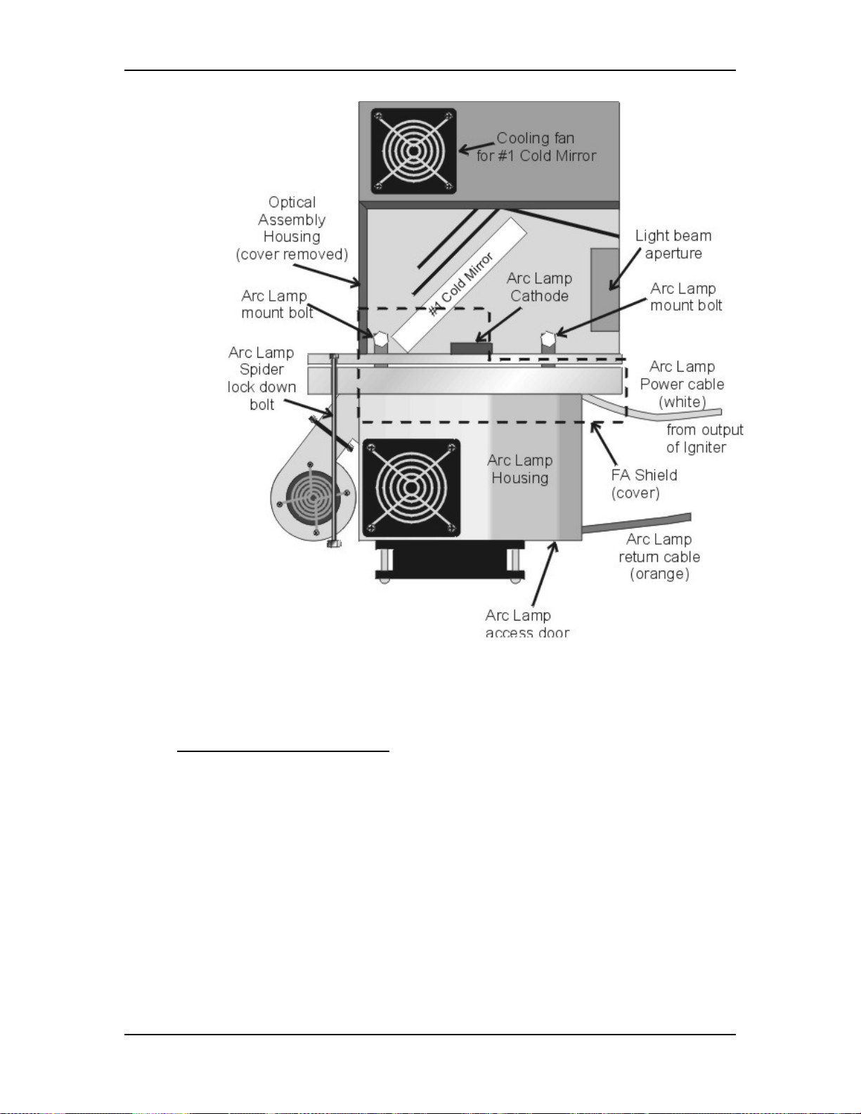
Chapter 4---Optical
Figure 4-4
Arc Lamp Assembly top view.
4.2 Optical Path
Optical Path - Main Function
!
Transports the Arc Lamp high intensity light from the Arc Lamp to the
ILA® and from the ILA® to the Projection Lens
!
Removes the Infrared light that contains most of the heat
!
Removes the unwanted Ultraviolet light
!
Condenses the white light using the Light Pipe for a uniform output
!
Separates the white light into its RGB component colors using Dichroic
Beamsplitters.
!
Polarizes each of the component RGB light beams
!
Combines the component RGB image beams into one beam and delivers
that to the Projection Lens.
Model 250 Service Manual 4-7
Page 41
Chapter 4---Optical
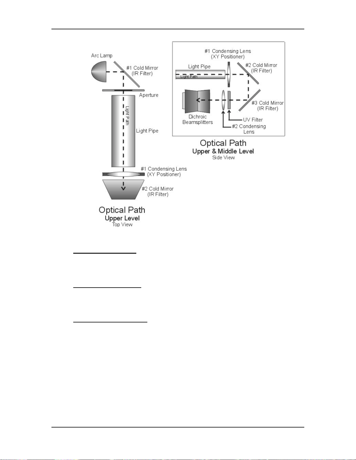
Figure 4-5
Upper level view of Optical Path (top view).
Optical Path - Inputs
Arc Lamp high intensity white light
Component RGB Image light from each of the ILA
®
Optical Path - Outputs
Component RGB polarized light to the ILA
®
Output image light to the Projection Lens
Optical Path - Operation
The light travels from the Arc Lamp into the Optical Path (see Figure 4-5). The
light reflects off a cold mirror and passes through a light pipe. From the Light
Pipe, the light passes through a Condensing Lens .The Condensing Lens also acts
as a XY Positioner. The function of the XY Positioner is to aim the light beam
down the optical path and center it on the face of the ILA®.
After being positioned by the Condensing Lens, the light then reflects off two
more Cold Mirrors, losing more Infrared light. It passes through another
Condensing Lens and into the Dichroic Beamsplitter Assembly.
4-8
Model 250 Service Manual
Page 42

Chapter 4---Optical
The Dichroic Beamsplitter Assembly separates the white light into its red, green,
and blue components. Each component light beam goes into the Prism Assembly
where it is polarized.
Light can be viewed as having two electromagnetic components: a Horizontalelectric field and a Vertical-electric field. These fields are perpendicular to each
other. When unpolarized light travels through a polarizing beamsplitter, one of
these fields is reflected and one is transmitted or passes through the beamsplitter.
Upon striking the Prepolarizer, the Vertical field is reflected and is wasted, the Pelectric field is passed through the Prepolarizing Beamsplitter and continues on to
the Main Polarizer. The Main Polarizing Beamsplitter (PBS) is rotated 90° from
the Pre-Polarizing Beamsplitter so the Horizontal field that was transmitted
through the Prepolarizer is reflected by the Main Polarizer. The reflected
polarized light, either red, green or blue, leaves the PBS and goes directly into the
ILA® (see Figure 4-6 and Figure 4-7).
Each color exits the Prism Assembly and enters an ILA® where the Liquid Crystal
in the ILA® rotates the polarized light. The image light striking the input side of
the ILA® modulates the polarized light. The image on the input of the ILA
®
originates as a image signal and is transformed into an image by the CRT. The
image from the CRT passes through the Relay Lens and is focused onto the input
side of the ILA®. The modulated image light leaves the output side of the ILA
®
and re-enters the Prism Assembly where all three colors combine in the 4P
combining optic. The image light exits the Prism Assembly, passes through the
Projection Lens, and is projected out on the screen (see Figure 4-7).
WARNING!!!
Wear safety goggles (rated X5) when
working anywhere near the light path from the arc lamp or the projection
lens.
DO NOT open any of the Optical Support Assembly covers while the
projector is ON. The bright light can cause severe eye damage.
Model 250 Service Manual 4-9
Page 43

Chapter 4---Optical
4-10
Figure 4-6
Optical Path
Model 250 Service Manual
Page 44

Chapter 4---Optical
Figure 4-7
Optical Path
Optical Path - Service Adjustments
Tools Needed
3-mm Hex wrench
Parts Needed
No serviceable parts
The one adjustment that can be performed on the optical path is with the XY
Positioner that moves the #1 Condensing Lens in the X- and Y-axis. The XY
Model 250 Service Manual 4-11
Page 45

Chapter 4---Optical
Positioner adjusts the light beam coming out of the Light Pipe so that it projects
squarely onto the face of the ILA®.
NOTE:
Do not adjust the XY Positioner unless there is a dark edge visible on
screen.
If the XY Positioner is misaligned, there will be a dark edge on the left, right, top
or bottom edge caused by the edge of the Light Pipe. Perform the Arc Lamp
alignment before adjusting the XY Positioner unless the dark edge makes Arc
Lamp alignment difficult or impossible.
To adjust the XY Positioner:
1. Turn the projector ON and allow it to stabilize for at least 15 minutes.
2. Check the screen for dark edges on the top, bottom, left, or right. Check
the screen with all three colors, using the Variable Flat Field (test pattern
#4) or with ILA® bias only. The dark edge will be obvious in either mode.
3. Remove the front cover.
4. There are four access holes; two with small notches on the top of the hole
and two without notches (see Figure 4-8). Use the two access holes
without notches. These holes are for full aperture ILA®s. The upper access
hole is for vertical adjustment; the lower one is for horizontal adjustment.
5. Insert a 3-mm (long shank) Hex-head wrench into either the horizontal or
vertical access hole and adjust the XY Positioner until the dark edge
moves off the screen.
4-12
Figure 4-8
XY Positioner adjust holes.
Model 250 Service Manual
Page 46

Chapter 4---Optical
4.3 ILA
ILA® Main functions
ILA® Inputs
Arc Lamp light - High intensity polarized Red, Green or Blue light from the
Prism Assembly.
Image light - Red, Green, or Blue image light from the CRTs.
ILA® Bias Voltage and Frequency - 10-13 Vac at 2 kHz
ILA® Outputs
®
!
Modulates image light from the CRT onto the high intensity polarized
light from the Arc Lamp
!
Reflects high intensity light received from the Prism Assembly back into
the Prism Assembly after modulating with image light
!
Adjustable bias voltage and frequency (ILA® Sensitivity)
!
Adjustable offstate with Super Contrast ILA®s
!
Image light from CRT is blocked from output. Image is electrostatically
coupled to output
Image light - High intensity polarized image light output to the Prism Assembly
and then to the Projection Lens and screen.
Figure 4-9
ILA® structure
Model 250 Service Manual 4-13
Page 47

Chapter 4---Optical
ILA® Operation
The ILA® plays a critical part in bringing the image to the screen. The ILA
receives the image light when the CRT projects the image through the Relay Lens
and focuses it onto the photoconductive layer on the input side of the ILA®. The
image does not pass directly through the ILA® but is transferred by a change of
impedance of the photoconductive layer to the Liquid Crystal Layer on the output
side of the ILA®. The light coming from the Arc Lamp enters the output side of
the ILA® and passes through the Liquid Crystal layer. Here the polarized light is
rotated according to the orientation of the liquid crystal molecules. It then reflects
off the mirror and passes back through the liquid crystal layer. The polarized light
it is rotated again and then exits the ILA®. The amount the liquid crystal rotates
the polarized light depends on the ILA® Bias, ILA® Sensitivity (frequency), and
CRT brightness (Sensitivity and Threshold).
®
Service Adjustments
ILA
ILA® Bias and Sensitivity Adjustment
The ILA® has adjustable bias and frequency (sensitivity). The ILA® bias and
sensitivity are adjusted by software through the menu (see Model 250 User’s
Guide, section 5.6 Setup Adjustments). The ILA® bias is individually adjustable
for each ILA®; the ILA® sensitivity (frequency) adjusts all the ILA®s together.
®
Super Contrast ILA® Compensator Adjustment
The offstate level can be adjusted on Super Contrast ILA®s. The Compensator
adjustment moves a lever on the top of each Super Contrast ILA® to a null
position. The null position is where the offstate level is as dark as possible. The
Compensator is set at the factory and should not need adjustment. Perform this
procedure when replacing an ILA® assembly or if the Compensator adjustment
lever has been inadvertently moved.
To set the Super Contrast ILA® Compensator:
1. Power the projector ON and allow it to stabilize for at least 30 minutes.
2. Remove the rear cover and tilt the Electronics Module up.
3. Under the System-Preferences menu, verify that the "Shutters on Hide"
box is checked.
4. Use the HIDE key to hide red and blue.
®
5. Disconnect the connector from the top of the green ILA
6. Move the Compensator lever (this lever is just in front of the ILA
assembly.
®
connector) to the right and left until the darkest level appears on the
screen.
®
7. Reconnect the ILA
8. Repeat the above steps for the red ILA
connector to the green ILA®.
®
and blue ILA®. Block the light
from the other two ILA®s each time, using the HIDE key.
4-14
9. Replace the rear cover.
Model 250 Service Manual
Page 48

Chapter 4---Optical
NOTE:
Reset the ILA® bias after setting the Compensator and check G
2
Sensitivity Offset, and Threshold Offset level (see Model 250 User’s
Guide, section 5.8 Black Level G2 and Sensitivity Offset).
ILA® Overlap
This adjustment positions the ILA® assemblies in their sockets so that the image
from each ILA® will overlap (be placed on top of) the other two ILA®s. Make this
adjustment whenever replacing an ILA®.
Tools Needed
4-mm hex-head wrench
Flathead screwdriver
Parts Needed
No parts are needed
To determine if this adjustment is necessary:
1. Power the projector ON and allow it to stabilize for at least 30 minutes.
2. Record the value of the ILA® bias for red, green and blue. Return the
ILA®s to these levels when this procedure is complete.
3. Under the System-Preferences menu, verify that the “Shutters on Hide”
box is unchecked.
4. Use the HIDE key to hide red, green and blue.
5. Increase the ILA® bias for all three colors to maximum. The image on the
screen should be white with some colors at the edges.
6. Check the right, left, top, and bottom edges of the images on the screen.
Using the green image as a reference, compare the edges of the red and
blue image to the green image.
NOTE:
7.
If the green ILA® has been replaced, reference green to the blue or
red image.)
8. If there is a red or blue border on the left, right, top or bottom edge, the
®
s overlap and need adjustment. If both the red and blue overlap, the
ILA
border will be yellow. In either case, proceed with the adjustment below.
9. If there is no overlap, reset the ILA® biases to their previous levels from
Step 1.
To perform an ILA
®
Overlap adjustment:
10. Continue with all three colors hidden.
®
11. Loosen the two wing nuts at the top of the ILA
assembly (see Figure
4-10).
12. If the overlap is at the left or right, grasp the ILA
®
assembly and slide it to
the right or left so that the edges coincide with the edges of the other two
ILA® assemblies.
Model 250 Service Manual 4-15
Page 49

Chapter 4---Optical
To avoid damaging the connector,
not
the connector at the top.
grasp the ILA
Figure 4-10
CAUTION!
®
assembly itself,
ILA® Assembly top view. The overlap screws shown are under
the ILA®. They are visible only after the ILA® assembly is removed.
13. If the overlap is at the top or bottom, be sure the projector is level. Slide
the spring clip (see Figure 4-10) at the top of the ILA® assembly back.
14. Loosen the two hex nuts, using a 4-mm hex-head wrench.
WARNING
!!!
Always wear an ANSI/ASTM 10,000
volt rated safety glove when working around CRTs due to the High
Voltage present there.
15. Slide the ILA®/Relay Lens/CRT Assembly back and remove the ILA
®
assembly (it will slide out with some resistance).
16. There are two adjustment screws at the bottom of the ILA® assembly that
move the ILA
®
up or down. Turn these screws in or out very slightly to
allow the ILA® to seat lower or higher, as necessary.
®
17. Reinstall the ILA
assembly, slide the ILA®/Relay Lens/CRT Assembly
forward and replace the spring clip.
18. Repeat Step 4 as necessary.
4-16
Model 250 Service Manual
Page 50

Chapter 4---Optical
19. Retighten the two wing nuts and tighten the two hex nuts.
20. Reset the ILA® biases to their previous levels from Step 2.
ILA® Back Focus Adjustment
The ILA® Back Focus adjustment moves the ILA®/Relay Lens/CRT assemblies
forward or backward as one unit to focus the ILA® output on the screen. When
using a zoom lens this adjustment allows the zoom lens’ tracking to remain
focused on the screen throughout the entire zoom range. Use the Focus Pattern
(Test Pattern #6) to perform this adjustment one color at a time. The procedures
below perform the ILA® Back Focus for the Green lens. The first procedure is for
a zoom lens. The second procedure is for a fixed lens.
For best results, perform ILA® Back Focus procedure with two people: One
person to stand in front of the screen to observe Spacer Balls and the other to
move the ILA®/Relay Lens/CRT assemblies back and forth. This is a factory-set
adjustment, but may need some touch-up in the field.
Tools Needed
4-mm Hex wrench
2.5-mm Hex wrench
Parts Needed
No parts are needed
To adjust the ILA® Back Focus for a Zoom Lens:
1. Power the projector ON and allow to stabilize for at least 15 minutes
2. Remove the Rear Cover and tilt up the Electronic Module.
3. Hide Red and Blue. View Green.
4. Select the Focus Pattern (Test Pattern #6).
5. Select Projection Lens from the menu.
6. Use the up/down arrow keys to zoom the Projection Lens to full telephoto
position (smallest image).
7. Use left and right arrows to focus the projection lens to get sharply
focused spacer balls.
NOTE:
Spacer balls separate the layers inside the ILA
®
Assembly. They
are tiny, random, irregularly shaped spots that are visible throughout the
image. Stand directly in front of the screen and look in the lighter areas of
the image to see the Spacer balls. From throw distances shorter than 4
meters, spacer balls are difficult to see.
8. Zoom the lens to a wide-angle position (largest image).
9. Loosen the wing nut on the Green Relay Lens (or whichever lens is being
focused).
Model 250 Service Manual 4-17
Page 51

Chapter 4---Optical
WARNING!!!
Always wear an ANSI/ASTM 10,000
volt rated safety glove when working around CRTs due to the High
Voltage present there.
NOTE:
If the ILA®/Relay Lens/CRT assembly cannot be moved close
enough to get a good spacer ball focus, loosen the CRT Lens Stopper Ring
in front of the CRT Holder Ring using a 2.5-mm Hex wrench. Move the
CRT snug against the collar to get additional range, and then, retighten the
collar.
10. Using the 4-mm hex-head wrench, loosen the two hex bolts (see Figure
4-10) on the ILA® assembly in front of the Relay Lens.
11. Slide the Relay Lens/CRT/ILA® assembly forward or backward to achieve
the sharpest spacer ball focus.
NOTE:
Do not use the zoom lens focus while performing this step.
12. Repeat Steps 6-11 until the spacer balls stay in focus through the entire
zoom range. The spacer balls may go slightly out of focus in spots while
zooming up or down, but they should be in focus at the smallest and
largest images.
13. Tighten the hex bolts on the Green ILA® Assembly and the wing nut on
the Green Relay Lens.
14. Repeat Steps 9-13 for other colors that need ILA® Back Focusing. Be sure
to hide the other two colors.
To adjust the ILA® Back Focus for a Fixed Lens:
1. Power the projector ON and allow it to stabilize for 15 minutes.
2. Remove the rear cover and tilt up the Electronic Module.
3. View Green. Hide Red and Blue.
4. Select the Focus Pattern (Test Pattern #6).
5. Select Projection Lens from the menu.
6. Use left and right arrows to focus the projection lens to get sharply
focused spacer balls.
7. Put on safety gloves (see Safety section for gloves type) then loosen the
wing nut on the Green Relay Lens, (or whichever lens is being focused).
NOTE:
If the ILA®/Relay Lens/CRT assembly cannot be moved close
enough to get a good spacer ball focus, loosen the CRT Lens Stopper Ring
in front of the CRT Holder Ring using the 2.5-mm Hex wrench. Move the
CRT snug against the collar to get additional range, then retighten the
collar.
4-18
Model 250 Service Manual
Page 52

Chapter 4---Optical
8. Loosen the two hex bolts (see Figure 4-10) on the ILA® assembly in front
of the Relay Lens.
9. Slide the Relay ILA®/Lens/CRT assembly forward or backward to achieve
the sharpest spacer ball focus.
NOTE:
Do not use the projection lens focus while performing this step.
10. Tighten the hex bolts on the Green ILA® Assembly and the wing nut on
the Green Relay Lens.
11. Repeat Steps 7-10 above for other colors that need ILA® Back Focusing.
Be sure to hide the other two colors.
ILA® Remove and Replace
Each projector has three ILA®s; each located on the front of a Relay Lens.
Tools Needed
4-mm Hex wrench
Parts Needed
Super Contrast
Blue 102630-14
Green 102630-15
Red 102630-16
NOTE:
Do not interchange Super Contrast ILA®s. The Compensators on the
ILA®s are color specific and can not be interchanged i.e. the green ILA® can not
be put in the red channel or blue channel.
To Remove the ILA
®
1.
It is not necessary to power off the projector.
2.
Remove the Rear cover. It is not necessary to tilt the Electronics Module
up.
3.
Loosen the two Hex nuts using a 4-mm Hex nut wrench and slide the
®
/Relay Lens/CRT Assembly back.
ILA
4.
Loosen the two wing nuts on the ILA® and pull back the spring clip.
5.
Disconnect the connector from the ILA® and remove the ILA® assembly
(it will slide out with some resistance).
It will be necessary to reset ILA
®
bias, and Overlap. ILA® Compensator, G
2
setting, and shading for the ILA® being replaced should be checked.
Model 250 Service Manual 4-19
Page 53

Chapter 4---Optical
4.4 Relay Lenses
The Relay Lens focuses the image light received from the CRT on the
photoconductive layer of the ILA® (see Figure 4-9). There are no service
adjustments for the Relay Lens. The Relay Lens rarely needs service and is not
considered a serviceable part.
4.5 Projection Lens
Projection Lens - Input
Combined RGB image light from the Prism Assembly.
Projection Lens - Output
Output image light to the screen
Projection Lens - Operation
The projection lens receives image light from the Prism Assembly. The light is
high intensity light from the ILA® that has been modulated by the image light
from the CRT. After leaving the ILA®s the modulated light travels back through
the Prism Assembly where the red, green, and blue image light are combined. The
Projection Lens focuses this output image light onto the screen. All Projection
Lenses come with motorized focus adjustment.
The Model 250 projector comes with a choice of four standard lens options.
Motorized Zoom Lens
2:1 - 4:1
!
Fixed Lenses
0.96: 1
1.5: 1
5.6:1
!
Optional Lenses
2.4:1 Simulator Lens
Projection Lens - Service Adjustments
There are no service adjustments for the Projection Lens. The focus adjustment,
both rough and fine focus adjustments, are part of the projector setup procedure
(see Model 250 User’s Guide, Setup Adjustments sections 5.4 and 5.5.15)
Projection Lens - Remove and Replace
Tools Needed
5-mm Hex wrench
To remove the Projection Lens:
1.
Remove the sponge cover that is around the front of the Projection Lens.
4-20
2.
Disconnect and label the Projection Lens Focus and Zoom motor cables
(The Focus motor is at the top of the Projection Lens. The Zoom motor is
at the bottom.)
Model 250 Service Manual
Page 54

Chapter 4---Optical
3.
Loosen (do not remove) the Lens holding screw at the right side (see
Figure 4-11) of the Projection Lens.
Figure 4-11
NOTE:
Projection Lens holding screw and removal notch.
The 0.96:1 Projection Lens has an adapter sleeve installed on
it. The Projection Lens is installed the same as other Projection Lenses
except the Holding Bolt needs to be loosened more to allow the
Projection Sleeve to clear it.
4.
Rotate the Projection Lens left or right as needed so that the notch on the
lens clears the holding screw on the lens holder (see Figure 4-11).
5.
Carefully pull the Projection Lens out of the projector.
6.
Replace the Projection Lens in reverse order. Be sure to reconnect the
Zoom and Focus motor cables.
NOTE:
Use the same procedure to install or remove fixed lenses. Also,
when changing from a zoom to a fixed lens, or vice versa, check the ILA
Back Focus adjustment (see section 4.3 ILA®).
®
Model 250 Service Manual 4-21
Page 55

Chapter 5 Optical
3-4-22
Model 100 Service Manual
Page 56

5.0 Electronics
Contents
5.1 Safety............................................................................................................ 5-1
5.2 Introduction.................................................................................................. 5-2
5.3 System Controller PCB................................................................................5-3
5.4 Video Processor PCB................................................................................... 5-11
5.5 Raster Timing Generator PCB ..................................................................... 5-16
5.6 Horizontal Vertical Deflection PCB ............................................................5-21
5.7 Convergence Deflection PCB ...................................................................... 5-28
5.8 Scan Reversal PCB.......................................................................................5-34
5.9 Video Amplifier PCB................................................................................... 5-43
5.10 CRT/Yokes.................................................................................................. 5-51
5.11 VICs ............................................................................................................ 5-58
Standard RGBHV VIC...............................................................................5-59
Graphics Enhancer Plus VIC......................................................................5-61
4-Input (Quad) RGBHV VIC..................................................................... 5-64
YPbPr VIC ................................................................................................. 5-67
Quad Standard Decoder VIC...................................................................... 5-70
Quad Standard Decoder/Line Doubler VIC............................................... 5-72
5.12 Backplane PCB .......................................................................................... 5-74
Chapter 5---Electronics
5.1 Safety
review the chapter on Safety at the beginning of this manual
that require projector covers to be removed, wear high voltage gloves
(ANSI/ASTM 10,000 volt rated) when working near the CRTs, Arc Lamp,
or power supplies. Wear safety goggles (rated X5) when working
anywhere
CAUTION
WARNING!!!
near the light path from the arc lamp or the projection lens.
Before performing procedures in this chapter,
!
.
When performing procedures in this chapter
Model 250 Service Manual 5-1
Page 57

Chapter 5---Electronics
WARNING
lighted Projection Lens or into the lamp housing, from any distance, when
the projector is on. Direct exposure to light of this brightness can cause
severe eye injury.
5.2 Introduction
The Model 250 Electronics System includes nine printed circuit assemblies. They
provide all the controlling voltages and signals to adjust and correct picture
settings, geometry, convergence, and shading (see Chapter 4 of the User’s
Guide). The Electronics System also controls video and sync input signals, LED
displays on PCBs at the rear and side of the projector, two RS-232
communications ports, and two IR receivers for remote control of the projector.
The descriptions in this portion of the manual are based on an overall Electronics
System block diagram and simplified block diagrams for each of the nine printed
circuit assemblies.
!!!
Never look directly at the Arc Lamp, the
Figure 5-1 provides an overall System Block Diagram to show how the Optical
System, Arc Lamp, and Electronics System combine to provide the bright screen
image.
Figure 5-1
5-2 Model 250 Service Manual
Model 250 System Block Diagram.
Page 58
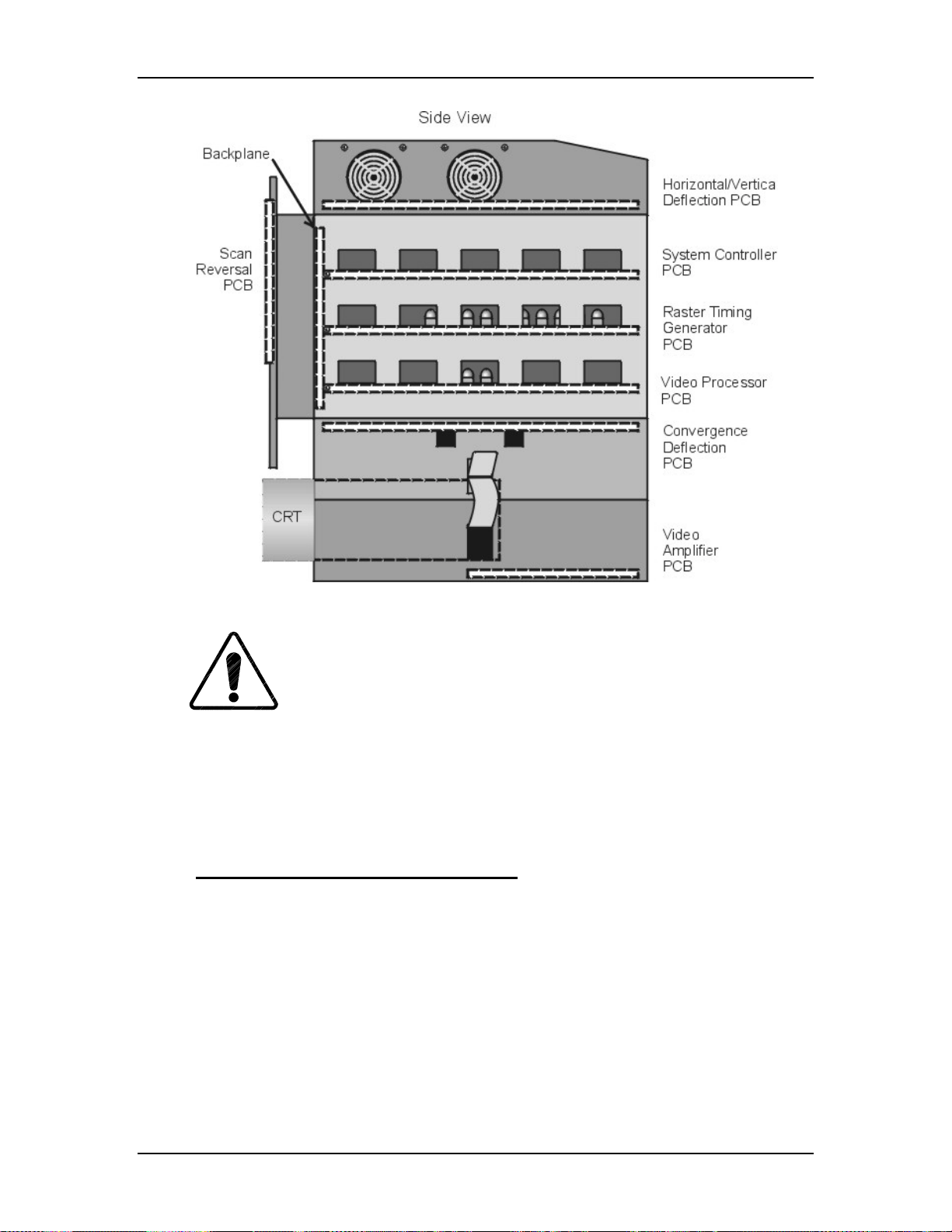
Chapter 5---Electronics
Figure 5-2
data be downloaded (
Model 250 Electronics Module with PCBs (side view).
CAUTION
It is very strongly recommended tha t setup
!
Exported, see section 8.2 Importing/Exporting
performing any of the following procedures. Exporting baseline source
setup data to disk is an excellent precautionary measure. It will save the
time of setting up new source file(s) in the case of an unexpected problem
5.3 System Controller PCB
System Controller PCB - Main Function
!
Enables control for the Low Voltage Power Supply, Arc Lamp and
cooling fans.
!
Fault monitors the HVPS, LVPS, Arc Lamp, and fans.
!
Provides IIC serial bus communication and control between PCBs.
!
Controls Zoom and Focus of the Projection Lens.
!
Generates Menu and Internal Patterns Overlays
) before
.
!
X and Y Convergence control
!
Threshold and Sensitivity for shading
Model 250 Service Manual 5-3
Page 59
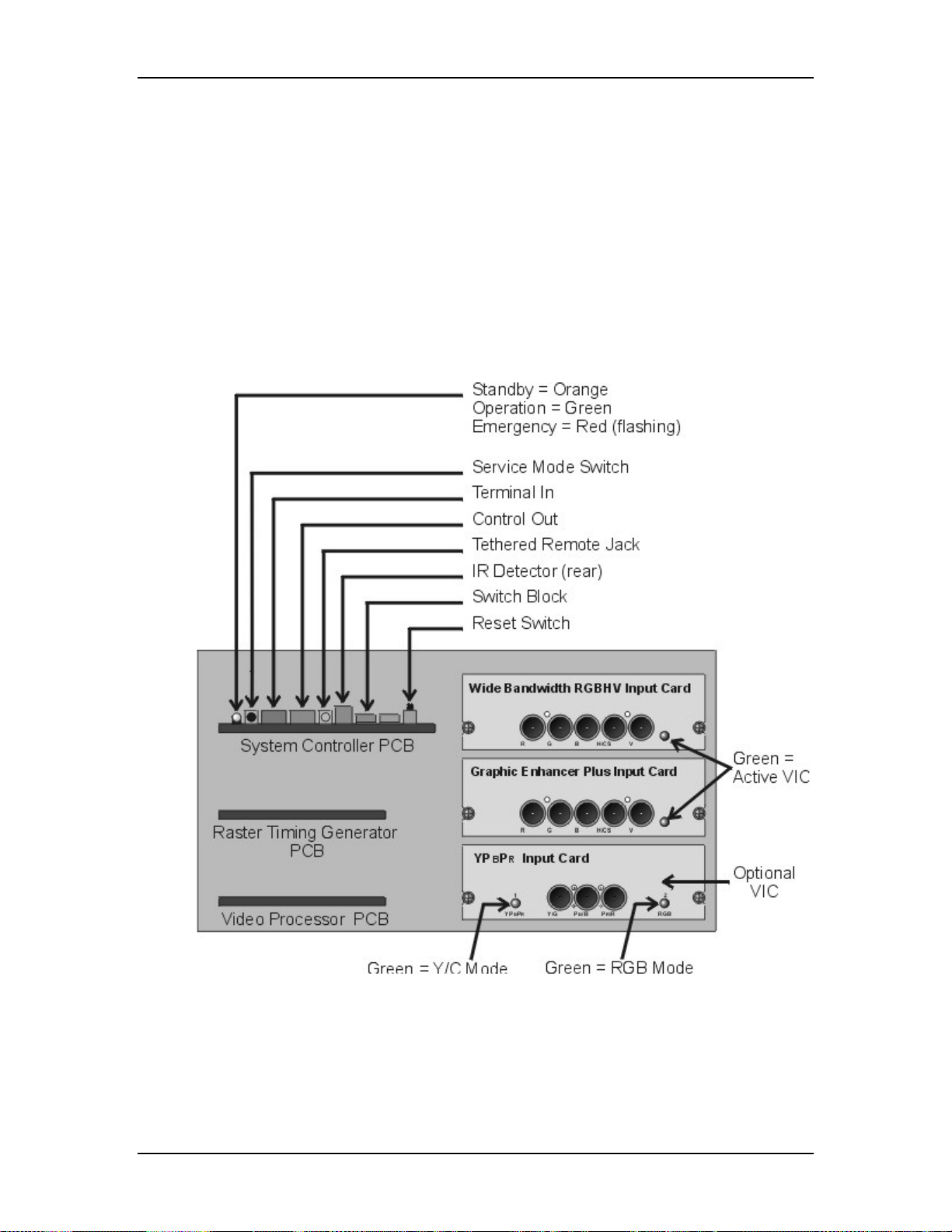
Chapter 5---Electronics
!
I/O control for VIC selection
!
Two RS-232 serial interface ports
!
Infrared (IR) remote control interface. Accepts input from front or rear IR
detectors.
!
External 3 color system status LEDs. Green indicates normal, yellow is
standby and red indicates a fault condition.
!
External Service Mode Switch. Pressing this switch during a power-up
sequence brings the system up in a diagnostic mode (for maintenance)
rather than a normal operating mode.
Figure 5-3
Rear of Electronics Module with rear cover and panel removed.
5-4 Model 250 Service Manual
Page 60

Chapter 5---Electronics
Figure 5-4
Model 250 Service Manual 5-5
System Controller PCB I/O Diagram for Power Supplies and peripherals.
Page 61

Chapter 5---Electronics
Figure 5-5
System Controller PCB I/O Diagram for other PCBs.
System Controller PCB - Inputs
/LV_OK - signal from the Low Voltage Power Supply; it tells the System
Controller PCB that all the non-standby supply voltages are working.
/HV_OK - signal from the High Voltage Power Supply; it tells the System
Controller PCB that all the high voltage supplies are working.
/LAMP_OK - signal from the Arc Lamp Power Supply.
/LAMP_LIT - signal from the Arc Lamp Power Supply; it tells the System
Controller PCB that the Arc Lamp is lit.
ODD_FIELD - Square wave signal from the Raster Timing Generator PCB, with
50% duty cycle that is low during odd fields of an Interlace signal. This signal is
high during noninterlaced signals.
5-6 Model 250 Service Manual
Page 62

Chapter 5---Electronics
280_CLK - Square wave signal from the Raster Timing Generator PCB, with
50% duty cycle, synchronized to the horizontal sync at 280 times the frequency of
the horizontal sync. This signal is used by the System Controller PCB to properly
output shading and convergence data.
SOURCE_VALID - Signal from Raster Timing Generator PCB indicates a new
source (or valid source). A high indicates a valid stable signal and a low indicates
a change in input signal.
H_DRIVE - Square wave signal from Raster Timing Generator PCB, with a 50%
duty cycle synchronized to the selected horizontal sync.
V_DRIVE - Square wave from Raster Timing Generator PCB, with a negative
going pulse synchronized to selected vertical sync with a pulse width of about
four horizontal lines.
/FRONT_IR - command signals from the front infrared receiver.
/REAR_IR - command signals from the rear infrared receiver
H_F2V - DC voltage from the Raster Timing Generator PCB, proportional to the
horizontal frequency of the current source.
IIC CLK - IIC clock line, unidirectional clock line for control of synchronous data
transfer of data between PCBs.
IIC DATA - IIC data line, bi-directional serial data line for control of
synchronous data transfer between the System Controller PCB and the Raster
Timing Generator PCB.
+5.1 V Stdby - from the Low Voltage Power Supply when the AC Circuit Breaker
is turned on; it supplies power to the CPU, Interlock Switches, and IR Detectors
before the projector receives the POWER ON command.
+5.1 V - from the Low Voltage Power Supply for all digital circuitry.
±15 V - from the Low Voltage Power Supply for all analog circuitry
GND - Ground
System Controller PCB - Outputs
/LV_ENA - signal to enable the Low Voltage Power Supply non-standby voltages
after the System Controller PCB receives the POWER ON command.
/FAN_ENA - signal to the Low Voltage Power Supply to turn on the +24 V stby
supply to turn on the cooling fans.
/LAMP_ENA - signal to enable the Arc Lamp Power Supply.
RGB_OVER - signal to Video Processor PCB for the On-screen Menu and /or
Internal Test Pattern for red, green, and blue.
OVERLAY - signal to the Video Processor PCB, to switch between internal and
external sources.
Model 250 Service Manual 5-7
Page 63

Chapter 5---Electronics
RGB_THRES - red, green, or blue Threshold correction information to the Video
Processor PCB.
RGB_SENS - red, green, or blue Sensitivity correction information to the Video
Processor PCB.
ISYNC - 5 MHz clock to the Raster Timing Generator PCB, used to generate the
internal sync signals
Y_RGB_CONV - control signals to Convergence Deflection PCB for Red, Green,
or Blue Convergence in the y-axis (full-scale correction is about 1 Vpp).
X_RGB_CONV - control signals to Convergence Deflection PCB for Red, Green,
or Blue Convergence in the x-axis (full-scale correction is about 1 Vpp).
CORR_SYNC - Square wave HCT level synchronous signal to the Convergence
Deflection PCB for the horizontal axis.
RGB_SHUT - Signal to operate the red, green, and blue shutters.
LENS_ZOOM - Signal to the zoom motor of the Projection Lens.
LENS_FOCUS - Signal to the focus motor of the Projector Lens.
System Controller PCB - Operation
Startup Functions
When AC Circuit Breaker is powered ON, the Low Voltage Power Supply sends
+5.1 V stdby voltage to the System Controller PCB. The +5.1 V Stdby powers the
CPU and IR Detector so the System Controller PCB can receive and respond to
the POWER ON command. The System Controller PCB sends a /FAN_ENA
signal back to the LVPS turning on the +24 V Stdby to turn the cooling fans on.
When the System Controller PCB receives a POWER ON command from either
the IR remote control or a PC, it sends the /LV_ENA signal to the Low Voltage
Power Supply. This turns on all the non-standby (±15 V, +5.1 V, +6.2 V, +24 V,
+80 V) voltages. After all the non-standby voltages power up, the LVPS sends the
/LV_OK signal back to the System Controller PCB to tell it that all the nonstandby voltages are present.
When the System Controller PCB receives a POWER ON command, it receives
the /LAMP_OK signal from the Arc Lamp Power Supply and sends the
/LAMP_ENA signal back to the Arc Lamp Power Supply to turn it on. The Arc
Lamp lights, and the Arc Lamp Power Supply sends a /LAMP_LIT signal back to
the System Controller PCB (see Figure 5-6).
The System Controller PCB also monitors the status of the High Voltage Power
Supply through the /HV_OK signal.
5-8 Model 250 Service Manual
Page 64
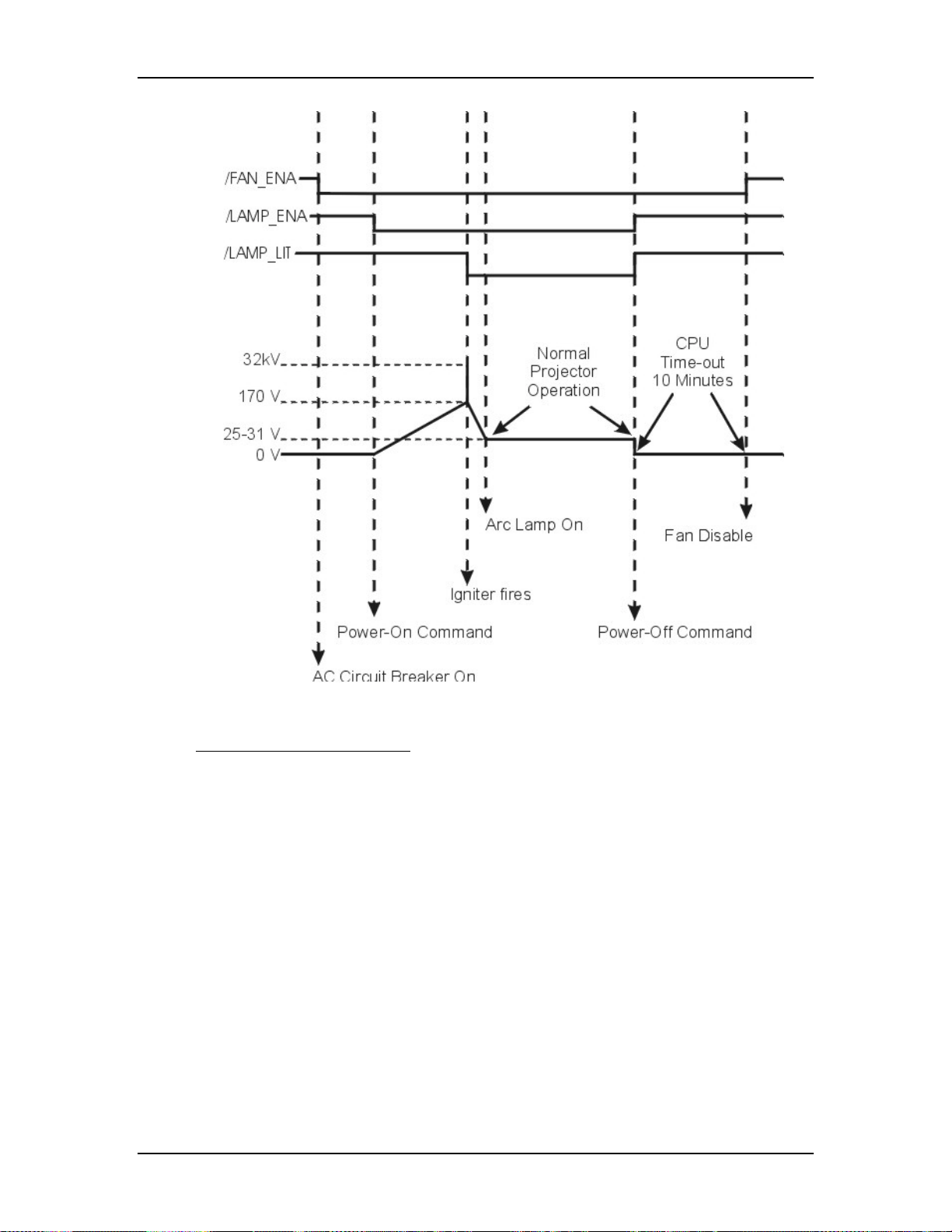
Chapter 5---Electronics
Figure 5-6
Power On timing sequence.
Normal Operation Functions
During normal projector operation, the System Controller PCB receives
commands through the remote control, tethered remote control, or a PC.
Commands issued from the IR remote controls are received through IR Detectors
located on the front and rear of the projector. Commands issued from a PC,
Laptop, or Tethered Remote Control are received through the RS-232 serial
interface ports.
The two RS-232 ports, labeled Terminal-in and Control-out, are functionally
almost identical. Both ports can be used to interface with computers, switchers, or
other remote controlling devices using a null modem cable. The difference is,
importing and exporting of configuration data can only be performed through the
Terminal-in. The dipswitch on the back of the System Controller PCB controls
the baud rate (see Figure 7-2).
The System Controller PCB enables the Video Processor PCB to select between
an internal and external source through the OVERLAY signal. The System
Model 250 Service Manual 5-9
Page 65

Chapter 5---Electronics
Controller PCB also enables the selected VICs through the IIC bus based on the
VIC selected on the Channel Menu.
The System Controller PCB generates the on-screen menus and test pattern
overlays and sends them to the Video Processor PCB. It sends the X and Y
Convergence correction data to the Convergence Deflection PCB. It sends
Threshold and Sensitivity shading data to the Video Processor PCB for the all
three colors. The System Controller PCB stores all the configuration data such as
Geometry, Convergence, Shading, ILA® Bias and Sensitivity, and G2 settings etc.
in flash memory and allows that data to be exported to, or imported from a floppy
disk.
The System Controller PCB displays system status through a single three-color
LED visible on the back panel. A green light indicates normal operation, the
yellow indicates standby operation, and red indicates a fault or error condition.
The System Controller PCB has an External Service Mode Switch that enables the
operator to switch from the normal operating mode to a diagnostic mode. If there
is a new release of system software, it can be uploaded into the projector by
switching into the diagnostic mode. The procedure for this is in the Software and
Protocol section (see Chapter 8, Software and Protocol).
System Controller PCB - Remove and Replace
Tools Needed
#1 Pozi-drive Phillips-head screwdriver
#0 Pozi-drive Phillips-head screwdriver
Parts Needed
System Controller PCB - p/n 104678
To remove the System Controller PCB:
1.
Power OFF the projector by IR Remote or PC, and allow the cooling fans
to run until they shut off automatically.
2.
Turn the AC Circuit Breaker to the OFF position and unplug the AC
Power Cord.
3.
Disconnect all the external source video cables and control cables.
4.
Remove the rear cover.
5.
Remove the Back Panel. Remove the nine Pozi-drive Phillips-head
retaining screws using the #1 Pozi-drive Phillips screwdriver.
6.
Remove the Connector Bracket by removing the single Pozi-drive
Flathead Phillips-head screw using the #0 Pozi-drive Phillips screwdriver.
7.
Pull the black Card Extractor handles back to disconnect the System
Controller PCB connector and pull the PCB out of the Electronics Module.
8.
Reverse the procedure to install the System Controller PCB.
5-10 Model 250 Service Manual
Page 66

5.4 Video Processor PCB
Video Processor PCB - Main Functions
!
Video signal input and multiplexing
!
Sync signal stripping
!
Overlay signal multiplexing
!
Brightness, Contrast, DC Restore and Blanking
!
Video signal gamma correction
!
Sensitivity and Threshold signal input and control
!
Automatic Contrast, G2, and internal image limiting
Video Processor PCB - Inputs
RGBHV VIC 1,2, & 3 - External image signals from the VICs for red, green, and
blue.
/SEL_VIC - input signal from the RGB VIC used to select the input source from
VIC #1.
Chapter 5---Electronics
RGB_OVER - from the System Controller PCB, the Menu overlays and internal
test patterns for red, green, and blue.
OVERLAY - from the System Controller PCB, switches between internal and
external sources.
CLAMP - Pulse signal from the Raster Timing Generator PCB, tells the Video
Processor PCB the timing and duration of the DC Restore.
BLANKING - Pulse signal from the Raster Timing Generator PCB, it tells the
Video Processor PCB the blanking interval during the scan.
RGB_THRESH - Threshold correction information for red, green, or blue from
the System Controller PCB. Real time data at 0-1 V.
RGB_SENS - Sensitivity correction information for red, green or blue from the
System Controller PCB. Real time data at 0-1 V.
RGB_BEAM - sense signal proportional to the cathode current averaged over
several horizontal lines in the red, green, or blue CRT. The voltage level is +
mV/mA.
/VA_OK - signal from the Video Amplifier PCB telling the Video Processor PCB
the Video Amplifier PCB is receiving red, green, and blue deflections voltages
from the Horizontal Vertical Deflection PCB.
IIC_DATA - IIC data line. Bi-directional serial line for synchronous data transfer
between the System Controller PCB and Video Processor PCB.
IIC_CLK - IIC clock line. Unidirectional clock line for control of synchronous
data transfer over IIC bus.
Model 250 Service Manual 5-11
Page 67
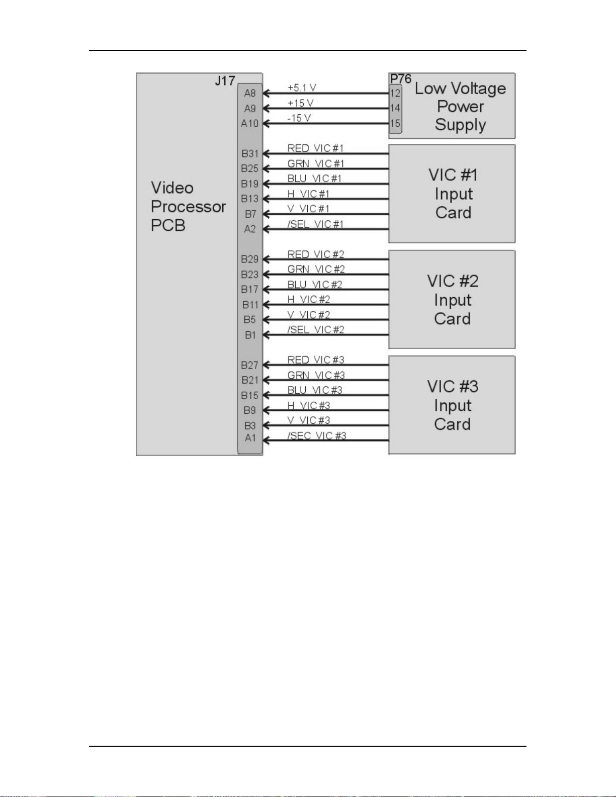
Chapter 5---Electronics
Figure 5-7
5-12 Model 250 Service Manual
Video Processor PCB I/O diagram for VICs and Power Supplies.
Page 68

Chapter 5---Electronics
Figure 5-8
Video Processor PCB I/O diagram for PCBs.
Video Processor PCB - Outputs
RGB_VID - red, green, or blue video signal to Video Amplifier PCB, typically 01 V.
H&V_SYNC - horizontal sync pulse goes to the Raster Timing Generator PCB.
GRN_SYNC - sync-on-green sync pulse goes to the Raster Timing Generator
PCB.
RESTORE - DC Restore control signal to the Video Amplifier PCB. This signal
controls the DC level of the image signal, clamping it to the proper level on the
Video Amplifier PCB.
Model 250 Service Manual 5-13
Page 69

Chapter 5---Electronics
RGB_G2 - red, green, or blue G2 voltage adjust control signal to the Video
Amplifier PCB.
G1_BIAS - G1 adjust control voltage (global adjustment) to the Video Amplifier
PCB.
IIC_INT - IIC interrupt output to System Controller PCB.
Video Processor PCB - Operation
The Video Processor PCB accepts image and synchronizing inputs in either
composite or separate RGBHV component format from the selected VIC. When
the projector receives the power ON command, the System Controller PCB polls
the VICs to determine what VICs are available. It then activates the VIC selected
in the Channel Menu (see section 4-6 in the User’s Guide). The selected VIC
sends a signal (/SEL_VIC) to the Video Processor PCB telling it which VIC is
active.
The Video Processor separates the sync pulses and passes them (H_SYNC and
V_SYNC) on to the Raster Timing Generator PCB. If the source sync type is
Sync-on-Green, the Video Processor strips the horizontal and vertical syncs from
the green input and sends that sync signal (G_SYNC) to the Raster Timing
Generator PCB.
The Video Processor PCB adjusts the image input information with contrast,
brightness, DC restore clamp, and blanking. Contrast changes the peak to peak
amplitude of the External image while keeping the offset (black level) the same.
Brightness shifts the DC level of the External image up or down while keeping
the peak to peak amplitude the same. The DC restore circuit (or clamp pulse)
restores the DC offset (black level) after each horizontal line. Contrast and
Brightness commands come from the IIC data bus. The DC Restore and Blanking
signals come directly from the Raster Timing Generator PCB.
The Video Processor PCB switches in the menu overlays and internal test
patterns. It performs gamma correction adjustments, and applies the shading
(sensitivity and threshold) adjustments. The menu overlay signals create the
displayed menus and test patterns. Menu overlays are generated on the System
Controller PCB. The gamma circuit corrects non-linearities, primarily due to the
®
. Gamma correction consists of degrees of black and white boost. The
ILA
gamma tracking controls adjust the gain of the image information near the 50%
level.
Sensitivity and Threshold are shading adjustments that correct for non-uniformity
in the CRT and ILA
®
. Sensitivity adjusts the gain (same as Contrast only local
instead of global) and threshold adjusts the DC offset (black level) (same as
Brightness, only local instead of global) to adjust the dark areas of the red, green,
or blue channel. The sensitivity and threshold commands come from the System
Controller PCB through the IIC bus and adjust both the internal and external
image information. Sensitivity and Threshold are applied to the image
information after the contrast, brightness and gamma correction.
5-14 Model 250 Service Manual
Page 70

Chapter 5---Electronics
The G2 voltage accelerates the electrons that are emitted from the cathode of the
CRT. The CRT filament emits the electrons and G1 voltage regulates the amount
of electrons that are emitted from the cathode. The G2 voltage is adjusted through
the menu (Black Level). The Video Processor PCB receives the G2 control data
for each color through the IIC bus and sends an analog voltage to the Video
Amplifier PCB to control the G2 voltage.
The Video Processor PCB protects the CRTs from excess beam currents to
prevent it from burning the phosphor. The Video Amplifier PCB sends a sample
of the beam current (RGB_BEAM) for each CRT back to the Video Processor
PCB. The Video Processor PCB compares this sample to a preset value. If the
sample beam current is higher than the preset value, the Video Processor PCB
reduces the contrast for the CRT with high beam current. If the CRT beam current
is still high, it then reduces the G2 voltage. The maximum beam current is 250 µA
per CRT.
The Video Processor PCB receives the G1_BIAS signal from the System
Controller PCB through the IIC bus and sends a voltage to the Video Amplifier
PCB to set the brightness level.
Figure 5-9
Video Processor PCB LEDs.
Video Processor PCB - Remove and Replace
Tools Needed
#1 Pozi-drive Phillips-head screwdriver
Parts Needed
Video Processor PCB - p/n 105234
To remove the System Controller PCB:
1. Power off the projector by IR Remote or PC, and allow the cooling fans to
run until they shut off automatically.
2. Turn the AC Circuit Breaker to the OFF position and unplug the AC
Power Cord.
3. Disconnect all the external source video cables and control cables.
4. Remove the rear cover.
5. Remove the Back Panel by removing the nine Pozi-drive Phillips-head
retaining screws using the #1 Pozi-drive Phillips screwdriver.
Model 250 Service Manual 5-15
Page 71

Chapter 5---Electronics
6. Pull the black card extractor handles back to disconnect the Video
Processor PCB connector and pull the PCB out of the Electronics Module.
7. Reverse the procedure to install the Video Processor PCB.
5.5 Raster Timing Generator PCB
Raster Timing Generator PCB - Main Functions
!
Generates an internal sync pulse
!
Detects and selects sync pulses
!
Generates a phase locked sync
!
Generates blanking pulse
!
Provides horizontal and vertical phase adjustments
!
Detects interlaced and generates odd field pulse
!
Selects horizontal frequency band
!
Generates horizontal line count and vertical count
!
Provides IIC interface
!
Generates clamp pulse
!
Detects changes in source
!
Generates HVPS_SYNC signal
!
Enables horizontal deflection (/H_ENA) circuitry
Figure 5-10
Raster Timing Generator I/O diagram for Power Supplies.
5-16 Model 250 Service Manual
Page 72
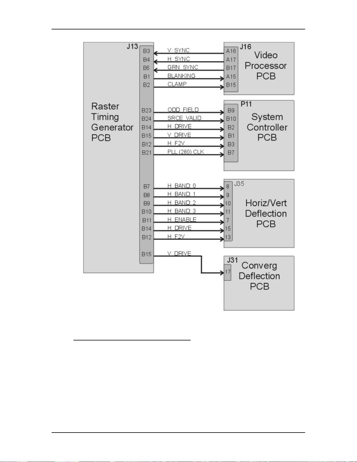
Chapter 5---Electronics
Figure 5-11
Raster Timing Generator for other PCBs.
Raster Timing Generator PCB - Inputs
V_SYNC - input vertical sync from the Video Processor PCB.
H_SYNC - input horizontal sync from the Video Processor PCB.
G_SYNC - Sync-on-Green sync stripped from green video signal at the Video
Processor PCB.
ISYNC - 5 MHz clock from the System Controller PCB used to generate the
internal sync.
Model 250 Service Manual 5-17
Page 73

Chapter 5---Electronics
IIC_CLK - IIC clock line. Unidirectional clock line for control of synchronous
data transfer over the IIC bus.
IIC_DATA - IIC data line. Bi-directional serial line for synchronous data transfer
between System Controller PCB and Raster Timing Generator PCB.
+15 V (two inputs) - input power from LVPS for analog circuitry including the
Phase Lock Loop (PLL) circuit.
-15 V (two inputs) - input power from LVPS for analog circuitry including the
Phase Lock Loop (PLL) circuit.
+5.1 V - input power from the LVPS for digital circuitry
Raster Timing Generator PCB - Outputs
SOURCE_VALID - signal to the System Controller PCB, indicates a new or valid
source. High = valid, stable source, low = change in input source.
ODD_FIELD - square wave to System Controller PCB, with 50% duty cycle that
is high during the odd field of an interlaced signal and low for non-interlaced
signals.
280_CLK - square wave to System Controller PCB, with 50% duty cycle,
synchronized to the horizontal sync at 280 times the frequency of the horizontal
sync. This signal is used by the System Controller PCB to properly output shading
and convergence data.
CLAMP - a negative-going image clamp signal to the Video Processor PCB, with
about 3% duty cycle.
BLANKING - right, left, top, and bottom blanking signal to the Video Processor
PCB.
H_BAND(0-3) - horizontal frequency band lines to the Horizontal Vertical
Deflection PCB.
Band 0 = 15 - 24 kHz
Band 1 = 24 - 28 kHz
Band 2 = 28 - 55 kHz
Band 3 = 56 - 90 kHz
/H_ENA - enables the horizontal deflection amplifier on the Horizontal Vertical
Deflection PCB, Low = enabled deflection; high = disabled deflection.
H_FV2 - a DC voltage to the Horizontal Vertical Deflection PCB and System
Controller PCB, proportional to horizontal frequency.
H_DRIVE - square wave to the Horizontal Vertical Deflection PCB, 50% duty
cycle synchronized to the selected horizontal sync. This signal provides a sample
of the horizontal sync to the horizontal amplifier on the Horizontal Vertical
Deflection PCB.
HVPS_SYNC - synchronization pulse for High Voltage Power Supply,
synchronized with the selected horizontal sync at the same, half, or one third the
frequency.
5-18 Model 250 Service Manual
Page 74

Chapter 5---Electronics
V_DRIVE - square wave negative going pulse to the Convergence Deflection
PCB, synchronized to the selected vertical sync with the pulse width of about four
horizontal periods.
Raster Timing Generator PCB - Operation
The Raster Timing Generator PCB generates a square wave that is phase-locked
to the horizontal sync pulse. It generates timing signals such as Blanking that goes
to the Video Processor PCB and Video Amplifier PCB, and the H_DRIVE signal
that goes to the Horizontal Vertical Deflection PCB. The PLL (Phase Locked
Loop) locks these signals to the horizontal sync signal. The Raster Timing
Generator PCB has LEDs that indicate the type of sync pulse received and the
status of the PLL circuit (see Figure 5-12).
The H_DRIVE signal supplies a sample of the horizontal scan frequency to the
horizontal deflection amplifier on the Horizontal Vertical Deflection PCB for
timing of the horizontal deflection waveform.
The Raster Timing Generator PCB checks the incoming syncs to make sure they
are valid signals and within the frequency ranges (15 - 90 kHz - horizontal, and 45
- 120 Hz vertical). If the syncs are out of range, or there is no sync pulse, the
Raster Timing Generator PCB generates an internal interlaced sync at 33.7 kHz
horizontal and 60 Hz vertical.
The Raster Timing Generator PCB tells the System Controller PCB when there
has been a source change using the SOURCE_VALID signal.
The Raster Timing Generator PCB generates the Blanking signal, and the
horizontal Phase signal.
!
Blanking shuts off the image during times where there is no active video. The
Blanking signal pulls the G1 voltage on the Video Amplifier PCB down far
enough to make the CRT shut off. The Raster Timing Generator PCB receives
the top, bottom, left, or right blanking command on the IIC bus and sends the
appropriate Blanking signal to the Video Processor PCB. The Raster Timing
Generator PCB receives the Blanking adjustment commands on the IIC bus.
!
The horizontal Phase signal adjusts the on-screen image horizontally to
compensate for different phase requirements at different horizontal scan
frequencies. The Raster Timing Generator PCB receives this command from
the System Controller PCB on the IIC bus.
The Raster Timing Generator PCB sends several signals such as 280_CLOCK
signal to the System Controller PCB to correctly set the timing for shading and
convergence data.
In order to combat noise caused by crosstalk between supplies (beat patterns) the
High Voltage Power Supply is phase locked to the incoming horizontal frequency
by the HVPS_SYNC signal.
The horizontal flyback time gets shorter as the horizontal scan frequency
increases. The Raster Timing Generator PCB works together with the Horizontal
Model 250 Service Manual 5-19
Page 75
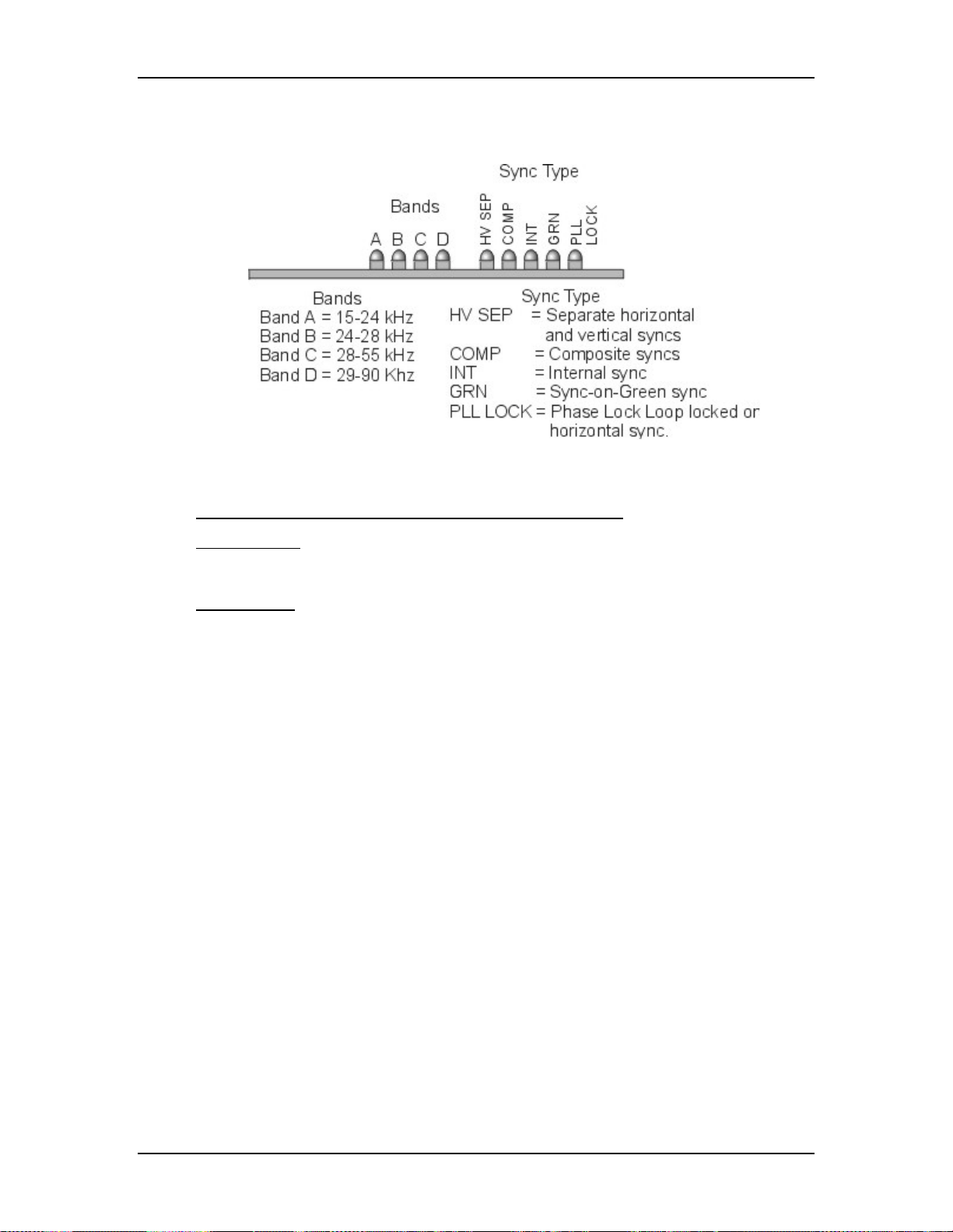
Chapter 5---Electronics
Vertical Deflection PCB to break the range of horizontal scan frequencies into
four smaller ranges called bands (see Figure 5-12).
Figure 5-12
LEDs on the Raster Timing Generator PCB.
Raster Timing Generator PCB - Remove and Replace
Tools Needed
#1 Pozi-drive Phillips-head screwdriver
Parts Needed
Raster Timing Generator PCB - p/n 105238
To remove the Raster Timing Generator PCB:
1.
Power OFF the projector by IR Remote or PC, and allow the cooling fans
to run until they shut off automatically.
2.
Turn the AC Circuit Breaker to the OFF position and unplug the AC
Power Cord.
3.
Disconnect all the external source video cables and control cables.
4.
Remove the rear cover.
5.
Remove the Back Panel. Remove the nine Pozi-drive Phillips-head
retaining screws using the #1 Pozi-drive Phillips screwdriver.
6.
Pull the black Card Extractor handles back to disconnect the Raster
Timing Generator PCB connector and pull the PCB out of the Electronics
Module.
7.
Reverse the procedure to install the Raster Timing Generator PCB.
5-20 Model 250 Service Manual
Page 76

5.6 Horizontal Vertical Deflection PCB
Horizontal Vertical Deflection PCB - Main Functions
!
Drive the main horizontal deflection coils to provide horizontal raster scan
for the CRTs
!
Drive main vertical coils to provide vertical raster scan for the CRTs
!
Horizontal raster centering for all three colors
!
Switch mode power supply generating the required proportional DC
supply
!
Horizontal width adjustment
!
Horizontal retrace switch network
!
Left/right pincushion and keystone correction
!
Vertical linearity adjustments individually for all three colors.
!
Vertical raster centering for all three colors
!
IIC interface.
Chapter 5---Electronics
Horizontal Vertical Deflection PCB - Inputs
H_BAND:0-3 - horizontal scan frequency bands, from Raster Timing Generator
PCB.
/H_ENABLE - from the Raster Timing Generator PCB, enables the horizontal
deflection supply. Low = enabled deflection, High = disabled deflection.
H_DRIVE - square wave from the Raster Timing Generator PCB, 50% duty cycle
synchronized to the selected horizontal sync.
H_F2V - a DC voltage from the Raster Timing Generator PCB, proportional to
horizontal frequency
H_LOCK (neg.) - Deflection Yoke Connector Interlock return from the Scan
Reversal PCB.
DEFL_OK - deflection status signal from the Scan Reversal PCB (high = good,
(about 2 V), low = no scan).
V_RAMP - vertical ramp waveform from the Convergence Deflection PCB,
(about 4 Vpp).
V_PARAB - vertical parabola waveform from the Convergence Deflection PCB,
(about 4 Vpp).
FRONT/REAR - front or rear projection status line from the Scan Reversal PCB.
(FRONT = low, REAR = high).
FLOOR/CEILING - floor or ceiling projection status line from the Scan Reversal
PCB. (FLOOR = low, CEILING = high).
Model 250 Service Manual 5-21
Page 77

Chapter 5---Electronics
IIC_CLK - IIC clock line
IIC_DATA - IIC data line
IIC_SINT - IIC interrupt
±15 V - input power from the Low Voltage Power Supply, for the analog
circuitry.
+5.1 V - input power from the Low Voltage Power Supply, for the digital
circuitry.
Figure 5-13
5-22 Model 250 Service Manual
Horizontal/Vertical I/O Diagram.
Page 78

Chapter 5---Electronics
Figure 5-14
Horizontal/Vertical I/O Diagram for Scan Reversal and Video
Amplifier PCBs.
Model 250 Service Manual 5-23
Page 79

Chapter 5---Electronics
Vertical Adjustment Pots
Figure 5-15
Physical layout of the Horizontal/Vertical PCB (note the Vertical Size
Adjustment Pots (Red-137, Grn-148, and Blu-160) on the lower right).
Horizontal Vertical Deflection PCB - Outputs
/SWEEP_OK - signal to the Video Amplifier PCB, derived from the H_ENA
signal from the Raster Timing Generator PCB, and the DEFL_OK from the Scan
Reversal PCB.
WIDTH_CTRL - a DC voltage to the Convergence Deflection PCB that adjusts
the parabola waveforms used for geometric correction (about 4 V max.).
H_RGB(pos.) - horizontal deflection waveform return from the Scan Reversal
PCB. A DC offset that shifts the reference for red, green, and blue image for
centering.
H_OUT_FLYB - output waveform to the Scan Reversal PCB for the horizontal
deflection coils on the CRTs.
H_LOCK (pos.) - +15 V to the Scan Reversal PCB for deflection yoke connector
interlock.
V_RGB (pos.) - positive vertical deflection voltage to the Scan Reversal PCB.
V_RGB (neg.) - negative vertical deflection voltage to Scan Reversal PCB.
±15 V - pass through voltage from Low Voltage Power Supply to Scan Reversal
PCB to power analog circuitry.
+5.1 V - pass through voltage from Low Voltage Power Supply to Scan Reversal
PCB to power digital circuitry.
H_CUR_FDBK - current feedback to horizontal waveform amplifier.
5-24 Model 250 Service Manual
Page 80

Chapter 5---Electronics
Horizontal Vertical Deflection PCB - Operation
The Horizontal Vertical Deflection PCB consists of a RGB horizontal deflection
amplifier and separate vertical deflection amplifiers.
The Horizontal Deflection Amplifier
The horizontal deflection amplifier is a switching mode power supply that varies
according to the input horizontal sync frequency. The horizontal supply generates
the sawtooth current-driven waveform that drives the horizontal deflection coils
on the CRT. The sawtooth current waveform creates the raster on the CRT. The
horizontal amplifier also generates the retrace waveform portion of the raster.
The horizontal deflection sawtooth waveform is modulated by other waveforms
that perform geometric correction such as Pincushion, Keystone, Horizontal
Centering, Horizontal Linearity and Horizontal Width adjustment. The Width
Control voltage also goes to the Convergence Deflection PCB to adjust the
geometric correction parabolas.
The H_F2V signal converts the input horizontal scan frequency to a voltage that
switches from one band (see explanation of bands in the Raster Timing Generator
PCB Operation section) to the next depending on the horizontal scan frequency.
This adjusts the retrace time to correspond to the input horizontal frequency. The
output of the horizontal supply is H_OUT_SUPPLY that goes on to the Scan
Reversal PCB.
CRT Protection
The Horizontal Vertical Deflection PCB uses the H_LOCK+, H_LOCK- and
DEFL_OK signal to protect the CRTs from being damaged if the deflection
waveforms are lost. Refer to the CRT Protection section in Chapter 9 for a
complete discussion of these and all the signals associated with CRT Protection.
The Horizontal Vertical Deflection PCB receives the DEFL_OK signal from the
Scan Reversal PCB indicating the presence of the horizontal and vertical
deflection waveforms. If there is a failure of any of the Deflection Yokes
(horizontal or vertical), a current sense line on the Scan Reversal PCB forces
DEFL_OK low. On the Horizontal Vertical Deflection PCB, the DEFL_OK
signal becomes /SWEEP_OK and is sent to the Video Amplifier PCB where it
shuts down G
. If DEFL_Ok is forced low, or if /H_ENA is forced high,
1
/SWEEP_OK goes high. The /SWEEP_OK goes to the Video Amplifier PCB. If it
goes high, it shuts down the G
voltages and G2 Regulator circuit (see
1
Troubleshooting, CRT Protection section).
Vertical Deflection Amplifier
The vertical deflection sawtooth waveform is generated on the Convergence
Deflection PCB and timed to the vertical sync by the V_DRIVE signal from the
Raster Timing Generator PCB. The Convergence Deflection PCB sends this
waveform along with a parabola waveform V_PARAB to the vertical deflection
amplifier on the Horizontal Vertical Deflection PCB. The Horizontal Vertical
Deflection PCB takes V_RAMP, amplifies it and adds geometric correction with
Model 250 Service Manual 5-25
Page 81
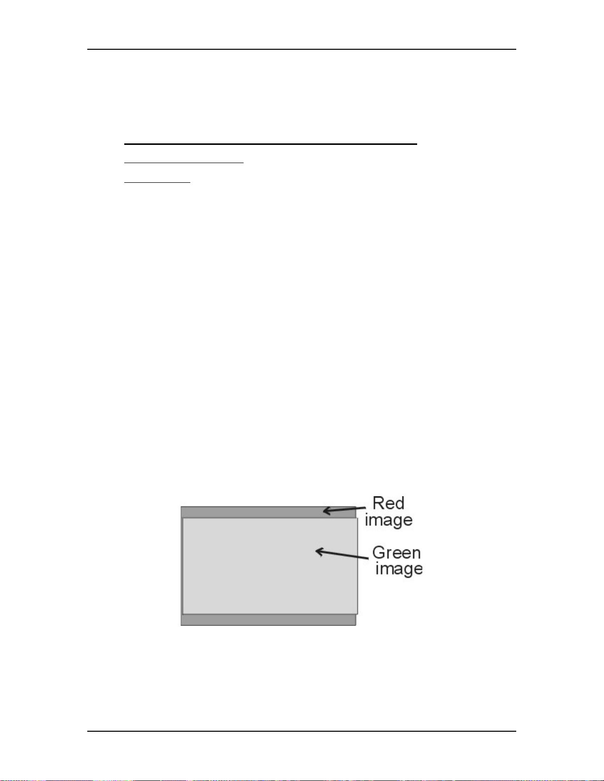
Chapter 5---Electronics
the V_PARAB waveform. The output waveform V_RGB+ goes to the Scan
Reversal PCB and then drives the Vertical Deflection Yokes. The Vertical
Deflection Yoke return signal to the Horizontal Vertical Deflection PCB is
V_RGB-.
Horizontal Vertical Deflection PCB - Service Adjustments
Vertical Size Adjustment
Tools Needed
Miniature Potentiometer-Trimmer Adjustment tool
To adjust the Vertical height (see Figure 5-15):
1. Remove the rear cover and pull the Interlock switch out to the Service
Mode position.
2. Power ON the projector by IR Remote or PC, and allow it to stabilize for a
minimum of 15 minutes
3. Use the X-hatch test pattern.
NOTE:
The green image is the reference to which the red image and blue
image will be matched. The green height pot should not need adjustment
except when the green CRT has been replaced.
4. Hide Blue and view Red and Green.
5. If Red is higher than Green at the top and lower than Green at the bottom
of the X-hatch image, or If lower than Green at the top and higher at the
bottom, adjust Red vertical pot (R137) to correct the error.
Vertical Adjustment Potentiometers (see Figure 5-15)
Red - R137
Green - R148
Blue - R160
Figure 5-16
5-26 Model 250 Service Manual
Red image needs vertical adjustment (decrease).
Page 82

Chapter 5---Electronics
Figure 5-17
Red image needs vertical adjustment (increase).
If Red is higher than Green at the top and bottom, or lower than Green at
the top and bottom, the Red image may not being centered correctly. This
can be corrected with the centering adjustment (see Model 250 User’s
Guide, Chapter 5).
Figure 5-18
Red image needs vertical centering.
If the Red height pot does not completely eliminate the difference in
height between Red and Green, balance the difference at the top and
bottom. Too much of an difference at the top or bottom makes
convergence procedures harder to accomplish.
4. Repeat Steps 2 and 3 above for Blue while hiding Red.
5. Recheck all Geometry and Convergence settings (see User’s Guide) and
readjust wherever necessary.
Model 250 Service Manual 5-27
Page 83

Chapter 5---Electronics
Horizontal Vertical Deflection PCB - Remove and Replace
The Horizontal/Vertical (H/V) Deflection PCB is located in the upper portion of
the Electronic Module card cage.
Tools Needed:
#1 Pozi-drive Phillips-head screwdriver
Parts Needed:
Horizontal Vertical Deflection PCB p/n 105236
To remove the Horizontal/Vertical (H/V) Deflection PCB:
1. Power off the projector by IR Remote or PC, and allow the cooling fans to
run until they shut off automatically.
2. Turn the AC Circuit Breaker to the OFF position and unplug the AC
Power Cord.
3. Remove the rear cover.
4. Disconnect six connectors; J34, J35, J36, J41, J42, and J43 (see Figure
5-15). Move the cables out of the way.
5. Loosen (it is not necessary to remove) the 5 Pozi-drive Phillips-head
screws that secure the Horizontal Vertical Deflection PCB to the
electronic module cage.
6. Remove the Horizontal Vertical Deflection PCB by sliding it toward the
left side of the projector (this is the upward direction if the electronic
module is tilted up) so that the mounting screws clear the access holes.
Then lift the side of the PCB that is nearest the front of the projector first
and angle it upward so that the side closest to the rear clears the lip of the
electronic module frame. Be careful when removing or reinstalling the
PCB to avoid damaging it on the fan screws or cable clamps.
7. Reinstall the Horizontal Vertical Deflection PCB by lowering the side that
is nearest to the rear of the projector in first until it clears the electronic
module edge, then lowering the other side. Carefully fit the board over the
mounting screws and slide the board into position. Tighten the screws and
reconnect the connectors.
5.7 Convergence Deflection PCB
Convergence Deflection PCB - Main Functions
!
Generation of various waveforms for the horizontal and vertical
deflection.
!
Height control
!
Generation of waveforms for dynamic focus
!
Various geometry correction functions for the horizontal and vertical axes
5-28 Model 250 Service Manual
Page 84

Chapter 5---Electronics
!
Convergence output amplifiers for all colors and both horizontal and
vertical axes
!
Convergence enable and raster fill function
!
ILA® assembly driver circuitry with temperature compensation
!
Phase locked loop for ILA® assembly drivers
!
IIC serial bus interface
Convergence Deflection PCB - Inputs
X_RGB_CONV - x-axis Convergence waveform from the System Controller
PCB (the amplitude for full-scale correction is about 1 Vpp).
Y_RGB_CONV - y-axis Convergence waveform from the System Controller
PCB (the amplitude for full-scale correction is about 1 Vpp).
CORR_SYNC - square wave from the System Controller PCB, logic level
synchronization signal for the horizontal axis.
V_DRIVE - square wave from the Raster Timing Generator PCB, logic level
synchronized to vertical sync with four horizontal line duty cycle.
WIDTH_CONTROL - a DC waveform from the Horizontal Vertical Deflection
PCB that controls the image width.
IIC_CLK - IIC clock line.
IIC_DATA - IIC data line.
IIC_SINT - IIC interrupt line.
±15 V - input power from the Low Voltage Power Supply for the analog circuitry.
+5.1 V- input power from the Low Voltage Power Supply for the digital circuitry.
Convergence Deflection PCB - Outputs
RGB_ILA®(pos) - positive outputs to the ILA® for the red, green, and blue ILA
®
driver circuitry (about ±12 Vpp).
RGB_ILA®(neg) - negative outputs to the ILA® for the red, green, and blue ILA
®
driver circuitry (about ±12 Vpp).
H_PARABOLA - horizontal parabola for dynamic focus section of the High
Voltage Power Supply.
V_PARABOLA - vertical parabola for dynamic focus section of the High Voltage
Power Supply.
V_RAMP - vertical ramp waveform to the Horizontal Vertical Deflection PCB
(about 4 Vpp).
V_PARABOLA - vertical parabola waveform to the Horizontal Vertical
Deflection PCB (about 4 Vpp).
Model 250 Service Manual 5-29
Page 85

Chapter 5---Electronics
Figure 5-19
5-30 Model 250 Service Manual
Convergence Deflection PCB I/O Diagram.
Page 86
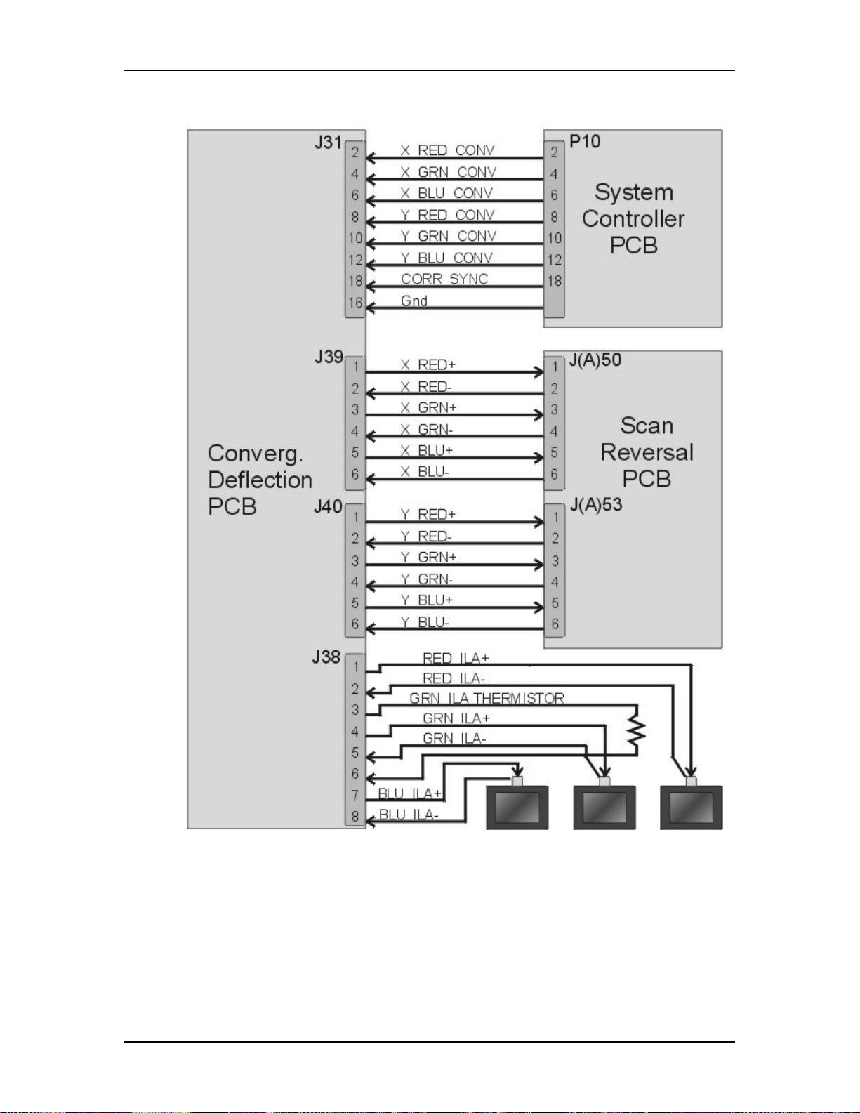
Chapter 5---Electronics
Figure 5-20
Model 250 Service Manual 5-31
Convergence Deflection PCB I/O Diagram.
Page 87

Chapter 5---Electronics
Figure 5-21
Physical layout of the Convergence/Deflection PCB.
Convergence Deflection PCB - Operation
The Convergence Deflection PCB performs four main functions. It generates the
vertical deflection sawtooth waveform. It generates the square waves that bias the
three ILA®s. It controls the amplitude of waveforms used for convergence
corrections, and it generates the parabolic waveform used for dynamic focus.
The Convergence Deflection PCB receives the V_DRIVE signal, which is a
sample of the vertical sync, from the Raster Timing Generator PCB. The
Convergence Deflection PCB has a Waveform Generator Section that generates
the vertical deflection sawtooth waveform and outputs the V_RAMP signal that
drives the vertical amplifier on the Horizontal Vertical Deflection PCB. The
vertical amplifier drives the CRT deflection coils for vertical deflection. The
Waveform Generator also generates the parabolic waveforms used for geometry
correction such as bow, pincushion, keystone, and linearity
Each of the ILA®s is biased by a square wave generated by the Waveform
Generator on the Convergence Deflection PCB. Each ILA® is biased separately
®
through the ILA
Bias command in the Factory Adj. Menu. The commands are
received through the IIC interface. As the square wave that drives the ILA® is
increased, the ILA® becomes more sensitive to the image light that strikes the
photoconductive layer and outputs more light. The command that controls the
frequency of the ILA
global command for all the ILA
Attached to the green ILA
®
the ILA
ILA
. It sends the Convergence Deflection PCB a signal that adjusts the green
®
bias to compensate for temperature variations inside the projector. If the
®
bias square wave is referred to as ILA® Sensitivity. It is a
®
s and is received from the IIC interface.
®
mount is a thermistor that senses the temperature of
5-32 Model 250 Service Manual
Page 88

Chapter 5---Electronics
temperature of the green ILA® increases, the bias is increased to maintain a
constant ILA® output.
The Convergence Deflection PCB receives commands for x and y-axis
convergence from the System Controller PCB. The Convergence Deflection PCB
has a Convergence Control Section that receives the convergence commands,
waveforms from the Waveform generator, and geometric correction data from the
IIC interface. It amplifies the convergence data and outputs it to the Scan Reversal
PCB.
The Waveform Generator section generates a horizontal and vertical parabolic
waveforms that the High Voltage Power Supply uses for dynamic focus.
Convergence Deflection PCB - Remove and Replace
The Convergence/Deflection PCB is located on the bottom side of the Electronic
Module card cage (see Figure 5-2).
Tools Needed
#0 Pozi-drive Phillips-head screwdriver
Parts Needed
Convergence Deflection PCB p/n 105210
To remove the Convergence/Deflection PCB:
1. Power off the projector by IR Remote or PC, and allow the cooling fans to
run until they shut off automatically.
2. Turn the AC Circuit Breaker to the OFF position and unplug the AC
Power Cord.
3. Remove the rear cover.
4. Tilt the Electronic Module up.
5. Disconnect six connectors; J31, J32, J33, J38, J39, and J40 from the
Convergence/Deflection PCB (see Figure 5-21). Move the cables out of
the way.
6. Loosen (it is not necessary to remove) the five Pozi-drive Phillips-head
screws that secure the Convergence Deflection PCB to the Electronics
Module card cage.
7. Remove the Convergence Deflection PCB by sliding it upward so the
mounting screws will clear the access holes, then angle the right side
outward. In order to get the right side of the PCB out, it may be necessary
to first, move the PCB out enough to clear the access holes. Then, angle
the left side out just enough for the top 2 fins of the heat sync to fit over
the Electronics Module frame lip. This will allow a little more clearance
for the right side to be removed. Then, maneuver the right side of the PCB
out.
Model 250 Service Manual 5-33
Page 89

Chapter 5---Electronics
8. Reinstall the Convergence/Deflection PCB by lowering the right side in
first until it clears the electronic module edge, then lowering the left side
in.
NOTE:
It may be necessary to fit the top 2 fins of the heat sync over the
electronic module frame lip at the left to get enough clearance for the right
side to be installed. Carefully fit the board over the mounting screws and
slide the PCB into position. Tighten the screws and reconnect the
connectors.
5.8 Scan Reversal PCB
Scan Reversal PCB - Main Functions
!
Reverses of scan in both horizontal and vertical axes
!
Outputs deflection waveform to the Deflection Yokes on the CRTs
!
Outputs convergence data to Convergence Yokes on the CRT
!
Horizontal width adjustment for each color (R, G &B)
!
Scan failure detection for (horizontal and vertical) deflection amplifiers
Scan Reversal PCB - Inputs
H_OUT_FLYBACK - output horizontal deflection waveform from the Horizontal
Vertical Deflection PCB (about 800 Vpp).
H_LOCK (pos.) - horizontal interlock for the yoke connectors from the
Horizontal Vertical Deflection PCB (about 5 V when closed, 15 V when open).
H_RGB (pos.) - return of horizontal deflection waveform to the Horizontal
Vertical Deflection PCB.
V_RGB (pos.) - output signals of red, green, and blue from the Vertical Amplifier
of the Horizontal Vertical Deflection PCB (about 40 Vpp).
X_RGB (pos.) - output signals of the red, green, and blue from the Horizontal
Convergence Amplifier for the X-axis from the Convergence Deflection PCB.
Y_RGB (pos.) - output signals of the red, green, and blue from the Horizontal
Convergence Amplifier for the Y-axis from the Convergence Deflection PCB.
±15 V - input power from the Horizontal Vertical Deflection PCB for the analog
circuitry.
+5.1 V - input power from the Horizontal Vertical Deflection PCB for the digital
circuitry.
From Yokes
H_RGB_YOKE (neg.) - bottom of red, green, and blue horizontal deflection
yokes.
V_RGB_YOKE (neg.) - bottom of red, green, and blue vertical deflection yokes.
X_RGB_YOKE (neg.) - bottom of red, green, and blue x-axis convergence yokes.
5-34 Model 250 Service Manual
Page 90

Chapter 5---Electronics
Y_RGB_YOKE (neg.) - bottom of red, green, and blue y-axis convergence yokes.
RGB_LOCK (neg.) - interlock for red, green, and blue deflection yokes (5 V
when closed or 0 V when open).
Scan Reversal PCB - Outputs
H_LOCK (neg.) - Horizontal Interlock for the yoke connectors to the Horizontal
Vertical Deflection PCB (about 5 V when closed, 15 V when open).
FRONT/REAR - front or rear projection status line to Horizontal Vertical
Deflection PCB (front = low, rear = high).
FLOOR/CEIL - floor or ceiling status line to the Horizontal Vertical Deflection
PCB (floor = low, ceiling = high).
DEFL_OK - deflection status line from the Horizontal Vertical Deflection PCB
(high (about 2 V) = good, low = no scan).
X_RGB(neg) - current feedback signals of the red, green, and blue Horizontal
Convergence Amplifier for the x-axis to the Convergence Deflection PCB.
Y_RGB (neg.) - current feedback signals of the red, green, and blue Horizontal
Convergence Amplifier for the y-axis to the Convergence Deflection PCB.
To Yokes
H_RGB_YOKE (pos.) - top of red, green, and blue horizontal deflection yokes.
V_RGB_YOKE (pos.) - top of red, green, and blue vertical deflection yokes.
RGB_LOCK (pos.) - interlock for red, green, and blue yokes (5 V when closed or
15 V when open).
X_RGB_YOKE (pos.) - top of red, green, and blue x-axis convergence yokes.
Y_RGB_YOKE (pos.) - top of red, green, and blue y-axis convergence yokes.
Model 250 Service Manual 5-35
Page 91
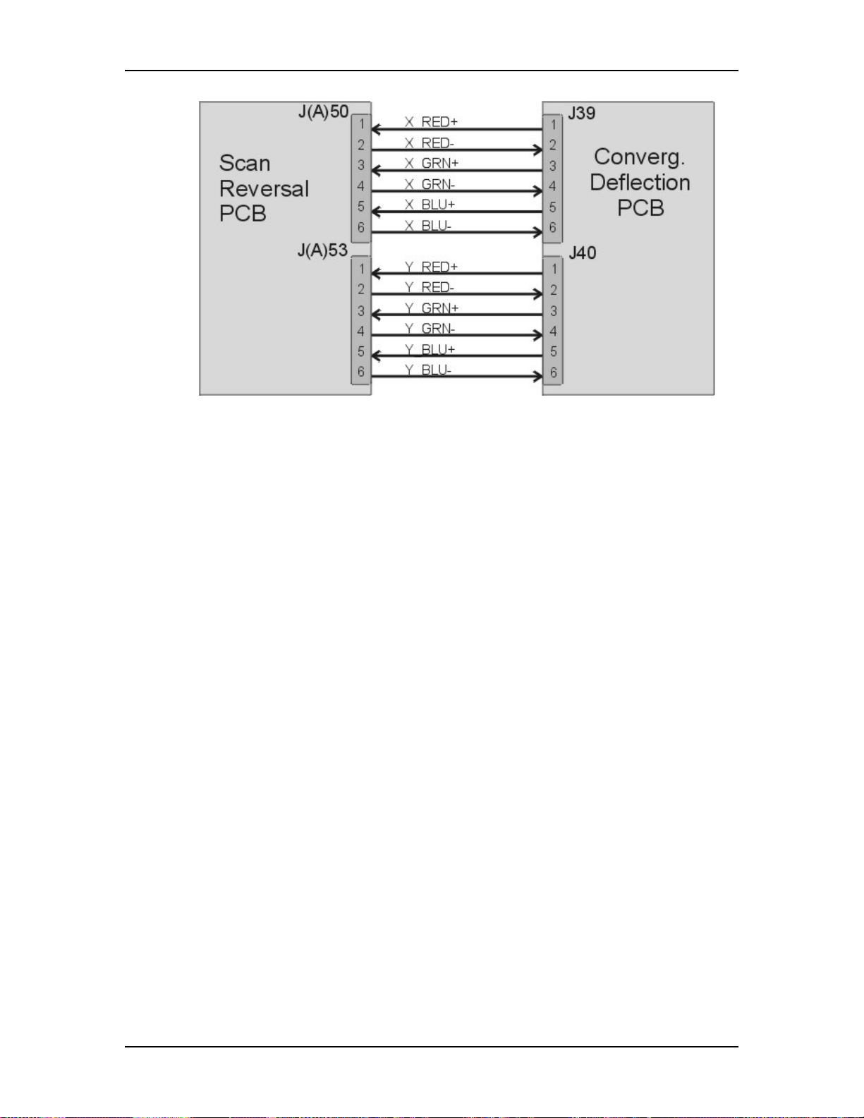
Chapter 5---Electronics
Figure 5-22
Scan Reversal PCB I/O Diagram.
5-36 Model 250 Service Manual
Page 92

Chapter 5---Electronics
Figure 5-23
Model 250 Service Manual 5-37
Scan Reversal PCB I/O Diagram for Horizontal Vertical Deflection PCB.
Page 93

Chapter 5---Electronics
Figure 5-24
Scan Reversal PCB I/O Diagram for CRT Yokes.
Scan Reversal PCB - Operation
The Scan Reversal PCB has several functions. It provides an interface for scan
reversal, and provides for horizontal width adjustment. The Scan Reversal PCB
outputs the convergence and deflection waveforms that drive the CRT
convergence and deflection yokes, and it contributes significantly to the CRT
Protection circuit.
The Scan Reversal PCB provides an interface for reversing the projection mode
from front to rear projection and from upright to inverted (upside down) mounting
projection setups. The projection modes are changed by switching a jumper from
one connector to another on the Scan Reversal PCB. J100 and J101 are for
horizontal scan connections. J53 and J53A are the vertical scan connections, and
J50 and J50A are convergence jumper connections. The Model 250 comes set for
5-38 Model 250 Service Manual
Page 94

Chapter 5---Electronics
front/upright projection. This means the horizontal scan jumper is plugged into
J100, the vertical scan jumper is plugged into J53, and the convergence jumper is
plugged into J50.
NOTE:
Whenever the horizontal scan jumper is switched from front projection to
rear projection, the convergence must also be switched from J50 to J50A.
The Scan Reversal PCB sends two signals (FRONT/REAR and
FLOOR/CEILING) back to the Horizontal Vertical Deflection PCB, which sends
the signals back to the System Controller PCB through the IIC data bus. This
allows the System Controller PCB to properly output convergence and shading
data, however the shading, convergence, geometry will need to be adjusted after
switching deflection modes.
The Scan Reversal PCB receives the deflection waveforms from the Horizontal
Vertical Deflection PCB. The horizontal deflection waveforms go through the
horizontal size adjustment inductors (L1, L2, and L3) and is output to the
Deflection Yokes on the CRT without any further signal processing. The vertical
deflection waveforms pass through the Scan Reversal PCB without any further
signal processing. The convergence data passes through the Scan Reversal PCB to
the Convergence Yokes on the CRT without any further signal processing.
The Scan Reversal PCB provides for the adjustment of horizontal scan width.
Inductor L1 adjusts the red horizontal width, and L5 adjusts the blue horizontal
width. L3 increases the horizontal size range of red and blue.
The Scan Reversal PCB contains two major components of the CRT Protection
circuit. The first component is the DEFL_OK signal that goes back to the
Horizontal Vertical Deflection PCB. The Scan Reversal PCB has a sensing
inductor (coil) that detects the presence of a horizontal and vertical deflection
waveform for each CRT. These sense lines combine to drive the DEFL_OK
signal. If any of the deflection waveforms are not present, the DEFL_OK signal
goes low. As the /SWEEP_OK signal it shuts down the G1 and G2 regulator
voltages on the Video Amplifier PCB. It also shuts down the high voltage section
of the High Voltage Power Supply (see CRT Protection section of Ch. 7--
Troubleshooting).
The other component of the CRT Protection circuit on the Scan Reversal PCB is
the H_LOCK+ and H-LOCK- signals. These signals are actually one voltage (+15
V) that forms a series circuit through each vertical and horizontal deflection yoke
connector on each CRT. If any of the deflection yokes are not properly or
securely installed, the H_LOCK- signal shuts down the horizontal amplifier on
the Horizontal Vertical Deflection PCB (see CRT Protection section of Ch. 7--
Troubleshooting).
Model 250 Service Manual 5-39
Page 95

Chapter 5---Electronics
Scan Reversal PCB - Service Adjustments
Figure 5-25
Physical layout of the Scan Reversal PCB.
Horizontal Size adjustment
The Horizontal size adjustment must be performed after the Horizontal Vertical
Deflection PCB is replaced.
Tools Needed
Delrin .100 hex alignment tool
Equipment Needed
No equipment needed
To adjust the horizontal size coils (see Figure 5-25):
4. Remove the rear cover and pull the Interlock switch out to the Service
Mode position.
5. Power ON the projector by IR Remote or PC, and allow it to stabilize for a
minimum of 15 minutes
6. Use the X-hatch test pattern.
7. Hide Blue. View Red and Green.
8. If the Red image is outside the Green image on both sides, or inside the
Green image on both sides, use a Delrin .100 hex alignment tool to adjust
the Red horizontal size coil to correct the error. If the Red image is outside
the Green image on one side and inside of Green on the other side, this is
most likely caused by Red not being centered correctly and can be
corrected with the centering adjustment (User’s Guide, Chapter 5).
If the Red horizontal size coil does not completely eliminate the size error
between Red and Green, balance the difference on both sides to allow for
easier convergence.
9. Repeat Steps 4 and 5 above for Blue while hiding Red.
5-40 Model 250 Service Manual
Page 96

Chapter 5---Electronics
10. Recheck all Geometry and Convergence settings and readjust wherever
necessary.
11. Replace the rear cover.
Front/Rear Projection Jumper Settings
In the procedures below each of the jumpers mentioned have a specific purpose:
J100 and J101 are the horizontal scanning jumpers, J 53 and J53A are the vertical
scanning jumpers, and J50 and J50A are the convergence jumpers.
CAUTION
Do not attempt to switch jumpers while the
!
projector is operating. The projector must be powered OFF when Scan
Reversal Jumpers are being changed.
Front/Rear Jumper Setting (Horizontal Reverse)
!
The Horizontal Scan Reversal Jumper reverses the image projection for
front or rear projection. Figure 5-25 illustrates the jumpers’ location on the
Scan Reversal Board.
!
The Model 250 Projector is shipped with the jumper plugs inserted in J50
and J100 for front/upright projection (see Table 5-1 for other
orientations).
To set the Horizontal Scan Jumper:
1. Power off the projector by IR Remote or PC, and allow the cooling fans to
run until they shut off automatically).
2. Turn the AC Circuit Breaker to the OFF position and unplug the AC
Power Cord.
3. Remove the rear cover.
4. Verify that the Horizontal Scan Reversal jumper is plugged into J100 and
the convergence jumper is plugged into J50 for front projection (see
Figure 5-25 and Table 5-1).
5. Switch the Horizontal Scan Reversal jumper to J101 and the Convergence
Jumper to JA50 for rear projection (see Figure 5-25 and Table 5-1).
6. Replace the projector cover.
7. Power ON the projector and allow it to stabilize for a minimum of 15
minutes. It is recommended that the projector be operating for a least one
hour before performing shading adjustments.
8. Recheck centering, convergence, and shading when changing jumpers for
front or rear screen projection.
Model 250 Service Manual 5-41
Page 97

Chapter 5---Electronics
Table 5-1
Orientation
Front/Floor
Projection orientation jumper settings.
Convergence.
P50 goes to:
Vertical.
P53 goes to:
J50 J53 J100
Horizontal.
P100 goes to:
(Upright)
Front/Inverted*
Rear/Floor
JA50 JA53 J101
JA50 J53 J101
(Upright)
Rear/Inverted*
*
CAUTION!
see
NOTE:
Whenever the horizontal scan jumper is switched from front projection to
below
J50 JA53 J100
rear projection, the convergence must also be switched from J50 to J50A.
Floor/Ceiling Jumper Setting
The Ceiling/Floor jumpers invert the image vertically for use in some situations
that use dual mirror projection setups.
CAUTION!
mounted in the inverted (upside down) position,
The Model 250 Projector can not be
however there are
dual mirror applications where the vertical scan jumper will need to be
changed to the inverted setting (JA53).
Figure 5-21 illustrates the location of the jumpers on the Scan Reversal Board.
The Model 250 Projector is shipped in the normal vertical projection position with
the jumper plug inserted into J53. For an inverted vertical setup this jumper plug
must be inserted into JA53. (see Table 5-1 for other orientations).
To invert the vertical image:
1. Power off the projector by IR Remote or PC, and allow the cooling fans to
run until they shut off automatically.
2. Turn the AC Circuit Breaker to the OFF position and unplug the AC
Power Cord.
3. Remove the rear cover.
4. Verify that the Vertical Scan Jumper is plugged into J53 for upright
projection. (see Figure 5-25 and Table 5-1).
5. Switch the Vertical Scan Jumper to JA53 for inverted projection. The
Convergence Jumper will not need to be changed for inverted projection
unless the Horizontal Scan Jumper is being changed.
6. Replace the rear cover.
5-42 Model 250 Service Manual
Page 98

Chapter 5---Electronics
7. Power ON the projector and allow it to stabilize for a minimum of 15
minutes. It is recommended that the projector be operating for a least one
hour before performing shading adjustments.
8. When changing jumpers for floor or ceiling screen projection, Centering,
Convergence and Shading must be rechecked.
Scan Reversal PCB - Remove and Replace
The Scan Reversal PCB is located on the front side of the Electronic Module (see
Figure 5-2).
Tools Needed
#1 Pozi-drive Phillips-head screwdriver
Parts Needed
Scan Reversal PCB p/n 102585
To remove the Scan Reversal PCB:
1. Power off the projector by IR Remote or PC, and allow the cooling fans to
run until they shut off automatically.
2. Turn the AC Circuit Breaker to the OFF position and unplug the AC
Power Cord.
3. Remove the projector rear cover.
4. Disconnect seven connectors (seeFigure 5-25): J52, J54, J64, J65, J66, J50
(or J50A), and J100 (or J101). To remove, push in slightly, squeeze the
tabs, and then pull connector out.
5. Move all cables out of the way.
6. Remove the four Pozi-drive screws (see Figure 5-25) and lift the board off
the Electronics Module.
7. Reinstall in the reverse order from above.
5.9 Video Amplifier PCB
Video Amplifier PCB - Main Functions
!
Amplification of video signals and driving the cathode of all three CRTs
!
Sensing the cathode beam current for all three CRTs
!
G1 regulator for all three CRTs
!
Blanking drive section
!
Phosphor protection for all three CRTs
!
G2 regulator and adjustment of black level (screen) for all CRTs
!
DC restoration for the video signals
!
CRT interface for focus, heater voltage and ARC ground
Model 250 Service Manual 5-43
Page 99

Chapter 5---Electronics
Video Amplifier PCB - Inputs
RGB_VIDEO - image pre-amp signals from the Video Processor PCB (about 0.5
Vpp).
RESTORE - image DC restorations pulse from Video Processor PCB, logic level
positive going 4% duty cycle.
BLANKING - Blanking signal, logic F type.
G1_SUPPLY - supply for G1 grid on CRTs from High Voltage Power Supply
(about -150 V).
G1_BIAS - brightness control line from Video Processor PCB (0-5 VDC).
RGB_G2 - G2 (black level) control lines from Video Processor PCB (0-3.1 V).
G2_SUPPLY - supply for G2 grid on CRTs from High Voltage Power Supply
(about 1200 V).
RGB_ FOCUS - Focus supply for CRTs from the High Voltage Power Supply
(approximately 7 kV).
SWEEP_OK - deflection status line from the Horizontal Vertical Deflection PCB.
+80 V - from the Low Voltage Power Supply
±15 V - input power for the analog circuitry from the Low Voltage Power Supply.
6.2 V - input power for the CRT filaments heaters from the Low Voltage Power
Supply.
5-44 Model 250 Service Manual
Page 100
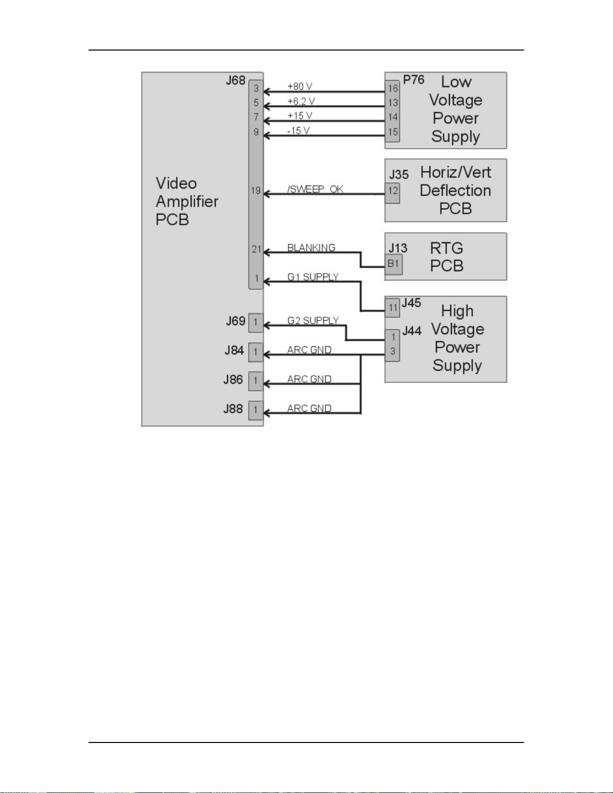
Chapter 5---Electronics
Figure 5-26
Video Amplifier PCB I/O Diagram
Model 250 Service Manual 5-45
 Loading...