

Page 1
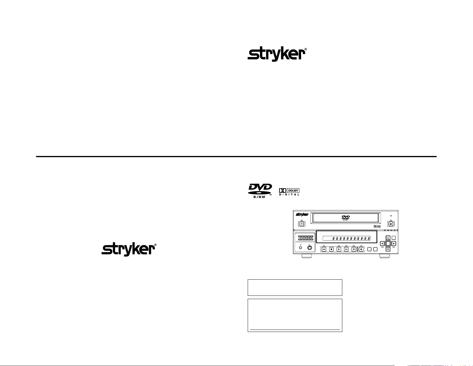
240-020-505 DVD RECORDER
DVD RECORDER
1000-400-802 Rev.B
LLT0087-001D
240-020-505
OPERATE
AUDIO
CH1
CH2
PHONES REV
Thank you for purchasing this product. Before operating this
unit, please read the instructions carefully to ensure the best
possible performance.
For Customer Use :
Enter below the Serial No. which is located on the bottom
of the unit.
Retain this information for future reference.
Model No. 240-020-505
Serial No.
DOLBY DIGITAL
LPCMMPEG
TITLE
STOP PLAY
DVD RECORDER
CHAPTER
FWD PAUSE REC
INSTRUCTIONS
BUSY
OPEN/CLOSE
OPTION DV Y/C LINE
SET UP
TOP
MENU MENU
This instruction book is made from 100 % recycled paper.
SET
Page 2

IMPORTANT SAFEGUARDS
CONSIGNES DE SÉCURITÉ IMPORTANTES
1. Read all of these instructions.
2. Save these instructions for later use.
3. All warnings on the product and in the operating instructions should be adhered to.
4. Unplug this appliance system from the wall outlet before cleaning. Do not use liquid cleaners or aerosol cleaners.
Use a damp cloth for cleaning.
5. Do not use attachments not recommended by the appliance manufacturer as they may cause hazards.
6. Do not use this appliance near water - for example, near a bathtub, washbowl, kitchen sink, or laundry tub, in a
wet basement, or near a swimming pool, etc.
7. Do not place this appliance on an unstable cart, stand, or table. The appliance may fall, causing
serious injury to a child or adult, and serious damage to the appliance.
Use only with a cart or stand recommended by the manufacturer, or sold with the appliance. Wall
or shelf mounting should follow the manufacturer’s instructions, and should use a mounting kit
approved by the manufacturer. An appliance and cart combination should be moved with care.
Quick stops, excessive force, and uneven surfaces may cause the appliance and cart combination
to overturn.
8. Slots and openings in the cabinet and the back or bottom are provided for ventilation, and to insure reliable
operation of the appliance and to protect it from overheating, these openings must not be blocked or covered. The
openings should never be blocked by placing the appliance on a bed, sofa, rug, or other similar surface.
This appliance should never be placed near or over a radiator or heat register. This appliance should not be
placed in a built-in installation such as a bookcase unless proper ventilation is provided.
9. This appliance should be operated only from the type of power source indicated on the marking label. If you are
not sure of the type of power supplied to your home, consult your dealer or local power company. For appliance
designed to operate from battery power, refer to the operating instructions.
10. This appliance system is equipped with a 3-wire grounding type plug (a plug having a third (grounding) pin). This
plug will only fit into a grounding-type power outlet. This is a safety feature. If you are unable to insert the plug into
the outlet, contact your electrician to replace your obsolete outlet. Do not defeat the safety purpose of the grounding
plug.
11. For added protection for this product during a lightning storm, or when it is left unattended and unused for long
periods of time, unplug it from the wall outlet and disconnect the antenna or cable system. This will prevent
damage to the product due to lightning and power-line surges.
12. Do not allow anything to rest on the power cord. Do not locate this appliance where the cord will be abused by
persons walking on it.
13. Follow all warnings and instructions marked on the appliance.
14. Do not overload wall outlets and extension cords as this can result in fire or electric shock.
15. Never push objects of any kind into this appliance through cabinet slots as they may touch dangerous voltage
points or short out parts that could result in a fire or electric shock. Never spill liquid of any kind on the appliance.
16. Do not attempt to service this appliance yourself as opening or removing covers may expose you to dangerous
voltage or other hazards. Refer all servicing to qualified service personnel.
17. Unplug this appliance from the wall outlet and refer servicing to qualified service personnel under the following
conditions:
a. When the power cord or plug is damaged or frayed.
b. If liquid has been spilled into the appliance.
c. If the appliance has been exposed to rain or water.
d. If the appliance does not operate normally by following the operating instructions. Adjust only those controls
that are covered by the operating instructions as improper adjustment of other controls may result in damage
and will often require extensive work by a qualified technician to restore the appliance to normal operation.
e. If the appliance has been dropped or the cabinet has been damaged.
f. When the appliance exhibits a distinct change in performance - this indicates a need for service.
18. When replacement parts are required, be sure the service technician has used replacement parts specified by the
manufacturer that have the same characteristics as the original part. Unauthorized substitutions may result in fire,
electric shock, or other hazards.
19. Upon completion of any service or repairs to this appliance, ask the service technician to perform routine safety
checks to determine that the appliance is in safe operating condition.
PORTABLE CART WARNING
(symbol provided by RETAC)
S3125A
I II
1. Lire ce mode d'emploi jusqu'au bout.
2. Conserver ce mode d'emploi pour pouvoir s'y reporter ultérieurement.
3. Respecter tous les avertissements qui figurent sur l'appareil et dans le mode d’emploi.
4. Avant de nettoyer l'appareil, le débrancher de la prise secteur. Ne pas utiliser de produits de nettoyage liquides ni
en aérosols. Nettoyer l'appareil à l'aide d'un chiffon humide.
5. Ne pas utiliser d’accessoires non recommandés par le fabricant de l’appareil car ils risquent de présenter un danger.
6. Ne pas utiliser cet appareil à proximité d'eau - par exemple près d'une baignoire, d'un lavabo, d'un évier ou d'un
bac à lessive, dans un sous-sol humide, ou près d'une piscine, etc.
7. Ne pas placer cet appareil sur un chariot, un socle ou une table instables. L'appareil vidéo pourrait
tomber, blessant grièvement des enfants ou des adultes, et être sérieusement endommagé.
Utiliser exclusivement le chariot ou le socle recommandés par le fabricant, ou vendus avec l'appareil.
Pour tout montage de l'appareil sur un mur ou dans une étagère, respecter les instructions du
fabricant, et utiliser à cette fin l'accessoire de montage recommandé par le fabricant. L'appareil
monté sur son chariot devra être déplacé avec précaution. Des arrêts brusques, une force excessive
et des surfaces irrégulières pourraient provoquer le renversement de l'ensemble appareil-chariot.
8. Les fentes et les ouvertures du coffret ainsi qu'au dos et sur le fond de l'appareil sont prévues
pour l'aération ainsi que pour garantir un fonctionnement en toute sécurité de l'appareil et le protéger de toute
surchauffe, et ces ouvertures ne devront donc être ni obstruées ni recouvertes. Ne jamais bloquer les ouvertures
en plaçant l'appareil sur un lit, un sofa, un tapis ou toute surface similaire.
Ne jamais placer l’appareil à proximité d'un radiateur ou d'un appareil de chauffage ni dessus. Ne pas placer
l’appareil dans un support confiné, par exemple une bibliothèque, sans aération suffisante.
9. Cet appareil devra être alimenté exclusivement sur le type d'alimentation indiqué sur l'étiquette signalétique. En
cas de doute sur le type d'alimentation du local, consulter le détaillant de l'appareil ou la compagnie d'électricité
locale. Pour les appareils qui fonctionnent sur batterie, voir le mode d’emploi.
10. Cet appareil est équipé d'une fiche avec mise à la terre à 3 fils, (fiche possédant une troisième broche (broche de
mise à la terre)). Cette fiche ne rentrera que dans une prise secteur avec broche de mise à la terre. Ceci est une
mesure de sécurité. Si la fiche ne rentre pas dans la prise, faire remplacer la prise désuète par un électricien. Ne
pas rendre inutile la mesure de sécurité assurée par cette fiche avec mise à la terre.
11. Pour renforcer la protection de l’appareil pendant un orage, ou si l'appareil est utilisé sans surveillance ou qu'il
reste longtemps inutilisé, le débrancher de la prise secteur et débrancher le système d'antenne ou de câble. Ceci
permettra d'éviter tout dommage de l'appareil dû à la foudre et aux surtensions de ligne.
12. Veiller à ce qu'il n'y ait rien de posé sur le cordon d'alimentation. Ne pas placer l'appareil de façon que l'on puisse
marcher sur son cordon.
13. Respecter les avertissements et les instructions qui figurent sur l’appareil.
14. Veiller à ne pas surcharger les prises secteur ni les cordons de rallonge ; cela pourrait provoquer ou feu ou un
choc électrique.
15. Ne jamais rien enfoncer dans les fentes du coffret de l'appareil car ces objets, quel qu'ils soient, pourraient
toucher des points soumis à des tensions dangereuses ou court-circuiter des pièces, provoquant un risque de feu
ou de choc électrique. Ne jamais renverser aucun liquide d'aucune sorte sur l'appareil.
16. Ne pas tenter de réparer l'appareil soi-même. En ouvrant ou en retirant les couvercles, l'on risque de s'exposer à
des tensions dangereuses. Confier toutes les réparations à un personnel de réparation qualifié.
17. Débrancher l'appareil de la prise secteur et s'adresser à un personnel de réparation qualifié dans les cas suivants:
a. Si le cordon ou la fiche d'alimentation sont endommagés ou effilochés.
b. Si du liquide a été renversé sur l'appareil.
c. Si l'appareil a été exposé à la pluie ou à l'eau.
d. Si l'appareil ne fonctionne pas normalement bien que l'on respecte les instructions de fonctionnement. Ne
régler les commandes qui sont abordées dans le mode d'emploi; en effet, un mauvais réglage des autres
commandes pourrait provoquer des dommages et nécessitera souvent des réparations coûteuses par un
technicien qualifié pour remettre l'appareil en ordre de marche.
e. Si l'appareil est tombé ou si son coffret a été abîmé.
f. Si l'appareil présente une altération nette de ses performances, signalant un besoin de réparation.
18. Si l'on a besoin de pièces de rechange, veiller à ce que le technicien de réparation utilise exclusivement les pièces
de rechange spécifiées par le fabricant ou des pièces ayant les mêmes caractéristiques que les pièces d'origine.
Les pièces de rechange non autorisées risquent de provoquer un feu, un choc électrique ou d’autres dangers.
19. Après tout travail d'entretien ou de réparation de l'appareil, demander au technicien de réparation d'effectuer les
vérifications de sécurité pour s'assurer que l'appareil est en bon ordre de marche.
PORTABLE CART WARNING
(symbol provided by RETAC)
S3125A
Page 3
Safety Precautions
Precautions de Securite
CAUTION
RISK OF ELECTRIC SHOCK
DO NOT OPEN
CAUTION: TO REDUCE THE RISK OF ELECTRIC SHOCK.
DO NOT REMOVE COVER (OR BACK).
NO USER-SERVICEABLE PARTS INSIDE.
REFER SERVICING TO QUALIFIED SERVICE PERSONNEL.
The lightning flash wish arrowhead symbol, within an equilateral
triangle is intended to alert the user to the presence of uninsulated
“dangerous voltage” within the product's enclosure that may be of
sufficient magnitude to constitute a risk of electric shock to persons.
The exclamation point within an equilateral triangle is intended to
alert the user to the presence of important operating and
maintenance (servicing) instructions in the literature accompanying
the appliance.
Changes or modifications not approved by Stryker could void the
user’s authority to operate the equipment.
Information for USA
This device complies with Part 15 of the FCC Rules. Changes or
modifications not approved by Stryker could void the user’s authority
to operate the equipment.
INFORMATION (FOR CANADA)
• This Class B digital apparatus complies with Canadian ICES-003.
®
MEDICAL ELECTRICAL EQUIPMENT
WITH RESPECT TO ELECTRICAL SHOCK, FIRE,
MECHANICAL AND OTHER SPECIFIED HAZARDS
ONLY IN ACCORDANCE WITH
UL.60601-1, CAN/CSA C22.2 NO.601.1
56PA
WARNING:
The battery used in this DVD recorder must be replaced by a
Stryker authorized service dealer only.
WARNING:
Disposal of product should follow National, State and Local Laws.
WARNING
It should be noted that it may be unlawful to re-record prerecorded tapes, records, or discs without the consent of the
owner of copyright in the sound or video recording, broadcast, or cable programme and in any literary, dramatic, musical or artistic work embodied therein.
WARNING
This apparatus is Medical Equipment.
Please make sure to use “hospital grade” power supply cord
specified by Stryker.
Classifications
• Class : I
• Type : No applied parts
• Moisture Protection : Ordinary
• AP/APG Category : No
• Operation Mode : Continuous
ATTENTION
RISQUE D’ELECTROCUTION
NE PAS OUVRIR
ATTENTION: POUR EVITER TOUT RISQUE D’ELECTROCUTION
SE REFERER A UN AGENT QUALIFIE EN CAS DE PROBLEME.
AVERTISSEMENT:
La plaque d’identification (numéro de série) se trouve sur le
panneau arrière de l’appareil.
Les changements ou les modifications non approuvés par Stryker
peuvent annuler l’autorisation pour le client d’utiliser l’appareil.
RENSEIGNEMENT (POUR CANADA)
• Cet appareil numérique de la classe B est conforme à la norme
NMB-003 du Canada.
WITH RESPECT TO ELECTRICAL SHOCK, FIRE,
MECHANICAL AND OTHER SPECIFIED HAZARDS
NE PAS OUVRIR LE BOITER.
ACCUNE PIECE INTERIEURE N’EST.
A REGLER PAR L’UTILISATEUR.
Le symbole de l’éclair à l’intérieur d’un triangle équilatéral est
destiné à alerter l’utilisateur sur la présence d’une “tension
dangereuse” non isolée dans le boîtier du produit. Cette tension
est suffisante pour provoquer l’électrocution de personnes.
Le point d’exclamation à l’intérieur d’un triangle équilatéral est
destiné à alerter l’utilisateur sur la présence d’opérations
d’entretien importantes au sujet desquelles des renseignements
se trouvent dans le manuel d’instructions.
*Ces symboles ne sont utilisés qu’aux Etats-Unis.
®
MEDICAL ELECTRICAL EQUIPMENT
ONLY IN ACCORDANCE WITH
UL.60601-1, CAN/CSA C22.2 NO.601.1
56PA
AVERTISSEMENT :
La pile utilisée dans ce graveur de DVD doit être remplacée
excessivement par un service après-vente Stryker agréé.
AVERTISSEMENT :
La mise au rebut du produit doit respecter les lois nationales, des
états et locales.
AVERTISSEMENT :
Noter que le réenregistrement de bandes ou de disques
préenregistrés sans l’autorisation du détenteur des droits
d’auteur de l’enregistrement sonore ou vidéo, d’une émission
diffusée sur les ondes ou d’un programme câblé, ainsi que
de toute oeuvre littéraire, dramatique, musicale ou artistique
qui y est contenue, peut constituer une infraction à la loi.
Classifications
• Classe : 1
• Type : Non applicable
• Protection contre l’humidité : Ordinaire
• Catégorie AP/APG : Non
• Mode de fonctionnement : Continu
III
IV
Page 4
Stryker Endoscopy
Stryker Endoscopy
5900 Optical Court
San Jose , CA 95138
Te l:1. 800. 624. 4422
Supplement
This apparatus is designed for rack mounting or is used close to other apparatus.
In order to keep the best performance and furthermore for electromagnetic compatibility we recommend to use cables
not exceeding the following lengths:
Port Cable Length
AC IN Exclusive cable 2.5 meters
Y/C Shielded cable 3 meters
VIDEO LINE Shielded cable 3 meters
AUDIO LINE Shielded cable 3 meters
REMOTE (9P) Shielded cable 3 meters
DV Shielded cable 3 meters
PHONES Shielded cable 3 meters
FOOT SWITCH Non-shielded cable 1.5 meters
LAN (FOR SERVICE) Shielded Twist Pair cable 10 meters
USB Shielded cable 1.8 meters
The inrush current of this apparatus is 19 amperes.
Caution:
5 Where there are strong electromagnetic waves or magnetism, for example near a radio or TV transmitter, transformer,
motor, etc., the picture and sound may be disturbed. In such a case, please keep the apparatus away from the
sources of the disturbance.
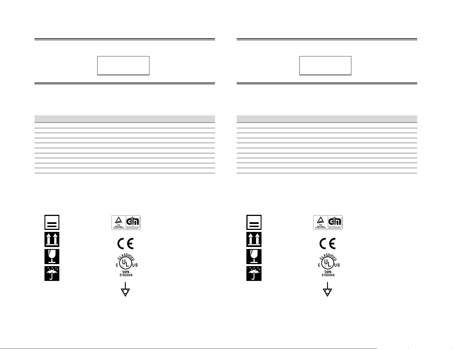
Pictographs
Package Label
8
Pile up max. 8 level
Body
Indicates proof of conformity of a medical product
with the essential requirments of the Medical Device
Directive (93/42/EEC)
5900 Optical Court
San Jose , CA 95138
Te l:1. 800. 624. 4422
Supplément
Ce matériel est conçu pour le montage en baie et peut être utilisé à proximité d’autres appareils.
Afin de maintenir la meilleure performance et notamment pour la compatibilité électromagnétique, nous recommandons
l’utilisation de câbles n’excédant pas les longueurs suivantes :
Port Câble Longueur
AC IN Câble exclusif 2,5 mètres
Y/C Câble blindé 3 mètres
VIDEO LINE Câble blindé 3 mètres
AUDIO LINE Câble blindé 3 mètres
REMOTE (9P) Câble blindé 3 mètres
DV Câble blindé 3 mètres
PHONES Câble blindé 3 mètres
FOOT SWITCH Câble non blindé 1,5 mètres
LAN (FOR SERVICE) Câble à paire torsadée blindé 10 mètres
USB Câble blindé 1,8 mètres
L’appel de courant de cet appareil est de 19 ampères.
Attention :
5 Dans les endroits où il y a des ondes électromagnétiques puissantes ou du magnétisme, par exemple près d’un
émetteur radio ou TV, d’un transformateur, d’un moniteur, etc., l’image et son peuvent être distordus. Dans ce cas,
veuillez éloigner l’appareil des sources de perturbations.
Pictogrammes
Étiquette de l’emballage
8
Empilement max. 8 niveaux
Corps de l’appareil
Atteste de la conformité d’un produit médical avec
les exigences essentielles de la Directive sur les
appareils médicaux (93/42/CEE).
Top-Bottom
Fragile
Do not get wet
Indicates proof of conformity to applicable European
Economic Community Council directives and to
harmonized standards published in the official
journal of the European Communities.
Tested and certified by UL to UL60601-1. If this mark
R
appears with the indicators “C” and “US”, the product
is certified for both the U. S. and Canadian markets,
to the applicable U. S. and Canadian standards.
Ground terminal
Haut – Bas
Fragile
R
Ne pas mouiller
V
Atteste de la conformité aux directives du Conseil
de la Communauté économique européenne et aux
normes harmonisées publiées dans le journal
officiel des Communautés européennes.
A subi les essais et a été certifié UL à UL60601-1.
Si cette marque apparaît avec les indications « C »
et « US », le produit est certifié à la fois sur le
marché américain et sur le marché canadien, aux
normes américaines et canadiennes applicables.
Prise de terre
VI
Page 5
SAFETY PRECAUTIONS
PRECAUTIONS DE SECURITE
Classifications
• Class : I
• Type : No applied parts
• Moisture Protection : Ordinary
• AP/APG Category : No
• Operation Mode : Continuous
Warning Notice
1. Insert this plug only into effectively earthed threepin power outlet.
2. If any doubt exists regarding the earthing, consult a
qualified electrician.
The wires in this mains lead are coloured in accordance
with the following code;
GREEN-and-YELLOW : EARTH
BLUE : NEUTRAL
BROWN : LIVE
As the colours of the wires in the mains lead of this
apparatus may not correspond with the coloured
markings identifying the terminals in your plug, proceed
as follows.
The wire which is coloured GREEN-AND-YELLOW
must be connected to the terminal in the plug which is
marked with the letter E or by the safety earth symbol
or coloured GREEN or GREEN-AND-YELLOW. The
wire which is coloured BLUE must be connected to the
terminal which is marked with the letter N or which is
coloured BLACK. The wire which is coloured BROWN
must be connected to the terminal which is marked
with the letter L or coloured RED.
FOR YOUR SAFETY
IMPORTANT (In the United Kingdom)
Mains Supply (AC 230 V `)
WARNING – THIS APPARATUS
MUST BE EARTHED
POWER SYSTEM
Connection to the mains supply
This unit operates on voltage of 100 V to 240 V AC, 50
Hz/60 Hz.
WARNING:
TO REDUCE THE RISK OF FIRE OR
ELECTRIC SHOCK, DO NOT EXPOSE THIS
APPLIANCE TO RAIN OR MOISTURE.
CAUTION
To prevent electric shock, do not open the cabinet. No
user serviceable parts inside. Refer servicing to
qualified service personnel.
Note:
The rating plate (serial number plate) is on the bottom
of the unit.
The main power switch is on the back side of the unt.
Changes or modifications not approved by Stryker could
void the user’s authority to operate the equipment.
The use of interconnection with other equipment not
complying with the equivalent safety requirements of
this equipment may lead to a reduced level of safety of
the resulting system. Consider:
- whatever equipment is used in the patient vicinity
- evidence that the safety certification of the equipment
or system has been performed in accordance to the
appropriate IEC 60601-1 and/or IEC 60601-1-1
harmonized National Standard.
When clean the equipment, please use dry cleaning
cloth or moistened cloth with mild detergent solution.
Do not spill any liquid onto this DVD recorder.
Do not sterilize this DVD recorder.
Classifications
Classe : I
Type : Aucune pièce appliquée
Protection contre l’humidité
Catégorie AP/APG : No
Mode de fonctionnement : continu
Note d’avertissement
1. Insérer cette prise uniquement dans une prise
secteur à trois broches avec mise à la terre.
2. Si vous avez le moindre doute sur la mise à la terre,
consultez un électricien qualifié.
IMPORTANT (Royaume-Uni)
Alimentation principale (230 V CA )
AVERTISSEMENT – CET APPAREIL DOIT
Les fils du câble d’alimentation de cet appareil sont
codés avec les couleurs suivantes :
VERT-JAUNE : TERRE
BLEU : NEUTRE
MARRON : PHASE
Les fils du câble d’alimentation de cet appareil peuvent
ne pas correspondre aux codes de couleur identifiant
les bornes de votre prise. Il faut donc procéder ainsi :
Le fil vert-jaune doit être relié à la borne de la prise
portant la lettre E ou le symbole de mise à la terre
ou de couleur verte ou vert-jaune.
Le fil bleu doit être relié à la borne portant la lettre N
ou de couleur noire. Le fil marron doit être relié à la
borne portant la lettre L ou de couleur rouge.
ETRE RELIE A TERRE
: ordinaire
pour votre sécurité
SYSTEME D’ALIMENTATION
Cet appareil fonctionne sur une tension courant
alternatif de 100 à 240 V, 50 Hz/60 Hz.
AVERTISSEMENT :
POUR EVITER LE RISQUES D’INCENDIE OU
D’ELECTROCUTION, N’EXPOSER
L’APPAREIL NI A L’HUMIDITE NI A LA PLUIE.
ATTENTION
Pour éviter les chocs électriques, ne pas ouvrir le coffret.
Aucune pièce à l’intérieur n’est à régler par l’utilisateur.
Confier les opérations d’entretien au personnel de
service qualifié.
Remarque:
La plaque signalétique (plaque du numéro de série)
est située au bas de l’appareil.
L’interrupteur d’alimentation pr incipal est situé à l’arrière
de l’appareil.
Les changements ou modifications qui ne sont pas
approuvés par Stryker peuvent annuler l’autorité de
l’utilisateur de faire fonctionner cet équipement.
L’utilisation d’ACCESSOIRE non conformes aux
exigences de sécurité de cet équipement peut mener
à une réduction du niveau de sécurité du système. Les
éléments suivants doivent être pris en considération
lorsqu’on décide d’utiliser des accessoires ou non:
l’utilisation de l’accessoire à PROXIMITÉ DU CLIENT
la preuve que la certification de sécurité de l’ACCESSOIRE
a été exécutée conformément aux normes nationales
harmonisées IEC 60601-1 et/ou IEC 60601-1-1.
Pour nettoyer l’équipement, utiliser un chiffon de
nettoyage sec ou un chiffon de nettoyage mouillé avec
une petite quantité d’détergent doux.
Ne pas renverser de liquide dans l’enregistreur DVD.
La stérilisation n’est pas requise.
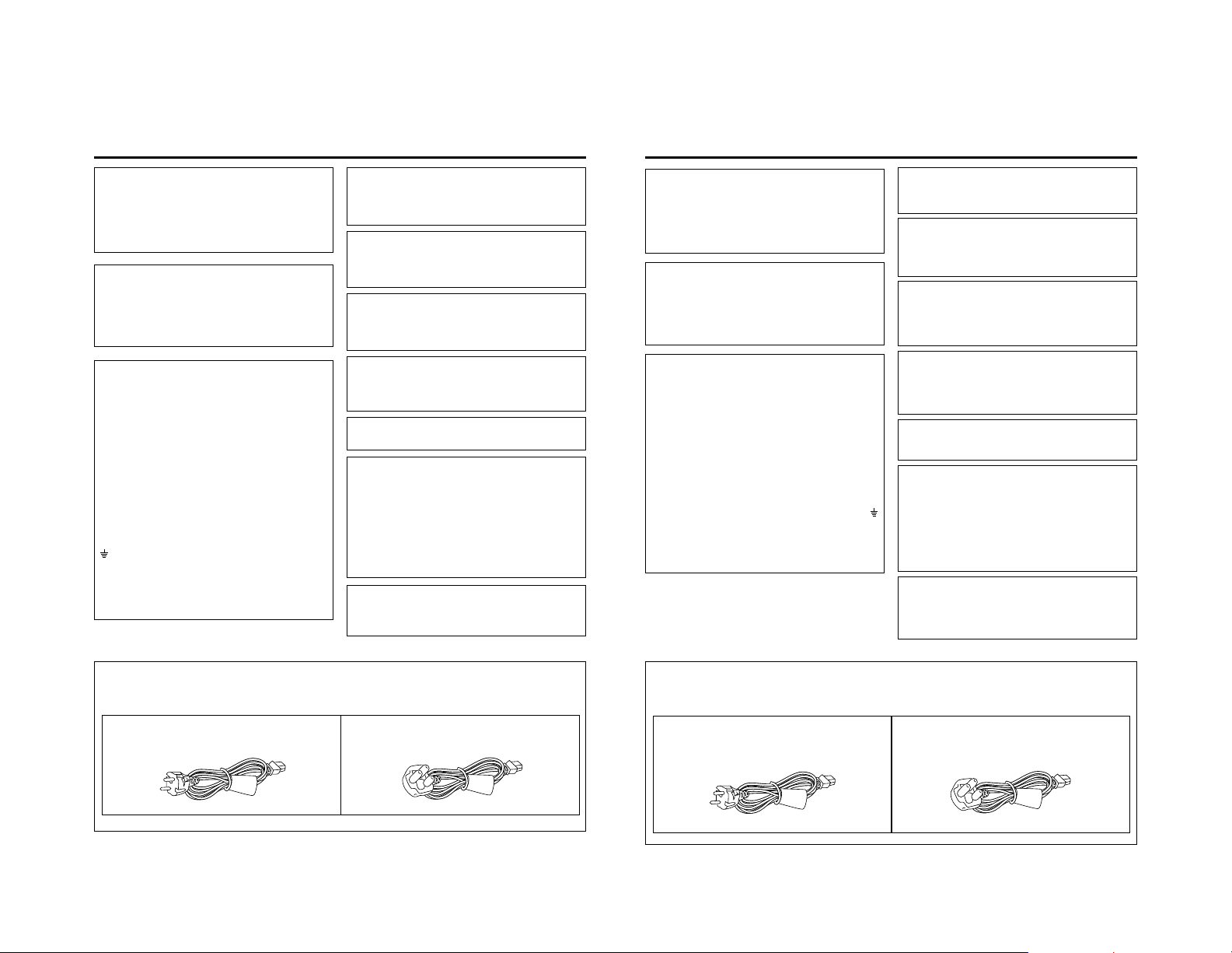
FOR YOUR SAFETY PLEASE READ THE FOLLOWING TEXT CAREFULLY.
Appropriate mains cable must be used in each local area, since the other type of mains cable is not suitable.
FOR CONTINENTAL EUROPE, ETC.
Not to be used in the U.K.
Caution for AC Mains Lead
FOR U.K. ONLY
If the plug supplied is not suitable for your socket outlet,
please use appropriate one.
VII
POUR VOTRE SECURITE, LIRE ATTENTIVEMENT LE TEXTE SUIVANT :
Utiliser le câble approprié selon le type de prise de votre pays. Les câbles ne sont pas compatibles l’un avec l’autre.
POUR L’EUROPE CONTINENTALE
Ne pas utiliser au Royaume-Uni.
Précaution d’utilisation du câble d’alimentation
POUR LE ROYAUME-UNI SEULEMENT
Si la fiche d’alimentation ne correspond pas à la prise
secteur, il faut la remplacer par une fiche appropriée.
VIII
Page 6

Supplement for medical Use
Medical electrical equipment needs special precautions regarding EMC and needs to be installed and put into service
according to the EMC information provided below.
Portable and mobile RF communications equipment can affect medical electrical equipment.
WARNING : The use of accessories, transducers and cables other than those specified,with the exception of transducers
Information of Cables and Accessories
Make sure to use specified Accessories as described in the user manual P/N 1000-400-802, in order to maintain
compliance with IEC60601-1-2.
WARNING : The equipment or system should not be used adjacent to or stacked with other equipment and that if
WARNING : The use accessories, transducer or cable with equipment or system other than those specified may result
Guidance and Manufacturer’s declaration-electromagnetic emissions
The customer or the user of the Model 240-020-505 should assure that it is used in such an environment.
The Model 240-020-505 is intended for use in the electromagnetic environment specified below.
and cables sold by the manufacturer of the equipment or system as replacement parts for internal
components ,may result in increase emissions or decreased immunity of the equipment or system.
adjacent or stacked use is necessary,the equipment or system should be observed to verify normal
operation in the configuration in which it will be used. Prior to using it in a surgical procedure, consult the
tables below for guidance in placing the equipment.
in increased emissions or decreased immunity of the equipment or system.
Emission Test Compliance Electromagnetic environment-guidance
RF emissions Group 1
CISPR11/EN55011
RF emissions Class B
CISPR11/EN55011
Harmonic emissions Class A
IEC/EN 61000-3-2
Voltage Fluctuations/ Complies
Flicker emissions
IEC/EN 61000-3-3
The Model 240-020-505 uses RF energy only for its internal
function. Therefore, its RF emissions are very low and are not
likely to cause any interference in nearby electronic equipment.
The Model 240-020-505 is suitable for use in all establishments,
including domestic establishments and those directly connected
to the public low-voltage power supply network that supplies
buildings used for domestic purposes.
Guidance and Manufacturer’s declaration-electromagnetic immunity
The Model 240-020-505 is intended for use in the electromagnetic environment specified below.
The customer or the user of the Model 240-020-505 should assure that it is used in such an environment.
Immunity Test IEC/EN 60601 Compliance Level Electromagnetic
Electrostatic
discharges(ESD)
IEC/EN 61000-4-2
Electrical fast
Tr ansients/burst
IEC/EN 61000-4-4
Surge
IEC/EN 61000-4-5
Voltage dips, short
interruptions and
voltage variations
on power supply
input lines
IEC/EN 61000-4-11
Power frequency
(50 Hz/60 Hz)
Magnetic Field
IEC/EN 61000-4-8
Test Level environment-guidance
+/- 6 kV : Contact
+/- 8 kV : Air
+/- 2 kV : AC mains
+/- 1 kV : Signal lines
+/- 2 kV : Common mode
+/- 1 kV :
Differential mode
<5 % Ut
(>95 % dip in 100 V and
240 V) : for 0.5 cycle
40 % Ut
(60 % dip in 100 V and
240 V) : for 5 cycles
70 % Ut
(30 % dip in 100 V and
240 V) : for 25 cycles
<5 % Ut
(>95 % dip in 100 V and
240 V) : for 5 s
3 A/m
Floor should be wood, concrete or
ceramic tile. If floors are covered with
synthetic material, the relative
humidity should be at least 30 %.
Mains power quality should be that
of a typical commercial or hospital
environment.
Mains power quality should be that
of a typical commercial or hospital
environment.
Mains power quality should be that
of a typical commercial or hospital
enviroment. If the user of the Model
240-020-505 requires continued
operation during power mains
interruptions, it is recommended that
the Model 240-020-505 be powered
from an uninterruptible power supply
or a battery.
If image distortion occurs, it may be
necessary to position the Model 240-
020-505 further from sources of
power frequency magnetic fields or
to install magnetic shielding.
The power frequency magnetic field
should be measured in the intended
installation location to assure that it
is sufficiently low.
IX
X
Page 7
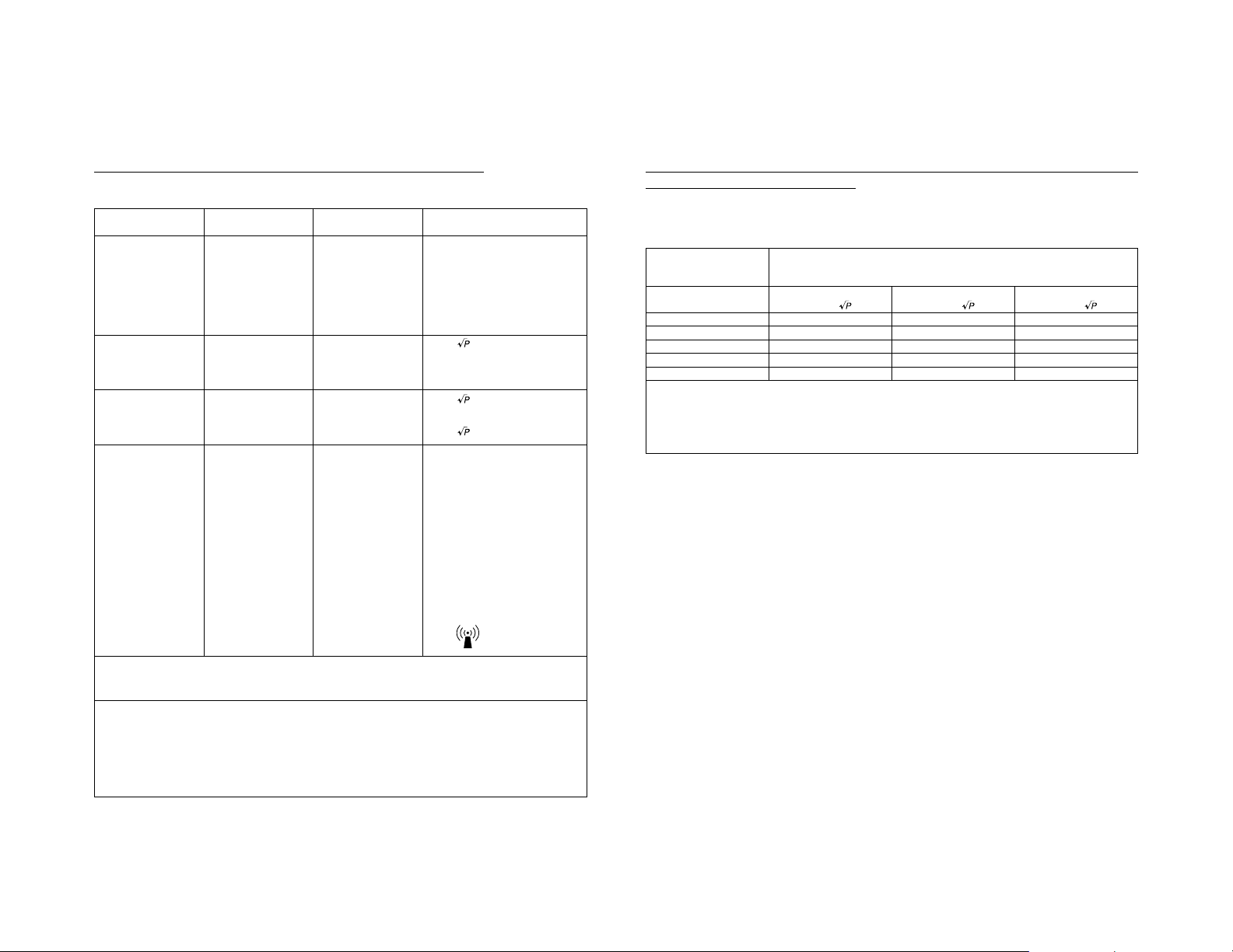
Guidance and Manufacturer’s declaration-electromagnetic immunity
The Model 240-020-505 is intended for use in the electromagnetic environment specified below.
The customer or the user of the Model 240-020-505 should assure that it is used in such an environment.
Immunity Test IEC/EN 60601 Compliance Level Electromagnetic environment-
RF Common mode/
Conducted
Susceptibility
IEC/EN 61000-4-6
Radiated RF
Electromagnetic
Fields
IEC/EN 61000-4-3
Test Level guidance
Por table and mobile RF communications
equipment should be used no closer
to any part of the Model 240-020-505,
including cables than the recommended
separation distance calculated from
the equation applicable to the
frequency of the transmitter.
Recommended separation distance
3 Vrms
3 Vrms
d =1.2
150 kHz to 80 MHz
3 V/m
80 MHz to 2.5 GHz
3 V/m
d =1.2 : 80 MHz to 800 MHz
d =2.3 : 800 MHz to 2.5 GHz
Where P is the maximum output
power rating of the transmitter in
watts (W) according to the transmitter
manufacturer and d is the recommended
separation distance in meters (m).
Field strengths from fixed RF
transmitters, as determined by an
electromagnetic site survey,
be less than the compliance level in
each frequency range.
Interference may occur in the vicinity
of equipment marked with the
following symbol:
b
a
should
Recommended separation distance between portable and mobile RF communications
equipment and the Model 240-020-505
The Model 240-020-505 is intended for use in the electromagnetic environment in which radiated RF disturbances are
controlled. The customer or the user of the Model 240-020-505 can help prevent electromagnetic interference by
maintaining a minimum distance between portable and mobile RF communications equipment (transmitters) and the
Model 240-020-505as recommended below, according to the maximum output power of the communications equipment.
Rated maximum separation distance according to frequency of transmitter
output power of m
transmitter
W 150 kHz to 80 MHz 80 MHz to 800 MHz 800 MHz to 2.5 GHz
0.01 0.12 0.12 0.23
0.1 0.38 0.38 0.73
1 1.2 1.2 2.3
10 3.8 3.8 7.3
100 12 12 23
For transmitters rated at a maximum output power not listed above, the recommended separation distance d in
meters (m) can be estimated using the equation applicable to the frequency of the transmitter, where P is the
maximum output power rating of the transmitter in watt (W) according to the transmitter manufacturer.
NOTE 1 At 80 MHz and 800 MHz, the separation distance for the higher frequency range applies.
NOTE 2 These guidelines may not apply in all situations. Electromagnetic propagation is affected by absorption
and reflection from structures, objects and people.
d =1.2 d =2.3 d =1.2
NOTE 1 At 80 MHz and 800 MHz, the higher frequency range applies.
NOTE 2 These guidelines may not apply in all situations. Electromagnetic propagation is affected by absorption
and reflection from structures, objects and people.
a
Field strengths from fixed transmitters, such as base stations for radio (cellular/cordless) telephones and land
mobile radios, amateur radio, AM and FM radio broadcast and TV broadcast cannot be predicted theoretically
with accuracy. To assess the electromagnetic environment due to fixed RF transmitters, an electromagnetic site
survey should be considered. If the measured field strength in the location in which the Model 240-020-505 is
used exceeds the applicable RF compliance level above, the Model 240-020-505 should be observed to verify
normal operation. If abnormal performance is observed, additional measures may be necessary, such as reorienting or relocating the Model 240-020-505.
b
Over the frequency range 150 kHz to 80 MHz, field strengths should be less than 3 V/m.
XI
XII
Page 8

Thank you for purchasing
this DVD Recorder.
Main Features
● Recording of DVD-R/DVD-RW (video mode only) and DVD+R/
DVD+RW.
● Composite video, YC separate, DVI and DV signals are
supported as video inputs; furthermore, analog or DV signals
are supported as audio inputs.
● A keyboard can be used as an alternative to front panel buttons.
● The title and chapter menus can be created either
automatically or manually.
● NTSC / PAL selectable
● Dual mode foot switch terminal available.
Recording can be turned ON/OFF and insertion of chapter/
index are possible using the external switch terminal.
● Equipped with an index search feature.
Allows automatic playback upon locating a specific index
position.
● Equipped with a timelapse recording feature.
Intermittent recording enables recording over long hours.
● Equipped with the DAILY REC feature.
Allows recording to start/stop at a designated time on a daily
basis.
Trademarks & Copyrights
● , Dolby and the Double “D” symbols are
trademarks of Dolby Laboratories.
● The copying, broadcasting, screening, or rental of
copyrighted material without the authorization of the
copyright holder is prohibited by law.
Copyright Protection Technology
This DVD recorder utilizes copyright protection technology
and is protected by US patents and intellectual property as
owned by Macrovision and other copyright holders. The
permission of Macrovision is required in order to use this
copyright protection technology, and except in situations
where special permission has been granted by that
company, said technology is restricted to domestic usage
and for certain other viewing purposes. The disassembly
and/or modification of this DVD recorder is also prohibited.
Copyrights
● The recording, dubbing, or playing of software containing
a copyright protection signal is not possible on this DVD
recorder.
● The usage of audio or video discs created using this DVD
recorder either for financial gain or in broadcasting for
widespread viewing may result in the legally-enforceable
rights of the copyright holder being infringed.
● Unless the permission of the copyright holder has been
obtained, audio or video discs created using this DVD
recorder are to be used for personal enjoyment only.
Contents
Introduction
Overview of Functions ......................................................................................................................................................... 4
Precautions for DVD Recorder Use..................................................................................................................................... 5
Precautions for Disc Usage ................................................................................................................................................. 6
Details Regarding Discs ...................................................................................................................................................... 7
Component Names & Functions
Front Panel .......................................................................................................................................................................... 9
Rear Panel......................................................................................................................................................................... 12
LCD Display and On-Screen Content
LCD Display....................................................................................................................................................................... 14
On-Screen Content ........................................................................................................................................................... 16
Status Messages ......................................................................................................................................................... 16
Event Messages .......................................................................................................................................................... 18
Alarm Messages .......................................................................................................................................................... 19
Preparation
Connections ...................................................................................................................................................................... 20
Power Connections............................................................................................................................................................ 21
Tur ning the Power On & Off ............................................................................................................................................... 21
Inserting & Removing Discs .............................................................................................................................................. 22
Using a Keyboard .............................................................................................................................................................. 23
Attach the provided ferrite core.................................................................................................................................... 23
Setting & Displaying the Date & Time................................................................................................................................ 24
Settings & Controls for Recording
DVD Recording.................................................................................................................................................................. 26
Preparing a Disc for Recording ......................................................................................................................................... 27
Pre-Recording Settings ..................................................................................................................................................... 29
Specifying the Disc Status Created when the Disc was Finalized..................................................................................... 30
Setting the Encoding Format for Audio & Video ................................................................................................................ 31
Adjusting of Audio Recording Levels ................................................................................................................................. 32
Checking the Video Input .................................................................................................................................................. 33
Title & Chapter Menus ....................................................................................................................................................... 34
Selecting Styles for Title & Chapter Menu ......................................................................................................................... 35
Changing Styles for Title & Chapter Menus....................................................................................................................... 36
Recording
Recording Sequence ......................................................................................................................................................... 37
Recording with the Front Panel ......................................................................................................................................... 38
Inserting Chapter Marks Manually or Automatically .................................................................................................... 39
Using the Foot Switch to Perform Recording..................................................................................................................... 39
Using a Keyboard to Control Recording ............................................................................................................................ 40
Timelapse Recording ........................................................................................................................................................ 41
DAILY REC (Daily Recording) ........................................................................................................................................... 42
Finalizing (for Playback on Other DVD Players) ................................................................................................................ 43
Title & Chapter Menu Settings
Changing Chapter Menus (THUMBNAIL EDIT Screen) .................................................................................................... 44
Changing & Naming Thumbnails for Chapter Menus ........................................................................................................ 45
Changing & Checking Chapter Menu Styles ..................................................................................................................... 47
Ending the Editing of Chapter Menus ................................................................................................................................ 49
Changing & Checking Title Menu Styles & Names............................................................................................................ 50
Playback
Playing Back a Disc ........................................................................................................................................................... 54
Fast & Slow Playback........................................................................................................................................................ 56
Playing the Previous or Next Chapter/Title........................................................................................................................ 56
Index Writing and Index Search......................................................................................................................................... 57
Setup Menu
Setting the Setup Menu ..................................................................................................................................................... 59
Restoring to Default Settings ....................................................................................................................................... 59
Setup Menu Configuration................................................................................................................................................. 60
Setup Menus ..................................................................................................................................................................... 61
DISC MENU Screen .......................................................................................................................................................... 62
INPUT SELECT MENU Screen ......................................................................................................................................... 63
SYSTEM MENU Screen .................................................................................................................................................... 63
DVD MENU Screen ........................................................................................................................................................... 66
RECORDER MENU Screen .............................................................................................................................................. 68
REMOTE MENU Screen ................................................................................................................................................... 70
DISPLAY MENU Screen.................................................................................................................................................... 72
CLOCK ADJUST MENU Screen ....................................................................................................................................... 73
NETWORK MENU Screen ................................................................................................................................................ 73
Others
Changing the Signal System (NTSC / PAL) ...................................................................................................................... 74
Specifications .................................................................................................................................................................... 75
Troubleshooting ................................................................................................................................................................. 76
Service and Claims ........................................................................................................................................................... 77
Warranty Statement........................................................................................................................................................... 78
2
3
Page 9

Introduction
Overview of Functions
Video and audio signals from this DVD recorder’s input terminals can be recorded to
DVD-R / DVD-RW (video mode only) or DVD+R / DVD+RW. (☞ Page 26)
The types of signals that can be used are as follows.
Video: Composite video, YC separate, DV signals (including audio) or DVI signals
Audio: Analog audio or DV signals (including video)
A wide range of recording methods are supported. The appropriate method is to be
selected in accordance with the intended mode of use.
● The REC, PAUSE, and STOP buttons on the front panel can be used for standard operations. (☞ Page 38)
● Recording operations can be carried out using the REC CONTROL panel. Furthermore, a keyboard can also be used when
recording via this panel. (☞ Page 40)
●
Recording can be operated via the external switch that is connected to the foot switch terminal. (
The title and chapter menus can be created either automatically or manually. (☞ Page 44)
Five different patterns have been provided as display styles for the title and chapter menus. Each of these patterns is characterized
by different thumbnail characteristics (i.e., number, position, and size) and background images displayed on the title and
chapter menu screens.
When a display style is selected during the recording of content to a DVD, this DVD recorder will automatically create the title
and chapter menus in accordance with this style.
The DVD MENU screen can be used to modify the thumbnail and background display characteristics of each of the display
styles.
In addition, the THUMBNAIL EDIT screen and the CHAPTER MENU EDIT screen can be used to modify the display style and
thumbnail images for chapter menus, and also to input chapter names and comments. The input of names or comments is
carried out using a keyboard connected to one of the recorder’s USB terminals.
The TITLE MENU EDIT screen can be used to modify the display style for the title menu and to enter title names.
This DVD recorder can be used to play discs that it has created. (☞ Page 54)
● Once a disc has been finalized, it can also be played on other DVD players.
☞ Page
39)
Precautions for DVD Recorder Use
Storage & Usage Locations
The storage and usage of this DVD recorder in the following
types of location should be avoided.
● Areas at temperatures which deviate by a significant degree
above or below the permitted service temperature range
(i.e., 5°C to 35°C).
● Areas at humidities which deviate by a significant degree
above or below the permitted service humidity range (i.e.,
20% to 80% RH).
● Areas where a large amount of dust or sand is present.
● Areas where the DVD recorder may come into contact with
oily smoke or steam, such as in kitchens or in their
immediate vicinity.
● Areas that are unstable or where significant vibration occurs.
● Areas where condensation occurs readily.
● Areas where strong magnetic fields are generated by
transformers, motors, or the like.
● Areas where transceivers, mobile phones, and other
wireless-communication devices are present.
● Areas that are subjected to X-ray irradiation or where
corrosive gases are present. (This precaution must be
strictly observed.)
Handling
● Ensure that this DVD recorder is placed on a flat, horizontal
surface for use.
● Do not place heavy objects such as a monitor on top of the
DVD recorder.
● Do not inser t foreign objects into the disc tray opening.
● Be careful not to get your fingers clamped when loading
the disc to prevent injury.
● Do not block the fan’s ventilation holes.
● Avoid knocking or dropping this DVD recorder.
● When the DVD recorder is to be moved, ensure that any
DVD it contains is removed in advance.
● If the DVD recorder is not to be used for an extended period
of time, please set the POWER switch to OFF to avoid
wasting electricity.
Cleaning the Exterior (with the power off)
Use a soft cloth when cleaning the outside of this DVD
recorder.
Do not use paint thinners or organic solvents as cleaning
agents.
Failure to observe these precautions can result in discoloration
or melting of exterior surfaces.
When stubborn dirt is present, wipe away using a cloth soaked
in a dilute neutral solvent.
Always use the power cord provided with this DVD
recorder.
The usage of a different type of cord or a damaged cord can
result in the outbreak of fire or electric shocks.
The power cord supplied with this DVD recorder should
not be used with any other device.
Before connecting this DVD recorder to other
devices, turn those devices off and then carry out
setup procedures as described in the
corresponding user’s manuals.
The DVD drive unit is an expendable part. Although the
service life of the DVD drive unit differs depending on
the usage environment of the customer, replacement
every 1000 hours as a guide is recommended. (☞ Page
64 “TOTAL RECORDING TIME”)
Precautions Regarding Condensation
Condensation
When cold water is poured into a glass and droplets of
water form on its outer surface, this moisture is referred
to as “condensation”.
When condensation occurs
Condensation can cause water droplets to adhere to the
DVD recorder’s internal lens, thus making normal
operation impossible.
Condensation occurs easily in the following situations,
and the appropriate care should be taken.
• When the DVD recorder is moved from a cold location
into a warm room.
• When the room containing the DVD is rapidly heated.
• When an air conditioner’s air duct is pointing straight at
the DVD recorder.
In situations where it is likely that condensation will occur,
remove any DVD that may be present in this DVD recorder
and then turn the power on. As the interior heats up,
condensation will be less likely to occur.
Condensation is a principal cause of the inability to play
discs and other similar problems. In this type of situation,
allow the DVD recorder to remain inactive with its power
on for several hours. If the problem persists after this
period of time has elapsed, contact either the store where
this DVD recorder was purchased or your Authorized
dealer.
Extended Periods of Inactivity
Performance may deteriorate over extended periods of
inactivity; for this reason, the power should be turned on
and the DVD recorder should be operated at regular
intervals.
Compensation for Damaged Content
Stryker accepts no responsibility whatsoever for damages
incurred as a result of an inability to play or record audio
and video content in the rare event that this DVD recorder,
a disc fails to operate correctly.
It is recommended that discs containing important content
be backed up at regular intervals (i.e., on a yearly basis).
Although digital signals do not deteriorate, storage
environments can have an effect on a disc’s aging
characteristics, and this may result in an inability to play
or record.
If a disc should break, there will be no way to recover
data from it.
Proper playback of discs recorded using this DVD recorder
on all devices is not guaranteed.
4
5
Page 10
Introduction
Precautions for Disc Usage
Care of Discs to Ensure High-Quality Playback
Fingerprints, dust, or any other similar contamination of the surface of a disc can lead to distortion in the playback of recorded
video and audio. For this reason, it is good practice to wipe each disc with a soft cloth before use.
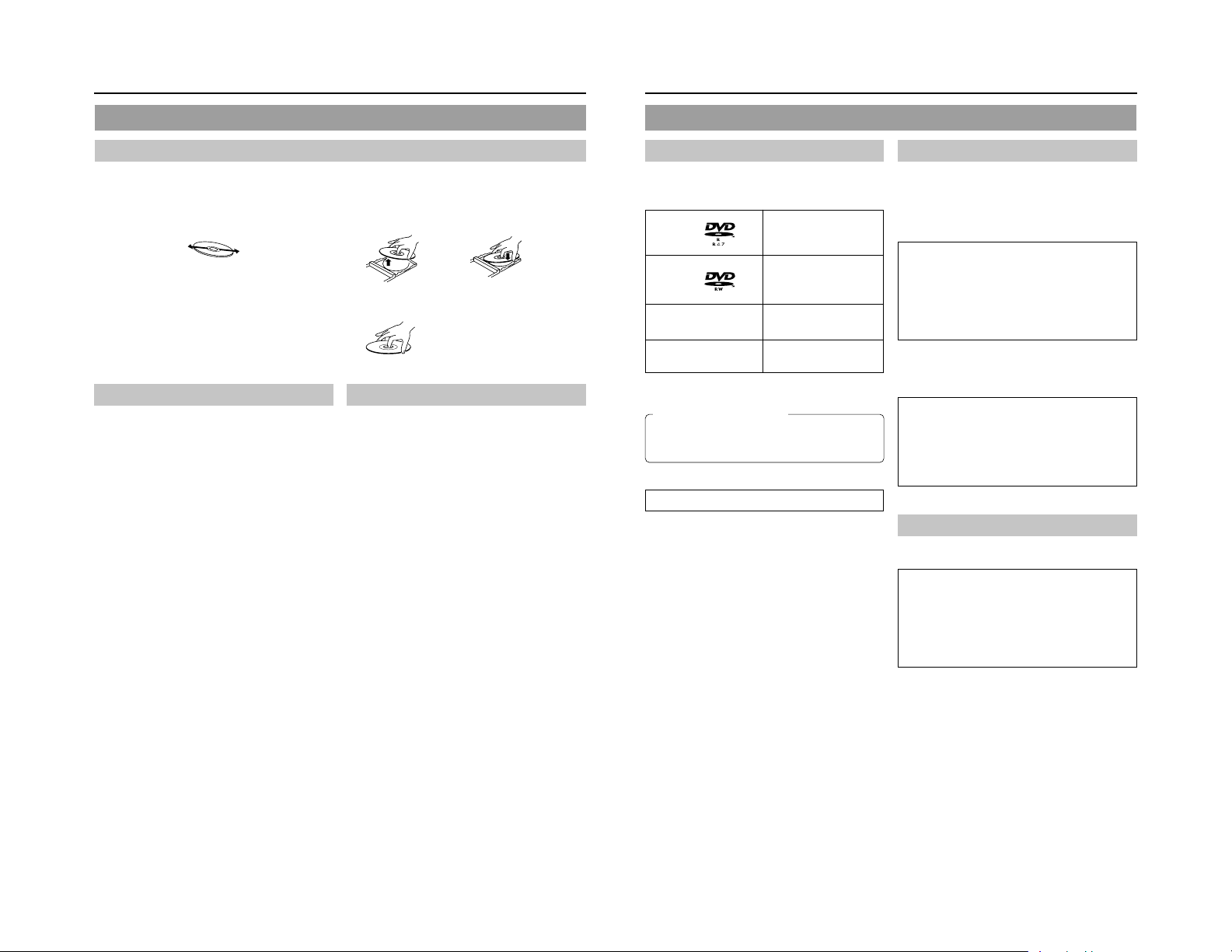
Looking After Discs
● Using a soft cloth, wipe the disc gently from the inside to
the outside.
● If stubbor n dirt is present on the surface of a disc, wipe first
using a slightly wet cloth and then using a dry cloth.
● Paint thinners, organic solvents, analog record cleaning
agents, anti-static sprays, and the like must never be used.
Failure to observe this precaution can lead to discs being
permanently damaged.
Additional Notes on Disc Handling
Never wipe a disc using paint thinners, organic solvents,
alcohol, or record-cleaning fluid.
Do not use disc protectors or scratch guards.
Stickers and other types of paper label should not be applied.
Do not use discs from which stickers or labels have been
removed.
Do not use discs on which illustrations or text has been printed
using a commercially-available label printer. First create a disc
using the unit before printing.
The use of non-circular discs (i.e., heart or rectangular
shaped), warped discs, and cracked discs can lead to
breakage of the DVD recorder.
Handling Discs
● Removing a disc ● Placing a disc in its case
● Correct method for holding a disc
Your hands or fingers should not
come into contact with the
recording surface when holding
a disc.
Storing Discs
Avoid storing discs in any of the following locations.
• Areas with high levels of humidity or dust, or areas where
mold is present.
• Areas exposed to direct sunlight or close to heating
equipment.
•Vehicle interiors during summer months.
Ta ke care to avoid dropping or knocking discs.
Place discs in cases and stack these cases for storage.
Discs can be deformed or cracked as a result of stacking,
leaning, or dropping when not inside a case.
Details Regarding Discs
Discs for Recording & Playback
The following shows the discs that can be recorded to and played
using this DVD recorder, in addition to the corresponding display
marks or logos.
DVD-R 12 cm: 4.7 GB
DVD-RW 12 cm: 4.7 GB
DVD+R 12 cm: 4.7 GB
DVD+RW 12 cm: 4.7 GB
* Certain characteristics and properties of a disc can render
them unsuitable for recording or playback.
Recommended manufacturers
DVD-R : JVC, Maxell 2×, 4×, 8×
DVD-RW : JVC 2×, 4×
DVD+R : JVC 2.4×, 4×, 8×
DVD+RW: JVC 2.4×, 4×
DVD-R/-RW and DVD+R/+RW Details
DVD-R : Only discs that conform with DVD-R Standard 2.0
(video mode) can be used.
DVD-RW : Discs of Version 1.1 or later can be used.
Although Version 1.1 of the DVD-RW Standards
allows the selection of either video mode or VR mode
for recording, this DVD recorder performs recording
in video mode only.
*Version 1.0 of the DVD-RW Standards does not
support video-mode recording, and for this
In terms of recording characteristics, DVD-R / DVD-RW (video
mode) and DVD+R / DVD+RW differ as follows.
DVD-R / DVD+R
DVD-RW (video mode) / DVD+RW:
reason, the corresponding discs cannot be used.
• Each disc can be recorded only once. Accordingly, these
discs are recommended for use in archiving or long-term
storage.
• Once a disc has been finalized, it can also be played on
other DVD players.
• After viewing a disc, all data can be erased and it can be
used to record new content.
• Once a disc has been finalized, it can also be played on
other DVD players.
• It is possible to cancel the finalization and add a recording.
General Version 2.0
(video mode)
Version 1.1 or later
(video mode)
Finalizing
When a DVD-R / DVD-RW (video mode) and DVD+R/DVD+RW
has been finalized, it can be played in the same way as any
other DVD using a standard DVD player. (☞ Page 43)
Recording to unused sections of a disc and the
modification of titles or display styles can be carried
out as required before a disc is finalized.
• In the case of both DVD-Rs/DVD-RWs and DVD+Rs/
DVD+RWs, it is impossible to overwrite previously
recorded content with new data, even if the disc in question
has not yet been finalized. The deletion of specific sections
of data is also impossible.
• Regardless of whether or not finalization has been carried
out, it will not be possible to use this DVD recorder to
record new content to a DVD-R/DVD-RW and DVD+R/
DVD+RW that has been recorded using other devices.
Once a disc has been finalized, it can be used as a
standard DVD and its recorded audio and video can
be played on this and other DVD players.
• After finalizing, a disc’s titles can be selected from the top
menu.
• Additional recording will not be possible after finalizing.
• In the case of a DVD-RW or DVD+RW, it is possible to
cancel the finalization and add a recording.
• Although a finalized disc may in principle be played on
other DVD players, certain characteristics of the disc and
its recording conditions may make this impossible.
Playing Discs on this DVD recorder
This DVD recorder is capable of playing any discs that it has
created and finalized.
● The following conditions may occur when attempting to
play discs recorded using other devices on this DVD
recorder.
• Inability to play
• Block-type noise (i.e., mosaic)
• Interruptions in audio and/or video
• Unintentional stopping during playback
● Commercially-available DVD-Videos and DVD-ROMs
cannot be used.
6
7
Page 11
Introduction
Component Names & Functions
Details Regarding Discs (continued)
DVD Data Configuration
Generally speaking, the content recorded on a DVD is separated
into large units referred to as “titles”. A unique number called a
“title number” is assigned to each of these titles, and as a result,
any title can be immediately accessed using its title number. In
addition, each title can be divided into smaller units referred to
as “chapters”. Similarly, a unique number called a “chapter
number” is assigned to each of these chapters, and this allows
any chapter to be immediately accessed using its chapter
number.
Each recording made to a disc is stored as a single title. In this,
each pressing of the STOP button to leave Recording mode
constitutes a different recording. (This action is also referred to
as “title closing”.)
It is also possible to insert chapter marks to partition titles at the
desired points by pressing the REC button while recording. It is
possible to automatically add a chapter mark when recording is
temporarily stopped by pressing the PAUSE button. (Set from
the menu.) In addition, this DVD recorder can also be used to
automatically insert chapter marks at regular intervals.
(CHAPTER CREATION menu settings will be required for this
function.)
Disc
Title 1
Chapter 1 Chapter 2 Chapter 3
● Before a title is closed, it will be possible to modify the style
used for chapter menu display, to change the thumbnails used,
and to input thumbnail names.
● Before a disc is finalized, it will be possible to modify the style
used for the title menu and to input title names.
Title 2
Chapter 1 Chapter 2
8
Region Codes
One of six numbers referred to as “region codes” is assigned to
DVD content to control the global regions in which this content
may be viewed. If a DVD’s region code does not correspond to
the region code of the DVD player being used, it will not be
possible to play the disc.
● This DVD recorder assigns the region code “ALL” to the discs
that it records.
● It will not be possible to play discs to which region codes have
been assigned.
Screen Sizes
This DVD recorder is capable of recording video content for widescreen TVs (i.e., with a 16:9 aspect ratio).
In addition, signals for normal content with a 4:3 aspect ratio, for
squeezed content (i.e., where the left and right are compressed),
and for letterbox content (i.e., where the top and bottom of the
screen are black) can be recorded as is.
● Thumbnail creation method for use in the title/chapter menu
during wide-signal input can be selected in THUMBNAIL
FORM of the DVD MENU screen. (☞ Page 66)
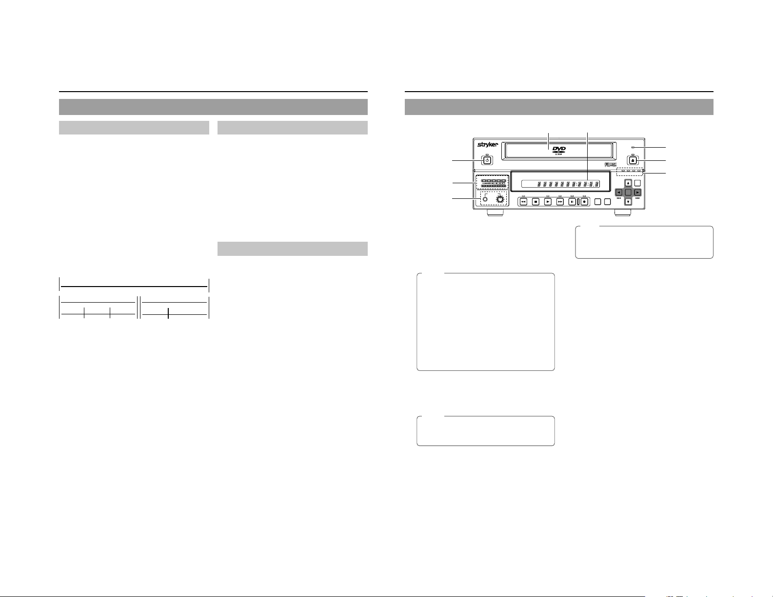
Front Panel
OPERATE
1
AUDIO
5
8
OPERATE button and indicator
1
● This button is used to make it ready for use. Press again to
disable operation (Operate OFF mode).
● The indicator’s lighting condition depends on the condition
of the DVD recorder and can be one of the following.
Lit in green : Operate ON.
Lit in orange : Operate OFF.
Notes
● The OPERATE button will have no effect if pressed
while the DVD recorder is in either Recording or
Recording Pause mode. This is also the case when
performing finalizing or erasing.
● The DVD recorder continues to use a small amount
of power even after it has been turned off using the
OPERATE button. If it will not be used for an extended
period of time, please set the POWER switch to OFF
to avoid wasting electricity.
● Do not tur n the power off when in Operate On mode
as this can result in the DVD recorder being
damaged.
● Malfunction may occur when switching to OPERATE
ON while pressing a key on a connected USB
keyboard.
Disc tray
2
The purpose of the disc tray is to hold DVDs.
This tray opens automatically when the OPEN/CLOSE button
is pressed. In addition, the OPEN/CLOSE button can be
pressed again to close the tray.
Notes
● Do not push the disc tray as it is opening or closing.
● Do not place objects other than discs on the disc
tray.
● Do not press down on the disc tray
BUSY indicator
3
This indicator flashes when the DVD recorder is in Recording
Pause mode or when it is performing time-consuming
operations such as title closing, finalizing, and erasing. None
of the DVD recorder’s buttons will have any effect if pressed
while the BUSY indicator is flashing.
OPEN/CLOSE button and indicator
4
● This button is used to open and close the disc tray.
In addition, the OPEN/CLOSE indicator is lit up while the
disc tray is opening, and also when it is open.
● In addition, “Finalize” will start when holding this button for
more than 3 seconds. (“Finalize” short cut)
CH1
CH2
PHONES REV
DOLBY DIGITAL
LPCMMPEG
STOP PLAY FWD PAUSE REC
62
BUSY
OPEN/CLOSE
3
4
OPTION DV Y/C LINE
TITLE
CHAPTER
TOP
MENU MENU
Note
The OPEN/CLOSE button will have no effect if pressed
while the DVD recorder is in either Recording or
Recording Pause mode. This is also the case when
performing finalizing or erasing.
Audio level indicator
5
These meters are used to indicate the current level of audio
on Channel 1 and Channel 2.
Specifically, the audio level meters indicate the audio recording
levels when the DVD recorder is in Recording mode, and the
audio playback levels when it is in Playback mode.
(Adjustment of the audio recording levels: ☞ Page 32.)
LCD display
6
The LCD display is used to present important information.
During recording or playback, for example, the title, chapter
number, and elapsed time are indicated on the LCD display.
(☞ Page 14 for more details.)
Video input indicators
7
OPTION indicator
This indicator is lit up or flashes when INPUT SELECT
from the INPUT SELECT MENU screen has been set to
DVI.
DV indicator
This indicator is lit up or flashes when INPUT SELECT
from the INPUT SELECT MENU screen has been set to
DV. Specifically, the indicator is lit up when an input signal
is present, and it flashes when no signal is present.
Y/C indicator
This indicator is lit up or flashes when INPUT SELECT
from the INPUT SELECT MENU screen has been set to
Y/C. Specifically, the indicator is lit up when an input signal
is present, and it flashes when no signal is present.
LINE indicator
This indicator is lit up or flashes when INPUT SELECT
from the INPUT SELECT MENU screen has been set to
LINE. Specifically, the indicator is lit up when an input signal
is present, and it flashes when no signal is present.
Phones jack and volume adjuster
8
The phones jack allows headphones to be connected to the
DVD recorder for monitoring of audio levels; in addition, the
headphone volume can be adjusted using the volume adjuster.
Note that this adjuster has no effect on the actual recording
levels.
SET UP
SET
7
9
Page 12
Component Names & Functions
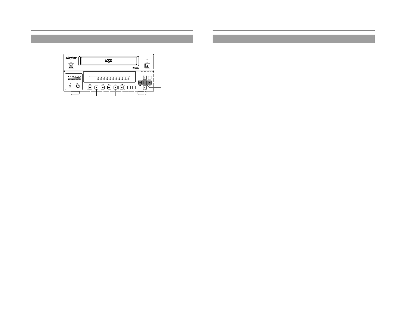
Front Panel (continued)
OPERATE
AUDIO
CH1
CH2
PHONES REV
REV button and indicator
9
● Press this button during playback or fast-forward mode to
start fast-reverse play. If pressed during fast-reverse play,
this button toggles the speed of fast-reverse play between
low speed and high speed.
● Press this button in still mode or during slow-forward play
to start slow-reverse play. If pressed during slow-reverse
play, this button toggles the speed of slow-reverse play
between low speed and high speed.
● The REV indicator is lit up during fast-reverse and slowreverse play.
STOP button
0
● This button has the following effect when pressed in
Recording or Recording Pause mode.
If EDIT MENU from the DVD MENU screen is set to
DISABLE, the DVD recorder stops recording (i.e., it
performs title closing).
If EDIT MENU from the DVD MENU screen is set to
ENABLE, the DVD recorder stops recording and the
THUMBNAIL EDIT screen is displayed. It will then be
possible to modify the chapter menu.
● When the STOP button is pressed in Playback mode, the
DVD recorder stops playback.
PLAY button and indicator
!
● If this button is pressed together with the REC button while
a recordable disc is inserted into the DVD recorder,
recording will be started.
● When the PLAY button is pressed in Recording Pause
mode, the DVD recorder restarts recording.
● When an unfinalized disc is inserted and this button is
pressed, playback of the most recent title starts.
● The PLAY indicator is lit up in Recording and Playback
modes.
FWD button and indicator
@
● Press this button during playback or fast-reverse mode to
start fast-forward play. If pressed during fast-forward play,
this button toggles the speed of fast-forward play between
low speed and high speed.
● Press this button in still mode or during slow-reverse play
to start slow-forward play. If pressed during slow-forward
play, this button toggles the speed of slow-forward play
between low speed and high speed.
● The FWD indicator is lit up during fast-forward and slowforward play.
TITLE
DOLBY DIGITAL
LPCMMPEG
CHAPTER
STOP PLAY FWD PAUSE REC
90!@#$%^
BUSY
OPEN/CLOSE
SET UP
)
*
&
⁄
TOP
MENU MENU
OPTION DV Y/C LINE
SET
¤
(
PAUSE button and indicator
#
● When this button is pressed while recording, the recorder
enters the recording pause mode.
● If this button is pressed during playback, the DVD recorder
switches to Still mode and freezes playback. If the PAUSE
button is then pressed again in Still mode, the DVD recorder
will advance playback by a single field.
● The PAUSE indicator is lit up in Recording Pause and Still
modes.
REC button and indicator
$
● If this button is pressed together with the PLAY button in
Stop mode, recording will be started.
• If the current disc is blank or title closing has been carried
out, a new title will be created and recording will start at
Chapter 1.
● When this button is pressed during recording, a new chapter
& index will be setup within the continuous video data.
● Press this button during playback to write index.
● If this button is pressed and held for more than 2 seconds
while the DVD recorder is stopped or inserted with no disc,
input signal encoded/decoded in MPEG will be output via
the VIDEO OUT terminal on the rear panel. This will continue
for as long as the button is held, and it allows the DVD
recording quality to be confirmed. Audio will be muted at
this time.
● The REC indicator is lit up in Recording and Recording
Pause modes.
TOP MENU button
%
If this button is pressed while the DVD recorder is in a playback
condition, the current DVD’s top menu (or title menu) will be
displayed on the monitor screen.
If the DVD does not contain a title menu, nothing will be
displayed when the TOP MENU button is pressed.
MENU button
^
If this button is pressed while the DVD recorder is in a playback
condition, the chapter menu for the currently selected title
will be displayed on the monitor screen.
If the DVD title does not contain a chapter menu, nothing will
be displayed when the MENU button is pressed.
SET UP button
&
● This button can be pressed to display the Setup Menu on
the monitor. A wide range of different menu settings can
then be made via the Setup Menu. (☞ Page 59)
In addition, the SET UP button can be pressed again to
hide the Setup Menu.
● If the SET UP button is pressed in Recording or Recording
Pause mode, setting data relevant to recording (i.e., video
bit rate and audio encoding format) will be displayed onscreen. In addition, the SET UP button can be pressed again
to hide this information.
● Press this button when in the Playback mode to display the
INDEX MANAGER screen.
When the INDEX MANAGER screen is displayed, press
this button to return to the original screen. (☞ Page 57)
[6] button
*
● This button is used to select menu items or setting values
when the Setup Menu is displayed.
● Press this button during playback to playback the next title.
● If a title menu or chapter menu is displayed, this button
can be used to select a menu number for playback.
Specifically, pressing of this button moves the selection
position upward.
● The 6 button can be used to adjust the audio recording
levels when the DVD recorder is stopped or in Recording
or Recording Pause mode.
• If AUDIO REC VOLUME MODE from the RECORDER
MENU (2/2) screen is set to BOTH and this button is
pressed while either the 8 or t button is being held, the
audio recording levels for both Channel 1 and Channel 2
will increase.
• If AUDIO REC VOLUME MODE from the RECORDER
MENU (2/2) screen is set to INDEPENDENCE and this
button is pressed while the 8 button is being held, the
audio recording level for Channel 1 will increase. Similarly,
if the 6 button is pressed while the t button is being
held, the audio recording level for Channel 2 will increase.
[7] button
(
● This button is used to select menu items or setting values
when the Setup Menu is displayed.
● Press this button during playback to playback the previous
title.
● If a title menu or chapter menu is displayed, this button
can be used to select a menu number for playback.
Specifically, pressing of this button moves the selection
position downward.
● The 7 button can be used to adjust the audio recording
levels when the DVD recorder is stopped or in Recording
or Recording Pause mode.
• If AUDIO REC VOLUME MODE from the RECORDER
MENU (2/2) screen is set to BOTH and this button is
pressed while either the 8 or t button is being held, the
audio recording levels for both Channel 1 and Channel 2
will decrease.
• If AUDIO REC VOLUME MODE from the RECORDER
MENU (2/2) screen is set to INDEPENDENCE and this
button is pressed while the 8 button is being held, the
audio recording level for Channel 1 will decrease. Similarly,
if the 7 button is pressed while the t button is being
held, the audio recording level for Channel 2 will decrease.
[8] button
)
● If a title menu or chapter menu is displayed, this button
can be used to select a menu number for playback.
Specifically, pressing of this button moves the selection
position to the left.
● This button can be pressed while the DVD recorder is
playing to move playback to the start of the current chapter.
● The 8 button can be used to adjust the audio recording
levels when the DVD recorder is stopped or in Recording
or Recording Pause mode.
• If AUDIO REC VOLUME MODE from the RECORDER
MENU (2/2) screen is set to INDEPENDENCE and either
the 6 or 7 button is pressed while this button is being
held, the audio recording level for Channel 1 will be
adjusted accordingly.
• If AUDIO REC VOLUME MODE from the RECORDER
MENU (2/2) screen is set to BOTH and either the 6 or 7
button is pressed while this button is being held, the audio
recording levels for both Channel 1 and Channel 2 will be
adjusted accordingly.
• If this button is pressed together with the t button, the
audio recording levels will be returned to their default
settings (i.e., unity gain).
[t] button
⁄
● If a title menu or chapter menu is displayed, this button can
be used to select a menu number for playback. Specifically,
pressing of this button moves the selection position to the
right.
● This button can be pressed while the DVD recorder is
playing to move playback to the start of the next chapter.
● The t button can be used to adjust the audio recording
levels when the DVD recorder is stopped or in Recording
or Recording Pause mode.
• If AUDIO REC VOLUME MODE from the RECORDER
MENU (2/2) screen is set to INDEPENDENCE and either
the 6 or 7 button is pressed while this button is being
held, the audio recording level for Channel 2 will be
adjusted accordingly.
• If AUDIO REC VOLUME MODE from the RECORDER
MENU (2/2) screen is set to BOTH and either the 6 or 7
button is pressed while this button is being held, the audio
recording levels for both Channel 1 and Channel 2 will be
adjusted accordingly.
• If this button is pressed together with the 8 button, the
audio recording levels will be returned to their default
settings (i.e., unity gain).
SET button
¤
● This button is used to confirm the selection of menu items
or setting values when the Setup Menu is displayed.
● When this button is pressed during normal screen display,
the counter from the DVD recorder’s LCD display will switch
to display of either the elapsed recording/playback time or
the remaining disc time.
10
11
Page 13
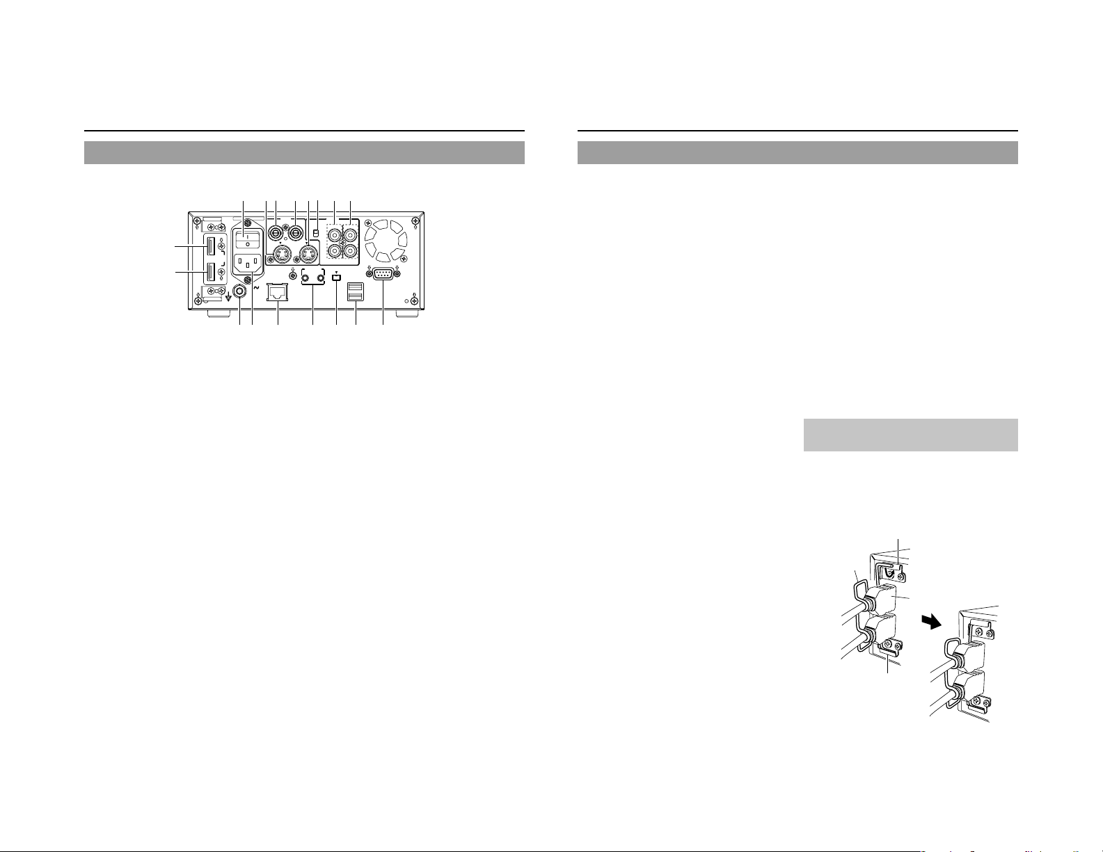
Component Names & Functions
Rear Panel
POWER
MAIN
^
&
IN
DVI
OUT
FOR SERVICE
AC IN
#@!09
VIDEO LINE IN terminal (BNC)
1
This terminal allows composite video signals to be input to
the DVD recorder.
In order to select these signals for input, set INPUT SELECT
from the INPUT SELECT MENU screen to LINE.
● SETUP from the SYSTEM MENU (1/2) screen should be
set in accordance with whether or not this input signal is a
setup signal. (NTSC only)
VIDEO Y/C IN terminal (4-pin)
2
This terminal allows YC separate video signals to be input to
the DVD recorder.
In order to select these signals for input, set INPUT SELECT
from the INPUT SELECT MENU screen to Y/C.
● SETUP from the SYSTEM MENU (1/2) screen should be
set in accordance with whether or not this input signal is a
setup signal. (NTSC only)
● This ter minal’s specification (i.e., S1 or S2) can be selected
using Y/C TERMINAL MODE from the SYSTEM MENU (2/
2) screen.
VIDEO LINE OUT terminal (BNC)
3
This terminal is used to connect the DVD recorder to a monitor.
● When the DVD recorder is in Stop or Recording mode, the
video input signal is output on the E-E screen as a
composite video signal.
● If the REC button is pressed and held for at least 2 seconds
while the DVD recorder is stopped, the input signal will be
subjected to MPEG encode/decode processing and output
via the VIDEO LINE OUT terminal. This will continue for as
long as the REC button is held, and it allows the DVD
recording quality to be confirmed.
● Playback from the DVD is output as a composite signal
when in Playback mode.
● The Setup Menu, title menu, chapter menus, and other
setting and control screens are displayed on the monitor
connected to this terminal.
● Status and alarm information is also displayed on-screen.
(The DISPLAY MENU screen can be used to indicate which
items are to be displayed.)
12345
VIDEO
LINE
Y/C
IN
67%
AUDIO
INPUT
LEVEL
IN
+
4dB
-
8dB
Y/C
OUT
FOOT SW
DV IN/OUT
1
2
VIDEO Y/C OUT terminal (4-pin)
4
For output of YC separate video signals.
● Information that is the same as that of the VIDEO LINE
OUT terminal is being output.
● This ter minal’s specification (i.e., S1 or S2) can be selected
using Y/C TERMINAL MODE from the SYSTEM MENU (2/
2) screen.
AUDIO INPUT LEVEL switch
5
This switch is used to set the standard level for audio input.
+4dB : The standard level is set to +4 dB.
–8dB : The standard level is set to –8 dB.
AUDIO IN terminals (RCA × 2)
6
These terminals allow analog audio signals to be input to the
DVD recorder.
● In order to select these signals for input, set INPUT SELECT
from the INPUT SELECT MENU screen to LINE or Y/C.
AUDIO OUT terminals (RCA × 2)
7
These terminals allow analog audio signals to be output from
the DVD recorder.
● When the DVD recorder is in Stop or Recording mode, the
audio input signals (i.e., E-E signals) are output via these
terminals.
● Audio from the DVD is output when in Playback mode.
RS-232C REMOTE terminal (D-sub 9-pin female)
8
Operation of this unit can be controlled externally by
connecting to an RS-232C control device.
USB terminals (2)
9
For connecting to a USB-supported keyboard.
A keyboard can be used as an alternative to the DVD
recorder’s buttons when using setting and control screens.
The input of text in setting screens is carried out using a
keyboard.
● It is not be possible to operate devices other than a keyboard
by connecting them to the USB terminal.
● Set KEYBOARD STYLE from the SYSTEM MENU (1/2)
screen in accordance with the keyboard’s input language.
Recommended manufacturers: Logitech
DV IN/OUT terminal
0
This I/O terminal for digital signals conforms with IEEE1394
specifications.
CH1
OUT
CH2
REMOTE
USB
8$
● In order to select this ter minal’s audio and video signals for
input, set INPUT SELECT from the INPUT SELECT MENU
screen to DV.
● REMOTE SELECT from the REMOTE MENU screen is
used to select a control method for this terminal as follows.
DV(SLAVE) : The DVD recorder operates as a slave
DV(TRIGGER) : The DVD recorder performs recording
FOOT SW 1/2 terminal
!
FOOT SW 1 : For controlling the Record/Record Pause
FOOT SW2 : For adding chapters or indexes according to
For selecting the method of control by this terminal using the FOOT
SW1/2 items on the REMOTE menu screen. (☞ Page 70)
FOR SERVICE terminal (RJ-45)
@
● Connect this terminal to a PC that has been installed with
utilities for this unit, such as application software for creating
title/chapter menus.
● NETWORK settings must be carried out using the
NETWORK MENU screen
Equipotential Terminal
#
Ensure proper connection of the equipotential terminal for
each device when connecting this unit to other devices.
AC IN terminal (3P)
$
For connecting to the power outlet using the power cord
supplied.
MAIN POWER switch
%
Switch for turning ON/OFF the power.
● When the power is turned ON, operating mode can be
selected using the AC IN MODE item on the SYSTEM
MENU (2/2) screen. (☞ Page 65)
device and is controlled by commands
from a master device.
in response to operation of the trigger
button on a camera capable of DV
triggering (i.e., a GY-DV5100 from JVC).
functions of this unit by connecting to an
external switch (foot switch, etc.).
switch signals by connecting to an external
switch (foot switch, etc.).
DVI IN terminal
^
For input of SXGA or XGA digital video signals.
Use the supplied DVI-HDMI cable to connect to the digital
video output terminal of the device for endoscope.
● When inputting the image of this terminal, set INPUT
SELECT from the INPUT SELECT MENU to DVI.(☞ Page
63)
DVI OUT terminal
&
For output of SXGA or XGA digital video signals.
Use the supplied DVI-HDMI cable to connect to the DVI
terminal of the monitor.
● Output video input signal as digital EE signal in stop mode
or in recording mode.
● Output the playback image of the DVD disc in playback
mode.
● Output SETUP MENU screen besides video signals. Does
not output REC CONTROL panel.
● Only a par t of the status will be displayed on screen.
The events and alarm information are not displayed. (☞
Page 16)
Mounting the clamp for preventing
disconnection of DVI-HDMI cable
After connecting the DVI-HDMI cable to this unit, mount the
supplied cable clamp to this unit to prevent cable disconnection.
Attach the cable clamp to the connector of the DVI-HDMI
cable as shown in the diagram below, insert both ends
of the cable clamp into the securing bracket of this unit.
Securing bracket
Cable clamp
Connector
Securing bracket
12
13
Page 14
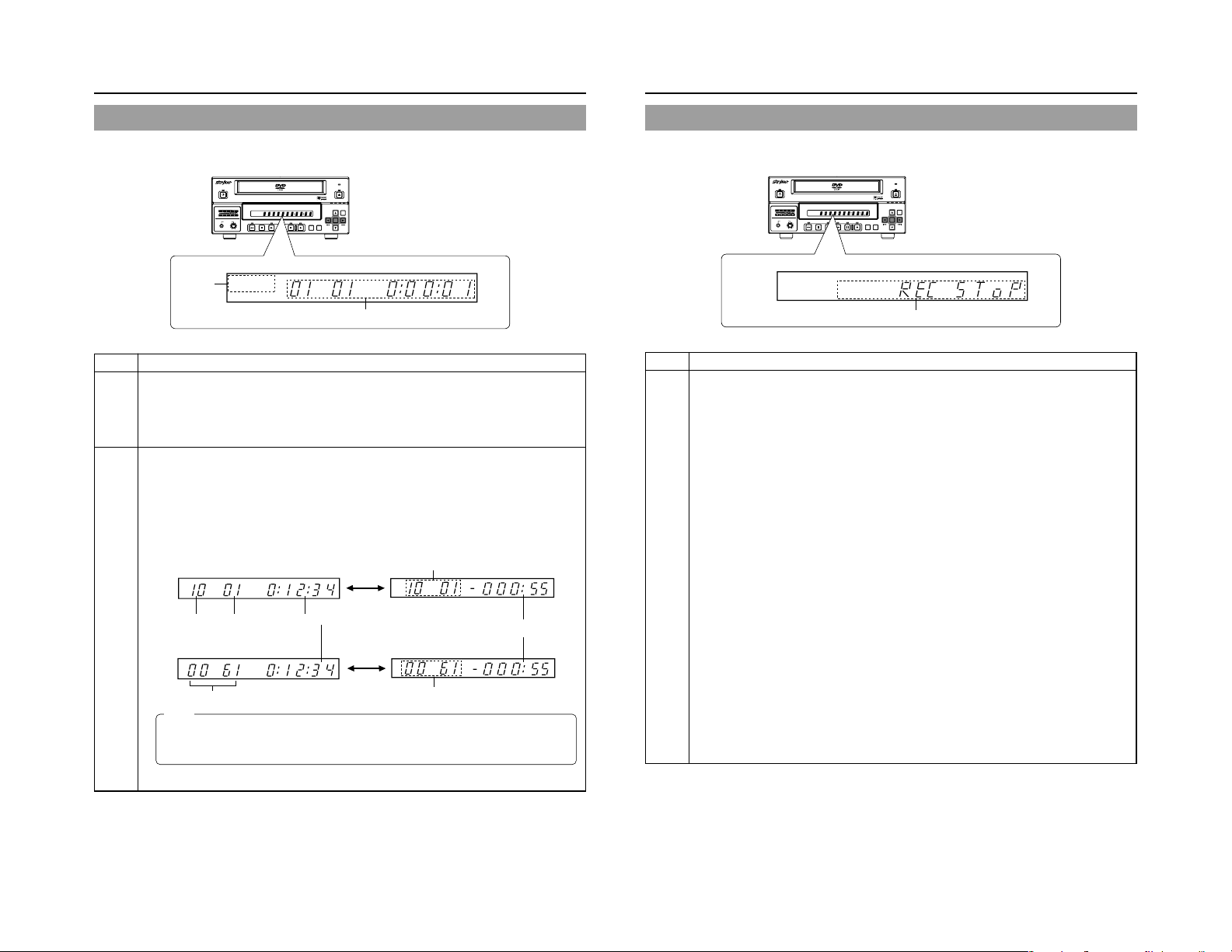
LCD Display and On-Screen Content
LCD Display
The following information and data is presented on the DVD recorder’s LCD display.
BUSY
TITLE
TOP
MENU MENU
OPEN/CLOSE
OPTION DV Y/C LINE
SET
SET UP
CHAP
1
OPERATE
CH1
CH2
PHONES REV
AUDIO
DOLBY DIGITAL
LPCMMPEG
STOP PLAY FWD PAUSE REC
DOLBYDIGITAL
LPCM MPEG
TITLE
CHAPTER
2
No. Description
Encoding format for audio recordings (LPCM / DOLBY DIGITAL / MPEG) …… MPEG can only be selected
1
when in the PAL mode
Recording mode : The encoding format set using AUDIO ENCODE from the RECORDER MENU (1/2) screen is
Playback mode : The encoding format used for audio on the current disc is displayed. This will not be displayed
Information relevant to the current mode.
2
Title number / Chapter number / Index number / Counter
Display details can be selected using the LCD item on the DISPLAY menu screen.
● Displays the title no., chapter no. and remaining time when the LCD item is set to TITLE+CHAPTER.
● Displays the index no. and remaining time when the LCD item is set to INDEX.
Press the SET button to alternate counter display between elapsed time and remaining time.
Remaining Time: Displays the remaining time of the disc (hr: min) during recording and remaining time of the title
during playback.
When the LCD item is set to TITLE+CHAPTER
When the LCD item is set to INDEX
Memo
● The remaining disc and title time depend on the amount of data comprising video, and for this reason, they
●
displayed. This will not be displayed when the AUDIO ENCODE item is set to NO AUDIO.
during playback of a recorded disc with the AUDIO ENCODE item set to NO AUDIO.
Displayed only in recording mode
Disc Remaining Time
(hr: min)
Title No. Chapter No.
SET Button
Total Recording Elapsed Time (hr: min: sec)
SET Button
Index No. (4 digits)
should be taken as being a general indication and not an exact figure. When the remaining time is 1000
hours or more, only the hour units will be displayed in 4 digits.
The SET button is not available while the REC CONTROL panel is displayed.
Displayed only in recording mode
BUSY
TOP
MENU MENU
OPEN/CLOSE
OPTION DV Y/C LINE
SET
CHAP
SET UP
OPERATE
AUDIO
CH1
CH2
PHONES REV
DOLBYDIGITAL
LPCM MPEG
TITLE
CHAPTER
DOLBY DIGITAL
LPCMMPEG
STOP PLAY FWD PAUSE REC
TITLE
2
No. Description
Indication of the current operating mode
2
PLEASE WAIT : The DVD recorder is starting up.
OPERATE OFF : The DVD recorder is preparing to shut down.
NO DISC : The DVD recorder currently contains no disc.
LOADING : A disc is being loaded into the DVD recorder.
DVD-R : The current disc is a non-finalized DVD-R. (Approximately 3 seconds)
DVD-RW : The current disc is a non-finalized DVD-RW. (Approximately 3 seconds)
DVD+R : The current disc is a non-finalized DVD+R. (Approximately 3 seconds)
DVD+RW : The current disc is a non-finalized DVD+RW. (Approximately 3 seconds)
DVD:The current disc is a finalized DVD-R / DVD-RW / DVD+R / DVD+RW. (Approximately 3 seconds)
REC PAUSE : The DVD recorder is switching from Recording mode to Recording Pause mode.
REC STOP : The DVD recorder is switching from Recording mode to Stop mode.
MENU EDIT : A title menu or chapter menu is currently being edited.
EJECT : The current disc is being ejected.
TITLE CLOSE : The DVD recorder is performing title-close processing.
FINALIZE : The DVD recorder is finalizing the disc.
QUICK ERASE : The DVD recorder is erasing data from a DVD-RW disc.
FULL ERASE : The DVD recorder is erasing data from a DVD-RW disc.
INDEX WRITE : Displayed when index is written. (Approximately 3 seconds)
INDEX ERASE : Displayed when index is erased. (Approximately 3 seconds)
TOP MENU : The disc’s top menu is being played.
MENU : A menu is being played.
ENCODE XX : Encoded video is being output. (XX : Encode quality (UXP, XP, SP, EP, DLP, DEP))
RESTORE XX : Displayed when executing disc recovery. XX: Progress (%)
Display of the Setup Menu
Menu items and setting values from the Setup Menu are displayed. (☞ Page 59)
Event messages
Messages relating to incorrect operation and the like are displayed for approximately 3 seconds. (☞ Page 18)
Alarm messages
Alarms are displayed when the DVD recorder cannot obey a command. (☞ Page 19)
14
15
Page 15

LCD Display and On-Screen Content
On-Screen Content
In addition to loop through and playback screens, the monitor connected to the DVD recorder’s VIDEO LINE OUT or Y/C OUT
terminal can display the following.
● Status messages ● Event messages ● Alarm messages ● The Setup Menu (☞ Page 59)
● Recording-operation control screens : REC CONTROL panel (☞ Page 40)
The Setup Menu and a part of the Status messages are displayed on the monitor of the DVI OUT terminal.
Status Messages
The DVD recorder’s setting condition and operation status are indicated by status messages, and these messages are displayed
on loop through or playback screens.
Status Messages of the DVI OUT terminal
REC
REC : While Recording
PAUSE : While Recording Pause
FULL : While Disc is Full
WAIT : While Finalizing
While Recording stop
While Closing title
While Canceling finalization
While Loading
No. Item Description
Title number / Chapter
2
number / Index number /
Counter
Date / Time
3
Use TITLE/CHAPTER / INDEX from the DISPLAY MENU screen to indicate whether or
not this is to be displayed.
OFF : No information is displayed
TITLE+CHAPTER
INDEX+TITLE : Title No. and total elapsed time (hr: min: sec) are displayed.
Use TIME/DATE from the DISPLAY MENU screen to select the way in which the date
and time are displayed.
OFF : No information is displayed.
DATE : Only the date is displayed.
TIME : Only the time is displayed.
TIME+DATE : Both date and time are displayed.
● The date display style can be changed using DATE STYLE from the DISPLAY MENU
screen.
Recording mode : The date and time from the internal clock are displayed.
Playback mode : The date and time of disc recording are displayed. Minute/Second
: Title No., chapter No. and elapsed time of chapter (hr: min: sec) are
displayed.
displays will not be in continuous sequence during playback of
timelaps recorded discs.
Status Messages of the VIDEO LINE or Y/C OUT terminal
The DISPLAY MENU screen can be used to indicate whether or not status messages are to be displayed.
● To display status messages:
Set DISPLAY from the DISPLAY MENU screen to ON.
● The various items of status information for display can be selected.
● If DISPLAY is set to OFF, no status information will be displayed.
6
DVD-RW
000 min
5
FINALIZE
DISC
TITLE
04/05/06
11:20:00
No. Item Description
Operation Mode This area indicates the DVD recorder’s current mode of operation.
1
TITLE 01 00:11:22
CHAPTER
REC
01 00:11:22
Use RECORDER MODE from the DISPLAY MENU screen to indicate whether or not
this is to be displayed.
NO DISC : The DVD recorder currently contains no disc.
EJECT : The current disc is being ejected.
STOP : Stop mode
REC : Recording mode
PAUSE : Recording Pause mode
PLAY : Playback mode
STL : Still mode
FWD >> : Fast-forward playback (low speed)
FWD >>> : Fast-forward playback (high speed)
REV << : Fast-reverse playback (low speed)
REV <<< : Fast-reverse playback (high speed)
SLOW >>> : Slow-forward playback (high speed)
SLOW >> : Slow-forward playback (low speed)
SLOW <<< : Slow-reverse playback (high speed)
SLOW << : Slow-reverse playback (low speed)
LOADING : A disc is being loaded.
RESTORE : Disc recovery in progress. (☞ Page 17)
4
Data relevant to recording:
If the SET UP button is pressed while in Recording mode, the video
encode quality and the audio encoding format will be displayed. If
the SET UP button is then pressed once again, this information is
removed from the screen.
1
23
16
Remaining time
4
REC CONTROL panel
5
DISC STATUS /
6
Index display
Use REMAIN from the DISPLAY MENU screen to indicate whether or not this is to be
displayed.
Recording mode : The amount of video that can still be recorded on the current disc is
Playback mode : Not displayed
* Remaining time is to be used as a general guide, not as an exact figure.
Provided that a recordable disc has been inserted, this panel will be displayed whenever
REC CONTROL from the REMOTE menu screen is set to ON.
The REC CONTROL panel can be used to control recording operations. (☞ Page 43)
● This is displayed even when the DISPLAY item is set to OFF.
When a disc is inserted into the DVD recorder, one of the following disc status is displayed
on the monitor screen (Approximately 3 seconds)
DVD-R : The current disc is a non-finalized DVD-R.
DVD-RW : The current disc is a non-finalized DVD-RW.
DVD+R : The current disc is a non-finalized DVD+R.
DVD+RW : The current disc is a non-finalized DVD+RW.
DVD:The current disc is a finalized DVD-R/RW or DVD+R/RW.
INVALID DISC : The current disc is neither DVD-R/RW or DVD+R/RW.
● The following will be displayed when index is erased. (3 seconds)
INDEX ERASE: Displayed when erasing index.
This is not displayed if DISPLAY from the DISPLAY MENU screen is to OFF.
displayed (in minutes). Only hours will be displayed when the
remaining time is 900 minutes or more.
(Displayed while being inserted.)
Disc Repair Feature
When the power supply is cut off during recording or other operations on this unit, there is a feature to repair the disc.
After the power supply is cut off during recording or other operations, the disc repair (RESTORE) will automatically start when the
power is supplied again.
Cautions
● Do not switch off or plug out the power cord during disc repair.
● The repair might not be possible depending on the disc.
17
Page 16

LCD Display and On-Screen Content
Event Messages ( Only the VIDEO LINE OUT or Y/C OUT terminal)
Event messages are displayed on the DVD recorder’s LCD display and on the monitor when incorrect operations are attempted.
These messages will remain on-screen for approximately 3 seconds.
Monitor screen
TITLE FULL
04/05/04
11:20:00
Monitor message
LCD display
message
INVALID TV INVALId TV A signal of an invalid format has been input.
TITLE FULL TITLE FULL Recording was attempted on a disc already containing 99 titles.
INDEX FULL INdEX FULL An attempt was made to add a index to a title already containing 99 index.
CHAPTER FULL CHAP FULL An attempt was made to add a chapter to a title already containing 99 chapter.
NOT FINALIZE NoT FINAL An attempt was made to eject a disc before it was finalized.
———— A L-xxxx-R Set value is displayed when changing the recording level of analog audio.
———— d L-xxxx-R Set value is displayed when changing the recording level of digital audio.
OPE LOCK oPE LoCK This is displayed when buttons on this unit are operated while the Operation Lock is
DAILY RECORDING
dAILY rEC This is displayed when buttons on this unit are operated during DAILY RECORDING.
TITLE 01 0:11:22
CHAPTER
01 0:11:22
000 min
REC
Event messages:
Displayed when
DISPLAY from
the DISPLAY
MENU screen is
set to ON.
DOLBYDIGITAL
LPCM MPEG
LCD display
Event message
Description
Alternatively, an attempt has been made to play a disc containing signals of an invalid
format.
activated. Operation Lock can be canceled by setting the OPERATION LOCK item
on the SYSTEM MENU (2/2) screen to OFF.
(☞ Page 42)
Alarm Messages ( Only the VIDEO LINE OUT or Y/C OUT terminal)
Alarm messages are displayed on the DVD recorder’s LCD display and on the monitor when the recorder cannot obey a command.
These messages will remain on-screen until the next operation is carried out.
Monitor screen
REC INHIBIT
04/05/04
11:20:00
Monitor message
LCD display
message
INVALID DISC INVALId dISC The current disc is not a DVD-R / DVD-RW or DVD+R / DVD+RW.
NOT SUPPORT NoT SUPPoRT A disc recorded using a different DVD recorder was inserted or played.
DISC
REC INHIBIT REC INH ● Recording was attempted using a disc on which no more data can be recorded.
COPY INHIBIT CoPY INH Recording of a copy-protected signal was attempted.
DISC FULL dISC FULL All remaining space on the disc is used up during recording.
CELL OVER CELL oVER The number of cells for a single title exceeded 255.
OVERHEATING! oVERHEATING Displayed when the internal temperature of the set rises due to fan malfunction, etc.
INVALID SYNC INVALId SYNC This is displayed if recording is discontinued when signals are interrupted and out of
———— ERRoR This is displayed when playback or recording is stopped due to dirt or damage on the
FAN STO P FAN SToP This is displayed when the fan stops.
TITLE 01 0:11:22
CHAPTER
01 0:11:22
000 min
REC
Alarm messages:
Displayed when
DISPLAY from the
DISPLAY MENU
screen is set to
ON.
DOLBYDIGITAL
LPCM MPEG
LCD display
Alarm message
Description
● The current disc is a non-finalized disc to which no more data can be recorded.
This will be displayed when the recording time for a single title is exceeded as a
result of setting ENCODE QUALITY to a low quality, recording content with little
movement, or other similar factors.
In this case, immediately turn off the power and discontinue use. The power will
automatically shut down in about 20 minutes after the OVERHEATING display.
sync during recording.
disc. In this case, either clean the disc or replace it.
18
CAUTION
If alarm messages such as “INVALID DISC” are displayed several times when a disc recorded using this DVD recorder or a
blank disk is inserted, there is a possibility that the disc itself has been damaged. In such a case, the damaged disc should be
replaced with a new one.
If the alarm messages continue to appear after replacing the disc, the problem may lie within the DVD recorder, and in such a
case, you are recommended to contact either the store where this DVD recorder was purchased or your authorized dealer.
19
Page 17

Preparation
Signal Connections
Video signals
Camera control unit
Camera
Analog video signal
IN
FOR SERVICE
Y/C OUT
VIDEO
AUDIO
LINE
Y/C
CH1
INPUT
LEVEL
IN
OUT
+
4dB
-
8dB
Y/C
OUT
CH2
DV IN/OUT
REMOTE
USB
1
FOOT SW
2
USB
Digital video signal
DVI IN
DVI OUT
LINE OUT
POWER
MAIN
IN
DVI
OUT
AC IN
FOOT SW
Monitor
DVI
FOOT SW
● The video signal for input is selected using INPUT SELECT from the INPUT SELECT MENU screen.
● The audio signals for input are selected using INPUT SELECT from the INPUT SELECT MENU screen.
When either DVI, LINE or Y/C is set for INPUT SELECT, the analog audio signals from the AUDIO IN terminals will be selected
for input.
When DV is set for INPUT SELECT, the DV audio signals from the DV IN/OUT terminal will be selected for input.
● Use the following cable as the DV cable.
VC-VDV204 (2m, 4P-4P) from JVC
VC-VDV206 (2m, 4P-6P) from JVC
Monitor
Keyboard
Power Connections
Connect the Power cord (included) to the DVD recorder.
POWER
MAIN
MAIN POWER switch
Power cord
(included)
AC
OPERATE indicator
OPERATE button
OPERATE
CH1
CH2
Turning the Power On
While in Operate Off mode (i.e., the OPERATE indicator
is lit up in orange), press the OPERATE button.
● The power will turn on, the color of the OPERATE indicator
will change to green, and the DVD recorder will become
ready for use. (Operate On mode)
Note
● A per iod of 45 seconds may pass before the DVD recorder
adopts Operate On mode as it prepares for operation.
● A small amount of current will be required by the DVD
recorder when in Operate Off mode.
IN
OUT
AUDIO
PHONES REV
DVI
AC IN
1.
Connect the Power cord (included) to the DVD
recorder’s AC IN terminal.
2.
Connect the power cord (included) into an
electrical outlet.
3.
Set the MAIN POWER switch to ON.
● Po wer will be supplied to the DVD recorder and the
OPERATE indicator will be lit up in green. (Operate On
mode)
● The AC IN MODE item on the SYSTEM MENU (2/2)
screen can be used to specify whether to start up in the
Operate ON or OFF mode when the power switch is turned
ON.
(☞ Page 65)
CAUTION
● Always use the AC cord provided with the DVD recorder.
The use of other power cord should be avoided.
● Do not turn the power off during recording or playback.
In the case of DVD-R / DVD+R discs, failure to observe
this precaution will result in the discs becoming unusable.
In the case of DVD-RW / DVD+RW discs, it will be
necessary to erase all data from the disc and to start
recording again from the beginning.
Turning the Power Off
Stop the DVD recorder.
(It is recommended that you eject the disc at this time.)
1.
Press the OPERATE button.
● The DVD recorder will adopt Operate Off mode and the
color of the OPERATE indicator will change to orange.
2.
If the DVD recorder will not be used for an extended
period of time, set the MAIN POWER switch to OFF.
● When disconnecting the power cord, remove the power
cord from the electrical outlet first.
Notes
● Pressing the OPERATE button will have no effect in
Recording mode or Recording Pause mode.
● Pressing this button also has no effect during finalizing
and erasing.
20
21
Page 18

Preparation
Inserting & Removing Discs
Disc tray
OPERATE
AUDIO
CH1
CH2
PHONES REV
Inserting a Disc
Press the OPERATE button to activate Operate On mode.
1.
Press the OPEN/CLOSE button.
● The disc tray will open automatically.
While the disc tray is open, the OPEN/CLOSE indicator
will be lit up.
2.
Place the disc on the disc tray.
Ensure that the disc is inserted correctly into the tray’s recess
with the printed side facing upward.
● Carefully place the disc in the tray so as not to hit the front
panel.
3.
Press the OPEN/CLOSE button.
● The disc tray will close automatically.
Notes
● When a disc is inserted, information about that disc is
displayed on-screen. (☞ Page 17)
● When either a new DVD-RW / DVD+RW or one that has
been erased on another machine is inserted, quick erase
starts up. (☞ Page 28)
●
When the AUTO CANCEL DISC FINALIZE item on the
DISC menu screen is set to ON, finalization will be
automatically canceled when a DVD-RW/DVD+RW that is
finalized using this unit has been inserted. (☞ Page 62)
TITLE
DOLBY DIGITAL
LPCMMPEG
STOP PLAY FWD PAUSE REC
BUSY
OPEN/CLOSE
OPEN/CLOSE indicator
OPEN/CLOSE button
OPTION DV Y/C LINE
CHAPTER
TOP
MENU MENU
SET UP
SET
Removing a Disc
Stop the DVD recorder.
1.
Press the OPEN/CLOSE button.
● The disc tray will open automatically.
While the disc tray is open, the OPEN/CLOSE indicator
will be lit up.
● If the current disc has not been finalized, the message
“NOT FINALIZE” will appear on both the monitor and LCD
display.
2.
Remove the disc from the disc tray.
Be sure to wait until the disc tray has opened fully before
removing the disc.
3.
Press the OPEN/CLOSE button.
● The disc tray will close automatically.
Notes
● If the DVD recorder is in either Recording mode or
Recording Pause mode, the disc tray will not open when
the OPEN/CLOSE button is pressed.
● Pressing this button also has no effect during finalizing
and erasing.
● When the AUTO FINZALIZE item on the DISC menu
screen is set to ON, finalization will be executed when
ejecting an unfinalized disc. (When the EDIT MENU item
on the DVD MENU screen is set to DISABLE.)
Precautions regarding the disc tray
● Do not push the disc tray as it is opening or closing.
● Do not place objects other than discs on the disc tray.
● Do not press down on the disc tray.
Using a Keyboard
Menu settings, the title and chapter settings, and other DVD recorder settings are carried out from setting screens displayed on the
TV or monitor. In addition, recording operations can also be carried out from similar screens.
Although the DVD recorder’s buttons are used in setting and operation screens, a keyboard can be used as an alternative.
Connections
Connect a USB keyboard to the USB terminal on the back of the DVD recorder.
This DVD recorder has the two USB terminals.
POWER
MAIN
VIDEO
AUDIO
LINE
Y/C
IN
IN
DVI
Attach the provided ferrite core
Attach the ferrite core as shown in the diagram to reduce
umwanted electromagnetic emission.
Attach the ferritec core as shown in the diagram to this
DVD recorder as near as possible.
OUT
FOR SERVICE
AC IN
USB terminal
The provided ferrite core
The wire clamp
Wind the cable once around
the ferrite core.
Procedure
The following functions can be controlled using the keyboard.
Function Front panel Keyboard
Selection of menu t button † key
items or setting 8 button © key
values 6 button ∞ key
Confirmation of SET button Enter key
settings
The entry of names and comments for the title and chapter menus is carried out using the keyboard. (Set KEYBOARD STYLE from
the SYSTEM MENU (1/2) screen in accordance with the keyboard’s input language.)
7 button √ key
Note
Unless otherwise specified, this user’s manual
describes procedures carried out from the DVD
recorder itself.
CH1
INPUT
LEVEL
IN
OUT
+
4dB
-
8dB
Y/C
OUT
CH2
DV IN/OUT
REMOTE
USB
FOOT SW
1
2
22
23
Page 19

Preparation
Setting & Displaying the Date & Time
Use the following procedure to set the internal clock’s date and time. Even when the DVD recorder’s power is turned off, the clock’s
date and time settings are stored using the internal battery.
Note that these settings are used to write the current date and time to a disc being recorded.
The DISPLAY screen can be used to indicate whether or not the date and time are to be displayed on-screen.
BUSY
OPERATE
AUDIO
CH1
CH2
PHONES REV
Setup Menu
DISC
INPUT SELECT
SYSTEM
DVD MENU
RECORDER
REMOTE
DISPLAY
CLOCK ADJUST
NETWORK
EXIT
CLOCK ADJUST MENU screen
CLOCK ADJUST MENU
MENU
DATE
TIME
DATE SETTING
04 / 05 / 04
4504
CLOCK ADJUST MENU
MENU
DATE
TIME
07 :
07 44
CLOCK SETTING
04/05/04
10:00
SET
YEARMONTH DAY
04/05/04
12:00
44
SET
TITLE
DOLBY DIGITAL
LPCMMPEG
CHAPTER
STOP PLAY FWD PAUSE REC
TOP
MENU MENU
Setting the Date and Time
Setting of the date and time is carried out using the CLOCK ADJUST MENU
screen. During this procedure, the monitor connected to the VIDEO LINE OUT
or Y/C OUT terminal is used to monitor the setting of data.
Turn on the power and ensure that the DVD recorder is stopped.
1.
Press the SET UP button to display the Setup Menu.
2.
Open the CLOCK ADJUST MENU screen.
q Use the 6 and 7 buttons to select CLOCK ADJUST. (The currently
selected menu item is displayed as highlighted.)
w Press the SET button to open the CLOCK ADJUST MENU screen.
3.
Set the date and time as required.
q Use the 6 and 7 buttons to select either DATE or TIME. Then press the
SET button.
w Use the t and8 buttons to select the digit to be changed. (The currently
selected digit is displayed as highlighted text.)
e Use the 6 and 7 buttons to change the value of the selected digit.
r Repeat steps w through e to make all of the required settings, and then
press the SET button.
Note
It is not possible to set the time in units of seconds. After setting the
minutes, press the SET button in sync with a time signal.
4.
After completing all of the required settings, return to the Setup
Menu.
To do this, use the 6 or 7 buttons to select MENU and then press the SET
button.
5.
Return to the normal screen display.
● To do this, press the SET UP button
or
● Select EXIT from the Setup Menu and press the SET button.
OPEN/CLOSE
OPTION DV Y/C LINE
SET UP
SET
7 button8 button
6 button
SET UP button
t button
SET button
24
Setting & Displaying the Date & Time (continued)
Displaying the Date and Time
DISPLAY MENU screen
DISPLAY MENU
MENU
DISPLAY
TITLE/CHAPTER/INDEX
RECORDER MODE
TIME/DATE
REMAIN
DATE STYLE
LCD
On-screen display
04/05/06
11:20:00
TIME/DATE
ON
TITLE+CHAPTER
ON
TIME+DATE
ON
MM/DD/YY
TITLE+CHAPTER
TITLE 01 00:11:22
CHAPTER
01 00:11:22
000 min
REC
Use the DISPLAY MENU screen to indicate whether or not the date and time are
to be displayed on-screen and to set a display style. ( Page 72 for details
regarding setting methods.)
DISPLAY MENU Screen Makeup
DISPLAY: This parameter is used to indicate whether or not data is to
TIME/DATE: This parameter is used to set the way in which the date
DATE STYLE: This parameter is used to select the way in which the
be displayed on-screen.
ON : Data will be displayed on-screen. The following parameters can be
used to indicate which data is to be displayed.
OFF : No data is displayed on-screen.
OFF : Neither date or time are displayed.
TIME : Only the time is displayed.
DATE : Only the date is displayed.
TIME + DATE : Both date or time are displayed.
YY/MM/DD : Year, month, day
MM/DD/YY : Month, day, year
DD/MM/YY : Day, month, year
and time are displayed.
date is to be displayed.
To display date and time information on-screen;
Only the date and time information from the VIDEO LINE OUT and Y/C OUT
terminal are displayed on screen.
● Set DISPLAY to ON.
● Set TIME/DATE to anything other than OFF.
Date and time information is displayed as follows.
Mode Displayed information
Recording or Stop The value of the internal clock
Playback The date and time at which the current disc was
recorded.
25
Page 20

Settings & Controls for Recording
DVD Recording
DVD recording is carried out using the following procedure.
Pre-Recording Settings
Preparation of the DVD-R / DVDRW (video mode only) or DVD+R /
DVD+RW.
On-screen settings
Adjustment of audio recording levels.
Selection of styles for the title and
chapter menus
Start of
recording
End of
recording
Start of
recording
End of
recording
Start of
recording
End of
recording
Chapter 1
(chapter mark)
Chapter 2
Title 1
Chapter 3
Chapter 4
(Title closing)
Chapter 1
Title 2
Chapter 2
(Title closing)
Title 3
(Title closing)
● Insert a new DVD-R / DVD-RW (video mode) or DVD+R / DVD+RW or alternatively, a
similar disc that has been recorded on using the DVD recorder.
● If the recording on a DVD-RW / DVD+RW is to be performed once again from the
beginning, erase the disc’s data using ERASE from the DISC MENU screen. (☞ Page 28)
Use the setting screens to select the appropriate recording signal, setup the recording
conditions, and make other necessary settings. (☞ Page 29)
Audio recording levels can be adjusted in one of two different ways. (☞ Page 32)
The title and chapter menus are used during playback of a disc to select the section of
the disc to be viewed. A total of five different display styles have been made available for
these menus, and these can be selected using the DVD MENU screen. In addition, the
DVD recorder also allows you to freely modify these display styles.
(☞ Page 35)
Recording Operations (☞ Page 37)
● The section between the star t of recording using the REC and PLAY buttons
and the end of recording using the STOP button constitutes a single recording
title, and each title is assigned a unique number.
A single disc can contain up to 99 different titles.
● Each title can be separated into a number of different chapters by inserting
chapter marks at the appropriate points. Unique numbers are also assigned
to chapters, and a single title can contain up to 99 different chapters.
● Adding chapters
If the REC button is pressed while recording, chapter mark and index will be
inserted.
In addition, CHAPTER CREATION from the RECORDER MENU (1/2) screen
can also be used to setup the automatic or manual insertion of chapter marks
and index.
● Thumbnails (i.e., the frame at the start of recording) and backgrounds are
automatically created for the title and chapter menus using the style selected
using STYLE from the DVD MENU screen.
If EDIT MENU from the DVD MENU screen is set to ENABLE before the start
of recording, it will be possible to modify the chapter menu’s style and
thumbnails and to insert chapter names and comments whenever recording
is stopped (i.e., whenever title closing is performed).
● Once title closing has been carried out, it will not be possible to modify the
chapter menu.
● The REC CONTROL panel can be used to perform recording operations with
a keyboard. (REC CONTROL from the REMOTE MENU screen must be set
to ON.)
● If EDIT MENU from the DVD MENU screen is set to ENABLE, it will be possible
to modify the title menu’s style and to input title names when the disc is being
finalized.
Preparing a Disc for Recording
This DVD recorder is capable of recording to DVD-R / DVD-RW (in video mode) and DVD+R / DVD+RW.
DVD-R : Only discs that conform with DVD-R Standard 2.0 (video mode) can be used.
DVD-RW : Discs of Version 1.1 or later can be used.
In terms of recording characteristics, DVD-R / DVD-RW (video mode) and DVD+R / DVD+RW differ as follows.
DVD-R / DVD+R : Each disc can be recorded only once. Erasing of data and re-recording are not possible.
DVD-RW (video mode) / DVD+RW: After viewing a disc, all data can be erased and it can be used to record new content.
The condition of the disc being used will dictate the available recording options as follows.
DVD-R
DVD+R
DVD-RW
DVD+RW
● If data has been erased from a disc using a different DVD recorder, it may not be possible to record new content to it using
● New content cannot be recorded to discs that have been finalized.
● Regardless of whether or not finalization has been carried out, it will not be possible to use this DVD recorder to record new
Although Version 1.1 of DVD-RW standards allows the selection of video mode and VR mode for recording, this
DVD recorder performs recording in video mode only.
*Version 1.0 of the DVD-RW standards does not support video-mode recording, and for this reason, the corresponding
discs cannot be used.
Disc condition Recording operations
Blank disc
A disc recorded on using this DVD recorder
but not yet finalized.
Blank disc
A disc recorded on using this DVD recorder
but not yet finalized.
A recorded disc from which data is to be
erased.
Notes
this recorder. To avoid this type of situation, ensure that this DVD recorder is used to erase recorded data.
It is possible to cancel the finalization and add a recording to a DVD-RW / DVD+RW finalized on this machine.
content to a disc that has been recorded on using other devices.
New content can be recorded. A new title is created and recording
starts from that title’s first chapter.
A new title is created in the unused section of the disc, and recording
starts from that title’s first chapter.
New content can be recorded. A new title is created and recording
starts from that title’s first chapter.
A new title is created in the unused section of the disc, and recording
starts from that title’s first chapter.
Erase the recorded data (as described below), and then record
new content.
If additional recording is to be
performed:
Press the OPEN/CLOSE button and
remove the disc.
26
Processing After Recording (☞ Page 43)
If the disc is to be played on this DVD recorder or on a different DVD player:
Finalize the disc.
To do this, select FINALIZE from the DISC MENU screen.
* When a disc has been finalized, it will not be possible to record more content to it or to
modify its menu styles.
27
Page 21

Settings & Controls for Recording
Erasing All Data From a DVD-RW / DVD+RW Disc
DISC menu screen
DISC MENU
MENU
FINALIZE
CANCEL DISC FINALIZATION
AUTO FINALIZE
AUTO CANCEL DISC FINALIZ.
(
)
DISC ERASE
QUICK
DISC ERASE
(
)
FULL
Note
When either a new DVD-RW / DVD+RW
or one that has been erased on another
machine is inserted, quick erase starts up.
CANCEL
CANCEL
OFF
OFF
EXECUTE
CANCEL
1.
Insert the DVD-RW from which data is to be erased.
2.
Press the SET UP button to display the Setup Menu.
3.
Use the 7 and 6 buttons to select DISC item and then press
the SET button.
● The DISC menu screen will appear.
4.
Press the 7 or 6 button, select either the DISC ERASE (QUICK)
item or the DISC ERASE (FULL) item, then press the SET button.
● The setting value list box is displayed.
DISC ERASE (QUICK): Only the disc control area is erased. (Quick Erase)
Compared with Full Erase the time to erase is
shorter.
DISC ERASE (FULL): All areas of the disc are erased. (Full Erase) This
setting is recommended for repeated use of a disc.
5.
Use the 7 and 6 buttons to select EXECUTE from the list and
then press the SET button.
● The erasing of data will begin.
The message “PLEASE WAIT” appears on the monitor.
● When all data has been erased, the message will disappear.
CAUTION
● All of the data recorded to the disc will be erased in this process. Before
starting, therefore, confirm that no important data is stored on this disc.
● Under no circumstances should the power be turned off or the power cord
disconnected while data is being erased.
Canceling the Finalization of a DVD-RW / DVD+RW
When adding an extra recording to a finalized DVD-RW / DVD+RW, cancel the finalization.
DISC menu screen
DISC MENU
MENU
FINALIZE
CANCEL DISC FINALIZATION
AUTO FINALIZE
AUTO CANCEL DISC FINALIZ.
(
)
DISC ERASE
QUICK
DISC ERASE
(
)
FULL
CANCEL
EXECUTE
OFF
OFF
CANCEL
CANCEL
1.
Insert the DVD-RW / DVD+RW whose finalization you want to
cancel.
2.
Press the SET UP button and the set up top menu screen will be
displayed.
3.
Press the 7 or 6 button to select the DISC item, then press the
SET button.
● The DISC menu screen is displayed.
4.
Press the 7 or 6 button, and select the CANCEL DISC
FINALIZATION item, then press the SET button.
● The setting value list box is displayed.
5.
Press the 7 or 6 button, select EXECUTE from the list box,
then press the SET button.
● Cancellation of finalization star ts.
The message “PLEASE WAIT” or “WAIT” appears on the monitor.
● When complete, the message disappears.
Notes
● When canceling finalization the TOP MENU created when finalizing is
deleted.
● Discs finalized on another machine cannot be cancelled.
28
Pre-Recording Settings
Recorder switch settings
Use the AUDIO INPUT LEVEL switch on the DVD recorder’s
rear panel to select the reference input level for analog audio
(i.e., +4 dB or –8 dB).
The following screens are used to make settings relevant to
recording. (Screen setting methods: ☞ Page 59)
● INPUT SELECT MENU screen
This screen is used to select the audio and video signals to
be used. For more details, refer to page 63.
● SYSTEM MENU screen
The SYSTEM MENU screen contains two different pages of
parametes.
SYSTEM MENU (1/2) screen
• SET UP (NTSC only)
This parameter is set when an analog video signal (i.e.,
composite or YC separate) is being input to the DVD recorder.
Specifically, a setting is made to reflect whether or not the
input signal is a setup signal. SETUP should be set to ON if
it is a setup signal, or to OFF if it is not.
• TEST SIGNAL
Set this parameter to ON when the color bar output by the
DVD recorder’s internal signal generator is to be recorded.
SYSTEM MENU (2/2) screen
• TV TYPE Item
For selecting the NTSC or PAL mode.
This unit will be rebooted when settings are changed.
• Y/C TERMINAL MODE
This parameter indicates whether the Y/C IN/OUT terminal’s
specification is S1 or S2. (Specifically, it selects the recording
method for the wide-screen discrimination signal.)
Y/C OUT DC
5.0 — 3.5V 2.4 — 1.0V Other
S1 16 : 9 Squeeze Normal 4 : 3
S2 16 : 9 Squeeze 4 : 3 LETTER Normal 4 : 3
● DVD MENU screen
• EDIT MENU
This parameter indicates whether or not a screen for menu
editing is to be displayed during title closing and finalizing.
• STYLE
This screen is used to select the arrangement and
background style for thumbnails displayed on the top menu.
This DVD recorder can store eight individual style type (i.e.,
TYPE1 through TYPE8), and the most suitable type should
be selected here.
• THUMBNAIL FORM
This parameter selects the method to be used for thumbnail
conversion when recording a wide-screen signal.
•
DISC IN ACTION Item / TITLE END Item / DVD MENU TYPE Item
This is used to set the status of a disc created when finalizing. Set
this before recording to a blank disc. (☞Refer to pages 66 and 67.)
● RECORDER MENU screen
The RECORDER MENU screen contains two different pages
of parameters.
RECORDER MENU (1/2) screen
• CHAPTER CREATION
This parameter indicates whether chapters are to be created
automatically or manually.
• SET INTERVAL
This parameter is set the time interval for automatic chapter
creation and is set in units of minutes.
•AUTO CHAPTER (REC PAUSE) Item
Set whether to automatically insert a chapter when recording
is paused.
• ENCODE QUALITY
This parameter is used to set the quality for encording (or
compressing) video data.
•AUDIO ENCODE
This parameter is used to set the format for encoding (or
compressing) audio data.
For more details regarding the encoding of audio and video,
refer to pages 31.
• TIMELAPSE REC Item
Set this to ON to enable timelaps recording. (☞ Page 41)
•DAILY REC Item
Set this to ON to enable DAILY REC (daily recording).
(☞ Page 42)
RECORDER MENU (2/2) screen
•AUDIO CHANNEL (DV)
This parameter is to be set when recording an audio signal
from the DV IN/OUT terminal.
Specifically, it indicates whether the signals from channels 1
and 2 or from channels 3 and 4 are to be recorded. (Only
with sampling frequency of 32 kHz)
• AUDIO REC VOLUME MODE
This parameter is used to select the method for adjustment
of audio recording levels. Specifically, both channels can be
adjusted while maintaining the same level (BOTH), or each
channel can be adjusted independently (INDEPENDENCE).
For more details regarding methods for the adjustment of
audio recording levels, refer to page 32.
• ASPECT
This parameter is used to set the aspect for recorded video.
(AUTO, 4:3, LETTER, or SQUEEZE)
● REMOTE MENU screen
• REMOTE SELECT
This parameter should be set to OFF when not controlling
the DVD recorder via the DV IN/OUT terminal.
• REC CONTROL
This parameter indicates whether or not the REC CONTROL
panel is to be displayed constantly on-screen when a
recordable disc has been inserted.
Set this to ON when using a keyboard.
• FOOT SW1 Item
Set this to any mode other than OFF when turning ON/OFF
recording using an external switch that is connected to the
FOOT SW1 terminal at the rear of this unit.
• FOOT SW2 Item
Set this to any mode other than OFF when writing chapters
or indexes using an external switch that is connected to the
FOOT SW2 terminal at the rear of this unit.
Please see page 70 for details
29
Page 22

Settings & Controls for Recording
Specifying the Disc Status Created when the Disc was Finalized
It is possible to specify the action when a finalized disc is inserted into this machine or a DVD player, or the operation when
playback of a title is finished. Also, it is possible to select whether to create a title menu (TOP MENU) or chapter menu (MENU)
when finalizing or closing a title. It is necessary to carry out the setting before recording to a blank disc. The setting is carried out
with the DISC IN ACTION Item, TITLE END Item or DVD MENU TYPE Item of the DISC MENU screen.
Set up top menu screen
DISC
INPUT SELECT
SYSTEM
DVD MENU
RECORDER
REMOTE
DISPLAY
CLOCK ADJUST
NETWORK
EXIT
DVD MENU screen
DVD MENU
MENU
EDIT MENU
STYLE
TITLE PATERN
CAPTER PATERN
THUMNAIL FORM
DVD MENU TYPE
DISC IN ACTION
TITLE END
DVD MENU TYPE Item
This is for selecting whether to create a title menu (TOP MENU) or a chapter menu (MENU) when finalizing or closing a title.
DISC IN ACTION Item
This is to set the operation when a finalized disc is inserted into this machine or a DVD player.
TITLE END Item
This is to set the operation when playback of a title is finished.
* Settings cannot be changed after the title is recorded. Setting is possible only when there is no disc inserted or when a blank
disc is inserted. Please see page 67 for details.
DISABLE
TYPE1
1
1
NORMAL
TOP
TITLE
NEXT TITLE
Operation
1.
Display the DVD MENU screen
• Press the SET UP button and the set up top menu screen will be displayed.
• Press either the 6 or 7 button to select the DVD MENU item, then press
the SET button.
2.
Set the DVD MENU menu screen
• With the 6 or 7 buttons, select Item, press the SET button and the setting
value list box will be displayed.
• With the 6 or 7 buttons, select the setting value, press the SET button to
confirm the setting value.
3.
Finish the Setting
Carry out either of the following operations.
• Select the MENU item, press the SET button to return to the set up top
menu screen.
• Press the SET UP button to return to the normal screen.
Setting the Encoding Format for Audio & Video
The setting of encoding formats for audio and video is carried out from the RECORDER MENU (1/2) screen as described below.
BUSY
OPEN/CLOSE
OPTION DV Y/C LINE
SET UP
SET UP button
SET
TOP
MENU MENU
SET button
RECORDER MENU (1/2) screen
RECORDER MENU (1/2)
MENU
CHAPTER CREATION
SET INTERVAL
AUTO CHAPTER (RECPAUSE)
ENCODE QUALITY
TIMELAPSE REC
AUDIO ENCODE
DAILY REC
MANUAL
Every05Min
ON
SP
NO USE
DOLBY DIGITAL
NO USE
Video Encoding
Item Description
ENCODE QUALITY For setting the recording quality. Recording quality and time vary with the set values as follows:
(For a 4.7 GB disc)
Set Value
UXP (NOT DVD VIDEO)
XP
SP
LP
EP
DLP (Double LP)
DEP (Double EP)
* Only UXP, XP or SP can be selected when the AUDIO ENCODE item is set to LPCM.
Setting Encoding Formats
Stop the DVD recorder.
1.
Open the RECORDER MENU (1/2) screen.
• Press the SET UP button to display the Setup Menu.
• Select RECORDER using the 6 and 7 buttons and then press the SET
button.
2.
Make the required settings on the RECORDER MENU (1/2)
screen.
• Select the parameter to be set using the 6 and 7 buttons, and then press
the SET button to display a list of possible settings.
• Select the required setting using the 6 and7 buttons, and then press the
SET button to adopt it.
3.
Complete the setting process.
To do so, carry out one of the following procedures.
• Select MENU and press the SET button to return to the Setup Menu.
• Press the SET UP button to return to the normal screen display.
Recording
Time
40 mins
60 mins
120 mins
180 mins
240 mins
360 mins
480 mins
Picture Quality Upload Size
High
∞
Normal
D1 : NTSC = 720 x 480 dots
:PAL = 720 x 576 dots
√
Low
HalfD1 : NTSC = 352 x 480 dots
√
:PAL = 352 x 576 dots
30
Audio Encoding
AUDIO ENCODE
This parameter is used to set the encoding format for audio data.
NO AUDIO : Do not record audio sound.
LPCM : Linear PCM encoding
DOLBY DIGITAL: Dolby AC3 encoding.
MPEG : MPEG encoding (Effective only when the TV TYPE item from SYSTEM MENU (2/2) screen is set to PAL.)
Note
If the SET UP button is pressed while in Recording mode, the video encode quality and audio encoding format will be
displayed on-screen. Press the SET UP button once again to hide this information.
31
Page 23

Settings & Controls for Recording
Adjusting of Audio Recording Levels
This DVD recorder’s audio recording levels can be adjusted using two different methods, and AUDIO REC VOLUME MODE from
the RECORDER MENU (2/2) screen indicates the method to be used. In addition, it is also possible to return the audio recording
levels to their default settings (i.e., unity gain).
Note: The AUDIO INPUT LEVEL switch on the DVD recorder’s rear panel can be used to select the reference input level for analog
audio (i.e., +4 dB or –8 dB).
Selecting the Adjustment Method
RECORDER MENU (2/2) screen
RECORDER MENU (2/2)
BACK
AUDIO CHANNEL (DV)
AUDIO REC VOLUME MODE
ASPECT
1,2ch † 1,2ch
BOTH
AUTO
Adjusting the Audio Recording Levels
Audio level indicator
Return from setting screens to the normal display.
Recording levels can be adjusted in either Stop or Recording mode. Be sure to monitor the front panel’s audio level indicator as
the levels are being adjusted. Adjust the level so that the LED on the far right does not light.
Adjusting both channels together (BOTH) Adjusting both channels separately (INDEPENDENCE)
To raise the recording level To adjust the Channel 1 level
Press the 6 button while holding the 8 or
t button to raise the audio recording levels
SET SET
for Channel 1 and Channel 2
simultaneously.
To lower the recording level To adjust the Channel 2 level
Press the 7 button while holding the 8 or
t button to lower the audio recording levels
for Channel 1 and Channel 2
simultaneously.
OPERATE
AUDIO
CH1
CH2
PHONES REV
1.
Open the RECORDER MENU (2/2) screen.
To do this, select † button from the RECORDER MENU (1/2) screen and
press the SET button.
2.
Make the required setting using AUDIO REC VOLUME MODE
from the RECORDER MENU (2/2) screen.
BOTH :Audio levels are adjusted while both the CH1/CH2
INDEPENDENCE : The CH1/CH2 are adjusted separately.
TITLE
CHAPTER
DOLBY DIGITAL
LPCMMPEG
STOP PLAY FWD PAUSE REC
are maintained at the same volume.
BUSY
OPEN/CLOSE
OPTION DV Y/C LINE
SET UP
SET
TOP
MENU MENU
SETSET
Buttons used
Press either the 6 or 7 button while
holding the 8 button.
Pressing the 6 button raises the recording
level.
Pressing the 7 button lowers the recording
level.
Press either the 6 or 7 button while
holding the t button.
Pressing the 6 button raises the recording
level.
Pressing the 7 button lowers the recording
level.
Checking the Video Input
Use the monitor connected to the VIDEO LINE OUT or Y/C OUT terminal to confirm that the input video signal is as required.
The following procedure will allow you to monitor the quality at which the video will be recorded to a DVD.
VIDEO LINE OUT terminal
POWER
MAIN
VIDEO
AUDIO
TITLE
CHAPTER
DOLBY DIGITAL
LPCMMPEG
STOP PLAY FWD PAUSE REC
REV
TOP
MENU MENU
REC button
The setting value of the
ENCODE QUALITY is
indicated on the LCD display.
ENCODE XX
UXP, XP, SP, LP,
EP, DLP, DEP
IN
DVI
OUT
OPTION DV Y/C LINE
BUSY
OPEN/CLOSE
SET
LINE
Y/C
IN
FOR SERVICE
AC IN
SET UP
CH1
INPUT
LEVEL
IN
OUT
+
4dB
-
8dB
Y/C
OUT
CH2
DV IN/OUT
REMOTE
USB
FOOT SW
1
2
Monitor screen
Signal Connections
Connect the VIDEO LINE OUT or Y/C OUT terminal to the monitor.
Procedure
Press and hold the REC button for at least 2 seconds while the DVD
recorder is stopped or inserted with no disc. While this button is being
held, input signal encoded/decoded in MPEG will be output via the VIDEO
OUT or Y/C OUT terminal on the rear panel.
● This function allows the quality of the video to be confirmed before recording
to a DVD.
Note
Audio will be muted at this time.
Returning Audio Recording Levels to Default Settings (UNITY MODE)
Press and hold the 8 and tbuttons simultaneously to return the audio recording levels to their default settings (i.e., unity gain).
● Both of the audio recording levels will be fixed at the default setting.
32
33
Page 24

Settings & Controls for Recording
Title & Chapter Menus
This DVD recorder can automatically create title and chapter menus in response to recording operations and can save these to the
disc being recorded.
When the disc is subsequently played, these title and chapter menus can be used to access specific sections of stored video and
audio.
● When recording is stopped using the STOP button or a similar action (i.e., disc closing), a title number and a thumbnail
(corresponding to the frame at the start of recording) will be created to form part of the disc’s title menu. A single disc can contain
up to 99 different titles.
● Similarly, if a chapter mark is inserted during recording, a chapter number and a thumbnail (corresponding to the frame at the
chapter mark) will be created to form part of the title’s chapter menu. Chapter marks are used as targets for skipping during
playback. Each title can contain up to 99 chapters. Indexes are written together with chapter marks. (Please see page 57 for
details on indexes.)
Start of recording
Title menu
Chapter menus
Display Styles
A total of eight different display styles can be used with title and chapter menus. The DVD MENU screen can be used to select the
type of style to be used in the creation of title and chapter menus.
In addition, each of the display styles can be modified as required. (☞ Page 36)
Depending on the style used and the number of menu items, title and chapter menus may extend over more than one page.
Notes
● This DVD recorder can store a total of six different display patterns for title and chapter menus.
At the time of purchase, this DVD recorder will contain five different template files. Any of the stored display patterns can be
selected to change the styles applied to each of the title and chapter menus.
Modifying Chapter Menus
A chapter menu’s display style and thumbnails can be edited at the end of recording (i.e., during title closing); furthermore, titles
and comments for the chapter menu can also be input at this time. (EDIT MENU from the DVD MENU screen must be set to
ENABLE for this to be possible.) (☞ Page 44)
Modifying the Title Menu
The style used for the title menu and the text input for the title name may both be modified before finalizing is carried out. (EDIT
MENU from the DVD MENU screen must be set to ENABLE for this to be possible.) (☞ Page 50)
Notes
● Thumbnail of the title menu will be the top thumbnail of the chapter menu.
● Once a title is closed, it will no longer be possible to modify the chapter menu.
● No modifications whatsoever will be possible when the disc has been finalized.
● When a disc is finalized, its title menu will be used to create the top menu.
● Thumbnail creation method during wide-signal recording can be selected in THUMBNAIL FORM of the DVD MENU screen.
Title 1
Thumbnail Thumbnail
Chapter mark Chapter mark Chapter mark
Recording Recording
Thumbnail Thumbnail Thumbnail Thumbnail Thumbnail
Chapter 1 Chapter 2
End of recording
Chapter 3
Title 2
Chapter 1 Chapter 2
End of recordingStart of recording
Selecting Styles for Title & Chapter Menu
Each recorded DVD contains title and chapter menus that provide information relating to its titles and chapters.
Whenever recording is carried out, title numbers, chapter numbers, and thumbnails are automatically generated in order to create
the title and chapter menus.
Specifically, the frames from the start of individual recordings are used as thumbnails for the title menu.
In a similar way, the frames at which chapter marks have been inserted are used as thumbnails for chapter menus. (These thumbnails
may be modified later on.) The title menu will become the top thumbnail of the chapter menu.
The term “style” is used to refer to a combination of thumbnail characteristics for the title and chapter menus. This DVD recorder can
store eight different style types, and the DVD MENU screen is used to indicate which of these types is to be used.
Making Settings in the DVD MENU screen
DISC
INPUT SELECT
SYSTEM
DVD MENU
RECORDER
REMOTE
DISPLAY
CLOCK ADJUST
NETWORK
EXIT
DVD MENU screen
DVD MENU
MENU
EDIT MENU
STYLE
TITLE PATERN
CAPTER PATERN
THUMNAIL FORM
DVD MENU TYPE
DISC IN ACTION
TITLE END
Setup Menu
STYLE screen
Style types
DISABLE
TYPE1
1
1
NORMAL
TOP
TITLE
NEXT TITLE
1.
Press the SET UP button to display the Setup Menu.
2.
Select DVD MENU from the Setup Menu and then press the SET
button.
● The DVD MENU screen will appear. Within this screen, the STYLE parameter
indicates the style type currently selected for the title and chapter menus.
3.
Confirm the settings for the currently selected style.
Select STYLE and then press the SET button to display the corresponding
STYLE screen.
TITLE PATTERN : The display pattern currently selected for the title
CHAPTER PATTERN : The display pattern currently selected for chapter
4.
Use the cursor buttons (6, 7, t, and 8) to select one of the
eight style types and display the corresponding STYLE screen.
5.
To use a specific style, select the corresponding type number
and then press the SET button.
This type number will then be stored by the DVD recorder.
Following this, the screen’s BACK button will be highlighted. The SET button
can now be pressed to return to the DVD MENU screen.
If BACK is used to exit the STYLE screen without the SET button
being pressed for the newly selected type, the style setting will
not be updated.
Notes
● The STYLE settings for chapter menus can be freely modified until title closing
is carried out. (☞ Page 44)
● The STYLE settings for the title menu can be freely modified until the DVD is
finalized. (☞ Page 50)
● Each style can be freely modified and stored in the DVD recorder’s memory.
In addition, it is also possible to freely select and modify display patterns
(i.e., the number, position, and size of thumbnails in addition to the
background). For more details regarding modification of STYLE, refer to
page 36.
● In certain cases, the frames used for chapter menu thumbnails may differ
slightly from the exact frames at which the corresponding chapter marks
were inserted.
menu. Each display pattern uses different numbers,
positions, and sizes for thumbnails, in addition to
different backgrounds.
menus. Each display pattern uses different numbers,
positions, and sizes for thumbnails, in addition to
different backgrounds.
34
35
Page 25

Settings & Controls for Recording
Changing Styles for Title & Chapter Menus
The DVD MENU screen can be used to change the styles used for displaying title and chapter menus. One of eight different types
of style can be selected for each of the title and chapter menus.
This DVD recorder can also store a total of six different display patterns for title and chapter menus. At the time of purchase, this
DVD recorder will contain five different template files. Any of the stored display patterns can be selected to change the styles
applied to each of the title and chapter menus.
DVD MENU screen
DVD MENU
MENU
EDIT MENU
STYLE
TITLE PATERN
CAPTER PATERN
THUMNAIL FORM
DVD MENU TYPE
DISC IN ACTION
TITLE END
TITLE PATTERN screen
TITLE PATTERN
BACK
TITLE PATTERN
BACK
TITLE PATTERN
BACK
DISABLE
TYPE1
1
1
NORMAL
TOP
TITLE
NEXT TITLE
1.
Open the DVD MENU screen.
This screen allows patterns to be modified for the style indicated by the STYLE
parameter.
TITLE PATTERN : Shows the pattern number for the current title-menu
CHAPTER PATTERN : Shows the pattern number for the current chapter-
When the STYLE parameter’s number setting is changed, the patterns
used for title and chapter menus in the new style will be displayed by
TITLE PATTERN and CHAPTER PATTERN respectively.
2.
Change the display patterns for the title and chapter menus as
required.
1
1
4
For example, let’s change the title menu’s display pattern from 1 to 4.
Select TITLE PATTERN from the DVD MENU screen and press the SET
button.
● The TITLE PATTERN screen will appear.
3.
Use the cursor buttons (t, 8, 6, and 7) to select the fourth
pattern on the TITLE PATTERN screen, and then press the SET
button.
● The title menu’s display pattern changes to No. 4, and the BACK button
becomes highlighted.
4.
With the BACK button highlighted, press the SET button and return
to the DVD MENU screen.
If BACK is used to exit the TITLE PATTERN screen without the SET button being
pressed for the newly selected pattern, the pattern setting will not be updated.
To change the display pattern for chapter menus, select CHAPTER
PATTERN from the DVD MENU screen and then proceed in the same way
as described above.
Note
The TITLE PATTERN screen and CHAPTER PATTERN screen show the
patterns that are currently stored in this DVD recorder.
Display pattern: A combination of thumbnail characteristics (i.e., position,
display style as indicated by the STYLE parameter.
menu display style as indicated by the STYLE
parameter.
quantity, and size) and the type of menu background used.
Recording
Recording Sequence
Use the following sequence as a reference when performing recording.
● Input settings: ☞ Page 63.
● Video and audio quality settings: ☞ Page 31.
● Navigation settings (i.e., DISC IN ACTION and TITLE END/DVD MENU TYPE): ☞ Page 64
REC button + PLAY button
Start of recording
Chapter 1
REC button
Chapter 2
REC button
Chapter 3
PAUSE button*1
Recording Pause
PLAY button or PAUSE button
Resumption of recording
Chapter 4
PAUSE button*1
Recording Pause
STOP button
End of recording
Chapter menu modification possible*2 (☞Page 44)
Title closing
Recording of a new title
Processing time:
30 seconds maximum
Processing time:
several seconds ~ several minutes
Title menu modification possible*2 (☞Page 50)
Index 1
Index 2
Index 3
Title 1
Index 4
36
Finalizing
Processing time:
20 minutes maximum
Playback possible (Other DVD player) *3
*1 It is possible to select whether to automatically insert a chapter mark and index when there is a pause in the recording using the
AUTO CHAPTER (REC PAUSE) item of the RECORDER MENU (1/2) screen.
*2 Title and chapter menu modification will be possible when EDIT MENU from the DVD MENU screen has been set to ENABLE.
*3 It is possible to playback a disc that has been recorded on this machine even before finalizing it.
37
Page 26

Recording
Recording with the Front Panel
This DVD recorder recording operations can be carried out in two different ways — namely, using the buttons provided on the front
panel and using the on-screen REC CONTROL panel. In the latter case, furthermore, recording operations can be performed using
a keyboard. The following section, however, will provide a description of recording using the front panel buttons.
On a DVD, the section of video recorded between the start of recording and pressing of the STOP button to end recording is stored
as a single title, and a unique title number is assigned to each of these sections. A single disc can contain up to 99 different titles.
In addition, each title can be separated into a number of different chapters by inserting chapter marks at the appropriate points, and
each title can contain up to 99 chapters.
Information relating to titles and chapters is stored on a disc in the form of title and chapter menus. When the disc is being played,
therefore, the title and chapter menus can be used to access specific sections of stored video and audio.
LCD display
BUSY
TOP
REC button
OPEN/CLOSE
OPTION DV Y/C LINE
SET
OPEN/CLOSE button
SET UP
OPERATE
AUDIO
CH1
CH2
PHONES REV
STOP button
Monitor display
04/05/06
11:20:00
Title and chapter numbers
Notes
● A maximum of 10 minutes will be
required to complete title closing.
● The remaining time available for
recording on a disc will be displayed
on the monitor. Note that this is to be
used as a general guide, not as an
exact figure. (DISPLAY and REMAIN
from the DISPLAY MENU screen must
both be ON for this figure to be
displayed.)
● During the recording process, the
current title number and chapter
number are displayed on the monitor.
(ONSCREEN will be displayed when
the DISPLAY item is ON and the TITLE/
CHAPTER/INDEX item is set to
TITLE+CHAPTER.)
Remaining time
TITLE 01 00:11:22
CHAPTER
01 00:11:22
000 min
REC
TITLE
DOLBY DIGITAL
LPCMMPEG
PLAY button
CHAPTER
STOP PLAY FWD PAUSE REC
PAUSE button
MENU MENU
Insert a disc that can be recorded on.
1.
With the DVD recorder stopped, make all of the required settings
and adjust the audio recording levels.
2.
Start recording.
This is done by pressing and holding the REC button first, followed the PLAY
button.
3.
Pause recording.
This is done by pressing the PAUSE button.
● The recording pause mode is entered.
When the AUTO CHAPTER (REC PAUSE) item of the RECORDER [1/2]
screen is set to ON, a chapter mark is automatically inserted when the
recording pause mode is entered.
A number of different methods can also be used for the manual or automatic
insertion of chapter marks. (☞ Page 39)
4.
Restart recording.
Press the PLAY or PAUSE button.
● Recording will begin once again and a new chapter will be created in the
current title.
5.
End recording (i.e., close the title)
Press the STOP button when either recording or paused.
● The action of the DVD recorder following the end of recording depends on
the setting of EDIT MENU from the DVD MENU screen.
DISABLE : Recording is ended and the chapter menu is created using
ENABLE : The THUMBNAIL EDIT screen will appear. This screen can be
If additional recording is to be carried out, repeat steps 1through
5
above.
● In such a case, the subsequent recording is stored as a new title.
preset settings (i.e., the title is closed).
used to modify the chapter menu’s display style, to change the
thumbnails used, to input chapter names, and to perform other
similar functions. For more details, refer to page 44.
Recording with the Front Panel (continued)
6.
Note
When recording is stopped or a title is
closed, the message will appear on the
VIDEO LINE OUT, Y/C OUT, or DVI OUT
monitor.
Inserting Chapter Marks Manually or Automatically
RECORDER MENU (1/2) screen
RECORDER MENU (1/2)
MENU
CHAPTER CREATION
SET INTERVAL
AUTO CHAPTER (RECPAUSE)
ENCODE QUALITY
TIMELAPSE REC
AUDIO ENCODE
DAILY REC
MANUAL
Every05Min
ON
SP
NO USE
DOLBY DIGITAL
NO USE
Using the Foot Switch to Perform Recording
Operations such as recording and writing chapter marks (indexes) can be performed using the external switch that is connected to
the foot switch terminal at the rear of this unit.
● Use the FOOT SW1 terminal to turn ON/OFF recording. The FOOT SW1 item on the REMOTE menu screen can be used to
specify whether to use the FOOT SW1 terminal as well as to specify conditions for using the terminal. (☞ Page 70)
● Use the FOOT SW2 terminal to write chapter marks (indexes). The FOOT SW2 item on the REMOTE menu screen can be used
to specify whether to use the FOOT SW2 terminal as well as to specify conditions for using the terminal. (☞ Page 70)
End recording and remove the disc.
Depending on how the disc will be used, one of two different procedures is
implemented at this time.
● If more content will be recorded to the disc using this DVD recorder:
Simply press the OPEN/CLOSE button and remove the disc. (Do not finalize
the disc before it is removed.)
* The AUTO FINALIZE item on the DISC menu screen will have to be set to
OFF.
● If the disc is to be played on a different DVD player:
Finalize the disc, press the OPEN/CLOSE button, and then remove the disc.
For more details regarding finalizing, refer to page 43.
It is possible to insert a chapter mark either manually or automatically.
Indexes are written together with chapter marks.
The actual method to be used is determined by CHAPTER CREATION and
SET INTERVAL from the RECORDER MENU (1/2) screen.
● If chapter marks are to be inserted manually at any point, set CHAPTER
CREATION to MANUAL.
Chapter marks and indexes can then be inserted by pressing the REC button
while recording.
● If chapter marks are to be inserted automatically, first of all set CHAPTER
CREATION to AUTO. Then use SET INTERVAL to set a time (in minutes) for
chapter mark insertion.
The DVD recorder will insert chapter marks and indexes at the corresponding
intervals during recording.
Whether a chapter mark is automatically inser ted or not during a recording
pause is set with the AUTO CHAPTER (REC PAUSE) item.
ON : Inser t a chapter mark and index.
OFF : Do not insert a chapter mark and index.
Notes
● The frame at which a chapter mark is inserted will be used for the
corresponding thumbnail in the chapter menu. When EDIT MENU from
the DVD MENU screen is set to ENABLE, the frames used for thumbnails
can be modified on the THUMBNAIL EDIT screen that appears
automatically at the end of recording.
● Each title can contain up to 99 chapters.
● In certain cases, the frames used for chapter menu thumbnails may differ
slightly from the exact frames at which the corresponding chapter marks
were inserted.
● Indexes can be added or deleted when in the Playback mode.
38
39
Page 27

Recording
Using a Keyboard to Control Recording
Recording operations of this DVD recorder can be carried out using the REC CONTROL panel displayed on the monitor. In
addition, a keyboard can also be used when working with this panel.
REC CONTROL panel is only displayed on the monitor of VIDEO LINE OUT and Y/C OUT terminals. It is not displayed on the
monitor of DVI OUT terminal.
POWER
MAIN
VIDEO
AUDIO
LINE
CH1
INPUT
LEVEL
IN
OUT
+
4dB
8dB
Y/C
Y/C
OUT
IN
IN
DVI
OUT
AC IN
FOR SERVICE
CH2
REMOTE
FOOT SW
DV IN/OUT
1
2
USB
REMOTE MENU screen
REMOTE MENU
MENU
REMOTE SELECT
REC CONTROL
FOOT SW1
FOOT SW2
232C BAUDRATE
232C PROTOCOL TYPE
FINALIZE
DISC
TITLE
04/05/06
11:20:00
OFF
TITLE 01 00:11:22
CHAPTER
01 00:11:22
ON
OFF
OFF
9600
TYPE1
000 min
REC CONTROL panel
Notes
● DISC TITLE from the REC CONTROL
panel can be selected to allow a name
to be input for the disc. This type of
name proves useful when managing
discs using a PC. Note that disc names
are not displayed on the monitor or the
DVD recorder.
Characters allowed for the disc title are
alphanumerical characters and
underscore (_) only. Space and other
symbols may not be used.
● FINALIZE and DISC TITLE from the
REC CONTROL panel cannot be used
while recording.
● The Record (r) button from the REC
CONTROL panel can be activated or
clicked to insert chapter marks (indexes)
and thumbnails during recording.
REC
Signal Connections
Connect a keyboard to the USB terminals on the back of the DVD recorder.
Settings
● If the REC CONTROL panel is to be displayed on-screen, set REC CONTROL
from the REMOTE MENU screen to ON.
This panel will be displayed in Stop, Recording, and Recording Pause mode.
To open the Setup Menu, press the DVD recorder’s SET UP button. Or, press
the ESC key on the keyboard, and the set up menu will be displayed.
Procedure
1.
Start recording.
Keyboard : Use the arrow keys (©, †, ∞, and √) to select Record (r) from
2.
Pause recording.
Keyboard : Use the arrow keys (©, †, ∞, and √) to select Pause (w) from
● The DVD recorder will adopt Recording Pause mode; in addition, a chapter
3.
Restart recording.
Keyboard : Use the arrow keys (©, †, ∞, and √) to select either Record (r)
the REC CONTROL panel, and then press the Enter key.
the REC CONTROL panel, and then press the Enter key.
mark (index) and thumbnail will be inserted at the current position.
or Pause (w) from the REC CONTROL panel, and then press the
Enter key.
Steps 2 and 3 can be repeated to create a single, partitioned title.
4.
End recording (i.e., close the title)
Select Stop (q) from the REC CONTROL panel and press the Enter key.
● The action of the DVD recorder following the end of recording depends on
the setting of EDIT MENU from the DVD MENU screen.
DISABLE : Recording is ended and the chapter menu is created using
ENABLE : The THUMBNAIL EDIT screen will appear. This screen can be
If additional recording is to be carried out, repeat steps 1 through 4 above.
● In such a case, each subsequent recording will be stored as a new title.
5.
End recording and remove the disc.
Depending on how the disc will be used, one of two different procedures
is implemented at this time.
● If more content will be recorded to the disc using this DVD recorder:
Simply press the DVD recorder’s OPEN/CLOSE button and remove the disc.
(Do not finalize the disc before it is removed.)
● If the disc is to be played on a different DVD player:
Use FINALIZE from the REC CONTROL panel to finalize the disc before it is
ejected.
For more details regarding finalizing, refer to page 43.
standard settings (i.e., the title is closed).
used to modify the chapter menu’s display style, to change the
thumbnails used, to input chapter names, and to perform other
similar functions. For more details, refer to page 44.
Timelapse Recording
Timelapse recording allows recording over long hours through intermittent recording. During timelapse recording, audio sound is
not recorded. Specify whether to perform timelapse recording using the TIMELAPSE REC item on the RECORDER MENU (1/2)
screen.
RECORDER MENU (1/2) Screen
RECORDER MENU (1/2)
MENU
CHAPTER CREATION
SET INTERVAL
AUTO CHAPTER (REC PAUSE)
ENCODE QUALITY
REC
TIMELAPSE
AUDIO ENCODE
DAILY REC
TIMELAPSE MODE RECORDING SIZE: --Hour--Min
TL RecTime 1.0 sec / IntervalTime 002 sec
MANUAL
Every05Min
ON
SP
ON
NO AUDIO
NO USE
TIMELAPSE REC Configuration Screen
TL REC TIME
INTERVAL TIME
02
03
secsec
SET
NO USE
Confirm
RECORDER MENU (1/2) Screen
RECORDER MENU (1/2)
MENU
CHAPTER CREATION
SET INTERVAL
AUTO CHAPTER (REC PAUSE)
ENCODE QUALITY
TIMELAPSE
REC
AUDIO ENCODE
DAILY REC
TIMELAPSE MODE RECORDING SIZE: 200Hour 00Min
TL RecTime 2.0 sec / IntervalTime 3 sec
If TIMELAPSE MODE RECORDING
SIZE is displayed as 200Hour, this
means TIMELAPSE recording can be
performed for approximately another
200 hours.
MANUAL
Every05Min
ON
SP
ON
NO AUDIO
NO USE
Timelapse Recording Operation (Reference)
Configuration Example
of TIMELAPSE REC
Configuration Screen
Disc for Timelapse
Recording
Recordable Time: Displayed at bottom of the RECORDER MENU (1/2) screen.
TL REC TIME
Set Value
2 sec
Configuration
1.
Display the RECORDER MENU (1/2) screen.
2.
Set the TIMELAPSE REC item on the RECORDER MENU (1/2)
screen to ON.
● The TIMELAPSE REC configuration screen will be displayed.
* TL REC can be specified only when the ENCODE QUALITY parameter is
set to UXP, XP, SP or LP.
3.
Set accordingly on the TIMELAPSE REC configuration screen.
TL REC TIME : For setting the estimated duration (seconds) of each
INTERVAL TIME
1 Change the set value.
Use the cursor buttons ( / / / ) on the main unit to highlight the 8 or
9 buttons on the configuration screen, followed by pressing the
the main unit.
8:Value increases upon pressing the
9:Value decreases upon pressing the
timelapse recording.
Duration can be specified in units of seconds.
:For setting the estimated time interval (seconds) until the
next recording.
button.
button.
* A setting value is a near value.
2 Confirm set value.
Use the cursor buttons (
button on the configuration screen, followed by pressing the SET button on the
main unit.
/ / / ) on the main unit to highlight the SET
● This confirms the settings and the configuration screen disappears.
● Recordable time and set values of TIMELAPSE REC are displayed at the
bottom of the RECORDER MENU (1/2) screen.
● The AUDIO ENCODE item is automatically set to NO AUDIO.
* Select the NO USE button on the configuration screen and press the SET button
on the main unit to clear the set values.
Performing Timelapse Recording
Timelapse recording starts when normal recording operation is performed.
During timelapse recording, the indicator lamp of the button on the main unit
lights up as follows:
Recording (Time as set for TL REC TIME): REC and PLAY buttons light up.
During Interval (Time as set for INTERVAL TIME): REC button lights up.
Press the STOP button to stop timelapse recording.
To quit the Timelapse Recording mode, set the TIMELAPSE REC item on the
RECORDER MENU (1/2) screen to NO USE.
INTERVAL TIME
Set Value
3 sec
2 sec
3 sec
Duration of one timelapse recording
/ button on
40
41
Page 28

Recording
DAILY REC (Daily Recording)
DAILY REC allows recording to start/end automatically at a designated time on a daily basis.
Specify whether to use the DAILY REC feature using the DAILY REC item on the RECORDER MENU (1/2) screen.
RECORDER MENU (1/2) Screen
RECORDER MENU (1/2)
MENU
CHAPTER CREATION
SET INTERVAL
AUTO CHAPTER (REC PAUSE)
ENCODE QUALITY
TIMELAPSE REC
AUDIO ENCODE
DAILY REC
TIMELAPSE MODE RECORDING SIZE: --Hour--Min
TL RecTime 1.0 sec / IntervalTime 002 sec
MANUAL
Every05Min
ON
SP
ON
NO AUDIO
ON
DAILY REC Configuration Screen
hm
:
END TIME
hm
:
19
00
SET
NO USE
START TIME
08 29
Confirm
RECORDER MENU (1/2) Screen
RECORDER MENU (1/2)
MENU
CHAPTER CREATION
SET INTERVAL
AUTO CHAPTER (REC PAUSE)
ENCODE QUALITY
TIMELAPSE
REC
AUDIO ENCODE
DAILY REC
TIMELAPSE MODE RECORDING SIZE: 200Hour 00Min
TL RecTime 1.0 sec / IntervalTime 002 sec
MANUAL
Every05Min
ON
SP
ON
NO AUDIO
08:29 19:00
Set time
When the main unit is operated during DAILY
REC, a "DAILY RECORDING" and "DAILY REC"
message will be displayed respectively on the
monitor and LCD, and operation will be disabled.
To stop recording, press the STOP button for at
least 3 seconds.
Notes on the DAILY REC Feature
● Set the start time for recording to at least 30 seconds later than the current time when configuration is performed.
● The unit switches to the Record Pause mode approximately 10 seconds before recording starts. DAILY REC will not start if
STOP is executed when in the Record Pause mode. Additionally, recording will not stop at the preset end time if it is started
manually while in the Record Pause mode.
● Recording will be performed as follows when it is started manually at a time before the unit switches automatically to the
Record Pause mode (at least 10 seconds prior to the preset start time).
When a start time is preset, recording will not stop at the preset end time.
When a start time is not preset, recording will stop at the preset end time.
● Recording may be discontinued if DISC FULL or SELL FULL occurs before the preset end time.
● There may be a difference of 1 ~ 3 seconds in the start/end time of recording.
● When recording is set to last for almost 1 full day, do so upon taking into account the time required for REC STOP and TITLE
CLOSE processes. Set the end time and start time for the next recording such that they are at least 10 minutes apart from each
other.
When sufficient interval is not created (as illustrated in the example below), recording on the following day may not be executed.
(Example) Start Time 0:00 End Time 23:59
Configuration
1.
Display the RECORDER MENU (1/2) screen.
2.
Set the DAILY REC item on the RECORDER MENU (1/2) screen to
ON.
● The DAILY REC configuration screen will be displayed.
3.
Set accordingly on the DAILY REC configuration screen.
START TIME : For setting the time to start recording (hr: min).
END TIME : For setting the time to end recording (hr: min).
1 Change the set value.
Use the cursor buttons ( / / / ) on the main unit to highlight the 8 or
9 buttons on the configuration screen, followed by pressing the
the main unit.
8:Value increases upon pressing the
9:Value decreases upon pressing the
2 Confirm set value.
Use the cursor buttons (
button on the configuration screen, followed by pressing the SET button on the
main unit.
button.
button.
/ / / ) on the main unit to highlight the SET
● This confirms the set values and the configuration screen disappears.
● The specified time will be displayed as the set value of the DAILY REC item.
* Select the NO USE button on the configuration screen, followed by pressing the
SET button on the main unit to clear the set values.
Performing DAILY REC
To perform DAILY REC, insert a recordable disc and set it to the Stop mode.
Next, set this unit to the Operate ON mode.
It will switch automatically to the Record Pause mode approximately 10 seconds
before recording starts.
Recording will start automatically upon reaching the start time.
Recording will end automatically upon reaching the end time.
• If the EDIT MENU item on the DVD MENU screen is set to ENABLE, the
Chapter Edit menu screen will appear.
The above operation will be repeated on a daily basis.
To cancel the DAILY REC mode, set the DAILY REC item on the RECORDER
MENU (1/2) screen to NO USE. When the power is turned OFF, the DAILY REC
settings will be cleared and automatically set to NO USE.
/ button on
Finalizing (for Playback on Other DVD Players)
Finalize a disc recorded using this DVD recorder as described below in order to ensure that it can be played on other DVD players.
In the case of DVD-RWs, playback will be possible on DVD players that support video mode.
After finalizing a disc;
● No additional recording will be possible.
● The title menu cannot be changed.
● The titles created before finalizing will be displayed as the top menu.
Finalizing
The process of finalizing can be carried out in two different ways.
● Select DISC MENU and then FINALIZE from the Setup Menu.
● Select FINALIZE on the REC CONTROL panel when this is being used for recording.
Setup Procedure: Insert the disc to be finalized.
1.
If using the Setup Menu:
DISC
MENU
MENU
FINALIZE
CANCEL DISC FINALIZATION
AUTO FINALIZE
AUTO CANCEL DISC FINALIZ.
DISC ERASE (QUICK)
DISC ERASE (FULL)
q Press the SET UP button to
display the Setup Menu, and
EXECUTE
then select DISC.
CANCEL
OFF
w Set FINALIZE from the DISC
OFF
CANCEL
MENU screen to EXECUTE
CANCEL
and then press the SET button.
The screen that will now be displayed depends on the setting of EDIT MENU from the DVD MENU screen.
When DISABLE is set, finalization starts. If this is set to ENABLE, a screen for editing title menus will
● The message “PLEASE WAIT” will be displayed on the monitor during finalizing.
The message “WAIT” will appears on the DVI OUT terminal.
● The message will disappear when finalization has been completed and the
normal screen display will then be restored.
(The REC CONTROL panel will not be displayed.)
Select NO from the confirmation screen to cancel finalizing and return to the
previous screen.
Notes
● A maximum of 20 minutes will be required to complete finalizing.
● When finalizing is carried out, all of the disc’s recorded video and audio are
stored in accordance with the DVD Video Standard; accordingly, this content
can also be replayed as DVD video.
● Although a disc finalized using this DVD recorder may in principle be played
on other DVD players, there is no guarantee that all of its content will be
playable.
● When the AUTO FINALIZE item on the DISC menu screen is set to ON,
finalization will be automatically performed when ejecting the disc. (When
the EDIT MENU item on the DVD MENU screen is set to DISABLE.)
● In the case of a DVD-RW/DVD+RW, it is possible to cancel the finalization
and make an additional recording. (☞ page 28.)
1.
If using the REC CONTROL panel : (Only VIDEO
FINALIZE
DISC
TITLE
04/05/04
11:20:00
appear. Use this screen to confirm that the title menu is as
required, to modify the display style, and to input title
names. (☞ Page 50)
DVD-RW
FINALIZE button
TITLE 01 0:11:22
CHAPTER
01 0:11:22
000 min
LINE OUT or Y/C out terminal)
Select FINALIZE and then press
the keyboard’s Enter key.
REC
42
43
Page 29

Title & Chapter Menu Settings
Changing Chapter Menus (THUMBNAIL EDIT Screen)
This DVD recorder can automatically create title and chapter menus as recording operations are started and stopped.
Title and chapter menus are created using the following.
● Chapter thumbnails : The frames at which chapter marks have been inserted are used as thumbnails.
● Title thumbnails : The frames at the start of individual recordings are used as thumbnails. As a result, a title’s thumbnail is
● Display style : Menus are created using the style set using the DVD MENU screen. (Styles determine factors such as
After chapter menus have been created in this way, it will be possible to modify thumbnails and styles, or to insert new names and
comments.
In specific terms, the editing of chapter menus is carried out using the THUMBNAIL EDIT screen that appears when recording of a
title is ended.
Opening the THUMBNAIL EDIT Screen
DVD MENU Screen
DVD MENU
MENU
EDIT MENU
STYLE
TITLE PATERN
CAPTER PATERN
THUMNAIL FORM
DVD MENU TYPE
DISC IN ACTION
TITLE END
THUMBNAIL EDIT screen
When initially displayed, the THUMBNAIL EDIT screen contains thumbnails for up to six recorded chapters in the order that they
were recorded. The seventh and subsequent thumbnails are displayed on the following pages.
● This initial screen can be used to change a chapter’s thumbnail or to input names and comments.
● Operations on this screen can be carried out using the front panel buttons or a keyboard.
Front panel : Select using the t, 8, 6, and 7 buttons, and confirm the selection using the SET button.
Keyboard : Select using the arrow keys and confirm the selection using the Enter key. The input of names and comments is
This button is used to close a disc’s
titles when editing has been
completed. As such, it should not be
used until all other operations have
been completed.
When title close processing has ended,
the display will return to the E-E screen,
and subsequent editing of chapter
menus will not be possible.
Highlighted item:
The currently selected item is
displayed in highlight.
the same as that of its first chapter.
thumbnail positioning and background)
Set EDIT MENU from the DVD MENU screen to ENABLE.
● The THUMBNAIL EDIT screen will appear automatically whenever moving to
ENABLE
TYPE1
1
1
NORMAL
TOP
TITLE
NEXT TITLE
also carried out using the keyboard.
Stop mode from Recording mode or Recording Pause mode.
Note
If EDIT MENU from the DVD MENU screen is set to DISABLE, the THUMBNAIL
EDIT screen will not be displayed. In such a case, title and chapter menus are
created using preset settings.
Displays the previous page
Displays the next page
THUMBNAIL EDIT
TITLE CLOSE
AAA
DDD
BBB
1
2
EEE
4
5
CCC
FFF
1 - 6
Thumbnail
3
6
Chapter number:
This number is used
during description of
operation. It will not
appear on the actual
screen.
CHAPTER MENU TEXT LOAD TEMP LOAD
Changing & Naming Thumbnails for Chapter Menus
The modification of chapter menu thumbnails and the entry of names and comments are carried out as described below using the
THUMBNAIL EDIT screen.
Changing Thumbnails
THUMBNAIL EDIT screen
THUMBNAIL EDIT
TITLE CLOSE
AAA2BBB3CCC
1
1.
DDD5EEE
4
CHAPTER MENU TEXT LOAD TEMP LOAD
THUMBNAIL EDIT
BACK
2.
PREVIEW
THUMBNAIL EDIT
BACK
3.
PREVIEW
BBB
TEXT INPUT
BBBB
TEXT INPUT
CHAPTER
LENGTH:
5000 sec
2
POSITION:
40/100
CHAPTER
LENGTH:
5000 sec
2
POSITION:
50/100
Checking Thumbnails
THUMBNAIL EDIT
TITLE CLOSE
AAA2BBBB3CCC
1
1.
DDD5EEE6FFF
4
CHAPTER MENU TEXT LOAD TEMP LOAD
THUMBNAIL EDIT
BACK
CHAPTER
LENGTH:
BBB
5000 sec
2
POSITION:
40/100
PREVIEW
2.
TEXT INPUT
1 - 6
1 - 6
For example, let’s change the thumbnail for the second chapter.
1.
Select the second chapter and press the SET button.
● The thumbnail screen for this chapter will be displayed.
The CHAPTER LENGTH item displays the chapter length (sec.).
The denominator of the POSITION item is the range in which the thumbnail
can be changed. The numerator shows the current display position.
2.
Select the thumbnail to be used for the second chapter.
Thumbnails can be selected using the † and © buttons found on this screen.
● If you select † and press the SET button, the image* recorded after the
selected thumbnail will be displayed. Each time the SET button is pressed, a
subsequent image will be displayed. (*Image after 15 frames)
By selecting the †† item and pressing the SET button, the display moves
forward by 10 frames.
● If you select © and press the SET button, the image recorded before the
selected thumbnail will be displayed. Each time the SET button is pressed, a
previous image will be displayed.
By selecting the ©© item and pressing the SET button, the display moves
backward by 10 frames.
3.
Select BACK and press the SET button to change that chapter’s
thumbnail.
THUMBNAIL EDIT
TITLE CLOSE
AAA2BBBB3CCC
1
DDD5EEE6FFF
4
CHAPTER MENU TEXT LOAD TEMP LOAD
● The initial THUMBNAIL EDIT screen is
1 - 6
displayed once again.
The thumbnail for the second chapter will have
changed to that just selected.
* Thumbnail of the title menu will be the top thumbnail of the chapter menu.
Use the following procedure to confirm that thumbnails are as desired by displaying
them in full-screen mode.
For example, let’s look at the thumbnail for the second chapter.
1.
Select the second chapter and press the SET button.
● The thumbnail screen for this chapter will be displayed.
2.
Select PREVIEW and then press the SET button.
● The thumbnail image for this chapter will be displayed in full-screen mode.
3.
Select BACK and press the SET button to return to the THUMBNAIL
EDIT screen.
44
Displays the CHAPTER MENU EDIT screen.
Specifically, this screen is used to check and
change display styles.
Reads title text that has been created using
an external application.
3.
BACK
BBBB
45
Page 30

Title & Chapter Menu Settings
Changing & Naming Thumbnails for Chapter Menus (continued)
Entering Names and Comments for Chapter Menus
THUMBNAIL EDIT
TITLE CLOSE
AAA2BBB3CCC
1.
2.
3.
5.
1
DDD5EEE6FFF
4
CHAPTER MENU TEXT LOAD TEMP LOAD
THUMBNAIL EDIT
BACK
CHAPTER
LENGTH:
AAA
5000 sec
POSITION:
40/100
PREVIEW
TEXT INPUT
THUMBNAIL EDIT
BACK
CHAPTER
LENGTH:
AAA
5000 sec
POSITION:
TITLE INPUT
april
CANCEL
THUMBNAIL EDIT
BACK
CHAPTER
LENGTH:
AAA
5000 sec
april
POSITION:
40/100
PREVIEW
TEXT INPUT
THUMBNAIL EDIT
TITLE CLOSE
BBB CCC
AAA
april
23
DDD5EEE6FFF
4
CHAPTER MENU TEXT LOAD TEMP LOAD
Display Characters
The characters displayed in title and
chapter menus depend on the title
or chapter pattern that has been
selected. A preview allows actual
display characters to be confirmed.
Note that at the time of purchase,
display characters will be as follows.
PATTERN No. Display characters
1 17 x 2 (34)
2 17 x 2 (34)
3 32 x 4 (128)
4 50 (Included title No.)
5 25 (Included title No.)
6—
1 - 6
1 - 6
Use the following procedure to apply names to the thumbnails used in chapter
menus, and also to add comments to be displayed on a chapter menu screen.
Names and comments are entered using a keyboard.
Set KEYBOARD STYLE from the SYSTEM MENU (1/2) screen in accordance
with the keyboard’s input language.
The following description assumes that all operations are carried out by keyboard.
For example, let’s now apply a name to the first chapter.
1.
Use the arrow keys to select the first chapter from the THUMBNAIL
EDIT screen, and then press the Enter key.
● The thumbnail screen for this chapter will be displayed.
2.
Select TEXT INPUT using the arrow keys and then press the Enter
key.
● A box for inputting text will appear.
3.
Enter a name or comment into the text box.
Enter a comment to be displayed on
the chapter menu screen.
TITLE INPUT
april
CANCEL
Notes
● The ¥ mark will become a backslash.
● If text cannot be entered, press the CTRL key (right side) on the keyboard.
4.
After the required text has been entered, press the Enter key.
● The text box will close.
The name just emtered will be applied to the selected chapter.
* The text that has been input will be displayed on the chapter menu screen.
5.
Select BACK and then press the Enter key.
● The initial THUMBNAIL EDIT screen will again be displayed, and the name
or comment will be shown for the first chapter.
Note
THUMBNAIL EDIT
TITLE CLOSE
AAA2BBB3CCC
1
DDD5EEE6FFF
4
CHAPTER MENU TEXT LOAD TEMP LOAD
If you select TEXT LOAD from the THUMBNAIL
EDIT screen and then press the SET button, title
1 - 6
text created using an external application will be
read into the DVD recorder for use as a thumbnail
name.
TEXT LOAD
Enter a name for the chapter
menu thumbnail. (Names can be
up to 20 characters in length.)
Select CANCEL and press the Enter key to
close the text box without applying the name
or comment that has been entered.
46
Changing & Checking Chapter Menu Styles
Although display styles for chapter menus are created using settings from the STYLE item of the DVD MENU screen as described
above, the following procedure can be used to modify these styles at the end of title recording. In addition, it will also be possible at
this time to confirm that chapter menus are as required.
These actions are carried out by selecting and confirming CHAPTER MENU from the THUMBNAIL EDIT screen.
Changing the Display Style
THUMBNAIL EDIT
TITLE CLOSE
BBB CCC
AAA
april
23
DDD5EEE6FFF
4
CHAPTER MENU TEXT LOAD TEMP LOAD
1.
CHAPTER MENU
BACK
PRESET STYLE
2.
CHAPTER MENU PREVIEW
PRESET STYLE MENU screen
PRESET STYLE
BACK
TITLE PATTERN 1
3.
CHAPTER PATTERN
1
1 - 6
TYPE 1
1.
Select CHAPTER MENU from the THUMBNAIL EDIT screen and
press the SET button.
● The CHAPTER MENU EDIT screen will appear.
2.
Select PRESET STYLE from the CHAPTER MENU screen and then
press the SET button.
● The PRESET STYLE MENU screen will appear.
The style number set using the PRESET STYLE parameter will be displayed
in this screen.
3.
To change the display PATTERN;
Select PATTERN and then press the SET button.
Turn to page 36 for details regarding the editing procedure.
* TITLE PATTERN and CHAPTER PATTERN changed here are also reflected in
DVD MENU of the SETUP MENU.
47
Page 31

Title & Chapter Menu Settings
Checking the Chapter Menu Screen
Use the following procedure to see how the chapter menu looks when the selected display style is used.
THUMBNAIL EDIT screen
THUMBNAIL EDIT
TITLE CLOSE
AAA
DDD5EEE6FFF
CHAPTER MENU TEXT LOAD TEMP LOAD
1.
april
4
BBB CCC
23
1 - 6
CHAPTER MENU screen
CHAPTER MENU
BACK
PRESET STYLE
CHAPTER MENU PREVIEW
2.
CHAPTER MENU PREVIEW screen
BACK
4.
01102
The denominator shows the
total number of thumbnails,
and the numerator shows
the number of thumbnails
currently created.
03
03/08
1.
Select CHAPTER MENU from the THUMBNAIL EDIT screen and
press the SET button.
● The CHAPTER MENU screen will appear.
2.
Select CHAPTER MENU PREVIEW from the CHAPTER MENU
screen and press the SET button.
● The CHAPTER MENU PREVIEW screen will appear. Here, it will be possible
to preview the first page of the chapter menu.
3.
Confirm that the other pages are as required.
Select † from the CHAPTER MENU PREVIEW screen and press the SET
button to move to the next page.
Select © and press the SET button to move to the previous page.
†† and ©© can be used in combination with the SET button to skip forward
or back in units of ten pages.
4.
Complete the preview process.
To do this, select BACK from the CHAPTER MENU PREVIEW screen and
press the SET button.
● The CHAPTER MENU screen will reappear.
5.
Select BACK from the CHAPTER MENU screen and press the SET
button to return to the THUMBNAIL EDIT screen.
Notes
● Up to 20 seconds per page will be required to create preview displays.
More time may be required depending on the number of thumbnails per
page.
● During creation of preview displays, jump by selecting the †† button can
only be made to the page being created.
● A maximum of 33 pages can be created for the Chapter Menu.
Ending the Editing of Chapter Menus
Once all of the necessary changes and checks have been made using the THUMBNAIL EDIT screen, title closing must be carried
out.
Please ensure that title closing is performed as the last stage of chapter menu editing.
Even if the chapter menu is to be left unchanged, title closing must be carried out to leave the THUMBNAIL EDIT screen. Note that
when title closing has been completed, chapter menu details will be permanently set.
THUMBNAIL EDIT
TITLE CLOSE
1.
AAA
DDD EEE FFF
CHAPTER MENU TEXT LOAD TEMP LOAD
THUMBNAIL EDIT
TITLE CLOSE
AAA
2.
CHAPTER MENU
BBBB CCC
april
BBBB CCC
april
TITLE CLOSE
NO
YES
TEXT LOAD TEMP LOAD
Select NO and then press
the SET button to close the
confirmation window.
The title will not be closed
in this case.
1.
Select TITLE CLOSE from the THUMBNAIL EDIT screen and press
the SET button.
● A confir mation window will appear.
2.
If you wish to proceed with title closing, select YES and then press
the SET button.
● Title closing will begin. The message “PLEASE WAIT” or “WAIT” will appears
on the monitor during title closing.
When title closing has been completed, the message will disappear.
Notes
● A maximum of 10 minutes will be required to complete title closing.
● If EDIT MENU from the DVD MENU screen is set to DISABLE, title closing
will be carried out automatically whenever recording is ended by, for example,
pressing the STOP button. In such a case, title and chapter menus are created
using preset settings.
48
49
Page 32

Title & Chapter Menu Settings
Changing & Checking Title Menu Styles & Names
If EDIT MENU from the DVD MENU screen is set to ENABLE, the TITLE MENU EDIT screen will be displayed upon disc finalizing.
Using this screen, it will be possible to change the title menu’s display style, to enter title names, and to confirm that the title and
chapter menus are as required.
● Thumbnail of the title menu will be the top thumbnail of the chapter menu.
Opening the TITLE MENU Screen
TITLE MENU screen
TITLE MENU
FINALIZE
PRESET STYLE
TITLE TEXT INPUT
TITLE MENU PREVIEW
EXIT
Changing the Display Style
TITLE MENU screen
TITLE MENU
FINALIZE
PRESET STYLE
1.
TITLE TEXT INPUT
TITLE MENU PREVIEW
EXIT
PRESET STYLE screen
PRESET STYLE
BACK
TITLE PATTERN 1
2.
TYPE 1
Settings
Set EDIT MENU from the DVD MENU screen to ENABLE.
Procedure
The TITLE MENU screen will be displayed when finalizing of the disc is started.
1.
Select PRESET STYLE from the TITLE MENU screen and press
the SET button.
● The PRESET STYLE screen will appear.
2.
To change the display PATTERN;
Select TITLE PATTERN and then press the SET button.
For more details regarding the editing procedure, refer to page 36.
* The TITLE PATTERN changed here is also reflected in DVD MENU of the SETUP
MENU.
Changing & Checking Title Menu Styles & Names (continued)
Checking the Title Menu Screen
TITLE MENU screen
TITLE MENU
FINALIZE
PRESET STYLE
TITLE TEXT INPUT
TITLE MENU PREVIEW
1.
EXIT
TITLE MENU PREVIEW screen
BACK 1
3.
01 02 03
TITLE MENU screen
TITLE MENU
FINALIZE
4.
PRESET STYLE
TITLE TEXT INPUT
TITLE MENU PREVIEW
EXIT
03/08
1.
Select TITLE MENU PREVIEW from the TITLE MENU screen and
press the SET button.
● The TITLE MENU screen will appear.
2.
Confirm that the other pages are as required.
● Select † from the TITLE MENU PREVIEW screen and press the SET button
to move to the next page. Starting with the first page of the title menu, the
display will move forward through the pages each time ¥ is selected and
the SET button is pressed.
● Select © and press the SET button to move to the previous page.
● †† and ©© can be used in combination with the SET button to skip
forward or back in units of ten pages.
Displays the previous page Displays the next page
BACK 1
Thumbnail
Background
3.
Complete the preview process.
To do this, select BACK from the TITLE MENU PREVIEW screen and press
the SET button.
● The TITLE MENU screen will reappear.
4.
If you wish to finalize the disc, select FINALIZE from the TITLE
MENU screen and then press the SET button.
(☞ Page 53)
Notes
● Up to 20 seconds may be required per page to display the PREVIEW screen.
More time may be required depending on the number of thumbnails per
page.
● During creation of preview displays, jump by selecting the †† button can
only be made to the page being created.
● A maximum of 33 pages can be created for the Title Menu.
01 02 03
03/08
Displays the page
number
The denominator
shows the total
number of
thumbnails, and the
numerator shows the
number of thumbnails
currently created.
50
51
Page 33

Title & Chapter Menu Settings
Changing & Checking Title Menu Styles & Names (continued)
Changing Names for the Title Menu
TITLE MENU screen
TITLE MENU
FINALIZE
PRESET STYLE
TITLE TEXT INPUT
1.
TITLE MENU PREVIEW
EXIT
TITLE TEXT INPUT screen
TITLE TEXT INPUT
BACK
AAA BBB CCC
2.
DDD
TEXT LOAD
TITLE TEXT INPUT
BACK
AAA BBB CCC
4.
6.
5.
The characters displayed in title and
chapter menus depend on the title
or chapter pattern that has been
selected. A preview allows actual
display characters to be confirmed.
Note that at the time of purchase,
display characters will be as follows.
TITLE INPUT
august
DDD
CANCEL
TEXT LOAD
TITLE TEXT INPUT
BACK
AAA BBB CCC
august
DDD
TEXT LOAD
Display Characters
PATTERN No. Display characters
1 17 x 2 (34)
2 17 x 2 (34)
3 32 x 4 (128)
4 50 (Included title No.)
5 25 (Included title No.)
6—
1 - 6
1 - 6
1 - 6
Each title will be automatically assigned with a recording date/time and ENCODE
QUALITY.
Use the following procedure to enter manually names for titles in the title menu.
Names and comments are entered using a keyboard.
The following description assumes that all operations are carried out by keyboard.
1.
2.
3.
4.
5.
6.
Set KEYBOARD STYLE from the SYSTEM MENU (1/2) screen in accordance
with the keyboard’s input language.
Select TITLE TEXT INPUT from the TITLE MENU screen and press
the Enter key.
● The TITLE TEXT INPUT screen is displayed.
Use the arrow keys to select the title for which text is to be input.
● The currently selected title is highlighted.
Press the Enter key.
● A box for inputting text will appear.
Change the default name in the text box.
TITLE INPUT
august
CANCEL
Select CANCEL and press the Enter key to
close the text box without applying the
name or comment that has been entered.
Notes
● The ¥ mark will become a backslash.
● If text cannot be entered, press the CTRL key (right side) on the keyboard.
After the required text has been entered, press the Enter key.
● The text box will close.
The name just entered will be applied to the selected title.
Select BACK and then press the Enter key.
● The TITLE MENU screen will reappear.
Note
TITLE TEXT INPUT
BACK
AAA BBB CCC
DDD
TEXT LOAD
If you select TEXT LOAD from the TITLE
1 - 6
MENU screen and then press the SET button,
title text created using an external application
will be read into the DVD recorder for use as
a title name.
TEXT LOAD
Enter a name for the title.
(Names can be up to 20
characters in length.)
Finalizing Discs
TITLE MENU screen
TITLE MENU
FINALIZE
1.
PRESET STYLE
TITLE TEXT INPUT
TITLE MENU PREVIEW
EXIT
Confirmation screen
FINALIZE
2.
YES NO
1.
Select FINALIZE from the TITLE MENU screen and press the SET
button.
● A confir mation window will appear.
2.
Select YES and then press the SET button.
● The disc finalizing process will begin.
The message “PLEASE WAIT” or “WAIT” will appears on the monitor during
finalizing.
When the disc has been finalized, the message will disappear and the E-E screen
will return.
Notes
● A maximum of 20 minutes will be required to complete finalizing.
● When finalizing is carried out, all of the disc’s recorded video and audio are
stored in accordance with the DVD Video Standard; accordingly, this content
can then also be replayed as DVD video.
● Although a disc finalized using this DVD recorder may in principle be played
on other DVD players, there is no guarantee that all of its content will be
playable.
● The action to be taken by this DVD recorder when a finalized disc is inserted
or when playback of a title has ended is specified by DISC IN ACTION and
TITLE END respectively from the DVD MENU screen.
● Select EXIT from the TITLE MENU screen and then press the SET button to
return to the E-E screen without finalizing the disc.
52
53
Page 34

Playback
Playing Back a Disc
It is possible to playback a disc recorded on this DVD recorder.
Playback operation may vary according to whether finalization has been performed.
Playing Back a Disc before Finalizing
Operation
BUSY
TOP
MENU MENU
OPEN/CLOSE
OPTION DV Y/C LINE
SET UP
SET
TITLE
CHAPTER
DOLBY DIGITAL
LPCMMPEG
STOP PLAY FWD PAUSE REC
1.
Insert the disc.
2.
Play the disc.
Press the PLAY button.
● The final title is played.
3.
Select still mode.
Press the PAUSE button.
● The machine enters still mode.
● If the PAUSE button is then pressed again in Still mode, the DVD
recorder will advance playback by a single frame.
4.
Restart the play.
Press the PLAY button.
Upon reaching a title end, it will automatically jump to the next title
and play back all titles.
When disc end is reached it will automatically enter stop mode.
The stop position will return to the beginning of the last title.
5.
To manually stop playback press the STOP button.
When the STOP button is pressed, the stop position will be registered
and the next playback will start from the same position. (Resume feature)
BUSY
OPEN/CLOSE
OPTION DV Y/C LINE
SET UP
SET
TOP
MENU MENU
Cursor buttons
OPERATE
AUDIO
CH1
CH2
PHONES REV
DOLBY DIGITAL
LPCMMPEG
STOP button
TITLE
CHAPTER
STOP PLAY FWD PAUSE REC
PAUSE button
PLAY button
Clearing Resume Data
● When the PLAYBACK&232C TYPE item on
the SYSTEM MENU (1/2) screen is set to
DVD, resume data will be cleared and the stop
position will return to the beginning of the last
title if the STOP button is pressed when in
the Stop mode.
● When the PLAYBACK&232C TYPE item is set
to VTR, resume data will not be cleared even
if the STOP button is pressed when in the
Stop mode.
● Resume data will be cleared upon ejecting
the disc.
Playing Back a Finalized Disc
When a disc is finalized, its title menu will be used to create the top menu.
The action taken by this DVD recorder when a disc it has finalized is inserted or when playback of a title has ended will depend on
the settings of DISC IN ACTION and TITLE END as set on the DVD MENU screen during recording.
* Playback may not proceed smoothly with discs recorded using different devices, regardless of whether or not they have been finalized.
OPERATE
AUDIO
CH1
CH2
PHONES REV
DISC IN ACTION setting made during recording
MENU TITLE
The title menu (TOP MENU) will appear
2.
Select the number of the title to be played.
Use the t, 8,7, and 6 buttons to select the title number
for playback.
3.
Press the SET button to begin playback.
4.
Set to Still mode.
This is done by pressing the PAUSE button.
● The DVD recorder enters Still mode.
● If the PAUSE button is then pressed again in Still mode, the DVD recorder will advance playback by a single frame.
5.
Restart playback.
Press the PLAY button.
The DVD recorder will behave as follows when title playback has ended.
These actions will depend on the setting made for TITLE END from the DVD MENU screen during recording.
Playback starts automatically from the first title.
TITLE END item setting during recording
Set to MENU Set to REPEAT Set to STOP Set to NEXT TITLE
Enters stop mode and the title
menu (TOP MENU) is displayed.
6.
Stop playback.
This is done by pressing the STOP button.
● The DVD recorder enters Stop mode.
● When the STOP button is pressed, the stop position will be registered and the next playback will start from the same position.
(Resume feature)
Clearing Resume Data
● Resume data will be cleared upon ejecting the disc.
Repeats playback within the
title.
Enters the stop mode. The title
menu (TOP MENU) is not
displayed.
Stops at the beginning of the
first title.
Next title is played. When
playback of the final title
finished, the first title is played.
(Disc repeat playback)
A Disc Set with No Menu
If a disc with DVD MENU TYPE item of the DVD MENU screen set to NONE is inserted, the title 1 will automatically play.
When the end of the title is reached the next title will be played.
Precaution regarding the playback
● Dur ing playback of a disc, if the input setting is DV then the sound can be delayed. In this case, change the input setting to LINE
or Y/C.
● If the disc is dir ty or damaged good playback may not be possible. In this case either clean the disc or change it.
● When playing back an unfinalized disc containing mixed data such as screen aspect ratio of 4:3, squeezed, and letterbox
format or a menuless disc, the wide information is not always correctly output.
PAUSE
STOP
1.
Insert a disc.
Depending upon the DISC IN ACTION item settings of the DVD MENU screen during recording, the operation will differ.
Operate in accordance with the table below.
PLAY button
SET button
54
55
Page 35

Playback
Fast & Slow Playback
BUSY
OPERATE
AUDIO
CH1
CH2
PHONES REV
TITLE
DOLBY DIGITAL
LPCMMPEG
CHAPTER
STOP PLAY FWD PAUSE REC
FWD buttonREV button
TOP
MENU MENU
OPEN/CLOSE
OPTION DV Y/C LINE
SET UP
SET
Fast-Forward & Fast-Reverse Play Slow-Forward & Slow-Reverse Play
Fast-forwarding
● Press the FWD button during playback to start fast-forward
play.
If the FWD button is pressed during fast-forward playback,
the machine toggles between fast- and slow-forward
playback.
Fast-reversing
● Press the REV button during playback to start fast-reverse
play.
If the REV button is pressed during fast-reverse playback,
the machine toggles between fast- and slow-reverse
playback.
Note
The DVD recorder can be returned to Playback mode during fast-forward, fast-reverse, slow-forward, or slow-reverse play by
pressing the PLAY button. Still mode can be activated by pressing the PAUSE button. Stop mode is activated by pressing the
STOP button.
Slow-forwarding
● Press the FWD button in Still mode to start slow-forward
play.
If the FWD button is pressed during slow-forward playback,
each time it is pressed the slow-forward playback speed
changes from HIGH (>>>) † LOW (>>) † HIGH (>>>).
Slow-reversing
● Press the REV button in Still mode to start slow-reverse
play.
If the REV button is pressed during slow-reverse playback,
each time it is pressed the slow-reverse playback speed
changes from HIGH (<<<) † LOW (<<) † HIGH (<<<).
Playing the Previous or Next Chapter
Press the t button while the DVD recorder is playing to move playback to the
start of the next chapter.
Press the 8 button while the DVD recorder is playing to move playback to the
start of the current chapter.
When the 8 button is pressed within 1 second of a chapter mark, playback
from the beginning of the previous chapter starts.
* The t button is deactivated during playback of the final chapter.
TOP
MENU MENU
OPTION DV Y/C LINE
8 button
SET UP
SET
t button
Playing the Previous or Next Titles
TOP
MENU MENU
OPTION DV Y/C LINE
SET UP
SET
6 button
7 button
During playback, press the 6 button and the next title will be played.
During playback, press the 7 button and previous title will be played.
* During playback of the first title the 7 button is ineffective.
During playback of the final title the 6 button is ineffective.
Index Writing and Index Search
Indexes are used to locate the beginning of specific positions when in the Playback mode. (Index search)
Viewing of index information (index No. and counter data) and index search can be performed on the INDEX MANAGER screen.
Writing Index
Chapter points registered during the Recording mode are used as index values.
Additionally, indexes can also be written to any position when in the Playback mode. Indexes can only be written for unfinalized
discs.
1.
Play back an unfinalized disc.
2.
Select a position and press the REC button accordingly.
● Index will be written to the disc. When doing so, an "INDEX WRITE" message will be displayed on the panel of the main unit.
Notes
● Up to 99 indexes can be written for each title.
● When the FOOT SW2 item on the REMOTE menu screen is set to any mode other than OFF, indexes can be written via
operation of the switch that is connected to the FOOT SW2 terminal of this unit.
Performing Index Search and Erasing Indexes
Index search and erasing of indexes can be performed upon starting up the INDEX MANAGER screen.
1.
Starting up the INDEX MANAGER screen.
Press the SET UP button on the front panel when in the Playback mode (PLAY or STILL mode).
● The INDEX MANAGER screen will be displayed on the monitor.
* The INDEX MANAGER screen will not be displayed if the Top Menu or Menu of a finalized disc is currently displayed.
Title Selection Buttons
INDEX LIST Scroll Buttons
6:
For scrolling the index
No. at the topmost part
of the INDEX LIST in the
descending direction.
7:
For scrolling the index
No. at the bottommost
part of the INDEX LIST in
the ascending direction.
:Move to the previous title
:Move 10 titles backwards
Title No
Title No. Display Area
Displays the selected title No..
INDEX MANAGER
01
Index No Counter Data
0001:
00:05:00:00
0002:
00:05:00:01
0003:
00:05:00:02
0004:
00:05:00:03
0005:
00:05:00:04
0006:
00:05:00:05
0007:
00:05:00:06
0008:
00:05:00:07
0009:
00:05:00:08
0010:
00:05:00:09
INDEX LIST
Displays index value as accumulated from Title 1.
When the PLAYBACK&232C TYPE item on the
SYSTEM MENU (1/2) screen is set to DVD, an
indexes of a selected title will be displayed.
☞
Page 64)
(
Title Selection Buttons
:Move to the next title
:Move 10 titles forward
0001
PLAY
ERASE
ALL ERS
Index No. Display Area
Displays the selected index No..
For searching and playing
back a selected index.
For erasing a selected index.
For erasing all indexes in
a selected title.
56
57
Page 36

Playback
Setup Menu
Index Writing and Index Search (continued)
2.
Selecting an index to search or erase.
Upon starting up the INDEX MANAGER screen, the title and index of the point for which its screen is called up will be selected.
When selecting a title No.
q Press the cursor buttons (
INDEX MANAGER screen.
w Press the SET button on the main unit to select the title No.. The title No. changes each time the SET button is pressed. The
selected title No. will be displayed on the Title No. Display Area.
When selecting an index No.
q Press the cursor buttons (
w Press the SET button on the main unit and the highlighted index No. will be selected.
● The selected index No. will be displayed on the Index No. Display Area.
* To scroll the INDEX LIST automatically, highlight the 6 / 7 buttons on the INDEX MANAGER screen, followed by pressing
the SET button on the main unit.
3.
Performing index search
q Press the cursor buttons ( / / / ) on the main unit to highlight the PLAY button on the INDEX MANAGER screen.
w Press the SET button on the main unit to execute index search.
● The unit will automatically search for the index position and play back accordingly.
● The INDEX MANAGER screen disappears.
4.
Erasing indexes
Select an index according to the procedure in 2. above.
q Press the cursor buttons (
w Press the SET button on the main unit to display the confirmation dialog box.
e Once erase is executed via the confirmation dialog box, the selected index will be deleted.
● When doing so, an "INDEX ERASE" message will be displayed on the panel of the main unit as well as onscreen for
approximately 3 seconds.
● INDEX LIST on the INDEX MANAGER screen will be sorted.
When erasing all indexes in a title,
there is no need to select the indexes.
q Select the ALL ERS button on the INDEX MANAGER screen, followed by pressing the SET button on the main unit.
● A confirmation dialog box will be displayed.
w Once erase is executed via the confirmation dialog box, all indexes of the selected titles will be deleted.
5.
Quitting the INDEX MANAGER screen
Press the SET UP button on the main unit.
Note
Arrow keys (
on the main unit respectively.
/ / / ) and the Enter key on the keyboard can also be used as a substitute to the cursor and SET buttons
/ / / ) on the main unit to highlight the title selection buttons ( / / / ) on the
/ / / ) on the main unit to move within the INDEX LIST and highlight a specific index No..
/ / / ) on the main unit to highlight the ERASE button on the INDEX MANAGER screen.
Setting the Setup Menu
Settings made in the setup menus are stored in this DVD recorder’s internal memory and will be retained even when the power is
turned off. It is also possible to return to default settings whenever so required.
In addition to the buttons on the front panel, a keyboard can also be used to perform operations on these menus. The following
section, however, will describe operations performed using the front panel buttons.
Keyboard : Select using the arrow keys (∞ and √), and confirm the selection using the Enter key.
BUSY
Cursor buttons
OPEN/CLOSE
(6, 7, 8 and t)
OPTION DV Y/C LINE
SET UP
SET UP button
SET
TOP
MENU MENU
SET button
Setup Menu
DISC
INPUT SELECT
SYSTEM
DVD MENU
RECORDER
REMOTE
DISPLAY
CLOCK ADJUST
NETWORK
EXIT
RECORDER MENU (1/2) screen
RECORDER MENU (1/2)
MENU
CHAPTER CREATION
SET INTERVAL
AUTO CHAPTER (RECPAUSE)
ENCODE QUALITY
TIMELAPSE REC
AUDIO ENCODE
DAILY REC
RECORDER MENU (1/2)
MENU
CHAPTER CREATION
SET INTERVAL
AUTO CHAPTER (RECPAUSE)
ENCODE QUALITY
TIMELAPSE REC
AUDIO ENCODE
DAILY REC
MANUAL
Every05Min
ON
SP
NO USE
DOLBY DIGITAL
NO USE
MANUAL
AUTO
SP
NO USE
DOLBY DIGITAL
NO USE
Settings
Setup menu operations are carried out while monitoring the display on the monitor
connected to the DVI OUT, VIDEO LINE OUT or Y/C OUT terminal. In addition,
setup menu content also appears on the LCD display.
Stop the DVD recorder.
1.
Open the Setup Menu screen.
To do this, press the SET UP button
2.
Open the setup menu in which settings are to be modified.
q Use the 6 and 7 buttons to select the required screen.
w Press the SET button
* The EXIT option can be selected to return to the normal screen display.
3.
Make the required settings in the setup menu.
q Use the 6 and 7 buttons to select the parameter to be set.
w Press the SET button
● A list of setting values will appear.
e Use the 6 and 7 buttons to select the required value from the list and then
press the SET button.
● The setting value will be modified accordingly.
r Repeat steps q through e until all of the required settings have been
made.
To return to the Setup Menu, select MENU and press the SET button.
To move to the next menu screen, select the † button at the top of the current
screen and press the SET button.
To return to the original menu screen, select either MENU or BACK and press
the SET button.
4.
Use either of the following methods to return to the normal screen
display.
Press the SET UP button.
or
Select EXIT from the Setup Menu and press the SET button.
58
Restoring to Default Settings
SYSTEM MENU screen
SYSTEM MENU (1/2)
MENU
SETUP
TEST SIGNAL
FACTORY SETTING
KEYBOARD STYLE
PLAYBACK & 232C TYPE
TOTAL RECORDING TIME
OFF
OFF
EXECUTE
ENGLISH
DVD
5 Hour 30 Min
Setting list
All settings from the various setup menus can be returned to the corresponding
default settings by setting FACTORY SETTING from the SYSTEM MENU screen
to EXECUTE and by then pressing the SET button.
* The current set values for the TV TYPE item on the SYSTEM MENU (2/2) screen
will not be erased.
59
Page 37

Setup Menu
Setup Menu Configuration
The Setup Menu screen is displayed on both the monitor and LCD display. As shown below, this screen is used to access this DVD
recorder’s setup menus.
Setup Menu (☞ Page 61 )
DISC
INPUT SELECT
SYSTEM
DVD MENU
RECORDER
REMOTE
DISPLAY
CLOCK ADJUST
NETWORK
EXIT
DISC MENU screen (☞ Page 62)
DISC MENU
MENU
FINALIZE
CANCEL DISC FINALIZATION
AUTO FINALIZE
AUTO CANCEL DISC FINALIZ.
(
DISC ERASE
QUICK
DISC ERASE
(
FULL
SYSTEM MENU (1/2) screen
(☞ Page 63)
SYSTEM MENU (1/2)
MENU
SETUP
TEST SIGNAL
FACTORY SETTING
KEYBOARD STYLE
PLAYBACK & 232C TYPE
TOTAL RECORDING TIME
RECORER MENU (1/2) screen
(☞ Page 68)
RECORDER MENU (1/2)
MENU
CHAPTER CREATION
SET INTERVAL
AUTO CHAPTER (REC PAUSE)
ENCODE QUALITY
TIMELAPSE REC
AUDIO ENCODE
DAILY REC
CANCEL
CANCEL
OFF
OFF
)
CANCEL
)
CANCEL
OFF
OFF
CANCEL
ENGLISH
VTR
5 Hour 30 Min
MANUAL
Every05Min
ON
SP
NO USE
DOLBY DIGITAL
NO USE
DISPLAY MENU screen (☞ Page 72)
DISPLAY MENU
MENU
DISPLAY
TITLE/CHAPTER/INDEX
RECORDER MODE
TIME/DATE
REMAIN
DATE STYLE
LCD
NETWORK MENU screen (☞ Page 73)
NETWORK MENU
MENU
HOST NAME
IP ADDRESS SETTING
IP ADDRESS
SUBNET MASK
DEFAULT GATEWAY
ON
OFF
OFF
OFF
OFF
MM/DD/YY
TITLE+CHAPTER
dvd
STATIC
192.168.0.2
255..255.255.0
192.168.0.254
INPUT SELECT MENU screen
(☞ Page 63)
INPUT SELECT MENU
MENU
INPUT SELECT
SYSTEM MENU (2/2) screen
(☞ Page 65)
SYSTEM MENU (2/2)
BACK
AC IN MODE
TV TYPE
VBID OUT(WIDE)
Y/C TERMINAL MODE
OPERATION LOCK
DVD MENU screen (☞ Page 66)
DVD MENU
MENU
EDIT MENU
STYLE
TITLE PATTERN
CHAPTER PATTERN
THUMBNAIL FORM
DVD MENU TYPE
DISC IN ACTION
TITLE END
RECORER MENU (2/2) screen
(☞ Page 69)
RECORDER MENU (2/2)
BACK
AUDIO CHANNEL (DV)
AUDIO REC VOLUME MODE
ASPECT
REMOTE MENU screen (☞ Page 70)
REMOTE MENU
MENU
REMOTE SELECT
REC CONTROL
FOOT SW1
FOOT SW2
232C BAUDRATE
232C PROTOCOL TYPE
CLOCK ADJUST MENU screen
(☞ Page 73)
CLOCK ADJUST MENU
MENU
DATE
TIME
DVI
ON
NTSC
OFF
S1
OFF
DISABLE
TYPE1
1
1
NORMAL
TOP
TITLE
NEXT TITLE
1,2ch † 1,2ch
BOTH
AUTO
OFF
OFF
LOW EDGE
LOW EDGE
9600
TYPE1
04/12/04
10:00
Setup Menus
The following table identifies and describes the parameters that may be set using the Setup Menus.
Top half : Appearance on monitor screen
Bottom half : Appearance on LCD display
Option Description
DISC
dISC
INPUT SELECT
INPUT SEL
SYSTEM
SYSTEM
DVD MENU
dVd MENU
RECORDER
RECoRdER
REMOTE
REMoTE
DISPLAY
dISPLAY
CLOCK ADJUST
CLoCK
NETWORK
NETWoRK
EXIT
EXIT
This button opens a menu that allows settings to be made for finalizing and other similar disc processes.
This button opens a menu that allows input audio and video signals to be selected.
This button opens a SYSTEM MENU screen containing two different pages of parameters.
This button opens a menu that allows settings to be made for the DVD recorder itself.
This button opens a menu that allows settings to be made for title-menu and chapter-menu display styles.
This buttons opens a RECORDER MENU screen containing two different pages of parameters.
The RECORDER MENU (1/2) screen allows settings to be made for the chapter creation method and the
encoding of audio and video.
The RECORDER MENU (2/2) screen allows the settings required for recording to be made.
This button opens a menu that allows settings to be made for remote operations via the DVD recorder’s
FOOT SW, RS-232C or DV terminal. In addition, this menu also allows indication of whether or not the
REC CONTROL panel is to be displayed.
This button opens a menu that allows settings to be made for the display of status and alarm information
on the TV or monitor screen.
This button opens a menu that allows setting of the internal clock’s date and time.
This button opens a menu that allows network settings to be made for FOR SERVICE terminal usage.
This button is selected to return to the normal screen display.
60
MAC ADDRESS
99.99.99.99.99
61
Page 38

Setup Menu
DISC MENU Screen
The following table identifies and describes the parameters that may be set using the DISC MENU screen.
Top half : Appearance on monitor screen
Bottom half : Appearance on LCD display
[ ] : Default setting
Parameter Possible settings Description
FINALIZE [CANCEL]
FINAL [CAN]
CANCEL DISC [CANCEL]
FINALIZATION EXECUTE
CAN FIN [CAN]
AUTO FINALIZE [OFF]
AFINAL [oFF]
AUTO CANCEL [OFF]
DISC FINALIZ. ON
ACAN FI [oFF]
DISC ERASE [CANCEL]
(QUICK) EXECUTE
q ERASE [CAN]
DISC ERASE [CANCEL]
(FULL) EXECUTE
F ERASE [CAN]
MENU
MENU
EXECUTE
EXE
EXE
ON
oN
oN
EXE
EXE
This parameter is selected to finalize a disc to be finalized. If a disc recorded using
this DVD recorder is to be played on a DVD player, it must first be finalized. Once
finalizing has been carried out, no addition recordings can be made on the disc.
CANCEL : Finalizing is not to be carried out.
EXECUTE : Finalizing is to be carried out.
Select whether to cancel the finalization of a finalized DVD-RW / DVD+RW. To add a
recording to a finalized DVD-RW / DVD+RW set to EXECUTE. A DVD-RW / DVD+RW
finalized on another machine cannot be canceled.
CANCEL : Do not cancel the finalization.
EXECUTE : Cancel the finalization. The TOP MENU created during finalization is
For selecting whether to finalize automatically when ejecting the recorded disc using
the OPEN/CLOSE button.
OFF : Do not finalize
ON : Finalize
For selecting whether to cancel finalization automatically when a finalized DVD-RW/
DVD+RW disc is inserted. Set this to ON when recording additional data to a finalized
DVD-RW/DVD+RW disc.
Cancellation is not possible for DVD-RW discs that are finalized using other devices.
OFF : Do not cancel finalization
ON : Cancel finalization
Select whether to do a quick erase on a DVD-RW / DVD+RW. A quick erase only
deletes the DVD-RW / DVD+RW disc control area. The time required is shorter than
a full erase, and the disc data is deleted.
CANCEL : Do not do a quick erase.
EXECUTE : Do a quick erase. The disc can be newly recorded from the beginning.
Select whether to carry out a full erase on a DVD-RW / DVD+RW. All areas of a
DVD-RW disc are deleted. If a disc is to be used repeatedly delete using this item.
CANCEL : Do not do a full erase.
EXECUTE : Do a full erase. The disc can be newly recorded from the beginning.
This button is used to return to the Setup Menu screen.
*A maximum of 20 minutes will be required to complete finalizing.
deleted.
* Finalization processes may take up to 20 minutes to complete.
* The disc will be ejected without being finalized if the EXIT item on the Title
Menu Edit screen is selected.
* This function is only for DVD±RW.
The Top Menu that has been created during the finalization process will also
be erased.
INPUT SELECT MENU Screen
The following table identifies and describes the parameters that may be set using the INPUT SELECT MENU screen.
Top half : Appearance on monitor screen
Bottom half : Appearance on LCD display
[ ] : Default setting
Parameter Possible settings Description
INPUT SELECT LINE
INPUT LINE
MENU
MENU
Y/C
DV
[DVI]
YC
dV
[dVI]
This parameter is used to select the audio and video input signals.
LINE : The composite video signal from the VIDEO LINE IN terminal and the analog
audio signals from the AUDIO IN terminals are to be used.
Y/C : The YC separate signal from the Y/C IN terminal and the analog audio signals
from the AUDIO IN terminals are to be used.
DV : The digital video and audio signals from the DV IN/OUT terminal are to be used.
DVI :For input of the digital video signals from DVI IN terminal. The resolution of the input
signal will be determined automatically (SXGA or XGA). Input the analog audio
signals from the AUDIO IN terminal for sound input.
* The front-panel indicator corresponding to the type of input signal selected on this
screen will light up or start to flash.
Setting of this parameter will not be possible when REMOTE SELECT from the
REMOTE MENU screen has been set to DV(SLAVE), or DV(TRIGGER). DV signals
will be used for input at these times
This button is used to return to the Setup Menu screen.
SYSTEM MENU Screen
The following table identifies and describes the parameters that may be set using the SYSTEM MENU screen.
Top half : Appearance on monitor screen
Bottom half : Appearance on LCD display
[ ] : Default setting
SYSTEM MENU (1/2) screen
Parameter Possible settings Description
SETUP OFF
SETUP oFF
TEST SIGNAL [OFF]
TEST S [oFF]
FACTORY [CANCEL]
SETTING EXECUTE
FACTRY [CAN]
[ON]
[oN]
ON
oN
EXE
This parameter is used to indicate whether or not a setup signal is to be added to analog
video (i.e., composite or YC separate) during the recording process. The actual setting depends
on whether the input analog signal contains a setup signal. (NTSC ouly)
OFF : This setting should be made when the input analog signal does not contain
a setup signal.
ON : This setting should be made when the input analog signal contains a setup signal.
This parameter is used to indicate whether or not the color bar output by the DVD
recorder’s internal signal generator is to be displayed.
OFF : The color bar is not displayed and video from the VIDEO LINE IN terminal is
output to the monitor.
ON : The color bar is displayed. Use this setting when the color bar is to be recorded.
This parameter is used to indicate whether or not all setup menu parameters are to
be returned to their default settings.
CANCEL : Default settings are not to be restored.
EXECUTE : Default settings are to be restored. However, the current set values for
The system must be restarted after this parameter is changed.
the TV TYPE item on the SYSTEM MENU (2/2) screen will not be erased.
Note
62
63
Page 39

Setup Menu
SYSTEM MENU Screen (continued)
Parameter Possible settings Description
KEYBOARD [ENGLISH]
STYLE FRENCH
KboARd [ENG]
PLAY BACK DVD
&232C TYPE [VTR]
232C dVd
TOTAL RECORDING TIME
——
∆
SYS2
MENU
MENU
ITALIAN
GERMAN
SPANISH
JAPANESE
FRN
ITL
GER
ESP
JPN
[VTR]
Playback
Index Search
STOP Operation in Stop Mode
(Unfinalized Discs)
—
This parameter is set when using a USB keyboard, and its purpose is to indicate the
keyboard’s layout (or language) as one of the following.
ENGLISH
FRENCH
ITALIAN
GERMAN
SPANISH
JAPANESE
Note
The system must be restarted after this parameter is changed.
For selecting whether to set DVD playback actions to the VTR or DVD mode. Actions
via RS-232C control will vary accordingly with this setting. Please see the following
table for details.
Action When Set to VTR When Set to DVD
Accepts index of points that exist
in the disc.
Resume data will not be cleared.
This button displays the total time for recording and erasing operations. (xHour xxMin)
This button is used to display the SYSTEM MENU (2/2) screen.
This button is used to return to the Setup Menu screen.
Accepts index of points that exist
in the current title.
Resume data will be cleared.
Searches and stops at the
beginning of the last title.
SYSTEM MENU (2/2) screen
Parameter Possible settings Description
AC IN MODE [POWER ON]
AC [oN ]
TV TYPE [NTSC]
TV [NTSC]
VBID OUT [OFF]
(WIDE) ON
Vbid [oFF]
Y/C TERMINAL [S1]
MODE S2
Y C TM [S1]
OPERATION [OFF]
LOCK ON
oPLoCK [oFF]
BACK
bACK
POWER OFF
oFF
PAL
PAL
oN
S2
oN
For selecting whether to start up in the Operate ON or OFF mode when the MAIN
POWER switch at the rear of this unit is turned ON.
POWER ON : Start up in Operate ON mode
POWER OFF : Start up in Operate OFF mode
For selecting the signal system during recording and playback.
NTSC : When recording/playing back in the NTSC mode
PAL : When recording/playing back in the PAL mode
This unit will automatically be rebooted when this setting is changed.
Upon reboot, all menu items except the date/time data and hour meter will be
restored to their default values.
For selecting whether to add the JCPX-1204 standard-compliant VBID (Video Blanking
ID) signals to the analog video signals output from this unit. (NTSC only)
OFF : Do not add VBID signals (The Copyguard signals are piled up even if the
VBID is set to OFF.)
ON : Add VBID signals
This parameter is used to set the specification for the DVD recorder’s VIDEO Y/C
INPUT and OUTPUT terminal in order to enable the recording of wide-screen
discrimination signals.
S1 : S1 terminal mode is to be adopted. A discrimination signal for normal video
with a 4:3 aspect ratio and squeezed video is to be recorded.
S2 : S2 terminal mode is to be adopted. A discrimination signal for normal video
with a 4:3 aspect ratio, squeezed video, and letterbox video is to be recorded.
Squeezed video : 16:9 wide-screen content with the left and right sides
Letterbox video : Content with the top and bottom of the screen blackened out.
For selecting whether to enable operation lock.
OFF : Operation lock turns OFF and all operation buttons on the main unit are enabled
ON : Operation lock turns ON and operation buttons on the main unit are disabled
However, the CLOSE/OPEN, SET UP, SET and cursor buttons will not be
disabled.
Returns to the SYSTEM MENU (1/2) Screen
compressed for normal aspect screens.
64
65
Page 40

Setup Menu
DVD MENU Screen
The following table identifies and describes the parameters that may be set using the DVD MENU screen.
Top half : Appearance on monitor screen
Bottom half : Appearance on LCD display
[ ] : Default setting
Parameter Possible settings Description
EDIT MENU ENABLE
EdIT oN
STYLE [TYPE1]
STYLE [T1]
TITLE PATTERN [1] to 6
TITL P [1] to 6
CHAPTER [1] to 6
PAT TERN BACK
CHAP P [1] to 6
THUMBNAIL [NORMAL]
FORM V-CUT
THUMb [NoR]
[DISABLE]
[oFF]
TYPE2
TYPE3
TYPE4
TYPE5
TYPE6
TYPE7
TYPE8
BACK
T2
T3
T4
T5
T6
T7
T8
bACK
BACK
bACK
bACK
H-CUT
V+H CUT
VCUT
HCUT
V+H
This parameter is used to indicate whether or not a screen for editing the title and
chapter menus is to be displayed when title closing or finalizing is performed.
ENABLE : The menu editing screen is to be displayed.
DISABLE : The menu editing screen is not to be displayed.
This parameter is used to select one of the eight different display styles that have
been provided for title and chapter menus. (☞ Page 35)
BACK : returns to the DVD MENU screen.
Default settings
This parameter is used to open the TITLE PATTERN screen.
That screen can then be used to select a display pattern for the title menu.
BACK : Returns to the DVD MENU screen.
* 6 cannot be selected when setting for factory shipment.
This parameter is used to open the CHAPTER PATTERN screen.
That screen can then be used to select a display pattern for the chapter menus.
BACK : Returns to the DVD MENU screen.
* 6 cannot be selected when setting for factory shipment.
Thumbnail creation method for chapter and title menus during wide-signal recording
is selected.
NORMAL : The input signal is to be converted into thumbnails without modification.
V-CUT : In this case, the top and bottom of the video content is to be removed to
H-CUT : In this case, the left and right of the video content is to be removed to
V+H CUT : In this case, the top, bottom, left, and right of the video content is to be
Upon title closing, the THUMBNAIL EDIT screen will be displayed for
the corresponding chapter menu. (☞ Page 44)
Upon finalizing, the TITLE MENU EDIT screen will be displayed for the
title menu. (☞ Page 50)
TYPE TITLE PATTERN CHAPTER PATTERN
11 1
22 2
33 3
44 4
55 5
61 1
72 2
83 3
If the input video has an aspect ratio of 4:3, the corresponding thumbnails
are also to have this aspect ratio.
form thumbnails.
form thumbnails. (SQUEEZE)
removed to form thumbnails. (LETTER BOX)
Parameter Possible settings Description
DVD MENU TOP+MENU
TYPE [TOP]
MENU T T+M
DISC IN ACTION MENU
dISC IN MENU
TITLE END MENU
TI ENd MENU
MENU
MENU
Note
Settings on this page will change accordingly with the disc information when a recorded disc is loaded.
NONE
[ToP]
NoNE
[TITLE]
[TITL]
REPEAT
STOP
[NEXT TITLE]
REPT
SToP
[NEXT]
Select whether to create a TOP MENU or MENU in a completed disc (finalized disc).
This is set before inserting a disc or when a blank disc is inserted.
TOP+MENU : When finalizing a TOP MENU is created.
TOP : When finalizing a TOP MENU is created.
NONE : Neither a TOP MENU nor a MENU is created. The disc will be without a menu.
Select the action when a completed disc (finalized disc) is inserted into this machine
or a DVD player.
This is set before inserting a disc or when a blank disc is inserted.
MENU : Displays the TOP MENU (title menu)
TITLE : Starts to playback TITLE1
Select the action to be taken when playback within a title of a completed disc (finalized
disc) is finished. This is set before inserting a disc or when a blank disc is inserted.
MENU : Display the TOP MENU (title menu)
REPEAT : Repeat playback within a title.
STOP : Enter stop mode. The TOP MENU is not displayed.
NEXT TITLE : Start to playback the next title. In the case of playback of the final
This button is used to return to the Setup Menu screen.
When closing a title a MENU is created.
When closing a title a MENU is not created.
title, start to playback the first title.
66
67
Page 41

Setup Menu
RECORDER MENU Screen
The following table identifies and describes the parameters that may be set using the RECORDER screen.
Top half : Appearance on monitor screen
Bottom half : Appearance on LCD display
[ ] : Default setting
RECORDER MENU (1/2) screen
Parameter Possible settings Description
CHAPTER [MANUAL]
CREATION AUTO
CHAPTR [MANU]
AUTo
SET INTERVAL Every01min
[Every05min]
Every59min
INTERV 1
[5]
59
AUTO CHAPTER OFF
(REC PAUSE) [ON]
ATCHAP oFF
ENCODE UXP (NOT
QUALITY DVD VIDEO)
qUALTY UXP
TIMELAPSE REC ON
TL REC oN
[oN]
XP
[SP]
LP
EP
DLP
DEP
XP
[SP]
LP
EP
dLP
dEP
[NO USE]
[oFF]
68
This parameter is used to indicate whether or not chapters are to be created
automatically at set intervals while recording.
MANUAL : Chapters are not to be created automatically.
AUTO : Chapters are to be created at set intervals during recording.
This parameter becomes active whenever CHAPTER CREATION has been set to
AUTO.
It is used to set the time interval for automatic chapter creation and is set in units of
minutes.
Select whether to automatically insert a chapter mark during a recording pause.
OFF : Do not insert a chapter mark.
ON : Insert a chapter mark.
For setting the recording quality. Recording quality and time vary with the set values
as follows:
(When using a 4.7 GB disc)
UXP
(NOT DVD VIDEO)
XP
SP
LP
EP
DLP
DEP
* Only UXP, XP or SP can be selected when the AUDIO ENCODE item is set to
For selecting whether to use the Timelapse Recording feature.
Timelapse Recording: Allows recording over long hours through intermittent recording.
ON : Use Timelapse Recording feature. A configuration screen will be displayed
NO USE : Do not use Timelapse Recording feature.
Use this setting when chapters are to be set manually.
The SET INTERVAL parameter below is used to specify this interval.
Set Value
Recording Time
40 mins
60 mins
120 mins
180 mins
240 mins
360 mins
480 mins
Picture Quality
High
§
Normal
∫
Low
∫
D1: NTSC = 720 x 480 dots
:PAL = 720 x 576 dots
HalfD1: NTSC = 352 x 480 dots
:PAL = 352 x 576 dots
LPCM.
when this is set to ON. (
The AUDIO ENCODE item is automatically set to NO AUDIO.
☞ Page 41)
Upload Size
Parameter Possible settings Description
AUDIO ENCODE NO AUDIO
A ENC oFF
DAILY REC ON
dAILY oN
LPCM
[DOLBY DIGITAL]
MPEG
LPCM
[dd]
MPEG
[NO USE]
[oFF]
∆
This parameter is used to set the encoding format for audio data.
NO AUDIO : Do not record audio sound. The recording time will be longer as
LPCM : Linear PCM encoding (Non-compressed)
DOLBY DIGITAL : Dolby AC3 encoding (Compressed)
MPEG : MPEG encoding (Compressed)
sound recording is not performed.
Notes
● Only UXP, XP or SP on the ENCODE QUALITY item can be selected when the
AUDIO QUALITY item is set to LPCM.
●
This item will be automatically set to NO AUDIO when the TIMELAPS REC item is set to ON.
● The MPEG set values can be displayed and selected when the TV TYPE item on the
SYSTEM MENU (2/2) screen is set to PAL.
For selecting whether to use the DAILY REC feature.
DAILY REC : Allows recording to start/stop automatically at a designated time on a
ON : Use DAILY REC feature. A configuration screen will be displayed when
NO USE : Do not use DAILY REC feature.
daily basis.
this is set to ON. (☞ Page 42)
This button is used to display the RECORDER MENU (2/2) screen.
REC2
MENU
This button is used to return to the Setup MENU screen.
MENU
RECORDER MENU (2/2) screen
Parameter Possible settings Description
AUDIO [1,2ch † 1,2ch]
CHANNEL (DV) 3,4ch † 1,2ch
dV CH [1 2]
AUDIO REC [BOTH]
VOLUME MODE INDEPENDENCE
VRModE [boTH]
ASPECT [AUTO]
ASPECT [AUTo]
3 4
INdE
4:3
LETTER
SQUEEZE
4 3
LETT
SqUE
BACK
This parameter is to be set when recording an audio signal from the DV IN/OUT
terminal.
Specifically, it indicates whether the signals from channels 1 and 2 or from channels
3 and 4 are to be recorded. (Only available for 32 kHz)
1,2ch † 1,2ch : Channels 1 and 2 are to be recorded.
3,4ch † 3,4ch : Channels 3 and 4 are to be recorded.
This parameter is used to select the method for adjustment of audio recording levels.
Specifically, both channels can be adjusted while maintaining the same level, or
each channel can be adjusted independently.
BOTH : Both channels are to be adjusted while maintaining the same
INDEPENDENCE : Both channels are to be adjusted independently.
The screen aspect distinction signal of recorded video is selected.
AUTO : Aspect distinction signal is recorded according to the screen aspect
4:3 : Constantly records aspect distinction signal of 4:3 aspect ratio.
LETTER : Constantly records aspect distinction signal of letterbox video.
SQUEEZE : Constantly records aspect distinction signal of squeezed video.
Note
Setting this item to LETTER or SQUEEZE will not change the output image during
recording and is reflected only in the recording to the disc.
level.
ratio of the input video.
(Content at the top and bottom of the screen is blackened out.)
(Content at the left and right of the screen is compressed.)
This button is used to return to the RECORDER MENU (1/2) screen.
bACK
69
Page 42

Setup Menu
REMOTE MENU Screen
The following table identifies and describes the parameters that may be set using the REMOTE MENU screen.
Top half : Appearance on monitor screen
Bottom half : Appearance on LCD display
[ ] : Default setting
Parameter Possible settings Description
REMOTE SELECT [OFF]
DV (SLAVE)
DV (TRIGGER)
REMoTE [oFF]
REC CONTROL [OFF]
REC [oFF]
FOOT SW1 OFF
FSW1 oFF
FOOT SW2 OFF
FSW2 oFF
232C [9600]
BAUDRATE 19200
Bps [96]
dVS
dVT
ON
oN
[LOW EDGE]
HIGH EDGE
LOW LEVEL
[LE]
HE
LL
[LOW EDGE]
HIGH EDGE
BOTH EDGE
[LE]
HE
bE
192
This parameter is used to select a method for controlling external devices connected
via the DV IN/OUT terminal).
OFF : Control is not to be carried out via the DV IN/OUT terminal.
DV (SLAVE) : This DVD recorder will become the slave device and will be
DV(TRIGGER) : This setting is made when this DVD recorder is connected to a DV
This parameter is used to indicate whether or not the REC CONTROL panel is to be
displayed on the monitor screen.
ON : The REC CONTROL panel is to be displayed only when a recordable disc
OFF : The REC CONTROL panel not to be displayed.
Set this item when connecting an external switch (foot switch, etc.) to the FOOT
SW1 terminal.
OFF : Set to this when an external switch is not used.
LOW EDGE : Switch between recording and record pause actions using the low
HIGH EDGE : Switch between recording and record pause actions using the high
LOW LEVEL : Use the low level and high level of external switch signals for recording
Set this item when connecting an external switch (foot switch, etc.) to the FOOT
SW2 terminal.
OFF : Set to this when an external switch is not used.
LOW EDGE : Add chapter marks and indexes using the low edge of external switch
HIGH EDGE : Add chapter marks and indexes using the high edge of external switch
BOTH EDGE : Add chapter marks and indexes using the low and high edges of
For setting the communication speed of the RS-232C terminal.
9600 : Communicate at a rate of 9600 bps
19200 : Communicate at a rate of 19200 bps
This is the standard setting for normal operation.
controlled by the master device.
camera featuring a DV record triggering function, and it allows
this DVD recorder to record video from the camera in response to
operation of its trigger button.
has been inserted and the DVD recorder is in Stop, Recording, or Recording
Pause mode.
edge of external switch signals.
edge of external switch signals.
and record pause respectively.
signals.
signals.
external switch signals.
Parameter Possible settings Description
232C [TYPE1]
PROTOCOL TYPE TYPE2
232C [T1]
MENU
MENU
TYPE3
TYPE4
TYPE5
TYPE6
TYPE7
TYPE8
T2
T3
T4
T5
T6
T7
T8
Set this item according to the type of controller connected when performing remote
control using the RS-232C terminal.
TYPE1 : Standard operation mode
TYPE2 :For customized use
TYPE3 ~ TYPE8 :Spare
This button is used to return to the Setup Menu screen.
70
71
Page 43

Setup Menu
DISPLAY MENU Screen
The following table identifies and describes the parameters that may be set using the DISPLAY screen.
Top half : Appearance on monitor screen
Bottom half : Appearance on LCD display
[ ] : Default setting
This setting is only valid for the monitor of VIDEO LINE OUT or Y/C OUT terminal.
Parameter Possible settings Description
DISPLAY OFF
dISPLY oFF
TITLE/CHAPTER/ [OFF]
INDEX TITLE+CHAPTER
TITLE [oFF]
RECORDER [OFF]
MODE ON
ModE [oFF]
TIME/DATE [OFF]
dATE [oFF]
REMAIN [OFF]
REMAIN [oFF]
DATE STYLE YY/MM/DD
dSTYLE YMd
LCD [TITLE+CHAPTER]
LCd [T+C]
MENU
MENU
[ON]
[oN]
INDEX+TITLE
T+C
I+T
oN
DATE
TIME
TIME+DATE
dATE
TIME
T+d
ON
oN
[MM/DD/YY]
DD/MM/YY
[MdY]
dMY
INDEX
INd
This parameter is used to indicate whether or not status and alarm information is to
be displayed on the monitor screen.
OFF : No such data is to be displayed on-screen.
ON : Data is to be displayed on-screen.
When this parameter has been set to ON, the following parameters can be
used to indicate which types of status information will be displayed
For selecting whether to display the title/chapter/index information of a DVD disc
onscreen during recording or playback.
OFF : Do not display onscreen
TITLE+CHAPTER : Display title and chapter onscreen
INDEX+TITLE : Display index and title onscreen
These will not be displayed onscreen when the DISPLAY menu item is set to OFF.
This parameter is used to indicate whether or not the DVD recorder’s current status
is to be displayed on-screen.
OFF : The status is not to be displayed on-screen.
ON : The status is to be displayed on-screen. Note, however, that nothing will be
displayed when OFF has been set for the DISPLAY parameter.
This parameter is used to indicate whether or not the current date and/or time are to
be displayed on-screen.
OFF : No such information is to be displayed on-screen.
DATE : Only the date is to be displayed.
TIME : Only the time is to be displayed.
TIME+DATE : Both date and time are to be displayed.
● When the DVD recorder is stopped or recording, data from the internal clock is
displayed. When playing a disc, the date and time of disc recording are displayed.
● Even if DATE, TIME, or DATE+TIME have been selected, nothing will be displayed
when OFF has been set for the DISPLAY parameter.
This parameter is used to indicate whether or not the disc’s remaining time (in minutes)
is to be displayed on-screen.
OFF : No such data is to be displayed on-screen.
ON : This data is to be displayed on-screen.
● Dur ing recording, the remaining space available for recording is displayed (in minutes).
During playback, the time remaining in the current title is displayed.
● Nothing will be displayed when OFF has been set for the DISPLAY parameter.
Note
The remaining space available for recording will depend on factors such as the number
of titles recorded and the data encoding method; accordingly, this value should be
treated as an estimate and not as an exact value.
This parameter is used to select the display style for dates.
YY/MM/DD : Dates are to be displayed in year, month, and day sequence.
MM/DD/YY : Dates are to be displayed in month, day, and year sequence.
DD/MM/YY : Dates are to be displayed in day, month, and year sequence.
Default Setting : MM/DD/YY (NTSC)
For selecting the DVD disc information to display (title/chapter/index) on the LCD
during recording or playback.
TITLE+CHAPTER : Display title and chapter on LCD
INDEX : Display index on LCD
This button is used to return to the Setup Menu screen.
DD/MM/YY (PAL)
72
CLOCK ADJUST MENU Screen
The following table identifies and describes the parameters that may be set using the CLOCK ADJUST MENU screen.
Top half : Appearance on monitor screen
Bottom half : Appearance on LCD display
[ ] : Default setting
Parameter Possible settings Description
DATE
dATE
TIME
TIME
MENU
MENU
This parameter is used to set the date.
For more details regarding date and
This parameter is used to set the time.
This button is used to return to the Setup Menu screen.
time settings, refer to page 24.
NETWORK MENU Screen
The following table identifies and describes the parameters that may be set using the NETWORK MENU screen.
Top half : Appearance on monitor screen
Bottom half : Appearance on LCD display
[ ] : Default setting
Parameter Possible settings Description
HOST NAME [dvd]
HoST
IP ADDRESS [192.168.0.2]
IP Add [192]
SUBNET MASK [255.255.255.0]
SUbNET [255]
DEFAULT [192.168.0.254]
GATEWAY
GATE [192]
MENU
MENU
* The IP ADDRESS SETTING item cannot be selected.
CANCEL
This parameter is used to enter this DVD recorder’s network name using a keyboard.
The name cannot be input from this DVD recorder.
(Names may be up to 20 characters in length. Alphanumerical characters and hyphen
(-))
CANCEL : Cancel setting the host name.
This parameter is used to set the IP address. It is important to ensure that no two
devices on a single network share the same IP address.
This parameter is used to set the subnet mask. Connected DVD recorders should
have the same network setting.
This parameter is used to set the gateway address. Connected DVD recorders should
have the same address.
This button is used to return to the Setup Menu screen.
73
Page 44

Others
SDSP3
SDSP3
Changing the Signal System (NTSC / PAL)
This DVD recorder supports both the NTSC and PAL signal systems.
The signal system can be altered at the TV TYPE item on the SYSTEM(2/2) menu screen, or via the following procedure.
The signal system can be changed even when the monitor is not connected.
Operation Procedure
1.
Set this unit to the Stop mode.
2.
Press and hold the SETUP and STOP buttons simultaneously for approximately 3 seconds.
● This changes the signal system. When this is done, the unit will turn off automatically and rebooted.
Specifications
Recording format : DVD Video Version 1.1
Disc format : ISO9660-compatible UDF
Recordable media : DVD-R For General Version 2.0
Recording signals : Must conform to DVD Video Format
Video Signals
DVI input : T.M.D.S CLOCK
Line input : 1.0 V(p-p), 75 1 unbalanced
Y/C input :
DVI output : T.M.D.S CLOCK
Line output : 1.0 V(p-p), 75 1 unbalanced
Y/C output :
Encoding format : ISO/IEC13818-2 (MPEG-2 video)
Quantization : 8 bit
Sampling rate : 13.5 MHz
Audio Signals
Line input : –8 dBs, 10 k1 minimum, unbalanced
Line output : –8 dBs, 1 k1 minimum, unbalanced
Standard level : –20 dBFS
Dynamic range : 85 dB
Recording format :
External Dimensions (Unit: mm)
DVD-RW Version 1.1
DVD+R / DVD+RW
T.M.D.S LINK #0 8bit × 3 (RGB)
Y signal = 1.0 V(p-p), 75 1 unbalanced
C signal = 0.286 V(p-p), 75 1 unbalanced (NTSC)
C signal =0.3 V (p-p), 75 1 unbalanced (PAL)
T.M.D.S LINK #0 8bit × 3 (RGB)
Y signal = 1.0 V(p-p), 75 1 unbalanced
C signal = 0.286 V(p-p), 75 1 unbalanced (NTSC)
C signal = 0.3 V(p-p), 75 1 unbalanced (PAL)
+4 dBs, high impedance, unbalanced
LPCM / DOLBY DIGITAL / MPEG (PAL only)
Quantization : 16 bit
Sampling rate : 48 kHz
Number of channels
:2
DV Interface
I/O : IEEE1394
General
FOOT SWITCH terminal
Network terminal : RJ-45 (Category5),
USB terminal : USB 1.1 × 2
Power supply : AC 100V to 240 V `, 50 Hz / 60 Hz
Power consumption
Weight : 4.8 kg (device only)
Dimensions : 212 mm (w) × 352 mm (d) × 88 mm (h)
Per missible operating temperature : 5°C to 35°C
Per missible operating humidity : 20% to 80% RH
Per missible storage temperature : –20°C to 60°C
Per missible storage humidity : 5% to 80% RH
: 3.5 mm Monaural mini jack (OPEN/SHORT
control, Operation follows menu settings.)
100 BASE-Tx
: 1.0 A to 0.45 A
(not including feet and other protrusions)
Accessories
Instruction manual ................................................................×1
Power cord ........................................................................... ×3
Ferrite core (for USB cable) ................................................. ×1
(☞ Page 23)
DVI-HDMI cable ................................................................... ×2
Cable clamp (for DVI-HDMI cable) .......................................×1
(☞ Page 13)
74
This product uses partial third-party software.
For information concerning the software used, login via FTP by
inputting the following into the unit and view the readme.txt file:
User: anonymous
Password: None
(If the IP address of the unit is set to 192.168.0.2, FTP
connection can be established by entering ftp://196.168.0.2 in
the address bar of Internet Explorer.)
OPERATE
CH1
CH2
AUDIO
PHONES REV
352
20
212
DVDRECORDER
TITLE
DOLBY DIGITAL
LPCMMPEG
STOP PLAY
CHAPTER
FWD PAUSE REC
BUSY
OPEN/CLOSE
OPTION DV Y/C LINE
SET UP
SET
TOP
MENU MENU
88 6.5
* Design and specifications are subject to change without notice.
75
Page 45

Others
Troubleshooting
Before requesting service for a problem, use this chart and see
if you can solve the trouble yourself. Small problems are often
easily solved, and this can save you the trouble of sending your
unit off for repair.
General
No power is supplied to the unit.
• The AC power plug is disconnected from the AC outlet.
A Connect the AC power plug to the AC outlet securely.
Recording
Recording from the external equipment is not possible.
• The source has not been properly connected.
A Confirm that the source is properly connected.
• All necessary power switches have not been turned on.
A Confirm that all units’ power switches are turned on.
• The setting of the input select position is inappropriate.
A Select the input in the menu that corresponds to the input
terminal connected to the external equipment.
Recording cannot be made.
• No disc or a disc not being recordable with the unit is loaded.
A Load a recordable disc on the unit.
• A finalized disc is loaded.
A Recording cannot be made on finalized discs. Load a
recordable disc on the unit.
• The disc is full or does not have enough space for the title to
be recorded.
A Clear unnecessary titles on the disc or load a blank disc.
Playback
Images do not appear on the monitor screen.
• The monitor input selector is not set to an input signal.
A Set the input select to an appropriate position.
Images are blurred or distorted when you
start High-Speed Search.
A Images are blurred or distorted at the point where the
playback speed changes and this is not a malfunction of the
unit.
Playback does not start.
A Playback does not start for approximately 30 seconds after
recording is stopped and this is not a malfunction of the unit.
Service and Claims
If service is needed either during or after the warranty period:
1. Contact Stryker Endoscopy at 1-800-624-4422 or phone your local Stryker Endoscopy sales representative.
2. Clean and sterilize all parts that will be returned for service. Follow the instructions provided in this manual.
3. Pac kage all the components carefully in the original shipping container if possible.
4. Ship the DVD recorder, pre-paid and insured to:
Stryker Endoscopy Customer Service
Attention: Repair Department
5900 Optical Court
San Jose, CA 95138
Stryker and Stryker Endoscopy are registered trademarks of Stryker Corporation.
Playback does not start or stop immediately
after playback is started by pressing :.
On the front display panel, “NO DISC”
appears.
• The disc is loaded upside down.
A Place the disc on the disc tray with the playback surface
facing down.
• A disc not being compatible with the unit is loaded.
A Load a playable disc on the unit.
• A dirty disc is loaded.
A Clean the disc.
• Defective disc is loaded.
A Replace the warped or scratched disc with a normal one.
76
77
Page 46

Others
Warranty Statement
This Stryker Endoscopy product is warranted to the original purchaser for a period of one year from the date of purchase to be free
from defects in material and workmanship. This warranty extends to all purchases and is limited to the repair or replacement of the
product without charge when returned to:
Stryker Endoscopy
5900 Optical Court
San Jose, California
95138
Stryker Endoscopy cannot accept responsibility for returns or replacements which have not been authorized. This warranty does
not cover damages caused by misuse or by failure to follow procedures outlined in this manual or as demonstrated by the Stryker
Endoscopy representatives.
There are no other expressed warranties.
78
 Loading...