

Page 1

SRX550 Services Gateway Hardware Guide
Published
2020-12-16
Page 2

Juniper Networks, Inc.
1133 Innovation Way
Sunnyvale, California 94089
USA
408-745-2000
www.juniper.net
Juniper Networks, the Juniper Networks logo, Juniper, and Junos are registered trademarks of Juniper Networks, Inc. in
the United States and other countries. All other trademarks, service marks, registered marks, or registered service marks
are the property of their respective owners.
Juniper Networks assumes no responsibility for any inaccuracies in this document. Juniper Networks reserves the right
to change, modify, transfer, or otherwise revise this publication without notice.
SRX550 Services Gateway Hardware Guide
Copyright © 2020 Juniper Networks, Inc. All rights reserved.
The information in this document is current as of the date on the title page.
ii
YEAR 2000 NOTICE
Juniper Networks hardware and software products are Year 2000 compliant. Junos OS has no known time-related
limitations through the year 2038. However, the NTP application is known to have some difficulty in the year 2036.
END USER LICENSE AGREEMENT
The Juniper Networks product that is the subject of this technical documentation consists of (or is intended for use with)
Juniper Networks software. Use of such software is subject to the terms and conditions of the End User License Agreement
(“EULA”) posted at https://support.juniper.net/support/eula/. By downloading, installing or using such software, you
agree to the terms and conditions of that EULA.
Page 3

Table of Contents
1
About the Documentation | x
Documentation and Release Notes | x
Using the Examples in This Manual | x
Merging a Full Example | xi
Merging a Snippet | xii
Documentation Conventions | xii
Documentation Feedback | xv
Requesting Technical Support | xv
Self-Help Online Tools and Resources | xvi
Creating a Service Request with JTAC | xvi
iii
Overview
System Overview | 2
SRX550 Services Gateway Description | 2
SRX550 Services Gateway Hardware Features | 3
SRX550 Services Gateway Software Features and Licenses | 4
SRX550 Services Gateway Power over Ethernet | 9
Accessing the SRX550 Services Gateway | 11
Hardware Component Overview | 12
SRX550 Services Gateway Boot Devices and Dual-Root Partitioning Scheme | 12
Chassis Description | 14
SRX550 Services Gateway Chassis | 14
SRX550 Services Gateway Front Panel | 15
SRX550 Services Gateway Front Panel LEDs | 19
SRX550 Services Gateway Back Panel | 22
Interface Module Description | 24
SRX550 Services Gateway Gigabit-Backplane Physical Interface Modules | 24
SRX550 Services Gateway Mini-Physical Interface Modules | 26
Page 4

Cooling System Description | 27
2
SRX550 Services Gateway Cooling System | 27
Power System Description | 28
SRX550 Services Gateway Power Supply | 28
Site Planning and Specifications
Planning and Preparing the Site | 33
Site Preparation Checklist for the SRX550 Services Gateway | 33
General Site Installation Guidelines for the SRX550 Services Gateway | 35
SRX550 Services Gateway Environmental Specifications | 36
Rack Requirements | 38
Rack-Mounting Requirements and Warnings | 38
iv
SRX550 Services Gateway Rack Size and Strength Requirements | 43
SRX550 Services Gateway Spacing of Mounting Bracket and Flange Holes | 44
Clearance Requirements for Airflow and Hardware Maintenance of the SRX550 Services
Gateway | 45
Cabinet Requirements | 47
SRX550 Services Gateway Cabinet Size and Clearance Requirements | 47
SRX550 Services Gateway Cabinet Airflow Requirements | 48
Power Requirements and Specifications | 49
SRX550 Services Gateway Electrical Wiring Guidelines | 49
SRX550 Services Gateway Supported AC Power Cords | 51
SRX550 Services Gateway AC Power Supply Electrical Specifications | 52
SRX550 Services Gateway DC Power Cable Specifications | 53
SRX550 Services Gateway DC Power Supply Electrical Specifications | 54
SRX550 Services Gateway Power Requirements | 54
Cable Specifications and Pinouts | 56
Interface Cabling and Wiring Specifications for the SRX550 Services Gateway | 56
RJ-45 Connector Pinouts for the SRX550 Services Gateway Ethernet Port | 57
RJ-45 Connector Pinouts for the SRX550 Services Gateway Console Port | 58
Page 5

Initial Installation and Configuration
3
Installation Overview | 60
Installation Overview for the SRX550 Services Gateway | 60
Required Tools and Parts for Installing the SRX550 Services Gateway | 61
Installation Instructions Warning | 62
SRX550 Services Gateway Autoinstallation Overview | 62
Unpacking the Services Gateway | 64
Unpacking the SRX550 Services Gateway | 64
Verifying Parts Received with the SRX550 Services Gateway | 65
Installing the Mounting Hardware | 67
Preparing the SRX550 Services Gateway for Rack-Mount Installation | 67
v
Connecting the SRX550 Services Gateway to the Building Structure | 68
Installing the Services Gateway | 69
Installing the SRX550 Services Gateway in a Rack | 69
Installing an AC Power Supply on the SRX550 Services Gateway | 72
Installing a DC Power Supply on the SRX550 Services Gateway | 73
Grounding the SRX550 Services Gateway | 76
SRX550 Services Gateway Grounding Specifications | 76
Grounding the SRX550 Services Gateway | 77
Connecting the SRX550 Services Gateway to External Devices | 79
Organizing Interface Cables on the SRX550 Services Gateway | 79
Connecting the Modem to the Console Port on the SRX550 Services Gateway | 80
Connecting to the SRX550 Services Gateway from the CLI with the USB Console Port | 81
Connecting the CLI at the User End for the SRX550 Services Gateway | 83
Configuring the Modem at the SRX550 Services Gateway End | 85
Page 6

Providing Power to the SRX550 Services Gateway | 87
4
Connecting the SRX550 Services Gateway to the AC Power Source | 87
Connecting an AC Power Cord to the SRX550 Services Gateway | 89
Connecting the SRX550 Services Gateway to a DC Power Source | 90
Powering On the SRX550 Services Gateway | 93
Powering Off the SRX550 Services Gateway | 94
Performing Initial Configuration | 95
SRX550 Services Gateway Basic Connectivity Overview | 95
SRX550 Services Gateway Basic Connectivity Settings | 97
Connecting to the SRX550 Services Gateway from the J-Web Interface | 98
SRX550 Services Gateway Secure Web Access Overview | 101
Connecting to the SRX550 Services Gateway from the CLI Locally | 102
Connecting to the SRX550 Services Gateway from the CLI Remotely | 104
vi
Viewing Factory-Default Settings of the SRX550 Services Gateway | 104
Configuring Basic Settings for the SRX550 Services Gateway with a Configuration Editor | 110
Displaying Basic Connectivity Configurations for the SRX550 Services Gateway | 115
Built-In Ethernet Ports for the SRX550 Services Gateway | 116
Management Access for the SRX550 Services Gateway | 119
Maintaining and Troubleshooting Components
Maintaining Components | 122
Required Tools and Parts for Maintaining the SRX550 Services Gateway Hardware
Components | 122
Routine Maintenance Procedures for the SRX550 Services Gateway | 123
Maintaining the SRX550 Services Gateway Cooling System Components | 123
Maintaining the SRX550 Services Gateway Power Supply | 123
Troubleshooting Components | 125
Troubleshooting with the CLI on the SRX550 Services Gateway | 125
Troubleshooting with LEDs on the SRX550 Services Gateway | 126
Troubleshooting with Chassis and Interface Alarm Messages on the SRX550 Services Gateway | 128
Troubleshooting the Power System on the SRX550 Services Gateway | 130
Using the RESET CONFIG Button on the SRX550 Services Gateway | 134
Changing the RESET CONFIG Button Behavior on the SRX550 Services Gateway | 136
Page 7

Resetting the SRX550 Services Gateway | 137
5
6
Juniper Networks Technical Assistance Center | 138
Replacing Components
Overview of Replacing Components | 140
Required Tools and Parts for Replacing Hardware Components on the SRX550 Services
Gateway | 140
Replacing Power System Components | 142
Replacing the AC Power Supply on the SRX550 Services Gateway | 142
Disconnecting an AC Power Cord from the SRX550 Services Gateway | 142
Removing an AC Power Supply from the SRX550 Services Gateway | 143
Installing an AC Power Supply on the SRX550 Services Gateway | 144
Connecting an AC Power Cord to the SRX550 Services Gateway | 145
vii
Replacing a DC Power Supply on the SRX550 Services Gateway | 146
Removing a DC Power Supply from the SRX550 Services Gateway | 146
Installing a DC Power Supply on the SRX550 Services Gateway | 148
Contacting Customer Support and Returning Components | 152
Contacting Customer Support | 152
Return Procedure for the SRX550 Services Gateway | 153
Locating the SRX550 Services Gateway Chassis Serial Number and Agency Label | 154
Locating the SRX550 Services Gateway Mini-PIM and GPIM Serial Number Labels | 154
Listing the SRX550 Services Gateway Component Serial Numbers with the CLI | 155
Information You Might Need to Supply to JTAC | 156
Required Tools and Parts for Packing the SRX550 Services Gateway | 156
Packing the SRX550 Services Gateway for Shipment | 157
Packing SRX550 Services Gateway Components for Shipment | 158
Safety
General Safety Guidelines and Warnings | 161
Definitions of Safety Warning Levels | 161
General Safety Guidelines and Warnings | 164
Restricted Access Warning | 166
Qualified Personnel Warning | 168
Page 8

Prevention of Electrostatic Discharge Damage | 169
Fire Safety Requirements | 171
Fire Safety Requirements | 171
Fire Suppression | 171
Fire Suppression Equipment | 171
Laser and LED Safety Guidelines and Warnings | 173
Laser and LED Safety Guidelines and Warnings | 173
General Laser Safety Guidelines | 173
Class 1 Laser Product Warning | 174
Class 1 LED Product Warning | 175
Laser Beam Warning | 176
Radiation from Open Port Apertures Warning | 177
viii
Maintenance and Operational Safety Guidelines and Warnings | 178
Maintenance and Operational Safety Guidelines and Warnings | 178
Battery Handling Warning | 179
Jewelry Removal Warning | 180
Lightning Activity Warning | 182
Operating Temperature Warning | 183
Product Disposal Warning | 185
Electrical Safety Guidelines and Warnings | 186
Action to Take After an Electrical Accident | 186
General Electrical Safety Guidelines and Warnings | 186
AC Power Electrical Safety Guidelines | 187
DC Power Electrical Safety Guidelines and Warnings | 188
Agency Approvals and Regulatory Compliance Information | 200
SRX550 Services Gateway Agency Approvals | 200
SRX550 Services Gateway Acoustic Noise Compliance Statements | 201
SRX550 Services Gateway Compliance Statements for EMC Requirements | 202
Canada | 202
European Community | 202
Page 9

Israel | 202
Japan | 203
United States | 203
SRX550 Services Gateway Compliance Statements for NEBS | 203
Lithium Battery | 204
ix
Page 10
About the Documentation
IN THIS SECTION
Documentation and Release Notes | x
Using the Examples in This Manual | x
Documentation Conventions | xii
Documentation Feedback | xv
Requesting Technical Support | xv
Use this guide to install hardware and perform initial software configuration, routine maintenance, and
troubleshooting for the SRX550 Services Gateway. After completing the installation and basic configuration
procedures covered in this guide, refer to the Junos OS documentation for information about further
software configuration.
x
Documentation and Release Notes
To obtain the most current version of all Juniper Networks®technical documentation, see the product
documentation page on the Juniper Networks website at https://www.juniper.net/documentation/.
If the information in the latest release notes differs from the information in the documentation, follow the
product Release Notes.
Juniper Networks Books publishes books by Juniper Networks engineers and subject matter experts.
These books go beyond the technical documentation to explore the nuances of network architecture,
deployment, and administration. The current list can be viewed at https://www.juniper.net/books.
Using the Examples in This Manual
If you want to use the examples in this manual, you can use the load merge or the load merge relative
command. These commands cause the software to merge the incoming configuration into the current
candidate configuration. The example does not become active until you commit the candidate configuration.
Page 11

If the example configuration contains the top level of the hierarchy (or multiple hierarchies), the example
is a full example. In this case, use the load merge command.
If the example configuration does not start at the top level of the hierarchy, the example is a snippet. In
this case, use the load merge relative command. These procedures are described in the following sections.
Merging a Full Example
To merge a full example, follow these steps:
1. From the HTML or PDF version of the manual, copy a configuration example into a text file, save the
file with a name, and copy the file to a directory on your routing platform.
For example, copy the following configuration to a file and name the file ex-script.conf. Copy the
ex-script.conf file to the /var/tmp directory on your routing platform.
system {
scripts {
commit {
file ex-script.xsl;
}
}
}
interfaces {
fxp0 {
disable;
unit 0 {
family inet {
address 10.0.0.1/24;
}
}
}
}
xi
2. Merge the contents of the file into your routing platform configuration by issuing the load merge
configuration mode command:
[edit]
user@host# load merge /var/tmp/ex-script.conf
load complete
Page 12

Merging a Snippet
To merge a snippet, follow these steps:
1. From the HTML or PDF version of the manual, copy a configuration snippet into a text file, save the
file with a name, and copy the file to a directory on your routing platform.
For example, copy the following snippet to a file and name the file ex-script-snippet.conf. Copy the
ex-script-snippet.conf file to the /var/tmp directory on your routing platform.
commit {
file ex-script-snippet.xsl; }
2. Move to the hierarchy level that is relevant for this snippet by issuing the following configuration mode
command:
[edit]
user@host# edit system scripts
[edit system scripts]
xii
3. Merge the contents of the file into your routing platform configuration by issuing the load merge
relative configuration mode command:
[edit system scripts]
user@host# load merge relative /var/tmp/ex-script-snippet.conf
load complete
For more information about the load command, see CLI Explorer.
Documentation Conventions
Table 1 on page xiii defines notice icons used in this guide.
Page 13
Table 1: Notice Icons
xiii
DescriptionMeaningIcon
Indicates important features or instructions.Informational note
Caution
Indicates a situation that might result in loss of data or hardware
damage.
Alerts you to the risk of personal injury or death.Warning
Alerts you to the risk of personal injury from a laser.Laser warning
Indicates helpful information.Tip
Alerts you to a recommended use or implementation.Best practice
Table 2 on page xiii defines the text and syntax conventions used in this guide.
Table 2: Text and Syntax Conventions
ExamplesDescriptionConvention
Fixed-width text like this
Italic text like this
Represents text that you type.Bold text like this
Represents output that appears on
the terminal screen.
Introduces or emphasizes important
•
new terms.
Identifies guide names.
•
Identifies RFC and Internet draft
•
titles.
To enter configuration mode, type
the configure command:
user@host> configure
user@host> show chassis alarms
No alarms currently active
A policy term is a named structure
•
that defines match conditions and
actions.
Junos OS CLI User Guide
•
RFC 1997, BGP Communities
•
Attribute
Page 14

Table 2: Text and Syntax Conventions (continued)
xiv
ExamplesDescriptionConvention
Italic text like this
Text like this
< > (angle brackets)
| (pipe symbol)
Represents variables (options for
which you substitute a value) in
commands or configuration
statements.
Represents names of configuration
statements, commands, files, and
directories; configuration hierarchy
levels; or labels on routing platform
components.
variables.
Indicates a choice between the
mutually exclusive keywords or
variables on either side of the symbol.
The set of choices is often enclosed
in parentheses for clarity.
Configure the machine’s domain
name:
[edit]
root@# set system domain-name
domain-name
To configure a stub area, include
•
the stub statement at the [edit
protocols ospf area area-id]
hierarchy level.
The console port is labeled
•
CONSOLE.
stub <default-metric metric>;Encloses optional keywords or
broadcast | multicast
(string1 | string2 | string3)
# (pound sign)
[ ] (square brackets)
Indention and braces ( { } )
; (semicolon)
GUI Conventions
Indicates a comment specified on the
same line as the configuration
statement to which it applies.
Encloses a variable for which you can
substitute one or more values.
Identifies a level in the configuration
hierarchy.
Identifies a leaf statement at a
configuration hierarchy level.
rsvp { # Required for dynamic MPLS
only
community name members [
community-ids ]
[edit]
routing-options {
static {
route default {
nexthop address;
retain;
}
}
}
Page 15
Table 2: Text and Syntax Conventions (continued)
xv
ExamplesDescriptionConvention
Bold text like this
> (bold right angle bracket)
Represents graphical user interface
(GUI) items you click or select.
Separates levels in a hierarchy of
menu selections.
In the Logical Interfaces box, select
•
All Interfaces.
To cancel the configuration, click
•
Cancel.
In the configuration editor hierarchy,
select Protocols>Ospf.
Documentation Feedback
We encourage you to provide feedback so that we can improve our documentation. You can use either
of the following methods:
Online feedback system—Click TechLibrary Feedback, on the lower right of any page on the Juniper
•
Networks TechLibrary site, and do one of the following:
Click the thumbs-up icon if the information on the page was helpful to you.
•
Click the thumbs-down icon if the information on the page was not helpful to you or if you have
•
suggestions for improvement, and use the pop-up form to provide feedback.
E-mail—Send your comments to techpubs-comments@juniper.net. Include the document or topic name,
•
URL or page number, and software version (if applicable).
Requesting Technical Support
Technical product support is available through the Juniper Networks Technical Assistance Center (JTAC).
If you are a customer with an active Juniper Care or Partner Support Services support contract, or are
Page 16

covered under warranty, and need post-sales technical support, you can access our tools and resources
online or open a case with JTAC.
JTAC policies—For a complete understanding of our JTAC procedures and policies, review the JTAC User
•
Guide located at https://www.juniper.net/us/en/local/pdf/resource-guides/7100059-en.pdf.
Product warranties—For product warranty information, visit https://www.juniper.net/support/warranty/.
•
JTAC hours of operation—The JTAC centers have resources available 24 hours a day, 7 days a week,
•
365 days a year.
Self-Help Online Tools and Resources
For quick and easy problem resolution, Juniper Networks has designed an online self-service portal called
the Customer Support Center (CSC) that provides you with the following features:
Find CSC offerings: https://www.juniper.net/customers/support/
•
Search for known bugs: https://prsearch.juniper.net/
•
xvi
Find product documentation: https://www.juniper.net/documentation/
•
Find solutions and answer questions using our Knowledge Base: https://kb.juniper.net/
•
Download the latest versions of software and review release notes:
•
https://www.juniper.net/customers/csc/software/
Search technical bulletins for relevant hardware and software notifications:
•
https://kb.juniper.net/InfoCenter/
Join and participate in the Juniper Networks Community Forum:
•
https://www.juniper.net/company/communities/
Create a service request online: https://myjuniper.juniper.net
•
To verify service entitlement by product serial number, use our Serial Number Entitlement (SNE) Tool:
https://entitlementsearch.juniper.net/entitlementsearch/
Creating a Service Request with JTAC
You can create a service request with JTAC on the Web or by telephone.
Visit https://myjuniper.juniper.net.
•
Call 1-888-314-JTAC (1-888-314-5822 toll-free in the USA, Canada, and Mexico).
•
For international or direct-dial options in countries without toll-free numbers, see
https://support.juniper.net/support/requesting-support/.
Page 17

1
PART
Overview
System Overview | 2
Hardware Component Overview | 12
Chassis Description | 14
Interface Module Description | 24
Cooling System Description | 27
Power System Description | 28
Page 18
CHAPTER 1
System Overview
IN THIS CHAPTER
SRX550 Services Gateway Description | 2
SRX550 Services Gateway Hardware Features | 3
SRX550 Services Gateway Software Features and Licenses | 4
SRX550 Services Gateway Power over Ethernet | 9
Accessing the SRX550 Services Gateway | 11
2
SRX550 Services Gateway Description
The SRX550 Services Gateway is a mid-range dynamic services gateway that consolidates network
infrastructure and security applications for regional offices, large branch offices, and small to medium
enterprises. The services gateway provides cost-effective, scalable integration of routing, security, and
other mid-range applications for these sites.
The SRX550 Services Gateway has a modular 2U chassis that fits a 19-inch rack with a depth of
approximately 18.1 inches.
Figure 1 on page 3 shows the SRX550 Services Gateway.
Page 19
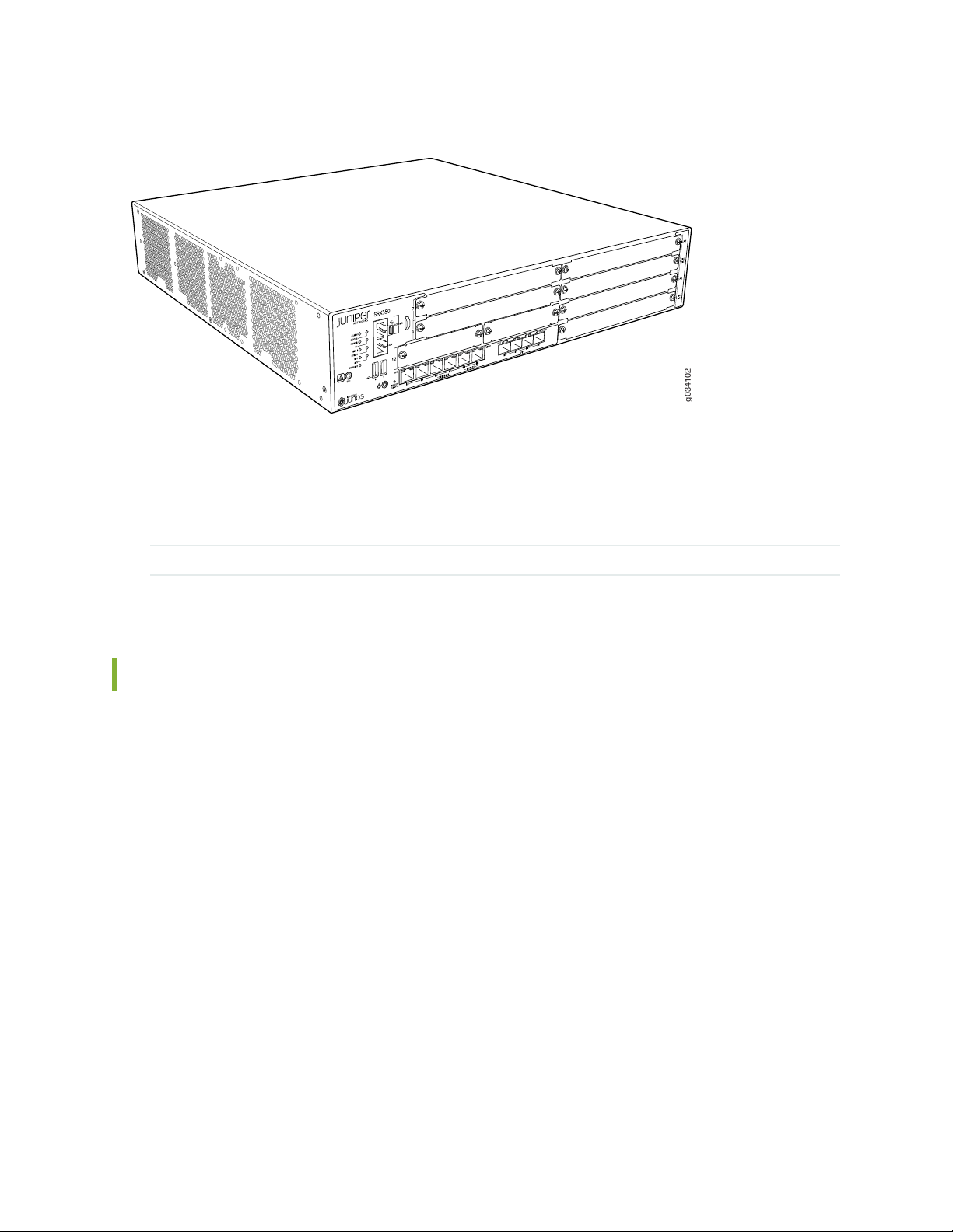
Figure 1: SRX550 Services Gateway
g034102
RELATED DOCUMENTATION
3
SRX550 Services Gateway Chassis | 14
Accessing the SRX550 Services Gateway | 11
SRX550 Services Gateway Software Features and Licenses | 4
SRX550 Services Gateway Hardware Features
The SRX550 Services Gateway provides the following features:
Symmetric Multiprocessing-based data forwarding.
•
Hardware-based control and data plane separation.
•
Six on-board 10/100/1000Base-T Gigabit Ethernet ports.
•
Four on-board SFP Gigabit Ethernet ports.
•
Support for dual AC or dual DC power supplies with a redundant configuration in the chassis. 645 W
•
AC and DC power supplies with or without Power over Ethernet (PoE) support. The AC and DC power
supplies are hot-swappable.
Junos OS support for advanced security and routing services on the Services and Routing Engine (SRE).
•
The services gateway supports Gigabit-Backplane Physical Interface Modules (GPIMs) and also Mini
•
Physical Interface Modules (Mini-PIMs). For details about the supported GPIMs and Mini-PIMs, see the
SRX Series Services Gateways for the Branch Physical Interface Modules Hardware Guide.
Page 20

RELATED DOCUMENTATION
SRX550 Services Gateway Description | 2
Accessing the SRX550 Services Gateway | 11
SRX550 Services Gateway Software Features and Licenses | 4
SRX550 Services Gateway Chassis | 14
Physical Interface Modules
SRX550 Services Gateway Software Features and Licenses
The services gateway provides the software features listed in Table 3 on page 5.
NOTE: Some software features require the purchase of a separate license.
4
For information about features that require a license on this services gateway, see the Installation and
Upgrade Guide for Security Devices.
Page 21

Table 3: Software Features and Licenses
Feature
Category
Feature
OSPFRouting
BGP
Routing Information Protocol version 1 (RIPv1) and version 2 (RIPv2)
Static routes
Intermediate System-to-Intermediate System (IS-IS)
Connectionless Network Service (CLNS):
End System-to-Intermediate System (ES-IS) protocol
•
IS-IS extensions
•
BGP extensions
•
Static routes
•
5
Internet
protocols
IP address
management
NOTE: CLNS is available only in packet-based mode.
MPLS:
Layer 2 and Layer 3 virtual private networks (VPNs)
•
VPN routing and forwarding (VRF) table labels
•
Traffic engineering protocols such as LDP and RSVP
•
Virtual private LAN service (VPLS)
•
Multicast VLAN
•
NOTE: MPLS is available in both packet-based mode and selective packet mode.
IPv4
•
IPv6 routing and forwarding
•
Static addresses
•
Dynamic Host Configuration Protocol (DHCP) 8
•
Page 22

Table 3: Software Features and Licenses (continued)
Feature
Category
Feature
6
Encapsulation
Ethernet
switching
Ethernet:
Media access control (MAC) encapsulation
•
802.1p tagging
•
Point-to-Point Protocol over Ethernet (PPPoE)
•
Circuit cross-connect (CCC)
•
Translational cross-connect (TCC)
•
Synchronous Point-to-Point Protocol (PPP)
Frame Relay
High-Level Data Link Control (HDLC)
802.1Q filtering and forwarding
Multilink Frame Relay (MLFR)
Multilink PPP
Line-rate Ethernet switching provided by XPIMs, including support for VLANs, spanning tree,
link aggregation, and authentication
Page 23

Table 3: Software Features and Licenses (continued)
Feature
Category
Feature
IPsec VPN for site-to-site or remote access encrypted tunnelingSecurity
Antivirus filtering, including full antivirus file-based scanning or Express-AV packet-based
scanning
Antispam and anti-phishing filtering
Web filtering
Content filtering based on file types and types of files within HTTP and HTTPS
Unified threat management (UTM)
7
Network attack detection
Denial of service (DoS) and distributed denial of service (DDoS) protection
Generic routing encapsulation (GRE), IP-over-IP, and IP Security (IPsec) tunnels
Advanced Encryption Standard (AES) 128-bit, 192-bit, and 256-bit
56-bit Data Encryption Standard (DES) and 168-bit 3DES encryption
MD5 and Secure Hash Algorithm 1 (SHA-1) authentication
Stateful firewall and stateless packet filters
Network Address Translation (NAT)
Page 24

Table 3: Software Features and Licenses (continued)
Feature
Category
management
Feature
Junos XML protocol XML application programming interface (API)System
The J-Web browser interface—For services gateway configuration and management
Junos OS command-line interface (CLI)—For services gateway configuration and management
through the console through Telnet, or SSH
Simple Network Management Protocol version 1 (SNMPv1), SNMPv2, and SNMPv3
Network and Security Manager (NSM)
J-Flow flow monitoring and accounting
8
and monitoring
Packet captureTraffic analysis
Real-time performance monitoring (RPM)
System log
The J-Web interface event viewerActivity logging
Traceroute
Supports the following external administrator databases:
RADIUS/AAA
•
TACACS+
•
Page 25

Table 3: Software Features and Licenses (continued)
Feature
Category
Feature
AutoinstallationAdministration
Configuration rollback
Button-operated configuration rescue (the CONFIG button)
Confirmation of configuration changes
Software upgrades
Supports the following features for automating network operations and troubleshooting:
Commit scripts
•
Operation scripts
•
Event policies
•
9
GPIMs and XPIMs are not hot-swappable on the SRX550 Services Gateway.Hot-swappable
LAN bypass ports are not supported on the SRX Series Services Gateways.Bypass ports
RELATED DOCUMENTATION
SRX550 Services Gateway Description | 2
SRX550 Services Gateway Hardware Features | 3
SRX550 Services Gateway Power over Ethernet
Power over Ethernet (PoE) supports the implementation of the IEEE802.3 af and IEEE802.3 at standards,
which allow both data and electric power to pass over a copper Ethernet LAN cable.
The SRX550 Services Gateway provides PoE ports, which supply electric power over the same ports that
are used to connect network devices. PoE ports allow you to plug in devices that require both network
connectivity and electric power, such as Voice over IP (VoIP) and IP phones and wireless access points.
The PoE ports for the SRX550 Services Gateway reside on the individual XPIMs. The SRX550 Services
Gateway supports the following XPIMs with PoE:
Page 26

16-Port Gigabit Ethernet XPIM
•
24-Port Gigabit Ethernet XPIM
•
The Services and Routing Engine (SRE) manages the overall system PoE power. You can configure the
services gateway to act as power sourcing equipment to supply the power to the GPIMs connected on
the designated PoE ports.
Table 4 on page 10 lists the SRX550 Services Gateway PoE specifications.
Table 4: SRX550 Services Gateway PoE Specifications
ValuesPower Management Schemes
10
Supported standards
Supported slots
Total PoE power sourcing capacity
IEEE802.3 af
•
IEEE802.3 at
•
Legacy
•
PoE is supported on the following front panel slots:
3
•
4
•
6
•
8
•
For more information, see “SRX550 Services Gateway Front Panel”
on page 15.
The 645 W AC and 645 W DC power supplies support the
following capacities:
255 W PoE on a single power supply, or with redundancy using
•
the two power supply option
510 W PoE using the two power supply option operating as
•
nonredundant
31.2 WPer-port power limit
Power management modes
Static: Power allocated for each interface can be configured
•
Class: Power allocation for interfaces is decided based on the
•
class of powered device connected
For details about the GPIMs and XPIMs, see the SRX Series Services Gateways for the Branch Physical
Interface Modules Hardware Guide.
RELATED DOCUMENTATION
Page 27

SRX550 Services Gateway Gigabit-Backplane Physical Interface Modules | 24
SRX550 Services Gateway Power Supply | 28
SRX550 Services Gateway Back Panel | 22
Physical Interface Modules
Accessing the SRX550 Services Gateway
You can use two user interfaces to monitor, configure, troubleshoot, and manage the Juniper Networks
Services Gateway:
The J-Web interface: A Web-based graphical interface that allows you to operate a services gateway
•
without commands. The J-Web interface provides access to all Junos OS functionality and features.
Junos OS command-line interface (CLI): Juniper Networks command shell that runs on top of a UNIX-based
•
operating system kernel. The CLI is a straightforward command interface. On a single line, you type
commands that are executed when you press the Enter key. The CLI provides command help and
command completion.
11
RELATED DOCUMENTATION
SRX550 Services Gateway Description | 2
SRX550 Services Gateway Hardware Features | 3
SRX550 Services Gateway Software Features and Licenses | 4
Page 28

CHAPTER 2
Hardware Component Overview
IN THIS CHAPTER
SRX550 Services Gateway Boot Devices and Dual-Root Partitioning Scheme | 12
SRX550 Services Gateway Boot Devices and Dual-Root Partitioning Scheme
By default, the SRX550 Services Gateway boots from the following storage media (in order of priority):
12
1. Internal CompactFlash card (default; always present)
2. USB storage key (alternate)
NOTE: When you explicitly boot the services gateway using the CLI and the services gateway
has two USBs installed (one in slot 0 and the second in slot 1), if the USB in slot 0 fails, the
booting sequence will not boot from the second USB installed in slot 1. Instead, the device will
boot using the next storage media in its storage media booting priority list, the internal
CompactFlash card.
The dual-root partitions allow the services gateways to remain functional if there is file system corruption
and facilitate easy recovery of the corrupted file system.
The dual-root partitioning scheme keeps the primary and backup Junos OS images in two independently
bootable root partitions. If the primary root partition is corrupted, the system will be able to boot from
the backup Junos OS image located in the other root partition and remain fully functional.
When the services gateway powers up, it tries to boot Junos OS from the default storage media. If the
device fails to boot from the default storage media, it tries to boot from the alternate storage media. With
the dual-root partitioning scheme, the device first tries to boot Junos OS from the primary root partition
and then from the backup root partition on the default storage media. If both primary and backup root
partitions of a media fail to boot, then the device tries to boot Junos OS from the next available type of
storage media. The services gateway remains fully functional even if it boots the Junos OS from the backup
root partition of storage media.
Page 29

RELATED DOCUMENTATION
Installation Overview for the SRX550 Services Gateway | 60
Required Tools and Parts for Installing the SRX550 Services Gateway | 61
SRX550 Services Gateway Basic Connectivity Overview | 95
13
Page 30
CHAPTER 3
Chassis Description
IN THIS CHAPTER
SRX550 Services Gateway Chassis | 14
SRX550 Services Gateway Front Panel | 15
SRX550 Services Gateway Front Panel LEDs | 19
SRX550 Services Gateway Back Panel | 22
14
SRX550 Services Gateway Chassis
The SRX550 Services Gateway chassis is a rigid sheet metal structure that houses all the other hardware
components.
Table 5 on page 14 provides information about the physical specifications for the services gateway.
Table 5: Physical Specifications for the SRX550 Services Gateway
ValuePhysical Specification
2 rack units (U)Chassis height
17.5 in. (44.4 cm)Chassis width
18.2 in. (46.2 cm)Chassis depth
21.96 lb (9.96 kg)Chassis weight (includes one power supply without any GPIMs or
Mini-PIMs)
CAUTION: Before removing or installing components of a functioning services gateway,
attach an electrostatic discharge (ESD) strap to an ESD point and place the other end
of the strap around your bare wrist. Failure to use an ESD strap could result in damage
to the device.
Page 31

The services gateway must be connected to earth ground during normal operation. The protective earthing
g034100
1
8
10
9
11 12 13
2 3 4 5 6 7
terminal on the side of the chassis is provided to connect the services gateway to ground. Additional
grounding is provided to an AC-powered services gateway when you plug its power supply into a grounded
AC power receptacle.
RELATED DOCUMENTATION
SRX550 Services Gateway Description | 2
SRX550 Services Gateway Front Panel | 15
SRX550 Services Gateway Back Panel | 22
Grounding the SRX550 Services Gateway | 77
General Electrical Safety Guidelines and Warnings
15
SRX550 Services Gateway Front Panel
Figure 2 on page 15 shows the front panel of the SRX550 Services Gateway.
Figure 2: SRX550 Services Gateway Front Panel
Table 6 on page 15 provides information about the front panel components of the services gateway with
reference to Figure 2 on page 15.
Table 6: SRX550 Services Gateway Front Panel Components
DescriptionLocationComponentNumber
Front panel LEDs1
Left side of the
front chassis
panel
Indicate the current status of the services gateway. See
“SRX550 Services Gateway Front Panel LEDs” on
page 19 for detailed information about the front panel
LEDs.
Page 32

Table 6: SRX550 Services Gateway Front Panel Components (continued)
DescriptionLocationComponentNumber
16
Serial Console Port2
USB Console Port3
AUX Port4
5
2 Mini-PIM slots
numbered 1 and 2
Left side of the
front chassis
panel
Left side of the
front chassis
panel
Left side of the
front chassis
panel
front chassis
panel
Connects a laptop to the services gateway for CLI
management. The port uses an RJ-45 serial connection,
is configured as data terminal equipment (DTE), and
supports the RS-232 (EIA-232) standard.
Connects a laptop to the services gateway for CLI
management through a USB interface. The port accepts
a Mini-B type USB cable plug. A USB cable with Mini-B
and Type A USB plugs is supplied with the services
gateway. To use the USB console port, you must
download a USB driver to the management station from
the Juniper Networks website.
NOTE: The Auxiliary port is not supported on the
SRX550 Services Gateway.
Both slots support Mini-PIMs.Left side of the
6
8
6 GPIM slots
numbered 3 through
8. For specific
GPIM/XPIM slots, see
Figure 3 on page 19
Electrostatic
discharge (ESD) outlet
Front chassis
panel
Sides of chassisMounting brackets7
Left side of the
front chassis
panel
All slots support GPIMs.
•
Slot 3 supports 10-gigabit XPIMs.
•
Slot 6 supports 20-gigabit XPIMs.
•
Slots 3, 4, 6, and 8 support PoE. For more information
•
about PoE, see “SRX550 Services Gateway Power
over Ethernet” on page 9.
NOTE: SRX550 Services Gateway does not support
hot-swappable functionality for GPIMs and XPIMs
Rack-mounting brackets attached when the services
gateway is mounted on a rack.
The mounting brackets are used to attach the services
gateway to a rack or cabinet.
While working on the services gateway, use the ESD
outlet to plug in an ESD grounding strap to prevent your
body from sending static charges to the services
gateway, which will damage the device.
Page 33

Table 6: SRX550 Services Gateway Front Panel Components (continued)
DescriptionLocationComponentNumber
17
9
USB 0 and USB 1
ports
Power button10
Left side of the
front chassis
panel
Left side of the
front chassis
panel
The services gateway has two USB ports, labeled USB
0 and USB 1, that accept a USB storage device. These
USB ports accept USB flash drives with Type A plugs.
When the USB drive is installed and configured, it
automatically acts as the secondary boot device if the
primary CompactFlash card fails on startup.
NOTE: You must install Junos OS on the USB storage
device to use it as the secondary boot device. The
services gateway supports the following USB devices:
Lexar 2 GB
•
Juniper Networks 2 GB
•
Depending on the capacity of the USB drive, you can
also configure it to receive core files generated during
a failure.
Use the Power button to shut down the services
gateway.
On a services gateway that has been previously shut
down using the Power button, when the power button
is pressed again the services gateway starts up.
11
RESET CONFIG
Button
Left side of the
front chassis
panel
WARNING: The Power button does not shut off power
to the power supplies or the midplane. You must remove
the power cables or power cords to completely shut
down the services gateway. The DC OK LED light on
the power supply unit (PSU) changes from green to
amber indicating that the software has stopped running.
After the software has stopped running, you can safely
remove any GPIMs or Mini-PIMs from the services
gateway.
Returns the services gateway to the rescue configuration
or the factory default configuration. For more
information, see “Resetting the SRX550 Services
Gateway” on page 137.
Page 34

Table 6: SRX550 Services Gateway Front Panel Components (continued)
DescriptionLocationComponentNumber
18
12
13
6 fixed Gigabit
Ethernet ports:
Port labeled 0/0
•
Port labeled 0/1
•
Port labeled 0/2
•
Port labeled 0/3
•
Port labeled 0/4
•
Port labeled 0/5
•
Provides link speeds
of 10/100/1000
Mbps.
4 SFP Ethernet ports:
Port labeled 0/6
•
Port labeled 0/7
•
Port labeled 0/8
•
Port labeled 0/9
•
Provides link speeds
of 10/100/1000
Mbps.
Left side of the
front chassis
panel, lower edge
Middle of the
front chassis
panel, lower edge
The Gigabit Ethernet ports have the following
characteristics:
Use an RJ-45 connector.
•
Operate in full-duplex and half-duplex modes.
•
Support flow control.
•
Support autonegotiation.
•
The Gigabit Ethernet ports can:
Function as front-end network ports.
•
Provide LAN and WAN connectivity to hubs, switches,
•
local servers, and workstations.
Forward incoming data packets to the services
•
gateway.
Receive outgoing data packets from the services
•
gateway.
NOTE: LAN bypass is not supported on the services
gateway.
The SFP Ethernet ports have the following
characteristics:
Operate in full-duplex and half-duplex modes.
•
Support flow control.
•
Support autonegotiation.
•
The SFP Ethernet ports can:
Function as front-end network ports.
•
Provide LAN and WAN connectivity to hubs, switches,
•
local servers, and workstations.
Forward incoming data packets to the services
•
gateway.
Receive outgoing data packets from the services
•
gateway.
Page 35
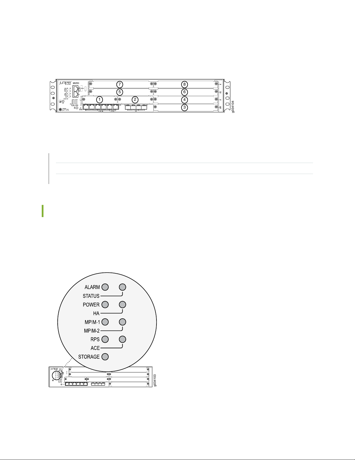
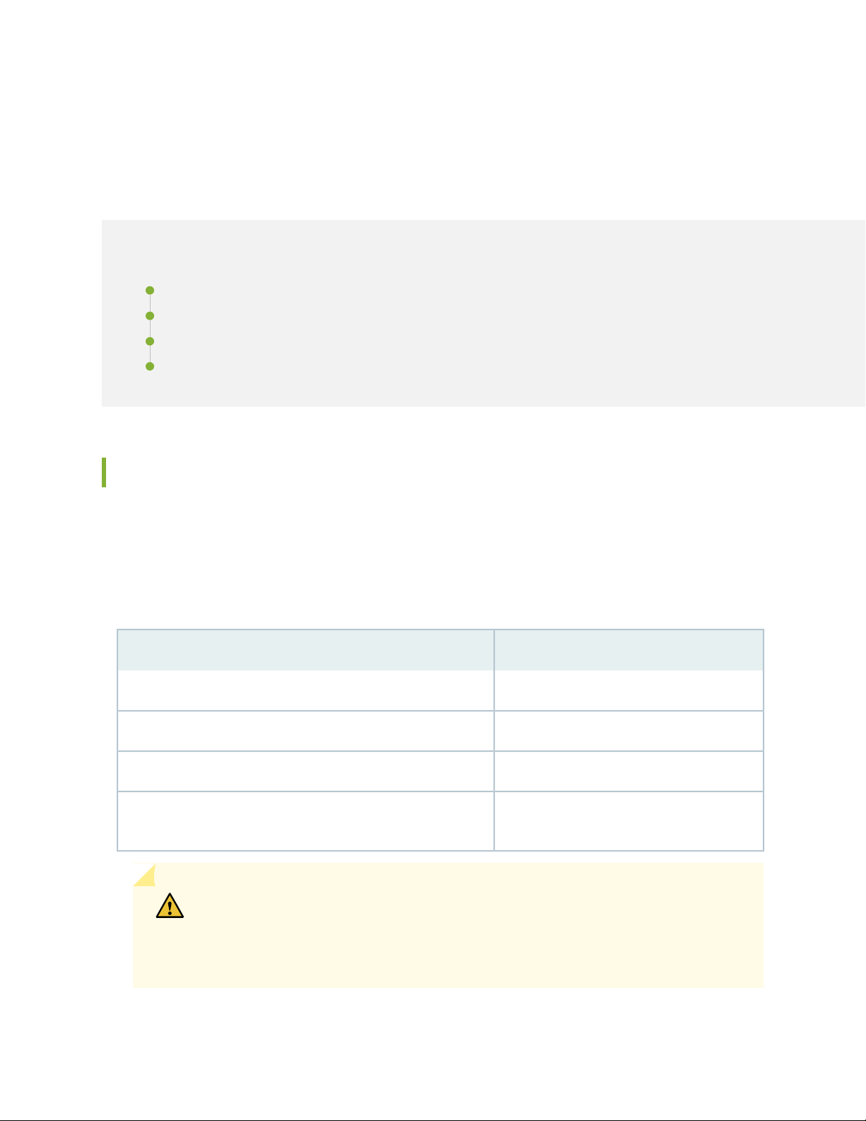
Figure 3 on page 19 shows how the slots on the front panel of the SRX550 Services Gateway are numbered.
g034104
1
3
2
4
6
8
5
7
g034103
Figure 3: SRX550 Services Gateway Slot Numbers
RELATED DOCUMENTATION
SRX550 Services Gateway Front Panel LEDs | 19
SRX550 Services Gateway Chassis | 14
SRX550 Services Gateway Back Panel | 22
19
SRX550 Services Gateway Front Panel LEDs
Figure 4 on page 19 shows the locations of the SRX550 Services Gateway front panel LEDs.
Table 7 on page 20 describes the LEDs.
Figure 4: SRX550 Services Gateway Front Panel LED Locations
Page 36

Table 7: SRX550 Services Gateway Front Panel LEDs
20
LED
Label
LED
ColorLED State
AmberOn SteadilyALARM
Red
UnlitOff
Description
Indicates a major alarm, such as low Services Processing Unit (SPU)
memory (less than 10% remaining), session full, maximum number of VPN
tunnels reached, high availability (HA) status changed, or redundant group
member not found.
Indicates a critical alarm, such as a failure of a hardware component or
software module.
indicates that the device is starting up.
NOTE: When the system is up and running, if the ALARM LED is off, it
indicates that no alarms are active on the device.
The services gateway is functioning normally.GreenOn SteadilySTATUS
The services gateway is starting up, running diagnostics, or shutting down.Amber
The services gateway has failed.Red
GreenSteadily onPOWER
Amber
The services gateway is powered off.UnlitOff
The services gateway is functioning normally and that the services gateway
and all power supply units (PSUs) are receiving power.
At least one PSU has failed.Red
The Power button has been pressed and that the services gateway is
shutting down.
The services gateway is not receiving power.UnlitOff
Page 37

Table 7: SRX550 Services Gateway Front Panel LEDs (continued)
21
LED
Label
MPIM-2
LED
ColorLED State
Red
Amber
Red
UnlitOff
Description
All configured high availability links are available.GreenSteadily onHA
High availability links are not working as expected and a cluster member
might be missing or unreachable.
Some configured high availability links are down, but enough links are
still active for full high availability functionality. In this situation,
performance might be reduced, current bandwidth could cause packet
drops, or a single point of failure might now exist.
High availability is not enabled.UnlitOff
The Mini-PIM in the corresponding slot is functioning normally.GreenOn SteadilyMPIM-1,
The Mini-PIM hardware in the corresponding slot has failed or its
anti-counterfeit check failed.
There is no Mini-PIM in the corresponding slot, or that the Mini-PIM is
not detected by the device.
The redundant power supply is operating normallyGreenOn SteadilyRPS
Red
NOTE: The ACE LED is not functional.ACE
GreenBlinkingSTORAGE
GreenOn Steadily
One of the following conditions has occurred:
The primary power supply has failed, and the device is being powered
•
by the redundant power supply.
The redundant power supply has been installed, but is not connected
•
to a power source.
The redundant power supply is not installed.UnlitOff
The services gateway is transferring data to or from the optional storage
device.
The optional storage device is installed but no data is being transferred
to or from it.
The optional storage device is not installed.UnlitOff
Page 38
RELATED DOCUMENTATION
g034101
7 5 4
3
6
21
SRX550 Services Gateway Front Panel | 15
SRX550 Services Gateway Chassis | 14
SRX550 Services Gateway Back Panel | 22
SRX550 Services Gateway Back Panel
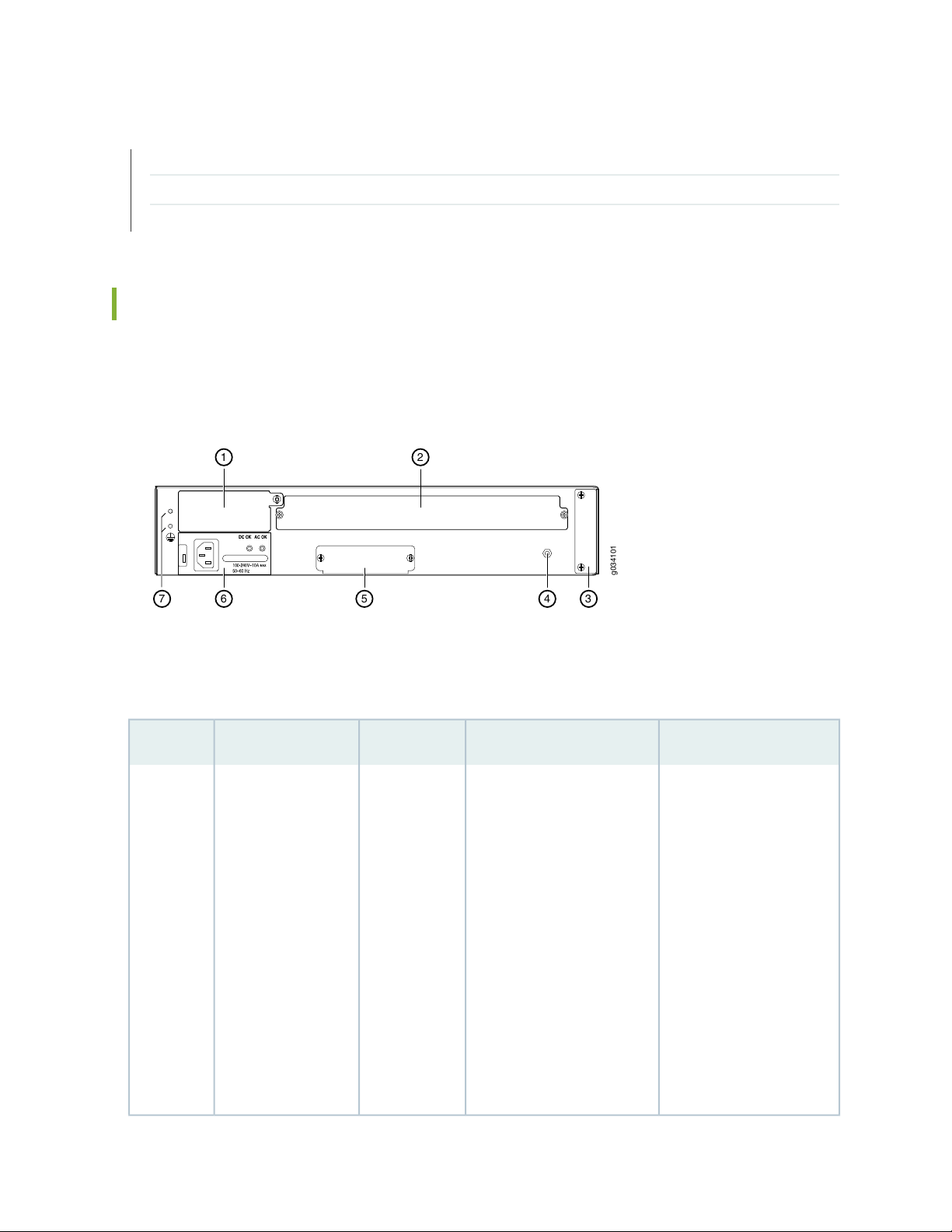
Figure 5 on page 22 shows the back panel of the SRX550 Services Gateway.
Figure 5: SRX550 Services Gateway Back Panel
22
Table 8 on page 22 describes the components on the back panel of the SRX550 Services Gateway with
reference to Figure 5 on page 22.
Table 8: SRX550 Services Gateway Back Panel Components
UsageDescriptionLocationComponentNumber
1
Two power supply
slots. Each power
supply contains a
power cord outlet.
One 645 W AC
power supply is
provided with the
services gateway.
Left side of
back panel
The power supply provides
power to the services
gateway and its components.
When the services gateway
is equipped with the two
power supply option, they
work together to provide
redundancy and load-sharing.
The following power supplies
are available:
645 W AC power supply
•
with PoE power
645 W DC power supply
•
with PoE power
Power supplies are
hot-swappable and support
single- or dual-redundant
power supply versions.
If you need to power off
the services gateway after
it finishes booting, first use
the CLI to halt the device.
Page 39

Table 8: SRX550 Services Gateway Back Panel Components (continued)
23
UsageDescriptionLocationComponentNumber
ACE Slot2
the back panel
Grounding point3
Storage slot4
5
Electrostatic
discharge (ESD)
outlet
Air filter cover6
Left side of the
back panel
Center of the
back panel,
lower edge
Right side of
the back panel
Right of the
back panel
NOTE: This slot is not used.Top center of
Contains two M4 screws that
you use to connect the
grounding cable to the
services gateway chassis.
Slot where you can install an
extra data storage device.
Connector for an ESD wrist
band.
Provides access to the
optional air filter.
NOTE: The air filter is not
currently orderable.
Connects the services
gateway chassis to earth
ground.
Supplements the data
storage capacity of the
services gateway.
While working on the
services gateway, use the
ESD outlet to plug in an
ESD grounding strap to
prevent any damage to the
services gateway.
The optional air filter helps
keep the services gateway
and its components free
from dust particles. The air
filter is hot-swappable.
RELATED DOCUMENTATION
SRX550 Services Gateway Chassis | 14
SRX550 Services Gateway Front Panel | 15
SRX550 Services Gateway Power Supply | 28
NOTE: The air filter is
required for NEBS
compliance.
Page 40

CHAPTER 4
Interface Module Description
IN THIS CHAPTER
SRX550 Services Gateway Gigabit-Backplane Physical Interface Modules | 24
SRX550 Services Gateway Mini-Physical Interface Modules | 26
SRX550 Services Gateway Gigabit-Backplane Physical Interface Modules
24
A Gigabit-Backplane Physical Interface Module (GPIM) is a network interface card (NIC) that installs in the
front slots of the services gateway to provide physical connections to a LAN or a WAN. The GPIM receives
incoming packets from a network and transmits outgoing packets to a network. These modules complement
the onboard Ethernet interfaces to extend the types and port counts of network connections for the LAN
or WAN.
Interface Module Terminology:
GPIM—The Gigabit-Backplane Interface Module (GPIM) includes standard GPIMs that can be installed
•
in a single-high, single-wide GPIM slot that has gigabit connectivity to the system backplane.
XPIM—The XPIM can be installed only in the 10-gigabit GPIM slot 3 or in the 20-gigabit GPIM slot 6. It
•
could be:
A single-high, single-wide LAN switch XPIM that uses one slot
•
A double-high, single-wide LAN switch XPIM that uses two standard slots vertically
•
A double-high, double-wide LAN switch XPIM that uses two standard slots vertically and two standard
•
slots horizontally
NOTE: When installing the 24-Port Gigabit Ethernet XPIM, which uses four slots, you must
install it in the 20-gigabit GPIM slot 6, which refers to the top four slots 5 through 8.
Figure 6 on page 25 shows how the slots on the front panel of the SRX550 Services Gateway are numbered.
Page 41
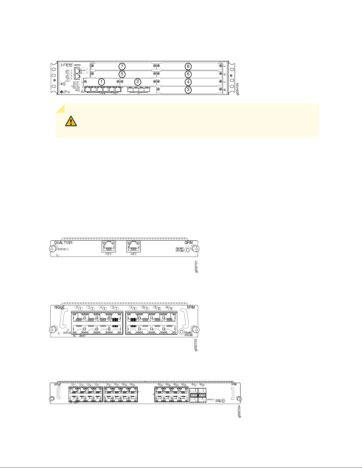
Figure 6: SRX550 Services Gateway Slot Numbers
g034104
1
3
2
4
6
8
5
7
g032721
g032723
g032724
CAUTION: SRX550 Services Gateway does not support hot-swappable functionality
for GPIMs.
For more information about supported GPIMs and the minimum supported Junos OS release, see SRX
Series Services Gateway Interface Modules and Compatibility
For details about the supported GPIMs and XPIMs, see the SRX Series Services Gateways for the Branch
Physical Interface Modules Hardware Guide.
25
Figure 7 on page 25, Figure 8 on page 25, and Figure 9 on page 25 show the three form factors for the
services gateway GPIMs.
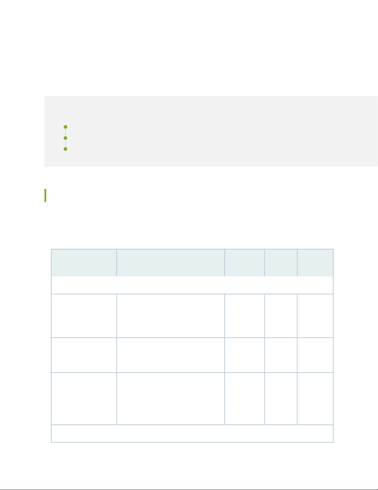
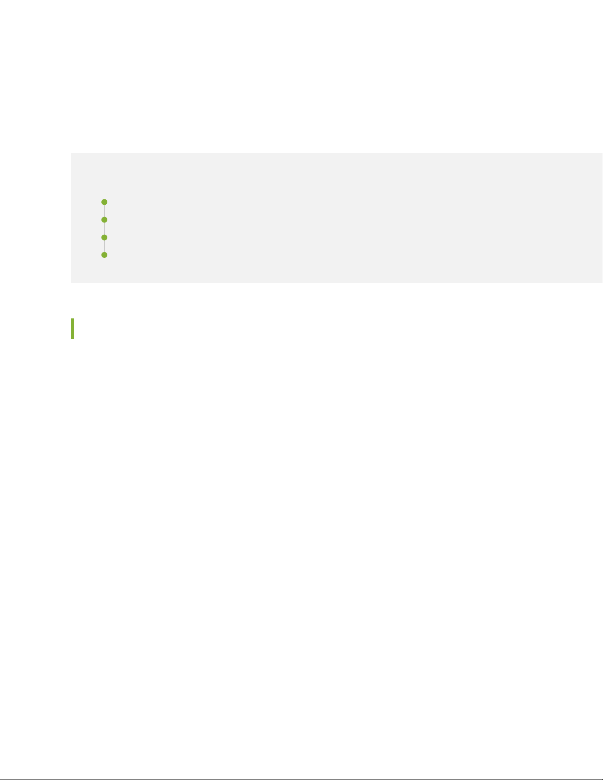
Figure 7: Example of a Standard GPIM (Installs in One Standard Slot)
Figure 8: Example of a Double-High, Single-Wide XPIM
Figure 9: Example of a Double-High, Double-Wide XPIM
Page 42

Because the services gateway GPIMs communicate with the backplane at various performance levels, you
must install them in the correct slots.
NOTE: Remove the GPIM adapter before you install double-high, double-wide XPIM.
RELATED DOCUMENTATION
SRX550 Services Gateway Front Panel | 15
SRX550 Services Gateway Power over Ethernet | 9
Installing a Double-High, Double-Wide Gigabit-Backplane Physical Interface Module on the SRX Series
Services Gateway
Physical Interface Modules
26
SRX550 Services Gateway Mini-Physical Interface Modules
The SRX550 Services Gateway has two slots for installing Mini-Physical Interface Modules (Mini-PIMs).
A Mini-PIM is a network interface card that is installed in the services gateway to provide physical
connections to a LAN or WAN. The Mini-PIMs supported on the services gateway are field-replaceable
units (FRUs); which you can remove or replace at your site. You can install Mini-PIMs into the two Mini-PIM
slots on the front panel of the services gateway chassis.
For more information about supported Mini-PIMs and the minimum supported Junos OS release, see SRX
Series Services Gateway Interface Modules and Compatibility.
For more information about supported Mini-PIMs, including how to install and configure Mini-PIMs, see
the SRX Series Services Gateways for the Branch Physical Interface Modules Hardware Guide.
RELATED DOCUMENTATION
SRX550 Services Gateway Front Panel | 15
SRX550 Services Gateway Power over Ethernet | 9
Physical Interface Modules
Page 43

CHAPTER 5
Cooling System Description
IN THIS CHAPTER
SRX550 Services Gateway Cooling System | 27
SRX550 Services Gateway Cooling System
The SRX550 Services Gateway cooling system consists of four fixed fans. The fans provide cooling to the
components installed in the services gateway. To function properly, the entire cooling system requires an
unobstructed airflow and proper clearance around the site.
27
The fan controller constantly monitors the temperature of the services gateway and all modules (Mini-PIMs
and GPIMs) installed in the device. Under normal operating conditions, the fans function at lower than full
speed.
If any one of the four fans fails, the services gateway generates a warning but keeps the system running.
If the temperature keeps rising, the services gateway lowers the power consumption by reducing the
performance or shutting down some of the chassis components. However, if the ambient maximum
temperature specification exceeds the warning limit and the system cannot be adequately cooled, then
the services gateway shuts down the system and hardware components completely.
RELATED DOCUMENTATION
SRX550 Services Gateway Chassis | 14
SRX550 Services Gateway Description | 2
SRX550 Services Gateway Front Panel | 15
SRX550 Services Gateway Back Panel | 22
Page 44

CHAPTER 6
Power System Description
IN THIS CHAPTER
SRX550 Services Gateway Power Supply | 28
SRX550 Services Gateway Power Supply
The SRX550 Services Gateway uses either one AC or one DC power supply unit (PSU). The services
gateway is equipped with one AC power supply (see Figure 10 on page 29) for non-power redundancy. A
second PSU is optional (sold separately) for power redundancy. A second PSU can be used to meet power
requirements exceeding the wattage provided by a single PSU (a nonredundant configuration). The two
power supplies, either both AC or both DC, will load-share and provide power redundancy to the services
gateway, increasing its availability and reliability. If one power supply fails or is removed, the other power
supply redistributes the electrical load without interruption. The services gateway reassesses the power
required to support its configuration and issues errors if the available power is insufficient.
Figure 11 on page 29 shows the diagram of the DC power supply.
28
CAUTION: Do not mix AC and DC power supplies within the same services gateway
because this can damage the device.
All power supplies are hot-swappable and support single or dual redundant power supply versions. Each
power supply is cooled by the system’s fans.
Page 45

Figure 10: AC Power Supply
g032709
Figure 11: DC Power Supply
29
The power supplies provide different output wattage to the services gateway components according to
the voltage requirements of the components.
The power supply components are listed in Table 9 on page 30.
Page 46

Table 9: Component Power Output/Consumption
Output/ConsumptionPower Supply
30
645 W AC power supply
645 W DC power supply
This power supply can provide:
390 W at 12 V
•
255 W PoE on a single power supply, or with redundancy using the
•
two power supplies
510 W PoE using the two power supply option operating as
•
nonredundant
NOTE: Using the two power supply option operating as nonredundant
for up to 510 W PoE power, the administrator has the ability to prioritize
the PoE ports that will receive power if an outage should occur to either
the power source or to one of the power supplies.
This power supply can provide:
390 W at 12 V
•
255 W PoE on a single power supply, or with redundancy using the
•
two power supply option
510 W PoE using the two power supply option operating as
•
nonredundant
NOTE: Using the two power supply options operating as nonredundant
for up to 510 W PoE, the administrator has the ability to prioritize the
PoE ports that will receive power if an outage should occur to either the
power source or to one of the power supplies.
The DC power supply has connections for two DC power feeds labeled A and B, each with a positive (+)
and a negative (-) terminal. You can connect the DC power supply to both the feeds. If either feed fails,
the power supply draws all its power from the other feed. This configuration provides the commonly
deployed A/B feed redundancy for the system. Table 10 on page 30 describes the connection terminals
on the DC power supply.
Table 10: DC Power Supply Terminals
DescriptionLabelFeed
RTN connection for Feed AA+Feed A
-48VDC connection for Feed AA-
Page 47

Table 10: DC Power Supply Terminals (continued)
DescriptionLabelFeed
RTN connection for Feed BB+Feed B
-48VDC connection for Feed BB-
RELATED DOCUMENTATION
SRX550 Services Gateway Chassis | 14
SRX550 Services Gateway Front Panel | 15
SRX550 Services Gateway Back Panel | 22
SRX550 Services Gateway Cooling System | 27
Troubleshooting the Power System on the SRX550 Services Gateway | 130
31
Page 48

2
PART
Site Planning and Specifications
Planning and Preparing the Site | 33
Rack Requirements | 38
Cabinet Requirements | 47
Power Requirements and Specifications | 49
Cable Specifications and Pinouts | 56
Page 49
CHAPTER 7
Planning and Preparing the Site
IN THIS CHAPTER
Site Preparation Checklist for the SRX550 Services Gateway | 33
General Site Installation Guidelines for the SRX550 Services Gateway | 35
SRX550 Services Gateway Environmental Specifications | 36
Site Preparation Checklist for the SRX550 Services Gateway
33
The checklist in Table 11 on page 33 summarizes the tasks you need to perform when preparing a site for
installing the SRX550 Services Gateway.
Table 11: Site Preparation Checklist for SRX550 Services Gateway Installation
Performed
NotesDate
Power
Measure distance
between external power
sources and device
installation site.
Locate sites for
connection of system
grounding.
Calculate the power
consumption and
requirements.
ByAdditional InformationItem or Task
“SRX550 Services Gateway Electrical
Wiring Guidelines” on page 49
“Grounding the SRX550 Services Gateway”
on page 77
“SRX550 Services Gateway AC Power
Supply Electrical Specifications” on
page 52 and “SRX550 Services Gateway
DC Power Supply Electrical Specifications”
on page 54
Environment
Page 50

Table 11: Site Preparation Checklist for SRX550 Services Gateway Installation (continued)
Performed
ByAdditional InformationItem or Task
34
NotesDate
Verify that
environmental factors
such as temperature and
humidity do not exceed
device tolerances.
Rack Installation
Verify that your rack
meets the minimum
requirements.
Plan rack location,
including required space
clearances.
Secure the rack to the
floor and building
structure.
Cabinet Installation
“SRX550 Services Gateway Environmental
Specifications” on page 36
“SRX550 Services Gateway Rack Size and
Strength Requirements” on page 43
“SRX550 Services Gateway Spacing of
Mounting Bracket and Flange Holes” on
page 44
“Connecting the SRX550 Services Gateway
to the Building Structure” on page 68
Verify that your cabinet
meets the minimum
requirements.
Plan the cabinet
location, including
required space
clearances.
Cables
Acquire cables and
connectors.
“SRX550 Services Gateway Cabinet Size
and Clearance Requirements” on page 47
“SRX550 Services Gateway Cabinet
Airflow Requirements” on page 48
“Interface Cabling and Wiring
Specifications for the SRX550 Services
Gateway” on page 56
Page 51

Table 11: Site Preparation Checklist for SRX550 Services Gateway Installation (continued)
Performed
ByAdditional InformationItem or Task
Review the maximum
distance allowed for
each cable. Choose the
length of cable based on
the distance between
the hardware
components being
connected.
Plan the cable routing
and management.
35
NotesDate
RELATED DOCUMENTATION
SRX550 Services Gateway Chassis | 14
Installation Overview for the SRX550 Services Gateway | 60
General Site Installation Guidelines for the SRX550 Services Gateway | 35
General Site Installation Guidelines for the SRX550 Services Gateway
The following precautions help you plan an acceptable operating environment for your SRX550 Services
Gateway and avoid environmentally caused equipment failures:
For the cooling system to function properly, the airflow around the chassis must be unrestricted. Allow
•
sufficient clearance between the front and back of the chassis and adjacent equipment. Ensure that
there is adequate circulation in the installation location.
Follow the ESD procedures to prevent any damage equipment. Static discharge can cause components
•
to fail completely or intermittently over time. For more information, see Preventing Electrostatic Discharge
Damage to the SRX550 Services Gateway.
Ensure that the blank panels are installed into empty slots to prevent any interruption or reduction in
•
the flow of air across internal components.
Page 52

NOTE: Install the services gateway only in restricted areas, such as dedicated equipment rooms
and equipment closets, in accordance with Articles 110–16, 110–17, and 110–18 of the National
Electrical Code, ANSI/NFPA 70.
RELATED DOCUMENTATION
SRX550 Services Gateway Chassis | 14
SRX550 Services Gateway Cabinet Size and Clearance Requirements | 47
SRX550 Services Gateway Rack Size and Strength Requirements | 43
Clearance Requirements for Airflow and Hardware Maintenance of the SRX550 Services Gateway | 45
36
SRX550 Services Gateway Environmental Specifications
Table 12 on page 36 provides the required environmental conditions for normal SRX550 Services Gateway
operations. In addition, the site must be as dust-free as possible because dust can clog air intake vents,
reducing the efficiency of the cooling system.
Table 12: SRX550 Services Gateway Environmental Specifications
ValueDescription
No performance degradation to 13,000 ft (3962.4 m)Altitude
Relative humidity
Temperature
Normal operation ensured in relative humidity range of 5% to 90%,
noncondensing
Normal operation ensured in temperature range of 32°F (0°C) to 104°F
(40°C)
Nonoperating storage temperature in shipping container: –40°F (–40°C)
to 158°F (70°C)
Seismic
Designed to meet Telcordia Technologies Zone 4 earthquake
requirements
Page 53

Table 12: SRX550 Services Gateway Environmental Specifications (continued)
ValueDescription
37
Maximum thermal output
AC power: 4400 BTU/hour
DC power with one 645 W power supply unit: 2200 BTU/hour
DC power with two 645 W power supply units, nonredundant: 4400
BTU/hour
NOTE: These specifications are estimates and subject to change.
NOTE: Install the services gateway only in restricted areas, such as dedicated equipment rooms
and equipment closets, in accordance with Articles 110–16, 110–17, and 110–18 of the National
Electrical Code, ANSI/NFPA 70.
RELATED DOCUMENTATION
SRX550 Services Gateway General Safety Guidelines and Warnings
Routine Maintenance Procedures for the SRX550 Services Gateway | 123
Page 54
CHAPTER 8
Rack Requirements
IN THIS CHAPTER
Rack-Mounting Requirements and Warnings | 38
SRX550 Services Gateway Rack Size and Strength Requirements | 43
SRX550 Services Gateway Spacing of Mounting Bracket and Flange Holes | 44
Clearance Requirements for Airflow and Hardware Maintenance of the SRX550 Services Gateway | 45
38
Rack-Mounting Requirements and Warnings
Ensure that the equipment rack into which the services gateway is installed is evenly and securely supported
to avoid hazardous conditions that could result from uneven mechanical loading.
Page 55

39
Page 56

WARNING: To prevent bodily injury when mounting or servicing the services gateway
in a rack, take the following precautions to ensure that the system remains stable. The
following directives help maintain your safety:
The services gateway must be installed in a rack that is secured to the building
•
structure.
The services gateway should be mounted at the bottom of the rack if it is the only
•
unit in the rack.
When mounting the services gateway in a partially filled rack, load the rack from the
•
bottom to the top with the heaviest component at the bottom of the rack.
If the rack is provided with stabilizing devices, install the stabilizers before mounting
•
or servicing the services gateway in the rack.
Waarschuwing Om lichamelijk letsel te voorkomen wanneer u dit toestel in een rek
monteert of het daar een servicebeurt geeft, moet u speciale voorzorgsmaatregelen
nemen om ervoor te zorgen dat het toestel stabiel blijft. De onderstaande richtlijnen
worden verstrekt om uw veiligheid te verzekeren:
40
De Juniper Networks services gateway moet in een stellage worden geïnstalleerd
•
die aan een bouwsel is verankerd.
Dit toestel dient onderaan in het rek gemonteerd te worden als het toestel het enige
•
in het rek is.
Wanneer u dit toestel in een gedeeltelijk gevuld rek monteert, dient u het rek van
•
onderen naar boven te laden met het zwaarste onderdeel onderaan in het rek.
Als het rek voorzien is van stabiliseringshulpmiddelen, dient u de stabilisatoren te
•
monteren voordat u het toestel in het rek monteert of het daar een servicebeurt
geeft.
Varoitus Kun laite asetetaan telineeseen tai huolletaan sen ollessa telineessä, on
noudatettava erityisiä varotoimia järjestelmän vakavuuden säilyttämiseksi, jotta
vältytään loukkaantumiselta. Noudata seuraavia turvallisuusohjeita:
Juniper Networks services gateway on asennettava telineeseen, joka on kiinnitetty
•
rakennukseen.
Jos telineessä ei ole muita laitteita, aseta laite telineen alaosaan.
•
Jos laite asetetaan osaksi täytettyyn telineeseen, aloita kuormittaminen sen alaosasta
•
kaikkein raskaimmalla esineellä ja siirry sitten sen yläosaan.
Jos telinettä varten on vakaimet, asenna ne ennen laitteen asettamista telineeseen
•
tai sen huoltamista siinä.
Page 57

Attention Pour éviter toute blessure corporelle pendant les opérations de montage
ou de réparation de cette unité en casier, il convient de prendre des précautions
spéciales afin de maintenir la stabilité du système. Les directives ci-dessous sont
destinées à assurer la protection du personnel:
Le rack sur lequel est monté le Juniper Networks services gateway doit être fixé à
•
la structure du bâtiment.
Si cette unité constitue la seule unité montée en casier, elle doit être placée dans le
•
bas.
Si cette unité est montée dans un casier partiellement rempli, charger le casier de
•
bas en haut en plaçant l'élément le plus lourd dans le bas.
Si le casier est équipé de dispositifs stabilisateurs, installer les stabilisateurs avant
•
de monter ou de réparer l'unité en casier.
Warnung Zur Vermeidung von Körperverletzung beim Anbringen oder Warten dieser
Einheit in einem Gestell müssen Sie besondere Vorkehrungen treffen, um
sicherzustellen, daß das System stabil bleibt. Die folgenden Richtlinien sollen zur
Gewährleistung Ihrer Sicherheit dienen:
41
Der Juniper Networks services gateway muß in einem Gestell installiert werden, das
•
in der Gebäudestruktur verankert ist.
Wenn diese Einheit die einzige im Gestell ist, sollte sie unten im Gestell angebracht
•
werden.
Bei Anbringung dieser Einheit in einem zum Teil gefüllten Gestell ist das Gestell von
•
unten nach oben zu laden, wobei das schwerste Bauteil unten im Gestell anzubringen
ist.
Wird das Gestell mit Stabilisierungszubehör geliefert, sind zuerst die Stabilisatoren
•
zu installieren, bevor Sie die Einheit im Gestell anbringen oder sie warten.
Avvertenza Per evitare infortuni fisici durante il montaggio o la manutenzione di questa
unità in un supporto, occorre osservare speciali precauzioni per garantire che il sistema
rimanga stabile. Le seguenti direttive vengono fornite per garantire la sicurezza
personale:
Page 58

Il Juniper Networks services gateway deve essere installato in un telaio, il quale deve
•
essere fissato alla struttura dell'edificio.
Questa unità deve venire montata sul fondo del supporto, se si tratta dell'unica unità
•
da montare nel supporto.
Quando questa unità viene montata in un supporto parzialmente pieno, caricare il
•
supporto dal basso all'alto, con il componente più pesante sistemato sul fondo del
supporto.
Se il supporto è dotato di dispositivi stabilizzanti, installare tali dispositivi prima di
•
montare o di procedere alla manutenzione dell'unità nel supporto.
Advarsel Unngå fysiske skader under montering eller reparasjonsarbeid på denne
enheten når den befinner seg i et kabinett. Vær nøye med at systemet er stabilt.
Følgende retningslinjer er gitt for å verne om sikkerheten:
Juniper Networks services gateway må installeres i et stativ som er forankret til
•
bygningsstrukturen.
Denne enheten bør monteres nederst i kabinettet hvis dette er den eneste enheten
•
i kabinettet.
42
Ved montering av denne enheten i et kabinett som er delvis fylt, skal kabinettet
•
lastes fra bunnen og opp med den tyngste komponenten nederst i kabinettet.
Hvis kabinettet er utstyrt med stabiliseringsutstyr, skal stabilisatorene installeres før
•
montering eller utføring av reparasjonsarbeid på enheten i kabinettet.
Aviso Para se prevenir contra danos corporais ao montar ou reparar esta unidade numa
estante, deverá tomar precauções especiais para se certificar de que o sistema possui
um suporte estável. As seguintes directrizes ajudá-lo-ão a efectuar o seu trabalho com
segurança:
O Juniper Networks services gateway deverá ser instalado numa prateleira fixa à
•
estrutura do edificio.
Esta unidade deverá ser montada na parte inferior da estante, caso seja esta a única
•
unidade a ser montada.
Ao montar esta unidade numa estante parcialmente ocupada, coloque os itens mais
•
pesados na parte inferior da estante, arrumando-os de baixo para cima.
Se a estante possuir um dispositivo de estabilização, instale-o antes de montar ou
•
reparar a unidade.
¡Atención! Para evitar lesiones durante el montaje de este equipo sobre un bastidor,
o posteriormente durante su mantenimiento, se debe poner mucho cuidado en que el
sistema quede bien estable. Para garantizar su seguridad, proceda según las siguientes
instrucciones:
Page 59

El Juniper Networks services gateway debe instalarse en un bastidor fijado a la
•
estructura del edificio.
Colocar el equipo en la parte inferior del bastidor, cuando sea la única unidad en el
•
mismo.
Cuando este equipo se vaya a instalar en un bastidor parcialmente ocupado, comenzar
•
la instalación desde la parte inferior hacia la superior colocando el equipo más pesado
en la parte inferior.
Si el bastidor dispone de dispositivos estabilizadores, instalar éstos antes de montar
•
o proceder al mantenimiento del equipo instalado en el bastidor.
Varning! För att undvika kroppsskada när du installerar eller utför underhållsarbete på
denna enhet på en ställning måste du vidta särskilda försiktighetsåtgärder för att
försäkra dig om att systemet står stadigt. Följande riktlinjer ges för att trygga din
säkerhet:
Juniper Networks services gateway måste installeras i en ställning som är förankrad
•
i byggnadens struktur.
43
Om denna enhet är den enda enheten på ställningen skall den installeras längst ned
•
på ställningen.
Om denna enhet installeras på en delvis fylld ställning skall ställningen fyllas nedifrån
•
och upp, med de tyngsta enheterna längst ned på ställningen.
Om ställningen är försedd med stabiliseringsdon skall dessa monteras fast innan
•
enheten installeras eller underhålls på ställningen.
RELATED DOCUMENTATION
SRX550 Services Gateway General Safety Guidelines and Warnings
Installation Instructions Warning | 62
SRX550 Services Gateway Fire Safety Requirements and Fire Suppression Equipment
SRX550 Services Gateway Rack Size and Strength Requirements
When installing the SRX550 Services Gateway in a rack, you must ensure that the rack complies with a
2U (19 in. or 45.6 cm) rack as defined in Cabinets, Racks, Panels, and Associated Equipment (document
number EIA-310-D) published by the Electronic Industries Alliance
(http://www.ecaus.org/eia/site/index.html).
Page 60

When selecting a rack, ensure that the physical characteristics of the rack comply with the following
specifications:
The outer edges of the mounting brackets extend the width of the chassis to 19 in. (45.6 cm).
•
The front of the chassis extends approximately 0.5 in. (1.27 cm) beyond the mounting ears.
•
RELATED DOCUMENTATION
General Site Installation Guidelines for the SRX550 Services Gateway | 35
SRX550 Services Gateway Cabinet Size and Clearance Requirements | 47
Site Preparation Checklist for the SRX550 Services Gateway | 33
SRX550 Services Gateway Spacing of Mounting Bracket and Flange Holes | 44
Connecting the SRX550 Services Gateway to the Building Structure | 68
44
SRX550 Services Gateway Spacing of Mounting Bracket and Flange Holes
The spacing of the mounting brackets and flange holes on the rack and device mounting brackets are as
follows:
The holes within each rack set are spaced at 2U (3.5 in. or 8.89 cm). The services gateway can be mounted
•
in any rack that provides holes or hole patterns spaced at 1U (1.75 in. or 4.5 cm) increments.
The mounting brackets and front-mount flanges used to attach the chassis to a rack are designed to
•
fasten to holes spaced at rack distances of 2U (3.5 in.).
The mounting holes in the mounting brackets provided with the device chassis are spaced 1.25 in. (3.2
•
cm) apart, measured from the center of each hole.
RELATED DOCUMENTATION
General Site Installation Guidelines for the SRX550 Services Gateway | 35
SRX550 Services Gateway Cabinet Size and Clearance Requirements | 47
Site Preparation Checklist for the SRX550 Services Gateway | 33
SRX550 Services Gateway Rack Size and Strength Requirements | 43
Connecting the SRX550 Services Gateway to the Building Structure | 68
Page 61

Clearance Requirements for Airflow and Hardware Maintenance of the SRX550 Services Gateway
When planning the installation site for the SRX550 Services Gateway, you need to allow sufficient clearance
around the rack.
When planning the installation site for the services gateway, consider the following:
For the cooling system to function properly, the airflow around the chassis must be unrestricted.
•
Figure 12 on page 45 shows the direction of airflow through the chassis.
Figure 12: Airflow Through the Chassis
45
For service personnel to remove and install hardware components, there must be adequate space at the
•
front and back of the services gateway as indicated in Table 13 on page 46.
If you are mounting the services gateway in a rack with other equipment, ensure that the exhaust from
•
other equipment does not blow into the intake vents of the chassis.
Table 13 on page 46 provides information about the clearance requirements for maintaining optimum
airflow and the distances to facilitate easy maintenance of the services gateway.
Page 62

Table 13: Clearance Requirements for the SRX550 Services Gateway
Recommended
ClearanceLocation
Requirement for Clearance
46
8.7 in. (22 cm)Front of the chassis
17.4 in. (44.2 cm)Rear of the chassis
rack or cabinet edge
6.0 in. (15.24 cm)Between both sides of the chassis and
any non-heat-producing surface such
as a wall or cabinet side
Space for service personnel to remove and
install hardware components
Space for service personnel to remove and
install hardware components
Space for cable management and organization2.5 in. (6.35 cm)Between front-mounting flange and
Space for the cooling system to function
properly and to maintain unrestricted airflow
around the chassis
RELATED DOCUMENTATION
SRX550 Services Gateway Description | 2
SRX550 Services Gateway Cabinet Size and Clearance Requirements | 47
Site Preparation Checklist for the SRX550 Services Gateway | 33
SRX550 Services Gateway Rack Size and Strength Requirements | 43
General Site Installation Guidelines for the SRX550 Services Gateway | 35
Page 63

CHAPTER 9
Cabinet Requirements
IN THIS CHAPTER
SRX550 Services Gateway Cabinet Size and Clearance Requirements | 47
SRX550 Services Gateway Cabinet Airflow Requirements | 48
SRX550 Services Gateway Cabinet Size and Clearance Requirements
47
You can install the SRX550 Services Gateway in a 19 in. (48.3 cm) cabinet as defined in Cabinets, Racks,
Panels, and Associated Equipment (document number EIA-310-D) published by the Electronic Industries
Alliance (http://www.ecaus.org/eia/site/index.html). You must mount the services gateway horizontally
in the cabinet.
NOTE: The holes in the mounting brackets chassis are spaced 1.25 in (3.2 cm) apart, measured
from the center of the hole.
When selecting a cabinet, ensure that the physical characteristics of the cabinet comply with the following
specifications:
The cabinet is at least 2U (3.50 in. or 8.89 cm) and can accommodate the services gateway.
•
The outer edges of the mounting brackets extend the width of either chassis to 19 in. (48.2 cm), and the
•
front of the chassis extends approximately 0.5 in (1.27 cm) beyond the mounting brackets.
The minimum total clearance inside the cabinet is 30.7 in. (78 cm) between the inside of the front door
•
and the inside of the rear door.
NOTE: A cabinet larger than the minimum required provides better airflow and reduces the
chance of overheating.
Page 64

RELATED DOCUMENTATION
SRX550 Services Gateway Chassis | 14
SRX550 Services Gateway Cabinet Airflow Requirements | 48
SRX550 Services Gateway Spacing of Mounting Bracket and Flange Holes | 44
SRX550 Services Gateway Rack Size and Strength Requirements | 43
Clearance Requirements for Airflow and Hardware Maintenance of the SRX550 Services Gateway | 45
SRX550 Services Gateway Cabinet Airflow Requirements
When you mount the SRX550 Services Gateway in a cabinet, you must ensure that ventilation through
the cabinet is sufficient to prevent overheating. Consider the following when planning for chassis cooling:
Ensure that the cool air supply you provide through the cabinet can adequately dissipate the thermal
•
output of the services gateway.
48
Install the services gateway as close as possible to the front of the cabinet so that the cable management
•
system clears the inside of the front door. Installing the chassis close to the front of the cabinet maximizes
the clearance in the rear of the cabinet for critical airflow.
Route and dress all cables to minimize the blockage of airflow to and from the chassis.
•
RELATED DOCUMENTATION
SRX550 Services Gateway Chassis | 14
SRX550 Services Gateway Cabinet Size and Clearance Requirements | 47
SRX550 Services Gateway Spacing of Mounting Bracket and Flange Holes | 44
SRX550 Services Gateway Rack Size and Strength Requirements | 43
Clearance Requirements for Airflow and Hardware Maintenance of the SRX550 Services Gateway | 45
Page 65

CHAPTER 10
Power Requirements and Specifications
IN THIS CHAPTER
SRX550 Services Gateway Electrical Wiring Guidelines | 49
SRX550 Services Gateway Supported AC Power Cords | 51
SRX550 Services Gateway AC Power Supply Electrical Specifications | 52
SRX550 Services Gateway DC Power Cable Specifications | 53
SRX550 Services Gateway DC Power Supply Electrical Specifications | 54
SRX550 Services Gateway Power Requirements | 54
49
SRX550 Services Gateway Electrical Wiring Guidelines
Table 14 on page 50 describes the factors you must consider while planning the electrical wiring for the
SRX550 Services Gateway at your site.
CAUTION: It is particularly important to provide a properly grounded and shielded
environment and to use electrical surge-suppression devices.
Page 66
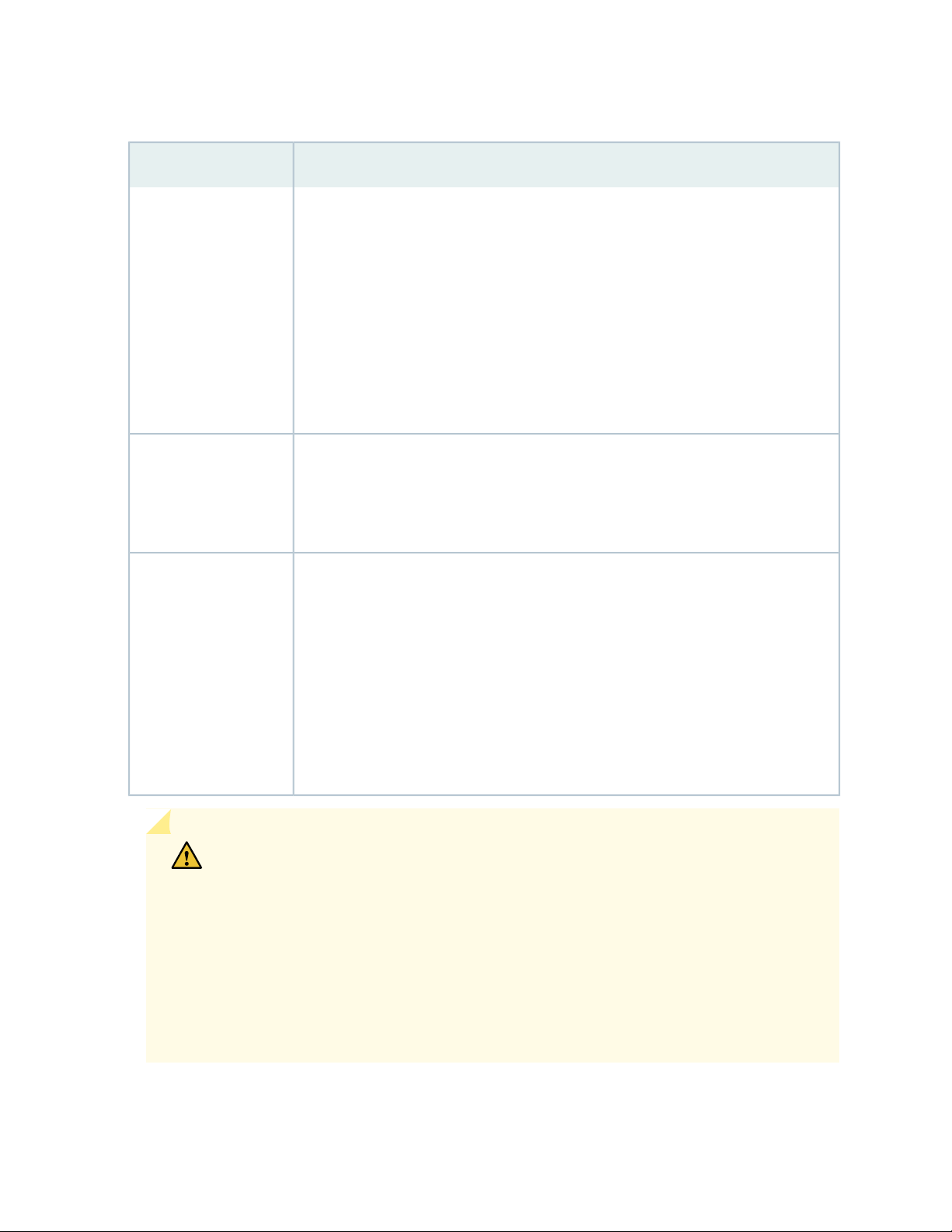
Table 14: Site Electrical Wiring Guidelines for the SRX550 Services Gateway
GuidelineSite Wiring Factor
50
Signaling limitations
Radio frequency
interference (RFI)
Electromagnetic
compatibility (EMC)
To ensure that signaling functions optimally:
Install wires correctly.
•
Improperly installed wires can emit radio interference.
Do not exceed the recommended distances or pass wires between buildings.
•
The potential for damage from lightning strikes increases if wires exceed recommended
distances or if wires pass between buildings.
Shield all conductors.
•
The electromagnetic pulse (EMP) caused by lightning can damage unshielded
conductors and destroy electronic devices.
To reduce or eliminate the emission of RFI from your site wiring:
Use twisted-pair cable with a good distribution of grounding conductors.
•
Use a high-quality twisted-pair cable with one ground conductor for each data signal
•
when applicable, if you must exceed the recommended distances.
Provide a properly grounded and shielded environment and use electrical
surge-suppression devices.
Strong sources of electromagnetic interference (EMI) can cause the following damage:
Destroy the signal drivers and receivers in the device.
•
Conduct power surges over the lines into the equipment, resulting in an electrical
•
hazard.
TIP: If your site is susceptible to problems with EMC, particularly from lightning or radio
transmitters, you might want to seek expert advice.
CAUTION: Some ports are designed for use as intrabuilding interfaces only (Type 2
or Type 4 ports, the battery return connection is to be treated as an Isolated DC return
(that is, DC-I), as defined in GR-1089-CORE) and require isolation from the exposed
OSP cabling. To comply the NEBS requirements and protect against lightening surges
and commercial power disturbances, the intrabuilding port(s) of the device MUST NOT
be metallically connected to interfaces that connect to the OSP or its wiring. The
intrabuilding port(s) of the device is suitable for connection to intrabuilding or
unexposed wiring or cabling only. The addition of primary protectors is not sufficient
protection to connect these interfaces metallically to OSP wiring.
Page 67

RELATED DOCUMENTATION
General Site Installation Guidelines for the SRX550 Services Gateway | 35
Maintaining the SRX550 Services Gateway Power Supply | 123
SRX550 Services Gateway Power Requirements | 54
SRX550 Services Gateway Environmental Specifications | 36
SRX550 Services Gateway Supported AC Power Cords
WARNING: The AC power cord for the services gateway is intended for use with the
services gateway only and not for any other use.
51
NOTE: In North America, AC power cords must not exceed 4.5 m (approximately 14.75 ft) in
length, to comply with National Electrical code (NEC) Section 400-8 (NFPA 75, 5-2.2) and 210-52,
and Canadian Electrical Code (CEC) Section 4-010(3).
Table 15 on page 51 provides power cord specifications, and Figure 13 on page 52 depicts the plug on
the AC power cord provided for each country or region.
Table 15: AC Power Cord Specifications
Plug StandardsElectrical SpecificationCountry
AS/NZ 3112-1993250 VAC, 10 A, 50 HzAustralia
250 VAC, 10 A, 50 HzChina
GB2099.1 1996 and
GB 1002 1996
(CH1-10P)
CEE (7) VII250 VAC, 10 A, 50 HzEurope (except Italy and United Kingdom)
CEI 23-16/VII250 VAC, 10 A, 50 HzItaly
Japan
JIS 8303125 VAC, 12 A, 50 or 60
Hz
NEMA 5-15125 VAC, 10 A, 60 HzNorth America
Page 68
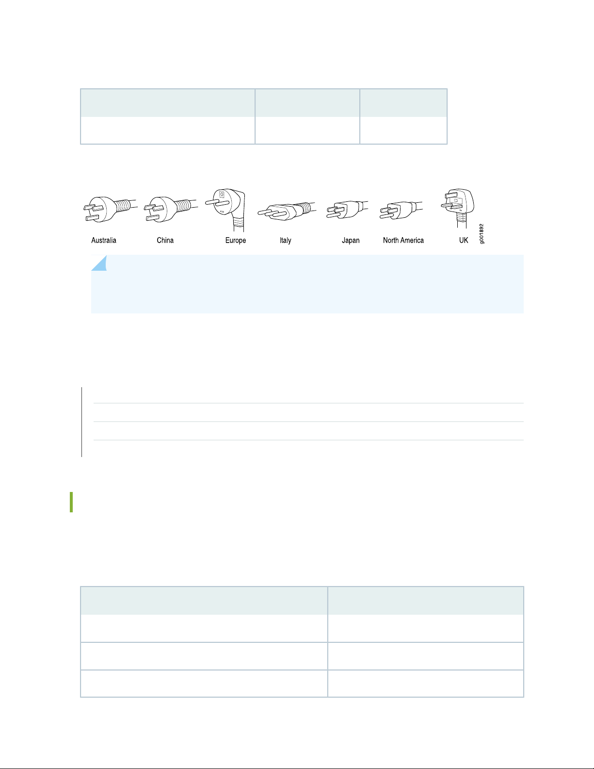
Table 15: AC Power Cord Specifications (continued)
Plug StandardsElectrical SpecificationCountry
BS 1363A250 VAC, 10 A, 50 HzUnited Kingdom
Figure 13: AC Plug Types
NOTE: Power cords and cables must not block access to services gateway components or drape
where people might trip on them.
52
RELATED DOCUMENTATION
SRX550 Services Gateway Power Supply | 28
Clearance Requirements for Airflow and Hardware Maintenance of the SRX550 Services Gateway | 45
SRX550 Services Gateway Electrical Wiring Guidelines | 49
Site Preparation Checklist for the SRX550 Services Gateway | 33
SRX550 Services Gateway AC Power Supply Electrical Specifications
The AC power supply electrical specifications for the SRX550 Services Gateway are listed in
Table 16 on page 52.
Table 16: AC Power Supply Electrical Specifications for the SRX550 Services Gateway
SpecificationPower Requirement
100 to 240 VACAC input voltage
50 to 60 HzAC input line frequency
7.6 to 3.8 AAC system current rating
Page 69
RELATED DOCUMENTATION
SRX550 Services Gateway Power Supply | 28
Clearance Requirements for Airflow and Hardware Maintenance of the SRX550 Services Gateway | 45
SRX550 Services Gateway Electrical Wiring Guidelines | 49
Site Preparation Checklist for the SRX550 Services Gateway | 33
SRX550 Services Gateway DC Power Cable Specifications
The DC power supply in slot 0 must be powered by dedicated power feeds derived from feed A, and the
DC power supply in slot 1 must be powered by dedicated power feeds derived from feed B. This
configuration provides the commonly deployed A/B feed redundancy for the system.
CAUTION: You must ensure that power connections maintain the proper polarity.
The power source cables might be labeled (+) and (–) to indicate their polarity. There
is no standard color coding for DC power cables. The color coding used by the external
DC power source at your site determines the color coding for the leads on the power
cables that attach to the terminal studs on each power supply.
53
WARNING: For field-wiring connections, use copper conductors only.
For other electrical safety information, see “SRX550 Services Gateway Electrical Wiring
Guidelines” on page 49.
CAUTION: Power cords and cables must not block access to services gateway
components or drape where people could trip on them.
Table 17 on page 53 summarizes the specifications for the power cable(s), which you must supply.
Table 17: DC Power Cable Specifications
Quantity and SpecificationCable Type
8 AWG, minimum 60°C wire, or as permitted by the local codePower
Page 70

RELATED DOCUMENTATION
SRX550 Services Gateway Power Supply | 28
Clearance Requirements for Airflow and Hardware Maintenance of the SRX550 Services Gateway | 45
SRX550 Services Gateway Electrical Wiring Guidelines | 49
Site Preparation Checklist for the SRX550 Services Gateway | 33
SRX550 Services Gateway DC Power Supply Electrical Specifications
The DC power supply electrical specifications for the SRX550 Services Gateway are listed in
Table 18 on page 54.
Table 18: DC Power Supply Electrical Specifications for the SRX550 Services Gateway
SpecificationPower Requirement
54
Operating range: –40 to –72 VDCDC input voltage
16 A at –48 VDCDC system current rating
RELATED DOCUMENTATION
SRX550 Services Gateway Power Supply | 28
Clearance Requirements for Airflow and Hardware Maintenance of the SRX550 Services Gateway | 45
SRX550 Services Gateway Electrical Wiring Guidelines | 49
Site Preparation Checklist for the SRX550 Services Gateway | 33
SRX550 Services Gateway Power Requirements
The electrical and power requirements for the SRX550 Services Gateway include factors you must consider
while planning the electrical wiring and power availability at your site. These requirements are covered in
the following topics:
Power specifications and requirements for the services gateway
•
Electrical wiring guidelines for the services gateway installation site
•
Page 71

Power, connection, and power cord specifications for the services gateway
•
Grounding guidelines and specifications for the services gateway
•
RELATED DOCUMENTATION
SRX550 Services Gateway Power Supply | 28
Clearance Requirements for Airflow and Hardware Maintenance of the SRX550 Services Gateway | 45
Site Preparation Checklist for the SRX550 Services Gateway | 33
SRX550 Services Gateway Electrical Wiring Guidelines | 49
Grounding the SRX550 Services Gateway | 77
55
Page 72
CHAPTER 11
Cable Specifications and Pinouts
IN THIS CHAPTER
Interface Cabling and Wiring Specifications for the SRX550 Services Gateway | 56
RJ-45 Connector Pinouts for the SRX550 Services Gateway Ethernet Port | 57
RJ-45 Connector Pinouts for the SRX550 Services Gateway Console Port | 58
Interface Cabling and Wiring Specifications for the SRX550 Services
56
Gateway
The network interfaces supported on the services gateway accept different kinds of network cables.
Table 19 on page 56 lists the specifications for the cables that connect to ports on the services gateway.
Table 19: Cable and Wire Specifications for Ports and Alarm Interfaces
Device
Receptacle
RJ-456 ft (1.83 m)One 6-ft (1.83-m) length with
Mini-B USB
Socket
RJ-45
autosensing
Console
Ethernet
RS-232 (EIA-232) serial
cable
USBUSB console
Category 5 cable or
equivalent suitable for
100Base-T operation
Maximum
LengthCable/Wire SuppliedCable SpecificationPort
DB-9/DB-9 connectors
6 ft (1.83 m)One 6-ft (1.83-m) length with
Mini-B and Type A plugs
328 ft (100 m)One 15-ft (4.57-m) length with
RJ-45/RJ-45 connectors
NOTE: The Auxiliary port is not supported on the SRX550 Services Gateway.
Page 73

RELATED DOCUMENTATION
RJ-45 Connector Pinouts for the SRX550 Services Gateway Ethernet Port | 57
RJ-45 Connector Pinouts for the SRX550 Services Gateway Console Port | 58
RJ-45 Connector Pinouts for the SRX550 Services Gateway Ethernet Port
The port on the front panel labeled ETHERNET is an autosensing 10/100-Mbps Ethernet RJ-45 receptacle
that accepts an Ethernet cable for connecting the services gateway to a management LAN (or other device
that supports out-of-band management). Table 20 on page 57 describes the RJ-45 connector pinouts for
the Ethernet port.
Table 20: RJ-45 Connector Pinouts for Services Gateway Ethernet Port
SignalPin
57
TX+1
TX-2
RX+3
Termination network4
Termination network5
RX-6
Termination network7
Termination network8
RELATED DOCUMENTATION
RJ-45 Connector Pinouts for the SRX550 Services Gateway Console Port | 58
Interface Cabling and Wiring Specifications for the SRX550 Services Gateway | 56
Page 74

RJ-45 Connector Pinouts for the SRX550 Services Gateway Console Port
The port on the front panel labeled CONSOLE is an autosensing 10/100-Mbps Ethernet RJ-45 receptacle
that accepts an RJ-45 cable for connecting the services gateway to a management LAN (or other device
that supports out-of-band management). Table 21 on page 58 describes the RJ-45 connector pinouts for
the console port.
Table 21: RJ-45 Connector Pinouts for the Services Gateway Console Port
DescriptionSignalPin
Request to SendRTS1
Data Terminal ReadyDTR2
Transmit DataTXD3
Signal GroundGround4
58
Signal GroundGround5
Receive DataRXD6
Data Set ReadyDSR/DCD7
Clear to SendCTS8
RELATED DOCUMENTATION
RJ-45 Connector Pinouts for the SRX550 Services Gateway Ethernet Port | 57
Interface Cabling and Wiring Specifications for the SRX550 Services Gateway | 56
Page 75

3
PART
Initial Installation and Configuration
Installation Overview | 60
Unpacking the Services Gateway | 64
Installing the Mounting Hardware | 67
Installing the Services Gateway | 69
Grounding the SRX550 Services Gateway | 76
Connecting the SRX550 Services Gateway to External Devices | 79
Providing Power to the SRX550 Services Gateway | 87
Performing Initial Configuration | 95
Page 76

CHAPTER 12
Installation Overview
IN THIS CHAPTER
Installation Overview for the SRX550 Services Gateway | 60
Required Tools and Parts for Installing the SRX550 Services Gateway | 61
Installation Instructions Warning | 62
SRX550 Services Gateway Autoinstallation Overview | 62
60
Installation Overview for the SRX550 Services Gateway
After you have prepared the site for installation and unpacked the SRX550 Services Gateway, you are
ready to install the device. It is important to proceed through the installation process in the following order:
1. Review the safety guidelines explained in General Electrical Safety Guidelines and Warnings.
2. Prepare the services gateway for installation as described in “Preparing the SRX550 Services Gateway
for Rack-Mount Installation” on page 67.
3. Install the services gateway as described in “Installing the SRX550 Services Gateway in a Rack” on
page 69.
4. Connect cables to external devices.
5. Connect the grounding cable as described in “Grounding the SRX550 Services Gateway” on page 77.
6. Power on the services gateway as described in “Powering On the SRX550 Services Gateway” on
page 93.
RELATED DOCUMENTATION
General Electrical Safety Guidelines and Warnings
Page 77

Preparing the SRX550 Services Gateway for Rack-Mount Installation | 67
Installing the SRX550 Services Gateway in a Rack | 69
Grounding the SRX550 Services Gateway | 77
Powering On the SRX550 Services Gateway | 93
Required Tools and Parts for Installing the SRX550 Services Gateway
To install the services gateway, you need the following tools and parts:
Phillips (+) screwdriver, number 2
•
Tie wrap
•
Electrostatic discharge (ESD) grounding wrist strap
•
61
RELATED DOCUMENTATION
Installation Overview for the SRX550 Services Gateway | 60
Installing the SRX550 Services Gateway in a Rack | 69
SRX550 Services Gateway Safety Requirements, Warnings, and Guidelines
Page 78

Installation Instructions Warning
WARNING: Read the installation instructions before you connect the services gateway
to a power source.
Waarschuwing Raadpleeg de installatie-aanwijzingen voordat u het systeem met de
voeding verbindt.
Varoitus Lue asennusohjeet ennen järjestelmän yhdistämistä virtalähteeseen.
Attention Avant de brancher le système sur la source d'alimentation, consulter les
directives d'installation.
Warnung Lesen Sie die Installationsanweisungen, bevor Sie das System an die
Stromquelle anschließen.
Avvertenza Consultare le istruzioni di installazione prima di collegare il sistema
all'alimentatore.
62
Advarsel Les installasjonsinstruksjonene før systemet kobles til strømkilden.
Aviso Leia as instruções de instalação antes de ligar o sistema à sua fonte de energia.
¡Atención! Ver las instrucciones de instalación antes de conectar el sistema a la red de
alimentación.
Varning! Läs installationsanvisningarna innan du kopplar systemet till dess
strömförsörjningsenhet.
RELATED DOCUMENTATION
SRX550 Services Gateway General Safety Guidelines and Warnings
Rack-Mounting Requirements and Warnings | 38
SRX550 Services Gateway Fire Safety Requirements and Fire Suppression Equipment
SRX550 Services Gateway Autoinstallation Overview
Autoinstallation provides automatic configuration for a new SRX550 Services Gateway that you connect
to the network and turn on, or for a services gateway configured for autoinstallation. The autoinstallation
Page 79

process begins whenever a services gateway is powered on and cannot locate a valid configuration file in
the CompactFlash. Typically, a configuration file is unavailable when a services gateway is powered on for
the first time or if the configuration file is deleted from the CompactFlash. The autoinstallation feature
enables you to deploy multiple services gateways from a central location in the network.
If you are setting up many services gateways, autoinstallation can help automate the configuration process
by loading configuration files onto new or existing devices automatically over the network. You can use
the CLI to configure a services gateway for autoinstallation. The J-Web interface does not include pages
for the autoinstallation feature.
For the autoinstallation feature to work, you must store one or more host-specific or default configuration
files on a configuration server in the network and have a service available—typically Dynamic Host
Configuration Protocol (DHCP)—to assign an IP address to the services gateway.
Autoinstallation begins automatically when you connect to the Ethernet port labeled 0/0 (interface
ge-0/0/0) on a new services gateway connected to the network and power on the services gateway. To
simplify the process, you can explicitly enable autoinstallation on a services gateway and specify a
configuration server, an autoinstallation interface, and a protocol for IP address acquisition.
63
NOTE: Autoinstallation is enabled on all ports of the services gateway. If you do not want to
use the autoinstallation feature, you must delete it using the CLI. For more information about
the autoinstallation feature, see the Initial Configuration for Security Devices.
RELATED DOCUMENTATION
Installation Overview for the SRX550 Services Gateway | 60
Required Tools and Parts for Installing the SRX550 Services Gateway | 61
Grounding the SRX550 Services Gateway | 77
SRX550 Services Gateway Basic Connectivity Overview | 95
Page 80

CHAPTER 13
Unpacking the Services Gateway
IN THIS CHAPTER
Unpacking the SRX550 Services Gateway | 64
Verifying Parts Received with the SRX550 Services Gateway | 65
Unpacking the SRX550 Services Gateway
64
Ensure that you have the following parts and tools available:
Phillips (+) screwdriver, number 2
•
1/2 in. (13 mm) open-end or socket wrench to remove bracket bolts from the shipping pallet
•
Blank panels to cover any slots not occupied by a component
•
The SRX550 Services Gateway is shipped in a cardboard carton and secured with foam packing material.
The carton also contains an accessory box and quick start instructions.
NOTE: The services gateway is maximally protected inside the cardboard carton. Do not unpack
it until you are ready to begin installation.
To unpack the SRX550 Services Gateway:
1. Move the cardboard carton to a staging area as close to the installation site as possible, where you
have enough room to remove the components from the chassis.
2. Position the cardboard carton with the arrows pointing up.
3. Carefully open the top of the cardboard carton.
4. Remove the foam covering the top of the services gateway.
5. Remove the accessory box.
Page 81

6. Verify the parts received against the lists in “Verifying Parts Received with the SRX550 Services
Gateway” on page 65.
7. Store the brackets and bolts inside the accessory box.
8. Save the shipping carton and packing materials in case you need to move or ship the services gateway
at a later time.
RELATED DOCUMENTATION
Preparing the SRX550 Services Gateway for Rack-Mount Installation | 67
Installation Overview for the SRX550 Services Gateway | 60
65
Verifying Parts Received with the SRX550 Services Gateway
The SRX550 Services Gateway shipment package contains a packing list. Check the parts in the shipment
against the items on the packing list. The packing list specifies the part numbers and carries a brief
description of each part in your order.
If any part on the packing list is missing, contact your customer service representative or contact Juniper
customer care from within the U.S. or Canada by telephone at 1-888-314-5822. For international-dial or
direct-dial options in countries without toll-free numbers, see
https://www.juniper.net/support/requesting-support.html.
A fully configured services gateway contains the chassis with installed components, listed in
Table 22 on page 65, and an accessory box, which contains the parts listed in Table 23 on page 66.
NOTE: The parts shipped with your services gateway can vary depending on the configuration
you ordered.
Table 22: Parts List for a Fully Configured SRX550 Services Gateway
supply slots, 6 10/100/1000 base-T ports, and 4 Gigabit Ethernet SFP ports. Includes blank covers
for GPIM slots (6 covers for GPIM slots), Mini-PIM slots, ACE slot, and power supply slots.
NOTE: The ACE slot is not used.
QuantityComponent
12U SRX550 Services Gateway chassis with 6 GPIM slots, 2 Mini-PIM slots, 1 ACE slot, 2 power
Page 82

Table 22: Parts List for a Fully Configured SRX550 Services Gateway (continued)
QuantityComponent
1Front-mount and mid-mount rack-mount kit
1Serial console cable with DB-9 and RJ-45 connectors
1USB console cable with Type-A and Mini-B USB plugs
1645 W AC power supply that provides: 390 W system power at 12 V; 255 W PoE power on a single
power supply, or with redundancy using the two power supply option; and 510 W PoE without
redundancy on two power supplies. Works with 90–264 VAC input.
NOTE: The shipment includes one power cord appropriate for your geographical location.
Two power supplies must be installed in the services gateway for redundancy. A second power supply
and additional power supplies are separately orderable and do not include the power cord. Additional
power cords must be ordered separately.
66
Table 23: Accessory/Upgrade Parts List for the SRX550 Services Gateway
RELATED DOCUMENTATION
QuantityPart
1Juniper Networks Product Warranty
1End User License Agreement
1Quick Start Guide
1Spare front-mount and mid-mount rack-mount kit
1Spare ACE slot blank cover
1Spare power supply slot blank cover
1645 W DC power supply with PoE support
Unpacking the SRX550 Services Gateway | 64
Preparing the SRX550 Services Gateway for Rack-Mount Installation | 67
Page 83

CHAPTER 14
Installing the Mounting Hardware
IN THIS CHAPTER
Preparing the SRX550 Services Gateway for Rack-Mount Installation | 67
Connecting the SRX550 Services Gateway to the Building Structure | 68
Preparing the SRX550 Services Gateway for Rack-Mount Installation
67
You can mount an SRX550 Services Gateway on four-post (telco) racks, enclosed cabinets, and open-frame
racks. Center-mount racks are not supported.
Before mounting the SRX550 Services Gateway in a rack:
Verify that the site meets the requirements described in “Site Preparation Checklist for the SRX550
•
Services Gateway” on page 33.
Verify that you have the following parts available in your rack-mounting kit for the SRX550 Services
•
Gateway:
Rack-mounting brackets
•
Eight mounting screws to attach the mounting brackets to the chassis of the services gateway
•
Four mounting screws to attach the mounting brackets to the rack rail
•
Verify that the racks or cabinets meet the specific requirements described in “SRX550 Services Gateway
•
Rack Size and Strength Requirements” on page 43.
Place the rack or cabinet in its permanent location, allowing adequate clearance for airflow and
•
maintenance, and secure it to the building structure. For more information, see “SRX550 Services Gateway
Cabinet Airflow Requirements” on page 48.
Remove the gateway chassis from the shipping carton. For unpacking instructions, see “Unpacking the
•
SRX550 Services Gateway” on page 64.
RELATED DOCUMENTATION
Page 84

SRX550 Services Gateway Cabinet Size and Clearance Requirements | 47
Installation Overview for the SRX550 Services Gateway | 60
Connecting the SRX550 Services Gateway to the Building Structure
Always secure the rack in which you are installing the SRX550 Services Gateway to the structure of the
building. If your geographical area is subject to earthquakes, bolt the rack to the floor. For maximum
stability, also secure the rack to ceiling brackets.
RELATED DOCUMENTATION
General Site Installation Guidelines for the SRX550 Services Gateway | 35
SRX550 Services Gateway Cabinet Size and Clearance Requirements | 47
68
SRX550 Services Gateway Rack Size and Strength Requirements | 43
Site Preparation Checklist for the SRX550 Services Gateway | 33
SRX550 Services Gateway Spacing of Mounting Bracket and Flange Holes | 44
Page 85
CHAPTER 15
Installing the Services Gateway
IN THIS CHAPTER
Installing the SRX550 Services Gateway in a Rack | 69
Installing an AC Power Supply on the SRX550 Services Gateway | 72
Installing a DC Power Supply on the SRX550 Services Gateway | 73
Installing the SRX550 Services Gateway in a Rack
69
You can front-mount the SRX550 Services Gateway in a rack. Many types of racks are acceptable, including
four-post (telco) racks, enclosed cabinets, and open-frame racks.
NOTE: If you are installing multiple devices in one rack, install the lowest one first and proceed
upward in the rack.
To install the services gateway in a rack:
1. Position a mounting bracket on each side of the chassis.
2. Use a Phillips (+) screwdriver, number 2 to install the screws that secure the mounting brackets to the
chassis. Use either the front mount position, as shown in Figure 14 on page 70, or the center mount
position as shown in Figure 15 on page 70.
Page 86
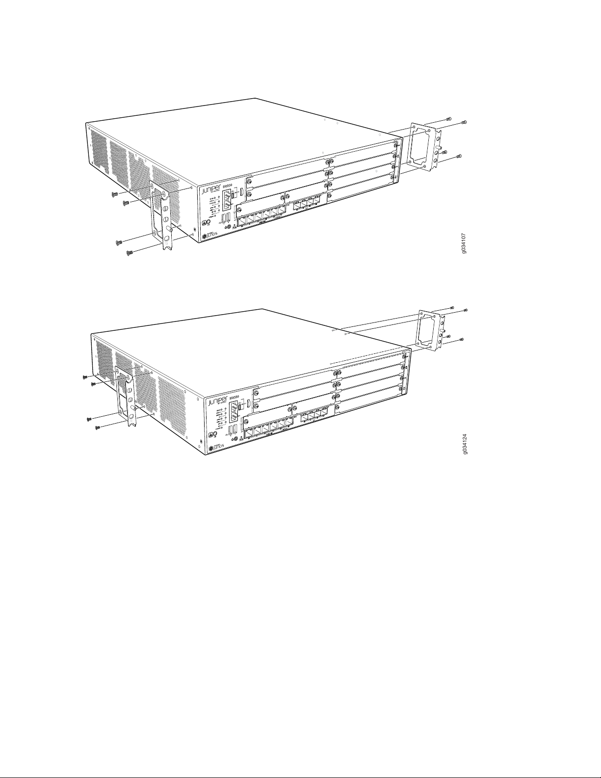
Figure 14: Installing the Rack Mount Brackets (Front Mount Position)
g034107
g034124
Figure 15: Installing the Rack Mount Brackets (Center Mount Position)
70
3. Have one person grasp the sides of the services gateway, lift it, and position it in the rack.
4. Align the bottom hole in each mounting bracket with a hole in each rack rail, making sure the chassis
is level.
5. Have a second person install a mounting screw into each of the two aligned holes. Use a Phillips (+)
screwdriver, number 2 to tighten the screws.
6. Install the second screw in each mounting bracket.
Page 87
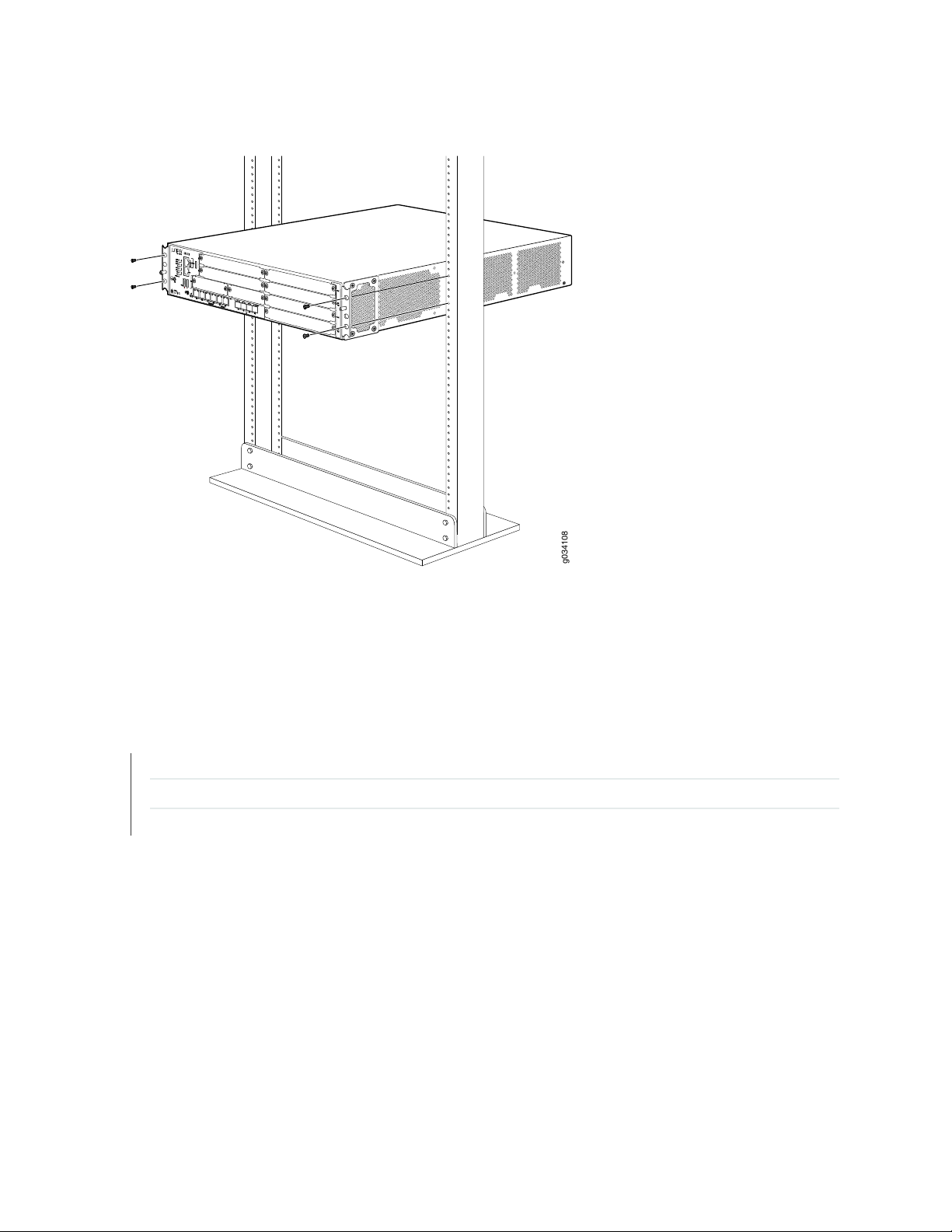
Figure 16: Installing the Services Gateway in the Rack (Front Mount Shown, Center Mount Similar)
g034108
71
7. Verify that the mounting screws on one side of the rack are aligned with the mounting screws on the
opposite side and that the services gateway is level.
RELATED DOCUMENTATION
Installation Overview for the SRX550 Services Gateway | 60
SRX550 Services Gateway Rack Size and Strength Requirements | 43
SRX550 Services Gateway Spacing of Mounting Bracket and Flange Holes | 44
Page 88
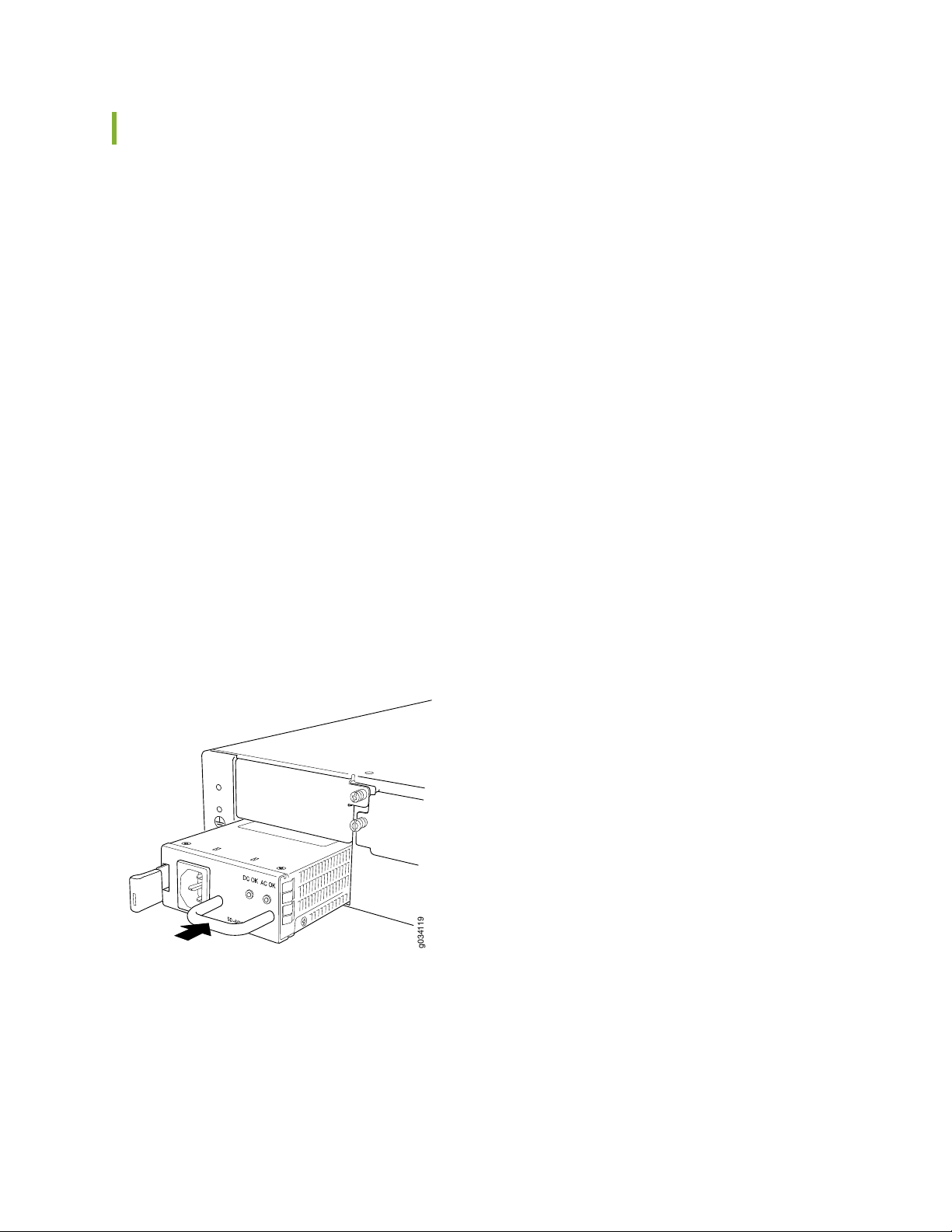
Installing an AC Power Supply on the SRX550 Services Gateway
g034119
To install an AC power supply:
1. Attach an electrostatic discharge (ESD) grounding strap to your bare wrist and connect the strap to
one of the ESD points on the chassis. For more information about ESD, see Preventing Electrostatic
Discharge Damage to the SRX550 Services Gateway.
2. Using both hands, slide the power supply straight into the chassis until the power supply is fully seated
in the chassis slot. The power supply faceplate should be flush with any adjacent power supply faceplate
(see Figure 17 on page 72).
3. Attach the power cord to the power supply.
4. Route the power cord along the cable restraint toward the left or right corner of the chassis. If they
are needed to hold the power cord in place, thread plastic cable ties, which you must provide, through
the openings on the cable restraint.
72
5. Attach the power cord to the AC power source, and switch on the dedicated facility circuit breaker for
the power supply. Follow the ESD and connection instructions for your site. If the power supply is
correctly installed and functioning normally, the POWER LED lights steadily.
Figure 17: Installing an AC Power Supply on the SRX550 Services Gateway
Page 89
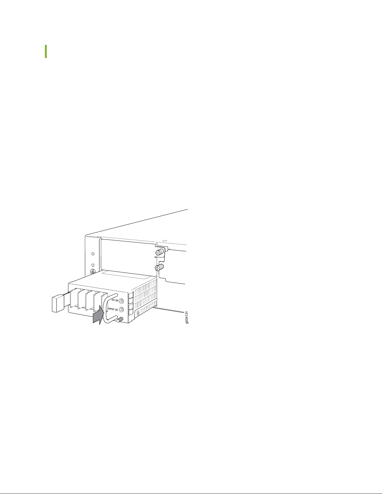
Installing a DC Power Supply on the SRX550 Services Gateway
g034121
To install a DC power supply:
1. Ensure that the voltage across the DC power source cable leads is 0 V and that there is no chance that
the cable leads might become active during installation. To ensure that all power is off, locate the circuit
breaker on the panel board that services the DC circuit, switch the circuit breaker to off position (O),
and tape the switch handle of the circuit breaker in the off position.
2. Attach an electrostatic discharge (ESD) grounding strap to your bare wrist and connect the strap to
one of the ESD points on the chassis. For more information about ESD, see Preventing Electrostatic
Discharge Damage to the SRX550 Services Gateway.
3. Orient the power supply so that the locking lever is on the left, as shown in Figure 18 on page 73.
Figure 18: Installing a DC Power Supply on an SRX550 Services Gateway
73
4. Using both hands, slide the power supply straight into the chassis until the power supply is fully seated
in the chassis slot. The power supply faceplate should be flush with any adjacent power supply faceplate.
5. Tighten the captive screws on the lower edge of the power supply faceplate.
6. Remove the clear plastic cover protecting the terminal studs on the faceplate.
Page 90

7. Verify that the DC power cables are correctly labeled before making connections to the power supply.
In a typical power distribution scheme where the return is connected to chassis ground at the battery
plant, you can use a multimeter to verify the resistance of the –48V and RTN DC cables to chassis
ground:
The cable with very large resistance (indicating an open circuit) to chassis ground will be –48V.
•
The cable with very low resistance (indicating a closed circuit) to chassis ground will be RTN.
•
CAUTION: You must ensure that power connections maintain the proper polarity.
The power source cables might be labeled (+) and (–) to indicate their polarity.
There is no standard color coding for DC power cables. The color coding used by
the external DC power source at your site determines the color coding for the leads
on the power cables that attach to the terminals on the power supply.
8. Connect DC power cables to the A+ and A- terminals:
74
a. Remove the screws and square washers from the A+ and A- terminals. Use a Phillips (+) screwdriver,
number 2. The square washers are permanently attached to the screws.
b. Secure each power cable lug to the appropriate terminal with a screw. Apply between 23 lb-in.
(2.6 Nm) and 25 lb-in. (2.8 Nm) of torque to each screw.
Secure the positive (+) DC source power cable lug to the A+ (return) terminal.
•
Secure the negative (–) DC source power cable lug to the A- (input) terminal.
•
Page 91
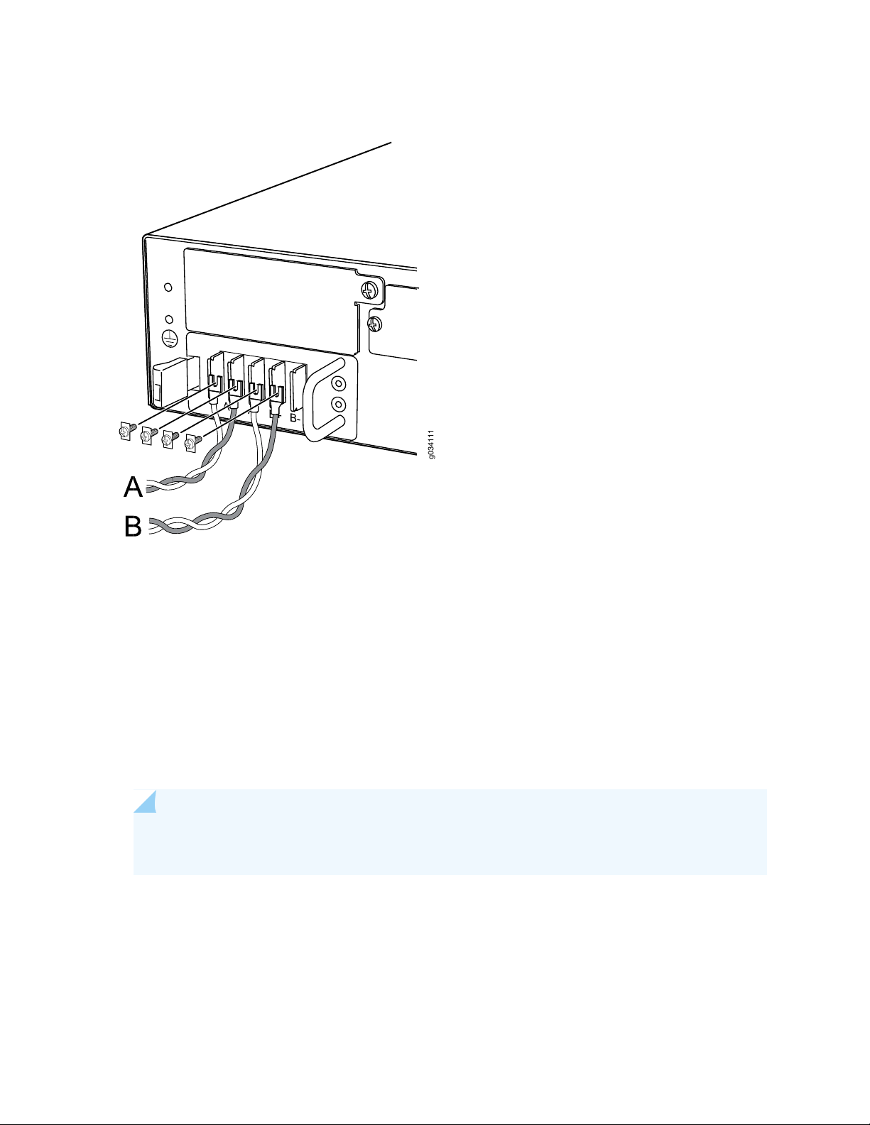
Figure 19: Connecting DC Power Cables
g034111
75
9. Replace the clear plastic cover over the terminal studs on the faceplate.
10. Verify that the power cables are connected correctly, that they are not touching or blocking access to
services gateway components, and that they do not drape where people could trip on them.
11. Remove the tape from the switch handle of the circuit breaker on the panel board that services the
DC circuit and switch the circuit breaker to the on position ( | ). Observe the status LEDs on the power
supply faceplate. If the power supply is correctly installed and functioning normally, the POWER LED
lights green steadily on the services gateway front panel.
NOTE: If more than one power supply is being installed, turn on all power supplies at the same
time.
Page 92

CHAPTER 16
Grounding the SRX550 Services Gateway
IN THIS CHAPTER
SRX550 Services Gateway Grounding Specifications | 76
Grounding the SRX550 Services Gateway | 77
SRX550 Services Gateway Grounding Specifications
76
To meet safety and electromagnetic interference (EMI) requirements and to ensure proper operation, the
SRX550 Services Gateway must be adequately grounded before power is connected. You must provide
a grounding lug to connect the services gateway to earth ground.
WARNING: Before services gateway installation begins, a licensed electrician must
attach a cable lug to the grounding and power cables that you supply. A cable with an
incorrectly attached lug can damage the services gateway (for example, by causing a
short circuit).
To ground the services gateway before connecting power, you connect the grounding cable to earth ground
and then attach the lug on the cable to the chassis grounding point, using the screw.
Table 24 on page 76 lists the specifications of the grounding cable used with the device.
Table 24: Grounding Cable Specifications for the SRX550 Services Gateway
SpecificationGrounding Requirement
14 AWG single-strand wire cableGrounding cable
Up to 25AAmperage of grounding cable
Ring-type, Panduit LCC6-10A-L lug, or equivalentGrounding lug
Page 93

RELATED DOCUMENTATION
Grounding the SRX550 Services Gateway | 77
Connecting the SRX550 Services Gateway to a DC Power Source | 90
Powering On the SRX550 Services Gateway | 93
Powering Off the SRX550 Services Gateway | 94
Grounding the SRX550 Services Gateway
You ground the services gateway by connecting a grounding cable to earth ground and then attaching it
to the chassis grounding points located on the right side of the device (if you are facing the front of the
chassis).
Ensure that you have the following parts and tools available:
Phillips (+) screwdrivers, numbers 1 and 2
•
77
Two M5 grounding screws
•
Grounding cables
•
Cable lugs (for example, Panduit LCC6-10A-L)
•
CAUTION: Before services gateway installation begins, a licensed electrician must
attach a cable lug to the grounding and power cables that you supply. A cable with an
incorrectly attached lug can damage the services gateway (for example, by causing a
short circuit).
To ground the services gateway:
1. Attach an electrostatic discharge (ESD) grounding strap to your bare wrist, and connect the strap to
the ESD point on the chassis. For more details, see Preventing Electrostatic Discharge Damage to the
SRX550 Services Gateway.
2. Ensure that all grounding surfaces are clean, free from accumulated dust or debris, and brought to a
bright finish before grounding connections are made.
NOTE: The surface of the grounding points are suitably plated for conductivity.
3. Connect the grounding cable to a proper earth ground.
Page 94

4. Place the grounding cable lugs over the grounding points (sized for M5 screws) on the left side of the
back panel.
5. Secure the grounding cable lugs to the grounding points, first with the washers, then with the screws.
6. Dress the grounding cable and verify that it does not touch or block access to the services gateway
components and that it does not drape where people could trip on it.
RELATED DOCUMENTATION
Preventing Electrostatic Discharge Damage to the SRX550 Services Gateway
Powering On the SRX550 Services Gateway | 93
Powering Off the SRX550 Services Gateway | 94
Organizing Interface Cables on the SRX550 Services Gateway | 79
78
SRX550 Services Gateway General Safety Guidelines and Warnings
Page 95

CHAPTER 17
Connecting the SRX550 Services Gateway to External Devices
IN THIS CHAPTER
Organizing Interface Cables on the SRX550 Services Gateway | 79
Connecting the Modem to the Console Port on the SRX550 Services Gateway | 80
Connecting to the SRX550 Services Gateway from the CLI with the USB Console Port | 81
Connecting the CLI at the User End for the SRX550 Services Gateway | 83
Configuring the Modem at the SRX550 Services Gateway End | 85
79
Organizing Interface Cables on the SRX550 Services Gateway
Arrange network cables as follows to prevent them from dislodging or developing stress points:
Secure cables so that they are not supporting their own weight as they hang to the floor.
•
Place excess cable out of the way in neatly coiled loops.
•
Use fasteners to maintain the shape of cable loops.
•
RELATED DOCUMENTATION
Preventing Electrostatic Discharge Damage to the SRX550 Services Gateway
Connecting the SRX550 Services Gateway to the AC Power Source | 87
Connecting the SRX550 Services Gateway to a DC Power Source | 90
Grounding the SRX550 Services Gateway | 77
Page 96

Connecting the Modem to the Console Port on the SRX550 Services Gateway
To connect the dial-up modem to the console port on the SRX550 Services Gateway:
1. Turn off power to the services gateway.
2. Turn off the power to the modem.
3. Plug one end of the Ethernet cable into the console port on the services gateway. (Figure 20 on page 80
shows the console cable connector).
Figure 20: Console Cable Connector
80
4. Plug the other end of the Ethernet cable into the RJ-45 to DB-9 serial port adapter.
NOTE: Most modems have an RS-232 DB-25 connector. You must separately purchase an
adapter to connect your modem to the RJ-45 to DB-9 adapter and Ethernet cable.
5. Connect the serial port adapter to a separately purchased DB-9 socket to DB-25 plug adapter or other
adapter appropriate for your modem.
6. Plug the modem adapter into the DB-25 connector on the modem.
7. Connect the modem to your telephone network.
8. Turn on the power to the modem.
9. Power on the services gateway by pressing the Power button on the front of the services gateway.
Verify that the POWER LED on the front panel turns green.
RELATED DOCUMENTATION
Page 97
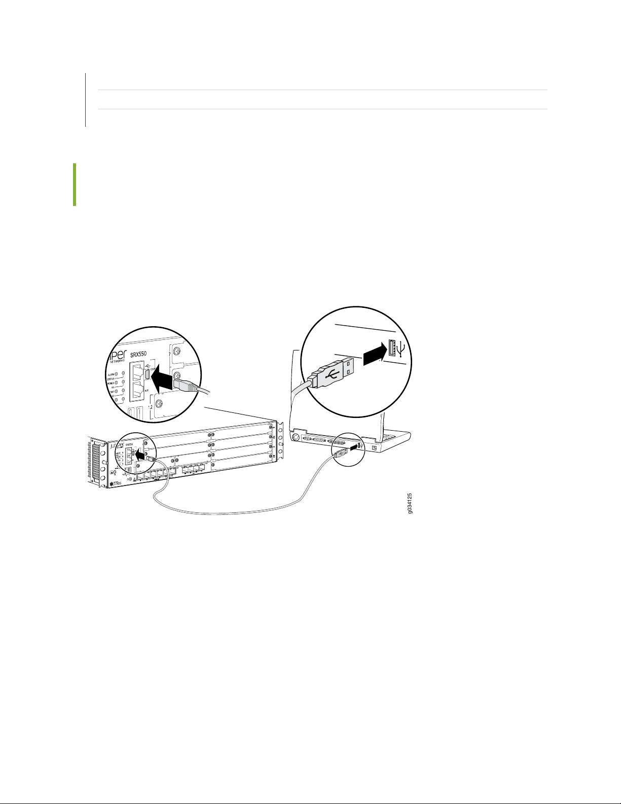
Connecting to the SRX550 Services Gateway from the CLI Remotely | 104
g034125
Configuring the Modem at the SRX550 Services Gateway End | 85
Connecting the CLI at the User End for the SRX550 Services Gateway | 83
Connecting to the SRX550 Services Gateway from the CLI with the USB Console Port
You can connect your management station to the USB console port on the services gateway and use the
CLI to configure the services gateway, as shown in Figure 21 on page 81.
Figure 21: Connecting to the USB Console Port on the SRX550 Services Gateway
81
To connect to the CLI using a local management device through the USB console port on the services
gateway:
Page 98

1. If you have not already done so, obtain the USB console driver software from the Juniper Networks
website or Silicon Labs website.
2. Install the USB console driver software by following these steps:
CAUTION: Install the USB console driver software before attempting to establish
a physical connection between the services gateway and the management device,
otherwise the connection will fail.
a. Copy and extract the .zip file to your local folder.
b. Double-click the .exe file. The installer window appears.
c. Click Install.
82
d. Click Continue Anyway on the next screen to complete the installation.
NOTE: If you chose STOP Installation at any time during the process then all or part of
the software will fail to install. In such a case, it is recommended that you uninstall the
USB console driver and then reinstall it.
e. Click OK when the installation is complete.
3. Plug the large end of the USB cable supplied with the services gateway into a USB port on the
management device (see Figure 21 on page 81).
4. Connect the other end of the USB cable to the USB console port on the services gateway (see
Figure 21 on page 81).
5. Start your asynchronous terminal emulation application (such as Microsoft Windows HyperTerminal),
and select the new COM port installed by the USB Console driver software. In most cases, this is the
highest-numbered COM port in the selection menu.
You can locate the COM port under Ports (COM & LPT) in Windows Device Manager after the driver
is installed and initialized. This might take several seconds.
6. Configure the port settings, as shown in Table 25 on page 83.
Page 99

Table 25: Port Settings
ValuePort Settings
9600Bits per second
8Data bits
NoneParity
1Stop bits
NoneFlow control
7. If you have not already done so, power on the services gateway by pressing the Power button on the
front of the services gateway. Verify that the POWER LED on the front panel turns green.
The terminal emulation screen on your management device displays the startup sequence. When the
services gateway has finished starting up, a login prompt appears.
83
8. Log in as the user root. No password is required at initial connection, but you must assign a root
password before committing any configuration settings.
RELATED DOCUMENTATION
Connecting to the SRX550 Services Gateway from the J-Web Interface | 98
Connecting to the SRX550 Services Gateway from the CLI Remotely | 104
Connecting the CLI at the User End for the SRX550 Services Gateway
To connect to the CLI through a dial-up modem connected to the console port on the SRX550 Services
Gateway:
1. Connect a modem at your remote location to a management device.
2. Start your asynchronous terminal emulation application (such as Microsoft Windows HyperTerminal)
on the management device.
3. Select the COM port to which the modem is connected (for example, COM1).
Page 100

4. Configure the port settings shown in Table 26 on page 84.
Table 26: Port Settings
ValuePort Settings
9600Bits per second
8Data bits
NoneParity
1Stop bits
NoneFlow control
5. In the HyperTerminal window, type AT.
84
For more information on the AT commands, see the Initial Configuration for Security Devices.
An OK response indicates that the modem can communicate successfully with the COM port on the
management device.
6. To dial the modem that is connected to the console port on the services gateway, type ATDT
remote-modem-number. For example, if the phone number of the modem connected to the console
port on the services gateway is 0019785551234, type ATDT 0019785551234.
The services gateway login prompt appears.
7. Log in as the user root. No password is required at initial connection, but you must assign a root
password before you commit any configuration settings.
RELATED DOCUMENTATION
Connecting to the SRX550 Services Gateway from the CLI Remotely | 104
Configuring the Modem at the SRX550 Services Gateway End | 85
Connecting the Modem to the Console Port on the SRX550 Services Gateway | 80
 Loading...