

Page 1

Junos®OS
MX Series 3D Universal Edge Routers Solutions
Guide
Release
13.1R1
Published: 2013-02-13
Copyright © 2013, Juniper Networks, Inc.
Page 2

Juniper Networks, Inc.
1194 North Mathilda Avenue
Sunnyvale, California 94089
USA
408-745-2000
www.juniper.net
This productincludes the Envoy SNMP Engine, developed by Epilogue Technology, an Integrated Systems Company. Copyright© 1986-1997,
Epilogue Technology Corporation. All rights reserved. This program and its documentation were developed at private expense, and no part
of them is in the public domain.
This product includes memory allocation software developed by Mark Moraes, copyright © 1988, 1989, 1993, University of Toronto.
This product includes FreeBSD software developed by the University of California, Berkeley, and its contributors. All of the documentation
and software included in the 4.4BSD and 4.4BSD-Lite Releases is copyrighted by the Regents of the University of California. Copyright ©
1979, 1980, 1983, 1986, 1988, 1989, 1991, 1992, 1993, 1994. The Regents of the University of California. All rights reserved.
GateD software copyright © 1995, the Regents of the University. All rights reserved. Gate Daemon was originated and developed through
release 3.0 by Cornell University and its collaborators. Gated is based on Kirton’s EGP, UC Berkeley’s routing daemon (routed), and DCN’s
HELLO routing protocol. Development of Gated has been supported in part by the National Science Foundation. Portions of the GateD
software copyright © 1988, Regents of the University of California. All rights reserved. Portions of the GateD software copyright © 1991, D.
L. S. Associates.
This product includes software developed by Maker Communications, Inc., copyright © 1996, 1997, Maker Communications, Inc.
Juniper Networks, Junos, Steel-Belted Radius, NetScreen, and ScreenOS are registered trademarks of Juniper Networks, Inc. in the United
States and other countries. The Juniper Networks Logo, the Junos logo, and JunosE are trademarks of Juniper Networks, Inc. All other
trademarks, service marks, registered trademarks, or registered service marks are the property of their respective owners.
Juniper Networks assumes no responsibility for any inaccuracies in this document. Juniper Networks reserves the right to change, modify,
transfer, or otherwise revise this publication without notice.
Products made or sold by Juniper Networks or components thereof might be covered by one or more of the following patents that are
owned by or licensed to Juniper Networks: U.S. Patent Nos. 5,473,599, 5,905,725, 5,909,440, 6,192,051, 6,333,650, 6,359,479, 6,406,312,
6,429,706, 6,459,579, 6,493,347, 6,538,518, 6,538,899, 6,552,918, 6,567,902, 6,578,186, and 6,590,785.
Junos®OS MX Series 3D Universal Edge Routers Solutions Guide
Release 13.1R1
Copyright © 2013, Juniper Networks, Inc.
All rights reserved.
Revision History
February 2013—Junos OS 13.1R1
The information in this document is current as of the date on the title page.
YEAR 2000 NOTICE
Juniper Networks hardware and software products are Year 2000 compliant. Junos OS has no known time-related limitations through the
year 2038. However, the NTP application is known to have some difficulty in the year 2036.
END USER LICENSE AGREEMENT
The Juniper Networks product that is the subject of this technical documentation consists of (or is intended for use with) Juniper Networks
software. Use of such software is subject to the terms and conditions of the End User License Agreement (“EULA”) posted at
http://www.juniper.net/support/eula.html. By downloading, installing or using such software, you agree to the terms and conditions
of that EULA.
Copyright © 2013, Juniper Networks, Inc.ii
Page 3

Abbreviated Table of Contents
About This Guide . . . . . . . . . . . . . . . . . . . . . . . . . . . . . . . . . . . . . . . . . . . . . . . . . xiii
Part 1 Overview
Chapter 1 Overview of Ethernet Solutions . . . . . . . . . . . . . . . . . . . . . . . . . . . . . . . . . . . . . . 3
Part 2 Basic Solutions for MX Series Routers
Chapter 2 Basic Layer 2 Features on MX Series Routers . . . . . . . . . . . . . . . . . . . . . . . . . . 21
Chapter 3 Virtual Switches . . . . . . . . . . . . . . . . . . . . . . . . . . . . . . . . . . . . . . . . . . . . . . . . . . 39
Chapter 4 VLANs Within Bridge Domain and VPLS Environments . . . . . . . . . . . . . . . . 43
Chapter 5 Bulk Administration of Layer 2 Features on MX Series Routers . . . . . . . . . . 63
Chapter 6 Dynamic Profiles for VLAN Interfaces and Protocols . . . . . . . . . . . . . . . . . . . 67
Chapter 7 MX Series Router as a DHCP Relay Agent . . . . . . . . . . . . . . . . . . . . . . . . . . . . 79
Chapter 8 MX Series Router in an ATM Ethernet Interworking Function . . . . . . . . . . . . 83
Part 3 Ethernet Filtering, Monitoring, and Fault Management Solutions
for MX Series Routers
Chapter 9 Layer 2 Firewall Filters . . . . . . . . . . . . . . . . . . . . . . . . . . . . . . . . . . . . . . . . . . . . . 101
Chapter 10 IEEE 802.1ag OAM Connectivity-Fault Management . . . . . . . . . . . . . . . . . . 109
Chapter 11 ITU-T Y.1731 Ethernet Frame Delay Measurements . . . . . . . . . . . . . . . . . . . . 125
Chapter 12 IEEE 802.3ah OAM Link-Fault Management . . . . . . . . . . . . . . . . . . . . . . . . . 143
Chapter 13 Ethernet Ring Protection . . . . . . . . . . . . . . . . . . . . . . . . . . . . . . . . . . . . . . . . . . . 151
Part 4 Index
Index . . . . . . . . . . . . . . . . . . . . . . . . . . . . . . . . . . . . . . . . . . . . . . . . . . . . . . . . . . . 185
iiiCopyright © 2013, Juniper Networks, Inc.
Page 4

Junos OS 13.1 MX Series 3D Universal Edge Routers Solutions Guide
Copyright © 2013, Juniper Networks, Inc.iv
Page 5

Table of Contents
About This Guide . . . . . . . . . . . . . . . . . . . . . . . . . . . . . . . . . . . . . . . . . . . . . . . . . xiii
Junos Documentation and Release Notes . . . . . . . . . . . . . . . . . . . . . . . . . . . . xiii
Objectives . . . . . . . . . . . . . . . . . . . . . . . . . . . . . . . . . . . . . . . . . . . . . . . . . . . . . xiv
Audience . . . . . . . . . . . . . . . . . . . . . . . . . . . . . . . . . . . . . . . . . . . . . . . . . . . . . . xiv
Supported Routing Platforms . . . . . . . . . . . . . . . . . . . . . . . . . . . . . . . . . . . . . . xv
Using the Indexes . . . . . . . . . . . . . . . . . . . . . . . . . . . . . . . . . . . . . . . . . . . . . . . xv
Using the Examples in This Manual . . . . . . . . . . . . . . . . . . . . . . . . . . . . . . . . . xv
Merging a Full Example . . . . . . . . . . . . . . . . . . . . . . . . . . . . . . . . . . . . . . . xv
Merging a Snippet . . . . . . . . . . . . . . . . . . . . . . . . . . . . . . . . . . . . . . . . . . . xvi
Documentation Conventions . . . . . . . . . . . . . . . . . . . . . . . . . . . . . . . . . . . . . . xvi
Documentation Feedback . . . . . . . . . . . . . . . . . . . . . . . . . . . . . . . . . . . . . . . xviii
Requesting Technical Support . . . . . . . . . . . . . . . . . . . . . . . . . . . . . . . . . . . . xviii
Self-Help Online Tools and Resources . . . . . . . . . . . . . . . . . . . . . . . . . . . xix
Opening a Case with JTAC . . . . . . . . . . . . . . . . . . . . . . . . . . . . . . . . . . . . . xix
Part 1 Overview
Chapter 1 Overview of Ethernet Solutions . . . . . . . . . . . . . . . . . . . . . . . . . . . . . . . . . . . . . . 3
Ethernet Terms and Acronyms . . . . . . . . . . . . . . . . . . . . . . . . . . . . . . . . . . . . . . . . . 3
Networking and Internetworking with Bridges and Routers . . . . . . . . . . . . . . . . . . . 6
Network Addressing at Layer 2 and Layer 3 . . . . . . . . . . . . . . . . . . . . . . . . . . . . . . . . 7
Networking at Layer 2: Benefits of Ethernet Frames . . . . . . . . . . . . . . . . . . . . . . . . 9
Networking at Layer 2: Challenges of Ethernet MAC Addresses . . . . . . . . . . . . . . . 10
Networking at Layer 2: Forwarding VLAN Tagged Frames . . . . . . . . . . . . . . . . . . . . 11
Networking at Layer 2: Forwarding Dual-Tagged Frames . . . . . . . . . . . . . . . . . . . . 13
Networking at Layer 2: Logical Interface Types . . . . . . . . . . . . . . . . . . . . . . . . . . . . 14
A Metro Ethernet Network with MX Series Routers . . . . . . . . . . . . . . . . . . . . . . . . . 15
Layer 2 Networking Standards . . . . . . . . . . . . . . . . . . . . . . . . . . . . . . . . . . . . . . . . . 17
Part 2 Basic Solutions for MX Series Routers
Chapter 2 Basic Layer 2 Features on MX Series Routers . . . . . . . . . . . . . . . . . . . . . . . . . . 21
Layer 2 Features for a Bridging Environment . . . . . . . . . . . . . . . . . . . . . . . . . . . . . . 21
Example Roadmap: Configuring a Basic Bridge Domain Environment . . . . . . . . . 22
Example Topology . . . . . . . . . . . . . . . . . . . . . . . . . . . . . . . . . . . . . . . . . . . . . . . 22
Example Scenario . . . . . . . . . . . . . . . . . . . . . . . . . . . . . . . . . . . . . . . . . . . . . . . 23
Example Configuration Summary . . . . . . . . . . . . . . . . . . . . . . . . . . . . . . . . . . 24
Example Step: Configuring Interfaces and VLAN Tags . . . . . . . . . . . . . . . . . . . . . . 24
Example Step: Configuring Bridge Domains . . . . . . . . . . . . . . . . . . . . . . . . . . . . . . 30
Example Step: Configuring Spanning Tree Protocols . . . . . . . . . . . . . . . . . . . . . . . 32
Example Step: Configuring Integrated Bridging and Routing . . . . . . . . . . . . . . . . . 34
vCopyright © 2013, Juniper Networks, Inc.
Page 6

Junos OS 13.1 MX Series 3D Universal Edge Routers Solutions Guide
Chapter 3 Virtual Switches . . . . . . . . . . . . . . . . . . . . . . . . . . . . . . . . . . . . . . . . . . . . . . . . . . 39
Layer 2 Features for a Switching Environment . . . . . . . . . . . . . . . . . . . . . . . . . . . . 39
Configuring Virtual Switches as Separate Routing Instances . . . . . . . . . . . . . . . . 40
Chapter 4 VLANs Within Bridge Domain and VPLS Environments . . . . . . . . . . . . . . . . 43
VLANs Within a Bridge Domain or VPLS Instance . . . . . . . . . . . . . . . . . . . . . . . . . 43
Packet Flow Through a Bridged Network with Normalized VLANs . . . . . . . . . . . . 44
Configuring a Normalized VLAN for Translation or Tagging . . . . . . . . . . . . . . . . . . 45
Implicit VLAN Translation to a Normalized VLAN . . . . . . . . . . . . . . . . . . . . . . 45
Sending Tagged or Untagged Packets over VPLS Virtual Interfaces . . . . . . . 46
Configuring a Normalized VLAN . . . . . . . . . . . . . . . . . . . . . . . . . . . . . . . . . . . 46
Configuring Learning Domains for VLAN IDs Bound to Logical Interfaces . . . . . . . 47
Example: Configuring a Provider Bridge Network with Normalized VLAN Tags . . . 47
Example: Configuring a Provider VPLS Network with Normalized VLAN Tags . . . . 51
Example: Configuring One VPLS Instance for Several VLANs . . . . . . . . . . . . . . . . 55
Chapter 5 Bulk Administration of Layer 2 Features on MX Series Routers . . . . . . . . . . 63
Bulk Configuration of VLANs and Bridge Domains . . . . . . . . . . . . . . . . . . . . . . . . . 63
Example: Configuring VLAN Translation with a VLAN ID List . . . . . . . . . . . . . . . . . 63
Example: Configuring Multiple Bridge Domains with a VLAN ID List . . . . . . . . . . . 64
Chapter 6 Dynamic Profiles for VLAN Interfaces and Protocols . . . . . . . . . . . . . . . . . . . 67
Dynamic Profiles for VPLS Pseudowires . . . . . . . . . . . . . . . . . . . . . . . . . . . . . . . . . 67
Example: Configuring VPLS Pseudowires with Dynamic Profiles—Basic
Solutions . . . . . . . . . . . . . . . . . . . . . . . . . . . . . . . . . . . . . . . . . . . . . . . . . . . . . . 68
VPLS Pseudowire Interfaces Without Dynamic Profiles . . . . . . . . . . . . . . . . . 68
VPLS Pseudowire Interfaces and Dynamic Profiles . . . . . . . . . . . . . . . . . . . . 69
CE Routers Without Dynamic Profiles . . . . . . . . . . . . . . . . . . . . . . . . . . . . . . . 70
CE Routers and Dynamic Profiles . . . . . . . . . . . . . . . . . . . . . . . . . . . . . . . . . . . 71
Example: Configuring VPLS Pseudowires with Dynamic Profiles—Complex
Solutions . . . . . . . . . . . . . . . . . . . . . . . . . . . . . . . . . . . . . . . . . . . . . . . . . . . . . . 72
Configuration of Routing Instance and Interfaces Without Dynamic
Profiles . . . . . . . . . . . . . . . . . . . . . . . . . . . . . . . . . . . . . . . . . . . . . . . . . . . . 73
Configuration of Routing Instance and Interfaces Using Dynamic
Profiles . . . . . . . . . . . . . . . . . . . . . . . . . . . . . . . . . . . . . . . . . . . . . . . . . . . . 74
Configuration of Tag Translation Using Dynamic Profiles . . . . . . . . . . . . . . . . 76
Chapter 7 MX Series Router as a DHCP Relay Agent . . . . . . . . . . . . . . . . . . . . . . . . . . . . 79
MX Series Router as a Layer 2 DHCP Relay Agent . . . . . . . . . . . . . . . . . . . . . . . . . 79
Example: Configuring DHCP Relay in a Bridge Domain VLAN Environment . . . . . 80
Example: Configuring DHCP Relay in a VPLS Routing Instance Environment . . . . 81
Chapter 8 MX Series Router in an ATM Ethernet Interworking Function . . . . . . . . . . . . 83
MX Series Router ATM Ethernet Interworking Function . . . . . . . . . . . . . . . . . . . . . 83
Example: Configuring MX Series Router ATM Ethernet Interworking . . . . . . . . . . . 85
Configuring Router PE2 with a Layer 2 Circuit . . . . . . . . . . . . . . . . . . . . . . . . . 86
Configuring Router PE2 with a Layer 2 Circuit over Aggregated Ethernet . . . 88
Configuring Router PE2 with a Remote Interface Switch . . . . . . . . . . . . . . . . . 91
Configuring Router PE2 with a Remote Interface Switch over Aggregated
Ethernet . . . . . . . . . . . . . . . . . . . . . . . . . . . . . . . . . . . . . . . . . . . . . . . . . . . 94
Copyright © 2013, Juniper Networks, Inc.vi
Page 7

Table of Contents
Part 3 Ethernet Filtering, Monitoring, and Fault Management Solutions
for MX Series Routers
Chapter 9 Layer 2 Firewall Filters . . . . . . . . . . . . . . . . . . . . . . . . . . . . . . . . . . . . . . . . . . . . . 101
Firewall Filters for Bridge Domains and VPLS Instances . . . . . . . . . . . . . . . . . . . . 101
Example: Configuring Policing and Marking of Traffic Entering a VPLS Core . . . . 102
Example: Configuring Filtering of Frames by MAC Address . . . . . . . . . . . . . . . . . 104
Example: Configuring Filtering of Frames by IEEE 802.1p Bits . . . . . . . . . . . . . . . 106
Example: Configuring Filtering of Frames by Packet Loss Priority . . . . . . . . . . . . 107
Chapter 10 IEEE 802.1ag OAM Connectivity-Fault Management . . . . . . . . . . . . . . . . . . 109
Ethernet Operations, Administration, and Maintenance . . . . . . . . . . . . . . . . . . . 109
Ethernet OAM Connectivity Fault Management . . . . . . . . . . . . . . . . . . . . . . . . . . 110
Example: Configuring Ethernet CFM over VPLS . . . . . . . . . . . . . . . . . . . . . . . . . . . 111
Example: Configuring Ethernet CFM on Bridge Connections . . . . . . . . . . . . . . . . . 118
Example: Configuring Ethernet CFM on Physical Interfaces . . . . . . . . . . . . . . . . . 122
Chapter 11 ITU-T Y.1731 Ethernet Frame Delay Measurements . . . . . . . . . . . . . . . . . . . . 125
Ethernet Frame Delay Measurements . . . . . . . . . . . . . . . . . . . . . . . . . . . . . . . . . . 125
Configuring MEP Interfaces to Support Ethernet Frame Delay Measurements . . 128
Triggering an Ethernet Frame Delay Measurements Session . . . . . . . . . . . . . . . . 129
Viewing Ethernet Frame Delay Measurements Statistics . . . . . . . . . . . . . . . . . . . 130
Example: Configuring One-Way Ethernet Frame Delay Measurements with
Single-Tagged Interfaces . . . . . . . . . . . . . . . . . . . . . . . . . . . . . . . . . . . . . . . . . 131
Example: Configuring Two-Way Ethernet Frame Delay Measurements with
Single-Tagged Interfaces . . . . . . . . . . . . . . . . . . . . . . . . . . . . . . . . . . . . . . . . 136
Example: Configuring Ethernet Frame Delay Measurements with Untagged
Interfaces . . . . . . . . . . . . . . . . . . . . . . . . . . . . . . . . . . . . . . . . . . . . . . . . . . . . . 140
Chapter 12 IEEE 802.3ah OAM Link-Fault Management . . . . . . . . . . . . . . . . . . . . . . . . . 143
Ethernet OAM Link Fault Management . . . . . . . . . . . . . . . . . . . . . . . . . . . . . . . . . 143
Example: Configuring Ethernet LFM Between Provider Edge and Customer
Edge . . . . . . . . . . . . . . . . . . . . . . . . . . . . . . . . . . . . . . . . . . . . . . . . . . . . . . . . . 144
Example: Configuring Ethernet LFM for CCC . . . . . . . . . . . . . . . . . . . . . . . . . . . . . 145
Example: Configuring Ethernet LFM for Aggregated Ethernet . . . . . . . . . . . . . . . 146
Example: Configuring Ethernet LFM with Loopback Support . . . . . . . . . . . . . . . . 148
Chapter 13 Ethernet Ring Protection . . . . . . . . . . . . . . . . . . . . . . . . . . . . . . . . . . . . . . . . . . . 151
Ethernet Ring Protection . . . . . . . . . . . . . . . . . . . . . . . . . . . . . . . . . . . . . . . . . . . . . 151
Ethernet Ring Protection Using Ring Instances for Load Balancing . . . . . . . . . . . 153
Example: Configuring Ethernet Ring Protection for MX Series Routers . . . . . . . . 154
Example Topology . . . . . . . . . . . . . . . . . . . . . . . . . . . . . . . . . . . . . . . . . . . . . . 154
Router 1 (RPL Owner) Configuration . . . . . . . . . . . . . . . . . . . . . . . . . . . . . . . 155
Router 2 Configuration . . . . . . . . . . . . . . . . . . . . . . . . . . . . . . . . . . . . . . . . . . . 157
Router 3 Configuration . . . . . . . . . . . . . . . . . . . . . . . . . . . . . . . . . . . . . . . . . . 158
Example: Configuring Load Balancing Within Ethernet Ring Protection for MX
Series Routers . . . . . . . . . . . . . . . . . . . . . . . . . . . . . . . . . . . . . . . . . . . . . . . . . 160
Example: Viewing Ethernet Ring Protection Status—Normal Ring Operation . . . 177
Example: Viewing Ethernet Ring Protection Status—Ring Failure Condition . . . . 179
viiCopyright © 2013, Juniper Networks, Inc.
Page 8

Junos OS 13.1 MX Series 3D Universal Edge Routers Solutions Guide
Part 4 Index
Index . . . . . . . . . . . . . . . . . . . . . . . . . . . . . . . . . . . . . . . . . . . . . . . . . . . . . . . . . . . . 185
Copyright © 2013, Juniper Networks, Inc.viii
Page 9

List of Figures
Part 1 Overview
Chapter 1 Overview of Ethernet Solutions . . . . . . . . . . . . . . . . . . . . . . . . . . . . . . . . . . . . . . 3
Figure 1: Native (Normal) and VLAN-Tagged Ethernet Frames . . . . . . . . . . . . . . . . 12
Figure 2: A Metro Ethernet Network . . . . . . . . . . . . . . . . . . . . . . . . . . . . . . . . . . . . . 15
Figure 3: A Metro Ethernet Network with MX Series Routers . . . . . . . . . . . . . . . . . 16
Figure 4: VLAN Tags on a Metro Ethernet Network . . . . . . . . . . . . . . . . . . . . . . . . . 16
Part 2 Basic Solutions for MX Series Routers
Chapter 2 Basic Layer 2 Features on MX Series Routers . . . . . . . . . . . . . . . . . . . . . . . . . . 21
Figure 5: Bridging Network with MX Series Routers . . . . . . . . . . . . . . . . . . . . . . . . 23
Figure 6: Designated, Root, and Alternate Ports . . . . . . . . . . . . . . . . . . . . . . . . . . . 34
Chapter 4 VLANs Within Bridge Domain and VPLS Environments . . . . . . . . . . . . . . . . 43
Figure 7: Provider Bridge Network Using Normalized VLAN Tags . . . . . . . . . . . . . 48
Figure 8: VLAN Tags and VPLS Labels . . . . . . . . . . . . . . . . . . . . . . . . . . . . . . . . . . 52
Figure 9: Many VLANs on One VPLS Instance . . . . . . . . . . . . . . . . . . . . . . . . . . . . 56
Chapter 8 MX Series Router in an ATM Ethernet Interworking Function . . . . . . . . . . . . 83
Figure 10: ATM Ethernet VLAN Interworking . . . . . . . . . . . . . . . . . . . . . . . . . . . . . . 83
Figure 11: ATM Ethernet VLAN Interworking Packet Structure . . . . . . . . . . . . . . . . 84
Figure 12: CCC-to-Stacked VLAN Translation . . . . . . . . . . . . . . . . . . . . . . . . . . . . . 84
Figure 13: ATM Ethernet VLAN Interworking . . . . . . . . . . . . . . . . . . . . . . . . . . . . . . 85
Part 3 Ethernet Filtering, Monitoring, and Fault Management Solutions
for MX Series Routers
Chapter 9 Layer 2 Firewall Filters . . . . . . . . . . . . . . . . . . . . . . . . . . . . . . . . . . . . . . . . . . . . . 101
Figure 14: Policing and Marking Traffic Entering a VPLS Core . . . . . . . . . . . . . . . . 102
Chapter 10 IEEE 802.1ag OAM Connectivity-Fault Management . . . . . . . . . . . . . . . . . . 109
Figure 15: Ethernet OAM with VPLS . . . . . . . . . . . . . . . . . . . . . . . . . . . . . . . . . . . . 112
Figure 16: Ethernet CFM over a Bridge Network . . . . . . . . . . . . . . . . . . . . . . . . . . . 118
Figure 17: Ethernet CFM on Physical Interfaces . . . . . . . . . . . . . . . . . . . . . . . . . . . 122
Chapter 11 ITU-T Y.1731 Ethernet Frame Delay Measurements . . . . . . . . . . . . . . . . . . . . 125
Figure 18: Ethernet OAM Overview . . . . . . . . . . . . . . . . . . . . . . . . . . . . . . . . . . . . . 126
Chapter 12 IEEE 802.3ah OAM Link-Fault Management . . . . . . . . . . . . . . . . . . . . . . . . . 143
Figure 19: Ethernet LFM Between Provider Edge and Customer Edge . . . . . . . . . 144
Figure 20: Ethernet LFM for CCC . . . . . . . . . . . . . . . . . . . . . . . . . . . . . . . . . . . . . . 145
Figure 21: Ethernet LFM for Aggregated Ethernet . . . . . . . . . . . . . . . . . . . . . . . . . . 147
ixCopyright © 2013, Juniper Networks, Inc.
Page 10

Junos OS 13.1 MX Series 3D Universal Edge Routers Solutions Guide
Figure 22: Ethernet LFM with Loopback Support . . . . . . . . . . . . . . . . . . . . . . . . . 148
Chapter 13 Ethernet Ring Protection . . . . . . . . . . . . . . . . . . . . . . . . . . . . . . . . . . . . . . . . . . . 151
Figure 23: Ethernet Ring Protection Example Nodes . . . . . . . . . . . . . . . . . . . . . . . 154
Figure 24: ERPwith Multiple Protection Instances Configured onThreeMX Series
Routers . . . . . . . . . . . . . . . . . . . . . . . . . . . . . . . . . . . . . . . . . . . . . . . . . . . . . . . 162
Copyright © 2013, Juniper Networks, Inc.x
Page 11

List of Tables
About This Guide . . . . . . . . . . . . . . . . . . . . . . . . . . . . . . . . . . . . . . . . . . . . . . . . . xiii
Table 1: Notice Icons . . . . . . . . . . . . . . . . . . . . . . . . . . . . . . . . . . . . . . . . . . . . . . . . xvii
Table 2: Text and Syntax Conventions . . . . . . . . . . . . . . . . . . . . . . . . . . . . . . . . . . xvii
Part 3 Ethernet Filtering, Monitoring, and Fault Management Solutions
for MX Series Routers
Chapter 11 ITU-T Y.1731 Ethernet Frame Delay Measurements . . . . . . . . . . . . . . . . . . . . 125
Table 3: Monitor Ethernet Delay Command Parameters . . . . . . . . . . . . . . . . . . . 129
Table 4: Show Ethernet Delay Command Parameters . . . . . . . . . . . . . . . . . . . . . . 131
Chapter 13 Ethernet Ring Protection . . . . . . . . . . . . . . . . . . . . . . . . . . . . . . . . . . . . . . . . . . . 151
Table 5: Components of the Network Topology . . . . . . . . . . . . . . . . . . . . . . . . . . 162
xiCopyright © 2013, Juniper Networks, Inc.
Page 12

Junos OS 13.1 MX Series 3D Universal Edge Routers Solutions Guide
Copyright © 2013, Juniper Networks, Inc.xii
Page 13

About This Guide
This preface provides the following guidelines for using the Junos®OS MX Series 3D
Universal Edge Routers Solutions Guide:
•
Junos Documentation and Release Notes on page xiii
•
Objectives on page xiv
•
Audience on page xiv
•
Supported Routing Platforms on page xv
•
Using the Indexes on page xv
•
Using the Examples in This Manual on page xv
•
Documentation Conventions on page xvi
•
Documentation Feedback on page xviii
•
Requesting Technical Support on page xviii
Junos Documentation and Release Notes
For a list of related Junos documentation, see
http://www.juniper.net/techpubs/software/junos/.
If the information in the latest release notes differs from the information in the
documentation, follow the Junos Release Notes.
To obtain the most current version of all Juniper Networks®technical documentation,
see the product documentation page on the Juniper Networks website at
http://www.juniper.net/techpubs/.
Juniper Networks supportsa technical bookprogram to publishbooks byJuniper Networks
engineers and subject matter experts with book publishers around the world. These
books go beyond the technical documentation to explore the nuances of network
architecture, deployment, and administration using the Junos operating system (Junos
OS) and Juniper Networks devices. In addition, the Juniper Networks Technical Library,
published in conjunction with O'Reilly Media, explores improving network security,
reliability, and availability using Junos OS configuration techniques. All the books are for
sale at technical bookstores and book outlets around the world. The current list can be
viewed at http://www.juniper.net/books.
xiiiCopyright © 2013, Juniper Networks, Inc.
Page 14

Junos OS 13.1 MX Series 3D Universal Edge Routers Solutions Guide
Objectives
This guide provides an overview of the Layer 2 features of the Junos OS and describes
how to configure the features to provide solutions to several network scenarios.
NOTE: For additional information about the Junos OS—either corrections to
or information thatmight havebeen omittedfrom this guide—see the software
release notes at http://www.juniper.net/ .
Audience
This guide is designed for network administrators who are configuring and monitoring
Layer 2 features of the Junos OS.
To use this guide, you need a broad understanding of networks in general, the Internet
in particular, networking principles, and network configuration. You must also be familiar
with one or more of the following Internet routing protocols:
•
Border Gateway Protocol (BGP)
•
Distance Vector Multicast Routing Protocol (DVMRP)
•
Intermediate System-to-Intermediate System (IS-IS)
•
Internet Control Message Protocol (ICMP) router discovery
•
Internet Group Management Protocol (IGMP)
•
Multiprotocol Label Switching (MPLS)
•
Open Shortest Path First (OSPF)
•
Protocol-Independent Multicast (PIM)
•
Resource Reservation Protocol (RSVP)
•
Routing Information Protocol (RIP)
•
Simple Network Management Protocol (SNMP)
Personnel operating the equipment must be trained and competent; must not conduct
themselves in a careless, willfully negligent, or hostile manner; and must abide by the
instructions provided by the documentation.
Copyright © 2013, Juniper Networks, Inc.xiv
Page 15

Supported Routing Platforms
For the Layer 2 features described in this manual, the Junos OS currently supports the
following routing platforms:
•
Juniper Networks MX Series 3D Universal Edge Routers
Using the Indexes
This reference contains a standard index with topic entries.
Using the Examples in This Manual
If you want to use the examples in this manual, you can use the load merge or the load
merge relative command. These commands cause the software to merge the incoming
configuration into the current candidate configuration. The example does not become
active until you commit the candidate configuration.
About This Guide
If the example configuration contains the top level of the hierarchy (or multiple
hierarchies), the example is a full example. In this case, use the load merge command.
If the example configuration does not start at the top level of the hierarchy, the example
is a snippet. In this case, use the load merge relative command. These procedures are
described in the following sections.
Merging a Full Example
To merge a full example, follow these steps:
1. From the HTML or PDF version of the manual, copy a configuration example into a
text file, save the file with a name, and copy the file to a directory on your routing
platform.
For example, copy the following configuration to a file andname the file ex-script.conf.
Copy the ex-script.conf file to the /var/tmp directory on your routing platform.
system {
scripts {
commit {
file ex-script.xsl;
}
}
}
interfaces {
fxp0 {
disable;
unit 0 {
family inet {
address 10.0.0.1/24;
}
}
}
xvCopyright © 2013, Juniper Networks, Inc.
Page 16

Junos OS 13.1 MX Series 3D Universal Edge Routers Solutions Guide
}
2. Merge the contents of the file into your routing platform configuration by issuing the
load merge configuration mode command:
[edit]
user@host# load merge /var/tmp/ex-script.conf
load complete
Merging a Snippet
To merge a snippet, follow these steps:
1. From the HTML or PDF version of the manual, copy a configuration snippet into a text
file, save the file with a name, and copy the file to a directory on your routing platform.
For example, copy the following snippet to a file and name the file
ex-script-snippet.conf. Copy the ex-script-snippet.conf file to the /var/tmp directory
on your routing platform.
commit {
file ex-script-snippet.xsl; }
2. Move to the hierarchy level that is relevant for this snippet by issuing the following
configuration mode command:
[edit]
user@host# edit system scripts
[edit system scripts]
3. Merge the contents of the file into your routing platform configuration by issuing the
load merge relative configuration mode command:
[edit system scripts]
user@host# load merge relative /var/tmp/ex-script-snippet.conf
load complete
For more information about the load command, see the CLI User Guide.
Documentation Conventions
Table 1 on page xvii defines notice icons used in this guide.
Copyright © 2013, Juniper Networks, Inc.xvi
Page 17
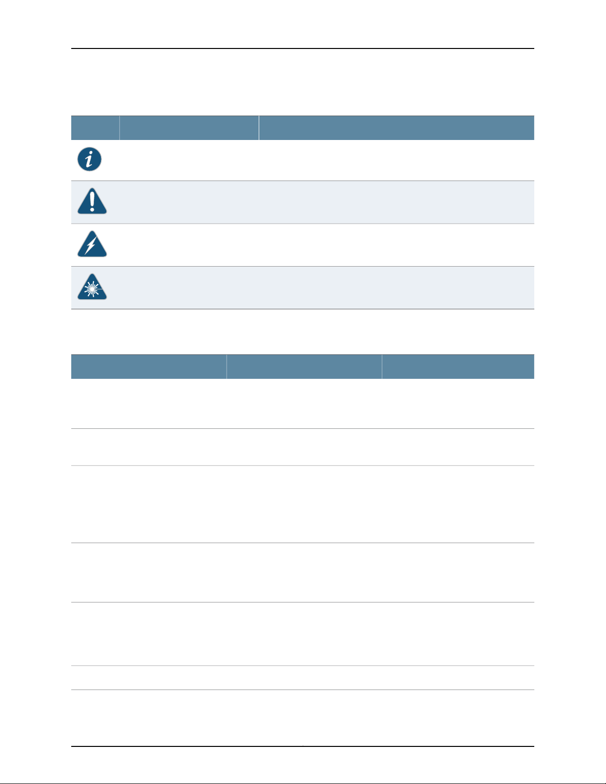
Table 1: Notice Icons
About This Guide
DescriptionMeaningIcon
Indicates important features or instructions.Informational note
Indicates a situation that might result in loss of data or hardware damage.Caution
Alerts you to the risk of personal injury or death.Warning
Alerts you to the risk of personal injury from a laser.Laser warning
Table 2 on page xvii defines the text and syntax conventions used in this guide.
Table 2: Text and Syntax Conventions
Represents text that you type.Bold text like this
Fixed-width text like this
Italic text like this
Italic text like this
Text like this
Represents output that appears on the
terminal screen.
•
Introduces or emphasizes important
new terms.
•
Identifies book names.
•
Identifies RFC and Internet draft titles.
Represents variables (options for which
you substitute a value) in commands or
configuration statements.
Represents names of configuration
statements, commands, files, and
directories;configurationhierarchy levels;
or labels on routing platform
components.
ExamplesDescriptionConvention
To enter configuration mode, type
theconfigure command:
user@host> configure
user@host> show chassis alarms
No alarms currently active
•
A policy term is a named structure
that defines match conditions and
actions.
•
Junos OS SystemBasics Configuration
Guide
•
RFC 1997, BGP Communities Attribute
Configure the machine’s domain name:
[edit]
root@# set system domain-name
domain-name
•
To configure a stub area, include the
stub statement at the[edit protocols
ospf area area-id] hierarchy level.
•
The console portis labeled CONSOLE.
stub <default-metric metric>;Enclose optional keywords or variables.< > (angle brackets)
xviiCopyright © 2013, Juniper Networks, Inc.
Page 18

Junos OS 13.1 MX Series 3D Universal Edge Routers Solutions Guide
Table 2: Text and Syntax Conventions (continued)
ExamplesDescriptionConvention
| (pipe symbol)
# (pound sign)
[ ] (square brackets)
Indention and braces ( { } )
; (semicolon)
J-Web GUI Conventions
Bold text like this
Indicates a choice betweenthe mutually
exclusivekeywords or variables on either
side of the symbol. The set of choices is
often enclosed in parentheses for clarity.
same lineas theconfiguration statement
to which it applies.
Enclose a variable for which you can
substitute one or more values.
Identify a level in the configuration
hierarchy.
Identifies a leaf statement at a
configuration hierarchy level.
Represents J-Web graphical user
interface (GUI) items you click or select.
broadcast | multicast
(string1 | string2 | string3)
rsvp { # Required for dynamic MPLS onlyIndicates a comment specified on the
community name members [
community-ids ]
[edit]
routing-options {
static {
route default {
nexthop address;
retain;
}
}
}
•
In the Logical Interfaces box, select
All Interfaces.
•
To cancel the configuration, click
Cancel.
> (bold right angle bracket)
Documentation Feedback
We encourage you to provide feedback, comments, and suggestions so that we can
improve the documentation. You can send your comments to
techpubs-comments@juniper.net, or fill out the documentation feedback form at
https://www.juniper.net/cgi-bin/docbugreport/ . If you are using e-mail, be sure to include
the following information with your comments:
•
Document or topic name
•
URL or page number
•
Software release version (if applicable)
Requesting Technical Support
Technical product support is available through the Juniper NetworksTechnical Assistance
Center (JTAC). If you are a customer with an active J-Care or JNASC support contract,
Separates levels in a hierarchy of J-Web
selections.
In the configuration editor hierarchy,
select Protocols>Ospf.
Copyright © 2013, Juniper Networks, Inc.xviii
Page 19

or are covered under warranty, and need postsales technical support, you can access
our tools and resources online or open a case with JTAC.
•
JTAC policies—For a complete understanding of our JTAC procedures and policies,
review the JTAC User Guide located at
http://www.juniper.net/us/en/local/pdf/resource-guides/7100059-en.pdf.
•
Product warranties—For product warranty information, visit
http://www.juniper.net/support/warranty/.
•
JTAC Hours of Operation —The JTAC centers have resources available 24 hours a day,
7 days a week, 365 days a year.
Self-Help Online Tools and Resources
For quick and easy problem resolution, Juniper Networks has designed an online
self-service portal called the Customer Support Center (CSC) that provides you with the
following features:
•
Find CSC offerings: http://www.juniper.net/customers/support/
About This Guide
•
Find product documentation: http://www.juniper.net/techpubs/
•
Find solutions and answer questions using our Knowledge Base: http://kb.juniper.net/
•
Download the latest versions of software and review release notes:
http://www.juniper.net/customers/csc/software/
•
Search technical bulletins for relevant hardware and software notifications:
https://www.juniper.net/alerts/
•
Join and participate in the Juniper Networks Community Forum:
http://www.juniper.net/company/communities/
•
Open a case online in the CSC Case Management tool: http://www.juniper.net/cm/
To verify service entitlement byproduct serial number, useour SerialNumber Entitlement
(SNE) Tool: https://tools.juniper.net/SerialNumberEntitlementSearch/
Opening a Case with JTAC
You can open a case with JTAC on the Web or by telephone.
•
Use the Case Management tool in the CSC at http://www.juniper.net/cm/.
•
Call 1-888-314-JTAC (1-888-314-5822 toll-free in the USA, Canada, and Mexico).
For international or direct-dial options in countries without toll-free numbers, visit us at
http://www.juniper.net/support/requesting-support.html
xixCopyright © 2013, Juniper Networks, Inc.
Page 20

Junos OS 13.1 MX Series 3D Universal Edge Routers Solutions Guide
Copyright © 2013, Juniper Networks, Inc.xx
Page 21

PART 1
Overview
•
Overview of Ethernet Solutions on page 3
1Copyright © 2013, Juniper Networks, Inc.
Page 22

Junos OS 13.1 MX Series 3D Universal Edge Routers Solutions Guide
Copyright © 2013, Juniper Networks, Inc.2
Page 23

CHAPTER 1
Overview of Ethernet Solutions
This chapter discusses the following topics:
•
Ethernet Terms and Acronyms on page 3
•
Networking and Internetworking with Bridges and Routers on page 6
•
Network Addressing at Layer 2 and Layer 3 on page 7
•
Networking at Layer 2: Benefits of Ethernet Frames on page 9
•
Networking at Layer 2: Challenges of Ethernet MAC Addresses on page 10
•
Networking at Layer 2: Forwarding VLAN Tagged Frames on page 11
•
Networking at Layer 2: Forwarding Dual-Tagged Frames on page 13
•
Networking at Layer 2: Logical Interface Types on page 14
•
A Metro Ethernet Network with MX Series Routers on page 15
•
Layer 2 Networking Standards on page 17
Ethernet Terms and Acronyms
Networking with a switch over Ethernet on a LAN is different than networking with a
router with IP over a wider area. Even the words used to talk about Ethernet networking
are different from those used in IP routing. This topic provides a list of all the terms and
acronyms used in the Junos OS Layer 2 Configuration Guide, as well terms that apply to
a complete network using Ethernet as a carrier technology.
•
802.1ad—The IEEE specification for “Q-in-Q” encapsulation and bridging of Ethernet
frames.
•
802.1ah—The IEEE specification for media access control (MAC) tunneling
encapsulation and bridging of Ethernet frames across a provided backbone-managed
bridge.
•
802.3ag—The IEEEspecification for a wide rangeof EthernetOperations, Administration,
and Maintenance (OAM) features. See also OAM, CFM, and ETH-DM.
•
802.3ah—The IEEE specification for link fault management (LFM), a method for OAM
of Ethernet links.
•
802.1Q—The IEEE specification for adding virtual local area network (VLAN) tags to
an Ethernet frame.
3Copyright © 2013, Juniper Networks, Inc.
Page 24

Junos OS 13.1 MX Series 3D Universal Edge Routers Solutions Guide
•
B–MAC—The backbone source and destination MAC address fields found in the IEEE
802.1ah provider MAC encapsulation header.
•
bridge—A network componentdefined by the IEEE that forwards frames from one LAN
segment or VLAN to another. The bridging function can be contained in a router, LAN
switch, or other specialized device. See also switch.
•
bridge domain—A set of logical ports that share the same flooding or broadcast
characteristics.As ina virtualLAN, abridge domainspans oneor moreports ofmultiple
devices. By default, each bridge domain maintains its own forwarding database of
MAC addresses learned frompackets received on ports belonging tothat bridge domain.
See also broadcast domain and VLAN.
•
B-TAG—A field defined in the IEEE 802.1ah provider MAC encapsulation header that
carries the backbone VLAN identifier information. The format of the B-TAG field is the
same as that of the IEEE 802.1ad S-TAG field. See also S-TAG.
•
B-VID—The specific VLAN identifier carried in a B-TAG.
•
CFM—Connectivity-fault management. Thepart ofEthernet OAM thatmonitors events
at levels above the physical level, as does LFM. See also OAM, LFM, and ETH-DM.
•
CIST—Common and Internal Spanning Tree. The single spanning tree calculated by
the spanning tree protocol (STP) and the rapid spanning tree protocol (RSTP) and
the logical continuation of that connectivity through multiple spanning tree (MST)
bridges and regions, calculated to ensure that all LANs in the bridged LAN are simply
and fully connected. See also MSTI.
•
ETH-DM—Ethernet Frame Delay Measurements. See also OAM, CFM, and Y.1731.
•
Ethernet—A term loosely applied to a family of LAN standards based on the original
proprietary Ethernet from DEC, Intel, and Xerox (DIX Ethernet), and the open
specifications developed by the IEEE 802.3 committee (IEEE 802.3 LANs). In practice,
few LANs comply completely with DIX Ethernet or IEEE 802.3.
•
IRB—Integrated bridging and routing. IRB provides simultaneous support for Layer 2
bridging and Layer 3 routing within the same bridge domain. Packets arriving on an
interface of the bridge domain are Layer 2 switched or Layer 3 routed based on the
destination MAC address. Packets addressed to the router's MAC address are routed
to other Layer 3 interfaces.
•
I-SID—The 24–bit service instance identifier field carried inside an I-TAG. The I-SID
defines the service instance to which the frame is mapped.
•
I-TAG—A field defined in the IEEE 802.1ah provider MAC encapsulation header that
carries the service instance information (I-SID) associated with the frame.
•
learning domain—A MAC addressdatabasewhere theMAC addresses areadded based
on the normalized VLAN tags.
•
LFM—Link fault management. A method used to detect problems on links and spans
on an Ethernet network defined in IEEE 802.3ah. See also OAM.
•
MSTI—Multiple Spanning Tree Instance. One of a number of spanning trees calculated
by MSTP within an MST region. The MSTI provides a simple and fully connected active
topology for frames classified as belonging to a VLAN that is mapped to the MSTI by
Copyright © 2013, Juniper Networks, Inc.4
Page 25

Chapter 1: Overview of Ethernet Solutions
the MST configuration table used by the MST bridges of that MST region. See also
CIST.
•
MSTP—Multiple Spanning Tree Protocol. A spanning-tree protocol used to prevent
loops in bridge configurations. Unlike other types of STPs, MSTP can block ports
selectively by VLAN. See also RSTP.
•
OAM—Operation, Administration, and Maintenance. A set of tools used to provide
management for links, device, and networks. See also LFM.
•
PBB—Provider backbone bridge.
•
Q-in-Q—See 802.1ad.
•
PBBN—Provider backbone bridged network.
•
RSTP—Rapid Spanning Tree Protocol. A spanning-tree protocol used to prevent loops
in bridge configurations. RSTP is not aware of VLANs and blocks ports at the physical
level. See also MSTP.
•
S-TAG—A field defined in the IEEE 802.1ad Q-in-Q encapsulation header that carries
the S-VLAN identifier information. See also B-TAG.
•
S-tagged service interface—The interface between a customer edge (CE) device and
the I-BEBor IB-BEB network components. Framespassed through this interface contain
an S-TAG field. See also B-tagged service interface.
•
S-VLAN—The specific service instance VLAN identifier carried inside the S-TAG field.
See also B-VID.
•
switch—A network device that attempts to perform as much of the forwarding task in
hardware as possible. The switch can function as a bridge (LAN switch), router, or
some other specialized device, and forwards frames, packets, or other data units. See
also bridge.
•
virtual switch—A routing instance that can contain one or more bridge domains.
•
VLAN—Virtual LAN. Defines a broadcast domain, a set of logical ports that share the
same floodingor broadcast characteristics. VLANs span one or more ports on multiple
devices. By default, each VLAN maintains its own Layer 2 forwarding database
containing MAC addresses learned from packets received on ports belonging to the
VLAN. See also bridge domain.
•
Y.1731—The international standard forEthernet Frame Delay Measurements (ETH-DM).
At this point, these acronyms and terms are just a bewildering array of letters and words.
It is the goal of this manual to make the contents of this list familiar and allow you to
place each of them in context and understand how they relate to each other. To do that,
a basic understanding of modern Ethernet standards and technology is necessary.
Related
Documentation
Ethernet Networking•
• Networking and Internetworking with Bridges and Routers on page 6
• Network Addressing at Layer 2 and Layer 3 on page 7
• Networking at Layer 2: Benefits of Ethernet Frames on page 9
5Copyright © 2013, Juniper Networks, Inc.
Page 26

Junos OS 13.1 MX Series 3D Universal Edge Routers Solutions Guide
• Networking at Layer 2: Challenges of Ethernet MAC Addresses on page 10
• Networking at Layer 2: Forwarding VLAN Tagged Frames on page 11
• Networking at Layer 2: Forwarding Dual-Tagged Frames on page 13
• Networking at Layer 2: Logical Interface Types on page 14
• A Metro Ethernet Network with MX Series Routers on page 15
• Layer 2 Networking Standards on page 17
Networking and Internetworking with Bridges and Routers
Traditionally, different hardware, software, and protocols have been used on LANs and
on networks that cover wider areas (national or global). A LAN switch is different than
a router, an Ethernet frame is different than an IP packet, and the methods used to find
destination MAC addresses are different thanthose usedto find destination IPaddresses.
This is because LANs basedon Ethernetwere intended fordifferent network environments
than networks based on IP. The Internet protocol suite (TCP/IP) was intended as an
internetworkingmethod toconnect local customer networks. Thelocal customer network
that a service provider's IP routers connected was usuallybased on some form of Ethernet.
This is why Ethernet and IP fit so well together: Ethernetdefines theLAN, and the Internet
protocols define how these LANs are connected.
More specifically, Ethernet LANs and IP networks occupy different layers of the Internet’s
TCP/IP protocol suite.Between sender and receiver, networks deal with thebottom three
layers of the model: the physical layer (Layer 1), the data link or MAC layer (Layer 2), and
the network layer (Layer 3).
NOTE: These layers are also found in the Open Systems Interconnect
Reference Model (OSI-RM); however, in this chapter they are applied to the
TCP/IP protocol suite.
All digital networks ultimately deal with zeroes and ones, and the physical layer defines
bit representation on the media. Physical layer standards alsodefine mechanical aspects
of the network, such as electrical characteristics or connector shapes,functional aspects
such as bit sequence and organization, and so on. The physical layer only “spits bits” and
has very little of the intelligence required to implement a complete network. Devices that
connect LAN segments at the physical layer are called hubs, and all bits that appear on
one port of the hub are also sent out on the other ports. This also means that bad bits
that appear on one LAN segment are propagated to all other LAN segments.
Above the physical layer, the data link layer defines the first-order bit structure, or frame,
for the network type. Also loosely called the MAC layer (technically, the MAC layer is a
sublayer required only on LANs), Layer 2 sends and receives frames. Frames are the last
things that bits were before they left the sender and the first things that bits become
when they arrive on an interface. Because frames have a defined structure, unlike bits,
frames can be used for error detection, control plane activities (not all frames must carry
user data: some frames are used by the network to control the link), and so forth. LAN
Copyright © 2013, Juniper Networks, Inc.6
Page 27

Chapter 1: Overview of Ethernet Solutions
segments can be linked at the frame level, and these devices are called bridges. Bridges
examine arriving frames and decide whether to forward them on an interface. All bridges
today are called learning bridges because they can find out more about the network than
could older bridges that were less intelligent devices. Bridges learn much about the LAN
segments they connect to from protocols like those in the Spanning Tree Protocol (STP)
family.
The network layer (Layer 3) is the highest layer used by network nodes to forward traffic
as part of the data plane. On the Internet, the network layer is the IP layer and can run
either IPv4 or IPv6, which are independent implementations of the same functions. The
IP layer defines the structure and purpose of the packet, which is in turn the content of
the frame at Layer 2. As expected, LAN segments (which now form perfectly functional
networks on their own at the frame level) can be linked at the network layer, and in fact
that is one of the major functions of IP. Devices that link LANs at the network layer are
called routers, and IP routers are the network nodes of the Internet.
Related
Documentation
Ethernet Networking•
• Ethernet Terms and Acronyms on page 3
• Network Addressing at Layer 2 and Layer 3 on page 7
• Networking at Layer 2: Benefits of Ethernet Frames on page 9
• Networking at Layer 2: Challenges of Ethernet MAC Addresses on page 10
• Networking at Layer 2: Forwarding VLAN Tagged Frames on page 11
• Networking at Layer 2: Forwarding Dual-Tagged Frames on page 13
• Networking at Layer 2: Logical Interface Types on page 14
• A Metro Ethernet Network with MX Series Routers on page 15
• Layer 2 Networking Standards on page 17
Network Addressing at Layer 2 and Layer 3
The Internet is a global, public network with IP subnets connected by routers and
exchanging packets. Can a global, public network consist of Ethernet LANs connected
by bridges and exchanging frames? Yes, it can, but there are several differences that
must be addressed before Ethernet can function as effectively as IP in the metropolitan
area (Metro Ethernet), let alone globally. One of the key differences is the addresses
used by Layer 2 frames and Layer 3 packets.
Both Ethernet and IP use globally unique network addresses that can be used as the
basis for a truly global network. Ethernet MAC addresses come from the IEEE and IP
subnet addresses come from various Internet authorities. (IP also employs a naming
convention absent in Ethernet, but we'll ignore that in this discussion.) The keydifferences
in how these addresses are assigned make all the difference when it comes to the basic
functions of a bridge as opposed to a router.
7Copyright © 2013, Juniper Networks, Inc.
Page 28

Junos OS 13.1 MX Series 3D Universal Edge Routers Solutions Guide
NOTE: The opposite of a “globally unique network address” is the “locally
significant connection identifier” which connects two endpoints on a network.
For example, MPLS labels such as 1000001 can repeat in a network, but a
public IP address can appear on the Internet in only one place at a time
(otherwise it is an error).
All devices on LANs that are attached to the Internet have both MAC layer and IP
addresses. Frames and packets contain both source and destination addresses in their
headers. In general:
•
MAC addresses are 48 bits long. The first 24 bits are assigned by the IEEE and form
the organizationally unique identifier (OUI) of the manufacturer or vendor requesting
the address. The last 24 bits form the serial number of the LAN interface cards and
their uniqueness must be enforced by the company (some companies reuse numbers
of bad or returned cards while others do not).
•
IPv4 addresses are 32 bits long. A variable number of the beginning bits are assigned
by an Internet authority and represent a subnet located somewhere in the world. The
remaining bits are assigned locally and, when joined to the network portion of the
address, uniquely identify some host on a particular network.
•
IPv6 addresses are 128 bits long. Although there are significant differences, for the
purposes of this discussion, it is enough to point out that there is also a network and
host portion to an IPv6 address.
Note that MAC addresses are mainly organized by manufacturer and IP addresses are
organized by network, which is located in a particular place. Therefore, the IP address
can easily be used by routers for a packet's overall direction (for example, “192.168.27.48
is west of here”). However, the MAC addresses on a vendor's interface cards can end up
anywhere in the world, and often do. Consider a Juniper Networks router as a simple
example.Every Ethernet LAN interface on the router thatsends or receives packets places
them inside Ethernet frames with MAC addresses. All of these interfaces share the initial
24 bitsassigned to Juniper Networks. Two might differ onlyin one digitfrom one interface
to another. Yet the routers containing these MAC interfaces could be located on opposite
sides of the world.
An Internet backbone router only needs a table entry for every network (not host) in the
world. Most other routers only have a portion of this full table, and a default route for
forwarding packets with no entries in their table. In contrast, to perform the same role,
a bridge would need one table entry for every LAN interface, on host or bridge, in the
world. This is hard enough to do for Ethernets that span a metropolitan area, let alone
the entire world.
NOTE: There are other reasons that Ethernet would be hard-pressed to
become a truly global network, including the fact that MAC addresses do not
often have names associated with them while IP addresses do (for example,
192.168.27.48 might be host48.accounting.juniper.net). This section addresses
only the address issues.
Copyright © 2013, Juniper Networks, Inc.8
Page 29

Chapter 1: Overview of Ethernet Solutions
Related
Documentation
Ethernet Networking•
• Ethernet Terms and Acronyms on page 3
• Networking and Internetworking with Bridges and Routers on page 6
• Networking at Layer 2: Benefits of Ethernet Frames on page 9
• Networking at Layer 2: Challenges of Ethernet MAC Addresses on page 10
• Networking at Layer 2: Forwarding VLAN Tagged Frames on page 11
• Networking at Layer 2: Forwarding Dual-Tagged Frames on page 13
• Networking at Layer 2: Logical Interface Types on page 14
• A Metro Ethernet Network with MX Series Routers on page 15
• Layer 2 Networking Standards on page 17
Networking at Layer 2: Benefits of Ethernet Frames
In spite of the difficulties of using a bridge to perform the network role of a router, many
vendors, customers, and service providers are attracted to the idea of using Ethernet in
as many places of their networks as possible.
The perceived benefits of Ethernet are:
•
Most information starts and ends inside Ethernet frames. Today, this applies to data,
as well as voice (for example, VoIP) and video (for example, Web cams).
•
Ethernet frames have all the essentials for networking, such as globally unique source
and destination addresses, error control, and so on.
•
Ethernet frames can carry any kind of packet. Networking at Layer 2 is protocol
independent (independent of the Layer 3 protocol). Layer 2 networks work for IP
packets and all other Layer 3 protocols.
•
More layers added to the Ethernet frame only slow the networking process down
(“nodal processing delay”).
•
Adjunct networking features such as class of service (CoS) or multicasting can be
added to Ethernet as readily as IP networks.
If more of the end-to-end transfer of information from a source to a destination can be
done in the form of Ethernet frames, more of the benefits of Ethernet can be realized on
the network. Networking at Layer 2 can be a powerful adjunct to IP networking, but it is
not usually a substitute for IP networking.
9Copyright © 2013, Juniper Networks, Inc.
Page 30

Junos OS 13.1 MX Series 3D Universal Edge Routers Solutions Guide
NOTE: Networking at the frame level says nothing about the presence or
absence of IP addressesat the packet level. Almost all ports, links, and devices
on a network of LAN switches still have IP addresses, just as do all the source
and destination hosts. There are many reasons for the continued need for IP,
not the least of which is the need to manage the network. A device or link
without an IP address is usually invisible to most management applications.
Also, utilities such as remote access for diagnostics, file transfer of
configurations and software, and so on cannot run without IP addresses as
well as MAC addresses.
Related
Documentation
Ethernet Networking•
• Ethernet Terms and Acronyms on page 3
• Networking and Internetworking with Bridges and Routers on page 6
• Network Addressing at Layer 2 and Layer 3 on page 7
• Networking at Layer 2: Challenges of Ethernet MAC Addresses on page 10
• Networking at Layer 2: Forwarding VLAN Tagged Frames on page 11
• Networking at Layer 2: Forwarding Dual-Tagged Frames on page 13
• Networking at Layer 2: Logical Interface Types on page 14
• A Metro Ethernet Network with MX Series Routers on page 15
• Layer 2 Networking Standards on page 17
Networking at Layer 2: Challenges of Ethernet MAC Addresses
If a networked Layer 2 device such as a bridge or LAN switch could contain a list of all
known MAC addresses, then the network node could function in much the same way as
a router, forwarding frames instead of packets hop-by-hop through the network from
source LAN to destination LAN. However, the MAC address is much larger than the IPv4
address currently used on the Internet backbone (48 bits compared to the 32 bits of
IPv4).
Related
Documentation
This poses problems. Also, because the MAC address has no “network organization” like
the IPv4or IPv6 address, anLayer 2network node must potentially store every conceivable
MAC address in memory for next-hop table lookups. Instead of tables of about 125,000
entries, every Layer 2 network node would have to store millions of entries (for example,
24 bits, the potential NIC production from one Ethernet vendor, would require a table of
more than 16 million entries).
Ethernet Networking•
• Ethernet Terms and Acronyms on page 3
• Networking and Internetworking with Bridges and Routers on page 6
• Network Addressing at Layer 2 and Layer 3 on page 7
Copyright © 2013, Juniper Networks, Inc.10
Page 31

• Networking at Layer 2: Benefits of Ethernet Frames on page 9
• Networking at Layer 2: Forwarding VLAN Tagged Frames on page 11
• Networking at Layer 2: Forwarding Dual-Tagged Frames on page 13
• Networking at Layer 2: Logical Interface Types on page 14
• A Metro Ethernet Network with MX Series Routers on page 15
• Layer 2 Networking Standards on page 17
Networking at Layer 2: Forwarding VLAN Tagged Frames
VLAN tags were not developed as a way to limit network node table entries. They were
originally invented to allow LAN switches to distinguish between physical groups of LAN
ports and logical groups of LAN ports. In other words, there was a need to configure a
LAN switch (or group of local LAN switches) to know that “these ports belong to VLAN
A” and “these ports belong to VLAN B.”
Chapter 1: Overview of Ethernet Solutions
This was important because of how all LANs, not just Ethernet, work at the frame level.
Lots of frames on a LAN are broadcast to all stations (hosts and network nodes) on the
LAN segment. Also, multicasting works by flooding traffic within the VLAN. The stations
that received broadcast frames form the broadcast domain of the LAN. Only Ethernet
frames belonging to same broadcast domain are forwarded out certain ports on the LAN
switch. This prevents broadcaststorms and isolates routine control frames onto the LAN
segment where they make the most sense.
The VLAN tag was invented to distinguish among different VLAN broadcast domains on
a group of LAN switches. The VLAN tag is a two-byte field inserted between the source
MAC address and the Ethertype (or length) field in an Ethernet frame. Another two-byte
field, the Tag Protocol Identifier (TPI or TPID), precedes the VLAN tag field.
Two fields were necessary to hold one piece of information, the VLAN tag, to enable
receiversto distinguish between untagged or plain Ethernet frames and those containing
VLAN tags. A mechanism wasrequired to differentiate between theEthertype andlength
field for the untagged case and to distinguish among VLAN tag, Ethertype, and length
field for the tagged case. The answer was to constrain the TPID field to values that were
not valid Ethernet frame lengths or defined as valid Ethertypes. The first VLANtag added
to an Ethernet frame is always indicated by a TPID value of 0x8100. This is not the VLAN
identifier, which appears in the next two bytes.
In Figure 1 on page 12, a native or normal Ethernet frame is compared to a VLAN-tagged
Ethernet frame. The lengths of each field, in bytes, is shown next to the field name.
11Copyright © 2013, Juniper Networks, Inc.
Page 32

Junos OS 13.1 MX Series 3D Universal Edge Routers Solutions Guide
Figure 1: Native (Normal) and VLAN-Tagged Ethernet Frames
The VLAN tag subtracts four bytes from the total MTU length of the Ethernet frame, but
this is seldom a problem if kept in mind. When this tag is used in an Ethernet frame, the
frame complies with the IEEE 802.1Q (formerly IEEE 802.1q) specification.
Together, the four added bytes form the VLAN tag, but the individual fields that comprise
it are more important. The 2–byte TPID field is just a number and has no structure, only
having allowed and disallowed values. However, the 2-byte Tag Control Information
(TCI) field has a defined structure:
Related
Documentation
•
The three bits of the User Priority field are defined by the IEEE 802.1p specification.
These can mimic class-of-service (CoS) parameters established at other layers of the
network (IP precedence bits, or MPLS EXP bits, and so on).
•
The Canonical Format Indicator (CFI) bit indicates whether the following 12 bits of
VLAN identifier conform to Ethernet or not. For Ethernet frames, this bit is always set
to 0. (The other possible value, CFI=1, is used for Token Ring LANs, and tagged frames
should never be bridged between an Ethernet and Token Ring LAN regardless of the
VLAN tag or MAC address.)
•
The 12-bit VLAN ID allows for 4096 possible VLANs, but not all values are used in all
cases.
Ethernet Networking•
• Ethernet Terms and Acronyms on page 3
• Networking and Internetworking with Bridges and Routers on page 6
• Network Addressing at Layer 2 and Layer 3 on page 7
• Networking at Layer 2: Benefits of Ethernet Frames on page 9
• Networking at Layer 2: Challenges of Ethernet MAC Addresses on page 10
• Networking at Layer 2: Forwarding Dual-Tagged Frames on page 13
• Networking at Layer 2: Logical Interface Types on page 14
• A Metro Ethernet Network with MX Series Routers on page 15
• Layer 2 Networking Standards on page 17
Copyright © 2013, Juniper Networks, Inc.12
Page 33

Networking at Layer 2: Forwarding Dual-Tagged Frames
The use of VLAN tagging to group (or bundle) sets of MAC addresses is a start toward
a method of forwarding LAN traffic based on information found in the frame, not on IP
address in the packet. However, there is a major limitation in trying to build forwarding
tables based on VLAN tags. Simply put, there are not enough VLAN tags.
Twelve bits only supply enough space for 4096 unique VLAN tags. This is hardly enough
for all the LANson a large corporate campus, letalone thewhole world. A 12-bit tag might
suffice for the local campus arena, but for the metropolitan area, comprising a whole
city, more bits are needed.
The number of bits in the VLAN tag, two bytes for the TPID and two bytes for the TCI
field, are fixed and cannot be extended. However, another VLAN tag can be added to the
frame, forming an inner and outer VLAN tag arrangement. This arrangement is defined
in the IEEE 802.1ad specification and applies to devices that function on the provider
bridge level. This means that Ethernet frames tagged at the local (or customer) VLAN
level can receive another outer VLAN tag when they are sent to the provider's LAN
switches. As a result, Ethernet frames can be switched across a metropolitan area, not
just among the local organizations devices at the campus level.
Chapter 1: Overview of Ethernet Solutions
The outer tag defined in IEEE 802.1ad is often called theVirtual Metropolitan Area Network
(VMAN) tag, a good way to recall the intended scope of the specification. The outer tag
is placed after the MAC source address, moving the inner tag backwards in the frame.
Both tags can be added at the same time by the same device (called a push/push
operation), changed by a device (a swap operation), or removed by a device one at a
time (pop) or together (pop/pop). Devices can perform elaborate variations on these
operations (such as pop/swap/push) to accomplish the necessary networking tasks
with the frames they process.
The IEEE specification indicates that the outer tag of a doubly-tagged Ethernet frame
should have a TPID value of 0x88a8. Any network device can easily tell if it has received
a frame with one tag (0x8100) or two tags(0x88a8). However,because thevalue 0x8100
always means that a VLAN tag is present, most vendors and networks use the same
TPID value (0x8100) for the inner and outer tags. As long as the configuration and
processing are consistent, there is no confusion, and the TPID value can usually be
changed if necessary.
How do nested VLAN tags solve the VLAN numbering limitation? Taken together, the
two VLAN tags can be thought of as providing 24 bits for tagging space: 12 bits at the
outer level and 12 bits at the inner level. However, it is important to realize that the bits
are not acted on as if they were all one tag. Even when the tags are nested, bridges on a
provider backbone will normally only switch on the outer VLAN tag. All in all, the inner
12-bit tagging space is more than adequate for a Metro Ethernet network. Any limitations
in the VLAN tag space can be addressed by adding moreVLAN tags to the basic Ethernet
frame.
Related
Documentation
Ethernet Networking•
• Ethernet Terms and Acronyms on page 3
13Copyright © 2013, Juniper Networks, Inc.
Page 34

Junos OS 13.1 MX Series 3D Universal Edge Routers Solutions Guide
• Networking and Internetworking with Bridges and Routers on page 6
• Network Addressing at Layer 2 and Layer 3 on page 7
• Networking at Layer 2: Benefits of Ethernet Frames on page 9
• Networking at Layer 2: Challenges of Ethernet MAC Addresses on page 10
• Networking at Layer 2: Forwarding VLAN Tagged Frames on page 11
• Networking at Layer 2: Logical Interface Types on page 14
• A Metro Ethernet Network with MX Series Routers on page 15
• Layer 2 Networking Standards on page 17
Networking at Layer 2: Logical Interface Types
Two main types of interfaces are used in Layer 2 configurations:
•
Layer 2 logical interface—This type of interface uses the VLAN-ID as a virtual circuit
identifier and the scope of the VLAN-ID is local to the interface port. This type of
interface is often used in service-provider-centric applications.
Related
Documentation
•
Accessor trunkinterface—This type ofinterfaceuses aVLAN-ID with global significance.
The access or trunk interface is implicitly associated with bridge domains based on
VLAN membership. Access or trunk interfaces are typically used in enterprise-centric
applications.
NOTE: The difference between access interfaces and trunk interfaces is
that access interfaces can be part of one VLAN only and the interface is
normally attached to an end-user device (packetsare implicitlyassociated
with the configured VLAN). In contrast, trunk interfaces multiplex traffic
from multiple VLANs and usually interconnect switches.
Ethernet Networking•
• Ethernet Terms and Acronyms on page 3
• Networking and Internetworking with Bridges and Routers on page 6
• Network Addressing at Layer 2 and Layer 3 on page 7
• Networking at Layer 2: Benefits of Ethernet Frames on page 9
• Networking at Layer 2: Challenges of Ethernet MAC Addresses on page 10
• Networking at Layer 2: Forwarding VLAN Tagged Frames on page 11
• Networking at Layer 2: Forwarding Dual-Tagged Frames on page 13
• A Metro Ethernet Network with MX Series Routers on page 15
• Layer 2 Networking Standards on page 17
Copyright © 2013, Juniper Networks, Inc.14
Page 35

A Metro Ethernet Network with MX Series Routers
What would a Metro Ethernet network with Juniper Networks MX Series 3D Universal
Edge Router look like? It is very likely that theMetro Ethernetnetwork will placeMX Series
routers at the edge of a VPLS and MPLS core network.
The VLAN labels in the packet are stacked with MPLS labels, as shown in Figure 2 on
page 15. For a more detailed examination of this type of Metro Ethernet network, see
“Example: Configuring a Provider VPLS Networkwith NormalizedVLAN Tags” on page 51.
Figure 2: A Metro Ethernet Network
Chapter 1: Overview of Ethernet Solutions
Another possible configuration, this one without the VPLS and MPLS core, is shown in
Figure 3 on page 16.
15Copyright © 2013, Juniper Networks, Inc.
Page 36

Junos OS 13.1 MX Series 3D Universal Edge Routers Solutions Guide
Figure 3: A Metro Ethernet Network with MX Series Routers
In Figure 3 on page 16, the circled numbers reflect the different formats that the Ethernet
frames can take as the frames make their way from a host on one Ethernet switching
hub to a host on the other hub. The frame can have two VLAN tags (inner and outer),
one tag (only the inner), or no tags at all. The structure of these various Ethernet frames
is shown in Figure 4 on page 16.
Figure 4: VLAN Tags on a Metro Ethernet Network
Related
Documentation
As the frame flows from a LAN-based host on one end of Figure 4 on page 16to the other,
the Ethernet frame can have:
•
No VLAN tags—At locations 1 and 5, the Ethernet frames can be native and have no
VLAN tags at all (many NIC cards can include configuration of a VLAN identifier, but
not all).
•
One VLAN tag—At locations 2 and 4, from the VLAN-aware switching hub to the MX
Series router, the Ethernet frame has one VLAN tag (if a VLAN tag is not present on
arriving frames, a tag is added by the MX Series router).
•
Two VLAN tags—At location 3, between two provider bridges, the MX Series routers
exchange frames with two VLAN tags. The outer tags are added and removed by the
MX Series routers.
Ethernet Networking•
• Ethernet Terms and Acronyms on page 3
• Networking and Internetworking with Bridges and Routers on page 6
• Network Addressing at Layer 2 and Layer 3 on page 7
Copyright © 2013, Juniper Networks, Inc.16
Page 37

• Networking at Layer 2: Benefits of Ethernet Frames on page 9
• Networking at Layer 2: Challenges of Ethernet MAC Addresses on page 10
• Networking at Layer 2: Forwarding VLAN Tagged Frames on page 11
• Networking at Layer 2: Forwarding Dual-Tagged Frames on page 13
• Networking at Layer 2: Logical Interface Types on page 14
• Layer 2 Networking Standards on page 17
Layer 2 Networking Standards
For additional information about the Layer 2 networking features available on Juniper
Networks MX Series 3D Universal Edge Router, see the following references:
•
802.1ad—IEEE standard Provider Bridges .
•
802.1ag—IEEE standard Connectivity Fault Management.
Chapter 1: Overview of Ethernet Solutions
Related
Documentation
•
802.1ah—IEEE standard Provider Backbone Bridges.
•
802.1p—IEEE draft standard Wireless Access in Vehicular Environments.
•
802.1Q—IEEE standard Provider Backbone Bridge Traffic Engineering.
•
802.3ah-2004—IEEE standard Operations Administration, and Management (OAM)
for link fault management (LFM), or simple connectivity fault management (CFM) at
the data link layer. Also known as “Ethernet in the First Mile (EFM)” and EFM-OAM.
•
802.3-2008, Clause 57—IEEE standard Operations Administration, and Maintenance
(OAM). Incorporates 802.3ah-2004 within the IEEE standard Carrier sense multiple
access with Collision Detection (CSMA/CD) Access Method and Physical Layer
Specifications.
•
RFC 4761—IETF draft Virtual Private LAN Service (VPLS) Using BGP for Auto-discovery
and Signaling.
•
RFC 4762—IETF draft VirtualPrivateLAN Service(VPLS) Using Label Distribution Protocol
(LDP) Signaling.
•
Y.1731—ITU-T recommendation OAM Functions and Mechanisms for Ethernet-based
Networks.
•
OSI-RM—Open Systems Interconnection Reference Model.
• Ethernet Networking
• Ethernet Terms and Acronyms on page 3
• Networking and Internetworking with Bridges and Routers on page 6
• Network Addressing at Layer 2 and Layer 3 on page 7
• Networking at Layer 2: Benefits of Ethernet Frames on page 9
• Networking at Layer 2: Challenges of Ethernet MAC Addresses on page 10
17Copyright © 2013, Juniper Networks, Inc.
Page 38

Junos OS 13.1 MX Series 3D Universal Edge Routers Solutions Guide
• Networking at Layer 2: Forwarding VLAN Tagged Frames on page 11
• Networking at Layer 2: Forwarding Dual-Tagged Frames on page 13
• Networking at Layer 2: Logical Interface Types on page 14
• A Metro Ethernet Network with MX Series Routers on page 15
Copyright © 2013, Juniper Networks, Inc.18
Page 39

PART 2
Basic Solutions for MX Series Routers
This chapter discusses the following topics:
•
Basic Layer 2 Features on MX Series Routers on page 21
•
Virtual Switches on page 39
•
VLANs Within Bridge Domain and VPLS Environments on page 43
•
Bulk Administration of Layer 2 Features on MX Series Routers on page 63
•
Dynamic Profiles for VLAN Interfaces and Protocols on page 67
•
MX Series Router as a DHCP Relay Agent on page 79
•
MX Series Router in an ATM Ethernet Interworking Function on page 83
19Copyright © 2013, Juniper Networks, Inc.
Page 40

Junos OS 13.1 MX Series 3D Universal Edge Routers Solutions Guide
Copyright © 2013, Juniper Networks, Inc.20
Page 41

CHAPTER 2
Basic Layer 2 Features on MX Series
Routers
•
Layer 2 Features for a Bridging Environment on page 21
•
Example Roadmap: Configuring a Basic Bridge Domain Environment on page 22
•
Example Step: Configuring Interfaces and VLAN Tags on page 24
•
Example Step: Configuring Bridge Domains on page 30
•
Example Step: Configuring Spanning Tree Protocols on page 32
•
Example Step: Configuring Integrated Bridging and Routing on page 34
Layer 2 Features for a Bridging Environment
You configure MX Series routers exactly as you would any other router running the Junos
OS. That is, all the familiar Layer 3 features and protocols are available on the MX Series
routers. However, you can configure Layer 2 features that are unique to the MX Series
routers. This chapter addresses Layer 2 configuration for the MX Series routers. For
information about configuring Layer 3 features and protocols, as well as comprehensive
informationabout interfaces andsystem basics, please see the other Junos configuration
guides.
Configuring Layer 2 features on an MX Series router can vary from the very simple
(aggregated Ethernet trunk interfaces, spanning trees), to the more complex (inner and
outer VLAN tags, broadcast domains), to the very complicated (integrated bridging and
routing, Layer 2 filtering). This chapter offers a fairly complex configuration for Layer 2
processing in a bridged environment.
Generally, there are four things that you must configure in an Layer 2 environment:
•
Interfaces and virtual LAN (VLAN) tags—Layer 2 interfaces are usually various type of
Ethernet links with VLAN tags used to connect to customer devices or other bridges
or routers.
•
Bridge domains—Bridge domains limit the scope of media access control (MAC)
learning (and thereby the size of the MAC table) and also determine where the device
should propagate frames sent to broadcast, unknown unicast, and multicast (BUM)
MAC addresses.
21Copyright © 2013, Juniper Networks, Inc.
Page 42

Junos OS 13.1 MX Series 3D Universal Edge Routers Solutions Guide
•
Spanning Tree Protocols (xSTP, where the “x” represents the STP type)—Bridges
function by associating a MAC address with an interface, similar to the way a router
associates an IP network address with a next-hop interface. Just as routing protocols
use packets to detect and prevent routing loops, bridges use xSTP frames to detect
and prevent bridging loops. (Layer 2 loops are more devastating to a network because
of the broadcast nature of Ethernet LANs.)
•
Integrated bridging and routing (IRB)—Support for both Layer 2 bridging and Layer 3
routing on the same interface. Frames are bridged if they are not sent to the router's
MAC address. Frames sent to the router's MAC address are routed to other interfaces
configured for Layer 3 routing.
Related
Documentation
Ethernet Networking•
• Example Roadmap: Configuring a Basic Bridge Domain Environment on page 22
• Example Step: Configuring Interfaces and VLAN Tags on page 24
• Example Step: Configuring Bridge Domains on page 30
• Example Step: Configuring Spanning Tree Protocols on page 32
• Example Step: Configuring Integrated Bridging and Routing on page 34
Example Roadmap: Configuring a Basic Bridge Domain Environment
Configuring Layer 2 features on MX Series routers can vary from the very simple
(aggregated Ethernet trunk interfaces, spanning trees), to the more complex (inner and
outer VLAN tags, broadcast domains), to the very complicated (integrated bridging and
routing, Layer 2 filtering). This example offers a fairly complex configuration for Layer 2
processing in a bridged environment.
•
Example Topology on page 22
•
Example Scenario on page 23
•
Example Configuration Summary on page 24
Example Topology
Consider the network in Figure 5 on page 23. The figure shows three MX Series routers
acting as Layer 2 devices.
Copyright © 2013, Juniper Networks, Inc.22
Page 43

Chapter 2: Basic Layer 2 Features on MX Series Routers
Figure 5: Bridging Network with MX Series Routers
Example Scenario
The three routers each have a series of hosts on their Ethernet interfaces, as well as
aggregated Ethernetlinks between them. Router 2 and Router3 are linked tothe Internet,
and Router 1 and Router 3 are also linked to switches configured with a range of VLANs,
as shown in the figure. Because the VLAN tags are important, the routers run Multiple
STP (MSTP) on the links connecting them to preventbridging loops(Rapid STP,or RSTP,
does not recognize VLAN tags and blocks ports without regard for VLAN tagging).
The network administrator wants to configure these links and devices so that:
•
The six Gigabit Ethernet links between Router 1 and theother routers (ge-2/1/0 through
ge-2/1/5) are gathered into two aggregated Ethernet (AE) links mixing bridged traffic
from the VLANs. AE1 will consist of the first three links and AE2 will use the last three
links. The same approach is taken for the links on Router 2 and Router 3.
•
The Gigabit Ethernet links from Router 1to thecustomer devices (ge-2/2/1 and ge-2/2/6
) willbe bridgedand includeVLAN tag100 on ge-2/2/1 and VLAN tag 200 on ge-2/2/6.
The other two routers, Router 2 and Router 3, also have two ports configured to handle
VLAN 100 on one port (ge-2/2/2) and VLAN 200 on the other (ge-3/3/3).
•
Router 2 and Router 3 have IRB configured so that they can pass trafficto other routers
in the rest of the network.
23Copyright © 2013, Juniper Networks, Inc.
Page 44

Junos OS 13.1 MX Series 3D Universal Edge Routers Solutions Guide
•
Router1 has anaccess interface which provides bridgingon VLAN205 andis connected
to a customer device configured on ge-2/2/2. Router 3 has an access interface which
provides bridging on VLAN 200 and is connected to a customer device configured on
ge-2/2/6.
•
Router 1 and Router 3 are configured with a trunk interface to a switch for VLANs
200–205. On both routers, this interface is ge-2/2/4.
Example Configuration Summary
This procedure summarizes the minimum configuration steps required for Layer 2
processing in a bridged environment, as described in “Layer 2 Features for a Bridging
Environment” on page 21. The individual configuration steps are described in greater
detail in separate topics.
To configure Layer 2 processing in a bridged domain network:
1. Configure the Ethernet interfaces and VLAN tags on all three routers, as described in
“Example Step: Configuring Interfaces and VLAN Tags” on page 24
2. Configure the bridge domains on all three routers, as described in “Example Step:
Configuring Bridge Domains” on page 30.
3. Configure the Spanning Tree Protocol on all three routers, as described in “Example
Step: Configuring Spanning Tree Protocols” on page 32
4. Configure IRB, as described in “Example Step: Configuring Integrated Bridging and
Routing” on page 34
Related
Documentation
Ethernet Networking•
• Layer 2 Features for a Bridging Environment on page 21
• Example Step: Configuring Interfaces and VLAN Tags on page 24
• Example Step: Configuring Bridge Domains on page 30
• Example Step: Configuring Spanning Tree Protocols on page 32
• Example Step: Configuring Integrated Bridging and Routing on page 34
Example Step: Configuring Interfaces and VLAN Tags
Configure the Ethernet interfaces and VLAN tags on all three routers.
NOTE: The configurations in this chapter are only partial examples of
complete and functional router configurations. Do not copy these
configurations and use them directly on an actual system.
Copyright © 2013, Juniper Networks, Inc.24
Page 45

Chapter 2: Basic Layer 2 Features on MX Series Routers
To configure the Ethernet interfaces and VLAN tags on all three routers:
Configure the Ethernet interfaces and VLAN tags on Router 1:
1.
[edit]
chassis {
aggregated-devices {
ethernet {
device-count 2; # Number of AE interfaces on router
}
}
}
interfaces ge-2/1/0 {
gigether-options {
802.3ad ae2;
}
}
interfaces ge-2/1/1 {
gigether-options {
802.3ad ae2;
}
}
interfaces ge-2/1/2 {
gigether-options {
802.3ad ae2;
}
}
interfaces ge-2/1/3 {
gigether-options {
802.3ad ae1;
}
}
interfaces ge-2/1/4 {
gigether-options {
802.3ad ae1;
}
}
interfaces ge-2/1/5 {
gigether-options {
802.3ad ae1;
}
}
interfaces ge-2/2/1 {
encapsulation flexible-ethernet-services;
vlan-tagging; # Customer interface uses singly-tagged frames
unit 100 {
encapsulation vlan-bridge;
vlan-id 100;
}
unit 200 {
encapsulation vlan-bridge;
vlan-id 200;
}
}
interfaces ge-2/2/2 {
unit 0 {
25Copyright © 2013, Juniper Networks, Inc.
Page 46

Junos OS 13.1 MX Series 3D Universal Edge Routers Solutions Guide
family bridge {
interface-mode access;
vlan-id 205;
}
}
}
interfaces ge-2/2/4 {
native-vlan-id 200; # Untagged packets get vlan 200 tag
unit 0 {
family bridge {
interface-mode trunk;
vlan-id-list 200-205; # This trunk port is part of VLAN range 200–205
}
}
}
interfaces ge-2/2/6 {
encapsulation flexible-ethernet-services;
vlan-tagging; # Customer interface uses singly-tagged frames
unit 200 {
encapsulation vlan-bridge;
vlan-id 200;
}
}
interfaces ae1 {
encapsulation extended-vlan-bridge;
vlan-tagging;
unit 100 {
vlan-id 100;
}
unit 200 {
vlan-id 200;
}
}
interfaces ae2 {
unit 0 {
family bridge {
interface-mode trunk;
vlan-id-list 100, 200–205;
}
}
}
Configure the Ethernet interfaces and VLAN tags on Router 2:
2.
[edit]
chassis {
aggregated-devices {
ethernet {
device-count 2; # Number of AE interfaces on the router
}
}
}
interfaces ge-2/2/2 {
encapsulation flexible-ethernet-services;
vlan-tagging; # Customer interface uses singly-tagged frames
unit 100 {
Copyright © 2013, Juniper Networks, Inc.26
Page 47

Chapter 2: Basic Layer 2 Features on MX Series Routers
encapsulation vlan-bridge;
vlan-id 100;
}
}
interfaces ge-3/3/3 {
encapsulation flexible-ethernet-services;
vlan-tagging; # Customer interface uses singly-tagged frames
unit 200 {
encapsulation vlan-bridge;
vlan-id 200;
}
}
interfaces ge-5/1/0 {
gigether-options {
802.3ad ae3;
}
}
interfaces ge-5/1/1 {
gigether-options {
802.3ad ae3;
}
}
interfaces ge-5/1/2 {
gigether-options {
802.3ad ae3;
}
}
interfaces ge-5/1/3 {
gigether-options {
802.3ad ae1;
}
}
interfaces ge-5/1/4 {
gigether-options {
802.3ad ae1;
}
}
interfaces ge-5/1/5 {
gigether-options {
802.3ad ae1;
}
}
interfaces ae1 {
encapsulation extended-vlan-bridge;
vlan-tagging;
unit 100 {
vlan-id 100;
}
unit 200 {
vlan-id 200;
}
}
interfaces ae3 {
encapsulation extended-vlan-bridge;
vlan-tagging;
unit 100 {
27Copyright © 2013, Juniper Networks, Inc.
Page 48

Junos OS 13.1 MX Series 3D Universal Edge Routers Solutions Guide
vlan-id 100;
}
unit 200 {
vlan-id 200;
}
}
Configure the Ethernet interfaces and VLAN tags on Router 3:
3.
[edit]
chassis {
aggregated-devices {
ethernet {
device-count 2; # Number of AE interfaces on router
}
}
}
interfaces ge-2/2/2 {
encapsulation flexible-ethernet-services;
vlan-tagging; # Customer interface uses singly-tagged frames
unit 100 {
encapsulation vlan-bridge;
vlan-id 100;
}
}
interfaces ge-2/2/4 {
unit 0 {
family bridge {
interface-mode trunk;
vlan-id-list 200-205; # This trunk port is part of VLAN range 200–205
}
}
}
interfaces ge-2/2/6 {
unit 0 {
family bridge {
interface-mode access;
vlan-id 200;
}
}
}
interfaces ge-3/3/3 {
encapsulation flexible-ethernet-services;
vlan-tagging; # Customer interface uses singly-tagged frames
unit 200 {
encapsulation vlan-bridge;
vlan-id 200;
}
}
interfaces ge-11/1/0 {
gigether-options {
802.3ad ae3;
}
}
interfaces ge-11/1/1 {
gigether-options {
Copyright © 2013, Juniper Networks, Inc.28
Page 49

802.3ad ae3;
}
}
interfaces ge-11/1/2 {
gigether-options {
802.3ad ae3;
}
}
interfaces ge-11/1/3 {
gigether-options {
802.3ad ae2;
}
}
interfaces ge-11/1/4 {
gigether-options {
802.3ad ae2;
}
}
interfaces ge-11/1/5 {
gigether-options {
802.3ad ae2;
}
}
interfaces ae2 {
unit 0 {
family bridge {
interface-mode trunk;
vlan-id-list 100, 200–205;
}
}
}
interfaces ae3 {
encapsulation extended-vlan-bridge;
vlan-tagging;
unit 100 {
vlan-id 100;
}
unit 200 {
vlan-id 200;
}
}
Chapter 2: Basic Layer 2 Features on MX Series Routers
Related
Documentation
Ethernet Networking•
• Layer 2 Features for a Bridging Environment on page 21
• Example Roadmap: Configuring a Basic Bridge Domain Environment on page 22
• Example Step: Configuring Bridge Domains on page 30
• Example Step: Configuring Spanning Tree Protocols on page 32
• Example Step: Configuring Integrated Bridging and Routing on page 34
29Copyright © 2013, Juniper Networks, Inc.
Page 50

Junos OS 13.1 MX Series 3D Universal Edge Routers Solutions Guide
Example Step: Configuring Bridge Domains
There are two supported ways to configure an IRB with bridge domains. One way is to
use the interface-mode trunk statement. The other way is shown here and is known as
the encapsulation method. The encapsulation method is the preferred way to configure
an IRB with bridge domains.
To configure the bridge domains on all three routers:
Configure a bridge domain on Router 1:
1.
[edit]
bridge-domains {
vlan100 {
domain-type bridge;
vlan-id 100;
interface ge-2/2/1.100;
interface ae1.100;
}
vlan200 {
domain-type bridge;
vlan-id 200;
interface ge-2/2/1.200;
interface ge-2/2/6.200;
interface ae1.200;
}
vlan201 {
domain-type bridge;
vlan-id 201;
}
vlan202 {
domain-type bridge;
vlan-id 202;
}
vlan203 {
domain-type bridge;
vlan-id 203;
}
vlan204 {
domain-type bridge;
vlan-id 204;
}
vlan205 {
domain-type bridge;
vlan-id 205;
}
}
Configure a bridge domain on Router 2:
2.
[edit]
bridge-domains {
vlan100 {
domain-type bridge;
vlan-id 100;
Copyright © 2013, Juniper Networks, Inc.30
Page 51

interface ge-2/2/2.100;
interface ae1.100;
interface ae3.100;
}
vlan200 {
domain-type bridge;
vlan-id 200;
interface ge-3/3/3.200;
interface ae1.200;
interface ae3.200;
}
}
Configure a bridge domain on Router 3:
3.
[edit]
bridge-domains {
vlan100 {
domain-type bridge;
vlan-id 100;
interface ge-2/2/2.100;
interface ae3.100;
}
vlan200 {
domain-type bridge;
vlan-id 200;
interface ge-3/3/3.200;
interface ae3.200;
}
vlan201 {
domain-type bridge;
vlan-id 201;
}
vlan202 {
domain-type bridge;
vlan-id 202;
}
vlan203 {
domain-type bridge;
vlan-id 203;
}
vlan204 {
domain-type bridge;
vlan-id 204;
}
vlan205 {
domain-type bridge;
vlan-id 205;
}
}
Chapter 2: Basic Layer 2 Features on MX Series Routers
Related
Documentation
Ethernet Networking•
• Layer 2 Features for a Bridging Environment on page 21
• Example Roadmap: Configuring a Basic Bridge Domain Environment on page 22
31Copyright © 2013, Juniper Networks, Inc.
Page 52

Junos OS 13.1 MX Series 3D Universal Edge Routers Solutions Guide
• Example Step: Configuring Interfaces and VLAN Tags on page 24
• Example Step: Configuring Spanning Tree Protocols on page 32
• Example Step: Configuring Integrated Bridging and Routing on page 34
Example Step: Configuring Spanning Tree Protocols
Configure the Spanning Tree Protocol on all three routers. This is necessary to avoid the
potential bridging loop formed by the triangular architecture of the routers. MSTP is
configured on the three routers so the set of VLANs has an independent, loop-free
topology. The Layer 2 traffic can be load-shared over 65 independent paths (64 Multiple
Spanning Tree Instances [MSTIs] and one Common and Internal Spanning Tree [CIST]),
each spanning a set of VLANs. The configuration names, revision level, and VLAN-to-MSTI
mapping mustmatch in order to utilizethe load-sharingcapabilities ofMSTP (otherwise,
each router will be in a different region).
To configure the Spanning Tree Protocol on all three routers:
Configure MSTP on Router 1:
1.
[edit]
protocols {
mstp {
configuration-name mstp-for-R1-2-3; # The names must match to be in the same
region
revision-level 3; # The revision levels must match
bridge-priority 0; # This bridge acts as root bridge for VLAN 100 and 200
interface ae1;
interface ae2;
msti 1 {
vlan100; # This VLAN corresponds to MSTP instance 1
}
msti 2 {
vlan200; # This VLAN corresponds to MSTP instance 2
}
}
}
Configure MSTP on Router 2:
2.
[edit]
protocols {
mstp {
configuration-name mstp-for-R1-2-3; # The names must match to be in the same
region
revision-level 3; # The revision levels must match
interface ae1;
interface ae3;
msti 1 {
vlan100; # This VLAN corresponds to MSTP instance 1
bridge-priority 4096; # This bridge acts as VLAN 100 designated bridge on
}
# the R2-R3 segment
Copyright © 2013, Juniper Networks, Inc.32
Page 53

msti 2 {
vlan200; # This VLAN corresponds to MSTP instance 2
}
}
}
Configure MSTP on Router 3:
3.
[edit]
protocols {
mstp {
configuration-name mstp-for-R1-2-3; # The names must match to be in the same
region
revision-level 3; # The revision levels must match
interface ae2;
interface ae3;
msti 1 {
vlan100; # This VLAN corresponds to MSTP instance 1
}
msti 2 {
vlan200; # This VLAN corresponds to MSTP instance 2
bridge-priority 4096; # This bridge acts as VLAN 200 designated bridge on
}
}
}
Chapter 2: Basic Layer 2 Features on MX Series Routers
# the R2-R3 segment
As a result of this configuration, VLAN 100 and VLAN 200 share physical links, but have
different designated ports, root ports, and alternate ports on the three different routers.
The designated, root, and alternate ports for the two VLANs on the three routers are
shown in Figure 6 on page 34.
33Copyright © 2013, Juniper Networks, Inc.
Page 54

Junos OS 13.1 MX Series 3D Universal Edge Routers Solutions Guide
Figure 6: Designated, Root, and Alternate Ports
Related
Documentation
Ethernet Networking•
• Layer 2 Features for a Bridging Environment on page 21
• Example Roadmap: Configuring a Basic Bridge Domain Environment on page 22
• Example Step: Configuring Interfaces and VLAN Tags on page 24
• Example Step: Configuring Bridge Domains on page 30
• Example Step: Configuring Integrated Bridging and Routing on page 34
Example Step: Configuring Integrated Bridging and Routing
Router 2 and Router 3 on the bridging network act as a kind of gateway to the Layer 3
routers in the rest of the network. Router 2 and Router 3 must be able to route packets
as well asbridge frames. Thisrequires the configuration ofintegrated routing andbridging
(IRB) on Routers 2 and 3. The link to the router network is xe-2/1/0 on Router 2 and
xe-1/1/0 on Router 3.
You configure IRB in two steps:
1. Configure the IRB interface using the irb statement.
2. Reference the IRB interface at the bridge domain level of the configuration.
Copyright © 2013, Juniper Networks, Inc.34
Page 55

Chapter 2: Basic Layer 2 Features on MX Series Routers
IRB supports Layer 2 bridging and Layer 3 routing on the same interface. If the MAC
address on the arriving frame is the same as that of the IRB interface, then the packet
inside the frame is routed. Otherwise,the MAC address is learned or looked upin the MAC
address database.
NOTE: You configure IRB on Router 2 and Router 3. The Virtual Router
Redundancy Protocol (VRRP) is configured on the IRB interface so that both
links can be used to carry traffic between the bridge domain and the router
network.
To configure IRB on Router 2 and Router 3:
NOTE: The configurations in this chapter are only partial examples of
complete and functional router configurations. Do not copy these
configurations and use them directly on an actual system. The ae1 and ae3
interfaces have been previously configured in “Example Step: Configuring
Interfaces and VLAN Tags” on page 24.
Configure the router link and IRB on Router 2:
1.
[edit]
interfaces {
xe-2/1/0 {
unit 0 {
family inet {
address 10.0.10.2/24; # Routing interface
}
}
}
irb {
unit 0 {
family inet {
address 10.0.1.2/24 {
vrrp-group 1 {
virtual-address 10.0.1.51;
priority 254;
}
}
}
}
unit 1 {
family inet {
address 10.0.2.2/24 {
vrrp-group 2 {
virtual-address 10.0.2.51;
priority 100;
}
}
}
}
35Copyright © 2013, Juniper Networks, Inc.
Page 56

Junos OS 13.1 MX Series 3D Universal Edge Routers Solutions Guide
}
}
bridge-domains {
vlan-100 {
domain-type bridge;
vlan-id 100;
interface ge-2/2/2.100;
interface ae1.100;
interface ae3.100
routing-interface irb.0;
}
vlan-200 {
domain-type bridge;
vlan-id 200;
interface ge-3/3/3.200;
interface ae1.200;
interface ae3.200
routing-interface irb.1;
}
}
Configure the router link and IRB on Router 3:
2.
[edit]
interfaces {
xe-1/1/0 {
unit 0 {
family inet {
address 10.0.20.3/24; # Routing interface
}
}
}
irb {
unit 0 {
family inet {
address 10.0.1.3/24 {
vrrp-group 1 {
virtual-address 10.0.1.51;
priority 100;
}
}
}
}
unit 1 {
family inet {
address 10.0.2.3/24 {
vrrp-group 2 {
virtual-address 10.0.2.51;
priority 254;
}
}
}
}
unit 2 {
family inet {
address 10.0.3.2/24 {
Copyright © 2013, Juniper Networks, Inc.36
Page 57

}
}
unit 3 {
family inet {
address 10.0.3.3/24 {
}
}
unit 4 {
family inet {
address 10.0.3.4/24 {
}
}
unit 5 {
family inet {
address 10.0.3.5/24 {
}
}
unit 6 {
family inet {
address 10.0.3.6/24 {
}
}
unit 7 {
family inet {
address 10.0.3.7/24 {
}
}
unit 8 {
family inet {
address 10.0.3.8/24 {
}
}
}
}
bridge-domains {
vlan-100 {
domain-type bridge;
vlan-id 100;
interface ge-2/2/2.100;
interface ae2.100;
interface ae3.100;
routing-interface irb.0;
}
vlan-200 {
domain-type bridge;
vlan-id 200;
interface ge-3/3/3.200;
interface ae2.200;
interface ae3.200;
routing-interface irb.1;
}
vlan201 {
vlan-id 201;
routing-interface irb.2
}
vlan202 {
Chapter 2: Basic Layer 2 Features on MX Series Routers
37Copyright © 2013, Juniper Networks, Inc.
Page 58

Junos OS 13.1 MX Series 3D Universal Edge Routers Solutions Guide
vlan-id 202;
routing-interface irb.3
}
vlan203 {
vlan-id 203;
routing-interface irb.4
}
vlan204 {
vlan-id 204;
routing-interface irb.5
}
vlan205 {
vlan-id 205;
routing-interface irb.6
}
}
Related
Documentation
• Ethernet Networking
• Layer 2 Features for a Bridging Environment on page 21
• Example Roadmap: Configuring a Basic Bridge Domain Environment on page 22
• Example Step: Configuring Interfaces and VLAN Tags on page 24
• Example Step: Configuring Bridge Domains on page 30
• Example Step: Configuring Spanning Tree Protocols on page 32
Copyright © 2013, Juniper Networks, Inc.38
Page 59

CHAPTER 3
Virtual Switches
This chapter discusses the following topics:
•
Layer 2 Features for a Switching Environment on page 39
•
Configuring Virtual Switches as Separate Routing Instances on page 40
Layer 2 Features for a Switching Environment
Juniper Networks MX Series 3D Universal Edge Routers include all standard Ethernet
capabilities as well as enhanced mechanisms for service providers to provision and
support large numbers of Ethernet services in addition to all Layer 3 services. The MX
Series routers include several features to contain and control the Ethernet environment.
One of these features is the virtual switch. MX Series routers allow the collapsing of
multiple diverse switch networks to a single platform by running virtual instances of as
many Spanning TreeProtocols (STPs) as needed to support all broadcast domains. This
is important because there are many incompatible versions of STP, and without a way
to run multiple virtual instances, a separate switch would be needed to support each
one. With MX Series virtual switch configuration, you can continue to running existing
STP protocols with the option to migrate to a common STP protocol if desired.
Virtual switches also make it easy to separate independent switched Ethernet networks,
each possibly carrying several VLANs.Because thesame VLAN ID can be used inmultiple
switched networks, virtualswitches can keepeach VLAN and broadcast domain logically
separated.
NOTE: In a router environment, there is always a default routing instance.
When you need only one routing instance on the router, you use the default
routing instance without qualification. However, if you need more than one
routing instance, you must configure statements to create additional routing
instances. In a switching environment, the same is true of virtual switches: if
you need more than one virtual switch in addition to the “default,” you must
create them.
For more information about STPs and virtual switches, see the Junos OS Layer 2
Configuration Guide.
39Copyright © 2013, Juniper Networks, Inc.
Page 60

Junos OS 13.1 MX Series 3D Universal Edge Routers Solutions Guide
Related
Documentation
Ethernet Networking•
• Configuring Virtual Switches as Separate Routing Instances on page 40
Configuring Virtual Switches as Separate Routing Instances
You can configure two virtual switches as separate routing instances on an MX Series
router with bridge domains and VLANs.
Beforeyou begin, youshould have already configured a basicbridge domain environment.
For a general description of a basic bridge domain environment, see “Layer 2 Features
for a Bridging Environment” on page 21. For an example of a basic bridge domain
configuration,see “Example Roadmap: Configuring a BasicBridge Domain Environment”
on page 22. More detailed examples are also provided for the four features generally
required in a Layer 2 environment:
•
Interfaces and VLAN tags required.
•
Bridge domains required by the topology.
•
Spanning tree protocols required by the topology.
•
Integrated bridging and routing required by the topology.
At the end of this configuration, you create two virtual switches as separate routing
instances to separate the VLANs and broadcast domains. Because the same VLAN ID
can be used in multiple switched networks, virtual switches can keep each VLAN and
broadcast domain logically separated.
To configure two virtual switches as separate routing instances:
The following statements configure the first virtual switch in a routing instance.
1.
[edit]
routing-instances {
virtual-switch-1 {
instance-type virtual-switch;
...virtual-switch-1 configuration with one STP/VLAN ID set...
}
}
The following statement configure the second virtual switch in a different routing
2.
instance.
[edit]
routing-instances {
virtual-switch-2 {
instance-type virtual-switch;
...virtual-switch-2 configuration with another STP/VLAN ID set...
}
}
This is not a complete configuration.
Copyright © 2013, Juniper Networks, Inc.40
Page 61

Chapter 3: Virtual Switches
For more information about configuring virtual switches, see the Junos OS Layer 2
Configuration Guide.
Related
Documentation
• Ethernet Networking
• Layer 2 Features for a Switching Environment on page 39
41Copyright © 2013, Juniper Networks, Inc.
Page 62

Junos OS 13.1 MX Series 3D Universal Edge Routers Solutions Guide
Copyright © 2013, Juniper Networks, Inc.42
Page 63

CHAPTER 4
VLANs Within Bridge Domain and VPLS
Environments
This chapter discusses the following topics:
•
VLANs Within a Bridge Domain or VPLS Instance on page 43
•
Packet Flow Through a Bridged Network with Normalized VLANs on page 44
•
Configuring a Normalized VLAN for Translation or Tagging on page 45
•
Configuring Learning Domains for VLAN IDs Bound to Logical Interfaces on page 47
•
Example:Configuring aProvider Bridge Networkwith NormalizedVLAN Tags onpage 47
•
Example: Configuring a Provider VPLS Networkwith Normalized VLAN Tags on page 51
•
Example: Configuring One VPLS Instance for Several VLANs on page 55
VLANs Within a Bridge Domain or VPLS Instance
A packet received on a physical port is only accepted for processing if the VLAN tags of
the received packet match the VLAN tags associated with one of the logical interfaces
configured on the physical port. The VLAN tags of the received packet are translated
only if they are different than the normalized VLAN tags. For the translation case, the
VLAN identifier tags specify the normalized VLAN. For this case, the terms “learn VLAN”
and “normalized VLAN” can be used interchangeably.
Related
Documentation
You can specify the normalized VLAN using one of the following conditions:
•
The VLAN identifier is determined explicitly by configuration
•
The VLAN identifier is specified as “none,” meaning the VLAN tags are not translated
or generated
•
The inner and outer VLANidentifier tags are bothdetermined explicitly by configuration
Ethernet Networking•
• Packet Flow Through a Bridged Network with Normalized VLANs on page 44
• Configuring a Normalized VLAN for Translation or Tagging on page 45
• Configuring Learning Domains for VLAN IDs Bound to Logical Interfaces on page 47
43Copyright © 2013, Juniper Networks, Inc.
Page 64

Junos OS 13.1 MX Series 3D Universal Edge Routers Solutions Guide
• Example: Configuring a Provider Bridge Networkwith Normalized VLAN Tags on page 47
• Example: Configuring a Provider VPLS Networkwith NormalizedVLAN Tags on page 51
• Example: Configuring One VPLS Instance for Several VLANs on page 55
Packet Flow Through a Bridged Network with Normalized VLANs
Packets received over a Layer 2 logical interface for bridging are processed in a strict
sequence of steps.
Packets received over a Layer 2 logical interface for bridging when a normalized VLAN is
configured with a single or inner and outer VLAN identifier tags under the bridge domain
or the VPLS routing instance are processed with the following steps:
1. A packet received on a physical portis only accepted for furtherprocessing if the VLAN
tags of the received packet match the VLAN tags associated with one of the logical
interfaces configured on that physical port.
2. The VLAN tags of the received packet are compared with the normalized VLAN tags.
If the VLAN tags of the received packet are different from the normalized VLAN, then
the appropriate VLANoperations(such aspush-push, pop-pop, pop-swap, swap-swap,
swap, and others) are done implicitly to convert the received VLAN tags to the
normalized VLAN tag value. For more information these operations, see the Junos
Routing Protocols Configuration Guide.
Related
Documentation
3. If the source MAC address of the received packet is not present in the source MAC
table, then it is learned based on the normalized VLAN tag value.
4. The packet is forwarded toward one or more egress Layer 2 logical interfaces based
on the destination MAC address. A packet with a known unicast destination MAC
address is only forwarded to one egress logical interface. For each egress Layer 2
logical interface, the normalized VLAN tag within the packet is compared with the
VLAN tags configured on that logical interface. If the VLAN tags associated with an
egress logical interface do not match the normalized VLAN tag in the frame, then
appropriate VLAN operations (such as push-push, pop-pop, pop-swap, swap-swap,
swap, and others) are implicitly done to convert the normalized VLAN tags to the
VLAN tags of the egress logical interface. For more information these operations, see
the Junos Routing Protocols Configuration Guide.
Ethernet Networking•
• VLANs Within a Bridge Domain or VPLS Instance on page 43
• Configuring a Normalized VLAN for Translation or Tagging on page 45
• Configuring Learning Domains for VLAN IDs Bound to Logical Interfaces on page 47
• Example: Configuring a Provider Bridge Networkwith Normalized VLAN Tags on page 47
• Example: Configuring a Provider VPLS Networkwith NormalizedVLAN Tags on page 51
• Example: Configuring One VPLS Instance for Several VLANs on page 55
Copyright © 2013, Juniper Networks, Inc.44
Page 65

Chapter 4: VLANs Within Bridge Domain and VPLS Environments
Configuring a Normalized VLAN for Translation or Tagging
This topic provides configuration and operational information to help you manipulate
virtual local area networks (VLANs) within a bridge domain or a virtualprivate LAN service
(VPLS) instance. TheVPLS configuration is not covered in this topic. For more information
about configuring Ethernetpseudowires as part of VPLS, see the Junos OS Feature Guides.
NOTE: This topic is not intended as a troubleshooting guide. However, you
can use it with a broader troubleshootingstrategyto identify Juniper Networks
MX Series 3D Universal Edge Router network problems.
The manipulation of VLANs within a bridge domain or a VPLS instance can be done in
several ways:
•
By using the vlan-map statements at the [edit interfaces] hierarchy level. This chapter
does not use vlan-map. For more information about VLAN maps, see the Junos® OS
Network Interfaces.
•
By using vlan-id statements within a bridge domain or VPLS instance hierarchy. This
method is used in the configuration in this chapter.
The vlan-id and vlan-tags statements under the bridge domain or VPLS routing instance
are used to:
•
Translate (normalize) received VLAN tags, or
•
Implicitly create multiple learning domains, each with a “learn” VLAN.
The use of a VLAN map or a normalized VLAN is optional.
NOTE: You cannot use vlan-map when configuring a normalized VLAN.
This section discusses the following topics:
•
Implicit VLAN Translation to a Normalized VLAN on page 45
•
Sending Tagged or Untagged Packets over VPLS Virtual Interfaces on page 46
•
Configuring a Normalized VLAN on page 46
Implicit VLAN Translation to a Normalized VLAN
The VLAN tags of a received packet are compared with the normalized VLAN tags
specified with either the vlan-id or vlan-tags statements. If the VLAN tags of the received
packetare different fromthe normalizedVLAN tags,then appropriate VLANtag operations
(such as push-push, pop-pop, pop-swap, swap-swap, swap, and others) are implicitly
made to convert the received VLAN tags to the normalized VLAN tags. For more
information about these operations, see the Junos OS Routing Protocols Configuration
Guide.
45Copyright © 2013, Juniper Networks, Inc.
Page 66

Junos OS 13.1 MX Series 3D Universal Edge Routers Solutions Guide
Then, the source MAC address of a received packet is learned based on the normalized
VLAN configuration.
For output packets, if the VLAN tags associated with an egress logical interface do not
matchthe normalizedVLAN tagswithin thepacket, then appropriateVLAN tagoperations
(such as push-push, pop-pop, pop-swap, swap-swap, swap, and others) are implicitly
made to convert the normalized VLAN tags to the VLAN tags for the egress logical
interface. For more information about these operations, see the Junos OS Routing
Protocols Configuration Guide.
Sending Tagged or Untagged Packets over VPLS Virtual Interfaces
If the packets sent over the VPLS virtual interfaces (vt- or lsi- interfaces) need to be
tagged by the normalized VLAN, use one of the following configuration statements:
•
vlan-id vlan-number—Tags all packets sent over the VPLS virtual interface with the
configuredvlan-number. For an exampleof thisconfiguration,see “Example: Configuring
One VPLS Instance for Several VLANs” on page 55.
•
vlan-tags outer outer-vlan-number inner inner-vlan-number—Tags all packets sent over
the VPLS virtual interfaces with the specified inner and outer VLAN tags.
If theincoming VLANtags identifyinga Layer 2 logical interface are removedwhen packets
are sent over VPLS virtual interfaces, use the vlan-id none statement.
Configuring a Normalized VLAN
The following factors are important when configuring a normalized VLAN:
•
Use either the vlan-id vlan-number statement (to tag all packets with one normalized
VLAN tag) or the vlan-tags outer outer-vlan-number inner inner-vlan-number statement
(to tag all packets with the normalized outer and inner VLAN tags) if you want to tag
packets sent onto the VPLS pseudowires.
•
Use the vlan-id none statement to remove the incoming VLAN tags identifying a Layer
2 logical interface when packets are sent over VPLS pseudowires. This statement is
also used to configure shared VLAN learning.
•
If integrated routing and bridging (IRB) is configured for a bridge domain or a VPLS
routing instance, thenyou mustconfigure a normalized VLAN using oneof the following
statements:
NOTE: Even when the vlan-id none statement is configured, the packets can
still contain other customer VLAN tags.
NOTE: The outgoing packets can still contain customer VLAN tags.
•
vlan-id vlan-number
•
vlan-id none
Copyright © 2013, Juniper Networks, Inc.46
Page 67

Chapter 4: VLANs Within Bridge Domain and VPLS Environments
•
vlan-tags outer outer-vlan-number inner inner-vlan-number
•
Use the vlan-id all statement to configure bridging for several VLANS with minimal
amount of configuration and switch resources. For an example of this configuration,
see “Example: Configuring One VPLS Instance for Several VLANs” on page 55.
Related
Documentation
Ethernet Networking•
• VLANs Within a Bridge Domain or VPLS Instance on page 43
• Packet Flow Through a Bridged Network with Normalized VLANs on page 44
• Example: Configuring a Provider Bridge Networkwith Normalized VLAN Tags on page 47
• Example: Configuring a Provider VPLS Networkwith NormalizedVLAN Tags on page 51
Configuring Learning Domains for VLAN IDs Bound to Logical Interfaces
A learning domain is a MAC address database to which the MAC addresses are added
based on the normalized VLAN tags. Thenormalized VLANtags associated with a learning
domain are always carried within packets sent over VPLS virtual interfaces.
To configure bridging for several VLANs using a minimal amount of configuration and
switch resources, use the vlan-id all configuration statement to implicitly configure
multiple learning domains for a bridge domain or VPLS instance:
•
For alogical interface with a single VLAN tag, the statement implicitly creates alearning
domain for each normalized VLAN of the interface.
•
For a logical interface with dual VLAN tags, the statement implicitly creates a learning
domain for each inner VLAN (normalized VLAN).
Related
Documentation
Ethernet Networking•
• VLANs Within a Bridge Domain or VPLS Instance on page 43
• Packet Flow Through a Bridged Network with Normalized VLANs on page 44
• Example: Configuring One VPLS Instance for Several VLANs on page 55
Example: Configuring a Provider Bridge Network with Normalized VLAN Tags
This topic provides a configuration example to help you effectively configure a network
of Juniper Networks MX Series 3D Universal Edge Routers for a bridge domain or virtual
privateLAN service(VPLS) environment. Theemphasis here is on choosing thenormalized
virtual LAN (VLAN) configuration. The VPLS configuration is not covered in this chapter.
For more information about configuring Ethernet pseudowires as part of VPLS, see the
Junos OS Feature Guides.
47Copyright © 2013, Juniper Networks, Inc.
Page 68

Junos OS 13.1 MX Series 3D Universal Edge Routers Solutions Guide
NOTE: This topic does not present exhaustive configuration listings for all
routers in the figures. However, you can use it with a broader configuration
strategy to complete the MX Series router network configurations.
Consider the provider bridge network shown in Figure 7 on page 48.
Figure 7: Provider Bridge Network Using Normalized VLAN Tags
The Layer 2 provider edge (PE) routers are MX Series routers. Each site is connected to
two provider (P) routers for redundancy, although both links are only shown for L2-PE1
at Site 1. Site 1 is connected to P0 and P1 (as shown), Site 2 is connected to P0 and P2
(not shown), Site 3 is connected to P2 and P3 (as shown), and Site 4 is connected to P1
and P3 (as shown). VPLS pseudowires configured on the PE and P routers carry traffic
between the sites.
Copyright © 2013, Juniper Networks, Inc.48
Page 69

Chapter 4: VLANs Within Bridge Domain and VPLS Environments
The VLANs’ bridging paths are shown with distinct dashed and dotted lines. The VLANs
at each site are:
•
L2-PE1 at Site 1: VLAN 100 and VLAN 300
•
L2-PE2 at Site 2: VLAN 100
•
L2-PE3 at Site 3: VLAN 100
•
L2-PE4 at Site 4: VLAN 300
NOTE: The configurations in this chapter are only partial examples of
complete and functional router configurations. Do not copy these
configurations and use them directly on an actual system.
The following is the configuration of interfaces, virtual switches, and bridge domains for
MX Series router L2-PE1:
[edit]
interfaces ge-1/0/0 {
encapsulation flexible-ethernet-services;
flexible-vlan-tagging;
unit 1 {
encapsulation vlan-bridge;
vlan-id 100;
}
unit 11 {
encapsulation vlan-bridge;
vlan-id 301;
}
}
interface ge-2/0/0 {
encapsulation flexible-ethernet-services;
flexible-vlan-tagging;
unit 1 {
encapsulation vlan-bridge;
vlan-id 100;
}
}
interface ge-3/0/0 {
encapsulation flexible-ethernet-services;
flexible-vlan-tagging;
unit 1 {
encapsulation vlan-bridge;
vlan-id 200; # NOTE: 200 is translated to normalized VLAN value
}
}
interfaces ge-4/0/0 {
encapsulation flexible-ethernet-services;
flexible-vlan-tagging;
unit 1 {
encapsulation vlan-bridge;
vlan-tags outer 500 inner 100; # This places two VLAN tags on the provider
# pseudowire
49Copyright © 2013, Juniper Networks, Inc.
Page 70

Junos OS 13.1 MX Series 3D Universal Edge Routers Solutions Guide
}
}
interfaces ge-5/0/0 {
encapsulation flexible-ethernet-services;
flexible-vlan-tagging;
unit 1 {
encapsulation vlan-bridge;
vlan-tags outer 500 inner 100; # This places two VLAN tags on the provider
}
unit 11 {
encapsulation vlan-bridge;
vlan-tags outer 600 inner 300; # This places two VLAN tags on the provider
}
}
interfaces ge-6/0/0 {
encapsulation flexible-ethernet-services;
flexible-vlan-tagging;
unit 11 {
encapsulation vlan-bridge;
vlan-id 300;
}
}
routing-instances {
customer-c1-virtual-switch {
instance-type virtual-switch ;
bridge-domains {
c1-vlan-100 {
domain-type bridge;
vlan-id 100; # Customer VLAN 100 uses these five logical interfaces
interface ge-1/0/0.1;
interface ge-2/0/0.1;
interface ge-3/0/0.1;
interface ge-4/0/0.1;
interface ge-5/0/0.1;
} # End of c1-vlan-100
} # End of bridge-domains
} # End of customer-c1-virtual-switch
customer-c2-virtual-switch {
instance-type virtual-switch ;
bridge-domains {
c2-vlan-300 {
domain-type bridge;
vlan-id 300; # Customer VLAN 300 uses these three logical interfaces
interface ge-1/0/0.11;
interface ge-5/0/0.11;
interface ge-6/0/0.11;
} # End of c1-vlan-300
} # End of bridge-domains
} # End of customer-c2-virtual-switch
} # end of routing-instances
# pseudowire
# pseudowire
Copyright © 2013, Juniper Networks, Inc.50
Page 71

Chapter 4: VLANs Within Bridge Domain and VPLS Environments
Bridge domain c1–vlan-100 for customer-c1–virtual-switch has five logical interfaces:
•
Logical interface ge-1/0/0.1 configured on physical port ge-1/0/0.
•
Logical interface ge-2/0/0.1 configured on physical port ge-2/0/0.
•
Logical interface ge-3/0/0.1 configured on physical port ge-3/0/0.
•
Logical interface ge-4/0/0.1 can exist on an extended port/subinterface defined by
the pair ge-4/0/0 and outer-vlan-tag 500.
•
Logical interface ge-5/0/0.1 can exist on an extended port/subinterface defined by
the pair ge-5/0/0 and outer-vlan-tag 500.
The association of the received packet to a logical interface is done by matching the
VLAN tags of the received packet with the VLAN tags configured on one of the logical
interfaces on that physical port. The vlan-id 100 configuration within the bridge domain
c1–vlan-100 sets the normalized VLAN value to 100.
The following happens as a result of this configuration:
•
Packets received on logical interfaces ge-1/0/0.1 or ge-2/0/0.1 with a single VLAN tag
of 100 in the frame are accepted.
•
Packets received on logical interface ge-3/0/0.1 with a single VLAN tag of 200 in the
frame are accepted and have their tag values translated to the normalized VLAN tag
value of 100.
•
Packets received on logical interfaces ge-4/0/0.1 and ge-5/0/0.1 with outer tag values
of 500 and inner tag values of 100 are accepted.
•
Unknown source MAC addresses and unknown destination MACaddresses are learned
based on their normalized VLAN values of 100 or 300.
•
All packets sent on a logical interface always have their associated vlan-id value(s) in
their VLAN tag fields.
Configuration and function of bridge domain c2-vlan-300 for customer-c2-virtual-switch
is similar to, but not identical to, that of bridge domain c1-vlan-100 for
customer-c1-virtual-switch.
Related
Documentation
Ethernet Networking•
• VLANs Within a Bridge Domain or VPLS Instance on page 43
• Packet Flow Through a Bridged Network with Normalized VLANs on page 44
• Configuring a Normalized VLAN for Translation or Tagging on page 45
Example: Configuring a Provider VPLS Network with Normalized VLAN Tags
This topic provides a configuration example to help you effectively configure a network
of Juniper Networks MX Series 3D Universal Edge Routers for a bridge domain or virtual
privateLAN service(VPLS) environment. Theemphasis here is on choosing thenormalized
virtual LAN (VLAN) configuration. The VPLS configuration is not covered in this chapter.
51Copyright © 2013, Juniper Networks, Inc.
Page 72

Junos OS 13.1 MX Series 3D Universal Edge Routers Solutions Guide
For more information about configuring Ethernet pseudowires as part of VPLS, see the
Junos OS Feature Guides.
NOTE: This topic does not present exhaustive configuration listings for all
routers in the figures. However, you can use it with a broader configuration
strategy to complete the MX Series router network configurations.
Consider the VPLS network shown in Figure 8 on page 52.
Figure 8: VLAN Tags and VPLS Labels
The Layer 2 PE routers are MX Series routers. Each site is connected to two P routers for
redundancy, although both links are only shown for L2-PE1 at Site 1. Site 1 is connected
to P0 and P1, Site 2 is connected to P0 and P2 (not shown), Site 3 is connected to P2
Copyright © 2013, Juniper Networks, Inc.52
Page 73

Chapter 4: VLANs Within Bridge Domain and VPLS Environments
and P3, and Site 4 is connected to P1 and P3. VPLS pseudowires configured on the PE
and P routers carry traffic between the sites.
The pseudowires for the VPLS instances are shown with distinct dashed and dotted
lines. The VLANs at each site are:
•
L2-PE1 at Site 1: VLAN 100 and VLAN 300
•
L2-PE2 at Site 2: VLAN 100
•
L2-PE3 at Site 3: VLAN 100
•
L2-PE4 at Site 4: VLAN 300
Service provider SP-1 is providing VPLS services for customer C1 and C2. L2-PE1 is
configured with a VPLS instance called customer-c1-vsi. The VPLS instance sets up
pseudowires to remote Site 2 and Site 3. L2-PE1 is also configured with a VPLS instance
called customer-c2-vsi. The VPLS instance sets up a pseudowire to remote Site 4.
The following is the configuration of interfaces, virtual switches, and bridge domains for
MX Series router L2-PE1:
[edit]
interfaces ge-1/0/0 {
encapsulation flexible-ethernet-services;
flexible-vlan-tagging;
unit 1 {
encapsulation vlan-vpls;
vlan-id 100;
}
unit 11 {
encapsulation vlan-vpls;
vlan-id 301;
}
}
interfaces ge-2/0/0 {
encapsulation flexible-ethernet-services;
flexible-vlan-tagging;
unit 1 {
encapsulation vlan-vpls;
vlan-id 100;
}
}
interfaces ge-3/0/0 {
encapsulation flexible-ethernet-services;
flexible-vlan-tagging;
unit 1 {
encapsulation vlan-vpls;
vlan-id 200; # Should be translated to normalized VLAN value
}
}
interfaces ge-6/0/0 {
encapsulation flexible-ethernet-services;
flexible-vlan-tagging;
unit 11 {
encapsulation vlan-vpls;
53Copyright © 2013, Juniper Networks, Inc.
Page 74

Junos OS 13.1 MX Series 3D Universal Edge Routers Solutions Guide
vlan-id 302;
}
}
routing-instances {
customer-c1-vsi {
instance-type vpls;
vlan-id 100;
interface ge-1/0/0.1;
interface ge-2/0/0.1;
interface ge-3/0/0.1;
} # End of customer-c1-vsi
customer-c2-vsi {
instance-type vpls;
vlan-id none; # This will removethe VLAN tags from packetssent on VPLS for customer
2
interface ge-1/0/0.11;
interface ge-6/0/0.11;
} # End of customer-c2-vsi
} # End of routing-instances
NOTE: This is not a complete router configuration.
Consider the first VLAN for customer C1. The vlan-id 100 statement in the VPLS instance
called customer-c1-vsi sets the normalized VLAN to 100. All packets sent over the
pseudowires have a VLAN tag of 100.
The following happens on VLAN 100 as a result of this configuration:
•
Packets received on logical interfaces ge-1/0/0.1 or ge-2/0/0.1 with a single VLAN tag
of 100 in the frame are accepted.
•
Packets received on logical interface ge-3/0/0.1 with a single VLAN tag of 200 in the
frame are accepted and have their tag values translated to the normalized VLAN tag
value of 100.
•
Unknown source MAC addresses and unknown destination MACaddresses are learned
based on their normalized VLAN values of 100.
•
All packets sent on the VPLS pseudowire have vlan-id 100 in their VLAN tag fields.
Now consider the second VLAN for Customer C2. The vlan-idnone statementin the VPLS
instance called customer-c2-vsi removes the incoming VLAN tags before the packets
are sent over the VPLS pseudowires.
The following happens on the C2 VLAN as a result of the vlan-id none configuration:
•
A MAC table is created for each instance of vlan-id none. All MAC addresses learned
over the interfaces belongingto thisVPLS instance areadded tothis table. The received
or configured VLAN tags are not considered when the MAC addresses are added to
this table. This is a case of shared VLAN learning.
•
Packets with a single VLAN tag value of 301 are accepted on interface ge-1/0/0.11. The
VLAN tag value 301 is then popped and removed from the frame of this packet.
Copyright © 2013, Juniper Networks, Inc.54
Page 75

Chapter 4: VLANs Within Bridge Domain and VPLS Environments
•
Packets with a single VLAN tag value of 302 are accepted on interface ge-6/0/0.11.
The VLAN tag value 302 is then popped and removed from the frame of this packet.
•
All packets sent on pseudowires will not have any VLAN tags used to identify the
incoming Layer 2 logical interface.
NOTE: The packet can still contain other customer VLAN tags.
•
Packets received from pseudowires are looked up in the MAC table associated with
the VPLS instance. Any customer VLAN tags in the frame are ignored.
Related
Documentation
Ethernet Networking•
• VLANs Within a Bridge Domain or VPLS Instance on page 43
• Packet Flow Through a Bridged Network with Normalized VLANs on page 44
• Configuring a Normalized VLAN for Translation or Tagging on page 45
Example: Configuring One VPLS Instance for Several VLANs
This topic provides a configuration example to help you effectively configure a network
of Juniper Networks MX Series 3D Universal Edge Routers for a bridge domain or virtual
privateLAN service(VPLS) environment. Theemphasis here is on choosing thenormalized
virtual LAN (VLAN) configuration. The VPLS configuration is not covered in this chapter.
For more information about configuring Ethernet pseudowires as part of VPLS, see the
Junos OS Feature Guides.
NOTE: This topic does not present exhaustive configuration listings for all
routers in the figures. However, you can use it with a broader configuration
strategy to complete the MX Series router network configurations.
Consider the VPLS network shown in Figure 9 on page 56.
55Copyright © 2013, Juniper Networks, Inc.
Page 76

Junos OS 13.1 MX Series 3D Universal Edge Routers Solutions Guide
Figure 9: Many VLANs on One VPLS Instance
The Layer 2 PE routers are MX Series routers. Each site is connected to two P routers for
redundancy, although both links are only shown for L2-PE1 at Site 1. Site 1 is connected
to P0 and P1, Site 2 is connected to P0 and P2 (not shown), Site 3 is connected to P2
and P3, and Site 4 is connected to P1 and P3. VPLS pseudowires configured on the PE
and P routers carry traffic between the sites.
The pseudowires for the VPLS instances are shown with distinct dashed and dotted
lines. Most sites have multiple VLANs configured.
Service provider SP-1 is providing VPLS servicesfor customerC1, servicesthat could span
several sites. Now customer C1 can have many VLANs in the range from 1 through 1000
(for example).
Copyright © 2013, Juniper Networks, Inc.56
Page 77

Chapter 4: VLANs Within Bridge Domain and VPLS Environments
If VLANs 1 through 1000 for customer C1 span the same sites, then the vlan-id all and
vlan-range statements provide a way to switch all of these VLANs with a minimum
configuration effort and fewer switch resources.
NOTE: You cannot use the vlan-id all statement if you configure an IRB
interface on one or more of the VLANs.
Alternatively, instead of configuring a VPLS instance, you can define a virtual switch with
a bridge domain and associatethe logical interfaces as trunk ports with the bridge domain.
This configuration is necessary if you want to configure a list or range of VLAN IDs on the
logical interfaces and use the vlan-id all statement to normalize VLANs.
A Layer 2 virtual switch, which isolates a LAN segment with its spanning-tree protocol
instance and separates its VLAN ID space, filters and forwards traffic only at the data
link layer. Each bridge domain consists of a set of logical ports that participate in Layer
2 learning and forwarding.
You can configure VPLS ports in a virtualswitch so that the logical interfaces of the Layer
2 bridge domains in the virtual switch can handle VPLS routing instance traffic. VPLS
configurationno longer requires a dedicated routing instanceof type vpls. Packets received
on a Layer 2 trunk interface are forwarded within a bridge domain that has the same
VLAN identifier. A trunk interface is implicitly associated with bridge domains based on
VLAN membership.
You can use either of the following two mechanisms to normalize VLAN identifiers and
process them in a bridge domain or a VPLS routing instance:
•
By usingthe input-vlan-mapand the output-vlan-map statementsat the[edit interfaces
interface-name] hierarchy level to configure VLAN mapping.
•
By using either the vlan-id statement or the vlan-tags statement to configure a
normalizing VLAN identifier.
The vlan-id and vlan-tags statements are used to specify thenormalizing VLAN identifier
under the bridge domain or VPLS routing instance. The normalizing VLAN identifier is
used to perform the following functions:
•
Translate, or normalize, the VLAN tags of received packets received into a learn VLAN
identifier.
•
• Create multiple learning domains that each contain a learn VLAN identifier. A learning
domain is a MAC address database to which MAC addresses are added based on the
learn VLAN identifier.
If you configure the vlan-id all statement in a VPLS routing instance, we recommend
using the input-vlan-map pop and output-vlan-map push statements on the logical
interface to pop the service VLAN ID on input and push the service VLAN ID on output
and in this way limit the impact of doubly-tagged frames on scaling. You cannot use the
native vlan- id statement when the vlan-id all statement is included in the configuration.
57Copyright © 2013, Juniper Networks, Inc.
Page 78

Junos OS 13.1 MX Series 3D Universal Edge Routers Solutions Guide
For thesame network topology illustrated in Figure 9 on page 56, if VLANs 1 through 1000
for customer C1 span the same sites, you can normalize the VLANs by doing one of the
following. Using either of these optimal methods, you can switch and normalize all of
these VLANs in an effective, streamlined manner without configuring separately for each
VLAN ID.
•
By configuring a VPLS routing instance if the logical interfaces are specified with a
rangeof consecutive VLANs or a listof non-contiguous VLANIDs andusing VLANmaps
to rewrite the VLAN tags on all of the incoming and outgoing packets on the logical
interfaces with a normalized VLAN ID
•
By configuring a virtual-switch instance consisting of a set of bridge domains that are
associated with one or more logical interfaces configured as a trunk port
You cannot use the vlan-id statement to enable VLAN normalization in VPLS instances,
if the logical interfaces in the VPLS instance are configured with the vlan-id-list or
vlan-id-range statement. In such a scenario, you can use the input-vlan-map or the
output-vlan-map option to achieve VLAN normalization.
The following example illustrates the use of the VLAN mapping functionality in VPLS
routing instances tonormalize VLANs. This method isbeneficial in scenarios with flexible
VLAN tagging (asymmetric tag depth). In such an environment, the VLAN configuration
data that you specified applies the appropriate VLAN tags to the input and output VLAN
maps for the ingress and egress logical interfaces respectively. For example, if certain
packets are received as single- tagged packets and if the remaining packets are received
as double-tagged packets, using VLAN mapping enables normalization.
Using the VLAN mapping capability is effective only if packets of unequal VLAN tags are
receivedor transmitted from logical interfaces to achieve normalization. Werecommend
that you do not use VLAN mapping in environments in which the VLAN tags are of equal
tag depths for optimal configuration. In such cases, you can use the vlan-id all statement
to enable normalization of VLANs.
[edit]
interfaces ge-1/0/0 {
encapsulation flexible-ethernet-services;
flexible-vlan-tagging;
unit 1 {
encapsulation vlan-vpls;
vlan-id-range 1-1000;
input-vlan-map {
push; /* Push the service vlan on input */
vlan-id 1200; # This VLAN ID is the normalized VLAN for incoming packets
}
output-vlan-map pop; /* Pop the service vlan on output */
}
unit 11 {
encapsulation vlan-vpls;
vlan-id 1500;
}
}
interfaces ge-2/0/0 {
encapsulation flexible-ethernet-services;
flexible-vlan-tagging;
unit 1 {
Copyright © 2013, Juniper Networks, Inc.58
Page 79

Chapter 4: VLANs Within Bridge Domain and VPLS Environments
encapsulation vlan-vpls;
vlan-id-range 1-1000; # Note the use of the VLAN id range statement.
input-vlan-map {
push; /* Push the service vlan on input */
vlan-id 1300; # This VLAN ID is the normalized VLAN for incoming packets
}
output-vlan-map pop; /* Pop the service vlan on output */
}
}
}
interfaces ge-3/0/0 {
encapsulation flexible-ethernet-services;
flexible-vlan-tagging;
unit 1 {
encapsulation vlan-vpls;
vlan-id 1-1000;
input-vlan-map {
push; /* Push the service vlan on input */
vlan-id 1400; # This VLAN ID is the normalized VLAN for incoming packets
}
output-vlan-map pop; /* Pop the service vlan on output */
}
}
}
interfaces ge-6/0/0 {
encapsulation flexible-ethernet-services;
flexible-vlan-tagging;
unit 11 {
encapsulation vlan-vpls;
vlan-id 1500;
}
}
routing-instances {
customer-c1-v1-to-v1000 {
instance-type vpls;
interface ge-1/0/0.1;
interface ge-2/0/0.1;
interface ge-3/0/0.1;
} # End of customer-c1-v1-to-v1000
customer-c1-v1500 {
instance-type vpls;
interface ge-1/0/0.11;
interface ge-6/0/0.11;
} # End of customer-c1-v1500
} # End of routing-instances
The following operations are performed when you use the VLAN mapping configuration:
•
Packets received on logical interfaces ge-1/0/0.1 , or ge-2/0/0.1, or ge-3/0/0.1, with a
single VLAN tag in the range from 1 through 1000 in the frame are accepted.
•
The VLAN tags of a received packet are compared with the normalized VLAN tags
specified with the vlan-id statement in the input VLAN map. If the VLAN tags of the
received packet are different from the normalized VLAN tags, then the received VLAN
tag isconverted to the normalized VLAN tag of 1200 for packets received on the logical
interface ge-1/0/0.1. Similarly, for logical interface ge-2/0/0.1, the normalized VLAN
59Copyright © 2013, Juniper Networks, Inc.
Page 80

Junos OS 13.1 MX Series 3D Universal Edge Routers Solutions Guide
tag is 1300 for received packets and for logical interface ge-3/0/0.1, the normalized
VLAN tag is 1400. Then, the source MAC address of a received packet is learned based
on the normalized VLAN configuration.
For output packets, based on the output vlan-map pop statement configured on the
logical interfaces ge-1/0/0.1 , or ge-2/0/0.1, or ge-3/0/0.1, if the VLAN tags associated
with an egress logical interface do not match the normalized VLAN tags within the
packet, then the VLAN tags in the packets that are being transmitted from the egress
logical interface are removed.
•
Unknown source MAC addresses and unknown destination MACaddresses are learned
based on their normalized VLAN values of 1 through 1000.
•
All packets sent on the VPLS pseudowire have a normalized VLAN tag after the source
MAC address field in the encapsulated Ethernet packet.
•
The input-vlan-map pop and output-vlan-map push statementson thelogical interface
cause theservice VLAN ID to be popped on input and the service VLAN IDto be pushed
on output and in this way, the impact of doubly-tagged frames on scaling is limited.
The following example illustrates the use of the vlan-idall statement in logical interfaces
when a virtual switch instance with a bridge domain is associated with the logical
interfaces. You can normalize VLANs and create learning domains for each VLAN. A
routing instance uses a trunk bridge to connect different departments in an organization,
each with their own VLANs, at two different sites. You must configure a bridge domain
and VLAN identifier for each VLAN associated with the trunk interface.
[edit]
interfaces ge-1/0/0 {
encapsulation flexible-ethernet-services;
flexible-vlan-tagging;
unit 1 {
encapsulation vlan-vpls;
family-bridge {
interface-mode trunk;
vlan-id-range 1-1000; # Note the use of the VLAN id range statement.
}
}
unit 11 {
encapsulation vlan-vpls;
family-bridge {
interface-mode trunk;
vlan-id 1500;
}
}
}
interfaces ge-2/0/0 {
encapsulation flexible-ethernet-services;
flexible-vlan-tagging;
unit 1 {
encapsulation vlan-vpls;
interface-mode trunk;
vlan-id-range 1-1000; # Note the use of the VLAN id range statement.
}
}
Copyright © 2013, Juniper Networks, Inc.60
Page 81

Chapter 4: VLANs Within Bridge Domain and VPLS Environments
}
interfaces ge-3/0/0 {
encapsulation flexible-ethernet-services;
flexible-vlan-tagging;
unit 1 {
encapsulation vlan-vpls;
interface-mode trunk;
vlan-id-range 1-1000; # Note the use of the VLAN id range statement.
}
}
}
interfaces ge-6/0/0 {
encapsulation flexible-ethernet-services;
flexible-vlan-tagging;
unit 11 {
encapsulation vlan-vpls;
interface-mode trunk;
vlan-id 1500;
}
}
}
routing-instances {
customer-c1-virtual-switch {
instance-type virtual-switch;
interface ge-1/0/0.1;
interface ge-2/0/0.1;
interface ge-3/0/0.1;
bridge-domains {
c1-vlan-v1-to-v1000 {
vlan-id all; # Note the use of the VLAN id all statement
}
}
} # End of customer-c1-v1-to-v1000
customer-c2-virtual-switch {
instance-type virtual-switch;
interface ge-1/0/0.11;
interface ge-6/0/0.11;
bridge-domains {
c1-vlan-v1500 {
vlan-id all; # Note the use of the VLAN id all statement
}
}
} # End of customer-c1-v1500
} # End of routing-instances
Note the use ofthe vlan-idall and vlan-id-range statements in the virtual-switch instance
called customer-c1-v1-to-v1000. The vlan-id all statement implicitly creates multiple
learning domains, each with its own normalized VLAN.
61Copyright © 2013, Juniper Networks, Inc.
Page 82

Junos OS 13.1 MX Series 3D Universal Edge Routers Solutions Guide
The following operations are performed when you use the vlan-id all configuration:
•
The logical interfaces are configured as a trunk port that multiplexes traffic from
multiple VLANs and usually interconnects switches.
•
All the VLAN identifiers are associated with a Layer 2 trunk port. Each of the logical
interfaces, ge-1/0/0.1 , or ge-2/0/0.1, or ge-3/0/0.1, accepts packets tagged with any
VLAN ID specified in the respective vlan-id-range statements.
•
The association of the received packet to a logical interface is done by matching the
VLAN tags of the received packet with the VLAN tags configured on one of the logical
interfaces on that physical port. The vlan-id all configuration within the bridge domain
c1-vlan-v1-to-v1000 for customer-c1-virtual-switch sets the normalized VLAN value.
For a logical interface with a single VLAN tag, a learning domain implicitly created for
each normalized VLAN of the interface.
•
Bridge domain c1-vlan-v1-to-v1000 for customer-c1-virtual-switch has three logical
interfaces:
•
Logical interface ge-1/0/0.1 configured on physical port ge-1/0/0.
Related
Documentation
•
Logical interface ge-2/0/0.1configured on physical port ge-2/0/0.
•
Logical interface ge-3/0/0.1configured on physical port ge-3/0/0.
•
Packets received on logical interfaces ge-1/0/0.11 or ge-6/0/0.11 with a single VLAN
tag of 1500 in the frame are accepted.
•
Unknown source MAC addresses and unknown destination MACaddresses are learned
based on their normalized VLAN values of 1 through 1000.
•
All packets sent on the VPLS pseudowire have a normalized VLAN tag after the source
MAC address field in the encapsulated Ethernet packet.
•
Although there are only three logical interfaces in the VPLS instance called
customer-c1-virtual-switch, the same MAC address (for example, M1) can be learned
on different logical interfaces for different VLANs. For example, MAC address M1 could
be learned on logical interface ge-1/0/0.1 for VLAN 500 and also on logical interface
ge-2/0/0.1 for VLAN 600.
• Ethernet Networking
• VLANs Within a Bridge Domain or VPLS Instance on page 43
• Packet Flow Through a Bridged Network with Normalized VLANs on page 44
• Configuring Learning Domains for VLAN IDs Bound to Logical Interfaces on page 47
Copyright © 2013, Juniper Networks, Inc.62
Page 83

CHAPTER 5
Bulk Administration of Layer 2 Features
on MX Series Routers
This chapter discusses the following topics:
•
Bulk Configuration of VLANs and Bridge Domains on page 63
•
Example: Configuring VLAN Translation with a VLAN ID List on page 63
•
Example: Configuring Multiple Bridge Domains with a VLAN ID List on page 64
Bulk Configuration of VLANs and Bridge Domains
In some cases, service providers must deal with thousands of bridge domains on a single
switch. By default the router does not create more than one bridge domain. The
configuration of even several hundred bridge domains one at a time can be a burden.
However, you can configure multiple bridge domains with only one statement. Each
bridge domainwill havethe form prefix-vlan-number. Theprefix and number are supplied
by the configuration statement.
Related
Documentation
Ethernet Networking•
• Example: Configuring VLAN Translation with a VLAN ID List on page 63
• Example: Configuring Multiple Bridge Domains with a VLAN ID List on page 64
Example: Configuring VLAN Translation with a VLAN ID List
In manycases, the VLAN identifierson the frames of an interface’s packets arenot exactly
correct. VLAN translation, or VLAN rewrite, allows you to configure bidirectional VLAN
identifier translation with a list on frames arriving on and leaving from a logical interface.
This lets you use unique VLAN identifiers internally and maintain legacy VLAN identifiers
on logical interfaces.
To perform VLAN translation on the packets on a trunk interface, insert the vlan-rewrite
statement at the [edit interfaces interface-name unit unit-number] hierarchy level. You
must alsoinclude thefamilybridge statement atthe same level because VLAN translation
is only supported on trunk interfaces. The reverse translation takes place on egress. In
63Copyright © 2013, Juniper Networks, Inc.
Page 84

Junos OS 13.1 MX Series 3D Universal Edge Routers Solutions Guide
other words, if VLAN 200 is translated to500 on ingress, VLAN 500 is translatedto VLAN
200 on egress.
The following example translates incoming trunk packets from VLAN identifier 200 to
500 and 201 to 501 (other valid VLAN identifiers are not affected):
[edit interfaces ge-1/0/1]
unit 0 {
... # Other logical interface statements
family bridge {
interface-mode trunk # Translation is only for trunks
vlan-id-list [ 100 500–600 ];
vlan-rewrite {
translate 200 500;
translate 201 501;
}
... # Other bridge statements
}
}
NOTE: This example also translates frame VLANs from 500 to 200 and 501
to 201 on egress.
Related
Documentation
Ethernet Networking•
• Bulk Configuration of VLANs and Bridge Domains on page 63
• Example: Configuring Multiple Bridge Domains with a VLAN ID List on page 64
Example: Configuring Multiple Bridge Domains with a VLAN ID List
To configure multiple bridge domains with one statement, include the vlan-id-list
statement at the [edit bridge-domains] hierarchy level.
The following example automaticallyconfigures 4093 bridge domains named sales-vlan-2
through sales-vlan-4094:
[edit]
bridge-domains {
sales { # This is the prefix
vlan-id-list [ 2–4096 ]; # These are the numbers
}
}
You can configure these bridge domains in a virtual switch routing instance. However, if
a VLANidentifier isalready part of a VLAN identifier list in a bridge domainunder a routing
instance, then you cannot configure an explicit bridge domain with that VLAN identifier.
In other words. there can be no overlap between a VLAN identifier list and another VLAN
identifier configuration.
Copyright © 2013, Juniper Networks, Inc.64
Page 85

Chapter 5: Bulk Administration of Layer 2 Features on MX Series Routers
The following example removes the VLAN identifier 5 from the original VLAN list
(vlan-id-list [ 1–10 ]) and configures the bridge domain explicitly:
[edit routing-instance rtg-inst-10]
instance-type virtual-switch;
interface ge-7/3/0.0;
bridge-domains {
bd-vlan–5 {
vlan-id 5;
}
bd {
vlan-id [ 1–4 6–10 ];
}
}
If a VLAN identifier is already part of a VLAN identifier list in a bridge domain under a
routing instance, then you must delete the VLAN identifier from the list before you can
configure an explicit or “regular” bridge domain. Also, the explicit bridge domain will not
perform properly unless it has the same name as the bridge domain in the VLANidentifier
list.
Related
Documentation
In other words, if sales-vlan-100 was part of a bridge domain VLAN list and you wish to
configure it explicitly, you must use the same naming convention:
[edit]
bridge-domains {
sales-vlan-100 { # You must use this name explicitly
vlan-id 100;
}
}
The following limitations apply to automatic bridge domain configuration:
•
Only one vlan-id-list statement is allowed in a routing instance.
•
Bridge options are not supported with the vlan-id-list statement.
•
Only trunk interfaces are supported.
•
There is no support for integrated routing and bridging (IRB).
You display the status and other parameters for automatic bridge domains configured
with the vlan-id-list statement using the same show l2-learning instance command as
used for individually configured bridge domains.
• Ethernet Networking
• Bulk Configuration of VLANs and Bridge Domains on page 63
• Example: Configuring VLAN Translation with a VLAN ID List on page 63
65Copyright © 2013, Juniper Networks, Inc.
Page 86

Junos OS 13.1 MX Series 3D Universal Edge Routers Solutions Guide
Copyright © 2013, Juniper Networks, Inc.66
Page 87

CHAPTER 6
Dynamic Profiles for VLAN Interfaces and
Protocols
This chapter discusses the following topics:
•
Dynamic Profiles for VPLS Pseudowires on page 67
•
Example: Configuring VPLS Pseudowires with Dynamic Profiles—Basic
Solutions on page 68
•
Example: Configuring VPLS Pseudowires with Dynamic Profiles—Complex
Solutions on page 72
Dynamic Profiles for VPLS Pseudowires
A router often has two types of interfaces:
•
Static interfaces, which are configured before the router is booted
•
Dynamic interfaces, which are created after the router is booted and while it is running
A virtual private LAN service (VPLS) pseudowire interface (such as lsi.1048576) is
dynamically created by the system. Therefore, the logical interface unit number for the
VPLS pseudowire is not available in advance to configure characteristics such as virtual
local area network (VLAN) identifiers and other parameters. As a result, certain VLAN
manipulation features that are easily applied to static interfaces (such as xe-, ge-, and
so on) are either not supported on dynamic interfaces or supported in a nonstandard
method.
However, on MX Series routers, there is another configuration method that dynamic
interfaces can use to determine their VLAN parameters when they are created by a
running router: dynamicprofiles. A dynamic profile isa conceptual containerthat includes
parameters associated with a dynamic entity, parameters whose values are not known
at the time the entity is configured.
A dynamicprofile acts asa kindof template that enables youto create,update, or remove
a configuration that includes client access (for example, interface or protocol) or service
(for example, CoS) attributes. Using these profilesyou can consolidate allof the common
attributes of a client (and eventually a group of clients) and apply the attributes
simultaneously. The router contains several predefined variables that enable dynamic
association of interfaces and logical units to incoming subscriber requests. While
67Copyright © 2013, Juniper Networks, Inc.
Page 88

Junos OS 13.1 MX Series 3D Universal Edge Routers Solutions Guide
configuring a dynamic profile, use the $junos-interface-ifd-name variable for a dynamic
physical interface and the $junos-underlying-unit-number variable for a dynamic logical
interface (unit). When a client accesses the router, the dynamic profile configuration
replaces the predefined variable with the actual interface name or unit value for the
interface the client is accessing.
Dynamic profiles forVPLS aresupported onlyon MX Series routers.For more information
about dynamic profiles, see the Junos OS Subscriber Management, Release 13.1.
Related
Documentation
Ethernet Networking•
• Dynamic Profiles Overview
• Use Cases for Dynamic Profiles for VPLS Pseudowires
• Example: Configuring the Router to Push an Extra VLAN Tag onto Pseudowire Traffic
Using Dynamic Profiles
• Example: Configuring a VPLS Pseudowire as a Trunk Interface Using Dynamic Profiles
• Example: Configuring VPLS Pseudowires with Dynamic Profiles—Basic Solutions on
page 68
• Example: Configuring VPLS Pseudowires with Dynamic Profiles—Complex Solutions
on page 72
Example: Configuring VPLS Pseudowires with Dynamic Profiles—Basic Solutions
The following limitations apply to dynamic profiles for VPLS on MX Series routers:
•
The native-vlan-id statement is not supported.
•
The native-inner-vlan-id statement is not supported.
•
The interface-mode access statement option is not supported.
•
The vlan-id-range statement is not supported.
In many cases, a configuration using dynamic profiles is more efficient than a static
configuration, as shown by the examples in this topic.
•
VPLS Pseudowire Interfaces Without Dynamic Profiles on page 68
•
VPLS Pseudowire Interfaces and Dynamic Profiles on page 69
•
CE Routers Without Dynamic Profiles on page 70
•
CE Routers and Dynamic Profiles on page 71
VPLS Pseudowire Interfaces Without Dynamic Profiles
Consider the following configuration, which does not use dynamic profiles to manipulate
VLAN identifiers:
[edit routing-instances]
green {
instance-type vpls;
interface ge-0/0/1.1;
Copyright © 2013, Juniper Networks, Inc.68
Page 89

interface ge-0/0/2.1;
interface ge-0/0/3.1;
vlan-tags outer 200 inner 100;
protocols vpls {
vpls-id 10;
neighbor 10.1.1.20;
}
{...more...}
}
[edit interfaces]
ge-0/0/1 {
unit 0 {
vlan-id 10;
}
}
ge-0/0/2 {
unit 0 {
vlan-id 20;
}
}
ge-0/0/3 {
unit 0 {
vlan-id 30;
}
}
Chapter 6: Dynamic Profiles for VLAN Interfaces and Protocols
NOTE: This is not a complete router configuration.
With this configuration, broadcast packets inside frames arriving with VLAN identifier 10
on ge-0/0/1 are normalized to a dual-tagged frame with an outer VLAN value of 200
and an inner VLAN value of 100. The broadcast packet and frames exiting ge-0/0/2 or
ge-0/0/3 have the outer VLAN value stripped and the inner VLAN value swapped to 20
and 30 respectively, according to the interface configuration. However, this stripping of
the outer VLAN tag and the swapping is extra work, because the frames will still egress
the VPLS pseudowire in routing instance green with an outer VLAN tag value of 200 and
an inner VLAN tag value of 100, also according to the configuration.
The same configuration can be accomplished more effectively using dynamic profiles.
VPLS Pseudowire Interfaces and Dynamic Profiles
Consider the following configuration, which uses dynamic profiles to manipulate VLAN
identifiers:
[edit routing-instances]
green {
instance-type vpls;
interface ge-0/0/1.1;
interface ge-0/0/2.1;
interface ge-0/0/3.1;
vlan-id 100; # Desired inner VLAN tag on the VPLS pseudowire
protocols vpls {
69Copyright © 2013, Juniper Networks, Inc.
Page 90

Junos OS 13.1 MX Series 3D Universal Edge Routers Solutions Guide
vpls-id 10;
neighbor 10.1.1.20 {
associate-profile green_vpls_pw_1; # The profile
}
}
{...more...}
}
[edit interfaces]
ge-0/0/1 {
unit 0 {
vlan-id 10;
}
}
ge-0/0/2 {
unit 0 {
vlan-id 20;
}
}
ge-0/0/3 {
unit 0 {
vlan-id 30;
}
}
[edit dynamic-profiles]
green_vpls_pw_1 interfaces $junos-interface-ifd-name {
unit $junos-underlying-unit-number {
vlan-tags outer 200 inner 100;
}
}
NOTE: This is not a complete router configuration.
With this configuration, broadcast packets inside frames arriving with VLAN identifier 10
on ge-0/0/1 are normalized to a frame with VLAN identifier 100. The broadcast packet
and frames exiting ge-0/0/2 or ge-0/0/3 have this VLAN value swapped to 20 and 30
respectively, according to the interface configuration. Frames egressthe VPLSpseudowire
in routing instance green with an outer VLAN tag value of 200 pushed on top of the
normalized value.
CE Routers Without Dynamic Profiles
You can apply a dynamic profile to an entire VPLS configuration, not just a neighbor.
Consider the following configuration, which does not use dynamic profiles to manipulate
VLAN identifiers on a customer edge (CE) router with VLAN identifier 100:
[edit routing-instances]
green {
instance-type vpls;
interface ge-0/0/1.1;
interface ge-0/0/2.1;
Copyright © 2013, Juniper Networks, Inc.70
Page 91

interface ge-0/0/3.1;
vlan-tags outer 200 inner 100;
protocols vpls {
vpls-id 10;
neighbor 10.1.1.20;
}
{...more...}
}
[edit interfaces]
ge-0/0/1 {
unit 0 {
vlan-id 100;
}
}
ge-0/0/2 {
unit 0 {
vlan-id 100;
}
}
ge-0/0/3 {
unit 0 {
vlan-id 100;
}
}
Chapter 6: Dynamic Profiles for VLAN Interfaces and Protocols
NOTE: This is not a complete router configuration.
With this configuration, broadcast packets inside frames arriving on ge-0/0/1 are
normalized to a dual-tagged frame with an outer VLAN value of 200 and an inner VLAN
value of 100. The same configuration can be accomplished using dynamic profiles.
CE Routers and Dynamic Profiles
Consider the following configuration, which uses dynamic profiles at the protocols level:
[edit routing-instances]
green {
instance-type vpls;
interface ge-0/0/1.1;
interface ge-0/0/2.1;
interface ge-0/0/3.1;
vlan-id 100; # Desired inner VLAN tag on the VPLS pseudowire
protocols vpls {
associate-profile green_vpls_pw_2; # The profile
vpls-id 10;
neighbor 10.1.1.20;
}
{...more...}
}
[edit interfaces]
ge-0/0/1 {
71Copyright © 2013, Juniper Networks, Inc.
Page 92

Junos OS 13.1 MX Series 3D Universal Edge Routers Solutions Guide
unit 0 {
vlan-id 100;
}
}
ge-0/0/2 {
unit 0 {
vlan-id 100;
}
}
ge-0/0/3 {
unit 0 {
vlan-id 100;
}
}
[edit dynamic-profiles]
green_vpls_pw_2 interfaces $junos-interface-ifd-name {
unit $junos-underlying-unit-number {
vlan-tags outer 200 inner 100;
}
}
NOTE: This is not a complete router configuration.
With this configuration, broadcast packets inside frames arriving with VLAN identifier
100 on ge-0/0/1 are normalized to a frame with VLAN identifier 100 (in this case, they
are unchanged). The broadcast packet and frames exiting ge-0/0/2 or ge-0/0/3 are
unchanged as well, according to the interface configuration. Frames egress the VPLS
pseudowire in routing instance green with an outer VLAN tag value of 200 pushed on top
of the normalized value.
Related
Documentation
Dynamic Profiles for Interfaces and Protocols•
• Dynamic Profiles for VPLS Pseudowires on page 67
• Example: Configuring VPLS Pseudowires with Dynamic Profiles—Complex Solutions
on page 72
Example: Configuring VPLS Pseudowires with Dynamic Profiles—Complex Solutions
Dynamic profiles for VPLSpseudowires can be helpful in avariety of VLAN configurations.
This section explores some of these situations through examples.
NOTE: These examples are not complete router configurations.
All of the examples in this section address the same basic topology. A routing instance
blue uses a trunk bridge to connect different departments in an organization, each with
Copyright © 2013, Juniper Networks, Inc.72
Page 93

Chapter 6: Dynamic Profiles for VLAN Interfaces and Protocols
their own VLANs, at two different sites. The organization uses a BGP-based VPLS with
a virtual switch to accomplish this.
•
Configuration of Routing Instance and Interfaces Without Dynamic Profiles on page 73
•
Configuration of Routing Instance and Interfaces Using Dynamic Profiles on page 74
•
Configuration of Tag Translation Using Dynamic Profiles on page 76
Configuration of Routing Instance and Interfaces Without Dynamic Profiles
The basic configuration of routing instance and interfaces without dynamic profiles
follows:
[edit routing-instance blue]
instance-type virtual-switch;
route-distinguisher 10.1.1.10:1;
vrf-target target:1000:1;
interface ge-3/0/0; # The trunk interface
bridge-domains {
sales {
vlan-id 10;
interface ge-0/0/0.1;
... # Other interfaces and statements for Sales
}
engineering {
vlan-id 20;
interface ge-1/0/2.0;
... # Other interfaces and statements for Engineering
}
accounting {
vlan-id 30;
interface ge-2/0/3.0;
... # Other interfaces and statements for Accounting
}
others {
vlan-id—list [ 40 50 ]; # Other departments
}
}
protocols vpls {
site-range 10;
site sample-site-1 {
site-identifier 1;
}
}
... # Other statements for instance Blue
[edit interfaces]
ge-0/0/1 {
unit 0 {
vlan-id 100;
}
}
ge-3/0/0 {
unit 0 {
family bridge {
73Copyright © 2013, Juniper Networks, Inc.
Page 94

Junos OS 13.1 MX Series 3D Universal Edge Routers Solutions Guide
interface-mode trunk; # This is the trunk
vlan-id-list [ 10 20 30 40 50 ];
}
}
}
... # More interface statements
This configuration switches the departmental VLAN traffic (sales, engineering, etc.)
bridge domains over the VPLS pseudowire trunk connecting to the other site.
Configuration of Routing Instance and Interfaces Using Dynamic Profiles
Here is how dynamic profiles can be applied to this basic configuration.
First, consider the requirement to push an outer VLAN tag value of 200 onto the VPLS
pseudowire frames on egress. Dynamic profiles easily satisfy this requirement.
[edit routing-instance green]
instance-type virtual-switch;
... # Other routing instance statements
protocols vpls {
site-range 10;
site sample-site-1 {
site-identifier 1;
}
associate-profile green_vpls_pw_1; # Apply profile here
}
... # Other routing instance statements
[edit dynamic-profiles]
green_vpls_pw_1 interfaces $junos-interface-ifd-name {
unit $junos-underlying-unit-number {
vlan-id 200; # This is the outer tag
family bridge {
interface-mode trunk;
inner-vlan-id-list [ 10 20 30 40 50 ];
}
}
}
NOTE: This is not a complete router configuration.
With the dynamic profile, a packet in a frame arriving on an interface is classified as
belonging to one of the bridge domains (VLANs 10–50). At the egress of the trunk VPLS
pseudowire, the outer VLAN tag 200 is pushed onto the frame. At the ingress of the
pseudowire at the remote location, the outer VLAN tag 200 is removed and the frame
is delivered to the appropriate bridge domain.
But what if the packets associated with the Accounting VLAN are not to be forwarding
to the remote site? Dynamic profiles are useful here as well.
This configuration keeps the Accounting frames from reaching the remote site.
[edit routing-instances green]
Copyright © 2013, Juniper Networks, Inc.74
Page 95

Chapter 6: Dynamic Profiles for VLAN Interfaces and Protocols
instance-type virtual-switch;
... # Other routing instance statements
protocols vpls {
site-range 10;
site sample-site-1 {
site-identifier 1;
}
associate-profile green_vpls_pw_2; # Apply profile here
}
... # Other routing instance statements
[edit dynamic-profiles]
green_vpls_pw_2 interfaces $junos-interface-ifd-name {
unit $junos-underlying-unit-number {
family bridge {
interface-mode trunk;
inner-vlan-id-list [ 10 20 40 50 ]; # Removed Accounting VLAN 30
}
}
}
NOTE: This is not a complete router configuration.
In this case, frames arriving on the interfaces are classified according to their bridge
domains andswitched, if necessary, to the VPLS pseudowiretrunk, except for Engineering
frames. Engineering frames (VLAN 30) are only switched within the interfaces listed
within bridge domain accounting and any statically configured trunk interfaces and are
prevented from crossing the VPLS pseudowire due to the absence of VLAN 30 on the
trunk.
We can combine the two examples and use dynamic profiles to forward the frames
(other than accounting frames) to the remote site with an out tag of 200.
This configuration keeps theAccounting frames fromreaching the remote site and pushes
an outer tag of 200 on VPLS pseudowire traffic.
[edit routing-instances green]
instance-type virtual-switch;
... # Other routing instance statements
protocols vpls {
site-range 10;
site sample-site-1 {
site-identifier 1;
}
associate-profile green_vpls_pw_3; # Apply profile here
}
... # Other routing instance statements
[edit dynamic-profiles]
green_vpls_pw_3 interfaces $junos-interface-ifd-name {
unit $junos-underlying-unit-number {
vlan-id 200; # This is the outer tag
family bridge {
75Copyright © 2013, Juniper Networks, Inc.
Page 96

Junos OS 13.1 MX Series 3D Universal Edge Routers Solutions Guide
interface-mode trunk;
inner-vlan-id-list [ 10 20 40 50 ]; # Removed Accounting VLAN 30
}
}
}
NOTE: This is not a complete router configuration.
In this case, frames arriving on the interfaces are classified according to their bridge
domains and switched, if necessary, to the VPLS pseudowire trunk with an outer VLAN
tag of 200, except for Engineering frames. Engineering frames (VLAN 30) are only
switched within the interfaces listed within bridge domain accounting and any statically
configured trunk interfaces and are prevented from crossing the VPLS pseudowire due
to the absence of VLAN 30 on the trunk.
Configuration of Tag Translation Using Dynamic Profiles
Consider a final case where the bridge domain VLANs need translation at the VPLS
pseudowire trunk interface. In this case, sales (VLAN 10) is mapped to VLAN 110 and
engineering (VLAN 20) is mapped to VLAN 120.
This configuration adds tag translation to the VPLS pseudowire traffic.
[edit routing-instances green]
instance-type virtual-switch;
... # Other routing instance statements
protocols vpls {
site-range 10;
site sample-site-1 {
site-identifier 1;
}
associate-profile green_vpls_pw_4; # Apply profile here
}
... # Other routing instance statements
[edit dynamic-profiles]
green_vpls_pw_4 interfaces $junos-interface-ifd-name {
unit $junos-underlying-unit-number {
family bridge {
interface-mode trunk;
vlan-id-list [ 10 20 30 40 50 ]; # All VLANs
vlan-rewrite translate 110 10; # Sales VLAN
vlan-rewrite translate 120 20; # Engineering VLAN
}
}
}
NOTE: This is not a complete router configuration.
Copyright © 2013, Juniper Networks, Inc.76
Page 97

Chapter 6: Dynamic Profiles for VLAN Interfaces and Protocols
This translates the sales and engineering VLAN tags exiting the VPLS pseudowire
accordingly. At the ingress of the VPLS pseudowire, VLANs 110 and 120 are translated
back to 10 and 20, respectively.
Related
Documentation
• Dynamic Profiles for Interfaces and Protocols
• Dynamic Profiles for VPLS Pseudowires on page 67
• Example: Configuring VPLS Pseudowires with Dynamic Profiles—Basic Solutions on
page 68
77Copyright © 2013, Juniper Networks, Inc.
Page 98

Junos OS 13.1 MX Series 3D Universal Edge Routers Solutions Guide
Copyright © 2013, Juniper Networks, Inc.78
Page 99

CHAPTER 7
MX Series Router as a DHCP Relay Agent
This chapter discusses the following topics:
•
MX Series Router as a Layer 2 DHCP Relay Agent on page 79
•
Example: Configuring DHCP Relay in a Bridge Domain VLAN Environment on page 80
•
Example: Configuring DHCP Relay in a VPLS Routing Instance Environment on page 81
MX Series Router as a Layer 2 DHCP Relay Agent
The Dynamic Host Configuration Protocol (DHCP) is used by a DHCP client (host) to
determine Layer 3 information (such as an IP address) from a DHCP server. DHCP uses
the client’s MAC (Layer 2) address to query the server. A router can be used as a DHCP
relay agent to pass the query on to a server while the router appears to reply to the client.
You can configure a Juniper Networks MX Series Ethernet Services Router to act as a
DHCP relay agent. The MX Series router configuration at Layer 2 accesses the Layer 3
information with DHCP snooping.
DHCP servers and relay agents have a level of trust in the MAC addresses used in DHCP
client queries. A hacker can spoof invalid MAC addresses and overwhelm the server or
relay agent with flooded traffic. Or the hacker can try to determine other information,
such as the IP address range used by devices on the network. The DHCP process should
only trust MAC addresses that are valid for a particular network.
You can configure the MX Series router to use MAC addresses obtained by the Layer 2
address learning process to control the flooding of DHCP packets.
Several restrictions apply to DHCP configuration on the MX Series routers:
•
All statements referring to “option 82” (including circuit information in DHCP relay
messages) are not supported on the MX Series routers.
•
This feature works for static IP/MAC bindings on the MX Series routers.
•
The DHCP snooping database table is not restored after a Routing Engine reboot.
•
The DHCP Discovermessage is not flooded tothe DHCPserver whenbroadband service
aggregator (BSA) and broadband service router (BSR) are provisioned on the same
switch.
79Copyright © 2013, Juniper Networks, Inc.
Page 100

Junos OS 13.1 MX Series 3D Universal Edge Routers Solutions Guide
For more information on configuring DHCP, see the Junos OS Subscriber Management,
Release 13.1.
Related
Documentation
DHCP Relay Agent•
• Example: Configuring DHCP Relay in a Bridge Domain VLAN Environment on page 80
• Example: Configuring DHCP Relay in a VPLS Routing Instance Environment on page 81
Example: Configuring DHCP Relay in a Bridge Domain VLAN Environment
The following example configures DHCP relay in a VPLS environment to trust only the
MAC addresses learned on the listed interfaces.
NOTE: This is not a complete router configuration.
[edit]
routing-instances {
classic-vpls {
instance-type vpls;
interface ge-1/1/1.0;
interface ge-1/1/2.0;
interface ge-1/1/3.0;
interface ge-1/1/4.0;
interface ge-1/1/5.0;
vlan-id 20;
forwarding-options {
dhcp-relay { # Here is where DHCP is configured.
group vlan-20–bridge {
interface ge-1/1/1.0;
interface ge-1/1/2.0;
interface ge-1/1/3.0;
interface ge-1/1/4.0;
interface ge-1/1/5.0;
}
}
}
protocol vpls {
site-id 567;
# Other VPLS configuration statements...
}
}
}
Related
Documentation
Only MAC addresses learned on the five listed Gigabit Ethernet interfaces will be trusted
for DHCP relay purposes.
For more information on configuring DHCP, see the Junos OS Subscriber Management,
Release 13.1.
DHCP Relay Agent•
• MX Series Router as a Layer 2 DHCP Relay Agent on page 79
Copyright © 2013, Juniper Networks, Inc.80
 Loading...