

Page 1
NETSCREEN-5GT WIRELESS
User’s Guide
Version 5.0.0 P/N 093-XXXX-000 Rev. Beta
Page 2
Copyright Notice
This equipment has been tested and found to comply with the limits for a Class B digital device,
pursuant to Part 15 of the FCC Rules. These limits are designed to provide reasonable protection
against harmful interference in a residential installation. This equipment generates, uses and can
radiate radio frequency energy and, if not installed and used in accordance with the instructions, may
cause harmful interference to radio communications. However, there is no guarantee that interference
will not occur in a particular installation. If this equipment does cause harmful interference to
radio or television reception, which can be determined by turning the equipment off and on, the user
is encouraged to try to correct the interference by one of the following measures:
-Reorient or relocate the receiving antenna.
-Increase the separation between the equipment and receiver.
-Connect the equipment into an outlet on a circuit different from that to which the receiver is
connected.
-Consult the dealer or an experienced radio/TV technician for help.
This device complies with Part 15 of the FCC Rules. Operation is subject to the following two
conditions: (1) This device may not cause harmful interference, and (2) this device must accept any
interference received, including interference that may cause undesired operation.
FCC Caution: Any changes or modifications not expressly approved by the party responsible for
compliance could void the user's authority to operate this equipment.
This equipment complies with FCC radiation exposure limits set forth for an uncontrolled environment.
This equipment should be installed and operated with minimum distance 20cm between the radiator & your
body.
This transmitter must not be co-located or operating in conjunction with any other antenna or
transmitter.
Juniper declared that NS-5GT-WIRELESS ADSL A is limited in CH1~11 from 2400 to 2483.5 MHz by specified
firmware controlled in USA.
IMPORTANT NOTE:
FCC Radiation Exposure Statement:
Operation is subject to the following two conditions:
1) this device may not cause interference and(2) this device must accept any interference, including
interference that may cause undesired operation of the device
This device has been designed to operate with an antenna having a maximum gain of 6 dBi.
Antenna having a higher gain is strictly prohibited per regulations of Industry Canada. The required
antenna impedance is 50 ohms.
To reduce potential radio interference to other users, the antenna type and its gain should be so chosen
that the EIRP is not more than required for successful communication.
To prevent radio interference to the licensed service, this device is intended to be operated indoors
and away from windows to provide maximum shielding.Equipment (or its transmit antenna) that is installed
outdoors is subject to licensing.
Industry Canada Statement
Copyright © 2005 Juniper Networks, Inc. All rights reserved.
Juniper Networks, the Juniper Networks logo, NetScreen, NetScreen Technologies, GigaScreen, and the NetScree n logo
are registered trademarks of Juniper Networks, Inc. NetScreen-5GT, NetScreen-5XP, NetScreen-5XT, NetScreen-25,
NetScreen-50, NetScreen-100, NetScreen-204, NetScreen-208, NetScreen-500, NetScreen-5200, NetScreen-5400,
NetScreen-Global PRO, NetScreen-Global PRO Express, NetScreen-Remote Security Client, NetScreen-Remote VPN
Client, NetScreen-IDP 10, NetScreen-IDP 100, NetScreen-IDP 500, GigaScreen ASIC, GigaScreen-II ASIC, and
NetScreen ScreenOS are trademarks of Juniper Networks, Inc. All other trademarks and registered trademarks are the
property of their respective companies.
Information in this document is subject to change without notice.
No part of this document may be reproduced or transmitted in any form or by any means, electronic or mechanical, for any
purpose, without receiving written permission from:
Juniper Networks, Inc.
ATTN: General Counsel
1194 N. Mathilda Ave.
Sunnyvale, CA 94089-1206
FCC Statement
The following information is for FCC compliance of Class A devices: This equipment has been tested and found to comply
with the limits for a Class A digital device, pursuant to part 15 of the FCC rules. These limits are designed to provide
reasonable protection against harmful interference when the equipment is operated in a commercial environment. The
equipment generates, uses, and can radiate radio-frequency energy and, if not installed and used in accordance with the
instruction manual, may cause harmful interference to radio communications. Operation of this equipment in a
residential area is likely to cause harmful interference, in which case users w ill be required to correct the interference at
their own expense.
The following information is for FCC compliance of Class B devices: The equipment described in this manual generates
and may radiate radio-frequency energy. If it is not installed in accordance with NetScreen’s installation instructions, it
may cause interference with radio and television reception. This equipmen t has been tes ted and fo und to comply with the
limits for a Class B digital device in accordance with the specifications in part 15 of the FCC rules. These specifications are
designed to provide reasonable protection against such interference in a residential installation. However, there is no
guarantee that interference will not occur in a particular installation.
If this equipment does cause harmful interference to radio or television reception, which can be determined by turning the
equipment off and on, the user is encouraged to try to correct the interference by one or more of the following measures:
• Reorient or relocate the receiving antenna.
• Increase the separation between the equipment and receiver.
• Consult the dealer or an experienced radio/TV technician for help.
• Connect the equipment to an outlet on a circuit different from that to which the receiver is connected.
Caution: Changes or modifications to this product could void the user's warranty and authority to operate this device.
Disclaimer
THE SOFTWARE LICENSE AND LIMITED WARRANTY FOR THE ACCOMPANYING PRODUCT ARE SET FORTH
IN THE INFORMATION PACKET THAT SHIPPED WITH THE PRODUCT AND ARE INCORPORATED HEREIN BY
THIS REFERENCE. IF YOU ARE UNABLE TO LOCATE THE SOFTWARE LICENSE OR LIMITED WARRANTY,
CONTACT YOUR JUNIPER NETWORKS REPRESENTATIVE FOR A COPY.
Page 3

Contents
Preface........................................................................................3
Organization ...............................................................................................3
WebUI Conventions ................................................................ .................... 4
CLI Conventions ..................................... ................................. .................... 4
NetScreen Publications ...............................................................................5
Chapter 1 Connecting the Device.........................................................................7
Connecting the NetScreen Device to Your Networks ................................. 7
Connecting the Device to an Untrusted Network............................................ 7
Connecting the ADSL Port ...........................................................................7
Connecting the Untrusted Port ....................................................................9
Connecting the Device to Your Internal Network or Workstations.................... 9
Connecting Trusted Ethernet Ports ..............................................................9
Using the Wireless Interface ........................................................................9
Connecting the Power ..............................................................................10
Rack Mounting (Optional) ...................................................... .................. 10
Chapter 2 Configuring the Device.......................................................................13
Accessing the Device ............................................................................... 13
Using the WebUI............................................................................................. 13
Using Telnet ................................................................................................... 14
Using a Console Connection......................................................................... 15
Required Configuration .............................. .................................. ............ 15
Changing the Admin Name and Password................................................... 16
Setting the Date and Time............................................................................. 16
Wireless Configuration .............................................................................. 17
Configuring the Wireless Network.................................................................. 18
ADSL Configuration ................................................ ... ................................19
Configuring the ADSL Interface ..................................................................... 20
Adding Virtual Circuits to an ADSL Interface.................................................. 20
VPI/VCI and Multiplexing Method.................................................................. 21
PPPoE or PPPoA.............................................................................................. 22
Annex B Mode............................................................................................... 22
Static IP Address and Netmask...................................................................... 23
Optional Configuration ............................................................................. 24
Restricting Management............................................................................... 25
Configuring Additional Policies...................................................................... 25
Operational Mode ........................................................................................ 25
Changing the Port Mode............................................................................... 26
Configuring a Backup Untrust Zone Interface................................................ 28
NetScreen-5GT Wireless 1
Page 4

Contents
Changing the Trust Interface Address ........................................................... 29
Verifying External Connectivity ..................................................................29
Resetting the Device to Factory Defaults .................................................. 29
Using the Reset Pinhole.................................................................................. 30
Chapter 3 Hardware Descriptions.........................................................................31
Port and Power Connectors ......................................................................31
Status LEDs ................................................................................. ...............32
Main Status LEDs for the Device..................................................................... 33
Port Status LEDs.............................................................................................. 33
Specifications .................................................................................................... A-35
2 User’s Guide
Page 5

Preface
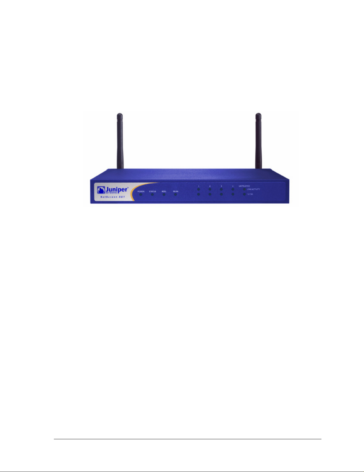
The Juniper Networks NetScreen-5GT Wireless device provides IPSec VPN and firewall
services for a branch office or a retail outlet that uses an integrated wireless 802.11b/g
interface. The NetScreen-5GT Wireless device uses the same firewall, VPN, Antivirus,
Deep Inspection, and traffic management technology as NetScreen’s high-end central site
products.
Juniper Networks offers three models of the NetScreen-5GT Wireless device:
• The Wireless only model.
• The Wireless with Annex A model supports ADSL over standard telephone lines
(POTS).
• The Wireless with Annex B model supports ADSL over Integrated Services
Digital Network (ISDN).
All models support up to four virtual Access Points (APs). Both ADSL models support
ANSI TI.413 Issue 2, ITU G.992.1 (G.dmt), and ITU 992.2 (G.lite) standards.
Each model supports three versions of the device:
• The 10-user version supports up to 10 users.
• The Plus version supports an unrestricted number of users.
• The Extended version provides the same capabilities as the Plus version, with
additional features: High Availability (NSRP Lite), the DMZ security zone, and
additional sessions and tunnel capacity.
ORGANIZATION
This manual has three chapters and one appendix.
Chapter 1, “Connecting the Device” describes how to connect the device to your network,
connect the power, connect an antenna, and install the NetScreen-5GT Wireless device in
a rack.
Chapter 2, “Configuring the Device” describes the default settings and operation of the
NetScreen-5GT Wireless (ADSL) and the configuration required to use the device.
Chapter 3, “Hardware Descriptions” provides an overview of the NetScreen-5GT Wireless
ports, LEDs, and power requirements.
Appendix A, “Specifications” provides a list of physical specifications about the
NetScreen-5GT Wireless device.
NetScreen-5GT Wireless 3
Page 6

Preface
WEBUI CONVENTIONS
Throughout this book, a chevron ( > ) is used to indicate navigation through the WebUI by
selecting menu options and links.
Example: Objects > Addresses > List > New
To access the new address configuration dialog box:
1. Click Objects in the menu column.
The Objects menu option expands to reveal a subset of options for Objects.
2. (Applet menu1) Hover the mouse over Addresses.
(DHTML menu) Click Addresses.
The Addresses option expands to reveal a subset of options for Addresses.
3. Click List.
The address book table appears.
4. Click the New link in the upper right corner.
The new address configuration dialog box appears.
CLI CONVENTIONS
The following conventions are used when presenting the syntax of a command line
interface (CLI) command:
• Anything inside square brackets [ ] is optional.
• Anything inside braces { } is required.
• If there is more than one choice, each choice is separated by a pipe ( | ). For
example,
set interface { ethernet1 | ethernet2 | ethernet3 }
manage
means “set the management options for the ethernet1, ethernet2, or ethernet3
interface”.
• Variables appear in italic. For example:
set admin user name1 password xyz
1. You can choose either the applet or DHTML menu types by clicking the Toggle Menu option at the
bottom of the menu column.
4 User’s Guide
Page 7

When a CLI command appears within the context of a sentence, it is in bold (except for
variables, which are always in italic). For example: “Use the get system command to
display the serial number of a NetScreen device.”
Note: When typing a keyword, you only have to type enough letters to identify the word
uniquely. For example, typing set adm u joe j12fmt54 is enough to enter the command
set admin user joe j12fmt54. Although you can use this shortcut when entering
commands, all the commands documented here are presented in their entirety.
NETSCREEN PUBLICATIONS
To obtain technical documentation for any Juniper Networks NetScreen product, visit
www.juniper.net/techpubs/
For technical support, open a support case using the Case Manager link at http://
www.juniper.net/support/ or call 1-888-314-JTAC (within the United States) or 1-408-745-
9500 (outside the United States).
If you find any errors or omissions in the following content, please contact us at the e-mail
address below:
.
NetScreen Publications
techpubs-comments@juniper.net
NetScreen-5GT Wireless 5
Page 8

Preface
6 User’s Guide
Page 9

Chapter 1
1
Connecting the Device
This chapter describes how to connect the NetScreen-5GT Wireless device to the network,
connect the power, and connect an antenna. If you are using the optional NetScreen-5GT
Wireless rack mount kit, then use the rack mounting instructions that are included at the
end of this chapter.
Note: For safety warnings and instructions, refer to the NetScreen Safety Guide. The
instructions in this guide warn you about situations that could cause bodily injury. Before
working on any equipment, be aware of the hazards involved with electrical circuitry and
be familiar with standard practices for preventing accidents.
CONNECTING THE NETSCREEN DEVICE TO YOUR NETWORKS
The NetScreen device provides firewall and general security for your networks when it is
placed between your internal networks and the Untrusted network. This section describes
the physical connections.
Connecting the Device to an Untrusted Network
Depending upon which model of the NetScreen-5GT Wireless device you have, you can
connect to the Untrusted network in one of the following ways:
• Through an ADSL connection from the ADSL port on the NetScreen device.
• Through an Ethernet connection from the Untrusted port on the NetScreen
device.
Connecting the ADSL Port
Connect the provided ADSL cable from the ADSL port on the NetScreen-5GT Wireless
ADSL device to your telephone outlet. The ADSL port on the Annex A version of the
device uses an RJ-11 connector, while the Annex B version uses an RJ-45 connector. In
the case of Annex B models, the cable you connect fr om the ADSL port to the telephone
outlet is identical in appearance and wiring to a straight-through 10 Base-T Ethernet
cable.
Warning: Make sure that you do not inadvertently connect the Console, Modem, or
Ethernet ports on the NetScreen device to the telephone outlet.
NetScreen-5GT Wireless 7
Page 10
Chapter 1 Connecting the Device
The ADSL line is your primary connection to an outside network. For a backup data link
to an outside network, you can either connect an Ethernet cable from the Untrusted port
on the NetScreen-5GT Wireless ADSL device to an external router, DSL modem, or cable
modem, or connect a serial cable from the Modem port on the device to an external
modem.
Warning: You cannot connect both the Untrusted port and the Modem port on the device
to an outside network at the same time.
Connecting Splitters and Microfilters
A signal splitter divides the telephone signal into low-frequency voice signals for voice
calls and high-frequency data signals for data traffic. Your service provider usually
installs the splitter as part of the equipment that connects your site’s telephone lines to
the provider’s network.
There are also splitters that you may be able to install yourself, depending upon your
service provider equipment. If you are installing such a splitter yourself, then connect the
ADSL cable from the NetScreen device and the telephone line to the appropriate
connectors (for example, “data” or “voice”) on the splitter. You connect the other end of the
splitter to the telephone outlet.
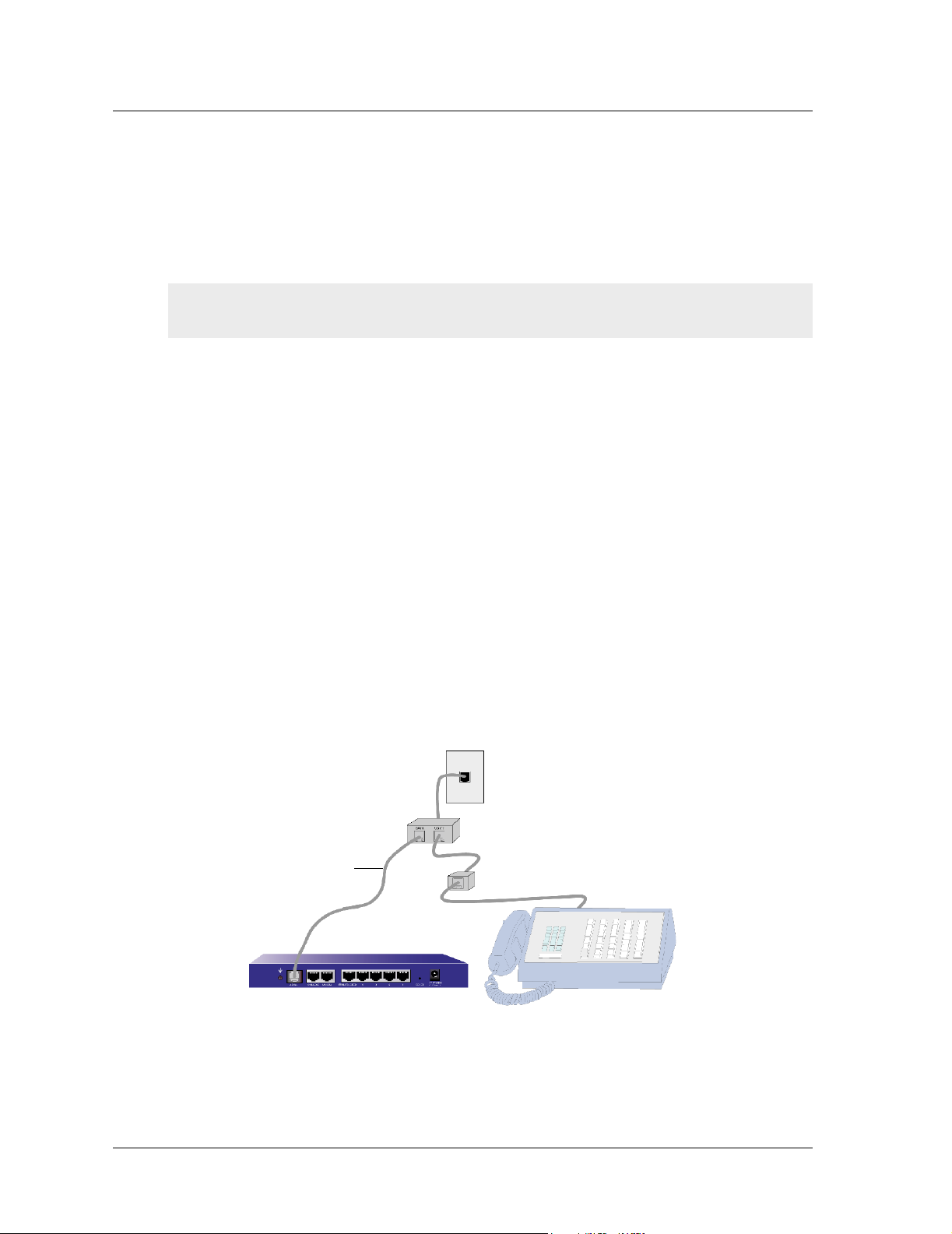
You may need to install a microfilter on each telephone, fax machine, answering machine,
or analog modem that connects to the ADSL line. The microfilter filters out highfrequency noise on the telephone line. You install the microfilter on the telephone line
between the telephone, fax machine, answering machine, or analog modem and the voice
connector on the splitter.
The following shows an example of a microfilter and a splitter that you install on your
site. (You must obtain the appropriate microfilters or splitters from your service provider.)
Telephone Outlet
Splitter
ADSL Cable
Microfilter
8 User’s Guide
Page 11

Connecting the NetScreen Device to Your Networks
Connecting the Untrusted Port
You can establish an internet connection to an external router, DSL modem, or cable
modem, and provide firewall and general security for your network. To establish a highspeed connection, connect the provided Ethernet cable from the Untrusted interface on
the NetScreen-5GT Wireless device to the external router or modem. The NetScreen-5GT
Wireless device autosenses the correct speed, duplex, and polarity settings.
If you are using the NetScreen-5GT Wireless ADSL device, then refer to sections
“Connecting the ADSL Port” on page 7 and “Connecting Splitters and Microfilters” on
page 8 for ADSL connection instructions.
Connecting the Device to Your Internal Network or Workstations
You can connect your LAN or workstation using one or both of the following ways:
• Connecting through one or more of the Trusted Ethernet ports on the NetScreen
device.
• Using a wireless interface on the NetScreen device.
Connecting Trusted Ethernet Ports
The NetScreen-5GT Wireless device contains four Trusted Ethernet ports. You can use
one or more of these ports to connect to LANs via switches or hubs. You can also connect
one or all of the ports directly to workstations, eliminating the need for a hub or switch.
You can use either cross-over or straight-through cables to connect the Ethernet ports to
other devices.
Using the Wireless Interface
If you are using the wireless interface, you need to connect the provided antennae on the
device. If you have the standard 2dB omnidirectional antennae, then screw them onto the
posts marked A and B at the back of the device. Antenna A is located next to the power
cord connection. Bend the antennae at their elbows, making sure not to put pressure on
the bulkhead connector.
If you are using the optional high-gain antenna, then follow the antenna’s connection
instructions.
NetScreen-5GT Wireless 9
Page 12

Chapter 1 Connecting the Device
CONNECTING THE POWER
To connect the power to the NetScreen-5GT Wireless device:
1. Plug the DC connector end of the power cable into the DC power receptacle on
the back of the device.
2. Plug the AC adapter end of the power cable into an AC power source.
Warning: NetScreen recommends using a surge protector for the power connection.
RACK MOUNTING (OPTIONAL)
With a NetScreen-5GT Wireless rack-mount kit, you can mount one or two NetScreen5GT Wireless devices in a standard 19-inch equipment rack. The NetScreen-5GT Wireless
rack-mount kit includes installation instructions and a rack-mounting tray. The
dimensions of the tray are as follows:
Width: 48.26 cm. 19 in.
Height: 4.013 cm. 1-5/8 in. (1 rack unit)
Depth: 33.655 cm. 13-1/4 in.
In addition to the NetScreen-5GT Wireless device(s), rack-mount kit, and equipment rack,
you also need the following:
• Phillips-head screwdriver
• Four screws that match the thread size of the equipment rack
To mount the device in a rack:
1. Use the Phillips-head screwdriver to remove the two screws from the underside
of each NetScreen-5GT Wireless device that you intend to mount. The screws are
located on the underside of the NetScreen-5GT Wireless near the front panel.
(Keep the screws for use in the next step.)
2. Insert the NetScreen-5GT Wireless devices on the rack-mount tray and screw
them to the tray with the screws that you removed in step 1.
10 User’s Guide
Page 13

Rack Mounting (Optional)
3. Screw the left and right tray plates to the equipment rack.
You can run power cords and Ethernet cables through the openings in the floor of the tray
or out the depressions in the back wall. You can also use the space behind the devices to
hold power supplies.
NetScreen-5GT Wireless 11
Page 14

Chapter 1 Connecting the Device
12 User’s Guide
Page 15

Chapter 2
Configuring the Device
This chapter describes how to configure a NetScreen-5GT Wireless device after you have
connected it. If you are accessing the device for the first time using the ScreenOS WebUI
graphical interface, then you can use the Initial Configuration Wizard to guide you
through the basic configuration. To use the Initial Configuration Wizard, refer to the
Juniper Networks NetScreen-5GT Wireless Getting Started Guide.
Topics explained in this chapter include:
• Accessing the Device
• Required Configuration
• Wireless Configuration
• ADSL Configuration
• Optional Configuration
• Verifying External Connectivity
• Resetting the Device to Factory Defaults
Note: After you configure the NetScreen device and verify connectivity to the Internet, you
must register your product at www.juniper.net/support/
services, such as internal antivirus or Deep Inspection Signature Service, can be activated
on the device. After registering your product, use the WebUI to obtain the subscription for
the service. For more information about registering your product and obtaining
subscriptions for specific services, see the “System Parameters” chapter in the
“Fundamentals” volume of the NetScreen Concepts & Examples ScreenOS Reference
Guide for ScreenOS 5.0.0.
2
so that certain ScreenOS
ACCESSING THE DEVICE
This section describes how to access your NetScreen device using the WebUI, Telnet, or a
Console connection.
Using the WebUI
The ScreenOS WebUI is a graphical interface that is available through a web browser. To
use the WebUI, you must be on the same subnetwork as the NetScreen device. To access
the NetScreen-5GT Wireless device with the WebUI management application:
1. Connect your workstation (or your LAN hub) to Trust Ethernet port labeled 1.
2. Make sure that your workstation is on the same subnetwork as the NetScreen
device. If there are no DHCP servers available on the LAN, then the
NetScree-5GT Wireless device acts as a DHCP server. The NetScreen device
provides addresses from 192.168.1.33 to 192.168.1.xx.
NetScreen-5GT Wireless 13
Page 16

Chapter 2 Configuring the Device
3. Launch your browser, enter the default IP address for the Trust interface in the
URL field, and then press Enter. For example, enter the following in the URL
field:
192.168.1.1
The NetScreen WebUI software displays the login prompt.
Note: If you choose to skip the Initial Configuration Wizard, then the WebUI
login prompt automatically appears.
4. If you have not yet changed the default user name and password, then enter
netscreen in both the User Name and Password fields, and then click Login.
(Use lowercase letters only. The User Name and Password fields are both case
sensitive.)
Using Telnet
Telnet is an application that allows you to access devices through an IP network.
Note: You can also access NetScreen devices using Secure Shell (SSH) applications. Refer
to the “Administration” chapter in the “Administration” volume of the NetScreen Concepts
& Examples ScreenOS Reference Guide for ScreenOS 5.0.0 for more information.
To configure the device using Telnet, enter ScreenOS Command Line Interface (CLI)
commands in a Telnet session from your workstation.
1. Connect your workstation (or your LAN hub) to Trust Ethernet port labeled 1.
2. Start a Telnet client application to the default IP address for the Trust interface.
For example, enter the following:
telnet 192.168.1.1
3. If you have not yet changed the default user name and pass word , th en ty pe
netscreen in both the login and password prompts. (Use lowercase letters
only. The login and password fields are both case sensitive.)
14 User’s Guide
Page 17

Required Configuration
Using a Console Connection
The Console port on the NetScreen-5GT Wireless device allows you to access the device
through a serial cable connected to your works tat ion or terminal. To configure the device
using a console connection, enter ScreenOS CLI commands on your terminal or in a
terminal emulation program on your workstation.
Note: For the console connection, use a serial cable with a male RJ-45 connector on one
end and female DB-9 connector on the other end. See Appendix A, Specifications for the
connector pinouts for the serial cable.
To establish a console connection:
1. Plug the female DB-9 end of the serial cable into the serial port of your
computer. (Be sure that the DB-9 connector is seated properly in the port.)
2. Plug the other end of the DB-9 connector into the RJ-45 DB-9 port. (Be sure that
the DB-9 connector is seated properly in the RJ-45 DB-9 port.)
3. Plug the male RJ-45 end of the serial cable into the Console port of the
NetScreen-5GT Wireless device. (Be sure that the RJ-45 connector is seated
properly in the port.)
4. Launch a serial terminal emulation program. (A commonly-used terminal
program is Hilgreave HyperTerminal.) The required settings to launch a console
session with your NetScreen-5GT Wireless device are as follows:
– Baud Rate: 9600
–Parity: No
– Data Bits: 8
–Stop Bit: 1
– Flow Control: None
5. If you have not yet changed the default user name and password, enter
netscreen in both the login and password prompts. (Use lowercase letters
only. The login and password fields are both case sensitive.)
REQUIRED CONFIGURATION
This section describes the configurations that you need to complete to use the NetScreen5GT Wireless devices.
Note: If you have any problems completing a configuration and you need to restore the
device to its default settings, see “Resetting the Device to Factory Defaults” on page 29.
NetScreen-5GT Wireless 15
Page 18

Chapter 2 Configuring the Device
Changing the Admin Name and Password
Because all NetScreen products use the same default admin name and password
(netscreen), it is highly advisable to change your admin name and password
immediately. To change the administrator name and password from “netscreen” and
“netscreen” to “darwin1” and “1240jes”:
WebUI
Configuration > Admin > Administrators > Edit (for the netscreen
Administrator Name): Enter the following, and then click OK:
Administrator Name: darwin1
Old Password: netscreen
Note: Passwords do not display in the WebUI when you type them in.
New Password: 1240jes
Confirm New Password: 1240jes
CLI
set admin name darwin1
set admin password 1240jes
save
For information on creating different levels of administrators, see the “Administration”
chapter in the “Administration” volume of the NetScreen Concepts & Examples ScreenOS
Reference Guide for ScreenOS 5.0.0.
Setting the Date and Time
The time set on the NetScreen device affects events such as the setup of VPN tunnels and
the timing of schedules. The easiest way to set the date and time on the NetScreen device
is to synchronize the system clock on the NetScreen device with the clock on your
computer. To do this in the WebUI:
1. Configuration > Date/Time: Click the Sync Clock with Client button.
A pop-up message prompts you to specify if you have enabled the daylight saving
time option on your computer clock.
2. Click Yes to synchronize the system clock and adjust it according to daylight
saving time or No to synchronize the system clock without adjusting it for
daylight saving time.
You can also use the CLI set clock command in a Telnet or Console session to manually
enter the date and time.
16 User’s Guide
Page 19

WIRELESS CONFIGURATION
This section provides information for configuring the wireless interface on the NetScreen
device. Depending on the type of license you have installed, you can configure up to four
virtual Access Points on a NetScreen-5GT Wireless device. The interface to zone bindings
are static, and there are no wireless interfaces assigned to the Untrust zone. You must
configure at least one wireless interface on the NetScreen device to create a
wireless LAN (WLAN).
Note: If you are operating the NetScreen-5GT Wireless device in a country other than the
United States or Japan, then you must use the set wlan country-code command before a
WLAN connection can be established. This command sets the selectable channel range
and transmit power level.
The figure below shows the default configuration for the NetScreen-5GT Wireless.
To Internet
Wireless Configuration
wireless1 Interface
External router,
switch, or Hub
The default wireless interface has a predefined name “wireless2”. The Trust and wireless2
interfaces are bound to the Trust zone and are configured with the subnetwork addresses
192.168.1.1/24 and 192.168.2.1/24, respectively. This means that all devices that you
connect to in the Trust zone must be in the same subnetwork as either the trust or
wireless2 interface and have IP addresses in one of the two subnetworks. The NetScreen
device is also configured to assign IP addresses for the 192.168.1.1/24 and 192.168.2.1/24
subnetworks to your devices. For more information, refer to “Changing the Trust
Interface Address” on page 29.
(no IP address)
wireless2 Interface
192.168.2.1/24
Trust Interface
192.168.1.1/24
Wzone1 Zone
Hub
Trust Zone
NetScreen-5GT Wireless 17
Page 20

Chapter 2 Configuring the Device
By default, the wireless1 interface is bound to the Wzone1 zone and does not have an IP
address assigned to it. If you want to use the wireless1 interface, then you must configure
an IP address for it. Refer to the NetScreen-5GT Wireless New Features Guide for more
information.
The NetScreen device allows any type of traffic to the Internet that originates from
devices in your Trust zone, but does not allow any traffic that originates in the Internet to
reach your network. You can configure additional restrictions; refer to “Configuring
Additional Policies” on page 25.
Configuring the Wireless Network
Wireless networks consist of names referred to as Service Set Identifiers (SSIDs).
Specifying an SSID allows you to have multiple wireless networks residing in the same
location without interfering with each other. You can have a maximum of eight SSIDs
configured on each device. Once the SSID name is set, you can configure SSID attributes.
To set the SSID name netscreen open, allow wireless network connectivity, and activate
the wireless2 interface:
WebUI
Wireless > SSID > New: Enter the following, and then click OK:
SSID: “netscreen open”
Wireless Interface Binding: wireless2 (select)
Activate Changes > click the Activate Changes button
CLI
set ssid name “netscreen open”
set ssid “netscreen open” authentication open encryption
none
set ssid “netscreen open” interface wireless2
exec wlan reactivate
Once you have set an SSID to the wireless2 interface, you can access the device using the
default wireless2 interface IP address in the steps provided with “Accessing the Device”
on page 13 to configure the device. Refer to the NetScreen-5GT Wireless New Features
Guide for configuration examples, SSID attributes, and CLI commands relating to
wireless security configurations.
Note: You cannot use the wireless2 interface to access the Initial Configuration Wizard
(ICW). The ICW can only be accessed with the physical Trust interface connection.
18 User’s Guide
Page 21

ADSL CONFIGURATION
This section describes the default settings and operation of the NetScreen-5GT Wireless
ADSL Annex A and B devices as they are shipped from the factory. These default settings
are such that, in most cases, there are only a few items that you must configure.
This section describes the following configurations for the Untrust zone interface:
• Configuring the ADSL Interface
• VPI/VCI and Multiplexing Method
• PPPoE or PPPoA
• Annex B Mode
• Configuring a Backup Untrust Zone Interface
• Static IP Address and Netmask
Note: If you have any problems completing a configuration and you need to restore the
device to its default settings, see “Resetting the Device to Factory Defaults” on page 29.
The figure below shows the default configuration for the NetScreen-5GT Wireless ADSL.
ADSL Configuration
To Internet
Telephone
Outlet
ADSL Interface
(adsl1)
The ADSL interface has the predefined name “adsl1” and is the main connection from
your network to the Internet. To allow the NetScreen device (and the devices on your
network) to connect to the Internet, you must configure the adsl1 interface according to
information obtained from your service provider. Refer to “Configuring the ADSL
Interface” on page 20.
wireless1 interface
wireless2 Interface
192.168.2.1/24
Trust Interface
192.168.1.1/24
Wzone1
Hub
Trust Zone
NetScreen-5GT Wireless 19
Page 22

Chapter 2 Configuring the Device
The NetScreen device allows any type of traffic to the Internet that originates from
devices in your Trust zone, but does not allow any traffic that originates in the Internet to
reach your network. You can configure additional restrictions; refer to “Configuring
Additional Policies” on page 25.
Configuring the ADSL Interface
Your network uses the ADSL interface “adsl1” on the NetScreen device to connect to the
service provider’s network through an Asynchronous Transfer Mode (ATM) virtual circuit.
You can configure additional virtual circuits by creating ADSL subinterfaces (see “Adding
Virtual Circuits to an ADSL Interface” on page 20 for more information).
In the WebUI, navigate to the Network > Interfaces page to see a list of the current
interfaces on the NetScreen device. If you are using a Telnet or Console session, enter the
CLI command get interface. You should see that the adsl1 interface is bound to the
Untrust zone. If you used the Initial Configuration Wizard to configure the device, then
there may be an IP address and netmask already assigned to the adsl1 interface.
Note: If you do not want to use the ADSL interface, then you can bind it to the Null zone
with the set interface adsl1 zone null command. If you use the Initial Configuration
Wizard to configure the device, you can choose to not use the ADSL interface as the default
interface to the Untrust zone.
You must configure the adsl1 interface to enable the NetScreen device to connect to the
service provider’s network. To do this, you must obtain the following informa t io n from
your service provider:
• Virtual Path Identifier and Virtual Channel Identifier (VPI/VCI) values
• Asynchronous Transfer Mode (ATM) Adaptation Layer 5 (AAL5) multiplexing
method, which can be one of the following:
– Virtual Circuit (VC)-based multiplexing, in which each protocol is carried
over a separate ATM virtual circuit
– Logical Link Control (LLC) encapsulation, which allows several protocols
to be carried on the same ATM virtual circuit (this is the default
multiplexing method)
• User name and password assigned by the service provider for connection to the
service provider’s network using either the Point-to-Point Protocol over Ethernet
(PPPoE) or Point-to-Point Protocol over ATM (PPPoA)
• Authentication method, if any, provided for the PPPoE or PPPoA connection
• Optionally, a static IP address and netmask value for your network
Adding Virtual Circuits to an ADSL Interface
To add virtual circuits, you create sub-interfaces to the ADSL interface. You can create up
to ten ADSL subinterfaces. For example, to create a new subinterface adsl1.1 that is
bound to the user-defined zone named “Corp1”:
20 User’s Guide
Page 23

ADSL Configuration
WebUI
Network > Interfaces > New ADSL Sub-IF: Enter the following, and then click
Apply:
Interface Name: adsl1.1
VPI/VCI: 0/35
Zone Name: Corp1 (select)
CLI
set interface adsl1.1 pvc 0 35 zone corp1
save
You need to configure an ADSL subinterface in the same way as the main ADSL interface,
including setting the VPI/VCI values, as described in “Configuring the ADSL Interface”
on page 20. You configure an ADSL subinterface independently of the main ADSL
interface, that is, you can configure a different multiplexing method, VPI/VCI, and PPP
client on the subinterface than the main ADSL interface. You can also configure a static
IP address on a subinterface, even if the main ADSL interface does not have a static IP
address. Note that a subinterface and the main ADSL interface can use the same VPI/VCI
values if one interface is configured for PPPoA and the other for PPPoE and they both use
LLC multiplexing.
VPI/VCI and Multiplexing Method
Your service provider assigns a VPI/VCI pair for each virtual circuit connection. For
example, you may receive the VPI/VCI pair 1/1, which means a VPI value of 1 and a VCI
value of 1. These values must match the values that the service provider has configured
on the subscriber’s side of the digital subscriber line access multiplexer (DSLAM).
To configure the VPI/VCI pair 1/1 on the adsl1 interface:
WebUI
Network > Interfaces > Edit (for the adsl1 interface): Enter 1/1 in the VPI/VCI
field, and then click Apply.
CLI
set interface adsl1 pvc 1 1
save
By default, the NetScreen-5GT Wireless ADSL device uses LLC-based multiplexing for
each virtual circuit. To configure the VPI/VCI 1/1 on the adsl1 interface and use LLC
encapsulation on the virtual circuit:
WebUI
Network > Interfaces > Edit (for the adsl1 interface): Enter the following, and
then click Apply:
VPI/VCI: 1 / 2
Multiplexing Method: LLC (selected)
NetScreen-5GT Wireless 21
Page 24

Chapter 2 Configuring the Device
CLI
set interface adsl1 pvc 1 1 mux llc
save
PPPoE or PPPoA
The NetScreen device includes both PPPoE and PPPoA clients to connect to the service
provider’s network over the ADSL link. PPPoE is the most common form of ADSL
encapsulation and is intended for termination on each host on your network. PPPoA is
used primarily for business class service as PPP sessions can be terminated on the
NetScreen device. To allow the NetScreen device to connect to the service provider’s
network, you need to configure the user name and password assigned by the service
provider. The configuration for PPPoA is similar to the configuration for PPPoE.
Note: The NetScreen device supports only one PPPoE session on each virtual circuit.
To configure the user name “roswell” and password “area51” for PPPoE and bind the
PPPoE configuration to the adsl1 interface:
WebUI
Network > PPPoE > New: Enter the following, and then click OK:
PPPoE Instance: poe1
Bound to Interface: adsl1 (select)
Username: roswell
Password: area51
CLI
set pppoe name poe1 username roswell password area51
set pppoe name poe1 interface adsl1
save
There are other PPPoE or PPPoA parameters that you can configure on the NetScreen
device, including method of authentication (by default, the NetScreen device supports
either Challenge Handshake Authentication Protocol or Password Authentication
Protocol), idle timeout (default is 30 minutes), and so on. Ask your service provider if
there are additional PPPoE or PPPoA parameters that you need to configure to enable
proper communications with the service provider’s server.
Annex B Mode
If you connect the Annex B model of the NetScreen-5GT Wireless ADSL device to a
Deutsch Telecom ADSL line, then you must configure the physical interfa ce on the ADSL
port for operation with this equipment. To do this:
22 User’s Guide
Page 25

ADSL Configuration
WebUI
Network > Interfaces > Edit (for the adsl1 interface): Select DT for the Annex B
Mode, and then click Apply.
CLI
set interface adsl1 phy annex-b-mode dt
save
You do not need to configure this setting if you are using the Annex A model of the device
or if you are connecting the device to non-Deutsch Telecom equipment.
Static IP Address and Netmask
If your ISP gave you a specific, fixed IP address and netmask for your network, then
configure the IP address and netmask for the network and the IP address of the router
port connected to the NetScreen device. You need to also specify that the device use the
static IP address. (By default, the NetScreen device acts as a PPPoE or PPPoA client and
receives an IP address for the ADSL interface through negotiations with the PPPoE or
PPPoA server.)
To configure the static IP address 1.1.1.1/24 for the network:
WebUI
Network > Interfaces > Edit (for the adsl1 interface): Enter the following, and
then click Apply:
IP Address/Netmask: 1.1.1.1/24
Static IP: (select)
Note: You need to configure a PPPoE or PPPoA instance and bind it to the adsl1
interface, as described in the previous section. Make sure that you select “Obtain IP
using PPPoE” or “Obtain IP using PPPoA” and the name of the PPPoE or PPPoA
instance.
CLI
set interface adsl1 ip 1.1.1.1/24
set pppoe name poe1 static-ip
save
or
set interface adsl1 ip 1.1.1.1/24
set pppoa name poa1 static-ip
save
NetScreen-5GT Wireless 23
Page 26

Chapter 2 Configuring the Device
To use Domain Name System (DNS) for domain name and address resolution, the
computers in your network need to have the IP address of at least one DNS server. If the
NetScreen device receives an IP address for the ADSL interface through PPPoE or
PPPoA, then it also automatically receives IP addresses for the DNS server(s). If the
computers in your network obtain their IP addresses from the DHCP server on the
NetScreen device, then the computers also obtain these DNS server address(es).
If you assign a static IP address to the ADSL interface, then the service provider must
give you the IP address(es) of the DNS server(s). You can either configure the DNS server
address on each computer in your network or configure the DHCP server on the Trust
zone interface so that it provides the DNS server address to each computer.
To configure the DHCP server on the Trust interface to provide the DNS server address
1.1.1.152 to computers in your network:
WebUI
Network > DHCP > Edit (for the Trust interface) > DHCP Server: Enter
1.1.1.152 for DNS1, and then click Apply.
CLI
set interface trust dhcp server option dns1 1.1.1.152
save
OPTIONAL CONFIGURATION
This section describes the following features on the NetScreen-5GT Wireless devices that
you may want to configure:
• Restricting Management
• Configuring Additional Policies
• Operational Mode
• Changing the Port Mode
• Configuring a Backup Untrust Zone Interface
• Changing the Trust Interface Address
Note: Not all of the optional configurations are described in detail in this manual. Refer
to the appropriate chapters in the NetScreen Concepts & Examples ScreenOS Reference
Guide for ScreenOS 5.0.0 for more information.
24 User’s Guide
Page 27

Optional Configuration
Restricting Management
By default, anyone in your network can manage the NetScreen device if they know the
login and password. You can configure the NetScreen device to be managed only from one
or more specific hosts on your network. (And you can choose which services — for
example, WebUI, Telnet, ping — you want enabled on the NetScreen device.) Refer to the
“Administration” chapter in the “Administration” volume of the NetScreen Concepts &
Examples ScreenOS Reference Guide for ScreenOS 5.0.0.
Configuring Additional Policies
The NetScreen-5GT Wireless devices are configured with a default policy that permits
workstations in the Trust zone of your network to access any kind of service with outside
computers, while outside computers are not allowed to access or start sessions with your
workstations. You can configure policies that direct the NetScreen device to permit
outside computers to start specific kinds of sessions with your computers. To create or
modify policies, refer to the “Policies” chapter in the “Fundamentals” volume of the
NetScreen Concepts & Examples ScreenOS Reference Guide for ScreenOS 5.0.0.
Operational Mode
The operational mode is the way an interface on a NetScreen device processes traffic
between zones. By default, the NetScreen-5GT Wireless devices operates in Route mode
with network address translation (NAT) enabled on the Trust interface. This means that
when devices in the Trust zone send traffic to the Internet, the NetScreen device replaces
the original source IP addresses with the IP address of the Untrust interface. While the
NetScreen device assigns “private” IP addresses to the devices in your network, these
addresses remain hidden to computers outside your network.
If all devices in your network have public IP addresses, then you can configure the
NetScreen device for Route mode without NAT enabled. In Route mode without NAT
enabled, the NetScreen device routes traffic by checking IP addresses. For more
information about configuring the device for Route mode without NAT enabled, refer to
the “Interface Modes” chapter in the “Fundamentals” volume of the NetScreen Concepts &
Examples ScreenOS Reference Guide for ScreenOS 5.0.0.
NetScreen-5GT Wireless 25
Page 28

Chapter 2 Configuring the Device
Changing the Port Mode
The port mode is the binding of physical ports, logical interfaces, and zones.
Warning: Changing the port mode removes any existing configurations on the NetScreen
device. Therefore, change the port mode before configuring the device.
The following table summarizes the port, interface, and zone bindings provided by the
port modes that are available on the NetScreen-5GT Wireless devices:
Trust-Untrust Port Mode
Port Name
1 trust Trust ethernet1 Work ethernet1 Trust
2 trust Trust ethernet1 Work ethernet1 Trust
3 trust Trust ethernet2 Home ethernet2 DMZ
4 trust Trust ethernet2 Home ethernet2 DMZ
Untrusted untrust Null
Modem serial Null
ADSL
a
Interface Zone Interface Zone Interface Zone
d
adsl1 Untrust or
V1-Untrust
b
Home-Work Port Mode Trust/Untrust/DMZ
(Extended) Mode
c
c
ethernet4 Null
serial Null
c
c
ethernet4 Null
serial Null
c
c
adsl1 Untrust adsl1 Untrust
wireless1 Wzone1 wireless1 Wzone1 wireless1 Wzone1
wireless2 Trust or
wireless2 Work wireless2 Trust
V1-Trust
wireless3 Home wireless3 DMZ
wireless4 Wzone2
a. As labeled on the NetScreen appliance chassis.
b. Default port mode.
c. You can configure a backup interface to the Untrust zone, using either the Untrusted Ethernet port or the
Modem port. See “Configuring a Backup Untrust Zone Interface” on page 28.
d. Only available on the ADSL Annex A and B devices.
Dual Untrustb Port Mode Combinedc Port Mode
Port Name
a
Interface Zone Interface Zone
1 ethernet1 Trust ethernet1 Work
2 ethernet1 Trust ethernet2 Home
3 ethernet1 Trust ethernet2 Home
4 ethernet2 Untrust ethernet3 Untrust
Untrusted ethernet3 Untrust ethernet4 Untrust
26 User’s Guide
Page 29

Dual Untrustb Port Mode Combinedc Port Mode
Port Name
Modem serial Null
ADSL
a
Interface Zone Interface Zone
d
adsl1 Untrust or
V1-Untrust
wireless1 Wzone1 wireless1 Wzone1
Optional Configuration
c
serial Null
adsl1 Untrust
c
wireless2 Trust or
V1-Trust
a. As labeled on the NetScreen appliance chassis.
wireless2 Work
wireless3 Home
b. Only available on the Wireless only device.
c.
Only available on the Wireless only device.
d. Only available on the Wireless ADSL Annex A and B devices.
To change the NetScreen device to the Home-Work port mode:
WebUI
Configuration > Port Mode: Select Home-Work from the drop-down list, and
then click Apply.
At the following prompt, click OK:
Operational mode change will erase current configuration and reset the device,
continue?
CLI
exec port-mode home-work
At the following prompt, enter y (for yes):
Change port mode from <trust-untrust> to <home-work> will
erase system configuration and reboot box
Are you sure y/[n]? y
NetScreen-5GT Wireless 27
Page 30

Chapter 2 Configuring the Device
Configuring a Backup Untrust Zone Interface
By default, on NetScreen-5GT Wireless ADSL device, the adsl1 interface is the primary
connection to an outside network. Each port mode available on the NetScreen-5GT
Wireless ADSL device allows you the option of connecting either the Untrusted Ethernet
port or the Modem port as a backup connection to the outside network (see “Changing the
Port Mode” on page 26). You must bind the backup interface to the Untrust zone and
configure the interface appropriately.
Note: You can configure only one backup interface, using either the Untrusted Ethernet
port or Modem port connection. If you use the Untrusted port for the backup connection,
then configure the Untrust interface in Trust-Untrust port mode or the ethernet3 interface
for other port modes. If you use the Modem port for the backup connection, then configure
the serial interface for all port modes.
For example, to bind the Untrust interface to the Untrust zone:
WebUI
Network > Interfaces > Edit (for the untrust interface): Select Untrust from the
Zone Name drop-down list, and then click OK.
CLI
set interface untrust zone untrust
save
You also need to set a static IP address for the Untrust interface, or specify whether the
IP address for the interface is obtained via either DHCP or PPPoE. See the “Interfaces”
chapter in the “Fundamentals” volume of the NetScreen Concepts & Examples ScreenOS
Reference Guide for ScreenOS 5.0.0 for more information about configuring interface
parameters.
When the adsl1 interface and either the Ethernet interface (named untrust or ethernet3,
depending upon the port mode) or the serial interface is bound to the Untrust zone,
interface failover is automatically configured. That is, if the adsl1 interface becomes
unavailable, the NetScreen device automatically sends traffic to the ba ckup interface. The
device automatically sends traffic to the adsl1 interface when the adsl1 interface is again
available.
Note: Only the adsl1 interface is affected by failover. That is, if you have also configured
ADSL subinterfaces, the subinterfaces do not fail over to the backup interface.
You can also manually force failover and failback on the adsl1 interface. For more
information, see the “Interface Redundancy” chapter in the “High Availability” volume of
the NetScreen Concepts & Examples ScreenOS Reference Guide for ScreenOS 5.0.0.
28 User’s Guide
Page 31

Verifying External Connectivity
Changing the Trust Interface Address
You can change the IP address and netmask of the Trust and wireless interfaces if
necessary. (Remember that when the Trust interface is in NAT mode, the IP addresses of
devices in your network are never seen by computers outside your network; outside
computers see only the IP address of the Untrust interface.) For example, you might need
to change the Trust interface to match the IP addresses that already exist on your
network. If you change the IP address and netmask of the Trust interface, then you also
need to change either the range of addresses that the NetScreen device assigns via DHCP
to devices in the network or disable the DHCP server on the Trust interface.
If the computers in your network obtain their IP addresses from the DHCP server on the
NetScreen device, then the computers also obtain their default gateway from the
NetScreen device. If a computer has a statically assigned IP address, then you must
manually set its default gateway to the IP address of the Trust interface on the NetScreen
device.
To assign a different IP address and netmask to the Trust interface, refer to the
“Interfaces” chapter in the “Fundamentals” volume of the NetScreen Concepts & Examples
ScreenOS Reference Guide for ScreenOS 5.0.0.
To change the DHCP settings for the NetScreen device, refer to the “System Parameters”
chapter in the “Fundamentals” volume of the NetScreen Concepts & Examples ScreenOS
Reference Guide for ScreenOS 5.0.0.
VERIFYING EXTERNAL CONNECTIVITY
To verify that workstations in your network can access resources on the Internet, start a
Web browser from any workstation in the network and enter the following URL:
www.juniper.net
.
RESETTING THE DEVICE TO FACTORY DEFAULTS
If you lose the admin password, you can reset the NetScreen device to its default settings.
This destroys any existing configurations, but restores access to the device.
Warning: Resetting the device deletes all existing configuration settings and renders
existing firewall and VPN service inoperative.
You can restore the device to its default settings in one of the following ways:
• Using a Console connection. For further information, see the “Administration”
chapter in the “Administration” volume of the NetScreen Concepts & Examples
ScreenOS Reference Guide for ScreenOS 5.0.0.
• Using the reset pinhole on the rear panel of the devi ce, as des crib ed in the ne xt
section.
NetScreen-5GT Wireless 29
Page 32

Chapter 2 Configuring the Device
Using the Reset Pinhole
You can reset the device and restore the factory default settings by pressing the reset
pinhole. To perform this operation, you need t o either view the device status LEDs on the
front panel or have a Console session as described in “Using a Console Connection” on
page 15.
1. Locate the reset pinhole on the rear panel. Using a thin, firm wire (such as a
paper clip), push the pinhole for four to six seconds and then release.
The Status LED blinks amber. A message on the Console states that erasure of
the configuration has started and the system sends an SNMP/SYSLOG alert.
2. Wait for one to two seconds.
Reset Pinhole
After the first reset, the Status LED blinks green; the device is now waiting for
the second reset. The Console message now states that the device is waiting for a
second confirmation.
3. Push the reset pinhole again for four to six seconds.
The Console message verifies the second confirmation. The Status LED lights
amber for one-half second and then returns to the blinking green state.
The device then resets to its original factory settings. When the device resets,
the Status LED turns amber for one-half second and then glows green. The
Console displays device bootup messages. The system generates SNMP and
SYSLOG alerts to configured SYSLOG or SNMP trap hosts.
After the device has rebooted, the Console displays the login prompt for the
device. The status LED now blinks green.
If you do not follow the complete sequence, the reset process cancels without any
configuration change and the console message states that the erasure of the configuration
is aborted. The Status LED returns to blinking green. If the device did not reset, an
SNMP alert is sent to confirm the failure.
30 User’s Guide
Page 33

Chapter 3
Hardware Descriptions
This chapter provides detailed descriptions of the NetScreen-5GT Wireless chassis.
PORT AND POWER CONNECTORS
The rear panel of the NetScreen-5GT Wireless device contains port and power connectors.
Antenna B Antenna A
3
NetScreen-5GT Wireless 31
Page 34

Chapter 3 Hardware Descriptions
The DC power receptacle is for connecting power to the NetScreen-5GT Wireless. The
Reset pinhole allows you to reset the device and restore its factory default settings. The
NetScreen-5GT Wireless device includes the following ports:
Port Description Connector Speed/Protocol
ADSL When applicable, enables an Internet
connection through an ADSL data link.
Console Enables a serial connection with the system.
Used for launching Command Line Interface
(CLI) sessions.
Modem Enables a dial backup serial Internet
connection through an external modem.
Untrusted Enables a primary or backup Internet or
untrusted network connection through an
external router, DSL modem, or cable modem.
Ports 1-4 Enables direct connections to workstations or
a LAN connection through a switch or hub.
This connection also allows you to manage
the device through a Telnet session or the
WebUI management application.
Antenna A
& B
Enables direct connection to workstations in
vicinity of a wireless radio connection.
This connection allows you to manage the
device through a Telnet session or the WebUI
management application.
RJ-11 (Annex A)
RJ-45 (Annex B)
RJ-45 9600 bps/
RJ-45 9600 bps-115 Kbps/
RJ-45 10/100 Mbps/
RJ-45 10/100 Mbps/
RPSMA 802.11b
ANSI T1.413 Issue 2
ITU G.992.1 (G.dmt)
ITU 992.2 (G.lite)
RS-232
RS-232
Ethernet
Autosensing duplex
and polarity
Ethernet
Autosensing duplex
and polarity
802.11g
Warning: Do not connect a phone line or ISDN line directly to the Modem port on the
NetScreen-5GT Wireless device. You must first connect the device to a modem, using an
RS-232 port, and then connect the modem to the line.
STATUS LEDS
The front panel of the NetScreen-5GT Wireless device has power and status LEDs for the
device and port status LEDs for the interfaces.
32 User’s Guide
Page 35

Status LEDs
Main Status LEDs for the Device
The device status LEDs indicate whether the device is operating properly. The following
table describes the status for each LED.
LED Status Meaning
POWER green Indicates the system is receiving power.
off Indicates the system is not receiving power.
STATUS blinking
green
green Indicates the system is starting up.
red Indicates a diagnostics or system initialization error.
off Indicates the system is not operational.
ADSL
(on the
Wireless ADSL
only)
WLAN slow blinking
green Indicates the ADSL loop is up.
off Indicates the ADSL loop is down.
green
fast blinking
green
Indicates the system is functioning.
Indicates that a Wireless connection is established, but there is no
link activity.
Indicates that a Wireless connection is established. The blink rate is
proportional to the link activity.
off Indicates there is no Wireless connection established.
Port Status LEDs
The port status LEDs indicate whether the ports on the device are operating properly.
The following table describes the possible status for the ports.
LED LED Color Meaning of the LED
Link/Activity blinking green Indicates the device detects Ethernet traffic for the port.
off Indicates the port has not established a link with another device.
green Indicates the port has established a link with another device.
10/100 green Indicates the port is connected to a 100 Base-T device.
off Indicates the port is connected to a 10 Base-T device.
NetScreen-5GT Wireless 33
Page 36

Chapter 3 Hardware Descriptions
34 User’s Guide
Page 37

Appendix A
Specifications
This appendix provides general system specifications for the NetScreen- 5GT Wireless
device.
Attributes
Height 2.93 centimeters 1.15 inches
Depth 18.45 centimeters 7.26 inches
Width 20.8 centimeters 8.19 inches
Weight .9 kilograms 1.98 pounds
Electrical
Switching Regulator AC voltage: 100-240 VAC
+/- 10% 50/60 Hz
AC Watts: 12 Watts
DC voltage: 12 Volts
Environmental
Normal altitude 0°-40° C, 32-105°F
A
Relative humidity 10-90%
Non-condensing 10-90%
The maximum normal altitude is 3,657.6 meters (12,000 feet)
Certifications
Safety UL, CUL, CE, CB, A-Tick
EMI FCC Part 15 class B, VCCI
Ethernet Connectors
Standard 100Base-TX
Media Type Category 5 and higher
Unshielded Twisted Pair (UTP) Cable
Maximum Distance 100 meters (328.08 feet)
The RJ-45 twisted-pair ports are compatible with the IEEE 802.3 Type 10/100 Base-T standard
ADSL Connector
Types 6-pin RJ-11 connector for Annex A
RJ-45 connector for Annex B
Media Type Standard telephone cable
NetScreen-5GT Wireless 35
Page 38

Appendix A Specifications
CONSOLE AND MODEM ADAPTER CONNECTIONS
The following table lists the RJ-45 connector definitions. To employ a standard UART
port, both the console and the modem ports use this configuration.
RJ-45 Signal Abbreviation DCE
1 Request To Send RTS In
2 Data Terminal Ready DTR In
3 Transmitted Data TD In
4, 5 Signal Ground SGND N/A
6 Received Data RD Out
7 Not Connected
8 Clear To Send CTS Out
The table below lists the RJ-45 to DB-9 adapter connection definitions. To employ a
standard UART port, both the console and the modem ports must use this configuration
.
DB9 Signal Abbreviation DTE DCE RJ45
1 Data Carrier Detect DCD In Out NC
2 Received Data RD In Out 3
3 Transmitted Data TD Out In 6
4 Data Terminal Ready DTR Out In 7
5 Signal Ground SGND N/A N/A 4
6 Data Set Ready DSR In Out 2
7 Request To Send RTS Out In 8
8 Clear To Send CTS In Out 1
9 Ring Indicator RI In Out NC
Note: If you use the Console cable that is provided with the NetScreen device to connect to
a modem, then you need to obtain and install a null modem adapter on the modem
connector.
36 User’s Guide
Page 39

A
AAL5 multiplexing 20
adding virtual circuit 20
address of Trust zone interface 29
admin name, changing 16
ADSL
configuring interface 20
connecting the cable 7
connecting the port 7
Annex A 7
Annex B 7
configuring for Deutsch Telecom 22
ATM Adaptation Layer 5 20
B
backup interface to Untrust zone 28
C
changing login name and password 16
changing the port mode 26
configuration
default settings 19
optional 24
required 15, 19
connecting power 10
connectors 31
Console, using 15
conventions
WebUI 4
D
date, setting 16
default settings 19
restoring 29
Deutsch Telecom, configuring Annex B 22
G
Guide Organization 3
LLC encapsulation 20
Logical Link Control encapsulation 20
M
managing device from specific host 25
microfilter 8
mounting device in rack 10
multiplexing
configuring 21
N
NetScreen Publications 5
P
password
changing 16
Point-to-Point Protocol over ATM
See PPPoA
Point-to-Point Protocol over Ethernet
See PPPoE
policies, configuring additional 25
port connectors 31
port mode, changing 26
port status LEDs 33
power connectors 31
power, connecting 10
PPPoA 20
configuring 22
PPPoE 20
configuring 22
R
rack mounting the device 10
registering the device 13
reset device to default settings 29
reset pinhole, using 30
restoring default settings 29
restricting management from specific host 25
Route mode 25
L
LEDs
port status 33
Status 32
NetScreen-5GT Wireless IX-37
S
setting device clock 16
signal splitter 8
splitter, signal 8
Page 40

static IP address 20
configuring 23
status LEDs 32
T
Telnet, using 14
time, setting 16
Transparent mode 25
Trust zone
configuring interface address 29
U
Untrust zone, configuring backup interface 28
V
VC multiplexing 20
verifying connectivity 29
Virtual Channel multiplexing 20
virtual circuit, adding 20
Virtual Path Identifier/Virtual Channel Identifier
See VPI/VCI
VPI/VCI 20
configuring 21
W
WebUI, conventions 4
WebUI, using 13
IX-38 User’s Guide
 Loading...