

Page 1

MX480 3D Universal Edge Router
Hardware Guide
Published: 2013-02-04
Copyright © 2013, Juniper Networks, Inc.
Page 2

Juniper Networks, Inc.
1194 North Mathilda Avenue
Sunnyvale, California 94089
USA
408-745-2000
www.juniper.net
This productincludes the Envoy SNMP Engine, developed by Epilogue Technology, anIntegrated Systems Company. Copyright © 1986-1997,
Epilogue Technology Corporation. All rights reserved. This program and its documentation were developed at private expense, and no part
of them is in the public domain.
This product includes memory allocation software developed by Mark Moraes, copyright © 1988, 1989, 1993, University of Toronto.
This product includes FreeBSD software developed by the University of California, Berkeley, and its contributors. All of the documentation
and software included in the 4.4BSD and 4.4BSD-Lite Releases is copyrighted by the Regents of the University of California. Copyright ©
1979, 1980, 1983, 1986, 1988, 1989, 1991, 1992, 1993, 1994. The Regents of the University of California. All rights reserved.
GateD software copyright © 1995, the Regents of the University. All rights reserved. Gate Daemon was originated and developed through
release 3.0 by Cornell University and its collaborators. Gated is based on Kirton’s EGP, UC Berkeley’s routing daemon (routed), and DCN’s
HELLO routing protocol. Development of Gated has been supported in part by the National Science Foundation. Portions of the GateD
software copyright © 1988, Regents of the University of California. All rights reserved. Portions of the GateD software copyright © 1991, D.
L. S. Associates.
This product includes software developed by Maker Communications, Inc., copyright © 1996, 1997, Maker Communications, Inc.
Juniper Networks, Junos, Steel-Belted Radius, NetScreen, and ScreenOS are registered trademarks of Juniper Networks, Inc. in the United
States and other countries. The Juniper Networks Logo, the Junos logo, and JunosE are trademarks of Juniper Networks, Inc. All other
trademarks, service marks, registered trademarks, or registered service marks are the property of their respective owners.
Juniper Networks assumes no responsibility for any inaccuracies in this document. Juniper Networks reserves the right to change, modify,
transfer, or otherwise revise this publication without notice.
Products made or sold by Juniper Networks or components thereof might be covered by one or more of the following patents that are
owned by or licensed to Juniper Networks: U.S. Patent Nos. 5,473,599, 5,905,725, 5,909,440, 6,192,051, 6,333,650, 6,359,479, 6,406,312,
6,429,706, 6,459,579, 6,493,347, 6,538,518, 6,538,899, 6,552,918, 6,567,902, 6,578,186, and 6,590,785.
MX480 3D Universal Edge Router Hardware Guide
Copyright © 2013, Juniper Networks, Inc.
All rights reserved.
Revision History
January 2013—Added support for Application Services ModularLine Card (AS MLC), and components ApplicationServices ModularStorage
Card (AS MSC) and Application Services Modular Processing Card (AS MXC).
September 2011—Added the upgrade procedure for the Enhanced MX SCB and information for the new SCB
July 2011—Updated AC and DC power specification topics.
April 2011—Added high-capacity power supply installation information.
March 2011—Updated Routing Engine content.
December 2010—Added RE-S-1800 content.
August 2010—Updated site electrical guidelines.
April 2010—Added installation and removal instructions for dual-wide MICs.
January 2010—Added information about Modular Port Concentrators (MPCs) and Modular Interface Cards (MICs).
July 2009—Updated product names. Updated information about securing power lugs.
10 April 2009—530-020794-01. Revision 6. Added information about the MX Series FPC2. Added warning about removing transceivers.
6 February 2009—530-020794-01. Revision 5. Added information about MX Series FPCs and PICs. Revised sections into modular topics
for easier customer access.
30 August 2008—530-020794-01. Revision 4. Corrected the specifications of the shipping crate, AUX/CONSOLE ports, and AC power
cords. Updated the number of Packet Forwarding Engines. Added a physical specifications appendix. Updated the location of the SCBs
and how to operate the SCB ejector handles. Removed DPC faceplate LED information.
15 May 2008—530-020794-01. Revision 3. Corrected the procedures to replace AC power cords and DC power cables, and to install the
router without a lift. Updatedthe AC andpower requirements andspecifications, host subsystem OFFLINE LED description, chassisgrounding
points description, and clearance requirements. Added recommendation to replace the air filter every 6 months.
19 October 2007—530-020794-01. Revision 2.Added cablemanagement brackets installation procedure. Fixed unresolvedcross-references.
Copyright © 2013, Juniper Networks, Inc.ii
Page 3

19 September 2007—530-020794-01. Revision 1. Initial release.
The information in this document is current as of the date on the title page.
YEAR 2000 NOTICE
Juniper Networks hardware and software products are Year 2000 compliant. Junos OS has no known time-related limitations through the
year 2038. However, the NTP application is known to have some difficulty in the year 2036.
END USER LICENSE AGREEMENT
The Juniper Networks product that is the subject of this technical documentation consists of (or is intended for use with) Juniper Networks
software. Use of such software is subject to the terms and conditions of the End User License Agreement (“EULA”) posted at
http://www.juniper.net/support/eula.html. By downloading, installing or using such software, you agree to the terms and conditions
of that EULA.
iiiCopyright © 2013, Juniper Networks, Inc.
Page 4

Copyright © 2013, Juniper Networks, Inc.iv
Page 5

Table of Contents
About the Documentation . . . . . . . . . . . . . . . . . . . . . . . . . . . . . . . . . . . . . . . . . xxi
Junos Documentation and Release Notes . . . . . . . . . . . . . . . . . . . . . . . . . . . . xxi
Documentation Conventions . . . . . . . . . . . . . . . . . . . . . . . . . . . . . . . . . . . . . . xxi
Documentation Feedback . . . . . . . . . . . . . . . . . . . . . . . . . . . . . . . . . . . . . . . xxiii
Requesting Technical Support . . . . . . . . . . . . . . . . . . . . . . . . . . . . . . . . . . . . xxiii
Self-Help Online Tools and Resources . . . . . . . . . . . . . . . . . . . . . . . . . . xxiii
Opening a Case with JTAC . . . . . . . . . . . . . . . . . . . . . . . . . . . . . . . . . . . . xxiv
Part 1 MX480 3D Universal Edge Router Overview
Chapter 1 MX480 Router Overview . . . . . . . . . . . . . . . . . . . . . . . . . . . . . . . . . . . . . . . . . . . . 3
MX480 Router Description . . . . . . . . . . . . . . . . . . . . . . . . . . . . . . . . . . . . . . . . . . . . 3
MX480 Component Redundancy . . . . . . . . . . . . . . . . . . . . . . . . . . . . . . . . . . . . . . . 4
Chapter 2 MX480 Hardware Components . . . . . . . . . . . . . . . . . . . . . . . . . . . . . . . . . . . . . . 7
MX480 Chassis Description . . . . . . . . . . . . . . . . . . . . . . . . . . . . . . . . . . . . . . . . . . . . 7
MX480 Midplane Description . . . . . . . . . . . . . . . . . . . . . . . . . . . . . . . . . . . . . . . . . . 9
MX480 Dense Port Concentrator (DPC) Overview . . . . . . . . . . . . . . . . . . . . . . . . . 10
MX480 Dense Port Concentrator (DPC) Description . . . . . . . . . . . . . . . . . . . 10
DPC Components . . . . . . . . . . . . . . . . . . . . . . . . . . . . . . . . . . . . . . . . . . . . 12
MX480 Dense Port Concentrator (DPC) LEDs . . . . . . . . . . . . . . . . . . . . . . . . . 12
MX480 Modular Port Concentrator (MPC) Overview . . . . . . . . . . . . . . . . . . . . . . . 13
MX480 Modular Port Concentrator (MPC) Description . . . . . . . . . . . . . . . . . . 13
MPC Components . . . . . . . . . . . . . . . . . . . . . . . . . . . . . . . . . . . . . . . . . . . 14
MX480 Modular Port Concentrator (MPC) LEDs . . . . . . . . . . . . . . . . . . . . . . . 15
MX480 Modular Interface Card (MIC) Overview . . . . . . . . . . . . . . . . . . . . . . . . . . . 15
MX480 Modular Interface Card (MIC) Description . . . . . . . . . . . . . . . . . . . . . 15
MX480 Modular Interface Card (MIC) LEDs . . . . . . . . . . . . . . . . . . . . . . . . . . 16
MX480 Flexible PIC Concentrator (FPC) Overview . . . . . . . . . . . . . . . . . . . . . . . . 16
MX480 Flexible PIC Concentrator (FPC) Description . . . . . . . . . . . . . . . . . . . 16
FPC Components . . . . . . . . . . . . . . . . . . . . . . . . . . . . . . . . . . . . . . . . . . . . 18
MX480 Flexible PIC Concentrator (FPC) LEDs . . . . . . . . . . . . . . . . . . . . . . . . 18
FPCs Supported by the MX480 Router . . . . . . . . . . . . . . . . . . . . . . . . . . . . . . 19
MX480 PIC Overview . . . . . . . . . . . . . . . . . . . . . . . . . . . . . . . . . . . . . . . . . . . . . . . . 19
MX480 PIC Description . . . . . . . . . . . . . . . . . . . . . . . . . . . . . . . . . . . . . . . . . . . 19
MX480 PIC LEDs . . . . . . . . . . . . . . . . . . . . . . . . . . . . . . . . . . . . . . . . . . . . . . . 20
MX480 Application Services Modular Line Card (AS MLC) Overview . . . . . . . . . . 20
MX480 Application Services Modular Line Card Description . . . . . . . . . . . . . 20
MX480 AS MLC Function . . . . . . . . . . . . . . . . . . . . . . . . . . . . . . . . . . . . . . 21
AS MLC Components . . . . . . . . . . . . . . . . . . . . . . . . . . . . . . . . . . . . . . . . . 21
vCopyright © 2013, Juniper Networks, Inc.
Page 6

MX480 3D Universal Edge Router Hardware Guide
MX480 SCB, Power Supply, and Cooling System Requirements for AS
MX480 Application Services Modular Storage Card Overview . . . . . . . . . . . . . . . 23
MX480 Application Services Modular Storage Card Description . . . . . . . . . . 23
MX480 AS MSC LEDs . . . . . . . . . . . . . . . . . . . . . . . . . . . . . . . . . . . . . . . . . . . . 24
MX480 Application Services Modular Processing Card Overview . . . . . . . . . . . . . 24
MX480 Application Services Modular Processing Card Description . . . . . . . 24
MX480 AS MXC LEDs . . . . . . . . . . . . . . . . . . . . . . . . . . . . . . . . . . . . . . . . . . . . 25
MX480 Host Subsystem Overview . . . . . . . . . . . . . . . . . . . . . . . . . . . . . . . . . . . . . 25
MX480 Host Subsystem Description . . . . . . . . . . . . . . . . . . . . . . . . . . . . . . . . 26
MX480 Host Subsystem LEDs . . . . . . . . . . . . . . . . . . . . . . . . . . . . . . . . . . . . . 26
MX480 Switch Control Board (SCB) Overview . . . . . . . . . . . . . . . . . . . . . . . . . . . 26
MX480 Switch Control Board (SCB) Description . . . . . . . . . . . . . . . . . . . . . . 26
SCB Slots . . . . . . . . . . . . . . . . . . . . . . . . . . . . . . . . . . . . . . . . . . . . . . . . . . 27
SCB Redundancy . . . . . . . . . . . . . . . . . . . . . . . . . . . . . . . . . . . . . . . . . . . . 27
SCB Components . . . . . . . . . . . . . . . . . . . . . . . . . . . . . . . . . . . . . . . . . . . . 27
MX480 Switch Control Board (SCB) LEDs . . . . . . . . . . . . . . . . . . . . . . . . . . . 28
MX480 Enhanced Switch Control Board Description . . . . . . . . . . . . . . . . . . . 29
MX SCBE Slots . . . . . . . . . . . . . . . . . . . . . . . . . . . . . . . . . . . . . . . . . . . . . . 30
MX SCBE Redundancy . . . . . . . . . . . . . . . . . . . . . . . . . . . . . . . . . . . . . . . 30
MX SCBE Components . . . . . . . . . . . . . . . . . . . . . . . . . . . . . . . . . . . . . . . 30
MX480 Enhanced Switch Control Board LEDs . . . . . . . . . . . . . . . . . . . . . . . . 30
MX480 Routing Engine Overview . . . . . . . . . . . . . . . . . . . . . . . . . . . . . . . . . . . . . . 32
MX480 Routing Engine Description . . . . . . . . . . . . . . . . . . . . . . . . . . . . . . . . . 32
Routing Engine Components . . . . . . . . . . . . . . . . . . . . . . . . . . . . . . . . . . . 32
Routing Engine Interface Ports . . . . . . . . . . . . . . . . . . . . . . . . . . . . . . . . . 33
Routing Engine Boot Sequence . . . . . . . . . . . . . . . . . . . . . . . . . . . . . . . . . 33
RE-S-1800 Routing Engine Description for MX Series . . . . . . . . . . . . . . . . . . 34
RE-S-1800 Routing Engine Components . . . . . . . . . . . . . . . . . . . . . . . . . 34
RE-S-1800 Routing Engine Boot Sequence . . . . . . . . . . . . . . . . . . . . . . . 35
RE-S-1800 Routing Engine LEDs . . . . . . . . . . . . . . . . . . . . . . . . . . . . . . . . . . . 35
MX480 Routing Engine LEDs . . . . . . . . . . . . . . . . . . . . . . . . . . . . . . . . . . . . . . 36
MX480 Craft Interface Overview . . . . . . . . . . . . . . . . . . . . . . . . . . . . . . . . . . . . . . . 36
MX480 Craft Interface Description . . . . . . . . . . . . . . . . . . . . . . . . . . . . . . . . . . 37
Alarm LEDs and Alarm Cutoff/Lamp Test Button on the MX480 Craft
Interface . . . . . . . . . . . . . . . . . . . . . . . . . . . . . . . . . . . . . . . . . . . . . . . . . . . 37
MX480 Component LEDs on the Craft Interface . . . . . . . . . . . . . . . . . . . . . . 38
Host Subsystem LEDs on the MX480 Craft Interface . . . . . . . . . . . . . . . 38
Power Supply LEDs on the MX480 Craft Interface . . . . . . . . . . . . . . . . . 39
DPC and MPC LEDs on the MX480 Craft Interface . . . . . . . . . . . . . . . . . 39
FPC LEDs on the MX480 Craft Interface . . . . . . . . . . . . . . . . . . . . . . . . . 39
SCB LEDs on the MX480 Craft Interface . . . . . . . . . . . . . . . . . . . . . . . . . 40
Fan LEDs on the MX480 Craft Interface . . . . . . . . . . . . . . . . . . . . . . . . . . 40
Alarm Relay Contacts on the MX480 Craft Interface . . . . . . . . . . . . . . . . . . . 40
MX480 Power Supply Overview . . . . . . . . . . . . . . . . . . . . . . . . . . . . . . . . . . . . . . . 41
MX480 Power System Description . . . . . . . . . . . . . . . . . . . . . . . . . . . . . . . . . . 41
MX480 AC Power Supply Description . . . . . . . . . . . . . . . . . . . . . . . . . . . . . . . 42
AC Power Supply Configurations . . . . . . . . . . . . . . . . . . . . . . . . . . . . . . . 43
MX480 AC Power Supply LEDs . . . . . . . . . . . . . . . . . . . . . . . . . . . . . . . . . . . . 44
MLC . . . . . . . . . . . . . . . . . . . . . . . . . . . . . . . . . . . . . . . . . . . . . . . . . . . 22
Copyright © 2013, Juniper Networks, Inc.vi
Page 7

Table of Contents
MX480 DC Power Supply Description . . . . . . . . . . . . . . . . . . . . . . . . . . . . . . . 44
DC Power Supply Configurations . . . . . . . . . . . . . . . . . . . . . . . . . . . . . . . 45
MX480 DC Power Supply LEDs . . . . . . . . . . . . . . . . . . . . . . . . . . . . . . . . . . . . 46
MX480 Cooling System Overview . . . . . . . . . . . . . . . . . . . . . . . . . . . . . . . . . . . . . . 47
MX480 Cooling System Description . . . . . . . . . . . . . . . . . . . . . . . . . . . . . . . . 47
MX480 Fan LED . . . . . . . . . . . . . . . . . . . . . . . . . . . . . . . . . . . . . . . . . . . . . . . . 49
MX480 Cable Management Brackets . . . . . . . . . . . . . . . . . . . . . . . . . . . . . . . . . . . 49
Part 2 Setting Up the MX480 Router
Chapter 3 Preparing the Site for MX480 Router Installation . . . . . . . . . . . . . . . . . . . . . 53
MX480 Site Preparation Checklist . . . . . . . . . . . . . . . . . . . . . . . . . . . . . . . . . . . . . 53
MX480 Router Rack Requirements . . . . . . . . . . . . . . . . . . . . . . . . . . . . . . . . . . . . 54
Rack Size and Strength . . . . . . . . . . . . . . . . . . . . . . . . . . . . . . . . . . . . . . . . . . 54
Spacing of Mounting Bracket Holes . . . . . . . . . . . . . . . . . . . . . . . . . . . . . . . . . 55
Connection to Building Structure . . . . . . . . . . . . . . . . . . . . . . . . . . . . . . . . . . . 56
MX480 Router Clearance Requirements for Airflow and Hardware
Maintenance . . . . . . . . . . . . . . . . . . . . . . . . . . . . . . . . . . . . . . . . . . . . . . . . . . . 56
MX480 Router Cabinet Requirements . . . . . . . . . . . . . . . . . . . . . . . . . . . . . . . . . . 57
MX480 Router Cabinet Size and Clearance Requirements . . . . . . . . . . . . . . . 57
MX480 Router Cabinet Airflow Requirements . . . . . . . . . . . . . . . . . . . . . . . . 58
Chapter 4 MX480 Router Installation Overview . . . . . . . . . . . . . . . . . . . . . . . . . . . . . . . . 59
Installing an MX480 Router Overview . . . . . . . . . . . . . . . . . . . . . . . . . . . . . . . . . . 59
Chapter 5 Unpacking the MX480 Router . . . . . . . . . . . . . . . . . . . . . . . . . . . . . . . . . . . . . . . 61
Tools and Parts Required to Unpack the MX480 Router . . . . . . . . . . . . . . . . . . . . 61
Unpacking the MX480 Router . . . . . . . . . . . . . . . . . . . . . . . . . . . . . . . . . . . . . . . . . 61
Verifying the MX480 Router Parts Received . . . . . . . . . . . . . . . . . . . . . . . . . . . . . . 63
Chapter 6 Installing the MX480 Router Mounting Hardware . . . . . . . . . . . . . . . . . . . . . 65
Installing the MX480 Router Mounting Hardware for a Rack or Cabinet . . . . . . . 65
Moving the Mounting Brackets for Center-Mounting the MX480 Router . . . . . . . 67
Chapter 7 Installing the MX480 Router with a Mechanical Lift . . . . . . . . . . . . . . . . . . . 69
Tools Required to Install the MX480 Router with a Mechanical Lift . . . . . . . . . . . 69
Removing Components from the MX480 Router Before Installing It with a
Lift . . . . . . . . . . . . . . . . . . . . . . . . . . . . . . . . . . . . . . . . . . . . . . . . . . . . . . . . . . . 69
Removing the Power Supplies Before Installing the MX480 Router with a
Lift . . . . . . . . . . . . . . . . . . . . . . . . . . . . . . . . . . . . . . . . . . . . . . . . . . . . . . . 70
Removing the Fan Tray Before Installing the MX480 Router with a Lift . . . . . 71
Removing the SCBs Before Installing the MX480 Router with a Lift . . . . . . . . 71
Removing the DPCs Before Installing the MX480 Router with a Lift . . . . . . . 72
Removing the FPCs Before Installing the MX480 Router with a Lift . . . . . . . . 73
Installing the MX480 Router Using a Mechanical Lift . . . . . . . . . . . . . . . . . . . . . . 74
Reinstalling Components in the MX480 Router After Installing It with a Lift . . . . 76
Reinstalling the Power Supplies After Installing the MX480 Router with a
Lift . . . . . . . . . . . . . . . . . . . . . . . . . . . . . . . . . . . . . . . . . . . . . . . . . . . . . . . 76
Reinstalling the Fan Tray After Installing the MX480 Router with a Lift . . . . . 77
Reinstalling the SCBs After Installing the MX480 Router with a Lift . . . . . . . 78
Reinstalling the DPCs After Installing the MX480 Router with a Lift . . . . . . . 79
viiCopyright © 2013, Juniper Networks, Inc.
Page 8

MX480 3D Universal Edge Router Hardware Guide
Reinstalling the FPCs After Installing the MX480 Router with a Lift . . . . . . . 80
Installing the MX480 Router Cable Management Bracket . . . . . . . . . . . . . . . . . . . 81
Chapter 8 Installing the MX480 Router Without a Mechanical Lift . . . . . . . . . . . . . . . . 83
Tools Required to Install the MX480 Router Without a Mechanical Lift . . . . . . . . 83
Removing Components from the MX480 Router Before Installing It Without a
Lift . . . . . . . . . . . . . . . . . . . . . . . . . . . . . . . . . . . . . . . . . . . . . . . . . . . . . . . . . . . 83
Removing the Power Supplies Before Installing the MX480 Router Without
a Lift . . . . . . . . . . . . . . . . . . . . . . . . . . . . . . . . . . . . . . . . . . . . . . . . . . . . . . 84
Removing the Fan Tray Before Installing the MX480 Router Without a
Lift . . . . . . . . . . . . . . . . . . . . . . . . . . . . . . . . . . . . . . . . . . . . . . . . . . . . . . . 85
Removing the SCBs Before Installing the MX480 Router Without a Lift . . . . 85
Removing the DPCs Before Installing the MX480 Router Without a Lift . . . . 86
Removing the FPCs Before Installing the MX480 Router Without a Lift . . . . 87
Installing the MX480 Chassis in the Rack Manually . . . . . . . . . . . . . . . . . . . . . . . 89
Reinstalling Components in the MX480 Router After Installing It Without a
Lift . . . . . . . . . . . . . . . . . . . . . . . . . . . . . . . . . . . . . . . . . . . . . . . . . . . . . . . . . . . 91
Reinstalling the Power Supplies After Installing the MX480 Router Without
a Lift . . . . . . . . . . . . . . . . . . . . . . . . . . . . . . . . . . . . . . . . . . . . . . . . . . . . . . 91
Reinstalling the Fan Tray After Installing the MX480 Router Without a
Lift . . . . . . . . . . . . . . . . . . . . . . . . . . . . . . . . . . . . . . . . . . . . . . . . . . . . . . . 92
Reinstalling the SCBs After Installing the MX480 Router Without a Lift . . . . 93
Reinstalling the DPCs After Installing the MX480 Router Without a Lift . . . . 94
Reinstalling the FPCs After Installing the MX480 Router Without a Lift . . . . 95
Chapter 9 Connecting the MX480 Router . . . . . . . . . . . . . . . . . . . . . . . . . . . . . . . . . . . . . . 97
Tools and Parts Required for MX480 Router Connections . . . . . . . . . . . . . . . . . . . 97
Connecting the MX480 Router to Management and Alarm Devices . . . . . . . . . . . 97
Connecting the MX480 Router to a Network for Out-of-Band
Management . . . . . . . . . . . . . . . . . . . . . . . . . . . . . . . . . . . . . . . . . . . . . . . 97
Connecting the MX480 Router to a Management Console or Auxiliary
Device . . . . . . . . . . . . . . . . . . . . . . . . . . . . . . . . . . . . . . . . . . . . . . . . . . . . 98
Connecting the MX480 Router to an External Alarm-Reporting Device . . . . 99
Connecting DPC, MPC, MIC, or PIC Cables to the MX480 Router . . . . . . . . . . . . 100
Chapter 10 Grounding and Providing Power to the MX480 Router . . . . . . . . . . . . . . . . 103
Tools and Parts Required for MX480 Router Grounding and Power
Connections . . . . . . . . . . . . . . . . . . . . . . . . . . . . . . . . . . . . . . . . . . . . . . . . . . . 103
Grounding the MX480 Router . . . . . . . . . . . . . . . . . . . . . . . . . . . . . . . . . . . . . . . . 104
Connecting Power to an AC-Powered MX480 Router with Normal-Capacity
Power Supplies . . . . . . . . . . . . . . . . . . . . . . . . . . . . . . . . . . . . . . . . . . . . . . . . 105
Installing the MX480 AC High-Capacity Power Supplies . . . . . . . . . . . . . . . . . . . 106
Powering On an AC-Powered MX480 Router . . . . . . . . . . . . . . . . . . . . . . . . . . . . 107
Connecting Power to a DC-PoweredMX480 Router withNormal Capacity Power
Supplies . . . . . . . . . . . . . . . . . . . . . . . . . . . . . . . . . . . . . . . . . . . . . . . . . . . . . . 108
Installing an MX480 DC High-Capacity Power Supply . . . . . . . . . . . . . . . . . . . . . . 111
Powering On a DC-Powered MX480 Router . . . . . . . . . . . . . . . . . . . . . . . . . . . . . 113
Powering Off the MX480 Router . . . . . . . . . . . . . . . . . . . . . . . . . . . . . . . . . . . . . . 115
Copyright © 2013, Juniper Networks, Inc.viii
Page 9

Table of Contents
Chapter 11 Configuring Junos OS . . . . . . . . . . . . . . . . . . . . . . . . . . . . . . . . . . . . . . . . . . . . . . 117
Initially Configuring the MX480 Router . . . . . . . . . . . . . . . . . . . . . . . . . . . . . . . . . . 117
Part 3 Hardware Maintenance, Troubleshooting, and Replacement
Procedures
Chapter 12 Maintaining MX480 Router Hardware Components . . . . . . . . . . . . . . . . . . 123
Tools and Parts Required to Maintain the MX480 Router . . . . . . . . . . . . . . . . . . . 123
Routine Maintenance Procedures for the MX480 Router . . . . . . . . . . . . . . . . . . . 123
Maintaining the MX480 Cooling System Components . . . . . . . . . . . . . . . . . . . . . 124
Maintaining the MX480 Air Filter . . . . . . . . . . . . . . . . . . . . . . . . . . . . . . . . . . 124
Maintaining the MX480 Fan Tray . . . . . . . . . . . . . . . . . . . . . . . . . . . . . . . . . . 124
Maintaining the MX480 Host Subsystem . . . . . . . . . . . . . . . . . . . . . . . . . . . . . . . 128
Maintaining MX480 Packet Forwarding Engine Components . . . . . . . . . . . . . . . 130
Maintaining MX480 DPCs . . . . . . . . . . . . . . . . . . . . . . . . . . . . . . . . . . . . . . . . 130
Maintaining MX480 FPCs . . . . . . . . . . . . . . . . . . . . . . . . . . . . . . . . . . . . . . . . 132
Maintaining MX480 PICs . . . . . . . . . . . . . . . . . . . . . . . . . . . . . . . . . . . . . . . . . 134
Maintaining MX480 MPCs . . . . . . . . . . . . . . . . . . . . . . . . . . . . . . . . . . . . . . . 135
Maintaining MX480 MICs . . . . . . . . . . . . . . . . . . . . . . . . . . . . . . . . . . . . . . . . 137
Maintaining Cables That Connect to MX480 DPCs, MPCs, MICs, or PICs . . . 138
Holding and Storing MX Series DPCs . . . . . . . . . . . . . . . . . . . . . . . . . . . . . . . 139
MX480 DPC Terminology . . . . . . . . . . . . . . . . . . . . . . . . . . . . . . . . . . . . 139
Holding an MX480 DPC . . . . . . . . . . . . . . . . . . . . . . . . . . . . . . . . . . . . . . 140
Storing an MX480 DPC . . . . . . . . . . . . . . . . . . . . . . . . . . . . . . . . . . . . . . 142
Holding and Storing MX Series FPCs . . . . . . . . . . . . . . . . . . . . . . . . . . . . . . . 143
MX480 FPC Terminology . . . . . . . . . . . . . . . . . . . . . . . . . . . . . . . . . . . . . 143
Holding an MX480 FPC . . . . . . . . . . . . . . . . . . . . . . . . . . . . . . . . . . . . . . 144
Storing an MX480 FPC . . . . . . . . . . . . . . . . . . . . . . . . . . . . . . . . . . . . . . 146
Maintaining the MX480 Power Supplies . . . . . . . . . . . . . . . . . . . . . . . . . . . . . . . . 147
Chapter 13 Troubleshooting MX480 Hardware Components . . . . . . . . . . . . . . . . . . . . . 149
Troubleshooting Resources for MX480 Routers . . . . . . . . . . . . . . . . . . . . . . . . . . 149
Command-Line Interface . . . . . . . . . . . . . . . . . . . . . . . . . . . . . . . . . . . . . . . . 149
Chassis and Interface Alarm Messages . . . . . . . . . . . . . . . . . . . . . . . . . . . . . 150
Alarm Relay Contacts . . . . . . . . . . . . . . . . . . . . . . . . . . . . . . . . . . . . . . . . . . . 150
Craft Interface LEDs . . . . . . . . . . . . . . . . . . . . . . . . . . . . . . . . . . . . . . . . . . . . 150
Component LEDs . . . . . . . . . . . . . . . . . . . . . . . . . . . . . . . . . . . . . . . . . . . . . . . 151
Juniper Networks Technical Assistance Center . . . . . . . . . . . . . . . . . . . . . . . . 151
Troubleshooting the MX480 Cooling System . . . . . . . . . . . . . . . . . . . . . . . . . . . . 152
Troubleshooting the MX480 DPCs . . . . . . . . . . . . . . . . . . . . . . . . . . . . . . . . . . . . 152
Troubleshooting the MX480 FPCs . . . . . . . . . . . . . . . . . . . . . . . . . . . . . . . . . . . . . 154
Troubleshooting the MX480 PICs . . . . . . . . . . . . . . . . . . . . . . . . . . . . . . . . . . . . . 155
Troubleshooting the MX480 MPCs . . . . . . . . . . . . . . . . . . . . . . . . . . . . . . . . . . . . 156
Troubleshooting the MX480 MICs . . . . . . . . . . . . . . . . . . . . . . . . . . . . . . . . . . . . . 158
Troubleshooting the MX480 Power System . . . . . . . . . . . . . . . . . . . . . . . . . . . . . 159
ixCopyright © 2013, Juniper Networks, Inc.
Page 10

MX480 3D Universal Edge Router Hardware Guide
Chapter 14 Replacing MX480 Hardware Components . . . . . . . . . . . . . . . . . . . . . . . . . . . 161
MX480 Field-Replaceable Units (FRUs) . . . . . . . . . . . . . . . . . . . . . . . . . . . . . . . . 161
Tools and Parts Required to Replace MX480 Hardware Components . . . . . . . . 162
Replacing the MX480 Air Filter . . . . . . . . . . . . . . . . . . . . . . . . . . . . . . . . . . . . . . . 163
Removing the MX480 Air Filter . . . . . . . . . . . . . . . . . . . . . . . . . . . . . . . . . . . . 163
Installing the MX480 Air Filter . . . . . . . . . . . . . . . . . . . . . . . . . . . . . . . . . . . . 164
Replacing the MX480 Craft Interface . . . . . . . . . . . . . . . . . . . . . . . . . . . . . . . . . . 165
Disconnecting the Alarm Relay Wires from the MX480 Craft Interface . . . . 165
Removing the MX480 Craft Interface . . . . . . . . . . . . . . . . . . . . . . . . . . . . . . 166
Installing the MX480 Craft Interface . . . . . . . . . . . . . . . . . . . . . . . . . . . . . . . 166
Connecting the Alarm Relay Wires to the MX480 Craft Interface . . . . . . . . . 167
Replacing the MX480 Fan Tray . . . . . . . . . . . . . . . . . . . . . . . . . . . . . . . . . . . . . . . 168
Removing the MX480 Fan Tray . . . . . . . . . . . . . . . . . . . . . . . . . . . . . . . . . . . 168
Installing the MX480 Fan Tray . . . . . . . . . . . . . . . . . . . . . . . . . . . . . . . . . . . . 169
Replacing MX480 Host Subsystem Components . . . . . . . . . . . . . . . . . . . . . . . . . 170
Effect of Taking the MX480 Host Subsystem Offline . . . . . . . . . . . . . . . . . . 170
Taking an MX480 Host Subsystem Offline . . . . . . . . . . . . . . . . . . . . . . . . . . . 172
Operating and Positioning the MX480 SCB Ejectors . . . . . . . . . . . . . . . . . . . 173
Replacing an MX480 SCB . . . . . . . . . . . . . . . . . . . . . . . . . . . . . . . . . . . . . . . . 174
Removing an MX480 SCB . . . . . . . . . . . . . . . . . . . . . . . . . . . . . . . . . . . . 174
Installing an MX480 SCB . . . . . . . . . . . . . . . . . . . . . . . . . . . . . . . . . . . . . 175
Upgrading an MX480 SCB . . . . . . . . . . . . . . . . . . . . . . . . . . . . . . . . . . . . 177
Replacing an MX480 Routing Engine . . . . . . . . . . . . . . . . . . . . . . . . . . . . . . . 184
Removing an MX480 Routing Engine . . . . . . . . . . . . . . . . . . . . . . . . . . . 184
Installing an MX480 Routing Engine . . . . . . . . . . . . . . . . . . . . . . . . . . . . 185
Replacing an SSD Drive on an RE-A-1800 or RE-S-1800 . . . . . . . . . . . . . . . 186
Replacing Connections to MX480 Routing Engine Interface Ports . . . . . . . . 188
Replacing the Management Ethernet Cable on an MX Series Router . . 188
Replacing the Console or Auxiliary Cable on an MX480 Router . . . . . . 189
Replacing an MX480 DPC . . . . . . . . . . . . . . . . . . . . . . . . . . . . . . . . . . . . . . . . . . . 190
Removing an MX480 DPC . . . . . . . . . . . . . . . . . . . . . . . . . . . . . . . . . . . . . . . 190
Installing an MX480 DPC . . . . . . . . . . . . . . . . . . . . . . . . . . . . . . . . . . . . . . . . 192
Replacing an MX480 FPC . . . . . . . . . . . . . . . . . . . . . . . . . . . . . . . . . . . . . . . . . . . 194
Removing an MX480 FPC . . . . . . . . . . . . . . . . . . . . . . . . . . . . . . . . . . . . . . . . 194
Installing an MX480 FPC . . . . . . . . . . . . . . . . . . . . . . . . . . . . . . . . . . . . . . . . . 197
Replacing an MX480 PIC . . . . . . . . . . . . . . . . . . . . . . . . . . . . . . . . . . . . . . . . . . . . 199
Removing an MX480 PIC . . . . . . . . . . . . . . . . . . . . . . . . . . . . . . . . . . . . . . . . 199
Installing an MX480 PIC . . . . . . . . . . . . . . . . . . . . . . . . . . . . . . . . . . . . . . . . . 201
Replacing an MX480 MPC . . . . . . . . . . . . . . . . . . . . . . . . . . . . . . . . . . . . . . . . . . 203
Removing an MX480 MPC . . . . . . . . . . . . . . . . . . . . . . . . . . . . . . . . . . . . . . . 204
Installing an MX480 MPC . . . . . . . . . . . . . . . . . . . . . . . . . . . . . . . . . . . . . . . 206
Replacing an MX480 MIC . . . . . . . . . . . . . . . . . . . . . . . . . . . . . . . . . . . . . . . . . . . 208
Removing an MX480 MIC . . . . . . . . . . . . . . . . . . . . . . . . . . . . . . . . . . . . . . . 208
Installing an MX480 MIC . . . . . . . . . . . . . . . . . . . . . . . . . . . . . . . . . . . . . . . . . 210
Installing an MX480 Dual-Wide MIC . . . . . . . . . . . . . . . . . . . . . . . . . . . . . . . 212
Replacing an MX480 AS MLC . . . . . . . . . . . . . . . . . . . . . . . . . . . . . . . . . . . . . . . . 214
Removing an MX480 AS MLC . . . . . . . . . . . . . . . . . . . . . . . . . . . . . . . . . . . . . 214
Installing an MX480 AS MLC . . . . . . . . . . . . . . . . . . . . . . . . . . . . . . . . . . . . . 216
Copyright © 2013, Juniper Networks, Inc.x
Page 11

Table of Contents
Replacing an MX480 AS MSC . . . . . . . . . . . . . . . . . . . . . . . . . . . . . . . . . . . . . . . . 217
Removing an MX480 AS MSC . . . . . . . . . . . . . . . . . . . . . . . . . . . . . . . . . . . . . 217
Installing an MX480 AS MSC . . . . . . . . . . . . . . . . . . . . . . . . . . . . . . . . . . . . . 218
Replacing an MX480 AS MXC . . . . . . . . . . . . . . . . . . . . . . . . . . . . . . . . . . . . . . . . 220
Removing an MX480 AS MXC . . . . . . . . . . . . . . . . . . . . . . . . . . . . . . . . . . . . 220
Installing an MX480 AS MXC . . . . . . . . . . . . . . . . . . . . . . . . . . . . . . . . . . . . . 221
Replacing a Cable on an MX480 DPC, MPC, MIC, or PIC . . . . . . . . . . . . . . . . . . . 222
Removing a Cable on an MX480 DPC, MPC, MIC, or PIC . . . . . . . . . . . . . . . . 222
Installing a Cable on an MX480 DPC, MPC, MIC, or PIC . . . . . . . . . . . . . . . . 224
Replacing an SFP or XFP Transceiver on an MX480 DPC, MPC, MIC, or PIC . . . . 225
Removing an SFP or XFP Transceiver from an MX480 DPC, MPC, MIC, or
PIC . . . . . . . . . . . . . . . . . . . . . . . . . . . . . . . . . . . . . . . . . . . . . . . . . . . . . . 225
Installing an SFP or XFP Transceiver into an MX480 DPC, MPC, MIC, or
PIC . . . . . . . . . . . . . . . . . . . . . . . . . . . . . . . . . . . . . . . . . . . . . . . . . . . . . . . 227
Replacing MX480 Power System Components . . . . . . . . . . . . . . . . . . . . . . . . . . 227
Replacing an MX480 AC Power Supply . . . . . . . . . . . . . . . . . . . . . . . . . . . . . 228
Removing an MX480 AC Power Supply . . . . . . . . . . . . . . . . . . . . . . . . . 228
Installing an MX480 AC Power Supply . . . . . . . . . . . . . . . . . . . . . . . . . . 229
Replacing an MX480 DC Power Supply . . . . . . . . . . . . . . . . . . . . . . . . . . . . 230
Removing an MX480 DC Power Supply . . . . . . . . . . . . . . . . . . . . . . . . . 230
Installing an MX480 DC Power Supply . . . . . . . . . . . . . . . . . . . . . . . . . . 232
Replacing an MX480 AC Power Supply Cord . . . . . . . . . . . . . . . . . . . . . . . . 235
Disconnecting an MX480 AC Power Supply Cord . . . . . . . . . . . . . . . . . 235
Connecting an MX480 AC Power Supply Cord . . . . . . . . . . . . . . . . . . . 236
Replacing an MX480 DC Power Supply Cable . . . . . . . . . . . . . . . . . . . . . . . 236
Disconnecting an MX480 DC Power Supply Cable . . . . . . . . . . . . . . . . 236
Connecting an MX480 DC Power Supply Cable . . . . . . . . . . . . . . . . . . . 237
Replacing the MX480 Cable Management Brackets . . . . . . . . . . . . . . . . . . . . . . 239
Part 4 Appendixes
Appendix A Safety and Regulatory Compliance Information for the MX480 Router . . 243
Definition of Safety Warning Levels . . . . . . . . . . . . . . . . . . . . . . . . . . . . . . . . . . . . 243
General Safety Guidelines for Juniper Networks Devices . . . . . . . . . . . . . . . . . . . 245
General Safety Warnings for Juniper Networks Devices . . . . . . . . . . . . . . . . . . . . 246
Qualified Personnel Warning . . . . . . . . . . . . . . . . . . . . . . . . . . . . . . . . . . . . . 246
Restricted Access Area Warning . . . . . . . . . . . . . . . . . . . . . . . . . . . . . . . . . . . 247
Preventing Electrostatic Discharge Damage to an MX480 Router . . . . . . . . . . . 248
Fire Safety Requirements for Juniper Networks Devices . . . . . . . . . . . . . . . . . . . 249
General Fire Safety Requirements . . . . . . . . . . . . . . . . . . . . . . . . . . . . . . . . . 249
Fire Suppression . . . . . . . . . . . . . . . . . . . . . . . . . . . . . . . . . . . . . . . . . . . . . . . 249
Fire Suppression Equipment . . . . . . . . . . . . . . . . . . . . . . . . . . . . . . . . . . . . . 250
Installation Safety Warnings for Juniper Networks Devices . . . . . . . . . . . . . . . . . 250
Installation Instructions Warning . . . . . . . . . . . . . . . . . . . . . . . . . . . . . . . . . . 250
Rack-Mounting Requirements and Warnings . . . . . . . . . . . . . . . . . . . . . . . . . 251
Ramp Warning . . . . . . . . . . . . . . . . . . . . . . . . . . . . . . . . . . . . . . . . . . . . . . . . 255
MX480 Chassis Lifting Guidelines . . . . . . . . . . . . . . . . . . . . . . . . . . . . . . . . . . . . . 255
General Laser Safety Guidelines for Juniper Networks Devices . . . . . . . . . . . . . . 256
xiCopyright © 2013, Juniper Networks, Inc.
Page 12

MX480 3D Universal Edge Router Hardware Guide
Laser Safety Warnings for Juniper Networks Devices . . . . . . . . . . . . . . . . . . . . . . 257
Class 1 Laser Product Warning . . . . . . . . . . . . . . . . . . . . . . . . . . . . . . . . . . . . 257
Class 1 LED Product Warning . . . . . . . . . . . . . . . . . . . . . . . . . . . . . . . . . . . . . 257
Laser Beam Warning . . . . . . . . . . . . . . . . . . . . . . . . . . . . . . . . . . . . . . . . . . . . 258
Radiation from Open Port Apertures Warning . . . . . . . . . . . . . . . . . . . . . . . . 258
Maintenance and Operational Safety Warnings for Juniper Networks Devices . . 259
Battery Handling Warning . . . . . . . . . . . . . . . . . . . . . . . . . . . . . . . . . . . . . . . 259
Jewelry Removal Warning . . . . . . . . . . . . . . . . . . . . . . . . . . . . . . . . . . . . . . . 260
Lightning Activity Warning . . . . . . . . . . . . . . . . . . . . . . . . . . . . . . . . . . . . . . . 262
Operating Temperature Warning . . . . . . . . . . . . . . . . . . . . . . . . . . . . . . . . . . 262
Product Disposal Warning . . . . . . . . . . . . . . . . . . . . . . . . . . . . . . . . . . . . . . . 263
Electrical Safety Guidelines and Warnings for the MX480 Router . . . . . . . . . . . 264
General Electrical Safety Warnings for Juniper Networks Devices . . . . . . . . 264
Grounded Equipment Warning . . . . . . . . . . . . . . . . . . . . . . . . . . . . . . . . 265
Grounding Requirements and Warning . . . . . . . . . . . . . . . . . . . . . . . . . 265
Midplane Energy Hazard Warning . . . . . . . . . . . . . . . . . . . . . . . . . . . . . . 266
Multiple Power Supplies Disconnection Warning . . . . . . . . . . . . . . . . . 266
Power Disconnection Warning . . . . . . . . . . . . . . . . . . . . . . . . . . . . . . . . 267
In Case of an Electrical Accident . . . . . . . . . . . . . . . . . . . . . . . . . . . . . . . . . . 268
General Electrical Safety Guidelines and Warnings Electrical Codes for M
Series, MX Series, and T Series Routers . . . . . . . . . . . . . . . . . . . . . . . . . 268
TN Power Warning for M Series, MX Series, and T Series Routers . . . . . . . . 269
MX480 AC Power Electrical Safety Guidelines and Warnings . . . . . . . . . . . 270
MX480 AC Power Electrical Safety Guidelines and Warnings . . . . . . . . 270
MX480 DC Power Electrical Safety Guidelines and Warnings . . . . . . . . . . . . 271
MX480 DC Power Electrical Safety Guidelines . . . . . . . . . . . . . . . . . . . . 271
DC Power Electrical Safety Warnings for Juniper Networks Devices . . . 272
Agency Approvals and Compliance Statements for the MX480 Router . . . . . . . 275
Agency Approvals for MX480 Routers . . . . . . . . . . . . . . . . . . . . . . . . . . . . . . 275
Compliance Statements for NEBS for MX480 Routers . . . . . . . . . . . . . . . . 276
Compliance Statements for EMC Requirements for the MX480 Router . . . 277
Canada . . . . . . . . . . . . . . . . . . . . . . . . . . . . . . . . . . . . . . . . . . . . . . . . . . . 277
European Community . . . . . . . . . . . . . . . . . . . . . . . . . . . . . . . . . . . . . . . 277
Declaration of Conformity . . . . . . . . . . . . . . . . . . . . . . . . . . . . . . . . . . . . 277
Japan . . . . . . . . . . . . . . . . . . . . . . . . . . . . . . . . . . . . . . . . . . . . . . . . . . . . 278
United States . . . . . . . . . . . . . . . . . . . . . . . . . . . . . . . . . . . . . . . . . . . . . . 279
Compliance Statements for Environmental Requirements for Juniper
Networks Devices . . . . . . . . . . . . . . . . . . . . . . . . . . . . . . . . . . . . . . . . . . . 279
Compliance Statements for Acoustic Noise for the MX480 Router . . . . . . . 279
Appendix B MX480 Router Physical Specifications . . . . . . . . . . . . . . . . . . . . . . . . . . . . . . 281
MX480 Router Physical Specifications . . . . . . . . . . . . . . . . . . . . . . . . . . . . . . . . . 281
Appendix C MX480 Router Environmental Specifications . . . . . . . . . . . . . . . . . . . . . . . 283
MX480 Router Environmental Specifications . . . . . . . . . . . . . . . . . . . . . . . . . . . 283
Appendix D Power Guidelines, Requirements, and Specifications for the MX480
Router . . . . . . . . . . . . . . . . . . . . . . . . . . . . . . . . . . . . . . . . . . . . . . . . . . . . . . . . . . 285
Calculating Power Requirements for MX480 Routers . . . . . . . . . . . . . . . . . . . . . 285
Power Requirements for an MX480 Router . . . . . . . . . . . . . . . . . . . . . . . . . . . . . 289
Copyright © 2013, Juniper Networks, Inc.xii
Page 13

Table of Contents
MX480 Chassis Grounding Specifications . . . . . . . . . . . . . . . . . . . . . . . . . . . . . . 294
MX480 Chassis Grounding Points Specifications . . . . . . . . . . . . . . . . . . . . . 294
MX480 Router Grounding Cable Lug Specifications . . . . . . . . . . . . . . . . . . 296
MX480 Router Grounding Cable Specifications . . . . . . . . . . . . . . . . . . . . . . 296
MX480 AC Power Specifications and Requirements . . . . . . . . . . . . . . . . . . . . . . 297
AC Electrical Specifications for the MX480 Router . . . . . . . . . . . . . . . . . . . . 297
AC Power Circuit Breaker Requirements for the MX480 Router . . . . . . . . . . 298
AC Power Cord Specifications for the MX480 Router . . . . . . . . . . . . . . . . . 298
MX480 DC Power Specifications and Requirements . . . . . . . . . . . . . . . . . . . . . . 301
DC Power Supply Electrical Specifications for the MX480 Router . . . . . . . . 301
DC Power Circuit Breaker Requirements for the MX480 Router . . . . . . . . . . 302
DC Power Source Cabling and Cable Specifications for the MX480
Router . . . . . . . . . . . . . . . . . . . . . . . . . . . . . . . . . . . . . . . . . . . . . . . . . . . 303
DC Power Source Cabling for the MX480 Router . . . . . . . . . . . . . . . . . 303
DC Power Cable Specifications for the MX480 Router . . . . . . . . . . . . . 304
Site Electrical Wiring Guidelines for MX Series Routers . . . . . . . . . . . . . . . . . . . . 305
Distance Limitations for Signaling . . . . . . . . . . . . . . . . . . . . . . . . . . . . . . . . . 305
Radio Frequency Interference . . . . . . . . . . . . . . . . . . . . . . . . . . . . . . . . . . . . 305
Electromagnetic Compatibility . . . . . . . . . . . . . . . . . . . . . . . . . . . . . . . . . . . 305
Appendix E Cable and Wire Guidelines and Specifications for the MX480 Router . . . 307
Understanding Fiber-Optic Cable Signal Loss, Attenuation, and Dispersion . . . 307
Signal Loss in Multimode and Single-Mode Fiber-Optic Cable . . . . . . . . . . 307
Attenuation and Dispersion in Fiber-Optic Cable . . . . . . . . . . . . . . . . . . . . . 307
Calculating Power Budget and Power Margin for Fiber-Optic Cables . . . . . . . . . 308
Calculating Power Budget for Fiber-Optic Cable . . . . . . . . . . . . . . . . . . . . . 308
Calculating Power Margin for Fiber-Optic Cable . . . . . . . . . . . . . . . . . . . . . . 309
Routing Engine Interface Cable and Wire Specifications for MX Series
Routers . . . . . . . . . . . . . . . . . . . . . . . . . . . . . . . . . . . . . . . . . . . . . . . . . . . . . . . 310
Appendix F MX480 Cable Connector Pinouts . . . . . . . . . . . . . . . . . . . . . . . . . . . . . . . . . . . 313
RJ-45 Connector Pinouts for an MX Series Routing Engine ETHERNET Port . . . . 313
RJ-45 Connector Pinouts for MX Series Routing Engine AUX and CONSOLE
Ports . . . . . . . . . . . . . . . . . . . . . . . . . . . . . . . . . . . . . . . . . . . . . . . . . . . . . . . . . 314
Appendix G Contacting Customer Support and Returning MX480 Hardware . . . . . . . 315
Locating MX480 Component Serial Numbers . . . . . . . . . . . . . . . . . . . . . . . . . . . 315
Displaying MX480 Router Components and Serial Numbers . . . . . . . . . . . . 315
MX480 Chassis Serial Number Label . . . . . . . . . . . . . . . . . . . . . . . . . . . . . . . 317
MX480 SCB Serial Number Label . . . . . . . . . . . . . . . . . . . . . . . . . . . . . . . . . 318
MX480 DPC Serial Number Label . . . . . . . . . . . . . . . . . . . . . . . . . . . . . . . . . 319
MX480 FPC Serial Number Label . . . . . . . . . . . . . . . . . . . . . . . . . . . . . . . . . 320
MX480 PIC Serial Number Label . . . . . . . . . . . . . . . . . . . . . . . . . . . . . . . . . . 321
MX480 MPC Serial Number Label . . . . . . . . . . . . . . . . . . . . . . . . . . . . . . . . . 322
MX480 MIC Serial Number Label . . . . . . . . . . . . . . . . . . . . . . . . . . . . . . . . . . 323
MX480 Power Supply Serial Number Label . . . . . . . . . . . . . . . . . . . . . . . . . 325
xiiiCopyright © 2013, Juniper Networks, Inc.
Page 14

MX480 3D Universal Edge Router Hardware Guide
MX480 Routing Engine Serial Number Label . . . . . . . . . . . . . . . . . . . . . . . . 326
Contacting Customer Support . . . . . . . . . . . . . . . . . . . . . . . . . . . . . . . . . . . . . . . . 327
Returning a Hardware Component to Juniper Networks, Inc. . . . . . . . . . . . . . . . . 327
Tools and Parts Required to Replace Components from an M Series, MX Series,
or T Series Router . . . . . . . . . . . . . . . . . . . . . . . . . . . . . . . . . . . . . . . . . . . . . . 328
Packing the MX480 Router for Shipment . . . . . . . . . . . . . . . . . . . . . . . . . . . . . . . 329
Guidelines for Packing Router Components for Shipment . . . . . . . . . . . . . . . . . 330
Part 5 Index
Index . . . . . . . . . . . . . . . . . . . . . . . . . . . . . . . . . . . . . . . . . . . . . . . . . . . . . . . . . . . . 333
Copyright © 2013, Juniper Networks, Inc.xiv
Page 15

List of Figures
Part 1 MX480 3D Universal Edge Router Overview
Chapter 2 MX480 Hardware Components . . . . . . . . . . . . . . . . . . . . . . . . . . . . . . . . . . . . . . 7
Figure 1: Front View of a Fully Configured Router Chassis . . . . . . . . . . . . . . . . . . . . 8
Figure 2: Rear View of a Fully Configured AC-Powered Router Chassis . . . . . . . . . . 8
Figure 3: Rear View of a Fully Configured DC-Powered Router Chassis . . . . . . . . . . 9
Figure 4: Midplane . . . . . . . . . . . . . . . . . . . . . . . . . . . . . . . . . . . . . . . . . . . . . . . . . . 10
Figure 5: Typical DPCs Supported on the Router . . . . . . . . . . . . . . . . . . . . . . . . . . . 11
Figure 6: DPC Installed Horizontally in the Router . . . . . . . . . . . . . . . . . . . . . . . . . . 11
Figure 7: Typical MPC Supported on the MX Series Router . . . . . . . . . . . . . . . . . . . 14
Figure 8: MPC Installed Horizontally in the MX480 Router . . . . . . . . . . . . . . . . . . . 14
Figure 9: FPC Installed in the MX480 Router Chassis . . . . . . . . . . . . . . . . . . . . . . . 17
Figure 10: Typical FPCs Supported on the MX480 Router . . . . . . . . . . . . . . . . . . . . 17
Figure 11: Application Services Modular Line Card (AS MLC) . . . . . . . . . . . . . . . . . . 21
Figure 12: Application Services Modular Storage Card . . . . . . . . . . . . . . . . . . . . . . 23
Figure 13: Application Services Modular Processing Card (AS MXC) . . . . . . . . . . . 25
Figure 14: SCB . . . . . . . . . . . . . . . . . . . . . . . . . . . . . . . . . . . . . . . . . . . . . . . . . . . . . . 27
Figure 15: MX SCBE . . . . . . . . . . . . . . . . . . . . . . . . . . . . . . . . . . . . . . . . . . . . . . . . . 29
Figure 16: Routing Engine . . . . . . . . . . . . . . . . . . . . . . . . . . . . . . . . . . . . . . . . . . . . . 32
Figure 17: RE-S-1800 Front View . . . . . . . . . . . . . . . . . . . . . . . . . . . . . . . . . . . . . . . 34
Figure 18: Routing Engine–RE-S-1800 . . . . . . . . . . . . . . . . . . . . . . . . . . . . . . . . . . 34
Figure 19: Front Panel of the Craft Interface . . . . . . . . . . . . . . . . . . . . . . . . . . . . . . 37
Figure 20: Alarm Relay Contacts . . . . . . . . . . . . . . . . . . . . . . . . . . . . . . . . . . . . . . . 41
Figure 21: AC Power Supply . . . . . . . . . . . . . . . . . . . . . . . . . . . . . . . . . . . . . . . . . . . 42
Figure 22: High-Capacity AC Power Supply . . . . . . . . . . . . . . . . . . . . . . . . . . . . . . . 42
Figure 23: DC Power Supply . . . . . . . . . . . . . . . . . . . . . . . . . . . . . . . . . . . . . . . . . . . 45
Figure 24: High-Capacity DC Power Supply . . . . . . . . . . . . . . . . . . . . . . . . . . . . . . 45
Figure 25: Airflow Through the Chassis . . . . . . . . . . . . . . . . . . . . . . . . . . . . . . . . . . 47
Figure 26: Fan Tray . . . . . . . . . . . . . . . . . . . . . . . . . . . . . . . . . . . . . . . . . . . . . . . . . . 48
Figure 27: Air Filter . . . . . . . . . . . . . . . . . . . . . . . . . . . . . . . . . . . . . . . . . . . . . . . . . . 48
Figure 28: Cable Management Brackets . . . . . . . . . . . . . . . . . . . . . . . . . . . . . . . . . 49
Figure 29: Cable Management Brackets Installed on the Router . . . . . . . . . . . . . . 50
Part 2 Setting Up the MX480 Router
Chapter 3 Preparing the Site for MX480 Router Installation . . . . . . . . . . . . . . . . . . . . . 53
Figure 30: Typical Open-Frame Rack . . . . . . . . . . . . . . . . . . . . . . . . . . . . . . . . . . . 55
Figure 31: Clearance Requirements for Airflow and Hardware Maintenance for
an MX480 Router Chassis . . . . . . . . . . . . . . . . . . . . . . . . . . . . . . . . . . . . . . . . 57
Figure 32: Airflow Through the Chassis . . . . . . . . . . . . . . . . . . . . . . . . . . . . . . . . . . 58
Chapter 5 Unpacking the MX480 Router . . . . . . . . . . . . . . . . . . . . . . . . . . . . . . . . . . . . . . . 61
xvCopyright © 2013, Juniper Networks, Inc.
Page 16

MX480 3D Universal Edge Router Hardware Guide
Figure 33: Contents of the Shipping Crate . . . . . . . . . . . . . . . . . . . . . . . . . . . . . . . . 62
Chapter 6 Installing the MX480 Router Mounting Hardware . . . . . . . . . . . . . . . . . . . . . 65
Figure 34: Installing the Front Mounting Hardware for a Four-Post Rack or
Cabinet . . . . . . . . . . . . . . . . . . . . . . . . . . . . . . . . . . . . . . . . . . . . . . . . . . . . . . . 66
Figure 35: Installing the Mounting Hardware for an Open-Frame Rack . . . . . . . . . 67
Chapter 7 Installing the MX480 Router with a Mechanical Lift . . . . . . . . . . . . . . . . . . . 69
Figure 36: Removing a Power Supply Before Installing the Router . . . . . . . . . . . . 70
Figure 37: Removing the Fan Tray . . . . . . . . . . . . . . . . . . . . . . . . . . . . . . . . . . . . . . . 71
Figure 38: Removing an SCB . . . . . . . . . . . . . . . . . . . . . . . . . . . . . . . . . . . . . . . . . . 72
Figure 39: Removing a DPC . . . . . . . . . . . . . . . . . . . . . . . . . . . . . . . . . . . . . . . . . . . 73
Figure 40: Removing an FPC . . . . . . . . . . . . . . . . . . . . . . . . . . . . . . . . . . . . . . . . . . 74
Figure 41: Installing the Router in the Rack . . . . . . . . . . . . . . . . . . . . . . . . . . . . . . . 75
Figure 42: Reinstalling a Power Supply . . . . . . . . . . . . . . . . . . . . . . . . . . . . . . . . . . 77
Figure 43: Reinstalling a Fan Tray . . . . . . . . . . . . . . . . . . . . . . . . . . . . . . . . . . . . . . 78
Figure 44: Reinstalling an SCB . . . . . . . . . . . . . . . . . . . . . . . . . . . . . . . . . . . . . . . . . 79
Figure 45: Reinstalling a DPC . . . . . . . . . . . . . . . . . . . . . . . . . . . . . . . . . . . . . . . . . 80
Figure 46: Reinstalling an FPC . . . . . . . . . . . . . . . . . . . . . . . . . . . . . . . . . . . . . . . . . 81
Figure 47: Installing the Cable Management Brackets . . . . . . . . . . . . . . . . . . . . . . 82
Chapter 8 Installing the MX480 Router Without a Mechanical Lift . . . . . . . . . . . . . . . . 83
Figure 48: Removing a Power Supply Before Installing the Router . . . . . . . . . . . . 84
Figure 49: Removing the Fan Tray . . . . . . . . . . . . . . . . . . . . . . . . . . . . . . . . . . . . . . 85
Figure 50: Removing an SCB . . . . . . . . . . . . . . . . . . . . . . . . . . . . . . . . . . . . . . . . . . 86
Figure 51: Removing a DPC . . . . . . . . . . . . . . . . . . . . . . . . . . . . . . . . . . . . . . . . . . . . 87
Figure 52: Removing an FPC . . . . . . . . . . . . . . . . . . . . . . . . . . . . . . . . . . . . . . . . . . 88
Figure 53: Installing the Router in the Rack . . . . . . . . . . . . . . . . . . . . . . . . . . . . . . 90
Figure 54: Reinstalling a Power Supply . . . . . . . . . . . . . . . . . . . . . . . . . . . . . . . . . . 92
Figure 55: Reinstalling a Fan Tray . . . . . . . . . . . . . . . . . . . . . . . . . . . . . . . . . . . . . . 93
Figure 56: Reinstalling an SCB . . . . . . . . . . . . . . . . . . . . . . . . . . . . . . . . . . . . . . . . 94
Figure 57: Reinstalling a DPC . . . . . . . . . . . . . . . . . . . . . . . . . . . . . . . . . . . . . . . . . . 95
Figure 58: Reinstalling an FPC . . . . . . . . . . . . . . . . . . . . . . . . . . . . . . . . . . . . . . . . . 96
Chapter 9 Connecting the MX480 Router . . . . . . . . . . . . . . . . . . . . . . . . . . . . . . . . . . . . . . 97
Figure 59: Ethernet Port . . . . . . . . . . . . . . . . . . . . . . . . . . . . . . . . . . . . . . . . . . . . . . 98
Figure 60: Routing Engine Ethernet Cable Connector . . . . . . . . . . . . . . . . . . . . . . 98
Figure 61: Auxiliary and Console Ports . . . . . . . . . . . . . . . . . . . . . . . . . . . . . . . . . . 99
Figure 62: Routing Engine Console and Auxiliary Cable Connector . . . . . . . . . . . . 99
Figure 63: Alarm Relay Contacts . . . . . . . . . . . . . . . . . . . . . . . . . . . . . . . . . . . . . . . 99
Figure 64: Attaching a Cable to a DPC . . . . . . . . . . . . . . . . . . . . . . . . . . . . . . . . . . 101
Figure 65: Attaching a Cable to a MIC . . . . . . . . . . . . . . . . . . . . . . . . . . . . . . . . . . . 101
Chapter 10 Grounding and Providing Power to the MX480 Router . . . . . . . . . . . . . . . . 103
Figure 66: Connecting AC Power to the Router (110V) . . . . . . . . . . . . . . . . . . . . . 106
Figure 67: Installing an AC Power Supply . . . . . . . . . . . . . . . . . . . . . . . . . . . . . . . . 107
Figure 68: Connecting DC Power to the Router . . . . . . . . . . . . . . . . . . . . . . . . . . . 110
Figure 69: DC High-Capacity Power Supply Input Mode Switch . . . . . . . . . . . . . . 111
Figure 70: Connecting DC Power to the Router . . . . . . . . . . . . . . . . . . . . . . . . . . . 113
Copyright © 2013, Juniper Networks, Inc.xvi
Page 17

List of Figures
Part 3 Hardware Maintenance, Troubleshooting, and Replacement
Procedures
Chapter 12 Maintaining MX480 Router Hardware Components . . . . . . . . . . . . . . . . . . 123
Figure 71: DPC Edges . . . . . . . . . . . . . . . . . . . . . . . . . . . . . . . . . . . . . . . . . . . . . . . 140
Figure 72: Do Not Grasp the Connector Edge . . . . . . . . . . . . . . . . . . . . . . . . . . . . . 141
Figure 73: Do Not Rest the DPC on an Edge . . . . . . . . . . . . . . . . . . . . . . . . . . . . . . 142
Figure 74: FPC Edges . . . . . . . . . . . . . . . . . . . . . . . . . . . . . . . . . . . . . . . . . . . . . . . . 143
Figure 75: Do Not Grasp the Connector Edge . . . . . . . . . . . . . . . . . . . . . . . . . . . . 144
Figure 76: Do Not Carry an FPC with Only One Hand . . . . . . . . . . . . . . . . . . . . . . 145
Figure 77: Do Not Rest the FPC on an Edge . . . . . . . . . . . . . . . . . . . . . . . . . . . . . . 146
Figure 78: Do Not Stack FPCs . . . . . . . . . . . . . . . . . . . . . . . . . . . . . . . . . . . . . . . . . 147
Chapter 14 Replacing MX480 Hardware Components . . . . . . . . . . . . . . . . . . . . . . . . . . . 161
Figure 79: Removing the Air Filter . . . . . . . . . . . . . . . . . . . . . . . . . . . . . . . . . . . . . . 164
Figure 80: Installing the Air Filter . . . . . . . . . . . . . . . . . . . . . . . . . . . . . . . . . . . . . . 165
Figure 81: Alarm Relay Contacts . . . . . . . . . . . . . . . . . . . . . . . . . . . . . . . . . . . . . . 166
Figure 82: Removing the Craft Interface . . . . . . . . . . . . . . . . . . . . . . . . . . . . . . . . 166
Figure 83: Installing the Craft Interface . . . . . . . . . . . . . . . . . . . . . . . . . . . . . . . . . 167
Figure 84: Alarm Relay Contacts . . . . . . . . . . . . . . . . . . . . . . . . . . . . . . . . . . . . . . 167
Figure 85: Removing the Fan Tray . . . . . . . . . . . . . . . . . . . . . . . . . . . . . . . . . . . . . 169
Figure 86: Installing the Fan Tray . . . . . . . . . . . . . . . . . . . . . . . . . . . . . . . . . . . . . . 170
Figure 87: Removing an SCB . . . . . . . . . . . . . . . . . . . . . . . . . . . . . . . . . . . . . . . . . . 175
Figure 88: Installing an SCB . . . . . . . . . . . . . . . . . . . . . . . . . . . . . . . . . . . . . . . . . . 176
Figure 89: Removing a Routing Engine . . . . . . . . . . . . . . . . . . . . . . . . . . . . . . . . . 185
Figure 90: Installing a Routing Engine . . . . . . . . . . . . . . . . . . . . . . . . . . . . . . . . . . 186
Figure 91: RE-A-1800 Storage Drive Slots . . . . . . . . . . . . . . . . . . . . . . . . . . . . . . . 187
Figure 92: RE-S-1800 Storage Drive Slots . . . . . . . . . . . . . . . . . . . . . . . . . . . . . . . 187
Figure 93: Cable Connector . . . . . . . . . . . . . . . . . . . . . . . . . . . . . . . . . . . . . . . . . . 189
Figure 94: Ethernet Port . . . . . . . . . . . . . . . . . . . . . . . . . . . . . . . . . . . . . . . . . . . . . 189
Figure 95: Auxiliary and Console Ports . . . . . . . . . . . . . . . . . . . . . . . . . . . . . . . . . 189
Figure 96: Removing a DPC . . . . . . . . . . . . . . . . . . . . . . . . . . . . . . . . . . . . . . . . . . 192
Figure 97: Installing a DPC . . . . . . . . . . . . . . . . . . . . . . . . . . . . . . . . . . . . . . . . . . . 193
Figure 98: Attaching a Cable to a DPC . . . . . . . . . . . . . . . . . . . . . . . . . . . . . . . . . . 194
Figure 99: Removing an FPC . . . . . . . . . . . . . . . . . . . . . . . . . . . . . . . . . . . . . . . . . 196
Figure 100: Installing an FPC . . . . . . . . . . . . . . . . . . . . . . . . . . . . . . . . . . . . . . . . . 199
Figure 101: Removing a PIC . . . . . . . . . . . . . . . . . . . . . . . . . . . . . . . . . . . . . . . . . . . 201
Figure 102: Installing a PIC . . . . . . . . . . . . . . . . . . . . . . . . . . . . . . . . . . . . . . . . . . . 203
Figure 103: Removing an MPC . . . . . . . . . . . . . . . . . . . . . . . . . . . . . . . . . . . . . . . . 205
Figure 104: Installing an MPC . . . . . . . . . . . . . . . . . . . . . . . . . . . . . . . . . . . . . . . . . 207
Figure 105: Removing a MIC . . . . . . . . . . . . . . . . . . . . . . . . . . . . . . . . . . . . . . . . . 209
Figure 106: Removing a Dual-Wide MIC . . . . . . . . . . . . . . . . . . . . . . . . . . . . . . . . 209
Figure 107: Installing the Septum . . . . . . . . . . . . . . . . . . . . . . . . . . . . . . . . . . . . . . 210
Figure 108: Installing a MIC . . . . . . . . . . . . . . . . . . . . . . . . . . . . . . . . . . . . . . . . . . . 211
Figure 109: Removing the Septum . . . . . . . . . . . . . . . . . . . . . . . . . . . . . . . . . . . . . 212
Figure 110: Installing a Dual-Wide MIC . . . . . . . . . . . . . . . . . . . . . . . . . . . . . . . . . . 213
Figure 111: Removing an AS MLC . . . . . . . . . . . . . . . . . . . . . . . . . . . . . . . . . . . . . . . 215
Figure 112: Installing an AS MLC . . . . . . . . . . . . . . . . . . . . . . . . . . . . . . . . . . . . . . . 217
Figure 113: Removing an AS MSC . . . . . . . . . . . . . . . . . . . . . . . . . . . . . . . . . . . . . . 218
Figure 114: Installing an AS MSC . . . . . . . . . . . . . . . . . . . . . . . . . . . . . . . . . . . . . . . 219
xviiCopyright © 2013, Juniper Networks, Inc.
Page 18

MX480 3D Universal Edge Router Hardware Guide
Figure 115: Removing an AS MXC . . . . . . . . . . . . . . . . . . . . . . . . . . . . . . . . . . . . . . 221
Figure 116: Installing an AS MXC . . . . . . . . . . . . . . . . . . . . . . . . . . . . . . . . . . . . . . . 222
Figure 117: Removing SFPs or XFPs . . . . . . . . . . . . . . . . . . . . . . . . . . . . . . . . . . . . 226
Figure 118: Removing an AC Power Supply . . . . . . . . . . . . . . . . . . . . . . . . . . . . . . 229
Figure 119: Installing an AC Power Supply in an MX480 Router . . . . . . . . . . . . . . 230
Figure 120: Removing a DC Power Supply from the Router . . . . . . . . . . . . . . . . . 232
Figure 121: Installing a DC Power Supply in the Router . . . . . . . . . . . . . . . . . . . . . 234
Figure 122: Connecting DC Power to the Router . . . . . . . . . . . . . . . . . . . . . . . . . . 235
Figure 123: Connecting Power Cables to the DC Power Supply . . . . . . . . . . . . . . 238
Figure 124: Removing the Cable Management Brackets . . . . . . . . . . . . . . . . . . . 239
Part 4 Appendixes
Appendix A Safety and Regulatory Compliance Information for the MX480 Router . . 243
Figure 125: Placing a Component into an Electrostatic Bag . . . . . . . . . . . . . . . . . 249
Figure 126: MX480 Declaration of Conformity . . . . . . . . . . . . . . . . . . . . . . . . . . . 278
Appendix D Power Guidelines, Requirements, and Specifications for the MX480
Router . . . . . . . . . . . . . . . . . . . . . . . . . . . . . . . . . . . . . . . . . . . . . . . . . . . . . . . . . . 285
Figure 127: Connecting AC Power to the Router . . . . . . . . . . . . . . . . . . . . . . . . . . 295
Figure 128: Connecting DC Power to the Router . . . . . . . . . . . . . . . . . . . . . . . . . . 295
Figure 129: Grounding Cable Lug . . . . . . . . . . . . . . . . . . . . . . . . . . . . . . . . . . . . . . 296
Figure 130: AC Plug Types . . . . . . . . . . . . . . . . . . . . . . . . . . . . . . . . . . . . . . . . . . . 300
Figure 131: Typical DC Source Cabling to the Router . . . . . . . . . . . . . . . . . . . . . . . 303
Figure 132: DC Power Cable Lug . . . . . . . . . . . . . . . . . . . . . . . . . . . . . . . . . . . . . . 304
Appendix G Contacting Customer Support and Returning MX480 Hardware . . . . . . . 315
Figure 133: Serial Number ID Label . . . . . . . . . . . . . . . . . . . . . . . . . . . . . . . . . . . . 317
Figure 134: MX480 Chassis Serial Number Label . . . . . . . . . . . . . . . . . . . . . . . . . 318
Figure 135: SCB Serial Number Label . . . . . . . . . . . . . . . . . . . . . . . . . . . . . . . . . . . 319
Figure 136: DPC Serial Number Label . . . . . . . . . . . . . . . . . . . . . . . . . . . . . . . . . . 320
Figure 137: FPC Serial Number Label . . . . . . . . . . . . . . . . . . . . . . . . . . . . . . . . . . . 321
Figure 138: PIC Serial Number Label . . . . . . . . . . . . . . . . . . . . . . . . . . . . . . . . . . . 322
Figure 139: MPC Serial Number Label . . . . . . . . . . . . . . . . . . . . . . . . . . . . . . . . . . 323
Figure 140: 2-Port MIC Serial Number Label . . . . . . . . . . . . . . . . . . . . . . . . . . . . . 324
Figure 141: 4-Port MIC Serial Number Label . . . . . . . . . . . . . . . . . . . . . . . . . . . . . 324
Figure 142: 20-Port MIC Serial Number Label . . . . . . . . . . . . . . . . . . . . . . . . . . . . 324
Figure 143: 40-Port MIC Serial Number Label . . . . . . . . . . . . . . . . . . . . . . . . . . . . 324
Figure 144: AC Power Supply Serial Number Label . . . . . . . . . . . . . . . . . . . . . . . . 325
Figure 145: DC Power Supply Serial Number Label . . . . . . . . . . . . . . . . . . . . . . . 326
Figure 146: Routing Engine Serial Number Label . . . . . . . . . . . . . . . . . . . . . . . . . 326
Copyright © 2013, Juniper Networks, Inc.xviii
Page 19

List of Tables
About the Documentation . . . . . . . . . . . . . . . . . . . . . . . . . . . . . . . . . . . . . . . . . xxi
Table 1: Notice Icons . . . . . . . . . . . . . . . . . . . . . . . . . . . . . . . . . . . . . . . . . . . . . . . . . xxi
Table 2: Text and Syntax Conventions . . . . . . . . . . . . . . . . . . . . . . . . . . . . . . . . . . xxii
Part 1 MX480 3D Universal Edge Router Overview
Chapter 2 MX480 Hardware Components . . . . . . . . . . . . . . . . . . . . . . . . . . . . . . . . . . . . . . 7
Table 3: FPCs Supported by MX480 Routers . . . . . . . . . . . . . . . . . . . . . . . . . . . . . 19
Table 4: AS MSC LEDs . . . . . . . . . . . . . . . . . . . . . . . . . . . . . . . . . . . . . . . . . . . . . . . 24
Table 5: AS MXC LEDs . . . . . . . . . . . . . . . . . . . . . . . . . . . . . . . . . . . . . . . . . . . . . . . 25
Table 6: SCB LEDs . . . . . . . . . . . . . . . . . . . . . . . . . . . . . . . . . . . . . . . . . . . . . . . . . . 28
Table 7: Enhanced MX SCB LEDs . . . . . . . . . . . . . . . . . . . . . . . . . . . . . . . . . . . . . . . 31
Table 8: Routing Engine LEDs . . . . . . . . . . . . . . . . . . . . . . . . . . . . . . . . . . . . . . . . . 35
Table 9: Routing Engine LEDs . . . . . . . . . . . . . . . . . . . . . . . . . . . . . . . . . . . . . . . . . 36
Table 10: Alarm LEDs and Alarm Cutoff/Lamp Test Button . . . . . . . . . . . . . . . . . . 38
Table 11: Host Subsystem LEDs on the Craft Interface . . . . . . . . . . . . . . . . . . . . . . 38
Table 12: Power Supply LEDs on the Craft Interface . . . . . . . . . . . . . . . . . . . . . . . . 39
Table 13: DPC and MPC LEDs on the Craft Interface . . . . . . . . . . . . . . . . . . . . . . . . 39
Table 14: FPC LEDs on the Craft Interface . . . . . . . . . . . . . . . . . . . . . . . . . . . . . . . . 39
Table 15: SCB LEDs on the Craft Interface . . . . . . . . . . . . . . . . . . . . . . . . . . . . . . . 40
Table 16: Fan LEDs on the Craft Interface . . . . . . . . . . . . . . . . . . . . . . . . . . . . . . . . 40
Table 17: AC Power Supply LEDs . . . . . . . . . . . . . . . . . . . . . . . . . . . . . . . . . . . . . . . 44
Table 18: Power Supply Redundancy and Power Distribution . . . . . . . . . . . . . . . . 45
Table 19: DC Power Supply LEDs . . . . . . . . . . . . . . . . . . . . . . . . . . . . . . . . . . . . . . . 46
Part 2 Setting Up the MX480 Router
Chapter 3 Preparing the Site for MX480 Router Installation . . . . . . . . . . . . . . . . . . . . . 53
Table 20: Site Preparation Checklist . . . . . . . . . . . . . . . . . . . . . . . . . . . . . . . . . . . . 53
Chapter 5 Unpacking the MX480 Router . . . . . . . . . . . . . . . . . . . . . . . . . . . . . . . . . . . . . . . 61
Table 21: Parts List for a Fully Configured Router . . . . . . . . . . . . . . . . . . . . . . . . . . 63
Table 22: Accessory Box Parts List . . . . . . . . . . . . . . . . . . . . . . . . . . . . . . . . . . . . . 64
Chapter 6 Installing the MX480 Router Mounting Hardware . . . . . . . . . . . . . . . . . . . . . 65
Table 23: Four-Post Rack or Cabinet Mounting Hole Locations . . . . . . . . . . . . . . . 65
Part 3 Hardware Maintenance, Troubleshooting, and Replacement
Procedures
Chapter 14 Replacing MX480 Hardware Components . . . . . . . . . . . . . . . . . . . . . . . . . . . 161
Table 24: Field-Replaceable Units . . . . . . . . . . . . . . . . . . . . . . . . . . . . . . . . . . . . . 162
xixCopyright © 2013, Juniper Networks, Inc.
Page 20

MX480 3D Universal Edge Router Hardware Guide
Table 25: Tools and Parts Required . . . . . . . . . . . . . . . . . . . . . . . . . . . . . . . . . . . . 162
Table 26: Effect of Taking the Host Subsystem Offline . . . . . . . . . . . . . . . . . . . . . 171
Part 4 Appendixes
Appendix B MX480 Router Physical Specifications . . . . . . . . . . . . . . . . . . . . . . . . . . . . . . 281
Table 27: Physical Specifications . . . . . . . . . . . . . . . . . . . . . . . . . . . . . . . . . . . . . . 281
Appendix C MX480 Router Environmental Specifications . . . . . . . . . . . . . . . . . . . . . . . 283
Table 28: Router Environmental Specifications . . . . . . . . . . . . . . . . . . . . . . . . . . 283
Appendix D Power Guidelines, Requirements, and Specifications for the MX480
Router . . . . . . . . . . . . . . . . . . . . . . . . . . . . . . . . . . . . . . . . . . . . . . . . . . . . . . . . . . 285
Table 29: MX480 DC Zoning . . . . . . . . . . . . . . . . . . . . . . . . . . . . . . . . . . . . . . . . . 286
Table 30: Sample Power Requirements for an MX480 Router . . . . . . . . . . . . . . 287
Table 31: Calculating Power Budget for a MX480 AC Chassis . . . . . . . . . . . . . . . 288
Table 32: Calculating Power Budget for a MX480 DC Chassis . . . . . . . . . . . . . . 288
Table 33: Calculating Input Power Examples . . . . . . . . . . . . . . . . . . . . . . . . . . . . 288
Table 34: Calculating Thermal Output . . . . . . . . . . . . . . . . . . . . . . . . . . . . . . . . . 289
Table 35: MX480 Router Common Component Power Requirements . . . . . . . . 289
Table 36: FRU Power Requirements . . . . . . . . . . . . . . . . . . . . . . . . . . . . . . . . . . . 290
Table 37: Grounding Cable Specifications . . . . . . . . . . . . . . . . . . . . . . . . . . . . . . 296
Table 38: AC Power Supply Electrical Specifications . . . . . . . . . . . . . . . . . . . . . . 297
Table 39: AC Power System Specifications . . . . . . . . . . . . . . . . . . . . . . . . . . . . . 298
Table 40: AC Power Cord Specifications . . . . . . . . . . . . . . . . . . . . . . . . . . . . . . . 299
Table 41: Power Supply Electrical Specifications . . . . . . . . . . . . . . . . . . . . . . . . . 301
Table 42: Power System Specifications . . . . . . . . . . . . . . . . . . . . . . . . . . . . . . . . 302
Table 43: DC Power Cable Specifications . . . . . . . . . . . . . . . . . . . . . . . . . . . . . . . 304
Appendix E Cable and Wire Guidelines and Specifications for the MX480 Router . . . 307
Table 44: Estimated Values for Factors Causing Link Loss . . . . . . . . . . . . . . . . . 309
Table 45: Cable and Wire Specifications for Routing Engine Management and
Alarm Interfaces . . . . . . . . . . . . . . . . . . . . . . . . . . . . . . . . . . . . . . . . . . . . . . . 310
Appendix F MX480 Cable Connector Pinouts . . . . . . . . . . . . . . . . . . . . . . . . . . . . . . . . . . . 313
Table 46: RJ-45 Connector Pinout for the Routing Engine ETHERNET Port . . . . 313
Table 47: RJ-45 Connector Pinout for the AUX and CONSOLE Ports . . . . . . . . . . 314
Copyright © 2013, Juniper Networks, Inc.xx
Page 21
About the Documentation
•
Junos Documentation and Release Notes on page xxi
•
Documentation Conventions on page xxi
•
Documentation Feedback on page xxiii
•
Requesting Technical Support on page xxiii
Junos Documentation and Release Notes
For a list of related Junos documentation, see
http://www.juniper.net/techpubs/software/junos/.
If the information in the latest release notes differs from the information in the
documentation, follow the Junos Release Notes.
To obtain the most current version of all Juniper Networks®technical documentation,
see the product documentation page on the Juniper Networks website at
http://www.juniper.net/techpubs/.
Documentation Conventions
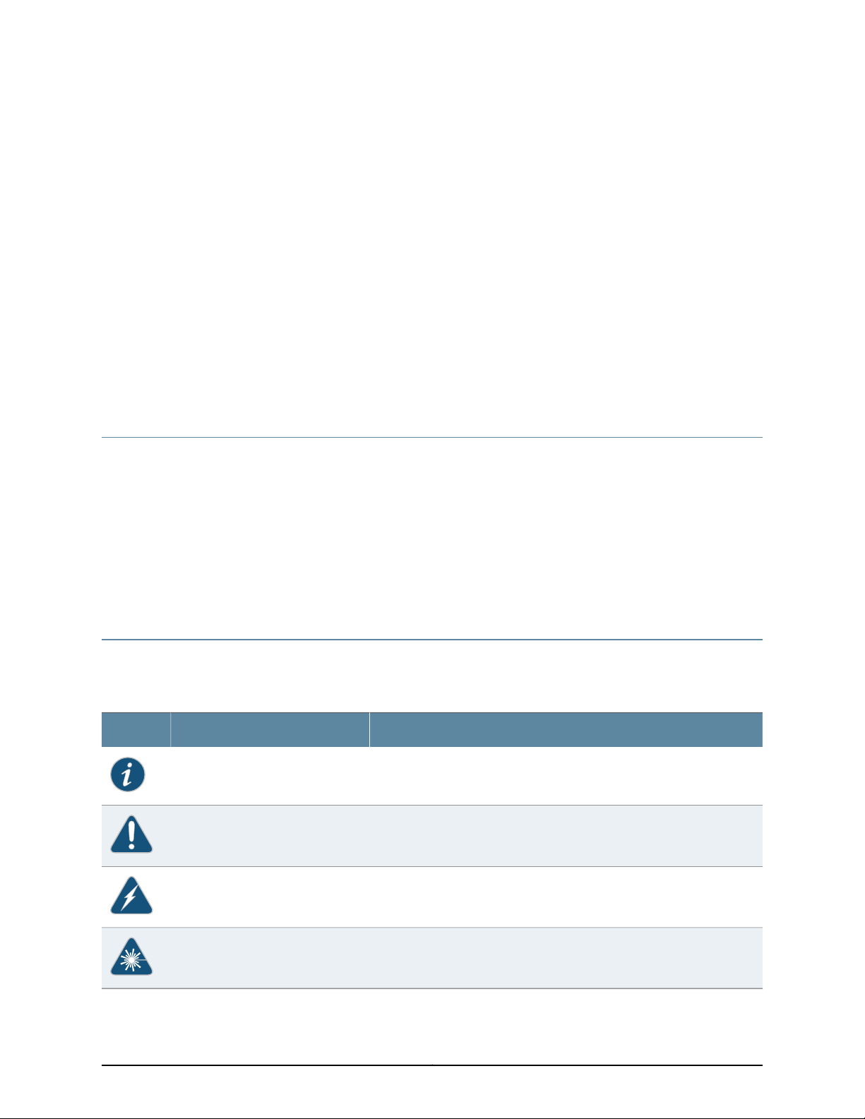
Table 1: Notice Icons
Table 1 on page xxi defines the notice icons used in this guide.
DescriptionMeaningIcon
Indicates important features or instructions.Informational note
Indicates a situation that might result in loss of data or hardware damage.Caution
Alerts you to the risk of personal injury or death.Warning
Alerts you to the risk of personal injury from a laser.Laser warning
xxiCopyright © 2013, Juniper Networks, Inc.
Page 22

MX480 3D Universal Edge Router Hardware Guide
Table 2 on page xxii defines the text and syntax conventions used in this guide.
Table 2: Text and Syntax Conventions
ExamplesDescriptionConvention
Fixed-width text like this
Italic text like this
Italic text like this
Text like this
Represents text that you type.Bold text like this
Represents output that appears on the
terminal screen.
•
Introduces or emphasizes important
new terms.
•
Identifies book names.
•
Identifies RFC and Internet draft titles.
Represents variables (options for which
you substitute a value) in commands or
configuration statements.
Represents names of configuration
statements, commands, files, and
directories;configurationhierarchy levels;
or labels on routing platform
components.
To enter configuration mode, type
theconfigure command:
user@host> configure
user@host> show chassis alarms
No alarms currently active
•
A policy term is a named structure
that defines match conditions and
actions.
•
Junos OS SystemBasics Configuration
Guide
•
RFC 1997, BGP Communities Attribute
Configure the machine’s domain name:
[edit]
root@# set system domain-name
domain-name
•
To configure a stub area, include the
stub statement at the[edit protocols
ospf area area-id] hierarchy level.
•
The console port is labeled CONSOLE.
stub <default-metric metric>;Enclose optional keywords or variables.< > (angle brackets)
| (pipe symbol)
# (pound sign)
[ ] (square brackets)
Indention and braces ( { } )
; (semicolon)
Indicates a choice betweenthe mutually
exclusivekeywords or variables on either
side of the symbol. The set of choices is
often enclosed in parenthesesfor clarity.
same lineas theconfiguration statement
to which it applies.
Enclose a variable for which you can
substitute one or more values.
Identify a level in the configuration
hierarchy.
Identifies a leaf statement at a
configuration hierarchy level.
broadcast | multicast
(string1 | string2 | string3)
rsvp { # Required for dynamic MPLS onlyIndicates a comment specified on the
community name members [
community-ids ]
[edit]
routing-options {
static {
route default{
nexthop address;
retain;
}
}
}
Copyright © 2013, Juniper Networks, Inc.xxii
Page 23

Table 2: Text and Syntax Conventions (continued)
J-Web GUI Conventions
Bold text like this
Represents J-Web graphical user
interface (GUI) items you click or select.
About the Documentation
ExamplesDescriptionConvention
•
In the Logical Interfaces box, select
All Interfaces.
•
To cancel the configuration, click
Cancel.
> (bold right angle bracket)
Documentation Feedback
We encourage you to provide feedback, comments, and suggestions so that we can
improve the documentation. You can send your comments to
techpubs-comments@juniper.net, or fill out the documentation feedback form at
https://www.juniper.net/cgi-bin/docbugreport/ . If you are using e-mail, be sure to include
the following information with your comments:
•
Document or topic name
•
URL or page number
•
Software release version (if applicable)
Requesting Technical Support
Technical productsupport is available through the Juniper NetworksTechnical Assistance
Center (JTAC). If you are a customer with an active J-Care or JNASC support contract,
or are covered under warranty, and need post-sales technical support, you can access
our tools and resources online or open a case with JTAC.
Separates levels in a hierarchy of J-Web
selections.
In the configuration editor hierarchy,
select Protocols>Ospf.
•
JTAC policies—For a complete understanding of our JTAC procedures and policies,
review the JTAC User Guide located at
http://www.juniper.net/us/en/local/pdf/resource-guides/7100059-en.pdf .
•
Product warranties—For product warranty information, visit
http://www.juniper.net/support/warranty/ .
•
JTAC hours of operation—The JTAC centers have resources available 24 hours a day,
7 days a week, 365 days a year.
Self-Help Online Tools and Resources
For quick and easy problem resolution, Juniper Networks has designed an online
self-service portal called the Customer Support Center (CSC) that provides you with the
following features:
xxiiiCopyright © 2013, Juniper Networks, Inc.
Page 24

MX480 3D Universal Edge Router Hardware Guide
•
Find CSC offerings: http://www.juniper.net/customers/support/
•
Search for known bugs: http://www2.juniper.net/kb/
•
Find product documentation: http://www.juniper.net/techpubs/
•
Find solutions and answer questions using our Knowledge Base: http://kb.juniper.net/
•
Download the latest versions of software and review release notes:
http://www.juniper.net/customers/csc/software/
•
Search technical bulletins for relevant hardware and software notifications:
https://www.juniper.net/alerts/
•
Join and participate in the Juniper Networks Community Forum:
http://www.juniper.net/company/communities/
•
Open a case online in the CSC Case Management tool: http://www.juniper.net/cm/
To verifyservice entitlement by product serial number,use ourSerial Number Entitlement
(SNE) Tool: https://tools.juniper.net/SerialNumberEntitlementSearch/
Opening a Case with JTAC
You can open a case with JTAC on the Web or by telephone.
•
Use the Case Management tool in the CSC at http://www.juniper.net/cm/.
•
Call 1-888-314-JTAC (1-888-314-5822 toll-free in the USA, Canada, and Mexico).
For international or direct-dial options in countries without toll-free numbers, see
http://www.juniper.net/support/requesting-support.html.
Copyright © 2013, Juniper Networks, Inc.xxiv
Page 25

PART 1
MX480 3D Universal Edge Router
Overview
•
MX480 Router Overview on page 3
•
MX480 Hardware Components on page 7
1Copyright © 2013, Juniper Networks, Inc.
Page 26

MX480 3D Universal Edge Router Hardware Guide
Copyright © 2013, Juniper Networks, Inc.2
Page 27

CHAPTER 1
MX480 Router Overview
•
MX480 Router Description on page 3
•
MX480 Component Redundancy on page 4
MX480 Router Description
The MX480 3D Universal EdgeRouter is an Ethernet-optimized edge router thatprovides
both switching and carrier-class Ethernet routing. The MX480 router has a capacity of
up to 720 gigabits per second (Gbps), full duplex. The MX480 router enables a wide
range of business and residential applications andservices, includinghigh-speed transport
and VPN services, next-generation broadband multiplay services, and high-volume
Internet data center internetworking.
The MX480 chassis provides redundancy and resiliency. The hardware system is fully
redundant, including powersupplies, Routing Engines,and Switch Control Boards (SCBs).
The MX480 router is eight rack units (U) tall. Five routers can be stacked in a single
floor-to-ceilingrack, for increased port density perunit of floor space.The router provides
eight slots that can be populated with up to six Dense Port Concentrators (DPCs) or
Modular Port Concentrators (MPCs), three Flexible PIC Concentrators (FPCs), and two
SCBs. Each FPC holds up to two PICs and each MPC holds up to two Modular Interface
Cards (MICs).
Fully populated, the MX480 router provides an aggregate throughput of up to 720 Gbps,
with line-rate throughput on 72 10-Gigabit Ethernet ports, or oversubscribed forwarding
at a gross ratio of 3:4 on all 96 10-Gigabit Ethernet ports.
Each DPC includeseither two orfour Packet Forwarding Engines.Each Packet Forwarding
Engine enables a throughput of 10 Gbps. Many types of DPCs are available. For a list of
the DPCs supported, see the MX Series 3D Universal Edge Routers Line Card Guide.
The MX480 supports up to 3 FPCs containing up to 6 PICs or up to 6 MPCs containing
up to 12 MICs. For a list of the supported line cards, see the MX Series 3D Universal Edge
Routers Line Card Guide.
The connections between DPCs, FPCs, MPCs, and SCBs are organized in three groups:
•
Switchfabric—Connectsthe interface cards and provides for packet transport between
DPCs, FPCs, and MPCs.
3Copyright © 2013, Juniper Networks, Inc.
Page 28

MX480 3D Universal Edge Router Hardware Guide
•
Control plane—Gigabit Ethernet links between the combined SCBs/Routing Engines
and each DPC, FPC, or MPC. All board-to-board information is passed over Ethernet
except for low-level status and commands.
•
Management signals—Provide for low-level status diagnostic support.
Related
Documentation
MX480 Component Redundancy on page 4•
• MX480 Chassis Description on page 7
• MX480 Host Subsystem Description on page 26
• MX480 Craft Interface Description on page 37
• MX480 Power System Description on page 41
• MX480 Cooling System Description on page 47
• MX480 Router Physical Specifications on page 281
MX480 Component Redundancy
A fully configured router is designed so that no single point of failure can cause the entire
system to fail. Only a fully configured router provides complete redundancy. All other
configurations provide partial redundancy. The following major hardware components
are redundant:
•
Host subsystem—The host subsystemconsists of a Routing Engine functioningtogether
with an SCB. The router can have one or two host subsystems. If two host subsystems
are installed, one functions as the master and the other functions as the backup. If the
master host subsystem (or either of its components) fails, the backup can take over
as the master. To operate, each host subsystem requires a Routing Engine installed
directly into in an SCB.
If theRouting Enginesare configured for graceful switchover, the backup Routing Engine
automatically synchronizes itsconfigurationand state with the master Routing Engine.
Any update to the master Routing Engine state is replicated on the backup Routing
Engine. Ifthe backupRouting Engine assumes mastership, packet forwarding continues
through the router without interruption. For more information aboutgraceful switchover,
see the Junos OS System Basics Configuration Guide.
•
Power supplies—In the low-line (110 V) AC power configuration, the router contains
three or four AC power supplies, located horizontally at the rear of the chassis in slots
PEM0 through PEM3 (left to right). Each AC power supply provides power to all
components in the router. When three power supplies are present, they share power
almost equally within a fully populated system. Four AC power supplies provide full
power redundancy.If one power supplyfails or is removed,the remainingpower supplies
instantly assume the entire electrical load without interruption. Three power supplies
provide the maximum configuration with full power for as long as the router is
operational.
In the high-line (220 V) AC power configuration, the router contains two or four AC
power supplies located horizontally at the rear of the chassis in slots PEM0 through
Copyright © 2013, Juniper Networks, Inc.4
Page 29

Chapter 1: MX480 Router Overview
PEM3 (left to right). Each AC power supply provides power to all components in the
router. Whentwo ormore power suppliesare present,they sharepower almostequally
within afully populated system. FourAC power supplies provide fullpower redundancy.
If one power supply fails or is removed, the remaining power supplies instantly assume
the entireelectricalload withoutinterruption. Two power suppliesprovide the maximum
configuration with full power for as long as the router is operational.
In the DC configuration, two power supplies are required to supply power to a fully
configured router. One power supply supports approximately half of the components
in the router, and the other power supply supports the remaining components. The
addition of two power supplies provides full power redundancy. If one power supply
fails or is removed, the remaining power supplies instantly assume the entire electrical
load without interruption. Two power supplies provide the maximum configuration
with full power for as long as the router is operational.
•
Cooling system—Thecooling system has redundant components, which are controlled
by the host subsystem. If one of the fans fails, the host subsystem increases the speed
of the remaining fans to provide sufficient cooling for the router indefinitely.
Related
Documentation
• MX480 Router Description on page 3
• MX480 Chassis Description on page 7
5Copyright © 2013, Juniper Networks, Inc.
Page 30

MX480 3D Universal Edge Router Hardware Guide
Copyright © 2013, Juniper Networks, Inc.6
Page 31

CHAPTER 2
MX480 Hardware Components
•
MX480 Chassis Description on page 7
•
MX480 Midplane Description on page 9
•
MX480 Dense Port Concentrator (DPC) Overview on page 10
•
MX480 Modular Port Concentrator (MPC) Overview on page 13
•
MX480 Modular Interface Card (MIC) Overview on page 15
•
MX480 Flexible PIC Concentrator (FPC) Overview on page 16
•
MX480 PIC Overview on page 19
•
MX480 Application Services Modular Line Card (AS MLC) Overview on page 20
•
MX480 Application Services Modular Storage Card Overview on page 23
•
MX480 Application Services Modular Processing Card Overview on page 24
•
MX480 Host Subsystem Overview on page 25
•
MX480 Switch Control Board (SCB) Overview on page 26
•
MX480 Routing Engine Overview on page 32
•
MX480 Craft Interface Overview on page 36
•
MX480 Power Supply Overview on page 41
•
MX480 Cooling System Overview on page 47
•
MX480 Cable Management Brackets on page 49
MX480 Chassis Description
The router chassis is a rigid sheet metal structure that houses all the other router
components (see Figure 1 on page 8, Figure 2 on page 8, and Figure 3 on page 9). The
chassis measures 14.0 in. (35.6 cm) high, 17.45 in. (44.3 cm) wide, and 24.5 in. (62.2 cm)
deep (fromthe front to the rear of the chassis). The chassisinstalls in standard 800-mm
(or larger) enclosed cabinets, 19-in. equipment racks, or telco open-frame racks. Up to
five routers can be installed in one standard 48-U rack if the rack can handle their
combined weight, which can be greater than 818 lb (371.0 kg).
7Copyright © 2013, Juniper Networks, Inc.
Page 32

MX480 3D Universal Edge Router Hardware Guide
Figure 1: Front View of a Fully Configured Router Chassis
Figure 2: Rear View of a Fully Configured AC-Powered Router Chassis
Copyright © 2013, Juniper Networks, Inc.8
Page 33

Chapter 2: MX480 Hardware Components
Figure 3: Rear View of a Fully Configured DC-Powered Router Chassis
Related
Documentation
MX480 Router Description on page 3•
• MX480 Midplane Description on page 9
• MX480 Router Physical Specifications on page 281
MX480 Midplane Description
The midplane is located toward the rear of the chassis and forms the rear of the card
cage (see Figure 4 on page 10). The line cards and SCBs install into the midplane from
the front of the chassis, and the power supplies install into the midplane from the rear
of the chassis. The cooling system components also connect to the midplane.
The midplane performs the following major functions:
•
Data path—Data packets are transferred across the midplane between the line cards
through the fabric ASICs on the SCBs.
•
Power distribution—The router power supplies connect to the midplane, which
distributes power to all the router components.
•
Signal path—The midplane provides the signal path to the line cards, SCBs, Routing
Engines, and other system components for monitoring and control of the system.
9Copyright © 2013, Juniper Networks, Inc.
Page 34

MX480 3D Universal Edge Router Hardware Guide
Figure 4: Midplane
Related
Documentation
MX480 Router Description on page 3•
• MX480 Chassis Description on page 7
• MX480 Dense Port Concentrator (DPC) Description on page 10
• MX480 Modular Port Concentrator (MPC) Description on page 13
• MX480 Switch Control Board (SCB) Description on page 26
• MX480 Flexible PIC Concentrator (FPC) Description on page 16
• MX480 Power System Description on page 41
MX480 Dense Port Concentrator (DPC) Overview
•
MX480 Dense Port Concentrator (DPC) Description on page 10
•
MX480 Dense Port Concentrator (DPC) LEDs on page 12
MX480 Dense Port Concentrator (DPC) Description
A Dense Port Concentrator (DPC) is optimized for Ethernet density (see Figure 5 on
page 11). The DPC assembly combines packet forwarding and Ethernet interfaces on a
single board, with either two or four 10-Gbps Packet Forwarding Engines. Each Packet
Forwarding Engine consists of one I-chip for Layer 3 processing and one Layer 2 network
processor. The DPCs interface with thepower supplies and Switch Control Boards (SCBs).
The DPC slots are located in the front of the router (see Figure 5 on page 11). The router
has six dedicated DPC slots that are numbered 0 through 5. A DPC can be installed in
any DPC slot on the router. You can install any combination of DPC types in the router.
If aslot isnot occupiedby aDPC, a DPC blank panel must be installed to shieldthe empty
slot and to allow cooling air to circulate properly through the router.
Copyright © 2013, Juniper Networks, Inc.10
Page 35

OK/FAIL
TUNNEL
LINK
1/0
TUNNEL
LINK
0/0
TUNNEL
LINK
2/0
TUNNEL
LINK
3/0
OK/
F
AIL
0/0
0/5
2/0
2/5
1/0
1/5
3/0
3/5
g004005
DPC 40x1GE DPC 4x10GE
Chapter 2: MX480 Hardware Components
DPCs are hot-removable and hot-insertable, as described in “MX480 Field-Replaceable
Units (FRUs)” on page 161. When you install a DPC in an operating router, the Routing
Engine downloads the DPC software, the DPC runs its diagnostics, and the Packet
Forwarding Engines housed on the DPC areenabled. Forwarding onother DPCscontinues
uninterrupted during this process.
Figure 5 on page 11 shows typical DPCs supported on the MX480 router. For more
information about DPCs, see the MX Series 3D Universal Edge Routers Line Card Guide.
Figure 5: Typical DPCs Supported on the Router
Figure 6: DPC Installed Horizontally in the Router
11Copyright © 2013, Juniper Networks, Inc.
Page 36

MX480 3D Universal Edge Router Hardware Guide
DPC Components
Each DPC consists of the following components:
•
DPC cover, which functions as a ground plane and a stiffener.
•
Fabric interfaces.
•
Two Gigabit Ethernet interfaces that allow control information, route information, and
statistics to be sent between the Routing Engine and the CPU on the DPCs.
•
Two interfaces from the SCBs that enable the DPCs to be powered on and controlled.
•
Physical DPC connectors.
•
Two or four Packet Forwarding Engines.
•
Midplane connectors and power circuitry.
•
Processor subsystem, which includes a 1.2-GHz CPU, system controller, and 1 GB of
SDRAM.
•
Online button—Takes the DPC online or offline when pressed.
•
LEDs on the DPC faceplate. For more information about LEDs on the DPC faceplate,
see the MX Series 3D Universal Edge Routers Line Card Guide.
Two LEDs, located on the craft interface above the DPC, display the status of the DPC
and are labeled OK and FAIL.
Related
Documentation
MX480 Dense Port Concentrator (DPC) LEDs on page 12•
• DPC and MPC LEDs on the MX480 Craft Interface on page 39
• Replacing an MX480 DPC on page 190
MX480 Dense Port Concentrator (DPC) LEDs
Two LEDs, located on the craft interface above the DPC, display the status of the DPC
and are labeled OK and FAIL. For more information about the DPC LEDs on the craft
interface, see “DPC and MPC LEDs on the MX480 Craft Interface” on page 39.
Each DPC also has LEDs located on the faceplate. For more information about LEDs on
the DPC faceplate, see the “LEDs” section for each DPC in the MX Series 3D Universal Edge
Routers Line Card Guide.
Related
Documentation
MX480 Dense Port Concentrator (DPC) Description on page 10•
• Maintaining MX480 DPCs on page 130
• Replacing an MX480 DPC on page 190
Copyright © 2013, Juniper Networks, Inc.12
Page 37

MX480 Modular Port Concentrator (MPC) Overview
•
MX480 Modular Port Concentrator (MPC) Description on page 13
•
MX480 Modular Port Concentrator (MPC) LEDs on page 15
MX480 Modular Port Concentrator (MPC) Description
Modular Port Concentrators (MPCs) provide packet forwarding services. The MPCs are
inserted into a slot in a router. Modular Interface Cards (MICs) provide the physical
interfaces and install into the MPCs. You can install up to two MICs of different media
types on the same MPC as long as the MPC supports those MICs.
A specialized fixed configuration MPC provideshigher portdensity over MICsand combines
packet forwarding and Ethernet interfacesonto a single line card. The fixed configuration
MPC is inserted into a slot in a router and contains no slots for MICs.
MICs receive incoming packets from the network and transmit outgoing packets to the
network. During this process, each MIC performs framing and high-speed signaling for
its media type. Before transmitting outgoing data packets through the MIC interfaces,
the MPCs encapsulate the packets received. Each MPC is equipped with up to four Junos
Trio chipsets, which perform control functions tailored to the MPC’s media type. The
MPCs interface with the power supplies and Switch Control Boards (SCBs). You must
install redundant SCBs to support full line-rate.
Chapter 2: MX480 Hardware Components
The MX480 router supports up to six MPCs. You must install a high-capacity fan tray to
use an MPC. For power requirements, see “Calculating Power Requirements for MX480
Routers” on page 285.
The router has six dedicated line card slots for DPCs, MPCs, or FPCs that are numbered
0 through 5 bottom to top. AnMPC canbe installedin anyslot onthe routerthat supports
MPCs. You can install any combination of line card types in the router.
When a slot is not occupied by an MPC or other line card, you must insert a blank DPC
panel to fill the empty slot and ensure proper cooling of the system.
MPCs are hot-removable and hot-insertable. When you install an MPC in an operating
router, the Routing Engine downloads the MPC software, the MPC runs its diagnostics,
and thePacketForwarding Engineshoused onthe MPCare enabled. Forwarding onother
MPCs continues uninterrupted during this process.
Figure 8 on page 14 shows a typical MPC supported on the MX480 router. For more
information about MPCs, see the MX Series 3D Universal Edge Routers Line Card Guide.
13Copyright © 2013, Juniper Networks, Inc.
Page 38

g004902
MPC (empty)
OK
MASTER
FAN
ONLINE
OFFLINE
0
1
1
0
FAIL
FAIL
PEM
FAIL
FAIL
FAIL
FAIL
FAIL
FAIL
ESD
OK
OK
OK
OK
OK
OK
OK
2
3
4
5
ACO/LT
YELLOWALARM
REDALARM
NC
NO
C
NC
NO
C
MX480
REO
RE1
0
1
2
3
SCB
SCB
g004909
MPC
MX480 3D Universal Edge Router Hardware Guide
Figure 7: Typical MPC Supported on the MX Series Router
Figure 8: MPC Installed Horizontally in the MX480 Router
MPC Components
Each MPC consists of the following components:
•
MPC card carrier, which includestwo MIC slots (excludes thefixed configuration MPC).
•
Fabric interfaces.
•
Two Gigabit Ethernet interfaces that allow control information, route information, and
statistics to be sent between the Routing Engine and the CPU on the MPCs.
•
Two interfaces from the SCBs that enable the MPCs to be powered on and controlled.
Copyright © 2013, Juniper Networks, Inc.14
Page 39

Chapter 2: MX480 Hardware Components
•
Physical MPC connectors.
•
Up to four Junos Trio chipsets, which perform control functions tailored to the MPC’s
media type.
•
Midplane connectors and power circuitry.
•
Processor subsystem, which includes a 1.5-GHz CPU, system controller, and 1 GB of
SDRAM.
•
Online button which takes the MPC online or offline when pressed.
•
OK/Fail LED on the MPC faceplate. For more information about LEDs on the MPC
faceplate, see the MX Series 3D Universal Edge Routers Line Card Guide.
Two LEDs, located on the craft interface above the MPC, display the status of the line
cards and are labeled OK and FAIL.
Related
Documentation
MPCs Supported by MX240, MX480, and MX960 Routers•
• MX480 Modular Port Concentrator (MPC) LEDs on page 15
• MX480 Field-Replaceable Units (FRUs) on page 161
• Replacing an MX480 MPC on page 203
MX480 Modular Port Concentrator (MPC) LEDs
Two LEDs, located on the craft interface above the MPC, display the status of the line
cards and are labeled OK and FAIL. For more information about the line card LEDs on the
craft interface, see “DPC and MPC LEDs on the MX480 Craft Interface” on page 39.
Each MPC also has LEDs located on the faceplate. For more information about LEDs on
the MPC faceplate, see the “LEDs” section for each MPC in the MX Series 3D Universal
Edge Routers Line Card Guide.
Related
Documentation
MX480 Modular Port Concentrator (MPC) Description on page 13•
• Maintaining MX480 MPCs on page 135
• Troubleshooting the MX480 MPCs on page 156
• Replacing an MX480 MPC on page 203
MX480 Modular Interface Card (MIC) Overview
•
MX480 Modular Interface Card (MIC) Description on page 15
•
MX480 Modular Interface Card (MIC) LEDs on page 16
MX480 Modular Interface Card (MIC) Description
Modular Interface Cards (MICs) install into Modular Port Concentrators (MPCs) and
provide the physical connections to various network media types. MICs allow different
physical interfaces to be supported on a single line card. You can install MICs of different
media types on the MPC as long as the MPC supports those MICs.
15Copyright © 2013, Juniper Networks, Inc.
Page 40

MX480 3D Universal Edge Router Hardware Guide
MICs receive incoming packets from the network and transmit outgoing packets to the
network. During this process, each MIC performs framing and high-speed signaling for
its media type. Before transmitting outgoing data packets through the MIC interfaces,
the MPCs encapsulate the packets received.
MICs are hot-removable and hot-insertable. You can install up to two MICs in the slots
in each MPC.
Related
Documentation
MICs Supported by MX Series Routers•
• MX480 Modular Interface Card (MIC) LEDs on page 16
• Maintaining MX480 MICs on page 137
• Troubleshooting the MX480 MICs on page 158
• Replacing an MX480 MIC on page 208
MX480 Modular Interface Card (MIC) LEDs
Each MIC has LEDs located on the faceplate. For more information about LEDs on the
MIC faceplate, see the “LEDs” section for each MIC in the MX Series 3D Universal Edge
Routers Line Card Guide.
Related
Documentation
MICs Supported by MX Series Routers•
• MX480 Modular Interface Card (MIC) Description on page 15
• Maintaining MX480 MICs on page 137
• Troubleshooting the MX480 MICs on page 158
• Replacing an MX480 MIC on page 208
MX480 Flexible PIC Concentrator (FPC) Overview
•
MX480 Flexible PIC Concentrator (FPC) Description on page 16
•
MX480 Flexible PIC Concentrator (FPC) LEDs on page 18
•
FPCs Supported by the MX480 Router on page 19
MX480 Flexible PIC Concentrator (FPC) Description
A Flexible PIC Concentrator (FPC) occupies two DPC slots on an MX Series router. The
router has six dedicated DPC slots that are numbered 0 through 5, bottom to top. Up to
three FPCs can be installed horizontally on the front of the router (see Figure 9 on
page 17). The interface corresponds to the lowest numbered DPC slot for which the FPC
is installed.
Copyright © 2013, Juniper Networks, Inc.16
Page 41

OK
MASTER
F
AN
ONLINE
OFFLINE
0
1
1
0
F
AI
L
F
AI
L
PEM
F
AI
L
F
AI
L
F
AI
L
F
AI
L
F
AI
L
F
A
I
L
ESD
OK
OK
OK
OK
OK
OK
OK
2
3
4
5
ACO
/
L
T
Y
EL
L
OW
ALAR
M
RED
ALARM
NC
N
O
C
N
C
NO
C
MX480
REO
RE1
0
1
2
3
g004414
g004417
DPCE-X-Q-40GE
DPCE-X-Q-40GE
FPC3MX-FPC2
MX-FPC2
Chapter 2: MX480 Hardware Components
Figure 9: FPC Installed in the MX480 Router Chassis
Figure 10 on page 17 shows the typical FPCs supported on the MX480 router.
Figure 10: Typical FPCs Supported on the MX480 Router
If a slot is not occupied by a DPC, an FPC, or an SCB, a blank panel must be installed to
shield the empty slot and to allow cooling air to circulate properly through the router.
Each FPC supports up to two PICs. On an FPC2, one Packet Forwarding Engine receives
incoming packets from the PICs installed on the FPC and forwards them through the
switch planes to the appropriate destination port. On an FPC3, two Packet Forwarding
17Copyright © 2013, Juniper Networks, Inc.
Page 42

MX480 3D Universal Edge Router Hardware Guide
Engines receive incoming packets from the PICs installed on the FPC and forwards them
through the switch planes to the appropriate destination port. The FPCs interface with
the power supplies and SCBs.
FPCs are hot-removable and hot-insertable, as described in “MX480 Component
Redundancy” on page 4. When you install an FPC into a functioning router, the Routing
Engine downloads the FPC software, the FPC runs its diagnostics, and the PICs, housed
on the FPC, are enabled. Forwarding continues uninterrupted during this process. When
you remove or install an FPC, packet forwarding between other DPCs or FPCs is not
affected.
FPC Components
Each FPC consists of the following components:
•
FPC card carrier, which includes two PIC slots
•
Up to two Packet Forwarding Engines, each consisting of one I-chip for Layer 3
processing and one Layer 2 network processor
•
Midplane connectors and power circuitry
•
Processor subsystem (PMB), which includes a 1.2-GHz CPU, system controller, 1 GB of
SDRAM, and two Gigabit Ethernet interfaces
•
Two LEDs, located on the craft interface above the FPC, that display the status of the
FPC and are labeled OK and FAIL
•
FPC online/offline button, located on the craft interface above the FPC
Related
Documentation
MX480 Flexible PIC Concentrator (FPC) LEDs on page 18•
• Maintaining MX480 FPCs on page 132
• MX480 FPC Terminology on page 143
• Troubleshooting the MX480 FPCs on page 154
• Replacing an MX480 FPC on page 194
MX480 Flexible PIC Concentrator (FPC) LEDs
Two LEDs, located on the craft interface above the FPC, that display the status of the
FPC and are labeled OK and FAIL. For more information about the FPC LEDs located on
the craft interface, see “FPC LEDs on the MX480 Craft Interface” on page 39.
Related
Documentation
MX480 Flexible PIC Concentrator (FPC) Description on page 16•
• Maintaining MX480 FPCs on page 132
• MX480 FPC Terminology on page 143
• Troubleshooting the MX480 FPCs on page 154
• Replacing an MX480 FPC on page 194
Copyright © 2013, Juniper Networks, Inc.18
Page 43

FPCs Supported by the MX480 Router
An FPC occupies two slots when installed in an MX Series router. The MX480 router
supports up to three FPCs. Table 3 on page 19 lists FPCs supported by MX Series routers.
Table 3: FPCs Supported by MX480 Routers
Chapter 2: MX480 Hardware Components
Related
Documentation
• Maintaining MX480 FPCs on page 132
• MX480 FPC Terminology on page 143
• Troubleshooting the MX480 FPCs on page 154
• Replacing an MX480 FPC on page 194
MX480 PIC Overview
•
•
MX480 PIC Description
Maximum
Number of PICs
SupportedFPC Model NumberFPC NameFPC Type
MX480 Flexible PIC Concentrator (FPC) LEDs on page 18•
MX480 PIC Description on page 19
MX480 PIC LEDs on page 20
Maximum
Throughputper FPC
(Full-duplex)
First Junos OS
Release
9.420 Gbps2MX-FPC3FPC33
9.510 Gbps2MX-FPC2FPC22
Related
Documentation
PICs provide the physical connection to various network media types, receiving incoming
packets from the network and transmitting outgoing packets to the network. During this
process, each PIC performs framing and line-speed signaling for its media type. Before
transmitting outgoing data packets, the PICs encapsulate the packets received from the
FPCs. Each PIC is equipped with an ASIC that performs control functions specific to the
media type of that PIC.
PICs are hot-removable and hot-insertable. Up to two PICs can be installed in the slots
in each FPC. Up to three FPCs can be installed in an MX480 router. PICs used in a Type
2 FPC have captive screws at their upper and lower corners. PICs used in a Type 3 FPC
have an upper ejector handle and a lower captive screw.
PICs Supported by MX240, MX480, and MX960 Routers•
• Replacing an MX480 PIC on page 199
19Copyright © 2013, Juniper Networks, Inc.
Page 44

MX480 3D Universal Edge Router Hardware Guide
MX480 PIC LEDs
Each PIC has LEDs located on the faceplate. For more information about LEDs on the
PIC faceplate, see the “LEDs” section for each PIC in the MX Series 3D Universal Edge
Routers Line Card Guide.
Related
Documentation
PICs Supported by MX240, MX480, and MX960 Routers•
• MX480 PIC Description on page 19
• Replacing an MX480 PIC on page 199
• Maintaining MX480 PICs on page 134
MX480 Application Services Modular Line Card (AS MLC) Overview
•
MX480 Application Services Modular Line Card Description on page 20
MX480 Application Services Modular Line Card Description
The Application Services Modular Line Card (AS MLC) is an X86-based card for MX960,
MX480, and MX240 routers to deliver integrated application service solutions. The first
application that network operators can take advantage of is the Junos Content Encore
system, a high-throughput, solid state storage platform for media rich content delivery.
Additionally, the AS MLC can serve as the platform for Juniper Networks JunosV App
Engine, powering a host of network applications directly embedded into your MX Series
3D Universal Edge Routers.
The AS MLC is modular and decouples CPU and storage in individual field-upgradeable
units. The AS MLCs are designed to enable application throughput up to 80 Gbps and a
storage capacity of 8 terabytes (TB) of NAND Flash, with up to 6.4 TB usable storage.
Copyright © 2013, Juniper Networks, Inc.20
Page 45

g006671
Chapter 2: MX480 Hardware Components
Figure 11: Application Services Modular Line Card (AS MLC)
MX480 AS MLC Function
The AS MLC provides modular processing and modular storage. Installed on the AS MLC,
the Junos Content Encore system operates as a caching application, in either HTTP
reverse proxy mode or HTTP transparent proxy mode, to manage client requests for
content and the distribution of the content to clients from origin servers. In the future,
the AS MLC will run other Juniper Networks router services and applications, and serve
as a virtualized platform for third-party applications. The AS MLC provides Ethernet
switching and high-speed fabric interface to MX routers. Graceful Routing Engine
switchover is also supported on the AS MLC.
Integrated with application forwarding on MX Series routers, the AS MLC provides
increased service flexibility with reduced power and space requirements for the network
infrastructure.
AS MLC Components
Each AS MLC consists of the following components:
•
AS MLC Modular Carrier Card (AS MCC), which fits horizontally in front of the MX480
router, includes two slots for the Application Services Modular Storage Card (AS MSC)
and Application Services Modular Processing Card (AS MXC)
•
AS MXC with 64 GB RAM for processing
•
AS MSC with 6.4 TB NAND Flash capacity for modular storage
NOTE: The AS MCC, AS MXC, and AS MSC are hot-removable and
hot-insertable.
21Copyright © 2013, Juniper Networks, Inc.
Page 46

MX480 3D Universal Edge Router Hardware Guide
•
Switch fabric interfaces to the chassis
•
XM ASIC chip, which owns and manages the packet data memory built from external
DDR3 memory chips, the fabric queuing system, a portion of the WAN queuing system,
and the host queuing system
•
LU ASIC chip, which performs all functions relating to headerprocessing including input
processing, route lookup, classification, filtering, policing, accounting, encapsulation,
and statistics
•
Midplane connectors and power circuitry
•
Processor Mezzanine Board (PMB), which contains the host processor and supporting
peripherals.
•
LED on the AS MCC, which displays the status of the AS MLC
MX480 SCB, Power Supply, and Cooling System Requirements for AS MLC
Each MX480 router requires specific SCB, power supply, and cooling system models to
run the AS MLC:
Related
Documentation
•
SCB—Enhanced MX SwitchControl Board (SCBE-MX). See “MX480 Enhanced Switch
Control Board Description” on page 29 for details
•
Power supply:
•
2520W AC power supply—Model PWR-MX480-2520-AC
•
2400W DC power supply—Model PWR-MX480-2400-DC
•
Power requirement for AS MLC:
•
AS MCC—191W
•
AS MXC—259W
•
AS MSC—50W
•
Cooling system—Required fan and fan tray models:
•
Fans:
•
For AC power supply: PWR-FAN-MX480-AC-HC-U and PWR-MX480-2520-AC-S
•
For DCpowersupply: PWR-FAN-MX480-DC-HC-U and PWR-MX480-2520-DC-S
•
Fan tray—FFANTRAY-MX480-HC
Replacing an MX480 AS MLC on page 214•
• Replacing an MX480 AS MSC on page 217
• Replacing an MX480 AS MXC on page 220
Copyright © 2013, Juniper Networks, Inc.22
Page 47

g006673
Chapter 2: MX480 Hardware Components
MX480 Application Services Modular Storage Card Overview
•
MX480 Application Services Modular Storage Card Description on page 23
•
MX480 AS MSC LEDs on page 24
MX480 Application Services Modular Storage Card Description
Application Services Modular Storage Card (AS MSC) is aNAND Flash––based card that
is inserted into the upper slot of the Application Services Modular Line Card (AS MLC).
The AS MSC (see Figure 12 on page 23) serves as the second tier caching storage for
platforms such as the Junos Content Encore system. This card is equivalent to a PIC or
a Modular Interface Card (MIC) and provides a maximum of 36 Gbps read and 2 Gbps
of write memory.
The AS MSC has the following features:
•
6.4 TB NAND Flash memory
•
Up to 48K of write cycle
•
Multilevel cell (MLC) NAND memory support
•
Best-in-class NAND controller for maximum performance and reliability
AS MSCs are hot-removable and hot-insertable. One AS MSC can be installed in the top
slot of each AS MLC. Each AS MSC has these components:
•
SATA-3 controller—An eight-port, 6 Gbps SAS/SATA controller.
•
NAND Flash controller—Each controller can access 512 GB, and eight controllers
communicate with one Raid on chip (ROC). NAND Flash and NAND Flash controller
are used in an AS MSC.
•
Control plane—Inter-integrated circuit control plane thatallowsPeripheral Component
Interconnect Express (PCIe) control.
•
LEDs—Two LEDs display the status of the AS MSC and storage.
•
Online/offline button—To power on or power off the AS MSC.
Figure 12: Application Services Modular Storage Card
23Copyright © 2013, Juniper Networks, Inc.
Page 48

MX480 3D Universal Edge Router Hardware Guide
Related
Documentation
MX480 AS MSC LEDs
MX480 AS MSC LEDs on page 24•
• Replacing an MX480 AS MSC on page 217
Two LEDs (CPU and AP) indicate the status of the AS MSC and are located on the AS
MSC. Table 4 on page 24 describes the functions of the AS MSC LEDs.
Table 4: AS MSC LEDs
DescriptionStateColorLabel
AS MSC operates normally.On steadilyGreenCPU
AS MSC has an error or has failed.On steadilyRed
AS MSC is offline.Off–
AS MSC storage operation is normal.On steadilyGreenAP
AS MSC storage operation has an error.On steadilyRed
AS MSC storage operation is not activated.Off–
Related
Documentation
MX480 Application Services Modular Storage Card Description on page 23•
• Replacing an MX480 AS MSC on page 217
MX480 Application Services Modular Processing Card Overview
•
MX480 Application Services Modular Processing Card Description on page 24
•
MX480 AS MXC LEDs on page 25
MX480 Application Services Modular Processing Card Description
The Application Services Modular Processing Card (AS MXC) is a pluggable X86-based
card that can be inserted into the lower slot of the Application Services Modular Line
Card (AS MLC). The AS MXC serves as the processing card for the Junos Content Encore
system and contains the two X86, Intel 8-core processors with interface ability greater
than 80 Gbps. The AS MXC (see Figure 13 on page 25) is equivalent to a PIC or MIC
(Modular Interface Card).
AS MXCs are hot-removable and hot-insertable. One MXC can be installed in the lower
slot of each AS MLC. Each MXC has these components:
•
Two 8-core Intel processors—Contains eight execution cores with Ring Interconnect
architecture. Each core supports two threads, up to 16 threads per socket.
•
64 GB DRAM—On DIMM sockets.
Copyright © 2013, Juniper Networks, Inc.24
Page 49

g006672
Chapter 2: MX480 Hardware Components
•
LEDs—Two LEDs on the faceplate display the CPU and application status.
Figure 13: Application Services Modular Processing Card (AS MXC)
Related
Documentation
MX480 AS MXC LEDs
MX480 AS MXC LEDs on page 25•
• Replacing an MX480 AS MXC on page 220
Two LEDs (CPU and AP) indicate the status of the AS MXC and are located on the AS
MXC. Table 5 on page 25 describes the functions of the AS MXC LEDs.
Table 5: AS MXC LEDs
DescriptionStateColorLabel
AS MXC operates normally.On steadilyGreenCPU
AS MXC has an error or has failed.On steadilyRed
AS MXC is offline.Off–
AS MXC applications operation is normal.On steadilyGreenAP
AS MXC applications operation has an error.On steadilyRed
AS MXC applications are not activated.Off–
Related
Documentation
MX480 Application Services Modular Processing Card Description on page 24•
• Replacing an MX480 AS MXC on page 220
MX480 Host Subsystem Overview
•
MX480 Host Subsystem Description on page 26
•
MX480 Host Subsystem LEDs on page 26
25Copyright © 2013, Juniper Networks, Inc.
Page 50

MX480 3D Universal Edge Router Hardware Guide
MX480 Host Subsystem Description
The host subsystem provides the routing and system management functions of the
router. You can install one or two host subsystems on the router. Each host subsystem
functions as a unit; the Routing Engine must be installed directly into the Switch Control
Board.
NOTE: We recommend that you install two host subsystems for redundant
protection. If you install only one host subsystem, we recommend that you
install it in slot 0.
Each host subsystem has three LEDs that display its status. The host subsystem LEDs
are located on the upper left of the craft interface.
Related
Documentation
MX480 Host Subsystem LEDs on page 26•
• Maintaining the MX480 Host Subsystem on page 128
• Taking an MX480 Host Subsystem Offline on page 172
MX480 Host Subsystem LEDs
Each host subsystem has three LEDs that display its status. The host subsystem LEDs
are located on the upper left of the craft interface. For more information, see “Host
Subsystem LEDs on the MX480 Craft Interface” on page 38.
Related
Documentation
MX480 Host Subsystem Description on page 26•
• Maintaining the MX480 Host Subsystem on page 128
• Taking an MX480 Host Subsystem Offline on page 172
MX480 Switch Control Board (SCB) Overview
•
MX480 Switch Control Board (SCB) Description on page 26
•
MX480 Switch Control Board (SCB) LEDs on page 28
•
MX480 Enhanced Switch Control Board Description on page 29
•
MX480 Enhanced Switch Control Board LEDs on page 30
MX480 Switch Control Board (SCB) Description
The Switch Control Board (SCB) provides the following functions::
•
Powers on and powers off DPCs, FPCs, and MPCs
•
Controls clocking, system resets, and booting
Copyright © 2013, Juniper Networks, Inc.26
Page 51

Chapter 2: MX480 Hardware Components
•
Monitors and controls system functions,including fanspeed, board power status, PDM
status and control, and the craft interface
•
Provides interconnections to all the DPCs, FPCs, and MPCs within the chassis through
the switch fabrics integrated into the SCB
The Routing Engine installs directly into a slot on the SCB (see Figure 14 on page 27).
Figure 14: SCB
SCB Slots
You can install one or two. The SCBs install horizontally into the front of the chassis in
the slots labeled 0 and 1. If any slots are empty, you must install a blank panel.
SCB Redundancy
If two SCBs are installed, one SCB functions as the master SCB and the other as its
backup. If the master fails or is removed, the backup restarts and becomes the master.
SCB Components
Each SCB consists of the following components:
•
Chassis management Ethernet switch
•
I2C bus logic, used for low-level communication with each component
•
Component redundancy circuitry
•
Control Board/Routing Engine mastership mechanism
•
Gigabit Ethernet switch that is connected to the embedded CPU complex on all
components
27Copyright © 2013, Juniper Networks, Inc.
Page 52

MX480 3D Universal Edge Router Hardware Guide
•
Switch fabric—Provides the switching functions for the DPCs, FPCs, and MPCs
•
Control field-programmable gate array (FPGA)—Provides the Peripheral Component
Interconnect (PCI) interface to the Routing Engine
•
1000Base-T Ethernet controller—Providesa 1-Gbps Ethernet link between the Routing
Engines
•
Ethernet switch—Provides 1-Gbps link speeds between the Routing Engine and the
DPCs, FPCs, and MPCs
•
Circuits for chassis management and control
•
Power circuits for the Routing Engine and SCB
•
LEDs—Provide status
Related
Documentation
MX480 Host Subsystem Description on page 26•
• MX480 Routing Engine Description on page 32
• MX480 Switch Control Board (SCB) LEDs on page 28
MX480 Switch Control Board (SCB) LEDs
Three LEDs on the SCB indicate the status of the SCB. The LEDs, labeled FABRIC ACTIVE,
FABRICONLY, andOK/FAIL, are located directly on the SCB. Table 6on page28 describes
the functions of the SCB LEDs.
Table 6: SCB LEDs
ACTIVE
ONLY
DescriptionStateColorLabel
Fabric is in active mode.On steadilyGreenFABRIC
SCB operates in fabric-only mode.On steadilyGreenFABRIC
SCB operates in fabric/control board mode.Off–
SCB is online.On steadilyGreenOK/FAIL
SCB has failed.On steadilyRed
Related
Documentation
SCB is offline.Off–
Each SCB also has two LEDs on the craft interface that indicate its status. The SCB LEDs,
labeled 0 and 1, are located along the bottom of the craft interface. For more information
about the SCB LEDs on the craft interface, see “SCB LEDs on the MX480 Craft Interface”
on page 40.
MX480 Switch Control Board (SCB) Description on page 26•
• MX480 Host Subsystem Description on page 26
Copyright © 2013, Juniper Networks, Inc.28
Page 53

• Replacing an MX480 SCB on page 174
g006589
SCBE-MX
MX480 Enhanced Switch Control Board Description
The Enhanced MX Switch Control Board (MX SCBE) serves the carrier Ethernet services
router and carrier Ethernet transport markets that require higher-capacity traffic support
demanding greater interface density (slot and capacity scale), as well as improved
services. The upgraded SCB is supported on MX960, MX480, and MX240 routers. Some
key attributes of the Enhanced MX SCB are:
•
160 Gbps/slot bandwidth with redundant fabric support, and improved fabric
performance by using the next-generation fabric (XF) chip
•
A central clocking module and a centralized clocking architecture that supports clock
cleanup and distribution. The Stratum 3 clock module performs clock monitoring,
filtering, and holdover in a centralized chassis location
•
Full performance with fabric redundancy for highercapacity line cardssuch as16x10GE
and MPC3
Chapter 2: MX480 Hardware Components
The Routing Engine installs directly into a slot on the MX SCBE (see Figure 15 on page 29).
Figure 15: MX SCBE
29Copyright © 2013, Juniper Networks, Inc.
Page 54

MX480 3D Universal Edge Router Hardware Guide
MX SCBE Slots
You can install one or two MX SCBEs. The MX SCBEs install horizontally into the front
of the chassis in the slots labeled 0 and 1. If any slots are empty, you must install a blank
panel.
MX SCBE Redundancy
If two MX SCBEs are installed, one MX SCBE functions as the master MX SCBE and the
other as its backup. If the master fails or is removed, the backup restarts and becomes
the master.
MX SCBE Components
Each MX SCBE consists of the following components:
•
I2C bus logic, used for low-level communication with each component
•
Component redundancy circuitry
•
Control Board/Routing Engine mastership mechanism
•
Gigabit Ethernet switch that is connected to the embedded CPU complex on all
components
•
External clock interface—Allows BITS or GPS clock source input to the centralized
timing circuit, or allows centralized timing to be output to BITS or GPS
•
Switch fabric—Provides the switching functions for the DPCs, FPCs, and MPCs
•
Control field-programmable gate array (FPGA)—Provides the Peripheral Component
Interconnect (PCI) interface to the Routing Engine
•
1000Base-T Ethernet controller—Providesa 1-Gbps Ethernet link between the Routing
Engines
•
Circuits for chassis management and control
•
Power circuits for the Routing Engine and SCBE
•
LEDs—Provide status of the SCBE and clocking interface
Related
Documentation
MX480 Switch Control Board (SCB) Description on page 26•
• MX480 Enhanced Switch Control Board LEDs on page 30
• Upgrading an MX480 SCB on page 177
MX480 Enhanced Switch Control Board LEDs
The FABRIC ACTIVE, FABRIC ONLY, and OK/FAIL LEDs indicate the status of the SCBE.
The BITS, GPS, and UTI LEDs, located next to the EXT CLK port, indicate the status of the
respective clocking interface. Table 7 on page 31 describes the functions of the Enhanced
MX SCB (MX SCBE) LEDs.
Copyright © 2013, Juniper Networks, Inc.30
Page 55

Table 7: Enhanced MX SCB LEDs
ACTIVE
ONLY
Chapter 2: MX480 Hardware Components
DescriptionStateColorLabel
Fabric is in active mode.On steadilyGreenFABRIC
MX SCBE operates in fabric-only mode.On steadilyGreenFABRIC
MX SCBE operates in fabric/control board mode.Off–
MX SCBE is online.On steadilyGreenOK/FAIL
MX SCBE has failed.On steadilyRed
MX SCBE is offline.Off–
GPS clocking interface has failed.On steadilyRed
GPS clocking interface is offline.Off–
Related
Documentation
NOTE: The LEDs BITS, GPS, and UTI are not currently supported.
On steadilyGreenBITS
On steadilyGreenGPS
On steadilyGreenUTI
Building-integrated timing supply (BITS) clocking
interface is active.
BITS clocking interface has failed.On steadilyRed
BITS clocking interface is offline.Off–
Global positioning system (GPS) clocking interface
is active.
GPS clocking interface has failed.On steadilyRed
GPS clocking interface is offline.Off–
Universal Timing Interface (UTI) clocking interface
is active.
UTI clocking interface has failed.On steadilyRed
UTI clocking interface is offline.Off–
MX480 Enhanced Switch Control Board Description on page 29•
• MX480 Host Subsystem Description on page 26
• Upgrading an MX480 SCB on page 177
31Copyright © 2013, Juniper Networks, Inc.
Page 56

MX480 3D Universal Edge Router Hardware Guide
MX480 Routing Engine Overview
•
MX480 Routing Engine Description on page 32
•
RE-S-1800 Routing Engine Description for MX Series on page 34
•
RE-S-1800 Routing Engine LEDs on page 35
•
MX480 Routing Engine LEDs on page 36
MX480 Routing Engine Description
The Routing Engineis anIntel-basedPC platformthat runs JunosOS. Software processes
that runon the Routing Engine maintainthe routing tables, managethe routing protocols
used on the router, control the router interfaces, control some chassis components, and
provide the interface for system management and user access to the router.
You can install one or two Routing Engines in the router. The Routing Engines install into
the front of the chassis in horizontal slots in the SCBs labeled 0 and 1. If two Routing
Engines are installed, one functions as the master and the other acts as the backup. If
the master Routing Engine fails oris removed, and the backup is configured appropriately,
the backup takes over as the master.
The Routing Engines are hot-pluggable. Each Routing Engine must be installed directly
into an SCB. A USB port on the Routing Engine accepts a USB memory card that allows
you to load Junos OS.
Figure 16: Routing Engine
Routing Engine Components
NOTE: For specific information about Routing Engine components (for
example, the amount of DRAM), issue the show chassis routing-engine
command.
Copyright © 2013, Juniper Networks, Inc.32
Page 57

Chapter 2: MX480 Hardware Components
Routing Engine Interface Ports
Three ports, located on the right side of the routing engine, connect the Routing Engine
to one or more external devices on which system administrators can issue Junos OS
command-line interface (CLI) commands to manage the router.
The ports with the indicated labels function as follows:
•
AUX—Connects the Routing Engine to a laptop, modem, or other auxiliary device
through a serial cable with an RJ-45 connector.
•
CONSOLE—Connects the Routing Engine to a system console through a serial cable
with an RJ-45 connector.
•
ETHERNET—Connects the Routing Engine through an Ethernet connection to a
management LAN (or any other device that plugs into an Ethernet connection) for
out-of-band management. The port uses an autosensing RJ-45 connector to support
10-Mbps or 100-Mbps connections. Two small LEDs on the top of the port indicate the
connection in use: the LED flashes yellow or green for a 10-Mbps or 100-Mbps
connection, and the LED is light green when traffic is passing through the port.
Related
Documentation
Routing Engine Boot Sequence
The Routing Engine boots from the storage mediain this order: the USB device(if present),
then the CompactFlash card, then the hard disk, then the LAN. The disk from which the
router boots is called the primary boot device, and the other disk is the alternate boot
device.
NOTE: If the router boots froman alternateboot device,a yellow alarmlights
the LED on the router’s craft interface.
If the Routing Engines are configured for graceful switchover, the backup Routing Engine
automatically synchronizes its configuration and state with the master Routing Engine.
Any update to the master Routing Engine state is replicated onthe backup Routing Engine.
If the backup Routing Engine assumes mastership, packet forwarding continues through
the router without interruption. For more information about graceful switchover, see the
Junos OS System Basics Configuration Guide.
NOTE: If two Routing Engines are installed, they must both be the same
hardware model.
MX480 Router Description on page 3•
• MX480 Routing Engine LEDs on page 36
• MX480 Host Subsystem Description on page 26
• MX480 Switch Control Board (SCB) Description on page 26
33Copyright © 2013, Juniper Networks, Inc.
Page 58

g006040
USB
port
Reset
button
Extractor
clip
Extractor
clip
Console
port
Auxiliary
port
Ethernet
port
SSD
slot 2
SSD
slot 1
g006040
USB
port
Reset
button
Extractor
clip
Extractor
clip
Console
port
Auxiliary
port
Ethernet
port
SSD
slot 2
SSD
slot 1
MX480 3D Universal Edge Router Hardware Guide
RE-S-1800 Routing Engine Description for MX Series
Figure 17 on page 34 shows the Routing Engine 1800.
Figure 17: RE-S-1800 Front View
•
RE-S-1800 Routing Engine Components on page 34
•
RE-S-1800 Routing Engine Boot Sequence on page 35
RE-S-1800 Routing Engine Components
Figure 18 on page 34 shows the RE-S-1800 Routing Engine.
Each Routing Engine consists of the following components:
•
CPU—Runs Junos OS to maintain the router's routing tables and routing protocols..
•
DRAM—Provides storage for the routing and forwarding tables and for other Routing
Engine processes.
•
USB port—Provides a removable media interface through which you can install the
Junos OS manually. Junos OS supports USB version 1.0.
•
CompactFlash card—Providesprimary storage for softwareimages, configuration files,
and microcode. The CompactFlash card is fixed and is inaccessible from outside the
router.
•
Solid State Disk (SSD)—Provides secondary storage for log files, memory dumps, and
rebooting the system if the CompactFlash card fails.
•
Interface ports—The AUX, CONSOLE, and ETHERNET provide access to management
devices. Each Routing Engine has one 10/100-Mbps Ethernet port for connecting to a
Copyright © 2013, Juniper Networks, Inc.34
Page 59

Chapter 2: MX480 Hardware Components
management network, and two asynchronous serial ports—one for connecting to a
console and one for connecting to a modem or other auxiliary device.
•
EEPROM—Stores the serial number of the Routing Engine.
•
Reset button—Reboots the Routing Engine when pressed.
•
Online/Offline button—Takes the Routing Engine online or offline when pressed.
•
Extractor clips—Used for inserting and extracting the Routing Engine.
•
Captive screws—Secure the Routing Engine in place.
NOTE: For specific information about Routing Engine components (for
example, the amount of DRAM), issue the show chassis routing-engine
command.
RE-S-1800 Routing Engine Boot Sequence
The router is shipped with the Junos OS preinstalled on the Routing Engine. There are
three copies of software:
•
One copy on the CompactFlash card in the Routing Engine.
•
One copy on the hard disk in the Routing Engine.
•
One copy on a USB flash drive that can be inserted into the slot on the Routing Engine
faceplate.
The Routing Engine boots from the storage mediain this order: the USB device(if present),
then the CompactFlash card, then the Solid State Disk (SSD), then the LAN. Normally,
the router boots from the copy of the software on the CompactFlash card.
Related
Documentation
• RJ-45 Connector Pinouts for MX Series Routing Engine AUX and CONSOLE Ports
• RJ-45 Connector Pinouts for an MX Series Routing Engine ETHERNET Port
• Replacing an MX960 Routing Engine
• Supported Routing Engines by Chassis
RE-S-1800 Routing Engine LEDs
Each Routing Engine has four LEDs that indicate its status. The LEDs, labeled MASTER,
STORAGE, ONLINE, and OK/FAIL, are located directly on the faceplate of the Routing
Engine. Table 8 on page 35 describes the functions of the Routing Engine LEDs.
Table 8: Routing Engine LEDs
DescriptionStateColorLabel
Routing Engine is the Master.On steadilyBlueMASTER
Indicates activity on the SSD or Compact Flash.BlinkingGreenSTORAGE
35Copyright © 2013, Juniper Networks, Inc.
Page 60

MX480 3D Universal Edge Router Hardware Guide
Table 8: Routing Engine LEDs (continued)
DescriptionStateColorLabel
Routing Engine is transitioning online.BlinkingGreenONLINE
Routing Engine is functioning normally.On steadily
Routing Engine has failed.On steadilyRedOK/FAIL
Related
Documentation
MX240 Routing Engine Description•
• MX480 Routing Engine Description on page 32
• MX960 Routing Engine Description
MX480 Routing Engine LEDs
Each Routing Engine has four LEDs that indicate its status. The LEDs, labeled MASTER,
HDD, ONLINE, and FAIL, are located directly on the faceplate of the Routing Engine. Table
9 on page 36 describes the functions of the Routing Engine LEDs.
Table 9: Routing Engine LEDs
DescriptionStateColorLabel
Routing Engine is the Master.On steadilyBlueMASTER
Indicates activity on the hard disk drive.BlinkingGreenHDD
Routing Engine is transitioning online.BlinkingGreenONLINE
Routing Engine is functioning normally.On steadily
Routing Engine has failed.On steadilyRedFAIL
Related
Documentation
MX480 Routing Engine Description on page 32•
• Replacing an MX480 Routing Engine on page 184
MX480 Craft Interface Overview
•
MX480 Craft Interface Description on page 37
•
Alarm LEDs and Alarm Cutoff/Lamp Test Button on the MX480 Craft
Interface on page 37
•
MX480 Component LEDs on the Craft Interface on page 38
•
Alarm Relay Contacts on the MX480 Craft Interface on page 40
Copyright © 2013, Juniper Networks, Inc.36
Page 61

MX480 Craft Interface Description
The craft interface allows youto view status and troubleshooting information at a glance
and to perform many system control functions. It is hot-insertable and hot-removable.
The craft interface is located on the front of the router above the DPC card cage and
contains LEDs for the router components, the alarm relay contacts, and alarm cutoff
button.
Figure 19: Front Panel of the Craft Interface
Chapter 2: MX480 Hardware Components
NOTE: At least one SCB must be installed in the router for the craft interface
to obtain power.
Related
Documentation
Alarm LEDs and Alarm Cutoff/Lamp Test Button on the MX480 Craft Interface on
•
page 37
• MX480 Component LEDs on the Craft Interface on page 38
• Alarm Relay Contacts on the MX480 Craft Interface on page 40
Alarm LEDs and Alarm Cutoff/Lamp Test Button on the MX480 Craft Interface
Two large alarm LEDs are located at the upper right of the craft interface. The circular
red LED lights to indicate a critical condition that can result in a system shutdown. The
triangular yellow LED lights to indicate a less severe condition that requires monitoring
or maintenance. Both LEDs can be lit simultaneously.
A condition that causes an LED to light also activates the corresponding alarm relay
contact on the craft interface.
To deactivate red and yellow alarms, press the button labeled ACO/LT (for “alarm
cutoff/lamp test”), which is located to the right of the alarm LEDs. Deactivating an alarm
turns off both LEDs and deactivates the device attached to the corresponding alarm
relay contact on the craft interface.
Table 10 on page 38 describes the alarm LEDs and alarm cutoff button in more detail.
37Copyright © 2013, Juniper Networks, Inc.
Page 62

MX480 3D Universal Edge Router Hardware Guide
Table 10: Alarm LEDs and Alarm Cutoff/Lamp Test Button
DescriptionStateColorShape
On steadilyRed
On steadilyYellow
––
Related
Documentation
MX480 Craft Interface Description on page 37•
• MX480 Component LEDs on the Craft Interface on page 38
• Alarm Relay Contacts on the MX480 Craft Interface on page 40
MX480 Component LEDs on the Craft Interface
•
Host Subsystem LEDs on the MX480 Craft Interface on page 38
•
Power Supply LEDs on the MX480 Craft Interface on page 39
•
DPC and MPC LEDs on the MX480 Craft Interface on page 39
•
FPC LEDs on the MX480 Craft Interface on page 39
•
SCB LEDs on the MX480 Craft Interface on page 40
•
Fan LEDs on the MX480 Craft Interface on page 40
Critical alarm LED—Indicates acritical condition that
can cause the router to stop functioning. Possible
causes include component removal, failure, or
overheating.
Warningalarm LED—Indicatesa serious but nonfatal
error condition, such as a maintenance alert or a
significant increase in component temperature.
Alarm cutoff/lamp test button—Deactivates redand
yellowalarms. Causesall LEDs on the craft interface
to light (for testing) when pressed and held.
Host Subsystem LEDs on the MX480 Craft Interface
Each host subsystem has three LEDs, located on the upper left of the craft interface, that
indicate its status. The LEDs labeled RE0 show the status of the Routing Engine in slot
0 and the SCB in slot 0. The LEDs labeled RE1 show the status of the Routing Engine and
SCB in slot 1. Table 11 on page 38 describes the functions of the host subsystem LEDs.
Table 11: Host Subsystem LEDs on the Craft Interface
DescriptionStateColorLabel
Host is functioning as the master.On steadilyGreenMASTER
Host is online and is functioning normally.On steadilyGreenONLINE
Host is installed but the Routing Engine is offline.On steadilyRedOFFLINE
Host is not installed.Off–
Copyright © 2013, Juniper Networks, Inc.38
Page 63

Chapter 2: MX480 Hardware Components
Power Supply LEDs on the MX480 Craft Interface
Each power supply has two LEDs on the craft interface that indicate its status. The LEDs,
labeled 0 through 3, are located on the upper left of the craft interface next to the PEM
label. Table 12 on page 39 describes the functions of the power supply LEDs on the craft
interface.
Table 12: Power Supply LEDs on the Craft Interface
DescriptionStateColorLabel
Power supply is functioning normally.On steadilyGreenPEM
Power supply has failed or power input has failed.On steadilyRed
DPC and MPC LEDs on the MX480 Craft Interface
Each DPC or MPC has LEDs on the craft interface that indicate its status. The LEDs,
labeled 0 through 5, are located along the bottom of the craft interface. Table 13 on
page 39 describes the functions of the LEDs.
Table 13: DPC and MPC LEDs on the Craft Interface
DescriptionStateColorLabel
Card is functioning normally.On steadilyGreenOK
Card is transitioning online or offline.Blinking
The slot is not online.Off–
Card has failed.On steadilyRedFAIL
FPC LEDs on the MX480 Craft Interface
An FPC takes up two DPC slots when installed in an MX Series router. The LEDs, labeled
0 through 5, are located along the bottom of the craft interface. The LED corresponds
to the lowest DPC slotnumber inwhich theFPC isinstalled.Table 14 on page 39describes
the functions of the FPC LEDs.
Table 14: FPC LEDs on the Craft Interface
DescriptionStateColorLabel
FPC is functioning normally.On steadilyGreenOK
FPC is transitioning online or offline.Blinking
The slot is not online.Off–
FPC has failed.On steadilyRedFAIL
39Copyright © 2013, Juniper Networks, Inc.
Page 64

MX480 3D Universal Edge Router Hardware Guide
SCB LEDs on the MX480 Craft Interface
Each SCB has two LEDs on the craft interface that indicates its status. The SCB LEDs,
labeled 0 and 1, are located along the bottom of the craft interface. Table 15 on page 40
describes the functions of the SCB LEDs.
Table 15: SCB LEDs on the Craft Interface
Fan LEDs on the MX480 Craft Interface
DescriptionStateColorLabel
SCB: Fabric and control board functioning normally.On steadilyGreenOK
SCB is transitioning online or offline.Blinking
The slot is not online.Off–
SCB has failed.On steadilyRedFAIL
The fan LEDs are located on the top left of the craft interface. Table 16 on page 40
describes the functions of the fan LEDs.
Table 16: Fan LEDs on the Craft Interface
Related
Documentation
MX480 Craft Interface Description on page 37•
• Alarm LEDs and Alarm Cutoff/Lamp Test Button on the MX480 Craft Interface on
page 37
• Alarm Relay Contacts on the MX480 Craft Interface on page 40
Alarm Relay Contacts on the MX480 Craft Interface
The craft interface has two alarm relay contacts for connecting the router to external
alarm devices (see Figure 20 on page 41). Whenever a system condition triggers either
the red or yellow alarm on the craft interface, the alarm relay contacts are also activated.
The alarm relay contacts are located on the upper right of the craft interface.
DescriptionStateColorLabel
Fan is functioning normally.On steadilyGreenFAN
Fan has failed.On steadilyRed
Copyright © 2013, Juniper Networks, Inc.40
Page 65

Figure 20: Alarm Relay Contacts
Chapter 2: MX480 Hardware Components
Related
Documentation
MX480 Craft Interface Description on page 37•
• Alarm LEDs and Alarm Cutoff/Lamp Test Button on the MX480 Craft Interface on
page 37
• MX480 Component LEDs on the Craft Interface on page 38
MX480 Power Supply Overview
•
MX480 Power System Description on page 41
•
MX480 AC Power Supply Description on page 42
•
MX480 AC Power Supply LEDs on page 44
•
MX480 DC Power Supply Description on page 44
•
MX480 DC Power Supply LEDs on page 46
MX480 Power System Description
The MX480 routeruses either ACor DCpower supplies. TheMX480 router is configurable
with two, three, or four AC power supplies or two or four DC power supplies. The power
supplies connect to themidplane, whichdistributes the different output voltages produced
by the power supplies tothe routercomponents, dependingon theirvoltagerequirements.
Each power supply is cooled by its own internal cooling system.
Related
Documentation
CAUTION: The router cannot be powered from AC and DC power supplies
simultaneously. The first type of power supply detected by the router when
initially powered on determines the type of power supply allowed by the
router. Allinstalled powersupplies of the other type aredisabled bythe router.
If you install a power supply of the other type while the router is operating,
the router disables the power supply and generates an alarm.
NOTE: Routers configured with DC power supplies are shipped with a blank
panel installedover the powerdistribution modules. Routers configuredwith
AC power supplies have no blank panel.
MX480 AC Power Supply Description on page 42•
• MX480 DC Power Supply Description on page 44
41Copyright © 2013, Juniper Networks, Inc.
Page 66

AC OK
DC OK
PS
FAIL
MX480 3D Universal Edge Router Hardware Guide
• Connecting Power to an AC-Powered MX480 Router with Normal-Capacity Power
Supplies on page 105
• Connecting Power to a DC-Powered MX480 Router with Normal Capacity Power
Supplies on page 108
• Replacing an MX480 AC Power Supply on page 228
• MX480 Chassis Grounding Specifications on page 294
• MX480 Router Grounding Cable Lug Specifications
MX480 AC Power Supply Description
Each AC power supply weighs approximately 5.0 lb (2.3 kg) and consists of one AC
appliance inlet, an AC input switch, a fan, and LEDs to monitor the status of the power
supply. Figure 21 on page 42 shows the power supply. For existing power supplies, each
inlet requires a dedicated AC power feed and a dedicated 15 A (250 VAC) circuit breaker.
For high-capacity power supplies, each inlet requires a dedicated AC power feed and a
dedicated 16.0 A @ 100 VAC or 16.0 A @ 200 VAC circuit breaker., or as required by local
code.
Figure 21: AC Power Supply
Figure 22: High-Capacity AC Power Supply
Copyright © 2013, Juniper Networks, Inc.42
Page 67

Chapter 2: MX480 Hardware Components
For more information about the AC power specifications, see the MX480 3D Universal
Edge Router Hardware Guide.
WARNING: The router is pluggable type A equipment installed in a
restricted-access location. It has a separate protective earthing terminal
(sized for UNC 1/4-20 ground lugs) provided on the chassis in addition to the
grounding pin of the power supply cord. This separate protective earthing
terminal must be permanently connected to earth.
AC Power Supply Configurations
The MX480 router supports either the low-line (110 V) AC power configuration or the
high-line (220 V) AC power configuration.
•
In the low-line (110 V) AC power configuration, the MX480 router contains three or
four AC power supplies (see Figure 21 on page 42), located horizontally at the rear of
the chassis in slots PEM0 through PEM3 (left to right). Each AC power supply provides
power to all components in the router. When three power supplies are present, they
share power almost equally within a fully populated system. Four AC power supplies
provide full power redundancy. If one power supply fails or is removed, the remaining
power supplies assume the entire electrical load without interruption. Three power
supplies provide the maximum configuration with full power for as long as the router
is operational. The low-line configuration requires three power supplies and the fourth
power supply provides redundancy. With high-capacity power supplies,you must have
a minimum of three power supplies installed in the router.
Related
Documentation
•
In the high-line (220 V) AC power configuration, the MX480 router contains two or
four AC power supplies (see Figure 21 on page 42), located horizontally at the rear of
the chassis in slots PEM0 through PEM3 (left to right). In a high-line AC power
configuration, each AC power supply provides power to all components in the router.
When two or more power supplies are present, theyshare poweralmost equallywithin
a fully populated system. Four AC power supplies provide full power redundancy. If
one power supply fails or is removed, the remaining power supplies assume the entire
electrical load without interruption.Two power supplies provide the maximum
configuration with full power for as long as the router is operational. In the two-PEM
high-line configuration, slots PEM0and PEM1 or PEM2 and PEM3 are used. Thehigh-line
configuration requires two power supplies, with the third and fourth providing
redundancy. With high-capacity power supplies, you must have a minimum of two
power supplies installed in the router.
MX480 Chassis Description on page 7•
• MX480 Power System Description on page 41
• MX480 AC Power Supply LEDs on page 44
43Copyright © 2013, Juniper Networks, Inc.
Page 68

MX480 3D Universal Edge Router Hardware Guide
MX480 AC Power Supply LEDs
Each AC power supply faceplate contains three LEDs that indicate the status of the
power supply (see Table 17 on page 44). The power supply status is also reflected in two
LEDs on the craft interface. In addition, a power supply failure triggers the red alarm LED
on the craft interface.
Table 17: AC Power Supply LEDs
DescriptionStateColorLabel
AC power input voltage is below 78 VAC.OffYellowAC OK
AC power input voltage is within 78–264 VAC.OnGreen
DC power outputs generated by the power supply are not within the normal
operating ranges.
DC power outputs generated by the power supply are within the normal operating
ranges.
Power supply is functioning normally.OffRedPS FAIL
Power supply is not functioning normallyand its outputvoltage is out of regulation
limits. Check AC OK and DC OK LEDs for more information.
Related
Documentation
OffGreenDC OK
On
On
MX480 Chassis Description on page 7•
• MX480 Power System Description on page 41
• MX480 AC Power Supply Description on page 42
MX480 DC Power Supply Description
Each DC power supply weighs approximately 3.8 lb (1.7 kg) and consists of one DC input
(–48 VDC and return), one 40 A (–48 VDC) circuit breaker, a fan, and LEDs to monitor
the status of the power supply. Figure 23 on page 45 shows the power supply. Each DC
power supply has asingle DCinput (–48VDC andreturn) that requires a dedicatedcircuit
breaker.
For high capacity power supplies, we recommend that you provision 60 A or 75A per
feed, depending on the selected DIP switch setting.
Copyright © 2013, Juniper Networks, Inc.44
Page 69

Figure 23: DC Power Supply
g004725
Figure 24: High-Capacity DC Power Supply
Chapter 2: MX480 Hardware Components
DC Power Supply Configurations
In the DC power configuration, the MX480 router contains either two or four DC power
supplies (see Figure 23 on page 45) located at the rear of the chassis in slots PEM0
through PEM3 (left to right). You can upgrade your DC power system from two to four
power supplies.
Four power supplies provide full redundancy. If a DC power supply in a redundant
configuration is removed or fails, its redundant power supply takes over without
interruption. The DC power supply in PEM2 serves as redundant to the DC power supply
in slot PEM0, and the DC power supply in PEM3 serves as redundant to the DC power
supply in slot PEM1. If only two DC power supplies are installed, they must be installed
in slots PEM0 and PEM1 or in slots PEM2 and PEM3.
Table 18 on page 45 shows the components that are powered by each DC power supply
slot. It applies to existing and high-capacity power supplies.
Table 18: Power Supply Redundancy and Power Distribution
Power Supply Provides Power to the Following ComponentsDC Power Supply Slot
Fan tray, DPC slots 0 and 1, and SCB slots 0 and 1PEM0
45Copyright © 2013, Juniper Networks, Inc.
Page 70

MX480 3D Universal Edge Router Hardware Guide
Table 18: Power Supply Redundancy and Power Distribution (continued)
Power Supply Provides Power to the Following ComponentsDC Power Supply Slot
Fan tray and DPC slots 2 through 5PEM1
Fan tray, DPC slots 0 and 1, and SCB slots 0 and 1PEM2
Fan tray and DPC slots 2 through 5PEM3
Related
Documentation
Power Supply LEDs on the MX480 Craft Interface on page 39•
• MX480 Power System Description on page 41
• MX480 AC Power Supply Description on page 42
• MX480 DC Power Supply LEDs on page 46
• DC Power Supply Electrical Specifications for the MX480 Router on page 301
MX480 DC Power Supply LEDs
Each DC power supply faceplate contains three LEDs that indicate the status of the
power supply (see Table 19 on page 46). The power supply status is also reflected in two
LEDs on the craft interface.In addition, a power supply failure triggers the red alarm LED
on the craft interface.
NOTE: An SCB must be present for the PWR OK LED to go on.
Table 19: DC Power Supply LEDs
OffGreenPWR OK
DescriptionStateColorLabel
Power supply is not functioning normally. Check the INPUT OK LED for more
information.
Power supply is functioning normally.On
OnYellow
The main output voltage is out of range (lower limit: 37.5 V to 39.5 V; upper limit:
72.5 V to 76 V).
DC power supply circuit breaker is turned off.OffGreenBRKR ON
DC power input is present and the DC power supply circuit breaker is turned on.On
DC input to the PEM is not present.OffGreenINPUT OK
DC input is present and is connected in correct polarity.On
DC inputis present, butnot invalid operating range orconnected inreversepolarity.OnYellow
Copyright © 2013, Juniper Networks, Inc.46
Page 71

Chapter 2: MX480 Hardware Components
Related
Documentation
Power Supply LEDs on the MX480 Craft Interface on page 39•
• MX480 Power System Description on page 41
• MX480 AC Power Supply Description on page 42
• MX480 DC Power Supply Description on page 44
• DC Power Supply Electrical Specifications for the MX480 Router on page 301
MX480 Cooling System Overview
•
MX480 Cooling System Description on page 47
•
MX480 Fan LED on page 49
MX480 Cooling System Description
The cooling system consists of the following components:
•
Fan tray
•
Air filter
The cooling system components work together to keep all router components within the
acceptable temperature range (see Figure 25 on page 47, Figure 26 on page 48, and
Figure 27 on page 48). The router has one fan tray and one air filter that install vertically
in the rear of the router. The fan tray contains six fans. The MX Series high-capacity fan
trayssatisfy cooling requirements for high-densityDPCs andMPCs, andmust beupgraded
for proper cooling.
The air intake to cool the chassis is located on the side of the chassis next to the air filter.
Air is pulled through the chassis toward the fan tray, where it is exhausted out the side
of thesystem. The airintake to coolthe powersupplies is located in the front of the router
above the craft interface. The exhaust for the power supplies is located on the rear
bulkhead power supplies.
Figure 25: Airflow Through the Chassis
The host subsystem monitors the temperature of the router components. When the
router is operating normally, the fans function at lower than full speed. If a fan fails or
the ambient temperature rises above a threshold, the speed of the remaining fans is
automatically adjusted to keep the temperature within the acceptable range. If the
47Copyright © 2013, Juniper Networks, Inc.
Page 72

MX480 3D Universal Edge Router Hardware Guide
ambient maximum temperature specification is exceeded and the system cannot be
adequately cooled, the Routing Engineshuts down the systemby disablingoutput power
from each power supply.
Figure 26: Fan Tray
Related
Documentation
Figure 27: Air Filter
MX480 Fan LED on page 49•
• Maintaining the MX480 Air Filter on page 124
• Maintaining the MX480 Fan Tray on page 124
• Troubleshooting the MX480 Cooling System on page 152
Copyright © 2013, Juniper Networks, Inc.48
Page 73

MX480 Fan LED
Chapter 2: MX480 Hardware Components
Each fan has an LED that displays its status. The fan LEDs are located on the top left of
the craft interface. For more information, see “Fan LEDs on the MX480 Craft Interface”
on page 40.
Related
Documentation
MX480 Cooling System Description on page 47•
• Maintaining the MX480 Fan Tray on page 124
• Troubleshooting the MX480 Cooling System on page 152
MX480 Cable Management Brackets
The cable management brackets (see Figure 28 on page 49) consist of plastic dividers
located on the left and right sides of each DPC, FPC, or MPC slot, and SCB slot. The cable
management brackets allow you to route the cables outside the router and away from
the DPCs, MPCs, MICs, PICs, and SCBs.
Figure 28: Cable Management Brackets
49Copyright © 2013, Juniper Networks, Inc.
Page 74

MX480 3D Universal Edge Router Hardware Guide
Figure 29: Cable Management Brackets Installed on the Router
Related
Documentation
• Maintaining Cables That Connect to MX480 DPCs, MPCs, MICs, or PICs on page 138
• Replacing the MX480 Cable Management Brackets on page 239
Copyright © 2013, Juniper Networks, Inc.50
Page 75

PART 2
Setting Up the MX480 Router
•
Preparing the Site for MX480 Router Installation on page 53
•
MX480 Router Installation Overview on page 59
•
Unpacking the MX480 Router on page 61
•
Installing the MX480 Router Mounting Hardware on page 65
•
Installing the MX480 Router with a Mechanical Lift on page 69
•
Installing the MX480 Router Without a Mechanical Lift on page 83
•
Connecting the MX480 Router on page 97
•
Grounding and Providing Power to the MX480 Router on page 103
•
Configuring Junos OS on page 117
51Copyright © 2013, Juniper Networks, Inc.
Page 76

MX480 3D Universal Edge Router Hardware Guide
Copyright © 2013, Juniper Networks, Inc.52
Page 77

CHAPTER 3
Preparing the Site for MX480 Router
Installation
•
MX480 Site Preparation Checklist on page 53
•
MX480 Router Rack Requirements on page 54
•
MX480 Router Clearance Requirements for Airflow and Hardware
Maintenance on page 56
•
MX480 Router Cabinet Requirements on page 57
MX480 Site Preparation Checklist
The checklist in Table 20 on page 53 summarizes the tasks you must perform when
preparing a site for router installation.
Table 20: Site Preparation Checklist
DatePerformed ByFor More InformationItem or Task
Verify that environmental factors such as
temperatureand humidity donot exceedrouter
tolerances.
Select the type of rack or cabinet.
Plan rack orcabinet location, including required
space clearances.
If arack isused, secure rackto floor and building
structure.
Acquire cables and connectors.
“MX480 Router Environmental
Specifications” on page 283
“MX480 Router Rack Requirements”
on page 54,
“MX480 Router Cabinet Size and
ClearanceRequirements” on page 57
“MX480 Router Rack Requirements”
on page 54,
“MX480 Router Clearance
Requirements for Airflow and
Hardware Maintenance” on page 56,
“MX480 Router Cabinet Size and
ClearanceRequirements” on page 57
“MX480 Router Rack Requirements”
on page 54
53Copyright © 2013, Juniper Networks, Inc.
Page 78

MX480 3D Universal Edge Router Hardware Guide
Table 20: Site Preparation Checklist (continued)
DatePerformed ByFor More InformationItem or Task
Locate sites for connection of system
grounding.
Measure distance between external power
sources and router installation site.
Calculate the optical powerbudget and optical
power margin.
Related
Documentation
MX480 Router Rack Requirements on page 54•
• MX480 Router Clearance Requirements for Airflow and Hardware Maintenance on
page 56
• MX480 Router Cabinet Size and Clearance Requirements on page 57
MX480 Router Rack Requirements
The router can be installed in a rack. Many types of racks are acceptable, including
four-post (telco) racks andopen-frame racks. An exampleof anopen-frame rack appears
in Figure 30 on page 55.
“MX480 Chassis Grounding
Specifications” on page 294,
MX480 Router Grounding Cable Lug
Specifications,
MX480 Router Grounding Cable
Specifications
“Calculating Power Budget and
PowerMargin forFiber-Optic Cables”
on page 308
•
•
•
Rack Size and Strength
The router isdesigned for installation ina 19-in. rack as defined in Cabinets, Racks, Panels,
and Associated Equipment (document number EIA-310-D) published by the Electronics
Industry Association (http://www.eia.org).
With the use of adapters or approved wing devices to narrow the opening between the
rails, the router fits into a 600-mm-wide rack or cabinet , as defined in the four-part
Equipment Engineering (EE); European telecommunicationsstandard for equipment practice
(document number ETSI EN 300 119) published by the European Telecommunications
Standards Institute (http://www.etsi.org).
The rack rails must be spaced widely enough to accommodate the router chassis's
external dimensions: 14.0 in. (356 mm) high, 24.5 in. (622 mm) deep, and
17.45 in. (443 mm) wide. The spacing of rails and adjacent racks must also allow for the
clearances around the router and rack that are specified in “MX480 Router Clearance
Requirements for Airflow and Hardware Maintenance” on page 56.
Rack Size and Strength on page 54
Spacing of Mounting Bracket Holes on page 55
Connection to Building Structure on page 56
Copyright © 2013, Juniper Networks, Inc.54
Page 79

Chapter 3: Preparing the Site for MX480 Router Installation
In general, a center-mount rack is preferable to a front-mount rack because the more
even distribution of weight in the center-mount rack provides greater stability.
For instructionsabout installingthe mounting hardware, see “Installingthe MX480 Router
Mounting Hardware for a Rack or Cabinet” on page 65.
The chassis height of 14.0 in. (35.6 cm) is approximately 8 U. A U is the standard rack
unit defined in Cabinets, Racks, Panels, and Associated Equipment (document number
EIA-310-D) published by the Electronics Industry Association. You can stack five MX480
routers in a rack that has at least 48 U (84 in. or 2.13 m) of usable vertical space.
The rack must be strong enough to support the weight of the fully configured router, up
to 163.5 lb (74.2 kg). If you stack five fullyconfigured routers in one rack, it must becapable
of supporting up to 818 lb (371.0 kg).
Figure 30: Typical Open-Frame Rack
Spacing of Mounting Bracket Holes
The router can be mounted in any rack that provides holes or hole patterns spaced at 1
U (1.75 in.) increments. The mounting brackets used to attach the chassis to a rack are
designed to fasten to holes spaced at those distances.
55Copyright © 2013, Juniper Networks, Inc.
Page 80

MX480 3D Universal Edge Router Hardware Guide
Connection to Building Structure
Always secure the rack tothe structureof the building. If your geographicalarea issubject
to earthquakes, bolt the rack to the floor. For maximum stability, also secure the rack to
ceiling brackets.
Related
Documentation
MX480 Site Preparation Checklist on page 53•
• Installation Safety Warnings for Juniper Networks Devices on page 250
MX480 Router Clearance Requirements for Airflow and Hardware Maintenance
When planning the installation site, you need to allow sufficient clearance around the
rack (see Figure 31 on page 57):
•
For the cooling system to function properly, the airflow around the chassis must be
unrestricted. Allow at least 6 in. (15.2 cm) of clearance between side-cooled routers.
Allow 2.8 in. (7 cm) between the side of the chassis and any non-heat-producing
surface such as a wall.
•
For service personnel to remove and install hardware components, there must be
adequate space at the front and back of the router. At least 24 in. (61 cm) is required
both in front of and behind the router. NEBS GR-63 recommends that you allow at
least 30 in. (72.6 cm) in front of the rack and 24 in. (61.0 cm) behind the rack.
Airflow must always be from front to back with respect to the rack. If the device has
side to rear airflow, then provisions must be made to ensure that fresh air from the
front of the rack is supplied to the inlets, and exhaust exits the rear of the rack. The
device must not interfere with the cooling of other systems in the rack. Fillers must be
used as appropriate in the rack to ensure there is no recirculation of heated exhaust
air back to the front of the rack. Care must also be taken around cables to ensure that
no leakage of air in situations where recirculation may result.
Copyright © 2013, Juniper Networks, Inc.56
Page 81

Rear
Front
17.4"
(44.2 cm)
24.5"
(62.2 cm)
g004259
Front-mounting flange
19.2"
(48.7 cm)
24" (61 cm)
clearance required
for maintenance
24" (61 cm)
clearance required
for maintenance
Cable management system
27.75"
(70.75 cm)
Chapter 3: Preparing the Site for MX480 Router Installation
Figure 31: ClearanceRequirements forAirflow and HardwareMaintenance
for an MX480 Router Chassis
MX480 Router Cabinet Requirements
MX480 Router Cabinet Size and Clearance Requirements
Related
Documentation
Related
Documentation
MX480 Site Preparation Checklist on page 53•
• Installation Safety Warnings for Juniper Networks Devices on page 250
•
MX480 Router Cabinet Size and Clearance Requirements on page 57
•
MX480 Router Cabinet Airflow Requirements on page 58
The minimum size cabinet thatcan accommodatethe router is482 mmwide and800 mm
deep. A cabinet larger thanthe minimum requirement provides better airflow and reduces
the chance of overheating. To accommodate a single router, the cabinet must be at least
13 U high. If you provide adequate cooling air and airflow clearance, you can stack five
routers in a cabinet that has at least 48 U (84 in. or 2.13 m) of usable vertical space.
The minimum front and rear clearance requirements depend on the mounting
configuration you choose. The minimum total clearance inside the cabinet is 30.7 in.
between the inside of the front door and the inside of the rear door.
MX480 Site Preparation Checklist on page 53•
• MX480 Router Cabinet Airflow Requirements on page 58
• Installation Safety Warnings for Juniper Networks Devices on page 250
57Copyright © 2013, Juniper Networks, Inc.
Page 82

MX480 3D Universal Edge Router Hardware Guide
MX480 Router Cabinet Airflow Requirements
Before you install the router in a cabinet, you must ensure that ventilation through the
cabinet issufficient to prevent overheating. Consider the following requirements to when
planning for chassis cooling:
•
Ensure that thecool airsupply you provide throughthe cabinetcan adequatelydissipate
the thermal output of the router.
•
Ensure that the cabinet allows the chassis hot exhaust air to exit from the cabinet
without recirculating into the router. An open cabinet (without a top or doors) that
employs hot air exhaust extraction from the top allows the best airflow through the
chassis. If the cabinet contains a top or doors, perforations in these elements assist
with removing the hot air exhaust. For an illustration of chassis airflow, see Figure 32
on page 58.
•
Install the router as close as possible to the front of the cabinet so that the cable
management brackets just clear the inside of the front door. This maximizes the
clearance in the rear of the cabinet for critical airflow.
Related
Documentation
•
Route and dress all cables to minimize the blockage of airflow to and from the chassis.
Figure 32: Airflow Through the Chassis
• MX480 Site Preparation Checklist on page 53
• Installation Safety Warnings for Juniper Networks Devices on page 250
Copyright © 2013, Juniper Networks, Inc.58
Page 83

CHAPTER 4
MX480 Router Installation Overview
•
Installing an MX480 Router Overview on page 59
Installing an MX480 Router Overview
To install the router:
1. Prepare the installation site.
See “MX480 Site Preparation Checklist” on page 53.
2. Review the safety guidelines and warnings.
•
General Safety Guidelines for Juniper Networks Devices on page 245
•
General Safety Warnings for Juniper Networks Devices on page 246
3. Unpack the router and verify that all parts have been received.
a. See “Unpacking the MX480 Router” on page 61.
b. See “Verifying the MX480 Router Parts Received” on page 63.
4. Install the mounting hardware.
See “Installing the MX480 Router Mounting Hardware for a Rack or Cabinet” on
page 65.
5. Install the router.
See “Installing the MX480 Router Using a Mechanical Lift” on page 74.
6. Connect cables to external devices.
See “Connecting the MX480 Router to Management and Alarm Devices” on page 97.
7. Connect the grounding cable.
See “Grounding the MX480 Router” on page 104.
8. Connect the power cables.
•
Connecting Power to an AC-Powered MX480 Router with Normal-Capacity Power
Supplies on page 105
•
Connecting Power to a DC-Powered MX480 Router with Normal Capacity Power
Supplies on page 108
59Copyright © 2013, Juniper Networks, Inc.
Page 84

MX480 3D Universal Edge Router Hardware Guide
9. Power on the router.
•
Powering On an AC-Powered MX480 Router on page 107
•
Powering On a DC-Powered MX480 Router on page 113
10. Perform the initial system configuration.
See “Initially Configuring the MX480 Router” on page 117.
Related
Documentation
• Tools and Parts Required to Unpack the MX480 Router on page 61
Copyright © 2013, Juniper Networks, Inc.60
Page 85

CHAPTER 5
Unpacking the MX480 Router
•
Tools and Parts Required to Unpack the MX480 Router on page 61
•
Unpacking the MX480 Router on page 61
•
Verifying the MX480 Router Parts Received on page 63
Tools and Parts Required to Unpack the MX480 Router
To unpack the router and prepare for installation, you need the following tools:
•
Phillips (+) screwdriver, number 2
•
1/2-in. or 13-mm open-end orsocket wrench to remove bracket bolts from the shipping
pallet
•
Blank panels to cover any slots not occupied by a component
Related
Documentation
Unpacking the MX480 Router on page 61•
• Verifying the MX480 Router Parts Received on page 63
Unpacking the MX480 Router
The router is shipped in a wooden crate. A wooden pallet forms the base of the crate.
The router chassis is bolted to this pallet. Quick Start installation instructions and a
cardboard accessory box are also included in the shipping crate.
The shipping container measures 25.0 in. (63.5 cm) high, 28 in. (71.1 cm) wide, and
33.5 in. (85.0 cm) deep. The total weight of the container containing the router and
accessories can range from 153 lb (70 kg) to 351 lb (159.2 kg).
NOTE: The router is maximally protected inside the shipping crate. Do not
unpack it until you are ready to begin installation.
61Copyright © 2013, Juniper Networks, Inc.
Page 86

MX480 3D Universal Edge Router Hardware Guide
To unpack the router (see Figure 33 on page 62):
1. Move the shipping crate to a staging area as close to the installation site as possible,
where you have enough room to remove the components from the chassis. While the
chassis is bolted to the pallet, you can use a forklift or pallet jack to move it.
2. Position the shipping crate with the arrows pointing up.
3. Open all the latches on the shipping crate.
4. Remove the front door of the shipping crate cover and set it aside.
5. Slide the remainder of the shipping crate cover off the pallet.
6. Remove the foam covering the top of the router.
7. Remove the accessory box and the Quick Start installation instructions.
8. Verify the parts received against the lists.
9. Remove the vapor corrosion inhibitor (VCI) packs attached to the pallet, being careful
not to break the VCI packs open.
Related
Documentation
10. To remove the brackets holding the chassis on the pallet, use a 1/2-in. socket wrench
and anumber 2 Phillips screwdriver to remove thebolts and screws from the brackets.
11. Store the brackets and bolts inside the accessory box.
12. Save the shipping crate cover, pallet, and packing materials in case you need to move
or ship the router at a later time.
Figure 33: Contents of the Shipping Crate
Verifying the MX480 Router Parts Received on page 63•
• Installing the MX480 Router Mounting Hardware for a Rack or Cabinet on page 65
• Installing the MX480 Router Using a Mechanical Lift on page 74
• Tools Required to Install the MX480 Router with a Mechanical Lift
• Tools Required to Install the MX480 Router Without a Mechanical Lift on page 83
Copyright © 2013, Juniper Networks, Inc.62
Page 87

Verifying the MX480 Router Parts Received
A packing list is included in each shipment. Check the parts in the shipment against the
items on the packing list. The packing list specifies the part numbers and descriptions of
each part in your order.
If any part is missing, contact a customer service representative.
A fully configured router contains the router chassis with installed components, listed in
Table 21 on page 63, and an accessory box, which contains the parts listed in Table 22
on page 64. The parts shipped with your router can vary depending on the configuration
you ordered.
Table 21: Parts List for a Fully Configured Router
center-mounting brackets
Chapter 5: Unpacking the MX480 Router
QuantityComponent
1Chassis, including midplane, craft interface, and
Up to 6DPCs
Up to 3FPCs
Up to 6MPCs
Up to 12MICs
Up to 6PICs
1 or 2Routing Engines
1 or 2SCBs
Up to 4Power supplies
1Fan tray
1Air filter
1Air filter tray
1Quick start installation instructions
1Small mounting shelf
Blank panels for slots without components installed
One blank panel for each slot not
occupied by a component
63Copyright © 2013, Juniper Networks, Inc.
Page 88

MX480 3D Universal Edge Router Hardware Guide
Table 22: Accessory Box Parts List
serial port
connect the router alarms
QuantityPart
22Screws to mount chassis and small shelf
8DC power terminal Lugs, 6-AWG
1RJ-45-to-DB-9 cable to connect the router through the
2Cable management brackets
2Terminal block plug, 3–pole, 5.08 mm spacing, 12A, to
1Label, accessories contents, MX480
1USB flash drive with Junos OS
Related
Documentation
1Read me first document
1Affidavit for T1 connection
1Juniper Networks Product Warranty
1End User License Agreement
1Document sleeve
23 in. x 5 in. pink bag
29 in. x 12 in. pink bag, ESD
1Accessory Box, 19 in. x 12 in. x 3 in.
1Ethernet cable, RJ-45/RJ-45, 4-pair stranded UTP,
Category 5E, 15'
1ESD wrist strap with cable
• Tools and Parts Required to Unpack the MX480 Router on page 61
• Unpacking the MX480 Router on page 61
Copyright © 2013, Juniper Networks, Inc.64
Page 89

CHAPTER 6
Installing the MX480 Router Mounting
Hardware
•
Installing the MX480 Router Mounting Hardware for a Rack or Cabinet on page 65
•
Moving the Mounting Brackets for Center-Mounting the MX480 Router on page 67
Installing the MX480 Router Mounting Hardware for a Rack or Cabinet
The router can be installed in a four-post rack or cabinet or an open-frame rack. Install
the mounting hardware on the rack before installing the router.
Install the mounting shelf, which is included in the shipping container, before installing
the router. We recommend that you install the mounting shelf because the weight of a
fully loaded chassis can be up to 163.5 lb (74.2 kg).
Table 23 on page 65 specifies the holes in which you insert cage nuts and screwsto install
the mounting hardware required (an X indicates a mounting hole location). The hole
distances are relative to one of the standard U divisions on the rack. The bottom of all
mounting shelves is at 0.02 in. above a U division.
Table 23: Four-Post Rack or Cabinet Mounting Hole Locations
Mounting ShelfDistance Above U DivisionHole
X1.14 U2.00 in. (5.1 cm)4
X0.86 U1.51 in. (3.8 cm)3
X0.50 U0.88 in. (2.2 cm)2
X0.14 U0.25 in. (0.6 cm)1
To install the mounting shelf on the front rails of a four-post rack or cabinet, or the rails
of an open-frame rack:
1. If needed, install cage nuts in the holes specified in Table 23 on page 65.
2. On the back of each rack rail, partially insert a mounting screw into the lowest hole
specified in Table 23 on page 65.
65Copyright © 2013, Juniper Networks, Inc.
Page 90

MX480 3D Universal Edge Router Hardware Guide
3. Install the mounting shelf on the back of the rack rails. Rest the bottom slot of each
flange on a mounting screw.
4. Partiallyinsert the remaining screwsinto theopen holes in each flange of the mounting
shelf (see Figure 34 on page 66 or Figure 35 on page 67).
5. Tighten all the screws completely.
Figure 34: Installing the Front Mounting Hardware for a Four-Post Rack
or Cabinet
Copyright © 2013, Juniper Networks, Inc.66
Page 91

Chapter 6: Installing the MX480 Router Mounting Hardware
Figure 35: Installing the Mounting Hardware for an Open-Frame Rack
Related
Documentation
Installing the MX480 Router Using a Mechanical Lift on page 74•
• Tools Required to Install the MX480 Router Without a Mechanical Lift on page 83
Moving the Mounting Brackets for Center-Mounting the MX480 Router
Two removable mounting brackets are attached to the mounting holes closest to the
front of the chassis. You can move the pair of brackets to another position on the side of
the chassis for center-mounting the router.
To move the mounting brackets from the front of the chassis toward the center of the
chassis:
1. Remove the three screws at the top and center of the bracket.
2. Pull the top of the bracket slightly away from the chassis. The bottom of the bracket
contains a tab that inserts into a slot in the chassis.
3. Pull the bracket away from the chassis so that the tab is removed from the chassis
slot.
4. Insert the bracket tab into the slot in the bottom center of the chassis.
5. Align the bracket with the two mounting holes located toward the top center of the
chassis.
There is no mounting hole in the center of the chassis that corresponds to the hole in
the center of the bracket.
67Copyright © 2013, Juniper Networks, Inc.
Page 92

MX480 3D Universal Edge Router Hardware Guide
6. Insert the two screws at the top of the bracket and tighten each partially.
Two screws are needed for mounting the bracket on the center of the chassis. You
do not need the third screw.
7. Tighten the two screws completely.
8. Repeat the procedure for the other bracket.
Related
Documentation
• Installing the MX480 Router Using a Mechanical Lift on page 74
• Tools Required to Install the MX480 Router Without a Mechanical Lift on page 83
Copyright © 2013, Juniper Networks, Inc.68
Page 93

CHAPTER 7
Installing the MX480 Router with a
Mechanical Lift
•
Tools Required to Install the MX480 Router with a Mechanical Lift on page 69
•
RemovingComponents from theMX480 Router Before Installing Itwith a Lift on page 69
•
Installing the MX480 Router Using a Mechanical Lift on page 74
•
Reinstalling Components in the MX480 Router After Installing It with a Lift on page 76
•
Installing the MX480 Router Cable Management Bracket on page 81
Tools Required to Install the MX480 Router with a Mechanical Lift
To install the router, you need the following tools:
•
Mechanical lift
•
Phillips (+) screwdrivers, numbers 1 and 2
•
7/16-in. (11 mm) nut driver
•
ESD grounding wrist strap
Related
Documentation
Installing the MX480 Router Using a Mechanical Lift on page 74•
• Removing Components from the MX480 Router Before Installing It with a Lift on
page 69
• Installing the MX480 Router Using a Mechanical Lift on page 74
• Reinstalling Components in the MX480 Router After Installing It with a Lift on page 76
Removing Components from the MX480 Router Before Installing It with a Lift
To make the router light enough to install with a lift, you must first remove most
components from the chassis. Theproceduresfor removing components fromthe chassis
are for initial installation only, and assume that you have not connected power cables
69Copyright © 2013, Juniper Networks, Inc.
Page 94

MX480 3D Universal Edge Router Hardware Guide
to the router. The following procedures describe how to remove components from the
chassis, first from the rear and then from the front:
1.
Removing the Power Supplies Before Installing the MX480 Router with a
Lift on page 70
2.
Removing the Fan Tray Before Installing the MX480 Router with a Lift on page 71
3.
Removing the SCBs Before Installing the MX480 Router with a Lift on page 71
4.
Removing the DPCs Before Installing the MX480 Router with a Lift on page 72
5.
Removing the FPCs Before Installing the MX480 Router with a Lift on page 73
Removing the Power Supplies Before Installing the MX480 Router with a Lift
Remove the leftmost power supply first and then work your way to the right. To remove
the AC or DC power supplies for each power supply (see Figure 36 on page 70):
1. Attachan electrostatic discharge (ESD) groundingstrap to your bare wrist, and connect
the strap to an approved site ESD grounding point. See the instructions for your site.
2. On an AC-powered router, switch the AC input switch on each power supply to the
off (O) position. On a DC-powered router, Move the DC circuit breaker on each DC
power supply to the off (O) position.
We recommend this even though the power supplies are not connected to power
sources.
3. Loosen the captive screws on the bottom edge of the power supply faceplate.
4. Pull the power supply straight out of the chassis.
Figure 36: Removing a Power Supply Before Installing the Router
Copyright © 2013, Juniper Networks, Inc.70
Page 95

Chapter 7: Installing the MX480 Router with a Mechanical Lift
Removing the Fan Tray Before Installing the MX480 Router with a Lift
To remove the fan tray (see Figure 37 on page 71 ):
1. Attachan electrostatic discharge (ESD) groundingstrap to your bare wrist, and connect
the strap to an approved site ESD grounding point. See the instructions for your site.
2. Loosen the captive screws on the fan tray faceplate.
3. Grasp the fan tray handle, and pull it out approximately 1 to 3 inches.
4. Press the latch located on the inside of the fan tray to release it from the chassis.
5. Place one hand under the fan tray to support it, and pull the fan tray completely out
of the chassis.
Figure 37: Removing the Fan Tray
Removing the SCBs Before Installing the MX480 Router with a Lift
To remove the SCBs (see Figure 38 on page 72):
1. Place an electrostatic bag or antistatic mat on a flat, stable surface.
2. Attach an electrostaticdischarge (ESD) groundingstrap to yourbare wrist,and connect
the strap to an approved site ESD grounding point. See the instructions for your site.
3. Rotate the ejector handles simultaneously counterclockwise to unseat the SCB.
4. Grasp the ejector handles, and slide the SCB about halfway out of the chassis.
71Copyright © 2013, Juniper Networks, Inc.
Page 96

MX480 3D Universal Edge Router Hardware Guide
5. Place one hand underneath the SCB to support it, and slide it completely out of the
chassis. Place it on the antistatic mat.
6. Repeat the procedure for each SCB.
Figure 38: Removing an SCB
CAUTION: Do not stack hardware components on one another after you
remove them. Place each component on an antistatic mat resting on a
stable, flat surface.
Removing the DPCs Before Installing the MX480 Router with a Lift
To remove a DPC (see Figure 39 on page 73):
1. Have ready an antistatic mat for the DPC. Also have ready rubber safety caps for each
DPC using an optical interface on the DPC that you are removing.
2. Attach an electrostaticdischarge (ESD) groundingstrap to yourbare wrist,and connect
the strap to an approved site ESD grounding point. See the instructions for your site.
3. Simultaneously turn both the ejector handles counterclockwise to unseat the DPC.
4. Grasp the handles, and slide the DPC straight out of the card cage halfway.
5. Place one hand around the front of the DPC and the other hand under it to support it.
Slide the DPC completely out of the chassis, and place it on the antistatic mat or in
the electrostatic bag.
CAUTION: The weight of the DPC is concentrated in the back end. Be
prepared to accept the full weight—up to 13.1 lb (5.9 kg)—as you slide the
DPC out of the chassis.
Copyright © 2013, Juniper Networks, Inc.72
Page 97

When the DPC is out of the chassis, do not hold it by the ejector handles,
bus bars, or edge connectors. They cannot support its weight.
Do not stack DPC on top of one another after removal. Place each one
individually in an electrostatic bag or on its own antistatic mat on a flat,
stable surface.
Figure 39: Removing a DPC
Chapter 7: Installing the MX480 Router with a Mechanical Lift
Removing the FPCs Before Installing the MX480 Router with a Lift
To remove an FPC (see Figure 40 on page 74):
1. Have ready an antistatic mat for the FPC. Also have ready rubber safety caps for each
PIC using an optical interface on the PIC that you are removing.
2. Attach an electrostaticdischarge (ESD) groundingstrap to yourbare wrist,and connect
the strap to an approved site ESD grounding point. See the instructions for your site.
3. Simultaneously turn both the ejector handles counterclockwise to unseat the FPC.
4. Grasp the handles, and slide the FPC straight out of the card cage halfway.
5. Place one hand around the front of the FPC and the other hand under it to support it.
Slide the FPC completely out of the chassis, and place it on the antistatic mat or in
the electrostatic bag.
CAUTION: The weight of the FPC is concentrated in the back end. Be
prepared to accept the full weight—up to 18 lb (8.2 kg)—as you slide the
FPC out of the chassis.
When the FPC is out of the chassis, do not hold it by the ejector handles,
bus bars, or edge connectors. They cannot support its weight.
73Copyright © 2013, Juniper Networks, Inc.
Page 98

OK
MASTER
F
AN
ONLINE
OFFLINE
0
1
1
0
F
AI
L
F
AI
L
PEM
F
AI
L
F
AI
L
F
AI
L
F
AI
L
F
AI
L
F
AI
L
ESD
OK
OK
OK
OK
OK
OK
OK
2
3
4
5
ACO/
L
T
Y
EL
L
OW
ALARM
RED
ALARM
NC
NO
C
NC
NO
C
MX480
REO
RE1
0
1
2
3
g004408
MX480 3D Universal Edge Router Hardware Guide
Figure 40: Removing an FPC
Related
Documentation
Preventing Electrostatic Discharge Damage to an MX480 Router on page 248•
• Tools Required to Install the MX480 Router with a Mechanical Lift on page 69
• Installing the MX480 Router Using a Mechanical Lift on page 74
• Reinstalling Components in the MX480 Router After Installing It with a Lift on page 76
Installing the MX480 Router Using a Mechanical Lift
Because of the router's size and weight—up to 163.5 lb (74.2 kg) depending on the
configuration—we strongly recommend that you install the router using a mechanical
lift. To make the router light enough to install with a lift, you must first remove most
components from the chassis.
CAUTION: Before front mounting the router in a rack, have a qualified
technician verify that the rack is strong enough to support the router's weight
and is adequately supported at the installation site.
To install the router using a lift (see Figure 41 on page 75):
1. Ensure that the rack is in its permanent location and is secured to the building. Ensure
that the installationsite allows adequate clearancefor bothairflow and maintenance.
2. Load the router onto the lift, making sure it rests securely on the lift platform.
3. Using the lift, position the router in front of the rack or cabinet, centering it in front of
the mounting shelf.
4. Lift the chassis approximately 0.75 in. above the surface of the mounting shelf and
position it as close as possible to the shelf.
Copyright © 2013, Juniper Networks, Inc.74
Page 99

Chapter 7: Installing the MX480 Router with a Mechanical Lift
5. Carefully slide the router onto the mounting shelf so that the bottom of the chassis
and the mounting shelf overlap by approximately two inches.
6. Slide the router onto the mounting shelf until the mounting brackets contact the rack
rails. The shelf ensures that the holes in the mounting brackets of the chassis align
with the holes in the rack rails.
7. Move the lift away from the rack.
8. Install a mounting screw into each of the open mounting holes aligned with the rack,
starting from the bottom.
9. Visually inspect the alignment of the router. If the router is installed properly in the
rack, all the mounting screws on one side of the rack should be aligned with the
mounting screws on the opposite side and the router should be level.
Figure 41: Installing the Router in the Rack
Related
Documentation
NOTE: This illustration depicts the router being installed in an open-frame
rack. For an illustration of the mounting hardware required for a four-post
rack or cabinet.
MX480 Site Preparation Checklist on page 53•
• Preventing Electrostatic Discharge Damage to an MX480 Router on page 248
75Copyright © 2013, Juniper Networks, Inc.
Page 100

MX480 3D Universal Edge Router Hardware Guide
• Tools Required to Install the MX480 Router with a Mechanical Lift on page 69
• Removing Components from the MX480 Router Before Installing It with a Lift on
page 69
• Reinstalling Components in the MX480 Router After Installing It with a Lift on page 76
Reinstalling Components in the MX480 Router After Installing It with a Lift
After the router is installed in the rack, you reinstall the removed components before
booting and configuring the router. The following procedures describe how to reinstall
components in the chassis, first in the rear and then in the front:
1.
Reinstalling the Power Supplies After Installing the MX480 Router with a
Lift on page 76
2.
Reinstalling the Fan Tray After Installing the MX480 Router with a Lift on page 77
3.
Reinstalling the SCBs After Installing the MX480 Router with a Lift on page 78
4.
Reinstalling the DPCs After Installing the MX480 Router with a Lift on page 79
5.
Reinstalling the FPCs After Installing the MX480 Router with a Lift on page 80
Reinstalling the Power Supplies After Installing the MX480 Router with a Lift
Reinstall the rightmost power supply first and then work your way to the left. To reinstall
the AC or DC power supplies, follow this procedure for each power supply (see Figure 42
on page 77, which shows the installation of the DC power supplies):
1. Attachan electrostatic discharge (ESD) groundingstrap to your bare wrist, and connect
the strap to one of the ESD points on the chassis.
2. On an AC-powered router, switch the AC input switch on each power supply to the
off (O) position. On a DC-powered router, Move the DC circuit breaker on each DC
power supply to the off (O) position.
We recommend this even though the power supplies are not connected to power
sources.
3. Using both hands, slide the power supply straight into the chassis until the power
supply is fully seated in the chassis slot. The power supply faceplate should be flush
with any adjacent power supply faceplate or blank installed in the power supply slot.
4. Tighten the captive screws.
Copyright © 2013, Juniper Networks, Inc.76
 Loading...