

Page 1

J-series™ Services Router
Administration Guide
Release 9.1
Juniper Networks, Inc.
1194 North Mathilda Avenue
Sunnyvale, California 94089
USA
408-745-2000
www.juniper.net
Part Number: 530-023932-01, Revision 1
Page 2

This product includes the Envoy SNMP Engine, developed by Epilogue Technology, an Integrated Systems Company. Copyright © 1986-1997, Epilogue
Technology Corporation. All rights reserved. This program and its documentation were developed at private expense, and no part of them is in the public
domain.
This product includes memory allocation software developed by Mark Moraes, copyright © 1988, 1989, 1993, University of Toronto.
This product includes FreeBSD software developed by the University of California, Berkeley, and its contributors. All of the documentation and software
included in the 4.4BSD and 4.4BSD-Lite Releases is copyrighted by the Regents of the University of California. Copyright © 1979, 1980, 1983, 1986, 1988,
1989, 1991, 1992, 1993, 1994. The Regents of the University of California. All rights reserved.
GateD software copyright © 1995, the Regents of the University. All rights reserved. Gate Daemon was originated and developed through release 3.0 by
Cornell University and its collaborators. Gated is based on Kirton’s EGP, UC Berkeley’s routing daemon (routed), and DCN’s HELLO routing protocol.
Development of Gated has been supported in part by the National Science Foundation. Portions of the GateD software copyright © 1988, Regents of the
University of California. All rights reserved. Portions of the GateD software copyright © 1991, D. L. S. Associates.
This product includes software developed by Maker Communications, Inc., copyright © 1996, 1997, Maker Communications, Inc.
Juniper Networks, the Juniper Networks logo, NetScreen, and ScreenOS are registered trademarks of Juniper Networks, Inc. in the United States and other
countries. JUNOS and JUNOSe are trademarks of Juniper Networks, Inc. All other trademarks, service marks, registered trademarks, or registered service
marks are the property of their respective owners.
Juniper Networks assumes no responsibility for any inaccuracies in this document. Juniper Networks reserves the right to change, modify, transfer, or
otherwise revise this publication without notice.
Products made or sold by Juniper Networks or components thereof might be covered by one or more of the following patents that are owned by or licensed
to Juniper Networks: U.S. Patent Nos. 5,473,599, 5,905,725, 5,909,440, 6,192,051, 6,333,650, 6,359,479, 6,406,312, 6,429,706, 6,459,579, 6,493,347,
6,538,518, 6,538,899, 6,552,918, 6,567,902, 6,578,186, and 6,590,785.
J-series™ Services Router Administration Guide
Release 9.1
Copyright © 2008, Juniper Networks, Inc.
All rights reserved. Printed in USA.
Revision History
April 2008—Revision 1
The information in this document is current as of the date listed in the revision history.
YEAR 2000 NOTICE
Juniper Networks hardware and software products are Year 2000 compliant. The JUNOS software has no known time-related limitations through the year
2038. However, the NTP application is known to have some difficulty in the year 2036.
SOFTWARE LICENSE
The terms and conditions for using this software are described in the software license contained in the acknowledgment to your purchase order or, to the
extent applicable, to any reseller agreement or end-user purchase agreement executed between you and Juniper Networks. By using this software, you
indicate that you understand and agree to be bound by those terms and conditions. Generally speaking, the software license restricts the manner in which
you are permitted to use the software and may contain prohibitions against certain uses. The software license may state conditions under which the license
is automatically terminated. You should consult the license for further details. For complete product documentation, please see the Juniper Networks Web
site at www.juniper.net/techpubs.
ii ■
Page 3

End User License Agreement
READ THIS END USER LICENSE AGREEMENT (“AGREEMENT”) BEFORE DOWNLOADING, INSTALLING, OR USING THE SOFTWARE. BY DOWNLOADING,
INSTALLING, OR USING THE SOFTWARE OR OTHERWISE EXPRESSING YOUR AGREEMENT TO THE TERMS CONTAINED HEREIN, YOU (AS CUSTOMER
OR IF YOU ARE NOT THE CUSTOMER, AS A REPRESENTATIVE/AGENT AUTHORIZED TO BIND THE CUSTOMER) CONSENT TO BE BOUND BY THIS
AGREEMENT. IF YOU DO NOT OR CANNOT AGREE TO THE TERMS CONTAINED HEREIN, THEN (A) DO NOT DOWNLOAD, INSTALL, OR USE THE SOFTWARE,
AND (B) YOU MAY CONTACT JUNIPER NETWORKS REGARDING LICENSE TERMS.
1. The Parties. The parties to this Agreement are Juniper Networks, Inc. and its subsidiaries (collectively “Juniper”), and the person or organization that
originally purchased from Juniper or an authorized Juniper reseller the applicable license(s) for use of the Software (“Customer”) (collectively, the “Parties”).
2. The Software. In this Agreement, “Software” means the program modules and features of the Juniper or Juniper-supplied software, and updates and
releases of such software, for which Customer has paid the applicable license or support fees to Juniper or an authorized Juniper reseller. “Embedded
Software” means Software which Juniper has embedded in the Juniper equipment.
3. License Grant. Subject to payment of the applicable fees and the limitations and restrictions set forth herein, Juniper grants to Customer a non-exclusive
and non-transferable license, without right to sublicense, to use the Software, in executable form only, subject to the following use restrictions:
a. Customer shall use the Embedded Software solely as embedded in, and for execution on, Juniper equipment originally purchased by Customer from
Juniper or an authorized Juniper reseller.
b. Customer shall use the Software on a single hardware chassis having a single processing unit, or as many chassis or processing units for which Customer
has paid the applicable license fees; provided, however, with respect to the Steel-Belted Radius or Odyssey Access Client software only, Customer shall use
such Software on a single computer containing a single physical random access memory space and containing any number of processors. Use of the
Steel-Belted Radius software on multiple computers requires multiple licenses, regardless of whether such computers are physically contained on a single
chassis.
c. Product purchase documents, paper or electronic user documentation, and/or the particular licenses purchased by Customer may specify limits to
Customer’s use of the Software. Such limits may restrict use to a maximum number of seats, registered endpoints, concurrent users, sessions, calls,
connections, subscribers, clusters, nodes, realms, devices, links, ports or transactions, or require the purchase of separate licenses to use particular features,
functionalities, services, applications, operations, or capabilities, or provide throughput, performance, configuration, bandwidth, interface, processing,
temporal, or geographical limits. In addition, such limits may restrict the use of the Software to managing certain kinds of networks or require the Software
to be used only in conjunction with other specific Software. Customer’s use of the Software shall be subject to all such limitations and purchase of all applicable
licenses.
d. For any trial copy of the Software, Customer’s right to use the Software expires 30 days after download, installation or use of the Software. Customer
may operate the Software after the 30-day trial period only if Customer pays for a license to do so. Customer may not extend or create an additional trial
period by re-installing the Software after the 30-day trial period.
e. The Global Enterprise Edition of the Steel-Belted Radius software may be used by Customer only to manage access to Customer’s enterprise network.
Specifically, service provider customers are expressly prohibited from using the Global Enterprise Edition of the Steel-Belted Radius software to support any
commercial network access services.
The foregoing license is not transferable or assignable by Customer. No license is granted herein to any user who did not originally purchase the applicable
license(s) for the Software from Juniper or an authorized Juniper reseller.
4. Use Prohibitions. Notwithstanding the foregoing, the license provided herein does not permit the Customer to, and Customer agrees not to and shall
not: (a) modify, unbundle, reverse engineer, or create derivative works based on the Software; (b) make unauthorized copies of the Software (except as
necessary for backup purposes); (c) rent, sell, transfer, or grant any rights in and to any copy of the Software, in any form, to any third party; (d) remove
any proprietary notices, labels, or marks on or in any copy of the Software or any product in which the Software is embedded; (e) distribute any copy of
the Software to any third party, including as may be embedded in Juniper equipment sold in the secondhand market; (f) use any ‘locked’ or key-restricted
feature, function, service, application, operation, or capability without first purchasing the applicable license(s) and obtaining a valid key from Juniper, even
if such feature, function, service, application, operation, or capability is enabled without a key; (g) distribute any key for the Software provided by Juniper
to any third party; (h) use the Software in any manner that extends or is broader than the uses purchased by Customer from Juniper or an authorized Juniper
reseller; (i) use the Embedded Software on non-Juniper equipment; (j) use the Software (or make it available for use) on Juniper equipment that the Customer
did not originally purchase from Juniper or an authorized Juniper reseller; (k) disclose the results of testing or benchmarking of the Software to any third
party without the prior written consent of Juniper; or (l) use the Software in any manner other than as expressly provided herein.
5. Audit. Customer shall maintain accurate records as necessary to verify compliance with this Agreement. Upon request by Juniper, Customer shall furnish
such records to Juniper and certify its compliance with this Agreement.
6. Confidentiality. The Parties agree that aspects of the Software and associated documentation are the confidential property of Juniper. As such, Customer
shall exercise all reasonable commercial efforts to maintain the Software and associated documentation in confidence, which at a minimum includes
restricting access to the Software to Customer employees and contractors having a need to use the Software for Customer’s internal business purposes.
■ iii
Page 4

7. Ownership. Juniper and Juniper's licensors, respectively, retain ownership of all right, title, and interest (including copyright) in and to the Software,
associated documentation, and all copies of the Software. Nothing in this Agreement constitutes a transfer or conveyance of any right, title, or interest in
the Software or associated documentation, or a sale of the Software, associated documentation, or copies of the Software.
8. Warranty, Limitation of Liability, Disclaimer of Warranty. The warranty applicable to the Software shall be as set forth in the warranty statement that
accompanies the Software (the “Warranty Statement”). Nothing in this Agreement shall give rise to any obligation to support the Software. Support services
may be purchased separately. Any such support shall be governed by a separate, written support services agreement. TO THE MAXIMUM EXTENT PERMITTED
BY LAW, JUNIPER SHALL NOT BE LIABLE FOR ANY LOST PROFITS, LOSS OF DATA, OR COSTS OR PROCUREMENT OF SUBSTITUTE GOODS OR SERVICES,
OR FOR ANY SPECIAL, INDIRECT, OR CONSEQUENTIAL DAMAGES ARISING OUT OF THIS AGREEMENT, THE SOFTWARE, OR ANY JUNIPER OR
JUNIPER-SUPPLIED SOFTWARE. IN NO EVENT SHALL JUNIPER BE LIABLE FOR DAMAGES ARISING FROM UNAUTHORIZED OR IMPROPER USE OF ANY
JUNIPER OR JUNIPER-SUPPLIED SOFTWARE. EXCEPT AS EXPRESSLY PROVIDED IN THE WARRANTY STATEMENT TO THE EXTENT PERMITTED BY LAW,
JUNIPER DISCLAIMS ANY AND ALL WARRANTIES IN AND TO THE SOFTWARE (WHETHER EXPRESS, IMPLIED, STATUTORY, OR OTHERWISE), INCLUDING
ANY IMPLIED WARRANTY OF MERCHANTABILITY, FITNESS FOR A PARTICULAR PURPOSE, OR NONINFRINGEMENT. IN NO EVENT DOES JUNIPER
WARRANT THAT THE SOFTWARE, OR ANY EQUIPMENT OR NETWORK RUNNING THE SOFTWARE, WILL OPERATE WITHOUT ERROR OR INTERRUPTION,
OR WILL BE FREE OF VULNERABILITY TO INTRUSION OR ATTACK. In no event shall Juniper’s or its suppliers’ or licensors’ liability to Customer, whether
in contract, tort (including negligence), breach of warranty, or otherwise, exceed the price paid by Customer for the Software that gave rise to the claim, or
if the Software is embedded in another Juniper product, the price paid by Customer for such other product. Customer acknowledges and agrees that Juniper
has set its prices and entered into this Agreement in reliance upon the disclaimers of warranty and the limitations of liability set forth herein, that the same
reflect an allocation of risk between the Parties (including the risk that a contract remedy may fail of its essential purpose and cause consequential loss),
and that the same form an essential basis of the bargain between the Parties.
9. Termination. Any breach of this Agreement or failure by Customer to pay any applicable fees due shall result in automatic termination of the license
granted herein. Upon such termination, Customer shall destroy or return to Juniper all copies of the Software and related documentation in Customer’s
possession or control.
10. Taxes. All license fees for the Software are exclusive of taxes, withholdings, duties, or levies (collectively “Taxes”). Customer shall be responsible for
paying Taxes arising from the purchase of the license, or importation or use of the Software.
11. Export. Customer agrees to comply with all applicable export laws and restrictions and regulations of any United States and any applicable foreign
agency or authority, and not to export or re-export the Software or any direct product thereof in violation of any such restrictions, laws or regulations, or
without all necessary approvals. Customer shall be liable for any such violations. The version of the Software supplied to Customer may contain encryption
or other capabilities restricting Customer’s ability to export the Software without an export license.
12. Commercial Computer Software. The Software is “commercial computer software” and is provided with restricted rights. Use, duplication, or disclosure
by the United States government is subject to restrictions set forth in this Agreement and as provided in DFARS 227.7201 through 227.7202-4, FAR 12.212,
FAR 27.405(b)(2), FAR 52.227-19, or FAR 52.227-14(ALT III) as applicable.
13. Interface Information. To the extent required by applicable law, and at Customer's written request, Juniper shall provide Customer with the interface
information needed to achieve interoperability between the Software and another independently created program, on payment of applicable fee, if any.
Customer shall observe strict obligations of confidentiality with respect to such information and shall use such information in compliance with any applicable
terms and conditions upon which Juniper makes such information available.
14. Third Party Software. Any licensor of Juniper whose software is embedded in the Software and any supplier of Juniper whose products or technology
are embedded in (or services are accessed by) the Software shall be a third party beneficiary with respect to this Agreement, and such licensor or vendor
shall have the right to enforce this Agreement in its own name as if it were Juniper. In addition, certain third party software may be provided with the
Software and is subject to the accompanying license(s), if any, of its respective owner(s). To the extent portions of the Software are distributed under and
subject to open source licenses obligating Juniper to make the source code for such portions publicly available (such as the GNU General Public License
(“GPL”) or the GNU Library General Public License (“LGPL”)), Juniper will make such source code portions (including Juniper modifications, as appropriate)
available upon request for a period of up to three years from the date of distribution. Such request can be made in writing to Juniper Networks, Inc., 1194
N. Mathilda Ave., Sunnyvale, CA 94089, ATTN: General Counsel. You may obtain a copy of the GPL at http://www.gnu.org/licenses/gpl.html, and a copy of
the LGPL at http://www.gnu.org/licenses/lgpl.html.
15. Miscellaneous. This Agreement shall be governed by the laws of the State of California without reference to its conflicts of laws principles. The provisions
of the U.N. Convention for the International Sale of Goods shall not apply to this Agreement. For any disputes arising under this Agreement, the Parties
hereby consent to the personal and exclusive jurisdiction of, and venue in, the state and federal courts within Santa Clara County, California. This Agreement
constitutes the entire and sole agreement between Juniper and the Customer with respect to the Software, and supersedes all prior and contemporaneous
agreements relating to the Software, whether oral or written (including any inconsistent terms contained in a purchase order), except that the terms of a
separate written agreement executed by an authorized Juniper representative and Customer shall govern to the extent such terms are inconsistent or conflict
with terms contained herein. No modification to this Agreement nor any waiver of any rights hereunder shall be effective unless expressly assented to in
writing by the party to be charged. If any portion of this Agreement is held invalid, the Parties agree that such invalidity shall not affect the validity of the
remainder of this Agreement. This Agreement and associated documentation has been written in the English language, and the Parties agree that the English
version will govern. (For Canada: Les parties aux présentés confirment leur volonté que cette convention de même que tous les documents y compris tout
avis qui s'y rattaché, soient redigés en langue anglaise. (Translation: The parties confirm that this Agreement and all related documentation is and will be
in the English language)).
iv ■
Page 5

Abbreviated Table of Contents
About This Guide xv
Part 1 Configuring a Services Router for Administration
Chapter 1 Managing User Authentication and Access 3
Chapter 2 Setting Up USB Modems for Remote Management 29
Chapter 3 Configuring SNMP for Network Management 47
Chapter 4 Configuring the Router as a DHCP Server 63
Chapter 5 Configuring Autoinstallation 81
Chapter 6 Automating Network Operations and Troubleshooting 89
Part 2 Monitoring a Services Router
Chapter 7 Monitoring the Router and Routing Operations 101
Chapter 8 Monitoring Events and Managing System Log Files 155
Chapter 9 Configuring and Monitoring Alarms 165
Part 3 Managing Services Router Software
Chapter 10 Performing Software Upgrades and Reboots 179
Chapter 11 Managing Files 199
Part 4 Diagnosing Performance and Network Problems
Chapter 12 Using Services Router Diagnostic Tools 209
Chapter 13 Configuring Packet Capture 253
Chapter 14 Configuring RPM Probes 267
Part 5 Index
Index 291
Abbreviated Table of Contents ■ v
Page 6

J-series™ Services Router Administration Guide
vi ■
Page 7

Table of Contents
About This Guide xv
Objectives ......................................................................................................xv
Audience .......................................................................................................xv
How to Use This Guide .................................................................................xvi
Document Conventions ...............................................................................xvii
Related Juniper Networks Documentation ..................................................xviii
Documentation Feedback .............................................................................xxi
Requesting Technical Support ......................................................................xxi
Part 1 Configuring a Services Router for Administration
Chapter 1 Managing User Authentication and Access 3
User Authentication Terms ..............................................................................3
User Authentication Overview .........................................................................4
User Authentication ..................................................................................4
User Accounts ...........................................................................................4
Login Classes ............................................................................................5
Permission Bits ...................................................................................5
Denying or Allowing Individual Commands .......................................7
Template Accounts ...................................................................................7
Before You Begin .............................................................................................8
Managing User Authentication with Quick Configuration ................................8
Adding a RADIUS Server for Authentication ..............................................8
Adding a TACACS+ Server for Authentication ..........................................9
Configuring System Authentication .........................................................10
Adding New Users ..................................................................................11
Managing User Authentication with a Configuration Editor ...........................12
Setting Up RADIUS Authentication ..........................................................12
Setting Up TACACS+ Authentication ......................................................13
Configuring Authentication Order ...........................................................15
Controlling User Access ..........................................................................16
Defining Login Classes ......................................................................16
Creating User Accounts ....................................................................17
Setting Up Template Accounts ................................................................18
Creating a Remote Template Account ..............................................19
Creating a Local Template Account ..................................................20
Recovering the Root Password ......................................................................21
Securing the Console Port .............................................................................23
Table of Contents ■ vii
Page 8

J-series™ Services Router Administration Guide
Accessing Remote Devices with the CLI ........................................................24
Using the telnet Command .....................................................................24
Using the ssh Command .........................................................................25
Configuring Password Retry Limits for Telnet and SSH Access ......................26
Chapter 2 Setting Up USB Modems for Remote Management 29
USB Modem Terms .......................................................................................29
USB Modem Overview ..................................................................................30
USB Modem Interfaces ...........................................................................30
How a Services Router Initializes USB Modems ......................................31
USB Modem Connection and Configuration Overview ............................32
Before You Begin ...........................................................................................33
Connecting the USB Modem to the Services Router's USB Port .....................33
Configuring USB Modem Interfaces with a Configuration Editor ....................33
Configuring a USB Modem Interface (Required) ......................................33
Configuring a Dialer Interface (Required) ................................................35
Configuring Dial-In (Required) ................................................................36
Configuring CHAP on Dialer Interfaces (Optional) ...................................37
Connecting to the Services Router from the User End ...................................39
Configuring a Dial-Up Modem Connection at the User End .....................39
Connecting to the Services Router from the User End .............................40
Administering USB Modems ..........................................................................40
Modifying USB Modem Initialization Commands ....................................41
Resetting USB Modems ...........................................................................42
Verifying the USB Modem Configuration .......................................................42
Verifying a USB Modem Interface ...........................................................43
Verifying Dialer Interface Configuration ..................................................44
Chapter 3 Configuring SNMP for Network Management 47
SNMP Architecture ........................................................................................47
Management Information Base ...............................................................48
SNMP Communities ................................................................................48
SNMP Traps ............................................................................................49
Spoofing SNMP Traps .............................................................................49
SNMP Health Monitor .............................................................................49
Before You Begin ...........................................................................................50
Configuring SNMP with Quick Configuration .................................................50
Configuring SNMP with a Configuration Editor ..............................................54
Defining System Identification Information (Required) ...........................54
Configuring SNMP Agents and Communities (Required) .........................55
Managing SNMP Trap Groups (Required) ................................................56
Controlling Access to MIBs (Optional) .....................................................57
Verifying the SNMP Configuration .................................................................58
Verifying SNMP Agent Configuration ......................................................58
Verifying SNMP Health Monitor Configuration ........................................59
viii ■ Table of Contents
Page 9

Table of Contents
Chapter 4 Configuring the Router as a DHCP Server 63
DHCP Terms .................................................................................................63
DHCP Overview ............................................................................................64
DHCP Options ........................................................................................65
Compatibility with Autoinstallation .........................................................65
Conflict Detection and Resolution ...........................................................65
Interface Restrictions ..............................................................................65
Before You Begin ...........................................................................................66
Configuring the DHCP Server with Quick Configuration ................................66
Configuring the DHCP Server with a Configuration Editor .............................72
Verifying a DHCP Server Configuration .........................................................75
Displaying a DHCP Server Configuration ................................................75
Verifying the DHCP Binding Database ....................................................76
Verifying DHCP Server Operation ...........................................................77
Displaying DHCP Statistics ......................................................................79
Chapter 5 Configuring Autoinstallation 81
Autoinstallation Terms ..................................................................................81
Autoinstallation Overview .............................................................................82
Supported Autoinstallation Interfaces and Protocols ...............................82
Typical Autoinstallation Process on a New Services Router .....................83
Before You Begin ...........................................................................................84
Configuring Autoinstallation with a Configuration Editor ...............................85
Verifying Autoinstallation ..............................................................................86
Verifying Autoinstallation Status .............................................................86
Chapter 6 Automating Network Operations and Troubleshooting 89
Defining and Enforcing Configuration Rules with Commit Scripts .................89
Commit Script Overview .........................................................................89
Enabling Commit Scripts ........................................................................90
Disabling Commit Scripts ........................................................................91
Automating Network Management and Troubleshooting with Operation
Scripts .....................................................................................................92
Operation Script Overview ......................................................................92
Enabling Operation Scripts .....................................................................93
Executing Operation Scripts ....................................................................93
Disabling Operation Scripts ....................................................................94
Running Self-Diagnostics with Event Policies .................................................94
Event Policy Overview ............................................................................95
Configuring Event Policies ......................................................................95
Table of Contents ■ ix
Page 10

J-series™ Services Router Administration Guide
Part 2 Monitoring a Services Router
Chapter 7 Monitoring the Router and Routing Operations 101
Monitoring Terms ........................................................................................101
Monitoring Overview ...................................................................................101
Monitoring Tools Overview ...................................................................102
Filtering Command Output ...................................................................105
Before You Begin .........................................................................................106
Using the Monitoring Tools ..........................................................................107
Monitoring System Properties ...............................................................107
Monitoring System Process Information .........................................110
Monitoring the Chassis ..........................................................................111
Monitoring the Interfaces ......................................................................113
Monitoring Routing Information ...........................................................115
Monitoring Route Information ........................................................116
Monitoring BGP Routing Information .............................................117
Monitoring OSPF Routing Information ...........................................119
Monitoring RIP Routing Information ..............................................120
Monitoring DLSw Routing Information ...........................................121
Monitoring Class-of-Service Performance ..............................................123
Monitoring CoS Interfaces ..............................................................123
Monitoring CoS Classifiers ..............................................................124
Monitoring CoS Value Aliases .........................................................125
Monitoring CoS RED Drop Profiles .................................................126
Monitoring CoS Forwarding Classes ...............................................127
Monitoring CoS Rewrite Rules ........................................................128
Monitoring CoS Scheduler Maps .....................................................129
Monitoring MPLS Traffic Engineering Information ................................130
Monitoring MPLS Interfaces ............................................................131
Monitoring MPLS LSP Information ..................................................131
Monitoring MPLS LSP Statistics ......................................................132
Monitoring RSVP Session Information ............................................133
Monitoring MPLS RSVP Interfaces Information ...............................134
Monitoring Service Sets ........................................................................135
Monitoring Firewalls .............................................................................136
Monitoring Stateful Firewall Statistics .............................................137
Monitoring Stateful Firewall Filters .................................................138
Monitoring Firewall Intrusion Detection Services (IDS) ...................139
Monitoring IPSec Tunnels .....................................................................140
Monitoring NAT Pools ...........................................................................142
Monitoring DHCP ..................................................................................143
Monitoring RPM Probes ........................................................................145
Monitoring PPP .....................................................................................147
Monitoring PPPoE .................................................................................148
Monitoring the TGM550 Media Gateway (VoIP) .....................................151
x ■ Table of Contents
Page 11

Table of Contents
Chapter 8 Monitoring Events and Managing System Log Files 155
System Log Message Terms .........................................................................155
System Log Messages Overview ..................................................................156
System Log Message Destinations .........................................................157
System Log Facilities and Severity Levels ..............................................157
Regular Expressions ..............................................................................158
Before You Begin .........................................................................................159
Configuring System Log Messages with a Configuration Editor ....................160
Sending System Log Messages to a File ................................................160
Sending System Log Messages to a User Terminal ................................161
Archiving System Logs ..........................................................................161
Disabling System Logs ..........................................................................162
Monitoring System Log Messages with the J-Web Event Viewer ..................162
Filtering System Log Messages ..............................................................162
Viewing System Log Messages ..............................................................164
Chapter 9 Configuring and Monitoring Alarms 165
Alarm Terms ...............................................................................................165
Alarm Overview ..........................................................................................166
Alarm Types .........................................................................................166
Alarm Severity ......................................................................................167
Alarm Conditions ..................................................................................167
Interface Alarm Conditions .............................................................167
Chassis Alarm Conditions and Corrective Actions ...........................170
System Alarm Conditions and Corrective Actions ...........................172
Before You Begin .........................................................................................172
Configuring Alarms with a Configuration Editor ..........................................172
Checking Active Alarms ...............................................................................174
Verifying the Alarms Configuration .............................................................175
Displaying Alarm Configurations ...........................................................175
Part 3 Managing Services Router Software
Chapter 10 Performing Software Upgrades and Reboots 179
Upgrade and Downgrade Overview .............................................................179
Upgrade Software Packages ..................................................................180
Recovery Software Packages .................................................................180
Before You Begin .........................................................................................181
Downloading Software Upgrades from Juniper Networks ............................181
Installing Software Upgrades with the J-Web Interface ................................182
Installing Software Upgrades from a Remote Server .............................182
Installing Software Upgrades by Uploading Files ...................................183
Installing Software Upgrades with the CLI ...................................................184
Table of Contents ■ xi
Page 12

J-series™ Services Router Administration Guide
Downgrading the Software ..........................................................................185
Downgrading the Software with the J-Web Interface .............................185
Downgrading the Software with the CLI ................................................185
Configuring Boot Devices ............................................................................186
Configuring a Boot Device for Backup with the J-Web Interface ............186
Configuring a Boot Device for Backup with the CLI ...............................189
Configuring a Boot Device to Receive Software Failure Memory
Recovering Primary Boot Devices ...............................................................191
Why Compact Flash Recovery Might Be Necessary ...............................191
Recommended Recovery Hardware and Software ................................192
Configuring Internal Compact Flash Recovery ......................................192
Rebooting or Halting a Services Router .......................................................194
Rebooting or Halting a Services Router with the J-Web Interface ..........194
Rebooting a Services Router with the CLI .............................................195
Halting a Services Router with the CLI ..................................................196
Snapshots .......................................................................................190
Chapter 11 Managing Files 199
Before You Begin .........................................................................................199
Managing Files with the J-Web Interface ......................................................199
Cleaning Up Files ..................................................................................199
Downloading Files ................................................................................200
Deleting the Backup Software Image ...........................................................201
Cleaning Up Files with the CLI .....................................................................201
Managing Accounting Files ..........................................................................202
Encrypting and Decrypting Configuration Files ...........................................203
Encrypting Configuration Files ..............................................................204
Decrypting Configuration Files ..............................................................205
Modifying the Encryption Key ..............................................................205
Part 4 Diagnosing Performance and Network Problems
Chapter 12 Using Services Router Diagnostic Tools 209
Diagnostic Terms ........................................................................................209
Diagnostic Tools Overview ..........................................................................210
J-Web Diagnostic Tools Overview .........................................................210
CLI Diagnostic Commands Overview ....................................................211
MPLS Connection Checking ..................................................................213
Before You Begin .........................................................................................215
General Preparation ..............................................................................215
Ping MPLS Preparation .........................................................................215
MPLS Enabled ................................................................................215
Loopback Address ..........................................................................215
Source Address for Probes ..............................................................215
xii ■ Table of Contents
Page 13

Table of Contents
Pinging Hosts from the J-Web Interface .......................................................216
Using the J-Web Ping Host Tool ............................................................216
Ping Host Results and Output Summary ...............................................218
Checking MPLS Connections from the J-Web Interface ................................219
Using the J-Web Ping MPLS Tool ...........................................................219
Ping MPLS Results and Output ..............................................................222
Tracing Unicast Routes from the J-Web Interface ........................................223
Using the J-Web Traceroute Tool ...........................................................223
Traceroute Results and Output Summary .............................................225
Capturing and Viewing Packets with the J-Web Interface ............................226
Using J-Web Packet Capture ..................................................................226
Packet Capture Results and Output Summary .......................................229
Using CLI Diagnostic Commands ................................................................230
Pinging Hosts from the CLI ...................................................................230
Checking MPLS Connections from the CLI ............................................232
Pinging RSVP-Signaled LSPs and LDP-Signaled LSPs ......................233
Pinging Layer 3 VPNs .....................................................................234
Pinging Layer 2 VPNs .....................................................................235
Pinging Layer 2 Circuits ..................................................................236
Tracing Unicast Routes from the CLI .....................................................237
Using the traceroute Command ......................................................237
Using the traceroute monitor Command ........................................238
Tracing Multicast Routes from the CLI ..................................................240
Using the mtrace from-source Command .......................................241
Using the mtrace monitor Command .............................................243
Displaying Log and Trace Files from the CLI .........................................244
Monitoring Interfaces and Traffic from the CLI .....................................245
Using the monitor interface Command ..........................................245
Using the monitor traffic Command ...............................................246
Chapter 13 Configuring Packet Capture 253
Packet Capture Terms .................................................................................253
Packet Capture Overview ............................................................................254
Packet Capture on Router Interfaces .....................................................255
Firewall Filters for Packet Capture ........................................................255
Packet Capture Files .............................................................................256
Analysis of Packet Capture Files ............................................................256
Before You Begin .........................................................................................257
Configuring Packet Capture with a Configuration Editor ..............................257
Enabling Packet Capture (Required) ......................................................257
Configuring Packet Capture on an Interface (Required) .........................259
Configuring a Firewall Filter for Packet Capture (Optional) ...................259
Disabling Packet Capture ......................................................................261
Deleting Packet Capture Files ................................................................261
Changing Encapsulation on Interfaces with Packet Capture Configured ......262
Verifying Packet Capture .............................................................................263
Displaying a Packet Capture Configuration ...........................................263
Displaying a Firewall Filter for Packet Capture Configuration ................264
Verifying Captured Packets ...................................................................264
Table of Contents ■ xiii
Page 14

J-series™ Services Router Administration Guide
Chapter 14 Configuring RPM Probes 267
RPM Terms .................................................................................................267
RPM Overview ............................................................................................268
RPM Probes ..........................................................................................268
RPM Tests .............................................................................................269
Probe and Test Intervals .......................................................................269
Jitter Measurement with Hardware Timestamping ................................269
RPM Statistics .......................................................................................270
RPM Thresholds and Traps ...................................................................271
RPM for BGP Monitoring .......................................................................271
Before You Begin .........................................................................................271
Configuring RPM with Quick Configuration .................................................271
Configuring RPM with a Configuration Editor ..............................................276
Configuring Basic RPM Probes ..............................................................276
Configuring TCP and UDP Probes .........................................................279
Tuning RPM Probes ..............................................................................282
Configuring RPM Probes to Monitor BGP Neighbors .............................283
Configuring RPM Probes for BGP Monitoring ..................................283
Directing RPM Probes to Select BGP Routers ..................................285
Verifying an RPM Configuration ..................................................................285
Verifying RPM Services .........................................................................286
Verifying RPM Statistics ........................................................................286
Verifying RPM Probe Servers ................................................................288
Part 5 Index
Index ...........................................................................................................291
xiv ■ Table of Contents
Page 15

About This Guide
This preface provides the following guidelines for using the J-series™ Services Router
Administration Guide:
■ Objectives on page xv
■ Audience on page xv
■ How to Use This Guide on page xvi
■ Document Conventions on page xvii
■ Related Juniper Networks Documentation on page xviii
■ Documentation Feedback on page xxi
■ Requesting Technical Support on page xxi
Objectives
This guide contains instructions for managing users and operations, monitoring
network performance, upgrading software, and diagnosing common problems on
J-series Services Routers.
J-series Services Router operations are controlled by the JUNOS software. You direct
the JUNOS software through either a Web browser or a command-line interface (CLI).
Audience
NOTE: This guide documents Release 9.1 of the JUNOS software. For additional
information about J-series Services Routers—either corrections to or omissions from
this guide—see the J-series Services Router Release Notes at http://www.juniper.net.
This guide is designed for anyone who installs and sets up a J-series Services Router
or prepares a site for Services Router installation. The guide is intended for the
following audiences:
■ Customers with technical knowledge of and experience with networks and the
Internet
■ Network administrators who install, configure, and manage Internet routers but
are unfamiliar with the JUNOS software
■ Network administrators who install, configure, and manage products of Juniper
Networks
Objectives ■ xv
Page 16

J-series™ Services Router Administration Guide
Personnel operating the equipment must be trained and competent; must not conduct
themselves in a careless, willfully negligent, or hostile manner; and must abide by
the instructions provided by the documentation.
How to Use This Guide
J-series documentation explains how to install, configure, and manage J-series routers
by providing information about JUNOS implementation specifically on J-series routers.
(For comprehensive JUNOS information, see the JUNOS software manuals listed in
“Related Juniper Networks Documentation” on page xviii.) Table 1 on page xvi shows
the location of J-series information, by task type, in Juniper Networks documentation.
Table 1: Location of J-series Information
Location of InstructionJ-series Tasks
Getting Started Guide for your routerInstalling hardware and establishing basic connectivity
Configuring interfaces and routing protocols such as RIP, OSPF, BGP,
and IS-IS
Configuring advanced features such as virtual private networks (VPNs),
IP Security (IPSec), multicast, routing policies, firewall filters, and class
of service (CoS)
software, and diagnosing common problems
Typically, J-series documentation provides both general and specific information—for
example, a configuration overview, configuration examples, and verification methods.
Because you can configure and manage J-series routers in several ways, you can
choose from multiple sets of instructions to perform a task. To make best use of this
information:
■ If you are new to the topic—Read through the initial overview information, keep
the related JUNOS guide handy for details about the JUNOS hierarchy, and follow
the step-by-step instructions for your preferred interface.
■ If you are already familiar with the feature—Go directly to the instructions for the
interface of your choice, and follow the instructions. You can choose a J-Web
method, the JUNOS CLI, or a combination of methods based on the level of
complexity or your familiarity with the interface.
J-series Services Router Basic LAN and WAN Access
Configuration Guide
J-series Services Router Advanced WAN Access
Configuration Guide
J-series Services Router Administration GuideManaging users and operations, monitoring performance, upgrading
J-Web Interface User GuideUsing the J-Web interface
JUNOS CLI User GuideUsing the CLI
For many J-series features, you can use J-Web Quick Configuration pages to configure
the router quickly and easily without configuring each statement individually. For
more extensive configuration, use the J-Web configuration editor or CLI configuration
mode commands.
xvi ■ How to Use This Guide
Page 17
To monitor, diagnose, and manage a router, use the J-Web interface or CLI operational
mode commands.
Document Conventions
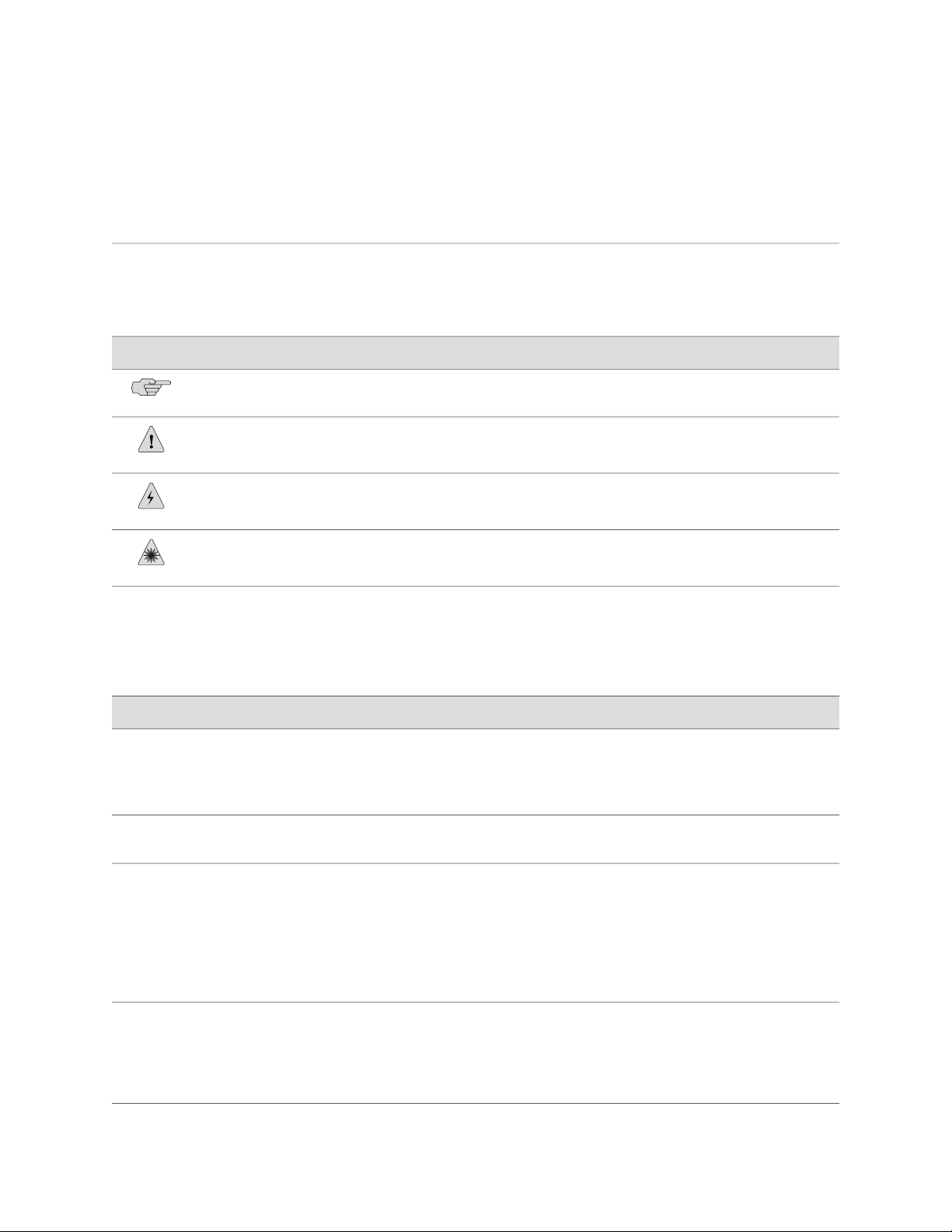
Table 2 on page xvii defines the notice icons used in this guide.
Table 2: Notice Icons
About This Guide
DescriptionMeaningIcon
Indicates important features or instructions.Informational note
Indicates a situation that might result in loss of data or hardware damage.Caution
Table 3 on page xvii defines the text and syntax conventions used in this guide.
Table 3: Text and Syntax Conventions
Bold text like this
Fixed-width text like this
Italic text like this
Alerts you to the risk of personal injury or death.Warning
Alerts you to the risk of personal injury from a laser.Laser warning
Represents text that you type.
Represents output that appears on the
terminal screen.
Introduces important new terms.
■
Identifies book names.
■
Identifies RFC and Internet draft
■
titles.
ExamplesDescriptionConvention
To enter configuration mode, type the
configure command:
user@host> configure
user@host> show chassis alarms
No alarms currently active
A policy term is a named structure
■
that defines match conditions and
actions.
JUNOS System Basics Configuration
■
Guide
RFC 1997, BGP Communities
■
Attribute
Italic text like this
Represents variables (options for which
you substitute a value) in commands or
configuration statements.
Configure the machine’s domain name:
[edit]
root@# set system domain-name
domain-name
Document Conventions ■ xvii
Page 18

J-series™ Services Router Administration Guide
Table 3: Text and Syntax Conventions (continued)
ExamplesDescriptionConvention
Plain text like this
| (pipe symbol)
# (pound sign)
[ ] (square brackets)
Indention and braces ( { } )
; (semicolon)
Represents names of configuration
statements, commands, files, and
directories; IP addresses; configuration
hierarchy levels; or labels on routing
platform components.
Enclose optional keywords or variables.< > (angle brackets)
Indicates a choice between the mutually
exclusive keywords or variables on either
side of the symbol. The set of choices is
often enclosed in parentheses for clarity.
Indicates a comment specified on the
same line as the configuration statement
to which it applies.
Enclose a variable for which you can
substitute one or more values.
Identify a level in the configuration
hierarchy.
Identifies a leaf statement at a
configuration hierarchy level.
To configure a stub area, include
■
the stub statement at the [edit
protocols ospf area area-id]
hierarchy level.
The console port is labeled
■
CONSOLE.
stub <default-metric metric>;
broadcast | multicast
(string1 | string2 | string3)
rsvp { # Required for dynamic MPLS only
community name members [
community-ids ]
[edit]
routing-options {
static {
route default {
nexthop address;
retain;
}
}
}
J-Web GUI Conventions
Bold text like this
Represents J-Web graphical user
interface (GUI) items you click or select.
> (bold right angle bracket)
Separates levels in a hierarchy of J-Web
selections.
Related Juniper Networks Documentation
J-series Services Routers are documented in multiple guides. Although the J-series
guides provide instructions for configuring and managing a Services Router with the
JUNOS CLI, they are not a comprehensive JUNOS software resource. For complete
documentation of the statements and commands described in J-series guides, see
the JUNOS software manuals listed in Table 4 on page xix.
xviii ■ Related Juniper Networks Documentation
In the Logical Interfaces box, select
■
All Interfaces.
To cancel the configuration, click
■
Cancel.
In the configuration editor hierarchy,
select Protocols>Ospf.
Page 19

Table 4: J-series Guides and Related JUNOS Software Publications
Corresponding JUNOS Software ManualChapter in a J-series Guide
Getting Started Guide for Your Router
“Services Router User Interface Overview”
“Establishing Basic Connectivity”
JUNOS CLI User Guide
■
JUNOS System Basics Configuration Guide
■
J-series Services Router Basic LAN and WAN Access Configuration Guide
“Using Services Router Configuration Tools”
JUNOS CLI User Guide
■
JUNOS System Basics Configuration Guide
■
About This Guide
“Interfaces Overview”
“Configuring DS1, DS3, Ethernet, and Serial Interfaces”
“Configuring Channelized T1/E1/ISDN PRI Interfaces”
“Configuring Digital Subscriber Line Interfaces
“Configuring Point-to-Point Protocol over Ethernet”
“Configuring ISDN”
“Configuring Link Services Interfaces”
“Configuring VoIP”
“Configuring uPIMs as Ethernet Switches”
“Routing Overview”
“Configuring Static Routes”
“Configuring a RIP Network”
JUNOS Network Interfaces Configuration Guide
■
JUNOS Interfaces Command Reference
■
JUNOS Services Interfaces Configuration Guide
■
JUNOS System Basics and Services Command Reference
■
JUNOS Network Interfaces Configuration Guide
■
JUNOS Interfaces Command Reference
■
JUNOS Network Interfaces Configuration Guide
■
JUNOS System Basics Configuration Guide
■
JUNOS System Basics and Services Command Reference
■
JUNOS Routing Protocols Configuration Guide
■
JUNOS Routing Protocols and Policies Command Reference
■
“Configuring an OSPF Network”
“Configuring the IS-IS Protocol”
“Configuring BGP Sessions”
J-series Services Router Advanced WAN Access Configuration Guide
“Multiprotocol Label Switching Overview”
“Configuring Signaling Protocols for Traffic Engineering”
JUNOS MPLS Applications Configuration Guide
■
JUNOS Routing Protocols and Policies Command Reference
■
JUNOS VPNs Configuration Guide
■
“Configuring Virtual Private Networks”
“Configuring CLNS VPNs”
Related Juniper Networks Documentation ■ xix
Page 20

J-series™ Services Router Administration Guide
Table 4: J-series Guides and Related JUNOS Software Publications (continued)
Corresponding JUNOS Software ManualChapter in a J-series Guide
“Configuring IPSec for Secure Packet Exchange”
“Multicast Overview”
“Configuring a Multicast Network”
“Configuring Data Link Switching”
“Policy Framework Overview”
“Configuring Routing Policies”
“Configuring NAT”
“Configuring Stateful Firewall Filters and NAT”
“Configuring Stateless Firewall Filters”
“Class-of-Service Overview”
“Configuring Class of Service”
JUNOS System Basics Configuration Guide
■
JUNOS Services Interfaces Configuration Guide
■
JUNOS System Basics and Services Command Reference
■
JUNOS Multicast Protocols Configuration Guide
■
JUNOS Routing Protocols and Policies Command Reference
■
JUNOS Services Interfaces Configuration Guide
■
JUNOS System Basics and Services Command Reference
■
JUNOS Policy Framework Configuration Guide
■
JUNOS Routing Protocols and Policies Command Reference
■
JUNOS Network Interfaces Configuration Guide
■
JUNOS Policy Framework Configuration Guide
■
JUNOS Services Interfaces Configuration Guide
■
Secure Configuration Guide for Common Criteria and
■
JUNOS-FIPS
JUNOS System Basics and Services Command Reference
■
JUNOS Routing Protocols and Policies Command Reference
■
JUNOS Class of Service Configuration Guide
■
JUNOS System Basics and Services Command Reference
■
J-series Services Router Administration Guide
“Managing User Authentication and Access”
“Configuring SNMP for Network Management”
“Configuring Autoinstallation”
“Monitoring the Router and Routing Operations”
“Monitoring Events and Managing System Log Files”
JUNOS System Basics Configuration Guide
■
Secure Configuration Guide for Common Criteria and
■
JUNOS-FIPS
JUNOS Network Management Configuration Guide“Setting Up USB Modems for Remote Management”
JUNOS System Basics Configuration Guide“Configuring the Router as a DHCP Server”
JUNOS Configuration and Diagnostic Automation Guide“Automating Network Operations and Troubleshooting”
JUNOS System Basics and Services Command Reference
■
JUNOS Interfaces Command Reference
■
JUNOS Routing Protocols and Policies Command Reference
■
JUNOS System Log Messages Reference
■
Secure Configuration Guide for Common Criteria and
■
JUNOS-FIPS
xx ■ Related Juniper Networks Documentation
Page 21

Table 4: J-series Guides and Related JUNOS Software Publications (continued)
Corresponding JUNOS Software ManualChapter in a J-series Guide
JUNOS System Basics Configuration Guide“Configuring and Monitoring Alarms”
JUNOS Software Installation and Upgrade Guide“Performing Software Upgrades and Reboots”
JUNOS System Basics Configuration Guide“Managing Files”
About This Guide
“Using Services Router Diagnostic Tools”
Documentation Feedback
We encourage you to provide feedback, comments, and suggestions so that we can
improve the documentation. You can send your comments to
techpubs-comments@juniper.net, or fill out the documentation feedback form at
http://www.juniper.net/techpubs/docbug/docbugreport.html. If you are using e-mail, be sure
to include the following information with your comments:
■ Document name
■ Document part number
■ Page number
■ Software release version (not required for Network Operations Guides [NOGs])
Requesting Technical Support
JUNOS System Basics and Services Command Reference
■
JUNOS Interfaces Command Reference
■
JUNOS Routing Protocols and Policies Command Reference
■
JUNOS Services Interfaces Configuration Guide“Configuring Packet Capture”
JUNOS System Basics and Services Command Reference“Configuring RPM Probes”
Technical product support is available through the Juniper Networks Technical
Assistance Center (JTAC). If you are a customer with an active J-Care or JNASC support
contract, or are covered under warranty, and need postsales technical support, you
can access our tools and resources online or open a case with JTAC.
■ JTAC policies—For a complete understanding of our JTAC procedures and policies,
review the JTAC User Guide located at
http://www.juniper.net/customers/support/downloads/710059.pdf.
■ Product warranties—For product warranty information, visit
http://www.juniper.net/support/warranty/.
■ JTAC Hours of Operation —The JTAC centers have resources available 24 hours
a day, 7 days a week, 365 days a year.
Self-Help Online Tools and Resources
Documentation Feedback ■ xxi
Page 22

J-series™ Services Router Administration Guide
For quick and easy problem resolution, Juniper Networks has designed an online
self-service portal called the Customer Support Center (CSC) that provides you with
the following features:
■
Find CSC offerings: http://www.juniper.net/customers/support/
■
Search for known bugs: http://www2.juniper.net/kb/
■
Find product documentation: http://www.juniper.net/techpubs/
■ Find solutions and answer questions using our Knowledge Base:
http://kb.juniper.net/
■ Download the latest versions of software and review release notes:
http://www.juniper.net/customers/csc/software/
■ Search technical bulletins for relevant hardware and software notifications:
https://www.juniper.net/alerts/
■ Join and participate in the Juniper Networks Community Forum:
http://www.juniper.net/company/communities/
■
Open a case online in the CSC Case Manager: http://www.juniper.net/cm/
To verify service entitlement by product serial number, use our Serial Number
Entitlement (SNE) Tool located at https://tools.juniper.net/SerialNumberEntitlementSearch/.
Opening a Case with JTAC
You can open a case with JTAC on the Web or by telephone.
■
Use the Case Manager tool in the CSC at http://www.juniper.net/cm/ .
■ Call 1-888-314-JTAC (1-888-314-5822 toll-free in the USA, Canada, and Mexico).
For international or direct-dial options in countries without toll-free numbers, visit
us at http://www.juniper.net/support/requesting-support.html.
xxii ■ Requesting Technical Support
Page 23

Part 1
Configuring a Services Router for Administration
■ Managing User Authentication and Access on page 3
■ Setting Up USB Modems for Remote Management on page 29
■ Configuring SNMP for Network Management on page 47
■ Configuring the Router as a DHCP Server on page 63
■ Configuring Autoinstallation on page 81
■ Automating Network Operations and Troubleshooting on page 89
Configuring a Services Router for Administration ■ 1
Page 24

J-series™ Services Router Administration Guide
2 ■ Configuring a Services Router for Administration
Page 25

Chapter 1
Managing User Authentication and Access
You can use either J-Web Quick Configuration or a configuration editor to manage
system functions, including RADIUS and TACACS+ servers, and user login accounts.
This chapter contains the following topics. For more information about system
management, see the JUNOS System Basics Configuration Guide.
If the router is operating in a Common Criteria environment, see the Secure
Configuration Guide for Common Criteria and JUNOS-FIPS.
■ User Authentication Terms on page 3
■ User Authentication Overview on page 4
■ Before You Begin on page 8
■ Managing User Authentication with Quick Configuration on page 8
■ Managing User Authentication with a Configuration Editor on page 12
■ Recovering the Root Password on page 21
■ Securing the Console Port on page 23
■ Accessing Remote Devices with the CLI on page 24
■ Configuring Password Retry Limits for Telnet and SSH Access on page 26
User Authentication Terms
Before performing system management tasks, become familiar with the terms defined
in Table 5 on page 3.
Table 5: System Management Terms
Remote Authentication Dial-In User
Service (RADIUS)
Terminal Access Controller Access
Control System Plus (TACACS+)
DefinitionTerm
Authentication method for validating users who attempt to access one or more
Services Routers by means of Telnet. RADIUS is a multivendor IETF standard
whose features are more widely accepted than those of TACACS+ or other
proprietary systems. All one-time-password system vendors support RADIUS.
Authentication method for validating users who attempt to access one or more
Services Routers by means of Telnet.
User Authentication Terms ■ 3
Page 26

J-series™ Services Router Administration Guide
User Authentication Overview
This section contains the following topics:
■ User Authentication on page 4
■ User Accounts on page 4
■ Login Classes on page 5
■ Template Accounts on page 7
User Authentication
The JUNOS software supports three methods of user authentication: local password
authentication, Remote Authentication Dial-In User Service (RADIUS), and Terminal
Access Controller Access Control System Plus (TACACS+).
With local password authentication, you configure a password for each user allowed
to log into the Services Router.
User Accounts
RADIUS and TACACS+ are authentication methods for validating users who attempt
to access the router using Telnet. Both are distributed client/server systems—the
RADIUS and TACACS+ clients run on the router, and the server runs on a remote
network system.
You can configure the router to use RADIUS or TACACS+ authentication, or both,
to validate users who attempt to access the router. If you set up both authentication
methods, you also can configure which the router will try first.
User accounts provide one way for users to access the Services Router. Users can
access the router without accounts if you configured RADIUS or TACACS+ servers,
as described in “Managing User Authentication with Quick Configuration” on page
8 and “Managing User Authentication with a Configuration Editor” on page 12.
After you have created an account, the router creates a home directory for the user.
An account for the user root is always present in the configuration. For information
about configuring the password for the user root, see the Getting Started Guide for
your router. For each user account, you can define the following:
■ Username—Name that identifies the user. It must be unique within the router.
Do not include spaces, colons, or commas in the username.
■ User's full name—If the full name contains spaces, enclose it in quotation marks
(“ ”). Do not include colons or commas.
■ User identifier (UID)—Numeric identifier that is associated with the user account
name. The identifier must be in the range 100 through 64000 and must be unique
within the router. If you do not assign a UID to a username, the software assigns
one when you commit the configuration, preferring the lowest available number.
■ User's access privilege—You can create login classes with specific permission
bits or use one of the default classes listed in Table 6 on page 5.
■ Authentication method or methods and passwords that the user can use to access
the router—You can use SSH or an MD5 password, or you can enter a plain-text
4 ■ User Authentication Overview
Page 27

Login Classes
Chapter 1: Managing User Authentication and Access
password that the JUNOS software encrypts using MD5-style encryption before
entering it in the password database. If you configure the plain-text-password
option, you are prompted to enter and confirm the password.
All users who log into the Services Router must be in a login class. You can define
any number of login classes. With login classes, you define the following:
■ Access privileges users have when they are logged into the router. For more
information, see “Permission Bits” on page 5.
■ Commands and statements that users can and cannot specify. For more
information, see “Denying or Allowing Individual Commands” on page 7.
■ How long a login session can be idle before it times out and the user is logged
off.
You then apply one login class to an individual user account. The software contains
a few predefined login classes, which are listed in Table 6 on page 5. The predefined
login classes cannot be modified.
Table 6: Predefined Login Classes
unauthorized
Permission Bits
Each top-level command-line interface (CLI) command and each configuration
statement has an access privilege level associated with it. Users can execute only
those commands and configure and view only those statements for which they have
access privileges. The access privileges for each login class are defined by one or
more permission bits (see Table 7 on page 6).
Permission Bits SetLogin Class
clear, network, reset, trace, viewoperator
viewread-only
allsuper-user and superuser
None
Two forms for the permissions control the individual parts of the configuration:
■ "Plain" form—Provides read-only capability for that permission type. An example
is interface.
■
Form that ends in -control—Provides read and write capability for that permission
type. An example is interface-control.
User Authentication Overview ■ 5
Page 28

J-series™ Services Router Administration Guide
Table 7: Permission Bits for Login Classes
AccessPermission Bit
admin
access
all
clear
configure
control
field
firewall
floppy
Can view user account information in configuration mode and with the show configuration
command.
Can view user accounts and configure them (at the [edit system login] hierarchy level).admin-control
Can view the access configuration in configuration mode and with the show configuration
operational mode command.
Can view and configure access information (at the [edit access] hierarchy level).access-control
Has all permissions.
Can clear (delete) information learned from the network that is stored in various network
databases (using the clear commands).
Can enter configuration mode (using the configure command) and commit configurations
(using the commit command).
Can perform all control-level operations (all operations configured with the -control
permission bits).
Reserved for field (debugging) support.
Can view the firewall filter configuration in configuration mode.
Can view and configure firewall filter information (at the [edit firewall] hierarchy level).firewall-control
Can read from and write to the removable media.
interface
interface-control
maintenance
reset
rollback
routing
Can view the interface configuration in configuration mode and with the show
configuration operational mode command.
Can view chassis, class of service, groups, forwarding options, and interfaces
configuration information. Can configure chassis, class of service, groups, forwarding
options, and interfaces (at the [edit] hierarchy).
Can perform system maintenance, including starting a local shell on the router and
becoming the superuser in the shell (by issuing the su root command), and can halt and
reboot the router (using the request system commands).
Can access the network by entering the ping, ssh, telnet, and traceroute commands.network
Can restart software processes using the restart command and can configure whether
software processes are enabled or disabled (at the [edit system processes] hierarchy
level).
Can use the rollback command to return to a previously committed configuration other
than the most recently committed one.
Can view general routing, routing protocol, and routing policy configuration information
in configuration and operational modes.
6 ■ User Authentication Overview
Page 29

Table 7: Permission Bits for Login Classes (continued)
AccessPermission Bit
Chapter 1: Managing User Authentication and Access
routing-control
secret
secret-control
security
snmp
snmp-control
system
system-control
trace
Can view general routing, routing protocol, and routing policy configuration information
and configure general routing (at the [edit routing-options] hierarchy level), routing
protocols (at the [edit protocols] hierarchy level), and routing policy (at the [edit
policy-options] hierarchy level).
Can view passwords and other authentication keys in the configuration.
Can view passwords and other authentication keys in the configuration and can modify
them in configuration mode.
Can view security configuration in configuration mode and with the show configuration
operational mode command.
Can view and configure security information (at the [edit security] hierarchy level).security-control
Can start a local shell on the router by entering the start shell command.shell
Can view SNMP configuration information in configuration and operational modes.
Can view SNMP configuration information and configure SNMP (at the [edit snmp]
hierarchy level).
Can view system-level information in configuration and operational modes.
Can view system-level configuration information and configure it (at the [edit system]
hierarchy level).
Can view trace file settings in configuration and operational modes.
trace-control
view
Template Accounts
Can view trace file settings and configure trace file properties.
Can use various commands to display current systemwide, routing table, and
protocol-specific values and statistics.
Denying or Allowing Individual Commands
By default, all top-level CLI commands have associated access privilege levels. Users
can execute only those commands and view only those statements for which they
have access privileges. For each login class, you can explicitly deny or allow the use
of operational and configuration mode commands that are otherwise permitted or
not allowed by a permission bit.
You use local user template accounts when you need different types of templates.
Each template can define a different set of permissions appropriate for the group of
users who use that template. These templates are defined locally on the Services
Router and referenced by the TACACS+ and RADIUS authentication servers.
User Authentication Overview ■ 7
Page 30

J-series™ Services Router Administration Guide
When you configure local user templates and a user logs in, the JUNOS software
issues a request to the authentication server to authenticate the user's login name.
If a user is authenticated, the server returns the local username to the router, which
then determines whether a local username is specified for that login name
(local-username for TACACS+, Juniper-Local-User for RADIUS). If so, the router selects
the appropriate local user template locally configured on the router. If a local user
template does not exist for the authenticated user, the router defaults to the remote
template.
For more information, see “Setting Up Template Accounts” on page 18.
Before You Begin
Before you perform any system management tasks, you must perform the initial
Services Router configuration described in the Getting Started Guide for your router.
Managing User Authentication with Quick Configuration
This section contains the following topics:
■ Adding a RADIUS Server for Authentication on page 8
■ Adding a TACACS+ Server for Authentication on page 9
■ Configuring System Authentication on page 10
■ Adding New Users on page 11
Adding a RADIUS Server for Authentication
You can use the Users Quick Configuration page for RADIUS servers to configure a
RADIUS server for system authentication. This Quick Configuration page allows you
to specify the IP address and secret (password) of the RADIUS server.
Figure 1 on page 8 shows the Users Quick Configuration page for RADIUS servers.
Figure 1: Users Quick Configuration Page for RADIUS Servers
ERROR: Unresolved graphic fileref="s020241.gif" not found in
"\\teamsite1\default\main\TechPubsWorkInProgress\STAGING\images\".
To configure a RADIUS server with Quick Configuration:
1. In the J-Web interface, select Configuration>Quick Configuration>Users.
2. Under RADIUS servers, click Add to configure a RADIUS server.
8 ■ Before You Begin
3. Enter information into the Users Quick Configuration page for RADIUS servers,
as described in Table 8 on page 9.
4. Click one of the following buttons on the Users Quick Configuration page for
RADIUS servers:
■ To apply the configuration and return to the Users Quick Configuration page,
click OK.
Page 31

■ To cancel your entries and return to the Users Quick Configuration page,
click Cancel.
Table 8: Users Quick Configuration for RADIUS Servers Summary
RADIUS Server
RADIUS Server Address
(required)
Identifies the IP address of the RADIUS
server.
Chapter 1: Managing User Authentication and Access
Your ActionFunctionField
Type the RADIUS server’s 32-bit IP address, in
dotted decimal notation.
RADIUS Server Secret (required)
Verify RADIUS Server Secret
(required)
The secret (password) of the RADIUS
server.
RADIUS server is entered correctly.
Adding a TACACS+ Server for Authentication
You can use the Users Quick Configuration page for TACACS+ servers to configure
a TACACS+ server for system authentication. This Quick Configuration page allows
you to specify the IP address and secret of the TACACS+ server.
Figure 2 on page 9 shows the Users Quick Configuration page for TACACS+ servers.
Figure 2: Users Quick Configuration Page for TACACS+ Servers
ERROR: Unresolved graphic fileref="s020242.gif" not found in
"\\teamsite1\default\main\TechPubsWorkInProgress\STAGING\images\".
To configure a TACACS+ server with Quick Configuration:
1. In the J-Web interface, select Configuration>Quick Configuration>Users.
2. Under TACACS+ servers, click Add to configure a TACACS+ server.
Type the secret (password) of the RADIUS server.
Secrets can contain spaces. The secret used must
match that used by the RADIUS server.
Retype the secret of the RADIUS server.Verifies the secret (password) of the
3. Enter information into the Users Quick Configuration page for TACACS+ servers,
as described in Table 9 on page 10.
4. Click one of the following buttons on the Users Quick Configuration page for
TACACS+ servers:
■ To apply the configuration and return to the Users Quick Configuration page,
click OK.
■ To cancel your entries and return to the Users Quick Configuration page,
click Cancel.
Managing User Authentication with Quick Configuration ■ 9
Page 32

J-series™ Services Router Administration Guide
Table 9: Users Quick Configuration for TACACS+ Servers Summary
TACACS+ Server
TACACS+ Server Address
(required)
Identifies the IP address of the
TACACS+ server.
Your ActionFunctionField
Type the TACACS+ server’s 32-bit IP address, in
dotted decimal notation.
TACACS+ Server Secret
(required)
Verify TACACS+ Server Secret
(required)
The secret (password) of the TACACS+
server.
TACACS+ server is entered correctly.
Configuring System Authentication
On the Users Quick Configuration page, you can configure the authentication methods
the Services Router uses to verify that a user can gain access. For each login attempt,
the router tries the authentication methods in order, starting with the first one, until
the password matches.
If you do not configure system authentication, users are verified based on their
configured local passwords.
Figure 3 on page 10 shows the Users Quick Configuration page.
Figure 3: Users Quick Configuration Page
"\\teamsite1\default\main\TechPubsWorkInProgress\STAGING\images\".
Type the secret (password) of the TACACS+
server. Secrets can contain spaces. The secret
used must match that used by the TACACS+
server.
Retype the secret of the TACACS+ server.Verifies the secret (password) of the
ERROR: Unresolved graphic fileref="s020243.gif" not found in
To configure system authentication with Quick Configuration:
1. In the J-Web interface, select Configuration>Quick Configuration>Users.
2. Under Authentication Servers, select the check box next to each authentication
method the router must use when users log in:
■ RADIUS
■ TACACS+
■ Local Password
3. Click one of the following buttons on the Users Quick Configuration page:
■ To apply the configuration and stay in the Users Quick Configuration page,
click Apply.
■ To apply the configuration and return to the Quick Configuration page, click
OK.
■ To cancel your entries and return to the Quick Configuration page, click
Cancel.
10 ■ Managing User Authentication with Quick Configuration
Page 33

Adding New Users
Chapter 1: Managing User Authentication and Access
You can use the Users Quick Configuration page for user information to add new
users to a Services Router. For each account, you define a login name and password
for the user and specify a login class for access privileges.
Figure 4 on page 11 shows the Quick Configuration page for adding a user.
Figure 4: Add a User Quick Configuration Page
ERROR: Unresolved graphic fileref="s020244.gif" not found in
"\\teamsite1\default\main\TechPubsWorkInProgress\STAGING\images\".
To configure users with Quick Configuration:
1. In the J-Web interface, select Configuration>Quick Configuration>Users.
2. Under Users, click Add to add a new user.
3. Enter information into the Add a User Quick Configuration page, as described
in Table 10 on page 11.
4. Click one of the following buttons on the Add a User Quick Configuration page:
■ To apply the configuration and return to the Users Quick Configuration page,
click OK.
■ To cancel your entries and return to the Users Quick Configuration page,
click Cancel.
Table 10: Add a User Quick Configuration Page Summary
Your ActionFunctionField
User Information
Type the username. It must be unique within the router. Do not
include spaces, colons, or commas in the username.
Type the user's full name. If the full name contains spaces, enclose
it in quotation marks. Do not include colons or commas.
From the list, select the user's login class:
operator
■
read-only
■
super-user/superuser
■
unauthorized
■
Login Class (required)
Name that identifies the user.Username (required)
The user's full name.Full Name
Defines the user's access
privilege.
This list also includes any user-defined login classes. For more
information, see “Login Classes” on page 5.
Managing User Authentication with Quick Configuration ■ 11
Page 34

J-series™ Services Router Administration Guide
Table 10: Add a User Quick Configuration Page Summary (continued)
Your ActionFunctionField
Login Password
(required)
Verify Login Password
(required)
The login password for this
user.
for this user.
Type the login password for this user. The login password must
meet the following criteria:
The password must be at least 6 characters long.
■
You can include most character classes in a password
■
(alphabetic, numeric, and special characters), except control
characters.
The password must contain at least one change of case or
■
character class.
Retype the login password for this user.Verifies the login password
Managing User Authentication with a Configuration Editor
This section contains the following topics:
■ Setting Up RADIUS Authentication on page 12
■ Setting Up TACACS+ Authentication on page 13
■ Configuring Authentication Order on page 15
■ Controlling User Access on page 16
■ Setting Up Template Accounts on page 18
Setting Up RADIUS Authentication
To use RADIUS authentication, you must configure at least one RADIUS server.
The procedure provided in this section identifies the RADIUS server, specifies the
secret (password) of the RADIUS server, and sets the source address of the Services
Router's RADIUS requests to the loopback address of the router. The procedure uses
the following sample values:
■
The RADIUS server's IP address is 172.16.98.1.
■
The RADIUS server's secret is Radiussecret1.
■
The loopback address of the router is 10.0.0.1.
To configure RADIUS authentication:
1. Navigate to the top of the configuration hierarchy in either the J-Web or CLI
configuration editor.
2. Perform the configuration tasks described in Table 11 on page 13.
3. If you are finished configuring the network, commit the configuration.
To completely set up RADIUS authentication, you must create user template
accounts and specify a system authentication order.
12 ■ Managing User Authentication with a Configuration Editor
Page 35

4. Go on to one of the following procedures:
■ To specify a system authentication order, see “Configuring Authentication
Order” on page 15.
■ To configure a remote user template account, see “Creating a Remote
Template Account” on page 19.
■ To configure local user template accounts, see “Creating a Local Template
Account” on page 20.
Table 11: Setting Up RADIUS Authentication
Chapter 1: Managing User Authentication and Access
CLI Configuration EditorJ-Web Configuration EditorTask
Navigate to the System level in the
configuration hierarchy.
Add a new RADIUS server
Specify the shared secret (password) of
the RADIUS server. The secret is stored
as an encrypted value in the
configuration database.
Specify the source address to be
included in the RADIUS server requests
by the router. In most cases, you can
use the loopback address of the router.
In the J-Web interface, select
1.
Configuration>View and Edit>Edit
Configuration.
Next to System, click Configure or
2.
Edit.
In the Radius server box, click Add
1.
new entry.
In the Address box, type the IP
2.
address of the RADIUS server:
172.16.98.1
In the Secret box, type the shared secret of
the RADIUS server:
Radiussecret1
In the Source address box, type the
loopback address of the router:
10.0.0.1
From the [edit] hierarchy level, enter
edit system
Set the IP address of the RADIUS
server:
set radius-server address 172.16.98.1
Set the shared secret of the RADIUS
server:
set radius-server 172.16.98.1 secret
Radiussecret1
Set the router's loopback address as
the source address:
set radius-server 172.16.98.1
source-address 10.0.0.1
Setting Up TACACS+ Authentication
To use TACACS+ authentication, you must configure at least one TACACS+ server.
The procedure provided in this section identifies the TACACS+ server, specifies the
secret (password) of the TACACS+ server, and sets the source address of the Services
Router's TACACS+ requests to the loopback address of the router. This procedure
uses the following sample values:
■
The TACACS+ server's IP address is 172.16.98.24.
■
The TACACS+ server's secret is Tacacssecret1.
■
The loopback address of the router is 10.0.0.1.
Managing User Authentication with a Configuration Editor ■ 13
Page 36

J-series™ Services Router Administration Guide
To configure TACACS+ authentication:
1. Navigate to the top of the configuration hierarchy in either the J-Web or CLI
configuration editor.
2. Perform the configuration tasks described in Table 12 on page 14.
3. If you are finished configuring the network, commit the configuration.
To completely set up TACACS+ authentication, you must create user template
accounts and specify a system authentication order.
4. Go on to one of the following procedures:
■ To specify a system authentication order, see “Configuring Authentication
Order” on page 15.
■ To configure a remote user template account, see “Creating a Remote
Template Account” on page 19.
■ To configure local user template accounts, see “Creating a Local Template
Account” on page 20.
Table 12: Setting Up TACACS+ Authentication
Navigate to the System level in the
configuration hierarchy.
Add a new TACACS+ server
Specify the shared secret (password) of
the TACACS+ server. The secret is
stored as an encrypted value in the
configuration database.
Specify the source address to be
included in the TACACS+ server
requests by the router. In most cases,
you can use the loopback address of the
router.
In the J-Web interface, select
1.
Configuration>View and Edit>Edit
Configuration.
Next to System, click Configure or
2.
Edit.
In the Tacplus server box, click Add
1.
new entry.
In the Address box, type the IP
2.
address of the TACACS+ server:
172.16.98.24
In the Secret box, type the shared secret of
the TACACS+ server:
Tacacssecret1
In the Source address box, type the
loopback address of the router:
10.0.0.1
CLI Configuration EditorJ-Web Configuration EditorTask
From the [edit] hierarchy level, enter
edit system
Set the IP address of the TACACS+
server:
set tacplus-server address
172.16.98.24
Set the shared secret of the TACACS+
server:
set tacplus-server 172.16.98.24 secret
Tacacssecret1
Set the router's loopback address as
the source address:
set tacplus-server 172.16.98.24
source-address 10.0.0.1
14 ■ Managing User Authentication with a Configuration Editor
Page 37

Configuring Authentication Order
The procedure provided in this section configures the Services Router to attempt
user authentication with the local password first, then with the RADIUS server, and
finally with the TACACS+ server.
To configure authentication order:
1. Navigate to the top of the configuration hierarchy in either the J-Web or CLI
configuration editor.
2. Perform the configuration tasks described in Table 13 on page 15.
3. If you are finished configuring the network, commit the configuration.
To completely set up RADIUS or TACACS+ authentication, you must configure
at least one RADIUS or TACACS+ server and create user template accounts.
4. Go on to one of the following procedures:
■ To configure a RADIUS server, see “Setting Up RADIUS
Authentication” on page 12.
Chapter 1: Managing User Authentication and Access
■ To configure a TACACS+ server, see “Setting Up TACACS+
Authentication” on page 13.
■ To configure a remote user template account, see “Creating a Remote
Template Account” on page 19.
■ To configure local user template accounts, see “Creating a Local Template
Account” on page 20.
Table 13: Configuring Authentication Order
Navigate to the System level in
the configuration hierarchy.
Add RADIUS authentication to
the authentication order.
Add TACACS+ authentication to
the authentication order.
In the J-Web interface, select
1.
Configuration>View and Edit>Edit
Configuration.
Next to System, click Configure or Edit.
2.
In the Authentication order box, click Add
1.
new entry.
In the list, select radius.
2.
Click OK.
3.
In the Authentication Order box, click Add
1.
new entry.
In the list, select tacplus.
2.
Click OK.
3.
CLI Configuration EditorJ-Web Configuration EditorTask
From the [edit] hierarchy level, enter
edit system
Insert the radius statement in the
authentication order:
insert system authentication-order radius
after password
Insert the tacplus statement in the
authentication order:
insert system authentication-order tacplus
after radius
Managing User Authentication with a Configuration Editor ■ 15
Page 38

J-series™ Services Router Administration Guide
Controlling User Access
This section contains the following topics:
■ Defining Login Classes on page 16
■ Creating User Accounts on page 17
Defining Login Classes
You can define any number of login classes. You then apply one login class to an
individual user account, as described in “Creating User Accounts” on page 17 and
“Setting Up Template Accounts” on page 18.
The procedure provided in this section creates a sample login class named
operator-and-boot with the following privileges:
■
The operator-and-boot login class can reboot the Services Router using the request
system reboot command.
■
The operator-and-boot login class can also use commands defined in the clear,
network, reset, trace, and view permission bits. For more information, see
“Permission Bits” on page 5.
To define login classes:
1. Navigate to the top of the configuration hierarchy in either the J-Web or CLI
configuration editor.
2. Perform the configuration tasks described in Table 14 on page 16.
3. If you are finished configuring the network, commit the configuration.
4. Go on to one of the following procedures:
■ To create user accounts, see “Creating User Accounts” on page 17.
■ To create shared user accounts, see “Setting Up Template
Table 14: Defining Login Classes
Navigate to the System
Login level in the
configuration hierarchy.
In the J-Web interface, select Configuration>View
1.
and Edit>Edit Configuration.
Next to System, click Configure or Edit.
2.
Next to Login, click Configure or Edit.
3.
Accounts” on page 18.
CLI Configuration EditorJ-Web Configuration EditorTask
From the [edit] hierarchy level,
enter
edit system login
16 ■ Managing User Authentication with a Configuration Editor
Page 39

Table 14: Defining Login Classes (continued)
Chapter 1: Managing User Authentication and Access
CLI Configuration EditorJ-Web Configuration EditorTask
Create a login class named
operator-and-boot with the
ability to reboot the router.
Give the operator-and-boot
login class operator
privileges.
Next to Class, click Add new entry.
1.
Type the name of the login class:
2.
operator-and-boot
In the Allow commands box, type the request system
3.
reboot command enclosed in quotation marks:
“request system reboot”
Click OK.
4.
Next to Permissions, click Add new entry.
1.
In the Value list, select clear.
2.
Click OK.
3.
Next to Permissions, click Add new entry.
4.
In the Value list, select network.
5.
Click OK.
6.
Next to Permissions, click Add new entry.
7.
In the Value list, select reset.
8.
Click OK.
9.
Next to Permissions, click Add new entry.
10.
In the Value list, select trace.
11.
Click OK.
12.
Next to Permissions, click Add new entry.
13.
In the Value list, select view.
14.
Click OK.
15.
Set the name of the login class and
the ability to use the request system
reboot command:
set class operator-and-boot
allow-commands “request system
reboot”
Set the permission bits for the
operator-and-boot login class:
set class operator-and-boot
permissions [clear network reset
trace view]
Creating User Accounts
User accounts provide one way for users to access the Services Router. (Users can
access the router without accounts if you configured RADIUS or TACACS+ servers,
as described in “Setting Up RADIUS Authentication” on page 12 and “Setting Up
TACACS+ Authentication” on page 13.)
The procedure provided in this section creates a sample user named cmartin with
the following characteristics:
■
The user cmartin belongs to the superuser login class.
■
The user cmartin uses an encrypted password, $1$14c5.$sBopasdFFdssdfFFdsdfs0.
Managing User Authentication with a Configuration Editor ■ 17
Page 40

J-series™ Services Router Administration Guide
To create user accounts:
1. Navigate to the top of the configuration hierarchy in either the J-Web or CLI
configuration editor.
2. Perform the configuration tasks described in Table 15 on page 18.
3. If you are finished configuring the network, commit the configuration.
Table 15: Creating User Accounts
CLI Configuration EditorJ-Web Configuration EditorTask
Navigate to the System Login level in
the configuration hierarchy.
Create a user named cmartin who
belongs to the superuser login class.
Define the encrypted password for
cmartin.
In the J-Web interface, select
1.
Configuration>View and
Edit>Edit Configuration.
Next to System, click Configure or
2.
Edit.
Next to Login, click Configure or
3.
Edit.
Next to User, click Add new entry.
1.
In the User name box, type cmartin.
2.
In the Class box, type superuser.
3.
Click OK.
4.
Next to Authentication, click
1.
Configure.
In the Encrypted password box,
2.
type
$1$14c5.$sBopasdFFdssdfFFdsdfs0
Click OK.
3.
From the [edit] hierarchy level, enter
edit system login
Set the username and the login class for
the user:
set user cmartin class superuser
Set the encrypted password for cmartin.
set user cmartin authentication
encrypted-password
$1$14c5.$sBopasdFFdssdfFFdsdfs0
Setting Up Template Accounts
You can create template accounts that are shared by a set of users when you are
using RADIUS or TACACS+ authentication. When a user is authenticated by a
template account, the CLI username is the login name, and the privileges, file
ownership, and effective user ID are inherited from the template account.
This section contains the following topics:
■ Creating a Remote Template Account on page 19
■ Creating a Local Template Account on page 20
18 ■ Managing User Authentication with a Configuration Editor
Page 41

Chapter 1: Managing User Authentication and Access
Creating a Remote Template Account
You can create a remote template that is applied to users authenticated by RADIUS
or TACACS+ that do not belong to a local template account.
By default, the JUNOS software uses the remote template account when
■ The authenticated user does not exist locally on the Services Router.
■ The authenticated user's record in the RADIUS or TACACS+ server specifies
local user, or the specified local user does not exist locally on the router.
The procedure provided in this section creates a sample user named remote that
belongs to the operator login class.
To create a remote template account:
1. Navigate to the top of the configuration hierarchy in either the J-Web or CLI
configuration editor.
2. Perform the configuration tasks described in Table 16 on page 19.
3. If you are finished configuring the network, commit the configuration.
To completely set up RADIUS or TACACS+ authentication, you must configure
at least one RADIUS or TACACS+ server and specify a system authentication
order.
4. Go on to one of the following procedures:
■ To configure a RADIUS server, see “Setting Up RADIUS
Authentication” on page 12.
■ To configure a TACACS+ server, see “Setting Up TACACS+
Authentication” on page 13.
■ To specify a system authentication order, see “Configuring Authentication
Order” on page 15.
Table 16: Creating a Remote Template Account
Navigate to the System Login
level in the configuration
hierarchy.
In the J-Web interface, select
1.
Configuration>View and Edit>Edit
Configuration.
Next to System, click Configure or Edit.
2.
Next to Login, click Configure or Edit.
3.
CLI Configuration EditorJ-Web Configuration EditorTask
From the [edit] hierarchy level,
enter
edit system login
Create a user named remote who
belongs to the operator login class.
Next to User, click Add new entry.
1.
In the User name box, type remote.
2.
In the Class box, type operator.
3.
Click OK.
4.
Managing User Authentication with a Configuration Editor ■ 19
Set the username and the login
class for the user:
set user remote class operator
Page 42

J-series™ Services Router Administration Guide
Creating a Local Template Account
You can create a local template that is applied to users authenticated by RADIUS or
TACACS+ that are assigned to the local template account. You use local template
accounts when you need different types of templates. Each template can define a
different set of permissions appropriate for the group of users who use that template.
The procedure provided in this section creates a sample user named admin that
belongs to the superuser login class.
To create a local template account:
1. Navigate to the top of the configuration hierarchy in either the J-Web or CLI
configuration editor.
2. Perform the configuration tasks described in Table 17 on page 20.
3. If you are finished configuring the network, commit the configuration.
To completely set up RADIUS or TACACS+ authentication, you must configure
at least one RADIUS or TACACS+ server and specify a system authentication
order
4. Go on to one of the following procedures:
■ To configure a RADIUS server, see “Setting Up RADIUS
Authentication” on page 12.
■ To configure a TACACS+ server, see “Setting Up TACACS+
Authentication” on page 13.
■ To configure a system authentication order, see “Configuring Authentication
Order” on page 15.
Table 17: Creating a Local Template Account
Navigate to the System Login
level in the configuration
hierarchy.
Create a user named admin who
belongs to the superuser login
class.
In the J-Web interface, select
1.
Configuration>View and Edit>Edit
Configuration.
Next to System, click Configure or Edit.
2.
Next to Login, click Configure or Edit.
3.
Next to User, click Add new entry.
1.
In the User name box, type admin.
2.
In the Class box, type superuser.
3.
Click OK.
4.
CLI Configuration EditorJ-Web Configuration EditorTask
From the [edit] hierarchy level,
enter
edit system login
Set the username and the login
class for the user:
set user admin class superuser
20 ■ Managing User Authentication with a Configuration Editor
Page 43

Recovering the Root Password
If you forget the root password for the router, you can use the password recovery
procedure to reset the root password.
NOTE: You need console access to recover the root password.
To recover the root password:
1. Power off the router by pressing the power button on the front panel.
2. Turn off the power to the management device, such as a PC or laptop computer,
that you want to use to access the CLI.
3. Plug one end of the Ethernet rollover cable supplied with the router into the
RJ-45 to DB-9 serial port adapter supplied with the router (see Figure 5 on page
21 and Figure 6 on page 22).
Chapter 1: Managing User Authentication and Access
4. Plug the RJ-45 to DB-9 serial port adapter into the serial port on the management
device (see Figure 5 on page 21 and Figure 6 on page 22).
5. Connect the other end of the Ethernet rollover cable to the console port on the
router (see Figure 5 on page 21 and Figure 6 on page 22).
Figure 5: Connecting to the Console Port on the J2300 Services Router
Recovering the Root Password ■ 21
Page 44

J-series™ Services Router Administration Guide
Figure 6: Connecting to the Console Port on the J4350 or J6350 Services Router
6. Turn on the power to the management device.
7. On the management device, start your asynchronous terminal emulation
application (such as Microsoft Windows Hyperterminal) and select the appropriate
COM port to use (for example, COM1).
8. Configure the port settings as follows:
■ Bits per second: 9600
■ Data bits: 8
■ Parity: None
■ Stop bits: 1
■ Flow control: None
9. Power on the router by pressing the power button on the front panel. Verify that
the POWER LED on the front panel turns green.
The terminal emulation screen on your management device displays the router's
boot sequence.
10. When the following prompt appears, press the Spacebar to access the router's
bootstrap loader command prompt:
Hit [Enter] to boot immediately, or space bar for command prompt.
Booting [kernel] in 9 seconds...
11.
At the following prompt, enter boot -s to start up the system in single-user mode.
22 ■ Recovering the Root Password
ok boot -s
Page 45

Chapter 1: Managing User Authentication and Access
12.
At the following prompt, enter recovery to start the root password recovery
procedure.
Enter full pathname of shell or 'recovery' for root password recovery or
RETURN for /bin/sh: recovery
13. Enter configuration mode in the CLI.
14. Set the root password. For example:
user@host# set system root-authentication plain-text-password
For more information about configuring the root password, see the JUNOS System
Basics Configuration Guide.
15. At the following prompt, enter the new root password. For example:
New password: juniper1
Retype new password:
16. At the second prompt, reenter the new root password.
17. If you are finished configuring the network, commit the configuration.
root@host# commit
commit complete
18. Exit configuration mode in the CLI.
19. Exit operational mode in the CLI.
20.
At the prompt, enter y to reboot the router.
Reboot the system? [y/n] y
Securing the Console Port
You can use the console port on the Services Router to connect to the Routing Engine
through an RJ-45 serial cable. From the console port, you can use the CLI to configure
the router. By default, the console port is enabled. To secure the console port, you
can configure the Services Router to do the following:
■ Log out the console session when you unplug the serial cable connected to the
console port.
■ Disable root login connections to the console.
■ Disable the console port. We recommend disabling the console port to prevent
unauthorized access to the Services Router, especially when the router is used
as customer premises equipment (CPE).
Securing the Console Port ■ 23
Page 46

J-series™ Services Router Administration Guide
In a Common Criteria environment, you must disable the console port. For more
information, see the Secure Configuration Guide for Common Criteria and
JUNOS-FIPS.
To secure the console port:
1. Navigate to the top of the configuration hierarchy in either the J-Web or CLI
configuration editor.
2. Perform the configuration tasks described in Table 18 on page 24.
3. If you are finished configuring the network, commit the configuration.
Table 18: Securing the Console Port
CLI Configuration EditorJ-Web Configuration EditorTask
Navigate to the
Console level in the
configuration
hierarchy.
Secure the console
port.
In the J-Web interface, select Configuration>View
1.
and Edit>Edit Configuration.
Next to System, click Configure or Edit.
2.
Next to Ports, click Configure or Edit.
3.
Next to Console, click Configure or Edit.
4.
Select one of the following check boxes:
1.
Disable—Console port is disabled.
■
Insecure—Root login connections to the
■
console are disabled.
Log out on disconnect—Logs out the console
■
session when the serial cable connected to
the console port is unplugged.
Click OK.
2.
Accessing Remote Devices with the CLI
This section contains the following topics:
■ Using the telnet Command on page 24
■ Using the ssh Command on page 25
From the [edit] hierarchy level, enter
edit system ports console
Do one of the following:
To disable the console port, enter
■
set disable
To disable root login connections to the
■
console, enter
set insecure
To log out the console session when the
■
serial cable connected to the console
port is unplugged, enter
set log-out-on-disconnect
Using the telnet Command
You can use the CLI telnet command to open a Telnet session to a remote device:
user@host> telnet host <8bit> <bypass-routing> <inet> <interface interface-name>
<no-resolve> <port port> <routing-instance routing-instance-name> <source address>
24 ■ Accessing Remote Devices with the CLI
Page 47

To escape from the Telnet session to the Telnet command prompt, press Ctrl-]. To
exit from the Telnet session and return to the CLI command prompt, enter quit.
Table 19 on page 25 describes the telnet command options. For more information,
see the JUNOS System Basics and Services Command Reference.
Table 19: CLI telnet Command Options
DescriptionOption
Chapter 1: Managing User Authentication and Access
8bit
bypass-routing
host
inet
interface source-interface
no-resolve
port port
routing-instance routing-instance-name
source address
Using the ssh Command
You can use the CLI ssh command to use the secure shell (SSH) program to open a
connection to a remote device:
Use an 8-bit data path.
Bypass the routing tables and open a Telnet session only to hosts on directly attached
interfaces. If the host is not on a directly attached interface, an error message is
returned.
Open a Telnet session to the specified hostname or IP address.
Force the Telnet session to an IPv4 destination.
Open a Telnet session to a host on the specified interface. If you do not include this
option, all interfaces are used.
Suppress the display of symbolic names.
Specify the port number or service name on the host.
Use the specified routing instance for the Telnet session.
Use the specified source address for the Telnet session.
user@host> ssh host <bypass-routing> <inet> <interface interface-name>
<routing-instance routing-instance-name> <source address> <v1> <v2>
Table 20 on page 25 describes the ssh command options. For more information,
see the JUNOS System Basics and Services Command Reference.
Table 20: CLI ssh Command Options
bypass-routing
host
inet
DescriptionOption
Bypass the routing tables and open an SSH connection only to hosts on directly attached
interfaces. If the host is not on a directly attached interface, an error message is
returned.
Open an SSH connection to the specified hostname or IP address.
Force the SSH connection to an IPv4 destination.
Accessing Remote Devices with the CLI ■ 25
Page 48

J-series™ Services Router Administration Guide
Table 20: CLI ssh Command Options (continued)
DescriptionOption
interface source-interface
routing-instance routing-instance-name
source address
v1
v2
Open an SSH connection to a host on the specified interface. If you do not include this
option, all interfaces are used.
Use the specified routing instance for the SSH connection.
Use the specified source address for the SSH connection.
Force SSH to use version 1 for the connection.
Force SSH to use version 2 for the connection.
Configuring Password Retry Limits for Telnet and SSH Access
To prevent brute force and dictionary attacks, the Services Router takes the following
actions for Telnet or SSH sessions by default:
■ Disconnects a session after a maximum of 10 consecutive password retries.
■ After the second password retry, introduces a delay in multiples of 5 seconds
between subsequent password retries.
For example, the Services Router introduces a delay of 5 seconds between the
third and fourth password retry, a delay of 10 seconds between the fourth and
fifth password retry, and so on.
■ Enforces a minimum session time of 20 seconds during which a session cannot
be disconnected. Configuring the minimum session time prevents malicious
users from disconnecting sessions before the password retry delay goes into
effect, and attempting brute force and dictionary attacks with multiple logins.
You can configure the password retry limits for Telnet and SSH access. In this
example, you configure the Services Router to take the following actions for Telnet
and SSH sessions:
■ Allow a maximum of 4 consecutive password retries before disconnecting a
session.
■ Introduce a delay in multiples of 5 seconds between password retries that occur
after the second password retry.
■ Enforce a minimum session time of 40 seconds during which a session cannot
be disconnected.
To configure password retry limits for Telnet and SSH access:
1. Navigate to the top of the configuration hierarchy in either the J-Web or CLI
configuration editor.
2. Perform the configuration tasks described in Table 21 on page 27.
3. If you are finished configuring the network, commit the configuration.
26 ■ Configuring Password Retry Limits for Telnet and SSH Access
Page 49

Chapter 1: Managing User Authentication and Access
Table 21: Configuring Password Retry Limits for Telnet and SSH Access
CLI Configuration EditorJ-Web Configuration EditorTask
Navigate to the Retry options level in the configuration
hierarchy.
Configure password retry limits for Telnet and SSH access.
Tries—Maximum number of consecutive password
■
retries before a SSH or Telnet sessions is disconnected.
The default number is 10, but you can set a number
between 1 and 10.
Backoff threshold—Threshold number of password
■
retries after which a delay is introduced between two
consecutive password retries. The default number is
2, but you can set a number between 1 and 3.
Backoff factor—Delay (in seconds) between
■
consecutive password retries after the threshold
number of password retries. The default delay is in
multiples of 5 seconds, but you can set a delay
between 5 and 10 seconds.
Minimum time—Minimum length of time (in seconds)
■
during which a Telnet or SSH session cannot be
disconnected. The default is 20 seconds, but you can
set a time between 20 and 60 seconds.
In the J-Web interface, select
1.
Configuration>View and
Edit>Edit Configuration.
Next to System, click Edit.
2.
Next to Login, click Configure
3.
or Edit.
Next to Retry options, click
4.
Configure or Edit.
In the Tries before disconnect
1.
box, type 4.
In the Backoff threshold box,
2.
type 2.
In the Backoff factor box, type
3.
5.
In the Minimum time box, type
4.
40.
Click OK.
5.
From the [edit] hierarchy
level, enter
edit system login
retry-options
Enter
1.
set
tries-before-disconnect
4
Enter
2.
set backoff-threshold
2
Enter
3.
set backoff-factor 5
Enter
4.
set minimum-time 40
Configuring Password Retry Limits for Telnet and SSH Access ■ 27
Page 50

J-series™ Services Router Administration Guide
28 ■ Configuring Password Retry Limits for Telnet and SSH Access
Page 51

Chapter 2
Setting Up USB Modems for Remote Management
J-series Services Routers support the use of USB modems for remote management.
You can use Telnet or SSH to connect to the router from a remote location through
two modems over a telephone network. The USB modem is connected to the USB
port on the Services Router, and a second modem is connected to a remote
management device such as a PC or laptop computer.
NOTE: We recommend using a Multi-Tech MultiModem MT5634ZBA-USB-V92 USB
modem with J-series Services Routers.
You use either the J-Web configuration editor or CLI configuration editor to configure
the USB modem and its supporting dialer interfaces.
This chapter contains the following topics:
■ USB Modem Terms on page 29
■ USB Modem Overview on page 30
■ Before You Begin on page 33
■ Connecting the USB Modem to the Services Router's USB Port on page 33
■ Configuring USB Modem Interfaces with a Configuration Editor on page 33
■ Connecting to the Services Router from the User End on page 39
■ Administering USB Modems on page 40
■ Verifying the USB Modem Configuration on page 42
USB Modem Terms
Before configuring USB modems and their supporting dialer interfaces, become
familiar with the terms defined in Table 22 on page 30.
USB Modem Terms ■ 29
Page 52

J-series™ Services Router Administration Guide
Table 22: USB Modem Terminology
DefinitionTerm
caller ID
dialer interface (dl)
dial-in
Microcom Networking Protocol (MNP)
USB Modem Overview
A USB modem connects to a Services Router through modem interfaces that you
configure. The router applies its own modem AT commands to initialize the attached
modem. Modem setup requires that you connect and configure the USB modem at
the router and the modem at the user end of the network.
Telephone number of the caller on the remote end of a USB modem
connection, used to dial in and also to identify the caller. Multiple caller
IDs can be configured on a dialer interface. During dial-in, the router
matches the incoming call's caller ID against the caller IDs configured
on its dialer interfaces. Each dialer interface accepts calls from only
callers whose caller IDs are configured on it.
Logical interface for configuring dialing properties for a USB modem
connection.
Feature that enables J-series Services Routers to receive calls from the
remote end of a USB modem connection. The remote end of the USB
modem call might be a service provider, a corporate central location,
or a customer premises equipment (CPE) branch office. All incoming
calls can be verified against caller IDs configured on the router's dialer
interface.
Protocol that provides error correction and data compression for
asynchronous modem transmission.
■ USB Modem Interfaces on page 30
■ How a Services Router Initializes USB Modems on page 31
■ USB Modem Connection and Configuration Overview on page 32
USB Modem Interfaces
You configure two types of interfaces for USB modem connectivity: a physical
interface and a logical interface called the dialer interface:
■
■
See the interface naming conventions in the J-series Services Router Basic LAN and
WAN Access Configuration Guide.
The following rules apply when you configure dialer interfaces for USB modem
connections:
The USB modem physical interface uses the naming convention umd0. The
Services Router creates this interface when a USB modem is connected to the
USB port.
The dialer interface, dln, is a logical interface for configuring dialing properties
for USB modem connections.
30 ■ USB Modem Overview
Page 53

■ The dialer interface must be configured to use PPP encapsulation. You cannot
configure Cisco High-Level Data Link Control (HDLC) or Multilink PPP (MLPPP)
encapsulation on dialer interfaces.
■ The dialer interface cannot be configured as a constituent link in a multilink
bundle.
■ If you are using the same dialer interface for ISDN connections and USB modem
connections, the dialer interface cannot be configured simultaneously in the
following modes:
■ As a backup interface and a dialer filter
■ As a backup interface and dialer watch interface
■ As a dialer watch interface and a dialer filter
■ As a backup interface for more than one primary interface
How a Services Router Initializes USB Modems
Chapter 2: Setting Up USB Modems for Remote Management
When you connect the USB modem to the USB port on the Services Router, the router
applies the modem AT commands configured in the init-command-string command
to the initialization commands on the modem. For more information about configuring
modem commands for the init-command-string command, see “Modifying USB Modem
Initialization Commands” on page 41.
If you do not configure modem AT commands for the init-command-string command,
the router applies the following default sequence of initialization commands to the
modem: AT S7=45 S0=0 V1 X4 &C1 E0 Q0 &Q8 %C0. Table 23 on page 31 describes
the commands. For more information about these commands, see the documentation
for your modem.
Table 23: J-series Default Modem Initialization Commands
DescriptionModem Command
AT
S7=45
S0=0
V1
&C1
Attention. Informs the modem that a command follows.
Instructs the modem to wait 45 seconds for a telecommunications service provider
(carrier) signal before terminating the call.
Disables the auto answer feature, whereby the modem automatically answers calls.
Displays result codes as words.
Disables reset of the modem when it loses the carrier signal.
E0
Q0
&Q8
Disables the display on the local terminal of commands issued to the modem from
the local terminal.
Enables the display of result codes.
Enables Microcom Networking Protocol (MNP) error control mode.
USB Modem Overview ■ 31
Page 54

J-series™ Services Router Administration Guide
Table 23: J-series Default Modem Initialization Commands (continued)
DescriptionModem Command
%C0
Disables data compression.
When the Services Router applies the modem AT commands in the init-command-string
command or the default sequence of initialization commands to the modem, it
compares them to the initialization commands already configured on the modem
and makes the following changes:
■ If the commands are the same, the router overrides existing modem values that
do not match. For example, if the initialization commands on the modem include
S0=0 and the router’s init-command-string command includes S0=2, the Services
Router applies S0=2.
■ If the initialization commands on the modem do not include a command in the
router’s init-command-string command, the router adds it. For example, if the
init-command-string command includes the command L2, but the modem
commands do not include it, the router adds L2 to the initialization commands
configured on the modem.
USB Modem Connection and Configuration Overview
To use USB modems to remotely manage a Services Router, you perform the tasks
listed in Table 24 on page 32. For instructions, see the cross-references in the table.
Table 24: USB Modem Connection and Configuration Overview
On the Services Router
1. Connect a modem to the router.
2. Configure the modem interfaces on the router.
4. Perform administrative tasks as necessary.
At the User End
1. Configure the modem at your remote location.
InstructionsTask
“Before You Begin” on page 33Perform prerequisite tasks.
“Connecting the USB Modem to the Services Router's USB
Port” on page 33
“Configuring USB Modem Interfaces with a Configuration
Editor” on page 33
“Verifying the USB Modem Configuration” on page 423. Verify the modem configuration on the router.
Modifying USB Modem Initialization Commands on page 41
■
Resetting USB Modems on page 42
■
“Configuring a Dial-Up Modem Connection at the User
End” on page 39
“Connecting to the Services Router from the User End” on page 402. Dial in to the router.
32 ■ USB Modem Overview
Page 55

Before You Begin
Chapter 2: Setting Up USB Modems for Remote Management
Before you configure USB modems, you need to perform the following tasks:
■ Install Services Router hardware. For more information, see the Getting Started
Guide for your router.
■ Establish basic connectivity. For more information, see the Getting Started Guide
for your router.
■ Order a Multi-Tech MultiModem MT5634ZBA-USB-V92 USB modem from
Multi-Tech Systems (http://www.multitech.com/).
■ Order a dial-up modem for the PC or laptop computer at the remote location
from where you want to connect to the Services Router.
■ Order a public switched telephone network (PSTN) line from your
telecommunications service provider. Contact your service provider for more
information.
■ If you do not already have a basic understanding of physical and logical interfaces
and Juniper Networks interface conventions, see the J-series Services Router Basic
LAN and WAN Access Configuration Guide.
Connecting the USB Modem to the Services Router's USB Port
NOTE: J4350 and J6350 Services Routers have two USB ports. However, you can
connect only one USB modem to the USB ports on these routers. If you connect USB
modems to both ports, the router detects only the first modem connected.
To connect the USB modem to the USB port on the router:
1. Plug the modem into the USB port.
2. Connect the modem to your telephone network.
Configuring USB Modem Interfaces with a Configuration Editor
To configure USB modem interfaces, perform the following tasks marked (Required).
Perform other tasks if needed on your network.
■ Configuring a USB Modem Interface (Required) on page 33
■ Configuring a Dialer Interface (Required) on page 35
■ Configuring Dial-In (Required) on page 36
■ Configuring CHAP on Dialer Interfaces (Optional) on page 37
Configuring a USB Modem Interface (Required)
To configure a USB modem interface for the Services Router:
Before You Begin ■ 33
Page 56

J-series™ Services Router Administration Guide
1. Navigate to the top of the interfaces configuration hierarchy in either the J-Web
or CLI configuration editor.
2. Perform the configuration tasks described in Table 25 on page 34.
3. Go on to “Configuring a Dialer Interface (Required)” on page 35.
Table 25: Configuring a USB Modem Interface
CLI Configuration EditorJ-Web Configuration EditorTask
Navigate to the Interfaces level in the
configuration hierarchy.
Create the new interface umd0.
Configure dialer options.
Name the dialer pool configured on
■
the dialer interface you want to use
for USB modem connectivity—for
example, usb-modem-dialer-pool. For
more information, see “Configuring
a Dialer Interface
(Required)” on page 35.
Set the dialer pool priority—for
■
example, 25.
Dialer pool priority has a range from 1
to 255, with 1 designating
lowest-priority interfaces and 255
designating the highest-priority
interfaces.
In the J-Web interface, select
1.
Configuration>View and
Edit>Edit Configuration.
Next to Interfaces, click Configure
2.
or Edit.
Next to Interface, click Add new
1.
entry.
In the Interface name box, type the
2.
name of the new interface, umd0.
Click OK.
3.
In the Encapsulation column, next
1.
to the new interface, click Edit.
Next to Dialer options, select Yes,
2.
and then click Configure.
Next to Pool, click Add new entry.
3.
In the Pool identifier box, type
4.
usb-modem-dialer-pool.
In the Priority box, type 25.
5.
Click OK until you return to the
6.
Interface page.
From the [edit] hierarchy level, enter
edit interfaces umd0
Enter
set dialer-options pool
usb-modem-dialer-pool priority 25
The S0=0 command in the default
modem initialization sequence AT S7=45
S0=0 V1 X4 &C1 E0 Q0 &Q8 %C0,
disables the modem from automatically
answering calls.
Configure the modem to automatically
answer calls after a specified number of
rings. For more information about
modem initialization commands, see
“How a Services Router Initializes USB
Modems” on page 31 and “Modifying
USB Modem Initialization
Commands” on page 41.
Next to Modem options, click
1.
Configure.
In the Init command string box,
2.
type ATS0=2 to configure the
modem to automatically answer
after two rings.
Click OK.
3.
34 ■ Configuring USB Modem Interfaces with a Configuration Editor
Enter
set modem-options init-command-string
"ATS0=2 \n"
Page 57

Configuring a Dialer Interface (Required)
The dialer interface (dl) is a logical interface configured to establish USB modem
connectivity. You can configure multiple dialer interfaces for different functions on
the Services Router.
To configure a logical dialer interface for the Services Router:
1. Navigate to the top of the interfaces configuration hierarchy in either the J-Web
or CLI configuration editor.
2. Perform the configuration tasks described in Table 26 on page 35.
3. Go on to “Configuring Dial-In (Required)” on page 36.
Table 26: Adding a Dialer Interface to a Services Router
Chapter 2: Setting Up USB Modems for Remote Management
CLI Configuration EditorJ-Web Configuration EditorTask
Navigate to the Interfaces level in the
configuration hierarchy.
Create the new interface—for example,
dl0.
Adding a description can differentiate
between different dialer interfaces—for
example,
USB-modem-remote-management.
Configure Point-to-Point Protocol (PPP)
encapsulation.
NOTE: You cannot configure Cisco
High-Level Data Link Control (HDLC)
or Multilink PPP (MLPPP) encapsulation
on dialer interfaces used in USB
modem connections.
Create the logical unit 0.
NOTE: The logical unit number must
be 0.
In the J-Web interface, select
1.
Configuration>View and
Edit>Edit Configuration.
Next to Interfaces, click Configure
2.
or Edit.
Next to Interface, click Add new
1.
entry.
In the Interface name box, type dl0.
2.
In the Description box, type
3.
USB-modem-remote-management.
Click OK.
4.
In the Encapsulation column, next
1.
to the new interface, click Edit.
From the Encapsulation list, select
2.
ppp.
Next to Unit, click Add new entry.
1.
In the Interface unit number box,
2.
type 0.
Next to Dialer options, select Yes,
3.
and then click Configure.
From the [edit] hierarchy level, enter
edit interfaces
Create and name the interface:
edit dl0
1.
set description
2.
USB-modem-remote-management
Enter
set encapsulation ppp
Enter
set unit 0
Configuring USB Modem Interfaces with a Configuration Editor ■ 35
Page 58

J-series™ Services Router Administration Guide
Table 26: Adding a Dialer Interface to a Services Router (continued)
CLI Configuration EditorJ-Web Configuration EditorTask
Configure the name of the dialer pool
to use for USB modem
connectivity—for example,
usb-modem-dialer-pool.
Configure source and destination IP
addresses for the dialer interface—for
example, 172.20.10.2 and
172.20.10.1.
NOTE: If you configure multiple dialer
interfaces, ensure that the same IP
subnet address is not configured on
different dialer interfaces. Configuring
the same IP subnet address on multiple
dialer interfaces can result in
inconsistency in the route and packet
loss. The router might route packets
through another dialer interface with
the IP subnet address instead of
through the dialer interface to which
the USB modem call is mapped.
In the Pool box, type
1.
usb-modem-dialer-pool.
Click OK.
2.
Select Inet under Family, and click
1.
Configure.
Next to Address, click Add new
2.
entry.
In the Source box, type
3.
172.20.10.2.
In the Destination box, type
4.
172.20.10.1.
Click OK.
5.
Enter
1.
edit unit 0
Enter
2.
set dialer-options pool
usb-modem-dialer-pool
Enter
set family inet address 172.20.10.2
destination 172.20.10.1
Configuring Dial-In (Required)
To enable connections to the USB modem from a remote location, you must configure
the dialer interfaces set up for USB modem use to accept incoming calls. You can
configure a dialer interface to accept all incoming calls or accept only calls from one
or more caller IDs.
If the dialer interface is configured to accept only calls from a specific caller ID, the
Services Router matches the incoming call's caller ID against the caller IDs configured
on its dialer interfaces. If an exact match is not found and the incoming call's caller
ID has more digits than the configured caller IDs, the Services Router performs a
right-to-left match of the incoming call's caller ID with the configured caller IDs and
accepts the incoming call if a match is found. For example, if the incoming call's
caller ID is 4085550115 and the caller ID configured on a dialer interface is 5550115,
the incoming call is accepted. Each dialer interface accepts calls from only callers
whose caller IDs are configured on it.
To configure a dialer interface for dial-in:
1. Navigate to the top of the configuration hierarchy in either the J-Web or CLI
configuration editor.
2. Perform the configuration tasks described in Table 27 on page 37.
36 ■ Configuring USB Modem Interfaces with a Configuration Editor
Page 59

3. If you are finished configuring the router, commit the configuration.
4. To verify that the network interface is configured correctly, see “Verifying the
USB Modem Configuration” on page 42.
Table 27: Configuring the Dialer Interface for Dial-In
Chapter 2: Setting Up USB Modems for Remote Management
CLI Configuration EditorJ-Web Configuration EditorTask
Navigate to the Interfaces level in the
configuration hierarchy, and select a dialer
interface—for example, dl0.
On logical interface 0 configure the incoming
map options for the dialer interface.
■
accept-all—Dialer interface accepts all
incoming calls.
You can configure the accept-all option for
only one of the dialer interfaces associated
with a USB modem physical interface. The
router uses the dialer interface with the
accept-all option configured only if the
incoming call's caller ID does not match
the caller IDs configured on other dialer
interfaces.
■
caller—Dialer interface accepts calls from
a specific caller ID—for example,
4085550115. You can configure a
maximum of 15 caller IDs per dialer
interface.
The same caller ID must not be configured
on different dialer interfaces. However,
you can configure caller IDs with more or
fewer digits on different dialer interfaces.
For example, you can configure the caller
IDs 14085550115, 4085550115, and
5550115 on different dialer interfaces.
In the J-Web interface, select
1.
Configuration>View and
Edit>Edit Configuration.
Next to Interfaces, click Edit.
2.
Next to dl0, click Edit.
3.
In the Unit section, for logical
1.
unit number 0, click Dialer
options under Nested
Configuration.
Next to Incoming map, click
2.
Configure.
From the Caller type menu,
3.
select Caller.
Next to Caller, click Add new
4.
entry.
In the Caller id box, type
5.
4085550115.
Click OK.
6.
Repeat Steps 4 through 6 for
7.
each caller ID to be accepted on
the dialer interface.
From the [edit] hierarchy level, enter
edit interfaces dl0
Enter
1.
edit unit 0
Enter
2.
edit dialer-options
Enter
3.
set incoming-map caller
4085550115
Repeat Step 3 for each caller ID
4.
to be accepted on the dialer
interface.
Configuring CHAP on Dialer Interfaces (Optional)
You can optionally configure dialer interfaces to support the PPP Challenge Handshake
Authentication Protocol (CHAP). When you enable CHAP on a dialer interface, the
Services Router can authenticate the remote locations connecting to the USB modem.
For more information about CHAP, see the J-series Services Router Basic LAN and
WAN Access Configuration Guide and the JUNOS Network Interfaces Configuration
Guide.
To configure CHAP on the dialer interface:
Configuring USB Modem Interfaces with a Configuration Editor ■ 37
Page 60

J-series™ Services Router Administration Guide
1. Navigate to the top of the configuration hierarchy in either the J-Web or CLI
configuration editor.
2. Perform the configuration tasks described in Table 28 on page 38.
3. If you are finished configuring the router, commit the configuration.
4. To verify the CHAP configuration, see “Verifying the USB Modem
Configuration” on page 42.
Table 28: Configuring CHAP on Dialer Interfaces
CLI Configuration EditorJ-Web Configuration EditorTask
Define a CHAP access profile—for
example, usb-modem-access-profile with
a client (username) named
usb-modem-user and the secret
(password) my-secret.
Navigate to the appropriate dialer
interface level in the configuration
hierarchy—for example, dl0 unit 0.
In the J-Web interface, select
1.
Configuration>View and
Edit>Edit Configuration.
Next to Access, click Configure or
2.
Edit.
Next to Profile, click Add new
3.
entry.
In the Profile name box, type
4.
usb-modem-access-profile.
Next to Client, click Add new
5.
entry.
In the Name box, type
6.
usb-modem-user.
In the Chap secret box, type
7.
my-secret.
Click OK.
8.
Repeat Steps 5 through 8 for each
9.
client to be included in the CHAP
profile.
Click OK until you return to the
10.
Configuration page.
On the Configuration page next to
1.
Interfaces, click Edit.
In the Interface name column, click
2.
dl0.
Under Unit, in the Interface unit
3.
number column, click 0.
From the [edit] hierarchy level,
1.
enter
edit access
Enter
2.
set profile usb-modem-access-profile
client usb-modem-user chap-secret
my-secret
Repeat Step 2 for each client to be
3.
included in the CHAP profile.
From the [edit] hierarchy level, enter
edit interfaces dl0 unit 0
Configure CHAP on the dialer interface
and specify a unique profile name
containing a client list and access
parameters—for example,
usb-modem-access-profile.
NOTE: Do not configure the passive
option from the [edit interfaces dl0 unit
0 ppp-options chap] hierarchy level.
Next to Ppp options, click
1.
Configure.
Next to Chap, click Configure.
2.
In the Access profile box, type
3.
usb-modem-access-profile.
Click OK.
4.
38 ■ Configuring USB Modem Interfaces with a Configuration Editor
Enter
set ppp-options chap access-profile
usb-modem-access-profile
Page 61

Chapter 2: Setting Up USB Modems for Remote Management
Connecting to the Services Router from the User End
NOTE: These instructions describe connecting to the Services Router from a remote
PC or laptop computer running Microsoft Windows XP. If your remote PC or laptop
computer does not run Microsoft Windows XP, see the documentation for your
operating system and enter equivalent commands.
This section contains the following topics:
■ Configuring a Dial-Up Modem Connection at the User End on page 39
■ Connecting to the Services Router from the User End on page 40
Configuring a Dial-Up Modem Connection at the User End
To remotely connect to the USB modem connected to the USB port on the Services
Router, you must configure a dial-up modem connection on the PC or laptop computer
at your remote location. Configure the dial-up modem connection properties to
disable IP header compression.
To configure a dial-up modem connection at the user end:
1. At your remote location, connect a modem to a management device such as a
PC or laptop computer.
2. Connect the modem to your telephone network.
3. On the PC or laptop computer, select Start>Settings>Control Panel>Network
Connections.
The Network Connections page is displayed.
4. Click Create a new connection.
The New Connection Wizard is displayed.
5. Click Next.
The New Connection Wizard: Network Connection Type page is displayed.
6. Select Connect to the network at my workplace, and then click Next.
The New Connection Wizard: Network Connection page is displayed.
7. Select Dial-up connection, and then click Next.
The New Connection Wizard: Connection Name page is displayed.
8. In the Company Name box, type the dial-up connection name—for example,
USB-modem-connect—and then click Next.
The New Connection Wizard: Phone Number to Dial page is displayed.
9. In the Phone number box, type the telephone number of the PSTN line connected
to the USB modem at the router end.
10. Click Next twice, and then click Finish.
Connecting to the Services Router from the User End ■ 39
Page 62

J-series™ Services Router Administration Guide
The Connect USB-modem-connect page is displayed.
11. If CHAP is configured on the dialer interface used for the USB modem interface
at the router end, type the username and password configured in the CHAP
configuration in the User name and Password boxes. For information about
configuring CHAP on dialer interfaces, see “Configuring CHAP on Dialer Interfaces
(Optional)” on page 37.
12. Click Properties.
The USB-modem-connect Properties page is displayed.
13. In the Networking tab, select Internet Protocol (TCP/IP), and then click
Properties.
The Internet Protocol (TCP/IP) Properties page is displayed.
14. Click Advanced.
The Advanced TCP/IP Settings page appears.
15. Clear the Use IP header compression check box.
Connecting to the Services Router from the User End
To remotely connect to the Services Router through a USB modem connected to the
USB port on the router:
1. On the PC or laptop computer at your remote location, select
Start>Settings>Control Panel>Network Connections.
The Network Connections page is displayed.
2. Double-click the USB-modem-connect dial-up connection configured in
“Configuring a Dial-Up Modem Connection at the User End” on page 39.
The Connect USB-modem-connect page is displayed.
3. Click Dial to connect to the Services Router.
When the connection is complete, you can use Telnet or SSH to connect to the
router.
Administering USB Modems
This section contains the following topics:
■ Modifying USB Modem Initialization Commands on page 41
■ Resetting USB Modems on page 42
40 ■ Administering USB Modems
Page 63

Modifying USB Modem Initialization Commands
NOTE: These instructions use Hayes-compatible modem commands to configure the
modem. If your modem is not Hayes-compatible, see the documentation for your
modem and enter equivalent modem commands.
You can use the J-Web or CLI configuration editor to override the value of an
initialization command configured on the USB modem or configure additional
commands for initializing USB modems.
NOTE: If you modify modem initialization commands when a call is in progress, the
new initialization sequence is applied on the modem only when the call ends.
In this example, you override the value of the S0=0 command in the initialization
sequence configured on the modem and add the L2 command.
Chapter 2: Setting Up USB Modems for Remote Management
To modify the initialization commands on a USB modem:
1. Navigate to the top of the interfaces configuration hierarchy in either the J-Web
or CLI configuration editor.
2. Perform the configuration tasks described in Table 29 on page 41.
3. If you are finished configuring the router, commit the configuration.
4. To verify that the initialization commands are configured correctly, see “Verifying
the USB Modem Configuration” on page 42.
Table 29: Modifying USB Modem Initialization Commands
Navigate to the Interfaces level in the
configuration hierarchy.
In the J-Web interface, select
1.
Configuration>View and
Edit>Edit Configuration.
Next to Interfaces, click Configure
2.
or Edit.
CLI Configuration EditorJ-Web Configuration EditorTask
From the [edit] hierarchy level, enter
edit interfaces umd0
Administering USB Modems ■ 41
Page 64

J-series™ Services Router Administration Guide
Table 29: Modifying USB Modem Initialization Commands (continued)
CLI Configuration EditorJ-Web Configuration EditorTask
Configure the modem AT commands to
initialize the USB modem. For example:
■
The command S0=2 configures the
modem to automatically answer
calls on the second ring.
■
The command L2 configures
medium speaker volume on the
modem.
You can insert spaces between
commands.
When you configure modem commands
in the CLI configuration editor, you must
follow these conventions:
■
Use the newline character \n to
indicate the end of a command
sequence.
Enclose the command string in
■
double quotation marks.
Resetting USB Modems
If the USB modem does not respond, you can reset the modem.
Next to Modem options, click
1.
Configure.
In the Init command string box,
2.
type AT S0=2 L2.
Click OK.
3.
From the [edit interfaces umd0] hierarchy,
enter
set modem-options init-command-string
"AT S0=2 L2 \n"
CAUTION: If you reset the modem when a call is in progress, the call is terminated.
To reset the USB modem:
1. Enter operational mode in the CLI.
2. To reset the USB modem, enter the following command:
user@host> request interface modem reset umd0
Verifying the USB Modem Configuration
To verify a USB modem configuration, perform the following tasks:
■ Verifying a USB Modem Interface on page 43
■ Verifying Dialer Interface Configuration on page 44
42 ■ Verifying the USB Modem Configuration
Page 65

Verifying a USB Modem Interface
Purpose Verify that the USB modem interface is correctly configured and display the status
of the modem.
Action From the CLI, enter the show interfaces extensive command.
user@host> show interfaces umd0 extensive
Physical interface: umd0, Enabled, Physical link is Up
Interface index: 64, SNMP ifIndex: 33, Generation: 1
Type: Async-Serial, Link-level type: PPP-Subordinate, MTU: 1504,
Clocking: Unspecified, Speed: MODEM
Device flags : Present Running
Interface flags: Point-To-Point SNMP-Traps Internal: 0x4000
Link flags : None
Hold-times : Up 0 ms, Down 0 ms
Last flapped : Never
Statistics last cleared: Never
Traffic statistics:
Input bytes : 21672
Output bytes : 22558
Input packets: 1782
Output packets: 1832
Input errors:
Errors: 0, Drops: 0, Framing errors: 0, Runts: 0, Giants: 0, Policed discards:
0,
Resource errors: 0
Output errors:
Carrier transitions: 63, Errors: 0, Drops: 0, MTU errors: 0, Resource errors:
0
MODEM status:
Modem type : LT V.92 1.0 MT5634ZBA-USB-V92 Data/Fax Modem
Chapter 2: Setting Up USB Modems for Remote Management
(Dual Config) Version 2.27m
Initialization command string : ATS0=2
Initialization status : Ok
Call status : Connected to 4085551515
Call duration : 13429 seconds
Call direction : Dialin
Baud rate : 33600 bps
Most recent error code : NO CARRIER
Logical interface umd0.0 (Index 2) (SNMP ifIndex 34) (Generation 1)
Flags: Point-To-Point SNMP-Traps Encapsulation: PPP-Subordinate
Meaning The output shows a summary of interface information and displays the modem
status.
Verify the following information:
■ The physical interface is Enabled. If the interface is shown as Disabled, do either
of the following:
■ In the CLI configuration editor, delete the disable statement at the [edit
interfaces interface-name] level of the configuration hierarchy.
Verifying a USB Modem Interface ■ 43
Page 66

J-series™ Services Router Administration Guide
■ In the J-Web configuration editor, clear the Disable check box on the
Interfaces>interface-name page.
■ The physical link is Up. A link state of Down indicates a problem with the interface
module, interface port, or physical connection (link-layer errors).
■ The Last Flapped time is an expected value. The Last Flapped time indicates the
last time the physical interface became unavailable and then available again.
Unexpected flapping indicates likely link-layer errors.
■ The traffic statistics reflect expected input and output rates. Verify that the
number of inbound and outbound bytes and packets matches expected
throughput for the physical interface. To clear the statistics and see only new
changes, use the clear interfaces statistics interface-name command.
■ The modem initialization command string has a nonzero value for the S0=n
modem command. A nonzero value is required to configure the modem to
automatically answer calls. For example, the command S0=2 configures the
modem to automatically answer calls on the second ring.
For more information, see “Modifying USB Modem Initialization
Commands” on page 41.
■ The modem initialization status is Ok. If the initialization status is shown as Error
or Not Initialized, do the following:
1. Verify that the modem initialization commands are valid. If the modem
initialization sequence includes invalid commands, correct them, as described
in “Modifying USB Modem Initialization Commands” on page 41.
2. If the modem initialization commands are valid, reset the modem. For more
information, see “Resetting USB Modems” on page 42.
Determine the following information:
■ The call status
■ The duration of the call
Related Topics For a complete description of show interfaces extensive output, see the JUNOS
Interfaces Command Reference.
Verifying Dialer Interface Configuration
Purpose Verify that the dialer interface is correctly configured.
Action From the CLI, enter the show interfaces extensive command.
user@host> show interfaces dl0 extensive
Physical interface: dl0, Enabled, Physical link is Up
Interface index: 128, SNMP ifIndex: 24, Generation: 129
Type: 27, Link-level type: PPP, MTU: 1504, Clocking: Unspecified, Speed:
Unspecified
Device flags : Present Running
Interface flags: SNMP-Traps
Link type : Full-Duplex
44 ■ Verifying Dialer Interface Configuration
Page 67

Chapter 2: Setting Up USB Modems for Remote Management
Link flags : Keepalives
Physical info : Unspecified
Hold-times : Up 0 ms, Down 0 ms
Current address: Unspecified, Hardware address: Unspecified
Alternate link address: Unspecified
Last flapped : Never
Statistics last cleared: Never
Traffic statistics:
Input bytes : 13859 0 bps
Output bytes : 0 0 bps
Input packets: 317 0 pps
Output packets: 0 0 pps
Input errors:
Errors: 0, Drops: 0, Framing errors: 0, Runts: 0, Giants: 0, Policed discards:
0,
Resource errors: 0
Output errors:
Carrier transitions: 0, Errors: 0, Drops: 0, MTU errors: 0, Resource errors:
0
Logical interface dl0.0 (Index 70) (SNMP ifIndex 75) (Generation 146)
Description: USB-modem-remote-management
Flags: Point-To-Point SNMP-Traps 0x4000 LinkAddress 23-0 Encapsulation: PPP
Dialer:
State: Active, Dial pool: usb-modem-dialer-pool
Dial strings: 220
Subordinate interfaces: umd0 (Index 64)
Activation delay: 0, Deactivation delay: 0
Initial route check delay: 120
Redial delay: 3
Callback wait period: 5
Load threshold: 0, Load interval: 60
Bandwidth: 115200
Traffic statistics:
Input bytes : 24839
Output bytes : 17792
Input packets: 489
Output packets: 340
Local statistics:
Input bytes : 10980
Output bytes : 17792
Input packets: 172
Output packets: 340
Transit statistics:
Input bytes : 13859 0 bps
Output bytes : 0 0 bps
Input packets: 317 0 pps
Output packets: 0 0 pps
LCP state: Opened
NCP state: inet: Opened, inet6: Not-configured, iso: Not-configured,
mpls: Not-configured
CHAP state: Success
Protocol inet, MTU: 1500, Generation: 136, Route table: 0
Flags: None
Addresses, Flags: Is-Preferred Is-Primary
Destination: 172.20.10.1, Local: 172.20.10.2, Broadcast: Unspecified,
Generation: 134
Meaning The output shows a summary of dialer interface information. Verify the following
information:
Verifying Dialer Interface Configuration ■ 45
Page 68

J-series™ Services Router Administration Guide
■ The physical interface is Enabled. If the interface is shown as Disabled, do either
of the following:
■ In the CLI configuration editor, delete the disable statement at the [edit
interfaces interface-name] level of the configuration hierarchy.
■ In the J-Web configuration editor, clear the Disable check box on the
Interfaces>interface-name page.
■ The physical link is Up. A link state of Down indicates a problem with the interface
module, interface port, or physical connection (link-layer errors).
■ The Last Flapped time is an expected value. The Last Flapped time indicates the
last time the physical interface became unavailable and then available again.
Unexpected flapping indicates possible link-layer errors.
■ The traffic statistics reflect expected input and output rates. Verify that the
number of inbound and outbound bytes and packets matches expected
throughput for the physical interface. To clear the statistics and see only new
changes, use the clear interfaces statistics interface-name command.
■ The dialer state is Active when a USB modem call is in progress.
■ The LCP state is Opened when a USB modem call is in progress. An LCP state of
Closed or Not Configured indicates a problem with the dialer configuration that
needs to be debugged with the monitor traffic interface interface-name command.
For information about the monitor traffic command, see “Using the monitor traffic
Command” on page 246.
Related Topics For a complete description of show interfaces dl0 extensive output, see the JUNOS
Interfaces Command Reference.
46 ■ Verifying Dialer Interface Configuration
Page 69

Chapter 3
Configuring SNMP for Network Management
The Simple Network Management Protocol (SNMP) enables the monitoring of network
devices from a central location.
You can use either J-Web Quick Configuration or a configuration editor to configure
SNMP.
NOTE: SNMP is not supported on Gigabit Ethernet interfaces on J-series Services
Routers.
This chapter contains the following topics. For more information about SNMP, see
the JUNOS Network Management Configuration Guide.
■ SNMP Architecture on page 47
■ Before You Begin on page 50
■ Configuring SNMP with Quick Configuration on page 50
■ Configuring SNMP with a Configuration Editor on page 54
■ Verifying the SNMP Configuration on page 58
SNMP Architecture
Use SNMP to determine where and when a network failure is occurring, and to gather
statistics about network performance in order to evaluate the overall health of the
network and identify bottlenecks.
Because SNMP is a client/server protocol, SNMP nodes can be classified as either
clients (SNMP managers) or servers (SNMP agents). SNMP managers, also called
network management systems (NMSs), occupy central points in the network and
actively query and collect messages from SNMP agents in the network. SNMP agents
are individual processes running on network nodes that gather information for a
particular node and transfer the information to SNMP managers as queries are
processed. The agent also controls access to the agent’s Management Information
Base (MIB), the collection of objects that can be viewed or changed by the SNMP
manager. Because SNMP agents are individual SNMP processes running on a host,
multiple agents can be active on a single network node at any given time.
SNMP Architecture ■ 47
Page 70

J-series™ Services Router Administration Guide
Communication between the agent and the manager occurs in one of the following
forms:
■ Get, GetBulk, and GetNext requests—The manager requests information from
the agent, and the agent returns the information in a Get response message.
■ Set requests—The manager changes the value of a MIB object controlled by the
agent, and the agent indicates status in a Set response message.
■ Traps notification—The agent sends traps to notify the manager of significant
events that occur on the network device.
Management Information Base
Agents store information in a hierarchical database called the Structure of
Management Information (SMI). The SMI resembles a file system. Information is
stored in individual files that are hierarchically arranged in the database. The individual
files that store the information are known as Management Information Bases (MIBs).
Each MIB contains nodes of information that are stored in a tree structure. Information
branches down from a root node to individual leaves in the tree, and the individual
leaves comprise the information that is queried by managers for a given MIB. The
nodes of information are identified by an object ID (OID). The OID is a dotted integer
identifier (1.3.6.1.2.1.2, for instance) or a subtree name (such as interfaces) that
corresponds to an indivisible piece of information in the MIB.
SNMP Communities
MIBs are either standard or enterprise-specific. Standard MIBs are created by the
Internet Engineering Task Force (IETF) and documented in various RFCs. Depending
on the vendor, many standard MIBs are delivered with the NMS software. You can
also download the standard MIBs from the IETF Web site, http://www.ietf.org, and
compile them into your NMS, if necessary.
For a list of standard and enterprise-specific supported MIBS, see the JUNOS Network
Management Configuration Guide.
Enterprise-specific MIBs are developed and supported by a specific equipment
manufacturer. If your network contains devices that have enterprise-specific MIBs,
you must obtain them from the manufacturer and compile them into your network
management software.
To download enterprise MIBs for a Services Router, go to
http://www.juniper.net/techpubs/software/index_mibs.html.
You can grant access to only specific SNMP managers for particular SNMP agents by
creating SNMP communities. The community is assigned a name that is unique on
the host. All SNMP requests that are sent to the agent must be configured with the
same community name. When multiple agents are configured on a particular host,
the community name process ensures that SNMP requests are sorted to only those
agents configured to handle the requests.
48 ■ SNMP Architecture
Additionally, communities allow you to specify one or more addresses or address
prefixes to which you want to either allow or deny access. By specifying a list of
Page 71

SNMP Traps
Chapter 3: Configuring SNMP for Network Management
clients, you can control exactly which SNMP managers have access to a particular
agent.
The get and set commands that SNMP uses are useful for querying hosts within a
network. However, the commands do not provide a means by which events can
trigger a notification. For instance, if a link fails, the health of the link is unknown
until an SNMP manager next queries that agent.
SNMP traps are unsolicited notifications that are triggered by events on the host.
When you configure a trap, you specify the types of events that can trigger trap
messages, and you configure a set of targets to receive the generated messages.
SNMP traps enable an agent to notify a network management system (NMS) of
significant events. You can configure an event policy action that uses system log
messages to initiate traps for events. The traps enable an SNMP trap-based application
to be notified when an important event occurs. You can convert any system log
message that has no corresponding traps into a trap. This feature helps you to use
NMS traps rather than system log messages to monitor the network.
Spoofing SNMP Traps
SNMP Health Monitor
You can use the request snmp spoof-trap operational mode command to mimic SNMP
trap behavior. The contents of the traps (the values and instances of the objects
carried in the trap) can be specified on the command line or they can be spoofed
automatically. This feature is useful if you want to trigger SNMP traps from routers
and ensure they are processed correctly within your existing network management
infrastructure, but find it difficult to simulate the error conditions that trigger many
of the traps on the router. For more information, see the JUNOS System Basics and
Services Command Reference.
The SNMP health monitor feature uses existing SNMP remote monitoring (RMON)
alarms and traps to monitor a select set of Services Router characteristics (object
instances) like the CPU usage, memory usage, and file system usage. The health
monitor feature also monitors the CPU usage of the J-series Services Router forwarding
process (also called a daemon)—for example, the chassis process and forwarding
process microkernel. You can configure the SNMP health monitor options rising
threshold, falling threshold, and interval using the SNMP Quick Configuration page.
A threshold is a test of some SNMP variable against some value, with a report when
the threshold value is exceeded. The rising threshold is the upper threshold for a
monitored variable. When the current sampled value is greater than or equal to this
threshold, and the value at the last sampling interval is less than this threshold, the
SNMP health monitor generates an alarm. After the rising alarm, the health monitor
cannot generate another alarm until the sampled value falls below the rising threshold
and reaches the falling threshold.
The falling threshold is the lower threshold for the monitored variable. When the
current sampled value is less than or equal to this threshold, and the value at the last
SNMP Architecture ■ 49
Page 72

J-series™ Services Router Administration Guide
sampling interval is greater than this threshold, the SNMP health monitor generates
an alarm. After the falling alarm, the health monitor cannot generate another alarm
until the sampled value rises above the falling threshold and reaches the rising
threshold.
The interval represents the period of time, in seconds, over which the object instance
is sampled and compared with the rising and falling thresholds.
At present, you do not have to configure a separate trap for the SNMP health monitor,
because it uses the already existing RMON traps. For more information about RMON
events and alarms, see the JUNOS Network Management Configuration Guide.
To display the information collected by the SNMP health monitor, use the following
CLI show snmp health-monitor commands:
■
show snmp health-monitor
■
show snmp health-monitor alarms
■
show snmp health-monitor alarms detail
■
show snmp health-monitor logs
For more information, see the JUNOS System Basics and Services Command Reference.
Before You Begin
Before you begin configuring SNMP, complete the following tasks:
■ Establish basic connectivity. See the Getting Started Guide for your router.
■ Configure network interfaces. See the J-series Services Router Basic LAN and WAN
Access Configuration Guide.
Configuring SNMP with Quick Configuration
J-Web Quick Configuration allows you to define system identification information,
create SNMP communities, create SNMP trap groups, and configure health monitor
options. Figure 7 on page 50 shows the Quick Configuration page for SNMP.
Figure 7: Quick Configuration Page for SNMP
ERROR: Unresolved graphic fileref="s020248.gif" not found in
"\\teamsite1\default\main\TechPubsWorkInProgress\STAGING\images\".
50 ■ Before You Begin
To configure SNMP features with Quick Configuration:
1. In the J-Web user interface, select Configuration>Quick Configuration>SNMP.
2. Enter information into the Quick Configuration page for SNMP, as described in
Table 30 on page 51.
3. From the SNMP Quick Configuration page, click one of the following buttons:
Page 73

■ To apply the configuration and stay on the Quick Configuration page for
SNMP, click Apply.
■ To apply the configuration and return to the Quick Configuration SNMP page,
click OK.
■ To cancel your entries and return to the Quick Configuration for SNMP page,
click Cancel.
4. To check the configuration, see “Verifying the SNMP Configuration” on page 58.
Table 30: SNMP Quick Configuration Summary
Identification
Contact Information
Free-form text string that specifies an
administrative contact for the system.
Chapter 3: Configuring SNMP for Network Management
Your ActionFunctionField
Type any contact information for the
administrator of the system (such as
name and phone number).
System Description
Local Engine ID
System Location
System Name Override
Communities
Community Name
Authorization
Free-form text string that specifies a
description for the system.
Provides an administratively unique
identifier of an SNMPv3 engine for
system identification.
The local engine ID contains a prefix and
a suffix. The prefix is formatted
according to specifications defined in
RFC 3411. The suffix is defined by the
local engine ID. Generally, the local
engine ID suffix is the MAC address of
Ethernet management port 0.
Free-form text string that specifies the
location of the system.
system hostname.
Specifies the name of the SNMP
community.
Specifies the type of authorization (either
read-only or read-write) for the SNMP
community being configured.
Type any system information that
describes the system (J4300 with 4 PIMs,
for example).
Type the MAC address of Ethernet
management port 0.
Type any location information for the
system (lab name or rack name, for
example).
Type the name of the system.Free-form text string that overrides the
Click Add.
Type the name of the community being
added.
Select the desired authorization (either
read-only or read-write) from the list.
Traps
Trap Group Name
Specifies the name of the SNMP trap
group being configured.
Configuring SNMP with Quick Configuration ■ 51
Click Add.
Type the name of the SNMP trap group
being configured.
Page 74

J-series™ Services Router Administration Guide
Table 30: SNMP Quick Configuration Summary (continued)
Your ActionFunctionField
Categories
Specifies which trap categories are
added to the trap group being
configured.
To generate traps for authentication
■
failures, select Authentication.
To generate traps for chassis and
■
environment notifications, select
Chassis.
To generate traps for configuration
■
changes, select Configuration.
To generate traps for link-related
■
notifications (up-down transitions),
select Link.
To generate traps for remote
■
operation notifications, select
Remote operations.
To generate traps for remote
■
network monitoring (RMON), select
RMON alarm.
To generate traps for routing
■
protocol notifications, select
Routing.
To generate traps on system warm
■
and cold starts, select Startup.
To generate traps on Virtual Router
■
Redundancy Protocol (VRRP) events
(such as new-master or
authentication failures), select
VRRP events.
Targets
Health Monitoring
One or more hostnames or IP addresses
that specify the systems to receive SNMP
traps generated by the trap group being
configured.
Enter the hostname or IP address,
1.
in dotted decimal notation, of the
target system to receive the SNMP
traps.
Click Add.
2.
52 ■ Configuring SNMP with Quick Configuration
Page 75

Table 30: SNMP Quick Configuration Summary (continued)
Chapter 3: Configuring SNMP for Network Management
Your ActionFunctionField
Enable Health Monitoring
Interval
Enables the SNMP health monitor on the
router. The health monitor periodically
(the time you specify in the interval field)
checks the following key indicators of
router health:
Percentage of file storage used
■
Percentage of Routing Engine CPU
■
used
Percentage of Routing Engine
■
memory used
Percentage of memory used for
■
each system process
Percentage of CPU used by the
■
forwarding process
Percentage of memory used for
■
temporary storage by the
forwarding process
Determines the sampling frequency, in
seconds, over which the key health
indicators are sampled and compared
with the rising and falling thresholds.
For example, if you configure the
interval as 100 seconds, the values are
checked every 100 seconds.
Select the check box to enable the health
monitor and configure options. If you
do not select the check box, the health
monitor is disabled.
NOTE: If you select only the Enable
Health Monitoring check box and do not
specify the options, then SNMP health
monitoring is enabled with the default
values for the options.
Enter an interval time, in seconds,
between 1 and 2147483647.
The default value is 300 seconds (5
minutes).
Rising Threshold
Falling Threshold
Value at which you want SNMP to
generate an event (trap and system log
message) when the value of a sampled
indicator is increasing.
For example, if the rising threshold is 90
(the default), SNMP generates an event
when the value of any key indicator
reaches or exceeds 90 percent.
Value at which you want SNMP to
generate an event (trap and system log
message) when the value of a sampled
indicator is decreasing.
For example, if the falling threshold is
80 (the default), SNMP generates an
event when the value of any key
indicator falls back to 80 percent or less.
Enter a value between 0 and 100.
The default value is 90.
Enter a value between 0 and 100.
The default value is 80.
NOTE: The falling threshold value must
be less than the rising threshold value.
Configuring SNMP with Quick Configuration ■ 53
Page 76

J-series™ Services Router Administration Guide
Configuring SNMP with a Configuration Editor
To configure SNMP on a Services Router, you must perform the following tasks
marked (Required). For information about using the J-Web and CLI configuration
editors, see the J-series Services Router Basic LAN and WAN Access Configuration Guide.
■ Defining System Identification Information (Required) on page 54
■ Configuring SNMP Agents and Communities (Required) on page 55
■ Managing SNMP Trap Groups (Required) on page 56
■ Controlling Access to MIBs (Optional) on page 57
Defining System Identification Information (Required)
Basic system identification information for a Services Router can be configured with
SNMP and stored in various MIBs. This information can be accessed through SNMP
requests and either queried or reset. Table 31 on page 54 identifies types of basic
system identification and the MIB object into which each type is stored.
Table 31: System Identification Information and Corresponding MIB Objects
MIBSystem Information
Contact
System location
System description
System name override
sysContact
sysLocation
sysDescr
sysName
To configure basic system identification for SNMP:
1. Navigate to the top of the configuration hierarchy in either the J-Web or CLI
configuration editor.
2. To configure basic system information using SNMP, perform the configuration
tasks described in Table 32 on page 54.
3. If you are finished configuring the network, commit the configuration.
4. To check the configuration, see “Verifying the SNMP Configuration” on page 58.
Table 32: Configuring Basic System Identification
Navigate to the SNMP level in the
configuration hierarchy.
In the J-Web interface, select
1.
Configuration>View and Edit>Edit
Configuration.
Next to Snmp, click Configure or Edit.
2.
54 ■ Configuring SNMP with a Configuration Editor
CLI Configuration EditorJ-Web Configuration EditorTask
From the [edit] hierarchy level,
enter
edit snmp
Page 77

Table 32: Configuring Basic System Identification (continued)
Chapter 3: Configuring SNMP for Network Management
CLI Configuration EditorJ-Web Configuration EditorTask
Configure the system contact information
(such as a name and phone number).
Configure the system location information
(such as a lab name and a rack name).
Configure the system description (J4300
with 4 PIMs, for example).
Configure a system name to override the
system hostname defined in the Getting
Started Guide for your router.
Configure the local engine ID to use the
MAC address of Ethernet management
port 0 as the engine ID suffix.
In the Contact box, type the contact
information as a free-form text string.
In the Location box, type the location
information as a free-form text string.
In the Description box, type the description
information as a free-form text string.
In the System Name box, type the system
name as a free-form text string.
Select Engine id.
1.
In the Engine id choice box, select Use
2.
mac address from the list.
Click OK.
3.
Configuring SNMP Agents and Communities (Required)
Set the contact information:
set contact “contact-information”
Set the location information:
set location “location-information”
Set the description information:
set description
“description-information”
Set the system name:
set name name
Set the engine ID to use the MAC
address:
set engine-id use-mac-address
To configure the SNMP agent, you must enable and authorize the network
management system access to the Services Router, by configuring one or more
communities. Each community has a community name, an authorization, which
determines the kind of access the network management system has to the router,
and, when applicable, a list of valid clients that can access the router.
To configure SNMP communities:
1. Navigate to the top of the configuration hierarchy in either the J-Web or CLI
configuration editor.
2. To configure SNMP communities, perform the configuration tasks described in
Table 33 on page 56.
3. If you are finished configuring the network, commit the configuration.
4. To check the configuration, see “Verifying the SNMP Configuration” on page 58.
Configuring SNMP with a Configuration Editor ■ 55
Page 78

J-series™ Services Router Administration Guide
Table 33: Configuring SNMP Agents and Communities
CLI Configuration EditorJ-Web Configuration EditorTask
Navigate to the SNMP level in the
configuration hierarchy.
Create and name a community.
Grant read-write access to the
community.
Allow community access to a
client at a particular IP
address—for example, at IP
address 10.10.10.10.
Allow community access to a
group of clients—for example, all
addresses within the
10.10.10.0/24 prefix, except
those within the 10.10.10.10/29
prefix.
In the J-Web interface, select
1.
Configuration>View and Edit>Edit
Configuration.
Next to Snmp, click Configure or Edit.
2.
Next to Community, click Add new entry.
1.
In the Community box, type the name of
2.
the community as a free-form text string.
In the Authorization box, select read-write from
the list.
Next to Clients, click Add new entry.
1.
In the Prefix box, type the IP address, in
2.
dotted decimal notation.
Click OK.
3.
Next to Clients, click Add new entry.
1.
In the Prefix box, type the IP address
2.
prefix 10.10.10.0/24, and click OK.
Next to Clients, click Add new entry.
3.
In the Prefix box, type the IP address
4.
prefix 10.10.10.10/29.
Select the Restrict check box.
5.
Click OK.
6.
From the [edit] hierarchy level, enter
edit snmp
Create a community:
set community community-name
Set the authorization to read-write:
set community community-name
authorization read-write
Configure client access for the IP
address 10.10.10.10:
set community community-name clients
10.10.10.10
Configure client access for the IP
1.
address 10.10.10.0/24:
set community community-name
clients 10.10.10.0/24
Configure client access to restrict
2.
the IP addresses 10.10.10.10/29:
set community community-name
clients 10.10.10.10/29 restrict
Managing SNMP Trap Groups (Required)
SNMP traps are unsolicited notifications that are generated by conditions on the
Services Router. When events trigger a trap, a notification is sent to the configured
clients for that particular trap group. To manage a trap group, you must create the
group, specify the types of traps that are included in the group, and define one or
more targets to receive the trap notifications.
To configure SNMP trap groups:
1. Navigate to the top of the configuration hierarchy in either the J-Web or CLI
configuration editor.
2. To configure SNMP trap groups, perform the configuration tasks described in
Table 34 on page 57.
56 ■ Configuring SNMP with a Configuration Editor
Page 79

3. If you are finished configuring the network, commit the configuration.
4. To check the configuration, see “Verifying the SNMP Configuration” on page 58.
Table 34: Configuring SNMP Trap Groups
Chapter 3: Configuring SNMP for Network Management
CLI Configuration EditorJ-Web Configuration EditorTask
Navigate to the SNMP level in the
configuration hierarchy.
Create a trap group.
Configure the trap group to send all trap
notifications to a target IP address—for
example, to the IP address 192.174.6.6.
Configure the trap group to generate
SNMP notifications on authentication
failures, environment alarms, and
changes in link state for any of the
interfaces.
In the J-Web interface, select
1.
Configuration>View and Edit>Edit
Configuration.
Next to Snmp, click Configure or Edit.
2.
Next to Trap group, click Add new entry.
1.
In the Group name box, type the name
2.
of the group as a free-form text string.
Next to Targets, click Add new entry.
1.
In the Target box, type the IP address
2.
192.174.6.6, and click OK.
Click Categories.
1.
Select the Authentication, Chassis, and
2.
Link check boxes.
Click OK.
3.
Controlling Access to MIBs (Optional)
By default, an SNMP community is granted access to all MIBs. To control the MIBs
to which a particular community has access, configure SNMP views that include the
MIBs you want to explicitly grant or deny access to.
From the [edit] hierarchy level,
enter
edit snmp
Create a community:
set trap-group trap-group-name
Set the trap-group target to
192.174.6.6:
set trap-group trap-group-name
targets 192.174.6.6
Configure the trap group categories:
set trap-group trap-group-name
categories authentication chassis link
To configure SNMP views:
1. Navigate to the top of the configuration hierarchy in either the J-Web or CLI
configuration editor.
2. To configure SNMP views, perform the configuration tasks described in
Table 35 on page 58.
3. If you are finished configuring the network, commit the configuration.
4. To check the configuration, see “Verifying the SNMP Configuration” on page 58.
Configuring SNMP with a Configuration Editor ■ 57
Page 80

J-series™ Services Router Administration Guide
Table 35: Configuring SNMP Views
CLI Configuration EditorJ-Web Configuration EditorTask
Navigate to the SNMP level
in the configuration
hierarchy.
Create a view.
Configure the view to include
a MIB—for example, pingMIB.
Configure the view to
exclude a MIB—for example,
jnxPingMIB.
Associate the view with a
community.
In the J-Web interface, select Configuration>View
1.
and Edit>Edit Configuration.
Next to Snmp, click Configure or Edit.
2.
Next to View, click Add new entry.
1.
In the Name box, type the name of the view as a
2.
free-form text string.
Next to Oid, click Add new entry.
1.
In the Name box, type the OID of the pingMIB, in
2.
either dotted integer or subtree name format.
In the View action box, select include from the list,
3.
and click OK.
Next to Oid, click Add new entry.
1.
In the Name box, type the OID of the jnxPingMIB, in
2.
either dotted integer or subtree name format.
In the View action box, select exclude from the list,
3.
and click OK twice.
On the Snmp page, under Community, click the
1.
name of the community to which you want to apply
the view.
In the View box, type the view name.
2.
Click OK.
3.
From the [edit] hierarchy level,
enter
edit snmp
Create a view:
set view view-name
Set the pingMIB OID value and
mark it for inclusion:
set view view-name oid
1.3.6.1.2.1.80 include
Set the jnxPingMIB OID value and
mark it for exclusion:
set view view-name oid jnxPingMIB
exclude
Set the community view:
set community community-name view
view-name
Verifying the SNMP Configuration
To verify the SNMP configuration, perform the following verification task.
Verifying SNMP Agent Configuration
Purpose Verify that SNMP is running and that requests and traps are being properly
transmitted.
Action From the CLI, enter the show snmp statistics command.
user@host> show snmp statistics
SNMP statistics:
Input:
Packets: 246213, Bad versions: 12 , Bad community names: 12,
Bad community uses: 0, ASN parse errors: 96,
Too bigs: 0, No such names: 0, Bad values: 0,
Read onlys: 0, General errors: 0,
Total request varbinds: 227084, Total set varbinds: 67,
58 ■ Verifying the SNMP Configuration
Page 81

Chapter 3: Configuring SNMP for Network Management
Get requests: 44942, Get nexts: 190371, Set requests: 10712,
Get responses: 0, Traps: 0,
Silent drops: 0, Proxy drops: 0, Commit pending drops: 0,
Throttle drops: 0,
V3 Input:
Unknown security models: 0, Invalid messages: 0
Unknown pdu handlers: 0, Unavailable contexts: 0
Unknown contexts: 0, Unsupported security levels: 1
Not in time windows: 0, Unknown user names: 0
Unknown engine ids: 44, Wrong digests: 23, Decryption errors: 0
Output:
Packets: 246093, Too bigs: 0, No such names: 31561,
Bad values: 0, General errors: 2,
Get requests: 0, Get nexts: 0, Set requests: 0,
Get responses: 246025, Traps: 0
Meaning The output shows a list of the SNMP statistics, including details about the number
and types of packets transmitted. Verify the following information:
■ The number of requests and traps is increasing as expected with the SNMP client
configuration.
■ Under Bad community names, the number of bad (invalid) communities is not
increasing. A sharp increase in the number of invalid community names generally
means that one or more community strings are configured incorrectly.
Related Topics For a complete description of show snmp statistics output, see the JUNOS System
Basics and Services Command Reference.
Verifying SNMP Health Monitor Configuration
Purpose Verify that the SNMP health monitor thresholds are set correctly and that the health
monitor is operating properly.
Action From the CLI, enter the show snmp health-monitor command.
user@host> show snmp health-monitor
Alarm
Index Variable description Value State
32768 Health Monitor: root file system utilization
jnxHrStoragePercentUsed.1 70 active
32769 Health Monitor: /config file system utilization
jnxHrStoragePercentUsed.2 0 active
32770 Health Monitor: RE 0 CPU utilization
jnxOperatingCPU.9.1.0.0 20 active
32772 Health Monitor: RE 0 memory utilization
jnxOperatingBuffer.9.1.0.0 95 rising threshold
32774 Health Monitor: jkernel daemon memory usage
Init daemon 912 active
Chassis daemon 93356 active
Firewall daemon 2244 active
Verifying SNMP Health Monitor Configuration ■ 59
Page 82

J-series™ Services Router Administration Guide
Interface daemon 3340 active
SNMP daemon 4412 active
MIB2 daemon 3920 active
VRRP daemon 2724 active
Alarm daemon 1868 active
PFE daemon 2656 active
CRAFT daemon 2064 active
Traffic sampling control daemon 3320 active
Remote operations daemon 3020 active
CoS daemon 3044 active
Inet daemon 1304 active
Syslog daemon 1344 active
Web management daemon 3264 active
USB Supervise Daemon 1100 active
PPP daemon 2076 active
DLSWD daemon 10240 active
32775 Health Monitor: jroute daemon memory usage
Routing protocol daemon 8952 active
Management daemon 14516 active
Management daemon 14556 active
Management daemon 14556 active
Command line interface 10312 active
Command line interface 10312 active
Periodic Packet Management daemon 1640 active
Bidirectional Forwarding Detection daemon 1912 active
L2 Address Learning daemon 2080 active
32776 Health Monitor: jcrypto daemon memory usage
IPSec Key Management daemon 5672 active
32778 Health Monitor: FWDD Micro-Kernel threads total CPU Utilization
jnxFwddMicroKernelCPUUsage.0 0 active
32779 Health Monitor: FWDD Real-Time threads total CPU Utilization
jnxFwddRtThreadsCPUUsage.0 15 active
32780 Health Monitor: FWDD DMA Memory utilization
jnxFwddDmaMemUsage.0 16 active
32781 Health Monitor: FWDD Heap utilization
jnxFwddHeapUsage.0 54 active
---(more)---
Meaning The output shows a summary of SNMP health monitor alarms and corresponding
log entries:
■ Alarm Index—Alarm identifier.
■ Variable description—Object instance being monitored.
■ Value—Current value of the monitored variable in the most recent sample interval.
■ State—Status of the alarm. For example:
■ active—Entry is fully configured and activated.
■ falling threshold crossed—Variable value has crossed the lower threshold
limit.
60 ■ Verifying SNMP Health Monitor Configuration
Page 83

Chapter 3: Configuring SNMP for Network Management
■ rising threshold crossed—Variable value has crossed the upper threshold
limit.
Verify that any rising threshold values are greater than the configured rising threshold,
and that any falling threshold values are less than the configured falling threshold.
Related Topics For a complete description of show snmp health-monitor output, see the JUNOS System
Basics and Services Command Reference.
Verifying SNMP Health Monitor Configuration ■ 61
Page 84

J-series™ Services Router Administration Guide
62 ■ Verifying SNMP Health Monitor Configuration
Page 85

Chapter 4
Configuring the Router as a DHCP Server
A Dynamic Host Configuration Protocol (DHCP) server can automatically allocate IP
addresses and also deliver configuration settings to client hosts on a subnet. DHCP
is particularly useful for managing a pool of IP addresses among hosts. An IP address
can be leased to a host for a limited period of time, allowing the DHCP server to
share a limited number of IP addresses among a group of hosts that do not need
permanent IP addresses.
The Services Router acts as the DHCP server, providing IP addresses and settings to
hosts, such as PCs, that are connected to router interfaces. The DHCP server is
compatible with the DHCP servers of other vendors on the network.
NOTE: Currently, the DHCP server does not support IPv6 address assignment, user
class-specific configuration, DHCP failover protocol, or dynamic Domain Name
System (DNS) updates. You cannot use DHCP for virtual private network (VPN)
connections.
You can use either J-Web Quick Configuration or a configuration editor to configure
the DHCP server.
DHCP Terms
This chapter contains the following topics. For more information about DHCP, see
the JUNOS System Basics Configuration Guide.
■ DHCP Terms on page 63
■ DHCP Overview on page 64
■ Before You Begin on page 66
■ Configuring the DHCP Server with Quick Configuration on page 66
■ Configuring the DHCP Server with a Configuration Editor on page 72
■ Verifying a DHCP Server Configuration on page 75
Before configuring the DHCP server on J-series Services Routers, become familiar
with the terms defined in Table 36 on page 64.
DHCP Terms ■ 63
Page 86

J-series™ Services Router Administration Guide
Table 36: DHCP Terms
DefinitionTerm
binding
conflict
DHCP options
DHCP server
Dynamic Host
Configuration Protocol
(DHCP)
gateway router
IP address pool
lease
Collection of configuration parameters, including at least an IP address, assigned by a DHCP
server to a DHCP client. A binding can be dynamic (temporary) or static (permanent). Bindings
are stored in the DHCP server's binding database.
Problem that occurs when an address within the IP address pool is being used by a host that
does not have an associated binding in the DHCP server's database. Addresses with conflicts
are removed from the pool and logged in a conflicts list until you clear the list.
Host that uses DHCP to obtain an IP address and configuration settings.DHCP client
Configuration settings sent within a DHCP message from a DHCP server to a DHCP client. For
a list of DHCP options, see RFC 2132, DHCP Options and BOOTP Vendor Extensions.
Host that provides an IP address and configuration settings to a DHCP client. The Services Router
is a DHCP server.
Configuration management protocol you can use to supervise and automatically distribute IP
addresses and deliver configuration settings to client hosts from a central DHCP server. An
extension of BOOTP, DHCP is defined in RFC 2131, Dynamic Host Configuration Protocol (DHCP).
Router that passes DHCP messages between DHCP clients and DHCP servers. A gateway router
is sometimes referred to as a relay agent.
Collection of IP addresses maintained by the DHCP server for assignment to DHCP clients. The
address pool is associated with a subnet on either a logical or physical interface.
Period of time during which an IP address is allocated, or bound, to a DHCP client. A lease can
be temporary (dynamic binding) or permanent (static binding).
Windows Name Service
(WINS) server
DHCP Overview
IP address to which a DHCP client can transmit router solicitation requests.router solicitation address
Server running the Microsoft Windows name resolution service for network basic input/output
system (NetBIOS) names. WINS is used by hosts running NetBIOS over TCP/IP (NetBT) to register
NetBIOS names and to resolve NetBIOS names to IP addresses.
DHCP is based on BOOTP, a bootstrap protocol that allows a client to discover its
own IP address, the IP address of a server host, and the name of a bootstrap file.
DHCP servers can handle requests from BOOTP clients, but provide additional
capabilities beyond BOOTP, such as the automatic allocation of reusable IP addresses
and additional configuration options.
NOTE: You cannot configure the Services Router as both a DHCP server and a BOOTP
relay agent.
DHCP provides two primary functions:
■ Allocate temporary or permanent IP addresses to clients.
64 ■ DHCP Overview
Page 87

DHCP Options
Chapter 4: Configuring the Router as a DHCP Server
■ Store, manage, and provide client configuration parameters.
As a DHCP server, a Services Router can provide temporary IP addresses from an
IP address pool to all clients on a specified subnet, a process known as dynamic
binding. Services Routers can also perform static binding, assigning permanent IP
addresses to specific clients based on their media access control (MAC) addresses.
Static bindings take precedence over dynamic bindings.
In addition to its primary DHCP functions, you can also configure the Services Router
to send configuration settings like the following to clients through DHCP:
■ IP address of the DHCP server (Services Router).
■ List of Domain Name System (DNS) and NetBIOS servers
■ List of gateway routers
■ IP address of the boot server and the filename of the boot file to use
■ DHCP options defined in RFC 2132, DHCP Options and BOOTP Vendor Extensions
Compatibility with Autoinstallation
Services Router DHCP server functions are compatible with the autoinstallation
feature. The DHCP server automatically checks any autoinstallation settings for
conflicts and gives the autoinstallation settings priority over corresponding DHCP
settings. For example, an IP address set by autoinstallation takes precedence over
an IP address set by the DHCP server.
(To configure autoinstallation, see “Configuring Autoinstallation” on page 81.)
Conflict Detection and Resolution
A client that receives an IP address from the Services Router operating as a DHCP
server performs a series of Address Resolution Protocol (ARP) tests to verify that the
address is available and no conflicts exist. If the client detects an address conflict, it
informs the DHCP server about the conflict and can request another IP address from
the DHCP server.
The Services Router maintains a log of all client-detected conflicts and removes
addresses with conflicts from the DHCP address pool. To display the conflicts list,
you use the show system services dhcp conflict command. The addresses in the
conflicts list remain excluded until you use the clear system services dhcp conflict
command to manually clear the list.
Interface Restrictions
The Services Router supports DHCP client requests received on Fast Ethernet
interfaces only. However, DHCP requests received from a relay agent are supported
on all interface types.
DHCP Overview ■ 65
Page 88

J-series™ Services Router Administration Guide
DHCP is not supported on interfaces that are part of a virtual private network (VPN).
Before You Begin
Before you begin configuring the Services Router as a DHCP server, complete the
following tasks:
■ Determine the IP address pools and the lease durations to use for each subnet.
■ Obtain the MAC addresses of the clients that require permanent IP addresses.
Determine the IP addresses to use for these clients.
■ List the IP addresses that are available for the servers and routers on your
network—DNS, NetBIOS servers, boot servers, and gateway routers, for example.
■ Determine the DHCP options required by the subnets and clients in your network.
Configuring the DHCP Server with Quick Configuration
The DHCP Quick Configuration pages allow you to configure DHCP pools for subnets
and static bindings for DHCP clients. If DHCP pools or static bindings are already
configured, you can use the Configure Global DHCP Parameters Quick Configuration
page to add settings for these pools and static bindings. Settings that have been
previously configured for DHCP pools or static bindings are not overridden when
you use the Configure Global DHCP Parameters Quick Configuration page.
Figure 8 on page 67 through Figure 10 on page 69 show the DHCP Quick
Configuration pages.
66 ■ Before You Begin
Page 89

Chapter 4: Configuring the Router as a DHCP Server
Figure 8: DHCP Quick Configuration Main Page
Configuring the DHCP Server with Quick Configuration ■ 67
Page 90

J-series™ Services Router Administration Guide
Figure 9: DHCP Quick Configuration Pool Page
68 ■ Configuring the DHCP Server with Quick Configuration
Page 91

Chapter 4: Configuring the Router as a DHCP Server
Figure 10: DHCP Quick Configuration Static Binding Page
To configure the DHCP server with Quick Configuration:
1. In the J-Web interface, select Configuration>Quick Configuration>DHCP.
2. Access a DHCP Quick Configuration page:
■ To configure a DHCP pool for a subnet, click Add in the DHCP Pools box.
■ To configure a static binding for a DHCP client, click Add in the DHCP Static
Binding box.
■ To globally configure settings for existing DHCP pools and static bindings,
click Configure Global DHCP Parameters.
Configuring the DHCP Server with Quick Configuration ■ 69
Page 92

J-series™ Services Router Administration Guide
3. Enter information into the DHCP Quick Configuration pages, as described in
Table 37 on page 70.
4. Click one of the following buttons on the DHCP Quick Configuration page:
■ To apply the configuration and return to the Quick Configuration page, click
OK.
■ To cancel your entries and return to the Quick Configuration page, click
Cancel.
5. Go on to one of the following procedures:
■ To display the configuration, see Displaying a DHCP Server
Configuration on page 75.
■ To verify DHCP operation, see “Verifying a DHCP Server
Configuration” on page 75.
Table 37: DHCP Server Quick Configuration Pages Summary
DHCP Pool Information
DHCP Subnet (required)
Address Range (Low)
(required)
Address Range (High)
(required)
Exclude Addresses
Lease Time
Maximum Lease Time
(Seconds)
configured.
Specifies the lowest address in the IP address
pool range.
Specifies the highest address in the IP address
pool range.
Specifies addresses to exclude from the IP
address pool.
Specifies the maximum length of time a client
can hold a lease. (Dynamic BOOTP lease
lengths can exceed this maximum time.)
Your ActionFunctionField
Type an IP address prefix.Specifies the subnet on which DHCP is
Type an IP address that is part of the subnet
specified in DHCP Subnet.
Type an IP address that is part of the subnet
specified in DHCP Subnet. This address must
be greater than the address specified in Address
Range (Low).
Do either of the following:
To add an excluded address, type the
■
address next to the Add button, and click
Add.
To delete an excluded address, select the
■
address in the Exclude Addresses box, and
click Delete.
Type a number between 60 and 4,294,967,295
(seconds). You can also type infinite to specify
a least that never expires.
Default Lease Time
(Seconds)
Specifies the length of time a client can hold a
lease, for clients that do not request a specific
lease length.
Server Information
70 ■ Configuring the DHCP Server with Quick Configuration
Type a number between 60 and 2,147,483,647
(seconds). You can also type infinite to specify
a least that never expires.
Page 93

Chapter 4: Configuring the Router as a DHCP Server
Table 37: DHCP Server Quick Configuration Pages Summary (continued)
Your ActionFunctionField
Server Identifier
Domain Name
Domain Search
DNS Name Servers
Gateway Routers
Specifies the IP address of the DHCP server
reported to a client.
use to resolve hostnames.
Specifies the order—from top to bottom—in
which clients must append domain names
when resolving hostnames using DNS.
Defines a list of DNS servers the client can use,
in order of preference—from top to bottom.
Defines a list of relay agents on the subnet, in
order of preference—from top to bottom.
Type the IP address of the Services Router. If
you do not specify a server identifier, the
primary address of the interface on which the
DHCP exchange occurs is used.
Type the name of the domain.Specifies the domain name that clients must
Do either of the following:
To add a domain name, type the name
■
next to the Add button, and click Add.
To delete a domain name, select the name
■
in the Domain Search box, and click
Delete.
Do either of the following:
To add a DNS server, type an IP address
■
next to the Add button, and click Add.
To remove a DNS server, select the IP
■
address in the DNS Name Servers box,
and click Delete.
Do either of the following:
To add a relay agent, type an IP address
■
next to the Add button, and click Add.
To remove a relay agent, select the IP
■
address in the Gateway Routers box, and
click Delete.
WINS Servers
Defines a list of NetBIOS name servers, in order
of preference—from top to bottom.
Boot Options
Boot File
boot file to be used by the client.
Boot Server
Specifies the TFTP server that provides the
initial boot file to the client.
DHCP Static Binding Information
DHCP MAC Address
(required)
Specifies the MAC address of the client to be
permanently assigned a static IP address.
Do either of the following:
To add a NetBIOS name server, type an
■
IP address next to the Add button, and
click Add.
To remove a NetBIOS name server, select
■
the IP address in the WINS Servers box,
and click Delete.
Type a path and filename.Specifies the path and filename of the initial
Type the IP address or hostname of the TFTP
server.
Type the hexadecimal MAC address of the
client.
Configuring the DHCP Server with Quick Configuration ■ 71
Page 94

J-series™ Services Router Administration Guide
Table 37: DHCP Server Quick Configuration Pages Summary (continued)
Your ActionFunctionField
Fixed IP Addresses
(required)
Defines a list of IP addresses permanently
assigned to the client. A static binding must
have at least one fixed address assigned to it,
but multiple addresses are also allowed.
Do either of the following:
To add an IP address, type it next to the
■
Add button, and click Add.
To remove an IP address, select it in the
■
Fixed IP Addresses box, and click Delete.
Host Name
Type a client hostname.Specifies the name of the client used in DHCP
messages exchanged between the server and
the client. The name must be unique to the
client within the subnet on which the client
resides.
Client Identifier
Type a client identifier in string form.Specifies the name of the client used by the
DHCP server to index its database of address
bindings. The name must be unique to the
client within the subnet on which the client
resides.
Hexadecimal Client
Identifier
hexadecimal, used by the DHCP server to index
Type a client identifier in hexadecimal form.Specifies the name of the client, in
its database of address bindings. The name
must be unique to the client within the subnet
on which the client resides.
Configuring the DHCP Server with a Configuration Editor
A typical DHCP server configuration provides the following configuration settings for
a particular subnet on a Services Router interface:
■ An IP address pool, with one address excluded from the pool.
■ Default and maximum lease times.
■ Domain search suffixes. These suffixes specify the domain search list used by a
client when resolving hostnames with DNS. See RFC 3397, Dynamic Host
Configuration Protocol (DHCP) Domain Search Option, for more information.
■ A DNS name server.
■ A DHCP option—Router solicitation address option (option 32). The IP address
excluded from the IP address pool is reserved for this option.
In addition, the DHCP server might assign a static address to at least one client on
the subnet. Table 38 on page 72 provides the settings and values for the sample
DHCP server configuration used in this section.
Table 38: Sample DHCP Server Configuration Settings
Sample Value or ValuesSettings
DHCP Subnet Configuration
72 ■ Configuring the DHCP Server with a Configuration Editor
Page 95

Chapter 4: Configuring the Router as a DHCP Server
Table 38: Sample DHCP Server Configuration Settings (continued)
Sample Value or ValuesSettings
Address pool subnet address
High address in the pool range
Low address in the pool range
Address pool default lease time, in seconds
Address pool maximum lease time, in seconds
Domain search suffixes
Address to exclude from the pool
DNS server address
Identifier code for router solicitation address option
Type choice for router solicitation address option
IP address for router solicitation address option
DHCP MAC Address Configuration
Static binding MAC address
192.168.2.0/24
192.168.2.254
192.168.2.2
1,209,600 (14 days)
2,419,200 (28 days)
mycompany.net
mylab.net
192.168.2.33
192.168.10.2
32
Ip address
192.168.2.33
01:03:05:07:09:0B
Fixed address
192.168.2.50
To configure the Services Router as a DHCP server for a subnet and a single client:
1. Navigate to the top of the configuration hierarchy in either the J-Web or CLI
configuration editor.
2. Perform the configuration tasks described in Table 39 on page 74.
3. If you are finished configuring the router, commit the configuration.
4. To verify DHCP server configuration and operation, see “Verifying a DHCP Server
Configuration” on page 75.
Configuring the DHCP Server with a Configuration Editor ■ 73
Page 96

J-series™ Services Router Administration Guide
Table 39: Configuring the DHCP Server
CLI Configuration EditorJ-Web Configuration EditorTask
Navigate to the Dhcp
server level in the
configuration hierarchy.
Define the IP address pool.
Define the default and
maximum lease times, in
seconds.
In the J-Web interface, select
1.
Configuration>View and Edit>Edit
Configuration.
Next to System, click Configure or Edit.
2.
Next to Services, make sure the check box
3.
is selected, and click Configure or Edit.
Next to Dhcp, click Configure or Edit.
4.
In the Next server box, type 192.168.2.5.
5.
Next to Pool, click Add new entry.
1.
In the Subnet address box, type
2.
192.168.2.0/24.
Next to Address range, select the check
3.
box.
Next to Address range, click Configure.
4.
In the High box, type 192.168.2.254.
5.
In the Low box, type 192.168.2.2.
6.
Click OK.
7.
From the Default lease time list, select
1.
Enter Specific Value.
In the Length box, type 1209600.
2.
From the Maximum lease time list, select
3.
Enter Specific Value.
Next to Maximum lease time, type
4.
2419200.
From the [edit] hierarchy level, enter
edit system services dhcp
edit system services dhcp next-server
192.168.2.5
Set the IP address pool range:
set pool 192.168.2.0/24 address-range
low 192.168.2.2 high 192.168.2.254
Set the default and maximum lease times:
set pool 192.168.2.0/24
default-lease-time 1209600
maximum-lease-time 2419200
Define the domain search
suffixes to be used by the
clients.
Exclude addresses from
the IP address pool.
Next to Domain search, click Add new
1.
entry.
In the Suffix box, type mycompany.net.
2.
Click OK.
3.
Next to Domain search, click Add new
4.
entry.
In the Suffix box, type mylab.net.
5.
Click OK.
6.
Next to Exclude address, click Add new
1.
entry.
In the Address box, type 192.168.2.33.
2.
Click OK.
3.
74 ■ Configuring the DHCP Server with a Configuration Editor
Set the domain search suffixes:
set pool 192.168.2.0/24
domain-search mycompany.net
set pool 192.168.2.0/24
domain-search mylab.net
Set the address to exclude from the IP address
pool:
set pool 192.168.2.0/24
exclude-address 192.168.2.33
Page 97

Table 39: Configuring the DHCP Server (continued)
Chapter 4: Configuring the Router as a DHCP Server
CLI Configuration EditorJ-Web Configuration EditorTask
Define a DNS server.
Define DHCP
option 32—the router
solicitation address option.
Assign a static IP address
of 192.168.2.50 to MAC
address
01:03:05:07:09:0B.
Next to Name server, click Add new
1.
entry.
In the Address box, type 192.168.10.2.
2.
Click OK.
3.
Next to Option, click Add new entry.
1.
In the Option identifier code box, type 32.
2.
From the Option type choice list, select
3.
Ip address.
In the Ip address box, type 192.168.2.33.
4.
Click OK twice.
5.
Next to Static binding, click Add new
1.
entry.
In the Mac address box, type
2.
01:03:05:07:09:0B.
Next to Fixed address, click Add new
3.
entry.
In the Address box, type 192.168.2.50.
4.
Click OK until you return to the
5.
Configuration page.
Set the DNS server IP address:
set pool 192.168.2.0/24
name-server 192.168.10.2
Set the router solicitation IP address:
set pool 192.168.2.0/24 option 32
ip-address 192.168.2.33
Associate a fixed IP address with the MAC
address of the client:
set static-binding 01:03:05:07:09:0B
fixed-address 192.168.2.50
Verifying a DHCP Server Configuration
To verify a DHCP server configuration, perform the following tasks:
■ Displaying a DHCP Server Configuration on page 75
■ Verifying the DHCP Binding Database on page 76
■ Verifying DHCP Server Operation on page 77
■ Displaying DHCP Statistics on page 79
Displaying a DHCP Server Configuration
Purpose Verify the configuration of a DHCP server.
Action From the J-Web interface, select
Configuration>View and Edit>View Configuration Text. Alternatively, from
configuration mode in the CLI, enter the show system services dhcp command from
the top level.
You can also view the IP address pool from the CLI in operational mode by entering
the show system services dhcp pool command.
Verifying a DHCP Server Configuration ■ 75
Page 98

J-series™ Services Router Administration Guide
[edit]
user@host# show system services dhcp
pool 192.168.2.0/24 {
address-range low 192.168.2.2 high 192.168.2.254;
exclude-address {
192.168.2.33;
}
maximum-lease-time 2419200;
default-lease-time 1209600;
name-server {
192.168.10.2;
}
domain-search {
mycompany.net;
mylab.net;
}
option 16 ip-address 192.168.2.33;
}
static-binding 01.03.05.07.09.0b {
fixed-address {
192.168.2.50;
}
}
Meaning Verify that the output shows the intended configuration of the DHCP server.
Related Topics For more information about the format of a configuration file, see the J-series Services
Router Basic LAN and WAN Access Configuration Guide.
Verifying the DHCP Binding Database
Purpose Verify that the DHCP binding database reflects your DHCP server configuration.
Action From operational mode in the CLI, to display all active bindings in the database,
enter the show system services dhcp binding command. To display all bindings in the
database, including their current binding state, enter the show system services dhcp
binding detail command. To display more information about a client, including its
DHCP options, enter the show system services dhcp binding ip-address detail command,
replacing ip-address with the IP address of the client.
The DHCP binding database resulting from the configuration defined in “Configuring
the DHCP Server with a Configuration Editor” on page 72 is displayed in the following
sample output.
To clear the DHCP binding database, enter the clear system services dhcp binding
command. To remove a specific entry from the DHCP binding database, enter the
clear system services dhcp binding ip-address command, replacing ip-address with the
IP address of the client.
You can also use the J-Web interface to view information in the DHCP binding
database. For more information, see “Monitoring DHCP” on page 143.
user@host> show system services dhcp binding
76 ■ Verifying the DHCP Binding Database
Page 99

Chapter 4: Configuring the Router as a DHCP Server
IP Address Hardware Address Type Lease expires at
192.168.2.2 02:04:06:08:0A:0C dynamic 2005-02-07 8:48:59 PDT
192.168.2.50 01:03:05:07:09:0B static never
user@host> show system services dhcp binding 192.168.2.2 detail
IP address 192.168.2.2
Hardware address 02:04:06:08:0A:0C
Pool 192.168.2.0/24
Request received on fe-0/0/0
Lease information:
Type DHCP
Obtained at 2005-01-24 8:48:59 PDT
Expires at 2005-02-07 8:48:59 PDT
State active
DHCP options:
Name: domain-name, Value: mycompany.net mylab.net
Name: name-server, Value: 192.168.10.2
Code: 16, Type: ip-address, Value: 192.168.2.33
user@host> show system services dhcp conflict
Meaning Verify the following information:
■ For each dynamic binding, verify that the IP address is within the range of the
configured IP address pool. Under Lease Expires, verify that the difference
between the date and time when the lease expires and the current date and time
is less than the maximum configured lease time.
■ For each static binding, verify that the IP address corresponds to the MAC address
displayed under Hardware Address (as defined in the static-binding statement in
the configuration). Under Lease Expires, verify that the lease expiration is never.
■ In the output displayed by the show system services dhcp binding ip-address detail
command, verify that the options under DHCP options are correct for the subnet.
■ Verify that the show system services dhcp conflict command does not display
any conflicts.
Related Topics For complete descriptions of show system services dhcp binding and show system
services dhcp conflict commands and output, see the JUNOS System Basics and Services
Command Reference.
Verifying DHCP Server Operation
Purpose Verify that the DHCP server is operating as configured.
Action Take the following actions:
■ Use the ping command to verify that a client responds to ping packets containing
the destination IP address assigned by the Services Router.
■ Display the IP configuration on the client. For example, on a PC running Microsoft
Windows, enter ipconfig /all at the command prompt to display the PC's IP
configuration.
Verifying DHCP Server Operation ■ 77
Page 100

J-series™ Services Router Administration Guide
user@host> ping 192.168.2.2
PING 192.168.2.2 (192.168.2.2): 56 data bytes
64 bytes from 192.168.2.2: icmp_seq=0 ttl=255 time=8.856 ms
64 bytes from 192.168.2.2: icmp_seq=1 ttl=255 time=11.543 ms
64 bytes from 192.168.2.2: icmp_seq=2 ttl=255 time=10.315 ms
...
C:\Documents and Settings\user> ipconfig /all
Windows 2000 IP Configuration
Host Name . . . . . . . . . . . . : my-pc
Primary DNS Suffix . . . . . . . : mycompany.net
Node Type . . . . . . . . . . . . : Hybrid
IP Routing Enabled. . . . . . . . : No
WINS Proxy Enabled. . . . . . . . : No
DNS Suffix Search List. . . . . . : mycompany.net
mylab.net
Ethernet adapter Local Area Connection 2:
Connection-specific DNS Suffix . : mycompany.net mylab.net
Description . . . . . . . . . . . : 10/100 LAN Fast Ethernet Card
Physical Address. . . . . . . . . : 02-04-06-08-0A-0C
DHCP Enabled. . . . . . . . . . . : Yes
Autoconfiguration Enabled . . . . : Yes
IP Address. . . . . . . . . . . . : 192.168.2.2
Subnet Mask . . . . . . . . . . . : 255.255.254.0
Default Gateway . . . . . . . . . : 192.168.10.3
DHCP Server . . . . . . . . . . . : 192.168.2.1
DNS Servers . . . . . . . . . . . : 192.168.10.2
Primary WINS Server . . . . . . . : 192.168.10.4
Secondary WINS Server . . . . . . : 192.168.10.5
Lease Obtained. . . . . . . . . . : Monday, January 24, 2005 8:48:59 AM
Lease Expires . . . . . . . . . . : Monday, February 7, 2005 8:48:59 AM
Meaning Verify the following:
■ The client returns a ping response.
■ The client IP configuration displayed contains the configured values. For example,
for the DHCP configuration in “Configuring the DHCP Server with a Configuration
Editor” on page 72, you can verify the following settings:
■ DNS Suffix Search List is correct.
■ IP address is within the IP address pool you configured.
■ DHCP Server is the primary IP address of the Services Router interface on
which the DHCP message exchange occurs. If you include the server-identifier
statement in your configuration, the DHCP server IP address specified in
this statement is displayed.
■ Lease Obtained and Lease Expires times are correct.
The ipconfig command also displays other DHCP client settings that can be
configured on the Services Router, including the client's hostname, default
gateways, and WINS servers.
78 ■ Verifying DHCP Server Operation
 Loading...