

Page 1

IDP Series Intrusion Detection and
Prevention Appliances
IDP250 Installation Guide
Release
5.x
Published: 2012-08-16
Part Number: 530-029729-01, Revision 03
Copyright © 2012, Juniper Networks, Inc.
Page 2

Juniper Networks, Inc.
1194 North Mathilda Avenue
Sunnyvale, California 94089
USA
408-745-2000
www.juniper.net
This productincludes the Envoy SNMP Engine, developed by Epilogue Technology, an Integrated Systems Company. Copyright © 1986-1997,
Epilogue Technology Corporation. All rights reserved. This program and its documentation were developed at private expense, and no part
of them is in the public domain.
This product includes memory allocation software developed by Mark Moraes, copyright © 1988, 1989, 1993, University of Toronto.
This product includes FreeBSD software developed by the University of California, Berkeley, and its contributors. All of the documentation
and software included in the 4.4BSD and 4.4BSD-Lite Releases is copyrighted by the Regents of the University of California. Copyright ©
1979, 1980, 1983, 1986, 1988, 1989, 1991, 1992, 1993, 1994. The Regents of the University of California. All rights reserved.
GateD software copyright © 1995, the Regents of the University. All rights reserved. Gate Daemon was originated and developed through
release 3.0 by Cornell University and its collaborators. Gated is based on Kirton’s EGP, UC Berkeley’s routing daemon (routed), and DCN’s
HELLO routing protocol. Development of Gated has been supported in part by the National Science Foundation. Portions of the GateD
software copyright © 1988, Regents of the University of California. All rights reserved. Portions of the GateD software copyright © 1991, D.
L. S. Associates.
This product includes software developed by Maker Communications, Inc., copyright © 1996, 1997, Maker Communications, Inc.
Juniper Networks, Junos, Steel-Belted Radius, NetScreen, and ScreenOS are registered trademarks of Juniper Networks, Inc. in the United
States and other countries. The Juniper Networks Logo, the Junos logo, and JunosE are trademarks of Juniper Networks, Inc. All other
trademarks, service marks, registered trademarks, or registered service marks are the property of their respective owners.
Juniper Networks assumes no responsibility for any inaccuracies in this document. Juniper Networks reserves the right to change, modify,
transfer, or otherwise revise this publication without notice.
Products made or sold by Juniper Networks or components thereof might be covered by one or more of the following patents that are
owned by or licensed to Juniper Networks: U.S. Patent Nos. 5,473,599, 5,905,725, 5,909,440, 6,192,051, 6,333,650, 6,359,479, 6,406,312,
6,429,706, 6,459,579, 6,493,347, 6,538,518, 6,538,899, 6,552,918, 6,567,902, 6,578,186, and 6,590,785.
IDP Series Intrusion Detection and Prevention Appliances IDP250 Installation Guide
Copyright © 2012, Juniper Networks, Inc.
All rights reserved.
Revision History
April 2011—03
The information in this document is current as of the date on the title page.
END USER LICENSE AGREEMENT
The Juniper Networks product that is the subject of this technical documentation consists of (or is intended for use with) Juniper Networks
software. Use of such software is subject to the terms and conditions of the End User License Agreement (“EULA”) posted at
http://www.juniper.net/support/eula.html. By downloading, installing or using such software, you agree to the terms and conditions
of that EULA.
Copyright © 2012, Juniper Networks, Inc.ii
Page 3

Table of Contents
Preface . . . . . . . . . . . . . . . . . . . . . . . . . . . . . . . . . . . . . . . . . . . . . . . . . . . . . . . . . . . vii
Objectives . . . . . . . . . . . . . . . . . . . . . . . . . . . . . . . . . . . . . . . . . . . . . . . . . . . . . . . . . vii
Audience . . . . . . . . . . . . . . . . . . . . . . . . . . . . . . . . . . . . . . . . . . . . . . . . . . . . . . . . . . vii
Documentation Conventions . . . . . . . . . . . . . . . . . . . . . . . . . . . . . . . . . . . . . . . . . . vii
Related Documentation . . . . . . . . . . . . . . . . . . . . . . . . . . . . . . . . . . . . . . . . . . . . . . ix
Requesting Technical Support . . . . . . . . . . . . . . . . . . . . . . . . . . . . . . . . . . . . . . . . . . x
Self-Help Online Tools and Resources . . . . . . . . . . . . . . . . . . . . . . . . . . . . . . . . x
Opening a Case with JTAC . . . . . . . . . . . . . . . . . . . . . . . . . . . . . . . . . . . . . . . . . xi
Part 1 Hardware and Software Overview
Chapter 1 Hardware Overview . . . . . . . . . . . . . . . . . . . . . . . . . . . . . . . . . . . . . . . . . . . . . . . . . 3
IDP250 Overview . . . . . . . . . . . . . . . . . . . . . . . . . . . . . . . . . . . . . . . . . . . . . . . . . . . . 3
Power Supply . . . . . . . . . . . . . . . . . . . . . . . . . . . . . . . . . . . . . . . . . . . . . . . . . . . . . . . 4
Hard Drive . . . . . . . . . . . . . . . . . . . . . . . . . . . . . . . . . . . . . . . . . . . . . . . . . . . . . . . . . . 4
Fans . . . . . . . . . . . . . . . . . . . . . . . . . . . . . . . . . . . . . . . . . . . . . . . . . . . . . . . . . . . . . . 4
System Status LEDs . . . . . . . . . . . . . . . . . . . . . . . . . . . . . . . . . . . . . . . . . . . . . . . . . . 4
USB Port . . . . . . . . . . . . . . . . . . . . . . . . . . . . . . . . . . . . . . . . . . . . . . . . . . . . . . . . . . . 5
Serial Console Port . . . . . . . . . . . . . . . . . . . . . . . . . . . . . . . . . . . . . . . . . . . . . . . . . . . 5
Management Interface Port . . . . . . . . . . . . . . . . . . . . . . . . . . . . . . . . . . . . . . . . . . . . 5
High Availability Interface Port . . . . . . . . . . . . . . . . . . . . . . . . . . . . . . . . . . . . . . . . . 6
Traffic Interface Ports . . . . . . . . . . . . . . . . . . . . . . . . . . . . . . . . . . . . . . . . . . . . . . . . . 7
Copper Ports . . . . . . . . . . . . . . . . . . . . . . . . . . . . . . . . . . . . . . . . . . . . . . . . . . . . 7
Fiber Ports . . . . . . . . . . . . . . . . . . . . . . . . . . . . . . . . . . . . . . . . . . . . . . . . . . . . . . 8
Traffic Interface Features . . . . . . . . . . . . . . . . . . . . . . . . . . . . . . . . . . . . . . . . . . 9
Deployment Mode . . . . . . . . . . . . . . . . . . . . . . . . . . . . . . . . . . . . . . . . . . . 10
Layer 2 Bypass . . . . . . . . . . . . . . . . . . . . . . . . . . . . . . . . . . . . . . . . . . . . . . 10
Internal Bypass . . . . . . . . . . . . . . . . . . . . . . . . . . . . . . . . . . . . . . . . . . . . . . 10
External Bypass . . . . . . . . . . . . . . . . . . . . . . . . . . . . . . . . . . . . . . . . . . . . . 12
NICs Off . . . . . . . . . . . . . . . . . . . . . . . . . . . . . . . . . . . . . . . . . . . . . . . . . . . . . . . 12
Peer Port Modulation . . . . . . . . . . . . . . . . . . . . . . . . . . . . . . . . . . . . . . . . . . . . . 13
Chapter 2 Software Overview . . . . . . . . . . . . . . . . . . . . . . . . . . . . . . . . . . . . . . . . . . . . . . . . 15
On-Box Software Overview . . . . . . . . . . . . . . . . . . . . . . . . . . . . . . . . . . . . . . . . . . . 15
Centralized Management with NSM Overview . . . . . . . . . . . . . . . . . . . . . . . . . . . . 16
J-Security Center Updates Overview . . . . . . . . . . . . . . . . . . . . . . . . . . . . . . . . . . . . 17
iiiCopyright © 2012, Juniper Networks, Inc.
Page 4

IDP250 Installation Guide
Part 2 Performing the Installation
Chapter 3 Installation Overview . . . . . . . . . . . . . . . . . . . . . . . . . . . . . . . . . . . . . . . . . . . . . . 21
Chapter 4 Installing the Appliance to Your Equipment Rack and Connecting
Chapter 5 Performing the Initial Network Configuration and Licensing Tasks . . . . . . . 27
Chapter 6 Connecting the IDP Traffic Interfacesto Your Network and Verifying Traffic
Before You Begin . . . . . . . . . . . . . . . . . . . . . . . . . . . . . . . . . . . . . . . . . . . . . . . . . . . . 21
Basic Steps . . . . . . . . . . . . . . . . . . . . . . . . . . . . . . . . . . . . . . . . . . . . . . . . . . . . . . . . 22
Power . . . . . . . . . . . . . . . . . . . . . . . . . . . . . . . . . . . . . . . . . . . . . . . . . . . . . . . . . . . 23
Rack Mounting Kits and Required Tools . . . . . . . . . . . . . . . . . . . . . . . . . . . . . . . . . 23
Mounting to Midmount Brackets . . . . . . . . . . . . . . . . . . . . . . . . . . . . . . . . . . . . . . . 24
Mounting to Rack Rails . . . . . . . . . . . . . . . . . . . . . . . . . . . . . . . . . . . . . . . . . . . . . . 25
Connecting Power . . . . . . . . . . . . . . . . . . . . . . . . . . . . . . . . . . . . . . . . . . . . . . . . . . 25
Performing the Initial Configuration . . . . . . . . . . . . . . . . . . . . . . . . . . . . . . . . . . . . . 27
Getting Started with the EasyConfig Wizard (Serial Console Port) . . . . . . . . . . . . 29
Getting Started with the QuickStart Wizard (Management Port) . . . . . . . . . . . . . 30
Getting Started with the ACM Wizard (Management Port) . . . . . . . . . . . . . . . . . . 31
Installing the Product License Key . . . . . . . . . . . . . . . . . . . . . . . . . . . . . . . . . . . . . . 31
Flow . . . . . . . . . . . . . . . . . . . . . . . . . . . . . . . . . . . . . . . . . . . . . . . . . . . . . . . . . . . . . 33
Guidelines for Connecting IDP Series Interfaces to Your Network Devices . . . . . . 33
Choosing Cables for Traffic Interfaces (Copper Ports) . . . . . . . . . . . . . . . . . . . . . . 34
Connecting Devices That Support Auto-MDIX . . . . . . . . . . . . . . . . . . . . . . . . 35
Connecting Devices That Do Not Support Auto-MDIX . . . . . . . . . . . . . . . . . . 35
Connecting Devices to Support Internal Bypass . . . . . . . . . . . . . . . . . . . . . . . 35
Connecting and Disconnecting Fiber Cables . . . . . . . . . . . . . . . . . . . . . . . . . . . . . 35
Verifying Traffic Flow . . . . . . . . . . . . . . . . . . . . . . . . . . . . . . . . . . . . . . . . . . . . . . . . 36
Part 3 Adding the IDP Appliance to NSM
Chapter 7 Adding the IDP Appliance to NSM . . . . . . . . . . . . . . . . . . . . . . . . . . . . . . . . . . . 41
Reviewing Compatibility with NSM . . . . . . . . . . . . . . . . . . . . . . . . . . . . . . . . . . . . . 41
Adding a Reachable IDP Series Device to NSM . . . . . . . . . . . . . . . . . . . . . . . . . . . . 41
Part 4 Upgrading Software and Installing Field Replaceable Units
Chapter 8 Upgrading Software . . . . . . . . . . . . . . . . . . . . . . . . . . . . . . . . . . . . . . . . . . . . . . . 49
Updating Software (NSM Procedure) . . . . . . . . . . . . . . . . . . . . . . . . . . . . . . . . . . 49
Upgrading Software (CLI Procedure) . . . . . . . . . . . . . . . . . . . . . . . . . . . . . . . . . . . . 51
Chapter 9 Installing Field Replaceable Units . . . . . . . . . . . . . . . . . . . . . . . . . . . . . . . . . . . 53
Replacing a Power Supply . . . . . . . . . . . . . . . . . . . . . . . . . . . . . . . . . . . . . . . . . . . . 53
Chapter 10 Reimaging the Appliance . . . . . . . . . . . . . . . . . . . . . . . . . . . . . . . . . . . . . . . . . . 55
Reimaging and Relicensing an Appliance . . . . . . . . . . . . . . . . . . . . . . . . . . . . . . . . 55
Part 5 Technical Specifications and Compliance Statements
Chapter 11 Technical Specifications . . . . . . . . . . . . . . . . . . . . . . . . . . . . . . . . . . . . . . . . . . . 59
IDP250 Technical Specifications . . . . . . . . . . . . . . . . . . . . . . . . . . . . . . . . . . . . . . . 59
Copyright © 2012, Juniper Networks, Inc.iv
Page 5

Table of Contents
Chapter 12 Compliance Statements . . . . . . . . . . . . . . . . . . . . . . . . . . . . . . . . . . . . . . . . . . . 61
Standards Compliance . . . . . . . . . . . . . . . . . . . . . . . . . . . . . . . . . . . . . . . . . . . . . . . 61
Part 6 Index
Index . . . . . . . . . . . . . . . . . . . . . . . . . . . . . . . . . . . . . . . . . . . . . . . . . . . . . . . . . . . . . 65
vCopyright © 2012, Juniper Networks, Inc.
Page 6

IDP250 Installation Guide
Copyright © 2012, Juniper Networks, Inc.vi
Page 7

Preface
This preface includes the following topics:
•
Objectives on page vii
•
Audience on page vii
•
Documentation Conventions on page vii
•
Related Documentation on page ix
•
Requesting Technical Support on page x
Objectives
This guide explains how to install, configure, update, and service an IDP Series Intrusion
Detection and Prevention appliance.
Audience
This guide is intended for experienced system and network specialists.
Documentation Conventions
Table 1: Notice Icons
This section provides all the documentation conventions that are followed in this guide.
Table 1 on page vii defines notice icons used in this guide.
DescriptionMeaningIcon
Indicates important features or instructions.Informational note
Indicates a situation that might result in loss of data or hardware damage.Caution
Alerts you to the risk of personal injury or death.Warning
Alerts you to the risk of personal injury from a laser.Laser warning
viiCopyright © 2012, Juniper Networks, Inc.
Page 8

IDP250 Installation Guide
Table 2 on page viii defines text conventions used in this guide.
Table 2: Text Conventions
ExamplesDescriptionConvention
Bold typeface like this
fixed-width font
Keynames linkedwith a plus (+)sign
Italics
The angle bracket (>)
Table 3 on page viii defines syntax conventions used in this guide.
•
Represents commands and keywords
in text.
•
Represents keywords
•
Represents UI elements
Represents information as displayed on
the terminal screen.
keys simultaneously.
•
Emphasizes words
•
Identifies variables
Indicates navigation paths through the UI
by clicking menu options and links.
•
Issue the clock source command.
•
Specify the keyword exp-msg.
•
Click User Objects
user inputRepresents text that the user must type.Bold typeface like this
host1#
show ip ospf
Routing Process OSPF 2 with Router
ID 5.5.0.250
Router is an area Border Router
(ABR)
Ctrl + dIndicates that you must press two or more
•
The product supports two levels of
access, user and privileged.
•
clusterID, ipAddress.
Object Manager > User Objects > Local
Objects
Table 3: Syntax Conventions
Words separated by the pipe ( | )
symbol
Words enclosed in brackets followed
by and asterisk ( [ ]*)
variable to the left or right of this symbol. The
keywordor variable canbe optional or required.
can be entered more than once.
Represent required keywords or variables.Words enclosed in braces ( { } )
ExamplesDescriptionConvention
terminal lengthRepresent keywordsWords in plain text
mask, accessListNameRepresent variablesWords in italics
diagnostic | lineRepresent a choice to select one keyword or
[ internal | external ]Represent optional keywords or variables.Words enclosed in brackets ( [ ] )
[ level1 | level2 | 11 ]*Represent optional keywords or variables that
{ permit | deny } { in |out } { clusterId
| ipAddress }
Copyright © 2012, Juniper Networks, Inc.viii
Page 9

Related Documentation
Table 4 on page ix lists related IDP documentation.
Table 4: Related IDP Documentation
Preface
DescriptionDocument
Release notes
ACM Online Help
•
IDP Series Installation Guide: IDP200,
IDP600, IDP1100
•
IDP75 Installation Guide
•
IDP250 Installation Guide
•
IDP800 Installation Guide
•
IDP8200 Installation Guide
IDP Administration Guide
IDP Custom Attack Objects Reference and
Examples Guide
IDP Reporter User’s Guide
Contains information about what is included in a specific product release:
supported features,unsupported features,changed features, knownproblems,
and resolved problems. If the information in the release notes differs from the
information found in the documentation set, follow the release notes.
Available through the Appliance Configuration Manager (ACM). The
context-sensitive online help describes how to use the QuickStart and ACM
Wizard pages to configure network settings, network interfaces, and NIC
features.
Providesinstructions for installing,configuring, updating, and servicing the IDP
Series appliances.
Explains IDP features and provides examples of how to use the system.IDP Concepts and Examples Guide
Provides procedures for implementing IDP features, monitoring performance,
and monitoring security events.
Provides in-depth examples and reference information for creating custom
attack objects.
Describes how to use IDP Reporter to view and generate security reports and
application usage reports.
Table 4 on page ix lists related NSM documentation.
Table 5: Related NSM Documentation
Network and Security Manager release notes
Network and SecurityManager Installation Guide
DescriptionDocument
Provides information about new features, changed features, fixed problems,
and known issues with the NSM release.
Describes how to install the NSM management system on a single server or
on separate servers. It also includes information on how to install and run the
NSM user interface. This guide is intended for IT administrators responsible
for the installation and/or upgrade to NSM.
ixCopyright © 2012, Juniper Networks, Inc.
Page 10

IDP250 Installation Guide
Table 5: Related NSM Documentation (continued)
DescriptionDocument
Network and Security Manager Configuring
Intrusion Detection and Prevention Devices
Guide
Network and Security Manager Administration
Guide
Network and Security Manager Online Help
Requesting Technical Support
Technical productsupport is available through the Juniper NetworksTechnical Assistance
Center (JTAC). If you are a customer with an active J-Care or JNASC support contract,
or are covered under warranty, and need post-sales technical support, you can access
our tools and resources online or open a case with JTAC.
Describes how to configure and manage IDP devices using NSM. This guide
also helps in understanding of how to configure basic and advanced NSM
functionality, including adding new devices, deploying new device
configurations, updating device firmware, viewing log information, and
monitoring the status of IDP devices.
Describes how to use and configure key management features in the NSM. It
provides conceptual information, suggested workflows, and examples where
applicable. This guide is best used in conjunction with the NSM Online Help,
which provides step-by-step instructions for performing management tasks
in the NSM UI.
This guide is intended for application administrators or those individuals
responsible for owning the server and security infrastructure and configuring
the product for multi-user systems. It is also intended for device configuration
administrators, firewall andVPN administrators,and network security operation
center administrators.
Provides task-oriented procedures describing how to perform basic tasks in
the NSM user interface. It also includes a brief overview of the NSM system
and a description of the GUI elements.
•
JTAC policies—For a complete understanding of our JTAC procedures and policies,
review the JTAC User Guide located at
http://www.juniper.net/us/en/local/pdf/resource-guides/7100059-en.pdf .
•
Product warranties—For product warranty information, visit
http://www.juniper.net/support/warranty/ .
•
JTAC hours of operation—The JTAC centers have resources available 24 hours a day,
7 days a week, 365 days a year.
Self-Help Online Tools and Resources
For quick and easy problem resolution, Juniper Networks has designed an online
self-service portal called the Customer Support Center (CSC) that provides you with the
following features:
•
Find CSC offerings: http://www.juniper.net/customers/support/
•
Search for known bugs: http://www2.juniper.net/kb/
•
Find product documentation: http://www.juniper.net/techpubs/
Copyright © 2012, Juniper Networks, Inc.x
Page 11

•
Find solutions and answer questions using our Knowledge Base: http://kb.juniper.net/
•
Download the latest versions of software and review release notes:
http://www.juniper.net/customers/csc/software/
•
Search technical bulletins for relevant hardware and software notifications:
https://www.juniper.net/alerts/
•
Join and participate in the Juniper Networks Community Forum:
http://www.juniper.net/company/communities/
•
Open a case online in the CSC Case Management tool: http://www.juniper.net/cm/
To verifyservice entitlement by productserial number, use our SerialNumber Entitlement
(SNE) Tool: https://tools.juniper.net/SerialNumberEntitlementSearch/
Opening a Case with JTAC
You can open a case with JTAC on the Web or by telephone.
•
Use the Case Management tool in the CSC at http://www.juniper.net/cm/ .
Preface
•
Call 1-888-314-JTAC (1-888-314-5822 toll-free in the USA, Canada, and Mexico).
For international or direct-dial options in countries without toll-free numbers, see
http://www.juniper.net/support/requesting-support.html .
xiCopyright © 2012, Juniper Networks, Inc.
Page 12

IDP250 Installation Guide
Copyright © 2012, Juniper Networks, Inc.xii
Page 13

PART 1
Hardware and Software Overview
•
Hardware Overview on page 3
•
Software Overview on page 15
1Copyright © 2012, Juniper Networks, Inc.
Page 14

IDP250 Installation Guide
Copyright © 2012, Juniper Networks, Inc.2
Page 15
CHAPTER 1
Hardware Overview
This chapter includes the following topics:
•
IDP250 Overview on page 3
•
Power Supply on page 4
•
Hard Drive on page 4
•
Fans on page 4
•
System Status LEDs on page 4
•
USB Port on page 5
•
Serial Console Port on page 5
•
Management Interface Port on page 5
•
High Availability Interface Port on page 6
•
Traffic Interface Ports on page 7
IDP250 Overview
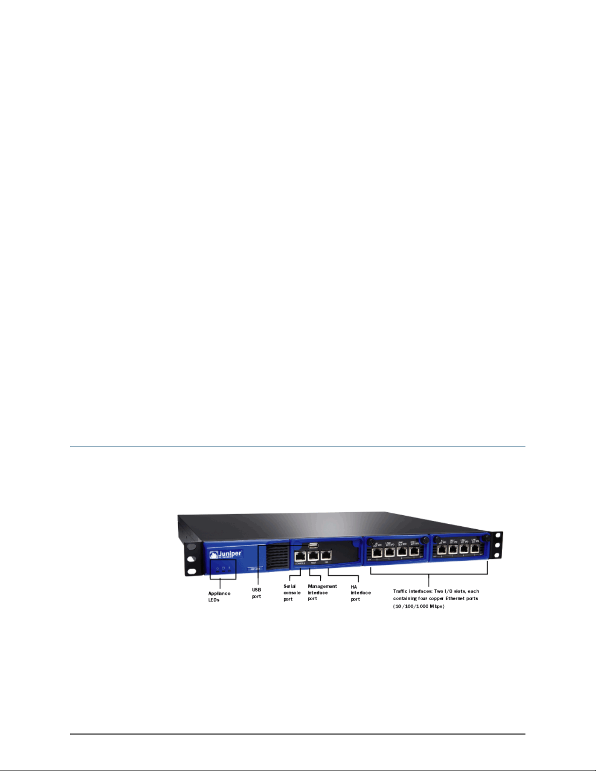
Related
Documentation
The IDP250 appliance is optimal for medium central sites or large branch offices. Figure
1 on page 3 shows the location of appliance LEDs and ports.
Figure 1: IDP250 Front Panel
System Status LEDs on page 4•
• USB Port on page 5
• Serial Console Port on page 5
• Management Interface Port on page 5
3Copyright © 2012, Juniper Networks, Inc.
Page 16

IDP250 Installation Guide
Power Supply
• High Availability Interface Port on page 6
• Traffic Interface Ports on page 7
• IDP250 Technical Specifications on page 59
The appliance has one power supply. It is a field replaceable unit (FRU). You can order
a replacement part through your Juniper Networks sales contact. The part number for
the IDP250 power supply FRU is UNIV-PS-300W-AC.
You can also order a power cord. The part number for the power cord is
CBL-JX-PWR-Country (varies by country).
Related
Documentation
Hard Drive
Fans
System Status LEDs
Replacing a Power Supply on page 53•
The appliance has one 80 GB hard drive. It is not a field replaceable unit (FRU).
When the system is cool, appliance fans spin at a slower speed to reduce noise and save
energy. As the system heats up, the fans run at a faster speed. In the event of fan failure,
the appliance fault LED blinks and the remaining fan or fans run at full speed until the
failed fan is replaced.
The fans for this model are not field replaceable units (FRUs).
Table 6 on page 4 describes system status LED states.
Table 6: System Status LED States
DescriptionStatusLED
System is powered on.Solid greenPower
System is powered off.Off
Hard disk is active.Flashing amberHard Drives
Hard drive has no activity.Off
Copyright © 2012, Juniper Networks, Inc.4
Page 17
USB Port
Serial Console Port
Chapter 1: Hardware Overview
Table 6: System Status LED States (continued)
DescriptionStatusLED
Power failure.Slowly blinking redFault
Fan failure.Quickly blinking red
Overheating.Solid red
Heat and power are normal.Off
The appliance has a USB port you can use to reimage the appliance, if necessary. The
part number is IDP-FLASH (IDP75, IDP250, IDP800) or IDP-FLASH-8200 (IDP8200).
The console serial port provides access, using an RJ-45 connector, to the command-line
interface (CLI).
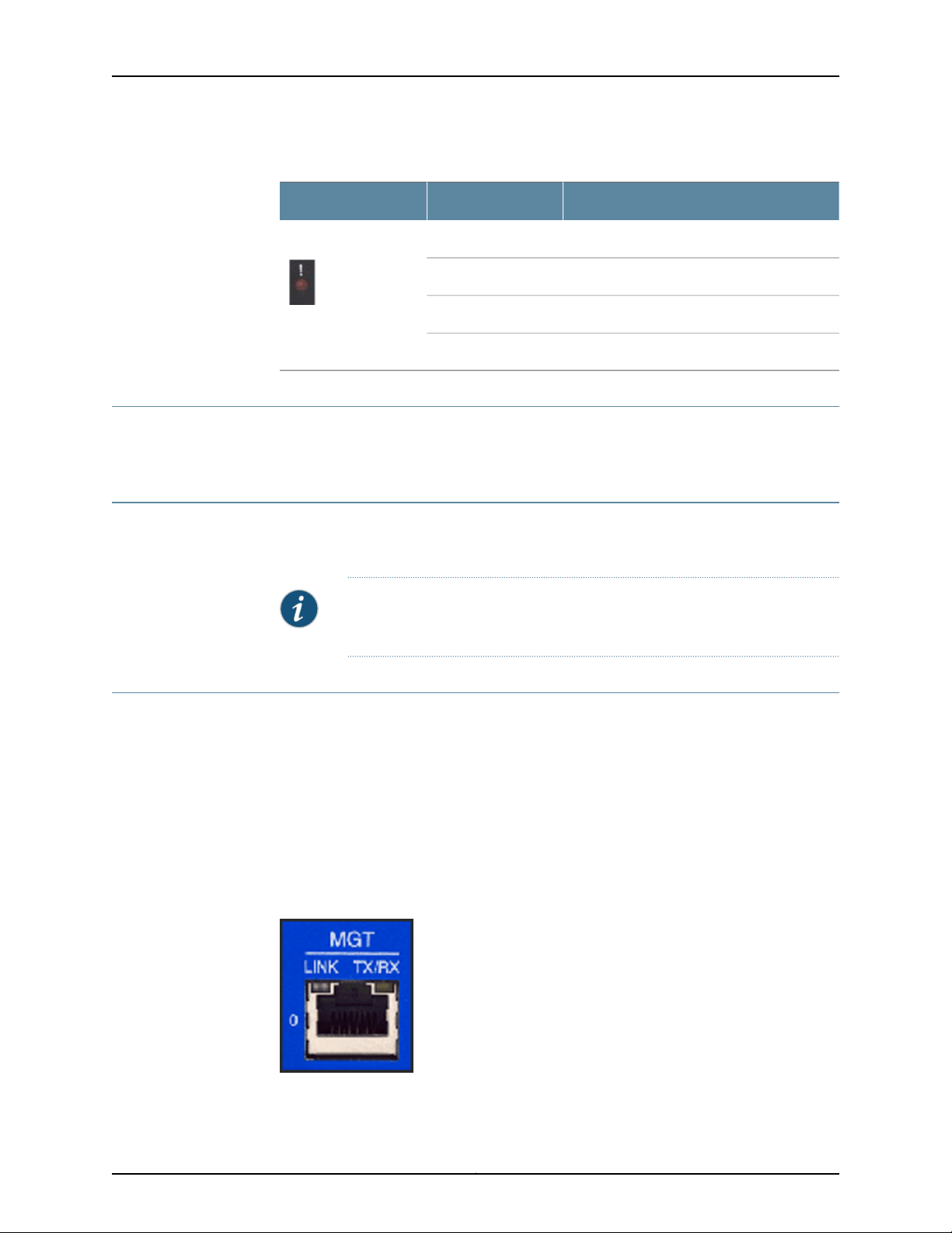
Management Interface Port
The management interface port is a10/100/1000 Mbps Ethernetport. Inthe configuration
and logs, the port is eth0. Use this port as a dedicated management port, connecting the
device to a switch accessible by your management subnet.
The IP address you assign the management port is the IP address you use to connect to
the Appliance Configuration Manager (ACM) when you initially configure the device. It is
also the address the Networkand Security Manager (NSM) uses toconnect to the device.
Figure 2 on page 5 shows the management interface port LEDs.
Figure 2: Management Interface Port LEDs
NOTE: Although both the console serial port and the management port use
RJ-45 connectors, do not plug the network cable into the console serial port.
Table 7 on page 6 describes the management interface port LED states.
5Copyright © 2012, Juniper Networks, Inc.
Page 18
IDP250 Installation Guide
Table 7: Management Port LEDs
DescriptionStateLED
Link is present.Glows greenLINK
Activity.Blinks green
No link is present.Off
Connection is 1000 Mbps.OrangeTX/RX
Connection is 100 Mbps.Green
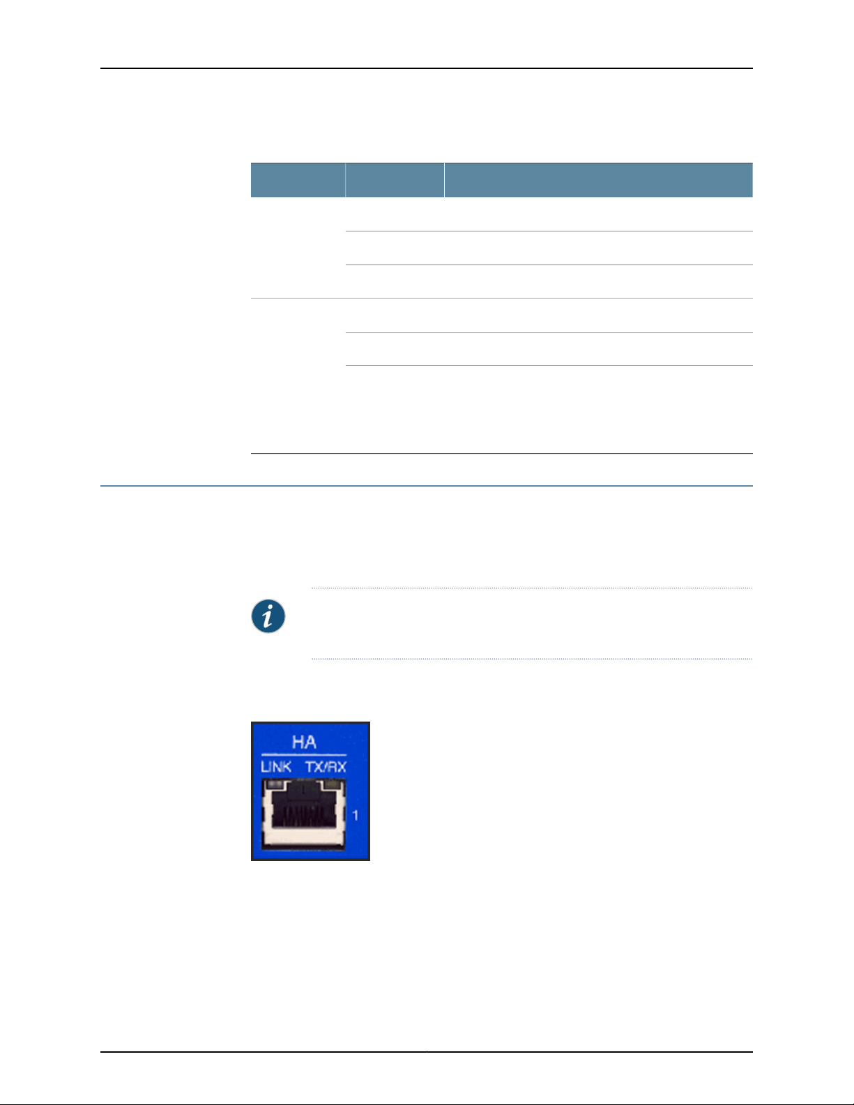
High Availability Interface Port
The high availability interface port is a 10/100/1000 Mbps Ethernet port. In the
configuration and logs, the port is eth1. The high availability interface is a dedicated
interface used to share state information among IDP appliances in a high availability
cluster.
NOTE: IDP OS 5.1 supports high availability. IDP OS 5.0 does not support
high availability.
Figure 3 on page 6 shows the management interface port LEDs.
Figure 3: High Availability Interface Port LEDs
Off
If LINK indicates activity, TX/RX off indicates connection
is 10 Mbps.
If LINK indicates no activity, TX/RX off indicates no activity
as well.
Table 8 on page 7 describes the high availability interface port LED states.
Copyright © 2012, Juniper Networks, Inc.6
Page 19
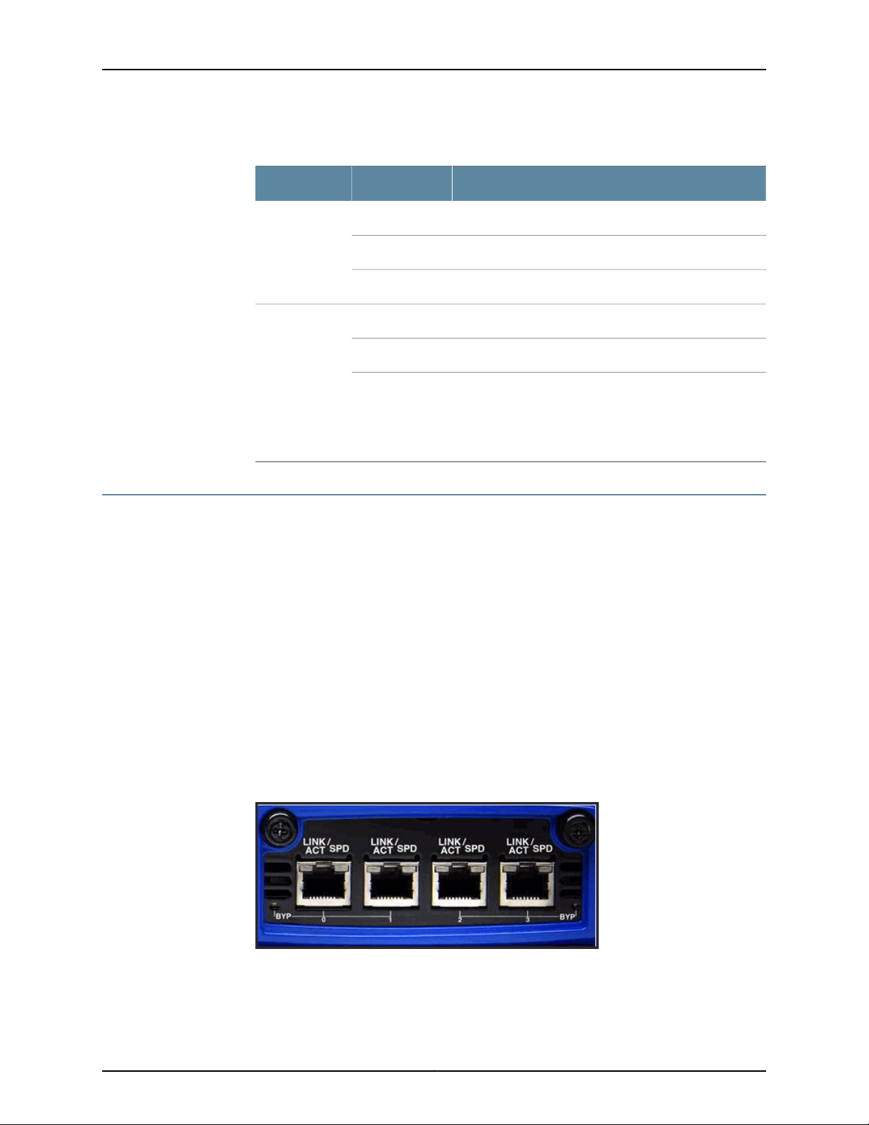
Table 8: High Availability Port LEDs
DescriptionStateLED
Link is present.Glows greenLINK
Activity.Blinks green
No link is present.Off
Connection is 1000 Mbps.OrangeTX/RX
Connection is 100 Mbps.Green
Chapter 1: Hardware Overview
Traffic Interface Ports
You use the traffic interfaceports toconnect theappliance to your network. The interfaces
receive and forward traffic. The type and capacity of interface ports vary by model.
The following topics describe features of traffic interface ports:
•
•
•
•
•
Copper Ports
Figure 4 on page 7 shows copper port LEDs.
Figure 4: Copper Port LEDs
Off
If LINK indicates activity, TX/RX off indicates connection
is 10 Mbps.
If LINK indicates no activity, TX/RX off indicates no activity
as well.
Copper Ports on page 7
Fiber Ports on page 8
Traffic Interface Features on page 9
NICs Off on page 12
Peer Port Modulation on page 13
Table 9 on page 8 describes copper port LED states.
7Copyright © 2012, Juniper Networks, Inc.
Page 20
IDP250 Installation Guide
Table 9: Copper Port LEDs
DescriptionStateLED
Link is present.Glows greenLINK ACT
Activity.Blinks green
No link present.Off
Connection is 100 Mbps.GreenLINK SPD
Connection is 1 Gbps.Yellow
Fiber Ports
Off
If LINK ACT is on, the connection is 10 Mbps. If LINK ACT is
off, LINK SPD off indicates no link is present as well.
Interface is not in bypass mode.GreenBYP
Interface is in bypass mode.Yellow
Interface is turned off (NICs off state).Off
NOTE: For copper interface ports, if failure or shutdown triggers NICs off
state, LINK ACT and LINK SPD LEDs are turned off.
Figure 5 on page 8 shows fiber port LEDs.
Figure 5: Fiber Port LEDs
Table 10 on page 9 describes fiber port LED states.
Copyright © 2012, Juniper Networks, Inc.8
Page 21

Table 10: Fiber Port LEDs
Chapter 1: Hardware Overview
DescriptionStateLED
Link is present.Glows greenLINK ACT
Activity.Flashes green
No link present.Off
Connection is 100 Mbps.GreenLINK SPD
Connection is 1 Gbps.Yellow
Connection is 10 Gbps.Orange
Traffic Interface Features
Traffic interfaces are network interface cards (NICs). In the IDP Series configuration
abstraction, a pair of traffic interfaces is called a virtual router. For example, virtual router
vr1 comprises interfaceports eth2 and eth3. For each virtualrouter, you usethe Appliance
ConfigurationManager (ACM) toconfigure the deploymentmode (snifferor transparent)
and bypass options (internal, external, oroff). You also configure aglobal setting (affects
traffic flow throughall interfaces) onhow to handle Layer 2 packets. The following topics
describe these settings:
•
Deployment Mode on page 10
•
Layer 2 Bypass on page 10
•
Internal Bypass on page 10
•
External Bypass on page 12
For guidance on using ACM to configure virtual router settings, see the ACM online help.
Off
If LINK ACT is on, the connection is 10 Mbps. If LINK ACT is
off, LINK SPD off indicates no link is present as well.
Interface is not in bypass mode.GreenBYP
Interface is in bypass mode.Yellow
Interface is turned off (NICs off state).Off
NOTE: For fiber interface ports, if failure or shutdown triggers NICs off state,
LINK ACT and LINK SPD LEDs remain lit.
9Copyright © 2012, Juniper Networks, Inc.
Page 22

IDP250 Installation Guide
Deployment Mode
You specify a deployment mode for each virtual router. You have two options:
•
Transparent—In an in-path, transparent mode deployment, traffic arrives in one
interfaceand is forwarded through the other. The IDP Series appliance detects attacks
and takes action according to your security policy rules. You connect the IDP Series
traffic interfaces to firewalls or switches in the network path.
•
Sniffer—In an out-of-path, sniffer mode deployment, the IDP Series appliance can
detect attacks but can take only limited action. You connect the IDP Series traffic
interfaces to a mirrored port of a network hub or switch.
Layer 2 Bypass
You enable or disable Layer 2 bypass to determine how the IDP Series device handles
Layer 2 packets.
When the IDP Series appliance is deployed in the path ofnetwork traffic, itcan take three
types of actions on the packets it receives:
•
Drop it.
•
Pass it through.
•
Process it according to IDP OS rules to determine whether to drop it, forward it, rate
limit, and so forth.
The IDP Series appliance processes Layer 2 traffic as follows:
•
Processes address resolution protocol (ARP) and Layer 2 packets related to internet
protocol (IPv4) traffic.
•
Drops all other Layer 2 traffic, unless the Layer 2 bypass setting is enabled.
•
When Layer 2 bypass is enabled, the IDP Series device passes through Layer 2 packets
related to bypass and high availability deployments (such as heartbeats or Bridge
Protocol Data Unit (BPDU) packets), and non-IPv4 packets and packets related to
switching and routing protocols, such as IPv6, internetwork packet exchange (IPX),
Cisco Discovery Protocol (CDP), and interior gateway routing protocol (IGRP), and so
forth.
The IDP Series appliance processes TCP/IP traffic according to implicit rules related to
traffic anomaly detection and explicit rules specified in the security policy.
Internal Bypass
The Internal Bypass feature is intended for deployments where a network security policy
privileges availability over security. In the event of failure or graceful shutdown, traffic
bypasses the IDP processing engine and is passed through the IDP Series device
uninspected.
The Internal Bypass feature operates through a timing mechanism. When enabled, the
timer on traffic interfaces counts down to a bypass trigger point. When the IDP Series
Copyright © 2012, Juniper Networks, Inc.10
Page 23
Chapter 1: Hardware Overview
appliance is turned on and available, it sends a reset signal to the traffic interface timer
so that it does not reach the bypass trigger point. If the IDP OS encounters failure, then
it fails to send the reset signal, the timer counts down to the trigger point, and the traffic
interfaces enter a bypass state. If the IDP Series appliance is shut down gracefully, the
traffic interfaces immediately enter bypass.
With copper NICs, the bypass mechanism joins the interfaces mechanically to form a
circuit that bypasses IDP processing. Packets traverse the IDP Series device as if the path
from eth2 (receiving interface) to eth3 (transmiting interface) were a crossover cable.
No packet inspection or processing occurs.
With fiber NICs, the bypass mechanism uses use optical relays instead of copper relays.
During normal operations, the optical relays send light to thebuilt-in opticaltransceivers.
When bypass is triggered, therelaysflip state, and the light signal isredirectedto optically
connect the two external ports.
Figure 6 on page 11 compares the data path when Internal Bypass is enabled but not
activated with the data path when Internal Bypass is activated.
Figure 6: Internal Bypass
When the IDP OS resumes healthy operations, it sends a reset signal to the traffic
interfaces, and the interfaces resume normal operation.
NOTE: All copper port traffic interfaces support internal bypass. Some, but
not all, fiber port traffic interfaces support internal bypass. Check with your
sales contact for applicable part numbers.
NOTE: Bypass settingsare applicableonly for deploymentswhere the virtual
router is in the network path—transparent mode deployments.
11Copyright © 2012, Juniper Networks, Inc.
Page 24
IDP250 Installation Guide
NOTE: The bypass and PPM featuresare applied independently. The Internal
Bypass setting is related to the status of the IDP operating system. The peer
port modulation setting is related to the status of the link. It is possible to
have a healthy operating system and a link with status down, or a failed
operating system and a link with status up.
External Bypass
The External Bypass setting supports third-party external bypass units. Deployments
with external bypass units depend on the functionality of the external bypass unit to
check the status of the IDP Series appliance and make the determination whether to
send packets through or around the IDP Series device. Most external bypass units test
for availability by sending heartbeat packets through the device. If the packets reach the
expected destination, the external bypass unit allows the traffic to continue through the
IDP Series appliance. If the packets fail to reach the expected destination, the external
bypass unit determines the IDP Series is unavailable, so it forwards traffic around the
IDP Series device. The IDP Series supports external bypass solutions by allowing the
heartbeat traffic to pass through the device regardless of the Layer 2 Bypass setting. In
other words, if you disable Layer 2 Bypass and enable External Bypass, most Layer 2
traffic will be dropped but the heartbeat traffic used in the external bypass deployment
will bepassed through. Figure 7 on page 12 comparesthe data path when ExternalBypass
is enabled but not activated with the data path when External Bypass is activated.
NICs Off
Figure 7: External Bypass
The NICs Offsetting isintended to supportnetwork security policies that privilege security
over availability—you want the network path to be unavailable if the IDP Series device
Copyright © 2012, Juniper Networks, Inc.12
Page 25

Peer Port Modulation
Chapter 1: Hardware Overview
is in a state in which it cannot inspect the traffic. With NICs Off configured, in the event
of failure or graceful shutdown, the interfaces are turned offand the IDPSeries appliance
becomes apoint of failure. If your network design includes redundant network paths, you
can configure your routers to detect the downed IDP Series interfaces and choose an
alternate path.
The peer port modulation (PPM) feature supports deployments where routers monitor
link state to makerouting decisions.In these deployments, arouter might be setto monitor
link state on only one side of the IDP Series appliance. Suppose, for example, the router
monitors only the inbound interface. Suppose the inbound interface remains up but the
outbound interface goes down. The router watching the inbound link would detect an
available link and forward traffic to the IDP Series appliance. Traffic would be dropped
at the point of failure—the outbound link. PPM propagates a link loss state for one traffic
interface to all interfaces in the IDP Series virtual router.
When PPM is enabled,a PPM daemonmonitors the health of IDP Series traffic interfaces
belonging to the same virtual router. If atraffic interface loses link, the PPM process turns
off any associated network interfaces in the same virtual router so that other network
devices detect that the virtual router is down and route around it. For example, assume
you have enabled PPM and configured IDP Series virtual routers as shown in Figure 8 on
page 13.
Figure 8: Peer Port Modulation
Suppose there is a network problem and eth3 goes down. The PPM daemon detects this
and turns off the other interface in vr0: eth2. The interfaces in vr1, vr2, and vr3 are
unaffected. After the you fix the problem with eth3, the PPM daemon detects this, and
turns on eth2.
13Copyright © 2012, Juniper Networks, Inc.
Page 26

IDP250 Installation Guide
NOTE: The PPM feature is independent of the bypass feature (NIC state
setting). PPM is related to the status of the link, not the status of the IDP
operating system. A link can be down even when the IDP operating system
is healthy. Note, however, that PPM runs as a control plane process and
operates only when the IDP Series appliance is turned on and the control
plane is available. If the IDP operating system is unavailable, the PPM feature
is also unavailable, regardless of the setting for the NIC state.
Copyright © 2012, Juniper Networks, Inc.14
Page 27

CHAPTER 2
Software Overview
This chapter includes the following topics:
•
On-Box Software Overview on page 15
•
Centralized Management with NSM Overview on page 16
•
J-Security Center Updates Overview on page 17
On-Box Software Overview
You use on-box software to get the appliance up and running in the desired deployment
mode, to configure appliance interfaces, and to establish communication with Network
and Security Manager (NSM). You can also use on-box utilities to manage appliance
processes or generate on-box reports.
Table 11 on page 15 summarizesthe IDP Series on-boxmanagement software and utilities.
Table 11: IDP Series On-Box Utilities
EasyConfig
QuickStart
ACM
scio utility
UsageSoftware
When you install anew appliance, you canuse the EasyConfigscript toassign
the appliance an IP address and initialize a simple configuration.
To run the EasyConfig script, connect to the serial port console.
When you install a new appliance, you can use QuickStart to deploy the
appliance with the default virtual router configured in either sniffer or
transparent mode and all configuration defaults.
To access QuickStart, connect to the management interface and open the
QuickStart URL in your browser.
When youinstall a new appliance,you can use ACM to configure the network
settings, network interfaces, and user access.
To access ACM, connect to the management interface and open the ACM
URL in your browser.
You can use the scio utility to get or set appliance configuration information.
For details, see the IDP Series Administration Guide.
15Copyright © 2012, Juniper Networks, Inc.
Page 28

IDP250 Installation Guide
Table 11: IDP Series On-Box Utilities (continued)
UsageSoftware
idp.sh utility
sctop utility
bypassStatus
utility
IDP Reporter
You can use the idp.sh utility to start, stop, or get status information on
appliance processes.
For details, see the IDP Series Administration Guide.
You can use the sctop utility to monitor connection tables and view status.
For details, see the IDP Series Administration Guide.
You can use bypassStatus commands to display settings for the daemon
that monitors traffic interface NIC state.
For details, see the IDP Series Administration Guide.
You can use the IDP Reporter to view statistics on attacks the IDP Series
appliance has detected and responded to, as well as application volume
tracking (AVT) statistics.
For details, see the IDP Reporter User’s Guide.
Centralized Management with NSM Overview
Juniper Networks Network and Security Manager (NSM) is a central management server
capable of managing hundreds of IDP Series appliances and other Juniper Networks
devices, such as ScreenOS firewalls, SA Series appliances, and IC Series appliances. You
typically deploy NSM in a management subnet accessible to the NSM-managed devices.
Figure 9 on page 16 illustrates the flow of information between the tiers of the central
management solution: the NSM user interface, theNSM server, and IDPSeries appliances.
Figure 9: IDP Series-NSM Communication
The IDP Series configuration, security policies, attack objects, and log records are stored
in NSM serverdatabasesand administeredusing theNSM userinterface. Communication
between the NSM server and IDP Series appliances, and between the NSM server and
the NSM user interface, is encrypted and authenticated.
Copyright © 2012, Juniper Networks, Inc.16
Page 29

For IDP Series deployments, centralized management provides the following benefits:
•
Centralized management for IDP Series appliances and other network devices
•
Consolidated logs from different devices in a single repository
•
Centralized management of enterprise security policies
•
Simplified management for attack signature updates
•
Role-based administration
For information about installing NSM and using NSM distributed management features,
management objects (such as address objects, service objects, and templates), and
navigational and display features, see the NSM documentation.
J-Security Center Updates Overview
The Juniper Networks Security Center (J-Security Center) routinely makes important
updatesavailableto IDPsecurity policycomponents, including updatesto theIDP detector
engine and the NSM attack database.
Chapter 2: Software Overview
The IDP detectorengine is a dynamic protocol decoder that includes support for decoding
more than 60 protocols and more than 500 service contexts. You should update IDP
detectorengine whenyou first installIDP software,whenever you upgrade,and whenever
alerted to do so by Juniper Networks. You can view release notes for detector engine
updates at http://www.juniper.net/techpubs/software/management/idp/de/.
The NSM attack database stores data definitions for attack objects. Attack objects are
patterns comprising stateful signatures and traffic anomalies. Security policy rules direct
the IDP engine to inspect traffic for attack objects. We recommend you schedule
automatic updates for the NSM attack database.
For more informationabout detector engine and attack object updates, see the IDP Series
Administration Guide.
17Copyright © 2012, Juniper Networks, Inc.
Page 30

IDP250 Installation Guide
Copyright © 2012, Juniper Networks, Inc.18
Page 31

PART 2
Performing the Installation
•
Installation Overview on page 21
•
Installing the Appliance to Your Equipment Rack and Connecting Power on page 23
•
Performing the Initial Network Configuration and Licensing Tasks on page 27
•
Connecting the IDP Traffic Interfaces to Your Network and Verifying Traffic
Flow on page 33
19Copyright © 2012, Juniper Networks, Inc.
Page 32

IDP250 Installation Guide
Copyright © 2012, Juniper Networks, Inc.20
Page 33

CHAPTER 3
Installation Overview
This chapter includes the following topics:
•
Before You Begin on page 21
•
Basic Steps on page 22
Before You Begin
The location of the device, the layout of the mounting equipment, and the security of
your wiring room are crucial for proper system operation.
CAUTION: To prevent abuse and intrusion by unauthorized personnel, install
the appliance in a secure environment.
Observing the following precautions can prevent shutdowns, equipment failures, and
injuries:
•
Beforeinstallation, always check that the powersupply isdisconnected from any power
source.
•
Ensure that the room in which you operate the device has adequate air circulation and
that the room temperature does not exceed 104°F (40°C).
•
Do not place the device in an equipment-rack frame that blocks an intake or exhaust
port. Ensure that enclosed racks have fans and louvered sides.
•
Correct these hazardous conditions before any installation: moist or wet floors, leaks,
ungrounded or frayed power cables, or missing safety grounds.
For a comprehensive presentation on the precautions you must take to prevent personal
injury and damage to the equipment, see the Juniper Networks Security Products Safety
Guide.
21Copyright © 2012, Juniper Networks, Inc.
Page 34

IDP250 Installation Guide
Basic Steps
Take the following basic steps to install the appliance and connect it to your network:
1. Read the release notes for your release. Release notes make you aware of supported
and unsupported features, known issues, and fixed issues. Go to
http://www.juniper.net/techpubs/software/management/idp/ and download the
release notes for your release.
2. Become familiar with the safety and security guidelines that pertainto yourinstallation.
See “Before You Begin” on page 21.
3. Decide on the physical location for the appliance. The location depends on your
deployment mode, the location of your network devices, and compliance with your
company security policy.
4. Install the appliance into your equipment rack. See Rack Mounting Kits and Required
Tools.
Although you can place the appliance on a desktop for operation, we do not
recommend deploying it in this manner.
5. Connect power cables and power on. See Connecting Power.
6. Perform the initial configuration steps. See “Performing the Initial Configuration” on
page 27.
7. Install the appliance license key. See “Installing the Product License Key” on page 31.
NOTE: In these steps, you are instructed to install the product license key
before you add the appliance to NSM. If you install the product license
key after you add the appliance to NSM, you must re-add the appliance
to NSM.
8. Connect the appliance to your network. See “Guidelines for ConnectingIDP Interfaces
to Your Network Devices” on page 33.
9. Verify connectivity. See “Verifying Traffic Flow” on page 36.
10. In NSM, add the IDP Series appliance to the NSM device manager. See “Adding a
Reachable IDP Device to NSM” on page 41.
11. Upgrade the IDP software to the current release, update the IDP detector engine
firmware,and updatethe NSMattackobject database.See “Updating Software(NSM
Procedure)” on page 49.
Copyright © 2012, Juniper Networks, Inc.22
Page 35

CHAPTER 4
Installing the Appliance to Your
Equipment Rack and Connecting Power
This chapter includes the following topics:
•
Rack Mounting Kits and Required Tools on page 23
•
Mounting to Midmount Brackets on page 24
•
Mounting to Rack Rails on page 25
•
Connecting Power on page 25
Rack Mounting Kits and Required Tools
Table 12 on page 23 describes the rack mounting hardware included in a standard
shipment and required tools that are not included in a standard shipment.
Table 12: Rack Mounting Hardware and Required Tools
Related
Documentation
DescriptionHardware
Rack mounting kit
Required tools
The standard shipment for 1 RU models includes a single pair of mounting
brackets/ears. Use the brackets as follows:
•
Position the brackets in the front position to front-mount.
•
Position the brackets in the middle position to midmount.
If you require additional rack mounting hardware, such as rack rails, contact
your sales representative for details on rack mounting kits to suit your needs.
The part number for the standard rail kit is UNIV-MR1U-RAILKIT.
The followingtools are notincluded inthe standard shipmentand arerequired
to install the appliance into an equipment rack:
•
Number 2 Phillips-head screwdriver
•
Rack-compatible screws
Mounting to Midmount Brackets on page 24•
• Mounting to Rack Rails on page 25
23Copyright © 2012, Juniper Networks, Inc.
Page 36

IDP250 Installation Guide
Mounting to Midmount Brackets
To mount the appliance using the midmount brackets:
1. Attachone rack-mountingbracket to eachside ofthe chassiswith the bracket screws.
Figure 10: 1-RU Midmount Bracket
Related
Documentation
2. With another person, place the chassis into position between rack posts in the
equipment rack and align the rack-mounting bracket holes with the rack post holes.
CAUTION: Be sure to leave at least two inches of clearance on the sides
of each chassis for the cooling air inlet and exhaust ports.
3. Secure the chassis to the rack with the rack screws.
Rack Mounting Kits and Required Tools on page 23•
Copyright © 2012, Juniper Networks, Inc.24
Page 37

Mounting to Rack Rails
To mount the device to equipment rack rails:
1. Attach the rails to each side of the chassis with the bracket screws. Make sure the
Figure 11: Rail with Hinged Rear Bracket
Chapter 4: Installing the Appliance to Your Equipment Rack and Connecting Power
hinged brackets are at the back of the device. Make sure the rails are positioned so
they reach the back of the rack when the device is mounted.
Related
Documentation
Connecting Power
2. Rotate the hinges on both rails so that they allow the device to slide into the rack.
3. With another person, slide the chassis and rails into the rack.
CAUTION: Be sure to leave at least two inches of clearance on the sides
of each chassis for the cooling air inlet and exhaust ports.
4. Secure the front brackets to the rack.
5. Rotate the rear brackets so they prevent the device from sliding forward.
6. Secure the rear brackets to the rack.
Rack Mounting Kits and Required Tools•
Power is provided to the appliance using 90/264 VAC from your facility.
To connect power:
1. Connect thepower cable (provided) tothe receptacle on the power supply at the rear
of each chassis.
2. Connect the other end of the power cable to the electrical outlet.
25Copyright © 2012, Juniper Networks, Inc.
Page 38

IDP250 Installation Guide
Copyright © 2012, Juniper Networks, Inc.26
Page 39

CHAPTER 5
Performing the Initial Network
Configuration and Licensing Tasks
This chapter includes the following topics:
•
Performing the Initial Configuration on page 27
•
Getting Started with the EasyConfig Wizard (Serial Console Port) on page 29
•
Getting Started with the QuickStart Wizard (Management Port) on page 30
•
Getting Started with the ACM Wizard (Management Port) on page 31
•
Installing the Product License Key on page 31
Performing the Initial Configuration
We recommend the following workflow to perform the initial configuration:
1. In the machine room, connect your laptop to the serial port and run the EasyConfig
script to assign the management interface an IP address you can reach from your
subnet.
2. From your desk, run the ACM wizard from your Web browser. Be sure to change the
default passwords.
In some circumstances, you might not be able to use the serial console or might prefer
to get started with a simple configuration for limited purposes. For these cases, we
support alternative methods for getting started. Table 13 on page 28 summarizes the
getting started configuration tools.
27Copyright © 2012, Juniper Networks, Inc.
Page 40

IDP250 Installation Guide
Table 13: Getting Started Configuration Tools
Defaults Applied:You Specify:Getting Started Tool
EasyConfig wizard
(Serial port)
(Management port)
ACM wizard
(Management port)
•
Management interface IP address and
netmask
•
Default route
•
Time zone, date, and time
•
Deployment mode (sniffer or transparent)
for the default virtual router(s)
•
Management interface IP address and
netmask
•
Passwords for root and admin
•
Fully qualified domain name
•
Trafficinterfaceconfiguration(speed/duplex,
NIC states, route table)
•
Virtual routers: deployment mode (sniffer or
transparent) and NIC bypass (internal,
external, or NICs off)
•
Peer port modulation
•
Layer 2 bypass (pass-through)
•
Network services (DNS, NTP, RADIUS, SSH)
•
ACM access
•
NSM connection information
•
One-time password(OTP)for interoperability
with Juniper Networks SA Series or UAC
devices
•
Root password: abc123
•
Fully qualified domain name: Blank
•
RADIUS support: Disabled
•
Network interfaces: Auto-negotiate
speed/duplex
•
Virtual routers:
•
Sniffer mode: One virtual router (vr0)
•
Transparent mode: One virtual router for
each pair of interfaces
•
NIC State: NICs off
•
DNS: Disabled
•
NTP: Disabled
•
SSH on management port: Enabled
•
Start the ACM process when the appliance
starts up: Enabled
Same as EasyConfig Wizard.Same as EasyConfig Wizard.QuickStart wizard
Related
Documentation
Getting Started with the EasyConfig Wizard (Serial Console Port) on page 29•
• Getting Started with the QuickStart Wizard (Management Port) on page 30
• Getting Started with the ACM Wizard (Management Port) on page 31
Copyright © 2012, Juniper Networks, Inc.28
Page 41

Chapter 5: Performing the Initial Network Configuration and Licensing Tasks
Getting Started with the EasyConfig Wizard (Serial Console Port)
We recommend you get started by running the EasyConfig wizard to assign an IP address
to the management interface. Then, you can access the ACM Wizard from a remote
location to complete the appliance configuration.
To perform the initial configuration with the EasyConfig wizard:
1. Connect one end of the provided RJ-45 null modem serial cable to the serial console
port located on the front of the appliance chassis.
2. Connect the other end of the cable to the serial port of your laptop.
3. Open a terminal emulation package such as Microsoft Windows HyperTerminal or
XModem. The settings for the software should be as follows:
•
9600 bps
•
8 data bits
•
No parity generation or checking
•
1 stop bit
•
No flow control
•
The serial port number where you connected the cable
4. Turn on the appliance.
If nothing appears in the terminal window, press Enter to display the boot messages.
5. Log into the appliance as root with the default password (abc123).
NOTE: After you have completed the initial configuration, we highly
recommend that you use ACM to change the default password.
The EasyConfig script runs automatically. The following text appears:
Configuring the deployment mode...
The currently supported deployment modes in EasyConfig are the following,
1. Sniffer <default>
2. Inline transparent
Choose the deployment mode? [1]
6. Press 1 or 2 and press Enter.
The following text appears:
Configuring Management interface...
The management interface is currently configured as:
IP: 192.168.1.1
Mask: 255.255.255.0
What IP address do you want to configure for the management interface?
[192.168.1.1]
29Copyright © 2012, Juniper Networks, Inc.
Page 42

IDP250 Installation Guide
7. Type an IP address and press Enter.
The following text appears:
What netmask do you want to configure for the management interface?
[255.255.255.0]
8. Type your netmask and press Enter.
The system configures your interfaces. The following text appears:
Configuring default route...
The current default route is: X.X.X.X
Do you want to change the default route? (y/n) [n]
9. Type Y and press Enter.
The following text appears:
What IP address do you want to configure as default route? [X.X.X.X]
10. Type your default route (gateway address) and press Enter.
The system asks if you want to change the system time.
Configuring system time...
Currently configured time is Wed Jan 18 16:32:32 PST 2006
Do you want to change the system time? (y/n) [n]
11. Type N if the time is correct. If the time is not correct, type Y and follow the prompts
to change the system time.
Configuration of the management port is now complete. EasyConfig does not run the
next time you log into the appliance.
Related
Performing the Initial Configuration on page 27•
Documentation
Getting Started with the QuickStart Wizard (Management Port)
If you cannot connect to the serial port, you can run the QuickStart wizard from the
management port to assign an IP address to the management interface.
To get started with the QuickStart wizard:
1. Connect one end of an Ethernet cable to the management interface port and the
other end to the Ethernet port of your laptop.
2. On your laptop, open a Web browser.
3. In the browser Address or Location box, enter https://192.168.1.1.
NOTE: ACM access uses SSL, so you must type https:// and not http://.
4. Log in as the user root with the default password (abc123).
Copyright © 2012, Juniper Networks, Inc.30
Page 43

Chapter 5: Performing the Initial Network Configuration and Licensing Tasks
NOTE: After you have completedthe initial configuration, we recommend
highly that you use ACM to change the default password.
5. Click QuickStartto startthe QuickStart wizard. Complete the wizard steps asdescribed
in the online Help.
If youprefer, youcan click ACM instead andrun the ACM wizard atthis point. However,
the ACM wizard entails a lengthier configuration. You might be more comfortable
running the ACM wizard over the network.
Related
Performing the Initial Configuration on page 27•
Documentation
Getting Started with the ACM Wizard (Management Port)
You use the ACM wizard to complete the appliance configuration.
To get started with the ACM wizard:
1. Run the EasyConfig wizard or QuickStart wizard to assign the management interface
an IP address you can reach from your subnet.
2. Connect one end of a CAT-5 cable to the management interface port and the other
end to the switch or hub (recommended).
3. Verify that the link LED on the management port is green, indicating an active
connection.
4. Return to your desk and open a Web browser.
5. In the browser Address or Location box, enter https:// IP, where IP is the IP address
you assigned to the management interface. For example, if you configured the IP
address 10.100.200.1, enter https://10.100.200.1.
NOTE: ACM access uses SSL, so you must type https:// and not http://.
6. Type the default user name (root) and password (abc123).
7. Click ACM to start the ACM wizard. Complete the wizard steps as described in the
online Help.
Related
Performing the Initial Configuration on page 27•
Documentation
Installing the Product License Key
IDP OS 4.1 and later releases require you to install a permanent license key.
31Copyright © 2012, Juniper Networks, Inc.
Page 44

IDP250 Installation Guide
To install the permanent license key:
1. Open a Web browser and navigate to the Juniper Networks License Management
System Tool (LMS tool):
https://www.juniper.net/lcrs/license.do
2. Authenticate with your Juniper Networks customer username and password.
3. Use the LMS tool to generate a new license.
You must provide the device serial number. You can locate the serial number in the
following ways:
•
In ACM, the serial number is displayed in the lower-left hand corner of the home
page.
•
From the CLI, run the scio getsystem command to display system information,
including the serial number.
Save the license as a text file named lic.txt.
4. Connect to the IDP OS command-line interface:
•
Use SSH to connect to the IP address or hostname for the management interface.
Log in as admin and enter su – to switch to root.
•
If you prefer, make a connection through the serial port and log in as root.
5. Use SCP or FTP to copy the license file to the IDP Series appliance. The IDP Series
appliance does not run an FTP server, so you have to initiate the FTP session from the
IDP Series appliance.
6. Change directory to the temporary directory:
[root@localhost ~] cd /tmp
7. Change permissions on the file to enable read, write, and execute:
[root@localhost ~] chmod 777 lic.txt
8. Run the following scio command to add the license key:
[root@localhost ~] scio lic add lic.txt
9. Run the following scio command to verify you have successfully added the license
key:
[root@localhost ~] scio lic list
[root@localhost ~]# scio lic list
ID Machine ID Issue Date Expiration OK
Feature
-- ---------------- ------------------------ ------------------------ -------
------------------1 Upgrade Tue Apr 25 00:00:00 2006 Sat Apr 25 00:00:00 2009 Y
idp_key
[root@localhost ~]#
Related
Documentation
• Basic Steps on page 22
Copyright © 2012, Juniper Networks, Inc.32
Page 45

CHAPTER 6
Connecting the IDP Traffic Interfaces to
Your Network and Verifying Traffic Flow
This chapter includes the following topics:
•
Guidelines for Connecting IDP Series Interfaces to Your Network Devices on page 33
•
Choosing Cables for Traffic Interfaces (Copper Ports) on page 34
•
Connecting and Disconnecting Fiber Cables on page 35
•
Verifying Traffic Flow on page 36
Guidelines for Connecting IDP Series Interfaces to Your Network Devices
We recommend you deploy the IDP Series appliance between gateway firewalls and
DMZ or internal networks.
Table 14 on page 33 provides guidelines for connecting IDP Series interfaces to your
network.
Table 14: Interface Connection Guidelines
Cable Connection GuidelinesPort
Management port
NSM must be able to reach the IDP Series appliance through this connection.
1. Connect one end of a CAT-5 cable into the MGMT port located at the front of the
chassis.
2. Connect the other end to a switch or hub (recommended) in your network.
33Copyright © 2012, Juniper Networks, Inc.
Page 46

IDP250 Installation Guide
Table 14: Interface Connection Guidelines (continued)
Cable Connection GuidelinesPort
Traffic interface ports
Sniffer Mode – Copper Ports
1. Connect one end of a CAT-5 straight-through cable to a traffic interface port located
at the front of the chassis.
2. Connect the other end to the Switched Port Analyzer (SPAN) port of a switch or a
hub.
Sniffer Mode – Fiber Ports
1. Connect one end of an LC fiber cable to either one of the ports of a traffic interface
pair.
2. Connect the other end of the cable to the corresponding port of the switch.
Transparent Mode – Copper Ports
1. Connect one end of a CAT-5 straight-through cable to a traffic interface port located
at the front of the chassis.
2. Connect the other end to the corresponding port of a firewall, switch, or server.
3. Connect one end of a CAT-5 cable to the outbound port of a traffic interface pair (for
example, eth3).
4. Connect theother end toa corresponding the corresponding port of a firewall, switch,
or server.
Transparent Mode – Fiber Ports
1. Connect one end of an LC fiber cable to the inbound port of a traffic interface pair.
2. Connect the other end to the corresponding port of the switch.
3. Connect one end of an LC fiber cable to the outbound port of a traffic interface pair.
4. Connect the other end to the corresponding port of the switch.
Related
Documentation
Choosing Cables for Traffic Interfaces (Copper Ports) on page 34•
• Connecting and Disconnecting Fiber Cables on page 35
• Verifying Traffic Flow on page 36
Choosing Cables for Traffic Interfaces (Copper Ports)
This topic provides guidelines for choosing the correct cables to connect the appliance
to your network devices. It includes the following information:
•
Connecting Devices That Support Auto-MDIX on page 35
•
Connecting Devices That Do Not Support Auto-MDIX on page 35
•
Connecting Devices to Support Internal Bypass on page 35
Copyright © 2012, Juniper Networks, Inc.34
Page 47

Chapter 6: Connecting the IDP Traffic Interfaces to Your Network and Verifying Traffic Flow
Connecting Devices That Support Auto-MDIX
If you are connecting devices that support auto-MDIX (medium dependent interface
crossover), you can use either straight-through or crossover cables because auto-MDIX
negotiates the correct connection.
NOTE: IDP75, IDP250, IDP800, and IDP8200 support auto-MDIX.
Connecting Devices That Do Not Support Auto-MDIX
For connections to a firewall or server, use a crossover cable.
For connections to a switch or hub, use a straight-through cable.
NOTE: Conventionally, crossover cables have an orange outer jacket. If you
are not sure if your Cat 5 cable is a crossover or straight-through cable, lay
the two ends side-by-side and observe the order of the wire colors. If the
colors are in the same order, it is a straight-through cable; otherwise, it is a
crossover cable.
Connecting Devices to Support Internal Bypass
When internal bypass activates, it physically connects the pair of traffic interfaces to
each other with a crossover connection.
If the device does not support auto-MDIX, take special care to choose the right cables.
Suppose you plan to place the IDP Series appliance inlinebetween a firewalland a switch.
First, take note of the correct cable choice for a direct connection between the firewall
and switch. Would you use a straight-through cable or a cross-over cable?
If thetwodevices would beconnectedwith astraight-throughcable, then use a crossover
cable between the firewall and the IDP Series appliance and a straight-through cable
between the IDP Series appliance and the switch. When internal bypass activates and
crosses-over the connection between the IDP Series traffic interface pair, the connection
between the firewall and the switch will flow as if through a straight-through cable.
If the two devices would be connected with a cross-over cable, then use two
straight-through cables. When internal bypass activates, this will have the result of
creating one, long cross-over cable connecting the devices.
Connecting and Disconnecting Fiber Cables
The following procedures describe how to connect and remove a Gigabit Ethernet cable
to and from the transceiver.
35Copyright © 2012, Juniper Networks, Inc.
Page 48

IDP250 Installation Guide
To connect a Gigabit Ethernet cable to a transceiver:
1. Hold the cable clip firmly but gently between your thumb and forefinger with your
thumb on top of the clip and your finger under the clip. Do not depress the clip ejector
on top of the clip.
2. Make sure the transceiver ejector under the port is not pressed in; otherwise, if you
attempt to remove the cable the transceiver might come out with the cable still
attached.
3. Slide the clip into the transceiver port until it clicks into place. Because the fit is close,
you may have to apply some pressure to seat the clip. Apply pressure evenly and
gently to avoid clip breakage.
To remove a Gigabit Ethernet cable from a transceiver:
1. Hold the cable clip firmly but gently between your thumb and forefinger with your
thumb on top of the clip and your finger under the clip.
2. Use your thumb to gently press the clip ejector on top of the clip. Press down then
forward to loosen the clip from the transceiver port.
3. Gently but firmly pull the clip from the transceiver port.
Verifying Traffic Flow
Purpose After you have installed the appliance,run theinitial networkconfiguration,and connected
the appliance to your network, you can perform the following procedure to verify traffic
flows through the appliance.
Action To verify that traffic is flowing through the appliance:
1. Make sure the appliance is connected to a live traffic feed.
2. Connect to the IDP OS command-line interface:
3. Type sctop and press Enter.
4. Type s to see status information.
5. Examine the following information on the screen:
• Use SSH to connect to the IP address or hostname for the management interface.
Log in as admin and enter su – to switch to root.
• If you prefer, make a connection through the serial port and log in as root.
Protocol Packets Flows Sessions Peak Peak Time
Other 2 0 0 1 08/09/2006 03:08:07
ICMP 3 0 0 0 08/08/2006 18:03:51
UDP 3386 3 1 7 08/08/2006 19:31:01
TCP 151164 12 6 9 08/09/2006 07:01:36
Changes in the UDPand TCP flow and session counts indicate traffic is flowingthrough
the appliance.
Copyright © 2012, Juniper Networks, Inc.36
Page 49

Chapter 6: Connecting the IDP Traffic Interfaces to Your Network and Verifying Traffic Flow
Related
Documentation
• Basic Steps on page 22
37Copyright © 2012, Juniper Networks, Inc.
Page 50

IDP250 Installation Guide
Copyright © 2012, Juniper Networks, Inc.38
Page 51

PART 3
Adding the IDP Appliance to NSM
•
Adding the IDP Appliance to NSM on page 41
39Copyright © 2012, Juniper Networks, Inc.
Page 52

IDP250 Installation Guide
Copyright © 2012, Juniper Networks, Inc.40
Page 53

CHAPTER 7
Adding the IDP Appliance to NSM
This chapter includes the following topics:
•
Reviewing Compatibility with NSM on page 41
•
Adding a Reachable IDP Series Device to NSM on page 41
Reviewing Compatibility with NSM
Reviewthe release notes forinformation regarding compatibility between your IDPSeries
release and NSM release.
In some cases, you might be required to install a schema update on NSM to support the
IDP Series release. If so, follow the instructions in the release notes to install the schema
update.
NOTE: The schema update is also known as the forward support update.
Related
Documentation
Adding a Reachable IDP Device to NSM on page 41•
Adding a Reachable IDP Series Device to NSM
This procedure assumes theIDP Series device is reachable. A reachabledevice isa device
you have installed andinitialized, including configuring an IP address for themanagement
interface and connecting the management interface to the network. You complete the
reachable device workflow in cases where you set up the IDP Series appliance first and
add it to NSM second.
For information on a workflow where you add the device to NSM first and set up the IDP
Series appliance second, see the IDP Series Administration Guide.
41Copyright © 2012, Juniper Networks, Inc.
Page 54

IDP250 Installation Guide
To import an IDP Series device with a known IP address:
1. In the NSM navigation tree, select Device Manager > Devices.
Figure 12: NSM Add Device Wizard: Add Device
2. Click the + icon and select Device to display the Add Device wizard.
3. Select Device Is Reachable (default) and click Next to display the page where you
configure connection settings.
Figure 13: NSM Add Device Wizard: Connection Settings
4. In the Specify Connection Settings dialog box, enter the following connection
information:
•
Enter the IP address of the IDP Series device.
•
Enter admin for the username of the device admin user.
•
Enter the passwordfor the device adminuser. You set the password for admin when
you ran the ACM Wizard.
Copyright © 2012, Juniper Networks, Inc.42
Page 55

Chapter 7: Adding the IDP Appliance to NSM
•
Enter the password for the device root user. You set the password for root when
you ran the ACM Wizard.
NOTE: In NSM, passwords are case-sensitive.
•
Select SSH Version 2 and port 22.
Click Next.
The Wizard displays a page where you can verify the integrity of the connection
between the IDP Series appliance and NSM. Please wait a moment as the NSM
retrieves SSH key fingerprint information from the IDP Series appliance.
Figure 14: NSM Add Device Wizard: SSH Key Fingerprint Information
43Copyright © 2012, Juniper Networks, Inc.
Page 56

IDP250 Installation Guide
5. Log into the IDP OS command-line interface and verify the SSH key fingerprint.
Comparing the SSH key fingerprint information enables you to detect
man-in-the-middle attacks:
a. Connect to the IDP OS command-line interface:
•
Use SSHto connect tothe IP address orhostname forthe management interface.
Log in as admin and enter su – to switch to root.
•
If you prefer, make a connection through the serial port and log in as root.
b. Enter cd /etc/ssh.
c. Enter ssh-keygen -l -f ssh_host_dsa_key.
The command generates output similar to the following:
1024 f4:91:d0:04:b7:61:00:77:45:c3:cc:bd:af:b3:5b:a2 ssh_host_dsa_key.pub
After you have verified the SSH key fingerprint matches, click Next.
The Wizard displays a page where NSM retrieves and displays inventory information.
Pleasewait a moment as the NSM retrieves inventory information from the IDP Series
appliance.
Figure 15: NSM Add Device Wizard: Inventory Information
6. Verify that the device type, OS version, device serial number, and device mode are
correct.
7. Click Next to add the device to NSM. Upon success, NSM displays the following
message:
Copyright © 2012, Juniper Networks, Inc.44
Page 57

Chapter 7: Adding the IDP Appliance to NSM
Figure 16: NSM Add Device Wizard: Add Device Confirmation
8. Click Next to import the configuration from the IDP Series device. Upon success, NSM
displays the following message:
Figure 17: NSM Add Device Wizard: Configuration Import Confirmation
9. Click Finish.
For IDP OS 4.1 and later devices, NSM next runs a job to update the IDP device with
the Recommended IDP security policy. The Job Information dialog box shows the
status of the Update Device job.
10. After the job is complete, double-click the device in Device Manager to view the
imported configuration.
To check the device configuration status, mouse over the device and verify that the
device status displays Managed.
45Copyright © 2012, Juniper Networks, Inc.
Page 58

IDP250 Installation Guide
Figure 18: NSM Device Manager: Viewing Device Status
Related
Documentation
• Reviewing Compatibility with NSM on page 41
• Basic Steps on page 22
Copyright © 2012, Juniper Networks, Inc.46
Page 59

PART 4
Upgrading Software and Installing Field
Replaceable Units
•
Upgrading Software on page 49
•
Installing Field Replaceable Units on page 53
•
Reimaging the Appliance on page 55
47Copyright © 2012, Juniper Networks, Inc.
Page 60

IDP250 Installation Guide
Copyright © 2012, Juniper Networks, Inc.48
Page 61

CHAPTER 8
Upgrading Software
This chapter includes the following topics:
•
Updating Software (NSM Procedure) on page 49
•
Upgrading Software (CLI Procedure) on page 51
Updating Software (NSM Procedure)
To update IDP software:
1. Add the IDP software to the NSM GUI server.
2. Push the IDP software from the NSM GUI server to one or more IDP devices.
To add an IDP software image to the NSM GUI server:
1. Download the software image:
a. Go to https://www.juniper.net/customers/csc/software/ and log in with your
customer username and password.
b. Enter the IDP Series device serial number to display a view of applicable software
releases available for download.
c. Click the applicable link to display the software download page.
d. Download the software to a location you can access from your NSM client.
2. From the NSM main menu, select Tools > Software Manager to display the Software
Manager dialog box.
3. Click the + button to display the Open dialog box.
4. Selectthe IDP software image you just downloaded andclick Open to addthe software
image to the NSM GUI server.
5. Click OK.
49Copyright © 2012, Juniper Networks, Inc.
Page 62

IDP250 Installation Guide
To push the software image from the NSM GUI server to IDP Series devices:
1. From the NSM main menu, select Devices > Software > Install Device Software to
display the Install Device Software dialog box.
2. From the Select OS Name list, select ScreenOS/IDP.
3. From the Select Software Image list, select the image file you just added to the NSM
GUI server.
4. In the Select Devices list,select theIDP Series devices on whichto install the software
update.
5. Click Next and complete the wizard steps.
6. Select Automate ADM Transformation to automatically update the Abstract Data
Model (ADM) for the device after NSM installs the update.
NOTE: If you clear this setting, the update is installed onto the device, but
you cannot manage the device from NSM until the deviceADM is updated.
7. Click Finish to display upgrade status in the Job Information dialog box.
8. When the upgrade finishes, click Close to exit the Job Information dialog box.
9. In the NSM Device Manager, right-click the IDP Series device and select Import Device.
The software upgrade is complete.
Next Steps: Check to see if J-Security Center has released an update for the detector engine or
1.
attack database:
From the NSM main menu, select Tools > View/Update NSM attack database and
complete the wizard steps.
2. Push the updated IDP detector engine to IDP Series devices:
From the NSM main menu, select Devices > IDP Detector Engine > Load IDP Detector
Engine for ScreenOS and complete the wizard steps.
NOTE: Updating the IDP detector engine on a device does not require a
reboot of the device.
Copyright © 2012, Juniper Networks, Inc.50
Page 63

Chapter 8: Upgrading Software
3. Push a security policyupdate job toupdate attack objects in use in your security policy:
a. In NSM, select Devices > Configuration > Update Device Config.
b. Select devices to which to push the updates and set update job options.
c. Click OK.
Related
Upgrading Software (CLI Procedure) on page 51•
Documentation
Upgrading Software (CLI Procedure)
To upgrade IDP software from the CLI:
1. Download the software image to a host that runs an FTP server. Follow these steps:
a. Go to https://www.juniper.net/customers/csc/software/ and log in with your
customer username and password.
b. Navigateto IDP > ScreenOS Software Downloads (including NSM/GlobalPro, STRM,
IDP and NetScreen-Remote). In the row for IDP OS, click 5.1.
c. Save the sensor_version.sh file (where version is the number that identifies the
software release version).
2. Connect to the IDP OS command-line interface in one of the following ways:
•
Use SSH to connect to the IP address or hostname for the management interface.
Log in as admin and enter su - to switch to root.
•
If you prefer, make a connection through the serial port and log in as root.
NOTE: To make an SSH connection, you must have enabled SSH for the
management port (eth0). For details, see the ACM online Help.
3. Use SCP or FTP to copy the license file to the IDP Series appliance. The IDP Series
appliance does not run an FTP server, so you have to initiate the FTP session from the
IDP Series appliance.
4. Run the upgrade script by entering sh sensor_version.sh, where version is the number
that identifies the software release version. When the scripthas finished, enterreboot.
5. In the NSM Device Manager, right-click the device, select Adjust OS Version, and
complete the wizard steps.
6. In the NSM Device Manager, right-click the IDP Series device and select Import Device.
The software upgrade is complete.
Next Steps: Download the IDP detector engine and NSM attack database updates to the NSM
1.
GUI server:
51Copyright © 2012, Juniper Networks, Inc.
Page 64

IDP250 Installation Guide
From the NSM main menu, select Tools > View/Update NSM attack database and
complete the wizard steps.
2. Push the updated IDP detector engine to IDP Series devices:
From the NSM main menu, select Devices > IDP Detector Engine > Load IDP Detector
Engine for ScreenOS and complete the wizard steps.
NOTE: Updating the IDP detector engine on a device does not require a
reboot of the device.
3. Push a security policyupdate job toupdate attack objects in use in your security policy:
a. In NSM, select Devices > Configuration > Update Device Config.
b. Select devices to which to push the updates and set update job options.
c. Click OK.
Related
Documentation
• Updating Software (NSM Procedure) on page 49
Copyright © 2012, Juniper Networks, Inc.52
Page 65

CHAPTER 9
Installing Field Replaceable Units
This chapter includes the following topics:
•
Replacing a Power Supply on page 53
Replacing a Power Supply
The following procedure applies to models for which the power supply is a field
replaceable unit (FRU).
The appliance has two removable, hot-swappable power supplies. Units are shipped
with AC power supplies. You can order optional DC power supplies as FRUs. Table 15 on
page 53 lists the part numbers for IDP Series power supply FRUs.
You can also order a replacement power cord. The part number for the power cord is
CBL-JX-PWR-Country (varies by country).
Table 15: Part Numbers for IDP Series Power Supply FRUs
IDP800
IDP8200
Part NumberModel
UNIV-PS-300W-ACIDP250
UNIV-PS-400W-AC
UNIV-PS-710W-DC
UNIV-PS-700W-AC
UNIV-PS-710W-DC
To remove a power supply:
1. Go to the back of the device and locate the power supply you want to remove.
2. Locate the horizontal handle and the red lever in the upper left corner of the power
supply.
3. Lift the handle and push the lever to the right to unlatch the power supply.
4. With the lever pushed to the right, pull on the handle firmly to dislodge the power
supply from its seating.
53Copyright © 2012, Juniper Networks, Inc.
Page 66

IDP250 Installation Guide
5. Let go of the lever and slide out the power supply from the handle.
6. Let go of the handle and use both hands to slide the power supply the rest of the way
out.
To install a power supply:
1. Take the new power supply to the back of the device.
2. Hold the power supply with both hands with the red handle on the left side of the
power supply.
3. Align the power supply with the empty bay and slide the power supply into the bay.
4. Push firmly until you see and hear the red lever snap into place.
If the other power supply is on and powering the appliance, the appliance emits a
high-pitched whine and the power supply LED turns on.
5. Connect a power cord to the new power supply.
6. Attach the other end of the power cord to the power source.
The power supply LED turns amber to indicate that the power supply is receiving power.
The LED turns green to indicate that it is receiving power and is giving power to the
appliance (only occurs if appliance is on). The high-pitched whine stops and the PS FAIL
light on the front of the appliance turns off.
Copyright © 2012, Juniper Networks, Inc.54
Page 67

CHAPTER 10
Reimaging the Appliance
This chapter includes the following topic:
•
Reimaging and Relicensing an Appliance on page 55
Reimaging and Relicensing an Appliance
The appliance comes with software preinstalled. If needed, you can reinstall the factory
image. This process is known as reimaging the appliance. The reimaging process rewrites
the disk except for the partition containing /var/idp. If necessary and if possible, you
should save a copy of data or custom configuration files before reimaging.
If you reimage the appliance, you must also relicense it.
To reimage the appliance:
1. Connect a PC to the console serial port of the device, using the serial cable provided
with the appliance.
2. Power off the appliance.
3. Insert the USB flash memory stick that shipped with the appliance into the USB port
on the front of the appliance. If you have misplaced your USB flash memory stick,
contact Juniper Networks Technical Assistance Center (JTAC). The part number for
the USB flash memory stick is IDP-FLASH (IDP75, IDP250, IDP800) or
IDP-FLASH-8200 (IDP8200).
4. Power on the appliance.
The appliance boots from the USB stick and runs the reimaging process. Follow any
prompts on the serial console.
5. When the reimaging process has completed, remove the USB stick and reboot.
Next Steps 1. Configure the appliance as if a new installation.
2. Relicense the appliance.
3. Re-add the appliance to NSM.
4. Push updates to detector engine, attack object, and security policy.
55Copyright © 2012, Juniper Networks, Inc.
Page 68

IDP250 Installation Guide
Related
Documentation
• Performing the Initial Configuration on page 27
• Installing the Product License Key on page 31
• Adding a Reachable IDP Device to NSM on page 41
Copyright © 2012, Juniper Networks, Inc.56
Page 69

PART 5
Technical Specifications and Compliance
Statements
•
Technical Specifications on page 59
•
Compliance Statements on page 61
57Copyright © 2012, Juniper Networks, Inc.
Page 70

IDP250 Installation Guide
Copyright © 2012, Juniper Networks, Inc.58
Page 71

CHAPTER 11
Technical Specifications
This chapter includes the following topics:
•
IDP250 Technical Specifications on page 59
IDP250 Technical Specifications
Table 16 on page 59 lists physical specifications.
Table 16: Physical Specifications
ValueSpecification
1 RUForm Factor
1.69 in. (4.3 cm)Height
17 in. (43.2 cm)Width
15 in. (38.1 cm)Depth
16.5 lb (7.48 kg)Weight
Table 17 on page 59 lists power specifications.
Table 17: Power Specifications
ValueSpecification
100 to 240 VACAC input voltage
50 to 60 HzAC input line frequency
5.0 to 1.5 AAC input current
300 WMaximum power
Table 18 on page 60 lists power cord specifications.
59Copyright © 2012, Juniper Networks, Inc.
Page 72

IDP250 Installation Guide
Table 18: Power Cord Specifications
SpecificationsCountry
•
United States and Canada
UL-approved and CSA-certified
•
Flexible cord minimum spec: No. 18 (1.5 mm2SVT or
SJT, 3-conductor
•
Current capacity of 10A minimum
•
Earth-grounding attachment plug with NEMA 5-15P
(10A, 125V) configuration
Table 19 on page 60 list environmental specifications.
Table 19: Environmental Specifications
ValueSpecification
41° to 104° F (5° to 40° C)Operating temperature
-40° to 158° F (-40° to 70° C)Storage temperature
8% to 90% noncondensingRelative humidity (operating)
5% to 95% noncondensingRelative humidity (storage)
10,000 ft (3,048 m)Altitude (operating)
40,000 ft (12,192 m)Altitude (storage)
Heat dissipation rates depend on the traffic rate and the number and type of features
you have enabled. Table 20 on page 60 provides guidelines.
Table 20: Heat Dissipation Guidelines
BTU/hourWattsSpecification
27380Minimum
375110Maximum
Copyright © 2012, Juniper Networks, Inc.60
Page 73

CHAPTER 12
Compliance Statements
This chapter includes the following topic:
•
Standards Compliance on page 61
Standards Compliance
Table 21:
Standards ComplianceCategory
•
Safety
UL 60950, Third Edition — Safety of Information Technology Equipment
•
CSA C2.22 No. 60950, Third Edition — Safety of Information Technology
Equipment
•
EN 60950, 2000 —Safetyof Information TechnologyEquipment, including
Electrical Business Equipment
•
IEC 60950, Third Edition — Safety of Information Technology Equipment,
including Electrical Business Equipment
EMI
•
EN 55022, 1998 Class A
•
EN 61000-3-2
•
FCC Part 15 Class A
•
Industry Canada ICES-003 Class A
•
VCCI Class A
•
EN 55024, 1998Immunity
61Copyright © 2012, Juniper Networks, Inc.
Page 74

IDP250 Installation Guide
Copyright © 2012, Juniper Networks, Inc.62
Page 75

PART 6
Index
•
Index on page 65
63Copyright © 2012, Juniper Networks, Inc.
Page 76

IDP250 Installation Guide
Copyright © 2012, Juniper Networks, Inc.64
Page 77

Index
Symbols
1998 Class A compliance.....................................................61
A
ACM ........................................................................................15, 31
ACM Online Help.......................................................................ix
adding a device to NSM........................................................41
audience for documentation...............................................vii
auto-MDIX.................................................................................34
B
BTU/hour...................................................................................59
bypassStatus utility................................................................16
C
compliance
EMI standards..................................................................61
immunity standards.......................................................61
connecting power...................................................................25
console serial port.....................................................................5
copper ports
cable guidelines..............................................................34
CSA C2.22 No. 60950 compliance...................................61
customer support......................................................................x
contacting JTAC.................................................................x
D
DNS, setting..............................................................................28
E
EasyConfig ..........................................................................15, 29
EMI compliance........................................................................61
EMI compliance specifications...........................................61
EN 1998 compliance..............................................................61
EN 2000 compliance.............................................................61
EN 55022 compliance...........................................................61
EN 55024 compliance...........................................................61
EN 60950 compliance..........................................................61
EN 61000-3-2 compliance..................................................61
environmental specifications............................................59
F
fault LEDs.....................................................................................5
FCC Part 15 Class A compliance........................................61
fiber ports
cables.................................................................................35
H
HA port
LEDs.......................................................................................6
overview...............................................................................6
hard drives
LEDs.......................................................................................4
heat dissipation.......................................................................59
I
IC Series interoperation........................................................28
ICES-003 Class A compliance...........................................61
IDP Administration Guide......................................................ix
IDP Concepts and Examples Guide...................................ix
IDP Custom Attack Objects Reference and
Examples Guide....................................................................ix
IDP Reporter..............................................................................16
IDP Reporter User’s Guide.....................................................ix
IDP Series Installation Guide: IDP200, IDP600,
IDP1100.....................................................................................ix
idp.sh utility................................................................................16
IDP250...........................................................................................3
IDP250 Installation Guide.....................................................ix
IDP75 Installation Guide.........................................................ix
IDP800 Installation Guide....................................................ix
IDP8200 Installation Guide..................................................ix
IEC 60950 safety compliance............................................61
immunity standards...............................................................61
Industry Canada ICES-003 Class A compliance.........61
L
Layer 2 bypass setting...........................................................28
LEDs
fault........................................................................................5
HA port.................................................................................6
hard drive.............................................................................4
IDP250..................................................................................3
power....................................................................................4
traffic interface..............................................................7, 8
M
management interface, choosing cable for..................33
MDIX............................................................................................34
65Copyright © 2012, Juniper Networks, Inc.
Page 78

IDP250 Installation Guide
N
NSM
specifying connection information for...................28
updating software with...............................................49
NTP, setting...............................................................................28
O
one time password.................................................................28
one-time password for IC Series/SA Series.................28
P
ports
copper................................................................................34
fiber.....................................................................................34
IDP250..................................................................................3
power cord specifications...................................................59
power LEDs..................................................................................4
power specifications.............................................................59
power supplies
connecting........................................................................25
replacing............................................................................53
Q
QuickStart...........................................................................15, 30
R
rack mounting kit.....................................................................23
RADIUS, configuring..............................................................28
reimaging the appliance......................................................55
release notes...............................................................................ix
replacing
power supplies................................................................53
RJ-45 serial port.........................................................................5
standards
EMI compliance...............................................................61
safety compliance..........................................................61
support, technical See technical support
T
technical specifications.......................................................59
technical support
contacting JTAC.................................................................x
traffic interfaces
choosing cables for.......................................................34
copper ports.....................................................................34
fiber ports..........................................................................34
LEDs..................................................................................7, 8
transparent mode
setting.................................................................................28
U
UL 60950 compliance..........................................................61
updating software
CLI procedure...................................................................51
NSM procedure...............................................................49
USB port........................................................................................5
V
VCCI Class A compliance......................................................61
virtual routers
default................................................................................28
S
SA Series interoperation......................................................28
safety compliance standards.............................................61
safety guidelines.......................................................................21
scio utility....................................................................................15
sctop utility.........................................................................16, 36
security guidelines...................................................................21
serial port console.....................................................................5
sniffer mode
setting.................................................................................28
specifications...........................................................................59
EMI compliance...............................................................61
immunity............................................................................61
SSH-access, configuring......................................................28
Copyright © 2012, Juniper Networks, Inc.66
 Loading...