

Page 1

G10 CMTS
Hardware Guide
Release 3.0
Juniper Networks, Inc.
1194 North Mathilda Avenue
Sunnyvale, CA 94089
USA
408-745-2000
www.juniper.net
Part Number: 530-009111-01, Revision 1
Page 2

This product includes the Envoy SNMP Engine, developed by Epilogue Technology, an Integrated Systems Company. Copyright © 1986–1997, Epilogue
•
Technology Corporation. All rights reserved. This program and its documentation were developed at private expense, and no part of them is in the public
•
domain.
•
•
This product includes memory allocation software developed by Mark Moraes, copyright © 1988, 1989, 1993, University of Toronto.
•
This product includes FreeBSD software developed by the University of California, Berkeley, and its contributors. All of the documentation and software
•
included in the 4.4BSD and 4.4BSD-Lite Releases is copyrighted by The Regents of the University of California. Copyright © 1979, 1980, 1983, 1986, 1988,
•
1989, 1991, 1992, 1993, 1994. The Regents of the University of California. All rights reserved.
•
GateD software copyright © 1995, The Regents of the University. All rights reserved. Gate Daemon was originated and developed through release 3.0 by
•
Cornell University and its collaborators. Gated is based on Kirton’s EGP, UC Berkeley’s routing daemon (routed), and DCN’s HELLO routing protocol.
•
Development of Gated has been supported in part by the National Science Foundation. Portions of the GateD software copyright © 1988, Regents of the
•
University of California. All rights reserved. Portions of the GateD software copyright © 1991, D. L. S. Associates.
•
This product includes software developed by Maker Communications, Inc., Copyright © 1996, 1997, Maker Communications, Inc.
•
•
Juniper Networks is registered in the U.S. Patent and Trademark Office and in other countries as a trademark of Juniper Networks, Inc. Broadband Cable
•
Processor, ERX, ESP, G10, Internet Processor, JUNOS, JUNOScript, M5, M10, M20, M40, M40e, M160, MRX, M-series, NMC-RX, SDX, ServiceGuard, T320,
T640, T-series, UMC, and Unison are trademarks of Juniper Networks, Inc. All other trademarks, service marks, registered trademarks, or registered service
•
marks are the property of their respective owners. All specifications are subject to change without notice.
•
•
G10 CMTS Hardware Guide
Copyright © 2003, Juniper Networks, Inc.
•
All rights reserved. Printed in USA.
•
•
Writer: Jerry Isaac
•
Editor: Stella Hackell
Illustrations: Paul Gilman
•
Covers and template design: Edmonds Design
•
•
Revision History
14 May 2003—First Edition.
•
•
The information in this document is current as of the date listed in the revision history.
•
•
Juniper Networks assumes no responsibility for any inaccuracies in this document. Juniper Networks reserves the right to change, modify, transfer or
otherwise revise this publication without notice.
•
•
Products made or sold by Juniper Networks (including the M5, M10, M20, M40, M40e, and M160 routers, T320 router, T640 routing node, and the JUNOS
•
software) or components thereof might be covered by one or more of the following patents that are owned by or licensed to Juniper Networks: U.S. Patent
•
Nos. 5,473,599, 5,905,725, 5,909,440, 6,333,650, 6,359,479, and 6,406,312.
•
YEAR 2000 NOTICE
•
•
Juniper Networks hardware and software products are Year 2000 compliant. The JUNOS software has no known time-related limitations through the year
•
2038. However, the NTP application is known to have some difficulty in the year 2036.
•
SOFTWARE LICENSE
•
•
The terms and conditions for using this software are described in the software license contained in the acknowledgment to your purchase order or, to the
extent applicable, to any reseller agreement or end-user purchase agreement executed between you and Juniper Networks. By using this software, you
•
indicate that you understand and agree to be bound by those terms and conditions.
•
•
Generally speaking, the software license restricts the manner in which you are permitted to use the software and may contain prohibitions against certain
•
uses. The software license may state conditions under which the license is automatically terminated. You should consult the license for further details.
•
For complete product documentation, please see the Juniper Networks Web site at www.juniper.net/techpubs.
•
•
The Chassis Control Module and its corresponding JUNOSg software perform encryption that is subject to U.S. Customs and Export regulations and shall not
•
be exported, sold or transferred to a country outside the USA and Canada without an appropriate export license from the U.S. Government. The specific
Regulations governing exports of encryption products are set forth in the Export Administration Regulations, 15 C.F.R. (Code of Federal Regulations), Parts
•
730-774.
•
•
•
•
•
•
•
•
•
ii
Page 3

Table of Contents
About This Manual
Objectives............................................................................................................xiii
Audience.............................................................................................................. xiv
Document Organization....................................................................................... xiv
Related Documents.............................................................................................. xiv
Documentation Conventions ................................................................................ xv
Notes, Cautions, and Warnings...................................................................... xv
Contact Juniper Networks .................................................................................... xvi
Documentation Feedback....................................................................................xvi
Part 1
Product Overview
Chapter 1
Chapter 2
System Overview .....................................................................................................3
System Description.................................................................................................3
Field-Replaceable Units (FRUs)................................................................................6
G10 CMTS Features and Functions .........................................................................7
Functional Overview........................................................................................7
Broadband Cable Processor ASIC.....................................................................7
G10 CMTS Components..........................................................................................8
G10 CMTS Management .......................................................................................10
G10 CMTS Hardware Overview.............................................................................10
Hardware Component Overview ...................................................................19
Chassis..................................................................................................................19
Physical Characteristics .................................................................................20
Card Cage and Midplane................................................................................21
Chassis Versions............................................................................................25
Power Supplies ..............................................................................................26
Power Transition Modules .............................................................................28
Cooling and Fans...........................................................................................29
DOCSIS Module ....................................................................................................29
Functional Characteristics..............................................................................31
•
•
•
•
•
•
•
•
•
•
•
•
•
•
•
•
•
•
•
•
•
•
•
•
•
•
•
•
•
•
•
•
•
•
•
•
•
•
•
•
•
•
•
•
•
•
•
•
Ta b l e o f C o n te nt s
iii
Page 4

•
•
•
•
•
•
•
•
•
•
•
•
•
•
•
•
•
•
•
•
•
•
•
•
•
•
•
•
•
•
•
•
•
•
•
•
•
•
•
•
•
•
•
•
•
•
•
•
•
•
•
•
•
•
•
•
•
•
Chapter 3
System Architecture Overview ..................................................................... 57
Chassis Control Module ........................................................................................37
NIC Module...........................................................................................................42
Chassis Rear Modules...........................................................................................48
JUNOSg Internet Software Overview.....................................................................57
Data Path Processing............................................................................................62
Data Packet Processing ..........................................................................32
Higher Layer Functions...................................................................33
MAC Layer Functions......................................................................34
Physical Layer Functions.................................................................34
Modem Management .............................................................................35
MAC Layer Scheduling ....................................................................35
Cable Modem Management ............................................................35
Enhanced Routing and Bridging Features............................................... 35
Physical and Electrical Characteristics ...........................................................36
Functional Characteristics..............................................................................38
Configuration, State, and Alarm Data..................................................... 40
Physical and Electrical Characteristics ...........................................................40
Functional Characteristics..............................................................................44
Physical and Electrical Characteristics ...........................................................44
NIC Access Module........................................................................................ 48
HFC Connector Module .................................................................................50
Switched I/O Module .....................................................................................53
Hard Disk Module..........................................................................................55
Routing Engine Software Components .......................................................... 58
Routing Protocol Process........................................................................58
Routing Protocols............................................................................58
Routing and Forwarding Tables ...................................................... 59
Routing Policy ................................................................................59
Interface Process.................................................................................... 60
SNMP and MIB II Processes.................................................................... 60
Management Process .............................................................................60
Routing Engine Kernel ...........................................................................60
Tools for Accessing and Controlling the Software..........................................61
Software Monitoring Tools............................................................................. 61
Software Installation and Upgrade Procedures .............................................. 61
Downstream Data Path ................................................................................. 62
Upstream Data Path ......................................................................................63
JUNOSg 3.0 G10 CMTS Hardware Guide
iv
Page 5

Part 2
Initial Installation
Chapter 4
Chapter 5
Prepare the Site .....................................................................................................67
Safety Precautions ................................................................................................68
Notices..................................................................................................................70
Power ...................................................................................................................71
AC Power.......................................................................................................71
DC Power ......................................................................................................72
Environment.........................................................................................................72
Mounting ..............................................................................................................73
Tools and Equipment Required for Installation .....................................................74
Coaxial Cable Requirements .................................................................................75
Characterization of Installation Site.......................................................................75
Summary Checklist...............................................................................................82
Noise Measurement Methodology.........................................................................83
Average Upstream Noise Measurement .........................................................83
Peak Upstream Noise Measurement ..............................................................84
Additional Characterization Tables........................................................................85
Verification of Shipping Cartons............................................................................89
G10 CMTS Installation Checklist............................................................................90
Install the CMTS......................................................................................................93
Ground the Chassis...............................................................................................94
Rack Mounting......................................................................................................94
Install Power Supplies.........................................................................................101
Install a DOCSIS Module .....................................................................................103
Install an HFC Connector Module or SIM ............................................................105
Install a Chassis Control Module .........................................................................108
Install a Hard Disk Module..................................................................................108
Install a NIC Module............................................................................................108
Install a NIC Access Module ................................................................................108
Cable an HFC Connector Module or SIM .............................................................109
Cable the F-connector Ports.........................................................................109
Cable a Chassis Control Module ..........................................................................113
Cable a NIC Module ............................................................................................113
Cable a NIC Access Module.................................................................................115
Attach a PC to the Chassis Control Module..........................................................119
Connect to Power Sources ..................................................................................119
AC Power.....................................................................................................119
DC Power ....................................................................................................121
•
•
•
•
•
•
•
•
•
•
•
•
•
•
•
•
•
•
•
•
•
•
•
•
•
•
•
•
•
•
•
•
•
•
•
•
•
•
•
•
•
•
•
•
•
•
•
•
•
•
•
•
•
•
•
•
•
•
Ta b l e o f C o n te nt s
v
Page 6

•
•
•
•
•
•
•
•
•
•
•
Part 3
•
•
•
•
•
•
•
•
•
•
•
•
•
•
•
•
•
•
•
•
•
•
•
•
•
•
•
•
•
•
•
•
•
•
•
•
•
•
•
•
•
•
•
•
•
•
•
Troubleshooting and Maintenance
Chapter 6
Chapter 7
Chapter 8
Connect the Power and Perform Initial Configuration................123
Power On the G10 CMTS....................................................................................123
Power On and Configure the PC .........................................................................127
Perform Initial Software Configuration ..............................................................128
RF Measurements................................................................................................133
Downstream RF Measurement in CATV Mode.................................................... 134
Downstream RF Measurement in Spectrum Analyzer Mode ...............................135
Upstream RF Measurement ................................................................................ 137
Troubleshooting .................................................................................................... 141
Features for Troubleshooting ..............................................................................141
CMTS Power and Booting Issues.........................................................................148
Ideal HFC Plant Configuration Issues ..................................................................150
HFC Plant Related Issues ....................................................................................156
Flap List.......................................................................................................142
Use the Flap List for Troubleshooting ...................................................142
Local Event Log ...........................................................................................145
Operational Commands .............................................................................. 146
ServiceGuard Management System .............................................................147
CMTS Is Not Powering Up ...........................................................................148
CMTS Does Not Boot Successfully................................................................148
CMTS Powers Down....................................................................................149
Cable Modem Cannot Successfully Range....................................................150
Cable Modem Cannot Establish IP Connectivity ..........................................151
Cable Modem Cannot Successfully Register.................................................151
Cable Modem Throughput is Slow............................................................... 152
Cable Modem is Dropped............................................................................156
Cable Modem Cannot Successfully Range....................................................157
Cable Modem Throughput is Slow ...............................................................158
JUNOSg 3.0 G10 CMTS Hardware Guide
vi
Page 7

Part 4
Appendixes
Part 5
Index
Chapter 9
Appendix A
Appendix B
Appendix C
Index
Replacement Procedures ...............................................................................159
Power Supplies ...................................................................................................159
Fan Trays............................................................................................................162
Module Removal.................................................................................................166
Agency Certifications........................................................................................173
Safety .................................................................................................................173
EMC....................................................................................................................174
Immunity............................................................................................................174
Radio Frequency (RF) Specifications .....................................................175
EIA Channel Plans................................................................................................181
Index.............................................................................................................................189
Remove Power Supplies ..............................................................................160
Replace a Fan Tray......................................................................................162
Front Fan Trays....................................................................................163
Rear Fan Tray.......................................................................................163
Remove a DOCSIS Module...........................................................................166
Remove an HFC Connector Module or SIM..................................................168
Remove a Chassis Control Module...............................................................169
Remove a Hard Disk Module .......................................................................170
Remove a NIC Module.................................................................................170
Remove a NIC Access Module......................................................................170
•
•
•
•
•
•
•
•
•
•
•
•
•
•
•
•
•
•
•
•
•
•
•
•
•
•
•
•
•
•
•
•
•
•
•
•
•
•
•
•
•
•
•
•
•
•
•
•
•
•
•
•
•
•
•
•
•
•
Ta b l e o f C o n te nt s
vii
Page 8

•
•
•
•
•
•
•
•
•
•
•
•
•
•
•
•
•
•
•
•
•
•
•
•
•
•
•
•
•
•
•
•
•
•
•
•
•
•
•
•
•
•
•
•
•
•
•
•
•
•
•
•
•
•
•
•
•
•
JUNOSg 3.0 G10 CMTS Hardware Guide
viii
Page 9

List of Figures
List of Figures
Figure 1: Typical CMTS Location..........................................................................4
Figure 2: Headend Architecture ..........................................................................5
Figure 3: G10 CMTS Components and Interfaces.................................................9
Figure 4: Front View of Fully Configured Chassis...............................................11
Figure 5: Front View of Partially Configured Chassis..........................................12
Figure 6: Rear View of Fully Configured Chassis ................................................13
Figure 7: Rear View of Partially Configured Chassis...........................................14
Figure 8: Chassis Top View Showing Midplane Slot Numbering ........................15
Figure 9: Midplane—Front and Rear Views........................................................23
Figure 10: Midplane Domains..............................................................................25
Figure 11: AC Power Supply Front Panel .............................................................27
Figure 12: DOCSIS Module Front Panel ...............................................................30
Figure 13: DOCSIS Module Block Diagram ..........................................................32
Figure 14: Packet Processing Layers....................................................................33
Figure 15: Chassis Control Module Front Panel....................................................39
Figure 16: NIC Module Front Panel......................................................................43
Figure 17: NIC Access Module Front Panel ..........................................................49
Figure 18: HFC Connector Module Rear Panel.....................................................51
Figure 19: G10 CMTS Data Flow .........................................................................52
Figure 20: SIM Rear Panel ...................................................................................54
Figure 21: Hard Disk Module Rear Panel .............................................................56
Figure 22: G10 CMTS Data Flow .........................................................................64
Figure 23: Average Upstream Noise Measurement Example................................84
Figure 24: Peak Upstream Noise Measurement Example.....................................85
Figure 25: Air Flow Through Chassis....................................................................96
Figure 26: Bottom of Chassis...............................................................................97
Figure 27: Lifting the Chassis...............................................................................98
Figure 28: Rack-Mounted Chassis........................................................................99
Figure 29: Rack Fully Populated with Three G10 CMTS Chassis.........................100
Figure 30: Power Supply Installation ................................................................102
Figure 31: Air Management Module Removal ....................................................104
Figure 32: DOCSIS Module Installation ..............................................................105
Figure 33: HFC Connector Module Installation ..................................................107
Figure 34: Example of Allocation of Multiple Interfaces Per Port .....................109
Figure 35: Rear Coaxial Cable Connections ......................................................112
Figure 36: NIC Module Cabling – Front View .....................................................114
Figure 37: NIC Access Module Cable Connections ............................................117
Figure 38: AC Power Cord and Retainer Clip .....................................................120
Figure 39: DC Power Transition Module ............................................................122
Figure 40: Downstream RF Signal (CATV Mode) ................................................135
Figure 41: Downstream RF Signal (Spectrum Analyzer Mode) ...........................136
Figure 42: Single Upstream Burst ......................................................................138
Figure 43: Multiple Upstream Bursts ..................................................................139
Figure 44: Power Supply Removal ....................................................................161
•
•
•
•
•
•
•
•
•
•
•
•
•
•
•
•
•
•
•
•
•
•
•
•
•
•
•
•
•
•
•
•
•
•
•
•
•
•
•
•
•
•
•
•
•
•
•
•
List of Figures
ix
Page 10

List of Figures
•
•
•
•
Figure 45: Front Fan Tray Replacement ...........................................................164
Figure 46: Rear Fan Tray Replacement ............................................................165
Figure 47: DOCSIS Module Removal .................................................................167
Figure 48: HFC Connector Module Removal .....................................................169
•
•
•
•
•
•
•
•
•
•
•
•
•
•
•
•
•
•
•
•
•
•
•
•
•
•
•
•
•
•
•
•
•
•
•
•
•
•
•
•
•
•
•
•
•
•
•
•
•
•
•
•
•
•
JUNOSg 3.0 G10 CMTS Hardware Guide
x
Page 11

List of Tables
List of Tables
Table 1: Chassis Physical Specifications ...........................................................20
Table 2: Chassis Environmental Specifications .................................................21
Table 3: Card Cage and Midplane Specifications ..............................................21
Table 4: Midplane P1 – P5 Connectors.............................................................22
Table 5: Midplane Configuration ......................................................................24
Table 6: Power Supply LEDs.............................................................................26
Table 7: Power Supply Specifications ..............................................................28
Table 8: DOCSIS Module Physical Dimensions .................................................36
Table 9: DOCSIS Module Operational Characteristics .......................................36
Table 10: DOCSIS Module LEDs .........................................................................36
Table 11: Chassis Control Module Physical Dimensions .....................................41
Table 12: Chassis Control Module Connectors....................................................41
Table 13: Chassis Control Module Switches........................................................41
Table 14: Chassis Control Module LEDs..............................................................41
Table 15: NIC Module Physical Dimensions........................................................44
Table 16: NIC Module Connectors ......................................................................44
Table 17: Single-Mode, Long-Range GBIC Specifications.....................................45
Table 18: Single-Mode, Midrange GBIC Specifications ........................................45
Table 19: Multimode GBIC Specifications ...........................................................46
Table 20: 1000BT GBIC Specifications................................................................46
Table 21: NIC Module LEDs................................................................................47
Table 22: NIC Access Module LEDs ....................................................................48
Table 23: HFC Connector Module Fast Ethernet LEDs ........................................50
Table 24: SIM Fast Ethernet Port LEDs ...............................................................54
Table 25: G10 CMTS Environmental Specifications ............................................72
Table 26: Coaxial Cable Requirements ...............................................................75
Table 27: RF Plant/HFC Environment Characterization ......................................76
Table 28: Existing DOCSIS Service Characterization...........................................77
Table 29: Upstream CMTS Parameter Characterization......................................78
Table 30: Downstream CMTS Parameter Characterization .................................80
Table 31: Upstream Frequency Spectrum Utilization..........................................81
Table 32: Pre-Installation Requirement Summary Checklist ...............................82
Table 33: Average Noise Spectrum Analyzer Settings.........................................83
Table 34: Peak Noise Spectrum Analyzer Setup..................................................84
Table 35: Existing DOCSIS Service Characterization...........................................86
Table 36: Upstream CMTS Parameter Characterization......................................87
Table 37: Downstream CMTS Parameter Characterization ................................89
Table 38: G10 CMTS Installation Checklist..........................................................90
Table 39: NIC Access Module Wiring Plan........................................................118
Table 40: Power Supply LEDs...........................................................................124
Table 41: DOCSIS Module LED Status...............................................................125
Table 42: Chassis Control Module LED Status...................................................126
Table 43: NIC Module LED Status.....................................................................126
Table 44: NIC Access Module LED Status..........................................................127
•
•
•
•
•
•
•
•
•
•
•
•
•
•
•
•
•
•
•
•
•
•
•
•
•
•
•
•
•
•
•
•
•
•
•
•
•
•
•
•
•
•
•
•
•
•
•
•
List of Tables
xi
Page 12

List of Tables
•
•
•
•
•
•
•
•
Table 45: Flap List Association to Potential Issues ............................................143
Table 46: Local Event Log Headings Displayed.................................................145
Table 47: Downstream RF Channel Transmission Characteristics ....................176
Table 48: Upstream RF Channel Transmission Characteristics .........................177
Table 49: Downstream RF Signal Output Characteristics..................................178
Table 50: DOCSIS Downstream Channel Rates and Spacing ............................178
Table 51: DOCSIS Maximum Upstream Channel Rates and Widths..................179
Table 52: EIA Channel Plan..............................................................................181
•
•
•
•
•
•
•
•
•
•
•
•
•
•
•
•
•
•
•
•
•
•
•
•
•
•
•
•
•
•
•
•
•
•
•
•
•
•
•
•
•
•
•
•
•
•
•
•
•
•
JUNOSg 3.0 G10 CMTS Hardware Guide
xii
Page 13

About This Manual
This chapter provides a high-level overview of the G10 CMTS Hardware Guide:
! Objectives on page xiii
! Audience on page xiv
! Document Organization on page xiv
! Related Documents on page xiv
! Documentation Conventions on page xv
! Contact Juniper Networks on page xvi
! Documentation Feedback on page xvi
Objectives
This manual explains the hardware installation and basic troubleshooting for the G10 CMTS
and your HFC plant. It contains procedures for preparing your site for CMTS installation,
installing the hardware, starting up the CMTS, performing initial software configuration, and
replacing field-replaceable units (FRUs). After completing the installation and basic
configuration procedures covered in this manual, refer to the JUNOSg software configuration
guides for information about further configuring the JUNOSg software.
To obtain additional information about Juniper Networks CMTSs—either corrections to
information in this manual or information that might have been omitted from this
manual—refer to the G10 CMTS hardware release notes.
To obtain the most current version of this manual, the most current version of the hardware
release notes, and other Juniper Networks technical documentation, refer to the product
documentation page on the Juniper Networks Web site, which is located at
http://www.juniper.net.
To order printed copies of this manual or to order a documentation CD-ROM, which contains
this manual, please contact your sales representative.
•
•
•
•
•
•
•
•
•
•
•
•
•
•
•
•
•
•
•
•
•
•
•
•
•
•
•
•
•
•
•
•
•
•
•
•
•
•
•
•
•
•
•
•
•
•
•
•
About This Manual
xiii
Page 14

Audience
•
Audience
•
•
•
•
•
•
•
•
Document Organization
•
•
•
•
•
•
•
•
•
•
•
•
•
•
•
•
•
•
•
•
•
•
•
•
•
•
•
Related Documents
•
•
•
•
•
•
•
•
•
•
•
•
•
•
•
•
•
•
•
•
•
•
This manual is designed for network administrators who are installing and maintaining a
G10 CMTS, or preparing a site for CMTS installation. It assumes that you have a broad
understanding of HFC networks, networking principles, and network configuration. Any
detailed discussion of these concepts is beyond the scope of this manual.
This manual is divided into several parts, each containing a category of information about
the CMTS:
! Part 1, “Product Overview,” provides an overview of the CMTS, describing its hardware
components, the JUNOSg software, and the system architecture.
! Part 2, “Initial Installation,” describes how to prepare and characterize your site for
installing the CMTS, providing environmental and power supply specifications, rack and
clearance requirements, and wiring and cabling guidelines. It also provides an overview
of the installation process and lists safety precautions. Finally, it explains how to install
the CMTS chassis and components and how to initially start the CMTS and configure the
software.
! Part 3, “Troubleshooting and Maintenance,” describes general troubleshooting
procedures for the CMTS, cable modem operation, and the HFC plant, and explains how
to track the source of problems. It also provides replacement procedures for some of the
field-replaceable units.
! Part 4, “Appendixes,” provides an appendix listing agency certifications, an appendix of
DOCSIS radio frequency (RF) specifications, and an appendix listing various channel
plans.
! Part 5, “Index,” provides an index of the manual.
For information about configuring the software, including examples, see the following
documents:
! JUNOSg Software Configuration Guide: Getting Started and System Management
! JUNOSg Software Configuration Guide: Interfaces, Cable, Policy, and Routing and Routing
Protocols
! JUNOSg Software Operational Mode Command Reference
JUNOSg 3.0 G10 CMTS Hardware Guide
xiv
Page 15
Documentation Conventions
Documentation Conventions
This manual uses the following text conventions:
! CMTS and CMTS component labels are shown in a sans serif font. In the following
example, ETHERNET is the label for the Ethernet management port on the CMTS:
The 10/100-Mbps Ethernet RJ-45 connector is used for out-of-band management of
the CMTS and is labeled ETHERNET.
! Statements, commands, filenames, directory names, IP addresses, and configuration
hierarchy levels are shown in a sans serif font. In the following example, stub is a
statement name and [edit protocols ospf area area-id] is a configuration hierarchy level:
To configure a stub area, include the stub statement at the [edit protocols ospf area
area-id] hierarchy level.
! In examples, text that you type literally is shown in bold. In the following example, you
type the words show chassis hardware:
For example, you can use the following command to get information about the
source of an alarm condition:
user@host> show chassis hardware
Notes, Cautions, and Warnings
Notes, cautions, and warnings are denoted by the following symbols:
A note indicates information that might be helpful in a
particular situation or that might otherwise be overlooked.
A caution indicates a situation that requires careful
attention. Failure to observe a cautionary note could result
in minor injury or discomfort to yourself, or serious
damage to the CMTS.
A warning indicates a potentially dangerous situation.
Failure to follow the guidelines in a warning could result in
severe injury or death.
•
•
•
•
•
•
•
•
•
•
•
•
•
•
•
•
•
•
•
•
•
•
•
•
•
•
•
•
•
•
•
•
•
•
•
•
•
•
•
•
•
•
•
•
•
•
•
•
•
•
•
•
•
•
•
•
•
•
About This Manual
xv
Page 16

Contact Juniper Networks
•
Contact Juniper Networks
•
•
•
•
•
•
Documentation Feedback
•
•
•
•
•
•
•
•
•
•
•
•
•
•
•
•
•
•
•
•
•
•
•
•
•
•
•
•
•
•
•
•
•
•
•
•
•
•
•
•
•
•
•
•
•
•
•
•
•
•
•
For technical support, contact Juniper Networks at support@juniper.net, or at 1-888-314-JTAC
(within the United States) or (+1) 408-745-9500 (from outside the United States).
We are always interested in hearing from our customers. Please let us know what you like
and do not like about the product documentation, and let us know of any suggestions you
have for improving the documentation. Also, let us know if you find any mistakes in the
documentation. Send your feedback and comments to techpubs-comments@juniper.net.
JUNOSg 3.0 G10 CMTS Hardware Guide
xvi
Page 17

Part 1
Product Overview
! System Overview on page 3
! Hardware Component Overview on page 19
! System Architecture Overview on page 57
•
•
•
•
•
•
•
•
•
•
•
•
•
•
•
•
•
•
•
•
•
•
•
•
•
•
•
•
•
•
•
•
•
•
•
•
•
•
•
•
•
•
•
•
•
•
•
•
1
Page 18

•
•
•
•
•
•
•
•
•
•
•
•
•
•
•
•
•
•
•
•
•
•
•
•
•
•
•
•
•
•
•
•
•
•
•
•
•
•
•
•
•
•
•
•
•
•
•
•
•
•
•
•
•
•
•
•
•
•
JUNOSg 3.0 G10 CMTS Hardware Guide
2
Page 19

Chapter 1
System Overview
This chapter provides an overview of the G10 CMTS.
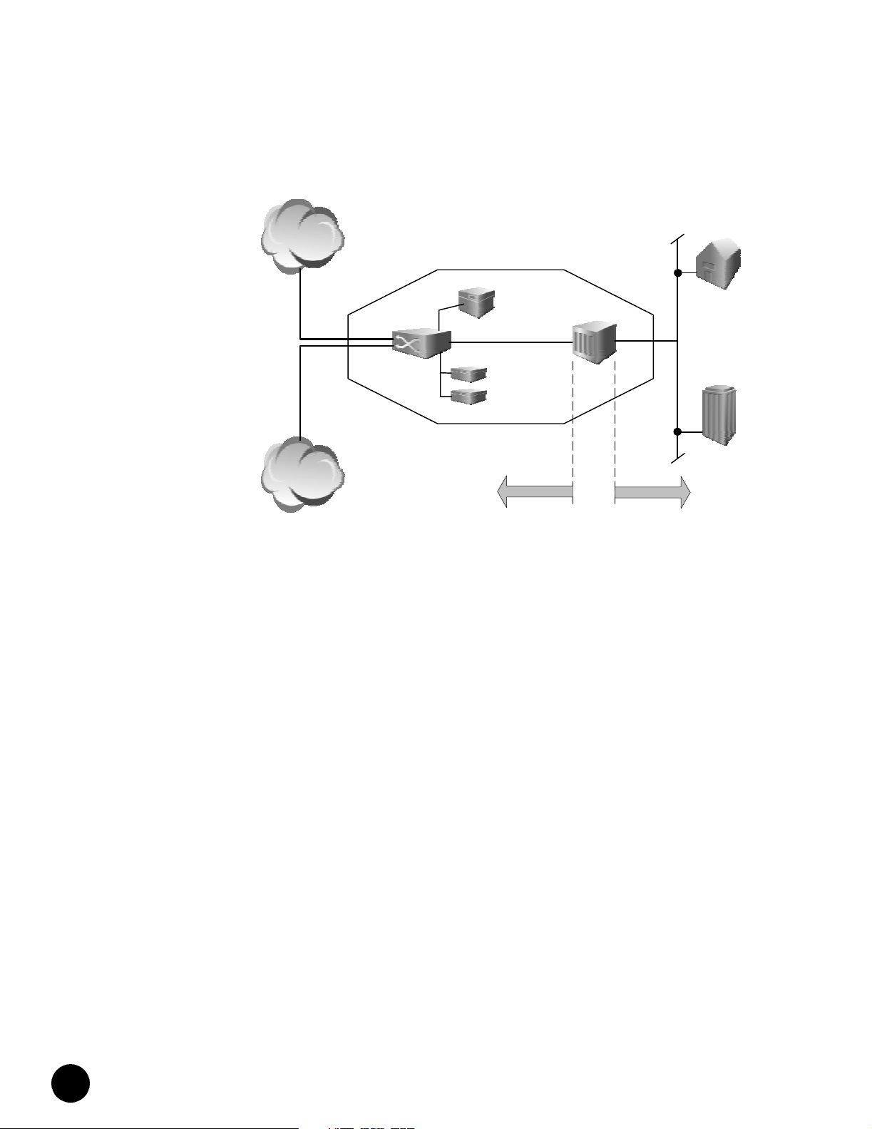
System Description
The JUNOSg software runs on the G10 cable modem termination system (CMTS) and
provides both IP routing (Layer 3) and IEEE 802.1 bridging (Layer 2), as well as software for
interface, network, cable services, and chassis management. The G10 CMTS manages
Internet voice and data. It functions as the interface between the service networks—Internet,
Public Switched Telephone Network (PSTN)—and the hybrid fiber/coax (HFC) network of
subscribers, as shown in Figure 1 on page 4. This is the “last mile” of broadband service, with
the CMTS typically located in the cable headend or distribution hub. It is targeted at the
following data and voice aggregation applications:
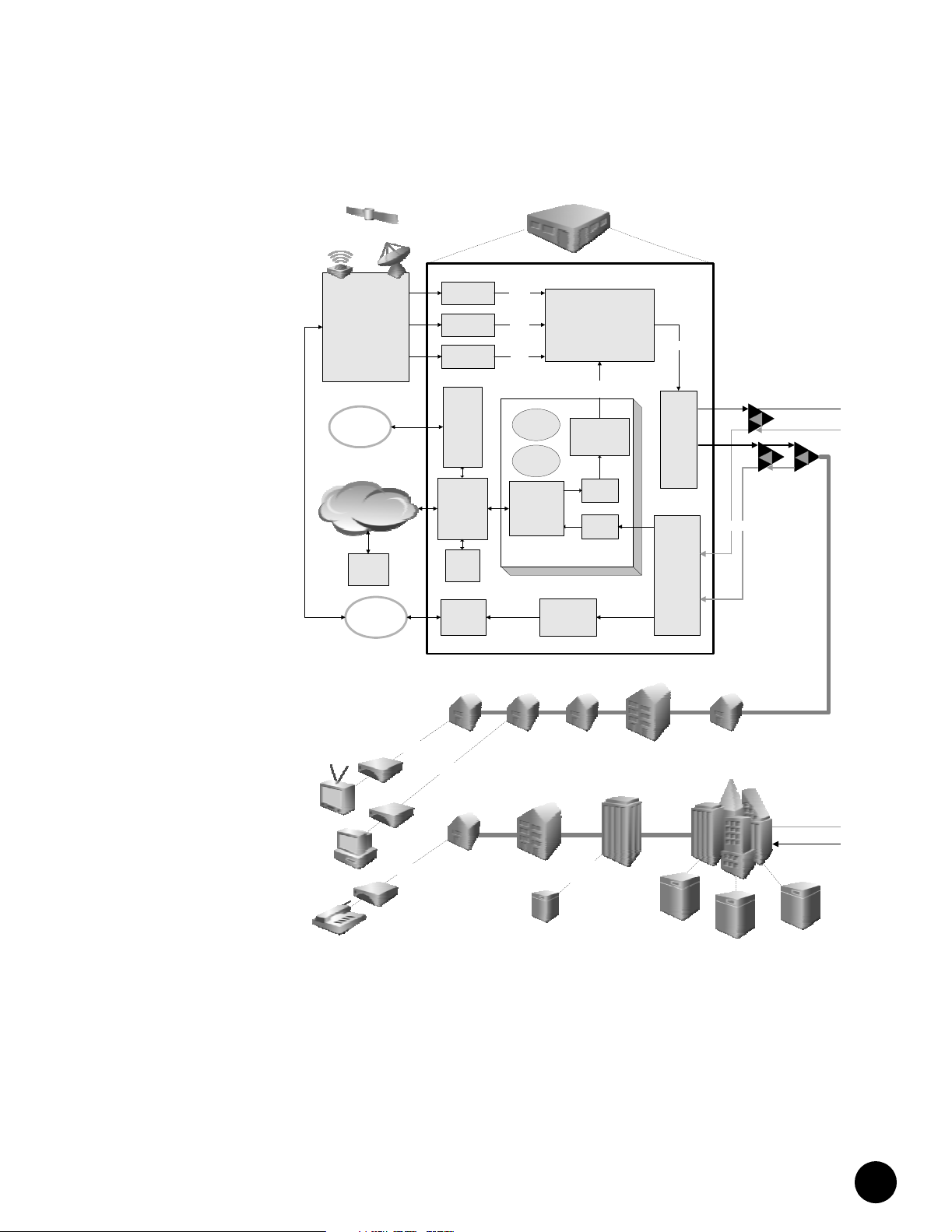
Figure 2 on page 5 illustrates a typical cable headend architecture.
! System Description on page 3
! Field-Replaceable Units (FRUs) on page 6
! G10 CMTS Features and Functions on page 7
! G10 CMTS Components on page 8
! G10 CMTS Management on page 10
! G10 CMTS Hardware Overview on page 10
! Large CATV hub sites—DOCSIS multiservice, residential, and commercial IP network
access over HFC networks maintained by cable television (CATV) multiple service
operators (MSOs) needing enhanced integrated data, voice, and video in large
metropolitan areas.
! Small CATV hub sites—Smaller hub sites aggregated over metropolitan fiber rings
supporting Gigabit Ethernet.
•
•
•
•
•
•
•
•
•
•
•
•
•
•
•
•
•
•
•
•
•
•
•
•
•
•
•
•
•
•
•
•
•
•
•
•
•
•
•
•
•
•
•
•
•
•
•
•
System Overview
3
Page 20
System Description
•
Figure 1: Typical CMTS Location
•
•
•
•
•
•
•
•
•
•
•
•
•
•
•
•
•
•
•
•
•
•
•
•
•
•
•
•
•
•
•
•
•
•
•
•
•
•
•
•
•
•
•
•
•
•
•
•
•
•
•
•
•
•
•
•
•
Internet
Backbone
PSTN
Switch/
Router
Cable Headend
or
Distribution Hub
Network
Management
Video
Servers
Network Side
Interface
Subscribers
CMTS
Hybrid Fiber/Coax
Network
JUNOSg 3.0 G10 CMTS Hardware Guide
4
Page 21
System Description
b
U
Figure 2: Headend Architecture
Broadcast Channels:
Satellite, Fiber,
Cable,
Others
PSTN
Backbone
Network
Remote
Server
Facility
ATM
Telephony
Video
Upconverter
Upconverter
Upconverter
Remote
Dial-Up
Access
Server
Backbone
Transport
Adapter,
Switch,
LAN, or
Hub
Local
Server
Facility
Interactive
Cable
Gateway
Data
Analog
Video
Digital
Video
Other
Operations
System
Support
Security &
Access
Control
Network
Termination
Upconverters
CMTS
Audio / Video
Demod
High-speed
Data
Combiner
QAM
Data
Mod
Demod
Head End
54-750 MHz
Splitter
Combiner
and
Signal
Router
5-42 MHz
E/O O/E
Coax Cable
•
•
•
•
•
•
•
•
•
•
•
•
•
•
•
•
•
•
•
•
•
•
•
•
•
•
Fi
•
•
•
•
•
•
•
•
•
•
•
•
•
•
•
•
•
•
•
•
•
•
•
•
•
•
•
•
•
•
•
•
System Overview
5
Page 22

Field-Replaceable Units (FRUs)
•
Field-Replaceable Units (FRUs)
•
•
•
•
•
•
•
•
•
•
•
•
•
•
•
•
•
•
•
•
•
•
•
•
•
•
•
•
•
•
•
•
•
•
•
•
•
•
•
•
•
•
•
•
•
•
•
•
•
•
•
•
•
•
•
•
•
Field-replaceable units (FRUs) are CMTS components that can be replaced at the customer
site. Replacing FRUs requires minimal CMTS downtime. A FRU can be ordered as a separate
unit for replacement into the CMTS or for stocking spare parts.
Following is an alphabetical list of G10 CMTS FRUs. See “G10 CMTS Hardware Overview” on
page 10 for a description of each FRU.
! AC power supply
! AC power tra nsi tio n mo dule
! Air management module
! Air management panel
! CCM Access Module
! Chassis
! Chassis Control Module
! DOCSIS Module
! DC power supply
! DC power transition module
! Front fan tray
! GBIC module
! Hard Disk Module
! HFC Connector Module
! NIC Module
! NIC Access Module
! NIC Access Module cable
! Power supply filler panel
! Rear fan tray
! Switched I/O Module (SIM)
JUNOSg 3.0 G10 CMTS Hardware Guide
6
Page 23

G10 CMTS Features and Functions
G10 CMTS Features and Functions
The G10 CMTS provides true multiservice support, including the ability to simultaneously
support DOCSIS IP services and VoIP services.
Functional Overview
The G10 CMTS is usually connected directly to a Gigabit-class core router that is part of a
multiple system operator’s (MSO) metropolitan core network. It receives network-side packet
streams originating from the Internet, Media Gateways or video servers, then processes them
into DOCSIS-compatible digital signals (MPEG) that are modulated onto an RF carrier for
transmission downstream over the HFC network to the subscribers’ cable modems.
Upstream signals consist of protocol data units (PDUs) in data bursts from the cable modems.
The G10 CMTS uses advanced scheduling algorithms to optimize the timing of these
transmissions. The packets are processed to recover the payload data, then routed, as IP
packets, to the appropriate destinations through the network-side interface.
The G10 CMTS’s high capacity of up to 32 downstream and 128 upstream interfaces and
other innovative features are provided by the Broadband Cable Processor ASIC
(application-specific integrated circuit).
Broadband Cable Processor ASIC
The Broadband Cable Processor ASIC provides all-digital processing of the return path. This,
plus advanced noise cancellation and equalization algorithms, enables modulation rates
beyond QPSK and allows traditionally problematic frequency ranges of the upstream
spectrum to be utilized. All-digital processing also accommodates full spectrum analysis by
capturing statistics of the upstream band in real time.
The Broadband Cable Processor ASIC incorporates key DOCSIS MAC (media access control)
functions such as concatenation, fragmentation, encryption, and decryption. Accelerating
these functions in hardware provides a high-performance, scalable CMTS solution that can
process thousands of simultaneous DOCSIS service flows.
Advanced timing and digital signal processing algorithms allow more efficient use of the
RF spectrum, resulting in increased channel capacity.
•
•
•
•
•
•
•
•
•
•
•
•
•
•
•
•
•
•
•
•
•
•
•
•
•
•
•
•
•
•
•
•
•
•
•
•
•
•
•
•
•
•
•
•
•
•
•
•
•
•
•
•
•
•
•
•
•
•
System Overview
7
Page 24

G10 CMTS Components
•
G10 CMTS Components
•
•
•
•
•
•
•
•
•
•
•
•
•
•
•
•
•
•
•
•
•
•
•
•
•
•
•
•
•
•
•
•
•
•
•
•
•
•
•
•
•
•
•
•
•
•
•
•
•
•
•
•
•
•
•
•
•
The G10 CMTS chassis employs front and rear modules that connect through a midplane.
Most of the cable connections are available in the rear of the unit. Following is a list of the
primary modules of the G10 CMTS:
! NIC Module—Provides Ethernet switching functionality for upstream and downstream
traffic and for the Fast Ethernet interfaces. Houses two Gigabit Ethernet ports with
Gigabit Interface Converters (GBICs).
! NIC Access Module—Fans out the Ethernet signals to individual 10/100Base-T lines,
which route to the HFC Connector Modules or Switched I/O Modules. A version of the
chassis provides internal Ethernet wiring between the NIC Modules and the DOCSIS
Modules.
! DOCSIS Module—Performs all data path processing functions, including Layer 2 bridging
and Layer 3 forwarding. Processes IP data into DOCSIS packets. Converts and modulates
data for RF transmission. Reverses these processes for upstream data.
! HFC Connector Module—Provides cable interfaces for a DOCSIS Module. Contains the
Fast Ethernet connectors for network-side data and the F-connectors for the HFC
cabling.
! Switched I/O Module—Provides the same functions as an HFC Connector Module, but
provides four additional upstream F-connectors for the HFC cabling.
! Chassis Control Module—Provides the management interface and runs the Routing
Engine software. Controls redundant protection functions and supplies software images
to all DOCSIS Modules. Runs the Simple Network Management Protocol (SNMP) agent
and environmental monitoring.
! Hard Disk Module—Contains the system nonvolatile memory implemented as a hard
disk. This module is installed opposite the Chassis Control Module.
The G10 CMTS relays traffic between DOCSIS RF interfaces, on which the cable modems
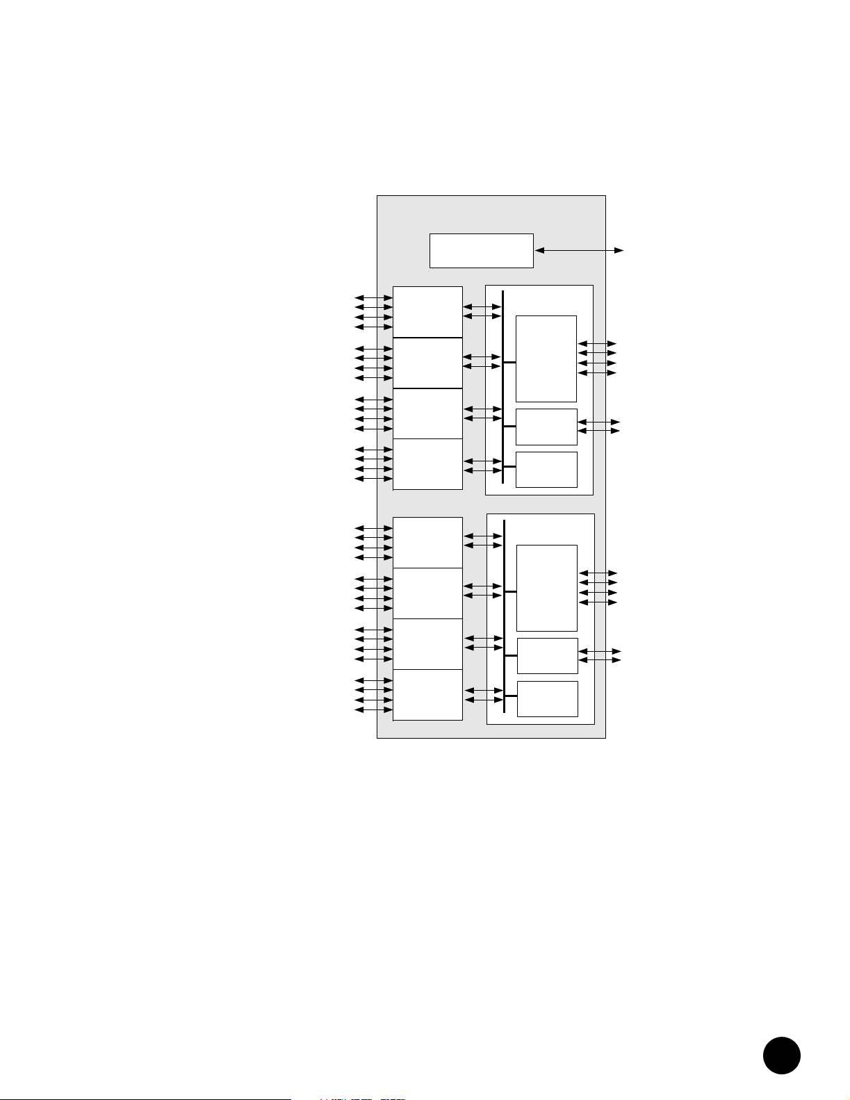
reside, and the network-side interfaces (Fast Ethernet and Gigabit Ethernet). Figure 3 on
page 9 illustrates the relationship between the primary modules in the chassis.
Each DOCSIS Module can support up to four cable interfaces, where a cable interface (MAC
domain) contains at least one downstream interface and one upstream interface. Each NIC
Module supports two Gigabit Ethernet interfaces and four Fast Ethernet interfaces. The
Chassis Control Module provides an out-of-band Fast Ethernet management interface.
See the JUNOSg Software Configuration Guide: Interfaces, Cable, Policy, and Routing and Routing
Protocols for more information on interfaces.
JUNOSg 3.0 G10 CMTS Hardware Guide
8
Page 25
G10 CMTS Components
t
Figure 3: G10 CMTS Components and Interfaces
32 Cable
Interfaces
ca-0/1/0
ca-0/1/1
ca-0/1/2
ca-0/1/3
ca-0/2/0
ca-0/2/1
ca-0/2/2
Domain A
Domain B
ca-0/2/3
ca-0/3/0
ca-0/3/1
ca-0/3/2
ca-0/3/3
ca-0/4/0
ca-0/4/1
ca-0/4/2
ca-0/4/3
ca-0/10/0
ca-0/10/1
ca-0/10/2
ca-0/10/3
ca-0/11/0
ca-0/11/1
ca-0/11/2
ca-0/11/3
ca-0/12/0
ca-0/12/1
ca-0/12/2
ca-0/12/3
ca-0/13/0
ca-0/13/1
ca-0/13/2
ca-0/13/3
DOCSIS
Module
DOCSIS
Module
DOCSIS
Module
DOCSIS
Module
DOCSIS
Module
DOCSIS
Module
DOCSIS
Module
DOCSIS
Module
G10 CMTS
Chassis Control
Module (Slot 6)
NIC Module &
NIC Access Module
3x Octal
Fast Ethernet
Switch Ports
2x Gigabit
Ethernet
Switch Ports
Switch
Element
NIC Module &
NIC Access Module
3x Octal
Fast Ethernet
Switch Ports
2x Gigabit
Ethernet
Switch Ports
Switch
Element
Management Por
fxp0
fx-0/5/0
fx-0/5/1
fx-0/5/2
fx-0/5/3
gx-0/5/0
gx-0/5/1
fx-0/9/0
fx-0/9/1
fx-0/9/2
fx-0/9/3
gx-0/9/0
gx-0/9/1
•
•
•
•
•
•
•
•
•
•
•
•
•
•
•
•
•
•
•
•
•
•
•
•
•
•
•
•
•
•
•
•
•
•
•
•
•
•
•
•
•
•
•
•
•
•
•
•
•
•
•
•
•
•
•
•
•
•
System Overview
9
Page 26

G10 CMTS Management
•
G10 CMTS Management
•
•
•
•
•
•
•
•
•
•
•
•
•
•
•
•
•
•
•
G10 CMTS Hardware Overview
•
•
•
•
•
•
•
•
•
•
•
•
•
•
•
•
•
•
•
•
•
•
•
•
•
•
•
•
•
•
•
•
•
•
•
•
•
•
The G10 CMTS supports the following system management applications and tools:
! Command-Line Interface (CLI)—The CLI provides the most comprehensive controls and
! SNMP—The CMTS can interact with SNMPv2c and SNMPv3-based Network
! ServiceGuard Management System – This optional advanced diagnostics application
This section provides an overview of the modules and various hardware components of the
G10 CMTS and where they reside within the chassis. This overview presents material that is
specific to the installation and configuration of the G10 CMTS.
Figure 4 on page 11 illustrates a front view of a fully configured chassis. Figure 5 on page 12
illustrates a front view of a partially configured chassis in which DOCSIS Modules, a Chassis
Control Module (CCM), a Network Interface Card (NIC) Module, power supplies, air
management modules, and power supply filler panels have been removed. Figure 6 on
page 13 illustrates a rear view of a fully configured chassis that uses the AC power transition
module and HFC Connector Modules (see Figure 39 on page 122 for an illustration of the DC
power transition module). Figure 7 on page 14 illustrates the rear view of the partially
configured chassis in which HFC Connector Modules, a Hard Disk Module, a NIC Access
Module, and air management panels have been removed. Figure 8 on page 15 provides a top
view of the chassis midplane showing the slot numbering and the location of each module.
is instrumental for installation, configuration, troubleshooting, and upgrade tasks.
Management Systems using DOCSIS 1.0 and DOCSIS 1.1 MIBs and enterprise MIBs.
Events can conditionally be reported as system log messages or SNMP traps.
with a Java GUI provides a rendition of a spectrum analyzer for acquiring data on
upstream transmission cable performance. It incorporates an integrated Impairment
Identification tool that allows for unattended monitoring of statistics to characterize
compromised performance to a potential cause (such as impulse or burst noise, narrow
band ingress, or microreflections).
JUNOSg 3.0 G10 CMTS Hardware Guide
10
Page 27
G10 CMTS Hardware Overview
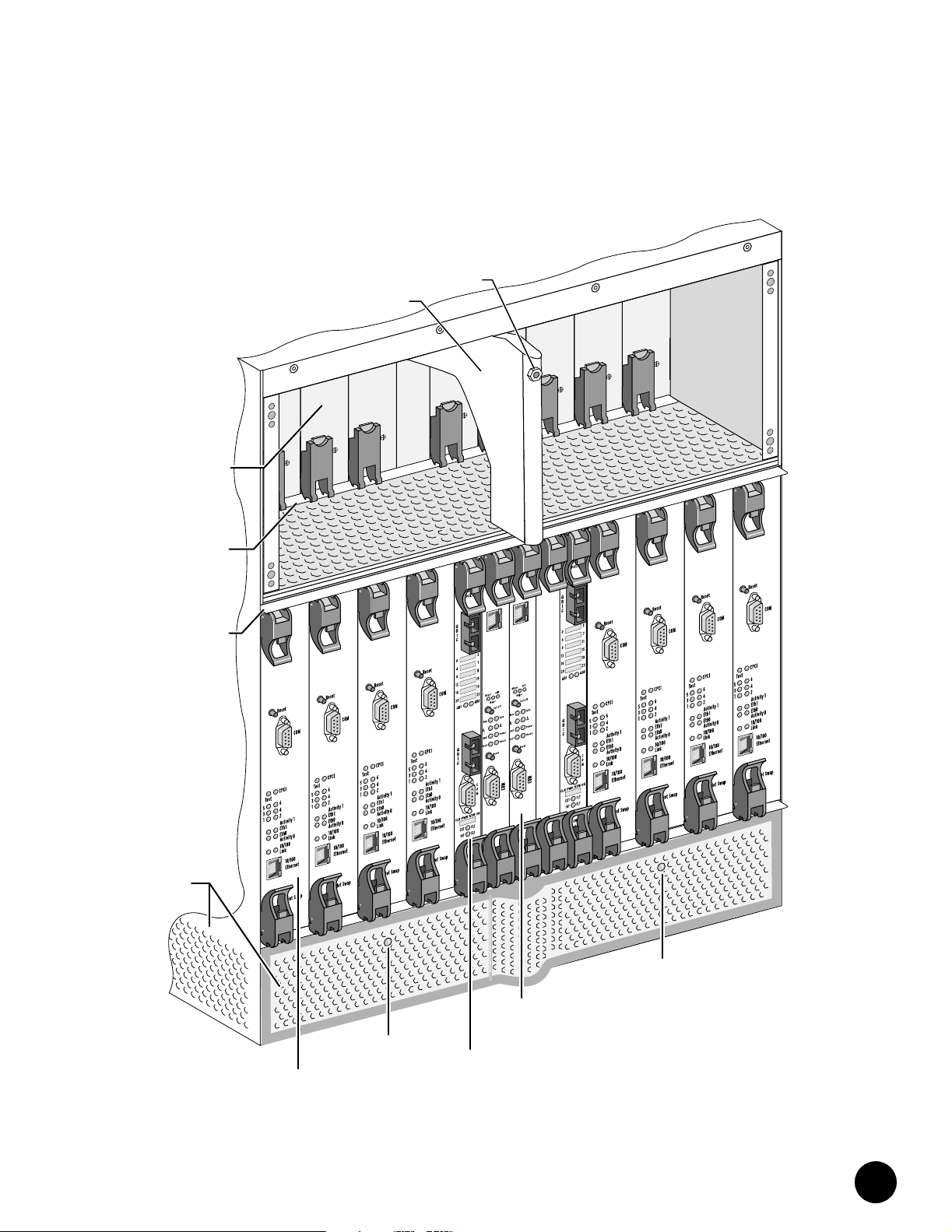
Figure 4: Front View of Fully Configured Chassis
Cable
Guide
Power
Power
Power
Fa
Fa
ult
Fault
ult
Power
Supply
Power
Supply
Ejector
Rail
Module
Ejector
Rail
Air
Intake
Front Fan
Tray LED
DOCSIS
Module
ESD
Strap
Jack
er
w
Po
Fault
Module
NIC
er
Pow
lt
u
Fa
Eth0
2
1
Chassis
Control
Module
•
•
•
•
•
er
Pow
lt
er
Pow
er
Pow
Fa
Fa
lt
u
Fau
lt
u
•
•
•
•
•
•
•
•
•
•
•
•
•
•
•
•
•
•
•
•
•
0
h
t
E
•
•
•
•
•
2
1
•
•
•
•
•
•
•
•
•
•
•
•
•
•
•
Front Fan
Tray L E D
•
•
•
•
•
•
•
•
•
•
•
•
System Overview
11
Page 28
G10 CMTS Hardware Overview
•
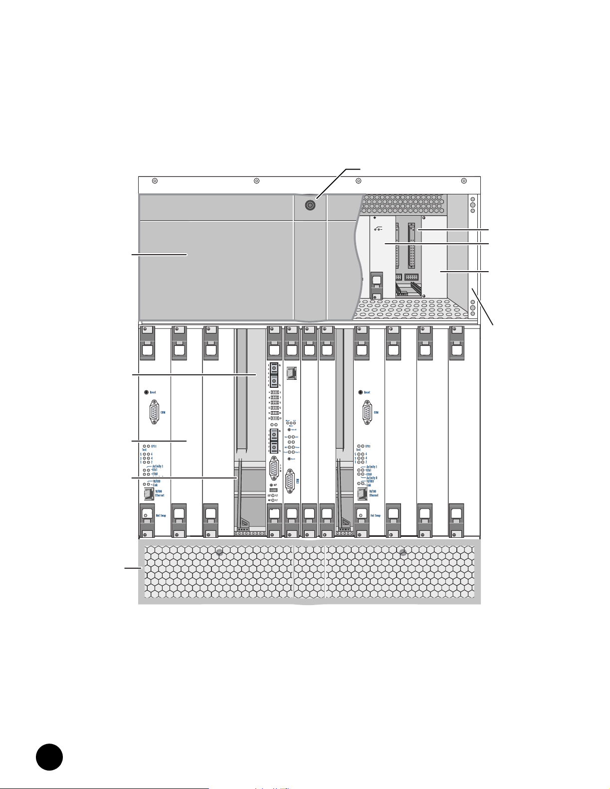
Figure 5: Front View of Partially Configured Chassis
•
•
•
•
•
•
•
•
•
•
•
•
•
Power
Supply
Faceplate
Power
Power
Fault
Power
Fault
•
•
•
•
•
•
•
•
•
•
•
Midplane
•
•
•
•
•
•
Management
Air
Module
•
•
•
•
Card
Guide
•
•
•
•
•
•
•
•
Air
Intake
Faceplate
•
•
•
•
•
•
•
•
•
•
•
•
•
•
•
ESD
Strap
Jack
Power
Power
Fault
Power
Fault
Fault
Power
Power
Fault
Fault
Power
Fault
Supply
Bay
Power
Supply
Power
Supply
Filler
Panel
Power
Supply
Faceplate
Clip
JUNOSg 3.0 G10 CMTS Hardware Guide
12
Page 29
G10 CMTS Hardware Overview
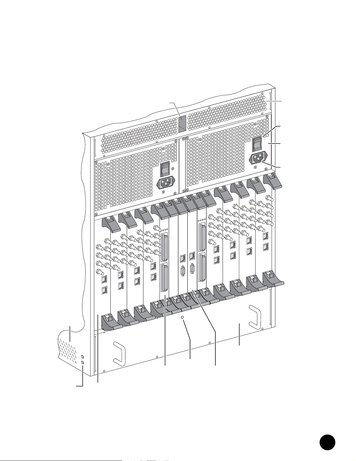
Figure 6: Rear View of Fully Configured Chassis
Channel
S 0
D
0
0
S
D
S 0
D
US 0
S 1
0
US
1
US 1
2
2
US
US 3
Eth0
Eth1
D
DS 1
1
US
S 2
D
S 2
D
2
US
S 3
D
DS 3
US 3
Eth0
Eth1
US
US 0
DS 1
US 1
US 1
S 2
D
US 2
2
US
DS 3
US 3
US 3
Eth0
Eth0
Eth1
Eth1
Air
Intake
Chassis
Ground
Nuts
HFC
Connector
Module
Cable
OPERATIONAL
POWER
DS 0
1
S 1
D
S 2
D
S 3
D
NIC
Access
Module
INT FAULT
2
EXT FAULT
Eth
Eth
C
O
C
M
O
M
Rear Fan
Tray LED
OPERATIONAL
INT FAULT
POWER
1
2
EXT FAULT
0
US
1
US
US 2
US 3
Eth0
Eth1
CCM
Access
Module
S 0
D
S 1
D
S 2
D
DS 3
S 0
D
US 0
DS 1
1
US
S 2
D
2
US
DS 3
US 3
Eth0
Eth1
Rear Fan
Tray
•
•
•
•
•
•
Air
Exhaust
•
•
•
•
AC Power
Switch
AC Power
Transition
Module
AC Power
Receptacle
•
•
•
•
•
•
•
•
•
•
DS 0
S 0
D
0
US
S 1
US 0
US 1
2
US
US 3
Eth0
Eth1
D
1
S
D
US 1
2
S
D
DS 2
US 2
S 3
D
S 3
D
US 3
Eth0
Eth1
•
•
•
•
•
•
•
•
•
•
•
•
•
•
•
•
•
•
•
•
•
•
•
•
•
•
•
•
•
•
•
•
•
•
•
•
•
•
System Overview
13
Page 30
G10 CMTS Hardware Overview
•
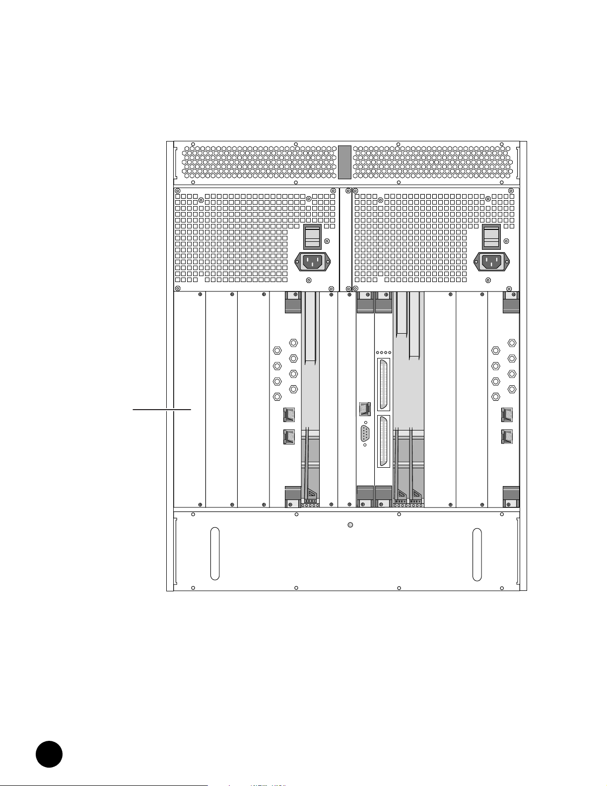
Figure 7: Rear View of Partially Configured Chassis
•
•
•
•
•
•
•
•
•
•
•
•
•
•
•
•
•
•
•
•
•
•
•
•
•
•
•
•
Management
Air
Panel
•
•
•
•
•
•
•
•
•
•
•
•
•
•
•
•
•
•
•
•
•
•
•
•
•
•
•
•
•
OPERATIONAL
EXT FAULT
DS 0
US 0
DS 1
US 1
DS 2
US 2
DS 3
US 3
Eth0
Eth1
INT FAULT
POWER
1
Eth
C
O
M
2
DS 0
US 0
DS 1
US 1
DS 2
US 2
DS 3
US 3
Eth0
Eth1
JUNOSg 3.0 G10 CMTS Hardware Guide
14
Page 31

G10 CMTS Hardware Overview
Figure 8: Chassis Top View Showing Midplane Slot Numbering
Rear
HFC Connector Module or
SIM
HFC Connector Module or
SIM
HFC Connector Module or
SIM
HFC Connector Module or
SIM
NIC Access Module
Hard Disk Module
Hard Disk Module
NIC Access Module
HFC Connector Module or
SIM
HFC Connector Module or
SIM
HFC Connector Module or
SIM
HFC Connector Module or
SIM
13
12
11
10
9
8
7
6
5
4
3
2
1
Midplane
with logical slot numbers
Slots 1 through 6 reside in domain A. Slots 7 and 9 through
13 reside in domain B.
DOCSIS Module
DOCSIS Module
DOCSIS Module
DOCSIS Module
NIC Module
Chassis Control Module
Chassis Control Module
NIC Module
DOCSIS Module
DOCSIS Module
DOCSIS Module
DOCSIS Module
Front
•
•
•
•
•
•
•
•
•
•
•
•
•
•
•
•
•
•
•
•
•
•
•
•
•
•
•
•
•
•
•
•
•
•
•
•
•
•
•
•
•
•
•
•
•
•
•
•
•
•
•
•
•
•
•
•
•
•
System Overview
15
Page 32

G10 CMTS Hardware Overview
•
Following is a brief explanation of each feature shown in Figure 4 through Figure 7:
•
•
•
Front Features ! DOCSIS Module—Module that contains the Broadband Cable Processor ASIC and resides
between the network-side interface (NSI) and the hybrid fiber/coax (HFC) interface.
•
•
•
! NIC Module—Module that provides the Gigabit Ethernet interface and the Fast Ethernet
switching functions for the network-side interface.
•
•
! Chassis Control Module—Module that performs management and monitoring functions.
•
•
•
! Module ejector rail—Rail into which a module’s ejector tabs fit when a module is
installed in a slot.
•
•
! ESD strap connector—Location where you can insert an ESD ground strap.
•
•
•
! Air intake—Slotted openings along the front (removable) and sides of the chassis where
air is drawn into the chassis for cooling the installed modules and power supplies.
•
•
! Air intake faceplate—Slotted removable panel that covers the two front fan trays.
•
•
! Air intake faceplate clip—Retainer clip used to mount the air intake faceplate.
•
•
! Front fan tray—Fan assembly that forces air upward through the front of the chassis.
•
•
! Front fan tray LED—LED that shows the status of the front fan tray.
•
•
•
! Power supply ejector rail—Rail into which the power supply ejector tabs fit when a
power supply is installed in a bay.
•
•
! Midplane—Passive electrical interconnecting device for all modules in the chassis.
•
•
•
! Air management module—Module installed in an unused module slot to redirect the air
flow through the chassis and to reduce EMI emissions.
•
•
•
! Card guide—Used to align a module or power supply while it is being inserted into its
slot or bay.
•
•
•
! Power supply—Converts AC or DC power supplied through the power transition modules
into the DC voltages required by the modules.
•
•
•
! Power supply faceplate—Panel along the top of the chassis that covers the power
supplies.
•
•
! Power supply faceplate clip—Retainer clip used to mount the power supply faceplate.
•
•
•
! Power supply bay—Chassis bay in which a single hot-swappable power supply is
inserted.
•
•
! Power supply filler panel—Panel covering an empty power supply bay.
•
•
•
! Cable channel—Channel through the top of the chassis that is used to route the network
cables from the rear of the chassis to the front.
•
•
•
! Cable guide—Guide used to route the network cables between the cable channel and the
lower opening in the power supply faceplate.
•
•
•
JUNOSg 3.0 G10 CMTS Hardware Guide
16
Page 33

G10 CMTS Hardware Overview
Rear Features ! HFC Connector Module—Module that functions as the DOCSIS Module’s physical access
to both the NSI and the HFC interfaces on the rear of the chassis.
! Switched I/O Module—Provides the same functions as an HFC Connector Module, but
provides four additional upstream F-connectors for the HFC cabling.
! NIC Access Module—Module that provides the network connections between the NIC
Modules and the HFC Connector Modules.
! Hard Disk Module—Contains the system nonvolatile memory implemented as a hard
disk. This module is installed opposite the Chassis Control Module.
! Rear fan tray—Fan assembly that forces air upward through the rear of the chassis.
! Rear fan tray LED—LED that shows the status of the rear fan tray.
! Air management panel—Panel installed over an unused module slot to redirect the air
flow through the chassis and to reduce EMI emissions.
! Air exhaust—Panel along the top and rear of the chassis where air is expelled from the
chassis for cooling.
! AC power transition module—Rear module that distributes the externally supplied AC
power to the midplane.
! AC power receptacle—AC power cord receptacle on AC power transition module.
! AC power switch—AC power On/Off switch that resides on the AC power transition
module.
! DC power transition module—Rear module that distributes the externally supplied DC
power to the midplane.
! DC power receptacle—DC power cord terminal block on DC power transition module.
! Chassis ground nuts—Location where the earth ground connection to the chassis is
made.
•
•
•
•
•
•
•
•
•
•
•
•
•
•
•
•
•
•
•
•
•
•
•
•
•
•
•
•
•
•
•
•
•
•
•
•
•
•
•
•
•
•
•
•
•
•
•
•
•
•
•
•
•
•
•
•
•
•
System Overview
17
Page 34

G10 CMTS Hardware Overview
•
•
•
•
•
•
•
•
•
•
•
•
•
•
•
•
•
•
•
•
•
•
•
•
•
•
•
•
•
•
•
•
•
•
•
•
•
•
•
•
•
•
•
•
•
•
•
•
•
•
•
•
•
•
•
•
•
•
JUNOSg 3.0 G10 CMTS Hardware Guide
18
Page 35

Chapter 2
Hardware Component Overview
This chapter provides an overview of the G10 CMTS hardware components:
! Chassis on page 19
! DOCSIS Module on page 29
! Chassis Control Module on page 37
! NIC Module on page 42
! Chassis Rear Modules on page 48
Chassis
This section discusses the following characteristics of the G10 CMTS chassis components:
! Physical Characteristics on page 20
! Card Cage and Midplane on page 21
! Chassis Versions on page 25
! Power Supplies on page 26
! Power Transition Modules on page 28
! Cooling and Fans on page 29
The chassis is a rack-mountable, 19-inch wide, 13 U high housing that contains the modules,
power supplies and fans. The chassis accepts CompactPCI standard modules that conform to
dimensions specified in IEEE Standard 1101.1-1998. The use of a midplane as the
interconnecting device allows modules to be installed from both the front and rear of the
chassis.
See Figure 4 on page 11 and Figure 6 on page 13 for illustrations of the front and rear of a
fully populated chassis.
•
•
•
•
•
•
•
•
•
•
•
•
•
•
•
•
•
•
•
•
•
•
•
•
•
•
•
•
•
•
•
•
•
•
•
•
•
•
•
•
•
•
•
•
•
•
•
•
Hardware Component Overview
19
Page 36

Chassis
•
•
•
•
•
•
•
•
•
•
•
•
•
•
•
•
•
•
•
•
•
•
•
•
•
•
•
•
•
•
•
•
•
Physical Characteristics
•
•
•
•
•
•
•
•
•
•
•
•
•
•
•
Table 1: Chassis Physical Specifications
•
•
•
•
•
•
•
•
•
•
The major components of the G10 CMTS chassis are listed below and discussed in detail in
the following chapters.
! DOCSIS Module—Up to eight modules, depending on planned customer capacity.
! HFC Connector Module—Up to eight modules, one for each DOCSIS Module.
You cannot use an HFC Connector Module in a version 2
chassis if you are also using a NIC Module.
! SIM—Up to eight modules, one for each DOCSIS Module. The SIM can be used with a
version 1 or version 2 chassis.
! Chassis Control Module—One module.
! Hard Disk Module—One module.
! NIC Module—One or two modules; one module per four DOCSIS Modules.
! NIC Access Module—One or two modules, one for each NIC Module.
! Power supply—10 units, AC or DC.
! Power transition module—Two modules, AC or DC models.
! Fan—Two front trays and one rear tray housing a total of 18 fans.
Chassis physical and environmental specifications are provided in Table 1 on page 20 and
Ta b l e 2 o n pa g e 2 1 .
The G10 CMTS chassis is constructed of plated sheet metal. It fits into a 19-inch equipment
rack that complies with EIA standard RS-310-C. You can install the chassis into a 23- inch EIA
rack by attaching additional mounting brackets to the sides of the chassis. Additional rail and
bracket mounting holes are provided to support installation into nonstandard racks.
Threaded nuts for chassis ground are located on the lower right side of the chassis near the
rear. One ESD jack for wrist straps is located in the front upper center (see Figure 4 on
page 11).
Specification Value
Height 578 mm (22.8 in., 13 U)
Width 480 mm (18.9 in.), excluding mounting brackets
Depth 483 mm (19.0 in.)
Weight 36 kg (80 lb) empty
64 kg (140 lb) fully populated
JUNOSg 3.0 G10 CMTS Hardware Guide
20
Page 37

Chassis
Table 2: Chassis Environmental Specifications
Specification Value
Ambient temperature range (operational) 0° to +40°C (0° to +104°F)
Ambient temperature range (nonoperational) –35° to +60°C (–31° to +140°F)
Altitude 60 m (197 ft.) below sea level to 1800 m (5,905 ft.)
Relative humidity 10% to 90% non-condensing
Vibration (operational) 5 Hz to 100 Hz and back to 5 Hz, at 0.1 g (0.1 oct/min)
Card Cage and Midplane
The card cage is the main section of the chassis that houses all the modules, which are based
on circuit cards. Card cage and midplane specifications are described in Table 3. The bays for
the power supplies and power transition modules sit above the card cage, and the bays for
the fans sit below it (see Figure 4 on page 11).
Table 3: Card Cage and Midplane Specifications
Specification Value
Standard module dimensions Module Face Plate
Midplane dimensions 487 mm (19.2 in.) height
Midplane card slots 13 slots spanning 21 connector columns
Module capacity
(each front and rear)
The midplane is the passive electrical interconnecting device for all modules in the chassis. It
complies with CompactPCI Specification 2.0 R3.0, Oct.1, 1999. Analogous to a backplane, the
midplane resides towards the middle of the chassis with connectors facing front and rear (see
Figure 8 on page 15).
The G10 CMTS does not use all connector columns on the midplane. The DOCSIS Modules,
HFC Connector Modules, and SIMs are an 8 horizontal pitch (HP), double-wide design
covering two columns. The Chassis Control Modules and Hard Disk Modules are a 4 HP,
single-wide design. Midplane slot 8 is not used. This is reflected in the slot numbering
scheme.
The midplane extends the width of the chassis and the height of the chassis minus the top
and bottom air chambers.
262 mm (10.3 in., 6 U) height
20 mm (0.8 in.) width, single-wide
40 mm (1.6 in.) width, double-wide
Module Circuit Card
233 mm (9.2 in.) height
340 mm (13.4 in.) depth - front modules
80 mm (3.2 in.) depth - rear modules
428 mm (16.8 in.) width
8 double-wide modules (16-slot equivalent)
4 single-wide modules
1 unused single-wide slot
•
•
•
•
•
•
•
•
•
•
•
•
•
•
•
•
•
•
•
•
•
•
•
•
•
•
•
•
•
•
•
•
•
•
•
•
•
•
•
•
•
•
•
•
•
•
•
•
•
•
•
•
•
•
•
•
•
•
Hardware Component Overview
21
Page 38

Chassis
•
•
•
•
•
•
•
•
•
Table 4: Midplane P1 – P5 Connectors
•
•
•
•
•
•
•
•
•
•
•
•
•
•
•
•
•
•
•
•
•
•
•
•
•
•
•
•
•
•
•
•
•
•
•
•
•
•
•
•
•
•
•
•
•
•
•
•
•
The modules in the card cage use the P1 through P5 connectors of the midplane (see Figure 9
on page 23). The power supplies use connectors PS1 through PS10. Fan trays and power
transition modules also connect to the midplane.
Connectors P3 through P5 provide the pass-through interconnection between the modules in
the front and rear of the chassis. Connectors P1 and P2 support the cPCI bus. The major
signals carried by the connectors are described in Table 4.
Connector Function
P1 and P2 cPCI bus
P3 I
P4 and P5 RF signals to HFC Connector Module or SIM
2
C bus
Ether net to /from HFC Connector Mo dule or SIM
Synchronization and reference clocks
Powe r a nd g roun d
IF signals from HFC Connector Module or SIM
JUNOSg 3.0 G10 CMTS Hardware Guide
22
Page 39

Chassis
s
s
s
n
s
Figure 9: Midplane—Front and Rear Views
PS1 PS2 PS3 PS4 PS5 PS6 PS7 PS8 PS9 PS10
12 34 5678910111213
P5
P4
P3
P2
P1
P5
P4
P3
Front View
Pwr Supply Domain A Pwr Supply Domain B
cPCI Bus Domain A
cPCI Bus Domain B
Rear View
Power
Supply
Connector
Fan
Connector
Power
Distributio
Connector
12345678910111213
Fan
Connector
•
•
•
•
•
•
•
•
•
•
•
•
•
•
•
•
•
•
•
•
•
•
•
•
•
•
•
•
•
•
•
•
•
•
•
•
•
•
•
•
•
•
•
•
•
•
•
•
•
•
•
•
•
•
•
•
•
•
Hardware Component Overview
23
Page 40

Chassis
•
•
•
•
•
•
Table 5: Midplane Configuration
•
•
•
•
•
•
•
•
•
•
•
•
•
•
•
•
•
•
•
•
•
•
•
•
•
•
•
•
•
•
•
•
•
•
•
•
•
•
•
•
•
•
•
•
•
•
•
•
•
•
•
•
The midplane is partitioned into domains A and B as described in Table 5. This is required by
the bus length restrictions stipulated in the cPCI specification. The power supplies and power
distribution panels are also separated into domains A and B.
Domain Slot Front of Midplane Rear of Midplane
A 1 DOCSIS Module HFC Connector Module or SIM
2 DOCSIS Module HFC Connector Module or SIM
3 DOCSIS Module HFC Connector Module or SIM
4 DOCSIS Module HFC Connector Module or SIM
5 NIC Module NIC Access Module
6 Chassis Control Module CCM Access Module
B 7 Chassis Control Module CCM Access Module
8Blank Blank
B 9 NIC Module NIC Access Module
10 DOCSIS Module HFC Connector Module or SIM
11 DOCSIS Module HFC Connector Module or SIM
12 DOCSIS Module HFC Connector Module or SIM
13 DOCSIS Module HFC Connector Module or SIM
Release 3.0 does not support Chassis Control Module
redundancy.
The division of the domains is between slots 6 and 7. Each domain includes up to four
DOCSIS Modules, a NIC Module, and a Chassis Control Module in the front, and up to four
HFC Connector Modules or SIMs, a NIC Access Module, and a Hard Disk Module in the rear.
The number of modules depends on your planned capacity.
The domains are bridged by the Chassis Control Module. Slots 6 and 7 are keyed to accept
only a Chassis Control Module in the front and a Hard Disk Module in the rear. Peripheral
interrupts, clocks, and bus arbitration signals are routed to these system slots. Continuity of
the bus across the midplane is accomplished by the two cPCI buses extending beyond their
system slots to connect with the system slot of the other domain, as shown in Figure 10 on
page 25. The electrical connection of the Chassis Control Module to both buses is controlled
by a PCI-to-PCI bridge in the module.
JUNOSg 3.0 G10 CMTS Hardware Guide
24
Page 41

Chassis
Figure 10: Midplane Domains
Domain B
Domain A
Comm
Channel
Host
DOCSIS Module
123456 7910111213
DOCSIS Module
DOCSIS Module
DOCSIS Module
NIC Module
Controller
Chassis Control Module
Midplane Slot Numbers
(front view)
Chassis Control Module
NIC Module
DOCSIS Module
DOCSIS Module
DOCSIS Module
DOCSIS Module
Chassis Versions
There are two versions of the chassis—version 1 and version 2. Version 2 provides all the
functions provided by version 1, but contains a new midplane that provides the following
features:
! Support for eight RF upstream ports from a SIM to its corresponding DOCSIS Module.
! Ethernet wiring between DOCSIS Modules and NIC Modules that eliminates the need for
external NIC Access Module cables.
When Ethernet wiring within the new midplane is used:
! You must install a NIC Access Module opposite each
installed NIC Module for proper Ethernet signal
termination.
! You must not connect NIC Access Module cables to
the NIC Access Module.
! Ability to read the chassis version with the show chassis hardware detail command.
•
•
•
•
•
•
•
•
•
•
•
•
•
•
•
•
•
•
•
•
•
•
•
•
•
•
•
•
•
•
•
•
•
•
•
•
•
•
•
•
•
•
•
•
•
•
•
•
•
•
•
•
•
•
•
•
•
•
Hardware Component Overview
25
Page 42

Chassis
•
Power Supplies
•
•
•
•
•
•
•
•
•
•
•
•
•
•
•
•
•
•
•
•
•
•
•
•
•
•
•
•
•
•
Table 6: Power Supply LEDs
•
•
•
•
•
•
•
•
•
•
•
•
•
•
•
•
•
•
•
•
•
•
•
•
•
•
•
Power supplies are available in either AC or DC input voltage models. You must specify a
model when ordering a G10 CMTS. The power supplies and the chassis are mechanically
keyed to ensure that the same types are used together.
If you order an AC version of the CMTS without power redundancy, the CMTS ships with five
AC power supplies installed in domain A. If you order the CMTS with power redundancy, the
CMTS ships with 10 AC power supplies installed. DC versions of the CMTS are always shipped
with 10 DC power supplies installed.
Power redundancy provides input power redundancy as well as N+1 power supply
redundancy. You must supply power from different circuits to domain A and domain B for
power redundancy protection. However, the VDC outputs of each power supply are available
to all chassis modules through the power bus in the midplane.
An AC power supply front panel is shown in Figure 11 on page 27. The power supplies are in
a standard 3 U housing with a 160 mm depth and a 40 mm front panel width. The power
supplies install from the front of the chassis (see Figure 4 on page 11) and plug into the PS1
through PS10 connectors on the midplane (see Figure 9 on page 23). Power supplies are
hot-swappable.
Since a power supply is half the depth of the other modules in the front of the card cage, the
power supplies sit recessed in the chassis bay. A removable faceplate installs over the front
opening.
The power supply front panel contains two indicator LEDs—POWER and FAULT. Table 6 on
page 26 explains the significance of these LEDs.
POWER FAULT Meaning
Green Not illuminated Normal operation
Green Red ! Over-temperature
! Over-current or over power
limit condition
Not illuminated Red Voltage input failure
Not illuminated Not illuminated ! Power supply not installed
correctly
! No input power and no DC
output from other power
supplies to illuminate FAULT
LED
If the power supply is operating in a degraded mode due to an increase in its temperature, a
warning event is generated (if enabled). If the temperature rises to the over-temperature
shutdown limit, the FAULT LED is illuminated and a critical event is generated (if enabled).
Temperatures above the over-temperature shutdown limit cause the power supply to shut
down. See the JUNOSg Software Configuration Guide: Interfaces, Cable, Policy, and Routing and
Routing Protocols for more information on event configuration.
JUNOSg 3.0 G10 CMTS Hardware Guide
26
Page 43

Chassis
Figure 11: AC Power Supply Front Panel
Input Range
100-240V
200W Hot Swap
A fully populated chassis requires a nominal 1500 watts from an external power source. The
components of the chassis require 1000 watts (maximum) from the power supplies. The
aggregate power output from all voltage levels is 200 watts per power supply. Other electrical
characteristics are provided in Table 7 on page 28.
The CMTS components do not consume their maximum
power at the same time. Therefore, the CMTS maximum
power requirement is less than the sum of the maximum
power consumed by each component installed in the
CMTS.
•
•
•
•
•
•
•
•
•
•
•
•
•
•
•
•
•
•
•
•
•
•
•
•
•
•
•
•
•
•
•
•
•
•
•
•
•
•
•
•
•
•
•
•
•
•
•
•
•
•
•
•
•
•
•
•
•
•
Hardware Component Overview
27
Page 44

Chassis
•
Table 7: Power Supply Specifications
•
•
•
•
•
•
•
•
•
•
•
•
•
•
•
•
•
•
•
•
•
•
•
•
•
•
•
Power Transition Modules
•
•
•
•
•
•
•
•
•
•
•
•
•
•
•
•
•
•
•
•
•
•
•
•
•
•
•
•
•
•
Power Supply
Type Input Voltage Input Current Rating
AC 90 to 240 VAC
47 to 63 Hz
DC –36 to –72 VDC 6.0 A Nom (–48 VDC) +5.0 VDC 25.0 A
2.5 A Nom (110 V, 70 percent efficiency) +5.0 VDC 25.0 A
Output
Vol ta g e
+3.3 VDC 35.0 A
+12.0 VDC 8.0 A
–12.0 VDC 1.5 A
+3.3 VDC 35.0 A
+12.0 VDC 8.0 A
–12.0 VDC 1.5 A
Maximum
Output Current
The +5.0 VDC and +3.3 VDC outputs supply a combined maximum of 175 W using load
sharing.
You cannot use a 250 watt AC power supply and a
200 watt AC power supply in the same G10 CMTS chassis.
The external power sources for the CMTS connect to the power transition modules. Two
power transition modules install from the rear of the chassis and plug into the midplane
opposite the power supplies in the front (see Figure 6 on page 13). The power transition
modules are provided for either AC or DC power sources, depending on how the chassis is
configured.
The outputs of the AC and DC power transition modules are wired differently within the
midplane. An AC power transition module only supports the five power supplies within its
domain. However, because the outputs of each DC power transition module are wired
together along the midplane, each DC power transition module supplies power to all 10 DC
power supplies in the chassis.
Full power redundancy consists of redundant power supplies, power transition modules, and
power sources. All G10 CMTS systems are shipped with two power transition modules
installed, one per domain, to implement power transition module redundancy. This also
facilitates power source redundancy. You must supply power from different circuits to each
power transition module to implement power source redundancy.
Each AC module has a double-pole rocker switch that serves as a power switch for the
chassis. The switch is recessed to prevent accidental activation.
The AC panel has a standard IEC 15-A receptacle with a three-prong male plug for connecting
to a power source. The DC panel has a 40-A terminal block with barrier guards for single lug
connections to the source and return.
JUNOSg 3.0 G10 CMTS Hardware Guide
28
Page 45

DOCSIS Module
Cooling and Fans
DOCSIS Module
The G10 CMTS has three fan trays. The trays install into the air intake chambers in the bottom
of the chassis. Two trays install from the front and one tray installs from the rear. The front
trays contain six large fans each and the rear tray contains six smaller fans. The total
maximum power consumption of the three fan trays is 165 watts.
Each tray has one LED. If a single fan fails, the LED illuminates red and a warning event is
generated (if enabled). If multiple fans fail, a critical event is generated (if enabled). See the
JUNOSg Software Configuration Guide: Interfaces, Cable, Policy, and Routing and Routing
Protocols for more information on event configuration.
The Chassis Control Module monitors the internal temperature of the chassis in multiple
locations. If the temperature is maintained between a lower and an upper threshold, the fans
continue to rotate at a nominal speed. If the temperature exceeds the upper threshold, the
speed of the fans and the value of the upper threshold are incrementally increased. Likewise,
if the temperature drops below the lower threshold, the speed of the fans and the value of the
lower threshold are incrementally decreased. This process continues until the temperature
and fan speed settle between the latest thresholds.
These temperature thresholds cannot be changed by a user. However, you can set
user-defined temperature thresholds by including the temperature-threshold statement at the
[edit chassis] hierarchy level (see the JUNOSg Software Configuration Guide: Getting Started
and System Management for more information).
The chassis directs the air flow upward through the card cage, then past the power supplies
and power transition modules. There is a 97-mm high air intake chamber with front and side
openings at the bottom of the chassis. Air exits through a 71-mm high chamber at the top of
the chassis through a rear opening and through the power transition modules in the rear.
The presence of the various modules is part of the air flow design. In a chassis that is not fully
populated, you must install air management modules, air management panels, and power
supply filler panels in all unused module slots to maintain proper air flow. You must also
install the power supply faceplate to ensure proper air flow.
The G10 CMTS must be installed in an open rack to ensure adequate air flow.
The DOCSIS Module contains the circuits, devices (including the Broadband Cable Processor
ASIC), and code that provide the core functionality and features of the G10 CMTS.
The DOCSIS Module connects with the HFC Connector Modules or SIMs in the rear of the
chassis through the midplane. This keeps the cabling in back of the chassis. See “HFC
Connector Module” on page 50 and “Switched I/O Module” on page 53 for more discussion.
Figure 12 on page 30 shows the DOCSIS Module front panel.
•
•
•
•
•
•
•
•
•
•
•
•
•
•
•
•
•
•
•
•
•
•
•
•
•
•
•
•
•
•
•
•
•
•
•
•
•
•
•
•
•
•
•
•
•
•
•
•
•
•
•
•
•
•
•
•
•
•
Hardware Component Overview
29
Page 46

DOCSIS Module
•
Figure 12: DOCSIS Module Front Panel
•
•
•
•
•
•
•
•
•
•
•
•
•
•
•
•
•
•
•
•
•
•
•
•
•
•
•
•
•
•
•
•
•
•
•
•
•
•
•
•
•
•
•
•
•
•
•
•
•
•
•
•
•
•
•
•
•
Hot Swap
JUNOSg 3.0 G10 CMTS Hardware Guide
30
Page 47

DOCSIS Module
Functional Characteristics
The DOCSIS Module is fully compliant with CompactPCI Specification 2.0 R3.0, Oct.1, 1999.
The module contains a 6 U (267 mm) x 340 mm card with an 8 HP (40 mm), double-wide
front panel. Physical dimension are provided in Table 8 on page 36. The module installs from
the front of the chassis and is hot-swappable.
Each DOCSIS Module has a companion HFC Connector Module or SIM on the back side of
the midplane (see Figure 8 on page 15). All network-side traffic and HFC-side traffic
transmitted and received by the DOCSIS Module passes through the midplane to and from
the HFC Connector Module or SIM. Thus, no external connections to the DOCSIS Module are
required from the front of the chassis for normal operation.
Downstream data flow comes to the DOCSIS Module from the HFC Connector Module or SIM
in the form of Internet data in IP packets. The module performs various processes described
in “Data Packet Processing” on page 32. The data is encapsulated first into DOCSIS frames,
then into an MPEG transport stream. The transport stream is modulated onto an RF signal for
downstream distribution to the cable modems.
The upstream data flow is contained in PDUs (protocol data units) of varying length
transmitted as TDMA bursts on specifically allocated frequencies. This process is controlled
by advanced timing algorithms.
The DOCSIS Module also has other innovations to achieve high levels of density and
performance. It combines the high-density Broadband Cable Processor ASIC with four
500 MHz MPC7410 processors for high-performance network edge processing in an
asymmetric multiprocessing architecture. The 60x system bus connecting the MPC7410
processors has a data rate of 8 Gbps. This module contains 384 MB of RAM, 128 KB of
NVRAM, and 1.5 MB of flash memory.
It runs DOCSIS MAC protocols, the scheduler, and all data path processing such as packet
filtering, rate-limiting, traffic shaping, and 802.1D bridging. The Broadband Cable Processor
ASIC provides hardware assist for the following functions: MAC protocol, scheduling,
concatenation, fragmentation, encryption and decryption, spectrum analysis, noise
cancellation, pre-equalization, and per-SID (Service Identifier) statistics.
The proprietary Broadband Cable Processor ASIC supports up to four downstream and eight
or 16 upstream interfaces (depending on the DOCSIS Module model). It enables the
implementation of QPSK and 16QAM modulation on upstream channels with very low
packet loss in the presence of noise. This allows tighter scheduling of packets, thereby
efficiently utilizing more of the RF spectrum. Downstream modulation uses 64QAM or
256QAM.
With up to eight DOCSIS Modules per chassis, the maximum interface capacity is
32 downstream interfaces and 128 upstream interfaces.
Figure 13 on page 32 shows a block diagram of the DOCSIS Module and Figure 14 on
page 33 shows the packet processing flow.
•
•
•
•
•
•
•
•
•
•
•
•
•
•
•
•
•
•
•
•
•
•
•
•
•
•
•
•
•
•
•
•
•
•
•
•
•
•
•
•
•
•
•
•
•
•
•
•
•
•
•
•
•
•
•
•
•
•
Hardware Component Overview
31
Page 48

DOCSIS Module
•
Figure 13: DOCSIS Module Block Diagram
•
•
•
•
•
•
•
•
•
•
•
•
•
•
•
•
•
Broadband Cable Processor
ASIC
•
•
•
•
•
•
•
•
•
•
•
•
•
•
•
Data Packet Processing
•
•
•
•
•
This section describes the major processing functions performed at the PHY, MAC, and
higher protocol layers for DOCSIS 1.1 and EuroDOCSIS 1.1 compliance. Figure 14 on page 33
illustrates these functions. See the DOCSIS specifications for more details.
•
•
•
•
•
•
•
•
•
•
•
•
•
•
•
•
•
•
•
•
Upconverter
Modem
Packet, Scheduling, and Management
Processing Devices
I2C
Dual PCI Bridge
Memory Controller
Bridge
Traffic
Port
100Base-T
cCPI Midplane
Traffic
Port
100Base-T
SDRAM
Flash
Memory
Timer &
NVRAM
Mgmt
Port
100Base-T
Security
Proc.
JUNOSg 3.0 G10 CMTS Hardware Guide
32
Page 49

DOCSIS Module
Figure 14: Packet Processing Layers
Management
Interface
CMTS
Management
Packet
Filtering
Downstream
Upstream
Classifier
Management/
Scheduler
Management/
Control
PMD Sublayer
DOCSIS Data
to/from HFC
Upconverter Modem
Higher Layer Functions
The DOCSIS Module provides the following higher layer functions:
! Packet filtering and forwarding—Filters Layer 2, Layer 3, Layer 4, and above based on
DOCSIS 1.1 filter functionality.
! CMTS management—SNMP, MIBs, and CLI (command-line interface).
! Network-side interface (NSI)—IP data and VoIP interfaces.
Higher Layers
MAC Layer
Packet Header
Suppression
PHY Layer
Higher Layer
Functions
Forwarding
Frame
Parser
Frame
Generator
MPEG Groomer
Network Layer
Protocols
De-encapsulator
Defragment
Deconcatenate
Decrypt
Encryption
DTC Sublayer
MPEG
VoIP
Data/IP
Downstream
Network-Side Interface
Upstream
•
•
•
•
•
•
•
•
•
•
•
•
•
•
•
•
•
•
•
•
•
•
•
•
•
•
•
•
•
•
•
•
•
•
•
•
•
•
•
•
•
•
•
•
•
•
•
•
•
•
•
•
•
•
•
•
•
•
Hardware Component Overview
33
Page 50

DOCSIS Module
•
MAC Layer Functions
•
•
•
•
•
•
•
•
•
•
•
•
•
•
•
•
•
•
•
•
•
•
•
•
•
•
Physical Layer Functions
•
•
•
•
•
•
•
•
•
•
•
•
•
•
•
•
•
•
•
•
•
•
•
•
•
•
•
•
•
•
•
The DOCSIS Module provides the following MAC layer functions:
! Classifier—Classifies upstream data frames into higher layer packet flows; classifies
downstream frames into corresponding service flows using service flow IDs (SFIDs).
! Frame generator—Encapsulates downstream packets into DOCSIS frames.
! Encryption—Encrypts downstream data frames in accordance with the DOCSIS Baseline
Privacy and Baseline Privacy Plus standards.
! Decryption—Decrypts upstream data.
! Fragmentation/concatenation—Reassembles upstream fragmented MAC frames and
deconcatenates concatenated MAC frames.
! Frame parser—Parses DOCSIS MAC header, identifies packet as data or management,
and routes accordingly. Verifies header checksum (HCS) and cyclical redundancy
checking (CRC).
! MAC management—Provides cable modem, service flow, and RF management
functions. Performs resource allocation scheduling of requests, service flows, QoS, and
other items. Handles cable modem and service flow admission control.
The DOCSIS Module provides the following physical layer functions:
! Downstream transmission convergence (DTC) sublayer:
! Manages the use of internal or external clock in MPEG transport stream; inserts
timestamp.
! Examines packets for DOCSIS PID (packet identifier) and MPEG null PID and
multiplexes queued data packets into available MPEG packets.
! Re-stamps DOCSIS PID with MPEG null PID if no data is queued for transmission.
! Physical media dependent (PMD) sublayer:
! Frames downstream MPEG packets by substituting synchronization byte with parity
checksum.
! Implements FEC (forward error correction) and interleaving downstream;
descrambles data and decodes FEC upstream.
! Modulates to IF baseband and upconverts to RF for downstream traffic;
demodulates upstream traffic.
! Monitors upstream performance characteristics such as timing, frequency offset,
BER (bit error rate), and RF spectrum.
JUNOSg 3.0 G10 CMTS Hardware Guide
34
Page 51

DOCSIS Module
Modem Management
The DOCSIS Module exercises functional management over MAC layer and cable modem
processes.
MAC Layer Scheduling
Management at the MAC layer includes the following scheduling functions:
! Queueing upstream requests.
! Transmission opportunity allocation based on MAC messages from cable modems.
! QoS scheduling requirements, including congestion control, which have priority over
normal service flows.
! Prioritizing service flows for least delay.
! Maintenance opportunity allocation, including initial maintenance alignment.
Cable Modem Management
The DOCSIS Module performs the following cable modem management functions:
! Registration of cable modems by service identifier (SID) assignments, and recording
time and address failures.
! Ranging by adjusting timing offset, transmit power, carrier frequency, and transmit
equalizer taps.
Enhanced Routing and Bridging Features
The DOCSIS Module provides the following enhanced routing and bridging features that
provide additional value to MSOs:
! Simultaneous IP routing (Layer 3) and IEEE 802.1 bridging (Layer 2).
! ARP proxy.
! Address authentication for ARP and IP packets.
! 802.1Q and stacked 802.1Q VLANs.
! Security and service class assignment to multicast service flows.
! IGMP packet snooping.
See the JUNOSg Software Configuration Guide: Getting Started and System Management and the
JUNOSg Software Configuration Guide: Interfaces, Cable, Policy, and Routing and Routing
Protocols for more information on these and other DOCSIS Module features.
•
•
•
•
•
•
•
•
•
•
•
•
•
•
•
•
•
•
•
•
•
•
•
•
•
•
•
•
•
•
•
•
•
•
•
•
•
•
•
•
•
•
•
•
•
•
•
•
•
•
•
•
•
•
•
•
•
•
Hardware Component Overview
35
Page 52

DOCSIS Module
•
Physical and Electrical Characteristics
•
•
•
This section describes the physical and electrical characteristics of the DOCSIS Module. See
Table 8 through Table 10.
•
•
•
•
•
The DOCSIS Module installs into the chassis from the front and spans two midplane
connector columns. The module includes the RF upconverter and modem subassemblies.
The module connects to the midplane through connectors J1 through J5. See “Card Cage and
Midplane” on page 21 for related information.
•
•
The front panel connectors are not used.
•
•
Each DOCSIS Module with its subassemblies consumes 120 watts maximum power.
•
•
•
Table 8: DOCSIS Module Physical Dimensions
•
•
•
•
•
•
Dimension Value
Height 233 mm (9.2 in.) card
Width 40 mm (1.6 in.)
•
•
Depth 340 mm (13.4 in.)
•
•
•
Table 9: DOCSIS Module Operational Characteristics
•
•
•
•
•
•
Characteristic Downstream Upstream
Frequency Range 91 through 857 MHz 5 – 42 MHz
Power level +50 through +61 dBmV
•
•
•
•
•
Modulation 64QAM and 256QAM QPSK, 16QAM
Transmission protocol DOCSIS MPEG Frequency-agile TDMA
Symbol rate 5.057 Mbaud (64QAM)
•
•
•
Data rate (Max.) 40 Mbps/interface 10 Mbps/interface
Interfaces 4 8 or 16 (depending on the DOCSIS Module model)
•
•
•
Table 10: DOCSIS Module LEDs
•
•
•
•
LED Label Color Function
CPCI Green On—cPCI bus is active.
•
•
•
Te st Green / Red Green Blinking—Self-test running.
•
•
•
•
•
•
•
262 mm (10.3 in., 6 U) front panel
(front panel width)
(excluding front panel and cPCI connectors)
(adjustable)
5.361 Mbaud (256QAM)
Off—No activity on bus.
Green On—Self-test passed.
Red On—Self-test failed.
Off—Self-test not running.
+8 to +55 dBmV (16QAM)
+8 to +58 dBmV (QPSK)
160, 320, 640, 1280, and 2560
(user configurable)
JUNOSg 3.0 G10 CMTS Hardware Guide
36
Page 53

Chassis Control Module
LED Label Color Function
1 Red / Yellow / Green Red—Operating system image loaded for CPU0.
2 Red / Yellow / Green Red—Operating system image loaded for CPU3.
3 Red / Yellow / Green Red—Waiting to connect to boot server on Chassis Control Module.
4 Red / Yellow / Green Red—Operating system image loaded for CPU2.
5 Red / Yellow / Green Red—Waiting to establishing link-layer connectivity with Chassis Control
6 Red / Yellow / Green Red—Operating system image loaded for CPU1.
Eth0 Green On—Link is present on traffic port Eth0.
Eth1 Green On—Link is present on traffic port Eth1.
Activity 0 Green On—Activity is present on traffic port Eth0.
Activity 1 Green On—Activity is present on traffic port Eth1.
Link Green On—Link present.
10/100 Amber On—100Base-T mode.
Hot Swap Blue ON—Module is ready to be removed. Illuminates after the ejector release is
Chassis Control Module
The Chassis Control Module performs management and monitoring functions for the
G10 CMTS, and it provides a single access point for operational and maintenance functions.
In addition, the Chassis Control Module runs the Routing Engine.
The Chassis Control Module connects with the Hard Disk Module in the rear of the chassis
through the midplane. This provides an Ethernet port at the rear of the chassis as well as the
front. See “Hard Disk Module” on page 55 for more discussion.
Figure 15 on page 39 shows the Chassis Control Module front panel.
Yellow—Control transferred to CPU0 operating system.
Green—Operating system initialization completed successfully on CPU0.
Yellow—Control transferred to CPU3 operating system.
Green—Operating system initialization completed successfully on CPU3.
Yellow—Established connection with boot server on Chassis Control Module.
Green—Obtained boot instructions from Chassis Control Module.
Yellow—Control transferred to CPU2 operating system.
Green—Operating system initialization completed successfully on CPU2.
Module.
Yellow—Waiting to establishing IP connectivity with Chassis Control Module.
Green—IP connectivity with Chassis Control Module established.
Yellow—Control transferred to CPU1 operating system.
Green—Operating system initialization completed successfully on CPU1.
Off—No link present.
Off—No link present.
Off—No activity present.
Off—No activity present.
Off—No link.
Off—10Base-T mode.
pressed. During hot insertion, LED is ON until ejectors are locked.
OFF during power up.
•
•
•
•
•
•
•
•
•
•
•
•
•
•
•
•
•
•
•
•
•
•
•
•
•
•
•
•
•
•
•
•
•
•
•
•
•
•
•
•
•
•
•
•
•
•
•
•
•
•
•
•
•
•
•
•
•
•
Hardware Component Overview
37
Page 54

Chassis Control Module
•
Functional Characteristics
•
•
•
•
•
•
•
•
•
•
•
•
•
•
•
•
•
•
•
•
•
•
•
•
•
•
•
•
•
•
•
•
•
•
•
•
•
•
•
•
•
•
•
•
•
•
•
•
•
•
•
•
•
•
•
•
•
The Chassis Control Module contains a 6 U (267 mm) x 340 mm card with a 4 HP (20 mm),
single-wide front panel. The module installs from the front of the chassis and is
hot-swappable. A Chassis Control Module must be installed in slot 6 or slot 7. These slots and
the Chassis Control Module are keyed so no other module can be installed in slot 6, and the
Chassis Control Module cannot be installed in any other slots.
The Chassis Control Module is the single access point to the G10 CMTS for a command-line
interface or SNMP management application from a remote location. The Fast Ethernet port
Eth0 is used for this purpose. For connecting to the Chassis Control Module locally, use the
Eth0 port or the RS-232 COM port on the front panel. All DOCSIS Modules can be managed
through the Chassis Control Module.
The primary functions of the Chassis Control Module are as follows:
! Store and report configuration and alarm status on DOCSIS Modules and itself.
! Supply software images to all DOCSIS Modules.
! Serve as the SNMP agent for the CMTS.
! Provide the command-line interface.
! Run the CMTS’s Routing Engine.
! Support the subscriber account management (SAM) interface.
! Monitor the state of power supply and fan modules (see “Cooling and Fans” on page 29).
The Chassis Control Module contains a 500 MHz, Pentium III processor, 512 MB of RAM, and
256 MB CompactFlash, all delivering 1,300 MIPS of performance.
JUNOSg 3.0 G10 CMTS Hardware Guide
38
Page 55

Chassis Control Module
Figure 15: Chassis Control Module Front Panel
Eth0
•
•
•
•
•
•
•
•
•
•
•
•
•
•
•
•
•
•
•
•
•
•
•
•
•
•
•
•
•
•
•
•
•
•
•
•
•
•
•
•
•
•
•
•
•
•
•
•
•
•
•
•
•
•
•
•
•
•
Hardware Component Overview
39
Page 56

Chassis Control Module
•
Configuration, State, and Alarm Data
•
•
•
•
•
•
•
•
•
•
•
•
•
•
•
•
•
•
•
•
•
•
•
•
•
•
•
Physical and Electrical Characteristics
•
•
•
•
•
•
•
•
•
•
•
•
•
•
•
•
•
•
•
•
•
•
•
•
•
•
•
•
•
•
The Chassis Control Module stores configuration files for all DOCSIS Modules and itself.
When a module boots, the Chassis Control Module sends the appropriate configuration file to
that module. Configuration files are ASCII text in a format readable by the command-line
interface. Users can edit these files on the CMTS or on an external host with any standard
text editor (see the JUNOSg Software Configuration Guide: Getting Started and System
Management for more information on configuration). The Chassis Control Module also
provides configuration data to management applications.
The Chassis Control Module polls each DOCSIS Module for state information, then stores that
data. This includes ranging and registration data on the cable modems and a backup of the
DOCSIS Modules’ memory and tables. Polling occurs at regular intervals to keep the data
current.
The Chassis Control Module collects and stores events from itself and the DOCSIS Modules
within the local event log. It uses this information to control the LEDs and provides this data
to management applications.
The Chassis Control Module monitors the power supplies for the failure and degraded
performance signals that they generate.
The Chassis Control Module monitors the fans for failures. If a fan in any of the multifan trays
fails, the module sends a signal to increase the speed of the remaining fans and conditionally
generates an event.
This section describes the physical dimensions, electrical characteristics, and components of
the front panel of the Chassis Control Module. See Table 11 through Table 14 on page 41.
The Chassis Control Module installs into the chassis from the front. Midplane slots 6 and 7
are designated for this module. One module is required to manage the chassis.
Each Chassis Control Module consumes 29 watts maximum power.
JUNOSg 3.0 G10 CMTS Hardware Guide
40
Page 57

Chassis Control Module
Table 11: Chassis Control Module Physical Dimensions
Specification Value
Height 233 mm (9.2 in.) module
262 mm (10.3 in., 6 U) front panel
Width 20 mm (0.8 in.)
(front panel width)
Depth 340 mm (13.4 in.)
(excluding front panel and cPCI connectors)
Table 12: Chassis Control Module Connectors
Connector Label Function
COM RS-232 DB-9 connector for serial interface.
Eth0 Fast Ethernet RJ-45 connector for CMTS management.
Table 13: Chassis Control Module Switches
Switch Label Function
Cut-off Disables audible alarm signals. Causes ACO LED to illuminate.
Reset Depress for < 2 sec—Soft reset. Module is reinitialized.
Depress for > 2 sec—Hard reset. All module components, except Host Controller, are reset.
Table 14: Chassis Control Module LEDs
LED Label Color Function
Minor Green On—Event of priority Wa rni ng , Notice, Information, or Critical has occurred.
Major Amber On—Event of priority Error has occurred.
Crit Red On—Event of priority Emergency, Alert, or Critical has occurred.
Run Green / Red Green—Module is active.
ACO Green On—Alarm Cutoff is activated.
∆1 ∆2 Green On—Active module.
IDE Green Not used.
Power Green / Red Green—Power on.
USR1 Bi-color Not used.
USR2 Bi-color Not used.
Hot Swap Blue ON—Module is ready to be removed. Illuminates after the ejector release is
Red—Module has been deactivated.
Off—Stand-by module (not used).
Red—Fault present.
pressed. During hot insertion, LED is ON until ejectors are locked.
OFF during power up.
•
•
•
•
•
•
•
•
•
•
•
•
•
•
•
•
•
•
•
•
•
•
•
•
•
•
•
•
•
•
•
•
•
•
•
•
•
•
•
•
•
•
•
•
•
•
•
•
•
•
•
•
•
•
•
•
•
•
Hardware Component Overview
41
Page 58

NIC Module
•
NIC Module
•
•
•
•
•
•
•
•
•
•
•
•
•
•
•
•
•
•
•
•
•
•
•
•
•
•
•
•
•
•
•
•
•
•
•
•
•
•
•
•
•
•
•
•
•
•
•
•
•
•
•
•
•
•
•
•
•
The NIC Module provides a GBIC-based network-side interface for the G10 CMTS, as well as
Ethernet switching functions. Four versions of this module are available:
! Single mode, long range—Optical interface for long haul network connections, up to 80
kilometers.
! Single mode, midrange—Optical interface for midrange network connections, up to 10
kilometers.
! Multimode—Optical interface for short haul network connections, up to 550 meters.
This is the default configuration.
! 1000BT mode—Electrical interface for very short haul network connections, less than
100 meters.
The version of the NIC Module installed is determined by the GBIC (Gigabit Interface
Converter) modules you have installed. The GBIC module houses the network connectors and
associated interface circuitry. These modules are field-replaceable units.
The NIC Module also provides Fast Ethernet switch ports that can be used in conjunction with
the GBIC connectors. They are accessible on the NIC Access Module cable (see “NIC Access
Module” on page 48).
The NIC Module connects with the NIC Access Module in the rear of the chassis through the
midplane. This keeps the cabling in back of the chassis.
The NIC Module does not support the spanning tree
protocol (STP). BPDU packets are not forwarded by the NIC
Module.
Figure 16 on page 43 shows the NIC Module front panel.
JUNOSg 3.0 G10 CMTS Hardware Guide
42
Page 59

NIC Module
Figure 16: NIC Module Front Panel
PULL
G
B
I
C
G
B
I
C
CLK PWR RTM OK
•
•
•
•
•
•
•
•
•
•
•
•
•
•
•
•
•
•
•
•
•
GB1GB0
•
•
•
•
•
•
•
•
•
•
•
•
•
•
•
•
•
•
•
•
•
•
•
•
•
•
•
•
•
•
•
•
•
•
•
•
•
Hardware Component Overview
43
Page 60

NIC Module
•
Functional Characteristics
•
•
•
The NIC Module contains a 6U (267 mm) x 340 mm card with a 4 HP (20 mm), single-wide
front panel. The module installs from the front of the chassis and is hot swappable.
•
•
•
•
•
•
•
•
The NIC Module provides the network-side interface of the G10 CMTS. It provides two Gigabit
Ethernet and 24 Fast Ethernet switch ports (eight ports are used for DOCSIS Module
connectivity, four ports are for general purposes, and 12 ports are reserved for future use).
The NIC Module aggregates all upstream traffic from the DOCSIS Modules and routes it to
one or more of the switch ports. The NIC Module distributes all downstream traffic from the
switch ports to the DOCSIS Modules. See “HFC Connector Module” on page 50 and
“Switched I/O Module” on page 53 for more information on traffic routing.
•
•
•
•
The NIC Module is powered by a 266 MHz MPC8240 processor and contains a 64 MB SDRAM
buffer, 32 MB of system memory, and a 32.5 MB flash memory, all delivering 6.6 million pps
switching capacity.
•
•
•
Physical and Electrical Characteristics
•
•
•
•
•
•
•
•
•
•
This section describes the physical dimensions, electrical characteristics and components of
the front panel. See Table 15 on page 44 through Table 21 on page 47
The NIC Modules install from the front and occupy midplane slots 5 and 9. To maximum the
number of MAC addresses supported, we recommend you use one NIC Module for each of
the two domains (A and B) of the chassis.
Each NIC Module consumes 36 watts maximum power.
•
•
Table 15: NIC Module Physical Dimensions
•
•
•
•
•
•
•
•
•
Specification Value
Height 233 mm (9.2 in.) module
262 mm (10.3 in., 6 U) front panel
Width 20 mm (0.8 in.)
(front panel width)
Depth 340 mm (13.4 in.)
(excluding front panel and cPCI connectors)
•
•
Table 16: NIC Module Connectors
•
•
•
•
•
•
•
Connector Label Function
0 and 1 Duplex Gigabit Ethernet interface converters with SC optical connectors, or HSSDC serial
COM RS-232 DB-9 connector for serial interface.
•
•
•
•
•
•
•
•
•
connector for 1000BT mode.
JUNOSg 3.0 G10 CMTS Hardware Guide
44
Page 61

NIC Module
Table 17: Single-Mode, Long-Range GBIC Specifications
Parameter Value
Transmitter type Longwave laser, 1550 nm
Range 80 Km
Data rate (nominal) 1.0625 to 1.250 Gbps
Average launch power -4 dBm min.
-1 dBm max.
Transmitter extinction ratio 9 dB min.
Data format 8B / 10B
Average receive power -25.5 dBm min.
-1 dBm max.
Connector Duplex SC
Regulatory Class 1 devices per FDA/CDRH and IEC-825-1 laser safety regulations
Table 18: Single-Mode, Midrange GBIC Specifications
Parameter Value
Transmitter type Longwave laser, 1310 nm
Range 10 Km
Data rate (nominal) 1.0625 to 1.250 Gbps
Average launch power -8 dBm min.
-3 dBm max.
Transmitter extinction ratio 9 dB min.
Data format 8B / 10B
Average receive power -19 dBm min.
-26.5 dBm typical
-3 dBm max.
Connector Duplex SC
Regulatory Class 1 devices per FDA/CDRH and IEC-825-1 laser safety regulations
•
•
•
•
•
•
•
•
•
•
•
•
•
•
•
•
•
•
•
•
•
•
•
•
•
•
•
•
•
•
•
•
•
•
•
•
•
•
•
•
•
•
•
•
•
•
•
•
•
•
•
•
•
•
•
•
•
•
Hardware Component Overview
45
Page 62

NIC Module
•
Table 19: Multimode GBIC Specifications
•
•
•
•
•
•
•
•
•
•
•
•
•
•
•
•
•
•
•
•
•
•
Table 20: 1000BT GBIC Specifications
•
•
•
•
•
•
•
•
•
•
•
•
•
•
•
•
•
•
•
•
•
•
•
•
•
•
•
•
•
•
•
•
•
•
•
Parameter Value
Transmitter type Shortwave laser, 850 nm
Range 550 m
Data rate (nominal) 1.0625 to 1.250 Gbps
Average launch power (62.5 µm
MMF)
Transmitter extinction ratio 9 dB min.
Data format 8B / 10B
Average receive sensitivity -22 dBm typical
Connector Duplex SC
Total Tx jitter contribution 45 psec typical
Total Tx+Rx jitter contribution 50 psec typical
Output rise/fall time 120 psec typical
Regulatory Class 1 devices per FDA/CDRH and IEC-825-1 laser safety regulations
Parameter Value
Data rate 1000BaseT
Connector RJ-45
Transmitter type CAT 5 twisted pair
-9.5 dBm min.
-5 dBm max.
-20.5 dBm max.
JUNOSg 3.0 G10 CMTS Hardware Guide
46
Page 63

NIC Module
Table 21: NIC Module LEDs
LED Color Function
Pull Red On—Module software is in a safe state; module can be
0 through 23 Green On—Successful link of the corresponding Ethernet
GB0
GB1
CLK Green Not used.
PWR Green On—Power is applied to the module.
RTM Green On—Continuity is established with NIC Access Module
OK Green On—Successful initialization of module completed.
EXT FLT Amber On—One or more of the FE or GE ports is enabled, but
INT FLT Amber On—Failure detected in the module.
Hot SWP Blue On—Module is ready to be removed. Illuminates after the
Green On—Successful link of corresponding Gigabit Ethernet
removed.
LED is on during power up and off during normal
operation.
interface.
FLASHING—Activity on corresponding channel.
LEDs are off during power up.
interface.
LED is off during power up.
LED is on during power up and off during normal
operation.
LED is on during power up.
(Rear Transition Module).
LED is on during power up.
LED is off during power up and on after initialization is
completed.
unused.
LED is on during power up.
LED is on during power up.
ejector release is pressed. During hot insertion, LED is on
until ejectors are locked.
Off during power up.
When the single-mode (long-range—80 km) GBIC module
is used in the NIC Module and there is no link activity on
the Gigabit Ethernet port, the LEDs GB0 and GB1 might
dimly flicker. This is normal.
•
•
•
•
•
•
•
•
•
•
•
•
•
•
•
•
•
•
•
•
•
•
•
•
•
•
•
•
•
•
•
•
•
•
•
•
•
•
•
•
•
•
•
•
•
•
•
•
•
•
•
•
•
•
•
•
•
•
Hardware Component Overview
47
Page 64

Chassis Rear Modules
•
Chassis Rear Modules
•
•
•
•
•
•
•
•
•
•
•
•
•
•
•
•
•
NIC Access Module
•
•
•
•
•
•
•
•
•
•
•
•
•
•
•
•
•
•
•
Table 22: NIC Access Module LEDs
•
•
•
•
•
•
•
•
•
•
•
•
•
•
•
•
•
•
•
•
•
The rear modules, in general, are designed to locate the chassis cable connections on the
back of the chassis rather than the front. The rear modules primarily distribute signals
between the functional modules in front and the cabling in the rear.
This section discusses the following chassis rear modules:
! NIC Access Module on page 48
! HFC Connector Module on page 50
! Switched I/O Module on page 53
! Hard Disk Module on page 55
The NIC Access Module contains a 6 U (267 mm) x 80 mm card with a 4 HP (20 mm),
single-wide rear panel. The module installs from the rear of the chassis and is hot-swappable.
There must be one NIC Access Module opposite each NIC Module.
The NIC Access Module passes the network traffic through the midplane as Fast Ethernet
frames to and from the NIC Module. The module has two RJ-21 connectors. A NIC Access
Module cable plugs into each connector and fans out to 12 individual lines with RJ-45
connectors. Eight of the RJ-45 connectors from the NIC Access Module cable plugged into
connector 1 mate with the HFC Connector Modules or SIMs within the same chassis domain.
The NIC Access Module cable plugged into connector 2 provides four RJ-45 connectors that
are the Fast Ethernet interfaces. See “HFC Connector Module” on page 50 and “Switched I/O
Module” on page 53 for more discussion and an illustration of the data flow path.
Table 22 describes the functions of the NIC Access Module LEDs. Figure 17 on page 49 shows
the NIC Access Module rear panel.
LED Color Function
POWER Green ON—Power is applied to the module.
OPERATIONAL Green ON—Initialization successfully completed.
INT FAULT Green ON—Failure detected in the module.
EXT FAULT Amber ON—One or more of the Fast Ethernet or Gigabit
Ethernet ports is enabled, but unused.
JUNOSg 3.0 G10 CMTS Hardware Guide
48
Page 65

Chassis Rear Modules
Figure 17: NIC Access Module Front Panel
OPERATIONAL
EXT FAULT
INT FAULT
POWER
1
2
•
•
•
•
•
•
•
•
•
•
•
•
•
•
•
•
•
•
•
•
•
•
•
•
•
•
•
•
•
•
•
•
•
•
•
•
•
•
•
•
•
•
•
•
•
•
•
•
•
•
•
•
•
•
•
•
•
•
Hardware Component Overview
49
Page 66

Chassis Rear Modules
•
HFC Connector Module
•
•
•
•
The HFC Connector Module contains a 6 U (267 mm) x 80 mm card with an 8 HP (40 mm),
double-wide rear panel. The module installs from the rear of the chassis and is
hot-swappable.
•
•
•
•
•
The HFC Connector Module has two RJ-45 Ethernet connectors carrying IP data to and from
the network-side interface. The module also has four downstream F-connectors and four
upstream F-connectors for routing traffic to and from the HFC network (see Figure 18 on
page 51).
•
•
•
•
The HFC Connector Modules are located on the opposite side of the midplane from the
DOCSIS Modules. These modules can occupy slots 1 through 4 and 10 through 13. There is
one HFC Connector Module for each DOCSIS Module.
•
•
•
•
•
•
•
•
•
•
•
•
•
The HFC Connector Module receives downstream IP data from the 100Base-T Ethernet cables
coming from the NIC Access Module. IP data is then passed to the DOCSIS Module for
processing into DOCSIS frames, then into an MPEG stream. The MPEG stream is modulated
onto the RF carrier signal and routed back to the HFC Connector Module (through the
midplane) for downstream distribution through the F-connectors to the HFC network.
•
•
•
Upstream data follows the path in reverse order, starting with data coming into the upstream
F-connectors. Figure 19 on page 52 shows this data flow.
•
•
•
Table 24 summarizes the definitions of the Fast Ethernet LEDs on the HFC Connector
Module. Figure 18 on page 51 shows the HFC Connector Module rear panel.
•
•
•
Table 23: HFC Connector Module Fast Ethernet LEDs
•
•
•
•
LED Function
Green On—Link is present.
•
•
•
•
Amber On—100Base-T mode.
•
•
•
•
•
•
•
•
•
•
•
•
•
•
If a NIC Module is used in a version 2 chassis, you must use
a SIM opposite each DOCSIS Module to provide the
Ethernet connectivity between a DOCSIS Module and a
NIC Module (through the midplane). You must not use an
HFC Connector Module in this configuration.
Off—Link is not present.
Blinking—Activity on link.
Off—10Base-T mode.
JUNOSg 3.0 G10 CMTS Hardware Guide
50
Page 67

Chassis Rear Modules
Figure 18: HFC Connector Module Rear Panel
DS 0
US 0
DS 1
US 1
DS 2
US 2
DS 3
US 3
Eth0
Eth1
•
•
•
•
•
•
•
•
•
•
•
•
•
•
•
•
•
•
•
•
•
•
•
•
•
•
•
•
•
•
•
•
•
•
•
•
•
•
•
•
•
•
•
•
•
•
•
•
•
•
•
•
•
•
•
•
•
•
Hardware Component Overview
51
Page 68

Chassis Rear Modules
•
Figure 19: G10 CMTS Data Flow
•
•
•
•
•
•
•
•
•
•
•
•
•
•
•
•
•
•
Hybrid
Fiber/Coax
•
•
•
•
•
10/100BASE-T
•
IP Data
•
•
•
•
•
•
•
•
•
•
•
•
•
•
•
•
•
•
•
•
•
•
•
•
•
•
•
•
•
•
•
•
•
Downstream RF
DOCSIS Frames in MPEG Stream
Downstream
DOCSIS
Upstream
HFC Connector ModuleHFC Connector Module
Ethernet
Ethernet
Module
NIC Access
Ethernet
Upstream
DOCSIS
Downstream
Upstream Data Bursts
in TDMA
DOCSIS Module
NIC Module
DOCSIS Module
Midplane
Network-
Side
Interface
Gigabit Ethernet
IP Data
JUNOSg 3.0 G10 CMTS Hardware Guide
52
Page 69

Chassis Rear Modules
Switched I/O Module
The Switched I/O Module (SIM) contains a 6 U (267 mm) x 80 mm card with an 8 HP
(40 mm), double-wide rear panel. The module installs from the rear of the chassis and is
hot-swappable.
The SIM has four RJ-45 Ethernet connectors, and four downstream F-connectors and eight
upstream F-connectors for routing traffic to and from the HFC network (see Figure 20 on
page 54).
The SIMs are located on the opposite side of the midplane from the DOCSIS Modules. These
modules can occupy slots 1 through 4 and 10 through 13. There is one SIM for each DOCSIS
Module.
The SIM provides the path and switching for Ethernet frames between DOCSIS Modules and
the NIC Module.
The SIM receives downstream IP data from the NIC Access Module. IP data is then passed to
the DOCSIS Module for processing into DOCSIS frames, then into an MPEG stream. The
MPEG stream is modulated onto the RF carrier signal and routed back to the SIM (through the
midplane) for downstream distribution through the F-connectors to the HFC network.
Upstream data follows the path in reverse order, starting with data coming into the upstream
F-connectors. Figure 19 on page 52 shows this data flow. Also see “G10 CMTS Components”
on page 8.Table 24 summarizes the definitions of the Fast Ethernet LEDs on the SIM.
Figure 20 on page 54 shows the SIM rear panel.
! Fast Ethernet ports Eth0-B and Eth1-B are not used.
! Upstream F-connectors US4 through US7 are not
used.
! Ports DSR-IN and DSR-OUT are not used.
! If you have a version 1 chassis, the Ethernet path is through a NIC Access Module cable
connected between the NIC Access Module and the SIM.
! If you have a version 2 chassis, the Ethernet path is through the midplane. This
eliminates the need for external NIC Access Module cables.
If a NIC Module is used in a version 2 chassis, you must use
a SIM opposite each DOCSIS Module to provide the
Ethernet connectivity between a DOCSIS Module and a
NIC Module (through the midplane). You must not use an
HFC Connector Module in this configuration.
These LEDs can illuminate even when no cables are
connected to the ports, as long as the link is present from
the DOCSIS Module through the midplane.
•
•
•
•
•
•
•
•
•
•
•
•
•
•
•
•
•
•
•
•
•
•
•
•
•
•
•
•
•
•
•
•
•
•
•
•
•
•
•
•
•
•
•
•
•
•
•
•
•
•
•
•
•
•
•
•
•
•
Hardware Component Overview
53
Page 70

Chassis Rear Modules
•
Table 24: SIM Fast Ethernet Port LEDs
•
•
•
•
•
•
•
•
•
•
•
Figure 20: SIM Rear Panel
•
•
•
•
•
•
•
•
•
•
•
•
•
•
•
•
•
•
•
•
•
•
•
•
•
•
•
•
•
•
•
•
•
•
•
•
•
•
•
•
•
•
•
•
•
•
LED Function
Green On—Link is present.
Off—Link is not present.
Blinking—Activity on link.
Amber On—100Base-T mode.
Off—10Base-T mode.
JUNOSg 3.0 G10 CMTS Hardware Guide
54
Page 71

Chassis Rear Modules
Hard Disk Module
The Hard Disk Module contains a 6 U (267 mm) x 80 mm card with a 4 HP (20 mm),
single-wide rear panel. The module installs from the rear of the chassis and is hot-swappable.
The Hard Disk Module contains the system nonvolatile memory implemented as a hard disk.
There must be one Hard Disk Module for each Chassis Control Module. It installs opposite the
Chassis Control Module in slot 6 or 7. The Hard Disk Module is keyed so that it can be
installed only in slots 6 and 7.
The serial port COM is identical to the serial port on the Chassis Control Module and can be
used as a local management port.
The Fast Ethernet port Eth is not used.
Figure 21 on page 56 shows the Hard Disk Module rear panel.
•
•
•
•
•
•
•
•
•
•
•
•
•
•
•
•
•
•
•
•
•
•
•
•
•
•
•
•
•
•
•
•
•
•
•
•
•
•
•
•
•
•
•
•
•
•
•
•
•
•
•
•
•
•
•
•
•
•
Hardware Component Overview
55
Page 72

Chassis Rear Modules
•
Figure 21: Hard Disk Module Rear Panel
•
•
•
•
•
•
•
•
•
•
•
•
•
•
•
•
•
•
•
•
•
•
•
•
•
•
•
•
•
•
•
•
•
•
•
•
•
•
•
•
•
•
•
•
•
•
•
•
•
•
•
•
•
•
•
•
•
Eth
C
O
M
JUNOSg 3.0 G10 CMTS Hardware Guide
56
Page 73

Chapter 3
System Architecture Overview
This chapter provides an overview of the G10 CMTS’s system architecture, discussing the
following topics:
! JUNOSg Internet Software Overview on page 57
! Data Path Processing on page 62
JUNOSg Internet Software Overview
The JUNOSg software provides Internet Protocol (IP) routing software, as well as software for
interface, cable, network, and chassis management.
The software runs on the CMTS’s Routing Engine. The software consists of processes that
support Internet routing protocols, control the CMTS’s interfaces and the CMTS chassis itself,
and allow system management of the CMTS. All these processes run on top of a kernel that
provides the communication among all the processes and has a direct link to the Packet
Forwarding Engine software. You use the JUNOSg software to configure the routing protocols
that run on the CMTS and properties of the interfaces in the CMTS. After you have activated a
software configuration, you can use the software to monitor the protocol traffic passing
through the CMTS and to troubleshoot protocol, network, and HFC network connectivity
problems.
This section discusses the following topics to provide an overview of the components of the
software and of how to use the software:
! Routing Engine Software Components on page 58
! Tools for Accessing and Controlling the Software on page 61
! Software Monitoring Tools on page 61
! Software Installation and Upgrade Procedures on page 61
For complete information about configuring the software, including examples, see the
JUNOSg software configuration guides.
•
•
•
•
•
•
•
•
•
•
•
•
•
•
•
•
•
•
•
•
•
•
•
•
•
•
•
•
•
•
•
•
•
•
•
•
•
•
•
•
•
•
•
•
•
•
•
•
System Architecture Overview
57
Page 74

JUNOSg Internet Software Overview
•
Routing Engine Software Components
•
•
•
•
•
•
•
•
•
•
•
•
•
•
•
•
•
Routing Protocol Process
•
•
•
•
•
•
•
•
•
•
•
•
•
•
•
•
•
•
Routing Protocols
•
•
•
•
•
•
•
•
•
•
•
•
•
•
•
•
•
•
•
•
•
•
The Routing Engine software consists of several software processes that control router
functionality and a kernel that provides the communication among all the processes. This
section describes each of the Routing Engine software components:
! Routing Protocol Process on page 58
! Interface Process on page 60
! SNMP and MIB II Processes on page 60
! Management Process on page 60
! Routing Engine Kernel on page 60
The software routing protocol process controls the routing protocols that run on the CMTS.
The routing protocol process starts all configured routing protocols and handles all routing
messages. It maintains one routing table and consolidates the routing information learned
from all routing protocols into this common table. From this routing information, the routing
protocol process determines the active routes to network destinations and installs these
routes into the Routing Engine’s forwarding table. Finally, the routing protocol process
implements routing policy, which allows you to control the routing information that is
transferred between the routing protocols and the routing table. Using routing policy, you can
filter routing information so that only some of it is transferred, and you also can set
properties associated with the routes.
For complete information about the routing protocol process, including routing protocols,
routing and forwarding tables, routing policy, and interfaces, see the JUNOSg software
configuration guides.
The JUNOSg Internet software implements full IP routing functionality, providing support for
IP Version 4 (IPv4). The routing protocols are fully interoperable with existing IP routing
protocols, and provide the scale and control necessary for the Internet core. The software
provides support for the following routing and traffic engineering protocols:
! OSPF—Open Shortest Path First, Version 2, is an IGP that was developed for IP networks
by the Internet Engineering Task Force (IETF). OSPF is a link-state protocol that makes
routing decisions based on the SPF algorithm.
! RIP—Routing Information Protocol, Version 2, is an IGP for IP networks based on the
Bellman-Ford algorithm. RIP is a distance-vector protocol. The JUNOSg RIP software is
compatible with RIP Version 1.
! ICMP—Internet Control Message Protocol router discovery allows hosts to discover the
addresses of operational routers on the subnet.
JUNOSg 3.0 G10 CMTS Hardware Guide
58
Page 75

JUNOSg Internet Software Overview
Routing and Forwarding Tables
A primary function of the JUNOSg routing protocol process is to maintain the Routing
Engine’s routing table and to determine the active routes to network destinations. It then
installs these routes into the Routing Engine’s forwarding table. The JUNOSg kernel then
copies this forwarding table to the Packet Forwarding Engine.
The routing table stores routing information for all routing protocols running on the CMTS.
OSPF and RIP store their routing information in this common routing table, and you can
configure additional routes, such as static routes, to be included in this routing table. OSPF
and RIP use the routes in the routing table when advertising routing information to their
neighbors.
Using the routing table, the routing protocol process uses the collected routing information to
determine active routes to network destinations. The routing protocol process determines
active routes by choosing the most preferred route, which is the route with the lowest
preference value. By default, the route’s preference value is simply a function of how the
routing protocol process learned about the route. You can modify the default preference value
using routing policy and with software configuration parameters.
Routing Policy
By default, all routing protocols place their routes into the routing table. When advertising
routes, the routing protocols, by default, advertise only a limited set of routes from the
routing table. Specifically, each routing protocol exports only the active routes that were
learned by that protocol. In addition, IGPs (OSPF and RIP) export the direct (interface) routes
for the interfaces on which the protocol is explicitly configured.
For the routing table, you can affect the routes that a protocol places into the table and the
routes from the table that the protocol advertises by defining one or more routing policies
and then applying them to the specific routing protocol.
Routing policies applied when the routing protocol places routes into the routing table are
called import policies because the routes are being imported into the routing table. Policies
applied when the routing protocol is advertising routes that are in the routing table are called
export policies because the routes are being exported from the routing table. In other words,
the terms import and export are used with respect to the routing table.
Routing policy allows you to control (filter) which routes are imported into the routing table
and which routes are exported from the routing table. Routing policy also allows you to set
the information associated with a route as it is being imported into or exported from the
routing table. Applying routing policy to imported routes allows you to control the routes used
to determine active routes. Applying routing policy to routes being exported from the routing
table allows you to control the routes that a protocol advertises to its neighbors.
You implement routing policy by defining policies. A policy specifies the conditions to use to
match a route and the action to perform on the route when a match occurs. For example,
when a routing table imports routing information from a routing protocol, a routing policy
might modify the route’s preference or prevent the route from even being installed in a
routing table. When exporting routes from a routing table into a routing protocol, a policy
might assign metric values, tag the route with additional information, or prevent the route
from being exported altogether. You also can define policies for redistributing the routes
learned from one protocol into another protocol.
•
•
•
•
•
•
•
•
•
•
•
•
•
•
•
•
•
•
•
•
•
•
•
•
•
•
•
•
•
•
•
•
•
•
•
•
•
•
•
•
•
•
•
•
•
•
•
•
•
•
•
•
•
•
•
•
•
•
System Architecture Overview
59
Page 76

JUNOSg Internet Software Overview
•
Interface Process
•
•
•
•
•
•
•
•
•
•
•
•
•
•
SNMP and MIB II Processes
•
•
•
•
•
•
•
•
Management Process
•
•
•
•
•
•
•
•
•
Routing Engine Kernel
•
•
•
•
•
•
•
•
•
•
•
•
•
•
•
•
•
•
•
•
•
•
•
•
•
•
The JUNOSg interface process allows you to configure and control the physical interface
devices and logical interfaces in the CMTS. You configure various interface properties such as
the interface location (the slot in which the module is installed and the port on the module),
the interface family (Layer 2 or Layer 3), and interface-specific properties. You can configure
the interfaces that are currently present in the CMTS, as well as interfaces that you might be
adding.
The JUNOSg interface process communicates with the interface process in the Packet
Forwarding Engine through the JUNOSg kernel, enabling the JUNOSg software to track the
status and condition of the CMTS’s interfaces.
The JUNOSg Internet software supports the Simple Network Management Protocol (SNMP),
Versions 1, 2, and 3, which provides a mechanism for monitoring the state of the CMTS. This
software is controlled by the JUNOSg SNMP and MIB II processes, which consist of an SNMP
master agent and a MIB II agent.
Within the JUNOSg software, a management process starts and monitors all the other
software processes, as well as the command-line interface (CLI), which is the primary tool
you use to control and monitor the JUNOSg software. The management process starts all the
software processes and the CLI when the CMTS boots. If a software process terminates for
some reason, the management process makes all reasonable attempts to restart it.
The Routing Engine kernel provides the underlying infrastructure for all the JUNOSg software
processes. It also provides the link among the routing protocol process’ routing table and the
Routing Engine’s forwarding table. Additionally, it conducts communication with the Packet
Forwarding Engine, including keeping the Packet Forwarding Engine’s copy of the forwarding
table synchronized with the master copy in the Routing Engine.
JUNOSg 3.0 G10 CMTS Hardware Guide
60
Page 77

JUNOSg Internet Software Overview
Tools for Accessing and Controlling the Software
The primary means of accessing and controlling the JUNOSg software is the CLI.
The CMTS provides two ports on the Chassis Control Module for connecting external
management devices to the Routing Engine and hence to the JUNOSg software:
! Fast Ethernet management port (Eth0)—Connects the Routing Engine to a management
LAN (or any other device that plugs into an Ethernet connection) for out-of-band
management of the CMTS. The Ethernet port can be 10 or 100 Mbps and uses an
autosensing RJ-45 connector.
! Console port (COM)—Connects a system console to the Routing Engine with an RS-232
serial cable.
The CLI is the interface to the JUNOSg Internet software that you use whenever you access
the CMTS from the console or through a remote network connection. The CLI provides
commands used to perform various tasks, including configuring the JUNOSg software, and
monitoring and troubleshooting the software, network connectivity, and the CMTS hardware.
The JUNOSg CLI is a straightforward command interface. You type commands on a single
line, and enter the commands by pressing the Enter key. The CLI provides command help
and command completion, and also provides Emacs-style keyboard sequences that allow
you to move around on a command line and scroll through a buffer that contains recently
executed commands.
Software Monitoring Tools
You can monitor and troubleshoot the software, routing protocols, network connectivity, and
hardware by running commands from the CLI. The CLI provides commands that let you
display information in the routing table, display routing protocol-specific information, and
check network connectivity using the ping and traceroute commands.
The JUNOSg software includes Simple Network Management Protocol (SNMP) software,
which allows you to manage CMTSs. The SNMP software consists of an SNMP master agent
and a MIB II agent, and provides full support for MIB II SNMP Version 1 traps and Version 2
and Version 3 notifications.
The software also supports tracing and logging operations, which allow you to track events
that occur in the CMTS—both normal CMTS operations and error conditions—and to track
the packets that are generated by or pass through the CMTS. Logging operations use a system
log-like mechanism to record systemwide, high-level operations, such as interfaces going up
or down and users logging into or out of the CMTS. Tracing operations record more detailed
messages about the operation of routing protocols, such as the various types of routing
protocol packets sent and received, and routing policy actions.
Software Installation and Upgrade Procedures
The JUNOSg software is preinstalled in the CMTS. To upgrade the software, you copy a set of
software images over the network to the CMTS’s flash disk using the CLI. The JUNOSg
software set consists of several images that are provided in individual packages or as a single
bundle. You normally upgrade all packages simultaneously. For information about installing
and upgrading JUNOSg software, see the JUNOSg software configuration guides.
•
•
•
•
•
•
•
•
•
•
•
•
•
•
•
•
•
•
•
•
•
•
•
•
•
•
•
•
•
•
•
•
•
•
•
•
•
•
•
•
•
•
•
•
•
•
•
•
•
•
•
•
•
•
•
•
•
•
System Architecture Overview
61
Page 78

Data Path Processing
•
Data Path Processing
•
•
•
•
•
•
•
•
•
•
•
•
Downstream Data Path
•
•
•
•
•
•
•
•
•
•
•
•
•
•
•
•
•
•
•
•
•
•
•
•
•
•
•
•
•
•
•
•
•
•
•
•
•
•
•
•
•
•
•
•
•
This section describes the data path processing of the downstream and upstream traffic
flows.
Packets that enter the CMTS from the network-side interface (NSI) and are destined for the
HFC network are processed through the downstream path. Packets that enter the CMTS from
the HFC network and are destined to either the NSI or the HFC network are processed
through the upstream path. See Figure 22 on page 64 for a graphical depiction of the data
flow through the modules in a chassis.
Following is a description of the flow of a packet through the downstream data path of a
DOCSIS Module:
1. A packet is received on the Gigabit Ethernet interface of a NIC Module and is forwarded
to a DOCSIS Module over a Fast Ethernet connection.
2. If you have configured and applied a subscriber management input filter, the packet is
evaluated based on the filter configuration and is either dropped or passed.
3. If the packet is not dropped by the input filter, it is classified to an ingress logical
interface (unit) and either bridged (Layer 2) or forwarded (Layer 3), depending on the
configuration of the ingress unit, to the egress unit.
4. The packet is classified to a service flow based on its header.
5. If you have configured and applied a subscriber management or IEEE 802.1 output filter,
the packet is evaluated based on the filter configuration and is either dropped or passed.
6. If the packet is not dropped by the output filter, it is sent to QoS processing, where it is
ordered and scheduled based on its QoS parameters and the traffic scheduling policy
you have configured. If you have configured a congestion management policy, the
packet might be dropped, depending on its projected queue traversal latency.
7. The packet is transmitted to the HFC network on the physical interface associated with
the egress unit.
JUNOSg 3.0 G10 CMTS Hardware Guide
62
Page 79

Data Path Processing
Upstream Data Path
Following is a description of the flow of a packet through the upstream data path of a DOCSIS
Module:
1. If you have configured and applied a subscriber management or IEEE 802.1 input filter,
2. If the packet is not dropped by an input filter, it is classified to an ingress unit and either
3. If you have configured and applied a subscriber management or IEEE 802.1 output filter,
4. If the packet is not dropped by the output filter, it is sent to QoS processing, where it is
5. The packet is transmitted to either the NSI or the HFC network on the physical interface
a packet received on a cable interface of a DOCSIS Module is evaluated based on the
filter configuration and is either dropped or passed.
bridged (Layer 2) or forwarded (Layer 3), depending on the configuration of the ingress
unit, to the egress unit.
the packet is evaluated based on the filter configuration and is either dropped or passed.
ordered and scheduled based on its QoS parameters and the traffic scheduling policy
you have configured. If you have configured a congestion management policy, the
packet might be dropped, depending on its projected queue traversal latency.
associated with the egress unit.
•
•
•
•
•
•
•
•
•
•
•
•
•
•
•
•
•
•
•
•
•
•
•
•
•
•
•
•
•
•
•
•
•
•
•
•
•
•
•
•
•
•
•
•
•
•
•
•
•
•
•
•
•
•
•
•
•
•
System Architecture Overview
63
Page 80

Data Path Processing
•
Figure 22: G10 CMTS Data Flow
•
•
•
•
•
•
•
•
•
•
•
•
•
•
•
•
•
•
•
•
•
•
•
•
•
•
•
•
•
•
•
•
•
•
•
•
•
•
•
•
•
•
•
•
•
•
•
•
•
•
•
•
•
•
•
•
•
Hybrid
Fiber/Coax
DOCSIS Data
DOCSIS Data
G10 CMTS
or SIM
HFC Connector Module
Module
IP Data
Hard Disk
Module
NIC Access
Midplane
DOCSIS
Module
Module
Chassis Control
NIC Module
IP Data
Management
Ports
Management
Data
Network-
Side
Interface
JUNOSg 3.0 G10 CMTS Hardware Guide
64
Page 81

Part 2
Initial Installation
! Prepare the Site on page 67
! Install the CMTS on page 93
! Connect the Power and Perform Initial Configuration on page 123
•
•
•
•
•
•
•
•
•
•
•
•
•
•
•
•
•
•
•
•
•
•
•
•
•
•
•
•
•
•
•
•
•
•
•
•
•
•
•
•
•
•
•
•
•
•
•
•
65
Page 82

•
•
•
•
•
•
•
•
•
•
•
•
•
•
•
•
•
•
•
•
•
•
•
•
•
•
•
•
•
•
•
•
•
•
•
•
•
•
•
•
•
•
•
•
•
•
•
•
•
•
•
•
•
•
•
•
•
•
JUNOSg 3.0 G10 CMTS Hardware Guide
66
Page 83

Chapter 4
Prepare the Site
This chapter provides the installation site requirements and step-by-step procedures that we
recommend in preparation for the installation of the G10 CMTS in the headend. The
installation procedures described in this manual assume that the procedures and the
checklist provided in this chapter have been successfully completed and approved by the
user and Juniper Networks field engineers.
All the steps required to successfully install the G10 CMTS are summarized at the end of this
chapter in Table 38 on page 90.
The topics in this chapter include:
! Safety Precautions on page 68
! Notices on page 70
! Power on pa ge 71
! Environment on page 72
! Mounting on page 73
! Tools and Equipment Required for Installation on page 74
! Coaxial Cable Requirements on page 75
! Characterization of Installation Site on page 75
! Summary Checklist on page 82
! Noise Measurement Methodology on page 83
! Additional Characterization Tables on page 85
! Verification of Shipping Cartons on page 89
! G10 CMTS Installation Checklist on page 90
•
•
•
•
•
•
•
•
•
•
•
•
•
•
•
•
•
•
•
•
•
•
•
•
•
•
•
•
•
•
•
•
•
•
•
•
•
•
•
•
•
•
•
•
•
•
•
•
Prepare the Site
67
Page 84

Safety Precautions
•
Safety Precautions
•
•
•
•
•
•
•
•
•
•
•
•
•
•
•
•
•
•
•
•
•
•
•
•
•
•
•
•
•
•
•
•
•
•
•
•
•
•
•
•
•
•
•
•
•
•
•
•
•
•
•
•
•
•
•
•
•
During the preparation and installation of the G10 CMTS,
we strongly recommend that you adhere to the
precautions presented in this section to avoid physical
injury due to lifting, moving, or rack mounting the CMTS.
! Only trained and certified personnel should be involved in the installation of the CMTS.
! We recommend the use of a lift to install the G10 CMTS.
! Do not attempt to lift the G10 CMTS alone. If a lift is not used, we recommend at least
three installers assist with lifting the system. This includes removal from the shipping
carton, temporary or permanent placement on a flat surface, rack mounting, or lifting
for any other purpose.
! Prior to lifting and moving the G10 CMTS, ensure that the path you will be taking is
totally unobstructed.
! To avoid back injury when lifting the G10 CMTS, avoid bending your back to achieve lift
leverage. Instead, keep your back in the upright position, and bend at the knees. Also
avoid twisting your back while lifting.
! Always rack mount a system from the bottom up to maintain the lowest possible center
of gravity of the entire rack with its equipment.
! Do not install any additional modules or power supplies to the G10 CMTS prior to
mounting it in a rack. First mount the system into the rack with its original contents as
shipped, then install additional components after the G10 CMTS is securely mounted to
its rack.
! Never attempt to move the G10 CMTS while any cables or power cords are still
connected.
! Ensure that any loose articles of clothing are well clear of the fan trays prior to powering
up the G10 CMTS.
During the preparation and installation of the G10 CMTS,
we strongly recommend that you adhere to the
precautions presented in this section to avoid physical
injury due to an electrical hazard.
High levels of electrical energy are distributed across the
system midplane. Be careful not to contact the midplane
connectors, or any component connected to the midplane,
with any metallic object while hot-swapping or servicing
components installed in the system.
! We recommend at least two installers be present when connecting the G10 CMTS to its
power source.
JUNOSg 3.0 G10 CMTS Hardware Guide
68
Page 85

Safety Precautions
! Remove all jewelry that can act as a conductor of electricity such as watches, rings,
bracelets, and necklaces.
! Prior to making any power connections, locate the emergency power-off switch and
ensure that the path between where the G10 CMTS will be installed and the power-off
switch is unobstructed.
! Prior to making any power connections, survey the immediate area to ensure that no
additional electrical safety hazards exist (such as ungrounded equipment or power
cords, or damp, moist areas that could conduct electricity).
! Ensure that the power supply switches on the rear of the G10 CMTS are in the OFF (O)
position prior to connecting any power cords.
! Use the factory-supplied AC power cords. These cords are grounded and appropriately
rated for the G10 CMTS.
! Use the factory-supplied DC power cord ring lugs, and wire according to your local code
for the DC power cord connection to the G10 CMTS.
! Attach all power cords to their appropriate terminals (AC or DC) in the rear of the G10
CMTS prior to plugging any power cord into its respective power source (AC or DC).
! Never apply excessive force when attaching a power cord to a terminal or power source
if it does not readily mate with ease. Having to apply an unusual amount of force might
indicate that electrical leads are bent and damaged, or that an improper connection is
being attempted.
! Ensure that the G10 CMTS chassis is properly grounded to earth prior to connecting any
source of power. See “Ground the Chassis” on page 94 for more details.
During the preparation and installation of the G10 CMTS,
we strongly recommend that you adhere to the
precautions presented in this section to avoid damaging
the G10 CMTS.
! Before handling any G10 CMTS module, always wear an ESD ground strap that is
connected to the ESD strap jack located on the front of the chassis.
! Leave all modules in the anti-static bags they are shipped in until you are ready to install
the modules into the G10 CMTS.
! Handle all modules by their card edges or ejectors and avoid directly touching any
component on a module.
! Ensure that all modules and power supplies are properly aligned and mated to their
respective midplane connectors prior to powering up the G10 CMTS. Check that all
captive retainer screws are securely tightened according to the torque specifications
provided herein.
! Air management modules and air management panels must always be installed in
empty slots while operating the G10 CMTS to ensure that proper air ventilation occurs
throughout the chassis, and to reduce electromagnetic interference (EMI) emissions.
•
•
•
•
•
•
•
•
•
•
•
•
•
•
•
•
•
•
•
•
•
•
•
•
•
•
•
•
•
•
•
•
•
•
•
•
•
•
•
•
•
•
•
•
•
•
•
•
•
•
•
•
•
•
•
•
•
•
Prepare the Site
69
Page 86

Notices
•
•
•
•
•
•
•
•
•
•
•
•
•
•
•
•
•
•
•
•
•
•
•
•
•
•
•
•
•
•
•
•
•
•
•
•
•
•
•
•
•
•
•
•
•
•
•
•
•
•
•
•
•
•
•
•
•
•
! All modules and power supplies are designed to smoothly slide into the G10 CMTS
chassis using the card guides. Do not apply excessive force during the insertion of any
assembly into the system. If resistance to insertion is encountered while installing any
assembly, carefully remove it, realign its card edge with the chassis’ card guides, and
reinsert it into the system.
! When you install a rear chassis module, apply more pressure to the upper ejector than to
the lower ejector. This ensures the module connectors on the top of the card edge are
properly aligned with the midplane connectors. The bottom edge has no connectors, so
you do not need to press the rear ejector as firmly.
! Do not operate the G10 CMTS without the front and rear fan trays that are shipped with
the system.
! Do not apply torque to screws that is below or above the specifications provided herein.
Notices
! This equipment is intended only for installation in a
restricted access location within a building.
! This equipment is intended for indoor use only.
! This equipment does not have a direct copper
connection to the outside plant.
! Removal of power supplies or cards will result in
access to hazardous energy.
! Each power cord must be connected to an
independent branch circuit.
! Product connected to two power sources. Disconnect
both power sources before servicing.
Risk of explosion if battery is replaced by an incorrect
type. Dispose of used batteries according to the
instructions.
This is a Class A product. In a domestic environment this
product may cause radio interference in which case the
user may be required to take adequate measures.
JUNOSg 3.0 G10 CMTS Hardware Guide
70
Page 87

Power
Power
AC Power
This device complies with Part 15 of the FCC Rules.
Operation is subject to the following two conditions:
(1) This device may not cause harmful interference, and
(2) this device must accept any interference received,
including interference that may cause undesired operation.
The G10 CMTS can be configured with either AC or DC power supply modules. To support a
fully-populated CMTS, the installation site must be able to source 1500 watts of input power.
The G10 CMTS chassis midplane is electrically partitioned
into A and B domains. To support power redundancy, you
must supply power from different circuits to each power
transition module to implement power source redundancy.
Ensure that all power distribution panel switches on the
rear of the CMTS are in the off position prior to connecting
any electrical power cords. Also ensure that the CMTS
chassis is properly grounded to earth prior to connecting
any source of power.
The G10 CMTS requires an AC power source that operates within a voltage and frequency
range of 100 to 240 VAC and 47 to 63 Hz. In addition, appropriately sized circuit protection
measures must be implemented to ensure compliance with electrical regulatory standards.
Use the factory-supplied power cords for AC power.
AC power sources must use circuit breakers, rather than
fuses, for current surge protection.
•
•
•
•
•
•
•
•
•
•
•
•
•
•
•
•
•
•
•
•
•
•
•
•
•
•
•
•
•
•
•
•
•
•
•
•
•
•
•
•
•
•
•
•
•
•
•
•
•
•
•
•
•
•
•
•
•
•
Prepare the Site
71
Page 88

Environment
•
DC Power
•
•
•
•
•
•
•
•
•
•
The G10 CMTS requires a DC power source that operates within a voltage range of –36 to
–75 VDC. Unlike the AC configuration, the DC power transition modules do not operate
independently. Each DC power transition module supports the power supplies in both
domains of the chassis. If one DC power transition module fails, all the current for the system
must be supplied from a single power source. Therefore, within the United States, a 50 A
circuit breaker (36 A maximum, plus margin) must be used with each of the two independent
DC power sources connected to the CMTS. Outside the United States, each DC power source
must have circuit breaker protection to account for a maximum current of 36 A, plus
additional margin required by local regulations.
•
•
•
Use the factory-supplied DC power cord ring lugs, and wire according to your local code for
the DC power cord connection to the G10 CMTS.
•
•
•
Environment
•
•
•
•
The installation site must meet the specifications provided in Table 25 to maintain the proper
environmental conditions for the G10 CMTS.
•
•
Table 25: G10 CMTS Environmental Specifications
•
•
•
•
Parameter Condition Requirement
Temperature Ambient operating 0° to +40°C (0° to +104°F)
•
•
•
•
•
Humidity Ambient operating and non-operating 10% to 90% (non-condensing)
Altitude Operating and non-operating 0 to 3048 m (10,000 ft)
Vibration Operating 5 Hz to 200 Hz, at 1.0g (1.0 oct/min)
•
•
•
•
•
•
•
•
•
•
•
•
•
•
•
•
•
•
•
•
•
•
•
•
•
•
Ambient non-operating –35° to +60°C (–31° to +140°F)
Non-operating 5 Hz to 200 Hz, at 1.0g (1.0 oct/min)
200 Hz to 500 Hz, at 2.0g (1.0 oct/min)
JUNOSg 3.0 G10 CMTS Hardware Guide
72
Page 89

Mounting
Mounting
The G10 CMTS can be mounted in a 19-inch EIA RS-310-C equipment rack or a 23-inch AT&T
DATAPHONE equipment rack. You can install the CMTS into non-standard racks by using the
additional rail mounting bracket holes in the CMTS.
We recommend that you rack mount systems from the
bottom up to maintain the lowest possible center of gravity
of the entire rack with its equipment.
We recommend that you use an equipment shelf or tray
beneath the CMTS to support its weight. The shelf avoids
backward toppling of the rack and excess torque on the
mounting brackets.
We recommend you use a cable organizer to assist with the routing of cables to and from the
equipment rack. You should mount the cable organizer after the CMTS is installed.
For thermal management, airflow enters into the lower front and sides of the CMTS chassis
and exits through the upper rear. As a result, a clearance of 3 to 6 inches is required on each
side of the CMTS. You can mount additional equipment directly on either the top or the
bottom of the CMTS without impacting system ventilation.
We recommend that you locate neighboring equipment
such that its ventilation exhaust does not feed into the
CMTS air intakes.
We recommend that you maintain proper clearance to the front and rear of the mounting
rack so that the CMTS can be easily accessed during maintenance. The recommended
clearance to the front and rear of the chassis is 3 feet and 2 feet.
•
•
•
•
•
•
•
•
•
•
•
•
•
•
•
•
•
•
•
•
•
•
•
•
•
•
•
•
•
•
•
•
•
•
•
•
•
•
•
•
•
•
•
•
•
•
•
•
•
•
•
•
•
•
•
•
•
•
Prepare the Site
73
Page 90

Tools and Equipment Required for Installation
•
Tools and Equipment Required for Installation
•
•
•
•
•
•
•
•
•
•
•
•
•
•
•
•
•
•
•
•
•
•
•
•
•
•
•
•
•
•
•
•
•
•
•
•
•
•
•
•
•
•
•
•
•
•
•
•
•
•
•
•
•
•
•
•
•
You need the following tools to complete the G10 CMTS installation:
! M2.5 Phillips torque screwdriver
! M2.5 flathead torque screwdriver
! M3 Phillips torque screwdriver
! M5 Phillips torque screwdriver
! #10 Phillips torque screwdriver
! #10 flathead torque screwdriver
! #12 Phillips torque screwdriver
! 7/16 in. torque wrench
! 22-10 AWG crimper/cutter/stripper
In addition, you might need the following supplies:
! RF cables and adapters
! Ethernet cables with RJ-45 connectors
You need the following equipment to configure the G10 CMTS and verify that the RF system
has been set up properly:
! PC with asynchronous terminal emulation
! RF spectrum analyzer
! RF power meter
JUNOSg 3.0 G10 CMTS Hardware Guide
74
Page 91

Coaxial Cable Requirements
Coaxial Cable Requirements
To achieve optimal RF performance and to minimize the potential damage of the
F-connectors on the HFC Connector Modules and SIMs, we recommend that you use the
coaxial cable types listed in Table 26.
Table 26: Coaxial Cable Requirements
Cable Type Diameter of Center Conductor
RG-59/U 0.57 mm (0.022 in)
RG-59 0.86 mm (0.034 in)
RG-6 1.05 mm (0.041 in)
You can use any of the cable types listed in Table 26 initially. However, if a cable in a
particular F-connector is replaced, we recommend that the you replace it with a cable that
has the same, or larger, center conductor diameter than the original cable. This ensures that
proper contact between the cable conductor and an F-connector is maintained.
If a replacement cable has a smaller center conductor diameter than the original cable—for
example, replacing an RG-6 cable with an RG-59U—the smaller RG-59U cable conductor
might not make adequate contact with an F-connector, which can potentially lead to a partial
or complete loss of the signal.
Characterization of Installation Site
You need to characterize several parameters associated with the installation site prior to the
installation of the CMTS. These parameters relate to specific aspects of the installation site
system, HFC network connections, and CMTS downstream and upstream transmissions. The
information collected allows field engineers to verify that the installation site environment is
compatible with the G10 CMTS. Table 27 is provided to collect information regarding the RF
plant and HFC environment.
•
•
•
•
•
•
•
•
•
•
•
•
•
•
•
•
•
•
•
•
•
•
•
•
•
•
•
•
•
•
•
•
•
•
•
•
•
•
•
•
•
•
•
•
•
•
•
•
•
•
•
•
•
•
•
•
•
•
Prepare the Site
75
Page 92

Characterization of Installation Site
•
Table 27: RF Plant/HFC Environment Characterization
•
•
•
•
•
•
•
•
•
•
•
•
•
•
•
•
•
•
•
•
•
•
•
Parameter Value
Plant architecture type ____ HFC ____ All Coax
Number of optical links within HFC
Distance between optical links within HFC ____ max ____ average
Amplifier cascade depth from node ____ max ____ average
Homes passed per node ____ max ____ average
Total homes passed by installation site
Node combining ratio per port ___:1 upstream ___:1 downstream
Average upstream noise measurement (see note below) ____ dB
Peak upstream noise measurement (see note below) ____ dB
Passive loss from upstream receiver to CMTS ____ dB
Maximum tap value used ____ dB
Maximum tap output level at highest frequency ____ dBmV
Maximum drop loss allowed from tap to home ____ dB
Method used for return path alignment
DOCSIS services offered? If yes, complete Table 28 on page 77. ____ yes ____ no
Upstream frequency spectrum utilization (complete Table 31 on page 81)
•
•
•
•
•
•
•
•
•
•
•
•
•
Table 28 is provided to collect information regarding the existing DOCSIS services supported
by the installation site. If there are no existing DOCSIS services supported, skip Table 28 and
proceed to subsequent tables. If more than two DOCSIS services exist, additional tables are
provided in “Additional Characterization Tables” on page 85.
•
•
•
•
•
•
•
•
•
•
•
•
•
•
•
•
•
•
•
•
•
We recommend that you take a sample of 10 percent of
the total nodes terminated at the installation site for
average and peak noise measurements using the
methodology described in “Noise Measurement
Methodology” on page 83.
JUNOSg 3.0 G10 CMTS Hardware Guide
76
Page 93

Characterization of Installation Site
Table 28: Existing DOCSIS Service Characterization
Parameter Value
1st DOCSIS Service
Upstream RF bandwidth allocated ____ MHz (max) ____ MHz (min)
Upstream modulation type ____ QPSK ____ 16QAM
Upstream input level expected at CMTS ____ dBmV
FEC enabled?
If yes, FEC level parameters (T and K)
Upstream measured C/N ____ dB
Downstream RF bandwidth allocated ____ MHz (max) ____ MHz (min)
Downstream modulation type ____ 64QAM ____256QAM
Downstream output signal level (relative to analog video) ____ dB
Downstream measured C/N ____ dB (DOSCIS carrier)
Downstream interleave depth setting ___ (# of taps) ____(increments)
2nd DOCSIS Ser vice
Upstream RF bandwidth allocated ____ MHz (max) ____ MHz (min)
Upstream modulation type ____ QPSK ____ 16QAM
Upstream input level expected at CMTS ____ dBmV
FEC enabled?
If yes, FEC level parameters (T and K)
Upstream measured C/N ____ dB
Downstream RF bandwidth allocated ____ MHz (max) ____ MHz (min)
Downstream modulation type ____ 64QAM ____256QAM
Downstream output signal level (relative to analog video) ____ dB
Downstream measured C/N ____ dB (DOCSIS carrier)
Downstream interleave depth setting ___ (# of taps) ____(increments)
Table 29 on page 78 and Table 30 on page 80 are provided to collect upstream and
downstream characterization information for a DOCSIS Module. If the CMTS configuration
includes more than one DOCSIS Module, additional tables are provided in “Additional
Characterization Tables” on page 85.
____ yes ____ no
____T ____ K
____ dB (Analog video carrier)
____ yes ____ no
____ T ____ K
____ dB (Analog video carrier)
•
•
•
•
•
•
•
•
•
•
•
•
•
•
•
•
•
•
•
•
•
•
•
•
•
•
•
•
•
•
•
•
•
•
•
•
•
•
•
•
•
•
•
•
•
•
•
•
•
•
•
•
•
•
•
•
•
•
Prepare the Site
77
Page 94

Characterization of Installation Site
•
Table 29: Upstream CMTS Parameter Characterization
•
•
Upstream Parameters Port 0 Port 1 Port 2 Port 3
•
DOCSIS Module #___
•
Node combining ratio per
•
port
•
Expected interfaces per port
•
•
Expected port input level ____ dBmV ____ dBmV ____ dBmV ____ dBmV
•
Modulation type
•
(where applicable)
•
•
•
•
•
•
•
•
•
•
•
•
•
•
•
•
•
•
Channel width
•
(where applicable)
•
•
Circle the applicable unit.
•
•
•
•
•
•
•
•
•
•
•
•
•
•
•
____ : 1 ____ : 1 ____ : 1 ____ : 1
_ QPSK _ 16QAM (CH0)
_ QPSK _ 16QAM (CH1)
_ QPSK _ 16QAM (CH2)
_ QPSK _ 16QAM (CH3)
_ QPSK _ 16QAM (CH4)
_ QPSK _ 16QAM (CH5)
_ QPSK _ 16QAM (CH6)
_ QPSK _ 16QAM (CH7)
_ QPSK _ 16QAM (CH8)
_ QPSK _ 16QAM (CH9)
_ QPSK _ 16QAM (CH10)
_ QPSK _ 16QAM (CH11)
_ QPSK _ 16QAM (CH12)
_ QPSK _ 16QAM (CH13)
_ QPSK _ 16QAM (CH14)
_ QPSK _ 16QAM (CH15)
____ kHz/MHz (CH 0)
____ kHz/MHz (CH 1)
____ kHz/MHz (CH 2)
____ kHz/MHz (CH 3)
____ kHz/MHz (CH 4)
____ kHz/MHz (CH 5)
____ kHz/MHz (CH 6)
____ kHz/MHz (CH 7)
____ kHz/MHz (CH 8)
____ kHz/MHz (CH 9)
____ kHz/MHz (CH 10)
____ kHz/MHz (CH 11)
____ kHz/MHz (CH 12)
____ kHz/MHz (CH 13)
____ kHz/MHz (CH 14)
____ kHz/MHz (CH 15)
•
•
•
•
•
•
•
•
•
•
•
_ QPSK _ 16QAM (CH0)
_ QPSK _ 16QAM (CH1)
_ QPSK _ 16QAM (CH2)
_ QPSK _ 16QAM (CH3)
_ QPSK _ 16QAM (CH4)
_ QPSK _ 16QAM (CH5)
_ QPSK _ 16QAM (CH6)
_ QPSK _ 16QAM (CH7)
_ QPSK _ 16QAM (CH8)
_ QPSK _ 16QAM (CH9)
_ QPSK _ 16QAM (CH10)
_ QPSK _ 16QAM (CH11)
_ QPSK _ 16QAM (CH12)
_ QPSK _ 16QAM (CH13)
_ QPSK _ 16QAM (CH14)
_ QPSK _ 16QAM (CH15)
____ kHz/MHz (CH 0)
____ kHz/MHz (CH 1)
____ kHz/MHz (CH 2)
____ kHz/MHz (CH 3)
____ kHz/MHz (CH 4)
____ kHz/MHz (CH 5)
____ kHz/MHz (CH 6)
____ kHz/MHz (CH 7)
____ kHz/MHz (CH 8)
____ kHz/MHz (CH 9)
____ kHz/MHz (CH 10)
____ kHz/MHz (CH 11)
____ kHz/MHz (CH 12)
____ kHz/MHz (CH 13)
____ kHz/MHz (CH 14)
____ kHz/MHz (CH 15)
JUNOSg 3.0 G10 CMTS Hardware Guide
78
Page 95

Characterization of Installation Site
Upstream Parameters Port 0 Port 1 Port 2 Port 3
FEC enabled?
If yes, FEC level parameters
Interface frequency
(where applicable)
Required interface input
level
(where applicable)
_____ yes _____ no
____ T ____ K (CH 0)
____ T ____ K (CH 1)
____ T ____ K (CH 2)
____ T ____ K (CH 3)
____ T ____ K (CH 4)
____ T ____ K (CH 5)
____ T ____ K (CH 6)
____ T ____ K (CH 7)
____ T ____ K (CH 8)
____ T ____ K (CH 9)
____ T ____ K (CH 10)
____ T ____ K (CH 11)
____ T ____ K (CH 12)
____ T ____ K (CH 13)
____ T ____ K (CH 14)
____ T ____ K (CH 15)
____ MHz (CH 0)
____ MHz (CH 1)
____ MHz (CH 2)
____ MHz (CH 3)
____ MHz (CH 4)
____ MHz (CH 5)
____ MHz (CH 6)
____ MHz (CH 7)
____ MHz (CH 8)
____ MHz (CH 9)
____ MHz (CH 10)
____ MHz (CH 11)
____ MHz (CH 12)
____ MHz (CH 13)
____ MHz (CH 14)
____ MHz (CH 15)
____ dBmV (CH 0)
____ dBmV (CH 1)
____ dBmV (CH 2)
____ dBmV (CH 3)
____ dBmV (CH 4)
____ dBmV (CH 5)
____ dBmV (CH 6)
____ dBmV (CH 7)
____ dBmV (CH 8)
____ dBmV (CH 9)
____ dBmV (CH 10)
____ dBmV (CH 11)
____ dBmV (CH 12)
____ dBmV (CH 13)
____ dBmV (CH 14)
____ dBmV (CH 15)
•
•
•
•
•
•
•
•
•
•
•
•
•
•
•
•
•
•
•
•
•
•
•
•
•
•
•
•
•
•
•
•
•
•
•
•
•
•
•
•
•
•
•
•
•
•
•
•
•
•
•
•
•
•
•
•
•
•
Prepare the Site
79
Page 96

Characterization of Installation Site
•
Table 30: Downstream CMTS Parameter Characterization
•
•
Downstream Parameters Port 0 Port 1 Port 2 Port 3
•
DOCSIS Module #___
•
Node combining ratio per port ____ : 1 ____ : 1 ____ : 1 ____ : 1
•
Interface frequency allocated ____ MHz ____ MHz ____ MHz ____ MHz
•
•
Modulation type _ 64 QAM _2 56 QAM _ 6 4QA M _ 25 6QA M _ 64 QAM _2 56 QAM _ 6 4QA M _ 256QA M
•
Output signal level (relative to analog
•
video)
•
Required interface output level ____ dBmV ____ dBmV ____ dBmV ____ dBmV
•
Interleave depth setting ___ [I] (# of taps)
•
•
____ dB ____ dB ____ dB ____ dB
___ [J] (increments)
___ [I] (# of taps)
___ [J] (increments)
___ [I] (# of taps)
___ [J] (increments)
•
•
•
•
•
•
•
•
•
•
•
•
•
•
•
•
•
•
•
•
•
•
•
•
•
•
•
•
•
•
•
•
•
•
•
•
•
•
•
•
•
•
•
•
___ [I] (# of taps)
___ [J] (increments)
JUNOSg 3.0 G10 CMTS Hardware Guide
80
Page 97

Characterization of Installation Site
Table 31: Upstream Frequency Spectrum Utilization
Frequency Description of Utilization Frequency Description of Utilization
5 – 6 MHz 24 – 25 MHz
6 – 7 MHz 25 – 26 MHz
7 – 8 MHz 26 – 27 MHz
8 – 9 MHz 27 – 28 MHz
9 – 10 MHz 28 – 29 MHz
10 – 11 MHz 29 – 30 MHz
11 – 12 MHz 30 – 31 MHz
12 – 13 MHz 31 – 32 MHz
13 – 14 MHz 32 – 33 MHz
14 – 15 MHz 33 – 34 MHz
15 – 16 MHz 34 – 35 MHz
16 – 17 MHz 35 – 36 MHz
17 – 18 MHz 36 – 37 MHz
18 – 19 MHz 37 – 38 MHz
19 – 20 MHz 38 – 39 MHz
20 – 21 MHz 39 – 40 MHz
21 – 22 MHz 40 – 41 MHz
22 – 23 MHz 41 – 42 MHz
23 – 24 MHz
•
•
•
•
•
•
•
•
•
•
•
•
•
•
•
•
•
•
•
•
•
•
•
•
•
•
•
•
•
•
•
•
•
•
•
•
•
•
•
•
•
•
•
•
•
•
•
•
•
•
•
•
•
•
•
•
•
•
Prepare the Site
81
Page 98

Summary Checklist
•
Summary Checklist
•
•
•
•
Table 32 provides a summary checklist of the pre-installation requirements. You should
complete and review this checklist with field engineers to ensure the installation site is
prepared for installing the G10 CMTS.
•
•
•
Table 32: Pre-Installation Requirement Summar y Checklist
•
•
•
•
•
•
•
•
•
•
•
•
•
•
•
•
•
•
•
•
•
•
•
•
•
•
•
•
•
•
•
•
•
•
•
•
•
•
•
•
•
Requirement Verified
Safety
Grounding straps provided for ESD protection
Compliance verified with all local and national regulatory requirements
Equipment to be positioned in a clear, dry, dust-free area
Power
AC Powe r
AC-input supply operates within range of 100 to 240 VAC and 47 to 63 Hz
Appropriate circuit protection in place for compliance with area electric regulations
Separate AC-input power supply sources for CMTS A and B domains
DC Power
DC-input supply operates within range of –36 to –75 VDC
Appropriate circuit protection in place for compliance with area electric regulations
Separate DC-input power supply sources for CMTS A and B domains
Environment
Ambient temperature conditions satisfied
Ambient humidity conditions satisfied
Altitude conditions satisfied
Vibration conditions satisfied
Mounting
19-inch rack, 23-inch rack, or appropriate non-standard rack or shelf available
Cable organizer available for mounting rack
Adequate access clearance to front, rear, and sides of CMTS
Hardware
Specified tools and supplies available
Test equipment available for installation and verifying RF setup
Installation Site
Characterization of RF Plant/HFC environment parameters completed
Characterization of existing DOCSIS services completed
Characterization of upstream CMTS parameters completed
Characterization of downstream CMTS parameters completed
•
•
•
•
•
•
•
•
•
JUNOSg 3.0 G10 CMTS Hardware Guide
82
Page 99

Noise Measurement Methodology
Noise Measurement Methodology
This section describes the methodology for conducting average and peak upstream noise
measurements. The procedures establish a consistent methodology for obtaining the
requested information during the characterization of the installation site. We recommend you
use the HP 8591C spectrum analyzer for taking these measurements.
Average Upstream Noise Measurement
This section defines a procedure for taking the average upstream noise measurements
required as part of the RF plant and HFC environment characterization. We recommend that
you take a sample of 10 percent of the nodes terminated at the installation site. Table 33
provides the appropriate setup configuration settings for the HP 8591C spectrum analyzer.
Table 33: Average Noise Spectrum Analyzer Settings
Setting Value
Start frequency 2 MHz
Stop frequency 45 MHz
Resolution bandwidth 100 kHz
Video bandwidth 30 kHz
Scale 5 dB/div
Internal amplifier On
Atte nu ato r 0 dB
Reference level offset -28 dB
Reference level -5 dBmV
Number of averages 100
You might need to adjust the reference level for your
particular test environment.
1. Connect the spectrum analyzer to the selected upstream signal at the upstream splitter
or at the CMTS upstream port.
2. Configure the spectrum analyzer using the values defined in Table 33.
3. Start the measurement.
After completing the measurement, the analyzer display should resemble Figure 23 on
page 84.
•
•
•
•
•
•
•
•
•
•
•
•
•
•
•
•
•
•
•
•
•
•
•
•
•
•
•
•
•
•
•
•
•
•
•
•
•
•
•
•
•
•
•
•
•
•
•
•
•
•
•
•
•
•
•
•
•
•
Prepare the Site
83
Page 100

Noise Measurement Methodology
•
Figure 23: Average Upstream Noise Measurement Example
•
•
•
•
•
•
•
•
•
•
•
•
•
•
•
•
•
•
•
•
•
•
•
Peak Upstream Noise Measurement
•
•
•
•
•
•
This section defines a procedure for taking the peak upstream noise measurements required
as part of the RF plant and HFC environment characterization. We recommend that you take
a sample of 10 percent of the nodes terminated at the installation site. Table 34 provides the
appropriate setup configuration settings for the HP 8591C spectrum analyzer.
•
•
Table 34: Peak Noise Spectrum Analyzer Setup
•
•
•
•
•
•
•
•
•
•
•
•
•
•
•
Setting Value
Start frequency 2 MHz
Stop frequency 45 MHz
Resolution bandwidth 100 kHz
Video bandwidth 30 kHz
Scale 5 dB/div
Internal amplifier Off
Atte nu ato r 0 dB
Reference level of headend 0 dBmV
Max Hold 1 minute
•
•
•
•
•
•
•
•
•
•
•
1. Connect the spectrum analyzer to the selected upstream signal at the upstream splitter
or at the CMTS upstream port.
2. Configure the spectrum analyzer using the values defined in Table 34.
3. Start the measurement.
After completing the measurement, the analyzer display should resemble Figure 24 on
page 85.
JUNOSg 3.0 G10 CMTS Hardware Guide
84
 Loading...