

Page 1

Complete Hardware Guide for EX8208 Ethernet
Switches
Published: 2010-08-11
Revision 9
Copyright © 2010, Juniper Networks, Inc.
Page 2

Juniper Networks, Inc.
1194 North Mathilda Avenue
Sunnyvale, California 94089
USA
408-745-2000
www.juniper.net
This productincludes the EnvoySNMPEngine, developed byEpilogue Technology, an IntegratedSystemsCompany.Copyright © 1986-1997,
Epilogue Technology Corporation. All rights reserved. This program and its documentation were developed at private expense, and no part
of them is in the public domain.
This product includes memory allocation software developed by Mark Moraes, copyright © 1988, 1989, 1993, University of Toronto.
This product includes FreeBSD software developed by the University of California, Berkeley, and its contributors. All of the documentation
and software included in the 4.4BSD and 4.4BSD-Lite Releases is copyrighted by the Regents of the University of California. Copyright ©
1979, 1980, 1983, 1986, 1988, 1989, 1991, 1992, 1993, 1994. The Regents of the University of California. All rights reserved.
GateD software copyright © 1995, the Regents of the University. All rights reserved. Gate Daemon was originated and developed through
release 3.0 by Cornell University and its collaborators. Gated is based on Kirton’s EGP, UC Berkeley’s routing daemon (routed), and DCN’s
HELLO routing protocol. Development of Gated has been supported in part by the National Science Foundation. Portions of the GateD
software copyright © 1988, Regents of the University of California. All rights reserved. Portions of the GateD software copyright © 1991, D.
L. S. Associates.
This product includes software developed by Maker Communications, Inc., copyright © 1996, 1997, Maker Communications, Inc.
Juniper Networks, Junos, Steel-Belted Radius, NetScreen, and ScreenOS are registered trademarks of Juniper Networks, Inc. in the United
States and other countries. The Juniper Networks Logo, the Junos logo, and JunosE are trademarks of Juniper Networks, Inc. All other
trademarks, service marks, registered trademarks, or registered service marks are the property of their respective owners.
Juniper Networks assumes no responsibility for any inaccuracies in this document. Juniper Networks reserves the right to change, modify,
transfer, or otherwise revise this publication without notice.
Products made or sold by Juniper Networks or components thereof might be covered by one or more of the following patents that are
owned by or licensed to Juniper Networks: U.S. Patent Nos. 5,473,599, 5,905,725, 5,909,440, 6,192,051, 6,333,650, 6,359,479, 6,406,312,
6,429,706, 6,459,579, 6,493,347, 6,538,518, 6,538,899, 6,552,918, 6,567,902, 6,578,186, and 6,590,785.
EX8200 Ethernet Switches Complete Hardware Guide for EX8208 Ethernet Switches
Copyright © 2010, Juniper Networks, Inc.
All rights reserved. Printed in USA.
Writing: Appumon Joseph, Greg Houde, Keldyn West, Shikha Kalra, Steve Levine
Editing: Cindy Martin, Rajan V K
Illustration: Faith Bradford Brown
Cover Design:
Revision History
30 January 2009—Revision 1
14 April 2009—Revision 2
20 July 2009—Revision 3
4 November 2009—Revision 4
18 December 2009—Revision 5
17 February 2010—Revision 6
23 February 2010—Revision 7
May 2010—Revision 8
August 2010—Revision 9
The information in this document is current as of the date listed in the revision history.
YEAR 2000 NOTICE
Juniper Networks hardware and software products are Year 2000 compliant. The Junos OS has no known time-related limitations through
the year 2038. However, the NTP application is known to have some difficulty in the year 2036.
Copyright © 2010, Juniper Networks, Inc.ii
Page 3

SOFTWARE LICENSE
The terms and conditions for using this software are described in the software license contained in the acknowledgment to your purchase
order or, to the extent applicable, to any reseller agreement or end-user purchase agreement executed between you and Juniper Networks.
By using this software, you indicate that you understand and agree to be bound by those terms and conditions.
Generally speaking, the software license restricts the manner in which you are permitted to use the software and may contain prohibitions
against certain uses. The software license may state conditions under which the license is automatically terminated. You should consult
the license for further details.
For complete product documentation, please see the Juniper Networks Web site at www.juniper.net/techpubs.
iiiCopyright © 2010, Juniper Networks, Inc.
Page 4

END USER LICENSE AGREEMENT
READ THIS END USER LICENSE AGREEMENT (“AGREEMENT”) BEFORE DOWNLOADING, INSTALLING, OR USING THE SOFTWARE.
BY DOWNLOADING, INSTALLING, OR USING THE SOFTWARE OR OTHERWISE EXPRESSING YOUR AGREEMENT TO THE TERMS
CONTAINED HEREIN, YOU (AS CUSTOMER OR IF YOU ARE NOT THE CUSTOMER, AS A REPRESENTATIVE/AGENT AUTHORIZED TO
BIND THE CUSTOMER) CONSENT TO BE BOUND BY THIS AGREEMENT. IF YOU DO NOT OR CANNOT AGREE TO THE TERMS CONTAINED
HEREIN, THEN (A) DO NOT DOWNLOAD, INSTALL, OR USE THE SOFTWARE, AND (B) YOU MAY CONTACT JUNIPER NETWORKS
REGARDING LICENSE TERMS.
1. The Parties. The parties to this Agreement are (i) Juniper Networks, Inc. (if the Customer’s principal office is located in the Americas) or
Juniper Networks (Cayman) Limited (if the Customer’s principal office is located outside the Americas) (such applicable entity being referred
to herein as “Juniper”), and (ii) the person or organizationthat originally purchased from Juniper or an authorized Juniper reseller the applicable
license(s) for use of the Software (“Customer”) (collectively, the “Parties”).
2. The Software. In this Agreement, “Software” means the program modules and features of the Juniper or Juniper-supplied software, for
which Customer has paid the applicable license or support fees to Juniper or an authorized Juniper reseller, or which was embedded by
Juniper in equipment which Customer purchased from Juniper or an authorized Juniper reseller. “Software” also includes updates, upgrades
and new releases of such software. “Embedded Software” means Software which Juniper has embedded in or loaded onto the Juniper
equipment and any updates, upgrades, additions or replacements which are subsequently embedded in or loaded onto the equipment.
3. License Grant. Subject to payment of the applicable fees and the limitations and restrictions set forth herein, Juniper grants to Customer
a non-exclusive and non-transferable license, without right to sublicense, to use the Software, in executable form only, subject to the
following use restrictions:
a. Customer shall use Embedded Software solely as embedded in, and for execution on, Juniper equipment originally purchased by
Customer from Juniper or an authorized Juniper reseller.
b. Customer shall use the Software on a single hardware chassis having a single processing unit, or as many chassis or processing units
for which Customer has paid the applicable license fees; provided, however, with respect to the Steel-Belted Radius or Odyssey Access
Client software only, Customer shall use such Software on a single computer containing a single physical random access memory space
and containing any number of processors. Use of the Steel-Belted Radius or IMS AAA software on multiple computers or virtual machines
(e.g., Solaris zones) requires multiple licenses, regardless of whether such computers or virtualizations are physically contained on a single
chassis.
c. Product purchase documents, paper or electronic user documentation, and/or the particular licenses purchased by Customer may
specify limits to Customer’s use of the Software.Such limits may restrict use to a maximum number of seats, registeredendpoints, concurrent
users, sessions, calls, connections, subscribers, clusters, nodes, realms, devices, links, ports or transactions, or require the purchase of
separate licenses to use particular features, functionalities, services, applications, operations, or capabilities, or provide throughput,
performance, configuration, bandwidth, interface, processing, temporal, or geographical limits. In addition, such limits may restrict the use
of the Software to managing certain kinds of networks or require the Software to be used only in conjunction with other specific Software.
Customer’s use of the Software shall be subject to all such limitations and purchase of all applicable licenses.
d. For any trial copy of the Software, Customer’s right to use the Software expires 30 days after download, installation or use of the
Software. Customer may operate the Software after the 30-day trial period only if Customer pays for a license to do so. Customer may not
extend or create an additional trial period by re-installing the Software after the 30-day trial period.
e. The Global Enterprise Edition of the Steel-Belted Radius software may be used by Customer only to manage access to Customer’s
enterprise network. Specifically, service provider customers are expressly prohibited from using the Global Enterprise Edition of the
Steel-Belted Radius software to support any commercial network access services.
The foregoing license is not transferable or assignable by Customer. No license is granted herein to any user who did not originally purchase
the applicable license(s) for the Software from Juniper or an authorized Juniper reseller.
4. Use Prohibitions. Notwithstanding the foregoing, the license provided herein does not permit the Customer to, and Customer agrees
not to and shall not: (a) modify, unbundle, reverse engineer, or create derivative works based on the Software; (b) make unauthorized
copies of the Software (except as necessary for backup purposes); (c) rent, sell, transfer, or grant any rights in and to any copy of the
Software,in any form, to any third party; (d) removeany proprietary notices, labels, or marks on or in any copy of the Software or any product
in which the Software is embedded; (e) distribute any copy of the Software to any third party, including as may be embedded in Juniper
equipment sold in the secondhand market; (f) use any ‘locked’ or key-restrictedfeature,function, service, application, operation,or capability
without first purchasing the applicable license(s) and obtaining a valid key from Juniper, even if such feature, function, service, application,
operation, or capability is enabled without a key; (g) distribute any key for the Software provided by Juniper to any third party; (h) use the
Copyright © 2010, Juniper Networks, Inc.iv
Page 5

Software in any manner that extends or is broader than the uses purchased by Customer from Juniper or an authorized Juniper reseller; (i)
use Embedded Software on non-Juniper equipment; (j) use Embedded Software (or make it available for use) on Juniper equipment that
the Customer did not originally purchase from Juniper or an authorized Juniper reseller; (k) disclose the results of testing or benchmarking
of the Software to any third party without the prior written consent of Juniper; or (l) use the Software in any manner other than as expressly
provided herein.
5. Audit. Customer shall maintain accurate records as necessary to verify compliance with this Agreement. Upon request by Juniper,
Customer shall furnish such records to Juniper and certify its compliance with this Agreement.
6. Confidentiality. The Parties agree that aspects of the Software and associated documentation are the confidential property of Juniper.
As such, Customer shall exercise all reasonablecommercial efforts to maintain the Software and associated documentation in confidence,
which at a minimum includes restricting access to the Software to Customer employees and contractors having a need to use the Software
for Customer’s internal business purposes.
7. Ownership. Juniper and Juniper’s licensors, respectively, retain ownership of all right, title, and interest (including copyright) in and to
the Software, associated documentation, and all copies of the Software. Nothing in this Agreement constitutes a transfer or conveyance
of any right, title, or interest in the Software or associated documentation, or a sale of the Software, associated documentation, or copies
of the Software.
8. Warranty, Limitation of Liability, Disclaimer of Warranty. The warranty applicable to the Software shall be as set forth in the warranty
statementthataccompaniesthe Software (the “WarrantyStatement”).Nothing in this Agreement shall give rise to any obligationto support
the Software. Support services may be purchased separately.Any such support shall be governed by a separate, written support services
agreement. TO THE MAXIMUM EXTENT PERMITTED BY LAW, JUNIPER SHALL NOT BE LIABLE FOR ANY LOST PROFITS, LOSS OF DATA,
OR COSTSOR PROCUREMENTOF SUBSTITUTEGOODS OR SERVICES, OR FOR ANY SPECIAL, INDIRECT,OR CONSEQUENTIALDAMAGES
ARISING OUT OF THIS AGREEMENT,THE SOFTWARE, OR ANY JUNIPER OR JUNIPER-SUPPLIED SOFTWARE. IN NO EVENT SHALL JUNIPER
BE LIABLE FOR DAMAGES ARISING FROM UNAUTHORIZED OR IMPROPER USE OF ANY JUNIPER OR JUNIPER-SUPPLIED SOFTWARE.
EXCEPT AS EXPRESSLY PROVIDED IN THE WARRANTY STATEMENT TO THE EXTENT PERMITTED BY LAW, JUNIPER DISCLAIMS ANY
AND ALL WARRANTIES IN AND TO THE SOFTWARE (WHETHER EXPRESS, IMPLIED, STATUTORY, OR OTHERWISE), INCLUDING ANY
IMPLIED WARRANTY OF MERCHANTABILITY, FITNESS FOR A PARTICULAR PURPOSE, OR NONINFRINGEMENT. IN NO EVENT DOES
JUNIPER WARRANT THAT THE SOFTWARE, OR ANY EQUIPMENT OR NETWORK RUNNING THE SOFTWARE, WILL OPERATE WITHOUT
ERROR OR INTERRUPTION, OR WILL BE FREE OF VULNERABILITY TO INTRUSION OR ATTACK. In no event shall Juniper’s or its suppliers’
or licensors’ liability to Customer, whether in contract, tort (including negligence), breach of warranty, or otherwise, exceed the price paid
by Customer for the Software that gave rise to the claim, or if the Software is embedded in another Juniper product, the price paid by
Customer for such other product. Customer acknowledges and agrees that Juniper has set its prices and entered into this Agreement in
reliance upon the disclaimers of warranty and the limitations of liability set forth herein, that the same reflect an allocation of risk between
the Parties (including the risk that a contract remedy may fail of its essential purpose and cause consequential loss), and that the same
form an essential basis of the bargain between the Parties.
9. Termination. Any breach of this Agreement or failure by Customer to pay any applicable fees due shall result in automatic termination
of the license granted herein. Upon such termination, Customer shall destroy or return to Juniper all copies of the Software and related
documentation in Customer’s possession or control.
10. Taxes. All license fees payable under this agreement are exclusive of tax. Customer shall be responsible for paying Taxes arising from
the purchase of the license, or importation or use of the Software. If applicable, valid exemption documentation for each taxing jurisdiction
shall be provided to Juniper prior to invoicing, and Customer shall promptly notify Juniper if their exemption is revoked or modified. All
payments made by Customer shall be net of any applicable withholding tax. Customer will provide reasonable assistance to Juniper in
connection with such withholding taxes by promptly: providing Juniper with valid tax receipts and other required documentation showing
Customer’s payment of any withholding taxes; completing appropriate applications that would reduce the amount of withholding tax to
be paid; and notifying and assisting Juniper in any audit or tax proceeding related to transactions hereunder. Customer shall comply with
all applicable tax laws and regulations, and Customer will promptly pay or reimburse Juniper for all costs and damages related to any
liability incurred by Juniper as a result of Customer’s non-compliance or delay with its responsibilities herein. Customer’s obligations under
this Section shall survive termination or expiration of this Agreement.
11. Export. Customer agrees to comply with all applicable export laws and restrictions and regulations of any United States and any
applicable foreign agency or authority, and not to export or re-export the Software or any direct product thereof in violation of any such
restrictions, laws or regulations, or without all necessary approvals. Customer shall be liable for any such violations. The version of the
Software supplied to Customer may contain encryption or other capabilities restricting Customer’s ability to export the Software without
an export license.
vCopyright © 2010, Juniper Networks, Inc.
Page 6

12. Commercial Computer Software. The Software is “commercial computer software” and is provided with restricted rights. Use,
duplication, or disclosure by the United States government is subject to restrictions set forth in this Agreement and as provided in DFARS
227.7201 through 227.7202-4, FAR 12.212, FAR 27.405(b)(2), FAR 52.227-19, or FAR 52.227-14(ALT III) as applicable.
13. Interface Information. To the extent required by applicable law, and at Customer's written request, Juniper shall provide Customer
with the interface information needed to achieve interoperability between the Software and another independently created program, on
payment of applicable fee, if any. Customer shall observe strict obligations of confidentiality with respect to such information and shall use
such information in compliance with any applicable terms and conditions upon which Juniper makes such information available.
14. Third Party Software. Any licensor of Juniper whose software is embedded in the Software and any supplier of Juniper whose products
or technology are embedded in (or services are accessed by) the Software shall be a third party beneficiary with respect to this Agreement,
and such licensor or vendor shall have the right to enforce this Agreement in its own name as if it were Juniper. In addition, certain third party
software may be provided with the Software and is subject to the accompanying license(s), if any, of its respective owner(s). To the extent
portions of the Software are distributed under and subject to open source licenses obligating Juniper to make the source code for such
portions publicly available (such as the GNU General Public License (“GPL”) or the GNU Library General Public License (“LGPL”)), Juniper
will make such source code portions (including Juniper modifications, as appropriate) available upon request for a period of up to three
years from the date of distribution. Such request can be made in writing to Juniper Networks, Inc., 1194 N. Mathilda Ave., Sunnyvale, CA
94089, ATTN: General Counsel. You may obtain a copy of the GPL at http://www.gnu.org/licenses/gpl.html, and a copy of the LGPL
at http://www.gnu.org/licenses/lgpl.html .
15. Miscellaneous. This Agreement shall be governed by the laws of the State of California without reference to its conflicts of laws
principles. The provisions of the U.N. Convention for the International Sale of Goods shall not apply to this Agreement. For any disputes
arising under this Agreement, the Parties hereby consent to the personal and exclusive jurisdiction of, and venue in, the state and federal
courts within Santa Clara County, California. This Agreement constitutes the entire and sole agreement between Juniper and the Customer
with respect to the Software, and supersedes all prior and contemporaneous agreements relating to the Software, whether oral or written
(including any inconsistent terms contained in a purchase order), except that the terms of a separate written agreement executed by an
authorized Juniper representative and Customer shall govern to the extent such terms are inconsistent or conflict with terms contained
herein. No modification to this Agreement nor any waiver of any rights hereunder shall be effective unless expressly assented to in writing
by the party to be charged. If any portion of this Agreement is held invalid, the Parties agree that such invalidity shall not affect the validity
of the remainder of this Agreement. This Agreement and associated documentation has been written in the English language, and the
Parties agree that the English version will govern. (For Canada: Les parties aux présentés confirment leur volonté que cette convention de
même que tous les documents y compris tout avis qui s'y rattaché, soient redigés en langue anglaise. (Translation: The parties confirm that
this Agreement and all related documentation is and will be in the English language)).
Copyright © 2010, Juniper Networks, Inc.vi
Page 7

Table of Contents
About This Topic Collection . . . . . . . . . . . . . . . . . . . . . . . . . . . . . . . . . . . . . . . . xxi
How to Use This Guide . . . . . . . . . . . . . . . . . . . . . . . . . . . . . . . . . . . . . . . . . . . . . . . xxi
List of EX Series Guides for Junos OS Release 10.3 . . . . . . . . . . . . . . . . . . . . . . . . xxi
Downloading Software . . . . . . . . . . . . . . . . . . . . . . . . . . . . . . . . . . . . . . . . . . . . . xxiii
Documentation Symbols Key . . . . . . . . . . . . . . . . . . . . . . . . . . . . . . . . . . . . . . . . xxiv
Documentation Feedback . . . . . . . . . . . . . . . . . . . . . . . . . . . . . . . . . . . . . . . . . . . xxv
Requesting Technical Support . . . . . . . . . . . . . . . . . . . . . . . . . . . . . . . . . . . . . . . xxvi
Self-Help Online Tools and Resources . . . . . . . . . . . . . . . . . . . . . . . . . . . . . xxvi
Opening a Case with JTAC . . . . . . . . . . . . . . . . . . . . . . . . . . . . . . . . . . . . . . . xxvi
Part 1 Switch and Components Overview and Specifications
Chapter 1 EX8208 Switch Overview . . . . . . . . . . . . . . . . . . . . . . . . . . . . . . . . . . . . . . . . . . . 3
EX8208 Switch Hardware Overview . . . . . . . . . . . . . . . . . . . . . . . . . . . . . . . . . . . . . 3
Software . . . . . . . . . . . . . . . . . . . . . . . . . . . . . . . . . . . . . . . . . . . . . . . . . . . . . . . 3
Chassis Physical Specifications . . . . . . . . . . . . . . . . . . . . . . . . . . . . . . . . . . . . . 4
Routing Engines and Switch Fabric . . . . . . . . . . . . . . . . . . . . . . . . . . . . . . . . . . 5
Line Cards . . . . . . . . . . . . . . . . . . . . . . . . . . . . . . . . . . . . . . . . . . . . . . . . . . . . . . 5
Cooling System . . . . . . . . . . . . . . . . . . . . . . . . . . . . . . . . . . . . . . . . . . . . . . . . . . 5
Power Supplies . . . . . . . . . . . . . . . . . . . . . . . . . . . . . . . . . . . . . . . . . . . . . . . . . . 6
EX8208 Switch Configurations . . . . . . . . . . . . . . . . . . . . . . . . . . . . . . . . . . . . . . . . . 6
Chassis Physical Specifications of an EX8208 Switch . . . . . . . . . . . . . . . . . . . . . . . 9
Understanding EX8208 Switch Component and Functionality Redundancy . . . . . 11
Hardware Components That Provide Redundancy . . . . . . . . . . . . . . . . . . . . . . 11
Routing Engine and Control Redundancy . . . . . . . . . . . . . . . . . . . . . . . . . . . . . 12
Switch Fabric Redundancy . . . . . . . . . . . . . . . . . . . . . . . . . . . . . . . . . . . . . . . . 12
Slot Numbering for an EX8208 Switch . . . . . . . . . . . . . . . . . . . . . . . . . . . . . . . . . . 13
Slot Numbering for SRE and SF Module Slots and Line Card Slots . . . . . . . . . 13
Slot Numbering for the Power Supply Slots . . . . . . . . . . . . . . . . . . . . . . . . . . . 15
Chapter 2 Component Descriptions . . . . . . . . . . . . . . . . . . . . . . . . . . . . . . . . . . . . . . . . . . . 17
LCD Panel in an EX8200 Switch . . . . . . . . . . . . . . . . . . . . . . . . . . . . . . . . . . . . . . . . 17
LCD Panel Modes . . . . . . . . . . . . . . . . . . . . . . . . . . . . . . . . . . . . . . . . . . . . . . . . 18
LCD Panel Menus . . . . . . . . . . . . . . . . . . . . . . . . . . . . . . . . . . . . . . . . . . . . . . . . 19
Chassis Status LEDs in an EX8200 Switch . . . . . . . . . . . . . . . . . . . . . . . . . . . . . . . 22
Field-Replaceable Units in an EX8208 Switch . . . . . . . . . . . . . . . . . . . . . . . . . . . . 23
Switch Fabric and Routing Engine (SRE) Module in an EX8208 Switch . . . . . . . . 24
SRE Module LEDs in an EX8208 Switch . . . . . . . . . . . . . . . . . . . . . . . . . . . . . . . . . 26
Management Port LEDs in EX8200 Switches . . . . . . . . . . . . . . . . . . . . . . . . . . . . . 27
Switch Fabric (SF) Module in an EX8208 Switch . . . . . . . . . . . . . . . . . . . . . . . . . . 28
SF Module LEDs in an EX8208 Switch . . . . . . . . . . . . . . . . . . . . . . . . . . . . . . . . . . 29
viiCopyright © 2010, Juniper Networks, Inc.
Page 8

Complete Hardware Guide for EX8208 Ethernet Switches
8-port SFP+ Line Card in an EX8200 Switch . . . . . . . . . . . . . . . . . . . . . . . . . . . . . 30
40-port SFP+ Line Card in an EX8200 Switch . . . . . . . . . . . . . . . . . . . . . . . . . . . . 31
48-port SFP Line Card in an EX8200 Switch . . . . . . . . . . . . . . . . . . . . . . . . . . . . . 33
48-port RJ-45 Line Card in an EX8200 Switch . . . . . . . . . . . . . . . . . . . . . . . . . . . . 34
Line Card LEDs in an EX8200 Switch . . . . . . . . . . . . . . . . . . . . . . . . . . . . . . . . . . . 35
Network Port LEDs in an EX8200 Switch . . . . . . . . . . . . . . . . . . . . . . . . . . . . . . . . 37
AC Power Supply in an EX8200 Switch . . . . . . . . . . . . . . . . . . . . . . . . . . . . . . . . . 40
AC Power Supply Description . . . . . . . . . . . . . . . . . . . . . . . . . . . . . . . . . . . . . 40
N+1 Redundancy Configuration of AC Power Supplies . . . . . . . . . . . . . . . . . . 42
N+N Redundancy Configuration of AC Power Supplies . . . . . . . . . . . . . . . . . 43
AC Power Supply LEDs in an EX8200 Switch . . . . . . . . . . . . . . . . . . . . . . . . . . . . . 46
DC Power Supply in an EX8200 Switch . . . . . . . . . . . . . . . . . . . . . . . . . . . . . . . . . 48
DC Power Supply LEDs in an EX8200 Switch . . . . . . . . . . . . . . . . . . . . . . . . . . . . 50
Cooling System and Airflow in an EX8208 Switch . . . . . . . . . . . . . . . . . . . . . . . . . 53
Backplane in an EX8208 Switch . . . . . . . . . . . . . . . . . . . . . . . . . . . . . . . . . . . . . . . 55
Chapter 3 Component Specifications . . . . . . . . . . . . . . . . . . . . . . . . . . . . . . . . . . . . . . . . . 57
USB Port Specifications for an EX Series Switch . . . . . . . . . . . . . . . . . . . . . . . . . . 57
Console Port Connector Pinout Information for an EX Series Switch . . . . . . . . . . 58
Management Port Connector Pinout Information for an EX8200 Switch . . . . . . . 59
Optical Interface Support in EX8200 Switches . . . . . . . . . . . . . . . . . . . . . . . . . . . 60
SFP+ Direct Attach Cables for EX Series Switches . . . . . . . . . . . . . . . . . . . . . . . . 83
Cable Specifications . . . . . . . . . . . . . . . . . . . . . . . . . . . . . . . . . . . . . . . . . . . . . 84
Standards Supported by These Cables . . . . . . . . . . . . . . . . . . . . . . . . . . . . . . 87
Grounding Cable and Lug Specifications for EX8200 Switches . . . . . . . . . . . . . . 87
Part 2 Planning for Switch Installation
Chapter 4 Site Preparation . . . . . . . . . . . . . . . . . . . . . . . . . . . . . . . . . . . . . . . . . . . . . . . . . . . 91
Site Preparation Checklist for an EX8200 Switch . . . . . . . . . . . . . . . . . . . . . . . . . . 91
General Site Guidelines for EX Series Switches . . . . . . . . . . . . . . . . . . . . . . . . . . . 93
Site Electrical Wiring Guidelines for EX Series Switches . . . . . . . . . . . . . . . . . . . . 94
Environmental Requirements and Specifications for EX Series Switches . . . . . . . 95
Chapter 5 Rack and Cabinet Requirements . . . . . . . . . . . . . . . . . . . . . . . . . . . . . . . . . . . . 97
Rack Requirements for an EX8208 Switch . . . . . . . . . . . . . . . . . . . . . . . . . . . . . . . 97
Cabinet Requirements and Specifications for an EX8208 Switch . . . . . . . . . . . . 100
Clearance Requirements for Airflow and Hardware Maintenance for an EX8208
Switch . . . . . . . . . . . . . . . . . . . . . . . . . . . . . . . . . . . . . . . . . . . . . . . . . . . . . . . . 101
Chapter 6 Cable Requirements . . . . . . . . . . . . . . . . . . . . . . . . . . . . . . . . . . . . . . . . . . . . . . 105
Cables Connecting the EX8200 Switch to Management Devices . . . . . . . . . . . . 105
Understanding EX8200 Switch Fiber-Optic Cable Signal Loss, Attenuation, and
Dispersion . . . . . . . . . . . . . . . . . . . . . . . . . . . . . . . . . . . . . . . . . . . . . . . . . . . . 106
Signal Loss in Multimode and Single-Mode Fiber-Optic Cable . . . . . . . . . . 106
Attenuation and Dispersion in Fiber-Optic Cable . . . . . . . . . . . . . . . . . . . . . 106
Chapter 7 Planning Power Requirements . . . . . . . . . . . . . . . . . . . . . . . . . . . . . . . . . . . . . 109
AC Power Specifications for EX8200 Switches . . . . . . . . . . . . . . . . . . . . . . . . . . 109
DC Power Specifications for EX8200 Switches . . . . . . . . . . . . . . . . . . . . . . . . . . . 110
Power Requirements for EX8208 Switch Components . . . . . . . . . . . . . . . . . . . . . 111
Copyright © 2010, Juniper Networks, Inc.viii
Page 9

Table of Contents
AC Power Cord Specifications for an EX8200 Switch . . . . . . . . . . . . . . . . . . . . . . 112
Calculating Power Requirements for an EX8208 Switch . . . . . . . . . . . . . . . . . . . . 114
Calculating the Power Consumption of Your EX8208 Switch
Configuration . . . . . . . . . . . . . . . . . . . . . . . . . . . . . . . . . . . . . . . . . . . . . . . 115
Calculating System Thermal Output for Your EX8208 Switch
Configuration . . . . . . . . . . . . . . . . . . . . . . . . . . . . . . . . . . . . . . . . . . . . . . . 116
Calculating the Number of Power Supplies Required for YourEX8208 Switch
Configuration . . . . . . . . . . . . . . . . . . . . . . . . . . . . . . . . . . . . . . . . . . . . . . . 117
Calculating the EX8200 Switch Fiber-Optic Cable Power Budget . . . . . . . . . . . . 120
Calculating the EX8200 Switch Fiber-Optic Cable Power Margin . . . . . . . . . . . . 121
Part 3 Installing and Connecting the Switch and Switch Components
Chapter 8 Installing the Switch . . . . . . . . . . . . . . . . . . . . . . . . . . . . . . . . . . . . . . . . . . . . . . 125
Installing and Connecting an EX8208 Switch . . . . . . . . . . . . . . . . . . . . . . . . . . . . 125
Unpacking an EX8200 Switch . . . . . . . . . . . . . . . . . . . . . . . . . . . . . . . . . . . . . . . . 126
Parts Inventory (Packing List) for an EX8208 Switch . . . . . . . . . . . . . . . . . . . . . . 130
Installing Adjustable Mounting Brackets in a Rack or Cabinet for an EX8200
Switch . . . . . . . . . . . . . . . . . . . . . . . . . . . . . . . . . . . . . . . . . . . . . . . . . . . . . . . . 132
Installing the Power Cord Tray in a Rack or Cabinet for an EX8200 Switch . . . . . 135
Mounting an EX8208 Switch on a Rack or Cabinet . . . . . . . . . . . . . . . . . . . . . . . 138
Mounting an EX8208 Switch on a Rack or Cabinet Using a Mechanical Lift . . . . 141
Mounting an EX8208 Switch on a Rack or Cabinet Without Using a Mechanical
Lift . . . . . . . . . . . . . . . . . . . . . . . . . . . . . . . . . . . . . . . . . . . . . . . . . . . . . . . . . . 143
Chapter 9 Installing Switch Components . . . . . . . . . . . . . . . . . . . . . . . . . . . . . . . . . . . . . 149
Installing and Removing EX8208 Switch Hardware Components . . . . . . . . . . . . 149
Installing an AC Power Supply in an EX8200 Switch . . . . . . . . . . . . . . . . . . . . . . 150
Installing a DC Power Supply in an EX8200 Switch . . . . . . . . . . . . . . . . . . . . . . . 152
Installing a Fan Tray in an EX8208 Switch . . . . . . . . . . . . . . . . . . . . . . . . . . . . . . 154
Installing an SRE Module in an EX8208 Switch . . . . . . . . . . . . . . . . . . . . . . . . . . 155
Installing an SF Module in an EX8208 Switch . . . . . . . . . . . . . . . . . . . . . . . . . . . . 157
Unpacking a Line Card Used in an EX8200 Switch . . . . . . . . . . . . . . . . . . . . . . . . 159
Installing a Line Card in an EX8200 Switch . . . . . . . . . . . . . . . . . . . . . . . . . . . . . 160
Installing a Transceiver in an EX Series Switch . . . . . . . . . . . . . . . . . . . . . . . . . . . 163
Connecting a Fiber-Optic Cable to an EX Series Switch . . . . . . . . . . . . . . . . . . . . 165
Chapter 10 Connecting the Switch . . . . . . . . . . . . . . . . . . . . . . . . . . . . . . . . . . . . . . . . . . . . 167
Connecting Earth Ground to an EX Series Switch . . . . . . . . . . . . . . . . . . . . . . . . . 167
Connecting Earth Ground to an EX2200 or EX3200 Switch . . . . . . . . . . . . . 168
Connecting Earth Ground to an EX4200 Switch . . . . . . . . . . . . . . . . . . . . . . 169
Connecting Earth Ground to an EX4500 Switch . . . . . . . . . . . . . . . . . . . . . . 170
Connecting Earth Ground to an EX8208 Switch . . . . . . . . . . . . . . . . . . . . . . . 171
Connecting Earth Ground to an EX8216 Switch . . . . . . . . . . . . . . . . . . . . . . . 172
Connecting AC Power to an EX8200 Switch . . . . . . . . . . . . . . . . . . . . . . . . . . . . . 173
Connecting DC Power to an EX8200 Switch . . . . . . . . . . . . . . . . . . . . . . . . . . . . . 175
Powering On an EX8200 Switch . . . . . . . . . . . . . . . . . . . . . . . . . . . . . . . . . . . . . . 180
ixCopyright © 2010, Juniper Networks, Inc.
Page 10

Complete Hardware Guide for EX8208 Ethernet Switches
Connecting an EX Series Switch to a Management Console . . . . . . . . . . . . . . . . . 181
Connecting an EX Series Switch to a Modem . . . . . . . . . . . . . . . . . . . . . . . . . . . . 183
Setting the Serial Console Speed for the Switch . . . . . . . . . . . . . . . . . . . . . . 183
Configuring the Modem . . . . . . . . . . . . . . . . . . . . . . . . . . . . . . . . . . . . . . . . . 184
Connecting the Modem to the Console Port . . . . . . . . . . . . . . . . . . . . . . . . . 185
Connecting an EX Series Switch to a Network for Out-of-Band Management . . 187
Chapter 11 Performing Initial Configuration . . . . . . . . . . . . . . . . . . . . . . . . . . . . . . . . . . . . 189
EX8200 Switch Default Configuration . . . . . . . . . . . . . . . . . . . . . . . . . . . . . . . . . 189
Connecting and Configuring an EX Series Switch (CLI Procedure) . . . . . . . . . . . 190
Connecting and Configuring an EX Series Switch (J-Web Procedure) . . . . . . . . . 192
Part 4 Removing the Switch and Switch Components
Chapter 12 Removing the Switch . . . . . . . . . . . . . . . . . . . . . . . . . . . . . . . . . . . . . . . . . . . . . 199
Powering Off an EX8200 Switch . . . . . . . . . . . . . . . . . . . . . . . . . . . . . . . . . . . . . . 199
Removing an EX8208 Switch from a Rack or Cabinet . . . . . . . . . . . . . . . . . . . . . 201
Removing an EX8208 Switch from a Rack or Cabinet Using a Mechanical Lift . . 202
Removingan EX8208 Switchfrom a Rack or Cabinet Without Using a Mechanical
Lift . . . . . . . . . . . . . . . . . . . . . . . . . . . . . . . . . . . . . . . . . . . . . . . . . . . . . . . . . . 203
Chapter 13 Removing Switch Components . . . . . . . . . . . . . . . . . . . . . . . . . . . . . . . . . . . . 207
Removing an AC Power Supply from an EX8200 Switch . . . . . . . . . . . . . . . . . . . 207
Removing a DC Power Supply from an EX8200 Switch . . . . . . . . . . . . . . . . . . . 209
Removing a Fan Tray from an EX8208 Switch . . . . . . . . . . . . . . . . . . . . . . . . . . . . 211
Taking the SRE Module Offline in an EX8208 Switch . . . . . . . . . . . . . . . . . . . . . . 213
Taking an SRE Module Offline in a Switch with Redundant SRE Modules . . 213
Taking an SRE Module Offline in a Switch With One SRE Module . . . . . . . . 214
Removing an SRE Module from an EX8208 Switch . . . . . . . . . . . . . . . . . . . . . . . 215
Taking the SF Module Offline in an EX8208 Switch . . . . . . . . . . . . . . . . . . . . . . . 216
Removing an SF Module from an EX8208 Switch . . . . . . . . . . . . . . . . . . . . . . . . . 217
Removing a Line Card from an EX8200 Switch . . . . . . . . . . . . . . . . . . . . . . . . . . 218
Disconnecting a Fiber-Optic Cable from an EX Series Switch . . . . . . . . . . . . . . . 221
Removing a Transceiver from an EX Series Switch . . . . . . . . . . . . . . . . . . . . . . . . 222
Removing the Power Cord Tray from a Rack or Cabinet for an EX8200
Switch . . . . . . . . . . . . . . . . . . . . . . . . . . . . . . . . . . . . . . . . . . . . . . . . . . . . . . . 224
Part 5 Switch and Component Maintenance
Chapter 14 Routine Maintenance . . . . . . . . . . . . . . . . . . . . . . . . . . . . . . . . . . . . . . . . . . . . . 227
Handling and Storing Line Cards in EX8200 Switches . . . . . . . . . . . . . . . . . . . . . 227
Holding a Line Card . . . . . . . . . . . . . . . . . . . . . . . . . . . . . . . . . . . . . . . . . . . . . 228
Storing a Line Card . . . . . . . . . . . . . . . . . . . . . . . . . . . . . . . . . . . . . . . . . . . . . 230
Maintaining Line Card Cables in EX8200 Switches . . . . . . . . . . . . . . . . . . . . . . . . 231
Maintaining Fiber-Optic Cables in EX Series Switches . . . . . . . . . . . . . . . . . . . . . 231
Removing a Battery from an EX8208 Switch for Recycling . . . . . . . . . . . . . . . . . 233
Part 6 Troubleshooting Switch Components
Chapter 15 Troubleshooting Switch Components . . . . . . . . . . . . . . . . . . . . . . . . . . . . . . 237
Troubleshooting Line Card Installation on EX8200 Switches . . . . . . . . . . . . . . . 237
Copyright © 2010, Juniper Networks, Inc.x
Page 11

Table of Contents
Part 7 Returning Hardware
Chapter 16 Returning the Switch or Switch Components . . . . . . . . . . . . . . . . . . . . . . . . 241
Returning an EX8200 Switch or Component for Repair or Replacement . . . . . . 241
Locating the Serial Number on an EX8200 Switch or Component . . . . . . . . . . . 242
Listing the Switch and Components Details with the CLI . . . . . . . . . . . . . . . 242
Locating the Serial Number ID Label on an EX8200 Switch Chassis . . . . . . 244
Locating Serial Number ID Labels on FRU Components . . . . . . . . . . . . . . . 246
Contacting Customer Support to Obtain Return Materials Authorization for EX
Series Switches . . . . . . . . . . . . . . . . . . . . . . . . . . . . . . . . . . . . . . . . . . . . . . . . 253
Packing an EX8200 Switch or Component . . . . . . . . . . . . . . . . . . . . . . . . . . . . . 254
Packing an EX8200 Switch . . . . . . . . . . . . . . . . . . . . . . . . . . . . . . . . . . . . . . 255
Packing EX8200 Switch Components for Shipping . . . . . . . . . . . . . . . . . . . 258
Packing a Line Card Used in an EX8200 Switch . . . . . . . . . . . . . . . . . . . . . . . . . . 259
Part 8 Safety Information
Chapter 17 General Safety Information . . . . . . . . . . . . . . . . . . . . . . . . . . . . . . . . . . . . . . . 263
General Safety Guidelines and Warnings for EX Series Switches . . . . . . . . . . . . 263
Definitions of Safety Warning Levels for EX Series Switches . . . . . . . . . . . . . . . . 264
Fire Safety Requirements for EX Series Switches . . . . . . . . . . . . . . . . . . . . . . . . . 266
Qualified Personnel Warning for EX Series Switches . . . . . . . . . . . . . . . . . . . . . . 267
Warning Statement for Norway and Sweden for EX Series Switches . . . . . . . . . 268
Chapter 18 Radiation and Laser Warnings . . . . . . . . . . . . . . . . . . . . . . . . . . . . . . . . . . . . . 269
Laser and LED Safety Guidelines and Warnings for EX Series Switches . . . . . . . 269
General Laser Safety Guidelines . . . . . . . . . . . . . . . . . . . . . . . . . . . . . . . . . . 269
Class 1 Laser Product Warning . . . . . . . . . . . . . . . . . . . . . . . . . . . . . . . . . . . . 269
Class 1 LED Product Warning . . . . . . . . . . . . . . . . . . . . . . . . . . . . . . . . . . . . . 270
Laser Beam Warning . . . . . . . . . . . . . . . . . . . . . . . . . . . . . . . . . . . . . . . . . . . . 270
Radiation from Open Port Apertures Warning for EX Series Switches . . . . . . . . . 272
Chapter 19 Installation and Maintenance Safety Information . . . . . . . . . . . . . . . . . . . . 275
Installation Instructions Warning for EX Series Switches . . . . . . . . . . . . . . . . . . . 275
Chassis Lifting Guidelines for EX8200 Switches . . . . . . . . . . . . . . . . . . . . . . . . . 276
Ramp Warning for EX Series Switches . . . . . . . . . . . . . . . . . . . . . . . . . . . . . . . . . . 277
Rack-Mounting and Cabinet-Mounting Warnings for EX Series Switches . . . . . 278
Grounded Equipment Warning for EX Series Switches . . . . . . . . . . . . . . . . . . . . 282
Maintenance and Operational Safety Guidelines and Warnings for EX Series
Switches . . . . . . . . . . . . . . . . . . . . . . . . . . . . . . . . . . . . . . . . . . . . . . . . . . . . . 282
Battery Handling Warning . . . . . . . . . . . . . . . . . . . . . . . . . . . . . . . . . . . . . . . 283
Jewelry Removal Warning . . . . . . . . . . . . . . . . . . . . . . . . . . . . . . . . . . . . . . . 284
Lightning Activity Warning . . . . . . . . . . . . . . . . . . . . . . . . . . . . . . . . . . . . . . . 285
Operating Temperature Warning . . . . . . . . . . . . . . . . . . . . . . . . . . . . . . . . . . 286
Product Disposal Warning . . . . . . . . . . . . . . . . . . . . . . . . . . . . . . . . . . . . . . . 288
Chapter 20 Power and Electrical Safety Information . . . . . . . . . . . . . . . . . . . . . . . . . . . . 291
General Electrical Safety Guidelines and Warnings for EX Series Switches . . . . . 291
Prevention of Electrostatic Discharge Damage on EX Series Switches . . . . . . . . 292
AC Power Electrical Safety Guidelines for EX Series Switches . . . . . . . . . . . . . . 294
AC Power Disconnection Warning for EX Series Switches . . . . . . . . . . . . . . . . . . 295
xiCopyright © 2010, Juniper Networks, Inc.
Page 12

Complete Hardware Guide for EX8208 Ethernet Switches
DC Power Electrical Safety Guidelines for EX Series Switches . . . . . . . . . . . . . . 296
DC Power Disconnection Warning for EX Series Switches . . . . . . . . . . . . . . . . . . 297
DC Power Grounding Requirements and Warning for EX Series Switches . . . . . 298
DC Power Wiring Sequence Warning for EX Series Switches . . . . . . . . . . . . . . . 299
DC Power Wiring Terminations Warning for EX Series Switches . . . . . . . . . . . . . 301
Multiple Power Supplies Disconnection Warning for EX Series Switches . . . . . . 302
TN Power Warning for EX Series Switches . . . . . . . . . . . . . . . . . . . . . . . . . . . . . . 302
In Case of Electrical Accident: Action to Take on an EX Series Switch . . . . . . . . 303
Part 9 Compliance Information
Chapter 21 Compliance Information . . . . . . . . . . . . . . . . . . . . . . . . . . . . . . . . . . . . . . . . . . 307
Agency Approvals for EX Series Switches . . . . . . . . . . . . . . . . . . . . . . . . . . . . . . . 307
Battery Compliance Statement for Environmental Requirements for EX Series
Switches . . . . . . . . . . . . . . . . . . . . . . . . . . . . . . . . . . . . . . . . . . . . . . . . . . . . . 308
Compliance Statements for EMC Requirements for EX Series Switches . . . . . . 308
Canada . . . . . . . . . . . . . . . . . . . . . . . . . . . . . . . . . . . . . . . . . . . . . . . . . . . . . . 308
European Community . . . . . . . . . . . . . . . . . . . . . . . . . . . . . . . . . . . . . . . . . . 309
Japan . . . . . . . . . . . . . . . . . . . . . . . . . . . . . . . . . . . . . . . . . . . . . . . . . . . . . . . . 309
United States . . . . . . . . . . . . . . . . . . . . . . . . . . . . . . . . . . . . . . . . . . . . . . . . . 309
FCC Part 15 Statement . . . . . . . . . . . . . . . . . . . . . . . . . . . . . . . . . . . . . . . . . . 310
Non-Regulatory Environmental Standards . . . . . . . . . . . . . . . . . . . . . . . . . . 310
Compliance Statements for Acoustic Noise for EX Series Switches . . . . . . . . . . . 311
Declaration of Conformity for EX8208 Switches . . . . . . . . . . . . . . . . . . . . . . . . . . 311
Copyright © 2010, Juniper Networks, Inc.xii
Page 13

List of Figures
Part 1 Switch and Components Overview and Specifications
Chapter 1 EX8208 Switch Overview . . . . . . . . . . . . . . . . . . . . . . . . . . . . . . . . . . . . . . . . . . . 3
Figure 1: EX8208 Switch . . . . . . . . . . . . . . . . . . . . . . . . . . . . . . . . . . . . . . . . . . . . . . 4
Figure 2: EX8208 Switch . . . . . . . . . . . . . . . . . . . . . . . . . . . . . . . . . . . . . . . . . . . . . 10
Figure 3: Slot Numbering for an EX8208 Switch . . . . . . . . . . . . . . . . . . . . . . . . . . . 14
Figure 4: Slot Numbering for Power Supply Slots on an EX8208 Switch Chassis
Front . . . . . . . . . . . . . . . . . . . . . . . . . . . . . . . . . . . . . . . . . . . . . . . . . . . . . . . . . . 16
Chapter 2 Component Descriptions . . . . . . . . . . . . . . . . . . . . . . . . . . . . . . . . . . . . . . . . . . . 17
Figure 5: LCD Panel in an EX8200 Switch . . . . . . . . . . . . . . . . . . . . . . . . . . . . . . . . 18
Figure 6: Chassis Status LEDs . . . . . . . . . . . . . . . . . . . . . . . . . . . . . . . . . . . . . . . . . 22
Figure 7: SRE Module in an EX8208 Switch . . . . . . . . . . . . . . . . . . . . . . . . . . . . . . 25
Figure 8: SRE Module LEDs in an EX8208 Switch . . . . . . . . . . . . . . . . . . . . . . . . . 26
Figure 9: LEDs on the Management Port on an EX8200 Switch . . . . . . . . . . . . . . 27
Figure 10: SF Module in an EX8208 Switch . . . . . . . . . . . . . . . . . . . . . . . . . . . . . . . 28
Figure 11: SF Module LEDs in an EX8208 Switch . . . . . . . . . . . . . . . . . . . . . . . . . . 30
Figure 12: 8-port SFP+ Line Card . . . . . . . . . . . . . . . . . . . . . . . . . . . . . . . . . . . . . . . 31
Figure 13: 40-port SFP+ Line Card . . . . . . . . . . . . . . . . . . . . . . . . . . . . . . . . . . . . . . 32
Figure 14: Port Numbering and Port Groups on a 40-port SFP+ Line Card . . . . . . 32
Figure 15: 48-port SFP Line Card . . . . . . . . . . . . . . . . . . . . . . . . . . . . . . . . . . . . . . . 34
Figure 16: 48-port RJ-45 Line Card . . . . . . . . . . . . . . . . . . . . . . . . . . . . . . . . . . . . . 35
Figure 17: Status LEDs on an 8-port SFP+ Line Card . . . . . . . . . . . . . . . . . . . . . . . 35
Figure 18: Status LEDs on a 40-port SFP+ Line Card . . . . . . . . . . . . . . . . . . . . . . . 36
Figure 19: Status LEDs on a 48-port SFP Line Card . . . . . . . . . . . . . . . . . . . . . . . . 36
Figure 20: Status LEDs on a 48-port RJ-45 Line Card . . . . . . . . . . . . . . . . . . . . . . 36
Figure 21: Network Port LEDs on an 8-port SFP+ Line Card . . . . . . . . . . . . . . . . . . 37
Figure 22: Network Port LEDs on a 40-port SFP+ Line Card . . . . . . . . . . . . . . . . . 37
Figure 23: Network Port LEDs on a 48-port SFP Line Card . . . . . . . . . . . . . . . . . . 38
Figure 24: Network Port LEDs on a 48-port RJ-45 Line Card . . . . . . . . . . . . . . . . . 38
Figure 25: AC Power Supply . . . . . . . . . . . . . . . . . . . . . . . . . . . . . . . . . . . . . . . . . . . 41
Figure 26: Power Retainer for an AC Power Supply . . . . . . . . . . . . . . . . . . . . . . . . . 41
Figure 27: AC Power Supply LEDs on an EX8200 Switch . . . . . . . . . . . . . . . . . . . . 46
Figure 28: DC Power Supply . . . . . . . . . . . . . . . . . . . . . . . . . . . . . . . . . . . . . . . . . . 49
Figure 29: DC Power Supply LEDs in an EX8200 Switch . . . . . . . . . . . . . . . . . . . . . 51
Figure 30: Fan Tray for an EX8208 Switch . . . . . . . . . . . . . . . . . . . . . . . . . . . . . . . 53
Figure 31: Airflow Through the EX8208 Switch Chassis . . . . . . . . . . . . . . . . . . . . . 54
Chapter 3 Component Specifications . . . . . . . . . . . . . . . . . . . . . . . . . . . . . . . . . . . . . . . . . 57
Figure 32: Grounding Cable Lug For an EX8208 Switch . . . . . . . . . . . . . . . . . . . . . 88
xiiiCopyright © 2010, Juniper Networks, Inc.
Page 14

Complete Hardware Guide for EX8208 Ethernet Switches
Part 2 Planning for Switch Installation
Chapter 5 Rack and Cabinet Requirements . . . . . . . . . . . . . . . . . . . . . . . . . . . . . . . . . . . . 97
Figure 33: Installing an EX8208 Switch in a Four-Post Rack . . . . . . . . . . . . . . . . . 99
Figure 34: Installing an EX8208 Switch in a Two-Post Rack . . . . . . . . . . . . . . . . . 99
Figure 35: Airflow Through the EX8208 Switch Chassis . . . . . . . . . . . . . . . . . . . . 102
Figure 36: Clearance Requirements for Airflow and Hardware Maintenance for
an EX8208 Switch Chassis . . . . . . . . . . . . . . . . . . . . . . . . . . . . . . . . . . . . . . . 103
Chapter 7 Planning Power Requirements . . . . . . . . . . . . . . . . . . . . . . . . . . . . . . . . . . . . . 109
Figure 37: AC Plug Types . . . . . . . . . . . . . . . . . . . . . . . . . . . . . . . . . . . . . . . . . . . . . 113
Part 3 Installing and Connecting the Switch and Switch Components
Chapter 8 Installing the Switch . . . . . . . . . . . . . . . . . . . . . . . . . . . . . . . . . . . . . . . . . . . . . . 125
Figure 38: Pallet Fastener . . . . . . . . . . . . . . . . . . . . . . . . . . . . . . . . . . . . . . . . . . . . 127
Figure 39: Unpacking an EX8208 Switch . . . . . . . . . . . . . . . . . . . . . . . . . . . . . . . 128
Figure 40: Unpacking an EX8216 Switch . . . . . . . . . . . . . . . . . . . . . . . . . . . . . . . . 129
Figure 41: Adjustable Mounting Brackets for Four-Post Rack Installation . . . . . . 134
Figure 42: Adjustable Mounting Brackets Installed in a Four-Post Rack (EX8208
Switch) . . . . . . . . . . . . . . . . . . . . . . . . . . . . . . . . . . . . . . . . . . . . . . . . . . . . . . . 135
Figure 43: Adjustable Mounting Brackets Installed in a Four-Post Rack (EX8216
Switch) . . . . . . . . . . . . . . . . . . . . . . . . . . . . . . . . . . . . . . . . . . . . . . . . . . . . . . . 135
Figure 44: Installing the Power Cord Tray in a Four-Post Rack . . . . . . . . . . . . . . . 137
Figure 45: Power Cord Tray Installed in a Two-Post Rack . . . . . . . . . . . . . . . . . . . 137
Figure 46: Installing an EX8208 Switch in a Two-Post Rack . . . . . . . . . . . . . . . . 140
Figure 47: Installing an EX8208 Switch in a Four-Post Rack . . . . . . . . . . . . . . . . 140
Figure 48: Installing the EX8208 Switch Chassis Using a Mechanical Lift . . . . . . 142
Figure 49: Lifting an EX8208 Switch Chassis Without Using a Mechanical Lift . . 145
Figure 50: Installing an EX8208 Switch in a Four-Post Rack . . . . . . . . . . . . . . . . 146
Figure 51: Installing an EX8208 Switch in a Two-Post Rack . . . . . . . . . . . . . . . . . 147
Chapter 9 Installing Switch Components . . . . . . . . . . . . . . . . . . . . . . . . . . . . . . . . . . . . . 149
Figure 52: Installing an AC Power Supply in an EX8200 Switch . . . . . . . . . . . . . . 152
Figure 53: Installing a DC Power Supply in an EX8200 Switch . . . . . . . . . . . . . . . 154
Figure 54: Installing a Fan Tray in an EX8208 Switch . . . . . . . . . . . . . . . . . . . . . . 155
Figure 55: Installing an SRE Module in an EX8208 Switch . . . . . . . . . . . . . . . . . . 157
Figure 56: Installing an SF Module in an EX8208 Switch . . . . . . . . . . . . . . . . . . . 159
Figure 57: Unpacking a Line Card Used in an EX8200 Switch . . . . . . . . . . . . . . . 160
Figure 58: Location of the ESD Point on an EX8200 Switch Chassis . . . . . . . . . . 161
Figure 59: Closed and Open Positions of the 2-in. Ejector Lever . . . . . . . . . . . . . . 162
Figure 60: Installing a Line Card with a 2-in. Ejector Lever . . . . . . . . . . . . . . . . . . 162
Figure 61: Installing a Line Card with a 4-in. Ejector Lever . . . . . . . . . . . . . . . . . . . 163
Figure 62: Installing a Transceiver in an EX Series Switch . . . . . . . . . . . . . . . . . . . 165
Figure 63: Connecting a Fiber-Optic Cable to an Optical Transceiver Installed in
an EX Series Switch . . . . . . . . . . . . . . . . . . . . . . . . . . . . . . . . . . . . . . . . . . . . . 166
Chapter 10 Connecting the Switch . . . . . . . . . . . . . . . . . . . . . . . . . . . . . . . . . . . . . . . . . . . . 167
Figure 64: Connecting a Grounding Cable to an EX Series Switch . . . . . . . . . . . . 167
Figure 65: Connecting the Grounding Lug to an EX4200 Switch on a Four-Post
Rack . . . . . . . . . . . . . . . . . . . . . . . . . . . . . . . . . . . . . . . . . . . . . . . . . . . . . . . . . 170
Copyright © 2010, Juniper Networks, Inc.xiv
Page 15

List of Figures
Figure 66: Power Cord Retainer in an AC Power Supply . . . . . . . . . . . . . . . . . . . . 174
Figure 67: Connecting the Power Supply Cord to an EX8200 Switch . . . . . . . . . . 175
Figure 68: Removing the Plastic CableCover on a DC Power Supply in an EX8200
Switch . . . . . . . . . . . . . . . . . . . . . . . . . . . . . . . . . . . . . . . . . . . . . . . . . . . . . . . . 177
Figure 69: Connecting the Power Supply Cables to an EX8200 Switch . . . . . . . . 179
Figure 70: Installing the PlasticCable Cover on a DC PowerSupply in an EX8200
Switch . . . . . . . . . . . . . . . . . . . . . . . . . . . . . . . . . . . . . . . . . . . . . . . . . . . . . . . 179
Figure 71: Flip the Enable Switch to the ON position . . . . . . . . . . . . . . . . . . . . . . . 181
Figure 72: Ethernet Cable Connector . . . . . . . . . . . . . . . . . . . . . . . . . . . . . . . . . . . 182
Figure 73: Connecting an EX Series Switch to a Management Console Through
a Console Server . . . . . . . . . . . . . . . . . . . . . . . . . . . . . . . . . . . . . . . . . . . . . . . 182
Figure 74: Connecting an EX Series Switch Directly to a Management
Console . . . . . . . . . . . . . . . . . . . . . . . . . . . . . . . . . . . . . . . . . . . . . . . . . . . . . . 183
Figure 75: Ethernet Cable Connector . . . . . . . . . . . . . . . . . . . . . . . . . . . . . . . . . . . 186
Figure 76: Ethernet Cable Connector . . . . . . . . . . . . . . . . . . . . . . . . . . . . . . . . . . . 187
Figure 77: Connecting an EX Series Switch to a Network for Out-of-Band
Management . . . . . . . . . . . . . . . . . . . . . . . . . . . . . . . . . . . . . . . . . . . . . . . . . . 188
Chapter 11 Performing Initial Configuration . . . . . . . . . . . . . . . . . . . . . . . . . . . . . . . . . . . . 189
Figure 78: LCD Panel in an EX3200, EX4200, EX4500, or EX8200 Switch . . . . . 193
Part 4 Removing the Switch and Switch Components
Chapter 12 Removing the Switch . . . . . . . . . . . . . . . . . . . . . . . . . . . . . . . . . . . . . . . . . . . . . 199
Figure 79: Removing an EX8208 Switch Chassis Using a Mechanical Lift . . . . . 203
Figure 80: Removing an EX8208 Switch Chassis Without Using a Mechanical
Lift . . . . . . . . . . . . . . . . . . . . . . . . . . . . . . . . . . . . . . . . . . . . . . . . . . . . . . . . . . 205
Chapter 13 Removing Switch Components . . . . . . . . . . . . . . . . . . . . . . . . . . . . . . . . . . . . 207
Figure 81: Removing an AC Power Supply from an EX8200 Switch . . . . . . . . . . 209
Figure 82: Remove the Plastic Cable Cover . . . . . . . . . . . . . . . . . . . . . . . . . . . . . . 210
Figure 83: Removing a DC Power Supply from an EX8200 Switch . . . . . . . . . . . . 211
Figure 84: Removing a Fan Tray from an EX8208 Switch . . . . . . . . . . . . . . . . . . . 213
Figure 85: Removing an SRE Module from an EX8208 Switch . . . . . . . . . . . . . . . 216
Figure 86: Removing an SF Module from an EX8208 Switch . . . . . . . . . . . . . . . . 218
Figure 87: Location of the ESD Point on an EX8200 Switch Chassis . . . . . . . . . . 219
Figure 88: Closed and Open Positions of the 2-in. Ejector Lever . . . . . . . . . . . . . 219
Figure 89: Removing a Line Card with a 2-in. Ejector Lever . . . . . . . . . . . . . . . . . 220
Figure 90: Removing a Line Card with a 4-in. Ejector Lever . . . . . . . . . . . . . . . . . 220
Figure 91: Removing a Transceiver from an EX Series Switch . . . . . . . . . . . . . . . . 223
Part 5 Switch and Component Maintenance
Chapter 14 Routine Maintenance . . . . . . . . . . . . . . . . . . . . . . . . . . . . . . . . . . . . . . . . . . . . . 227
Figure 92: Edges of the Line Cards in an EX8200 Switch . . . . . . . . . . . . . . . . . . . 227
Figure 93: Do Not Grasp the Connector Edge . . . . . . . . . . . . . . . . . . . . . . . . . . . . 229
Figure 94: Do Not Rest the Edge of a Line Card on a Hard Surface . . . . . . . . . . . 229
Figure 95: Location of the CR2032 Battery in an SRE Module . . . . . . . . . . . . . . . 234
xvCopyright © 2010, Juniper Networks, Inc.
Page 16

Complete Hardware Guide for EX8208 Ethernet Switches
Part 7 Returning Hardware
Chapter 16 Returning the Switch or Switch Components . . . . . . . . . . . . . . . . . . . . . . . . 241
Figure 96: Location of the Serial Number ID Label on EX8208 Switch
Chassis . . . . . . . . . . . . . . . . . . . . . . . . . . . . . . . . . . . . . . . . . . . . . . . . . . . . . . 245
Figure 97: Location of the Serial Number ID Label on EX8216 Switch Chassis . . 245
Figure 98: Location of the Serial Number ID Label on a 2000 W AC Power
Supply . . . . . . . . . . . . . . . . . . . . . . . . . . . . . . . . . . . . . . . . . . . . . . . . . . . . . . . 246
Figure 99: Location of the Serial Number ID Label on a 3000 W AC Power
Supply . . . . . . . . . . . . . . . . . . . . . . . . . . . . . . . . . . . . . . . . . . . . . . . . . . . . . . . 247
Figure 100: Location of the Serial Number ID Label on 2000 W DC Power Supply
and 3000 W DC Power Supply . . . . . . . . . . . . . . . . . . . . . . . . . . . . . . . . . . . . 247
Figure 101: Location of the Serial Number ID label on the Fan Tray Used in an
EX8208 Switch . . . . . . . . . . . . . . . . . . . . . . . . . . . . . . . . . . . . . . . . . . . . . . . . 248
Figure 102: Location of the Serial Number ID label on the Fan Tray Used in an
EX8216 Switch . . . . . . . . . . . . . . . . . . . . . . . . . . . . . . . . . . . . . . . . . . . . . . . . 249
Figure 103: Location of the Serial Number ID Label on the SRE Module . . . . . . . 249
Figure 104: Location of the Serial Number ID Label on the RE Module . . . . . . . . 250
Figure 105: Location of the Serial Number ID Label on the SF Module Used in an
EX8208 Switch . . . . . . . . . . . . . . . . . . . . . . . . . . . . . . . . . . . . . . . . . . . . . . . . 250
Figure 106: Location of the Serial Number ID Label on the SF Module Used in an
EX8216 Switch . . . . . . . . . . . . . . . . . . . . . . . . . . . . . . . . . . . . . . . . . . . . . . . . . 251
Figure 107: Location of the Serial Number ID Label on the 8-Port SFP+
Line Card . . . . . . . . . . . . . . . . . . . . . . . . . . . . . . . . . . . . . . . . . . . . . . . . . . . . . 251
Figure 108: Location of the Serial Number ID Label on the 40-Port SFP+
Line Card . . . . . . . . . . . . . . . . . . . . . . . . . . . . . . . . . . . . . . . . . . . . . . . . . . . . . 252
Figure 109: Location of the Serial Number ID Label on the 48-Port SFP
Line Card . . . . . . . . . . . . . . . . . . . . . . . . . . . . . . . . . . . . . . . . . . . . . . . . . . . . . 252
Figure 110: Location of the Serial Number ID Label on the 48-Port RJ-45
Line Card . . . . . . . . . . . . . . . . . . . . . . . . . . . . . . . . . . . . . . . . . . . . . . . . . . . . . 253
Figure 111: Insert Pallet Fasteners in the Cardboard Box . . . . . . . . . . . . . . . . . . . . 257
Figure 112: Packing an EX8200 Switch . . . . . . . . . . . . . . . . . . . . . . . . . . . . . . . . . 258
Part 8 Safety Information
Chapter 20 Power and Electrical Safety Information . . . . . . . . . . . . . . . . . . . . . . . . . . . . 291
Figure 113: Place a Component into an Antistatic Bag . . . . . . . . . . . . . . . . . . . . . 293
Copyright © 2010, Juniper Networks, Inc.xvi
Page 17

List of Tables
Part 1 Switch and Components Overview and Specifications
Chapter 1 EX8208 Switch Overview . . . . . . . . . . . . . . . . . . . . . . . . . . . . . . . . . . . . . . . . . . . 3
Table 1: EX8208 Switch Hardware Configurations . . . . . . . . . . . . . . . . . . . . . . . . . . 7
Table 2: Physical Specifications of the EX8208 Switch Chassis . . . . . . . . . . . . . . . 9
Table 3: Routing Engine and Control Redundancy for EX8208 Switches . . . . . . . . 12
Table 4: Switch Fabric Redundancy for EX8208 Switches . . . . . . . . . . . . . . . . . . . 12
Table 5: Slot Numbering for an EX8208 Switch . . . . . . . . . . . . . . . . . . . . . . . . . . . 13
Table 6: Slot Numbering for Power Supply Slots on an EX8208 Switch Chassis
Chapter 2 Component Descriptions . . . . . . . . . . . . . . . . . . . . . . . . . . . . . . . . . . . . . . . . . . . 17
Table 7: LCD Panel Menu Options for the EX8200 Switch . . . . . . . . . . . . . . . . . . . 19
Table 8: Chassis Status LEDs in an EX8200 Switch . . . . . . . . . . . . . . . . . . . . . . . . 22
Table 9: FRUs in an EX8208 Switch . . . . . . . . . . . . . . . . . . . . . . . . . . . . . . . . . . . . 23
Table 10: SRE Module LEDs of an EX8208 Switch . . . . . . . . . . . . . . . . . . . . . . . . . 26
Table 11: Link/Activity LED on the Management Port on EX8200 Switches . . . . . 28
Table 12: Status LED on the Management Port on EX8200 Switches . . . . . . . . . . 28
Table 13: SF Module LEDs of an EX8208 Switch . . . . . . . . . . . . . . . . . . . . . . . . . . 30
Table 14: Status LEDs on Line Cards for EX8200 Switches . . . . . . . . . . . . . . . . . . 36
Table 15: Network Port LEDs on Line Cards in an EX8200 Switch—Link/Activity
Table 16: Network Port LEDs on Line Cards in an EX8200 Switch—Status
Table 17: N+1 Power Redundancy Configurations for Different EX8208 Switch
Table 18: N+1 Power Redundancy Configurations for Different EX8208 Switch
Table 19: N+1 Power Redundancy Configurations for Different EX8216 Switch
Table 20: N+1 Power Redundancy Configurations for Different EX8216 Switch
Table 21: N+N Power Supply Requirements for EX8208 Switch Configurations
Table 22: N+N Power Supply Requirements for EX8208 Switch Configurations
Table 23: N+N Power Supply Requirements for EX8216 Switch Configurations
Front . . . . . . . . . . . . . . . . . . . . . . . . . . . . . . . . . . . . . . . . . . . . . . . . . . . . . . . . . . 15
LED . . . . . . . . . . . . . . . . . . . . . . . . . . . . . . . . . . . . . . . . . . . . . . . . . . . . . . . . . . 38
LED . . . . . . . . . . . . . . . . . . . . . . . . . . . . . . . . . . . . . . . . . . . . . . . . . . . . . . . . . . 39
Configurations Using 2000 W AC Power Supplies . . . . . . . . . . . . . . . . . . . . . 42
Configurations Using 3000 W AC Power Supplies . . . . . . . . . . . . . . . . . . . . . 43
Configurations Using 2000 W AC Power Supplies . . . . . . . . . . . . . . . . . . . . . 43
Configurations Using 3000 W AC Power Supplies . . . . . . . . . . . . . . . . . . . . . 43
Using 2000 W AC Power Supplies (Junos OS Release 10.2 or Later
Only) . . . . . . . . . . . . . . . . . . . . . . . . . . . . . . . . . . . . . . . . . . . . . . . . . . . . . . . . . 45
Using 3000 W AC Power Supplies (Junos OS Release 10.2 or Later
Only) . . . . . . . . . . . . . . . . . . . . . . . . . . . . . . . . . . . . . . . . . . . . . . . . . . . . . . . . . 45
Using 2000 W AC Power Supplies (Junos OS Release 10.2 or Later
Only) . . . . . . . . . . . . . . . . . . . . . . . . . . . . . . . . . . . . . . . . . . . . . . . . . . . . . . . . . 45
xviiCopyright © 2010, Juniper Networks, Inc.
Page 18

Complete Hardware Guide for EX8208 Ethernet Switches
Table 24: N+N Power Supply Requirements for EX8216 Switch Configurations
Using 3000 W AC Power Supplies (Junos OS Release 10.2 or Later
Only) . . . . . . . . . . . . . . . . . . . . . . . . . . . . . . . . . . . . . . . . . . . . . . . . . . . . . . . . . 46
Table 25: Power Supply LEDs on EX8200 Switches . . . . . . . . . . . . . . . . . . . . . . . . 47
Table 26: N+1 Power Redundancy Configurations for Different EX8208 Switch
Configurations Using 2000 W DC Power Supplies . . . . . . . . . . . . . . . . . . . . . 50
Table 27: N+1 Power Redundancy Configurations for Different EX8216 Switch
Configurations Using 3000 W DC Power Supplies . . . . . . . . . . . . . . . . . . . . . 50
Table 28: DC Power Supply LEDs in EX8200 Switches . . . . . . . . . . . . . . . . . . . . . . 51
Chapter 3 Component Specifications . . . . . . . . . . . . . . . . . . . . . . . . . . . . . . . . . . . . . . . . . 57
Table 29: EX Series Switches Console Port Connector Pinout Information . . . . . 58
Table 30: Management Port Connector Pinout Information for EX8200
Switches . . . . . . . . . . . . . . . . . . . . . . . . . . . . . . . . . . . . . . . . . . . . . . . . . . . . . . 59
Table 31: Optical Interface Support for SFP+ Transceivers in 8-port SFP+ Line
Cards Used in EX8200 Switches . . . . . . . . . . . . . . . . . . . . . . . . . . . . . . . . . . . 61
Table 32: Optical Interface Support and Copper Interface Support for SFP
Transceivers in 40-port SFP+ Line Cards Used in EX8200 Switches . . . . . . 66
Table 33: Optical Interface Support for SFP+ Transceivers in 40-port SFP+ Line
Cards Used in EX8200 Switches . . . . . . . . . . . . . . . . . . . . . . . . . . . . . . . . . . . 70
Table 34: Optical Interface Support and Copper Interface Support for SFP
Transceivers in 48-port SFP Line Cards Used in EX8200 Switches . . . . . . . . 75
Table 35: SFP+ Direct Attach Cable Specifications . . . . . . . . . . . . . . . . . . . . . . . . 85
Part 2 Planning for Switch Installation
Chapter 4 Site Preparation . . . . . . . . . . . . . . . . . . . . . . . . . . . . . . . . . . . . . . . . . . . . . . . . . . . 91
Table 36: Site Preparation Checklist . . . . . . . . . . . . . . . . . . . . . . . . . . . . . . . . . . . . 91
Table 37: Site Electrical Wiring Guidelines . . . . . . . . . . . . . . . . . . . . . . . . . . . . . . . 94
Table 38: EX Series Switch Environmental Tolerances . . . . . . . . . . . . . . . . . . . . . 95
Chapter 5 Rack and Cabinet Requirements . . . . . . . . . . . . . . . . . . . . . . . . . . . . . . . . . . . . 97
Table 39: Rack Requirements and Specifications for an EX8208 Switch . . . . . . . 98
Table 40: Cabinet Requirements and Specifications for an EX8208 Switch . . . 100
Chapter 6 Cable Requirements . . . . . . . . . . . . . . . . . . . . . . . . . . . . . . . . . . . . . . . . . . . . . . 105
Table 41: Cable Specifications for Switch-to-Management-Device
Connections . . . . . . . . . . . . . . . . . . . . . . . . . . . . . . . . . . . . . . . . . . . . . . . . . . . 105
Chapter 7 Planning Power Requirements . . . . . . . . . . . . . . . . . . . . . . . . . . . . . . . . . . . . . 109
Table 42: Power Specifications for a 2000 W AC Power Supply in an EX8200
Switch . . . . . . . . . . . . . . . . . . . . . . . . . . . . . . . . . . . . . . . . . . . . . . . . . . . . . . . 109
Table 43: Power Specifications for a 3000 W AC Power Supply in an EX8200
Switch . . . . . . . . . . . . . . . . . . . . . . . . . . . . . . . . . . . . . . . . . . . . . . . . . . . . . . . . 110
Table 44: Power Specifications for a 3000 W DC Power Supply Used in an
EX8216 Switch . . . . . . . . . . . . . . . . . . . . . . . . . . . . . . . . . . . . . . . . . . . . . . . . . 110
Table 45: Power Specifications for a 2000 W DC Power Supply Used in an
EX8208 Switch . . . . . . . . . . . . . . . . . . . . . . . . . . . . . . . . . . . . . . . . . . . . . . . . . 111
Table 46: EX8208 Switch Component Power Requirements . . . . . . . . . . . . . . . . 111
Table 47: AC Power Cord Specifications for an EX8200 Switch . . . . . . . . . . . . . . 112
Copyright © 2010, Juniper Networks, Inc.xviii
Page 19

List of Tables
Table 48: Chassis Power Consumption for N+1 Configurations and for N+N
Configurations Running Junos OS Release 10.1 or Earlier . . . . . . . . . . . . . . . . 115
Table 49: Chassis Power Consumption for N+N Configurations Running Junos
OS Release 10.2 or Later . . . . . . . . . . . . . . . . . . . . . . . . . . . . . . . . . . . . . . . . . . 116
Table 50: Power Reserved for the Chassis . . . . . . . . . . . . . . . . . . . . . . . . . . . . . . . 118
Table 51: Estimated Values for Factors Causing Link Loss . . . . . . . . . . . . . . . . . . 121
Part 3 Installing and Connecting the Switch and Switch Components
Chapter 8 Installing the Switch . . . . . . . . . . . . . . . . . . . . . . . . . . . . . . . . . . . . . . . . . . . . . . 125
Table 52: Parts List for Different EX8208 Switch Configurations . . . . . . . . . . . . . 130
Table 53: Accessory Box Parts List . . . . . . . . . . . . . . . . . . . . . . . . . . . . . . . . . . . . . 131
Chapter 10 Connecting the Switch . . . . . . . . . . . . . . . . . . . . . . . . . . . . . . . . . . . . . . . . . . . . 167
Table 54: Port Settings . . . . . . . . . . . . . . . . . . . . . . . . . . . . . . . . . . . . . . . . . . . . . . 185
xixCopyright © 2010, Juniper Networks, Inc.
Page 20

Complete Hardware Guide for EX8208 Ethernet Switches
Copyright © 2010, Juniper Networks, Inc.xx
Page 21

About This Topic Collection
•
How to Use This Guide on page xxi
•
List of EX Series Guides for Junos OS Release 10.3 on page xxi
•
Downloading Software on page xxiii
•
Documentation Symbols Key on page xxiv
•
Documentation Feedback on page xxv
•
Requesting Technical Support on page xxvi
How to Use This Guide
Complete documentation for the EX Series product family is provided on webpages at
http://www.juniper.net/techpubs/en_US/release-independent/information-products/
pathway-pages/ex-series/product/index.html. We have selected content from these
webpages and created a number of EX Series guides that collect related topics into a
book-like format so that the information is easy to print and easy to download to your
local computer.
This guide, Complete Hardware Guide for EX8208 Switches, collectstogether information
about the EX8208 switches. The release notes are at
http://www.juniper.net/techpubs/en_US/junos10.3/information-products/topic-collections/
release-notes/10.3/junos-release-notes-10.3.pdf.
List of EX Series Guides for Junos OS Release 10.3
Complete Hardware Guide for EX2200 Switches
Complete Hardware Guide for EX3200 and EX4200 Switches
Complete Hardware Guide for EX4500 Switches
DescriptionTitle
Component descriptions, site preparation, installation,
replacement,and safety and compliance information
for EX2200 switches
Component descriptions, site preparation, installation,
replacement,and safety and compliance information
for EX3200 and EX4200 switches
Component descriptions, site preparation, installation,
replacement,and safety and compliance information
for EX4500 switches
xxiCopyright © 2010, Juniper Networks, Inc.
Page 22

Complete Hardware Guide for EX8208 Ethernet Switches
DescriptionTitle
Complete Hardware Guide for EX8208 Switches
Complete Hardware Guide for EX8216 Switches
Complete Software Guide for Junos®OS for EX Series Switches, Release
10.3
Software Topic Collections
JUNOS®OS for EX Series Switches, Release 10.3: Access Control
JUNOS®OS for EX Series Switches, Release 10.3: Configuration
Management
JUNOS®OS for EX Series Switches, Release 10.3: Class of Service
JUNOS®OS for EX Series Switches, Release 10.3: Device Security
Component descriptions, site preparation, installation,
replacement,and safety and compliance information
for EX8208 switches
Component descriptions, site preparation, installation,
replacement,and safety and compliance information
for EX8216 switches
Softwarefeaturedescriptions, configurationexamples,
and tasks for Junos OS for EX Series switches
Softwarefeaturedescriptions, configurationexamples
and tasks, and reference pages for configuration
statements and operational commands (This
information also appears in the Complete Software
Guide for Junos®OS for EX Series Switches, Release
10.3.)
JUNOS®OS for EX Series Switches, Release 10.3: Ethernet Switching
JUNOS®OS for EX Series Switches, Release 10.3: Interfaces
JUNOS®OS for EX Series Switches, Release 10.3: Layer 3 Protocols
JUNOS®OS for EX Series Switches, Release 10.3: MPLS
JUNOS®OS for EX Series Switches, Release 10.3: Multicast
JUNOS®OS for EX Series Switches, Release 10.3: Network Management
and Monitoring
JUNOS®OS for EX Series Switches, Release 10.3: Port Security
JUNOS®OS for EX Series Switches, Release 10.3: Power Management
JUNOS®OS for EX Series Switches, Release 10.3: Routing Policy and
Packet Filtering
JUNOS®OS for EX Series Switches, Release 10.3: Software Installation
Copyright © 2010, Juniper Networks, Inc.xxii
Page 23

JUNOS®OS for EX Series Switches, Release10.3: Spanning-Tree Protocols
JUNOS®OS for EX Series Switches, Release 10.3: System Monitoring
JUNOS®OS for EX Series Switches, Release 10.3: System Services
JUNOS®OS for EX Series Switches, Release 10.3: System Setup
JUNOS®OS for EX Series Switches, Release 10.3: User and Access
Management
JUNOS®OS for EX Series Switches, Release 10.3: User Interfaces
JUNOS®OS for EX Series Switches, Release 10.3: Virtual Chassis
Downloading Software
About This Topic Collection
DescriptionTitle
You can download Junos OS for EX Series switches from the Download Software area
at http://www.juniper.net/customers/support/ . To download the software, you must
have a Juniper Networks user account. For information about obtaining an account, see
http://www.juniper.net/entitlement/setupAccountInfo.do.
xxiiiCopyright © 2010, Juniper Networks, Inc.
Page 24
Complete Hardware Guide for EX8208 Ethernet Switches
Documentation Symbols Key
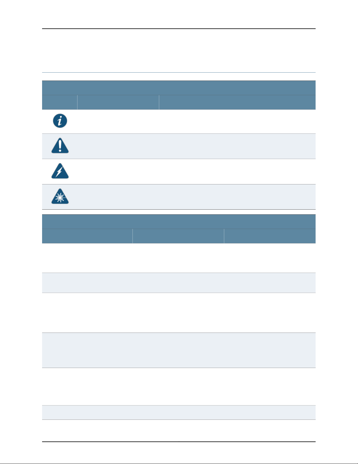
Notice Icons
DescriptionMeaningIcon
Indicates important features or instructions.Informational note
Caution
Text and Syntax Conventions
Fixed-width text like this
Italic text like this
Indicates a situation that might result in loss of data or hardware
damage.
Alerts you to the risk of personal injury or death.Warning
Alerts you to the risk of personal injury from a laser.Laser warning
Represents text that you type.Bold text like this
Represents output that appears on the
terminal screen.
•
Introduces important new terms.
•
Identifies book names.
•
Identifies RFC and Internet drafttitles.
ExamplesDescriptionConvention
To enter configuration mode, type the
configure command:
user@host> configure
user@host> show chassis alarms
No alarms currently active
•
A policy term is a named structurethat
defines match conditions and actions.
•
Junos System Basics Configuration
Guide
•
RFC 1997, BGP Communities Attribute
Italic text like this
Plain text like this
Represents variables (options for which
you substitute a value) in commands or
configuration statements.
Represents names of configuration
statements, commands, files, and
directories; IP addresses; configuration
hierarchy levels; or labels on routing
platform components.
Configure the machine’s domain name:
[edit]
root@# set system domain-name
domain-name
•
To configure a stub area, include the
stub statement at the [edit protocols
ospf area area-id] hierarchy level.
•
The console port is labeled CONSOLE.
stub <default-metric metric>;Enclose optional keywords or variables.< > (angle brackets)
Copyright © 2010, Juniper Networks, Inc.xxiv
Page 25

Text and Syntax Conventions
About This Topic Collection
ExamplesDescriptionConvention
| (pipe symbol)
# (pound sign)
[ ] (square brackets)
Indention and braces ( { } )
; (semicolon)
J-Web GUI Conventions
Bold text like this
Indicatesa choice between the mutually
exclusivekeywordsor variableson either
side of the symbol. The set of choices is
often enclosed in parentheses for clarity.
same line as the configurationstatement
to which it applies.
Enclose a variable for which you can
substitute one or more values.
Identify a level in the configuration
hierarchy.
Identifies a leaf statement at a
configuration hierarchy level.
Represents J-Web graphical user
interface (GUI) items you click or select.
broadcast | multicast
(string1 | string2 | string3)
rsvp { # Required for dynamic MPLS onlyIndicates a comment specified on the
community name members [
community-ids ]
[edit]
routing-options {
static {
route default {
nexthop address;
retain;
}
}
}
•
In the Logical Interfaces box, selectAll
Interfaces.
•
To cancel the configuration, click
Cancel.
> (bold right angle bracket)
Documentation Feedback
We encourage you to provide feedback, comments, and suggestions so that we can
improve the documentation. Send e-mail to techpubs-comments@juniper.net with the
following:
•
Document URL or title
•
Page number if applicable
•
Software version
•
Your name and company
Separates levels in a hierarchy of J-Web
selections.
In the configuration editor hierarchy,
select Protocols>Ospf.
xxvCopyright © 2010, Juniper Networks, Inc.
Page 26

Complete Hardware Guide for EX8208 Ethernet Switches
Requesting Technical Support
Technicalproduct support is availablethrough the Juniper Networks Technical Assistance
Center (JTAC). If you are a customer with an active J-Care or JNASC support contract,
or are covered under warranty, and need post-sales technical support, you can access
our tools and resources online or open a case with JTAC.
•
JTAC policies—For a complete understanding of our JTAC procedures and policies,
review the JTAC User Guide located at
http://www.juniper.net/us/en/local/pdf/resource-guides/7100059-en.pdf .
•
Product warranties—For product warranty information, visit
http://www.juniper.net/support/warranty/ .
•
JTAC hours of operation—The JTAC centers have resources available 24 hours a day,
7 days a week, 365 days a year.
Self-Help Online Tools and Resources
For quick and easy problem resolution, Juniper Networks has designed an online
self-service portal called the Customer Support Center (CSC) that provides you with the
following features:
•
Find CSC offerings: http://www.juniper.net/customers/support/
•
Search for known bugs: http://www2.juniper.net/kb/
•
Find product documentation: http://www.juniper.net/techpubs/
•
Find solutions and answer questions using our Knowledge Base: http://kb.juniper.net/
•
Download the latest versions of software and review release notes:
http://www.juniper.net/customers/csc/software/
•
Search technical bulletins for relevant hardware and software notifications:
https://www.juniper.net/alerts/
•
Join and participate in the Juniper Networks Community Forum:
http://www.juniper.net/company/communities/
•
Open a case online in the CSC Case Management tool: http://www.juniper.net/cm/
To verify service entitlement by product serial number,use our Serial Number Entitlement
(SNE) Tool: https://tools.juniper.net/SerialNumberEntitlementSearch/
Opening a Case with JTAC
You can open a case with JTAC on the Web or by telephone.
•
Use the Case Management tool in the CSC at http://www.juniper.net/cm/ .
•
Call 1-888-314-JTAC (1-888-314-5822 toll-free in the USA, Canada, and Mexico).
For international or direct-dial options in countries without toll-free numbers, see
http://www.juniper.net/support/requesting-support.html .
Copyright © 2010, Juniper Networks, Inc.xxvi
Page 27

PART 1
Switch and Components Overview and
Specifications
•
EX8208 Switch Overview on page 3
•
Component Descriptions on page 17
•
Component Specifications on page 57
1Copyright © 2010, Juniper Networks, Inc.
Page 28

Complete Hardware Guide for EX8208 Ethernet Switches
Copyright © 2010, Juniper Networks, Inc.2
Page 29

CHAPTER 1
EX8208 Switch Overview
•
EX8208 Switch Hardware Overview on page 3
•
EX8208 Switch Configurations on page 6
•
Chassis Physical Specifications of an EX8208 Switch on page 9
•
Understanding EX8208 Switch Component and Functionality Redundancy on page 11
•
Slot Numbering for an EX8208 Switch on page 13
EX8208 Switch Hardware Overview
Juniper Networks EX8208 Ethernet Switches provide high performance, scalable
connectivity, and carrier-class reliability for high-density environments such as
campus-aggregation and data-center networks. The EX8208 switch is a modular system
that provides high availability and redundancy for all major hardware components,
including Routing Engines, switch fabric, fan tray, and power supplies.
You can manage EX8208 switches using the same interfaces that you use for managing
other devices running the Juniper Networks Junos operating system (Junos OS)—the
command-line interface (CLI), the J-Web graphical interface, and the Network and
Security Manager (NSM).
Software
•
Software on page 3
•
Chassis Physical Specifications on page 4
•
Routing Engines and Switch Fabric on page 5
•
Line Cards on page 5
•
Cooling System on page 5
•
Power Supplies on page 6
The Juniper Networks EX Series Ethernet Switches run under the Juniper Networks Junos
OS, which provides Layer 2 and Layer 3 switching, routing, and security services. The
same Junos OS code base that runs on EX Series switches also runs on all Juniper
Networks J Series, M Series, MX Series, and T Series routers.
3Copyright © 2010, Juniper Networks, Inc.
Page 30
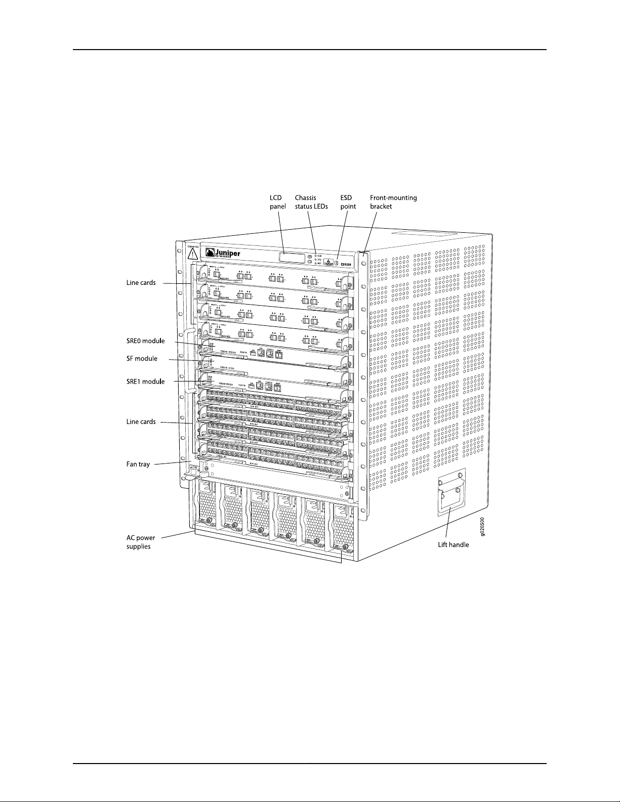
Complete Hardware Guide for EX8208 Ethernet Switches
Chassis Physical Specifications
The EX8208 switch is 14 rack units (14 U) in size (1/3 rack); three EX8208 switches can
fit in a standard 42 U rack. Each EX8208 switch is designed to optimize rack space and
cabling. See Figure 1 on page 4.
Figure 1: EX8208 Switch
The EX8208 switch has a chassis-level LCD panel that displays Routing Engine and
switch fabric status as well as chassis components’ alarm information for rapid problem
identification. The LCD panel provides a user-friendly interface for performing initial
switch configuration, rolling back a configuration, or restoring the switch to its default
settings. See “LCD Panel in an EX8200 Switch” on page 17.
The EX8208 chassis backplane distributes the data, control, and management signals
to various system components along with distributing power throughout the system.
See “Chassis Physical Specifications of an EX8208 Switch” on page 9.
Copyright © 2010, Juniper Networks, Inc.4
Page 31

Routing Engines and Switch Fabric
Switchingfunctionality,systemmanagement, and system controlfunctions of an EX8208
switch are performed by a Switch Fabric and Routing Engine (SRE) module. See “Switch
Fabric and Routing Engine (SRE) Module in an EX8208 Switch” on page 24. An SRE
module contains a Routing Engine and switch fabric. The SRE modules are installed in
the front of the chassis in the slots labeled SRE0 and SRE1. See “Slot Numbering for an
EX8208 Switch” on page 13. A base configuration EX8208 switch has one SRE module.
A redundant configuration EX8208 switch has a second SRE module. See “EX8208
Switch Configurations” on page 6.
The Switch Fabric (SF) module, working with the SRE module, provides the necessary
switchingfunctionality to a baseconfiguration EX8208 switch. The SF module is installed
in the front of the chassis in the slot labeled SF. In a redundant configuration the SF
module provides a redundant switch fabric. The additional switch fabric provides full 2+1
switch fabric redundancy to the switch. See “Switch Fabric (SF) Module in an EX8208
Switch” on page 28.
Line Cards
Chapter 1: EX8208 Switch Overview
Cooling System
The EX8208 switch features eight horizontal line card slots and supports the line rate
for each line card. The line cards in EX8200 switches combine a Packet Forwarding
Engine and Ethernet interfaces on a single assembly. Line cards are field-replaceable
units (FRUs) that can be installed in the line card slots labeled 0 through 7 on the front
of the switch chassis. See “Slot Numbering for an EX8208 Switch” on page 13. All line
cards are hot-removable and hot-insertable.
The following line cards are available for EX8208 switches:
•
8-port 10-Gigabit Ethernet SFP+ line card: This line card has eight 10-gigabit SFP+
ports on its faceplate in which you can install SFP+ transceivers. See “8-port SFP+
Line Card in an EX8200 Switch” on page 30.
•
40-port 10-Gigabit Ethernet SFP+ line card: Thisline card has 40 10-gigabit SFP+ ports
on its faceplate in which you can install either SFP+ or SFP transceivers. See “40-port
SFP+ Line Card in an EX8200 Switch” on page 31.
•
48-port 100/1000 SFP line card: This line card has 48 1-gigabit SFP ports on its
faceplate in which you can install SFP transceivers. See “48-port SFP Line Card in an
EX8200 Switch” on page 33.
•
48-port 10/100/1000 RJ-45 line card: This line card had 48 10/100/1000 Gigabit
Ethernet ports with RJ-45 connectors on its faceplate. See “48-port RJ-45 Line Card
in an EX8200 Switch” on page 34.
The cooling system in an EX8208 switch consists of a hot-removable and hot-insertable
fan tray. The fan tray contains 12 fans. The fan tray installs vertically on the left front of
the chassis and provides side-to-side chassis cooling. See “Cooling System and Airflow
in an EX8208 Switch” on page 53.
5Copyright © 2010, Juniper Networks, Inc.
Page 32

Complete Hardware Guide for EX8208 Ethernet Switches
Power Supplies
Power supplies for the EX8208 switch are fully redundant, load-sharing, and
hot-removable and hot-insertable field-replaceable units (FRUs). Each EX8208 switch
chassis can hold up to six 2000 W AC, six 3000 W AC, or six 2000 W DC power supplies.
The 2000 W AC power supplies support both low-voltage line (100–120 VAC) and
high-voltage line (200–240 VAC) AC power configurations on an EX8208 switch. Each
2000 W AC power supply delivers 2000 W of powerat high-voltageline (200–240 VAC)
or 1200 W at low-voltage line (100–120 VAC) to the EX8208 chassis.
Each 3000 W AC power supply delivers 3000 W of power at high-voltageline (200–240
VAC) input to the EX8208 chassis. Low-voltage line input is not supported for the 3000
W AC power supplies on the EX8208 switch.
Each DC power supply delivers 2000 W of power to the chassis when the input voltage
is in the range –40 VDC through –72 VDC.
Only two AC power supplies are required for the base AC configuration and switch
powerup. The redundant AC configuration ships with six AC power supplies to provide
the capacity to power the system using N+1 or N+N power redundancy. See “AC Power
Supplyin an EX8200 Switch”on page40 and “EX8208 SwitchConfigurations”on page 6.
The redundant DC configuration ships with four DC power supplies. The dual inputs of
the DC supplies provide direct support for N+N power redundancy. The redundant
configurationalso provides sufficient capacity for N+1 redundancy in most configurations;
if necessary,up to twoadditional DC supplies can be added to the system. See “DC Power
Supplyin an EX8200 Switch”on page48 and “EX8208 Switch Configurations”on page 6.
CAUTION: Mixing different types of power supplies in the same chassis is not supported.
Related Topics Field-Replaceable Units in an EX8208 Switch on page 23•
• Connecting and Configuring an EX Series Switch (CLI Procedure) on page 190
• Connecting and Configuring an EX Series Switch (J-Web Procedure) on page 192
EX8208 Switch Configurations
Table 1 on page 7 lists the seven sample hardware configurations for an EX8208
switch—base (AC), redundant (AC and DC versions), and fully loaded chassis (AC and
DC versions)—and the components included in each configuration.
The switch is shipped in only four of these seven configurations: base (AC with 2000 W
AC power supplies), base (AC with 3000 W AC power supplies), redundant (AC with
2000 W AC power supplies), and redundant (DC).
Copyright © 2010, Juniper Networks, Inc.6
Page 33

Table 1: EX8208 Switch Hardware Configurations
Base configuration (AC with 2000 W AC power supplies)
Base configuration (AC with 3000 W AC power supplies)
Chapter 1: EX8208 Switch Overview
Configuration ComponentsSwitch Configuration
•
Chassis with backplane
•
One fan tray
•
One Switch Fabric and Routing Engine (SRE) module
•
One Switch Fabric (SF) module
•
Two 2000 W AC power supplies
•
Two power cords
•
Eight line card cover panels
•
Four power supply cover panels
•
Chassis with backplane
•
One fan tray
•
One Switch Fabric and Routing Engine (SRE) module
•
One Switch Fabric (SF) module
•
Two 3000 W AC power supplies
•
Two power cords
•
Eight line card cover panels
•
Four power supply cover panels
Redundantconfiguration(ACwith 2000 W ACpower supplies)
Redundant configuration (DC)
Fully loaded chassis configuration (AC with 2000 W AC power
supplies)
•
Chassis with backplane
•
One fan tray
•
Two SRE modules
•
One SF module
•
Six 2000 W AC power supplies
•
Six power cords
•
Eight line card cover panels
•
Chassis with backplane
•
One fan tray
•
Two SRE modules
•
One SF module
•
Four 2000 W DC power supplies
•
16 DC power cable lugs
•
Eight line card cover panels
•
Chassis with backplane
•
One fan tray
•
Two SRE modules
•
One SF module
•
Six 2000 W AC power supplies
•
Six power cords
•
Eight line cards
7Copyright © 2010, Juniper Networks, Inc.
Page 34

Complete Hardware Guide for EX8208 Ethernet Switches
Table 1: EX8208 Switch Hardware Configurations (continued)
Configuration ComponentsSwitch Configuration
•
Fully loaded chassis configuration (AC with 3000 W AC power
supplies)
Fully loaded chassis configuration (DC)
Chassis with backplane
•
One fan tray
•
Two SRE modules
•
One SF module
•
Six 3000 W AC power supplies
•
Six power cords
•
Eight line cards
•
Chassis with backplane
•
One fan tray
•
Two SRE modules
•
One SF module
•
Six 2000 W DC power supplies
•
24 DC power cable lugs
•
Eight line cards
Related Topics Chassis Physical Specifications of an EX8208 Switch on page 9•
NOTE: You can install up to eight line cards (any combination of line cards) in the
switch.
NOTE: Line cards are not part of the base or redundant configuration. You must order
them separately.
NOTE: If you want to purchase additional power supplies (AC or DC) for your switch
configuration, you must order them separately.
• Switch Fabric and Routing Engine (SRE) Module in an EX8208 Switch on page 24
• Switch Fabric (SF) Module in an EX8208 Switch on page 28
• 8-port SFP+ Line Card in an EX8200 Switch on page 30
• 40-port SFP+ Line Card in an EX8200 Switch on page 31
• 48-port SFP Line Card in an EX8200 Switch on page 33
• 48-port RJ-45 Line Card in an EX8200 Switch on page 34
• AC Power Supply in an EX8200 Switch on page 40
• Cooling System and Airflow in an EX8208 Switch on page 53
• Backplane in an EX8208 Switch on page 55
Copyright © 2010, Juniper Networks, Inc.8
Page 35

Chassis Physical Specifications of an EX8208 Switch
The EX8208 switch chassis is a rigid sheet-metal structure that houses the other switch
components. Table 2 on page 9 summarizes the physical specifications of the EX8208
switch chassis. See Figure 2 on page 10.
Table 2: Physical Specifications of the EX8208 Switch Chassis
ValueDescription
24.25 in. (61.6 cm)Chassis height
•
Chassis width
Chassis depth
Weight
17.25 in. (43.82 cm)
•
The outer edges of the front-mounting brackets extend the width to 19 in. (48.3 cm).
•
20 in. (50.8 cm)
•
The depth from the front-mounting bracket to chassis rear is 20.69 in. (52.6 cm).
•
Chassis with backplane: 89 lb (41 kg)
•
Base configuration: 149 lb (68 kg)
•
Redundant configuration: 187 lb (85 kg)
•
Fully loaded chassis: 284 lb (129 kg)
See “EX8208 Switch Configurations” on page 6.
Chapter 1: EX8208 Switch Overview
NOTE: The fully loaded chassis weight includes the heaviest line cards in all eight
slots. If your switch configuration has lighter line cards, the fully loaded chassis weight
will be in the 268–284 lb (122–129 kg) range.
9Copyright © 2010, Juniper Networks, Inc.
Page 36

Complete Hardware Guide for EX8208 Ethernet Switches
Figure 2: EX8208 Switch
Related Topics Rack Requirements for an EX8208 Switch on page 97•
You can mount an EX8200 switch on a standard 19-in. four-post rack or a standard
800-mm enclosed cabinet. Up to three EX8208 switches can be installed in a standard
(42 rack unit (U)) rack provided the rack can handle their combined weight.
Lift handlesare provided on either side of the switch to facilitatethe handling of a chassis
with only the backplane installed.
WARNING: Do not use the lift handles to lift the chassis unless the chassis is empty
(that is, contains only the backplane). Failure to heed this warning can result in injury.
See “Mounting an EX8208 Switch on a Rack or Cabinet Using a Mechanical Lift” on
page 141 or “Mounting an EX8208 Switch on a Rack or Cabinet Without Using a
Mechanical Lift” on page 143 for instructions for moving a loaded chassis.
• Cabinet Requirements and Specifications for an EX8208 Switch on page 100
• Mounting an EX8208 Switch on a Rack or Cabinet on page 138
Copyright © 2010, Juniper Networks, Inc.10
Page 37

Chapter 1: EX8208 Switch Overview
• Installing and Removing EX8208 Switch Hardware Components on page 149
Understanding EX8208 Switch Component and Functionality Redundancy
The Juniper Networks EX8208 Ethernet Switch is available as a fully redundant system.
A redundant EX8208 switch configuration is designed so that no single point of failure
can cause the entire switch to fail. See “EX8208 Switch Configurations” on page 6.
This topic describes:
•
Hardware Components That Provide Redundancy on page 11
•
Routing Engine and Control Redundancy on page 12
•
Switch Fabric Redundancy on page 12
Hardware Components That Provide Redundancy
The following hardware components provide redundancy to an EX8208 switch:
•
SRE modules—An EX8208 switch can have either one Switch Fabric and Routing
Engine (SRE) module or two SRE modules. If two SRE modules are installed, one SRE
module functions as the master and the other functions as the backup. If the master
SRE module fails or is removed the backup module takes over as the master SRE
module.
When the SRE modules are configuredfor gracefulswitchover, the backup SRE module
automatically synchronizes its configuration and state with those of the master SRE
module.Any update to the masterSRE module is replicated on the backup SRE module.
If the backup module assumes mastership, packet forwarding continues through the
switch.
•
Power supplies—You can install up to six AC or six DC power supplies in an EX8208
switch. Each power supply connects to the backplane of the chassis, which distributes
the output power produced by the power supplies to different switch components.
(See “Backplane in an EX8208 Switch”on page55.) Each powersupply providespower
to all the components in the switch.
An N+1 power configurationis requiredfor Juniper Networks EX8200 Ethernet Switches.
In an N+1 power configuration, if one power supply fails or is removed, the remaining
power supplies continue to supply power for the entire system without interruption. If
dual power feed redundancy is required, the required power configuration is N+N. The
DC power supplies provide independent A and B power feeds so that dual power
redundancy is available even in an N+1 power configuration. See “AC Power Supply in
an EX8200 Switch” on page 40 and “DC PowerSupplyin an EX8200 Switch”on page 48.
•
Cooling system—The cooling system in an EX8200 switch consists of a single fan tray.
The fan tray contains 12 fans. Under normal operating conditions, the fans in the fan
tray run at less than full speed.
The fans are controlled by two fan tray controllers. The fans are numbered 1 through
12. Fans 1 through 6 are controlled by the first fan tray controller. Fans 7 through 12 are
controlled by the second fan tray controller. If one fan tray controller fails, the other
11Copyright © 2010, Juniper Networks, Inc.
Page 38

Complete Hardware Guide for EX8208 Ethernet Switches
fan tray controller keeps half the fans working. This allows the switch to continue to
operate normally as long as the remaining fans cool the chassis sufficiently.
The fan tray continues to operateindefinitely and provides sufficient cooling even when
a single fan fails provided the room temperature is within the operating range. See
“Cooling System and Airflow in an EX8208 Switch” on page 53.
Routing Engine and Control Redundancy
Each SRE module contains switch fabric circuitry, Routing Engine circuitry, and switch
control and management circuitry. An EX8208 switch can have one SRE module or two
SRE modules. If a switch has two SRE modules, one functions as the master while the
other functions as a backup and is in standby mode. This provides the switch with full
redundancy (1+1) for Routing Engine and switch control functionality.
Table 3 on page 12 shows the available slots in the EX8208 chassis and the Routing
Engine and control redundancy associated with different SRE module and Switch Fabric
(SF) module combinations.
Table 3: Routing Engine and Control Redundancy for EX8208 Switches
configuration
configuration
Switch Fabric Redundancy
The switch fabric circuitry in an EX8208 switch is distributed across three modules—two
SRE modules and one SF module. Any two of these three modules must be installedand
functional to provide a working switch fabric with no redundancy.The third module, when
present, provides partial redundancy (2+1) for the switching functionality, such that if
any one of the two functional modules becomes nonoperational, the third module takes
over.
Table 4 on page 12 shows the available slots in an EX8208 chassis and the switch fabric
redundancy associated with different SRE module and SF module combinations.
Routing Engine and
Control RedundancySlot SFSlot SRE1Slot SRE0SwitchConfiguration
NoSF moduleEmptySRE moduleBase configuration
NoSF moduleSRE moduleEmptyBase configuration
YesEmptySRE moduleSRE moduleUser-defined
YesSF moduleSRE moduleSRE moduleRedundant
Table 4: Switch Fabric Redundancy for EX8208 Switches
Switch Fabric
RedundancySlot SFSlot SRE1Slot SRE0SwitchConfiguration
NoSF moduleEmptySRE moduleBase configuration
Copyright © 2010, Juniper Networks, Inc.12
Page 39

Table 4: Switch Fabric Redundancy for EX8208 Switches (continued)
configuration
configuration
Related Topics Switch Fabric and Routing Engine (SRE) Module in an EX8208 Switch on page 24•
• Switch Fabric (SF) Module in an EX8208 Switch on page 28
Slot Numbering for an EX8208 Switch
Chapter 1: EX8208 Switch Overview
Switch Fabric
RedundancySlot SFSlot SRE1Slot SRE0SwitchConfiguration
NoSF moduleSRE moduleEmptyBase configuration
NoEmptySRE moduleSRE moduleUser-defined
YesSF moduleSRE moduleSRE moduleRedundant
An EX8208 chassis accepts eight line cards, two Switch Fabric and Routing Engine (SRE)
modules, one Switch Fabric (SF) module, one fan tray, and six power supplies (AC or
DC). All 11 slots for the line cards and the modules run horizontallyacross the front of the
chassis. The fan tray slot runs vertically on the left of the chassis front. The six power
supply slots run vertically across the front bottom of the chassis.
This topic describes:
•
Slot Numbering for SRE and SF Module Slots and Line Card Slots on page 13
•
Slot Numbering for the Power Supply Slots on page 15
Slot Numbering for SRE and SF Module Slots and Line Card Slots
Table 5 on page 13 lists the slot numbers on the EX8208 chassis and the components
those slots accept.
Table 5: Slot Numbering for an EX8208 Switch
Components Accepted in SlotSlot Label
Line card0
Line card1
Line card2
Line card3
SRE moduleSRE0
SF moduleSF
SRE moduleSRE1
13Copyright © 2010, Juniper Networks, Inc.
Page 40

Complete Hardware Guide for EX8208 Ethernet Switches
Table 5: Slot Numbering for an EX8208 Switch (continued)
Components Accepted in SlotSlot Label
Line card4
Line card5
Line card6
Line card7
Figure 3 on page 14 shows the slot numbering, which is on the front left of the chassis.
Figure 3: Slot Numbering for an EX8208 Switch
Slots 0 through 7 accept one of the line cards available. See “Installing a Line Card in an
EX8200 Switch” on page 160.
Slots SRE0 and SRE1 accept only the SRE module. You can install one SRE module or
two SRE modules based on the configuration of your switch. See “Switch Fabric and
Routing Engine (SRE) Module in an EX8208 Switch” on page 24.
Copyright © 2010, Juniper Networks, Inc.14
Page 41

NOTE: We recommend that you install two SRE modules for redundancy. If you install
only one SRE module,we recommend that you install it in the slot SRE0. See “Installing
an SRE Module in an EX8208 Switch” on page 155.
Slot SF accepts only the SF module. See “Switch Fabric (SF) Module in an EX8208
Switch”on page28. An EX8208 switch can have either zeroSF modules or one SF module
based on your switch configuration. The SF module is keyed so that it does not fit in any
other slot in the chassis. See “Installing an SF Module in an EX8208 Switch” on page 157.
Slot Numbering for the Power Supply Slots
The chassis has six vertical slots on its front bottom. You can install up to six power
supplies (either all AC or all DC) in these slots, which are labeled PSU 0 through PSU 5
(from left to right). Table 6 on page 15 lists the slot numbers for the power supplies on
an EX8208 switch. See “AC Power Supply in an EX8200 Switch” on page 40 and “DC
Power Supply in an EX8200 Switch” on page 48.
Chapter 1: EX8208 Switch Overview
CAUTION: Mixing different types of powersupplies in the same chassis is not a supported
configuration.
Table 6: Slot Numbering for Power Supply Slots on an EX8208 Switch Chassis Front
Components Accepted in SlotSlot Label
Power supplyPSU 0
Power supplyPSU 1
Power supplyPSU 2
Power supplyPSU 3
Power supplyPSU 4
Power supplyPSU 5
Figure 4 on page 16 shows the slot numbering for the power supply slots in an EX8208
switch.
15Copyright © 2010, Juniper Networks, Inc.
Page 42

Complete Hardware Guide for EX8208 Ethernet Switches
Figure 4: Slot Numbering for Power Supply Slots on an EX8208 Switch
Chassis Front
NOTE: Power supplies can be installed in any slot. You do not have to install them in
serial order. See “Installing an AC Power Supply in an EX8200 Switch” on page 150 and
“Installing a DC Power Supply in an EX8200 Switch” on page 152.
Related Topics • 8-port SFP+ Line Card in an EX8200 Switch on page 30
• 40-port SFP+ Line Card in an EX8200 Switch on page 31
• 48-port SFP Line Card in an EX8200 Switch on page 33
• 48-port RJ-45 Line Card in an EX8200 Switch on page 34
• EX8208 Switch Hardware Overview on page 3
Copyright © 2010, Juniper Networks, Inc.16
Page 43

CHAPTER 2
Component Descriptions
•
LCD Panel in an EX8200 Switch on page 17
•
Chassis Status LEDs in an EX8200 Switch on page 22
•
Field-Replaceable Units in an EX8208 Switch on page 23
•
Switch Fabric and Routing Engine (SRE) Module in an EX8208 Switch on page 24
•
SRE Module LEDs in an EX8208 Switch on page 26
•
Management Port LEDs in EX8200 Switches on page 27
•
Switch Fabric (SF) Module in an EX8208 Switch on page 28
•
SF Module LEDs in an EX8208 Switch on page 29
•
8-port SFP+ Line Card in an EX8200 Switch on page 30
•
40-port SFP+ Line Card in an EX8200 Switch on page 31
•
48-port SFP Line Card in an EX8200 Switch on page 33
•
48-port RJ-45 Line Card in an EX8200 Switch on page 34
•
Line Card LEDs in an EX8200 Switch on page 35
•
Network Port LEDs in an EX8200 Switch on page 37
•
AC Power Supply in an EX8200 Switch on page 40
•
AC Power Supply LEDs in an EX8200 Switch on page 46
•
DC Power Supply in an EX8200 Switch on page 48
•
DC Power Supply LEDs in an EX8200 Switch on page 50
•
Cooling System and Airflow in an EX8208 Switch on page 53
•
Backplane in an EX8208 Switch on page 55
LCD Panel in an EX8200 Switch
The LCD panel on the top front of the EX8200 switch chassis shows two lines of text
with a maximum of 16 characters in each line. The LCD panel displays a variety of
information about the switch and provides menu options to perform basic operations
such as initial configuration and switch reboot.
There are two navigation buttons—Menu and Enter—to the right of the LCD panel.
See Figure 5 on page 18.
17Copyright © 2010, Juniper Networks, Inc.
Page 44

Complete Hardware Guide for EX8208 Ethernet Switches
Figure 5: LCD Panel in an EX8200 Switch
You can configure the second line of the LCD panel to display a custom message. If the
LCD panel is configured to display a custom message, the Menu button and the Enter
buttonare disabled.See Configuringthe LCD Panel on EX Series Switches (CLI Procedure).
The LCD panel has a backlight. If the LCD panel is idle for 60 seconds, the backlight turns
off. You can turn on the backlight by pressing the Menu or Enter button once. Afterturning
on the backlight, you can toggle between the LCD menus by pressing the Menu button
and navigate through the menu options by pressing the Enter button.
NOTE: The chassis viewer in the J-Web interfacealso displays the LCD panel. From the
J-Web interface, you can view real-time status information in the LCD panel. See
Dashboard for EX Series Switches.
LCD Panel Modes
This topic describes:
•
LCD Panel Modes on page 18
•
LCD Panel Menus on page 19
The LCD operates in four modes: boot, idle, status, and maintenance.
The LCD operates in boot mode during switch reboot.
The boot mode displays the key milestones in the switch boot process. The boot mode
does not have any menu options. After the boot process is complete, the LCD
automatically reverts to the Idle menu.
In the idle mode, line two of the Idle menu displaysthe network ports’ StatusLED modes
and the total number of alarms in the system. The number of alarms is updated every
second.
The status mode allows you to get status information for the following items:
•
Switch fabric in Switch Fabric and Routing Engine (SRE) modules in EX8208 switches
•
Routing Engine (RE) and switch fabric in Switch Fabric (SF) module(s) in EX8216
switches
•
Power supplies
•
Fan tray(s) and chassis temperature
•
Junos OS version installed
Copyright © 2010, Juniper Networks, Inc.18
Page 45

LCD Panel Menus
Chapter 2: Component Descriptions
The maintenance mode allows you to cycle through options for configuring and
troubleshooting the switch:
•
System halt
•
Reboot system
•
Load rescue configuration
•
Revert to factory configuration
•
EZSetup
The LCD has three menus: Idle, Status, and Maintenance. In each of these menus, line
one of the LCD panel displays the hostname of the switch. Toggle between the LCD
menus by pressing the Menu button. Navigate through the menu options by pressing the
Enter button.
Table 7 on page 19 describes the LCD menu options.
Table 7: LCD Panel Menu Options for the EX8200 Switch
DescriptionMenu
Idle
In the Idle menu:
•
Press Enter to cycle through the Status LED modes, which are port status indicators:
•
ADM (enabled/disabled)
•
SPD (speed)
•
DPX (duplex)
See “Network Port LEDs in an EX8200 Switch” on page 37 for information on the Status LED.
•
Press Menu to exit the Idle menu and go to the Status menu.
19Copyright © 2010, Juniper Networks, Inc.
Page 46

Complete Hardware Guide for EX8208 Ethernet Switches
Table 7: LCD Panel Menu Options for the EX8200 Switch (continued)
DescriptionMenu
Status
The Status menu has the following options:
•
Switch fabric status—Choose one of the following:
•
Press Enter to display the status of the switch fabric in the SRE modules (SRE0 and SRE1) in EX8208
switches and the SF modules (SF) in EX8216 switches: OK, Fld (failed), ABS (absent)
•
Press Menu to go to the next option in the Status menu.
•
Power supply status (1)—Choose one of the following:
•
Press Enter to display the status of power supplies 0 and 1: OK, Fld, ABS.
•
Press Menu to go to the next option in the Status menu.
•
Power supply status (2)—Choose one of the following:
•
Press Enter to display the status of power supplies 2, 3, 4, and 5: OK, Fld, ABS.
•
Press Menu to go to the next option in the Status menu.
•
Environment status—Choose one of the following:
•
Press Enter to display the status of the fan tray(s) and the chassis temperature:
•
Fan tray(s) status: OK, Fld, ABS
•
Chassis temperature status: OK, High, Shutdown
•
Press Menu to go to the next option in the Status menu.
•
Junos version status—Choose one of the following:
•
Press Enter to display the version of Junos OS for EX Series switches loaded on the switch.
•
Press Menu to go to the next option in the Status menu.
•
EXIT STAT MENU?—Choose one of the following:
•
Press Enter to exit the Status menu.
•
Press Menu to return to the Switch fabric status option.
If you do not want users to use Status menu options, disable the entire menu or individual menu options. See
Configuring the LCD Panel on EX Series Switches (CLI Procedure).
Copyright © 2010, Juniper Networks, Inc.20
Page 47

Table 7: LCD Panel Menu Options for the EX8200 Switch (continued)
DescriptionMenu
Chapter 2: Component Descriptions
Maintenance
The Maintenance menu has the following options:
•
SYSTEM HALT?—Choose one of the following:
•
Press Enter to halt the master SRE module in an EX8208 switch or to halt the master RE module in an
EX8216 switch. Press Enter again to confirm the halt.
In a base configuration switch, the master SRE or RE module will be gracefully halted but not powered
off. Press Enter on your management device or power cycle the switch to bring the switch back up.
In a redundant configuration, the backup SRE or RE module takes over mastership when the master SRE
or RE module is halted. To completely halt the switch, use the request system halt other-routing-engine
CLI command to halt the backup SRE or RE module before halting the master SRE or RE module. Press
Enter on your management device or power cycle the switch to bring the switch back up.
See “EX8208 Switch Configurations” on page 6 or EX8216 Switch Configurations for information on
configuration types.
•
Press Menu to go to the next option in the Maintenance menu.
•
SYSTEM REBOOT?—Choose one of the following:
•
Press Enter to reboot the master SRE or RE module. Press Enter again to confirm the reboot.
•
Press Menu to go to the next option in the Maintenance menu.
•
LOAD RESCUE?—Choose one of the following:
•
Press Enter to roll back the switch to the previous valid configuration. Press Enter again to confirm the
rollback.
•
Press Menu to go to the next option in the Maintenance menu.
•
FACTORY DEFAULT?—Choose one of the following:
•
Press Enter to restore the switch to the factory default configuration. Press Enter again to confirm the
restoration. The LCD flashes a success or failure message and returns to the Idle menu.
•
Press Menu to go to the next option in the Maintenance menu.
•
ENTER EZSETUP?—Choose one of the following:
•
Press Enter to launch EZSetup. Press Enter again to confirm the launch.
EZSetup configures DHCP and enables the J-Web user interface on the switch. The LCD flashes a success
or failure message for approximately 10 seconds and returns to the Idle menu.
•
Press Menu to go to the next option in the Maintenance menu.
NOTE: You can use the EZSetup option only if the switch is in the factory default configuration.
•
EXIT MAINT MENU?—Choose one of the following:
•
Press Enter to exit the Maintenance menu.
•
Press Menu to return to the SYSTEM HALT option.
If you do not want users to use Maintenance menu options, disable the entire menu or individual menu options.
See Configuring the LCD Panel on EX Series Switches (CLI Procedure).
Related Topics Chassis Status LEDs in an EX8200 Switch on page 22•
You can view the information about the LCD panel in EX8200 switches by executing the
command show chassis hardware. It shows the version, part number, serial number, and
description of the LCD panel.
• Field-Replaceable Units in an EX8208 Switch on page 23
• Field-Replaceable Units in an EX8216 Switch
21Copyright © 2010, Juniper Networks, Inc.
Page 48

Complete Hardware Guide for EX8208 Ethernet Switches
• Connecting and Configuring an EX Series Switch (CLI Procedure) on page 190
• Connecting and Configuring an EX Series Switch (J-Web Procedure) on page 192
Chassis Status LEDs in an EX8200 Switch
The top front of the chassis of an EX8200 switch has three LEDs on the right side of the
LCD panel.
See Figure 6 on page 22.
Figure 6: Chassis Status LEDs
Table 8 on page 22 describes the chassis status LEDs in an EX8200 switch, their colors
and states, and the status they indicate. You can view the colors of the three LEDs
remotely through the CLI by issuing the operational mode command show chassis lcd.
Table 8: Chassis Status LEDs in an EX8200 Switch
State and DescriptionColorLED Label (Description)
No alarm.UnlitALM (Alarm)
Major alarm.Red
Minor alarm.Yellow
Switch is powered off.UnlitSYS (System)
Yellow
One or more component failures are generating one or more
alarms.
Switch is operating normally.Green
Switch is powered off.UnlitMST (Master)
Master Routing Engine is operational.Green
A major alarm (red) indicates a critical error condition that requires immediate action.
A minor alarm (yellow) indicates a noncritical condition that requires monitoring or
maintenance. A minor alarm that is left unchecked might cause interruption in service or
performance degradation.
All three LEDs can be lit simultaneously.
Copyright © 2010, Juniper Networks, Inc.22
Page 49

Related Topics LCD Panel in an EX8200 Switch on page 17•
• Understanding Alarm Types and Severity Levels on EX Series Switches
Field-Replaceable Units in an EX8208 Switch
Field-replaceable units (FRUs) are switch components that you can replace at your site.
The switch uses these types of FRUs:
•
Hot-insertable and hot-removable—You can remove and replace these components
without powering off the switch or disrupting the switching function.
•
Hot-pluggable—You can remove and replace these components without powering off
the switch, but the switching function is interrupted until you replace the component.
Table 9 on page 23 lists the FRUs for the EX8208 switch and their types.
Table 9: FRUs in an EX8208 Switch
TypeFRU
Chapter 2: Component Descriptions
SwitchFabric and Routing Engine (SRE)
module
Switch Fabric (SF) module
8-port SFP+ line card
Hot-insertable and hot-removable.Power supplies
Hot-insertable and hot-removable.Fan tray
Redundant configuration:
•
Master SRE module is hot-pluggable.
•
Backup SRE module is hot-insertable and hot-removable.
Base configuration:
•
Switch must be disabled before the SRE module is removed. See “Taking the SRE
Module Offline in an EX8208 Switch” on page 213.
See “EX8208 Switch Configurations” on page 6.
Redundant configuration:
•
SF module is hot-insertable and hot-removable.
Base configuration:
•
We recommend that you disable the switch before removing the SF module. See
“Taking the SF Module Offline in an EX8208 Switch” on page 216.
See “EX8208 Switch Configurations” on page 6.
Hot-insertable and hot-removable.
40-port SFP+ line card
48-port SFP line card
48-port RJ-45 line card
We recommend that you take the line cards offline before removing them. See
“Removing a Line Card from an EX8200 Switch” on page 218.
Hot-insertable and hot-removable.SFP and SFP+ transceivers
23Copyright © 2010, Juniper Networks, Inc.
Page 50

Complete Hardware Guide for EX8208 Ethernet Switches
NOTE: Line cards are not part of the base or redundant configuration. You must order
them separately.
NOTE: If you have a Juniper J-Care service contract, register any addition, change, or
upgrade of hardware components at
https://www.juniper.net/customers/csc/management/updateinstallbase.jsp. Failure to
do so can result in significant delays if you need replacement parts. This note applies
if you add a new type of line card. It does not apply if you replace these components
with the same type of component.
Related Topics Installing and Removing EX8208 Switch Hardware Components on page 149•
• Removing an SRE Module from an EX8208 Switch on page 215
• Removing an SF Module from an EX8208 Switch on page 217
• Removing a Line Card from an EX8200 Switch on page 218
• Removing an AC Power Supply from an EX8200 Switch on page 207
• Removing a Fan Tray from an EX8208 Switch on page 211
• Removing a Transceiver from an EX Series Switch on page 222
Switch Fabric and Routing Engine (SRE) Module in an EX8208 Switch
The Switch Fabric and Routing Engine (SRE) module performs switching and system
management functions in an EX8208 switch. See Figure 7 on page 25.
You can install one or two SRE modules in an EX8208 switch. A base configuration
EX8208 switch has only one SRE module. See “EX8208 Switch Configurations” on
page 6. You can add a second SRE module to the configuration for Routing Engine and
switch control redundancy. See “Understanding EX8208 Switch Component and
Functionality Redundancy” on page 11.
The SRE modules install horizontally into the front of the chassis in slots labeled SRE0
and SRE1.
Copyright © 2010, Juniper Networks, Inc.24
Page 51

Chapter 2: Component Descriptions
Figure 7: SRE Module in an EX8208 Switch
NOTE: We recommend that you install two SRE modules for redundancy. If you install
only one SRE module, we recommend that you install it in slot SRE0. See “Slot
Numbering for an EX8208 Switch” on page 13.
If two SRE modules are installed, one functions as the master and the other acts as the
backup.If the master SRE module fails or is removed, the backup takes overas the master.
If two SRE modules are installed, the backup SRE module is hot-insertable and
hot-removable, but the master SRE module is hot-pluggable. If only one SRE module is
installed, you must halt the SRE module before removing it.
The SRE module provides these functions:
•
Provides full fabric connectivity to all line cards installed in the chassis
•
Through the switching plane, provides switching functionality to the switch
•
Powers the line cards on and off
•
Controls system resets and boot sequence for the switch
•
Monitors and controls the fan speed, power status for various chassis components,
LCD panel and chassis status LEDs
The SRE module has these components:
•
SRE module LEDs—Indicate system status. See “SRE Module LEDs in an EX8208
Switch” on page 26.
•
Recessed reset button—Power cycles the SRE module when pressed.
Takethe SRE module offline using the CLI before pressing the reset button. See “Taking
the SRE Module Offline in an EX8208 Switch” on page 213.
•
USB port—Provides an interface through which you can install the Junos OS manually.
See “USB Port Specifications for an EX Series Switch” on page 57.
•
Auxiliary port—This port is not enabled on the EX8200 switch. It is reserved for future
use.
25Copyright © 2010, Juniper Networks, Inc.
Page 52

Complete Hardware Guide for EX8208 Ethernet Switches
•
Console port—Connects the SRE module to a system console through a cable with an
RJ-45 connector. See “Connecting an EX Series Switch to a Management Console” on
page 181.
•
Management port—Connects the SRE module through an Ethernet connection to a
management LAN (or any other device that plugs into an Ethernet connection) for
out-of-band management. See “Connecting an EX Series Switch to a Network for
Out-of-Band Management” on page 187.
•
Ejector levers—Used for installing and removing the SRE module.
•
Captive screws—Secure the SRE module in place.
Related Topics Installing an SRE Module in an EX8208 Switch on page 155•
• Removing an SRE Module from an EX8208 Switch on page 215
• Taking the SRE Module Offline in an EX8208 Switch on page 213
SRE Module LEDs in an EX8208 Switch
Each Switch Fabric and Routing Engine (SRE) module has four LEDs on the left side of
the module’s front panel. See Figure 8 on page 26. Table 10 on page 26 describes these
LEDs, their colors and states, and the status they indicate.
Figure 8: SRE Module LEDs in an EX8208 Switch
Table 10: SRE Module LEDs of an EX8208 Switch
State and DescriptionColorLED Label (Description)
SRE module is powered on.GreenON (Power On)
SRE module is powered off.Unlit
GreenST (Status)
•
•
On steadily—SRE module is operating normally.
Blinking—SRE module is booting.
•
On steadily—SRE module has failed.Yellow
SRE module is offline.Unlit
Copyright © 2010, Juniper Networks, Inc.26
Page 53

Table 10: SRE Module LEDs of an EX8208 Switch (continued)
State and DescriptionColorLED Label (Description)
•
GreenMS (Master)
GreenSF (Switch Fabric)
Related Topics Switch Fabric and Routing Engine (SRE) Module in an EX8208 Switch on page 24•
• Installing an SRE Module in an EX8208 Switch on page 155
On steadily—SRE module is the master.
•
Blinking—SRE module is in standby mode.
SRE module is powered off.Unlit
•
On steadily—Switch fabric in the SRE module is operating
normally.
•
Blinking—Switch fabric in the SRE module is in standby mode.
Switch fabric in the SRE module has failed.Yellow
SRE module is powered off.Unlit
Chapter 2: Component Descriptions
• Removing an SRE Module from an EX8208 Switch on page 215
• Taking the SRE Module Offline in an EX8208 Switch on page 213
Management Port LEDs in EX8200 Switches
The management port on EX8200 switches has two LEDs that indicate link/activity and
port status (see Figure 9 on page 27). The management port is set to full-duplex and
the speed is set to 100 Mbps.
Figure 9: LEDs on the Management Port on an EX8200 Switch
Table 11 on page 28 describes the Link/Activity LED.
27Copyright © 2010, Juniper Networks, Inc.
Page 54

Complete Hardware Guide for EX8208 Ethernet Switches
Table 11: Link/Activity LED on the Management Port on EX8200 Switches
State and DescriptionColorLED
•
GreenLink/Activity
Blinking—The port and the link are active, and there is link
activity.
•
On steadily—The port and the link are active, but there is no
link activity.
•
Off—The port is not active.
Table 12 on page 28 describes the Status LED (administrative status).
Table 12: Status LED on the Management Port on EX8200 Switches
State and DescriptionColorLED
•
GreenStatus
On steadily—Administrative status is enabled.
•
Off—Administrative status is disabled.
Related Topics See Switch Fabric and Routing Engine (SRE) Module in an EX8208 Switch on page 24
•
for port location.
• See Routing Engine (RE) Module in an EX8216 Switch for port location.
• Connecting an EX Series Switchto a Network for Out-of-Band Management on page 187
Switch Fabric (SF) Module in an EX8208 Switch
The Switch Fabric (SF) module provides switching functionality.See Figure 10 on page 28.
An EX8208 switch can have either zero SF modules or one SF module. The base
configuration of an EX8208 switch includes one SF module. See “EX8208 Switch
Configurations” on page 6.
Figure 10: SF Module in an EX8208 Switch
The SF module can be installed only in the slot labeled SF. The SF module is keyed so
that it does not fit in the other slots in the chassis. See “Slot Numbering for an EX8208
Switch” on page 13.
Copyright © 2010, Juniper Networks, Inc.28
Page 55

Chapter 2: Component Descriptions
In the base configuration, an SF module is used with a single Switch Fabric and Routing
Engine (SRE) module to build a nonredundant system that provides full bandwidth.
However, a base configuration EX8208 switch has no Routing Engine and switch control
redundancy or switch fabric redundancy. In a base configuration, the main function of
the SF module is to switch data between line cards. See “Understanding EX8208 Switch
Component and Functionality Redundancy” on page 11.
In a redundant configuration, an SF module is used with two SRE modules to achieve
full bandwidth along with Routing Engine and switch control redundancy and switch
fabric redundancy. In a redundant configuration, the main function of the SF module is
to provide a redundant switching plane for the switch. See “Understanding EX8208
Switch Component and Functionality Redundancy” on page 11.
In a redundant configuration, the SF module is hot-pluggable. However, in the base
configuration, you must take the SF module offline before removing it.
The SF module contains logic that determines which SRE module is the master. The
master SRE module controls many internal functions of the SF module.
The SF module provides these functions:
•
Provideredundant data path connectivity for the switch in the redundant configuration
•
Provide nonredundant data path connectivity for the switch in the base configuration
The SF module has these components:
•
SF module LEDs—Indicate system status. See “SF Module LEDs in an EX8208 Switch”
on page 29.
•
Ejector levers—Used for installing and removing the SF module.
•
Captive screws—Secure the SF module in place.
Related Topics Installing an SF Module in an EX8208 Switch on page 157•
• Removing an SF Module from an EX8208 Switch on page 217
• Taking the SF Module Offline in an EX8208 Switch on page 216
SF Module LEDs in an EX8208 Switch
The Switch Fabric (SF) module has two LEDs on the left side of the module’s front panel.
See Figure 11 on page 30.Table 13 on page 30 describes these LEDs, their colors and states,
and the status they indicate.
29Copyright © 2010, Juniper Networks, Inc.
Page 56

Complete Hardware Guide for EX8208 Ethernet Switches
Figure 11: SF Module LEDs in an EX8208 Switch
Table 13: SF Module LEDs of an EX8208 Switch
GreenST (Status)
State and DescriptionColorLED (Description)
•
On steadily—SF module is operating normally.
•
Blinking—Waiting to be configured by the master SwitchFabric
and Routing Engine (SRE) module.
SF module has failed.Yellow
SF module is offline.Unlit
GreenSF (Switch Fabric)
On steadily—Switch fabric in SF module is operating normally.
Blinking—Switch fabric in SF module is offline.
On steadily—Switch fabric in SF module has failed.Yellow
SF module is powered off.Unlit
Related Topics Installing an SF Module in an EX8208 Switch on page 157•
• Removing an SF Module from an EX8208 Switch on page 217
• Taking the SF Module Offline in an EX8208 Switch on page 216
8-port SFP+ Line Card in an EX8200 Switch
The line cards in EX8200 switches combine a Packet Forwarding Engine and Ethernet
interfaces on a single assembly. They are field-replaceable units (FRUs) that can be
installed in the line card slots on the front of the switch chassis. The line cards are
hot-insertable and hot-removable: You can remove and replace them without powering
off the switch or disrupting switch functions.
EX8200 switches use four types of line cards:
•
8-port SFP+ line card
•
40-port SFP+ line card
Copyright © 2010, Juniper Networks, Inc.30
Page 57

Chapter 2: Component Descriptions
•
48-port SFP line card
•
48-port RJ-45 line card
You can use any combination of line cards in an EX8200 switch.
The 8-port SFP+ line card for EX8200 switches (see Figure 12 on page 31) has eight
10-gigabit SFP+ ports on the faceplate in which you can install SFP+ transceivers. The
line card is shipped with dust covers preinstalled in the ports. Each port has two LEDs.
See “Network Port LEDs in an EX8200 Switch” on page 37.
Figure 12: 8-port SFP+ Line Card
The line card has two status LEDs labeled ON and ST on the faceplate that indicate the
online and status information for the line card. See “Line Card LEDs in an EX8200 Switch”
on page 35.
Related Topics 40-port SFP+ Line Card in an EX8200 Switch on page 31•
• 48-port SFP Line Card in an EX8200 Switch on page 33
• 48-port RJ-45 Line Card in an EX8200 Switch on page 34
• Optical Interface Support in EX8200 Switches on page 60
• SFP+ Direct Attach Cables for EX Series Switches on page 83
• Installing a Line Card in an EX8200 Switch on page 160
• Handling and Storing Line Cards in EX8200 Switches on page 227
40-port SFP+ Line Card in an EX8200 Switch
The line cards in EX8200 switches combine a Packet Forwarding Engine and Ethernet
interfaces on a single assembly. They are field-replaceable units (FRUs) that can be
installed in the line card slots on the front of the switch chassis. The line cards are
hot-insertable and hot-removable: You can remove and replace them without powering
off the switch or disrupting switch functions.
EX8200 switches use four types of line cards:
•
8-port SFP+ line card
•
40-port SFP+ line card
31Copyright © 2010, Juniper Networks, Inc.
Page 58

20 21 22 23 24
25 26 27 28 29
10 11 12 13 14
15 16 17 18 19
0 1 2 3 4
5 6 7 8 9
30 31 32 33 34
35 36 37 38 39
EX8200-40XS
g020900
Line card LEDs
Ejector lever
Ejector lever
Network ports
Captive screw
Group 0 Group 2 Group 4 Group 6
Group 1 Group 3 Group 5 Group 7
g020904
Complete Hardware Guide for EX8208 Ethernet Switches
•
48-port SFP line card
•
48-port RJ-45 line card
You can use any combination of line cards in an EX8200 switch.
The 40-port SFP+ line card for EX8200 switches (see Figure 13 on page 32) has 40
oversubscribed 10-gigabit SFP+ ports on the faceplate in which you can install either
SFP+ or SFP transceivers. Each port has two LEDs. See “Network Port LEDs in an EX8200
Switch” on page 37. The ports are numbered sequentially (see Figure 14 on page 32).
The ports are divided into eight groups, each group comprising five ports (see Figure 14
on page 32). The ports in each port group share 10 gigabits of bandwidth.
Figure 13: 40-port SFP+ Line Card
Figure 14: Port Numbering and Port Groups on a 40-port SFP+ Line Card
The port groups can have different oversubscription ratios depending on the number of
active ports in each port group. If only one port in a port group is active, the
oversubscription ratio is 1:1. If two ports are active, the ratio is 2:1; if all ports are active,
the ratio is 5:1.
If you transmit 10 gigabits of traffic through a port group, the line card does not drop
packets. However, if you transmit more than 10 gigabits of traffic through a port group,
the line card allows only a fair share of traffic to transit. For example, if you transmit 10
gigabits of traffic though each of the five ports in a port group, the line card allows only
a fifth of the traffic from each port to transit. If you transmit 10 gigabits of traffic though
twoports in a port group, the line card allowsonly half the traffic from each port to transit.
Because the port groups share bandwidth, class-of-service (CoS) ingress and egress
queues are handled differently on the 40-port SFP+ line card than on other line cards
for EX8200 switches (see Understanding CoS Queues on the 40-port SFP+ Line Card
on EX8200 Switches). As a result, the ports in a port group must use the same scheduler
map. By default, they use the default scheduler map. To configure a different scheduler
map on the ports in a port group, see Defining CoS Schedulers (CLI Procedure).
Copyright © 2010, Juniper Networks, Inc.32
Page 59

Related Topics 8-port SFP+ Line Card in an EX8200 Switch on page 30•
Chapter 2: Component Descriptions
The line card has two status LEDs labeled ON and ST on the faceplate that indicate the
online and status information for the line card. See “Line Card LEDs in an EX8200 Switch”
on page 35.
The 40-port SFP+ line card requires Junos OS for EX Series switches, Release 10.3 or
later.
The line card is shipped with 40 dust covers (in an accessory bag).
• 48-port SFP Line Card in an EX8200 Switch on page 33
• 48-port RJ-45 Line Card in an EX8200 Switch on page 34
• Optical Interface Support in EX8200 Switches on page 60
• SFP+ Direct Attach Cables for EX Series Switches on page 83
• Troubleshooting CoS Schedulers on a 40-port SFP+ Line Card in an EX8200 Switch
48-port SFP Line Card in an EX8200 Switch
The line cards in EX8200 switches combine a Packet Forwarding Engine and Ethernet
interfaces on a single assembly. They are field-replaceable units (FRUs) that can be
installed in the line card slots on the front of the switch chassis. The line cards are
hot-insertable and hot-removable: You can remove and replace them without powering
off the switch or disrupting switch functions.
EX8200 switches use four types of line cards:
•
8-port SFP+ line card
•
40-port SFP+ line card
•
48-port SFP line card
•
48-port RJ-45 line card
You can use any combination of line cards in an EX8200 switch.
The 48-port SFP line card for EX8200 switches (see Figure 15 on page 34) has 48 1-gigabit
SFP ports on the faceplate in which you can install SFP transceivers. The line card is
shipped with 48 dust covers (in the accessory bag). Each port has two LEDs. See “Network
Port LEDs in an EX8200 Switch” on page 37.
33Copyright © 2010, Juniper Networks, Inc.
Page 60

g020506
Ejector levers
Line card LEDs
Captive screw
SFP ports
Complete Hardware Guide for EX8208 Ethernet Switches
Figure 15: 48-port SFP Line Card
The line card has two status LEDs labeled ON and ST on the faceplate that indicate the
online and status information for the line card. See “Line Card LEDs in an EX8200 Switch”
on page 35.
Related Topics 8-port SFP+ Line Card in an EX8200 Switch on page 30•
• 40-port SFP+ Line Card in an EX8200 Switch on page 31
• 48-port RJ-45 Line Card in an EX8200 Switch on page 34
• Optical Interface Support in EX8200 Switches on page 60
• Installing a Line Card in an EX8200 Switch on page 160
• Handling and Storing Line Cards in EX8200 Switches on page 227
48-port RJ-45 Line Card in an EX8200 Switch
The line cards in EX8200 switches combine a Packet Forwarding Engine and Ethernet
interfaces on a single assembly. They are field-replaceable units (FRUs) that can be
installed in the line card slots on the front of the switch chassis. The line cards are
hot-insertable and hot-removable: You can remove and replace them without powering
off the switch or disrupting switch functions.
EX8200 switches use four types of line cards:
•
8-port SFP+ line card
•
40-port SFP+ line card
•
48-port SFP line card
•
48-port RJ-45 line card
You can use any combination of line cards in an EX8200 switch.
The 48-port RJ-45 line card for EX8200 switches (see Figure 16 on page 35) has 48
10/100/1000 Gigabit Ethernet ports with RJ-45 connectors on the faceplate. Each port
has two LEDs. See “Network Port LEDs in an EX8200 Switch” on page 37.
Copyright © 2010, Juniper Networks, Inc.34
Page 61

Related Topics 8-port SFP+ Line Card in an EX8200 Switch on page 30•
Chapter 2: Component Descriptions
Figure 16: 48-port RJ-45 Line Card
The line card has two status LEDs labeled ON and ST on the faceplate that indicate the
online and status information for the line card. See “Line Card LEDs in an EX8200 Switch”
on page 35.
• 40-port SFP+ Line Card in an EX8200 Switch on page 31
• 48-port SFP Line Card in an EX8200 Switch on page 33
• Installing a Line Card in an EX8200 Switch on page 160
• Handling and Storing Line Cards in EX8200 Switches on page 227
Line Card LEDs in an EX8200 Switch
The line cards in EX8200 switches have two status LEDs labeled ON and ST on the
faceplate (see Figure 17 on page 35, Figure 18 on page36, Figure 19 on page 36, and Figure
20 on page 36) that indicate the online and status information of the line cards.
Figure 17: Status LEDs on an 8-port SFP+ Line Card
35Copyright © 2010, Juniper Networks, Inc.
Page 62

Ejector leverEjector lever
Line
card
LEDs
SFP+/SFP ports
Captive screw
g020902
g020542
Ejector leverEjector lever Line card
LEDs
SFP ports
Captive
screw
Complete Hardware Guide for EX8208 Ethernet Switches
Figure 18: Status LEDs on a 40-port SFP+ Line Card
Figure 19: Status LEDs on a 48-port SFP Line Card
Figure 20: Status LEDs on a 48-port RJ-45 Line Card
Table 14 on page 36 describes the status LEDs on line cards for the EX8200 switch, their
colors and state, and the status they indicate.
Table 14: Status LEDs on Line Cards for EX8200 Switches
State and DescriptionColorLED
The line card is enabled/online.GreenON
The line card is disabled/offline.Yellow
There is no power being supplied to the line card.Unlit
•
GreenST
On steadily—The line card is functioning normally.
•
Blinking—The line card is booting.
Yellow
•
On steadily—There is a line card failure or alarm.
•
Blinking—The line card is in diagnostic mode.
The line card is disabled/offline.Unlit
Copyright © 2010, Juniper Networks, Inc.36
Page 63

Related Topics 8-port SFP+ Line Card in an EX8200 Switch on page 30•
g020903
Link/Activity
lower port
Link/Activity
upper port
Status
lower port
Status
upper port
• 40-port SFP+ Line Card in an EX8200 Switch on page 31
• 48-port SFP Line Card in an EX8200 Switch on page 33
• 48-port RJ-45 Line Card in an EX8200 Switch on page 34
• Network Port LEDs in an EX8200 Switch on page 37
Network Port LEDs in an EX8200 Switch
Each network port on the faceplate of a line card in an EX8200 switch has two LEDs.
Figure 21 on page 37 shows the network port LEDs on an 8-port SFP+ line card.
Figure 21: Network Port LEDs on an 8-port SFP+ Line Card
Chapter 2: Component Descriptions
Figure 22 on page 37 shows the network port LEDs on a 40-port SFP+ line card.The LEDs
point toward the port to which the LEDs belong.
Figure 22: Network Port LEDs on a 40-port SFP+ Line Card
Figure 23 on page 38 shows the network port LEDs on a 48-port SFP line card. The LEDs
point toward the port to which the LEDs belong.
37Copyright © 2010, Juniper Networks, Inc.
Page 64

g020546
Link/Activity
lower port
Link/Activity
upper port
Status
lower port
Status
upper port
Complete Hardware Guide for EX8208 Ethernet Switches
Figure 23: Network Port LEDs on a 48-port SFP Line Card
Figure 24 on page 38 shows the network port LEDs on a 48-port RJ-45 line card.
Figure 24: Network Port LEDs on a 48-port RJ-45 Line Card
The LEDs labeled Link/Activity in Figure 21 on page 37, Figure 22 on page 37, Figure 23 on
page 38, and Figure 24 on page 38 indicate link activity.
Table 15 on page 38 describes the Link/Activity LED.
Table 15: Network Port LEDs on Line Cards in an EX8200 Switch—Link/Activity LED
State and DescriptionColorLED
•
GreenLink/Activity
The LEDs labeled Status in Figure 21 on page 37, Figure 22 on page 37, Figure 23 on
page38, and Figure 24 on page 38 indicate the status of one of the three port parameters.
The port parameters are administrative status, duplex mode, and speed.
Table 16 on page 39 describes the Status LED. From the Idle menu of the LCD, use the
Enter button on the LCD panel to toggle between the ADM, DPX, and SPD indicators.
On steadily—The port and the link are active, but there is no
link activity.
•
Blinking—The port and the link are active, and there is link
activity.
•
Off—The port is not active.
Copyright © 2010, Juniper Networks, Inc.38
Page 65

Chapter 2: Component Descriptions
Table 16: Network Port LEDs on Line Cards in an EX8200 Switch—Status LED
State, Color, and DescriptionLCD IndicatorLED
LED: ADMStatus
LED: DPX
LED: SPD
Indicates the administrative status (enabled or disabled). The
status indicators are:
•
Green—Administrative status enabled.
•
Unlit—Administrative status disabled.
Indicates the duplex mode. The status indicators are:
•
Green—Port is set to full-duplex mode.
•
Unlit—Port is not set to full-duplex mode.
Indicates the speed. The speed indicators are different in the
line cards.
The speed indicators for 8-port SFP+ line cards are:
•
Unlit—Less than 10 Gbps
•
Green—10 Gbps
The speed indicators for 40-port SFP+ line cards are:
•
Unlit—Less than 10 Gbps
•
Green—10 Gbps
The speed indicators for 48-port SFP line cards are:
•
Unlit—Less than 1 Gbps
•
Green—1 Gbps
The speed indicators for 48-port RJ-45 line cards are:
Related Topics 8-port SFP+ Line Card in an EX8200 Switch on page 30•
•
Unlit—10 Mbps
•
Green—Blinking—100 Mbps
•
Green—On steadily—1000 Mbps
• 40-port SFP+ Line Card in an EX8200 Switch on page 31
• 48-port SFP Line Card in an EX8200 Switch on page 33
• 48-port RJ-45 Line Card in an EX8200 Switch on page 34
• Line Card LEDs in an EX8200 Switch on page 35
• LCD Panel in an EX8200 Switch on page 17
39Copyright © 2010, Juniper Networks, Inc.
Page 66

Complete Hardware Guide for EX8208 Ethernet Switches
AC Power Supply in an EX8200 Switch
EX8200 switches can use either AC or DC power supplies. This topic describes the AC
power supplies in EX8200 switches:
•
AC Power Supply Description on page 40
•
N+1 Redundancy Configuration of AC Power Supplies on page 42
•
N+N Redundancy Configuration of AC Power Supplies on page 43
AC Power Supply Description
The AC power supplies in EX8200 switches are hot-insertable and hot-removable
field-replaceable units (FRUs).
You can install up to six AC power supplies in an EX8200 switch. Power supplies are
installed at the bottom of the chassis in slots PSU 0 through PSU 5 (left to right). All
power supplies are accessible from the front of the chassis.
WARNING: The switch is pluggable type A equipment installed in a restricted-access
location.It hasa separateprotectiveearthing terminal provided on the chassis in addition
tothe grounding pin of the powersupply cord. This separate protective earthing terminal
must be permanently connected to earth ground.
NOTE: All base configuration EX8200 switches are shipped with two power supplies.
Coverpanels are installed over the remaining four power supply slots. Additional power
supplies can be added to base configuration switches as necessary.
For details about different switch configurations, see “EX8208 Switch Configurations”
on page 6 or EX8216 Switch Configurations.
Each AC power supply weighs approximately 7 lb (3.2 kg) and has an independent 16 A
rated AC inlet on its front. Each inlet requires a dedicated AC power feed. Each AC power
supply has an Enable switch, a fan, and three LEDs on the faceplate that indicate the
status of the power supply. See Figure 25 on page 41.
Copyright © 2010, Juniper Networks, Inc.40
Page 67

Chapter 2: Component Descriptions
Figure 25: AC Power Supply
Each AC power supply comes with a power retainer that holds the power cord in place.
See Figure 26 on page 41. The power retainer has a clip and an adjustment nut. The
L-shaped ends of the clip hook into the bracket holes on each side of the AC appliance
inlet on the faceplate. The adjustment nut holds the power cord in the correct position.
For instructions for installing the power retainer, see “Connecting AC Power to an EX8200
Switch” on page 173.
Figure 26: Power Retainer for an AC Power Supply
Each power supply connects to the backplane in an EX8208 switch and to the midplane
in an EX8216 switch. The backplane and the midplane distribute the output power
produced by the power supplies to different switch components. Each AC power supply
provides power to all the components in the switch.
Each power supply has its own fan and is cooled by its own internal cooling system. The
airflow is from the front of the power supply to the back. Hot air exhausts from the rear
of the chassis.
EX8200 switches support both 2000 W AC power supplies and 3000 W AC power
supplies.
The 2000 W AC power supply supports both the low-voltage line (100–120 VAC) and
the high-voltageline (200–240 VAC)AC power configurations.In both cases,the output
41Copyright © 2010, Juniper Networks, Inc.
Page 68

Complete Hardware Guide for EX8208 Ethernet Switches
is 52 VDC. The output power is 1200 W for low-voltage line input and 2000 W for
high-voltage line input.
The 3000 W AC power supply supports only the high-voltage line input (200–240 VAC)
AC power configuration. Low-voltage line input is not supported for the 3000 W AC
power supplies on the EX8200 switches. The output is 52 VDC. The output power is
3000 W for high-voltage line input.
N+1 Redundancy Configuration of AC Power Supplies
N+1 redundancy configuration is required for normal operation of EX8200 switches. In
an N+1 redundancy configuration, if one power supply fails or is removed, the remaining
power supplies continue to supply power for the switch without interruption.
Depending on the configuration type of the switch and the input voltage, determine the
number of power supplies needed (N) for a switch. Install an additional power supply to
meet the required N+1 redundancy configuration. For details about different switch
configurations, see “EX8208 Switch Configurations” on page 6 or EX8216 Switch
Configurations.
The tables in this section list the N+1 power requirements for different EX8200 switch
configurations:
•
Table17 on page42—Lists the N+1 power requirementsof EX8208 switch configurations
that use 2000 W AC power supplies.
•
Table18 on page 43—Lists the N+1 power requirementsof EX8208 switch configurations
that use 3000 W AC power supplies.
•
Table19 on page 43—Lists the N+1 power requirements of EX8216 switch configurations
that use 2000 W AC power supplies.
•
Table20 on page 43—Lists the N+1 power requirements of EX8216 switch configurations
that use 3000 W AC power supplies.
Table 17: N+1 Power Redundancy Configurations for Different EX8208
Switch Configurations Using 2000 W AC Power Supplies
Switch
Configuration
Base
Power Supplies
Needed (N)Input Voltage
(200–240 VAC)
(100–120 VAC)
Power Supplies
Needed for N+1
21High-voltage line
32Low-voltage line
Fully loaded with
8-port SFP+ line
cards
43High-voltage line
(200–240 VAC)
65Low-voltage line
(100–120 VAC)
Copyright © 2010, Juniper Networks, Inc.42
Page 69

Chapter 2: Component Descriptions
Table 18: N+1 Power Redundancy Configurations for Different EX8208
Switch Configurations Using 3000 W AC Power Supplies
Switch
Configuration
Base
Fully loaded with
8-port SFP+ line
cards
Power Supplies
Needed (N)Input Voltage
(200–240 VAC)
(200–240 VAC)
Power Supplies
Needed for N+1
21High-voltage line
32High-voltage line
Table 19: N+1 Power Redundancy Configurations for Different EX8216
Switch Configurations Using 2000 W AC Power Supplies
Switch
Configuration
Base
Fully loaded with
8-port SFP+ line
cards
Power Supplies
Needed (N)Input Voltage
(200–240 VAC)
(100–120 VAC)
(200–240 VAC)
(100–120 VAC)
Power Supplies
Needed for N+1
32High-voltage line
32Low-voltage line
65High-voltage line
Not supportedNot supportedLow-voltage line
Table 20: N+1 Power Redundancy Configurations for Different EX8216
Switch Configurations Using 3000 W AC Power Supplies
Switch
Configuration
Base
(200–240 VAC)
Fully loaded with
8-port SFP+ line
cards
(200–240 VAC)
N+N Redundancy Configuration of AC Power Supplies
You can optionally configure your switch for N+N redundancy, in which N power supplies
can be removed or fail and the remaining N power supplies continue to supply power for
the switch without interruption. A common application for N+N redundancy is to have a
dual power feed for AC power supplies.
How many power supplies you require for N+N redundancy can depend on which Junos
OS Release your switch is running:
Power Supplies
Needed (N)Input Voltage
Power Supplies
Needed for N+1
21High-voltage line
54High-voltage line
43Copyright © 2010, Juniper Networks, Inc.
Page 70

Complete Hardware Guide for EX8208 Ethernet Switches
•
Junos OS Release 10.1 or earlier—Consult Table 17 on page 42, Table 19 on page 43, or
Table 20 on page 43 to determine the number of power supplies needed (N). Then
multiple the N value by two.
NOTE: In Junos OS Release 10.1 or earlier, the power management feature manages
switches for N+1 redundancy only. This means, for example, that power management
raisesan alarm if there is insufficient power to maintain N+1 redundancy,but not if there
is insufficient power to maintain N+N redundancy.
•
Junos OS Release 10.2 or later—Consult Table 21 on page 45, Table 23 on page 45, or
Table 24 on page 46 in this section.
Starting with Junos OS Release 10.2, you can configure the powermanagement software
to manage the switch power for N+N redundancy. When you configure power
management for N+N redundancy, power management lowers the maximum chassis
power consumption by lowering the maximum fan speed. It does so to compensate for
the extrapower that is held in reservein an N+N configurationthan in an N+1 configuration,
becauseof which less powerwould ordinarilybe availableto powerline cards. By reducing
the maximum chassis power consumption, power management allows the switch to
power more line cards.
The configuration type of the switch and the input voltage determine the number of
powersupplies needed (N) forthe switch. You must then install additional power supplies
to meet the N+N redundancy configuration. For details about different switch
configurations, see “EX8208 Switch Configurations” on page 6 or EX8216 Switch
Configurations.
The tables in this section list the N+N power requirements for different EX8200 switch
configurations:
•
Table 21 on page 45—Lists the N+N power requirements of EX8208 switch
configurations that use 2000 W AC power supplies.
•
Table 22 on page 45—Lists the N+N power requirements of EX8208 switch
configurations that use 3000 W AC power supplies.
•
Table 23 on page 45—Lists the N+N power requirements of EX8216 switch
configurations that use 2000 W AC power supplies.
•
Table 24 on page 46—Lists the N+N power requirements of EX8216 switch
configurations that use 3000 W AC power supplies.
Copyright © 2010, Juniper Networks, Inc.44
Page 71

Chapter 2: Component Descriptions
Table 21: N+N Power Supply Requirements for EX8208 Switch
Configurations Using 2000 W AC Power Supplies (Junos OS Release 10.2
or Later Only)
Switch
Configuration
Base
Fully loaded with
8-port SFP+ line
cards
Power Supplies
Needed (N)Input Voltage
(200–240 VAC)
(100–120 VAC)
(200–240 VAC)
(100–120 VAC)
Power Supplies
Needed for N+N
21High-voltage line
21Low-voltage line
63High-voltage line
Not Supported4Low-voltage line
Table 22: N+N Power Supply Requirements for EX8208 Switch
Configurations Using 3000 W AC Power Supplies (Junos OS Release10.2
or Later Only)
Switch
Configuration
Base
Fully loaded with
8-port SFP+ line
cards
Power Supplies
Needed (N)Input Voltage
(200–240 VAC)
(200–240 VAC)
Power Supplies
Needed for N+N
21High-voltage line
42High-voltage line
Table 23: N+N Power Supply Requirements for EX8216 Switch
Configurations Using 2000 W AC Power Supplies (Junos OS Release 10.2
or Later Only)
Switch
Configuration
Base
Fully loaded with
8-port SFP+ line
cards
Power Supplies
Needed (N)Input Voltage
(200–240 VAC)
(100–120 VAC)
(200–240 VAC)
(100–120 VAC)
Power Supplies
Needed for N+N
21High-voltage line
42Low-voltage line
Not supported5High-voltage line
Not supportedNot supportedLow-voltage line
45Copyright © 2010, Juniper Networks, Inc.
Page 72

Complete Hardware Guide for EX8208 Ethernet Switches
Table 24: N+N Power Supply Requirements for EX8216 Switch
Configurations Using 3000 W AC Power Supplies (Junos OS Release10.2
or Later Only)
Switch
Configuration
Base
(200–240 VAC)
Fullyloadedwith
8-port SFP+ line
cards
(200–240 VAC)
Related Topics AC Power Specifications for EX8200 Switches on page 109•
• AC Power Supply LEDs in an EX8200 Switch on page 46
• Calculating Power Requirements for an EX8208 Switch on page 114
• Calculating Power Requirements for an EX8216 Switch
• Installing an AC Power Supply in an EX8200 Switch on page 150
• Removing an AC Power Supply from an EX8200 Switch on page 207
AC Power Supply LEDs in an EX8200 Switch
An AC power supply has three LEDs on its faceplate. These LEDs display information
about the status of the power supply. See Figure 27 on page 46.
Power Supplies
Needed (N)Input Voltage
Power Supplies
Needed for N+N
21High-voltage line
63High-voltage line
Figure 27: AC Power Supply LEDs on an EX8200 Switch
Table 25 on page 47 describes the LEDs on an AC power supply in an EX8200 switch.
Copyright © 2010, Juniper Networks, Inc.46
Page 73

Table 25: Power Supply LEDs on EX8200 Switches
Chapter 2: Component Descriptions
DescriptionStateLED
UnlitINPUT OK
NOTE: This LED state
applies only to 2000 W AC
power supplies.
UnlitOUTPUT OK
Yellow
Indicates one of the following:
•
Power supply is disconnected from AC power feed.
•
AC power input voltage is not within normal
operating range.
•
No AC power input.
•
ACpower input is high-voltageline (200–240VAC).Green
•
AC power input is low-voltage line (100–120 VAC).Yellow
Indicates one of the following:
•
DC output voltage is not within normal operating
range.
•
Power supply is not supplying DC power correctly.
•
DC power output is within normal operating range.Green
•
Power supply has been disabled internally by the
system.
•
Power supply is functioning normally.UnlitFAIL
Related Topics AC Power Specifications for EX8200 Switches on page 109•
•
Yellow
On steadily—Power supply has failed.
•
Blinking—Demand for output power exceeds the
supply.
NOTE: If the INPUT OK LED and the OUTPUT OK LED are unlit, the AC power cord is not
installed properly or the power supply has failed.
If the INPUT OK LED is lit and the OUTPUT OK LED is unlit, the AC power supply is not
installed properly or the power supply has an internal failure.
If the FAIL LED is lit, the power supply has failed and must be replaced. If the FAIL LED
is blinking, add a power supply to balance the power demand and supply.
• Power Requirements for EX8208 Switch Components on page 111
• Power Requirements for EX8216 Switch Components
• AC Power Cord Specifications for an EX8200 Switch on page 112
• Connecting AC Power to an EX8200 Switch on page 173
47Copyright © 2010, Juniper Networks, Inc.
Page 74

Complete Hardware Guide for EX8208 Ethernet Switches
DC Power Supply in an EX8200 Switch
The DC power supplies in EX8200 switches are hot-removable and hot-insertable
field-replaceable units (FRUs).
NOTE: EX8208 switches support 2000 W DC power supplies.
EX8216 switches support 3000 W DC power supplies.
You can install up to six DC power supplies in an EX8200 switch. Power supplies are
installed at the bottom of the chassis in slots labeled PSU 0 through PSU 5 (left to right).
See “Slot Numbering for an EX8208 Switch” on page 13 and Slot Numbering for an
EX8216 Switch. All power supplies are accessible from the front of the chassis.
WARNING: The switch is pluggable type A equipment installed in a restricted-access
location. It has a separate protective earthing terminal provided on the chassis. This
separateprotectiveearthing terminal must be permanently connected to earth ground.
NOTE: EX8216 switches have twoprotectiveearthing terminals provided on the chassis,
one on the left side of the chassis and the other on the rear of the chassis. Only one of
these protective earthing terminals needs to be permanently connected to earth ground.
See Chassis Physical Specifications of an EX8216 Switch for the location of the
protective earthing terminals.
NOTE: DC power supplies are shipped only in the redundant configuration of EX8200
switches.
See “EX8208 Switch Configurations” on page 6 for details about different EX8208
switch configurations.
See EX8216 Switch Configurations for details about different EX8216 switch
configurations.
Each DC power supply weighs approximately7 lb (3.2 kg) and has two independent pairs
of DC input lugs (A: –48V A: RTN and B: – 48V B: RTN ) on the front of the power supply.
Each power supply also has an Enable switch, a fan, and four LEDs on the faceplate that
indicate the status of the power supply. See Figure 28 on page 49.
Copyright © 2010, Juniper Networks, Inc.48
Page 75

Chapter 2: Component Descriptions
Figure 28: DC Power Supply
NOTE: A 2000 W DC power supply requires a dedicated 60 A circuit breaker for each
input DC feed.
A 3000 W DC power supply requires a dedicated 100 A circuit breaker for each input
DC feed.
Each DC power supply connects to the backplane in an EX8208 switch and to the
midplane in an EX8216 switch. The backplane in an EX8208 switch and the midplane in
an EX8216 switch distribute the output powerproduced by the power supplies to different
switch components. Each DC power supply provides power to all the components in the
switch.
The output of each 2000 W DC power supply is 52 VDC. The output power is 2000 W.
The output of each 3000 W DC power supply is 52 VDC. The output power is 3000 W.
A DC power supply works with only one input DC feed connected. It is able to deliver the
full output power to all chassis components with only one DC feed connected.
Each DC power supply has its own fan and is cooled by its own internal cooling system.
The airflow is from the front of the power supply to the back. Hot air exhausts from the
rear of the chassis.
The minimum power configuration required by an EX8200 switch is an N+1 power
configuration. In an N+1 power configuration, if one power supply fails or is removed, the
remaining power supplies continue to supply power for the system without interruption.
The configuration type of the switch and the input voltage determine the number of
power supplies needed (N) for a switch. You must install an additional power supply to
meet the required N+1 power redundancy configuration. The DC power supplies each
provideindependent A and B powerfeeds, so that dual power feed redundancy is available
even in an N+1 configuration. See “EX8208 Switch Configurations” on page 6 for details
about different EX8208 switch configurations. See EX8216 Switch Configurations for
details about different EX8216 switch configurations.
49Copyright © 2010, Juniper Networks, Inc.
Page 76

Complete Hardware Guide for EX8208 Ethernet Switches
The tables in this section list the N+1 power requirements of different EX8200 switch
configurations:
•
Table 26 on page 50—Lists the N+1 power requirements of EX8208 switch
configurations that use 2000 W DC power supplies.
•
Table27 on page 50—Lists the N+1 powerrequirements of EX8216 switch configurations
that use 3000 W DC power supplies.
Table 26: N+1 Power Redundancy Configurations for Different EX8208
Switch Configurations Using 2000 W DC Power Supplies
Related Topics DC Power Specifications for EX8200 Switches on page 110•
Switch
Configuration
Base
Fully loaded with
8-port SFP+ line
cards
Power Supplies
Needed (N)Input Voltage
–72 VDC
–72 VDC
Power Supplies
Needed for N+1
21–40 VDC through
43–40 VDC through
Table 27: N+1 Power Redundancy Configurations for Different EX8216
Switch Configurations Using 3000 W DC Power Supplies
Switch
Configuration
Base
–72 VDC
Fully loaded with
8-port SFP+ line
cards
• DC Power Supply LEDs in an EX8200 Switch on page 50
–72 VDC
Power Supplies
Needed (N)Input Voltage
Power Supplies
Needed for N+1
21–40 VDC through
54–40 VDC through
• Calculating Power Requirements for an EX8216 Switch
• Installing a DC Power Supply in an EX8200 Switch on page 152
• Removing a DC Power Supply from an EX8200 Switch on page 209
DC Power Supply LEDs in an EX8200 Switch
A DC power supply has four LEDs on its faceplate: FAIL, OUT OK, A IN OK, and B IN OK
LEDs. The text A or B next to the OK IN LEDs indicateswhich input lug the LED corresponds
to. All four LEDs display information about the status of the power supply. See Figure 29
on page 51.
Copyright © 2010, Juniper Networks, Inc.50
Page 77

Chapter 2: Component Descriptions
NOTE: EX8208 switches support 2000 W DC power supplies.
EX8216 switches support 3000 W DC power supplies.
Figure 29: DC Power Supply LEDs in an EX8200 Switch
Table 28 on page 51 describes the LEDs on a DC power supply in EX8200 switches.
Table 28: DC Power Supply LEDs in EX8200 Switches
UnlitA IN OK
Green
Yellow
Red
DescriptionStateLED
Indicates one of the following:
•
Power supply is disconnected from DC power feed.
•
DC power input voltage is not within normal
operating range (-40 VDC through -72 VDC).
•
No DC power input.
•
DC power input voltage is within normal operating
range (–40 VDC through –72 VDC).
•
DC input is present on the terminals but either the
fuse is tripped or the ORing diode is open.
•
DC power input voltage is reversed in polarity.
NOTE: The DC power supply is protected against
reverse polarity input for both DC input feeds.
51Copyright © 2010, Juniper Networks, Inc.
Page 78

Complete Hardware Guide for EX8208 Ethernet Switches
Table 28: DC Power Supply LEDs in EX8200 Switches (continued)
DescriptionStateLED
UnlitB IN OK
Green
Yellow
Red
UnlitOUT OK
Yellow
Indicates one of the following:
•
Power supply is disconnected from DC power feed.
•
DC power input voltage is not within normal
operating range (-40 VDC through -72 VDC).
•
No DC power input.
•
DC power input voltage is within the normal
operating range (–40 VDC through –72 VDC).
•
DC input is present on the terminals but either the
fuse is tripped or the ORing diode is open.
•
DC power input voltage is reversed in polarity.
NOTE: The DC power supply is protected against
reverse polarity input for both DC input feeds.
Indicates one of the following:
•
DC output voltage is not within normal operating
range.
•
Power supply is not supplying DC power correctly.
•
DC power output is within normal operating range.Green
•
Power supply has been disabled internally by the
system.
Related Topics DC Power Specifications for EX8200 Switches on page 110•
•
Power supply is functioning normally.UnlitFAIL
•
Yellow
On steadily—Power supply has failed.
•
Blinking—Demand for output power exceeds the
supply.
NOTE: If the IN OK LED and the OUT OK LED are unlit, the power cords are not installed
properly or the power supply has failed.
If the IN OK LED is lit green and the OUT OK LED is unlit, the power supply is not installed
properly or the power supply has an internal failure.
If the FAIL LED is lit, the power supply has failed and must be replaced. If the FAIL LED
is blinking, add a power supply to balance the power demand and supply.
• Power Requirements for EX8216 Switch Components
• Connecting DC Power to an EX8200 Switch on page 175
Copyright © 2010, Juniper Networks, Inc.52
Page 79

Cooling System and Airflow in an EX8208 Switch
The cooling system in an EX8208 switch consists of a single fan tray. The fan tray is a
hot-insertable and hot-removable field-replaceable unit (FRU). The fan tray contains 12
fans.
The fan tray installs vertically on the left side on the front of the chassis and provides
side-to-side chassis cooling. A handle on the front faceplate facilitates handling of the
fan tray. See Figure 30 on page 53.
Figure 30: Fan Tray for an EX8208 Switch
Chapter 2: Component Descriptions
The fan tray can be removed and replaced from the front of the chassis. The switch
continues to operate for a limited time (2 minutes) during the replacement of the fan
tray without thermal shutdown.
CAUTION: You must replace the fan tray within 2 minutes of removing it.
The air intake to cool the chassis is located on the right side of the chassis. Air is pulled
into the chassis and is pushed thorough the line card cage towards the fan tray. Hot air
exhausts from the left side of the chassis. See Figure 31 on page 54.
53Copyright © 2010, Juniper Networks, Inc.
Page 80

Complete Hardware Guide for EX8208 Ethernet Switches
Figure 31: Airflow Through the EX8208 Switch Chassis
The Switch Fabric and Routing Engine (SRE) module monitors the temperature of switch
components. Under normal operating conditions, the fans in the fan tray run at less than
full speed. The fans are controlled by two fan tray controllers. The fans are numbered 1
through 12. Fans 1 through 6 are controlled by the first fan tray controller. Fans 7 through
12 are controlled by the second fan tray controller. If one fan tray controller fails, the other
fan tray controller keeps half the fans working. This allows the switch to continue to
operate normally as long as the remaining fans cool the chassis sufficiently.
If a fan fails or the ambient temperature rises above the threshold 113°F (45°C), the
speed of the remaining fans is automatically adjusted to keep the temperature within
the acceptable range, 32°F (0°C) through 104°F (40°C).
The fan tray continues to operate indefinitely and provide sufficient cooling even when
a single fan fails provided the room temperature is within the operating range. You can
check the status of fans and the chassis temperaturefrom the Environment Status option
in the Status menu on the LCD panel. See “LCD Panel in an EX8200 Switch” on page 17.
You cannot replace a single fan. If one or more fans fail, you must replace the entire fan
tray.
WARNING: There is no fan guard on the fans. Be careful to keep your fingers clear of
moving fan blades when you are removing the fan tray.
Copyright © 2010, Juniper Networks, Inc.54
Page 81

Related Topics Field-Replaceable Units in an EX8208 Switch on page 23•
• Installing a Fan Tray in an EX8208 Switch on page 154
• Removing a Fan Tray from an EX8208 Switch on page 211
Backplane in an EX8208 Switch
The backplane is a printed circuit board that forms the back of the line card cage. The
Switch Fabric and Routing Engine (SRE) modules, Switch Fabric (SF) module, power
supplies, and line cards plug into the backplane from the front of the chassis. The
backplane contains an EEPROM that stores the serial number and revision level of the
backplane.
The backplane performs the following functions:
•
Power distribution—The backplane distributes power to all the switch components
from the power supplies that plug into it.
•
Control-signal connectivity—The backplane transports the control signals exchanged
by system components for monitoring, control, and management purposes.
Chapter 2: Component Descriptions
•
Transfer of data between line cards and SRE modules—The backplane provides
connectivity for data traffic to and from the line cards and the SRE modules.
WARNING: High levels of electrical energy are distributed across the switch backplane.
Do not touch the backplane connectors,orany component connected to the backplane,
with any metallic object while servicing components installed in the switch.
Related Topics • AC Power Supply in an EX8200 Switch on page 40
55Copyright © 2010, Juniper Networks, Inc.
Page 82

Complete Hardware Guide for EX8208 Ethernet Switches
Copyright © 2010, Juniper Networks, Inc.56
Page 83

CHAPTER 3
Component Specifications
•
USB Port Specifications for an EX Series Switch on page 57
•
Console Port Connector Pinout Information for an EX Series Switch on page 58
•
Management Port Connector Pinout Information for an EX8200 Switch on page 59
•
Optical Interface Support in EX8200 Switches on page 60
•
SFP+ Direct Attach Cables for EX Series Switches on page 83
•
Grounding Cable and Lug Specifications for EX8200 Switches on page 87
USB Port Specifications for an EX Series Switch
The following Juniper Networks USB flash drives have been tested and are officially
supported for the USB port on all EX Series switches:
•
RE-USB-1G-S
•
RE-USB-2G-S
•
RE-USB-4G-S
CAUTION: Any USB memory product not listed as supported for EX Series switches
has not been tested by Juniper Networks. The use of any unsupported USB memory
productcould expose your EX Series switch to unpredictable behavior. Juniper Networks
Technical Assistance Center (JTAC) can provide only limited support for issues related
to unsupported hardware. We strongly recommend that you use only supported USB
flash drives.
All USB flash drives used on EX Series switches must have the following features:
•
USB 2.0 or later.
•
Formatted with a FAT or MS-DOS file system.
•
If the switch is running Junos OS Release 9.5 or earlier, the formatting method must
use a master boot record. Windows formatting, by default, does not use a master boot
record. See the documentation for your USB flash drive for information on how your
USB flash drive is formatted.
57Copyright © 2010, Juniper Networks, Inc.
Page 84

Complete Hardware Guide for EX8208 Ethernet Switches
Related Topics See Rear Panel of an EX2200 Switch for port location.•
• See Rear Panel of an EX3200 Switch for port location.
• See Rear Panel of an EX4200 Switch for port location.
• See Front Panel of an EX4500 Switch for port location.
• See Switch Fabric and Routing Engine (SRE) Module in an EX8208 Switch on page 24
for port location.
• See Routing Engine (RE) Module in an EX8216 Switch for port location.
• Booting an EX Series Switch Using a Software Package Stored on a USB Flash Drive
Console Port Connector Pinout Information for an EX Series Switch
The console port on an EX Series switch is an RS-232 serial interface that uses an RJ-45
connector to connect to a console management device. The default baud rate for the
console port is 9600 baud.
Table 29 on page 58 provides the pinout information for the RJ-45 console connector.
An RJ-45 cable and an RJ-45 to DB-9 serial port adapter are supplied with the switch.
NOTE: If your laptop or PC does not have a DB-9 male connector pin and you want to
connect your laptop or PC directly to an EX Series switch, use a combination of the
RJ-45to DB-9 femaleadapter supplied with the switchand a USB to DB-9 male adapter.
You must provide the USB to DB-9 male adapter.
Table 29: EX Series Switches Console Port Connector Pinout Information
DescriptionSignalPin
Request to sendRTS Output1
Data terminal readyDTR Output2
Transmit dataTxD Output3
Signal groundSignal Ground4
Signal groundSignal Ground5
Receive dataRxD Input6
Related Topics See Rear Panel of an EX2200 Switch for port location.•
Data carrier detectCD Input7
Clear to sendCTS Input8
Copyright © 2010, Juniper Networks, Inc.58
Page 85

Chapter 3: Component Specifications
• See Rear Panel of an EX3200 Switch for port location.
• See Rear Panel of an EX4200 Switch for port location.
• See Front Panel of an EX4500 Switch for port location.
• See Switch Fabric and Routing Engine (SRE) Module in an EX8208 Switch on page 24
for port location.
• See Routing Engine (RE) Module in an EX8216 Switch for port location.
• Connecting an EX Series Switch to a Management Console on page 181
Management Port Connector Pinout Information for an EX8200 Switch
The management port on an EX8200 switch uses an RJ-45 connector to connect to a
management device for out-of-band management.
The port uses an autosensing RJ-45 connector to support a 10/100/1000Base-T
connection.TwoLEDs on the port indicate link/activityon the port and the administrative
status of the port. See “Management Port LEDs in EX8200 Switches” on page 27.
Table 30 on page 59 provides the pinout information of the RJ-45 connector. An RJ-45
cable, with a connector attached, is supplied with the switch.
Table 30: Management Port Connector Pinout Information for EX8200 Switches
DescriptionSignalPin
Transmit/receive data pair 1TRP1+1
Transmit/receive data pair 1TRP1-2
Transmit/receive data pair 2TRP2+3
Transmit/receive data pair 3TRP3+4
Transmit/receive data pair 3TRP3-5
Transmit/receive data pair 2TRP2-6
Transmit/receive data pair 4TRP4+7
Transmit/receive data pair 4TRP4-8
Related Topics See Switch Fabric and Routing Engine (SRE) Module in an EX8208 Switch on page 24
•
for port location.
• See Routing Engine (RE) Module in an EX8216 Switch for port location.
• Connecting an EX Series Switchto a Network for Out-of-Band Management on page 187
59Copyright © 2010, Juniper Networks, Inc.
Page 86

Complete Hardware Guide for EX8208 Ethernet Switches
Optical Interface Support in EX8200 Switches
This topic describes the optical interfaces supported for transceivers used in the SFP
and SFP+ line cards for EX8200 switches. It also lists the copper interface supported for
the SFP transceivers.
NOTE: Use only optical transceivers and optical connectors purchased from Juniper
Networks for your EX Series switch.
The Gigabit Ethernet SFP and SFP+ transceivers installed in EX8200 switches support
digital optical monitoring (DOM): you can view the diagnostic details for these transceivers
by issuing the operational mode CLI command show interfaces diagnostics optics. The
command does not give any output for copper transceivers, Fast Ethernet transceivers,
or transceivers not purchased from Juniper Networks.
The tables in this topic describe the optical interfacesupport over single-modefiber-optic
(SMF) and multimode fiber-optic (MMF) cables for SFP and SFP+ transceivers and over
the copper interface for SFP transceivers:
•
Table 31 on page 61—Optical interface support for SFP+ transceivers in 8-port SFP+
line cards
•
Table 32 on page 66—Optical interface support for SFP transceivers in 40-port SFP+
line cards
•
Table 33 on page 70—Optical interface support for SFP+ transceivers in 40-port SFP+
line cards
•
Table 34 on page 75—Optical interface support and copper interface support for SFP
transceivers in 48-port SFP line cards
Copyright © 2010, Juniper Networks, Inc.60
Page 87

Chapter 3: Component Specifications
Table 31: Optical Interface Support for SFP+ Transceivers in 8-port SFP+ Line Cards Used in
EX8200 Switches
SpecificationsEthernet Standard
EX-SFP-10GE-USRModel Number10GBase-SR
10 GbpsRate
LCConnector Type
DualFiber Count
850 nmTransmitter Wavelength
–7.3 dBmMinimum Launch Power
–1.3 dBmMaximum Launch Power
Core/Cladding Size
Modal Bandwidth
Distance
–11.1 dBmMinimum Receiver Sensitivity
–9.9 dBmMaximum Input Power
MMFFiber Type
62.5/125
µm
200
MHz/km
10 m
(32.8 ft)
AvailableDOM Support
Junos OS for EX Series switches, Release 10.2 or laterSoftware required
µm
500
MHz/km
30 m
(98.4 ft)
50/125 µm50/125
OM3OM3OM1Fiber Grade
1500
MHz/km
100 m
(328 ft)
61Copyright © 2010, Juniper Networks, Inc.
Page 88

Complete Hardware Guide for EX8208 Ethernet Switches
Table 31: Optical Interface Support for SFP+ Transceivers in 8-port SFP+ Line Cards Used in
EX8200 Switches (continued)
SpecificationsEthernet Standard
EX-SFP-10GE-SRModel Number10GBase-SR
10 GbpsRate
LCConnector Type
850 nmTransmitter Wavelength
–7.3 dBmMinimum Launch Power
–1 dBmMaximum Launch Power
–9.9 dBmMinimum Receiver Sensitivity
Core/Cladding Size
Modal Bandwidth
Distance
–1 dBmMaximum Input Power
MMFFiber Type
62.5/125
µm
160
MHz/km
26 m
(85 ft)
AvailableDOM Support
Junos OS for EX Series switches, Release 9.4 or laterSoftware required
µm
200
MHz/km
33 m
(108 ft)
50/125 µm62.5/125
400
MHz/km
66 m
(216 ft)
50/125
µm
500
MHz/km
82 m
(269 ft)
50/125
µm
OM3OM2–OM1FDDIFiber Grade
1500
MHz/km
300 m
(984 ft)
Copyright © 2010, Juniper Networks, Inc.62
Page 89

Chapter 3: Component Specifications
Table 31: Optical Interface Support for SFP+ Transceivers in 8-port SFP+ Line Cards Used in
EX8200 Switches (continued)
SpecificationsEthernet Standard
EX-SFP-10GE-LRMModel Number10GBase-LRM
10 GbpsRate
LCConnector Type
DualFiber Count
1310 nmTransmitter Wavelength
–6.5 dBmMinimum Launch Power
0.5 dBmMaximum Launch Power
Modal Bandwidth
Distance
–21 dBmMinimum Receiver Sensitivity
0.5 dBmMaximum Input Power
MMFFiber Type
500
MHz/km
220 m
(722 ft)
AvailableDOM Support
Junos OS for EX Series switches, Release 9.5 or laterSoftware required
500
MHz/km
220 m
(722 ft)
50/125 µm50/125 µm62.5/125µmCore/Cladding Size
OM3OM2FDDI/OM1Fiber Grade
500
MHz/km
220 m
(722 ft)
63Copyright © 2010, Juniper Networks, Inc.
Page 90

Complete Hardware Guide for EX8208 Ethernet Switches
Table 31: Optical Interface Support for SFP+ Transceivers in 8-port SFP+ Line Cards Used in
EX8200 Switches (continued)
SpecificationsEthernet Standard
EX-SFP-10GE-LRModel Number10GBase-LR
10 GbpsRate
LCConnector Type
1310 nmTransmitter Wavelength
–8.2 dBmMinimum Launch Power
0.5 dBmMaximum Launch Power
–18 dBmMinimum Receiver Sensitivity
0.5 dBmMaximum Input Power
SMFFiber Type
9/125 µmCore/Cladding Size
–Modal Bandwidth
10 km (6.2 miles)Distance
AvailableDOM Support
Junos OS for EX Series switches, Release 9.4 or laterSoftware required
Copyright © 2010, Juniper Networks, Inc.64
Page 91

Chapter 3: Component Specifications
Table 31: Optical Interface Support for SFP+ Transceivers in 8-port SFP+ Line Cards Used in
EX8200 Switches (continued)
SpecificationsEthernet Standard
EX-SFP-10GE-ERModel Number10GBase-ER
10 GbpsRate
LCConnector Type
DualFiber Count
1550 nmTransmitter Wavelength
–4.7 dBmMinimum Launch Power
4 dBmMaximum Launch Power
–11.3 dBmMinimum Receiver Sensitivity
–1 dBmMaximum Input Power
SMFFiber Type
9/125 µmCore/Cladding Size
–Modal Bandwidth
40 km (24.8 miles)Distance
AvailableDOM Support
Junos OS for EX Series switches, Release 10.1 or laterSoftware required
65Copyright © 2010, Juniper Networks, Inc.
Page 92

Complete Hardware Guide for EX8208 Ethernet Switches
Table 32: Optical Interface Support and Copper Interface Support for SFP Transceivers in
40-port SFP+ Line Cards Used in EX8200 Switches
SpecificationsEthernet Standard
EX-SFP-1GE-TModel Number1000Base-T
10/100/1000 MbpsRate
RJ-45Connector Type
–Transmitter Wavelength
–Minimum Launch Power
–Maximum Launch Power
–Minimum Receiver Sensitivity
–Maximum Input Power
CopperFiber Type
–Core Size
–Modal Bandwidth
100 m (328 ft)Distance
Not availableDOM Support
Junos OS for EX Series switches, Release 10.3 or laterSoftware required
Copyright © 2010, Juniper Networks, Inc.66
Page 93

Chapter 3: Component Specifications
Table 32: Optical Interface Support and Copper Interface Support for SFP Transceivers in
40-port SFP+ Line Cards Used in EX8200 Switches (continued)
SpecificationsEthernet Standard
EX-SFP-1GE-SXModel Number1000Base-SX
1000 MbpsRate
LCConnector Type
850 nmTransmitter Wavelength
–9.5 dBmMinimum Launch Power
–3 dBmMaximum Launch Power
–21 dBmMinimum Receiver Sensitivity
0 dBmMaximum Input Power
MMFFiber Type
50 µm50 µm62.5 µm62.5 µmCore Size
500 MHz/km400 MHz/km200 MHz/km160 MHz/kmModal Bandwidth
220 m (721 ft)Distance
AvailableDOM Support
Junos OS for EX Series switches, Release 10.3 or laterSoftware required
275 m
(902 ft)
500 m
(1640 ft)
550 m
(1804 ft)
67Copyright © 2010, Juniper Networks, Inc.
Page 94

Complete Hardware Guide for EX8208 Ethernet Switches
Table 32: Optical Interface Support and Copper Interface Support for SFP Transceivers in
40-port SFP+ Line Cards Used in EX8200 Switches (continued)
SpecificationsEthernet Standard
EX-SFP-1GE-LXModel Number1000Base-LX
1000 MbpsRate
LCConnector Type
1310 nmTransmitter Wavelength
–9.5 dBmMinimum Launch Power
–3 dBmMaximum Launch Power
–25 dBmMinimum Receiver Sensitivity
–3 dBmMaximum Input Power
SMFFiber Type
9 µmCore Size
–Modal Bandwidth
10 km (6.2 miles)Distance
AvailableDOM Support
Junos OS for EX Series switches, Release 10.3 or laterSoftware required
Copyright © 2010, Juniper Networks, Inc.68
Page 95

Chapter 3: Component Specifications
Table 32: Optical Interface Support and Copper Interface Support for SFP Transceivers in
40-port SFP+ Line Cards Used in EX8200 Switches (continued)
SpecificationsEthernet Standard
EX-SFP-1GE-LHModel Number1000Base-LH (or
1000Base-ZX)
1000 MbpsRate
LCConnector Type
1550 nmTransmitter Wavelength
–2 dBmMinimum Launch Power
5 dBmMaximum Launch Power
–25 dBmMinimum Receiver Sensitivity
–3 dBmMaximum Input Power
SMFFiber Type
10 µmCore/Cladding Size
–Modal Bandwidth
70 km (43.5 miles)Distance
AvailableDOM Support
Junos OS for EX Series switches, Release 10.3 or laterSoftware required
69Copyright © 2010, Juniper Networks, Inc.
Page 96

Complete Hardware Guide for EX8208 Ethernet Switches
Table 33: Optical Interface Support for SFP+ Transceivers in 40-port SFP+ Line Cards Used in
EX8200 Switches
SpecificationsEthernet Standard
EX-SFP-10GE-USRModel Number10GBase-SR
10 GbpsRate
LCConnector Type
DualFiber Count
850 nmTransmitter Wavelength
–7.3 dBmMinimum Launch Power
–1.3 dBmMaximum Launch Power
Core/Cladding Size
Modal Bandwidth
Distance
–11.1 dBmMinimum Receiver Sensitivity
–9.9 dBmMaximum Input Power
MMFFiber Type
62.5/125
µm
200
MHz/km
10 m
(32.8 ft)
AvailableDOM Support
Junos OS for EX Series switches, Release 10.3 or laterSoftware required
µm
500
MHz/km
30 m
(98.4 ft)
50/125 µm50/125
OM3OM3OM1Fiber Grade
1500
MHz/km
100 m
(328 ft)
Copyright © 2010, Juniper Networks, Inc.70
Page 97

Chapter 3: Component Specifications
Table 33: Optical Interface Support for SFP+ Transceivers in 40-port SFP+ Line Cards Used in
EX8200 Switches (continued)
SpecificationsEthernet Standard
EX-SFP-10GE-SRModel Number10GBase-SR
10 GbpsRate
LCConnector Type
850 nmTransmitter Wavelength
–7.3 dBmMinimum Launch Power
–1 dBmMaximum Launch Power
–9.9 dBmMinimum Receiver Sensitivity
Core/Cladding Size
Modal Bandwidth
Distance
–1 dBmMaximum Input Power
MMFFiber Type
62.5/125
µm
160
MHz/km
26 m
(85 ft)
AvailableDOM Support
Junos OS for EX Series switches, Release 10.3 or laterSoftware required
µm
200
MHz/km
33 m
(108 ft)
50/125 µm62.5/125
400
MHz/km
66 m
(216 ft)
50/125
µm
500
MHz/km
82 m
(269 ft)
50/125
µm
OM3OM2–OM1FDDIFiber Grade
1500
MHz/km
300 m
(984 ft)
71Copyright © 2010, Juniper Networks, Inc.
Page 98

Complete Hardware Guide for EX8208 Ethernet Switches
Table 33: Optical Interface Support for SFP+ Transceivers in 40-port SFP+ Line Cards Used in
EX8200 Switches (continued)
SpecificationsEthernet Standard
EX-SFP-10GE-LRMModel Number10GBase-LRM
10 GbpsRate
LCConnector Type
DualFiber Count
1310 nmTransmitter Wavelength
–6.5 dBmMinimum Launch Power
0.5 dBmMaximum Launch Power
Modal Bandwidth
Distance
–21 dBmMinimum Receiver Sensitivity
0.5 dBmMaximum Input Power
MMFFiber Type
500
MHz/km
220 m
(722 ft)
AvailableDOM Support
Junos OS for EX Series switches, Release 10.3 or laterSoftware required
500
MHz/km
220 m
(722 ft)
50/125 µm50/125 µm62.5/125µmCore/Cladding Size
OM3OM2FDDI/OM1Fiber Grade
500
MHz/km
220 m
(722 ft)
Copyright © 2010, Juniper Networks, Inc.72
Page 99

Chapter 3: Component Specifications
Table 33: Optical Interface Support for SFP+ Transceivers in 40-port SFP+ Line Cards Used in
EX8200 Switches (continued)
SpecificationsEthernet Standard
EX-SFP-10GE-LRModel Number10GBase-LR
10 GbpsRate
LCConnector Type
1310 nmTransmitter Wavelength
–8.2 dBmMinimum Launch Power
0.5 dBmMaximum Launch Power
–18 dBmMinimum Receiver Sensitivity
0.5 dBmMaximum Input Power
SMFFiber Type
9/125 µmCore/Cladding Size
–Modal Bandwidth
10 km (6.2 miles)Distance
AvailableDOM Support
Junos OS for EX Series switches, Release 10.3 or laterSoftware required
73Copyright © 2010, Juniper Networks, Inc.
Page 100

Complete Hardware Guide for EX8208 Ethernet Switches
Table 33: Optical Interface Support for SFP+ Transceivers in 40-port SFP+ Line Cards Used in
EX8200 Switches (continued)
SpecificationsEthernet Standard
EX-SFP-10GE-ERModel Number10GBase-ER
10 GbpsRate
LCConnector Type
DualFiber Count
1550 nmTransmitter Wavelength
–4.7 dBmMinimum Launch Power
4 dBmMaximum Launch Power
–11.3 dBmMinimum Receiver Sensitivity
–1 dBmMaximum Input Power
SMFFiber Type
9/125 µmCore/Cladding Size
–Modal Bandwidth
40 km (24.8 miles)Distance
AvailableDOM Support
Junos OS for EX Series switches, Release 10.3 or laterSoftware required
Copyright © 2010, Juniper Networks, Inc.74
 Loading...