

Page 1

Complete Hardware Guide for EX2200 Ethernet
Switches
Published: 2010-12-07
Revision 4
Copyright © 2010, Juniper Networks, Inc.
Page 2

Juniper Networks, Inc.
1194 North Mathilda Avenue
Sunnyvale, California 94089
USA
408-745-2000
www.juniper.net
This productincludes the EnvoySNMPEngine, developed byEpilogue Technology, an IntegratedSystemsCompany.Copyright © 1986-1997,
Epilogue Technology Corporation. All rights reserved. This program and its documentation were developed at private expense, and no part
of them is in the public domain.
This product includes memory allocation software developed by Mark Moraes, copyright © 1988, 1989, 1993, University of Toronto.
This product includes FreeBSD software developed by the University of California, Berkeley, and its contributors. All of the documentation
and software included in the 4.4BSD and 4.4BSD-Lite Releases is copyrighted by the Regents of the University of California. Copyright ©
1979, 1980, 1983, 1986, 1988, 1989, 1991, 1992, 1993, 1994. The Regents of the University of California. All rights reserved.
GateD software copyright © 1995, the Regents of the University. All rights reserved. Gate Daemon was originated and developed through
release 3.0 by Cornell University and its collaborators. Gated is based on Kirton’s EGP, UC Berkeley’s routing daemon (routed), and DCN’s
HELLO routing protocol. Development of Gated has been supported in part by the National Science Foundation. Portions of the GateD
software copyright © 1988, Regents of the University of California. All rights reserved. Portions of the GateD software copyright © 1991, D.
L. S. Associates.
This product includes software developed by Maker Communications, Inc., copyright © 1996, 1997, Maker Communications, Inc.
Juniper Networks, Junos, Steel-Belted Radius, NetScreen, and ScreenOS are registered trademarks of Juniper Networks, Inc. in the United
States and other countries. The Juniper Networks Logo, the Junos logo, and JunosE are trademarks of Juniper Networks, Inc. All other
trademarks, service marks, registered trademarks, or registered service marks are the property of their respective owners.
Juniper Networks assumes no responsibility for any inaccuracies in this document. Juniper Networks reserves the right to change, modify,
transfer, or otherwise revise this publication without notice.
Products made or sold by Juniper Networks or components thereof might be covered by one or more of the following patents that are
owned by or licensed to Juniper Networks: U.S. Patent Nos. 5,473,599, 5,905,725, 5,909,440, 6,192,051, 6,333,650, 6,359,479, 6,406,312,
6,429,706, 6,459,579, 6,493,347, 6,538,518, 6,538,899, 6,552,918, 6,567,902, 6,578,186, and 6,590,785.
Complete Hardware Guide for EX2200 Ethernet Switches
Copyright © 2010, Juniper Networks, Inc.
All rights reserved. Printed in USA.
Writing: Appumon Joseph, Aviva Garrett, Greg Houde, Hemraj Rao S, Hareesh Kumar K N, Keldyn West, Shikha Kalra, Steve Levine
Editing: Cindy Martin, Rajan V K
Illustration: Faith Bradford Brown
Cover Design:
Revision History
17 February 2010—Revision 1
May 2010—Revision 2
August 2010—Revision 3
December 2010—Revision 4
The information in this document is current as of the date listed in the revision history.
YEAR 2000 NOTICE
Juniper Networks hardware and software products are Year 2000 compliant. The Junos OS has no known time-related limitations through
the year 2038. However, the NTP application is known to have some difficulty in the year 2036.
SOFTWARE LICENSE
Copyright © 2010, Juniper Networks, Inc.ii
Page 3

The terms and conditions for using this software are described in the software license contained in the acknowledgment to your purchase
order or, to the extent applicable, to any reseller agreement or end-user purchase agreement executed between you and Juniper Networks.
By using this software, you indicate that you understand and agree to be bound by those terms and conditions.
Generally speaking, the software license restricts the manner in which you are permitted to use the software and may contain prohibitions
against certain uses. The software license may state conditions under which the license is automatically terminated. You should consult
the license for further details.
For complete product documentation, please see the Juniper Networks Web site at www.juniper.net/techpubs.
iiiCopyright © 2010, Juniper Networks, Inc.
Page 4

END USER LICENSE AGREEMENT
READ THIS END USER LICENSE AGREEMENT (“AGREEMENT”) BEFORE DOWNLOADING, INSTALLING, OR USING THE SOFTWARE.
BY DOWNLOADING, INSTALLING, OR USING THE SOFTWARE OR OTHERWISE EXPRESSING YOUR AGREEMENT TO THE TERMS
CONTAINED HEREIN, YOU (AS CUSTOMER OR IF YOU ARE NOT THE CUSTOMER, AS A REPRESENTATIVE/AGENT AUTHORIZED TO
BIND THE CUSTOMER) CONSENT TO BE BOUND BY THIS AGREEMENT. IF YOU DO NOT OR CANNOT AGREE TO THE TERMS CONTAINED
HEREIN, THEN (A) DO NOT DOWNLOAD, INSTALL, OR USE THE SOFTWARE, AND (B) YOU MAY CONTACT JUNIPER NETWORKS
REGARDING LICENSE TERMS.
1. The Parties. The parties to this Agreement are (i) Juniper Networks, Inc. (if the Customer’s principal office is located in the Americas) or
Juniper Networks (Cayman) Limited (if the Customer’s principal office is located outside the Americas) (such applicable entity being referred
to herein as “Juniper”), and (ii) the person or organizationthat originally purchased from Juniper or an authorized Juniper reseller the applicable
license(s) for use of the Software (“Customer”) (collectively, the “Parties”).
2. The Software. In this Agreement, “Software” means the program modules and features of the Juniper or Juniper-supplied software, for
which Customer has paid the applicable license or support fees to Juniper or an authorized Juniper reseller, or which was embedded by
Juniper in equipment which Customer purchased from Juniper or an authorized Juniper reseller. “Software” also includes updates, upgrades
and new releases of such software. “Embedded Software” means Software which Juniper has embedded in or loaded onto the Juniper
equipment and any updates, upgrades, additions or replacements which are subsequently embedded in or loaded onto the equipment.
3. License Grant. Subject to payment of the applicable fees and the limitations and restrictions set forth herein, Juniper grants to Customer
a non-exclusive and non-transferable license, without right to sublicense, to use the Software, in executable form only, subject to the
following use restrictions:
a. Customer shall use Embedded Software solely as embedded in, and for execution on, Juniper equipment originally purchased by
Customer from Juniper or an authorized Juniper reseller.
b. Customer shall use the Software on a single hardware chassis having a single processing unit, or as many chassis or processing units
for which Customer has paid the applicable license fees; provided, however, with respect to the Steel-Belted Radius or Odyssey Access
Client software only, Customer shall use such Software on a single computer containing a single physical random access memory space
and containing any number of processors. Use of the Steel-Belted Radius or IMS AAA software on multiple computers or virtual machines
(e.g., Solaris zones) requires multiple licenses, regardless of whether such computers or virtualizations are physically contained on a single
chassis.
c. Product purchase documents, paper or electronic user documentation, and/or the particular licenses purchased by Customer may
specify limits to Customer’s use of the Software.Such limits may restrict use to a maximum number of seats, registeredendpoints, concurrent
users, sessions, calls, connections, subscribers, clusters, nodes, realms, devices, links, ports or transactions, or require the purchase of
separate licenses to use particular features, functionalities, services, applications, operations, or capabilities, or provide throughput,
performance, configuration, bandwidth, interface, processing, temporal, or geographical limits. In addition, such limits may restrict the use
of the Software to managing certain kinds of networks or require the Software to be used only in conjunction with other specific Software.
Customer’s use of the Software shall be subject to all such limitations and purchase of all applicable licenses.
d. For any trial copy of the Software, Customer’s right to use the Software expires 30 days after download, installation or use of the
Software. Customer may operate the Software after the 30-day trial period only if Customer pays for a license to do so. Customer may not
extend or create an additional trial period by re-installing the Software after the 30-day trial period.
e. The Global Enterprise Edition of the Steel-Belted Radius software may be used by Customer only to manage access to Customer’s
enterprise network. Specifically, service provider customers are expressly prohibited from using the Global Enterprise Edition of the
Steel-Belted Radius software to support any commercial network access services.
The foregoing license is not transferable or assignable by Customer. No license is granted herein to any user who did not originally purchase
the applicable license(s) for the Software from Juniper or an authorized Juniper reseller.
4. Use Prohibitions. Notwithstanding the foregoing, the license provided herein does not permit the Customer to, and Customer agrees
not to and shall not: (a) modify, unbundle, reverse engineer, or create derivative works based on the Software; (b) make unauthorized
copies of the Software (except as necessary for backup purposes); (c) rent, sell, transfer, or grant any rights in and to any copy of the
Software,in any form, to any third party; (d) removeany proprietary notices, labels, or marks on or in any copy of the Software or any product
in which the Software is embedded; (e) distribute any copy of the Software to any third party, including as may be embedded in Juniper
equipment sold in the secondhand market; (f) use any ‘locked’ or key-restrictedfeature,function, service, application, operation,or capability
without first purchasing the applicable license(s) and obtaining a valid key from Juniper, even if such feature, function, service, application,
operation, or capability is enabled without a key; (g) distribute any key for the Software provided by Juniper to any third party; (h) use the
Copyright © 2010, Juniper Networks, Inc.iv
Page 5

Software in any manner that extends or is broader than the uses purchased by Customer from Juniper or an authorized Juniper reseller; (i)
use Embedded Software on non-Juniper equipment; (j) use Embedded Software (or make it available for use) on Juniper equipment that
the Customer did not originally purchase from Juniper or an authorized Juniper reseller; (k) disclose the results of testing or benchmarking
of the Software to any third party without the prior written consent of Juniper; or (l) use the Software in any manner other than as expressly
provided herein.
5. Audit. Customer shall maintain accurate records as necessary to verify compliance with this Agreement. Upon request by Juniper,
Customer shall furnish such records to Juniper and certify its compliance with this Agreement.
6. Confidentiality. The Parties agree that aspects of the Software and associated documentation are the confidential property of Juniper.
As such, Customer shall exercise all reasonablecommercial efforts to maintain the Software and associated documentation in confidence,
which at a minimum includes restricting access to the Software to Customer employees and contractors having a need to use the Software
for Customer’s internal business purposes.
7. Ownership. Juniper and Juniper’s licensors, respectively, retain ownership of all right, title, and interest (including copyright) in and to
the Software, associated documentation, and all copies of the Software. Nothing in this Agreement constitutes a transfer or conveyance
of any right, title, or interest in the Software or associated documentation, or a sale of the Software, associated documentation, or copies
of the Software.
8. Warranty, Limitation of Liability, Disclaimer of Warranty. The warranty applicable to the Software shall be as set forth in the warranty
statementthataccompaniesthe Software (the “WarrantyStatement”).Nothing in this Agreement shall give rise to any obligationto support
the Software. Support services may be purchased separately.Any such support shall be governed by a separate, written support services
agreement. TO THE MAXIMUM EXTENT PERMITTED BY LAW, JUNIPER SHALL NOT BE LIABLE FOR ANY LOST PROFITS, LOSS OF DATA,
OR COSTSOR PROCUREMENTOF SUBSTITUTEGOODS OR SERVICES, OR FOR ANY SPECIAL, INDIRECT,OR CONSEQUENTIALDAMAGES
ARISING OUT OF THIS AGREEMENT,THE SOFTWARE, OR ANY JUNIPER OR JUNIPER-SUPPLIED SOFTWARE. IN NO EVENT SHALL JUNIPER
BE LIABLE FOR DAMAGES ARISING FROM UNAUTHORIZED OR IMPROPER USE OF ANY JUNIPER OR JUNIPER-SUPPLIED SOFTWARE.
EXCEPT AS EXPRESSLY PROVIDED IN THE WARRANTY STATEMENT TO THE EXTENT PERMITTED BY LAW, JUNIPER DISCLAIMS ANY
AND ALL WARRANTIES IN AND TO THE SOFTWARE (WHETHER EXPRESS, IMPLIED, STATUTORY, OR OTHERWISE), INCLUDING ANY
IMPLIED WARRANTY OF MERCHANTABILITY, FITNESS FOR A PARTICULAR PURPOSE, OR NONINFRINGEMENT. IN NO EVENT DOES
JUNIPER WARRANT THAT THE SOFTWARE, OR ANY EQUIPMENT OR NETWORK RUNNING THE SOFTWARE, WILL OPERATE WITHOUT
ERROR OR INTERRUPTION, OR WILL BE FREE OF VULNERABILITY TO INTRUSION OR ATTACK. In no event shall Juniper’s or its suppliers’
or licensors’ liability to Customer, whether in contract, tort (including negligence), breach of warranty, or otherwise, exceed the price paid
by Customer for the Software that gave rise to the claim, or if the Software is embedded in another Juniper product, the price paid by
Customer for such other product. Customer acknowledges and agrees that Juniper has set its prices and entered into this Agreement in
reliance upon the disclaimers of warranty and the limitations of liability set forth herein, that the same reflect an allocation of risk between
the Parties (including the risk that a contract remedy may fail of its essential purpose and cause consequential loss), and that the same
form an essential basis of the bargain between the Parties.
9. Termination. Any breach of this Agreement or failure by Customer to pay any applicable fees due shall result in automatic termination
of the license granted herein. Upon such termination, Customer shall destroy or return to Juniper all copies of the Software and related
documentation in Customer’s possession or control.
10. Taxes. All license fees payable under this agreement are exclusive of tax. Customer shall be responsible for paying Taxes arising from
the purchase of the license, or importation or use of the Software. If applicable, valid exemption documentation for each taxing jurisdiction
shall be provided to Juniper prior to invoicing, and Customer shall promptly notify Juniper if their exemption is revoked or modified. All
payments made by Customer shall be net of any applicable withholding tax. Customer will provide reasonable assistance to Juniper in
connection with such withholding taxes by promptly: providing Juniper with valid tax receipts and other required documentation showing
Customer’s payment of any withholding taxes; completing appropriate applications that would reduce the amount of withholding tax to
be paid; and notifying and assisting Juniper in any audit or tax proceeding related to transactions hereunder. Customer shall comply with
all applicable tax laws and regulations, and Customer will promptly pay or reimburse Juniper for all costs and damages related to any
liability incurred by Juniper as a result of Customer’s non-compliance or delay with its responsibilities herein. Customer’s obligations under
this Section shall survive termination or expiration of this Agreement.
11. Export. Customer agrees to comply with all applicable export laws and restrictions and regulations of any United States and any
applicable foreign agency or authority, and not to export or re-export the Software or any direct product thereof in violation of any such
restrictions, laws or regulations, or without all necessary approvals. Customer shall be liable for any such violations. The version of the
Software supplied to Customer may contain encryption or other capabilities restricting Customer’s ability to export the Software without
an export license.
vCopyright © 2010, Juniper Networks, Inc.
Page 6

12. Commercial Computer Software. The Software is “commercial computer software” and is provided with restricted rights. Use,
duplication, or disclosure by the United States government is subject to restrictions set forth in this Agreement and as provided in DFARS
227.7201 through 227.7202-4, FAR 12.212, FAR 27.405(b)(2), FAR 52.227-19, or FAR 52.227-14(ALT III) as applicable.
13. Interface Information. To the extent required by applicable law, and at Customer's written request, Juniper shall provide Customer
with the interface information needed to achieve interoperability between the Software and another independently created program, on
payment of applicable fee, if any. Customer shall observe strict obligations of confidentiality with respect to such information and shall use
such information in compliance with any applicable terms and conditions upon which Juniper makes such information available.
14. Third Party Software. Any licensor of Juniper whose software is embedded in the Software and any supplier of Juniper whose products
or technology are embedded in (or services are accessed by) the Software shall be a third party beneficiary with respect to this Agreement,
and such licensor or vendor shall have the right to enforce this Agreement in its own name as if it were Juniper. In addition, certain third party
software may be provided with the Software and is subject to the accompanying license(s), if any, of its respective owner(s). To the extent
portions of the Software are distributed under and subject to open source licenses obligating Juniper to make the source code for such
portions publicly available (such as the GNU General Public License (“GPL”) or the GNU Library General Public License (“LGPL”)), Juniper
will make such source code portions (including Juniper modifications, as appropriate) available upon request for a period of up to three
years from the date of distribution. Such request can be made in writing to Juniper Networks, Inc., 1194 N. Mathilda Ave., Sunnyvale, CA
94089, ATTN: General Counsel. You may obtain a copy of the GPL at http://www.gnu.org/licenses/gpl.html, and a copy of the LGPL
at http://www.gnu.org/licenses/lgpl.html .
15. Miscellaneous. This Agreement shall be governed by the laws of the State of California without reference to its conflicts of laws
principles. The provisions of the U.N. Convention for the International Sale of Goods shall not apply to this Agreement. For any disputes
arising under this Agreement, the Parties hereby consent to the personal and exclusive jurisdiction of, and venue in, the state and federal
courts within Santa Clara County, California. This Agreement constitutes the entire and sole agreement between Juniper and the Customer
with respect to the Software, and supersedes all prior and contemporaneous agreements relating to the Software, whether oral or written
(including any inconsistent terms contained in a purchase order), except that the terms of a separate written agreement executed by an
authorized Juniper representative and Customer shall govern to the extent such terms are inconsistent or conflict with terms contained
herein. No modification to this Agreement nor any waiver of any rights hereunder shall be effective unless expressly assented to in writing
by the party to be charged. If any portion of this Agreement is held invalid, the Parties agree that such invalidity shall not affect the validity
of the remainder of this Agreement. This Agreement and associated documentation has been written in the English language, and the
Parties agree that the English version will govern. (For Canada: Les parties aux présentés confirment leur volonté que cette convention de
même que tous les documents y compris tout avis qui s'y rattaché, soient redigés en langue anglaise. (Translation: The parties confirm that
this Agreement and all related documentation is and will be in the English language)).
Copyright © 2010, Juniper Networks, Inc.vi
Page 7

Table of Contents
About This Topic Collection . . . . . . . . . . . . . . . . . . . . . . . . . . . . . . . . . . . . . . . . . xv
How to Use This Guide . . . . . . . . . . . . . . . . . . . . . . . . . . . . . . . . . . . . . . . . . . . . . . . xv
List of EX Series Guides for Junos OS Release 10.4 . . . . . . . . . . . . . . . . . . . . . . . . . xv
Downloading Software . . . . . . . . . . . . . . . . . . . . . . . . . . . . . . . . . . . . . . . . . . . . . . xvii
Documentation Symbols Key . . . . . . . . . . . . . . . . . . . . . . . . . . . . . . . . . . . . . . . . xviii
Documentation Feedback . . . . . . . . . . . . . . . . . . . . . . . . . . . . . . . . . . . . . . . . . . . . xix
Requesting Technical Support . . . . . . . . . . . . . . . . . . . . . . . . . . . . . . . . . . . . . . . . . xx
Self-Help Online Tools and Resources . . . . . . . . . . . . . . . . . . . . . . . . . . . . . . . xx
Opening a Case with JTAC . . . . . . . . . . . . . . . . . . . . . . . . . . . . . . . . . . . . . . . . . xx
Part 1 Switch and Components Overview and Specifications
Chapter 1 EX2200 Switch Overview . . . . . . . . . . . . . . . . . . . . . . . . . . . . . . . . . . . . . . . . . . . 3
EX2200 Switches Hardware Overview . . . . . . . . . . . . . . . . . . . . . . . . . . . . . . . . . . . 3
EX2200 Switches . . . . . . . . . . . . . . . . . . . . . . . . . . . . . . . . . . . . . . . . . . . . . . . . 3
Uplink Ports . . . . . . . . . . . . . . . . . . . . . . . . . . . . . . . . . . . . . . . . . . . . . . . . . . . . . 3
Power over Ethernet (PoE) Ports . . . . . . . . . . . . . . . . . . . . . . . . . . . . . . . . . . . . 4
EX2200 Switch Models . . . . . . . . . . . . . . . . . . . . . . . . . . . . . . . . . . . . . . . . . . . . . . . 4
Chassis Physical Specifications for EX2200 Switches . . . . . . . . . . . . . . . . . . . . . . . 5
Front Panel of an EX2200 Switch . . . . . . . . . . . . . . . . . . . . . . . . . . . . . . . . . . . . . . . 5
Rear Panel of an EX2200 Switch . . . . . . . . . . . . . . . . . . . . . . . . . . . . . . . . . . . . . . . 6
EX2200 Switch Hardware and CLI Terminology Mapping . . . . . . . . . . . . . . . . . . . . 7
Chapter 2 Component Descriptions . . . . . . . . . . . . . . . . . . . . . . . . . . . . . . . . . . . . . . . . . . . 11
Chassis Status LEDs in EX2200 Switches . . . . . . . . . . . . . . . . . . . . . . . . . . . . . . . . 11
Network Port and Uplink Port LEDs in EX2200 Switches . . . . . . . . . . . . . . . . . . . . 12
Management Port LEDs in EX2200 Switches . . . . . . . . . . . . . . . . . . . . . . . . . . . . . 14
Power Supply in EX2200 Switches . . . . . . . . . . . . . . . . . . . . . . . . . . . . . . . . . . . . . 14
Cooling System and Airflow in an EX2200 Switch . . . . . . . . . . . . . . . . . . . . . . . . . 15
Chapter 3 Component Specifications . . . . . . . . . . . . . . . . . . . . . . . . . . . . . . . . . . . . . . . . . 19
USB Port Specifications for an EX Series Switch . . . . . . . . . . . . . . . . . . . . . . . . . . 19
Network Port Connector Pinout Information for an EX2200 Switch . . . . . . . . . . . 20
Console Port Connector Pinout Information for an EX Series Switch . . . . . . . . . . . 21
Management Port Connector Pinout Information for an EX2200 Switch . . . . . . . 22
Optical Interface Support in EX2200 Switches . . . . . . . . . . . . . . . . . . . . . . . . . . . 22
viiCopyright © 2010, Juniper Networks, Inc.
Page 8

Complete Hardware Guide for EX2200 Ethernet Switches
Part 2 Planning for Switch Installation
Chapter 4 Site Preparation . . . . . . . . . . . . . . . . . . . . . . . . . . . . . . . . . . . . . . . . . . . . . . . . . . . 33
Site Preparation Checklist for EX2200 Switches . . . . . . . . . . . . . . . . . . . . . . . . . . 33
General Site Guidelines for EX Series Switches . . . . . . . . . . . . . . . . . . . . . . . . . . . 35
Site Electrical Wiring Guidelines for EX Series Switches . . . . . . . . . . . . . . . . . . . . 35
Environmental Requirements and Specifications for EX Series Switches . . . . . . . 36
Chapter 5 Mounting and Clearance Requirements . . . . . . . . . . . . . . . . . . . . . . . . . . . . . . 39
Rack Requirements for EX2200 Switches . . . . . . . . . . . . . . . . . . . . . . . . . . . . . . . 39
Cabinet Requirements for EX2200 Switches . . . . . . . . . . . . . . . . . . . . . . . . . . . . . 40
Requirements for Mounting an EX2200 Switch on a Desktop or Wall . . . . . . . . . 42
Clearance Requirements for Airflow and Hardware Maintenance for EX2200
Switches . . . . . . . . . . . . . . . . . . . . . . . . . . . . . . . . . . . . . . . . . . . . . . . . . . . . . . 42
Chapter 6 Cable Specifications . . . . . . . . . . . . . . . . . . . . . . . . . . . . . . . . . . . . . . . . . . . . . . 45
Network Cable Specifications for EX2200 Switches . . . . . . . . . . . . . . . . . . . . . . . 45
Chapter 7 Planning Power Requirements . . . . . . . . . . . . . . . . . . . . . . . . . . . . . . . . . . . . . . 47
Power Specifications for EX2200 Switches . . . . . . . . . . . . . . . . . . . . . . . . . . . . . . 47
AC Power Cord Specifications for EX2200 Switches . . . . . . . . . . . . . . . . . . . . . . . 47
Part 3 Installing and Connecting the Switch and Switch Components
Chapter 8 Installing the Switch . . . . . . . . . . . . . . . . . . . . . . . . . . . . . . . . . . . . . . . . . . . . . . . 51
Installing and Connecting an EX2200 Switch . . . . . . . . . . . . . . . . . . . . . . . . . . . . . 51
Unpacking an EX2200 Switch . . . . . . . . . . . . . . . . . . . . . . . . . . . . . . . . . . . . . . . . . 52
Mounting an EX2200 Switch . . . . . . . . . . . . . . . . . . . . . . . . . . . . . . . . . . . . . . . . . . 53
Mounting an EX2200 Switch on a Desk or Other Level Surface . . . . . . . . . . . . . . 54
Mounting an EX2200 Switch on Two Posts in a Rack or Cabinet . . . . . . . . . . . . . 55
Mounting an EX2200 Switch on Four Posts in a Rack or Cabinet . . . . . . . . . . . . . 57
Mounting an EX2200 Switch in a Recessed Position in a Rack or Cabinet . . . . . . 61
Mounting an EX2200 Switch on a Wall . . . . . . . . . . . . . . . . . . . . . . . . . . . . . . . . . . 61
Chapter 9 Installing Switch Components . . . . . . . . . . . . . . . . . . . . . . . . . . . . . . . . . . . . . . 65
Installing a Transceiver in an EX Series Switch . . . . . . . . . . . . . . . . . . . . . . . . . . . . 65
Chapter 10 Connecting the Switch . . . . . . . . . . . . . . . . . . . . . . . . . . . . . . . . . . . . . . . . . . . . . 67
Connecting Earth Ground to an EX Series Switch . . . . . . . . . . . . . . . . . . . . . . . . . . 67
Connecting Earth Ground to an EX2200 or EX3200 Switch . . . . . . . . . . . . . 68
Connecting Earth Ground to an EX4200 Switch . . . . . . . . . . . . . . . . . . . . . . . 69
Connecting Earth Ground to an EX4500 Switch . . . . . . . . . . . . . . . . . . . . . . . 70
Connecting Earth Ground to an EX8208 Switch . . . . . . . . . . . . . . . . . . . . . . . 71
Connecting Earth Ground to an EX8216 Switch . . . . . . . . . . . . . . . . . . . . . . . . 72
Connecting AC Power to an EX2200 Switch . . . . . . . . . . . . . . . . . . . . . . . . . . . . . . 73
Connecting an EX Series Switch to a Network for Out-of-Band Management . . . 74
Connecting an EX Series Switch to a Management Console . . . . . . . . . . . . . . . . . 76
Connecting an EX Series Switch to a Modem . . . . . . . . . . . . . . . . . . . . . . . . . . . . . 77
Setting the Serial Console Speed for the Switch . . . . . . . . . . . . . . . . . . . . . . . 78
Configuring the Modem . . . . . . . . . . . . . . . . . . . . . . . . . . . . . . . . . . . . . . . . . . 79
Connecting the Modem to the Console Port . . . . . . . . . . . . . . . . . . . . . . . . . . 80
Copyright © 2010, Juniper Networks, Inc.viii
Page 9

Table of Contents
Connecting a Fiber-Optic Cable to an EX Series Switch . . . . . . . . . . . . . . . . . . . . . 81
Chapter 11 Performing Initial Configuration . . . . . . . . . . . . . . . . . . . . . . . . . . . . . . . . . . . . . 83
EX2200 Switch Default Configuration . . . . . . . . . . . . . . . . . . . . . . . . . . . . . . . . . . 83
Connecting and Configuring an EX Series Switch (CLI Procedure) . . . . . . . . . . . . 87
Connecting and Configuring an EX Series Switch (J-Web Procedure) . . . . . . . . . 89
Part 4 Removing Switch Components
Chapter 12 Removing Switch Components . . . . . . . . . . . . . . . . . . . . . . . . . . . . . . . . . . . . . 95
Removing a Transceiver from an EX Series Switch . . . . . . . . . . . . . . . . . . . . . . . . . 95
Disconnecting a Fiber-Optic Cable from an EX Series Switch . . . . . . . . . . . . . . . . 97
Part 5 Switch and Component Maintenance
Chapter 13 Routine Maintenance . . . . . . . . . . . . . . . . . . . . . . . . . . . . . . . . . . . . . . . . . . . . . 101
Maintaining Fiber-Optic Cables in EX Series Switches . . . . . . . . . . . . . . . . . . . . . 101
Part 6 Returning Hardware
Chapter 14 Returning the Switch or Switch Components . . . . . . . . . . . . . . . . . . . . . . . . 105
Returning an EX2200 Switch or Component for Repair or Replacement . . . . . . 105
Locating the Serial Number on an EX2200 Switch or Component . . . . . . . . . . . 106
Listing the Switch and Components Details with the CLI . . . . . . . . . . . . . . . 106
Locating the Chassis Serial Number ID Label on an EX2200 Switch . . . . . . 106
Contacting Customer Support to Obtain Return Materials Authorization for EX
Series Switches . . . . . . . . . . . . . . . . . . . . . . . . . . . . . . . . . . . . . . . . . . . . . . . . 107
Packing an EX2200 Switch or Component for Shipping . . . . . . . . . . . . . . . . . . . 108
Packing a Switch for Shipping . . . . . . . . . . . . . . . . . . . . . . . . . . . . . . . . . . . . 109
Packing Switch Components for Shipping . . . . . . . . . . . . . . . . . . . . . . . . . . . 109
Part 7 Safety Information
Chapter 15 General Safety Information . . . . . . . . . . . . . . . . . . . . . . . . . . . . . . . . . . . . . . . . 113
General Safety Guidelines and Warnings for EX Series Switches . . . . . . . . . . . . . 113
Definitions of Safety Warning Levels for EX Series Switches . . . . . . . . . . . . . . . . . 114
Fire Safety Requirements for EX Series Switches . . . . . . . . . . . . . . . . . . . . . . . . . 116
Qualified Personnel Warning for EX Series Switches . . . . . . . . . . . . . . . . . . . . . . . 117
Warning Statement for Norway and Sweden for EX Series Switches . . . . . . . . . . 118
Chapter 16 Radiation and Laser Warnings . . . . . . . . . . . . . . . . . . . . . . . . . . . . . . . . . . . . . . 121
Laser and LED Safety Guidelines and Warnings for EX Series Switches . . . . . . . . 121
General Laser Safety Guidelines . . . . . . . . . . . . . . . . . . . . . . . . . . . . . . . . . . . 121
Class 1 Laser Product Warning . . . . . . . . . . . . . . . . . . . . . . . . . . . . . . . . . . . . . 122
Class 1 LED Product Warning . . . . . . . . . . . . . . . . . . . . . . . . . . . . . . . . . . . . . . 122
Laser Beam Warning . . . . . . . . . . . . . . . . . . . . . . . . . . . . . . . . . . . . . . . . . . . . 123
Radiation from Open Port Apertures Warning for EX Series Switches . . . . . . . . . 124
Chapter 17 Installation and Maintenance Safety Information . . . . . . . . . . . . . . . . . . . . . 127
Installation Instructions Warning for EX Series Switches . . . . . . . . . . . . . . . . . . . 127
Chassis Lifting Guidelines for EX2200 Switches . . . . . . . . . . . . . . . . . . . . . . . . . . 128
ixCopyright © 2010, Juniper Networks, Inc.
Page 10

Complete Hardware Guide for EX2200 Ethernet Switches
Ramp Warning for EX Series Switches . . . . . . . . . . . . . . . . . . . . . . . . . . . . . . . . . . 129
Rack-Mounting and Cabinet-Mounting Warnings for EX Series Switches . . . . . . 129
Wall-Mounting Warnings for EX2200 Switches . . . . . . . . . . . . . . . . . . . . . . . . . . 134
Grounded Equipment Warning for EX Series Switches . . . . . . . . . . . . . . . . . . . . . 134
Maintenance and Operational Safety Guidelines and Warnings for EX Series
Switches . . . . . . . . . . . . . . . . . . . . . . . . . . . . . . . . . . . . . . . . . . . . . . . . . . . . . . 135
Jewelry Removal Warning . . . . . . . . . . . . . . . . . . . . . . . . . . . . . . . . . . . . . . . . 135
Lightning Activity Warning . . . . . . . . . . . . . . . . . . . . . . . . . . . . . . . . . . . . . . . . 137
Operating Temperature Warning . . . . . . . . . . . . . . . . . . . . . . . . . . . . . . . . . . 138
Product Disposal Warning . . . . . . . . . . . . . . . . . . . . . . . . . . . . . . . . . . . . . . . . 139
Chapter 18 Power and Electrical Safety Information . . . . . . . . . . . . . . . . . . . . . . . . . . . . . 141
General Electrical Safety Guidelines and Warnings for EX Series Switches . . . . . 141
Prevention of Electrostatic Discharge Damage on EX Series Switches . . . . . . . . 142
AC Power Electrical Safety Guidelines for EX Series Switches . . . . . . . . . . . . . . . 144
AC Power Disconnection Warning for EX Series Switches . . . . . . . . . . . . . . . . . . 145
TN Power Warning for EX Series Switches . . . . . . . . . . . . . . . . . . . . . . . . . . . . . . 146
In Case of Electrical Accident: Action to Take on an EX Series Switch . . . . . . . . . 147
Part 8 Compliance Information
Chapter 19 Compliance Information . . . . . . . . . . . . . . . . . . . . . . . . . . . . . . . . . . . . . . . . . . . 151
Agency Approvals for EX Series Switches . . . . . . . . . . . . . . . . . . . . . . . . . . . . . . . 151
Compliance Statements for EMC Requirements for EX Series Switches . . . . . . . 152
Canada . . . . . . . . . . . . . . . . . . . . . . . . . . . . . . . . . . . . . . . . . . . . . . . . . . . . . . . 152
European Community . . . . . . . . . . . . . . . . . . . . . . . . . . . . . . . . . . . . . . . . . . . 153
Japan . . . . . . . . . . . . . . . . . . . . . . . . . . . . . . . . . . . . . . . . . . . . . . . . . . . . . . . . 153
United States . . . . . . . . . . . . . . . . . . . . . . . . . . . . . . . . . . . . . . . . . . . . . . . . . . 153
FCC Part 15 Statement . . . . . . . . . . . . . . . . . . . . . . . . . . . . . . . . . . . . . . . . . . 153
Non-Regulatory Environmental Standards . . . . . . . . . . . . . . . . . . . . . . . . . . 154
Compliance Statements for Acoustic Noise for EX Series Switches . . . . . . . . . . 154
Declaration of Conformity for EX2200 Switches . . . . . . . . . . . . . . . . . . . . . . . . . . 155
Copyright © 2010, Juniper Networks, Inc.x
Page 11

List of Figures
Part 1 Switch and Components Overview and Specifications
Chapter 1 EX2200 Switch Overview . . . . . . . . . . . . . . . . . . . . . . . . . . . . . . . . . . . . . . . . . . . 3
Figure 1: Front Panel of an EX2200 Switch with 48 Gigabit Ethernet Ports . . . . . . 6
Figure 2: Front Panel of an EX2200 Switch with 24 Gigabit Ethernet Ports . . . . . . 6
Figure 3: Rear Panel of an EX2200 Switch . . . . . . . . . . . . . . . . . . . . . . . . . . . . . . . . 7
Chapter 2 Component Descriptions . . . . . . . . . . . . . . . . . . . . . . . . . . . . . . . . . . . . . . . . . . . 11
Figure 4: Chassis Status LEDs in an EX2200 Switch . . . . . . . . . . . . . . . . . . . . . . . . 11
Figure 5: LEDs on the Network Ports on the Front Panel . . . . . . . . . . . . . . . . . . . . . 12
Figure 6: LEDs on the Uplink Ports and Port Status Mode LEDs . . . . . . . . . . . . . . . 12
Figure 7: LEDs on the Management Port on an EX2200 Switch . . . . . . . . . . . . . . . 14
Figure 8: Airflow Through Non-PoE Models of EX2200 Switches . . . . . . . . . . . . . 16
Figure 9: Airflow Through PoE Models of EX2200 Switches . . . . . . . . . . . . . . . . . . 16
Part 2 Planning for Switch Installation
Chapter 5 Mounting and Clearance Requirements . . . . . . . . . . . . . . . . . . . . . . . . . . . . . . 39
Figure 10: Clearance Requirements for Airflow and Hardware Maintenance for
EX2200 Switches . . . . . . . . . . . . . . . . . . . . . . . . . . . . . . . . . . . . . . . . . . . . . . . 42
Figure 11: Airflow Through PoE Models of EX2200 Switches . . . . . . . . . . . . . . . . . 43
Figure 12: Airflow Through Non-PoE Models of EX2200 Switches . . . . . . . . . . . . 43
Chapter 7 Planning Power Requirements . . . . . . . . . . . . . . . . . . . . . . . . . . . . . . . . . . . . . . 47
Figure 13: AC Plug Types . . . . . . . . . . . . . . . . . . . . . . . . . . . . . . . . . . . . . . . . . . . . . 48
Part 3 Installing and Connecting the Switch and Switch Components
Chapter 8 Installing the Switch . . . . . . . . . . . . . . . . . . . . . . . . . . . . . . . . . . . . . . . . . . . . . . . 51
Figure 14: Attaching Rubber Feet to a Switch Chassis . . . . . . . . . . . . . . . . . . . . . . 55
Figure 15: Attaching the Mounting Bracket Along the Front of the Switch . . . . . . 56
Figure 16: Mounting the Switch on Two Posts in a Rack . . . . . . . . . . . . . . . . . . . . . 57
Figure 17: Attaching the Front Bracket to the Side-Rail Bracket . . . . . . . . . . . . . . . 59
Figure 18: Attaching the Side-Rail Bracket to the Switch Chassis . . . . . . . . . . . . . 59
Figure 19: Mounting the Switch to the Front Posts in a Rack . . . . . . . . . . . . . . . . . 60
Figure 20: Sliding the Rear Brackets to the Rear of a Four-Post Rack . . . . . . . . . . 60
Figure 21: Attaching Wall-Mount Brackets to a Switch Chassis . . . . . . . . . . . . . . . 62
Figure 22: Measuring for Mounting Screws . . . . . . . . . . . . . . . . . . . . . . . . . . . . . . . 63
Figure 23: Mounting a Switch on a Wall . . . . . . . . . . . . . . . . . . . . . . . . . . . . . . . . . 64
Chapter 9 Installing Switch Components . . . . . . . . . . . . . . . . . . . . . . . . . . . . . . . . . . . . . . 65
Figure 24: Installing a Transceiver in an EX Series Switch . . . . . . . . . . . . . . . . . . . 66
xiCopyright © 2010, Juniper Networks, Inc.
Page 12

Complete Hardware Guide for EX2200 Ethernet Switches
Chapter 10 Connecting the Switch . . . . . . . . . . . . . . . . . . . . . . . . . . . . . . . . . . . . . . . . . . . . . 67
Figure 25: Connecting a Grounding Cable to an EX Series Switch . . . . . . . . . . . . . 67
Figure 26: Connecting the Grounding Lug to an EX4200 Switch on a Four-Post
Rack . . . . . . . . . . . . . . . . . . . . . . . . . . . . . . . . . . . . . . . . . . . . . . . . . . . . . . . . . . 70
Figure 27: Connecting an AC Power Cord Retainer Clip to the AC Power Cord
Inlet on an EX2200 Switch . . . . . . . . . . . . . . . . . . . . . . . . . . . . . . . . . . . . . . . . 74
Figure 28: Connecting an AC Power Cord to the AC Power Cord Inlet on an
EX2200 Switch . . . . . . . . . . . . . . . . . . . . . . . . . . . . . . . . . . . . . . . . . . . . . . . . . 74
Figure 29: Ethernet Cable Connector . . . . . . . . . . . . . . . . . . . . . . . . . . . . . . . . . . . . 75
Figure 30: Connecting an EX Series Switch to a Network for Out-of-Band
Management . . . . . . . . . . . . . . . . . . . . . . . . . . . . . . . . . . . . . . . . . . . . . . . . . . . 75
Figure 31: Ethernet Cable Connector . . . . . . . . . . . . . . . . . . . . . . . . . . . . . . . . . . . . 76
Figure 32: Connecting an EX Series Switch to a Management Console Through
a Console Server . . . . . . . . . . . . . . . . . . . . . . . . . . . . . . . . . . . . . . . . . . . . . . . . 77
Figure 33: Connecting an EX Series Switch Directly to a Management
Console . . . . . . . . . . . . . . . . . . . . . . . . . . . . . . . . . . . . . . . . . . . . . . . . . . . . . . . 77
Figure 34: Ethernet Cable Connector . . . . . . . . . . . . . . . . . . . . . . . . . . . . . . . . . . . 80
Figure 35: Connecting a Fiber-Optic Cable to an Optical Transceiver Installed in
an EX Series Switch . . . . . . . . . . . . . . . . . . . . . . . . . . . . . . . . . . . . . . . . . . . . . 82
Chapter 11 Performing Initial Configuration . . . . . . . . . . . . . . . . . . . . . . . . . . . . . . . . . . . . . 83
Figure 36: LCD Panel in an EX3200, EX4200, EX4500, or EX8200 Switch . . . . . 90
Part 4 Removing Switch Components
Chapter 12 Removing Switch Components . . . . . . . . . . . . . . . . . . . . . . . . . . . . . . . . . . . . . 95
Figure 37: Removing a Transceiver from an EX Series Switch . . . . . . . . . . . . . . . . 96
Part 6 Returning Hardware
Chapter 14 Returning the Switch or Switch Components . . . . . . . . . . . . . . . . . . . . . . . . 105
Figure 38: Location of the Serial Number ID Label on EX2200 Switches . . . . . . . 107
Part 7 Safety Information
Chapter 18 Power and Electrical Safety Information . . . . . . . . . . . . . . . . . . . . . . . . . . . . . 141
Figure 39: Place a Component into an Antistatic Bag . . . . . . . . . . . . . . . . . . . . . . 143
Copyright © 2010, Juniper Networks, Inc.xii
Page 13

List of Tables
Part 1 Switch and Components Overview and Specifications
Chapter 1 EX2200 Switch Overview . . . . . . . . . . . . . . . . . . . . . . . . . . . . . . . . . . . . . . . . . . . 3
Table 1: EX2200 Switch Models . . . . . . . . . . . . . . . . . . . . . . . . . . . . . . . . . . . . . . . . . 4
Table 2: Physical Specifications of the EX2200 Switch Chassis . . . . . . . . . . . . . . . 5
Table 3: CLI Equivalents of Terms Used in Documentation for EX2200
Chapter 2 Component Descriptions . . . . . . . . . . . . . . . . . . . . . . . . . . . . . . . . . . . . . . . . . . . 11
Table 4: Chassis Status LEDs in an EX2200 Switch . . . . . . . . . . . . . . . . . . . . . . . . . 11
Table 5: Link/Activity LED on the Network Ports and Uplink Ports in EX2200
Table 6: Status LED on the Network Ports and Uplink Ports in EX2200
Table 7: Link/Activity LED on the Management Port on an EX2200 Switch . . . . . . 14
Table 8: Status LED on the Management Port on an EX2200 Switch . . . . . . . . . . 14
Table 9: Power Consumed by EX2200 Switches . . . . . . . . . . . . . . . . . . . . . . . . . . . 15
Chapter 3 Component Specifications . . . . . . . . . . . . . . . . . . . . . . . . . . . . . . . . . . . . . . . . . 19
Table 10: Network Port Connector Pinout Information for EX2200 Switches . . . . 20
Table 11: EX Series Switches Console Port Connector Pinout Information . . . . . . . 21
Table 12: Management Port Connector Pinout Information for EX2200
Table 13: Optical Interface Support and Copper Interface Support for Gigabit
Table14: Optical InterfaceSupport for Fast Ethernet SFP Transceivers in EX2200
Switches . . . . . . . . . . . . . . . . . . . . . . . . . . . . . . . . . . . . . . . . . . . . . . . . . . . . . . . 8
Switches . . . . . . . . . . . . . . . . . . . . . . . . . . . . . . . . . . . . . . . . . . . . . . . . . . . . . . . 12
Switches . . . . . . . . . . . . . . . . . . . . . . . . . . . . . . . . . . . . . . . . . . . . . . . . . . . . . . . 13
Switches . . . . . . . . . . . . . . . . . . . . . . . . . . . . . . . . . . . . . . . . . . . . . . . . . . . . . . 22
Ethernet SFP Transceivers in EX2200 Switches . . . . . . . . . . . . . . . . . . . . . . . 23
Switches . . . . . . . . . . . . . . . . . . . . . . . . . . . . . . . . . . . . . . . . . . . . . . . . . . . . . . 27
Part 2 Planning for Switch Installation
Chapter 4 Site Preparation . . . . . . . . . . . . . . . . . . . . . . . . . . . . . . . . . . . . . . . . . . . . . . . . . . . 33
Table 15: Site Preparation Checklist . . . . . . . . . . . . . . . . . . . . . . . . . . . . . . . . . . . . 33
Table 16: Site Electrical Wiring Guidelines . . . . . . . . . . . . . . . . . . . . . . . . . . . . . . . . 36
Table 17: EX Series Switch Environmental Tolerances . . . . . . . . . . . . . . . . . . . . . . 37
Chapter 5 Mounting and Clearance Requirements . . . . . . . . . . . . . . . . . . . . . . . . . . . . . . 39
Table 18: Rack Requirements and Specifications for the Switch . . . . . . . . . . . . . . 39
Table 19: Cabinet Requirements and Specifications for the Switch . . . . . . . . . . . . 41
Chapter 7 Planning Power Requirements . . . . . . . . . . . . . . . . . . . . . . . . . . . . . . . . . . . . . . 47
Table 20: AC Power Supply Electrical Specifications for EX2200 Switches . . . . . 47
Table 21: AC Power Cord Specifications . . . . . . . . . . . . . . . . . . . . . . . . . . . . . . . . . 48
xiiiCopyright © 2010, Juniper Networks, Inc.
Page 14

Complete Hardware Guide for EX2200 Ethernet Switches
Part 3 Installing and Connecting the Switch and Switch Components
Chapter 8 Installing the Switch . . . . . . . . . . . . . . . . . . . . . . . . . . . . . . . . . . . . . . . . . . . . . . . 51
Table 22: Inventory of Components Provided with an EX2200 Switch . . . . . . . . . 52
Chapter 10 Connecting the Switch . . . . . . . . . . . . . . . . . . . . . . . . . . . . . . . . . . . . . . . . . . . . . 67
Table 23: Port Settings . . . . . . . . . . . . . . . . . . . . . . . . . . . . . . . . . . . . . . . . . . . . . . . 79
Copyright © 2010, Juniper Networks, Inc.xiv
Page 15

About This Topic Collection
•
How to Use This Guide on page xv
•
List of EX Series Guides for Junos OS Release 10.4 on page xv
•
Downloading Software on page xvii
•
Documentation Symbols Key on page xviii
•
Documentation Feedback on page xix
•
Requesting Technical Support on page xx
How to Use This Guide
Complete documentation for the EX Series product family is provided on webpages at
http://www.juniper.net/techpubs/en_US/release-independent/information-products/
pathway-pages/ex-series/product/index.html. We have selected content from these
webpages and created a number of EX Series guides that collect related topics into a
book-like format so that the information is easy to print and easy to download to your
local computer.
This guide, Complete Hardware Guide for EX2200 Switches, collectstogether information
about the EX2200 fixed-configuration switches. The release notes are at
http://www.juniper.net/techpubs/en_US/junos10.4/information-products/topic-collections/
release-notes/10.4/junos-release-notes-10.4.pdf.
List of EX Series Guides for Junos OS Release 10.4
Complete Hardware Guide for EX2200 Ethernet Switches
Complete Hardware Guide for EX3200 Ethernet Switches
Complete Hardware Guide for EX4200 Ethernet Switches
DescriptionTitle
Component descriptions, site preparation, installation,
replacement, and safety and compliance information
for EX2200 Ethernet switches
Component descriptions, site preparation, installation,
replacement, and safety and compliance information
for EX3200 Ethernet switches
Component descriptions, site preparation, installation,
replacement, and safety and compliance information
for EX4200 Ethernet switches
xvCopyright © 2010, Juniper Networks, Inc.
Page 16

Complete Hardware Guide for EX2200 Ethernet Switches
DescriptionTitle
Complete Hardware Guide for EX4500 Ethernet Switches
Complete Hardware Guide for EX8208 Ethernet Switches
Complete Hardware Guide for EX8216 Ethernet Switches
Complete Hardware Guide for the XRE200 External Routing Engine
CompleteSoftware Guide for Junos®OS for EX Series Ethernet Switches,
Release 10.4
Software Topic Collections
Junos®OS for EX Series Ethernet Switches, Release 10.4: EX4200 Virtual
Chassis
Component descriptions, site preparation, installation,
replacement, and safety and compliance information
for EX4500 Ethernet switches
Component descriptions, site preparation, installation,
replacement, and safety and compliance information
for EX8208 Ethernet switches
Component descriptions, site preparation, installation,
replacement, and safety and compliance information
for EX8216 Ethernet switches
Component descriptions, site preparation, installation,
replacement, and safety and compliance information
for the XRE200 External Routing Engine
Softwarefeaturedescriptions, configurationexamples,
and tasks for Junos OS for EX Series switches
Softwarefeaturedescriptions, configuration examples
and tasks, and reference pages for configuration
statements and operational commands (This
information also appears in the Complete Software
Guide for Junos®OS for EX Series Ethernet Switches,
Release 10.4.)
Junos®OS for EX Series Ethernet Switches, Release 10.4: EX8200 Virtual
Chassis
Junos®OS for EX Series Ethernet Switches, Release 10.4: AccessControl
Junos®OS for EX Series Ethernet Switches, Release 10.4: Configuration
Management
Junos®OS for EX Series Ethernet Switches, Release10.4:Class of Service
Junos®OS for EX Series Ethernet Switches, Release 10.4: Device Security
Junos®OS for EX Series Ethernet Switches, Release 10.4: Ethernet
Switching
Junos®OS for EX Series Ethernet Switches, Release 10.4: Fibre Channel
over Ethernet
Junos®OS for EX Series Ethernet Switches,Release 10.4: High Availability
Junos®OS for EX Series Ethernet Switches, Release 10.4: Interfaces
Copyright © 2010, Juniper Networks, Inc.xvi
Page 17

Junos®OS for EX Series Ethernet Switches, Release 10.4: Layer 3
Protocols
Junos®OS for EX Series Ethernet Switches, Release 10.4: MPLS
Junos®OS for EX Series Ethernet Switches, Release 10.4: Multicast
Junos®OS for EX Series Switches, Release 10.4: Network Management
and Monitoring
Junos®OS for EX Series Switches, Release 10.4: Port Security
Junos®OS for EX Series Ethernet Switches, Release 10.4: Routing Policy
and Packet Filtering
Junos®OS for EX Series Ethernet Switches, Release 10.4: Software
Installation
About This Topic Collection
DescriptionTitle
Junos®OS for EX Series Ethernet Switches, Release 10.4: Spanning-Tree
Protocols
Junos®OS for EX Series Ethernet Switches, Release 10.4: System
Monitoring
Junos®OS for EX Series Ethernet Switches, Release 10.4: System Services
Junos®OS for EX Series Ethernet Switches, Release 10.4: System Setup
Junos®OS for EX Series Ethernet Switches, Release 10.4: User and Access
Management
Junos®OS for EX Series Ethernet Switches, Release10.4: User Interfaces
Downloading Software
You can download Junos OS for EX Series switches from the Download Software area
at http://www.juniper.net/customers/support/ . To download the software, you must
have a Juniper Networks user account. For information about obtaining an account, see
http://www.juniper.net/entitlement/setupAccountInfo.do.
xviiCopyright © 2010, Juniper Networks, Inc.
Page 18
Complete Hardware Guide for EX2200 Ethernet Switches
Documentation Symbols Key
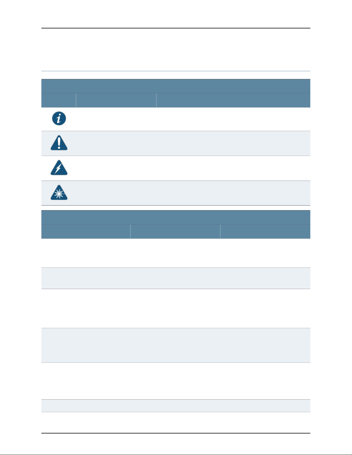
Notice Icons
DescriptionMeaningIcon
Indicates important features or instructions.Informational note
Caution
Text and Syntax Conventions
Fixed-width text like this
Italic text like this
Indicates a situation that might result in loss of data or hardware
damage.
Alerts you to the risk of personal injury or death.Warning
Alerts you to the risk of personal injury from a laser.Laser warning
Represents text that you type.Bold text like this
Represents output that appears on the
terminal screen.
•
Introduces important new terms.
•
Identifies book names.
•
Identifies RFC and Internet drafttitles.
ExamplesDescriptionConvention
To enter configuration mode, type the
configure command:
user@host> configure
user@host> show chassis alarms
No alarms currently active
•
A policy term is a named structurethat
defines match conditions and actions.
•
Junos OS System Basics Configuration
Guide
•
RFC 1997, BGP Communities Attribute
Italic text like this
Plain text like this
Represents variables (options for which
you substitute a value) in commands or
configuration statements.
Represents names of configuration
statements, commands, files, and
directories; IP addresses; configuration
hierarchy levels; or labels on routing
platform components.
Configure the machine’s domain name:
[edit]
root@# set system domain-name
domain-name
•
To configure a stub area, include the
stub statement at the [edit protocols
ospf area area-id] hierarchy level.
•
The console port is labeled CONSOLE.
stub <default-metric metric>;Enclose optional keywords or variables.< > (angle brackets)
Copyright © 2010, Juniper Networks, Inc.xviii
Page 19

Text and Syntax Conventions
About This Topic Collection
ExamplesDescriptionConvention
| (pipe symbol)
# (pound sign)
[ ] (square brackets)
Indention and braces ( { } )
; (semicolon)
J-Web GUI Conventions
Bold text like this
Indicatesa choice between the mutually
exclusivekeywordsor variableson either
side of the symbol. The set of choices is
often enclosed in parentheses for clarity.
same line as the configurationstatement
to which it applies.
Enclose a variable for which you can
substitute one or more values.
Identify a level in the configuration
hierarchy.
Identifies a leaf statement at a
configuration hierarchy level.
Represents J-Web graphical user
interface (GUI) items you click or select.
broadcast | multicast
(string1 | string2 | string3)
rsvp { # Required for dynamic MPLS onlyIndicates a comment specified on the
community name members [
community-ids ]
[edit]
routing-options {
static {
route default {
nexthop address;
retain;
}
}
}
•
In the Logical Interfaces box, selectAll
Interfaces.
•
To cancel the configuration, click
Cancel.
> (bold right angle bracket)
Documentation Feedback
We encourage you to provide feedback, comments, and suggestions so that we can
improve the documentation. Send e-mail to techpubs-comments@juniper.net with the
following:
•
Document URL or title
•
Page number if applicable
•
Software version
•
Your name and company
Separates levels in a hierarchy of J-Web
selections.
In the configuration editor hierarchy,
select Protocols>Ospf.
xixCopyright © 2010, Juniper Networks, Inc.
Page 20

Complete Hardware Guide for EX2200 Ethernet Switches
Requesting Technical Support
Technicalproduct support is availablethrough the Juniper Networks Technical Assistance
Center (JTAC). If you are a customer with an active J-Care or JNASC support contract,
or are covered under warranty, and need post-sales technical support, you can access
our tools and resources online or open a case with JTAC.
•
JTAC policies—For a complete understanding of our JTAC procedures and policies,
review the JTAC User Guide located at
http://www.juniper.net/us/en/local/pdf/resource-guides/7100059-en.pdf .
•
Product warranties—For product warranty information, visit
http://www.juniper.net/support/warranty/ .
•
JTAC hours of operation—The JTAC centers have resources available 24 hours a day,
7 days a week, 365 days a year.
Self-Help Online Tools and Resources
For quick and easy problem resolution, Juniper Networks has designed an online
self-service portal called the Customer Support Center (CSC) that provides you with the
following features:
•
Find CSC offerings: http://www.juniper.net/customers/support/
•
Search for known bugs: http://www2.juniper.net/kb/
•
Find product documentation: http://www.juniper.net/techpubs/
•
Find solutions and answer questions using our Knowledge Base: http://kb.juniper.net/
•
Download the latest versions of software and review release notes:
http://www.juniper.net/customers/csc/software/
•
Search technical bulletins for relevant hardware and software notifications:
https://www.juniper.net/alerts/
•
Join and participate in the Juniper Networks Community Forum:
http://www.juniper.net/company/communities/
•
Open a case online in the CSC Case Management tool: http://www.juniper.net/cm/
To verify service entitlement by product serial number,use our Serial Number Entitlement
(SNE) Tool: https://tools.juniper.net/SerialNumberEntitlementSearch/
Opening a Case with JTAC
You can open a case with JTAC on the Web or by telephone.
•
Use the Case Management tool in the CSC at http://www.juniper.net/cm/ .
•
Call 1-888-314-JTAC (1-888-314-5822 toll-free in the USA, Canada, and Mexico).
For international or direct-dial options in countries without toll-free numbers, see
http://www.juniper.net/support/requesting-support.html .
Copyright © 2010, Juniper Networks, Inc.xx
Page 21

PART 1
Switch and Components Overview and
Specifications
•
EX2200 Switch Overview on page 3
•
Component Descriptions on page 11
•
Component Specifications on page 19
1Copyright © 2010, Juniper Networks, Inc.
Page 22

Complete Hardware Guide for EX2200 Ethernet Switches
Copyright © 2010, Juniper Networks, Inc.2
Page 23

CHAPTER 1
EX2200 Switch Overview
•
EX2200 Switches Hardware Overview on page 3
•
EX2200 Switch Models on page 4
•
Chassis Physical Specifications for EX2200 Switches on page 5
•
Front Panel of an EX2200 Switch on page 5
•
Rear Panel of an EX2200 Switch on page 6
•
EX2200 Switch Hardware and CLI Terminology Mapping on page 7
EX2200 Switches Hardware Overview
Juniper Networks EX Series Ethernet Switches provide scalable connectivity for the
enterprise market, including branch offices, campus locations, and data centers. The
switches run under the Juniper Networks Junos operating system (Junos OS), which
provides Layer 2 and Layer 3 switching, routing, and security services. The same Junos
OS code base that runs on EX Series switches also runs on all Juniper Networks J Series,
M Series, MX Series, and T Series routers.
EX2200 Switches
Uplink Ports
•
EX2200 Switches on page 3
•
Uplink Ports on page 3
•
Power over Ethernet (PoE) Ports on page 4
Juniper Networks EX2200 Ethernet switches provide connectivity for low-density
environments.
EX2200 switches are available in models with either 24 or 48 built-in network ports and
four uplink ports, with Power over Ethernet (PoE) either available in all built-in network
ports or not available in any built-in network port. All models provide network ports that
have 10/100/1000Base-T Gigabit Ethernet connectors and four uplink ports. These
switches run under Junos OS for EX Series switches.
Each EX2200 switch has four uplink ports that support 1-gigabit small form-factor
pluggable (SFP) transceivers for use with fiber connections and copper connections.
See “Optical Interface Support in EX2200 Switches” on page 22.
3Copyright © 2010, Juniper Networks, Inc.
Page 24

Complete Hardware Guide for EX2200 Ethernet Switches
Power over Ethernet (PoE) Ports
PoEports provide electrical current to devices through the network cables so that separate
power cords for devices such as IP phones, wireless access points, and security cameras
are unnecessary. EX2200 switches are available with full (all 24 or 48 built-in network
ports) or no PoE capability. Full PoE models are primarily used in IP telephony
environments.
EX2200 switches running Junos OS Release 10.3 or later can supply up to 30 W to
individual PoE ports, supporting powered devices that comply with IEEE 802.3af (PoE)
and IEEE 802.3at (PoE+).
NOTE: IEEE 802.3at class 4 powered devices require category 5 or higher
Ethernet cables.
EX2200 switches running Junos OS Release 10.2 or earlier can supply up to 15.4 W to
individual PoE ports, supporting powered devices that comply with IEEE 802.3af (PoE).
Related
Documentation
EX2200 Switch Models on page 4•
• Site Preparation Checklist for EX2200 Switches on page 33
EX2200 Switch Models
The EX2200 switch is available with 24 or 48 built-in network ports with full (all 24 or
48 built-in network ports) or no Power over Ethernet (PoE) capability. Table 1 on page 4
lists the EX2200 switch models.
Table 1: EX2200 Switch Models
Related
Documentation
Front Panel of an EX2200 Switch on page 5•
• EX2200 Switches Hardware Overview on page 3
Maximum PoE Power
AvailablePorts in Which PoE Is AvailableAccess PortsModel
––24 Gigabit EthernetEX2200-24T-4G
405 WAll 24 ports24 Gigabit EthernetEX2200-24P-4G
––48 Gigabit EthernetEX2200-48T-4G
405 WAll 48 ports48 Gigabit EthernetEX2200-48P-4G
Copyright © 2010, Juniper Networks, Inc.4
Page 25

Chassis Physical Specifications for EX2200 Switches
The EX2200 switch chassis is a rigid sheet-metal structure that houses the hardware
components. Table 2 on page 5 summarizes the physical specifications of the EX2200
switch chassis.
Table 2: Physical Specifications of the EX2200 Switch Chassis
ValueDescription
1.75 in. (4.45 cm)Chassis height
•
Chassis width
Weight
17.5 in. (44.5 cm)
•
19 in. (48.2 cm) with mounting brackets attached
10.5 in. (26.7 cm)Chassis depth
•
EX2200-24T: 6 lb (2.7 kg)
•
EX2200-24P: 8 lb (3.6 kg)
•
EX2200-48T: 8 lb (3.6 kg)
•
EX2200-48P: 10 lb (4.5 kg)
Chapter 1: EX2200 Switch Overview
Related
Documentation
Rack Requirements for EX2200 Switches on page 39•
• Cabinet Requirements for EX2200 Switches on page 40
• Mounting an EX2200 Switch on page 53
• Installing and Connecting an EX2200 Switch on page 51
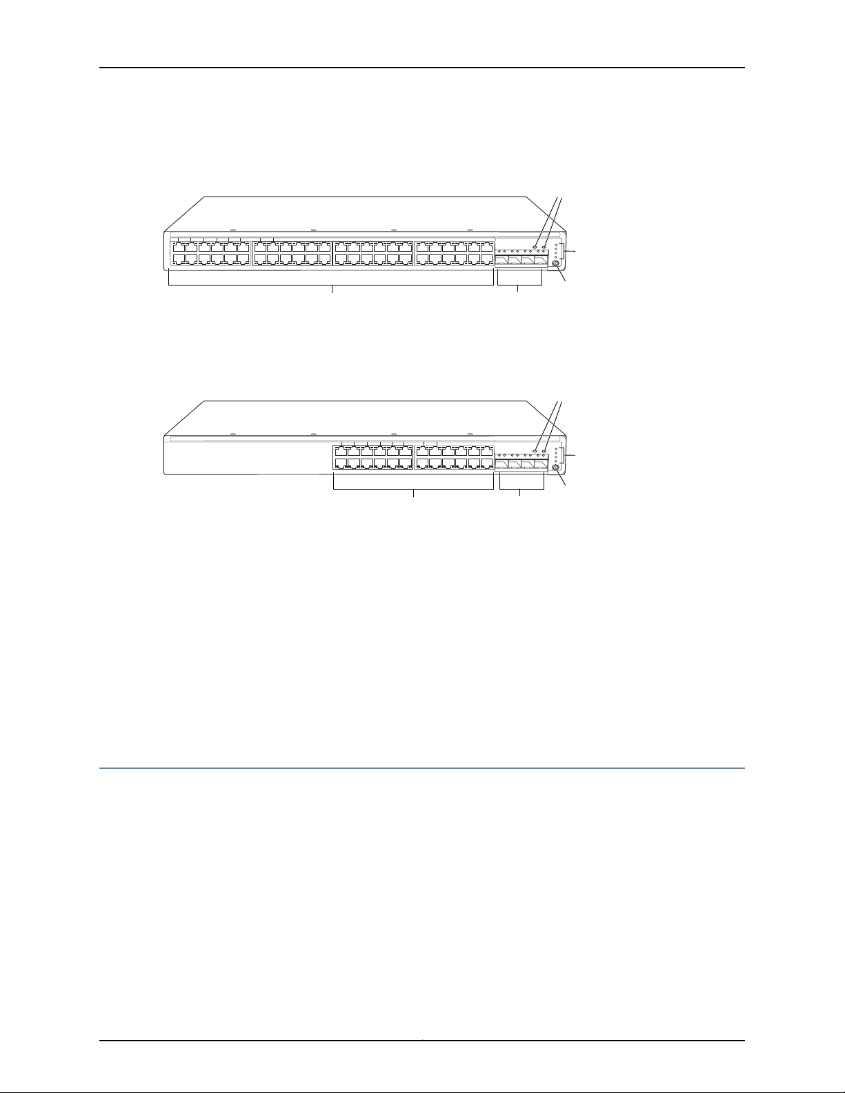
Front Panel of an EX2200 Switch
The front panel of an EX2200 switch consists of the following components:
•
Network ports—depending on the switch model, either of:
•
24 or 48 10/100/1000Base-T Gigabit Ethernet ports, with Powerover Ethernet (PoE)
not available in EX2200-24T and EX2200-48T
•
24 or 48 10/100/1000Base-T Gigabit Ethernet ports, with Powerover Ethernet (PoE)
available in EX2200-24P and EX2200-48P
•
4 built-in SFP uplink ports
•
2 chassis status LEDs
•
4 port status mode LEDs
•
Mode button
Figure 1 on page 6 shows the front panel of an EX2200 switch with 48 Gigabit Ethernet
ports. Figure 2 on page 6 shows the front panel of an EX2200 switch with 24 Gigabit
Ethernet ports.
5Copyright © 2010, Juniper Networks, Inc.
Page 26
01234567891011121314151617181920212223242526272829303132333435363738394041424344
45
0 1 2
SYS
ALM
SPD
DX
EN
POE
3
46
47
Network
ports
Port status mode LEDs
Mode
button
SFP
uplink
ports
Chassis
status
LEDs
g027000
012345678910111213141516171819202122
23
0 1 2
SYS
ALM
SPD
DX
EN
POE
3
Network
ports
Chassis
status
LEDs
g027002
SFP
uplink
ports
Port status mode LEDs
Mode
button
Complete Hardware Guide for EX2200 Ethernet Switches
Figure 1: Front Panel of an EX2200 Switch with 48 Gigabit Ethernet Ports
Figure 2: Front Panel of an EX2200 Switchwith 24 Gigabit Ethernet Ports
Related
Documentation
Chassis Status LEDs in EX2200 Switches on page 11•
• Network Port and Uplink Port LEDs in EX2200 Switches on page 12
• Network Port Connector Pinout Information for an EX2200 Switch on page 20
• Rear Panel of an EX2200 Switch on page 6
• Installing a Transceiver in an EX Series Switch on page 65
• Removing a Transceiver from an EX Series Switch on page 95
• Installing and Connecting an EX2200 Switch on page 51
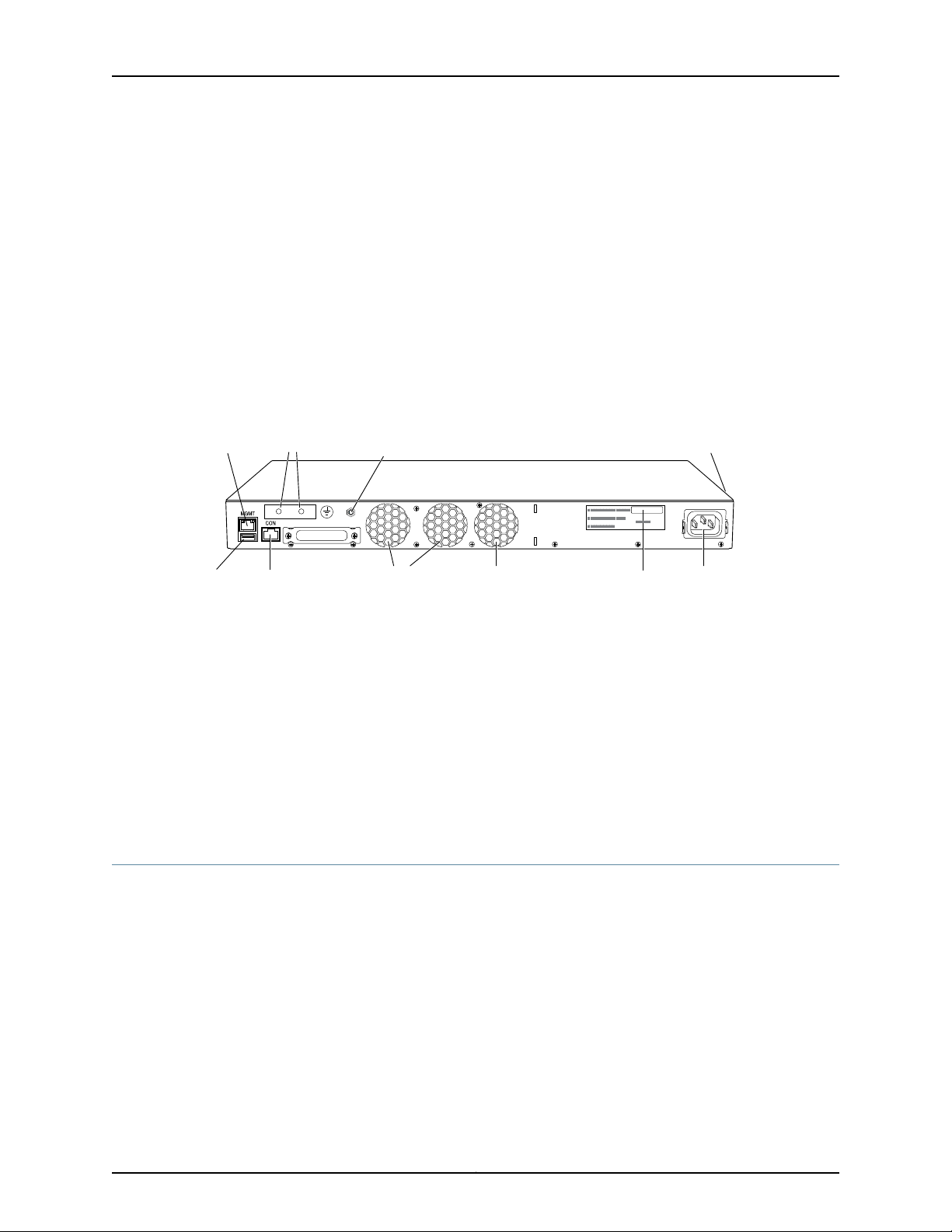
Rear Panel of an EX2200 Switch
The rear panel of the EX2200 switch consists of the following components:
•
Management Ethernet port
•
USB port
•
Console port
•
Protective earthing terminal
•
ESD point
•
Air exhaust
Copyright © 2010, Juniper Networks, Inc.6
Page 27
g027001
USB
port
Management
Ethernet port
Console
port
Protective
earthing terminal
Air exhaust without fan
(closed on non-PoE models)
Air exhaust
with fan
AC power
cord inlet
ESD
point
EX2200-24-4G REV: X1
750-026464 REV: X3
MAC:00:23:9C:oE:19:00
Mfg.Date
20090227
MADEIN CHINA
Serial number
ID label
Air intake with fan for power supply
(fan on PoE models only)
Chapter 1: EX2200 Switch Overview
•
Serial number ID label
•
AC power cord inlet
Figure 3 on page 7 shows the rear panel of an EX2200 switch.
All EX2200 switches have three exhaust openings on the rear panel. The two leftmost
exhaust openings have fans behind them and are open. The rightmost exhaust opening
is open on Power over Ethernet (PoE) models and closed on non-PoE models. On PoE
models, this opening exhausts the air from the fan at the air intake for the power supply
on the side panel.
The power cord retainer clips extend out of the chassis by 3 in.
Figure 3: Rear Panel of an EX2200 Switch
Related
Documentation
Front Panel of an EX2200 Switch on page 5•
• USB Port Specifications for an EX Series Switch on page 19
• Cooling System and Airflow in an EX2200 Switch on page 15
• Power Supply in EX2200 Switches on page 14
• Prevention of Electrostatic Discharge Damage on EX Series Switches on page 142
• Connecting Earth Ground to an EX Series Switch on page 67
• Installing and Connecting an EX2200 Switch on page 51
EX2200 Switch Hardware and CLI Terminology Mapping
This topic describes the hardware terms used in EX2200 switch documentation and the
corresponding terms used in the Junos OS command line interface (CLI). See Table 3 on
page 8.
7Copyright © 2010, Juniper Networks, Inc.
Page 28

Complete Hardware Guide for EX2200 Ethernet Switches
Table 3: CLI Equivalents of Terms Used in Documentation for EX2200 Switches
Chassis
FPC (n)
PIC (n)
•
EX2200-24T-4G
•
EX2200-24P-4G
•
EX2200-48T-4G
•
EX2200-48P-4G
the Flexible PIC
Concentrator (FPC)
One of the following:
•
EX2200-24T-4G
•
EX2200-24P-4G
•
EX2200-48T-4G
•
EX2200-48P-4G
Abbreviated name of
the Physical Interface
Card (PIC)
Value of n is always 0.Abbreviated name of
n is a value in the range
of 0-1.
Item in
DocumentationValue (CLI)Description (CLI)Hardware Item (CLI)
Switch chassis–One of the following:
The switch does not
have actual FPCs. In
this case, FPC refers to
the switch itself.
The switch does not
have actual PIC
devices; see entries for
PIC 0 through PIC 1 for
the equivalent item on
the switch.
Additional
Information
“Chassis Physical
Specifications for
EX2200 Switches” on
page 5
Understanding
Interface Naming
Conventions on EX
Series Switches
Understanding
Interface Naming
Conventions on EX
Series Switches
Xcvr (n)
•
24x 10/100/1000
Base-T
•
48x 10/100/1000
Base-T
Abbreviated name of
the transceiver
PIC 0One of the following:
PIC 14x GE SFP
to the number of the
port in which the
transceiver is installed.
Built-in network ports
on the front panel of
the switch
Built-in uplink ports on
the front panel of the
switch
Optical transceiversn is a value equivalent
AC power supplyValue of n is always 0.Built-in power supplyPower supply (n)
Fan tray–Fan trayFan tray
“Front Panel of an
EX2200 Switch” on
page 5
“Front Panel of an
EX2200 Switch” on
page 5
“Optical Interface
Support in EX2200
Switches” on page 22
“Power Supply in
EX2200 Switches” on
page 14
“Cooling System and
Airflow in an EX2200
Switch” on page 15
Copyright © 2010, Juniper Networks, Inc.8
Page 29

Chapter 1: EX2200 Switch Overview
Related
Documentation
• EX Series Switches Hardware and CLI Terminology Mapping
• EX2200 Switches Hardware Overview on page 3
9Copyright © 2010, Juniper Networks, Inc.
Page 30

Complete Hardware Guide for EX2200 Ethernet Switches
Copyright © 2010, Juniper Networks, Inc.10
Page 31

CHAPTER 2
g027003
0 1 2
SYS
ALM
SPD
DX
EN
POE
3
Chassis
status LEDs
Component Descriptions
•
Chassis Status LEDs in EX2200 Switches on page 11
•
Network Port and Uplink Port LEDs in EX2200 Switches on page 12
•
Management Port LEDs in EX2200 Switches on page 14
•
Power Supply in EX2200 Switches on page 14
•
Cooling System and Airflow in an EX2200 Switch on page 15
Chassis Status LEDs in EX2200 Switches
The front panel of an EX2200 switch has two chassis status LEDs labeled SYS and ALM
on the far right side of the panel, above the uplink ports (see Figure 4 on page 11).
Figure 4: Chassis Status LEDs in an EX2200 Switch
Table 4 on page 11 describes the chassis status LEDs in an EX2200 switch, their colors
and states, and the status they indicate.
Table 4: Chassis Status LEDs in an EX2200 Switch
State and DescriptionColorLED Label
There is no alarm.UnlitALM
There is a minor alarm.Amber
There is a major alarm.Red
GreenSYS
A major alarm (red) indicates a critical error condition that requires immediate action.
•
•
•
On steadily—The switch is functioning normally.
Blinking—The switch is booting.
Off—The switch is off.
11Copyright © 2010, Juniper Networks, Inc.
Page 32

012345678910111213141516171819202122
23
g027005
0
1
Link/Activity LED Status LED
g027007
0 1 2
SYS
ALM
SPD
DX
EN
POE
3
Port 1 Port 2 Port 3
Mode
button
Link/Activity
LED
Status
LED
Port 0
Port status
mode LEDs
Complete Hardware Guide for EX2200 Ethernet Switches
A minor alarm (amber) indicates a noncritical condition that requires monitoring or
maintenance. A minor alarm that is left unchecked might cause interruption in service or
performance degradation.
Both LEDs can be lit simultaneously.
You can view the colors of the two LEDs remotely through the CLI by issuing the
operational mode command show chassis led.
Related
Documentation
Front Panel of an EX2200 Switch on page 5•
• Checking Active Alarms with the J-Web Interface
• Understanding Alarm Types and Severity Levels on EX Series Switches
Network Port and Uplink Port LEDs in EX2200 Switches
Each network port and uplink port on the front panel of an EX2200 switch has two LEDs
that indicate link/activity and port status. See Figure 5 on page 12 and Figure 6 on page 12.
Figure 5: LEDs on the Network Ports on the Front Panel
Figure 6: LEDs on the Uplink Ports and Port Status Mode LEDs
Table 5: Link/Activity LED on the Network Ports and Uplink Ports in EX2200 Switches
Table 5 on page 12 describes the Link/Activity LED.
State and DescriptionColorLED
•
GreenLink/Activity
Blinking—The port and the link are active, and there is link activity.
•
On steadily—The port and the link are active, but there is no link activity.
•
Off—The port is not active.
Copyright © 2010, Juniper Networks, Inc.12
Page 33

Chapter 2: Component Descriptions
The LEDs labeled Status LED in Figure 5 on page 12 and Figure 6 on page 12 indicate the
status of one of the four port parameters—speed, duplex mode, administrative status,
and Power over Ethernet (PoE) status. Use the mode button below the POE LED on the
far right side of the front panel to toggle the Status LED to show the different port
parameters. You can tell which port parameter is indicated by the Status LED by seeing
which port status mode LED (SPD, DX, EN, and POE) is lit. (See Figure 6 on page 12).
Table 6 on page 13 describes the Status LED.
Table 6: Status LED on the Network Ports and Uplink Ports in EX2200 Switches
State and DescriptionPort Parameters
Speed
Duplex mode
Administrative status
PoE status
Indicates the speed. The speed indicators for network ports are:
•
One blink per second—10 Mbps
•
Two blinks per second—100 Mbps
•
Three blinks per second—1000 Mbps
The speed indicators for uplink ports are:
•
On steadily—1000 Mbps
•
Off—10/100 Mbps
Indicates the duplex mode. The status indicators are:
•
On steadily—Port is set to full-duplex mode.
•
Off—Port is set to half-duplex mode.
Indicates the administrative status. The status indicators are:
•
On steadily—Port is administratively enabled.
•
Off—Port is administratively disabled.
Indicates the PoE status. The status indicators for network ports are:
•
On steadily—PoE is availableon the port, a device that draws power from the port
is connected to the port, and the device is drawing power from the port.
•
Blinking—PoEis availableon the port, but no power is drawn from the port because
of one of the following:
•
No device that draws power from the port is connected to the port.
•
A device that draws power from the port is connectedto the port, but the device
is not drawing any power from the port.
•
Off—PoE is not available on the port.
PoE is not available on uplink ports; therefore,the LED for those ports is always unlit.
Related
Documentation
You can tell which port parameter is indicated by the Status LED on network ports and
uplink ports by issuing the operational mode command show chassis led.
Front Panel of an EX2200 Switch on page 5•
• Configuring Gigabit Ethernet Interfaces (CLI Procedure)
• Configuring Gigabit Ethernet Interfaces (J-Web Procedure)
13Copyright © 2010, Juniper Networks, Inc.
Page 34

g027006
Link/Activity
LED
Status
LED
Complete Hardware Guide for EX2200 Ethernet Switches
Management Port LEDs in EX2200 Switches
The management port on the rear panel of an EX2200 switch has two LEDs that indicate
link/activity and port status (see Figure 7 on page 14).
Figure 7: LEDs on the Management Port on an EX2200 Switch
Table 7 on page 14 describes the Link/Activity LED.
Table 7: Link/Activity LED on the Management Port on an EX2200 Switch
State and DescriptionColorLED
•
GreenLink/Activity
Blinking—The port and the link are active, and there is link
activity.
•
On steadily—The port and the link are active, but there is no
link activity.
•
Off—The port is not active.
Table 8 on page 14 describes the Status LED.
Table 8: Status LED on the Management Port on an EX2200 Switch
State and DescriptionColorLED
Indicates the speed. The speed indicators are:
•
One blink per second—10 Mbps
•
Two blinks per second—100 Mbps
Related
Documentation
GreenStatus
Connectingan EX Series Switchto a Network for Out-of-Band Management on page 74•
Power Supply in EX2200 Switches
The power supply in EX2200 switches is built in along the rear panel of the chassis, with
an AC power cord inlet on the rear panel to connect power to the switch.
Copyright © 2010, Juniper Networks, Inc.14
Page 35

Table 9 on page 15 lists the power consumed by each EX2200 switch model. The
maximum power available on a PoE port is 30 W for switches running Junos OS Release
10.3 or later and 15.4 W for switches running Junos OS Release 10.2 or earlier.
Table 9: Power Consumed by EX2200 Switches
Chapter 2: Component Descriptions
Maximum Power
Consumed by the Switch
drawn)
drawn)
Related
Documentation
Number of PoE-Enabled
PortsModel Number
24EX2200-24P
48EX2200-48P
AC Power Cord Specifications for EX2200 Switches on page 47•
• Rear Panel of an EX2200 Switch on page 6
• Power Specifications for EX2200 Switches on page 47
• Connecting AC Power to an EX2200 Switch on page 73
• Connecting Earth Ground to an EX Series Switch on page 67
Cooling System and Airflow in an EX2200 Switch
Maximum PoE Power
Available
–50 W–EX2200-24T
405 W60 W (when no PoE power is
–76 W–EX2200-48T
405 W91 W (when no PoE power is
The cooling systemin an EX2200 switch consists of two fans along the rear of the chassis
that provide side-to-rear chassis cooling. In switch models with network ports in which
PoE is available, there is an additional fan in the power supply.
Figure 8 on page 16 shows the airflow in an EX2200 switch with network ports in which
PoE is not available.
15Copyright © 2010, Juniper Networks, Inc.
Page 36

g027021
Chassis rear
Chassis front
Fans
g027008
Chassis rear
Chassis front
Fans Fan
Complete Hardware Guide for EX2200 Ethernet Switches
Figure 8: Airflow Through Non-PoE Models of EX2200 Switches
Figure 9 on page 16 shows the airflow in an EX2200 switch with network ports in which
PoE is available.
Figure 9: Airflow Through PoE Models of EX2200 Switches
Under normal operating conditions, the fans operate at reduced speed to reduce noise.
Temperature sensors in the chassis monitor the temperature within the chassis. If any
fan fails or if the temperature inside the chassis rises above the threshold, the switch
raises an alarm and all functioning fans operate at a higher speed than normal. If the
Copyright © 2010, Juniper Networks, Inc.16
Page 37

Chapter 2: Component Descriptions
temperature inside the chassis rises above the threshold, the switch shuts down
automatically.
Related
Documentation
• Rear Panel of an EX2200 Switch on page 6
• Chassis Status LEDs in EX2200 Switches on page 11
• Understanding Alarm Types and Severity Levels on EX Series Switches
• Prevention of Electrostatic Discharge Damage on EX Series Switches on page 142
17Copyright © 2010, Juniper Networks, Inc.
Page 38

Complete Hardware Guide for EX2200 Ethernet Switches
Copyright © 2010, Juniper Networks, Inc.18
Page 39

CHAPTER 3
Component Specifications
•
USB Port Specifications for an EX Series Switch on page 19
•
Network Port Connector Pinout Information for an EX2200 Switch on page 20
•
Console Port Connector Pinout Information for an EX Series Switch on page 21
•
Management Port Connector Pinout Information for an EX2200 Switch on page 22
•
Optical Interface Support in EX2200 Switches on page 22
USB Port Specifications for an EX Series Switch
The following Juniper Networks USB flash drives have been tested and are officially
supported for the USB port on all EX Series switches:
•
RE-USB-1G-S
•
RE-USB-2G-S
•
RE-USB-4G-S
CAUTION: Any USB memory product not listed as supported for EX Series
switches has not been tested by Juniper Networks. The use of any
unsupported USB memory product could expose your EX Series switch to
unpredictablebehavior.Juniper Networks TechnicalAssistanceCenter (JTAC)
can provide only limited support for issues related to unsupported hardware.
We strongly recommend that you use only supported USB flash drives.
All USB flash drives used on EX Series switches must have the following features:
•
USB 2.0 or later.
•
Formatted with a FAT or MS-DOS file system.
•
If the switch is running Junos OS Release 9.5 or earlier, the formatting method must
use a master boot record. Microsoft Windows formatting, by default, does not use a
master boot record. See the documentation for your USB flash drive for information
on how your USB flash drive is formatted.
19Copyright © 2010, Juniper Networks, Inc.
Page 40

Complete Hardware Guide for EX2200 Ethernet Switches
Related
Documentation
See Rear Panel of an EX2200 Switch on page 6 for port location.•
• See Rear Panel of an EX3200 Switch for port location.
• See Rear Panel of an EX4200 Switch for port location.
• See Front Panel of an EX4500 Switch for port location.
• See Switch Fabric and Routing Engine (SRE) Module in an EX8208 Switch for port
location.
• See Routing Engine (RE) Module in an EX8216 Switch for port location.
• Booting an EX Series Switch Using a Software Package Stored on a USB Flash Drive
Network Port Connector Pinout Information for an EX2200 Switch
A network port on an EX2200 switch uses an RJ-45 connector to connect to a device.
The port uses an autosensing RJ-45 connector to support a 10/100/1000Base-T
connection. Two LEDs on the port indicate link/activity on the port and the port status.
See “Network Port and Uplink Port LEDs in EX2200 Switches” on page 12.
Table 10 on page 20 provides the pinout information for the RJ-45 connector. An RJ-45
cable, with a connector attached, is supplied with the switch.
Table 10: Network Port Connector Pinout Information for EX2200 Switches
DescriptionSignalPin
TRP1+1
TRP1-2
TRP2+3
TRP2-6
Transmit/receive data pair 1
Negative Vport (in PoE models)
Transmit/receive data pair 1
Negative Vport (in PoE models)
Transmit/receive data pair 2
Positive Vport (in PoE models)
Transmit/receive data pair 3TRP3+4
Transmit/receive data pair 3TRP3-5
Transmit/receive data pair 2
Positive Vport (in PoE models)
Transmit/receive data pair 4TRP4+7
Transmit/receive data pair 4TRP4-8
Copyright © 2010, Juniper Networks, Inc.20
Page 41

Chapter 3: Component Specifications
Related
Front Panel of an EX2200 Switch on page 5•
Documentation
Console Port Connector Pinout Information for an EX Series Switch
The console port on an EX Series switch is an RS-232 serial interface that uses an RJ-45
connector to connect to a console management device. The default baud rate for the
console port is 9600 baud.
Table 11 on page 21 provides the pinout information for the RJ-45 console connector. An
RJ-45 cable and an RJ-45 to DB-9 serial port adapter are supplied with the switch.
NOTE: If your laptop or PC does not have a DB-9 male connector pin and you
want to connect your laptop or PC directly to an EX Series switch, use a
combination of the RJ-45 to DB-9 female adapter supplied with the switch
and a USB to DB-9 male adapter. You must provide the USB to DB-9 male
adapter.
Table 11: EX Series Switches Console Port Connector Pinout Information
DescriptionSignalPin
Request to sendRTS Output1
Related
Documentation
Data terminal readyDTR Output2
Transmit dataTxD Output3
Signal groundSignal Ground4
Signal groundSignal Ground5
Receive dataRxD Input6
Data carrier detectCD Input7
Clear to sendCTS Input8
See Rear Panel of an EX2200 Switch on page 6 for port location.•
• See Rear Panel of an EX3200 Switch for port location.
• See Rear Panel of an EX4200 Switch for port location.
• See Front Panel of an EX4500 Switch for port location.
• See Switch Fabric and Routing Engine (SRE) Module in an EX8208 Switch for port
location.
• See Routing Engine (RE) Module in an EX8216 Switch for port location.
21Copyright © 2010, Juniper Networks, Inc.
Page 42

Complete Hardware Guide for EX2200 Ethernet Switches
• Connecting an EX Series Switch to a Management Console on page 76
Management Port Connector Pinout Information for an EX2200 Switch
The management port on an EX2200 switch uses an RJ-45 connector to connect to a
management device for out-of-band management.
The port uses an autosensing RJ-45 connector to support a 10/100Base-T connection.
Two LEDs on the port indicate link/activity on the port and the administrative status of
the port. See “Management Port LEDs in EX2200 Switches” on page 14.
Table 12 on page 22 provides the pinout information for the RJ-45 connector for the
managementport. An RJ-45 cable,with a connectorattached,is supplied with the switch.
Table 12: Management Port Connector Pinout Information for EX2200 Switches
DescriptionSignalPin
Transmit/receive data pair 1TRP1+1
Related
Documentation
See Rear Panel of an EX2200 Switch on page 6 for port location.•
• Connecting an EX Series Switchto a Networkfor Out-of-Band Management on page 74
Optical Interface Support in EX2200 Switches
Uplink ports on the front panel in EX2200 switches support SFP transceivers. This topic
describes the optical interfaces supported for those transceivers. It also lists the copper
interface supported for the SFP transceivers.
NOTE: Use only optical transceivers and optical connectors purchased from
Juniper Networks for your EX2200 switch.
The two tables in this topic describe the optical interface support over single-mode
fiber-optic (SMF) and multimode fiber-optic (MMF) cables and over the copper interface
for SFP transceivers:
Transmit/receive data pair 1TRP1-2
Transmit/receive data pair 2TRP2+3
Transmit/receive data pair 2TRP2-6
•
Table13 on page 23—Optical interface support and copper interfacesupport for Gigabit
Ethernet SFP transceivers
•
Table 14 on page 27—Optical interface support for Fast Ethernet SFP transceivers
Copyright © 2010, Juniper Networks, Inc.22
Page 43

Chapter 3: Component Specifications
Table 13: Optical Interface Support and Copper Interface Support for Gigabit Ethernet SFP
Transceivers in EX2200 Switches
ValueSpecificationEthernet Standard
EX-SFP-1GE-TModel Number1000Base-T
10/100/1000 MbpsRate
RJ-45Connector Type
–Transmitter Wavelength
–Minimum Launch Power
–Maximum Launch Power
–Minimum Receiver Sensitivity
–Maximum Input Power
–Core/Cladding Size
–Modal Bandwidth
100 m (328 ft)Distance
Junos OS for EX Series switches, Release 10.1 or laterSoftware required
23Copyright © 2010, Juniper Networks, Inc.
Page 44

Complete Hardware Guide for EX2200 Ethernet Switches
Table 13: Optical Interface Support and Copper Interface Support for Gigabit Ethernet SFP
Transceivers in EX2200 Switches (continued)
ValueSpecificationEthernet Standard
EX-SFP-1GE-SXModel Number1000Base-SX
1000 MbpsRate
LCConnector Type
DualFiber Count
850 nmTransmitter Wavelength
–9.5 dBmMinimum Launch Power
–3 dBmMaximum Launch Power
Distance
–21 dBmMinimum Receiver Sensitivity
0 dBmMaximum Input Power
MMFFiber Type
220 m
(722 ft)
Junos OS for EX Series switches, Release 10.1 or laterSoftware required
275 m
(902 ft)
500 m
(1640 ft)
50/125 µm50/125 µm62.5/125 µm62.5/125 µmCore/Cladding Size
OM2–OM1FDDIFiber Grade
500 MHz/km400 MHz/km200 MHz/km160 MHz/kmModal Bandwidth
550 m
(1804 ft)
Copyright © 2010, Juniper Networks, Inc.24
Page 45

Chapter 3: Component Specifications
Table 13: Optical Interface Support and Copper Interface Support for Gigabit Ethernet SFP
Transceivers in EX2200 Switches (continued)
ValueSpecificationEthernet Standard
EX-SFP-1GE-LXModel Number1000Base-LX
1000 MbpsRate
LCConnector Type
DualFiber Count
1310 nmTransmitter Wavelength
–9.5 dBmMinimum Launch Power
–3 dBmMaximum Launch Power
–25 dBmMinimum Receiver Sensitivity
–3 dBmMaximum Input Power
SMFFiber Type
9/125 µmCore/Cladding Size
–Modal Bandwidth
10 km (6.2 miles)Distance
Junos OS for EX Series switches, Release 10.1 or laterSoftware required
25Copyright © 2010, Juniper Networks, Inc.
Page 46

Complete Hardware Guide for EX2200 Ethernet Switches
Table 13: Optical Interface Support and Copper Interface Support for Gigabit Ethernet SFP
Transceivers in EX2200 Switches (continued)
ValueSpecificationEthernet Standard
EX-SFP-1GE-LHModel Number1000Base-LH (or
1000Base-ZX)
1000 MbpsRate
LCConnector Type
DualFiber Count
1550 nmTransmitter Wavelength
–2 dBmMinimum Launch Power
5 dBmMaximum Launch Power
–25 dBmMinimum Receiver Sensitivity
–3 dBmMaximum Input Power
SMFFiber Type
9/125 µmCore/Cladding Size
–Modal Bandwidth
70 km (43.5 miles)Distance
Junos OS for EX Series switches, Release 10.1 or laterSoftware required
Copyright © 2010, Juniper Networks, Inc.26
Page 47

Chapter 3: Component Specifications
Table 14: Optical Interface Support for Fast Ethernet SFP Transceivers in EX2200 Switches
ValueSpecificationEthernet Standard
EX-SFP-1FE-FXModel Number100Base-FX
100 MbpsRate
LCConnector Type
DualFiber Count
1310 nmTransmitter Wavelength
–20 dBmMinimum Launch Power
–14 dBmMaximum Launch Power
–32.5 dBmMinimum Receiver Sensitivity
–8 dBmMaximum Input Power
MMFFiber Type
62.5/125 µmCore/Cladding Size
FDDI/OM1Fiber Grade
500 Mhz/kmModal Bandwidth
2 km (1.2 miles)Distance
Junos OS for EX Series switches, Release 10.1 or laterSoftware required
27Copyright © 2010, Juniper Networks, Inc.
Page 48

Complete Hardware Guide for EX2200 Ethernet Switches
Table 14: Optical Interface Support for Fast Ethernet SFP Transceivers in EX2200
Switches (continued)
ValueSpecificationEthernet Standard
EX-SFP-FE20KT13R15Model Number100Base-BX-U
100 MbpsRate
LCConnector Type
SingleFiber Count
1310 nmTransmitter Wavelength
1550 nmReceiver Wavelength
–14 dBmMinimum Launch Power
–8 dBmMaximum Launch Power
–45 dBmMinimum Receiver Sensitivity
–8 dBmMaximum Input Power
SMFFiber Type
9/125 µmCore/Cladding Size
–Modal Bandwidth
20 km (12.4 miles)Distance
Junos OS for EX Series switches, Release 10.1 or laterSoftware required
Copyright © 2010, Juniper Networks, Inc.28
Page 49

Chapter 3: Component Specifications
Table 14: Optical Interface Support for Fast Ethernet SFP Transceivers in EX2200
Switches (continued)
ValueSpecificationEthernet Standard
EX-SFP-FE20KT15R13Model Number100Base-BX-D
100 MbpsRate
LCConnector Type
SingleFiber Count
1550 nmTransmitter Wavelength
1310 nmReceiver Wavelength
–14 dBmMinimum Launch Power
Related
Documentation
–8 dBmMaximum Launch Power
–45 dBmMinimum Receiver Sensitivity
–8 dBmMaximum Input Power
SMFFiber Type
9/125 µmCore/Cladding Size
–Modal Bandwidth
20 km (12.4 miles)Distance
Junos OS for EX Series switches, Release 10.1 or laterSoftware required
• Front Panel of an EX2200 Switch on page 5
• Installing a Transceiver in an EX Series Switch on page 65
• Removing a Transceiver from an EX Series Switch on page 95
29Copyright © 2010, Juniper Networks, Inc.
Page 50

Complete Hardware Guide for EX2200 Ethernet Switches
Copyright © 2010, Juniper Networks, Inc.30
Page 51

PART 2
Planning for Switch Installation
•
Site Preparation on page 33
•
Mounting and Clearance Requirements on page 39
•
Cable Specifications on page 45
•
Planning Power Requirements on page 47
31Copyright © 2010, Juniper Networks, Inc.
Page 52

Complete Hardware Guide for EX2200 Ethernet Switches
Copyright © 2010, Juniper Networks, Inc.32
Page 53

CHAPTER 4
Site Preparation
•
Site Preparation Checklist for EX2200 Switches on page 33
•
General Site Guidelines for EX Series Switches on page 35
•
Site Electrical Wiring Guidelines for EX Series Switches on page 35
•
Environmental Requirements and Specifications for EX Series Switches on page 36
Site Preparation Checklist for EX2200 Switches
The checklist in Table 15 on page 33 summarizes the tasks you need to perform when
preparing a site for EX2200 switch installation.
Table 15: Site Preparation Checklist
Environment
Verify that environmental factors such as
temperatureand humidity do not exceedswitch
tolerances.
“Environmental Requirements and
Specificationsfor EX Series Switches”
on page 36
DatePerformed ByFor More InformationItem or Task
Power
Measure distance between external power
sources and switch installation site.
Locate sites for connection of system
grounding.
Calculate the power consumption and
requirements.
Hardware Configuration
Choose the number and types of switches you
want to install.
Rack or Cabinet
“Power Specifications for EX2200
Switches” on page 47
“EX2200 Switches Hardware
Overview” on page 3
33Copyright © 2010, Juniper Networks, Inc.
Page 54

Complete Hardware Guide for EX2200 Ethernet Switches
Table 15: Site Preparation Checklist (continued)
DatePerformed ByFor More InformationItem or Task
Verify that your rack or cabinet meets the
minimum requirements for the installation of
the switch.
Plan rack or cabinet location,including required
space clearances.
Secure the rack or cabinet to the floor and
building structure.
Wall
Verify that the wall meets the minimum
requirements for the installation of the switch.
Verifythat there is appropriate clearance in your
selected location.
Cables
Acquire cables and connectors:
•
Determine the number of cables needed
based on your planned configuration.
•
Review the maximum distance allowed for
each cable. Choose the length of cable based
on the distance between the hardware
components being connected.
“Rack Requirements for EX2200
Switches” on page 39
“Cabinet Requirements for EX2200
Switches” on page 40
“Clearance Requirements for Airflow
and Hardware Maintenance for
EX2200 Switches” on page 42
“Requirements for Mounting an
EX2200 Switch on a Desktopor Wall”
on page 42
“Clearance Requirements for Airflow
and Hardware Maintenance for
EX2200 Switches” on page 42
Plan the cable routing and management.
Related
Documentation
General Safety Guidelines and Warnings for EX Series Switches on page 113•
• General Site Guidelines for EX Series Switches on page 35
• Installing and Connecting an EX2200 Switch on page 51
• Mounting an EX2200 Switch on page 53
Copyright © 2010, Juniper Networks, Inc.34
Page 55

General Site Guidelines for EX Series Switches
Efficient device operation requires proper site planning and maintenance and proper
layout of the equipment, rack or cabinet (if used), and wiring closet.
To plan and create an acceptable operating environment for your device and prevent
environmentally caused equipment failures:
•
Keep the area around the chassis free from dust and conductive material, such as
metal flakes.
•
Followprescribed airflow guidelines to ensure that the cooling system functions properly
and that exhaust from other equipment does not blow into the intake vents of the
switch.
•
Follow the prescribed ESD prevention procedures to avoid damaging the equipment.
Static discharge can cause components to fail completely or intermittently over time.
•
Install the switch in a secure area, so that only authorized personnel can access the
switch.
Chapter 4: Site Preparation
Related
Documentation
Prevention of Electrostatic Discharge Damage on EX Series Switches on page 142•
• Clearance Requirements for Airflow and Hardware Maintenance for EX2200 Switches
on page 42
• Clearance Requirements for Airflow and Hardware Maintenance for EX3200 Switches
• Clearance Requirements for Airflow and Hardware Maintenance for EX4200 Switches
• Clearance Requirements for Airflow and Hardware Maintenance for EX4500 Switches
• ClearanceRequirementsfor Airflowand Hardware Maintenance for an EX8208 Switch
• Clearance Requirements for Airflow and Hardware Maintenance for an EX8216 Switch
• Environmental Requirements and Specifications for EX Series Switches on page 36
Site Electrical Wiring Guidelines for EX Series Switches
Table 16 on page36 describes the factors you must consider while planning the electrical
wiring at your site.
WARNING: It is particularly important to provide a properly grounded and
shielded environment and to use electrical surge-suppression devices.
35Copyright © 2010, Juniper Networks, Inc.
Page 56

Complete Hardware Guide for EX2200 Ethernet Switches
Table 16: Site Electrical Wiring Guidelines
GuidelinesSite Wiring Factor
Signaling limitations
Radio frequency interference
Electromagnetic compatibility
If your site experiences any of the following problems, consult
experts in electrical surge suppression and shielding:
•
Improperlyinstalledwires cause radio frequency interference
(RFI).
•
Damage from lightning strikes occurs when wires exceed
recommended distances or pass between buildings.
•
Electromagnetic pulses (EMPs) caused by lightning
damages unshielded conductors and electronic devices.
To reduce or eliminate radio frequency interference (RFI) from
your site wiring, do the following:
•
Use twisted-pair cable with a good distribution of grounding
conductors.
•
If you must exceed the recommended distances, use a
high-quality twisted-pair cable with one ground conductor
for each data signal when applicable.
If your site is susceptible to problems with electromagnetic
compatibility (EMC), particularly from lightning or radio
transmitters, seek expert advice.
Some of the problems caused by strong sources of
electromagnetic interference (EMI) are:
•
Destruction of the signal drivers and receivers in the switch
•
Electrical hazards as a result of power surges conducted
over the lines into the equipment
Related
Documentation
General Safety Guidelines and Warnings for EX Series Switches on page 113•
• General Electrical Safety Guidelines and Warnings for EX Series Switches on page 141
• Prevention of Electrostatic Discharge Damage on EX Series Switches on page 142
• Power Supply in EX2200 Switches on page 14
• Power Supply in EX3200 Switches
• Power Supply in EX4200 Switches
• AC Power Supply in EX4500 Switches
• DC Power Supply in EX4500 Switches
• AC Power Supply in an EX8200 Switch
• DC Power Supply in an EX8200 Switch
Environmental Requirements and Specifications for EX Series Switches
The switch must be installed in a rack or cabinet housed in a dry, clean, well-ventilated,
and temperature-controlled environment.
Copyright © 2010, Juniper Networks, Inc.36
Page 57

Chapter 4: Site Preparation
Ensure that these environmental guidelines are followed:
•
The site must be as dust-free as possible, because dust can clog air intake vents and
filters, reducing the efficiency of the switch cooling system.
•
Maintain ambient airflow for normal switch operation. If the airflow is blocked or
restricted, or if the intake air is too warm, the switch might overheat, leading to the
switch temperature monitor shutting down the switch to protect the hardware
components.
Table 17 on page 37 provides the required environmental conditions for normal switch
operation.
Table 17: EX Series Switch Environmental Tolerances
ToleranceDescription
No performance degradation to 10,000 feet (3048 meters)Altitude
Normal operation ensured in relative humidity range of 10% through 85%, noncondensingRelative humidity
Related
Documentation
•
Temperature
EX2200, EX3200, EX4200, and EX4500 switches: Normal operation ensured in temperature range of 32° F
through 113° F (0° C through 45° C)
•
EX8208 and EX8216 switches: Normal operation ensured in temperature range of 32° F through 104° F (0° C
through 40° C)
•
XRE200 External Routing Engines: Normal operation ensured in temperature range of 41° F through 104° F
(5° C through 40° C)
Complies with Zone 4 earthquake requirements as per GR-63, Issue 3.Seismic
NOTE: Install EX Series switches only in restricted areas, such as dedicated
equipment rooms and equipment closets, in accordancewith Articles110–16,
110–17, and 110–18 of the National Electrical Code, ANSI/NFPA 70.
• Clearance Requirements for Airflow and Hardware Maintenance for EX2200 Switches
on page 42
• Clearance Requirements for Airflow and Hardware Maintenance for EX3200 Switches
• Clearance Requirements for Airflow and Hardware Maintenance for EX4200 Switches
• Clearance Requirements for Airflow and Hardware Maintenance for EX4500 Switches
• ClearanceRequirementsfor Airflowand Hardware Maintenance for an EX8208 Switch
• Clearance Requirements for Airflow and Hardware Maintenance for an EX8216 Switch
37Copyright © 2010, Juniper Networks, Inc.
Page 58

Complete Hardware Guide for EX2200 Ethernet Switches
Copyright © 2010, Juniper Networks, Inc.38
Page 59

CHAPTER 5
Mounting and Clearance Requirements
•
Rack Requirements for EX2200 Switches on page 39
•
Cabinet Requirements for EX2200 Switches on page 40
•
Requirements for Mounting an EX2200 Switch on a Desktop or Wall on page 42
•
Clearance Requirements for Airflow and Hardware Maintenance for EX2200
Switches on page 42
Rack Requirements for EX2200 Switches
You can mount the switch on two-post racks or four-post racks.
Rack requirements consist of:
•
Rack type
•
Mounting bracket hole spacing
•
Rack size and strength
•
Rack connection to the building structure
Table 18 on page 39 provides the rack requirements and specifications for the switch.
Table 18: Rack Requirements and Specifications for the Switch
GuidelinesRack Requirement
Rack type
Mounting bracket hole
spacing
Use a two-post rack or a four-post rack. You can mount the switch on any two-post or four-post
rack that provides bracket holes or hole patterns spaced at 1 U (1.75 in./4.45 cm) increments and
that meets the size and strength requirements to support the weight.
A U is the standard rack unit defined in Cabinets, Racks, Panels, and Associated Equipment (document
number EIA-310–D) published by the Electronics Industry Association (http://www.eia.org).
The rack must meet the strength requirements to support the weight of the chassis.
The holes in the mounting brackets are spaced at 1 U (1.75 in. or 4.45 cm), so that the switch can
be mounted in any rack that provides holes spaced at that distance.
39Copyright © 2010, Juniper Networks, Inc.
Page 60

Complete Hardware Guide for EX2200 Ethernet Switches
Table 18: Rack Requirements and Specifications for the Switch (continued)
GuidelinesRack Requirement
•
Rack size and strength
Rack connection to
building structure
Ensure that the rack complies with one of these standards:
•
A 19-in. rack as defined in Cabinets, Racks, Panels, and Associated Equipment (document
number EIA-310–D) published by the ElectronicsIndustry Association (http://www.eia.org).
•
Ensure that the rack rails are spacedwidely enough to accommodate the switch chassis' external
dimensions . The outer edges of the front-mounting brackets extend the width of the chassis to
19 in. (48.2 cm).
•
The rack must be strong enough to support the weight of the switch.
•
Ensure that the spacing of rails and adjacent racks allows for the proper clearance around the
switch and rack.
•
Secure the rack to the building structure.
•
If earthquakes are a possibility in your geographical area, secure the rack to the floor.
•
Secure the rack to the ceiling brackets as well as wall or floor brackets for maximum stability.
One pair of mounting bracketsfor mounting the switch on two posts of a rack is supplied
with each switch. For mounting the switch on four posts of a rack or cabinet, you can
order a four-post rack-mount kit separately.
Related
Documentation
Chassis Physical Specifications for EX2200 Switches on page 5•
• Clearance Requirements for Airflow and Hardware Maintenance for EX2200 Switches
on page 42
• Rack-Mounting and Cabinet-Mounting Warnings for EX Series Switches on page 129
• Mounting an EX2200 Switch on Two Posts in a Rack or Cabinet on page 55
• Mounting an EX2200 Switch on Four Posts in a Rack or Cabinet on page 57
• Mounting an EX2200 Switch in a Recessed Position in a Rack or Cabinet on page 61
Cabinet Requirements for EX2200 Switches
You can mount the switch in a cabinet that contains a 19-in. rack.
Cabinet requirements consist of:
•
Cabinet size
•
Clearance requirements
•
Cabinet airflow requirements
Table 19 on page 41 provides the cabinet requirements and specifications for the switch.
Copyright © 2010, Juniper Networks, Inc.40
Page 61

Chapter 5: Mounting and Clearance Requirements
Table 19: Cabinet Requirements and Specifications for the Switch
GuidelinesCabinet Requirement
•
Cabinet size
Cabinet clearance
You can mount the switch in a cabinet that contains a 19-in.
rack as defined in Cabinets, Racks, Panels, and Associated
Equipment (document number EIA-310–D) published by
the Electronics Industry Association (http://www.eia.org).
NOTE: The rack must meet the strength requirements to
support the weight of the switch.
•
The minimum cabinet size must be able to accommodate
the maximum external dimensions of the switch.
•
The outer edges of the mounting brackets extend the width
of the chassis to 19 in. (48.3 cm).
•
The minimum total clearance inside the cabinet is 30 in.
(76.2cm) between the inside of the front door and the inside
of the rear door.
Cabinet airflow requirements
Related
Documentation
When you mount the switch in a cabinet, ensure that
ventilation through the cabinet is sufficient to prevent
overheating.
•
Ensure adequate cool air supply to dissipate the thermal
output of the switch or switches.
•
Ensure that the cabinet allows the chassis hot exhaust air
to exit the cabinet without recirculating into the switch. An
open cabinet (without a top or doors) that employs hot air
exhaust extraction from the top allows the best airflow
through the chassis. If the cabinet contains a top or doors,
perforationsin these elements assist with removing the hot
air exhaust.
•
Install the switch in the cabinet in a way that maximizes the
open space on the side of the chassis that has the hot air
exhaust. This maximizes the clearance for critical airflow.
•
Route and dress all cables to minimize the blockage of
airflow to and from the chassis.
•
Ensure that the spacing of rails and adjacent cabinetsallows
for the proper clearance around the switch and cabinet.
•
A cabinet largerthan the minimum required providesbetter
airflow and reduces the chance of overheating.
Chassis Physical Specifications for EX2200 Switches on page 5•
• Clearance Requirements for Airflow and Hardware Maintenance for EX2200 Switches
on page 42
• Rack-Mounting and Cabinet-Mounting Warnings for EX Series Switches on page 129
• Mounting an EX2200 Switch on Two Posts in a Rack or Cabinet on page 55
• Mounting an EX2200 Switch on Four Posts in a Rack or Cabinet on page 57
• Mounting an EX2200 Switch in a Recessed Position in a Rack or Cabinet on page 61
41Copyright © 2010, Juniper Networks, Inc.
Page 62

g027009
Mounting bracket
6" (15.2 cm)
for airflow
Rear of chassis
Front of chassis
17.5"
44.5 cm
10.5"
(26.7 cm)
Clearance
required for
maintenance
Clearance required
for maintenance
24" (61 cm)
6" (15.2 cm)
6" (15.2 cm)
for airflow
19"
(48.2 cm)
Complete Hardware Guide for EX2200 Ethernet Switches
Requirements for Mounting an EX2200 Switch on a Desktop or Wall
You can install the switch on a desktop or wall. When choosing a location, allow at least
6 in. (15.2 cm) of clearance between the front and back of the chassis and adjacent
equipment or walls.
Ensure that the wall onto which the switch is installed is stable and securely supported.
If you are mounting the switch in sheetrock (wall board with a gypsum plaster core) or
in wall board not backed by wall studs, use hollow wall anchors capable of supporting
the combined weight of two fully loaded chassis. Insert the screws into wall studs
wherever possible to provide added support for the chassis.
Use the wall-mount kit from Juniper Networks to mount the switch on a wall. The
wall-mount kit is not part of the standard package and needs to be ordered separately.
Related
Documentation
Clearance Requirements for Airflow and Hardware Maintenance for EX2200 Switches
•
on page 42
• Wall-Mounting Warnings for EX2200 Switches on page 134
• Mounting an EX2200 Switch on a Desk or Other Level Surface on page 54
• Mounting an EX2200 Switch on a Wall on page 61
Clearance Requirements for Airflow and Hardware Maintenance for EX2200 Switches
When planning the site for installing an EX2200 switch, you must allow sufficient
clearance around the installed switch (see Figure 10 on page 42).
Figure 10: Clearance Requirements for Airflow and Hardware Maintenance
for EX2200 Switches
The power cord retainer clips extend out of the rear of the chassis by 3 in.
•
Allow at least 6 in. (15.2 cm) of clearance on the side between devices that have fans
or blowers installed. Allow 2.8 in. (7 cm) between the side of the chassis and any
Copyright © 2010, Juniper Networks, Inc.42
Page 63

g027008
Chassis rear
Chassis front
Fans Fan
g027021
Chassis rear
Chassis front
Fans
Chapter 5: Mounting and Clearance Requirements
non-heat-producingsurfacesuch as a wall. For the cooling system to function properly,
the airflow around the chassis must be unrestricted.
Figure 11 on page 43 shows the airflow in an EX2200 switch with network ports in which
PoE is available. Figure 12 on page 43 shows the airflow in an EX2200 switch with
network ports in which PoE is not available.
Figure 11: Airflow Through PoE Models of EX2200 Switches
Figure 12: Airflow Through Non-PoE Models of EX2200 Switches
43Copyright © 2010, Juniper Networks, Inc.
Page 64

Complete Hardware Guide for EX2200 Ethernet Switches
•
If you are mounting an EX2200 switch in a rack or cabinet with other equipment, or if
you are placing it on the desktop or floor near other equipment, ensure that the exhaust
from other equipment does not blow into the intake vents of the chassis.
•
Leave at least 24 in. (61 cm) in front of the switch and 6 in. (15.2 cm) behind the switch.
For service personnel to remove and install hardware components, you must leave
adequate space at the front and back of the switch. NEBS GR-63 recommends that
you allow at least 30 in. (76.2 cm) in front of the rack or cabinet and 24 in. (61 cm)
behind the rack or cabinet.
Related
Documentation
• Rack Requirements for EX2200 Switches on page 39
• Cabinet Requirements for EX2200 Switches on page 40
• General Site Guidelines for EX Series Switches on page 35
• Rack-Mounting and Cabinet-Mounting Warnings for EX Series Switches on page 129
• Cooling System and Airflow in an EX2200 Switch on page 15
Copyright © 2010, Juniper Networks, Inc.44
Page 65

CHAPTER 6
Cable Specifications
•
Network Cable Specifications for EX2200 Switches on page 45
Network Cable Specifications for EX2200 Switches
EX2200 switches have interfaces that use various types of network cables.
For instructions on connecting the switch to a network for out-of-band management
using an Ethernet cable with an RJ-45 connector, see “Connecting an EX Series Switch
to a Network for Out-of-Band Management” on page 74.
For instructions on connecting the switch to a management console using an Ethernet
cable with an RJ-45 connector, see “Connecting an EX Series Switch to a Management
Console” on page 76.
For instructions on connecting a fiber-optic cable to the switch, see “Connecting a
Fiber-Optic Cable to an EX Series Switch” on page 81.
Related
Documentation
• Management Port Connector Pinout Information for an EX2200 Switch on page 22
• Console Port Connector Pinout Information for an EX Series Switch on page 21
• Front Panel of an EX2200 Switch on page 5
• Rear Panel of an EX2200 Switch on page 6
45Copyright © 2010, Juniper Networks, Inc.
Page 66

Complete Hardware Guide for EX2200 Ethernet Switches
Copyright © 2010, Juniper Networks, Inc.46
Page 67

CHAPTER 7
Planning Power Requirements
•
Power Specifications for EX2200 Switches on page 47
•
AC Power Cord Specifications for EX2200 Switches on page 47
Power Specifications for EX2200 Switches
This topic describes the power supply electrical specifications for EX2200 switches.
Table 20 on page 47 provides the AC power supply electrical specifications for EX2200
switches.
Table 20: AC Power Supply Electrical Specifications for EX2200 Switches
SpecificationItem
100 through 240 VACAC input voltage
50 Hz/60 Hz nominalAC input line frequency
•
AC system current rating
Related
Documentation
AC Power Cord Specifications for EX2200 Switches on page 47•
• Power Supply in EX2200 Switches on page 14
• General Safety Guidelines and Warnings for EX Series Switches on page 113
• General Electrical Safety Guidelines and Warnings for EX Series Switches on page 141
7 A at 100 VAC and 2.9 A at 230 VAC (for switches with ports equipped for
PoE)
•
1.8 A at 100 VAC and 0.5 A at 230 VAC (for switches with no ports equipped
for PoE)
AC Power Cord Specifications for EX2200 Switches
Detachable AC power cords are supplied with the switch. The coupler is type C13 as
described by International Electrotechnical Commission (IEC) standard 60320. The plug
at the male end of the power cord fits into the power source outlet that is standard for
your geographical location.
47Copyright © 2010, Juniper Networks, Inc.
Page 68

Complete Hardware Guide for EX2200 Ethernet Switches
CAUTION: The AC power cord for each switch is intended for use with that
switch only and not for any other use.
NOTE: In North America, AC power cords must not exceed 4.5 meters
(approximately 14.75 feet) in length, to comply with National Electrical Code
(NEC) Sections 400-8 (NFPA 75, 5-2.2) and 210-52 and Canadian Electrical
Code (CEC) Section 4-010(3). The cords supplied with the switch are in
compliance.
Table21 on page48 lists ACpower cord specificationsprovided for each country or region.
Table 21: AC Power Cord Specifications
Plug StandardsElectrical SpecificationsCountry/Region
AS/NZ 3112250 VAC, 10 A, 50 HzAustralia
United Kingdom)
GB2099 and GB1002250 VAC, 10 A, 50 HzChina
CEE (7) VII250 VAC, 10 A, 50 HzEurope (except Italy, Switzerland, and
CEI 23-16250 VAC, 10 A, 50 HzItaly
JIS C8303125 VAC, 12 A, 50 Hz or 60 HzJapan
NEMA 5-15125 VAC, 13 A, 60 HzNorth America
SEV 1011 SEV 6534/2250 VAC, 10 A, 50 HzSwitzerland
BS 1363/A250 VAC, 10 A, 50 HzUnited Kingdom
Figure 13 on page 48 illustrates the plug on the power cord for each country or region
listed in Table 21 on page 48.
Figure 13: AC Plug Types
Related
Documentation
• Power Supply in EX2200 Switches on page 14
• General Safety Guidelines and Warnings for EX Series Switches on page 113
• General Electrical Safety Guidelines and Warnings for EX Series Switches on page 141
• Prevention of Electrostatic Discharge Damage on EX Series Switches on page 142
Copyright © 2010, Juniper Networks, Inc.48
Page 69

PART 3
Installing and Connecting the Switch and
Switch Components
•
Installing the Switch on page 51
•
Installing Switch Components on page 65
•
Connecting the Switch on page 67
•
Performing Initial Configuration on page 83
49Copyright © 2010, Juniper Networks, Inc.
Page 70

Complete Hardware Guide for EX2200 Ethernet Switches
Copyright © 2010, Juniper Networks, Inc.50
Page 71

CHAPTER 8
Installing the Switch
•
Installing and Connecting an EX2200 Switch on page 51
•
Unpacking an EX2200 Switch on page 52
•
Mounting an EX2200 Switch on page 53
•
Mounting an EX2200 Switch on a Desk or Other Level Surface on page 54
•
Mounting an EX2200 Switch on Two Posts in a Rack or Cabinet on page 55
•
Mounting an EX2200 Switch on Four Posts in a Rack or Cabinet on page 57
•
Mounting an EX2200 Switch in a Recessed Position in a Rack or Cabinet on page 61
•
Mounting an EX2200 Switch on a Wall on page 61
Installing and Connecting an EX2200 Switch
To install and connect the EX2200 switch:
1. Follow instructions in “Unpacking an EX2200 Switch” on page 52.
2. Mount the switch by following instructions appropriate for your site:
•
“Mounting an EX2200 Switch on Two Posts in a Rack or Cabinet” on page 55 (using
the mounting brackets provided)
•
“Mounting an EX2200 Switch on Four Posts in a Rack or Cabinet” on page 57 (using
the separately orderable four-post rack-mount kit)
•
“Mounting an EX2200 Switch in a Recessed Position in a Rack or Cabinet” on page 61
(using the 2-in.-recess front brackets from the separately orderable four-post
rack-mount kit)
•
“Mounting an EX2200 Switch on a Desk or Other Level Surface” on page 54 (using
the rubber feet provided)
•
“Mounting an EX2200 Switch on a Wall” on page 61 (using the separatelyorderable
wall-mount kit)
3. Follow instructions in “Connecting Earth Ground to an EX Series Switch” on page 67.
4. Follow instructions in “Connecting AC Power to an EX2200 Switch” on page 73.
51Copyright © 2010, Juniper Networks, Inc.
Page 72

Complete Hardware Guide for EX2200 Ethernet Switches
5. Perform initial configuration of the switch by following instructions in “Connecting
and Configuring an EX Series Switch (CLI Procedure)” on page 87 or “Connecting and
Configuring an EX Series Switch (J-Web Procedure)” on page 89.
6. Set the switch’s management options by following the appropriate instructions:
•
Connecting an EX Series Switch to a Network for Out-of-Band Management on
page 74
•
Connecting an EX Series Switch to a Management Console on page 76
Related
Documentation
Rack Requirements for EX2200 Switches on page 39•
• Cabinet Requirements for EX2200 Switches on page 40
• Clearance Requirements for Airflow and Hardware Maintenance for EX2200 Switches
on page 42
Unpacking an EX2200 Switch
The EX2200 switches are shipped in a cardboard carton, secured with foam packing
material. The carton has an accessory compartment and contains the quick start
instructions.
CAUTION: EX2200 switches are maximally protected inside the shipping
carton. Do not unpack the switches until you are ready to begin installation.
To unpack the switch:
1. Open the carton.
2. Pull out the packing material holding the switch in place.
3. Verify the parts received against the inventory on the label attached to the carton and
listed in Table 22 on page 52.
4. Save the shipping carton and packing materials in case you need to move or ship the
switch later.
Table 22: Inventory of Components Provided with an EX2200 Switch
Copyright © 2010, Juniper Networks, Inc.52
QuantityComponent
1Switch with built-in power supply
1AC power cord appropriate for your geographical location
1Power cord retainer clip
2Mounting brackets
Page 73

Chapter 8: Installing the Switch
Table 22: Inventory of Components Provided with an EX2200 Switch (continued)
QuantityComponent
8Mounting screws
4Rubber feet
1RJ-45 cable and RJ-45 to DB-9 serial port adapter
Related
Documentation
Mounting an EX2200 Switch on page 53•
• Installing and Connecting an EX2200 Switch on page 51
• Connecting and Configuring an EX Series Switch (CLI Procedure) on page 87
• Connecting and Configuring an EX Series Switch (J-Web Procedure) on page 89
Mounting an EX2200 Switch
You can mount the switch:
•
On two posts in a 19-in. rack or cabinet by using the mounting brackets provided with
the switch.
•
On four posts in a 19-in. rack or cabinet by using the separately orderable four-post
rack-mount kit.
•
In a position recessed 2 in. from the front of a 19-in. rack or cabinet by using the
2-in.-recess front brackets in the separately orderable four-post rack-mount kit. You
can mount the switch in this recessed position on two-post or four-post racks and
cabinets.
•
On a desk or other level surface by using rubber feet. The switch is shipped with four
rubber feet to be used to stabilize the chassis on a desk or other level surface.
•
On a wall by using the separately orderable wall-mount kit.
WARNING:
•
When mounting an EX2200 switch chassis in a vertical position, orient
the front panel of the chassis downward to ensure proper airflow and
meet safety requirements in the event of a fire.
•
When wall mounting Power over Ethernet (PoE) models (EX2200-24P
and EX2200-48P), install the wall-mount baffle above the units to reduce
the risk of objects or substances falling into the air exhaust or power
supply, which could cause a fire.
The holes in the mounting brackets are placed at 1 U (1.75 in. or 4.45 cm.) apart so that
the switch can be mounted in any rack or cabinet that provides holes spaced at that
distance.
53Copyright © 2010, Juniper Networks, Inc.
Page 74

Complete Hardware Guide for EX2200 Ethernet Switches
Related
Documentation
Mounting an EX2200 Switch on Two Posts in a Rack or Cabinet on page 55•
• Mounting an EX2200 Switch on Four Posts in a Rack or Cabinet on page 57
• Mounting an EX2200 Switch in a Recessed Position in a Rack or Cabinet on page 61
• Mounting an EX2200 Switch on a Desk or Other Level Surface on page 54
• Mounting an EX2200 Switch on a Wall on page 61
• Connecting Earth Ground to an EX Series Switch on page 67
Mounting an EX2200 Switch on a Desk or Other Level Surface
You can mount an EX2200 switch on a desk or other level surfaceby using the four rubber
feet that are shipped with the switch. The rubber feet stabilize the chassis.
Before mounting the switch on a desk or other level surface:
•
Verify that the site meets the requirements described in “Site Preparation Checklist
for EX2200 Switches” on page 33.
•
Place the desk in its permanent location, allowing adequate clearance for airflow and
maintenance, and secure it to the building structure.
•
Read “General Safety Guidelines and Warnings for EX Series Switches” on page 113,
with particular attentionto “Chassis Lifting Guidelines for EX2200 Switches” on page 128.
•
Remove the switch from the shipping carton (see “Unpacking an EX2200 Switch” on
page 52).
Ensure that you have the following parts and tools available:
•
4 rubber feet to stabilize the chassis on the a desk or other level surface (provided in
the accessory compartment in the switch carton)
To mount a switch on a desk or other level surface:
1. Turn the chassis upside down on the desk or the level surface where you intend to
mount the switch.
2. Attach the rubber feet to the bottom of the chassis, as shown in Figure 14 on page 55.
3. Turn the chassis right side up on the desk or the level surface.
Copyright © 2010, Juniper Networks, Inc.54
Page 75

Rubber feet
g027015
SYS
ALM
SPD
DX
POE
EN
Chapter 8: Installing the Switch
Figure 14: Attaching Rubber Feet to a Switch Chassis
Related
Documentation
Connecting AC Power to an EX2200 Switch on page 73•
• Connecting and Configuring an EX Series Switch (CLI Procedure) on page 87
• Connecting and Configuring an EX Series Switch (J-Web Procedure) on page 89
• Clearance Requirements for Airflow and Hardware Maintenance for EX2200 Switches
on page 42
Mounting an EX2200 Switch on Two Posts in a Rack or Cabinet
You can mount the switch on two posts of a 19-in. rack or cabinet by using the mounting
bracketsprovided with the switch. (The remainder of this topic uses “rack” to mean “rack
or cabinet”.)
You can mount the switch on four posts of a four-post rack by using the mounting brackets
provided with the separately orderable four-post rack-mount kit. See “Mounting an
EX2200 Switch on Four Posts in a Rack or Cabinet” on page 57.
NOTE: If you need to mount the switch in a recessed position on either a
two-post rack or a four-post rack, you can use the 2-in.-recess front mount
brackets provided in the separately orderable four-post rack-mount kit.
Before mounting the switch on two posts in a rack:
•
Verify that the site meets the requirements described in “Site Preparation Checklist
for EX2200 Switches” on page 33.
•
Place the rack in its permanent location, allowing adequate clearance for airflow and
maintenance, and secure it to the building structure.
•
Read “General Safety Guidelines and Warnings for EX Series Switches” on page 113,
with particular attentionto “Chassis Lifting Guidelines for EX2200 Switches” on page 128.
•
Remove the switch from the shipping carton (see “Unpacking an EX2200 Switch” on
page 52).
Ensure that you have the following parts and tools available:
55Copyright © 2010, Juniper Networks, Inc.
Page 76

g027019
SYS
ALM
SPD
DX
EN
POE
Complete Hardware Guide for EX2200 Ethernet Switches
•
Phillips (+) screwdriver, number 2
•
2 mounting brackets and 8 mounting screws (provided in the accessory compartment
in the switch carton)
•
Screws to secure the chassis to the rack (not provided)
•
2-in.-recess front brackets if you will mount the switch in a recessedposition (brackets
from the separately orderable four-post rack-mount kit)
NOTE: One person must be availableto lift the switch while another secures
the switch to the rack.
CAUTION: If you are mounting multiple units on a rack, mount the heaviest
unit at the bottom of the rack and mount the other units from the bottom of
the rack to the top in decreasing order of the weight of the units.
To mount the switch on two posts in a rack:
1. Place the switch on a flat, stable surface.
2. Align the mounting brackets along the front or rear of the side panels of the switch
chassis depending on how you want to mount the switch. For example, if you want
to front-mount the switch, align the brackets along the front of the chassis. See Figure
15 on page 56.
Figure 15: Attaching the Mounting Bracket Along the Front of the Switch
NOTE: If you need to mount the switch in a recessed position, use the
2-in.-recessfront mount brackets from the separately orderablefour-post
rack-mount kit.
3. Align the bottom holes in the mounting brackets with holes on the side panels of the
switch chassis.
4. Insert the mounting screws into the aligned holes. Tighten the screws.
5. Ensure that the other holes in the mounting brackets are aligned with the holes in the
side panels. Insert a screw in each hole and tighten the screws.
Copyright © 2010, Juniper Networks, Inc.56
Page 77

g027020
Mounting rack
Mounting bracket
Chapter 8: Installing the Switch
6. Have one person grasp both sides of the switch, lift the switch, and position it in the
rack, aligning the mounting bracket holes with the threaded holes in the rack or cabinet
rail. Align the bottom hole in each mounting bracket with a hole in each rack rail,
making sure the chassis is level. See Figure 16 on page 57.
Figure 16: Mounting the Switch on Two Posts in a Rack
7. Have a second person secure the switch to the rack by using the appropriate screws.
Tighten the screws.
8. Ensure that the switch chassis is level by verifying that all screws on one side of the
rack are aligned with the screws on the other side.
Related
Documentation
Connecting Earth Ground to an EX Series Switch on page 67•
• Connecting AC Power to an EX2200 Switch on page 73
• Connecting and Configuring an EX Series Switch (CLI Procedure) on page 87
• Connecting and Configuring an EX Series Switch (J-Web Procedure) on page 89
• Mounting an EX2200 Switch in a Recessed Position in a Rack or Cabinet on page 61
• Rack-Mounting and Cabinet-Mounting Warnings for EX Series Switches on page 129
Mounting an EX2200 Switch on Four Posts in a Rack or Cabinet
You can mount an EX2200 switch on four posts of a 19-in. rack or cabinet by using the
separately orderable four-post rack-mount kit. (The remainder of this topic uses “rack”
to mean “rack or cabinet.”)
You can mount the switch on two posts in either a two-post rack or a four-post rack by
using the mounting brackets provided with the switch. See “Mounting an EX2200 Switch
on Two Posts in a Rack or Cabinet” on page 55.
57Copyright © 2010, Juniper Networks, Inc.
Page 78

Complete Hardware Guide for EX2200 Ethernet Switches
NOTE: If you need to mount the switch in a recessed position on either a
two-post rack or a four-post rack, you can use the 2-in.-recess front brackets
provided in the separately orderable four-post rack-mount kit.
Before mounting the switch on four posts in a rack:
•
Verify that the site meets the requirements described in “Site Preparation Checklist
for EX2200 Switches” on page 33.
•
Place the rack in its permanent location, allowing adequate clearance for airflow and
maintenance, and secure it to the building structure.
•
Read “General Safety Guidelines and Warnings for EX Series Switches” on page 113,
with particular attentionto “Chassis Lifting Guidelines for EX2200 Switches” on page 128.
•
Remove the switch from the shipping carton (see “Unpacking an EX2200 Switch” on
page 52).
Ensure that you have the following parts and tools available:
•
Phillips (+) screwdriver, number 2
•
6 flat-head 4-40 mounting screws (provided with the four-post rack-mount kit)
•
8 flat-head 4x6-mm Phillips mounting screws (provided with the four-post rack-mount
kit)
•
One pair each of flush or 2-in.-recess front brackets
•
One pair of side-rail brackets
•
One pair of rear brackets
•
Screws to secure the chassis and the rear brackets to the rack (not provided)
CAUTION: If you are mounting multiple units on a rack, mount the heaviest
unit at the bottom of the rack and mount the other units from the bottom of
the rack to the top in decreasing order of the weight of the units.
Copyright © 2010, Juniper Networks, Inc.58
Page 79

g027017
Chapter 8: Installing the Switch
To mount the switch on four posts in a rack:
1. Attach the front brackets (either the flush or the 2-in.-recess brackets) to the side-rail
brackets using six 4-40 flat-head Phillips mounting screws. See Figure 17 on page 59.
Figure 17: Attaching the Front Bracket to the Side-Rail Bracket
2. Place the switch on a flat, stable surface.
3. Align the side-rail brackets along the side panels of the switch chassis. Align the two
holes in the rear of the side-rail brackets with the two holes on the rear of the side
panel.
4. Insert 4x6-mm Phillips flat-head mounting screws into the two aligned holes and
tighten the screws. Ensure that the two holes in the rear of the side-rail brackets are
aligned with the remaining two holes in the side panel. See Figure 18 on page 59.
Figure 18: Attaching the Side-Rail Bracket to the Switch Chassis
5. Insert the 4x6-mm Phillips flat-head mounting screws into the remaining two holes
in the side-rail brackets and tighten the screws.
6. Have one person grasp both sides of the switch, lift the switch, and position it in the
rack, aligning the side-rail bracket holes with the threaded holes in the front post of
the rack. Align the bottom hole in both the mounting bracketswith a hole in each rack
rail, making sure the chassis is level. See Figure 19 on page 60.
59Copyright © 2010, Juniper Networks, Inc.
Page 80

g004477
Side-rail
bracket
Switch
Front
bracket
g004478
Side-rail
bracket
Switch
Rear brackets
Complete Hardware Guide for EX2200 Ethernet Switches
Figure 19: Mounting the Switch to the Front Posts in a Rack
7. Havea second person secure the front of the switch to the rack by using the appropriate
screws for your rack.
8. Slide the rear brackets into the side-rail brackets. See Figure 20 on page 60.
Figure 20: Sliding the Rear Brackets to the Rear of a Four-Post Rack
9. Attach the rear brackets to the rear post by using the appropriate screws for your rack.
Tighten the screws.
10. Ensure that the switch chassis is level by verifying that all the screws on the front of
the rack are aligned with the screws at the back of the rack.
Related
Documentation
Connecting Earth Ground to an EX Series Switch on page 67•
• Connecting AC Power to an EX2200 Switch on page 73
• Connecting and Configuring an EX Series Switch (CLI Procedure) on page 87
• Connecting and Configuring an EX Series Switch (J-Web Procedure) on page 89
• Mounting an EX2200 Switch in a Recessed Position in a Rack or Cabinet on page 61
Copyright © 2010, Juniper Networks, Inc.60
Page 81

Chapter 8: Installing the Switch
• Rack-Mounting and Cabinet-Mounting Warnings for EX Series Switches on page 129
Mounting an EX2200 Switch in a Recessed Position in a Rack or Cabinet
You can mount an EX2200 switch in a rack or cabinet such that the switch is recessed
inside the rack from the rack front by 2 inches. Youcan use the 2-in.-recessfront brackets
provided in the separately orderable four-post rack-mount kit to mount the switch in a
recessed position.
Reasons that you might want to mount the switch in a recessed position include:
•
You are mounting the switch in a cabinet and the cabinet doors will not close completely
unless the switch is recessed.
•
The switch you are mounting has transceivers installed in the uplink ports—the
transceivers in the uplink ports protrude from the front of the switch.
To mount the switch in a recessed position on four posts, follow the instructions in
“Mounting an EX2200 Switch on Four Posts in a Rack or Cabinet” on page 57. To mount
the switch in a recessed position on two posts, follow the instructions in “Mounting an
EX2200 Switch on Two Posts in a Rack or Cabinet” on page 55.
Related
Documentation
Connecting Earth Ground to an EX Series Switch on page 67•
• Rack-Mounting and Cabinet-Mounting Warnings for EX Series Switches on page 129
Mounting an EX2200 Switch on a Wall
You can mount an EX2200 switchon a wall by using the separatelyorderablewall-mount
kit.
WARNING:
•
When mounting an EX2200 switch chassis in a vertical position, orient the
front panel of the chassis downward to ensure proper airflow and meet
safety requirements in the event of a fire.
•
When wall mounting Power over Ethernet (PoE) models (EX2200-24P
and EX2200-48P), install the wall-mount baffle above the units to reduce
the risk of objects or substances falling into the air exhaust or power supply,
which could cause a fire.
Before mounting the switch on a wall:
•
Verify that the site meets the requirements described in “Site Preparation Checklist
for EX2200 Switches” on page 33.
•
Read “General Safety Guidelines and Warnings for EX Series Switches” on page 113,
with particular attentionto “Chassis Lifting Guidelines for EX2200 Switches” on page 128.
61Copyright © 2010, Juniper Networks, Inc.
Page 82

g027022
Front panel
Rear panel
Baffle for PoE Models
(EX2200-24P and EX2200-48P)
Complete Hardware Guide for EX2200 Ethernet Switches
•
Remove the switch from the shipping carton (see “Unpacking an EX2200 Switch” on
page 52).
Ensure that you have the following parts and tools available:
•
2 wall-mount brackets (provided in the wall-mount kit)
•
1 wall-mount baffle (provided in the wall-mount kit)
•
12 wall-mount bracket screws (provided in the wall-mount kit)
•
6 mounting screws (8-32 x 1.25 in. or M4 x 30 mm) (not provided)
•
Hollow wall anchors rated to support up to 75 lb (34 kg) if you are not screwing the
screws directly into wall studs (not provided)
•
Phillips (+) screwdriver, number 2 (not provided)
To mount one or two switches on a wall:
1. Attach the wall-mount brackets to the sides of the chassis using four wall-mount
bracket screws on each side, as shown in Figure 21 on page 62.
Figure 21: Attaching Wall-Mount Brackets to a Switch Chassis
2. If you are mounting two switches together, align the second switch on top of the first
and attach it to the mounting brackets using two additional wall-mount bracket
screws on each side (Figure 23 on page 64 shows two aligned switches).
3. Install six mounting screws in the wall for the wall-mount brackets and baffle as
shown in Figure 22 on page 63:
•
Use hollow wall anchors rated to support up to 75 lb (34 kg) if you are not inserting
the mounting screws directly into wall studs.
•
Turn the screws only part way in, leaving about 1/4 in. (6 mm) distance between
the head of the screw and the wall.
a. Install screw A.
b. Install screw B 18.68 in. (47.4 cm) from screw A on a level line.
Copyright © 2010, Juniper Networks, Inc.62
Page 83

18.68 in. (47.4 cm)
Front
Rear
A
E F
C
B
D
Side wall-mount brackets
8.32 in. (21.1 cm)
4.49 in.
(11.4 cm)
5.98 in.
(15.2 cm)
2.76 in (7 cm)
g021067
Baffle for PoE Models
(EX2200-24P and EX2200-48P)
Chapter 8: Installing the Switch
c. Install screw C 5.98 in. (15.2 cm) on a plumb line down from screw A and screw D
5.98 in. down from screw B.
d. For PoE models, install screw E 2.76 in. (7 cm) up from and 8.32 in. (21.1 cm) to the
right of screw A.
e. For PoE models, install screw F 4.49 in. (11.4 cm) to the right of screw E.
Figure 22: Measuring for Mounting Screws
4. Lift the unit (one switch or two) by grasping each side, and hang the unit by attaching
5. For PoE models, install the baffle by attachingit to mounting screws E and F as shown
6. Tighten all mounting screws.
the brackets to the mounting screws as shown in Figure 23 on page 64.
in Figure 23 on page 64.
63Copyright © 2010, Juniper Networks, Inc.
Page 84

g020723
Hang attached brackets
on wall-mounted screws.
Front
panel
Rear
panel
Baffle for PoE Models
(EX2200-24P and EX2200-48P)
Complete Hardware Guide for EX2200 Ethernet Switches
Figure 23: Mounting a Switch on a Wall
Related
Documentation
• Connecting AC Power to an EX2200 Switch on page 73
• Connecting and Configuring an EX Series Switch (CLI Procedure) on page 87
• Connecting and Configuring an EX Series Switch (J-Web Procedure) on page 89
• Wall-Mounting Warnings for EX2200 Switches on page 134
Copyright © 2010, Juniper Networks, Inc.64
Page 85

CHAPTER 9
Installing Switch Components
•
Installing a Transceiver in an EX Series Switch on page 65
Installing a Transceiver in an EX Series Switch
The transceivers for EX Series switches are hot-removable and hot-insertable
field-replaceable units (FRUs): You can remove and replace them without powering off
the switch or disrupting switch functions.
Use only optical transceivers and optical connectors purchased from Juniper Networks
for your EX Series switch.
NOTE: On an EX3200 switch, if you install a transceiver in a 1-gigabit uplink
module port, a corresponding network port from the last four built-in ports
is disabled. For example, if you install a transceiver in the 1-gigabit uplink
module port 2 (ge-0/1/3), then built-in port 23 (ge-0/0/23) is disabled. The
disabled port is not listed in the output of show interface commands.
Before you begin installing a transceiver in an EX Series switch, ensure that you have
taken the necessary precautions for safe handling of lasers (see “Laser and LED Safety
Guidelines and Warnings for EX Series Switches” on page 121).
Ensure that you have a rubber safety cap available to cover the transceiver.
Figure 24 on page 66 shows how to install an SFP transceiver. The procedure is the same
for all transceiver types.
To install a transceiver in an EX Series switch:
CAUTION: Toavoid electrostaticdischarge (ESD)damage to the transceiver,
do not touch the connector pins at the end of the transceiver.
1. Remove the transceiver from its bag.
2. Check to see whether the transceiver is covered by a rubber safety cap. If it is not,
cover the transceiver with a rubber safety cap.
65Copyright © 2010, Juniper Networks, Inc.
Page 86

Complete Hardware Guide for EX2200 Ethernet Switches
WARNING: Do not leave a fiber-optic transceiver uncovered except when
inserting or removing a cable. The rubber safety cap keeps the port clean
and prevents accidental exposure to laser light.
3. If the port in which you want to install the transceiver is covered with a dust cover,
remove the dust cover and save it in case you need to cover the port later. If you are
hot-swapping a transceiver,wait for at least10 seconds after removing the transceiver
from the port before installing a transceiver.
4. Using both hands, carefully place the transceiver in the empty port. The connectors
must face the switch chassis.
CAUTION: Before you slide the transceiver into the port, ensure the
transceiver is aligned correctly. Misalignment might cause the pins to
bend, making the transceiver unusable.
Related
Documentation
5. Slide the transceiver in gently until it is fully seated.
6. Remove the rubber safety cap when you are ready to connect the cable to the
transceiver.
WARNING: Do not look directly into a fiber-optic transceiver or into the
ends of fiber-optic cables. Fiber-optic transceivers and fiber-optic cables
connected to transceivers emit laser light that can damage your eyes.
Figure 24: Installing a Transceiver in an EX Series Switch
• Removing a Transceiver from an EX Series Switch on page 95
• Connecting a Fiber-Optic Cable to an EX Series Switch on page 81
• Optical Interface Support in EX2200 Switches on page 22
• Optical Interface Support in EX3200 Switches
• Optical Interface Support in EX4200 Switches
• Optical Interface Support in EX4500 Switches
• Optical Interface Support in EX8200 Switches
Copyright © 2010, Juniper Networks, Inc.66
Page 87

CHAPTER 10
Connecting the Switch
•
Connecting Earth Ground to an EX Series Switch on page 67
•
Connecting AC Power to an EX2200 Switch on page 73
•
Connectingan EX Series Switchto a Network for Out-of-Band Management on page 74
•
Connecting an EX Series Switch to a Management Console on page 76
•
Connecting an EX Series Switch to a Modem on page 77
•
Connecting a Fiber-Optic Cable to an EX Series Switch on page 81
Connecting Earth Ground to an EX Series Switch
To meet safety and electromagnetic interference (EMI) requirements and to ensure
proper operation, you must connect the switches to earth ground before you connect
them to power.
For installations that require a separate grounding conductor to the chassis, use the
protective earthing terminal on the EX Series switch chassis to connect to the earth
ground (see Figure 25 on page 67).
Figure 25: Connecting a Grounding Cable to an EX Series Switch
Before you connect earth ground to the protective earthing terminal of an EX Series
switch, ensure that a licensed electrician has attached an appropriate grounding lug to
the grounding cable.
67Copyright © 2010, Juniper Networks, Inc.
Page 88

Complete Hardware Guide for EX2200 Ethernet Switches
CAUTION: Using a grounding cable with an incorrectly attached lug can
damage the switch.
Follow the procedure that applies to your switch:
•
Connecting Earth Ground to an EX2200 or EX3200 Switch on page 68
•
Connecting Earth Ground to an EX4200 Switch on page 69
•
Connecting Earth Ground to an EX4500 Switch on page 70
•
Connecting Earth Ground to an EX8208 Switch on page 71
•
Connecting Earth Ground to an EX8216 Switch on page 72
Connecting Earth Ground to an EX2200 or EX3200 Switch
The protective earthing terminal is located on the rear of the chassis in an EX2200 switch
and in an EX3200 switch.
An AC-powered EX Series switch chassis gets additional grounding when you plug the
power supply in the switch into a grounded AC power outlet by using an AC power cord
appropriate for your geographical location. For EX2200 switches, see “AC Power Cord
Specifications for EX2200 Switches” on page 47. For EX3200 switches, see AC Power
Cord Specifications for EX3200 Switches.
Ensure that you have the following parts and tools available:
•
Grounding cable for your switch—The grounding cable must be minimum 14 AWG
(2 mm²), minimum 90°C wire, or as permitted by the local code.
•
Grounding lug for your grounding cable—The grounding lug required is a Panduit
LCD6-14BH-L or equivalent.
•
Washers and 10-32x.25-in. screwsto securethe grounding lug to the protective earthing
terminal
NOTE: Some earlymodels of EX3200 switches require10-24x.25-in. screws
rather than 10-32x.25-in. screws. If the Juniper Networks product number
on the label next to the protective earthing terminal is from 750-021xxx
through 750-030xxx, the switch requires 10-24x.25-in. screws.
•
Phillips (+) screwdriver, number 2
To connect earth ground to an EX2200 or EX3200 switch:
1. Connect one end of the grounding cable to a proper earth ground, such as the rack in
which the switch is mounted.
2. Place the grounding lug attached to the grounding cable over the protective earthing
terminal. See Figure 25 on page 67.
Copyright © 2010, Juniper Networks, Inc.68
Page 89

3. Secure the grounding lug to the protective earthing terminal with screws.
4. Dress the grounding cable and ensure that it does not touch or block access to other
switch components and that it does not drape where people could trip over it.
Connecting Earth Ground to an EX4200 Switch
The protective earthing terminal is located on the left side of the chassis in an EX4200
switch.
An AC-powered EX Series switch chassis gets additional grounding when you plug the
power supply in the switch into a grounded AC power outlet by using an AC power cord
appropriateforyour geographicallocation.SeeAC Power Cord SpecificationsforEX4200
Switches.
Ensure that you have the following parts and tools available:
•
Grounding cable for your EX4200 switch—The grounding cable must be minimum
14 AWG (2 mm²), minimum 90°C wire, or as permitted by the local code.
•
Grounding lug for your grounding cable—The grounding lug required is a Panduit
LCD6-14BH-L or equivalent.
Chapter 10: Connecting the Switch
•
Washers and 10-32x.25-in. screwsto securethe grounding lug to the protective earthing
terminal
NOTE: Some earlymodels of EX4200 switches require 10-24x.25-in. screws
rather than 10-32x.25-in. screws. If the Juniper Networks product number
on the label next to the protective earthing terminal is from 750-021xxx
through 750-030xxx, the switch requires 10-24x.25-in. screws.
•
Phillips (+) screwdriver, number 2
To connect earth ground to an EX4200 switch:
1. Connect one end of the grounding cable to a proper earth ground, such as the rack in
which the switch is mounted.
2. Place the grounding lug attached to the grounding cable over the protective earthing
terminal. See Figure 25 on page 67.
If you mounted an EX4200 switch on four posts of a rack using the four-post
rack-mount kit, the protective earthing terminal on the switch is accessible through
the slot on the left rear bracket. See Figure 26 on page 70.
NOTE: The protective earthing terminal on an EX4200 switch mounted
on four posts is available only if the rack is 27.5 in. deep through 30.5 in.
deep for a switch mounted flush with the rack front and 29.5 in. deep
through 32.5 in. deep for a switch mounted 2 in. recessed from the rack
front.
69Copyright © 2010, Juniper Networks, Inc.
Page 90

Complete Hardware Guide for EX2200 Ethernet Switches
Figure 26: Connecting the Grounding Lug to an EX4200 Switch on a
Four-Post Rack
3. Secure the grounding lug to the protective earthing terminal with screws.
4. Dress the grounding cable and ensure that it does not touch or block access to other
switch components and that it does not drape where people could trip over it.
Connecting Earth Ground to an EX4500 Switch
The protective earthing terminal is located on the left rear of the chassis in an EX4500
switch.
An AC-powered EX Series switch chassis gets additional grounding when you plug the
power supply in the switch into a grounded AC power outlet by using an AC power cord
appropriate for your geographical location. See AC Power Cord Specifications for an
EX4500 Switch.
NOTE: If you plan to mount your switch on four posts of a rack or cabinet,
mount your switch in the rack or cabinet before attaching the grounding lug
to the switch. See Mounting an EX4500 Switch on Four Posts in a Rack or
Cabinet
Ensure that you have the following parts and tools available:
•
Grounding cable for your EX4500 switch—The grounding cable must be 14 AWG
(2 mm²), minimum 90°C wire, or as permitted by the local code.
•
Grounding lug for your grounding cable. See Grounding Cable and Lug Specifications
for EX4500 Switches.
Copyright © 2010, Juniper Networks, Inc.70
Page 91

Chapter 10: Connecting the Switch
•
Washers and 10-32x.25-in. screwsto securethe grounding lug to the protective earthing
terminal
•
Phillips (+) screwdriver, number 2
To connect earth ground to an EX4500 switch:
1. Connect one end of the grounding cable to a proper earth ground, such as the rack in
which the switch is mounted.
2. Place the grounding lug attached to the grounding cable over the protective earthing
terminal. See Figure 25 on page 67.
NOTE: If you mounted the switch on four posts of a rack using the
four-post rack-mount kit, the protective earthing terminal on the switch
is accessible through the slot on the left rear bracket.
The protective earthing terminal on the switch mounted on four posts is
available only if the rack is 27.5 in. deep through 30.5 in. deep for a switch
mounted flush with the rack front and 29.5 in. deep through 32.5 in. deep
for a switch mounted 2 in. recessed from the rack front.
3. Secure the grounding lug to the protective earthing terminal with screws.
4. Dress the grounding cable and ensure that it does not touch or block access to other
switch components and that it does not drape where people could trip over it.
Connecting Earth Ground to an EX8208 Switch
The protective earthing terminal is located on the left side of the chassis in an EX8208
switch.
An AC-powered EX Series switch chassis gets additional grounding when you plug the
power supply in the switch into a grounded AC power outlet by using an AC power cord
appropriate for your geographical location. See AC Power Cord Specifications for an
EX8200 Switch.
Ensure that you have the following parts and tools available:
•
Grounding cable for your EX8208 switch—The grounding cable must be 6 AWG
(13.3 mm²), minimum 60°C wire, or as permitted by the local code.
•
Grounding lug for your grounding cable. See Grounding Cable and Lug Specifications
for EX8200 Switches.
•
Washers and ¼-20x.75-in. screwsto secure the grounding lug to the protectiveearthing
terminal
•
Phillips (+) screwdriver, number 2
To connect earth ground to an EX8208 switch:
71Copyright © 2010, Juniper Networks, Inc.
Page 92

Complete Hardware Guide for EX2200 Ethernet Switches
1. Connect one end of the grounding cable to a proper earth ground, such as the rack in
which the switch is mounted.
2. Place the grounding lug attached to the grounding cable over the protective earthing
terminal. See Figure 25 on page 67.
3. Secure the grounding lug to the protective earthing terminal with screws.
4. Dress the grounding cable and ensure that it does not touch or block access to other
switch components and that it does not drape where people could trip over it.
Connecting Earth Ground to an EX8216 Switch
There are two protective earthing terminals on an EX8216 switch: one on the left side of
the chassisand the other on the rear of the chassis. Only one of the two protectiveearthing
terminals needs to be permanently connected to earth ground.
An AC-powered EX Series switch chassis gets additional grounding when you plug the
power supply in the switch into a grounded AC power outlet by using an AC power cord
appropriate for your geographical location. See AC Power Cord Specifications for an
EX8200 Switch.
Related
Documentation
Ensure that you have the following parts and tools available:
•
Grounding cable for your EX8216 switch—The grounding cable must be 2 AWG
(33.6 mm²), minimum 60°C wire, or as permitted by the local code.
•
Grounding lug for your grounding cable. See Grounding Cable and Lug Specifications
for EX8200 Switches.
•
Washers and ¼-20x.5/8-in. screws tosecure the grounding lug to the protective earthing
terminal
•
Phillips (+) screwdriver, number 2
To connect earth ground to an EX8216 switch:
1. Connect one end of the grounding cable to a proper earth ground, such as the rack in
which the switch is mounted.
2. Place the grounding lug attached to the grounding cable over the protective earthing
terminal. See Figure 25 on page 67.
3. Secure the grounding lug to the protective earthing terminal with screws.
4. Dress the grounding cable and ensure that it does not touch or block access to other
switch components and that it does not drape where people could trip over it.
Connecting AC Power to an EX2200 Switch on page 73•
• Connecting AC Power to an EX3200 Switch
• Connecting DC Power to an EX3200 Switch
• Connecting AC Power to an EX4200 Switch
• Connecting DC Power to an EX4200 Switch
Copyright © 2010, Juniper Networks, Inc.72
Page 93

• Connecting AC Power to an EX4500 Switch
• Connecting DC Power to an EX4500 Switch
• Connecting AC Power to an EX8200 Switch
• Connecting DC Power to an EX8200 Switch
• General Safety Guidelines and Warnings for EX Series Switches on page 113
• Grounded Equipment Warning for EX Series Switches on page 134
Connecting AC Power to an EX2200 Switch
The power supply in an EX2200 switch is located on the rear panel.
Ensure that you have the following parts and tools available:
•
A power cord appropriate for your geographical location
•
A power cord retainer clip
Chapter 10: Connecting the Switch
Ensure that you have connected the switch chassis to earth ground.
CAUTION: To meet safety and electromagnetic interference (EMI)
requirementsand to ensure proper operation,you must connect the switches
to earth ground before you connect them to power. For installations that
require a separate grounding conductor to the chassis, use the protective
earthing terminal on the switch chassis to connect to the earth ground. For
instructions on connecting earth ground, see “Connecting Earth Ground to
an EX Series Switch”on page 67. An EX2200 switch gets additional grounding
when you plug the power supply in the switch into a grounded AC power
outlet by using the AC power cord appropriate for your geographical location
(see “AC Power Cord Specifications for EX2200 Switches” on page 47).
To connect AC power to the switch:
1. Squeeze the two sides of the power cord retainer clip and insert the L-shaped ends
of the wire clip into the holes in the bracket on each side of the AC power cord inlet
on the rear panel (Figure 27 on page 74).
The power cord retainer clip extends out of the chassis by 3 in.
2. Locate the power cord or cords shipped with the switch; the cords have plugs
appropriate for your geographical location. See “AC Power Cord Specifications for
EX2200 Switches” on page 47.
WARNING: Ensure that the power cord does not drape where people can
trip on it or block access to switch components.
3. Insert the coupler end of the power cord into the AC power cord inlet on the rear panel.
73Copyright © 2010, Juniper Networks, Inc.
Page 94

g027013
Retainer clip
Adjustment nut
g027014
Tighten
adjustment nut.
Complete Hardware Guide for EX2200 Ethernet Switches
4. Push the power cord into the slot in the adjustment nut of the power cord retainer
clip. Turn the nut until it is tight against the base of the coupler and the slot in the nut
is turned 90° from the top of the switch (see Figure 28 on page 74).
5. If the AC power source outlet has a power switch, set it to the OFF (0) position.
6. Insert the power cord plug into an AC power source outlet.
7. If the AC power source outlet has a power switch, set it to the ON (|) position.
Figure 27: Connecting an AC Power Cord Retainer Clip to the AC Power
Cord Inlet on an EX2200 Switch
Figure 28: Connecting an AC Power Cord to the AC Power Cord Inlet on
an EX2200 Switch
Related
Documentation
Connecting and Configuring an EX Series Switch (CLI Procedure) on page 87•
• Connecting and Configuring an EX Series Switch (J-Web Procedure) on page 89
• Power Supply in EX2200 Switches on page 14
Connecting an EX Series Switch to a Network for Out-of-Band Management
This topic applies to multiple hardware devices in the EX Series product family, which
includes switches and the XRE200 External Routing Engine.
You can monitor and manage these devices using a dedicated management channel.
Each device has a management port with an RJ-45 connector for out-of-band
management. Use the management port to connect the EX Series switch or external
Routing Engine to the management device.
Ensure that you have an Ethernet cable with an RJ-45 connector available. One such
cable is provided with the device. Figure 29 on page 75 shows the RJ-45 connector of
the Ethernet cable supplied with the device.
Copyright © 2010, Juniper Networks, Inc.74
Page 95

g020548
Management PC
Management PC
Management PC
To Management port
(on the switch)
Management
network
Chapter 10: Connecting the Switch
Figure 29: Ethernet Cable Connector
To connect a device to a network for out-of-band management (see Figure 30 on
page 75):
1. Connect one end of the Ethernet cable to the management port (labeled MGMT) on
the device.
For the location of the MGMT port on different devices:
•
See “Rear Panel of an EX2200 Switch” on page 6.
•
See Rear Panel of an EX3200 Switch.
•
See Rear Panel of an EX4200 Switch.
•
See Front Panel of an EX4500 Switch.
•
See Switch Fabric and Routing Engine (SRE) Module in an EX8208 Switch.
Related
Documentation
•
See Routing Engine (RE) Module in an EX8216 Switch.
•
See Front Panel of an XRE200 External Routing Engine.
2. Connect the other end of the Ethernet cable to the management device.
Figure 30: Connecting an EX Series Switch to a Network for Out-of-Band
Management
Connecting an EX Series Switch to a Management Console on page 76•
• Management Port Connector Pinout Information for an EX2200 Switch on page 22
• Management Port Connector Pinout Information for an EX3200 Switch
• Management Port Connector Pinout Information for an EX4200 Switch
75Copyright © 2010, Juniper Networks, Inc.
Page 96

Complete Hardware Guide for EX2200 Ethernet Switches
• Management Port Connector Pinout Information for an EX4500 Switch
• Management Port Connector Pinout Information for an EX8200 Switch
• Management Port Connector Pinout Information for an XRE200 External Routing
Engine
• Cables Connecting the EX8200 Switch to Management Devices
Connecting an EX Series Switch to a Management Console
This topic applies to multiple hardware devices in the EX Series product family, which
includes switches and the XRE200 External Routing Engine.
You can configure and manage these devices using a dedicated console. Every device
has a console port with an RJ-45 connector. Use the console port to connect the device
to the management console or to a console server. The console port accepts a cable
with an RJ-45 connector.
Ensure that you have an Ethernet cable with an RJ-45 connector available. An RJ-45
cable and an RJ-45 to DB-9 serial port adapter are supplied with the device.
Figure 31 on page 76 shows the RJ-45 connector of the Ethernet cable supplied with the
device.
Figure 31: Ethernet Cable Connector
NOTE: If your laptop or PC does not have a DB-9 male connector pin and you
want to connect your laptop or PC directly to the device, use a combination
of the RJ-45 to DB-9 female adapter supplied with the device and a USB to
DB-9 male adapter. You must provide the USB to DB-9 male adapter.
To connect the device to a management console (see Figure 32 on page 77 and Figure
33 on page 77):
1. Connect one end of the Ethernet cable into the console port (labeled CON or
CONSOLE) on the device.
For the location of the CON/CONSOLE port on different devices:
•
See “Rear Panel of an EX2200 Switch” on page 6.
•
See Rear Panel of an EX3200 Switch.
•
See Rear Panel of an EX4200 Switch.
•
See Front Panel of an EX4500 Switch.
•
See Switch Fabric and Routing Engine (SRE) Module in an EX8208 Switch.
Copyright © 2010, Juniper Networks, Inc.76
Page 97

g020547
Console ser ver
PC
To Console port
(on the switch)
g020570
Laptop CPU
To Console port
(on the switch)
Chapter 10: Connecting the Switch
•
See Routing Engine (RE) Module in an EX8216 Switch.
•
See Front Panel of an XRE200 External Routing Engine.
2. Connect the other end of the Ethernet cable into the console server (see Figure 32 on
page 77) or management console (see Figure 33 on page 77).
To configure the device from the management console, see “Connecting and Configuring
an EX Series Switch (CLI Procedure)” on page 87 or “Connecting and Configuring an EX
Series Switch (J-Web Procedure)” on page 89.
Figure 32: Connecting an EX Series Switch to a Management Console
Through a Console Server
Figure 33: Connecting an EX Series Switch Directly to a Management
Console
Related
Documentation
Connectingan EX Series Switchto a Network for Out-of-Band Management on page 74•
• Console Port Connector Pinout Information for an EX Series Switch on page 21
• Cables Connecting the EX8200 Switch to Management Devices
Connecting an EX Series Switch to a Modem
You can connect an EX Series switch to a modem through the console port on the switch.
Before you connect the switch to a modem:
•
Perform the initial setup and configuration of the switch. See “Connecting and
Configuring an EX Series Switch (CLI Procedure)” on page 87 or “Connecting and
Configuring an EX Series Switch (J-Web Procedure)” on page 89.
Ensure that you have the followingparts availablebefore you begin to connect the switch
to the modem:
•
A modem (not provided)
•
A desktop or notebook computer (not provided)
•
An RJ-45 to DB-9 adapter and an Ethernet cable (provided)
77Copyright © 2010, Juniper Networks, Inc.
Page 98

Complete Hardware Guide for EX2200 Ethernet Switches
•
A phone cable (not provided)
•
If your computer does not have a DB-9 male connector pin, a USB to DB-9 male adapter
(not provided)
•
An adapter to connect the RS-232 DB-25 connector on the modem to the RJ-45 to
DB-9 adapter on the switch (not provided)
This topic describes:
1.
Setting the Serial Console Speed for the Switch on page 78
2.
Configuring the Modem on page 79
3.
Connecting the Modem to the Console Port on page 80
Setting the Serial Console Speed for the Switch
Before you can connect the switch to a modem, the switch’s serial console speed must
be set to 115200 baud.
NOTE: The default serial console speed is 9600 baud.
To change the serial console speed:
1. Power on the switch. (If the switch is an EX8208 or EX8216 model, see Powering On
an EX8200 Switch.) The loader script starts.
2. You are prompted with:
Hit [Enter] to boot immediately, or space bar for command prompt.
Press the Spacebar to pause the switch in the loader state (after the Junos OS has
loaded on the switch but before the software starts).
The loader> prompt appears.
3. Set the baud rate:
loader> set baudrate=115200
Press Enter.
4. Press Enter when you see the following message:
Switch baud rate to 115200 bps and press Enter.
The loader> prompt reappears.
5. Save the new serial console speed:
loader> save
Press Enter. The serial console speed is now set to 115200 baud.
6. Boot the software:
loader> boot
Copyright © 2010, Juniper Networks, Inc.78
Page 99

Configuring the Modem
Before you connect the modem, you must configure the modem with required port
settings.
To configure the modem:
1. Connect the modem to the desktop or notebook computer.
2. Power on the modem.
3. From the computer, start your asynchronous terminal emulation application (such
Chapter 10: Connecting the Switch
The boot process proceeds as normal and ends with a login prompt.
NOTE: The followingprocedure uses Hayes-compatible-modem commands
to configure the modem. If your modem is not Hayes-compatible, see the
documentation for your modem for the equivalent modem commands.
as Microsoft Windows HyperTerminal) and select the COM port to which the modem
is connected (for example, COM1).
Table 23: Port Settings
4. Configure the port settings shown in Table 23 on page 79.
ValuePort Settings
115200Bits per second
8Data bits
NoneParity
1Stop bits
NoneFlow control
5. In the HyperTerminal window, type at. Press Enter.
The modem sends an OK response to verify that it can communicate successfully
with the COM port on your desktop or notebook computer.
6. To configure the modem to answer a call on the first ring, type ats0=1 at the prompt.
Press Enter.
7. To configure the modem to accept modem-control DTR signals, type at&d1 at the
prompt. Press Enter.
8. To disable flow control on the modem, type at&k0 at the prompt. Press Enter.
9. To set the fixed serial port speed on the modem, type at&b1 at the prompt. Press
Enter.
79Copyright © 2010, Juniper Networks, Inc.
Page 100

Complete Hardware Guide for EX2200 Ethernet Switches
NOTE: You must set the serial port to the fixed speed so that the modem
will not adjust the serial port speed to the negotiated line speed.
10. To save the new modem settings, type at&w0 at the prompt. Press Enter.
The modem sends an OK message. The modem is now ready to be connected to the
switch.
Connecting the Modem to the Console Port
The console port on every EX Series switch accepts a cable with an RJ-45 connector.
Figure 34 on page 80 shows the RJ-45 connector of the Ethernet cable supplied with the
switch.
Figure 34: Ethernet Cable Connector
NOTE: If your laptop or PC does not have a DB-9 male connector pin and you
want to connect your laptop or PC directly to the switch, use a combination
of the RJ-45 to DB-9 female adapter supplied with the switch and a USB to
DB-9 male adapter. You must provide the USB to DB-9 male adapter.
NOTE: Most modems havean RS-232DB-25 connector. Youmust separately
purchase an adapter to connect your modem to the RJ-45 to DB-9 adapter
and Ethernet cable supplied with the switch.
To connect a modem to the console port:
1. Turn off power to the switch.
2. Turn off power to the modem.
3. Connect one end of the cable to the console port (labeled CON or CONSOLE) on the
switch.
For the location of the console port on different EX Series switches:
•
See “Rear Panel of an EX2200 Switch” on page 6.
•
See Rear Panel of an EX3200 Switch.
•
See Rear Panel of an EX4200 Switch.
•
See Front Panel of an EX4500 Switch.
Copyright © 2010, Juniper Networks, Inc.80
 Loading...