

Page 1

E-Series Routers
Installation and User Guide
Release 5.1.x
Juniper Networks, Inc.
1194 North Mathilda Avenue
Sunnyvale, CA 94089
USA
408-745-2000
www.juniper.net
Part No. 162-00730-00 Rev. A00
Page 2

Juniper Networks is registered in the U.S. Patent and Trademark Office and in other countries as a
trademark of Juniper Networks, Inc. Broadband Cable Processor, ERX, ESP, E-series, G1, G10,
G-series, Internet Processor, J-Protect, Juniper Your Net, JUNOS, JUNOScript, JUNOSe, M5, M10,
M20, M40, M40e, M160, M-series, NMC-RX, SDX, ServiceGuard, T320, T640, T-series, UMC, and
Unison are trademarks of Juniper Networks, Inc. All other trademarks, service marks, registered
trademarks, or registered service marks are the property of their respective owners. All specifications
are subject to change without notice.
Products made or sold by Juniper Networks (including the G1 and G10 CMTSs, ERX-310, ERX-705,
ERX-710, ERX-1410, ERX-1440, M5, M10, M20, M40, M40e, M160, and T320 routers, T640 routing
node, and the JUNOS, SDX-300, and ServiceGuard software) or components thereof might be
covered by one or more of the following patents that are owned by or licensed to Juniper Networks:
U.S. Patent Nos. 5,473,599, 5,905,725, 5,909,440, 6,333,650, 6,359,479, and 6,406,312.
E-Series Routers Installation and User Guide, Release 5.1.x
Copyright © 2003, Juniper Networks, Inc.
All rights reserved. Printed in USA.
Writers: John Borelli, Fran Singer
Editor: Fran Mues
Revision History
August 2003
Juniper Networks assumes no responsibility for any inaccuracies in this document. Juniper Networks
reserves the right to change, modify, transfer, or otherwise revise this publication without notice.
Federal Communications Commission (FCC) Statement
This equipment has been tested and found to comply with the limits for a Class A digital device,
pursuant to Part 15 of the FCC Rules. These limits are designed to provide reasonable protection
against harmful interference when the equipment is operated in a commercial environment. This
equipment generates, uses, and can radiate radio frequency energy and, if not installed and used in
accordance with the instruction manual, may cause harmful interference to radio communications.
Operation of this equipment in a residential area is likely to cause harmful interference in which case
the user will be required to correct the interference at his own expense.
This equipment is designed for use with properly shielded and terminated cables. Refer to the
installation sections of this manual before operation.
Reference: CFR 47, Part 15J, Sect 15.105 April 18, 1989
Caution: Changes or Modifications to this equipment not expressly approved by the party
responsible for compliance could void the user’s authority to operate the equipment.
FCC Requirements For Consumer Products
This equipment complies with FCC rules, Part 68. On the back side of this equipment is a label that
contains, among other information, the FCC Registration Number and Ringer Equivalence Number
(REN) for this equipment. If requested, provide this information to your telephone company.
If this equipment causes harm to the telephone network, the Telephone Company may discontinue
your service temporarily. If possible, they will notify you in advance. But if advance notice isn't
practical, you will be notified as soon as possible. You will be advised of your right to file a complaint
with the FCC.
Your telephone company may make changes in its facilities, equipment, operations, or procedures
that could affect the proper operation of your equipment. If they do, you will be given advance notice
so as to give you an opportunity to maintain uninterrupted service.
If you experience trouble with this equipment, please contact the manufacturer for warranty/repair
information. The telephone company may ask that you disconnect this equipment from the network
until the problem has been corrected or until you are sure that the equipment is not malfunctioning.
Food and Drug Administration, Center for Devices and Radiological
Health
This equipment complies with 21 CFR 1040.10 and 1040.11 for the safe use of lasers.
Page 3

Canadian Department Of Communications Radio Interference
Regulations
This Class B (or Class A, if so indicated on the registration label) digital apparatus meets the
requirements of the Canadian Interference-Causing Equipment Regulations.
Réglement sur le brouillage radioélectrique du ministère des
communications
Cet appareil numérique de la Classe B (ou Classe A, si ainsi indiqué sur l’étiquette d’enregistration)
respecte toutes les exigences du Reglement sur le Materiel Brouilleur du Canada.
Industry Canada Notice CS-03
The Industry Canada label identifies certified equipment. This certification means that the equipment
meets certain telecommunications network protective, operation and safety requirements as
prescribed in the appropriate Terminal Equipment Technical Requirements document(s). The
Department does not guarantee the equipment will operate to the user's satisfaction. Before
installing this equipment, users should ensure that it is permissible to be connected to the facilities of
the local telecommunications company. The equipment must also be installed using and acceptable
method of connection. The customer should be aware that compliance with the above conditions
may not prevent degradation of service in some situations.
Repairs to certified equipment should be coordinated by a representative designated by the supplier.
Any repairs or alterations made by the user to this equipment, or equipment malfunctions, may give
the telecommunications company cause to request the user to disconnect the equipment.
Users should ensure for their own protection that the electrical ground connections of the power
utility, telephone lines and internal metallic water pipe system, if present, are connected together.
This precaution may be particularly important in rural areas.
Caution: Users should not attempt to make such connections themselves, but should contact the
appropriate electric inspection authority, or electrician, as appropriate.
Notice: The Ringer Equivalence Number (REN) assigned to each terminal device provides an
indication of the maximum number of terminals allowed to be connected to a telephone interface.
The termination on an interface may consist of any combination of devices subject only to the
requirement that the sum of the Ringer Equivalence Numbers of all the devices does not exceed 5.
Avis CS-03 d’Industrie Canada
L’étiquette du ministère des Communications du Canada indique que l’appareillage est certifié,
c’est-à-dire qu’il respecte certaines exigences de sécurité et de fonctionnement visant les réseaux
de télécommunications. Le ministère ne garantit pas que l’appareillage fonctionnera à la satisfaction
de l’utilisateur. Avant d’installer l’appareillage, s’assurer qu’il peut être branché aux installations du
service de télécommunications local. L’appareillage doit aussi être raccordé selon des méthodes
acceptées. Le client doit toutefois prendre note qu’une telle installation n’assure pas un service
parfait en tout temps.
Les réparations de l’appareillage certifié devraient être confiées à un service d’entretien canadien
désigné par lefournisseur. En cas de réparation ou de modification effectuées par l’utilisateur ou de
mauvais fonctionnement del’appareillage, le service de télécommunications peut demander le
débranchment de l’appareillage.
Pour leur propre sécurité, les utilisateurs devraient s’assurer que les mises à la terre des lignes de
distribution d’électricité, des lignes téléphoniques et de la tuyauterie métallique interne sont
raccordées ensemble. Cette mesure de sécurité est particulièrement importante en milieu rural.
Attention: Les utilisateurs ne doivent pas procéder à ces raccordements eux-mêmes mais doivent
plutôt faire appel aux pouvoirs de réglementation en cause ou à un électricien, selon le cas.
Avis: Veuillez prendre note que pour tout appareillage supportant des lignes de type “loopstart,”
l'indice d'équivalence de la sonnerie (IES) assigné à chaque dispositif terminal indique le nombre
maximal de terminaux qui peuvent être raccordés à une interface. La terminaison d'une interface
téléphonique peut consister en une combinaison de quelques dispositifs, à la seule condition que la
somme d'indices d'équivalence de la sonnerie de tous les dispositifs n'excède pas 5. Le REN figure
sur l’étiquette “FCC Rules Part 68” située sur le support du module ou à l’arrière de l’unité.
D.O.C. Explanatory Notes: Equipment Attachment Limitations
The Canadian Department of Communications label identifies certified equipment. This certification
meets certain telecommunication network protective, operational and safety requirements. The
department does not guarantee the equipment will operate to the users satisfaction.
Page 4

Before installing the equipment, users should ensure that it is permissible to be connected to the
facilities of the local telecommunications company. The equipment must also be installed using an
acceptable method of connection. In some cases, the company’s inside wiring associated with a
single line individual service may be extended by means of a certified connector assembly
(telephone extension cord). The customer should be aware that compliance with the above condition
may not prevent degradation of service in some situations.
Repairs to certified equipment should be made by an authorized Canadian maintenance facility
designated by the supplier. Any repairs or alterations made by the user to this equipment, or
equipment malfunctions, may give the telecommunications company cause to request the user to
disconnect the equipment.
Users should ensure for their own protection that the electrical ground connections of the power
utility, telephone lines and internal metallic water pipe system, if present, are connected together.
This precaution may be particularly important in rural areas.
Caution: Users should not attempt to make such connections themselves, but should contact the
appropriate electrical inspection authority, or electrician, as appropriate.
Notes explicatives du ministère des Communications: limites visant
les accessoires
L’étiquette du ministère des Communications du Canada indique que l’appareillage est certifié,
c’est-à-dire qu’il respecte certaines exigences de sécurité et de fonctionnement visant les réseaux
de télécommunications. Le ministère ne garantit pas que l’appareillage fonctionnera à la satisfaction
de l’utilisateur.
Avant d’installer l’appareillage, s’assurer qu’il peut être branché aux installations du service de
télécommunications local. L’appareillage doit aussi être raccordé selon des méthodes acceptées.
Dans certains cas, le câblage interne du service de télécommunications utilisé pour une ligne
individuelle peut être allongé au moyen d’un connecteur certifié (prolongateur téléphonique). Le
client doit toutefois prendre note qu’une telle installation n’assure pas un service parfait en tout
temps.
Les réparations de l’appareillage certifié devraient être confiées à un service d’entretien canadien
désigné par le fournisseur. En cas de réparation ou de modification effectuées par l’utilisateur ou de
mauvais fonctionnement de l’appareillage, le service de télécommunications peut demander le
débranchment de l’appareillage.
Pour leur propre sécurité, les utilisateurs devraient s’assurer que les mises à la terre des lignes de
distribution d’électricité, des lignes téléphoniques et de la tuyauterie métallique interne sont
raccordées ensemble. Cette mesure de sécurité est particulièrement importante en milieu rural.
Attention: Les utilisateurs ne doivent pas procéder à ces raccordements eux-mêmes mais doivent
plutôt faire appel aux pouvoirs de réglementation en cause ou à un électricien, selon le cas.
EC Declaration of Conformity
The EC Declaration of Conformity is available at the end of this manual.
Voluntary Control Council for Interference (VCCI) Statement for Japan
Page 5

SOFTWARE LICENSE AGREEMENT
JUNIPER NETWORKS, INC. IS WILLING TO LICENSE THE ENCLOSED SOFTWARE AND
ACCOMPANYING USER DOCUMENTATION (COLLECTIVELY, THE “PROGRAM”) TO YOU ONLY
UPON THE CONDITION THAT YOU ACCEPT ALL OF THE TERMS AND CONDITIONS OF THIS
LICENSE AGREEMENT. PLEASE READ THESE TERMS AND CONDITIONS CAREFULLY
BEFORE COPYING OR USING THE ACCOMPANYING SOFTWARE OR INSTALLING THE
HARDWARE UNIT WITH PRE-ENABLED SOFTWARE OR USING THE ACCOMPANYING USER
a
DOCUMENTATION.
BY USING THE ACCOMPANYING SOFTWARE OR INSTALLING THE HARDWARE UNIT WITH
PRE-ENABLED SOFTWARE, YOU AGREE TO BE BOUND BY THE TERMS AND CONDITIONS
OF THIS LICENSE AGREEMENT. IF YOU DO NOT AGREE TO BE BOUND BY THE TERMS OF
THIS LICENSE AGREEMENT, JUNIPER NETWORKS IS UNWILLING TO LICENSE THE
PROGRAM TO YOU, IN WHICH EVENT YOU SHOULD PROMPTLY WITHIN TEN (10) DAYS
FROM SHIPMENT RETURN THE UNUSED SOFTWARE, USER DOCUMENTATION, AND
RELATED EQUIPMENT AND HARDWARE TO THE PLACE OF PURCHASE AND YOU WILL
RECEIVE A FULL REFUND OF YOUR LICENSE FEE. THIS LICENSE AGREEMENT
REPRESENTS THE ENTIRE AGREEMENT CONCERNING THE PROGRAM BETWEEN YOU AND
JUNIPER NETWORKS, AND IT SUPERSEDES ANY PRIOR PROPOSAL, REPRESENTATION OR
UNDERSTANDING BETWEEN THE PARTIES.
1. License Grant. Juniper Networks, Inc. (“Juniper Networks”) and its suppliers and licensors
hereby grant to you and you hereby accept a nonexclusive, personal and nontransferable license to
use the computer software and/or hardware unit with pre-enabled software, including all patches,
error corrections, updates, and revisions thereto in machine-readable, object code form only (the
“Software”), and the accompanying User Documentation on the Juniper Networks product owned by
you and only as authorized in this License Agreement. You may make one (1) archival copy of the
Software for backup purposes provided you affix to such copy all copyright, confidentiality, and
proprietary notices that appear on the original. Except as authorized under this paragraph, no copies
of the Program or any portions thereof may be made, in whole or in part, by you or any person under
your authority or control.
The Software and User Documentation are protected under copyright laws. The title to Software and
User Documentation shall remain solely with Juniper Networks and its suppliers.
Except as authorized above, you shall not: copy, in whole or in part, the Software or the related User
Documentation; modify, reverse assemble, reverse compile, or otherwise translate, dissemble, or
obtain source code for the Software or User Documentation, in whole or in part, or permit a third party
to do so; rent, lease, distribute, sell, or create derivative works of the Software; pledge, lease, rent,
sublicense or share its rights under this License Agreement; or, without Juniper Networks’ prior
written consent, assign or transfer its rights hereunder.
2. Juniper Networks' Rights. You agree that the Software, including the User Documentation,
embodies Juniper Networks' and its suppliers' and licensors' confidential and proprietary intellectual
property protected under U.S. copyright law and you will use your best efforts to maintain their
confidentiality. You further acknowledge and agree that Juniper Networks or its suppliers and
licensors own all right, title, and interest in and to the Software, including all intellectual property
rights therein. You shall take no action inconsistent with Juniper Networks' or its suppliers' ownership
of such Software. You shall not sublicense, assign, or otherwise disclose to any third party the
Software or any information about the operation, design, performance, or implementation of the
Software and User Documentation without prior written consent of Juniper Networks. You agree to
implement reasonable security measures to protect such confidential and proprietary information and
copyrighted material. This License Agreement does not convey to you an interest in or to the
Program, but only the limited right of use revocable in accordance with the terms of this License
Agreement.
3. License Fees. The license fees paid by you are paid in consideration of the license granted under
this License Agreement.
4. Term. This license is effective upon opening of the package(s) or use of the hardware containing
the Software, and shall continue until terminated. You may terminate this License at any time by
returning the Software, including any User Documentation, and all copies or portions thereof to
Juniper Networks. This License will terminate immediately without notice from Juniper Networks if
you breach any term or provision of this License. Upon such termination by Juniper Networks, you
a. If you and Juniper Networks, Inc., have executed another license agreement for the Program which
is now in effect, then such agreement (“Negotiated Agreement”) shall supersede this Software
License Agreement and shall exclusively govern the use and license terms of the Program.
Page 6

must return the Software, including any User Documentation, and all copies or portions thereof to
Juniper Networks. Termination of this License Agreement shall not prejudice Juniper Networks' rights
to damages or other available remedy.
5. Limited Software Warranty: Juniper Networks warrants, for your benefit alone, that for a period
of ninety (90) days from the date of shipment from Juniper Networks that the Software substantially
conforms to its published specifications.
The limited warranty extends only to you as the original licensee. Your exclusive remedy and the
entire liability of Juniper Networks and its suppliers under this limited warranty will be, at Juniper
Networks' option, repair or replacement of the Software, or refund of the amounts paid by you under
this License Agreement. You agree that this is your sole and exclusive remedy for breach by Juniper
Networks, its suppliers or its licensors of any warranties made under this License Agreement.
In no event does Juniper Networks warrant that the Software is error free or that you will be able to
operate the Software without problems or interruptions. Juniper Networks does not warrant: 1) that
the functions contained in the software will meet your requirements; 2) that the Software will operate
in the hardware or software combination that you may select; 3) that the operation of the Software
will be uninterrupted or error free; or 4) that all defects in the operation of the Software will be
corrected.
This warranty does not apply if the product: 1) has been altered, except by Juniper Networks; 2) has
not been installed, operated, repaired, or maintained in accordance with instruction supplied by
Juniper Networks; or 3) has been subjected to or damaged by improper environment, abuse, misuse,
accident, or negligence.
EXCEPT FOR THE WARRANTIES SET FORTH ABOVE, THE SOFTWARE IS LICENSED “AS IS,”
AND JUNIPER NETWORKS DISCLAIMS ANY AND ALL OTHER REPRESENTATIONS,
CONDITIONS, AND WARRANTIES, WHETHER EXPRESS, IMPLIED, OR STATUTORY,
INCLUDING, WITHOUT LIMITATION, ANY IMPLIED WARRANTIES OF MERCHANTABILITY OR
FITNESS FOR A PARTICULAR PURPOSE OR ANY WARRANTIES FOR NONINFRINGEMENT OR
ARISING FROM A COURSE OF DEALING, USAGE, OR TRADE PRACTICE. ANY AND ALL SUCH
WARRANTIES ARE HEREBY EXCLUDED TO THE EXTENT ALLOWED BY APPLICABLE LAW.
JUNIPER NETWORKS' SUPPLIERS AND LICENSORS DO NOT MAKE OR PASS ON TO YO U OR
ANY THIRD PARTY ANY EXPRESS, IMPLIED, OR STATUTORY WARRANTY OR
REPRESENTATION, INCLUDING, BUT NOT LIMITED TO, IMPLIED WARRANTIES OF
MERCHANTABILITY OR FITNESS FOR A PARTICULAR PURPOSE OR ANY WARRANTIES FOR
NONINFRINGEMENT.
6. Proprietary Rights Indemnification. Juniper Networks shall at its expense defend you against
and, subject to the limitations set forth elsewhere herein, pay all costs and damages made in
settlement or awarded against you resulting from a claim that the Program as supplied by Juniper
Networks infringes a United States copyright or a United States patent, or misappropriates a United
States trade secret, provided that you: (a) provide prompt written notice of any such claim, (b) allow
Juniper Networks to direct the defense and settlement of the claim, and (c) provide Juniper Networks
with the authority, information, and assistance that Juniper Networks reasonably deems necessary
for the defense and settlement of the claim. You shall not consent to any judgment or decree or do
any other act in compromise of any such claim without first obtaining Juniper Networks’ written
consent. In any action based on such a claim, Juniper Networks may, at its sole option, either: (1)
obtain for you the right to continue using the Program, (2) replace or modify the Program to avoid the
claim, or (3) if neither (1) nor (2) can reasonably be effected by Juniper Networks, terminate the
license granted hereunder and give you a pro rata refund of the license fee paid for such Program,
calculated on the basis of straight-line depreciation over a five-year useful life. Notwithstanding the
preceding sentence, Juniper Networks will have no liability for any infringement or misappropriation
claim of any kind if such claim is based on: (i) the use of other than the current unaltered release of
the Program and Juniper Networks has provided or offers to provide such release to you for its then
current license fee, or (ii) use or combination of the Program with programs or data not supplied or
approved by Juniper Networks if such use or combination caused the claim.
7. Limitation of Liability. IN NO EVENT WILL JUNIPER NETWORKS OR ITS SUPPLIERS OR
LICENSORS BE LIABLE FOR ANY COST FOR SUBSTITUTE PROCUREMENT; SPECIAL,
INDIRECT, INCIDENTAL, PUNITIVE, EXEMPLARY, OR CONSEQUENTIAL DAMAGES; OR ANY
DAMAGES RESULTING FROM INACCURATE OR LOST DATA OR LOSS OF USE OR PROFITS
ARISING OUT OF OR IN CONNECTION WITH THE PERFORMANCE OF THE SOFTWARE, EVEN
IF JUNIPER NETWORKS HAS BEEN ADVISED OF THE POSSIBILITY OF SUCH DAMAGE.
Juniper Networks' cumulative liability to you or any other party for any loss or damages resulting from
any claims, demands, or actions arising out of or relating to this License Agreement shall not exceed
the total fees paid to Juniper Networks for the Software.
8. Export Control. Software, including technical data, is subject to U.S. export control laws,
including the U.S. Export Administration Act and its associated regulations, and may be subject to
Page 7

export or import regulations in other countries. You agree to comply strictly with all such regulations
and acknowledge that you have the responsibility to obtain licenses to export, re-export, or import
Software.
9. Government Licensees: If any Software or associated documentation is acquired by or on
behalf of a unit or agency of the United States government, the government agrees that such
Software or documentation is a “commercial item” as that term is defined in 48 C.F.R. 2.101,
consisting of “commercial computer software” or “commercial computer software documentation” as
such terms are used in 48 C.F.R. 12.212 of the Federal Acquisition Regulations and its successors
and 48 C.F.R. 227.7202-1 through 227.7202-4 of the DoD FAR Supplement and its successors. The
use, duplication, or disclosure by the United States government of technical, data, computer software
and documentation is subject to the restrictions set forth in FAR section 12.212(a), FAR section
52.227-14(g)(2), FAR section 52.227-19, DFARS section 252.227-7015(b), DFARS section
227.7202-1(a), and DFARS section 227.7202-3(a), as applicable. All United States government end
users acquire the Software with only the rights set forth in this License Agreement.
10. General: This License shall be governed by and construed in accordance with the laws of the
Commonwealth of Massachusetts, United States of America, as if performed wholly within the state
and without giving effect to the principles of conflict of law. Any dispute arising out of this Agreement
shall be referred to an arbitration proceeding in Boston, Massachusetts, in accordance with the
commercial arbitration rules of the American Arbitration Association (the “AAA”). If the parties cannot
agree upon an arbitrator, arbitration shall be conducted by a neutral arbitrator selected by the AAA
who is knowledgeable in electronics equipment manufacturing and software licensing. The parties
shall share the procedural costs of arbitration equally, and each party shall pay its own attorneys'
fees and other costs and expenses associated with the arbitration, unless the arbitrator decides
otherwise. The arbitrator's award shall be in writing and shall include a statement of reasons, but the
arbitrator shall not be permitted to award punitive or indirect damages. The arbitrator's decision and
award shall be final and binding and may be entered in any court having jurisdiction. The terms of
this section shall not prevent any party from seeking injunctive relief in any court of competent
jurisdiction in order to protect its proprietary and confidential information. If any term or provision
hereof is found to be void or unenforceable by a court of competent jurisdiction, the remaining
provisions of this License Agreement shall remain in full force and effect. This License Agreement
constitutes the entire agreement between the parties with respect to the use of the Software and
User Documentation and supersedes any and all prior oral or written agreements, discussions,
negotiations, commitments, or understandings. No amendment, modification, or waiver of any
provision of this License Agreement will be valid unless in writing and signed by the authorized
representative of the party against which such amendment, modification, or waiver is sought to be
enforced. The waiver by either party of any default or breach of this License Agreement shall not
constitute a waiver of any other or subsequent default or breach. This License Agreement shall be
binding upon the parties and their respective successors and permitted assigns.
Should you have any questions about this agreement, please contact:
Juniper Networks, Inc.
1194 North Mathilda Avenue
Sunnyvale, CA 94089
Attn: Contracts Administrator
Page 8

Page 9

Contents
About This Guide
E-Series Routers . . . . . . . . . . . . . . . . . . . . . . . . . . . . . . . . . . . . . . . . . . . . . . . . . . . xv
Audience . . . . . . . . . . . . . . . . . . . . . . . . . . . . . . . . . . . . . . . . . . . . . . . . . . . . . . . . . xvi
Conventions . . . . . . . . . . . . . . . . . . . . . . . . . . . . . . . . . . . . . . . . . . . . . . . . . . . . . . . xvi
Documentation . . . . . . . . . . . . . . . . . . . . . . . . . . . . . . . . . . . . . . . . . . . . . . . . . . . xvii
Comments About the Documentation . . . . . . . . . . . . . . . . . . . . . . . . . . . . . . . . . . xix
Contacting Customer Support . . . . . . . . . . . . . . . . . . . . . . . . . . . . . . . . . . . . . . . . xx
Part 1. Installing and Using E-Series Routers
MIBS . . . . . . . . . . . . . . . . . . . . . . . . . . . . . . . . . . . . . . . . . . . . . . . . . . . . . . . . . xix
Release Notes . . . . . . . . . . . . . . . . . . . . . . . . . . . . . . . . . . . . . . . . . . . . . . . . . . . xix
Abbreviations . . . . . . . . . . . . . . . . . . . . . . . . . . . . . . . . . . . . . . . . . . . . . . . . . . xix
Web Access . . . . . . . . . . . . . . . . . . . . . . . . . . . . . . . . . . . . . . . . . . . . . . . . . . . . xix
Chapter 1 E-Series Overview
Overview . . . . . . . . . . . . . . . . . . . . . . . . . . . . . . . . . . . . . . . . . . . . . . . . . . . . . . . . . 1-1
Where E-Series Routers Fit In . . . . . . . . . . . . . . . . . . . . . . . . . . . . . . . . . . . . . . . . . 1-2
E-Series Routers . . . . . . . . . . . . . . . . . . . . . . . . . . . . . . . . . . . . . . . . . . . . . . . . . . . 1-3
ERX-14xx Models . . . . . . . . . . . . . . . . . . . . . . . . . . . . . . . . . . . . . . . . . . . . . . . 1-4
ERX-7xx Models . . . . . . . . . . . . . . . . . . . . . . . . . . . . . . . . . . . . . . . . . . . . . . . . 1-6
ERX-310 Router . . . . . . . . . . . . . . . . . . . . . . . . . . . . . . . . . . . . . . . . . . . . . . . . 1-8
E-Series Modules . . . . . . . . . . . . . . . . . . . . . . . . . . . . . . . . . . . . . . . . . . . . . . . . . . 1-10
SRP Module . . . . . . . . . . . . . . . . . . . . . . . . . . . . . . . . . . . . . . . . . . . . . . . . . . 1-11
Module Details . . . . . . . . . . . . . . . . . . . . . . . . . . . . . . . . . . . . . . . . . . . . . 1-12
SRP Module Redundancy . . . . . . . . . . . . . . . . . . . . . . . . . . . . . . . . . . . . 1-13
Nonvolatile Storage . . . . . . . . . . . . . . . . . . . . . . . . . . . . . . . . . . . . . . . . . . 1-13
SRP I/O Module . . . . . . . . . . . . . . . . . . . . . . . . . . . . . . . . . . . . . . . . . . . . . . . 1-13
Module Details . . . . . . . . . . . . . . . . . . . . . . . . . . . . . . . . . . . . . . . . . . . . . 1-13
Line Modules . . . . . . . . . . . . . . . . . . . . . . . . . . . . . . . . . . . . . . . . . . . . . . . . . . 1-14
Packet Classification . . . . . . . . . . . . . . . . . . . . . . . . . . . . . . . . . . . . . . . . . 1-15
I/O Modules . . . . . . . . . . . . . . . . . . . . . . . . . . . . . . . . . . . . . . . . . . . . . . . . . . 1-15
Network Management Tools . . . . . . . . . . . . . . . . . . . . . . . . . . . . . . . . . . . . . . . . . 1-15
Page 10

x
Contents
CLI Management . . . . . . . . . . . . . . . . . . . . . . . . . . . . . . . . . . . . . . . . . . . . . . 1-15
SNMP MIB Management . . . . . . . . . . . . . . . . . . . . . . . . . . . . . . . . . . . . . . . 1-15
NMC-RX Device Management System . . . . . . . . . . . . . . . . . . . . . . . . . . . . . 1-16
Redundancy Features . . . . . . . . . . . . . . . . . . . . . . . . . . . . . . . . . . . . . . . . . . . . . . 1-16
SRP Modules . . . . . . . . . . . . . . . . . . . . . . . . . . . . . . . . . . . . . . . . . . . . . . . . . . 1-16
NVS Cards . . . . . . . . . . . . . . . . . . . . . . . . . . . . . . . . . . . . . . . . . . . . . . . . 1-16
Line Modules . . . . . . . . . . . . . . . . . . . . . . . . . . . . . . . . . . . . . . . . . . . . . . . . . . 1-17
Power . . . . . . . . . . . . . . . . . . . . . . . . . . . . . . . . . . . . . . . . . . . . . . . . . . . . . . . . 1-19
Fans . . . . . . . . . . . . . . . . . . . . . . . . . . . . . . . . . . . . . . . . . . . . . . . . . . . . . . . . . 1-19
Chapter 2
Chapter 3
Chapter 4
Unpacking and Inspecting E-Series Routers
Before You Begin . . . . . . . . . . . . . . . . . . . . . . . . . . . . . . . . . . . . . . . . . . . . . . . . . . . 2-1
Unpacking ERX-14xx Models . . . . . . . . . . . . . . . . . . . . . . . . . . . . . . . . . . . . . . . . . 2-2
Unpacking ERX-7xx Models and ERX-310 Routers . . . . . . . . . . . . . . . . . . . . . . . 2-3
Inspecting E-Series Router Components and Accessories . . . . . . . . . . . . . . . . . . . 2-3
If You Detect or Suspect Damage . . . . . . . . . . . . . . . . . . . . . . . . . . . . . . . . . . . . . . 2-3
Contacting Juniper Networks . . . . . . . . . . . . . . . . . . . . . . . . . . . . . . . . . . . . . . . . . 2-3
The Next Step . . . . . . . . . . . . . . . . . . . . . . . . . . . . . . . . . . . . . . . . . . . . . . . . . . . . . 2-4
Installation Guidelines and Requirements
Your Preinstallation Responsibilities . . . . . . . . . . . . . . . . . . . . . . . . . . . . . . . . . . . . 3-1
Environmental Requirements . . . . . . . . . . . . . . . . . . . . . . . . . . . . . . . . . . . . . . . . . 3-2
Regulatory Compliances . . . . . . . . . . . . . . . . . . . . . . . . . . . . . . . . . . . . . . . . . . . . . 3-2
Safety Guidelines . . . . . . . . . . . . . . . . . . . . . . . . . . . . . . . . . . . . . . . . . . . . . . . . . . . 3-3
ERX-310 Power Cord Warnings (AC Model) . . . . . . . . . . . . . . . . . . . . . . . . . . 3-4
Equipment Rack Requirements . . . . . . . . . . . . . . . . . . . . . . . . . . . . . . . . . . . . . . . 3-4
Mechanical Requirements . . . . . . . . . . . . . . . . . . . . . . . . . . . . . . . . . . . . . . . . 3-6
Space Requirements . . . . . . . . . . . . . . . . . . . . . . . . . . . . . . . . . . . . . . . . . . . . . 3-6
Proper Rack Installation . . . . . . . . . . . . . . . . . . . . . . . . . . . . . . . . . . . . . . . . . . 3-6
Cabling Recommendations . . . . . . . . . . . . . . . . . . . . . . . . . . . . . . . . . . . . . . . . . . . 3-8
Installing E-Series Routers
Before You Begin . . . . . . . . . . . . . . . . . . . . . . . . . . . . . . . . . . . . . . . . . . . . . . . . . . . 4-1
Freestanding Installation . . . . . . . . . . . . . . . . . . . . . . . . . . . . . . . . . . . . . . . . . . . . . 4-2
Rack-Mounted Installation . . . . . . . . . . . . . . . . . . . . . . . . . . . . . . . . . . . . . . . . . . . 4-3
Installation Guidelines . . . . . . . . . . . . . . . . . . . . . . . . . . . . . . . . . . . . . . . . . . . . 4-3
Safety Guidelines . . . . . . . . . . . . . . . . . . . . . . . . . . . . . . . . . . . . . . . . . . . . . . . . 4-5
Preparing the Equipment Racks . . . . . . . . . . . . . . . . . . . . . . . . . . . . . . . . . . . . 4-5
Installing the Router . . . . . . . . . . . . . . . . . . . . . . . . . . . . . . . . . . . . . . . . . . . . . 4-6
The Next Step . . . . . . . . . . . . . . . . . . . . . . . . . . . . . . . . . . . . . . . . . . . . . . . . . . . . . 4-6
Chapter 5
Installing Modules
Overview . . . . . . . . . . . . . . . . . . . . . . . . . . . . . . . . . . . . . . . . . . . . . . . . . . . . . . . . . 5-1
Slot Groups . . . . . . . . . . . . . . . . . . . . . . . . . . . . . . . . . . . . . . . . . . . . . . . . . . . . 5-2
Slot Groups for the ERX-1410 Router . . . . . . . . . . . . . . . . . . . . . . . . . . . . 5-3
Slot Groups for the ERX-7xx Models . . . . . . . . . . . . . . . . . . . . . . . . . . . . 5-4
Page 11

E-Series Routers
Combinations of Line Modules . . . . . . . . . . . . . . . . . . . . . . . . . . . . . . . . . . . . . 5-4
OC48 Line Modules . . . . . . . . . . . . . . . . . . . . . . . . . . . . . . . . . . . . . . . . . . . . . 5-4
Replacing and Managing Modules Using the Software . . . . . . . . . . . . . . . . . . 5-5
Hot-Swapping Modules . . . . . . . . . . . . . . . . . . . . . . . . . . . . . . . . . . . . . . . . . . 5-5
Protecting Modules and Slots . . . . . . . . . . . . . . . . . . . . . . . . . . . . . . . . . . . . . . 5-5
Order of Installation . . . . . . . . . . . . . . . . . . . . . . . . . . . . . . . . . . . . . . . . . . . . . 5-6
Required Tools and Safety Items . . . . . . . . . . . . . . . . . . . . . . . . . . . . . . . . . . . . 5-6
Safety Guidelines . . . . . . . . . . . . . . . . . . . . . . . . . . . . . . . . . . . . . . . . . . . . . . . . . . . 5-7
Installing SRP I/O and SRP Modules . . . . . . . . . . . . . . . . . . . . . . . . . . . . . . . . . . . 5-7
Installing an SRP I/O Module . . . . . . . . . . . . . . . . . . . . . . . . . . . . . . . . . . . . . 5-8
Installing an SRP Module . . . . . . . . . . . . . . . . . . . . . . . . . . . . . . . . . . . . . . . . . 5-8
Installing Line and I/O Modules . . . . . . . . . . . . . . . . . . . . . . . . . . . . . . . . . . . . . . 5-10
Installing a Line Module or an I/O Module . . . . . . . . . . . . . . . . . . . . . . . . . . 5-10
Removing a Module . . . . . . . . . . . . . . . . . . . . . . . . . . . . . . . . . . . . . . . . . . . . . . . 5-11
Installing Components for Line Module Redundancy . . . . . . . . . . . . . . . . . . . . . 5-13
Installing the Line Modules . . . . . . . . . . . . . . . . . . . . . . . . . . . . . . . . . . . . . . 5-13
Installing the Redundancy Midplane . . . . . . . . . . . . . . . . . . . . . . . . . . . . . . . 5-13
Installing the I/O Modules . . . . . . . . . . . . . . . . . . . . . . . . . . . . . . . . . . . . . . . 5-15
Verifying the Installation . . . . . . . . . . . . . . . . . . . . . . . . . . . . . . . . . . . . . . . . . 5-16
Configuring Line Module Redundancy . . . . . . . . . . . . . . . . . . . . . . . . . . . . . . . . 5-16
The Next Step . . . . . . . . . . . . . . . . . . . . . . . . . . . . . . . . . . . . . . . . . . . . . . . . . . . . 5-16
xi
Chapter 6
Cabling E-Series Routers
Cabling Overview . . . . . . . . . . . . . . . . . . . . . . . . . . . . . . . . . . . . . . . . . . . . . . . . . . 6-1
Required Tools, Wires, and Cables . . . . . . . . . . . . . . . . . . . . . . . . . . . . . . . . . . . . . 6-4
Cabling the SRP I/O Module . . . . . . . . . . . . . . . . . . . . . . . . . . . . . . . . . . . . . . . . . 6-5
External Timing Ports . . . . . . . . . . . . . . . . . . . . . . . . . . . . . . . . . . . . . . . . . . . . 6-5
Console Ports . . . . . . . . . . . . . . . . . . . . . . . . . . . . . . . . . . . . . . . . . . . . . . . . . . . 6-7
Connecting to the Network . . . . . . . . . . . . . . . . . . . . . . . . . . . . . . . . . . . . . 6-8
Connecting to a Console Terminal . . . . . . . . . . . . . . . . . . . . . . . . . . . . . . . 6-8
Cabling the E-Series Router for Power . . . . . . . . . . . . . . . . . . . . . . . . . . . . . . . . . . 6-9
Task 1: Turn Off All E-Series Router Power . . . . . . . . . . . . . . . . . . . . . . . . . . 6-10
Task 2: Connect the Grounding Cables . . . . . . . . . . . . . . . . . . . . . . . . . . . . . 6-11
Task 3: Connect the Power Cables . . . . . . . . . . . . . . . . . . . . . . . . . . . . . . . . . 6-11
ERX-7xx models, ERX-14xx models, ERX-310 router (DC model) . . . . 6-11
ERX-310 router (AC model) . . . . . . . . . . . . . . . . . . . . . . . . . . . . . . . . . . . 6-13
Cabling I/O Modules . . . . . . . . . . . . . . . . . . . . . . . . . . . . . . . . . . . . . . . . . . . . . . . 6-14
BNC Connectors . . . . . . . . . . . . . . . . . . . . . . . . . . . . . . . . . . . . . . . . . . . . . . . 6-14
HSSI Connectors . . . . . . . . . . . . . . . . . . . . . . . . . . . . . . . . . . . . . . . . . . . . . . 6-15
RJ-45 Connectors . . . . . . . . . . . . . . . . . . . . . . . . . . . . . . . . . . . . . . . . . . . . . . 6-16
RJ-48C Connectors . . . . . . . . . . . . . . . . . . . . . . . . . . . . . . . . . . . . . . . . . . . . . 6-16
LC Duplex Connectors . . . . . . . . . . . . . . . . . . . . . . . . . . . . . . . . . . . . . . . . . . 6-17
SC Duplex Connectors . . . . . . . . . . . . . . . . . . . . . . . . . . . . . . . . . . . . . . . . . . 6-18
SMB Connectors . . . . . . . . . . . . . . . . . . . . . . . . . . . . . . . . . . . . . . . . . . . . . . . 6-18
Cabling X.21/V.35 Connectors . . . . . . . . . . . . . . . . . . . . . . . . . . . . . . . . . . . . 6-19
Redundant Ports . . . . . . . . . . . . . . . . . . . . . . . . . . . . . . . . . . . . . . . . . . . . . . . 6-20
The Next Step . . . . . . . . . . . . . . . . . . . . . . . . . . . . . . . . . . . . . . . . . . . . . . . . . . . . 6-20
Page 12

xii
Contents
Chapter 7 Powering Up E-Series Routers
Before You Power Up the System . . . . . . . . . . . . . . . . . . . . . . . . . . . . . . . . . . . . . . 7-1
Powering Up . . . . . . . . . . . . . . . . . . . . . . . . . . . . . . . . . . . . . . . . . . . . . . . . . . . . . . 7-2
Initialization Sequence . . . . . . . . . . . . . . . . . . . . . . . . . . . . . . . . . . . . . . . . . . . 7-3
Status LEDs . . . . . . . . . . . . . . . . . . . . . . . . . . . . . . . . . . . . . . . . . . . . . . . . . . . . . . . 7-3
Powering Down . . . . . . . . . . . . . . . . . . . . . . . . . . . . . . . . . . . . . . . . . . . . . . . . . . . . 7-3
The Next Step . . . . . . . . . . . . . . . . . . . . . . . . . . . . . . . . . . . . . . . . . . . . . . . . . . . . . 7-3
Chapter 8
Chapter 9
Accessing E-Series Routers
Setting Up Management Access . . . . . . . . . . . . . . . . . . . . . . . . . . . . . . . . . . . . . . . 8-1
Console Port Setup . . . . . . . . . . . . . . . . . . . . . . . . . . . . . . . . . . . . . . . . . . . . . . . . . 8-2
Using HyperTerminal . . . . . . . . . . . . . . . . . . . . . . . . . . . . . . . . . . . . . . . . . . . . 8-2
Connecting Directly to the E-Series Router . . . . . . . . . . . . . . . . . . . . . . . . . . . 8-3
Assigning an IP Address . . . . . . . . . . . . . . . . . . . . . . . . . . . . . . . . . . . . . . . . . . 8-4
Telnet Setup . . . . . . . . . . . . . . . . . . . . . . . . . . . . . . . . . . . . . . . . . . . . . . . . . . . . . . . 8-4
SNMP . . . . . . . . . . . . . . . . . . . . . . . . . . . . . . . . . . . . . . . . . . . . . . . . . . . . . . . . . . . 8-6
The Next Step . . . . . . . . . . . . . . . . . . . . . . . . . . . . . . . . . . . . . . . . . . . . . . . . . . . . . 8-6
Maintaining E-Series Routers
Required Tools and Items . . . . . . . . . . . . . . . . . . . . . . . . . . . . . . . . . . . . . . . . . . . . 9-1
Storing Modules and Components . . . . . . . . . . . . . . . . . . . . . . . . . . . . . . . . . . . . . 9-2
Cleaning the System . . . . . . . . . . . . . . . . . . . . . . . . . . . . . . . . . . . . . . . . . . . . . . . . 9-2
Upgrading NVS Cards on SRP Modules . . . . . . . . . . . . . . . . . . . . . . . . . . . . . . . . 9-3
Upgrading a System That Contains One SRP Module . . . . . . . . . . . . . . . . . . 9-3
Upgrading a System That Contains Two SRP Modules . . . . . . . . . . . . . . . . . 9-4
Replacing an NVS Card . . . . . . . . . . . . . . . . . . . . . . . . . . . . . . . . . . . . . . . . . . 9-5
Upgrading Memory on SRP Modules . . . . . . . . . . . . . . . . . . . . . . . . . . . . . . . . . . 9-6
Checking the Memory Installed . . . . . . . . . . . . . . . . . . . . . . . . . . . . . . . . . . . . 9-6
Removing SODIMMs . . . . . . . . . . . . . . . . . . . . . . . . . . . . . . . . . . . . . . . . . . . . 9-6
Adding New SODIMMs . . . . . . . . . . . . . . . . . . . . . . . . . . . . . . . . . . . . . . . . . . 9-7
Verifying the Upgrade . . . . . . . . . . . . . . . . . . . . . . . . . . . . . . . . . . . . . . . . . . . . 9-8
Replacing SFPs on GE I/O Modules . . . . . . . . . . . . . . . . . . . . . . . . . . . . . . . . . . . . 9-9
Removing SFPs . . . . . . . . . . . . . . . . . . . . . . . . . . . . . . . . . . . . . . . . . . . . . . . . . 9-9
Installing SFPs . . . . . . . . . . . . . . . . . . . . . . . . . . . . . . . . . . . . . . . . . . . . . . . . . 9-10
Verifying the Installation . . . . . . . . . . . . . . . . . . . . . . . . . . . . . . . . . . . . . . . . . 9-12
Replacing Fan Trays . . . . . . . . . . . . . . . . . . . . . . . . . . . . . . . . . . . . . . . . . . . . . . . 9-13
Removing the Fan Tray . . . . . . . . . . . . . . . . . . . . . . . . . . . . . . . . . . . . . . 9-14
Installing the Fan Tray . . . . . . . . . . . . . . . . . . . . . . . . . . . . . . . . . . . . . . . 9-15
Installing a Cable-Management Bracket on ERX-7xx Models . . . . . . . . . . . . . . 9-16
Chapter 10
Troubleshooting
Diagnosing Problems . . . . . . . . . . . . . . . . . . . . . . . . . . . . . . . . . . . . . . . . . . . . . . . 10-1
Initialization Sequence . . . . . . . . . . . . . . . . . . . . . . . . . . . . . . . . . . . . . . . . . . 10-2
Troubleshooting Power Failures . . . . . . . . . . . . . . . . . . . . . . . . . . . . . . . . . . . . . . 10-2
Understanding Status LEDs to Troubleshoot . . . . . . . . . . . . . . . . . . . . . . . . . . . . 10-2
LED Activity During Booting . . . . . . . . . . . . . . . . . . . . . . . . . . . . . . . . . . . . . 10-3
LED Identification . . . . . . . . . . . . . . . . . . . . . . . . . . . . . . . . . . . . . . . . . . . . . 10-3
Page 13

LED Activity During Booting . . . . . . . . . . . . . . . . . . . . . . . . . . . . . . . . . . . . . 10-7
Abnormal LED Activity . . . . . . . . . . . . . . . . . . . . . . . . . . . . . . . . . . . . . . . . . 10-7
Redundancy Status . . . . . . . . . . . . . . . . . . . . . . . . . . . . . . . . . . . . . . . . . . . . . 10-9
Monitoring Temperatures of Modules . . . . . . . . . . . . . . . . . . . . . . . . . . . . . . . . . 10-9
Resetting Line Modules and SRP Modules . . . . . . . . . . . . . . . . . . . . . . . . . . . . . 10-10
Double-Bit Errors on SRP Modules . . . . . . . . . . . . . . . . . . . . . . . . . . . . . . . . . . 10-10
Detecting Double-Bit Errors . . . . . . . . . . . . . . . . . . . . . . . . . . . . . . . . . . . . . 10-11
Fixing Double-Bit Errors . . . . . . . . . . . . . . . . . . . . . . . . . . . . . . . . . . . . . . . . 10-11
Part 2. System and Module Specifications
Chapter 11 System Specifications
ERX-14xx Models Specifications . . . . . . . . . . . . . . . . . . . . . . . . . . . . . . . . . . . . . 11-1
ERX-7xx Models Specifications . . . . . . . . . . . . . . . . . . . . . . . . . . . . . . . . . . . . . . 11-3
ERX-310 Router Specifications . . . . . . . . . . . . . . . . . . . . . . . . . . . . . . . . . . . . . . . 11-5
xiii
E-Series Routers
Chapter 12
Chapter 13
Module Specifications
Module Functionality . . . . . . . . . . . . . . . . . . . . . . . . . . . . . . . . . . . . . . . . . . . . . . 12-1
Module Specifications . . . . . . . . . . . . . . . . . . . . . . . . . . . . . . . . . . . . . . . . . . . . . 12-13
I/O Module Specifications . . . . . . . . . . . . . . . . . . . . . . . . . . . . . . . . . . . . . . . . . . 12-16
Cable Lengths for X.21/V.35 Cables . . . . . . . . . . . . . . . . . . . . . . . . . . . . . . . 12-39
Protocol Support
Channelized OCx/STMx Modules . . . . . . . . . . . . . . . . . . . . . . . . . . . . . . . . . . . . 13-2
Channelized T1 and E1 Modules . . . . . . . . . . . . . . . . . . . . . . . . . . . . . . . . . . . . . 13-3
Channelized T3 Modules . . . . . . . . . . . . . . . . . . . . . . . . . . . . . . . . . . . . . . . . . . . 13-4
Ethernet Modules . . . . . . . . . . . . . . . . . . . . . . . . . . . . . . . . . . . . . . . . . . . . . . . . . 13-6
HSSI Modules . . . . . . . . . . . . . . . . . . . . . . . . . . . . . . . . . . . . . . . . . . . . . . . . . . . . 13-7
OCx/STMx ATM Modules . . . . . . . . . . . . . . . . . . . . . . . . . . . . . . . . . . . . . . . . . . 13-9
OCx/STMx POS and OC48 Modules . . . . . . . . . . . . . . . . . . . . . . . . . . . . . . . . 13-10
Tunnel Service Modules . . . . . . . . . . . . . . . . . . . . . . . . . . . . . . . . . . . . . . . . . . . 13-12
Unchannelized E3 Modules . . . . . . . . . . . . . . . . . . . . . . . . . . . . . . . . . . . . . . . . 13-13
Unchannelized T3 Modules . . . . . . . . . . . . . . . . . . . . . . . . . . . . . . . . . . . . . . . . 13-15
X.21/V.35 Modules . . . . . . . . . . . . . . . . . . . . . . . . . . . . . . . . . . . . . . . . . . . . . . . 13-17
Part 3. Appendixes
Appendix A Cable Pinouts
SRP I/O Module . . . . . . . . . . . . . . . . . . . . . . . . . . . . . . . . . . . . . . . . . . . . . . . . . . A-1
CT1 and CE1 I/O Modules . . . . . . . . . . . . . . . . . . . . . . . . . . . . . . . . . . . . . . . . . A-4
Page 14

xiv
Contents
Appendix B Installing JUNOSe Software
Overview . . . . . . . . . . . . . . . . . . . . . . . . . . . . . . . . . . . . . . . . . . . . . . . . . . . . . . . . B-1
Identifying the Software Release File . . . . . . . . . . . . . . . . . . . . . . . . . . . . . . . B-2
Installing Software When a Firewall Exists . . . . . . . . . . . . . . . . . . . . . . . . . . . . . . B-2
Task 1: Obtain the Required Information . . . . . . . . . . . . . . . . . . . . . . . . B-3
Task 2: Divert Network Traffic to Another Router . . . . . . . . . . . . . . . . . B-3
Task 3: Access Privileged Exec Mode . . . . . . . . . . . . . . . . . . . . . . . . . . . . B-4
Task 4: Configure IP on an Interface . . . . . . . . . . . . . . . . . . . . . . . . . . . . B-4
Task 5: Mount the CD on the Network Host . . . . . . . . . . . . . . . . . . . . . . B-4
Task 6: Configure Access to the Network Host . . . . . . . . . . . . . . . . . . . . B-5
Task 7: Enable the FTP Server on the E-Series Router . . . . . . . . . . . . . . B-6
Task 8: Identify the Files to Transfer . . . . . . . . . . . . . . . . . . . . . . . . . . . . B-6
Task 9: Transfer Files to the User Space . . . . . . . . . . . . . . . . . . . . . . . . . . B-6
Task 10: Install Files on the System Space . . . . . . . . . . . . . . . . . . . . . . . . B-6
Task 11: Save the Current Conf iguration . . . . . . . . . . . . . . . . . . . . . . . . . B-7
Task 12: Reboot the System . . . . . . . . . . . . . . . . . . . . . . . . . . . . . . . . . . . B-7
Installing Software When a Firewall Does Not Exist . . . . . . . . . . . . . . . . . . . . . . B-8
Installing Software in Normal Operational Mode . . . . . . . . . . . . . . . . . . . . . B-8
Task 1: Obtain the Required Information . . . . . . . . . . . . . . . . . . . . . . . . B-9
Task 2: Divert Network Traffic to Another Router . . . . . . . . . . . . . . . . . B-9
Task 3: Access Privileged Exec Mode . . . . . . . . . . . . . . . . . . . . . . . . . . . . B-9
Task 4: Configure IP on an Interface . . . . . . . . . . . . . . . . . . . . . . . . . . . . B-9
Task 5: Configure Access to the Network Host . . . . . . . . . . . . . . . . . . . B-10
Task 6: Mount the CD on the Network Host . . . . . . . . . . . . . . . . . . . . . . B-11
Task 7: Copy the Software Release File . . . . . . . . . . . . . . . . . . . . . . . . . . B-11
Task 8: Save the Current Configuration . . . . . . . . . . . . . . . . . . . . . . . . . B-11
Task 9: Reboot the System . . . . . . . . . . . . . . . . . . . . . . . . . . . . . . . . . . . B-12
Installing Software in Boot Mode . . . . . . . . . . . . . . . . . . . . . . . . . . . . . . . . . B-13
Task 1: Obtain the Required Information . . . . . . . . . . . . . . . . . . . . . . . B-13
Task 2: Divert Network Traffic to Another System . . . . . . . . . . . . . . . . B-13
Task 3: Access the Boot Mode . . . . . . . . . . . . . . . . . . . . . . . . . . . . . . . . B-13
Task 4: Assign an IP Address . . . . . . . . . . . . . . . . . . . . . . . . . . . . . . . . . . B-14
Task 5: Configure Access to the Network Host . . . . . . . . . . . . . . . . . . . . B-14
Task 6: Mount the CD on the Network Host . . . . . . . . . . . . . . . . . . . . . . B-14
Task 7: Copy the Software Release File . . . . . . . . . . . . . . . . . . . . . . . . . . B-14
Task 8: Reboot the System . . . . . . . . . . . . . . . . . . . . . . . . . . . . . . . . . . . B-15
Copying Release Files from One E-Series Router to Another . . . . . . . . . . . . . . B-15
Upgrading Systems That Are Operating with Two SRP Modules . . . . . . . . . . . B-16
Appendix C
Appendix D
Customer Support
Contact Information . . . . . . . . . . . . . . . . . . . . . . . . . . . . . . . . . . . . . . . . . . . . . . . C-1
Information You Need to Supply . . . . . . . . . . . . . . . . . . . . . . . . . . . . . . . . . . C-2
Returning Products for Repair or Replacement . . . . . . . . . . . . . . . . . . . . . . . . . . C-3
Declaration of Conformity
Index
Page 15

About This Guide
This E-Series Installation and User Guide provides the information you
need to install and start the E-series router.
Note: If the information in the latest E-series Release Notes differs from the
information in this guide, follow the E-series Release Notes.
The E-series router is shipped with the latest system software installed. If
you need to install a future release or reinstall the system software, refer to
the procedures in Appendix B, Installing JUNOSe Software.
E-Series Routers
Five models of E-series routers are available:
• ERX-1440 router
• ERX-1410 router
• ERX-710 router
• ERX-705 router
• ERX-310 router
All models use the same software. For information about the differences
between the models, see Chapter 1, E-Series Overview.
In the E-series documentation, the term ERX-14xx models refers to both
the ERX-1440 router and the ERX-1410 router. Similarly, the term
ERX-7xx models refers to both the ERX-710 router and the ERX-705
router. The terms ERX-1440 router, ERX-1410 router, ERX-710 router,
ERX-705 router, and ERX-310 router refer to the specific models.
Page 16
xvi
About This Guide
Audience
This guide is intended for experienced system and network specialists
working with E-series routers in an Internet access environment.
Conventions
Table 1 defines notice icons used in this guide, and Tab le 2 def ines text
conventions used throughout the book, except for command syntax.
Table 3 provides command syntax conventions used primarily in the
E-Series Command Reference Guide. For more information about
command syntax, see E-Series System Basics Configuration Guide,
Chapter 1, Planning Your Network.
Tab l e 1 Notice icons
Icon Meaning Description
Informational note Indicates important features or instructions.
Caution Indicates that you may risk losing data or damaging your hardware.
Warning Alerts you to the risk of personal injury.
Tab l e 2 Text conventions (except for command syntax)
Convention Description Examples
Bold typeface Represents commands and
Bold Courier typeface Represents text that the user must
Key name in angle brackets Indicates the name of a key on the
Key names linked with a plus sign
(+) in angle brackets.
Plain Courier typeface Represents information as displayed
keywords in text.
type.
keyboard.
Indicates that you must press two or
more keys simultaneously.
on your terminal’s screen.
• Command example:
Issue the clock source command.
• Keyword example:
Specify the keyword exp-msg.
user input
Press <Enter>.
Press <Ctrl+B>.
host1#show ip ospf 2
Routing Process OSPF 2 with
Router ID 5.5.0.250
Router is an Area Border
Router (ABR)
Page 17

Tab l e 2 Text conventions (except for command syntax) (continued)
Convention Description Examples
Italics • Emphasize words.
• Identify variables.
• Identify chapter, appendix, and
book names.
Tab l e 3 Syntax conventions in Command Reference Guide
Convention Description Examples
Words in plain text Represent keywords. terminal length
Words in italics Represent variables. mask, accessListName
Words separated by the | symbol Represent a choice to select one
keyword or variable to the left or
right of this symbol. (The keyword or
variable may be either optional or
required.)
Words enclosed in [ brackets ] Represent optional keywords or
variables.
Words enclosed in [ brackets ]* Represent optional keywords or
variables that can be entered more
than once.
Words enclosed in { braces } Represent required keywords or
variables.
• There are two levels of access,
user and privileged.
• clusterId, ipAddress.
• Appendix A, System Specifications.
diagnostic | line
[ internal | external ]
[ level1 | level2 | l1 ]*
{ permit | deny } { in | out }
{ clusterId | ipAddress }
Documentation
E-Series Routers
xvii
Documentation
The E-Series Installation Quick Start poster is shipped in the box with all
new routers. This poster provides the basic procedures to help you get the
router up and running quickly.
With each software release, we provide the E-Series Routers
Documentation CD (formerly ERX Edge Routers Documentation CD).
The documentation CD contains the document set in PDF format and
HTML format (with and without frames). From the HTML f iles, you can
also access PDF files of individual chapters and appendixes.
The documentation is also available on the Web. You can order a set of
printed documents from your Juniper Networks sales representative.
The document set comprises the following books:
• E-Series Installation and User Guide – Provides the necessary
procedures for getting the router operational, including information on
installing, cabling, powering up, configuring the router for
Page 18

xviii
About This Guide
management access, and general troubleshooting. Describes SRP
modules, line modules, and I/O modules available for the E-series
routers, and provides information about the compatibility of line
modules and I/O modules with software releases. Lists the layer 2
protocols, layer 3 protocols, and applications that line modules and
their corresponding I/O modules support.
• E-Series System Basics Configuration Guide – Describes planning and
configuring your network, managing the router, configuring passwords
and security, configuring the router clock, and configuring virtual
routers. Includes a list of references that provide information on the
protocols and features supported by the router.
• E-Series Physical Layer Configuration Guide – Describes configuring
physical layer interfaces.
• E-Series Link Layer Configuration Guide – Describes configuring link
layer interfaces.
• E-Series Routing Protocols Configuration Guide, Vol. 1 – Provides
information about configuring routing policy and configuring IP, IP
routing, and IP security.
• E-Series Routing Protocols Configuration Guide, Vol. 2 – Describes
BGP routing, MPLS, BGP-MPLS VPNs, and encapsulation of layer 2
services.
• E-Series Policy and QoS Configuration Guide – Provides information
about configuring policy management and quality of service (QoS).
• E-Series Broadband Access Configuration Guide – Provides
information about configuring remote access.
• E-Series Command Reference Guide A to M; E-Series Command
Reference Guide N to Z – Together comprise the E-Series Command
Reference Guide. Contain important information about commands
implemented in the system software. Use to look up command
descriptions, command syntax, a command’s related mode, or a
description of a command’s parameters. Use with the E-series
configuration guides.
• E-Series Product Overview Guide – Gives a thorough overview of the
router from a software and hardware perspective. It provides
illustrations and configuration examples that present the “big picture.”
Page 19

MIBS
Release Notes
Abbreviations
Comments About the Documentation
E-Series Routers
Copies of the MIBs available in a software release are included on the
JUNOSe Software CD (formerly ERX Edge Routers Software CD) and
on the Web.
Release notes are included on the corresponding software CD and are
available on the Web.
In the Release Notes, you will find the latest information about features,
changes, known problems, resolved problems, and system maximum
values. If the information in the Release Notes differs from the
information found in the documentation set, follow the Release Notes.
A complete list of abbreviations used in this document set, along with
their spelled-out terms, is provided in the E-Series System Basics
Configuration Guide, Appendix A, Abbreviations and Acronyms.
xix
Web Access
To view the documentation on the Web, go to:
http://www.juniper.net/techpubs/
Comments About the Documentation
We encourage you to provide feedback, comments, and suggestions so
that we can improve the documentation to better meet your needs. Please
e-mail your comments to:
• techpubs-comments@juniper.net
Along with your comments, be sure to indicate:
• Document name
• Document part number
• Page number
• Software release version
Page 20

xx
About This Guide
Contacting Customer Support
For technical support, contact Juniper Networks at support@juniper.net,
or at 1-888-314-JTAC (within the United States) or 408-745-9500 (from
outside the United States).
Page 21

Part 1
Installing and Using E-Series Routers
Page 22

Page 23

E-Series Overview
This chapter provides introductory information about the E-series
routers.
Top ic Page
Overview 1-1
Where E-Series Routers Fit In 1-2
E-Series Routers 1-3
ERX-14xx Models 1-4
ERX-7xx Models 1-6
ERX-310 Router 1-8
E-Series Modules 1-10
Network Management Tools 1-15
Redundancy Features 1-16
1
Overview
E-series routers are modular, carrier-class networking devices that deliver
performance, reliability, and service differentiation to both business and
consumer Internet users. The ERX-7xx/14xx models offer high port
density, low power consumption, and fully redundant Internet access
routing and edge aggregation. The ERX-310 router supports the same
services, but with smaller capacity and scaling capabilities. E-series
routers offer the complete edge solution for IP-optimized carriers.
Page 24
CHAPTER 1
1-2
E-Series Overview
Where E-Series Routers Fit In
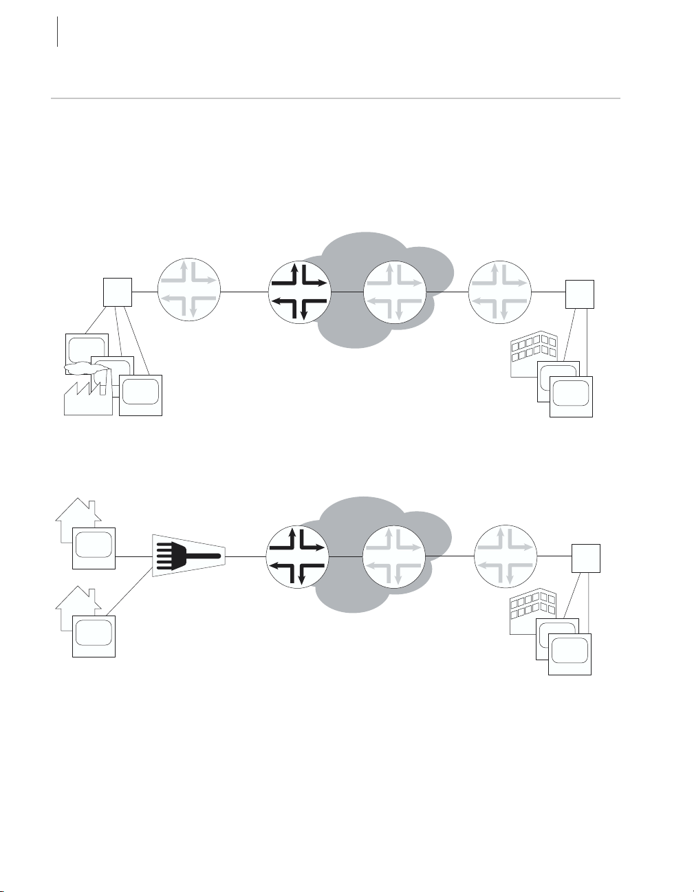
Communications with the router can take place over a variety of media.
Figure 1-1 and Figure 1-2 illustrate the location of E-series routers as an
edge router in an end-to-end Internet network. In Figure 1-1, the
customers are businesses using T1/T3 communication lines. In
Figure 1-2, the customers are using digital subscriber lines (DSLs) with a
DSL access multiplexer (DSLAM).
Internet
Hub
PC
Home office
PC
Home office
PC
Desktop
Remote
access
router
DSLAM
T1/T3
Figure 1-1 E-series router communicating over T1/T3 lines
DS3 OC3
ERX
ERX
OC3
Core
router
Internet
Core
router
Remote
access
router
Remote
access
router
Hub
PC
g013033
Desktop
Hub
PC
g013034
Desktop
Figure 1-2 E-series router communicating over DSL lines
Page 25
CPE
CPE
E-Series Routers
E-Series Routers
In Figure 1-3, the ERX-310 router is being used as an access router in a
small POP location. The router is deployed by the service provider at the
customer site as a CPE (customer premises equipment).
xDSL
T1/E1
T3/E3
GE
ERX
SONET or ATM
infrastructure
GE
OC3
VPN
1-3
CPE
E-Series Routers
GE
OC3/12
cOC3
cOC12
Figure 1-3 ERX-310 router deployed in a small POP
ISP
Five models of E-series routers are available:
• ERX-1440 router
• ERX-1410 router
• ERX-710 router
• ERX-705 router
• ERX-310 router
All models use the same software. However, the specific model
determines the:
• Combination of line modules supported
• Conditions for line rate performance of line modules
• Type, capacity, and number of SRP modules used
g013726
Page 26

CHAPTER 1
1-4
E-Series Overview
ERX-14xx Models
Note: In the E-series documentation, the term ERX-14xx models refers to both the
ERX-1440 router and the ERX-1410 router. The terms ERX-1440 router and
ERX-1410 router refer to the specific models. See Figure 1-4 and Figure 1-5.
The ERX-1440 router manages an extremely high volume of network
traffic, and uses a 40-Gbps switch route processor (SRP) module, either
the SRP-40G or SRP-40G+ module. (The SRP-40G+ module obsoletes
the SRP-40G module; however, the software continues to support both
modules.) In this model, all line modules operate at full wire speed
simultaneously.
The ERX-1410 router manages high levels of network traffic, and uses the
10-Gbps SRP module (SRP-10G). You can configure the ERX-1410
router to enable the line modules either to operate at full line rate
performance or to allow line modules to operate at a rate dependent on
the resources available. The former option restricts the allowed
combinations of line modules. For information on configuring
performance of line modules, see E-Series System Basics Configuration
Guide, Chapter 5, Managing Line Modules and SRP Modules.
Note: The 10-Gbps SRP module used in the ERX-310 router is different from the
10-Gbps SRP module used in the ERX-1410 router. See section SRP Module,
later in this chapter, for more information.
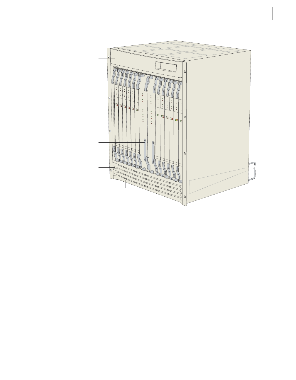
Externally, the ERX-1440 chassis is the same as the ERX-1410 chassis
(see Figure 1-4 and Figure 1-5). Both routers contain 14 vertical slots to
accommodate modules.
Internally, the ERX-1440 chassis differs from the ERX-1410 chassis, and
includes a special midplane for the 40-Gbps SRP module.
Installation procedures and operating procedures are identical for both
systems. All ERX-7xx/14xx models use the same SRP I/O module, but
different power input modules are used.
Note: The router may look different from the routers shown in the figures in this
chapter, depending on the line modules in the slots.
Page 27
Fan tray
behind bezel
Line module
SRP module
PCMCIA slot
Air filter (optional)
behind bezel
E-Series Routers
E-Series Routers
1-5
Bezel
Figure 1-4 ERX-14xx model, front view
g013727
Cable
management
bracket
Page 28
CHAPTER 1
1-6
E-Series Overview
Fan tray
I/O
module
SRP I/O
module
Power input
module
Cable
management
bracket
ERX-7xx Models
Plenum
g013727
Figure 1-5 ERX-14xx model, rear view
Note: In the E-series documentation, the term ERX-7xx models refers to both the
ERX-705 router and the ERX-710 router. The terms ERX-705 router and ERX-710
router refer to the specific models. See Figure 1-6 and Figure 1-7.
The ERX-7xx models are robust, high-density routers with less capacity
than the ERX-14xx models. The ERX-7xx models use either the
SRP-10G module or the SRP-5G module.
You can configure the ERX-7xx models to enable the line modules to
operate either at full line rate performance or at a rate dependent on the
resources available. For information about configuring performance of
line modules, see E-Series System Basics Configuration Guide,
Chapter 5, Managing Line Modules and SRP Modules.
Note: The 10-Gbps SRP module used in the ERX-310 router is different from the
10-Gbps SRP module used in the ERX-710 router. See section SRP Module, later
in this chapter, for more information.
Page 29
E-Series Routers
E-Series Routers
The ERX-705 chassis is the same as the ERX-710 chassis (see Figure 1-6
and Figure 1-7). The chassis contains seven slots to accommodate
modules. Installation procedures and operating procedures are identical
for both systems. All ERX-7xx/14xx models use the same SRP I/O
module, but different power input modules are used.
Note: The router may look different from the routers shown in the figures in this
chapter, depending on the line modules in the slots.
Line module
Fan tray
SRP module
1-7
PCMCIA slot
Figure 1-6 ERX-7xx model, front view
I/O
modules
Power input
module
Power switches
SRP I/O module
Figure 1-7 ERX-7xx model, rear view
g013729
g013730
Page 30
CHAPTER 1
1-8
E-Series Overview
ERX-310 Router
The ERX-310 router is a low-end platform that supports all of the same
services as the ERX-7xx/14xx models, but with smaller capacity and
scaling capabilities. Like the ERX-7xx/14xx models, the ERX-310 router
uses the same software architecture, providing a single IP entry point into
the network with the same IP-based protocols and services that are
available on other E-series routers. The ERX-310 router is designed to be
used as a small distributed POP router as well as a high-end CPE router.
The ERX-310 router is a three-slot chassis with a midplane architecture.
One slot supports one nonredundant 10-Gbps SRP module, while the
other two slots support line modules. The router supports existing E-series
ASIC-based line modules (except the OC48/STM16 line module).
Note: The 10-Gbps SRP module used in the ERX-310 router is different from the
10-Gbps SRP module used in the ERX-7xx/14xx models. See section SRP
Module, later in this chapter, for more information.
The ERX-310 router is available in either redundant AC- or DC-powered
models.
Fan tray
Line modules
PCMCIA slot
SRP module
AC power
supply A
Figure 1-8 ERX-310 router, front view (AC model)
Note: DC model has blank filler panels in power supply slots.
AC power
supply B
g013731
Page 31

g013732
AC power inputs and
switches A and B
Grounding posts
Figure 1-9 ERX-310 router, rear view (AC model)
E-Series Routers
E-Series Routers
I/O module
SRP I/O
module
ESD grounding jack
1-9
g013733
I/O
module
SRP I/O
module
ESD grounding jack
DC power inputs
and switches A and B
Grounding posts
Figure 1-10 ERX-310 router, rear view (DC model)
Page 32

CHAPTER 1
1-10
E-Series Overview
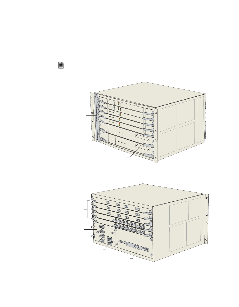
E-Series Modules
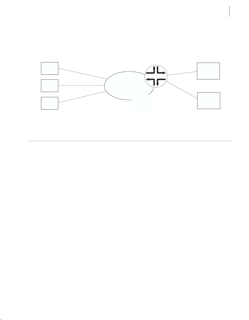
The system supports an SRP module and a selection of line modules. You
can use any line module for access or uplink. Access line modules receive
traffic from low-speed circuits, and the system routes the traffic onto
higher-speed uplink line modules and then to the core of the network.
Each module connects to a corresponding I/O module via a passive
midplane. See Figure 1-11.
The front panel of each module contains a collection of status LEDs
(light-emitting diodes). For information about how to interpret the LEDs,
see Chapter 10, Troubleshooting.
Line modules
SRP modules
Line modules
I/O modules
SRP I/O
module
I/O modules
Connection via
passive midplane
g013734
Figure 1-11 Modules in ERX-14xx model
Page 33

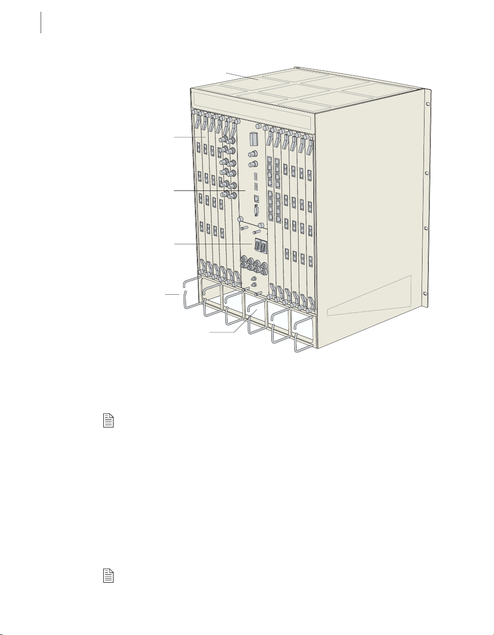
SRP Module
E-Series Modules
E-Series Routers
Switch route processor (SRP) modules perform system management,
routing table calculations and maintenance, forwarding table
computations, statistics processing, configuration storage, and other
control plane functions. Each SRP module is a PowerPC-based system
with its own memory, nonvolatile disk storage, and power supply (see
Figure 1-12 and Figure 1-13).
Fabric board
Ejector
Midplane
connectors
Status LEDs
1-11
Board reset
button
NMI button
PCMCIA
NVS card
Figure 1-12 ERX-7xx/14xx SRP module
System
processor board
g013735
Page 34

CHAPTER 1
1-12
E-Series Overview
g013736
Ejector
Midplane
connectors
Status
LEDs
PCMCIA
NVS card
Board reset
button
NMI button
Figure 1-13 ERX-310 SRP module
Integrated fabric system
processor board
Module Details
ERX-7xx/14xx models use up to two redundant SRP modules operating
in an active/standby conf iguration. ERX-310 routers use only one SRP
module. An SRP module must be present for any system to boot.
SRP modules ranging from 5 Gbps to 40 Gbps can be used in
ERX-7xx/14xx models. Only a 10-Gbps SRP module (SRP-SE10G) can
be used in ERX-310 routers. See Chapter 12, Module Specifications for
complete information.
Note: Because of different physical dimensions and switch fabric capabilities, SRP
modules are not interchangeable between systems. For example, the 10-Gbps
SRP module used in ERX-7xx/14xx models cannot be used in the ERX-310 router,
and vice versa.
Page 35

SRP I/O Module
E-Series Modules
E-Series Routers
Caution: Do not remove the SRP module while the system is running.
For details about installing SRP modules, see Chapter 5, Installing
Modules.
SRP Module Redundancy
SRP module redundancy is available only for ERX-7xx/14xx models. See
Redundancy Features, later in this chapter, for more information.
Nonvolatile Storage
The PCMCIA slot on the front of the SRP module holds a Type II
PCMCIA nonvolatile storage (NVS) card (see Figure 1-12 and
Figure 1-13). This card is loaded with the system’s software and
configuration files. The PCMCIA card is factory installed.
The SRP I/O module is a single corresponding input/output module that
interfaces with the SRP module(s) through the system’s midplane. The
same SRP I/O module works with all SRP modules, but is router specific.
The I/O module used in ERX-7xx/14x models cannot be used in the
ERX-310 router, and vice versa. See Figure 1-5, Figure 1-7, and
Figure 1-9 for locations.
1-13
Module Details
The SRP module provides standard craft management interfaces,
including:
• 10/100Base-T – Enables access to the E-series router for Ethernet
management functions via CLI or SNMP, for example.
• RS-232 – Provides a serial connection for monitoring the system’s
hardware configuration through a PC (running terminal emulation
software) or ASCII terminal. Allows direct CLI access.
• Alarm contacts – Provide for remote indication of critical, major, and
minor E-series router alarms (ERX-7xx/14xx models only; currently
not implemented)
• External timing inputs – Provide a method of ensuring that the clock
timing used by the E-series router remains synchronized with the
network’s system clock. BNC connectors and wire wraps are available
for ERX-7xx/14xx models only.
Page 36

CHAPTER 1
1-14
E-Series Overview
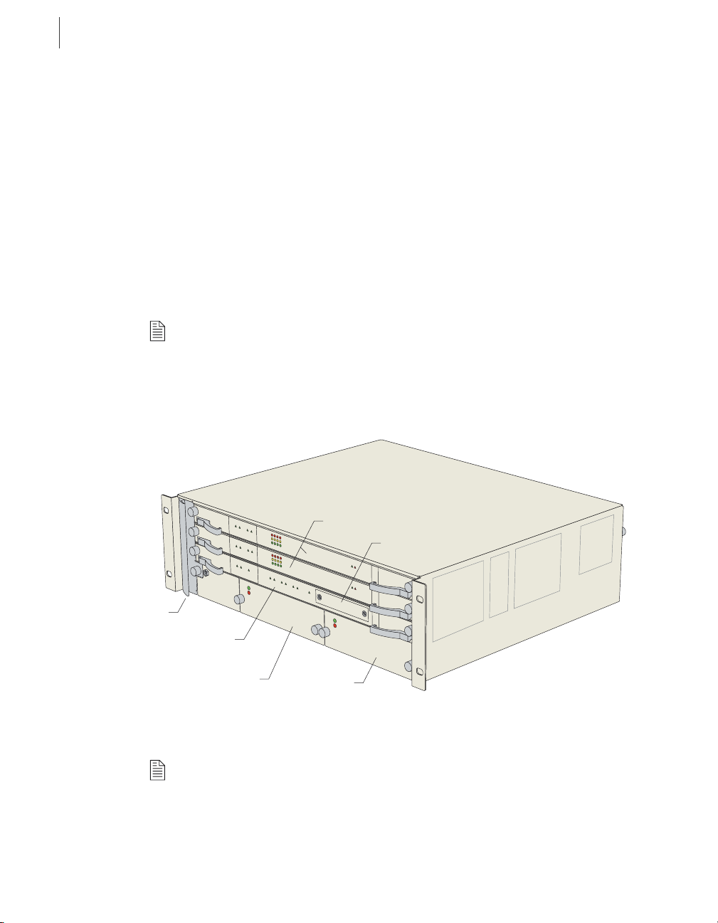
Line Modules
For details about installing the SRP I/O module, see Chapter 5, Installing
Modules.
Line modules process data from different types of network connections.
For information about available line modules and which SRP modules
support specific line modules, see Chapter 12, Module Specifications.
Figure 1-14 shows a representative line module. For details about
installing line modules, see Chapter 5, Installing Modules.
Ejector
Status LEDs
Board reset
button
NMI button
Figure 1-14 Representative line module
Midplane
connectors
g013737
Page 37

I/O Modules
Network Management Tools
E-Series Routers
Packet Classification
Most line modules support packet classification on ingress (some
non-ASIC line modules do not). A classification engine on the line
module matches specific f ields (such as source and destination IP address,
source and destination port, and protocol), the ingress IP interface, layer
2 fields, or some combination of these against user-configured filters at
wire speed.
Most line modules have a corresponding input/output (I/O) module that
provides the physical interconnection to the network. Insert each I/O
module into the back of the system, directly behind its corresponding line
module.
For information about which line modules pair with which I/O modules,
see Chapter 12, Module Specifications. See Figure 1-5, Figure 1-7, and
Figure 1-9 for locations. For details about installing I/O modules, see
Chapter 5, Installing Modules.
1-15
Network Management Tools
You can use different management tools to configure the system to meet
the specific networking requirements.
CLI Management
The CLI provides fully developed and automated configuration and
status functionality through a local RS-232 port, Telnet, or SSH via any
reachable network. For a full discussion of the CLI, see the E-Series
System Basics Configuration Guide, Chapter 2, Command Line
Interface.
SNMP MIB Management
The system offers a complete SNMP interface for configuration, status,
and alarm reporting. The system supports both Standard and Enterprise
MIBs (Management Information Bases). The Juniper Networks E-Series
Enterprise MIB is ASN.1 notated for easy importing into third-party
SNMP management applications. For more information, see E-Series
System Basics Configuration Guide, Chapter 3, Configuring SNMP.
Page 38

CHAPTER 1
1-16
E-Series Overview
NMC-RX Device Management System
The NMX-RX application provides a global method of managing all
routers, line modules, and ports through a graphical user interface.
Redundancy Features
The system has the following redundancy features:
SRP Modules
Note: This section applies to ERX-7xx/14xx models only. ERX-310 routers contain
one SRP module and therefore do not offer SRP module redundancy.
ERX-7xx/14xx models use a 1:1 redundancy scheme for the SRP module.
When two SRP modules of the same type are installed in the chassis, one
acts as a primary and the second as a standby. Both SRP modules share a
single SRP I/O module located in the rear of the chassis. If the primary
SRP fails, the redundant SRP module assumes control without rebooting
or initializing. (As a consequence, if you upgrade software, you must copy
the software to the redundant SRP and reboot it.) For information about
configuring and managing SRP module redundancy, see the E-Series
System Basics Configuration Guide, Chapter 5, Managing Line Modules
and SRP Modules.
After you install two SRP modules, the modules negotiate for the primary
role. A number of factors determine which module becomes the primary;
however, preference is given to the module in the lower-numbered slot.
The SRP modules record their latest roles and retain them the next time
you switch on the system. For information about installing SRP modules,
see Chapter 5, Installing Modules.
NVS Cards
If you have two SRP modules installed in a system, you can use NVS
cards of different capacities on the SRP modules. The effective capacity
of the higher-capacity NVS card will equal that of the lower-capacity
NVS card. For information about installing NVS cards, see Chapter 5,
Installing Modules.
When you install new NVS cards or SRP modules, you must issue the
synchronize command to match the file system of the NVS card on the
redundant SRP module with the file system of the NVS card on the
primary SRP module. (The NVS card on the redundant SRP module will
hereafter be referred to as the redundant NVS card; the NVS card on the
Page 39

Redundancy Features
E-Series Routers
primary SRP module will hereafter be referred to as the primary NVS
card.)
If the capacity of the primary NVS card is equal to or smaller than that of
the redundant NVS card, the system copies all the files from the primary
NVS card to the redundant NVS card. However, if the capacity of the
primary NVS card exceeds that of the redundant NVS card, the system
creates an invisible synchronization reserve file on the primary NVS
card, provided that there is enough space for the f ile.
The purpose of the synchronization file is to prevent the creation of data
that will not fit on the redundant NVS card. The file contains no useful
data, and is not visible when you view the files in NVS. The size of the file
is equal to the difference in capacities of the two NVS cards. For example,
if the primary NVS card has a capacity of 224 MB and the redundant
NVS card has a capacity of 220 MB, the size of the synchronization file is
4 MB, and only 220 MB of space is available on the primary NVS card.
If there is not enough space on the primary NVS card to create the
synchronization reserve file, the synchronize command fails, and a
warning message is displayed on the console. To resolve this issue, either
delete unwanted files from the primary NVS card or replace the
redundant NVS card with a higher-capacity NVS card.
1-17
Line Modules
Note: This section applies to ERX-7xx/14xx models only. ERX-310 routers do not
offer line module redundancy.
ERX-7xx/14xx models support line module redundancy for several line
modules. For details about which line modules support redundancy, see
Chapter 12, Module Specifications. In this scheme, an extra line module
in a group of identical line modules provides redundancy in case of line
module failure. To use this feature, you need a:
• Spare line module
• Redundancy midplane
• Redundancy I/O module
A redundancy midplane may cover 3–6 slots. It provides additional
connectivity that enables the spare line module to assume control of the
I/O module associated with any failed line module in the redundancy
group. The spare I/O module provides connectivity from the spare line
module to the redundancy midplane.
Page 40

CHAPTER 1
1-18
E-Series Overview
The process by which the system switches to the spare line module is
called switchover. When switchover occurs, the system:
1 Breaks the connection between the primary I/O module and the
primary line module.
2 Connects the primary I/O module to the spare line module via the
redundancy midplane and redundancy I/O module.
Protocol processing then takes place on the spare line module.
Figure 1-15 shows the data f low when a spare line module becomes
active.
Redundancy
I/O module
Primary
I/O module
g013738
Spare line module
Primary line module
Figure 1-15 Data flow when a spare line module is active
Midplane
Redundancy
midplane
1. A packet arrives at the primary I/O module.
2. The packet passes along the redundancy
midplane from the primary I/O module to
the redundancy I/O module.
3. The packet passes from the redundancy
I/O module to the spare line module.
4. The spare line module processes the packet.
Page 41

Power
Fans
Redundancy Features
E-Series Routers
For information about installing modules for line module redundancy, see
Chapter 5, Installing Modules. For information about configuring and
managing SRP module redundancy, see E-Series System Basics
Configuration Guide, Chapter 5, Managing Line Modules and SRP
Modules.
All E-series routers provide a power architecture that distributes
redundant –48 VDC feeds through the router to each line module, SRP
module, and fan module where DC-to-DC converters provide local
conversion to the required secondary voltages.
The ERX-310 router is available with either DC or AC power inputs. The
AC-powered version can be configured with one or two hot-swappable
power supplies for optional redundancy (see Figure 1-8 and Figure 1-9).
The power supplies convert AC power to internal –48 V redundant DC
feeds that are then distributed through the router.
Forced air-cooling keeps the temperature of the E-series modules and
components within normal operating limits. In ERX-14xx models, six
cooling fans are located in a tray at the top of the router (see Figure 1-4).
In ERX-7xx models, four cooling fans are located in a tray on one side of
the router (see Figure 1-6). In the ERX-310 router, two cooling fans are
located in a tray on one side of the router (see Figure 1-8).
1-19
The system monitors the temperature of each module. If the temperature
of a module exceeds the maximum limit, the system immediately goes
into thermal protection mode. In this mode, the modules consume
extremely low levels of power. For information about troubleshooting
high operating temperatures, see Chapter 10, Troubleshooting.
In ERX-7xx/14xx models, the fan tray has two redundant converters that
power the fans (for the ERX-14xx models, a –24 V, 50 W converter; for
the ERX-7xx models, a –12 V, 15 W converter). If one converter fails, the
other takes over. The ERX-310 router does not have redundant
converters.
For all E-series routers, the system software reports an alarm if any of the
fans or converters fail.
Page 42

CHAPTER 1
1-20
E-Series Overview
Page 43

Unpacking and Inspecting E-Series Routers
This chapter reviews shipping contents and unpacking procedures for
E-series routers.
Top ic Page
Before You Begin 2-1
Unpacking ERX-14xx Models 2-2
Unpacking ERX-7xx Models and ERX-310 Routers 2-3
Inspecting E-Series Router Components and Accessories 2-3
If You Detect or Suspect Damage 2-3
Contacting Juniper Networks 2-3
The Next Step 2-4
2
Before You Begin
Before you begin unpacking the router, be sure you have the following
tools:
• A No. 2 Phillips screwdriver
• A utility knife
• A mechanical lift, or at least two people to assist in lifting
Page 44

CHAPTER 2
2-2
Unpacking and Inspecting E-Series Routers
Unpacking ERX-14xx Models
ERX-14xx models come boxed, bolted, and strapped to a skid. For your
convenience, Juniper Networks recommends that you unpack the E-series
router in the location where you want to install it.
Heavy-Equipment Warning: Three people are required to install the E-series
router in a rack: two to lift the system into position and one to screw it to the rack.
To unpack ERX-14xx models:
1 Cut the two straps that secure the carton to the skid, open the carton
from the top, and remove the box of accessories that sits on top of the
router.
2 Unlock the four plastic clips that hold the box to the skid by
squeezing them in their center and pulling out, and then lift the
carton off the router.
3 Remove the three screws that attach each of the two L-brackets to
the router.
4 To avoid scratching the router when removing it from the skid,
detach one of the L-brackets from the skid by removing the three
screws. See Figure 2-1.
Figure 2-1 Removing an L-bracket
L-bracket
g013739
Page 45

Unpacking ERX-7xx Models and ERX-310 Routers
E-Series Routers
Unpacking ERX-7xx Models and ERX-310 Routers
ERX-7xx models and ERX-310 routers are shipped boxed, but not
attached to a skid. For your convenience, Juniper Networks recommends
that you unpack the E-series router in the location where you want to
install it.
To unpack an ERX-7xx model or an ERX-310 router:
1 Open the carton from the top.
2 Remove the box of accessories that sits on top of the system.
3 Remove the router from the box.
Heavy-Equipment Warning: Three people are required to install the E-series
router in a rack: two to lift the system into position and one to screw it to the rack.
Inspecting E-Series Router Components and Accessories
After you remove the equipment from the shipping containers:
• Confirm the contents of each container.
2-3
• Inspect all external surfaces and external connectors for visible signs of
damage.
• Inspect all accessories shipped with each unit.
• Document any damage noted during your inspection.
• Confirm that the router has the correct number and type of modules
for your ordered configuration.
If You Detect or Suspect Damage
If you detect or suspect damage to any equipment:
• Contact the shipper responsible for delivery, and formally report the
damage.
• Contact your Juniper Networks sales representative or reseller.
Contacting Juniper Networks
Please contact Juniper Networks at 1-888-314-JTAC (within the United
States) or 408-745-9500 (from outside the United States), or contact your
sales representative if you have any questions or concerns. See
Appendix C, Customer Support, for complete contact information.
Page 46

CHAPTER 2
2-4
Unpacking and Inspecting E-Series Routers
The Next Step
• To familiarize yourself with the electrical, environmental, and other
• If you are familiar with these guidelines and requirements, turn to
guidelines and requirements for installing E-series routers, turn to
Chapter 3, Installation Guidelines and Requirements.
Chapter 4, Installing E-Series Routers.
Page 47

Installation Guidelines and Requirements
This chapter reviews preinstallation considerations such as electrical,
environmental, and safety compliances for E-series routers. For complete
system specifications, refer to Chapter 11, System Specifications.
Top ic Page
Your Preinstallation Responsibilities 3-1
Environmental Requirements 3-2
Regulatory Compliances 3-2
Safety Guidelines 3-3
Equipment Rack Requirements 3-4
Cabling Recommendations 3-8
3
Your Preinstallation Responsibilities
Complete the following tasks before installing the system:
• Verify that the electrical supply meets all AC and DC power
requirements. See Chapter 11, System Specifications.
• Verify that the site meets all environment specifications. See
Environmental Requirements later in this chapter and Chapter 11,
System Specifications.
• Verify that the cables you plan to use meet the specifications, and
review the cabling recommendations. See Cabling Recommendations
later in this chapter.
• Verify the operation of all telephone circuits, digital services, and T1
facilities required for installation.
Page 48

CHAPTER 3
3-2
Installation Guidelines and Requirements
• Ensure that all IP environment requirements are met, such as
autonomous system (AS) number, port IP address and mask,
management Ethernet port IP address and mask, and broadcast
address.
Environmental Requirements
Refer to Chapter 11, System Specifications for complete environmental
specifications.
Choose a location for the router that is dry, relatively dust free, well
ventilated, and air conditioned. If you install equipment in a rack, be sure
that the floor is capable of supporting the combined weight of the rack
and the installed equipment. Place the router in a location with sufficient
access to power and network cables.
Like other network devices, the router generates a significant amount of
heat. It is important to provide a balanced environment so that the router
performs properly and safely. See Chapter 11, System Specifications for
acceptable ranges of temperature and humidity.
Be sure to allow enough space around the router for adequate ventilation.
Inadequate ventilation can cause the system to overheat.
Caution: Do not block the air vents on E-series routers. Otherwise, the router may
overheat.
Regulatory Compliances
Refer to Chapter 11, System Specifications, for a complete list of
regulatory compliance requirements, including safety, EMC, and
telecommunications.
Page 49

Safety Guidelines
For your safety, before installing t he system, review all safety warnings in
this section.
Temperature Warning: The recommended maximum ambient temperature is
50° C (122° F). The internal temperature of the rack should be considered for safe
operation.
Rack Installation Warning: Install equipment in the rack from the bottom upward.
This will maintain the stability of the rack and reduce the chance of the rack’s
tipping over.
Heavy-Equipment Warning: Two people are required to lift an E-series router.
Three people are required to install an E-series router in a rack. The equipment is
extremely heavy.
Ground (Earth) Warning: Connect the E-series router or rack to ground (earth),
and ensure that a reliable grounding path is maintained in the rack.
Lightning Activity Warning: Do not work on the system or connect or disconnect
cables during lightning activity.
DC Power Disconnection Warning: Before powering on the E-series router,
remove power from the DC circuit by deactivating the circuit breaker on the panel
board that services the DC circuit.
Safety Guidelines
E-Series Routers
3-3
Power Connection Warning: Before servicing the E-series router, turn off the
power.
Jewelry Removal Warning: Remove jewelry (including rings, necklaces, and
watches) before working on equipment that is connected to power lines. Metal
objects heat up when connected to power and ground and can cause serious
burns or become welded to the terminals.
Metal Objects Warning: Do not insert any metal object, such as a screwdriver,
into an open slot or the backplane. Doing so may cause electric shock and serious
burns.
Branch Circuit Caution: Evaluate the overall loading of the branch circuit before
you install any equipment into a rack.
Page 50

CHAPTER 3
3-4
Installation Guidelines and Requirements
ERX-310 Power Cord Warnings (AC Model)
This unit has more than one power-supply cord. Disconnect 2 power cords
BEFORE servicing to avoid electric shock.
Denne enhed har mere end een strømfordelingsledning. Fjern ledning(er) nummer 2
FØR eftersyn for at undgå elektrisk stød.
Waarschuwing! Dit apparaat heeft meerdere netsnoeren. Vermijd elektrische schok!
Verwijder 2 netsnoeren ALVORENS onderhoud te verrichten.
Tässä laitteessa on useampi kuin yksi verkkojohto. Irrottakaa 2 verkkojohtoa ENNEN
huoltoa sähköiskujen välttämiseksi.
Attention: Cet appareil comporte plus d'un cordon d'alimentation. Afin de prévenir les
chocs électriques, débrancher les 2 (donner le nombre de cordons) cordons
d'alimentation AVANT le dépannage.
Dieses Gerät hat mehrere Stromversorgungskabel. Klemmen Sie 2 Stromkabel VOR
der Wartung ab, um einen elektrischen Schlag zu vermeiden.
L'unità ha più di un cavo di alimentazione. Scollegare 2 cavi di alimentazione PRIMA di
usarla, onde evitare scosse elettriche.
Denne enheten har mer enn en nett-tilkobling. 2 nettkabler må frakobles FØR service
for å unngå elektrisk støt.
Este equipamento tem mais do que um cabo de alimentação. Para que se evitem
choques, desligar 2 cabos, ANTES de servir o equipamento.
Esta unidad tiene más de un cable de toma de corriente. Desconecte 2 cables ANTES
de darle mantenimiento a la unidad, para evitar descargas eléctricas.
Denna enhet har fler än en nätanslutningskabel. Koppla bort 2 nätanslutingskablar
INNAN du påbörjar service.
Equipment Rack Requirements
When allocating equipment rack space, consider the following:
• Type of equipment racks recommended for E-series routers
• Number of equipment racks required to hold your current E-series
router configuration
• Future expansion
Your distribution rack should meet basic mechanical and space
requirements and comply with conventional standards. In the United
States, use EIA-310-D Cabinets, Racks, Panels, and Associated
Equipment, September 1992.
Page 51

ERX-310 router
ERX-7xx model
Plenum
Equipment Rack Requirements
E-Series Routers
3-5
ERX-14xx model
Figure 3-1 E-series routers installed in a rack
g013740
Page 52

CHAPTER 3
3-6
Installation Guidelines and Requirements
Mechanical Requirements
Follow these mechanical requirements for your rack:
• Select from the following rack options:
• The rack must have at least two mounting posts.
• The distance between the mounting holes in the two posts must be
• Do not use an enclosed rack for ERX-7xx models or the ERX-310
• A fully loaded rack with three ERX-14xx models must structurally
• Optional mounting kits are available for 19-inch and 23-inch rack
> Two-post rack – a freestanding enclosed cabinet with two
mounting posts in the front
> Telco-type rack – two adjacent mounting posts that you must
secure to the floor or an overhead structure
> Four-post rack – a freestanding open rack, either open or closed
18.31 inches ±.063 inch, as specified in the EIA-310-D.
router. It does not provide adequate ventilation.
support 300 pounds (136 kilograms).
mounting (mid- and front-chassis mounting). Contact your Juniper
Networks sales representative for more information.
Space Requirements
If you use an enclosed rack for an ERX-14xx model, ensure that there is a
minimum of 3 inches of clearance between the inner side wall and the
router. This clearance space will allow adequate air flow.
Proper Rack Installation
To confirm proper equipment rack installation, check the following:
• Racks are installed and electrically grounded according to
manufacturer instructions.
• Equipment racks are anchored to the floor and, when possible,
anchored to the ceiling as well.
• Equipment rack installations comply with applicable local, state, and
national codes.
Warning: To maintain airflow requirements, a plenum must be installed above
ERX-14xx models before any other piece of equipment is installed above the
router.
Page 53

Equipment Rack Requirements
E-Series Routers
3-7
ERX-310 router and
Air output
ERX-7xx model
Air intake
ERX-14xx model
Air intake ERX-310 router
and ERX-7xx model
Air output ERX-14xx model
via plenum
3- to 4-ft.
(0.9- to 1.2-m)
access space
7-ft. (2.1-m) rack
g013741
Figure 3-2 Airflow for E-series routers
Page 54

CHAPTER 3
3-8
Installation Guidelines and Requirements
Cabling Recommendations
You may want to consult the document GR-63 (LSSGR, FD-15): Network
Equipment Building System (NEBS) Requirements: Physical Protection,
Issue 1, October 1995 for additional cable recommendations.
Comply with the following recommendations:
• Use only shielded cables.
• Ensure that cable distance and rate limits meet IEEE-recommended
maximum speeds and distances for signaling purposes. For
information about attenuation and power loss in optical fiber cables
see:
> ANSI T1.646a-1997 Telecommunications – Broadband ISDN -
Physical Layer Specification for User-Network Interfaces Including
DS1/ATM (1997)
> ANSI T1.646-1995 Telecommunications – Broadband ISDN -
Physical Layer Specification for User-Network Interfaces Including
DS1/ATM (1995)
> AT&T (Lucent) Technical Note Power Margin Analysis (November
1995)
• Ensure that power cables deliver sufficient power to the system.
• Attach laser fiber connectors only to Class 1 laser devices in
accordance with IEC 825-1, Safety of Laser Products - Part 1.
• Route cables so that they do not restrict ventilation or airf low.
• Route cables so that modules and field-replaceable units are easily
accessible.
• Route cables in a logical direction to prevent loss of connectivity to
other equipment in the rack, associated equipment in adjacent racks,
or to the backbone network.
• Consider using cable-management brackets to keep network cables
untangled and orderly and to prevent cables from hindering access to
other slots.
• For specifications on cables for line modules, see Chapter 12, Module
Specifications.
Page 55

Installing E-Series Routers
This chapter describes how to install E-series routers in a rack.
Top ic Page
Before You Begin 4-1
Freestanding Installation 4-2
Rack-Mounted Installation 4-3
The Next Step 4-6
Before You Begin
Before installing E-series routers, be sure you:
• Have a plan for installing E-series routers. This plan should consider
future expansion of your system.
4
• Have the tools and accessories needed to complete the installation.
• Read and understand the clearance requirements for the front and
back of the chassis for cable routing and other unit access. See
Environmental Requirements on page 3-2 for more information.
• Prepare the equipment racks by measuring and marking space for
each E-series router and plenum you will install.
Page 56

CHAPTER 4
4-2
Installing E-Series Routers
Freestanding Installation
When installing the system on a table top or in any other freestanding
mode, be sure to leave enough space around the system for adequate
ventilation. Position the router with easy access to the connections that it
needs for power, local communications, and remote communications.
See Chapter 3, Installation Guidelines and Requirements, and
Chapter 11, System Specifications, for more information.
Warning: Two people are required to lift an E-series router.
Note: All persons handling an E-series router should wear an antistatic device.
Connectors are located on the I/O modules and the power input module
and are installed from the rear of the router (see Figure 4-1). See
Chapter 6, Cabling E-Series Routers, for cabling installation procedures.
I/O
modules
Power input
module
Power switches
SRP I/O module
Figure 4-1 ERX-7xx model, rear view
g013730
Page 57

Rack-Mounted Installation
Juniper Networks recommends that you use a standard EIA distribution
rack. Refer to Equipment Rack Requirements in Chapter 3, Installation
Guidelines and Requirements, for detailed rack information.
Installation Guidelines
Before installing the systems in a rack, consider the following guidelines
and refer to Figure 4-2:
• You c a n in s ta l l up to t h ree ERX-14 xx models, six ERX-7xx models, or
fourteen ERX-310 routers in a single 7-ft. (2.1 m) rack.
Installing multiple systems in a single rack allows you to maximize
your available space.
• You can install an ERX-14xx model, an ERX-7xx model, and an
ERX-310 router together in the same rack (see Figure 4-2).
If you install an ERX-7xx model or ERX-310 router directly above an
ERX-14xx model in the same rack, you must install a plenum between
the ERX-7xx model or ERX-310 router and the ERX-14xx model so
that the air can circulate between the systems (see Figure 3-2). This
plenum is available from Juniper Networks.
Rack-Mounted Installation
E-Series Routers
4-3
If you install an ERX-14xx model above an ERX-7xx model or
ERX-310 router, there is no need to install a plenum between the units
because the ERX-7xx models and ERX-310 routers vent air out the
side of the chassis.
Warning: To maintain airflow requirements, a plenum must be installed above
an ERX-14xx model before any other piece of equipment is installed above the
router.
• Install heavier systems, such as an ERX-14xx model, on the bottom of
the rack. Lighter systems, such as the ERX-310 router, should be
mounted higher in the rack.
Page 58

CHAPTER 4
4-4
Installing E-Series Routers
ERX-310 router
ERX-7xx model
Plenum
ERX-14xx model
Figure 4-2 E-series routers installed in recommended order
g013740
Page 59

Safety Guidelines
Rack-Mounted Installation
E-Series Routers
Observe the following safety guidelines when mounting the router in a
rack.
Rack Installation Warning: Install equipment in the rack from the bottom upward.
This will maintain the stability of the rack and reduce the chance of the rack’s
tipping over.
Heavy-Equipment Warning: Three people are required to install the E-series
router in a rack: two to lift the system into position and one to screw it to the rack.
Branch Circuit Warning: Evaluate the overall loading of the branch circuit before
you install any equipment into a rack.
Ground (Earth) Warning: Connect the E-series router or rack to ground (earth),
and ensure that a reliable grounding path is maintained in the rack.
Lightning Activity Warning: Do not work on the system or connect or disconnect
cables during lightning activity.
DC Power Disconnection Warning: Before powering on the E-series router,
remove power from the DC circuit by deactivating the circuit breaker on the panel
board that services the DC circuit.
4-5
Servicing Unit Warning: Before servicing the E-series router, turn off the power.
Jewelry Removal Warning: Remove jewelry (including rings, necklaces, and
watches) before working on equipment that is connected to power lines. Metal
objects heat up when connected to power and ground and can cause serious
burns or become welded to the terminals.
Metal Objects Warning: Do not insert any metal object, such as a screwdriver,
into an open slot or the backplane. Doing so may cause electric shock and serious
burns.
ERX-310 Router Power Cord Warning: The ERX-310 router AC model has more
than one power-supply cord. Disconnect 2 power cords BEFORE servicing to
avoid electric shock.
Preparing the Equipment Racks
Following your installation plan, use a tape measure and marking pen to
measure and mark space on each equipment rack for each E-series router
component. Horizontal spacing should follow NEBS requirements. If you
choose not to install a plenum, be sure to include 2 U of space between
the each chassis to allow for proper exhaust. A plenum, however, is highly
recommended.
Page 60

CHAPTER 4
4-6
Installing E-Series Routers
Installing the Router
To complete the installation of the router in a rack, you need:
• A Phillips screwdriver
• Depending on the router, up to eight 10-32 x 3/8 Phillips screws
(provided with the router ) for each router to be installed
Warning: Three people are required to install the E-series router in a rack: two to
lift the system into position and one to screw it to the rack.
Note: All persons handling an E-series router should wear an antistatic device.
To install the router in the rack:
1 Position the router in its designated location in the equipment rack.
Make sure the holes of the mounting brackets align evenly with the
holes of the equipment rack on both sides.
Note: One person should stand on the left side of the router, and another should
stand on the right side when lifting.
2 Starting at the bottom, secure the router in the equipment rack by
using the 10-32 x 3/8 Phillips screws.
The Next Step
3 Connect the necessary cables (see Chapter 6, Cabling E-Series
Routers, for instructions on installing the cables).
Figure 4-2 illustrates a distribution rack with one ERX-310 router, one
ERX-7xx model, and one ERX-14xx model installed.
After you finish installing the router:
• If you need to install any modules, turn to Chapter 5, Installing
Modules.
• If the router was delivered with the modules already installed, turn to
Chapter 6, Cabling E-Series Routers, for instructions on connecting
cables.
Page 61

Installing Modules
This chapter describes how to install and remove E-series modules.
For information about managing installed modules, see E-Series System
Basics Configuration Guide, Chapter 5, Managing Line Modules and
SRP Modules.
Top ic Page
Overview 5-1
Safety Guidelines 5-7
Installing SRP I/O and SRP Modules 5-7
Installing Line and I/O Modules 5-10
Removing a Module 5-11
Installing Components for Line Module Redundancy 5-13
Configuring Line Module Redundancy 5-16
The Next Step 5-16
5
Overview
Line module slots are located in the front of each E-series chassis, while
I/O module slots are located in the rear. See Chapter 1, E-Series
Overview, for front and rear views of E-series routers.
In ERX-14xx models, modules mount vertically in a chassis with 14 slots.
In ERX-7xx models and ERX-310 routers, modules mount horizontally
in a chassis with 7 slots and 3 slots, respectively. See Figure 5-1.
Page 62

CHAPTER 5
5-2
Installing Modules
ERX-7xx model
ERX-14xx model
Slot Groups
g013742
ERX-310 router
Figure 5-1 Orientation of line modules in E-series routers
For details about available line modules, see Chapter 12, Module
Specifications. For information about compatibility between lines
modules and SRP modules, see Tab le 12-2 in Chapter 12, Module
Specifications.
The slots in the ERX-1410 router and the ERX-7xx models are divided
into groups. The number of groups and number of slots per group
depend on the system.
There are no slot groups in the ERX-1440 router or the ERX-310 router.
In the ERX-310 router, slot 0 contains the SRP module and slots 1 and 2
contain a line module.
Page 63

Overview
E-Series Routers
Slot Groups for the ERX-1410 Router
A slot group in the ERX-1410 router comprises three adjacent chassis
slots. The groups for the ERX-1410 router consist of the following slots
(Figure 5-2):
• Slot group 1 – slots 0 through 2
• Slot group 2 – slots 3 through 5
• Slot group 3 – slots 8 through 10
• Slot group 4 – slots 11 through 13
Slots 6 and 7 are reserved for the SRP modules.
Chassis slots
12340 5 6 7 8 9 10 11 12 13
5-3
SRP SRP
CT3 OC3CT1 OC3CT1CT1 CT3 CT3 CT3
Slot
group 1
Figure 5-2 ERX-1410 slot groups
Slot
group 2
Slot
group 3
Slot
group 4
g013743
Page 64

CHAPTER 5
5-4
Installing Modules
Slot Groups for the ERX-7xx Models
A slot group in an ERX-7xx model comprises one slot or two adjacent
slots. The groups for an ERX-7xx model consist of the following slots
(Figure 5-3):
• Slot group 1 – slots 2 and 3
• Slot group 2 – slot 4
• Slot group 3 – slot 5
• Slot group 4 – slot 6
Slots 0 and 1 are reserved for the SRP modules.
.
6
5
4
3
2
Chassis slots
1
OC3CE1 CE1
E3 ATM
Slot group 4
Slot group 3
Slot group 2
Slot group 1
0
Figure 5-3 ERX-7xx model slot groups
Combinations of Line Modules
For information about allowed combinations of line modules, see E-Series
System Basics Configuration Guide, Chapter 5, Managing Line Modules
and SRP Modules.
OC48 Line Modules
The ERX-1440 router with the SRP-40G+ SRP module supports OC48
line modules. Other E-series routers do not support OC48 line modules.
An OC48 line module spans two slots in an ERX-1440 router. You can
install this line module only in slots 2–3 and slots 4–5. Other slots in the
system do not support this line module.
The corresponding OC48 Frame APS I/O module spans only one slot.
Install the I/O module in the lower of the slots (either slot 2 or slot 4) that
the line module spans.
SRP SRP
g013744
Page 65

Replacing and Managing Modules Using the Software
For information about software procedures associated with replacing and
managing modules, see E-Series System Basics Configuration Guide,
Chapter 5, Managing Line Modules and SRP Modules.
Hot-Swapping Modules
All E-series routers support hot-swapping of modules. Hot-swapping
allows you to add or remove a module without powering down the
system.
Protecting Modules and Slots
Each E-series chassis has an ESD (electrostatic discharge) grounding jack.
See Table 5 -1 for locations. To prevent damage from electrostatic
discharge, connect an antistatic wrist strap to the jack when handling
components.
Overview
E-Series Routers
5-5
Antistatic
ESD grounding jack
Figure 5-4 Connecting the wrist strap to the ERX-310 router (rear)
Tabl e 5 - 1 Grounding jack locations
E-Series Router Location
ERX-14xx model Front: inside front bezel in lower-left corner
Rear: upper-right corner
ERX-7xx model Rear: lower-right corner
ERX-310 router Front: lower-left corner
Rear: lower-right corner
wrist strap
g013745
Page 66

CHAPTER 5
5-6
Installing Modules
Order of Installation
To protect the modules and slots when installing modules, observe the
following guidelines:
Caution: When handling modules, use an antistatic wrist strap connected to the
E-series router’s ESD grounding jack. This action helps to protect the module from
damage by electrostatic discharge.
Caution: Always handle the module by its edges. Do not touch the components,
pins, leads, or solder connections.
Caution: If you meet strong resistance when attempting to seat the module using
the ejectors, remove it from the chassis and confirm that the slot is one designed to
hold the module. Also, be sure that you have aligned the top and bottom edges in
the correct matching tracks.
Caution: Be sure to cover every empty slot with a blank faceplate to protect the
system from dust or other foreign substances and to ensure proper system cooling.
Caution: Do not discard the antistatic bag. When a module is not in use, store it in
an antistatic bag.
Before you attempt to install or replace a module (inserted in the front of
the chassis), the corresponding I/O module (inserted in the rear of the
chassis) should already be in place. The system diagnostics run when a
module is installed in a chassis slot. If the corresponding I/O module is
not present, the diagnostics fail, and you need to remove and reinsert the
module.
Required Tools and Safety Items
You need the following tools to install a line module:
• A Phillips screwdriver
• An ESD wrist strap
Page 67

Safety Guidelines
Before and during the installation process, observe the following
precautions:
Lightning Activity Warning: Do not work on the system or connect or disconnect
cables during lightning activity.
DC Power Disconnection Warning: Before powering on the E-series router,
remove power from the DC circuit by deactivating the circuit breaker on the panel
board that services the DC circuit.
Jewelry Removal Warning: Remove jewelry (including rings, necklaces, and
watches) before working on equipment that is connected to power lines. Metal
objects heat up when connected to power and ground and can cause serious
burns or become welded to the terminals.
Metal Objects Warning: Do not insert any metal object, such as a screwdriver,
into an open slot or the backplane. Doing so may cause electric shock and serious
burns.
Repair Warning: Never attempt to repair parts of modules yourself. Only trained
customer service personnel are authorized to service parts. Call Juniper Networks
Customer Service to make arrangements to return defective modules for repair.
Safety Guidelines
E-Series Routers
5-7
Installing SRP I/O and SRP Modules
SRP modules should be installed in specific slots in each router. See
Table 5-2 for SRP module slot assignments.
Tabl e 5 - 2 SRP module slot assignments
E-Series Router Slot
ERX-14xx model 6 and 7
ERX-7xx model 0 and 1
ERX-310 router 0
Note: Because of different physical dimensions and switch fabric capabilities, SRP
modules are not interchangeable between systems. For example, the 10-Gbps
SRP module used in ERX-7xx/14xx models cannot be used in an ERX-310 router,
and vice versa.
Note: Install the SRP I/O module before you install the SRP module; otherwise, the
system diagnostics will fail.
Page 68

CHAPTER 5
5-8
Installing Modules
Installing an SRP I/O Module
To install an SRP I/O module:
1 Ground yourself by using an antistatic wrist strap or other device.
2 With a Phillips screwdriver, loosen the captive screws that secure the
blank faceplate covering the empty chassis slot, if present, and
remove the faceplate.
3 Remove the SRP I/O module from its antistatic bag.
4 Slide the module into the chassis by placing it between the guides of
the selected slot and pushing the module until it stops.
Note: See figures in Chapter 1, E-Series Overview, for module locations.
5 Tighten the module’s captive screws using a Phillips screwdriver.
Turn both screws several times before tightening them completely to
allow the module to sit correctly.
Installing an SRP Module
To install an SRP module:
1 Ground yourself by using an antistatic wrist strap or other device.
Note: See figures in Chapter 1, E-Series Overview, for module locations.
2 Choose the slot in which you want to install the module.
• ERX-14xx models – slot 6 or 7
• ERX-7xx models – slot 0 or 1
• ERX-310 router – slot 0
3 With a Phillips screwdriver, loosen the captive screws that secure the
blank faceplate covering the empty chassis slot, if present, and
remove the faceplate.
4 Remove the SRP module from its antistatic bag.
5 Verify that the ejectors are in the open position, as shown in
Figure 5-5.
Page 69

Opened
Closed
Closed
Installing SRP I/O and SRP Modules
E-Series Routers
5-9
Opened
g013746
Figure 5-5 Ejectors in the open position
6 Slide the module into the chassis by placing it between the guides of
the selected slot and pushing the module until it stops.
The module stops sliding when the ejectors make contact with the
front of the chassis.
Caution: If you meet strong resistance when attempting to seat the module using
the ejectors, remove it from the chassis and confirm that the slot is one designed to
hold the module. Also, be sure that you have aligned the top and bottom edges in
the correct matching tracks.
7 Insert the module into the backplane by simultaneously depressing
both ejectors (as shown in Figure 5-5) and exerting forward pressure
on the module.
Page 70

CHAPTER 5
5-10
Installing Modules
8 Tighten the module’s captive screws using a Phillips screwdriver.
Alternately turn each screw several times before tightening them
completely to allow the module to sit correctly.
Installing Line and I/O Modules
This section describes the procedures for installing line and I/O modules.
Note: Install the I/O module before you install the corresponding line module;
otherwise, the system diagnostics fail, and after the line module has tried to reboot,
its status will be “inactive” when you issue the show version command.
Installing a Line Module or an I/O Module
To install a module:
1 Ground yourself by using an antistatic wrist strap or other device.
2 Choose the slot where you want to insert the module.
Note: Line modules are in the front of the system, and I/O modules are in the back
of the system.
Tabl e 5 - 3 Module slot assignments
E-Series Router Module Slot
ERX-1440 router • Install modules other than the OC48 modules in slots 0–5 and
slots 8–13
• Install the OC48 line module in slots 2–3 and slots 4–5
› Install the corresponding I/O module only in the lower of
the two slots (either slot 2 or slot 4) that the line module
spans
ERX-1410 router Install modules in slots 0–5 and slots 8–13
ERX-7xx model Install modules in slots 2–6
ERX-310 router Install modules in slots 1–2
3 With a Phillips screwdriver, loosen the screws that secure the blank
faceplate covering the empty chassis slot, if present, and remove the
faceplate.
4 Remove the module from its antistatic bag.
5 Verify that the ejectors are in the open position, as shown in
Figure 5-5.
6 Guide the module into the chassis by placing it between the guides of
the selected slot and pushing the module until it stops.
Page 71

Caution: If you meet strong resistance when attempting to seat the module using
the ejectors, remove it from the chassis and confirm that the slot is one designed to
hold the module. Also, be sure that you have aligned the top and bottom edges in
the correct matching tracks.
7 Insert the module into the midplane by simultaneously depressing
8 Tighten the module’s captive screws using a Phillips screwdriver.
Removing a Module
Note: Although not required, it is recommended that you issue the slot disable
command from the CLI before removing a module.
Caution: If you do not use the halt command before removing or powering down
an SRP, the system’s NVS card may become corrupted.
Removing a Module
E-Series Routers
The module stops sliding when the ejectors make contact with the
front of the chassis.
both ejectors (as shown in Figure 5-5) and exerting forward pressure
on the module.
Alternately turn each screw several times before tightening them
completely to allow the module to sit correctly.
5-11
To remove a module:
1 Enter the halt command.
See E-Series System Basics Configuration Guide, Chapter 5,
Managing Line Modules and SRP Modules for information about
the halt command.
2 Ground yourself by using an antistatic wrist strap or other device.
3 Use a screwdriver to loosen the thumb screws located at the top and
bottom of the module panel.
4 Pull the ejector handles located at the top and bottom of the module
so that they are in position 2, as shown in Figure 5-6.
Page 72

CHAPTER 5
5-12
Installing Modules
Opened
Closed
Closed
Opened
Figure 5-6 Ejectors in the closed position
5 Carefully slide the module out of the chassis.
6 Place the module in its antistatic bag.
7 Cover the empty chassis slot with a blank faceplate, and tighten the
g013747
faceplate’s captive screws using a Phillips screwdriver. Turn both
screws several times before tightening them completely.
If you remove an I/O module and not the corresponding line module, the
line module reboots. Its status becomes “inactive” when you issue the
show version command.
If you remove a line module and do not delete the corresponding
configuration, the status of the line module will be “not present” when
you issue the show version command.
Page 73

Installing Components for Line Module Redundancy
Installing Components for Line Module Redundancy
A spare line module provides redundancy for a group of identical line
modules for ERX-7xx/14xx models only.
Note: The ERX-310 router does not support line module redundancy.
For line module redundancy to operate, you must install:
• The line modules, including the spare line module
• The redundancy midplane
• The I/O modules, including the spare I/O module
For more information, see Redundancy Features in Chapter 1, E-Series
Overview.
Warning: Do not insert any metal object, such as a screwdriver, or place your hand
into an open slot or the backplane when the E-series router is on. Remove jewelry
(including rings, necklaces, and watches) before working on equipment that is
connected to power lines. These actions prevent electric shock and serious burns.
Caution: When handling modules, use an antistatic wrist strap connected to the
E-series router’s ESD grounding jack, and hold modules by their edges. Do not
touch the components, pins, leads, or solder connections. These actions help to
protect modules from damage by electrostatic discharge.
5-13
E-Series Routers
Installing the Line Modules
To install the line modules in a redundancy group:
1 Install the spare line module in the lowest-numbered slot of the
redundancy group.
2 Install the other line modules in the remaining slots. (See Installing
Line and I/O Modules earlier in this chapter).
Installing the Redundancy Midplane
To install the redundancy midplane in a redundancy group:
Caution: If you do not use the halt command before removing or powering down
an SRP, the system’s NVS card may become corrupted.
1 Enter the halt command.
See E-Series System Basics Configuration Guide, Chapter 5,
Managing Line Modules and SRP Modules for information about
the halt command.
Page 74

CHAPTER 5
5-14
Installing Modules
Warning: Turn off the E-series router before you install the redundancy midplane.
Working inside the router when it is on can lead to electric shock and serious
burns.
2 Turn off the power switches located on the power input module in
the rear of the system (see Figure 5-7).
3 Remove the I/O modules from the slots that the redundancy
midplane will span.
4 Place the redundancy midplane in the chassis so that it rests against
the guides below the chassis midplane (see Figure 5-7).
5 Align the screw holes in the redundancy midplane with the screw
holes in the guides so that the midplane covers the slots for the
redundancy group.
6 Using a Phillips screwdriver and the screws provided, loosely attach,
but do not tighten, the redundancy midplane to the guides.
7 Carefully insert an I/O module in one slot to ensure that the
redundancy midplane is aligned correctly; then tighten the screws.
Caution: A misaligned redundancy midplane can result in bent pins on the
backplane and midplane and poor contact between the I/O modules and the
redundancy midplane.
Page 75

Installing Components for Line Module Redundancy
E-Series Routers
5-15
Redundancy
midplane
Figure 5-7 Installing a redundancy midplane
Installing the I/O Modules
To install the I/O modules in a redundancy group:
1 Install the redundancy I/O module in the lowest-numbered slot of
the redundancy group.
Caution: When setting up a redundancy group with line modules, be sure to install
the redundancy I/O module in the lowest-numbered slot of the redundancy group.
It is possible to install the redundancy I/O module in other slots; however, doing so
may damage other I/O modules connected to the redundancy midplane.
2 Install the corresponding I/O module for the line module of each slot
in the redundancy group. (See Installing a Line Module or an I/O
Module, earlier in this chapter.)
3 Cable each module to provide a path to the remote interface (see
Chapter 6, Cabling E-Series Routers).
g013748
Page 76

CHAPTER 5
5-16
Installing Modules
Verifying the Installation
To verify that the installation is complete:
1 After you have cabled the system for power (see Chapter 6, Cabling
E-Series Routers), turn on the power switches.
The system reboots.
2 Issue the show redundancy command, and verify that the display
shows the redundancy hardware.
Configuring Line Module Redundancy
For information about configuring line module redundancy, refer to
E-Series System Basics Configuration Guide, Chapter 5, Managing Line
Modules and SRP Modules.
The Next Step
After you install the modules, you can connect cables to the system. Turn
to Chapter 6, Cabling E-Series Routers.
Page 77

Cabling E-Series Routers
This chapter describes how to cable an E-series router. Before you cable
the router, ensure that you have completed all installation instructions
identified in previous chapters.
Top ic Page
Cabling Overview 6-1
Required Tools, Wires, and Cables 6-4
Cabling the SRP I/O Module 6-5
Cabling the E-Series Router for Power 6-9
Cabling I/O Modules 6-14
The Next Step 6-20
6
Cabling Overview
Cabling an E-series router requires the following main tasks:
1 Familiarize yourself with the module ports, and ensure that you have
2 Read and understand all safety warnings. (See Chapter 3,
3 (Optional) Connect timing ports.
4 Connect the SRP I/O module to the network and to a management
5 Connect grounding wires to the E-series chassis.
the cables and wires needed to complete each cabling procedure (see
Figure 6-1).
Installation Guidelines and Requirements.)
console.
Page 78

CHAPTER 6
6-2
Cabling E-Series Routers
6 Connect the power cables from the power source to the power input
module.
7 Connect the line I/O modules to their appropriate network interface.
Note: Juniper Networks recommends that you use shielded cables where
appropriate.
Page 79

Cabling Overview
E-Series Routers
6-3
OC3-4
I/O module
(slot 12)
I/O module
(slot 9)
Port 0
CT3
RX
TX
Alarm leads
External timing ports (Europe)
External timing ports (North America)
OC3
OC3-4
I/O
I/O
SINGLE
MODE
OC3-4
I/O
SINGLE
MODE
CT3
CT3
I/O
SRP I/O module
(slot positions 6 and 7)
FE-8 I/O module
(slot 5)
I/O
ALARMSEXTERNAL TIMINGCONSOLE
MINOR
MAJOR
CRITICAL
E1 75 OHM
CLOCK IN
+
-
+
-
+
-
FE-8
I/O
Port 0
Port 1
Port 2
ATG
T1 100 OHM
CLOCK IN
10/100
BASE T
RS-232
BTG
R
R
Port 3
10/100 BASE T port
RS-232 terminal port
OC3
I/O module
(slot 13)
Port 1
Blank
faceplate
Ejector
RX
TX
THIS PRODUCT IS EQUIPPED WITH
TWO POWER FEEDS. DISCONNECT
BOTH FEEDS PRIOR TO SERVICE.
POWER A POWER B
-48VDC -48VDCRTN RTN
POWER A POWER B
OFF
|
|
ON
ON
O
O
OFF
Power input module
Power A and Power B
on/off switches
Power A and Power B
input connectors
-48VDC RTN -48VDC RTN
Ground terminals
WARNING!
NO OPERATOR ACCESSIBLE
COMPONENTS. AUTHORIZED
!
SERVICE PERSONNEL ONLY.
Figure 6-1 E-series ports and connectors (ERX-14xx model shown)
g013749
Page 80

CHAPTER 6
6-4
Cabling E-Series Routers
Required Tools, Wires, and Cables
Cabling your system should take only a few minutes. You will need the
items listed below and in Table 6-1 for proper installation.
• 1/8" flathead screwdriver
• 3/8" wrench or 3/8" nut-driver
• No. 2 Phillips screwdriver
• Ground wires – We recommend a minimum of 10-AWG ground wire.
• #10 (ERX-7xx/14xx models) or #8 (ERX-310 router) kep nut to
connect the ground (earth) wire to the ground terminal.
• Power input module wiring – We recommend a minimum of 10-AWG
(ERX-7xx/14xx model) or 14-AWG (ERX-310 router DC model) wire
with a dual stud terminal lug with 3/8" spacing. For the ERX-310
router AC model, use a standard IEC power cord.
Tabl e 6 - 1 Required cables
Connection Port and Cable Used
Management connection between SRP
I/O module and the LAN
Management connection between SRP
I/O module and a management console
Direct connections to I/O modules See Table 12-3 in Chapter 12, Module
One 10/100Base-T Ethernet management
port with an RJ-45 connector
One RS-232 port with a DB-9 connector for
VT100 management access
Specifications for specific I/O module
connector information
Note: If you plan on using a cable-management bracket (ERX-7xx/14xx models
only), install it before you begin cabling your E-series router. Cable-management
brackets are helpful to keep network interface cables untangled and orderly and to
prevent cables from hindering access to other slots. See Installing a
Cable-Management Bracket on ERX-7xx Models in Chapter 9, Maintaining
E-Series Routers.
Page 81

Cabling the SRP I/O Module
Before powering up the E-series router, you must set up a management
console. The console enables you to communicate with your system
during the power-up process and to manage your system using the
command line interface (CLI).
When connecting a console directly to the SRP I/O module, use a cable
appropriate for your terminal connector. The cable must have a female
DB-9 connector to attach to the RS-232 port on the SRP I/O module.
See Figure 6-2 and Figure 6-3.
The console port is considered a data terminal equipment interface
(DTE). Direct connection to a terminal or PC (which also have DTE
interfaces) requires a crossover cable.
Note: The alarm function on the SRP I/O module is currently not implemented.
Only ERX-7xx/14xx models have external timing ports and alarm leads
located on the SRP I/O module. All E-series routers have console ports
located on the SRP I/O module. See Table 6 -2 for details on each
component.
Cabling the SRP I/O Module
E-Series Routers
6-5
Tab l e 6 - 2 SRP I/O ports
Port Description
Alarm leads
(ERX-7xx/14xx
models only)
External timing ports
(ERX-7xx/14xx
models only)
Console ports • One 10/100Base-T Ethernet management port with an RJ-45 connector
Six terminal blocks for external alarm contacts; use a minimum 26-AWG for each (currently
not implemented)
• Two 3-pin wire-wrap posts for US external clock sources; primary (A) and secondary (B)
• Two BNC connectors for E1 clock sources; primary (A) and secondary (B)
• One RS-232 port with a DB-9 connector for VT100 management access
External Timing Ports
Note: This section applies to ERX-7xx/14xx models only. The ERX-310 router
does not support external timing.
There are two input ports on the SRP I/O module for external clock
sources. These ports provide a way to ensure that the E-series router
system clock remains synchronized with the network’s system clock. The
primary clock is labeled A; the secondary, redundant clock is labeled B.
Use the connectors appropriate for your locale (European or North
American standard):
Page 82

CHAPTER 6
6-6
Cabling E-Series Routers
• European – Two 75-ohm E1 2.048-Mbps inputs with BNC connectors
• North American – Two 100-ohm T1 inputs with three pin wire-wrap
Note: Use shielded cables to connect the external clock sources to the clock
source input ports.
BNC (Europe)
connectors. Pins are labeled T (tip), G (ground), and R (ring). We
recommend using 26-AWG wire minimum.
+
26-AWG wire
ALARMSEXTERNAL TIMING
MINOR
MAJOR
CRITICAL
E1 75 OHM
CLOCK IN
-
+
-
+
-
RJ-45
DB-9
Wire-wrap connectors
(North America, Japan)
CONSOLE
Figure 6-2 ERX-14xx model SRP I/O module
T1 100 OHM
CLOCK IN
10/100
BASE T
RS-232
T
A
G
R
T
B
G
R
g013750
Page 83

Console Ports
Cabling the SRP I/O Module
E-Series Routers
To connect the clock source input ports:
1 Depending on the connector type, complete one of the following
tasks:
• E1: Attach the BNC connector to Clock A’s external timing port.
• T1: Wrap the tip wire on pin marked T of Clock A’s external
timing port, the ground wire on G pin, and the ring wire on R
pin.
Note: You can use a wire-wrap gun to attach wires to pins.
2 Attach the opposite end of the external timing cable or wires to your
network’s clock source A.
3 Repeat steps 1 and 2 for the Clock B connections.
Note: This section applies to all E-series routers.
6-7
There are two ports located in the Console section of the SRP I/O
module (see Figure 6-2 and Figure 6-3) that allow management access.
• The 10/100Base-T Ethernet port accepts an RJ-45 (male)
connector, providing an out-of-band connection for LAN access
through a Telnet session or SNMP.
• The RS-232 port accepts a DB-9 (female) connector, allowing
direct CLI access from a console terminal.
The console port is considered a data terminal equipment
interface (DTE). Direct connection to a terminal or PC (which
also have DTE interfaces) requires a crossover cable.
Page 84

CHAPTER 6
6-8
Cabling E-Series Routers
SRP I/O module
RS-232 10/100
BASE T
Figure 6-3 ERX-310 router SRP I/O module
g013751
See Chapter 8, Accessing E-Series Routers, for more information about
management access.
Connecting to the Network
To connect the E-series router to the network:
1 Insert an Ethernet cable (RJ-45) connector into the 10/100Base-T
(RJ-45) port on the SRP I/O module until it clicks into place.
2 Connect the other end of the cable to the appropriate Ethernet
network for an out-of-band connection.
Connecting to a Console Terminal
When you connect a console directly to the E-series router SRP I/O
module, use a cable appropriate for your terminal connector. The cable
must have a female DB-9 connector to attach to the RS-232 port on the
SRP I/O module.
To connect the console to the SRP I/O module:
1 Insert the female DB-9 connector into the RS-232 port, and tighten
the screws.
2 Connect the other end of the cable to your terminal’s serial port
(VT100/ANSI).
Page 85

Cabling the E-Series Router for Power
After you have correctly cabled the modules and I/O modules, you must
attach grounding and electrical wires before you attempt system
power-up. There are three main tasks involved:
1 Switch all E-series router power switches to OFF.
Caution: Switches may have inadvertently flipped to ON during shipping and
installation.
2 Connect the grounding wires to the chassis.
Warning: Always connect the grounding wires first (before connecting the power
cables) and disconnect them last when installing or servicing the E-series router.
3 Connect the power cables (AC or DC) to the power input modules.
See Chapter 11, System Specifications for the power requirements for the
E-series router. Table 6 -3 identifies the power input module cabling
requirements, and Figure 6-4 shows the main components of a power
input module.
Cabling the E-Series Router for Power
E-Series Routers
6-9
Tabl e 6 - 3 Power input module cables/wires needed
Cable/Wire From To
ERX-7xx/14xx models
One 10-AWG
ground wire
Two 10-AWG wire
leads
Two 10-AWG wire
leads
ERX-310 router
One 10-AWG
ground wire
Two 14-AWG wire
a
leads
Two 14-AWG wire
a
leads
One AC power
b
cord
a. DC model only
b. AC model only
Power input module ground
terminal
Power input module Power A
–48 VDC and RTN leads
Power input module Power B
–48 VDC and RTN leads
Power input module ground
terminal
Power input module Power A
–48 VDC and RTN leads
Power input module Power B
–48 VDC and RTN leads
Power input module AC power
IEC receptacle
Termination ground
Appropriate leads on power
source No. 1
Appropriate leads on power
source No. 2
Termination ground
Appropriate leads on power
source No. 1
Appropriate leads on power
source No. 2
Appropriate AC power supply
Page 86

CHAPTER 6
|
ON
O
OFF
|
ON
O
OFF
WITH
POWER A POWER
POWER B
-48VDCTN RTN
|
ON
O
OFF
|
ON
O
OFF
POWER A POWER B
POWER B
-48VDC RTN
-48VDC RTN
O
OFF
PO
-48VDC
-48VDC
6-10
Cabling E-Series Routers
THIS PRODUCT IS EQUIPPED WITH
TWO POWER FEEDS. DISCONNECT
BOTH FEEDS PRIOR TO SERVICE.
POWER A POWER B
Power A
leads
|
ON
O
OFF
POWER A POWER B
-48VDC -48VDCRTN RTN
-48VDC RTN -48VDC RTN
WARNING!
NO OPERATOR ACCESSIBLE
!
COMPONENTS. AUTHORIZED
SERVICE PERSONNEL ONLY.
ON
O
OFF
|
Power B
leads
Ground
Figure 6-4 ERX-14xx model, power input module
Power input
module cover
g013752
Task 1: Turn Off All E-Series Router Power
Before starting, you must switch all E-series router power switches to
OFF.
• To turn off the router, push each power switch to the OFF position.
Page 87

Task 2: Connect the Grounding Cables
All E-series routers have two grounding studs located in the rear of the
chassis, near the power inputs. Each stud provides grounding for a single
power unit.
To ground each power unit:
1 Locate the grounding studs on the E-series router (see Figure 6-4 and
Figure 6-5).
2 Remove the nuts and locking washers from the grounding studs.
Note: We recommend a minimum of 10-AWG ground wire with a ring style
terminal.
3 Place the grounding cable lead on one of the grounding studs and
tighten the nuts to secure the connection.
4 Connect the other end of the ground cable to the appropriate
ground termination lead.
5 Repeat steps 3–4 for the remaining grounding stud.
Cabling the E-Series Router for Power
E-Series Routers
6-11
Note: When grounding an E-series router, leave a service loop in the grounding
cable to ensure that the grounding cable is the last cable to disconnect from the
shelf if strain is placed on the electrical cables.
Task 3: Connect the Power Cables
To connect power cables to an E-series router, follow these steps. Refer to
Figure 6-4, Figure 6-5, and Figure 6-6 as needed.
ERX-7xx models, ERX-14xx models, ERX-310 router (DC model)
Caution: Before you begin this procedure, ensure that all power switches are in
the OFF position.
1 Be sure you have completed Task 1 and Task 2 in the previous
sections.
2 If applicable, loosen the screws from the clear power input module
cover and remove it.
Warning: Be sure the power source is turned off, the E-series router is turned off,
and proper grounding wires are attached before continuing with this procedure.
Page 88

CHAPTER 6
6-12
Cabling E-Series Routers
Warning: The wiring color code of the power cables depends on the color coding
of the DC power source installed at your site. Color code standards for DC wiring
do not exist. To ensure that the correct polarity is connected to the E-series router
power units, confirm the connection of the power cables to the + (positive) and
– (negative) leads at the power source.
3 Remove the nuts and locking washers from the posts for the power
input (A or B) using a small insulated adjustable wrench.
4 Place one negative (neutral) cable lead on the post labeled –48 VDC.
5 Replace the locking washers and nuts, and tighten the nuts to secure
the connection.
6 Place the other cable lead on the post labeled RTN.
7 Replace the locking washer and nut, and tighten the nut to secure
the connection.
8 Attach the opposite end of Power A’s wire leads to the appropriate
leads on your power source.
Note: To provide redundancy, Power A and Power B leads should not terminate at
the same power source.
9 Place the clear plastic guard over the terminal posts, and secure it in
place by tightening the four screws.
10 Repeat steps 1–9 for each power input module in your configuration.
Power A
leads
DC power
Ground
input A
-48VDC RTN
OFF
O
Power A
POWER A
ON
|
switch
Figure 6-5 ERX-310 router, rear view (DC model)
DC power
input B
-48VDC RTN
OFF
O
Power B
switch
POWER B
ON
|
g013753
Page 89

Cabling the E-Series Router for Power
E-Series Routers
ERX-310 router (AC model)
1 Insert the power cord into the AC power IEC receptacle (see
Figure 6-6).
2 Insert the other end of the power cord into an appropriate AC power
source.
Note: To provide redundancy, Power A and Power B leads should not terminate at
the same power source.
3 Repeat steps 1–2 for the other power input module, if needed.
100-240V ~ 5A
O
|
POWER A POWER B
50/60 Hz
O
|
6-13
AC power input A
with switch
Ground
Figure 6-6 ERX-310 router, rear view (AC model)
AC power input B
with switch
g013754
Page 90

CHAPTER 6
6-14
Cabling E-Series Routers
Cabling I/O Modules
BNC Connectors
The following section illustrates the common connector types used with
E-series I/O modules. For information about the connectors on the
different line modules, see Chapter 12, Module Specifications.
.
CT3
I/O
RX
TX
TX
Figure 6-7 I/O module with BNCs
RX
Port 0
Port 1
g013755
Page 91

HSSI Connectors
Cabling I/O Modules
E-Series Routers
The HSSI I/O module uses a standard 50-pin HSSI connector.
Caution: Do not terminate HSSI connections with SCSI connectors. Although
SCSI connectors look very similar to HSSI connectors, using SCSI connectors on
HSSI connections may lead to data loss.
HSSI-3
I/O
6-15
Port 0
Figure 6-8 HSSI I/O module with 50-pin HSSI connector
g013756
Page 92

CHAPTER 6
6-16
Cabling E-Series Routers
RJ-45 Connectors
RJ-48C Connectors
When inserting an RJ-45 connector, be sure it clicks into the port.
10/100
FE-2
I/O
Port 0
g013757
Figure 6-9 I/O module with RJ-45 connector
When inserting an RJ-48C connector, be sure it clicks into the port.
Figure 6-10 I/O module with RJ-48C connectors
CE1
I/O
Port 0
g013758
Page 93

LC Duplex Connectors
In accordance with EN60825-1, Safety of Laser Products - Part 1:
Equipment Class, Requirements, and User’s Guide (2001), multimode
I/O modules with LC connectors are defined as follows:
CLASS 1 LED PRODUCT.
In accordance with EN60825-1, Safety of Laser Products - Part 1:
Equipment Class, Requirements, and User’s Guide (2001), single-mode
I/O modules with LC connectors are defined as follows:
CLASS 1 LASER PRODUCT.
Warning: Do not look directly into LC-style fiber connectors. The fiber-optic laser
used in single-mode fiber (SMF) meets the regulatory requirements for casual
exposure to the eye; however, looking directly into a laser can cause eye damage.
Warning: IEC 825, Class 1 laser fiber connectors are for connection only to Class
1 laser devices.
Cabling I/O Modules
E-Series Routers
6-17
OC3
I/O
TX
RX
RX
Figure 6-11 I/O module with LC full duplex connectors
TX
Port 0
Port 1
g013759
Page 94

CHAPTER 6
6-18
Cabling E-Series Routers
SC Duplex Connectors
In accordance with EN60825-1, Safety of Laser Products - Part 1:
Equipment Class, Requirements, and User’s Guide (2001), multimode
I/O modules with SC connectors are defined as follows:
CLASS 1 LED PRODUCT.
In accordance with EN60825-1, Safety of Laser Products - Part 1:
Equipment Class, Requirements, and User’s Guide (2001), single-mode
I/O modules with SC connectors are defined as follows:
CLASS 1 LASER PRODUCT.
Warning: Do not look directly into SC-style fiber connectors. The fiber-optic laser
used in single-mode fiber (SMF) meets the regulatory requirements for casual
exposure to the eye; however, looking directly into a laser can cause eye damage.
Warning: IEC 825, Class 1 laser fiber connectors are for connection only to Class
1 laser devices.
SC duplex connectors have the same basic shape as LC duplex
connectors, but are slightly larger. See Figure 6-11.
SMB Connectors
To cable I/O modules with SMB connectors, pull back the metal sheath
on the connector, insert the connector into the selected port, and release
the metal sheath.
CT3/T3
12
I/O
Port 0
g013760
Figure 6-12 I/O module with SMB connectors
Page 95

Cabling X.21/V.35 Connectors
Four cables are available for the X.21/V.35 I/O modules:
• X.21 DCE cable (terminated with 8 female X.21 connectors)
• X.21 DTE cable (terminated with 8 male X.21 connectors)
• V.35 DCE cable (terminated with 8 female V.35 connectors)
• V.35 DTE cable (terminated with 8 male V.35 connectors)
Each 200-pin proprietary socket on the I/O module provides connections
to 8 V.35 or X.21 ports. The remote end of the cable is terminated with
either 8 X.21 connectors or 8 V.35 connectors. The cable you attach to
the port on the I/O module determines whether the connection is X.21 or
V.35 and DCE or DTE.
X.21/V.35
I/O
Cabling I/O Modules
E-Series Routers
6-19
Port 0
Figure 6-13 X.21/V.35 module with 50-pin X.21/V.35 connector
g013761
Page 96

CHAPTER 6
6-20
Cabling E-Series Routers
Redundant Ports
The Next Step
Some modules have redundant ports. See Chapter 12, Module
Specifications for specifications. Cabling both ports provides a redundant
path to the E-series module.
Caution: For port redundancy to operate correctly on a GE I/O module that
supports SFPs, both the primary and redundant ports on an E-series GE I/O
module must use the same type of SFP.
Tur n to Chapter 7, Powering Up E-Series Routers.
Page 97

Powering Up E-Series Routers
This chapter describes how to power up an E-series router and determine
if it has booted properly.
Top ic Page
Before You Power Up the System 7-1
Powering Up 7-2
Status LEDs 7-3
Powering Down 7-3
The Next Step 7-3
Before You Power Up the System
7
Before powering up the system, you should complete the tasks shown in
Table 7-1. Refer to the appropriate chapters in this guide for information
about these tasks.
Warning: Be sure the power source is turned off and the system is turned off
before you perform the installation tasks.
Tabl e 7 - 1 Installation tasks
Installation Task Page
Install an SRP module and SRP I/O module 5-7
Install line modules and their corresponding I/O modules. 5-10
Cable all SRP I/O modules. 6-5
Connect a management console to the system. 6-7
(Optional) Connect the 10/100Base-T port to the network. 6-7
Page 98

CHAPTER 7
7-2
Powering Up E-Series Routers
Powering Up
Tabl e 7 - 1 Installation tasks (continued)
Installation Task Page
Warning: Be sure the power source is turned off and the system is turned off
before performing the following task.
Connect DC power or AC power to your E-series router.
(depending on model)
Cable all line modules. 6-14
Note: This procedure assumes that the system is already connected to a power
source. See Chapter 6, Cabling the E-Series Router for Power.
6-9
For specifications on the electrical requirements for the system, see
Chapter 11, System Specifications. For details on the power consumed by
the different E-series modules, see Chapter 12, Module Specifications.
Branch Circuit Caution: Evaluate the overall loading of the branch circuit before
you install any equipment into a rack.
To p owe r u p t h e sy s t e m :
1 Verify that the power source is operational and turned on.
2 Inspect all grounding and power connections to the E-series chassis.
3 Confirm that all connections are secure.
4 Switch the power switches to ON.
5 Monitor the LEDs on the front of the SRP modules to verify that the
system is booting properly. See Tabl e 10-2 in Chapter 10,
Tro u b le s hooting. for LED status explanations.
When the prompt appears on the system console, the system is in
User Exec mode and is ready to be configured:
host1>
6 Enter the enable command to access Privileged Exec mode:
host1>enable
host1#
In Privileged Exec mode you can begin to configure the system. See
the E-Series System Basics Configuration Guide, Chapter 2,
Command Line Interface for more information.
Page 99

Initialization Sequence
Each E-series line module is initialized independently. As a result, the
CLI on the SRP module may become available before the line modules
have completed initialization. Commands relating to a line module may
fail if the module has not completed initialization. The show version
command can be used to display line module status. Do not enter
commands for a line module until its state is “online”.
Status LEDs
Upon initial powerup, the components of the E-series router run boot
code, go through a series of self diagnostic tests, and synchronize with
each other.
When the tests are complete, use the LEDs on each module to determine
the status of the router. Observe the line module and SRP module LEDs
in the front, and the I/O line module and SRP I/O module LEDs in the
rear.
Refer to Chapter 10, Troubleshooting, for information on the system’s
LEDs.
Status LEDs
E-Series Routers
7-3
Powering Down
The Next Step
If you need to power down or remove the SRP module, first enter the
halt command to temporarily suspend the system’s operation. See
E-Series System Basics Configuration Guide, Chapter 4, Managing the
System for more information.
Caution: If you do not use the halt command before removing or powering down
an SRP module, the system’s NVS card may become corrupted.
If you shut down the system improperly, it will run an investigation of the
file allocation table (FAT) the next time it reboots.
If you have problems powering up the system, turn to Chapter 10,
Troubleshooting, for help.
If the system boots properly, turn to Chapter 8, Accessing E-Series
Routers.
Page 100

CHAPTER 7
7-4
Powering Up E-Series Routers
 Loading...