

Page 1

E Series™ Broadband Services Routers
ERX™ Hardware Guide
Release 11.1.x
Juniper Networks, Inc.
1194 North Mathilda Avenue
Sunnyvale, California 94089
USA
408-745-2000
www.juniper.net
Published: 2010-03-23
Page 2

Juniper Networks, the Juniper Networks logo, JUNOS, NetScreen, ScreenOS, and Steel-Belted Radius are registered trademarks of Juniper Networks, Inc. in
the United States and other countries. JUNOSe is a trademark of Juniper Networks, Inc. All other trademarks, service marks, registered trademarks, or
registered service marks are the property of their respective owners.
Juniper Networks assumes no responsibility for any inaccuracies in this document. Juniper Networks reserves the right to change, modify, transfer, or
otherwise revise this publication without notice.
Products made or sold by Juniper Networks or components thereof might be covered by one or more of the following patents that are owned by or licensed
to Juniper Networks: U.S. Patent Nos. 5,473,599, 5,905,725, 5,909,440, 6,192,051, 6,333,650, 6,359,479, 6,406,312, 6,429,706, 6,459,579, 6,493,347,
6,538,518, 6,538,899, 6,552,918, 6,567,902, 6,578,186, and 6,590,785.
E Series™ Broadband Services Routers ERX™ Hardware Guide, Release 11.1.x
Copyright © 2010, Juniper Networks, Inc.
All rights reserved. Printed in USA.
Writing: John Borelli, Helen Shaw, Krupa Chandrashekar
Editing: Ben Mann
Illustration: John Borelli
Cover Design: Edmonds Design
Revision History
April 2010—FRS JUNOSe 11.1.x
The information in this document is current as of the date listed in the revision history.
SOFTWARE LICENSE
The terms and conditions for using this software are described in the software license contained in the acknowledgment to your purchase order or, to the
extent applicable, to any reseller agreement or end-user purchase agreement executed between you and Juniper Networks. By using this software, you
indicate that you understand and agree to be bound by those terms and conditions.
Generally speaking, the software license restricts the manner in which you are permitted to use the software and may contain prohibitions against certain
uses. The software license may state conditions under which the license is automatically terminated. You should consult the license for further details.
For complete product documentation, please see the Juniper Networks Web site at www.juniper.net/techpubs.
ii ■
Page 3

END USER LICENSE AGREEMENT
READ THIS END USER LICENSE AGREEMENT (“AGREEMENT”) BEFORE DOWNLOADING, INSTALLING, OR USING THE SOFTWARE. BY DOWNLOADING,
INSTALLING, OR USING THE SOFTWARE OR OTHERWISE EXPRESSING YOUR AGREEMENT TO THE TERMS CONTAINED HEREIN, YOU (AS CUSTOMER
OR IF YOU ARE NOT THE CUSTOMER, AS A REPRESENTATIVE/AGENT AUTHORIZED TO BIND THE CUSTOMER) CONSENT TO BE BOUND BY THIS
AGREEMENT. IF YOU DO NOT OR CANNOT AGREE TO THE TERMS CONTAINED HEREIN, THEN (A) DO NOT DOWNLOAD, INSTALL, OR USE THE SOFTWARE,
AND (B) YOU MAY CONTACT JUNIPER NETWORKS REGARDING LICENSE TERMS.
1. The Parties. The parties to this Agreement are (i) Juniper Networks, Inc. (if the Customer’s principal office is located in the Americas) or Juniper Networks
(Cayman) Limited (if the Customer’s principal office is located outside the Americas) (such applicable entity being referred to herein as “Juniper”), and (ii)
the person or organization that originally purchased from Juniper or an authorized Juniper reseller the applicable license(s) for use of the Software (“Customer”)
(collectively, the “Parties”).
2. The Software. In this Agreement, “Software” means the program modules and features of the Juniper or Juniper-supplied software, for which Customer
has paid the applicable license or support fees to Juniper or an authorized Juniper reseller, or which was embedded by Juniper in equipment which Customer
purchased from Juniper or an authorized Juniper reseller. “Software” also includes updates, upgrades and new releases of such software. “Embedded
Software” means Software which Juniper has embedded in or loaded onto the Juniper equipment and any updates, upgrades, additions or replacements
which are subsequently embedded in or loaded onto the equipment.
3. License Grant. Subject to payment of the applicable fees and the limitations and restrictions set forth herein, Juniper grants to Customer a non-exclusive
and non-transferable license, without right to sublicense, to use the Software, in executable form only, subject to the following use restrictions:
a. Customer shall use Embedded Software solely as embedded in, and for execution on, Juniper equipment originally purchased by Customer from Juniper
or an authorized Juniper reseller.
b. Customer shall use the Software on a single hardware chassis having a single processing unit, or as many chassis or processing units for which Customer
has paid the applicable license fees; provided, however, with respect to the Steel-Belted Radius or Odyssey Access Client software only, Customer shall use
such Software on a single computer containing a single physical random access memory space and containing any number of processors. Use of the
Steel-Belted Radius or IMS AAA software on multiple computers or virtual machines (e.g., Solaris zones) requires multiple licenses, regardless of whether
such computers or virtualizations are physically contained on a single chassis.
c. Product purchase documents, paper or electronic user documentation, and/or the particular licenses purchased by Customer may specify limits to
Customer’s use of the Software. Such limits may restrict use to a maximum number of seats, registered endpoints, concurrent users, sessions, calls,
connections, subscribers, clusters, nodes, realms, devices, links, ports or transactions, or require the purchase of separate licenses to use particular features,
functionalities, services, applications, operations, or capabilities, or provide throughput, performance, configuration, bandwidth, interface, processing,
temporal, or geographical limits. In addition, such limits may restrict the use of the Software to managing certain kinds of networks or require the Software
to be used only in conjunction with other specific Software. Customer’s use of the Software shall be subject to all such limitations and purchase of all applicable
licenses.
d. For any trial copy of the Software, Customer’s right to use the Software expires 30 days after download, installation or use of the Software. Customer
may operate the Software after the 30-day trial period only if Customer pays for a license to do so. Customer may not extend or create an additional trial
period by re-installing the Software after the 30-day trial period.
e. The Global Enterprise Edition of the Steel-Belted Radius software may be used by Customer only to manage access to Customer’s enterprise network.
Specifically, service provider customers are expressly prohibited from using the Global Enterprise Edition of the Steel-Belted Radius software to support any
commercial network access services.
The foregoing license is not transferable or assignable by Customer. No license is granted herein to any user who did not originally purchase the applicable
license(s) for the Software from Juniper or an authorized Juniper reseller.
4. Use Prohibitions. Notwithstanding the foregoing, the license provided herein does not permit the Customer to, and Customer agrees not to and shall
not: (a) modify, unbundle, reverse engineer, or create derivative works based on the Software; (b) make unauthorized copies of the Software (except as
necessary for backup purposes); (c) rent, sell, transfer, or grant any rights in and to any copy of the Software, in any form, to any third party; (d) remove
any proprietary notices, labels, or marks on or in any copy of the Software or any product in which the Software is embedded; (e) distribute any copy of
the Software to any third party, including as may be embedded in Juniper equipment sold in the secondhand market; (f) use any ‘locked’ or key-restricted
feature, function, service, application, operation, or capability without first purchasing the applicable license(s) and obtaining a valid key from Juniper, even
if such feature, function, service, application, operation, or capability is enabled without a key; (g) distribute any key for the Software provided by Juniper
to any third party; (h) use the Software in any manner that extends or is broader than the uses purchased by Customer from Juniper or an authorized Juniper
reseller; (i) use Embedded Software on non-Juniper equipment; (j) use Embedded Software (or make it available for use) on Juniper equipment that the
Customer did not originally purchase from Juniper or an authorized Juniper reseller; (k) disclose the results of testing or benchmarking of the Software to
any third party without the prior written consent of Juniper; or (l) use the Software in any manner other than as expressly provided herein.
5. Audit. Customer shall maintain accurate records as necessary to verify compliance with this Agreement. Upon request by Juniper, Customer shall furnish
such records to Juniper and certify its compliance with this Agreement.
■ iii
Page 4

6. Confidentiality. The Parties agree that aspects of the Software and associated documentation are the confidential property of Juniper. As such, Customer
shall exercise all reasonable commercial efforts to maintain the Software and associated documentation in confidence, which at a minimum includes
restricting access to the Software to Customer employees and contractors having a need to use the Software for Customer’s internal business purposes.
7. Ownership. Juniper and Juniper’s licensors, respectively, retain ownership of all right, title, and interest (including copyright) in and to the Software,
associated documentation, and all copies of the Software. Nothing in this Agreement constitutes a transfer or conveyance of any right, title, or interest in
the Software or associated documentation, or a sale of the Software, associated documentation, or copies of the Software.
8. Warranty, Limitation of Liability, Disclaimer of Warranty. The warranty applicable to the Software shall be as set forth in the warranty statement that
accompanies the Software (the “Warranty Statement”). Nothing in this Agreement shall give rise to any obligation to support the Software. Support services
may be purchased separately. Any such support shall be governed by a separate, written support services agreement. TO THE MAXIMUM EXTENT PERMITTED
BY LAW, JUNIPER SHALL NOT BE LIABLE FOR ANY LOST PROFITS, LOSS OF DATA, OR COSTS OR PROCUREMENT OF SUBSTITUTE GOODS OR SERVICES,
OR FOR ANY SPECIAL, INDIRECT, OR CONSEQUENTIAL DAMAGES ARISING OUT OF THIS AGREEMENT, THE SOFTWARE, OR ANY JUNIPER OR
JUNIPER-SUPPLIED SOFTWARE. IN NO EVENT SHALL JUNIPER BE LIABLE FOR DAMAGES ARISING FROM UNAUTHORIZED OR IMPROPER USE OF ANY
JUNIPER OR JUNIPER-SUPPLIED SOFTWARE. EXCEPT AS EXPRESSLY PROVIDED IN THE WARRANTY STATEMENT TO THE EXTENT PERMITTED BY LAW,
JUNIPER DISCLAIMS ANY AND ALL WARRANTIES IN AND TO THE SOFTWARE (WHETHER EXPRESS, IMPLIED, STATUTORY, OR OTHERWISE), INCLUDING
ANY IMPLIED WARRANTY OF MERCHANTABILITY, FITNESS FOR A PARTICULAR PURPOSE, OR NONINFRINGEMENT. IN NO EVENT DOES JUNIPER
WARRANT THAT THE SOFTWARE, OR ANY EQUIPMENT OR NETWORK RUNNING THE SOFTWARE, WILL OPERATE WITHOUT ERROR OR INTERRUPTION,
OR WILL BE FREE OF VULNERABILITY TO INTRUSION OR ATTACK. In no event shall Juniper’s or its suppliers’ or licensors’ liability to Customer, whether
in contract, tort (including negligence), breach of warranty, or otherwise, exceed the price paid by Customer for the Software that gave rise to the claim, or
if the Software is embedded in another Juniper product, the price paid by Customer for such other product. Customer acknowledges and agrees that Juniper
has set its prices and entered into this Agreement in reliance upon the disclaimers of warranty and the limitations of liability set forth herein, that the same
reflect an allocation of risk between the Parties (including the risk that a contract remedy may fail of its essential purpose and cause consequential loss),
and that the same form an essential basis of the bargain between the Parties.
9. Termination. Any breach of this Agreement or failure by Customer to pay any applicable fees due shall result in automatic termination of the license
granted herein. Upon such termination, Customer shall destroy or return to Juniper all copies of the Software and related documentation in Customer’s
possession or control.
10. Taxes. All license fees payable under this agreement are exclusive of tax. Customer shall be responsible for paying Taxes arising from the purchase of
the license, or importation or use of the Software. If applicable, valid exemption documentation for each taxing jurisdiction shall be provided to Juniper prior
to invoicing, and Customer shall promptly notify Juniper if their exemption is revoked or modified. All payments made by Customer shall be net of any
applicable withholding tax. Customer will provide reasonable assistance to Juniper in connection with such withholding taxes by promptly: providing Juniper
with valid tax receipts and other required documentation showing Customer’s payment of any withholding taxes; completing appropriate applications that
would reduce the amount of withholding tax to be paid; and notifying and assisting Juniper in any audit or tax proceeding related to transactions hereunder.
Customer shall comply with all applicable tax laws and regulations, and Customer will promptly pay or reimburse Juniper for all costs and damages related
to any liability incurred by Juniper as a result of Customer’s non-compliance or delay with its responsibilities herein. Customer’s obligations under this
Section shall survive termination or expiration of this Agreement.
11. Export. Customer agrees to comply with all applicable export laws and restrictions and regulations of any United States and any applicable foreign
agency or authority, and not to export or re-export the Software or any direct product thereof in violation of any such restrictions, laws or regulations, or
without all necessary approvals. Customer shall be liable for any such violations. The version of the Software supplied to Customer may contain encryption
or other capabilities restricting Customer’s ability to export the Software without an export license.
12. Commercial Computer Software. The Software is “commercial computer software” and is provided with restricted rights. Use, duplication, or disclosure
by the United States government is subject to restrictions set forth in this Agreement and as provided in DFARS 227.7201 through 227.7202-4, FAR 12.212,
FAR 27.405(b)(2), FAR 52.227-19, or FAR 52.227-14(ALT III) as applicable.
13. Interface Information. To the extent required by applicable law, and at Customer's written request, Juniper shall provide Customer with the interface
information needed to achieve interoperability between the Software and another independently created program, on payment of applicable fee, if any.
Customer shall observe strict obligations of confidentiality with respect to such information and shall use such information in compliance with any applicable
terms and conditions upon which Juniper makes such information available.
14. Third Party Software. Any licensor of Juniper whose software is embedded in the Software and any supplier of Juniper whose products or technology
are embedded in (or services are accessed by) the Software shall be a third party beneficiary with respect to this Agreement, and such licensor or vendor
shall have the right to enforce this Agreement in its own name as if it were Juniper. In addition, certain third party software may be provided with the
Software and is subject to the accompanying license(s), if any, of its respective owner(s). To the extent portions of the Software are distributed under and
subject to open source licenses obligating Juniper to make the source code for such portions publicly available (such as the GNU General Public License
(“GPL”) or the GNU Library General Public License (“LGPL”)), Juniper will make such source code portions (including Juniper modifications, as appropriate)
available upon request for a period of up to three years from the date of distribution. Such request can be made in writing to Juniper Networks, Inc., 1194
N. Mathilda Ave., Sunnyvale, CA 94089, ATTN: General Counsel. You may obtain a copy of the GPL at http://www.gnu.org/licenses/gpl.html, and
a copy of the LGPL at http://www.gnu.org/licenses/lgpl.html.
15. Miscellaneous. This Agreement shall be governed by the laws of the State of California without reference to its conflicts of laws principles. The provisions
of the U.N. Convention for the International Sale of Goods shall not apply to this Agreement. For any disputes arising under this Agreement, the Parties
hereby consent to the personal and exclusive jurisdiction of, and venue in, the state and federal courts within Santa Clara County, California. This Agreement
constitutes the entire and sole agreement between Juniper and the Customer with respect to the Software, and supersedes all prior and contemporaneous
iv ■
Page 5

agreements relating to the Software, whether oral or written (including any inconsistent terms contained in a purchase order), except that the terms of a
separate written agreement executed by an authorized Juniper representative and Customer shall govern to the extent such terms are inconsistent or conflict
with terms contained herein. No modification to this Agreement nor any waiver of any rights hereunder shall be effective unless expressly assented to in
writing by the party to be charged. If any portion of this Agreement is held invalid, the Parties agree that such invalidity shall not affect the validity of the
remainder of this Agreement. This Agreement and associated documentation has been written in the English language, and the Parties agree that the English
version will govern. (For Canada: Les parties aux présentés confirment leur volonté que cette convention de même que tous les documents y compris tout
avis qui s'y rattaché, soient redigés en langue anglaise. (Translation: The parties confirm that this Agreement and all related documentation is and will be
in the English language)).
■ v
Page 6

vi ■
Page 7

Table of Contents
About the Documentation xiii
E Series and JUNOSe Documentation and Release Notes ..............................xiii
Audience ......................................................................................................xiii
E Series and JUNOSe Text and Syntax Conventions ......................................xiii
Obtaining Documentation .............................................................................xv
Documentation Feedback ..............................................................................xv
Requesting Technical Support ........................................................................xv
Self-Help Online Tools and Resources ....................................................xvi
Opening a Case with JTAC ......................................................................xvi
Part 1 Product Overview
Chapter 1 ERX Overview 3
Overview .........................................................................................................3
ERX Routers ....................................................................................................3
ERX14xx Models ......................................................................................4
ERX7xx Models ........................................................................................6
ERX310 Broadband Services Router .........................................................7
ERX Modules ...................................................................................................9
SRP Module ..............................................................................................9
Module Details ..................................................................................11
SRP Module Redundancy .................................................................12
Nonvolatile Storage ..........................................................................12
SRP I/O Module .......................................................................................12
Module Details ..................................................................................12
Line Modules ..........................................................................................13
Packet Classification .........................................................................13
I/O Modules ............................................................................................14
Network Management Tools ..........................................................................14
CLI Management .....................................................................................14
SNMP MIB Management .........................................................................14
NMC-RX Device Management System .....................................................14
Redundancy Features ....................................................................................14
SRP Modules ...........................................................................................14
NVS Cards ........................................................................................15
Line Modules ..........................................................................................16
Power .....................................................................................................17
Fans ........................................................................................................17
Table of Contents ■ vii
Page 8

ERX 11.1.x Hardware Guide
Part 2 Initial Installation
Chapter 2 Unpacking and Inspecting ERX Routers 21
Before You Begin ...........................................................................................21
Unpacking ERX14xx Models .........................................................................21
Unpacking ERX7xx Models and ERX310 Broadband Services Routers ..........22
Inspecting Router Components and Accessories ...........................................22
If You Detect or Suspect Damage ..................................................................23
Contacting Juniper Networks .........................................................................23
The Next Step ................................................................................................23
Chapter 3 Installing ERX Routers 25
Before You Begin ...........................................................................................25
Freestanding Installation ...............................................................................25
Rack-Mounted Installation .............................................................................26
Installation Guidelines .............................................................................26
Safety Guidelines ....................................................................................27
Preparing the Equipment Racks ..............................................................28
Installing the Router ................................................................................29
The Next Step ................................................................................................29
Chapter 4 Installing Modules 31
Overview .......................................................................................................31
Slot Groups .............................................................................................32
Slot Groups for the ERX1410 Router ................................................32
Slot Groups for the ERX7xx Models ..................................................33
Combinations of Line Modules In Slot Groups .........................................33
OC48 Line Modules .................................................................................34
GE-2 Line Modules ..................................................................................34
Managing Modules Using the Software ...................................................34
Hot-Swapping Modules ...........................................................................34
Protecting Modules and Slots ..................................................................34
Order of Installation ................................................................................36
Required Tools and Safety Items .............................................................36
Safety Guidelines ...........................................................................................36
Installing SRP I/O and SRP Modules ..............................................................37
Installing an SRP I/O Module ...................................................................37
Installing an SRP Module ........................................................................38
Installing Line and I/O Modules .....................................................................40
Installing a Line Module or an I/O Module ...............................................40
Removing a Line Module, SRP Module, or SRP I/O Module ............................41
Installing Components for Line Module Redundancy .....................................42
Installing the Line Modules .....................................................................43
Installing the Redundancy Midplane .......................................................43
Installing the I/O Modules .......................................................................45
Verifying the Installation .........................................................................45
viii ■ Table of Contents
Page 9

Table of Contents
Configuring Line Module Redundancy ...........................................................46
The Next Step ................................................................................................46
Chapter 5 Cabling ERX Routers 47
Cabling Overview ..........................................................................................47
Required Tools, Wires, and Cables ................................................................48
Cabling the SRP I/O Module ...........................................................................49
External Timing Ports .............................................................................50
Management Ports ..................................................................................52
Connecting to the Network ...............................................................52
Connecting to a Console Terminal ....................................................52
Cabling the Router for Power ........................................................................53
Task 1: Turn Off All Router Power ..........................................................55
Task 2: Connect the Grounding Cables ....................................................55
Task 3: Connect the Power Cables ..........................................................56
ERX7xx Models, ERX14xx Models, ERX310 Router (DC Model) .......56
ERX310 Router (AC Model) ..............................................................57
Cabling I/O Modules ......................................................................................58
BNC Connectors ......................................................................................58
HSSI Connectors .....................................................................................58
RJ-45 Connectors ....................................................................................59
RJ-48C Connectors ..................................................................................59
LC Duplex Connectors ............................................................................60
SC Duplex Connectors ............................................................................60
SMB Connectors .....................................................................................61
X.21/V.35 Connectors .............................................................................62
Redundant Ports .....................................................................................63
The Next Step ................................................................................................63
Chapter 6 Powering Up ERX Routers 65
Before You Power Up the System ..................................................................65
Powering Up .................................................................................................65
Initialization Sequence ............................................................................66
Status LEDs ...................................................................................................66
Powering Down .............................................................................................67
The Next Step ................................................................................................67
Chapter 7 Accessing ERX Routers 69
Setting Up Management Access .....................................................................69
Console Port Setup ........................................................................................69
Using HyperTerminal ..............................................................................70
Connecting Directly to the Router ...........................................................70
Assigning an IP Address ..........................................................................71
Telnet Setup ..................................................................................................72
SNMP ............................................................................................................73
The Next Step ................................................................................................73
Table of Contents ■ ix
Page 10

ERX 11.1.x Hardware Guide
Part 3 Hardware Maintenance, Replacement, and Troubleshooting
Procedures
Chapter 8 Maintaining ERX Routers 77
Required Tools and Items ..............................................................................77
Storing Modules and Components .................................................................78
Cleaning the System ......................................................................................78
Upgrading from Release 5.1.1 or Lower-Numbered Releases to Release 6.x.x
or Higher-Numbered Releases ................................................................78
Upgrading NVS Cards on SRP Modules ..........................................................79
Upgrading a System That Contains One SRP Module ..............................79
Upgrading a System That Contains Two SRP Modules ............................80
Replacing an NVS Card ..................................................................................81
Upgrading Memory on SRP Modules .............................................................82
Displaying the Memory Installed .............................................................83
Removing SODIMMs ...............................................................................83
Adding New SODIMMs ...........................................................................83
Verifying the Upgrade .............................................................................85
Replacing SFPs on I/O Modules .....................................................................85
Removing SFPs .......................................................................................85
Installing SFPs .........................................................................................86
Verifying the Installation .........................................................................88
Replacing Fan Trays ......................................................................................88
Removing the Fan Tray ...........................................................................90
Installing the Fan Tray ............................................................................90
Installing a ERX14xx Model Air Filter ............................................................91
Installing a Cable-Management Bracket on ERX7xx Models ..........................92
Replacing a Power Input Module ...................................................................93
Chapter 9 Troubleshooting 95
Diagnosing Problems ....................................................................................95
Initialization Sequence ............................................................................95
Troubleshooting Power Failures ....................................................................96
Understanding Status LEDs to Troubleshoot ..................................................96
LED Identification ...................................................................................96
LED Activity ..........................................................................................100
Redundancy Status ...............................................................................103
Monitoring Temperatures of Modules ..........................................................103
Resetting Line Modules and SRP Modules ...................................................104
Double-Bit Errors on SRP Modules ...............................................................104
Detecting Double-Bit Errors ..................................................................104
Fixing Double-Bit Errors ........................................................................105
x ■ Table of Contents
Page 11

Table of Contents
Part 4 Appendixes
Appendix A System Specifications 109
ERX14xx Models Specifications ...................................................................109
ERX7xx Models Specifications .....................................................................111
ERX310 Broadband Specifications ..............................................................113
Appendix B Installation Guidelines and Requirements 117
Your Preinstallation Responsibilities ............................................................117
Environmental Requirements ......................................................................117
Regulatory Compliances ..............................................................................118
Safety Guidelines .........................................................................................118
ERX310 Broadband Services Router Warnings (AC Model) ...................120
ERX310 Power Cord Warnings (AC Model) .....................................120
Power Cable Warning (Japanese) ....................................................121
Equipment Rack Requirements ...................................................................121
Mechanical Requirements .....................................................................122
Space Requirements .............................................................................123
Proper Rack Installation ........................................................................123
Cabling Recommendations ..........................................................................124
Product Reclamation and Recycling Program ..............................................125
Hardware Compliance .................................................................................126
Federal Communications Commission (FCC) Statement .......................126
FCC Requirements for Consumer Products ...........................................126
Food and Drug Administration, Center for Devices and Radiological
Health ............................................................................................127
Canadian Department Of Communications Radio Interference
Regulations .....................................................................................127
Réglement sur le brouillage radioélectrique du ministère des
communications .............................................................................127
Industry Canada Notice CS-03 ..............................................................127
Avis CS-03 d'Industrie Canada ..............................................................127
D.O.C. Explanatory Notes: Equipment Attachment Limitations ............128
Notes explicatives du ministère des Communications: limites visant les
accessoires .....................................................................................129
EC Declaration of Conformity ...............................................................129
Voluntary Control Council for Interference (VCCI) Statement for
Japan ..............................................................................................129
Appendix C Cable Pinouts 131
SRP I/O Module ...........................................................................................131
CT1 and CE1 I/O Modules ...........................................................................134
Table of Contents ■ xi
Page 12

ERX 11.1.x Hardware Guide
Appendix D Contacting Customer Support and Returning Hardware 139
Contacting Customer Support ......................................................................139
Return Procedure ........................................................................................139
Locating Component Serial Numbers ..........................................................140
Information You Might Need to Supply to JTAC ...........................................141
Tools and Parts Required ............................................................................142
Returning Products for Repair or Replacement ...........................................142
Packing Instructions for Returning a Chassis .........................................142
Appendix E Declaration of Conformity 145
Declaration of Conformity ...........................................................................145
Part 5 Index
Index ...........................................................................................................149
xii ■ Table of Contents
Page 13

About the Documentation
■ E Series and JUNOSe Documentation and Release Notes on page xiii
■ Audience on page xiii
■ E Series and JUNOSe Text and Syntax Conventions on page xiii
■ Obtaining Documentation on page xv
■ Documentation Feedback on page xv
■ Requesting Technical Support on page xv
E Series and JUNOSe Documentation and Release Notes
For a list of related JUNOSe documentation, see
http://www.juniper.net/techpubs/software/index.html .
If the information in the latest release notes differs from the information in the
documentation, follow the JUNOSe Release Notes.
To obtain the most current version of all Juniper Networks® technical documentation,
see the product documentation page on the Juniper Networks website at
http://www.juniper.net/techpubs/.
Audience
This guide is intended for experienced system and network specialists working with
Juniper Networks E Series Broadband Services Routers in an Internet access
environment.
E Series and JUNOSe Text and Syntax Conventions
Table 1 on page xiv defines notice icons used in this documentation.
E Series and JUNOSe Documentation and Release Notes ■ xiii
Page 14
ERX 11.1.x Hardware Guide
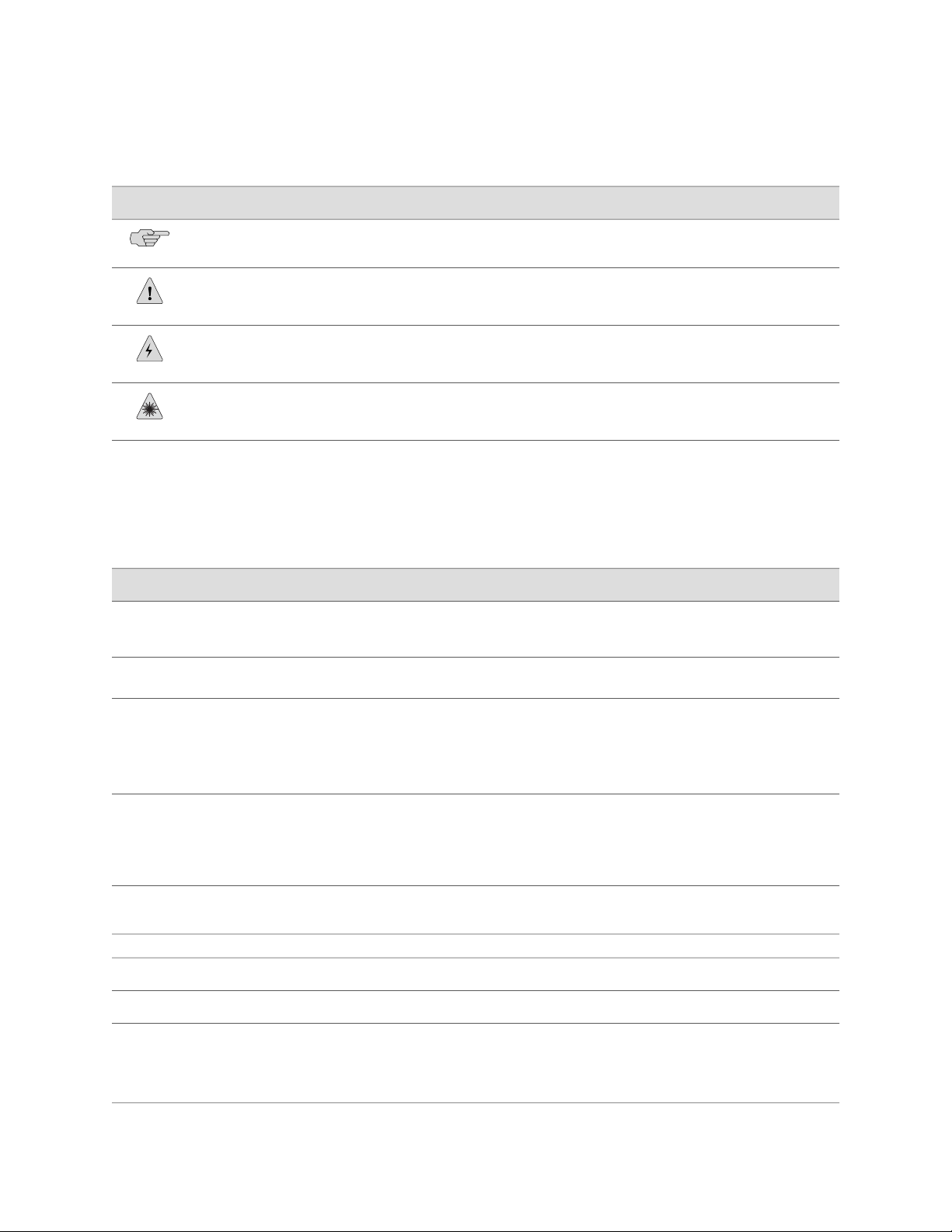
Table 1: Notice Icons
DescriptionMeaningIcon
Indicates important features or instructions.Informational note
Indicates a situation that might result in loss of data or hardware damage.Caution
Alerts you to the risk of personal injury or death.Warning
Alerts you to the risk of personal injury from a laser.Laser warning
Table 2 on page xiv defines text and syntax conventions that we use throughout the
E Series and JUNOSe documentation.
Table 2: Text and Syntax Conventions
Represents commands and keywords in text.Bold text like this
Bold text like this
Fixed-width text like this
Represents text that the user must type.
Represents information as displayed on your
terminal’s screen.
Italic text like this
Emphasizes words.
■
Identifies variables.
■
Identifies chapter, appendix, and book
■
names.
Plus sign (+) linking key names
keys simultaneously.
Syntax Conventions in the Command Reference Guide
ExamplesDescriptionConvention
Issue the clock source command.
■
Specify the keyword exp-msg.
■
host1(config)#traffic class low-loss1
host1#show ip ospf 2
Routing Process OSPF 2 with Router
ID 5.5.0.250
Router is an Area Border Router
(ABR)
There are two levels of access: user and
■
privileged.
clusterId, ipAddress.
■
Appendix A, System Specifications
■
Press Ctrl + b.Indicates that you must press two or more
terminal lengthRepresents keywords.Plain text like this
| (pipe symbol)
or variable to the left or to the right of this
symbol. (The keyword or variable can be
either optional or required.)
xiv ■ E Series and JUNOSe Text and Syntax Conventions
mask, accessListNameRepresents variables.Italic text like this
diagnostic | lineRepresents a choice to select one keyword
Page 15

Table 2: Text and Syntax Conventions (continued)
About the Documentation
ExamplesDescriptionConvention
[ internal | external ]Represent optional keywords or variables.[ ] (brackets)
[ ]* (brackets and asterisk)
that can be entered more than once.
Represent required keywords or variables.{ } (braces)
Obtaining Documentation
To obtain the most current version of all Juniper Networks technical documentation,
see the Technical Documentation page on the Juniper Networks Web site at
http://www.juniper.net/.
To download complete sets of technical documentation to create your own
documentation CD-ROMs or DVD-ROMs, see the Offline Documentation page at
http://www.juniper.net/techpubs/resources/cdrom.html
Copies of the Management Information Bases (MIBs) for a particular software release
are available for download in the software image bundle from the Juniper Networks
Web site athttp://www.juniper.net/.
Documentation Feedback
[ level1 | level2 | l1 ]*Represent optional keywords or variables
{ permit | deny } { in | out }
{ clusterId | ipAddress }
We encourage you to provide feedback, comments, and suggestions so that we can
improve the documentation to better meet your needs. Send your comments to
techpubs-comments@juniper.net, or fill out the documentation feedback form at
https://www.juniper.net/cgi-bin/docbugreport/. If you are using e-mail, be sure to include
the following information with your comments:
■ Document or topic name
■ URL or page number
■ Software release version
Requesting Technical Support
Technical product support is available through the Juniper Networks Technical
Assistance Center (JTAC). If you are a customer with an active J-Care or JNASC support
contract, or are covered under warranty, and need post-sales technical support, you
can access our tools and resources online or open a case with JTAC.
■ JTAC policies—For a complete understanding of our JTAC procedures and policies,
review the JTAC User Guide located at
http://www.juniper.net/customers/support/downloads/7100059-EN.pdf .
Obtaining Documentation ■ xv
Page 16

ERX 11.1.x Hardware Guide
■ Product warranties—For product warranty information, visit
http://www.juniper.net/support/warranty/ .
■ JTAC hours of operation—The JTAC centers have resources available 24 hours a
day, 7 days a week, 365 days a year.
Self-Help Online Tools and Resources
For quick and easy problem resolution, Juniper Networks has designed an online
self-service portal called the Customer Support Center (CSC) that provides you with
the following features:
■
Find CSC offerings: http://www.juniper.net/customers/support/
■
Search for known bugs: http://www2.juniper.net/kb/
■
Find product documentation: http://www.juniper.net/techpubs/
■ Find solutions and answer questions using our Knowledge Base:
http://kb.juniper.net/
■ Download the latest versions of software and review release notes:
http://www.juniper.net/customers/csc/software/
■ Search technical bulletins for relevant hardware and software notifications:
https://www.juniper.net/alerts/
■ Join and participate in the Juniper Networks Community Forum:
http://www.juniper.net/company/communities/
■
Open a case online in the CSC Case Management tool: http://www.juniper.net/cm/
To verify service entitlement by product serial number, use our Serial Number
Entitlement (SNE) Tool: https://tools.juniper.net/SerialNumberEntitlementSearch/
Opening a Case with JTAC
You can open a case with JTAC on the Web or by telephone.
■
Use the Case Management tool in the CSC at http://www.juniper.net/cm/ .
■ Call 1-888-314-JTAC (1-888-314-5822 toll-free in the USA, Canada, and Mexico).
For international or direct-dial options in countries without toll-free numbers, see
http://www.juniper.net/support/requesting support.html .
xvi ■ Requesting Technical Support
Page 17

Part 1
Product Overview
■ ERX Overview on page 3
Product Overview ■ 1
Page 18

ERX 11.1.x Hardware Guide
2 ■ Product Overview
Page 19

Chapter 1
ERX Overview
This chapter provides introductory information about the ERX routers. It contains
the following sections:
■ Overview on page 3
■ ERX Routers on page 3
■ ERX Modules on page 9
■ Network Management Tools on page 14
■ Redundancy Features on page 14
Overview
ERX routers are modular, carrier-class networking devices that deliver performance,
reliability, and service differentiation to both business and consumer Internet users.
The ERX7xx and ERX14xx models offer high port density, low power consumption,
and fully redundant Internet access routing and edge aggregation. The Juniper
Networks ERX310 Broadband Services Router supports the same services, but with
smaller capacity and scaling capabilities. ERX routers offer the complete edge solution
for IP-optimized carriers.
ERX Routers
Five models of ERX routers are available:
■ Juniper Networks ERX1440 Broadband Services Router
■ Juniper Networks ERX1410 Broadband Services Router
■ Juniper Networks ERX710 Broadband Services Router
■ Juniper Networks ERX705 Broadband Services Router
■ Juniper Networks ERX310 Broadband Services Router
All models use the same software. However, the specific model determines the:
■ Combination of line modules supported
■ Conditions for line rate performance of line modules
■ Type, capacity, and number of SRP modules used
Overview ■ 3
Page 20
ERX 11.1.x Hardware Guide
ERX14xx Models
NOTE: In the E Series documentation, the term ERX14xx models refers to both the
ERX1440 and ERX1410 routers. The terms ERX1440 and ERX1410 routers refer to
the specific models. See Figure 1 on page 5 and Figure 2 on page 5.
The ERX1440 router manages an extremely high volume of network traffic, and uses
a 40-Gbps switch route processor (SRP) module, either the SRP-40G or SRP-40G+
module. (The SRP-40G+ module obsoletes the SRP-40G module; however, the
software continues to support both modules.) In this model, all line modules operate
at full wire speed simultaneously.
The ERX1410 router manages high levels of network traffic, and uses the 10-Gbps
SRP module (SRP-10G). You can configure the ERX1410 router to enable the line
modules either to operate at full line rate performance or to allow line modules to
operate at a rate dependent on the resources available. The former option restricts
the allowed combinations of line modules. For information on configuring
performance of line modules, see JUNOSe System Basics Configuration Guide, Chapter 6,
Managing Modules.
NOTE: The 10-Gbps SRP module used in the ERX310 router is different from the
10-Gbps SRP module used in the ERX1410 router. See “SRP Module” on page 9 for
more information.
Externally, the ERX1440 chassis is the same as the ERX1410 chassis. (See Figure 1
on page 5 and Figure 2 on page 5.) Both routers contain 14 vertical slots to
accommodate modules.
Internally, the ERX1440 chassis differs from the ERX1410 chassis, and includes a
special midplane for the 40-Gbps SRP module.
Installation procedures and operating procedures are identical for both systems. All
ERX7xx and ERX14xx models use the same SRP I/O module, but different power
input modules are used.
NOTE: The router may look different from the routers shown in the figures in this
chapter, depending on the line modules in the slots.
4 ■ ERX Routers
Page 21
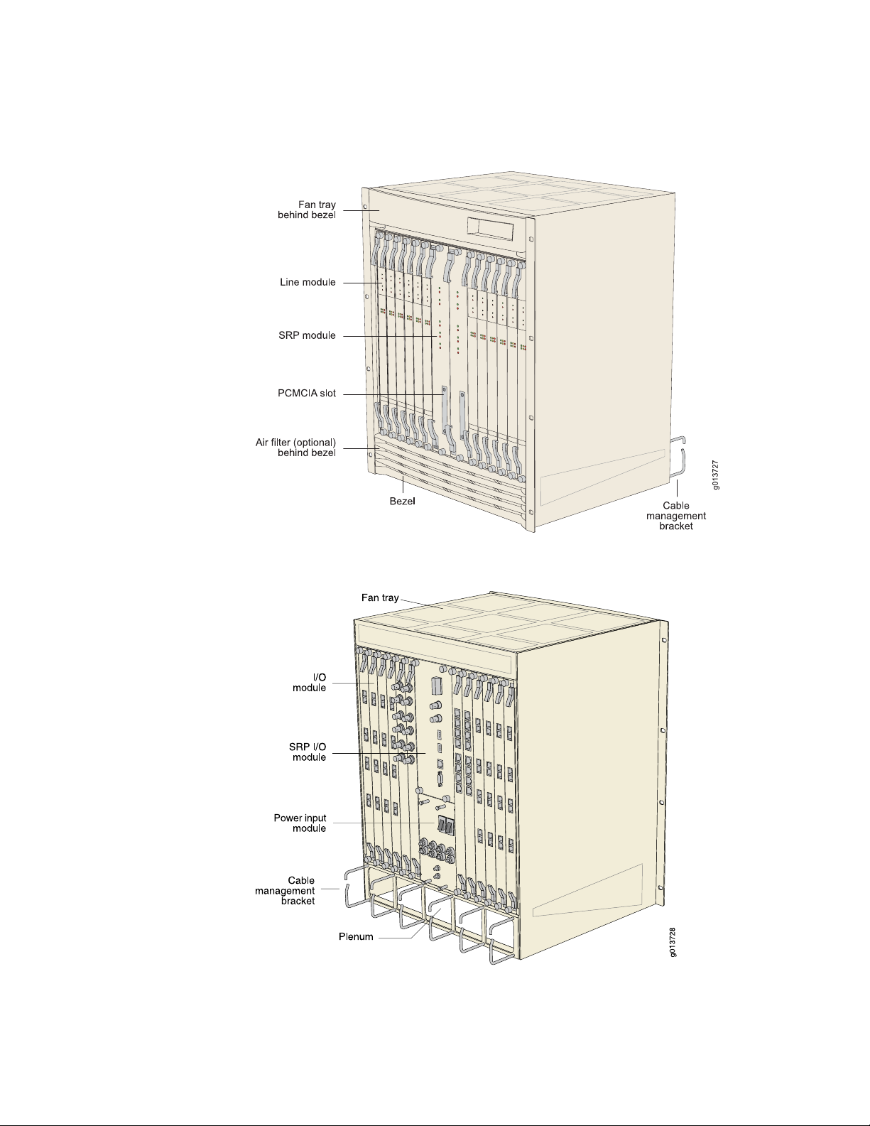
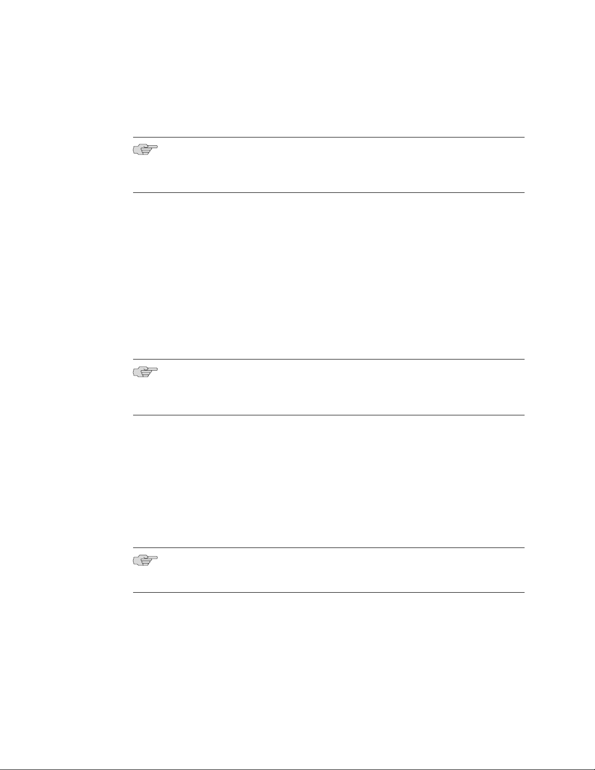
Figure 1: ERX14xx Models, Front View
Chapter 1: ERX Overview
Figure 2: ERX14xx Models, Rear View
ERX Routers ■ 5
Page 22
ERX 11.1.x Hardware Guide
ERX7xx Models
NOTE: In the E Series documentation, the term ERX7xx models refers to both the
ERX705 and ERX710 routers. The terms ERX705 and ERX710 routers refer to the
specific models. See Figure 3 on page 6 and Figure 4 on page 7.
The ERX7xx models are robust, high-density routers with less capacity than the
ERX14xx models. The ERX7xx models use either the SRP-10G module or the SRP-5G
module.
You can configure the ERX7xx models to enable the line modules (LM) to operate
either at full line rate performance or at a rate dependent on the resources available.
For information about configuring performance of line modules, see JUNOSe System
Basics Configuration Guide, Chapter 6, Managing Modules.
NOTE: The 10-Gbps SRP module used in the ERX310 router is different from the
10-Gbps SRP module used in the ERX710 router. See “SRP Module” on page 9 for
more information.
The ERX705 chassis is the same as the ERX710 chassis. (See Figure 3 on page 6
and Figure 4 on page 7.) The chassis contains seven slots to accommodate modules.
Installation procedures and operating procedures are identical for both systems. All
ERX7xx and ERX14xx models use the same SRP I/O module, but different power
input modules are used.
NOTE: The router may look different from the routers shown in the figures in this
chapter, depending on the line modules in the slots.
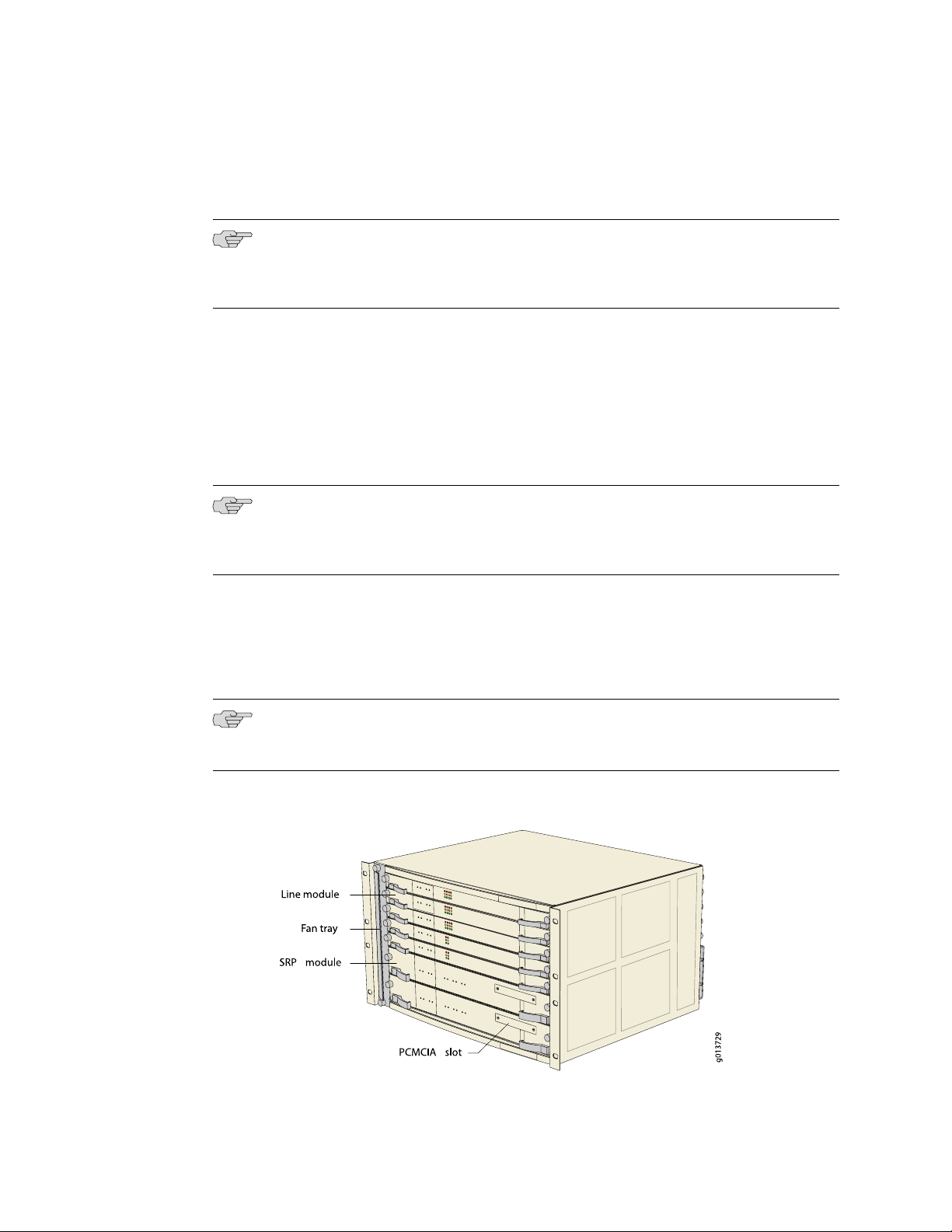
Figure 3: ERX7xx Models, Front View
6 ■ ERX Routers
Page 23
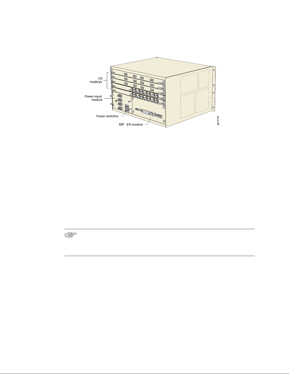
Figure 4: ERX7xx Models, Rear View
ERX310 Broadband Services Router
Chapter 1: ERX Overview
The ERX310 router is a low-end platform that supports all of the same services as
the ERX7xx and ERX14xx models, but with smaller capacity and scaling capabilities.
Like the ERX7xx and ERX14xx models, the ERX310 router uses the same software
architecture, providing a single IP entry point into the network with the same IP-based
protocols and services that are available on other ERX routers. The ERX310 router
is designed to be used as a small distributed POP router as well as a high-end CPE
router.
The ERX310 router is a three-slot chassis with a midplane architecture. One slot
supports one nonredundant 10-Gbps SRP module, while the other two slots support
line modules. The router supports existing E Series ASIC-based line modules (except
the OC48/STM16 line module), as well as a select number of combination cards. The
combination cards provide a fixed combination of interfaces on the I/O module so
that a single slot can support multiple interfaces (ATM OC3 and GE, for example).
NOTE: The 10-Gbps SRP module used in the ERX310 router is different from the
10-Gbps SRP module used in the ERX7xx and ERX14xx models. See “SRP Module”
on page 9 for more information.
The ERX310 router is available in either redundant AC- or DC-powered models.
ERX Routers ■ 7
Page 24
ERX 11.1.x Hardware Guide
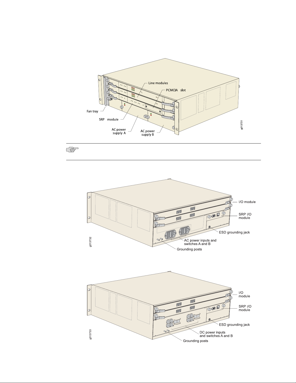
Figure 5: ERX310 Router, Front View (AC Model)
NOTE: The DC model has blank filler panels in power supply slots.
Figure 6: ERX310 Router, Rear View (AC Model)
Figure 7: ERX310 Router, Rear View (DC Model)
8 ■ ERX Routers
Page 25
ERX Modules
Chapter 1: ERX Overview
Each system supports an SRP module and a selection of line modules. You can use
any line module for access or uplink. Access line modules receive traffic from
low-speed circuits, and the system routes the traffic onto higher-speed uplink line
modules and then to the core of the network.
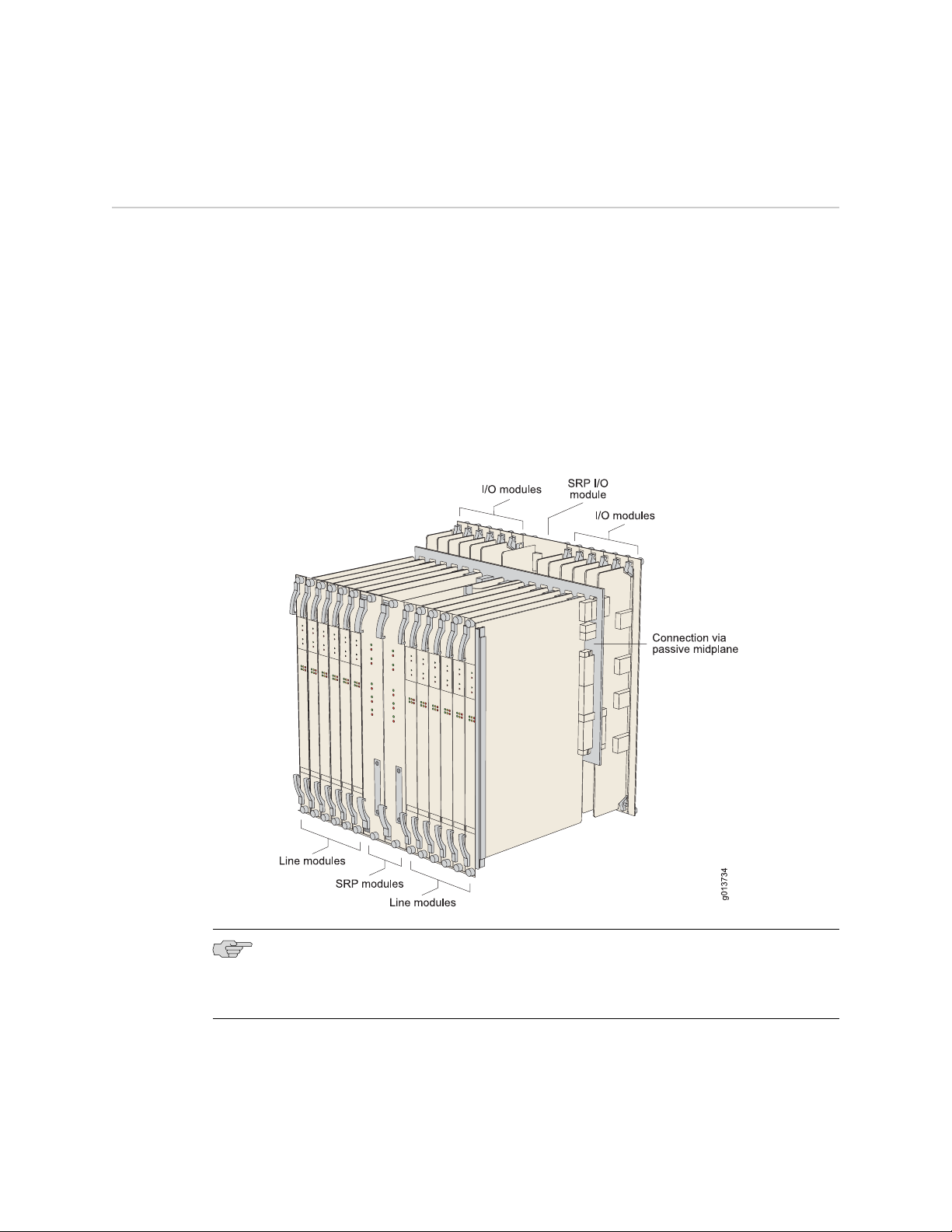
Each module connects to a corresponding I/O module via a passive midplane. See
Figure 8 on page 9.
The front panel of each module contains a collection of status LEDs (light-emitting
diodes). For information about how to interpret the LEDs, see “Troubleshooting” on
page 95.
Figure 8: Modules in ERX14xx Models
SRP Module
NOTE: Some line modules require a minimum amount of memory to be used with
JUNOSe Release 5.3.0 or a higher-numbered release. See the ERX Module Guide for
line module specifications.
Switch route processor (SRP) modules perform system management, routing table
calculations and maintenance, forwarding table computations, statistics processing,
ERX Modules ■ 9
Page 26
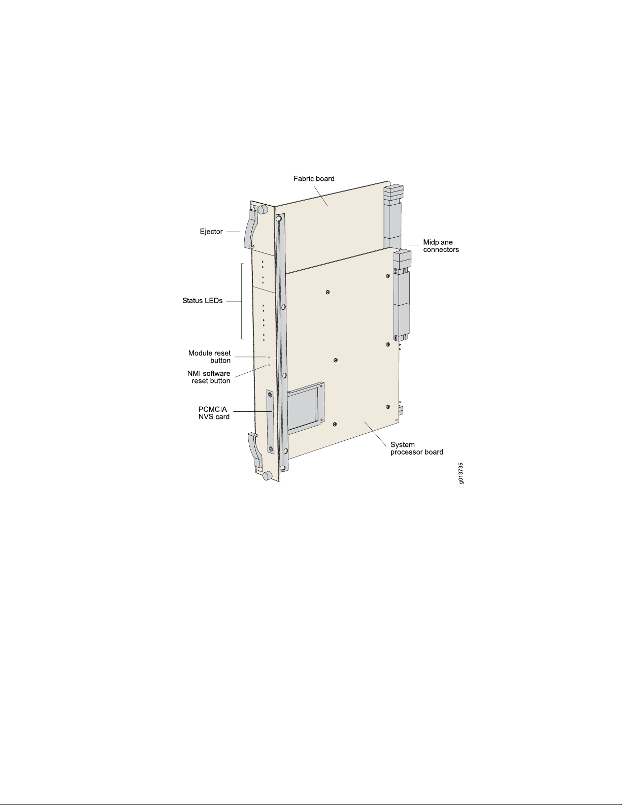
ERX 11.1.x Hardware Guide
configuration storage, and other control plane functions. Each SRP module is a
PowerPC-based system with its own memory, nonvolatile disk storage, and power
supply. (See Figure 9 on page 10 and Figure 10 on page 11.)
Figure 9: SRP Module for ERX7xx and ERX14xx Models
10 ■ ERX Modules
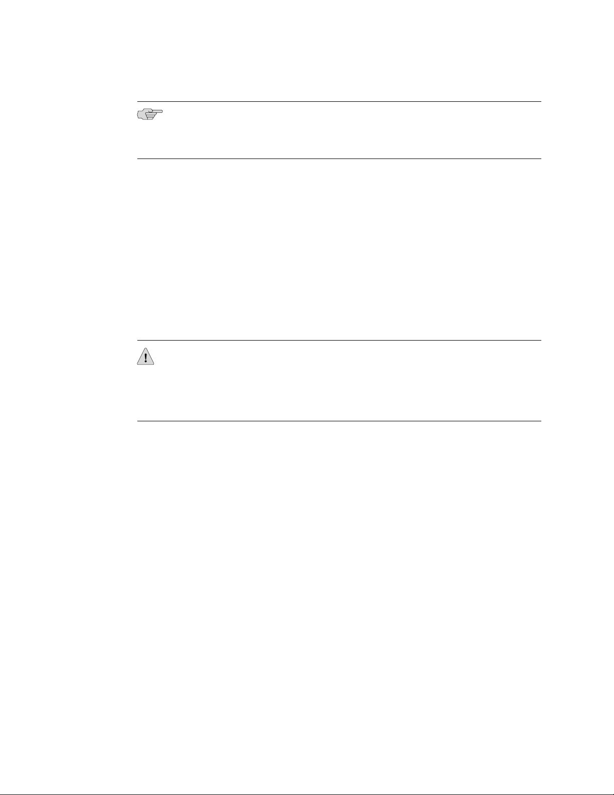
Page 27
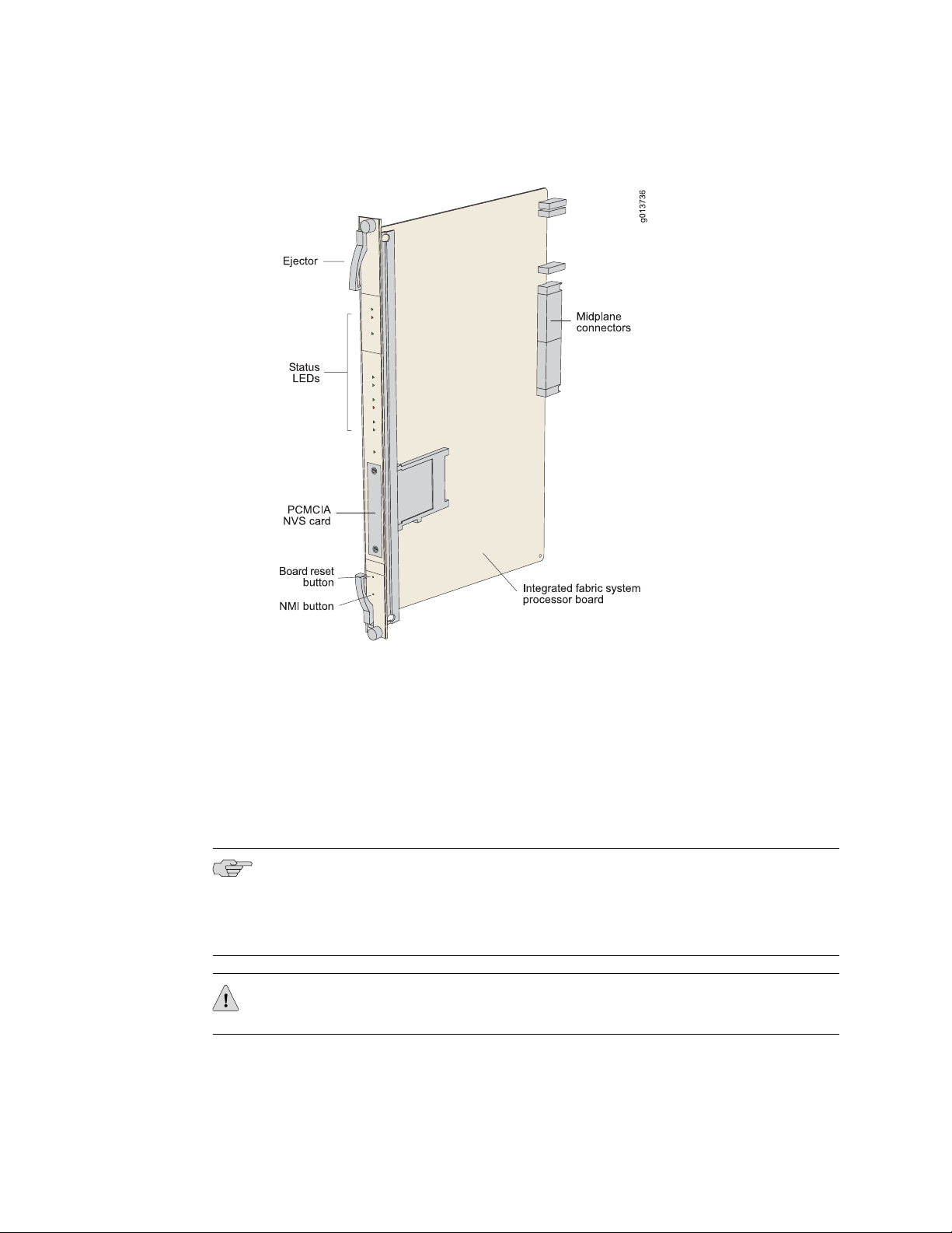
Figure 10: SRP Module for ERX310 Router
Chapter 1: ERX Overview
Module Details
ERX7xx and ERX14xx models use up to two redundant SRP modules operating in
an active/standby configuration. ERX310 router use only one SRP module. An SRP
module must be present for any system to boot.
SRP modules ranging from 5 Gbps to 40 Gbps can be used in ERX7xx and ERX14xx
models. Only a 10-Gbps SRP module (SRP-SE10G) can be used in ERX310 router.
See the ERX Module Guide for complete information.
NOTE: Because of different physical dimensions and switch fabric capabilities, SRP
modules are not interchangeable between systems. For example, the 10-Gbps SRP
module used in ERX7xx and ERX14xx models cannot be used in the ERX310 router,
and vice versa.
CAUTION: Do not remove the SRP module while the system is running.
ERX Modules ■ 11
Page 28
ERX 11.1.x Hardware Guide
NOTE: Some SRP modules require a minimum amount of memory to be used with
JUNOSe Release 5.3.0 or a higher-numbered release. See the ERX Module Guide for
module specifications.
For details about installing SRP modules, see “Installing Modules” on page 31.
SRP Module Redundancy
SRP module redundancy is available only for ERX7xx and ERX14xx models. See
“Redundancy Features” on page 14
Nonvolatile Storage
The PCMCIA slot on the front of the SRP module holds a Type II PCMCIA nonvolatile
storage (NVS) card. (See Figure 9 on page 10 and Figure 10 on page 11.) This card
is loaded with the system's software and configuration files. The PCMCIA card is
factory installed.
SRP I/O Module
CAUTION: Although you can remove PCMCIA NVS (Flash) cards from a running
router, we recommend that you do not do so. If you remove the card while data is
being written to or copied from the NVS card, data can be lost or corrupted. Therefore,
we strongly recommend that you shut down the router before removing a PCMCIA
NVS card.
The SRP I/O module is a single corresponding input/output module that interfaces
with the SRP modules through the system's midplane. The same SRP I/O module
works with all SRP modules, but is router specific. The I/O module used in ERX7xx
and ERX14xx models cannot be used in the ERX310 router, and vice versa. See
Figure 2 on page 5, Figure 4 on page 7, and Figure 6 on page 8 for locations.
Module Details
The SRP I/O module provides standard craft management interfaces, including:
■ 10/100Base-T—The port enables access to the ERX router for Ethernet
management functions via CLI or SNMP, for example.
■ RS-232—The port provides a serial connection for monitoring the system's
hardware configuration through a PC (running terminal emulation software) or
ASCII terminal. Allows direct CLI access.
12 ■ ERX Modules
■ Alarm contacts—The contacts provide for remote indication of critical, major,
and minor router alarms (ERX7xx and ERX14xx models only; currently not
implemented)
■ External timing inputs—The inputs provide a method of ensuring that the clock
timing used by the router remains synchronized with the network's system clock.
Page 29
Line Modules
Chapter 1: ERX Overview
BNC connectors and wire wraps are available for ERX7xx and ERX14xx models
only.
For details about installing the SRP I/O module, see “Installing Modules” on page 31.
Line modules (LM) process data from different types of network connections. For
information about available line modules and which SRP modules support specific
line modules, see the ERX Module Guide.
Figure 11 on page 13 shows a representative line module. For details about installing
line modules, see “Installing Modules” on page 31.
Figure 11: Representative Line Module
Packet Classification
Most line modules support packet classification on ingress; some non-ASIC line
modules do not. A classification engine on the line module matches specific fields
(such as source and destination IP address, source and destination port, and protocol),
the ingress IP interface, layer 2 fields, or some combination of these against
user-configured filters at wire speed.
ERX Modules ■ 13
Page 30

ERX 11.1.x Hardware Guide
I/O Modules
Most line modules have a corresponding input/output (I/O) module that provides the
physical interconnection to the network. Insert each I/O module into the back of the
system, directly behind its corresponding line module.
For information about which line modules pair with which I/O modules, see the ERX
Module Guide. See Figure 2 on page 5, Figure 4 on page 7, and Figure 6 on page 8
for locations. For details about installing I/O modules, see “Installing Modules” on
page 31.
Network Management Tools
You can use different management tools to configure the system to meet the specific
networking requirements.
CLI Management
The CLI provides fully developed and automated configuration and status functionality
through a local RS-232 port, Telnet, or SSH via any reachable network. For a full
discussion of the CLI, see JUNOSe System Basics Configuration Guide, Chapter 2,
Command-Line Interface.
SNMP MIB Management
The system offers a complete SNMP interface for configuration, status, and alarm
reporting. The system supports both Standard and Enterprise MIBs (Management
Information Bases). The Juniper Networks E Series Enterprise MIB is ASN.1 notated
for easy importing into third-party SNMP management applications. For more
information, see JUNOSe System Basics Configuration Guide, Chapter 4, Configuring
SNMP.
NMC-RX Device Management System
The NMC-RX application provides a global method of managing all routers, line
modules, and ports through a graphical user interface.
Redundancy Features
This section describes system redundancy features.
SRP Modules
NOTE: This section applies to ERX7xx and ERX14xx models only. ERX310 routers
contain one SRP module and therefore do not offer SRP module redundancy.
14 ■ Network Management Tools
Page 31

Chapter 1: ERX Overview
ERX7xx and ERX14xx models use a 1:1 redundancy scheme for the SRP module.
When two SRP modules of the same type are installed in the chassis, one acts as a
primary (active) and the second as a redundant (standby) module. Both SRP modules
share a single SRP I/O module located in the rear of the chassis.
If the standby SRP module detects that the primary SRP module is not active (and
high-availability mode is not enabled), it reboots the system and takes control. If
high-availability mode has been enabled, automatic switchover occurs with near
hitless failover. If you upgrade software, you must copy the software to the redundant
SRP and reboot it. For information about configuring and managing SRP module
redundancy, see JUNOSe System Basics Configuration Guide, Chapter 6, Managing
Modules.
After you install two SRP modules, the modules negotiate for the primary role. A
number of factors determine which module becomes the primary; however,
preference is given to the module in the lower-numbered slot. The SRP modules
record their latest roles and retain them the next time you switch on the system. For
information about installing SRP modules, see “Installing Modules” on page 31.
NVS Cards
If you have two SRP modules installed in a system, you can use NVS cards of different
capacities on the SRP modules. The effective capacity of the higher-capacity NVS
card will equal that of the lower-capacity NVS card. For information about installing
NVS cards, see “Installing Modules” on page 31.
When you install new NVS cards or SRP modules, you must issue the synchronize
command to match the file system of the NVS card on the redundant SRP module
with the file system of the NVS card on the primary SRP module. (The NVS card on
the redundant SRP module will hereafter be referred to as the redundant NVS card;
the NVS card on the primary SRP module will hereafter be referred to as the primary
NVS card.)
If the capacity of the primary NVS card is equal to or smaller than that of the
redundant NVS card, the system copies all the files from the primary NVS card to
the redundant NVS card. However, if the capacity of the primary NVS card exceeds
that of the redundant NVS card, the system creates an invisible synchronization
reserve file on the primary NVS card, provided that there is enough space for the
file.
The purpose of the synchronization file is to prevent the creation of data that cannot
fit on the redundant NVS card. The file contains no useful data, and is not visible
when you view the files in NVS. The size of the file is equal to the difference in
capacities of the two NVS cards. For example, if the primary NVS card has a capacity
of 224 MB and the redundant NVS card has a capacity of 220 MB, the size of the
synchronization file is 4 MB, and only 220 MB of space is available on the primary
NVS card.
If the primary NVS card does not have enough space to create the synchronization
reserve file, the synchronize command fails, and a warning message is displayed
on the console. To resolve this issue, either delete unwanted files from the primary
NVS card or replace the redundant NVS card with a higher-capacity NVS card.
Redundancy Features ■ 15
Page 32

ERX 11.1.x Hardware Guide
Line Modules
NOTE: This section applies to ERX7xx and ERX14xx models only. ERX310 routers
do not offer line module redundancy.
ERX7xx and ERX14xx models support line module redundancy for several line
modules. For details about which line modules support redundancy, see the ERX
Module Guide. In this scheme, an extra line module in a group of identical line modules
provides redundancy in case of line module failure. To use this feature, you need a:
■ Spare line module
■ Redundancy midplane
■ Redundancy I/O module
A redundancy midplane can cover 3–6 slots. It provides additional connectivity that
enables the spare line module to take control of the I/O module associated with any
failed line module in the redundancy group. The spare I/O module provides
connectivity from the spare line module to the redundancy midplane.
The process by which the system switches to the spare line module is called
switchover. When switchover occurs, the system:
1. Breaks the connection between the primary I/O module and the primary line
module.
2. Connects the primary I/O module to the spare line module via the redundancy
midplane and redundancy I/O module.
Protocol processing then takes place on the spare line module.
Figure 12 on page 17 shows the data flow when a spare line module becomes active.
16 ■ Redundancy Features
Page 33

Figure 12: Data Flow When a Spare Line Module Is Active
Chapter 1: ERX Overview
Power
Fans
For information about installing modules for line module redundancy, see “Installing
Modules” on page 31. For information about configuring and managing SRP module
redundancy, see JUNOSe System Basics Configuration Guide, Chapter 6, Managing
Modules.
All E Series routers provide a power architecture that distributes redundant –48 VDC
feeds through the router to each line module, SRP module, and fan module where
DC-to-DC converters provide local conversion to the required secondary voltages.
The ERX310 router is available with either DC or AC power inputs. The AC-powered
version can be configured with one or two hot-swappable power supplies for optional
redundancy. (See Figure 5 on page 8 and Figure 6 on page 8.) The power supplies
convert AC power to internal –48 V redundant DC feeds that are then distributed
through the router.
Forced air-cooling keeps the temperature of the E Series modules and components
within normal operating limits. In ERX14xx models, six cooling fans are located in
a tray at the top of the router (Figure 1 on page 5). In ERX7xx models, four cooling
fans are located in a tray on one side of the router (Figure 3 on page 6). In the
Redundancy Features ■ 17
Page 34

ERX 11.1.x Hardware Guide
ERX310 router, two cooling fans are located in a tray on one side of the router (Figure
5 on page 8).
The system monitors the temperature of each module. If the temperature of a module
exceeds the maximum limit, the system immediately goes into thermal protection
mode and the modules are powered off. The ERX system controller enters a low
power mode, keeps the modules in a power-off condition, and does not respond to
any management interface commands. For information about troubleshooting high
operating temperatures, see “Troubleshooting” on page 95.
In ERX7xx and ERX14xx models, the fan tray has two redundant converters that
power the fans (for the ERX14xx models, a –24 V, 50 W converter; for the ERX7xx
models, a –12 V, 15 W converter). If one converter fails, the other takes over. The
ERX310 router does not have redundant converters.
For all E Series routers, the system software reports an alarm if any of the fans or
converters fail.
18 ■ Redundancy Features
Page 35

Part 2
Initial Installation
■ Unpacking and Inspecting ERX Routers on page 21
■ Installing ERX Routers on page 25
■ Installing Modules on page 31
■ Cabling ERX Routers on page 47
■ Powering Up ERX Routers on page 65
■ Accessing ERX Routers on page 69
Initial Installation ■ 19
Page 36

ERX 11.1.x Hardware Guide
20 ■ Initial Installation
Page 37

Chapter 2
Unpacking and Inspecting ERX Routers
This chapter reviews shipping contents and unpacking procedures for ERX routers.
It contains the following sections:
■ Before You Begin on page 21
■ Unpacking ERX14xx Models on page 21
■ Unpacking ERX7xx Models and ERX310 Broadband Services Routers on page 22
■ Inspecting Router Components and Accessories on page 22
■ If You Detect or Suspect Damage on page 23
■ Contacting Juniper Networks on page 23
■ The Next Step on page 23
Before You Begin
Before you begin unpacking the router, be sure you have the following tools:
■ A No. 2 Phillips screwdriver
■ A utility knife
■ A mechanical lift, or at least two people to assist in lifting
Unpacking ERX14xx Models
ERX14xx models come boxed, bolted, and strapped to a skid. For your convenience,
we recommend that you unpack the router in the location where you want to install
it.
WARNING: Three people are required to install the router in a rack: two to lift the
system into position and one to screw it to the rack.
To unpack ERX14xx models:
1. Cut the two straps that secure the carton to the skid, open the carton from the
top, and remove the box of accessories that sits on top of the router.
2. Unlock the four plastic clips that hold the box to the skid by squeezing them in
their center and pulling out, and then lift the carton off the router.
Before You Begin ■ 21
Page 38

ERX 11.1.x Hardware Guide
3. Remove the three screws that attach each of the two L-brackets to the router.
4. To avoid scratching the router when removing it from the skid, detach one of
the L-brackets from the skid by removing the three screws. See Figure 13 on
page 22.
Figure 13: Removing an L-Bracket
Unpacking ERX7xx Models and ERX310 Broadband Services Routers
ERX7xx models and ERX310 routers are shipped boxed, but not attached to a skid.
For your convenience, we recommend that you unpack the router in the location
where you want to install it.
To unpack an ERX7xx model or an ERX310 router:
1. Open the carton from the top.
2. Remove the box of accessories that sits on top of the system.
3. Remove the router from the box.
WARNING: Three people are required to install the router in a rack: two to lift the
system into position and one to screw it to the rack.
Inspecting Router Components and Accessories
After you remove the equipment from the shipping containers:
22 ■ Unpacking ERX7xx Models and ERX310 Broadband Services Routers
Page 39

■ Confirm the contents of each container.
■ Inspect all external surfaces and external connectors for visible signs of damage.
■ Inspect all accessories shipped with each unit.
■ Document any damage noted during your inspection.
■ Confirm that the router has the correct number and type of modules for your
ordered configuration.
If You Detect or Suspect Damage
If you detect or suspect damage to any equipment:
■ Contact the shipper responsible for delivery, and formally report the damage.
■ Contact your Juniper Networks sales representative or reseller.
Chapter 2: Unpacking and Inspecting ERX Routers
Contacting Juniper Networks
Please contact Juniper Networks at 1-888-314-JTAC (from the United States, Canada,
or Mexico) or 408-745-9500 (from elsewhere), or contact your sales representative
if you have any questions or concerns. See “Contacting Customer Support and
Returning Hardware” on page 139 for complete contact information.
The Next Step
■ To familiarize yourself with the electrical, environmental, and other guidelines
and requirements for installing ERX routers, turn to “Installation Guidelines and
Requirements” on page 117.
■ If you are familiar with these guidelines and requirements, turn to “Installing
ERX Routers” on page 25.
If You Detect or Suspect Damage ■ 23
Page 40

ERX 11.1.x Hardware Guide
24 ■ The Next Step
Page 41

Chapter 3
Installing ERX Routers
This chapter describes how to install ERX routers in a rack. It contains the following
sections:
■ Before You Begin on page 25
■ Freestanding Installation on page 25
■ Rack-Mounted Installation on page 26
■ The Next Step on page 29
Before You Begin
Before installing E Series routers, be sure you:
■ Have a plan for installing the routers that takes into consideration future
expansion of your system.
■ Have the tools and accessories needed to complete the installation.
■ Read and understand the clearance requirements for the front and back of the
chassis for cable routing and other unit access. See “Environmental
Requirements” on page 117 for more information.
■ Read and understand the clearance requirements for the chassis to ensure
adequate ventilation.
■ Prepare the equipment racks by measuring and marking space for each router
and plenum you plan to install.
Freestanding Installation
When installing the system on a table top or in any other freestanding mode, be sure
to leave enough space around the system for adequate ventilation. Position the router
with easy access to the connections that it needs for power, local communications,
and remote communications.
See “Installation Guidelines and Requirements” on page 117, and “System
Specifications” on page 109, for more information.
WARNING: Two people are required to lift an E Series router.
Before You Begin ■ 25
Page 42

ERX 11.1.x Hardware Guide
CAUTION: To prevent electrostatic damage to the system and its components, make
sure persons handling the router wear an antistatic device.
Connectors are located on the I/O modules and the power input module. These
modules are installed from the rear of the router. (See Figure 14 on page 26.) See
“Cabling ERX Routers” on page 47 for cabling installation procedures.
Figure 14: ERX7xx Models, Rear View
Rack-Mounted Installation
We recommend that you use a standard EIA distribution rack. See “Equipment Rack
Requirements” on page 121 for detailed rack information.
Installation Guidelines
Before installing the systems in a rack, consider the following guidelines and refer
to Figure 15 on page 27:
■ You can install up to 3 ERX14xx models, 6 ERX7xx models, or 14 ERX310 routers
in a single 7-ft. (2.1 m) rack.
Installing multiple systems in a single rack enables you to maximize your available
space.
■ You can install an ERX14xx model, an ERX7xx model, and an ERX310 router
together in the same rack. (See Figure 15 on page 27.)
CAUTION: If you install an ERX7xx model or ERX310 router directly above an
ERX14xx model in the same rack, you must install a plenum between the ERX7xx
model or ERX310 router and the ERX14xx model so that the air can circulate between
the systems. (See Figure 53 on page 124.) This plenum is available from Juniper
Networks.
26 ■ Rack-Mounted Installation
Page 43

ERX310 router
ERX7xx model
Plenum
ERX14xx model
Chapter 3: Installing ERX Routers
If you install an ERX14xx model above an ERX7xx model or ERX310 router,
there is no need to install a plenum between the units because the ERX7xx
models and ERX310 routers vent air out the side of the chassis.
■ Install heavier systems, such as an ERX14xx model, on the bottom of the rack.
Mount lighter systems, such as the ERX310 router, higher in the rack.
Figure 15: ERX Routers Installed in Recommended Order
Safety Guidelines
Observe the following safety guidelines when mounting the router in a rack.
WARNING: Install equipment in the rack from the bottom upward. This helps to
maintain the stability of the rack and reduces the chance of the rack tipping over.
Rack-Mounted Installation ■ 27
Page 44

ERX 11.1.x Hardware Guide
WARNING: Three people are required to install the router in a rack: two to lift the
system into position and one to screw it to the rack.
CAUTION: Evaluate the overall loading of the branch circuit before you install any
equipment into a rack.
WARNING: Connect the router or rack to ground (earth), and ensure that a reliable
grounding path is maintained in the rack.
WARNING: Do not work on the system or connect or disconnect cables during
lightning activity.
WARNING: Be sure circuit breakers for the power source are in the OFF position
before attaching power cables.
WARNING: Before servicing the router, turn off the power.
WARNING: Remove jewelry (including rings, necklaces, and watches) before working
on equipment that is connected to power lines. Metal objects heat up when connected
to power and ground and can cause serious burns or become welded to the terminals.
WARNING: Do not insert any metal object, such as a screwdriver, into an open slot
or the backplane. Doing so can cause electric shock and serious burns.
WARNING: The ERX310 router AC model has more than one power-supply cord.
Disconnect two power cords before servicing to avoid electric shock.
Preparing the Equipment Racks
Following your installation plan, use a tape measure and marking pen to measure
and mark space on each equipment rack for each router component. For horizontal
spacing, follow Network Equipment Building System (NEBS) requirements. If you
choose not to install a plenum, be sure to include 2 U of space between each chassis
for proper exhaust. A plenum, however, is highly recommended.
28 ■ Rack-Mounted Installation
Page 45

Installing the Router
Chapter 3: Installing ERX Routers
To complete the installation of the router in a rack, you need:
■ A No. 2 Phillips screwdriver
■ Depending on the router, up to eight 10-32 x 3/8 Phillips screws (provided with
the router) for each router to be installed
WARNING: Three people are required to install the router in a rack: two to lift the
system into position and one to screw it to the rack.
CAUTION: Make sure all persons handling a router wear an antistatic device.
The Next Step
To install the router in the rack:
1. With one person standing on the left side of the router and another standing on
the right side, lift the router into the rack.
2. Position the router in its designated location in the equipment rack. Make sure
the holes of the mounting brackets align evenly with the holes of the equipment
rack on both sides.
3. Starting at the bottom, have the third person secure the router in the equipment
rack by using the 10-32 x 3/8 Phillips screws.
4. Connect the necessary cables. (See “Cabling ERX Routers” on page 47 for
instructions on installing the cables.)
Figure 15 on page 27 illustrates a distribution rack with one ERX310 router, one
ERX7xx model, and one ERX14xx model installed.
After you finish installing the router:
■ If you need to install any modules, see “Installing Modules” on page 31.
■ If the router was delivered with the modules already installed, see “Cabling ERX
Routers” on page 47 for instructions on connecting cables.
The Next Step ■ 29
Page 46

ERX 11.1.x Hardware Guide
30 ■ The Next Step
Page 47

Chapter 4
Installing Modules
This chapter describes how to install and remove E Series modules. For information
about managing installed modules, see JUNOSe System Basics Configuration Guide,
Chapter 6, Managing Modules.
This chapter contains the following sections:
■ Overview on page 31
■ Safety Guidelines on page 36
■ Installing SRP I/O and SRP Modules on page 37
■ Installing Line and I/O Modules on page 40
■ Removing a Line Module, SRP Module, or SRP I/O Module on page 41
■ Installing Components for Line Module Redundancy on page 42
■ Configuring Line Module Redundancy on page 46
■ The Next Step on page 46
Overview
Line module slots are located in the front of each ERX chassis, while I/O module slots
are located in the rear. See “ERX Overview” on page 3 for front and rear views of
ERX routers.
In ERX14xx models, modules mount vertically in a chassis with 14 slots. In ERX7xx
models and ERX310 Broadband Services Routers, modules mount horizontally in a
chassis with 7 slots and 3 slots, respectively. See Figure 16 on page 32.
Overview ■ 31
Page 48

ERX7xx model
ERX14xx model ERX310 router
ERX 11.1.x Hardware Guide
Figure 16: Orientation of Line Modules in ERX Routers
Slot Groups
For details about available line modules and compatibility between line modules and
SRP modules, see the ERX Module Guide.
The slots in the ERX1410 router and ERX7xx models are divided into groups. The
number of groups and number of slots per group depend on the system.
There are no slot groups in the ERX1440 or the ERX310 router. In the ERX310 router,
slot 0 contains the SRP module and slots 1 and 2 each contain a line module.
Slot Groups for the ERX1410 Router
A slot group in the ERX1410 router comprises three adjacent chassis slots. The groups
for the ERX1410 router consist of the following slots (Figure 17 on page 33):
■ Slot group 1—Slots 0 through 2
■ Slot group 2—Slots 3 through 5
■ Slot group 3—Slots 8 through 10
■ Slot group 4—Slots 11 through 13
Slots 6 and 7 are reserved for the SRP modules.
32 ■ Overview
Page 49

Figure 17: ERX1410 Slot Groups
Chapter 4: Installing Modules
Slot Groups for the ERX7xx Models
A slot group in an ERX7xx model comprises one slot or two adjacent slots. The groups
for an ERX7xx model consist of the following slots (Figure 18 on page 33):
■ Slot group 1—Slots 2 and 3
■ Slot group 2—Slot 4
■ Slot group 3—Slot 5
■ Slot group 4—Slot 6
Slots 0 and 1 are reserved for the SRP modules.
Figure 18: ERX7xx Model Slot Groups
Combinations of Line Modules In Slot Groups
For information about combinations of line modules in slot groups, see JUNOSe
System Basics Configuration Guide, Chapter 6, Managing Modules.
Overview ■ 33
Page 50

ERX 11.1.x Hardware Guide
OC48 Line Modules
GE-2 Line Modules
The ERX1440 router with the SRP-40G+ SRP module supports OC48 line modules.
Other ERX routers do not support OC48 line modules.
An OC48 line module spans two slots in an ERX1440 router. You can install this line
module only in slots 2–3 and slots 4–5. Other slots in the system do not support this
line module.
The corresponding OC48 Frame APS I/O module spans only one slot. Install the I/O
module in the lower of the slots (either slot 2 or slot 4) that the line module spans.
The ERX1440 router with the SRP-40G+ SRP module supports GE-2 line modules
in all slots; however, full bandwidth is delivered only when the line module is in slot
2 or slot 4. The line module can be used with other SRP modules, but maximum line
performance will not be achieved.
The ERX310 router with the SRP-SE10G SRP module supports GE-2 line modules in
both slots (1 and 2). Maximum line performance is achieved in either slot.
Other ERX routers do not support GE-2 line modules.
Managing Modules Using the Software
For information about software procedures associated with replacing and managing
modules, see JUNOSe System Basics Configuration Guide, Chapter 6, Managing Modules.
Hot-Swapping Modules
All ERX routers support hot-swapping of modules. Hot-swapping enables you to add
or remove a module without powering down the system.
Protecting Modules and Slots
Each ERX chassis has an ESD (electrostatic discharge) grounding jack. See Table 3
on page 35 for locations. To prevent damage from electrostatic discharge, connect
an antistatic wrist strap to the jack when handling components.
34 ■ Overview
Page 51

Chapter 4: Installing Modules
Figure 19: Connecting the Wrist Strap to the ERX310 Router (Rear)
Table 3: Grounding Jack Locations
LocationE Series Router
ERX14xx models
ERX310 router
Front: inside front bezel in lower-left corner
Rear: upper-right corner
Rear: lower-right cornerERX7xx models
Front: lower-left corner
Rear: lower-right corner
To protect the modules and slots when installing modules, observe the following
guidelines:
CAUTION: When handling modules, use an antistatic wrist strap connected to the
router's ESD grounding jack. This action helps to protect the module from damage
by electrostatic discharge.
CAUTION: Always handle the module by its edges. Do not touch the components,
pins, leads, or solder connections.
CAUTION: If you meet strong resistance when attempting to seat the module using
the ejectors, remove it from the chassis and confirm that the slot is designed to hold
the module. Then verify, if applicable, that the module matches its corresponding
module (I/O module or line module). Also, be sure that you have aligned the top and
bottom edges in the correct matching tracks.
Overview ■ 35
Page 52

ERX 11.1.x Hardware Guide
Order of Installation
CAUTION: Be sure to cover every empty slot with a blank filler panel to protect the
system from dust or other foreign substances and to ensure proper system cooling.
CAUTION: Do not discard the antistatic bag. When a module is not in use, store it
in an antistatic bag.
Before you attempt to install or replace a line module (inserted in the front of the
chassis), make sure the corresponding I/O module (inserted in the rear of the chassis)
is already in place. The slot diagnostics run when a line module is installed in a chassis
slot. If the corresponding I/O module is not present, the diagnostics fail, and you
need to remove and reinsert the module.
Required Tools and Safety Items
You need the following tools to install a line module:
■ A No. 2 Phillips screwdriver
■ An ESD wrist strap
Safety Guidelines
Before and during the installation process, observe the following precautions:
WARNING: Do not work on the system or connect or disconnect cables during
lightning activity.
WARNING: Be sure circuit breakers for the power source are in the OFF position
before attaching power cables.
WARNING: Remove jewelry (including rings, necklaces, and watches) before working
on equipment that is connected to power lines. Metal objects heat up when connected
to power and ground and can cause serious burns or become welded to the terminals.
36 ■ Safety Guidelines
WARNING: Do not insert any metal object, such as a screwdriver, into an open slot
or the backplane. Doing so can cause electric shock and serious burns.
Page 53

WARNING: Never attempt to repair parts of modules yourself. Only trained customer
service personnel are authorized to service parts. Call Juniper Networks Customer
Service to make arrangements to return defective modules for repair.
Installing SRP I/O and SRP Modules
You must install SRP modules in specific slots in each router. See Table 4 on page 37
for SRP module slot assignments.
Table 4: SRP Module Slot Assignments
Chapter 4: Installing Modules
SlotRouter
6 and 7ERX14xx models
NOTE: Because of different physical dimensions and switch fabric capabilities, SRP
modules are not interchangeable between systems. For example, the 10-Gbps SRP
module used in ERX7xx and ERX14xx models cannot be used in an ERX310 router,
and vice versa.
NOTE: Install the SRP I/O module before you install the SRP module; otherwise, the
system diagnostics will fail.
Installing an SRP I/O Module
To install an SRP I/O module:
1. Ground yourself by using an antistatic wrist strap or other device and connect
it to the ESD grounding jack on the chassis.
2. With a No. 2 Phillips screwdriver, loosen the captive screws that secure the blank
filler panel covering the empty chassis slot, if present, and remove the filler
panel.
0 and 1ERX7xx models
0ERX310 router
3. Remove the SRP I/O module from its antistatic bag, being careful not to touch
module components, pins, leads, or solder connections.
4. Slide the module into the chassis by placing it between the guides of the selected
slot and pushing the module until it stops.
Installing SRP I/O and SRP Modules ■ 37
Page 54

ERX 11.1.x Hardware Guide
NOTE: See the figures in “ERX Overview” on page 3 for module locations.
5. Tighten the module's captive screws using a No. 2 Phillips screwdriver. Turn
CAUTION: Do not overtighten the screws.
Installing an SRP Module
To install an SRP module:
1. Ground yourself by using an antistatic wrist strap or other device and connect
both screws several times before tightening them completely to allow the module
to sit correctly.
it to the ESD grounding jack on the chassis.
NOTE: See the figures in “ERX Overview” on page 3 for module locations.
2. Choose the slot in which you want to install the module.
■ ERX14xx models—Slot 6 or 7
■ ERX7xx models—Slot 0 or 1
■ ERX310 router—Slot 0
3. With a No. 2 Phillips screwdriver, loosen the captive screws that secure the blank
filler panel covering the empty chassis slot, if present, and remove the filler
panel.
4. Remove the SRP module from its antistatic bag, being careful not to touch module
components, pins, leads, or solder connections.
5. Verify that the ejectors are in the open position, as shown in Figure 20 on
page 39.
38 ■ Installing SRP I/O and SRP Modules
Page 55

Figure 20: Ejectors in the Open Position
Chapter 4: Installing Modules
6. Slide the module into the chassis by placing it between the guides of the selected
slot and pushing the module until it stops.
The module stops sliding when the ejectors make contact with the front of the
chassis.
CAUTION: If you meet strong resistance when attempting to seat the module using
the ejectors, remove it from the chassis and confirm that the slot is designed to hold
the module. Then verify, if applicable, that the module matches its corresponding
module (I/O module or line module). Also, be sure that you have aligned the top and
bottom edges in the correct matching tracks.
7. Insert the module into the backplane by simultaneously depressing both ejectors
(as shown in Figure 20 on page 39) and exerting forward pressure on the module.
8. Tighten the module's captive screws using a No. 2 Phillips screwdriver. Alternately
turn each screw several times before tightening them completely to allow the
module to sit correctly.
CAUTION: Do not overtighten the screws.
Installing SRP I/O and SRP Modules ■ 39
Page 56

ERX 11.1.x Hardware Guide
Installing Line and I/O Modules
This section describes the procedures for installing line and I/O modules.
NOTE: Install the I/O module before you install the corresponding line module;
otherwise, the diagnostics fail and the line module's status is listed as inactive when
you issue the show version command. If this occurs, remove and reinsert the line
module.
Installing a Line Module or an I/O Module
To install a module:
1. Ground yourself by using an antistatic wrist strap or other device and connect
it to the ESD grounding jack on the chassis.
2. Choose the slot where you want to insert the module.
NOTE: Line modules are in the front of the system and I/O modules are in the back
of the system.
Table 5: Module Slot Assignments
Module SlotRouter
ERX1440 router
Router
Router
Install modules other than the OC48 modules in slots
■
0–5 and slots 8–13
Install the OC48 line module in slots 2–3 and slots 4–5
■
Install the corresponding I/O module only in the lower
■
of the two slots (either slot 2 or slot 4) that the line
module spans
Install modules in slots 0–5 and slots 8–13ERX1410 Broadband Services
Install modules in slots 2–6ERX7xx models
Install modules in slots 1–2ERX310 Broadband Services
3. With a No. 2 Phillips screwdriver, loosen the screws that secure the blank filler
panel covering the empty chassis slot, if present, and remove the filler panel.
4. Remove the module from its antistatic bag, being careful not to touch module
components, pins, leads, or solder connections.
5. Verify that the ejectors are in the open position, as shown in Figure 20 on
page 39.
40 ■ Installing Line and I/O Modules
Page 57

Chapter 4: Installing Modules
6. Guide the module into the chassis by placing it between the guides of the selected
slot and pushing the module until it stops.
The module stops sliding when the ejectors make contact with the front of the
chassis.
CAUTION: If you meet strong resistance when attempting to seat the module using
the ejectors, remove it from the chassis and confirm that the slot is designed to hold
the module. Then verify, if applicable, that the module matches its corresponding
module (I/O module or line module). Also, be sure that you have aligned the top and
bottom edges in the correct matching tracks.
7. Insert the module into the midplane by simultaneously depressing both ejectors
(as shown in Figure 20 on page 39) and exerting forward pressure on the module.
8. Tighten the module's captive screws using a No. 2 Phillips screwdriver. Alternately
turn each screw several times before tightening them completely to allow the
module to sit correctly.
CAUTION: Do not overtighten the screws.
Removing a Line Module, SRP Module, or SRP I/O Module
NOTE: We recommend that you issue the slot disable command from the CLI before
removing a line module or I/O module.
CAUTION: If you do not use the halt command before removing or powering down
an SRP, the system's NVS card can become corrupted.
To remove a line module, SRP module, or SRP I/O module:
1. For SRP modules and SRP I/O modules, issue the appropriate halt command
(halt, halt primary-srp, or halt standby-srp).
See JUNOSe System Basics Configuration Guide, Chapter 6, Managing Modules for
information about the halt commands.
2. Ground yourself by using an antistatic wrist strap or other device and connect
it to the ESD grounding jack on the chassis.
3. Use a screwdriver (using a No. 2 Phillips screwdriver, if necessary) to loosen the
thumb screws located at the top and bottom of the module panel.
4. If the module has ejector handles, pull them to the open position, as shown in
Figure 21 on page 42.
Removing a Line Module, SRP Module, or SRP I/O Module ■ 41
Page 58

ERX 11.1.x Hardware Guide
Figure 21: Ejectors in the Closed Position
5. Carefully slide the module out of the chassis.
6. Place the module in its antistatic bag, being careful not to touch module
components, pins, leads, or solder connections.
7. Cover the empty chassis slot with a blank filler panel, and tighten the filler panel's
captive screws using a No. 2 Phillips screwdriver. Turn both screws several times
before tightening them completely.
CAUTION: Do not overtighten the screws.
If you remove an I/O module and not the corresponding line module, the line module
reboots. Its status becomes inactive when you issue the show version command.
If you remove a line module and do not delete the corresponding configuration, the
status of the line module is listed as not present when you issue the show version
command.
Installing Components for Line Module Redundancy
A spare line module provides redundancy for a group of identical line modules for
ERX7xx and ERX14xx models only.
42 ■ Installing Components for Line Module Redundancy
Page 59

Chapter 4: Installing Modules
NOTE: The ERX310 router does not support line module redundancy.
For line module redundancy to operate, you must install:
■ The line modules, including the spare line module
■ The redundancy midplane
■ The I/O modules, including the spare I/O module
For more information, see “Redundancy Features” on page 14.
WARNING: Do not insert any metal object, such as a screwdriver, or place your hand
into an open slot or the backplane when the router is on. Remove jewelry (including
rings, necklaces, and watches) before working on equipment that is connected to
power lines. These actions can prevent electric shock and serious burns.
CAUTION: When handling modules, use an antistatic wrist strap connected to the
router's ESD grounding jack, and hold modules by their edges. Do not touch the
components, pins, leads, or solder connections. These actions help to protect modules
from damage by electrostatic discharge.
Installing the Line Modules
To install the line modules in a redundancy group:
1. Install the spare line module in the lowest-numbered slot of the redundancy
group.
2. Install the other line modules in the remaining slots. (See “Installing Line and
I/O Modules” on page 40.)
Installing the Redundancy Midplane
To install the redundancy midplane in a redundancy group:
CAUTION: If you do not use the halt command before removing or powering down
an SRP, the system's NVS card can become corrupted.
Installing Components for Line Module Redundancy ■ 43
Page 60

ERX 11.1.x Hardware Guide
1. Enter the halt command.
See JUNOSe System Basics Configuration Guide, Chapter 6, Managing Modules for
information about the halt command.
WARNING: Turn off the router before you install the redundancy midplane. Working
inside the router when it is on can lead to electric shock and serious burns.
2. Turn off the power switches located on the power input module in the rear of
the system (Figure 22 on page 45).
3. Remove the I/O modules from the slots that the redundancy midplane will span.
4. Place the redundancy midplane in the chassis so that it rests against the guides
below the chassis midplane (Figure 22 on page 45).
5. Align the screw holes in the redundancy midplane with the screw holes in the
guides so that the midplane covers the slots for the redundancy group.
6. Using a No. 2 Phillips screwdriver and the screws provided, loosely attach, but
do not tighten, the redundancy midplane to the guides.
7. Carefully insert an I/O module in one slot to ensure that the redundancy midplane
is aligned correctly; then tighten the screws.
CAUTION: Do not overtighten the screws.
CAUTION: A misaligned redundancy midplane can result in bent pins on the
backplane and midplane and poor contact between the I/O modules and the
redundancy midplane.
44 ■ Installing Components for Line Module Redundancy
Page 61

Figure 22: Installing a Redundancy Midplane
Chapter 4: Installing Modules
Installing the I/O Modules
To install the I/O modules in a redundancy group:
1. Install the redundancy I/O module in the lowest-numbered slot of the redundancy
group.
CAUTION: When setting up a redundancy group with line modules, be sure to install
the redundancy I/O module in the lowest-numbered slot of the redundancy group.
It is possible to install the redundancy I/O module in other slots; however, doing so
can damage other I/O modules connected to the redundancy midplane.
2. Install the corresponding I/O module for the line module of each slot in the
redundancy group. (See “Installing a Line Module or an I/O Module” on page 40.)
3. Cable each module to provide a path to the remote interface. (See “Cabling ERX
Routers” on page 47.)
Verifying the Installation
To verify that the installation is complete:
1. After you have cabled the system for power, as described in “Cabling ERX
Routers” on page 47, turn on the power switches.
Installing Components for Line Module Redundancy ■ 45
Page 62

ERX 11.1.x Hardware Guide
The system reboots.
2. Issue the show redundancy command, and verify that the display shows the
redundancy hardware.
Configuring Line Module Redundancy
For information about configuring line module redundancy, see JUNOSe System Basics
Configuration Guide, Chapter 6, Managing Modules.
The Next Step
After you install the modules, you can connect cables to the system. See “Cabling
ERX Routers” on page 47.
46 ■ Configuring Line Module Redundancy
Page 63

Chapter 5
Cabling ERX Routers
This chapter describes how to cable an ERX router. Before you cable the router,
ensure that you have completed all installation instructions identified in previous
chapters.
This chapter contains the following sections:
■ Cabling Overview on page 47
■ Required Tools, Wires, and Cables on page 48
■ Cabling the SRP I/O Module on page 49
■ Cabling the Router for Power on page 53
■ Cabling I/O Modules on page 58
■ The Next Step on page 63
Cabling Overview
Cabling an ERX router requires the following main tasks:
1. Familiarize yourself with the module ports, and ensure that you have the cables
and wires needed to complete each cabling procedure. (See Figure 23 on
page 48.)
2. Read and understand all safety warnings. (See “Installation Guidelines and
Requirements” on page 117.)
3. (Optional) Connect timing ports.
4. Connect the SRP I/O module to the network and to a management console.
5. Connect grounding wires to the router chassis.
6. Connect the power cables from the power source to the power input module.
7. Connect the line I/O modules to their appropriate network interface.
NOTE: We recommend that you use shielded cables where appropriate.
Cabling Overview ■ 47
Page 64

ERX 11.1.x Hardware Guide
Figure 23: ERX Ports and Connectors (ERX14xx Model Shown)
Required Tools, Wires, and Cables
Cabling your system takes only a few minutes. You need the following items and
those listed in Table 6 on page 49 for proper installation:
■ 1/8–inch flathead screwdriver
■ 3/8–inch wrench or 3/8–inch nut-driver
■ No. 2 Phillips screwdriver
■ Ground wires—We recommend a minimum of 10-AWG ground wire.
48 ■ Required Tools, Wires, and Cables
Page 65

Table 6: Required Cables
Chapter 5: Cabling ERX Routers
■ #10 (ERX7xx and ERX14xx models) or #8 (ERX310 Broadband Services Router)
kep nut to connect the ground (earth) wire to the ground terminal.
■ Power input module wiring—We recommend a minimum of 8-AWG wire for
ERX14xx models, 12-AWG wire for ERX7xx models, and 14-AWG wire for
ERX310 router (DC model) with a dual stud terminal lug with 5/8–inch spacing.
For the ERX310 router AC model, use a standard IEC power cord.
Consider the distance from the connection point and the configuration of the
system when determining the size of wire used.
See “System Specifications” on page 109 for more information on router
specifications.
Port and Cable UsedConnection
Management connection between SRP I/O module and
the LAN
Management connection between SRP I/O module and a
management console
Direct connections to I/O modules
NOTE: If you plan to use a cable-management bracket (ERX7xx and ERX14xx models
only), install it before you begin cabling your router. Cable-management brackets
are helpful to keep network interface cables untangled and orderly and to prevent
cables from hindering access to other slots. See “Installing a Cable-Management
Bracket on ERX7xx Models” on page 92.
Cabling the SRP I/O Module
Before powering up the router, you must set up a management console. The console
enables you to communicate with your system during the power-up process and to
manage your system using the command-line interface (CLI).
One 10/100Base-T Ethernet management port with an RJ-45
connector
One RS-232 port with a DB-9 connector for VT100 management
access
See the ERX Module Guide for specific I/O module connector
information
When connecting a console directly to the SRP I/O module, use a cable appropriate
for your terminal connector. The cable must have a female DB-9 connector to attach
to the RS-232 port on the SRP I/O module. See Figure 24 on page 51 and Figure 25
on page 52.
The console port is considered a data terminal equipment interface (DTE). Direct
connection to a terminal or PC (which also have DTE interfaces) requires a crossover
cable.
Cabling the SRP I/O Module ■ 49
Page 66

ERX 11.1.x Hardware Guide
NOTE: The alarm function on the SRP I/O module is currently not implemented.
Only ERX7xx and ERX14xx models have external timing ports and alarm leads
located on the SRP I/O module. All ERX routers have console ports located on the
SRP I/O module. See Table 7 on page 50 for details on each component.
Table 7: SRP I/O Ports
DescriptionPort
External Timing Ports
Alarm leads (ERX7xx and
ERX14xx models only)
External timing ports (ERX7xx
and ERX14xx models only)
Management console ports
Six terminal blocks for external alarm contacts; use a
minimum 26-AWG for each (currently not implemented)
Two 3-pin wire-wrap posts for US external clock sources;
■
primary (A) and secondary (B)
Two BNC connectors for E1 clock sources; primary (A)
■
and secondary (B)
One 10/100Base-T Ethernet management port with an
■
RJ-45 connector
One RS-232 console port with a DB-9 connector for
■
VT100 management access
NOTE: This section applies to ERX7xx and ERX14xx models only. The ERX310 router
does not support external timing.
The SRP I/O module has two input ports for external clock sources. These ports
provide a way to ensure that the router system clock remains synchronized with the
network's system clock. The primary clock is labeled A; the secondary, redundant
clock is labeled B.
Use the connectors appropriate for your locale (European or North American
standard):
■ European—Two 75-ohm E1 2.048-Mbps inputs with BNC connectors
■ North American—Two 100-ohm T1 inputs with three pin wire-wrap connectors.
Pins are labeled T (tip), G (ground), and R (ring). We recommend using 26-AWG
wire minimum.
NOTE: Use shielded cables to connect the external clock sources to the clock source
input ports.
50 ■ Cabling the SRP I/O Module
Page 67

Figure 24: SRP I/O Module for ERX14xx Models
Chapter 5: Cabling ERX Routers
To connect the clock source input ports:
1. Depending on the connector type, complete one of the following tasks:
■ E1: Attach the BNC connector to Clock A's external timing port.
■ T1: Wrap the tip wire on pin marked T of Clock A's external timing port, the
ground wire on G pin, and the ring wire on R pin.
NOTE: You can use a wire-wrap gun to attach wires to pins.
2. Attach the opposite end of the external timing cable or wires to your network's
clock source A.
3. Repeat Steps 1 and 2 for the Clock B connections.
Cabling the SRP I/O Module ■ 51
Page 68

ERX 11.1.x Hardware Guide
Management Ports
NOTE: This section applies to all ERX routers.
The Console section of the SRP I/O module has two ports for management access.
(See Figure 24 on page 51 and Figure 25 on page 52.)
■ The 10/100Base-T Ethernet port accepts an RJ-45 (male) connector, providing
an out-of-band connection for LAN access through a Telnet session or SNMP.
■ The RS-232 port accepts a DB-9 (female) connector for direct CLI access from a
console terminal.
The console port is considered a data terminal equipment interface (DTE). Direct
connection to a terminal or PC (which also have DTE interfaces) requires a
crossover cable.
Figure 25: SRP I/O Module for the ERX310 Router
See “Accessing ERX Routers” on page 69 for more information about management
access.
Connecting to the Network
To connect the router to the network:
1. Insert an Ethernet cable (RJ-45) connector into the 10/100Base-T (RJ-45) port on
the SRP I/O module until it clicks into place.
2. Connect the other end of the cable to the appropriate Ethernet network for an
out-of-band connection.
Connecting to a Console Terminal
When you connect a console directly to the router SRP I/O module, use a cable
appropriate for your terminal connector. The cable must have a female DB-9
connector to attach to the RS-232 port on the SRP I/O module.
52 ■ Cabling the SRP I/O Module
Page 69

To connect the console to the SRP I/O module:
1. Insert the female DB-9 connector into the RS-232 port, and tighten the screws.
CAUTION: Do not overtighten the screws.
2. Connect the other end of the cable to your terminal's serial port (VT100/ANSI).
Cabling the Router for Power
After you have correctly cabled the modules and I/O modules, you must attach
grounding and electrical wires before you attempt system power-up. Three main
tasks are involved:
1. Switch all router power switches to OFF.
Chapter 5: Cabling ERX Routers
CAUTION: Switches may have inadvertently flipped to ON during shipping and
installation.
2. Connect the grounding wires to the chassis.
WARNING: Always connect the grounding wires first (before connecting the power
cables) and disconnect them last when installing or servicing the router.
3. Connect the power cables (AC or DC) to the power input modules.
See “System Specifications” on page 109 for the power requirements for ERX routers.
Table 8 on page 53 identifies the power input module cabling requirements, and
Figure 26 on page 55 shows the main components of a power input module.
Table 8: Power Input Module Cables and Wires Needed
ERX14xx models
Two 8-AWG wire leads
Power input module Power A –48 VDC and
RTN leads
ToFromCable/Wire
Termination groundPower input module ground terminalOne 10-AWG ground wire
Appropriate leads on power source
No.1
Two 8-AWG wire leads
ERX7xx models
Power input module Power B –48 VDC and
RTN leads
Appropriate leads on power source
No.2
Termination groundPower input module ground terminalOne 10-AWG ground wire
Cabling the Router for Power ■ 53
Page 70

ERX 11.1.x Hardware Guide
Table 8: Power Input Module Cables and Wires Needed (continued)
ToFromCable/Wire
Two 12-AWG wire leads
Two 12-AWG wire leads
ERX310 Router
Two 14-AWG wire leads (DC model
only)
Two 14-AWG wire leads (DC model
only)
Power input module Power A –48 VDC and
RTN leads
Power input module Power B –48 VDC and
RTN leads
Power input module Power A –48 VDC and
RTN leads
Power input module Power B –48 VDC and
RTN leads
Appropriate leads on power source
No.1
Appropriate leads on power source
No.2
Termination groundPower input module ground terminalOne 10-AWG ground wire
Appropriate leads on power source
No.1
Appropriate leads on power source
No.2
Appropriate AC power supplyPower input module AC power IEC receptacleOne AC power cord (AC model only)
54 ■ Cabling the Router for Power
Page 71

Figure 26: Power Input Module for ERX14xx Models
Chapter 5: Cabling ERX Routers
Task 1: Turn Off All Router Power
Before starting, you must switch all router power switches to OFF.
To turn off the router, push each power switch to the OFF position.
Task 2: Connect the Grounding Cables
All ERX routers have two grounding studs located in the rear of the chassis, near the
power inputs. Each stud provides grounding for a single power unit.
To ground each power unit:
Cabling the Router for Power ■ 55
Page 72

ERX 11.1.x Hardware Guide
1. Locate the grounding studs on the router (Figure 26 on page 55 and Figure 27
on page 57).
2. Remove the nuts and locking washers from the grounding studs.
NOTE: We recommend a minimum of 10-AWG ground wire with a ring style terminal.
3. Place the grounding cable lead on one of the grounding studs and tighten the
nuts to secure the connection.
4. Connect the other end of the ground cable to the appropriate ground termination
lead.
5. Repeat Steps 3–4 for the remaining grounding stud.
NOTE: When grounding an ERX router, leave a service loop in the grounding cable
to ensure that the grounding cable is the last cable to disconnect from the shelf if
strain is placed on the electrical cables.
Task 3: Connect the Power Cables
To connect power cables to the router, follow these steps. Refer to Figure 26 on
page 55, Figure 27 on page 57, and Figure 28 on page 58 as needed.
ERX7xx Models, ERX14xx Models, ERX310 Router (DC Model)
WARNING: Before you begin this procedure, ensure that all power switches are in
the OFF position.
1. Be sure you have completed Task 1 and Task 2 in the previous sections.
2. If applicable, loosen the screws (using a No. 2 Phillips screwdriver, if necessary)
from the clear power input module cover and remove it.
WARNING: Be sure the power source is turned off, the router is turned off, and proper
grounding wires are attached before continuing with this procedure.
WARNING: The wiring color code of the power cables depends on the color coding
of the DC power source installed at your site. Color code standards for DC wiring do
not exist. To ensure that the correct polarity is connected to the router power units,
confirm the connection of the power cables to the + (positive) and – (negative) leads
at the power source.
56 ■ Cabling the Router for Power
Page 73

Chapter 5: Cabling ERX Routers
3. Remove the nuts and locking washers from the posts for the power input (A or
B) using a small insulated adjustable wrench.
4. Place one negative (neutral) cable lead on the post labeled –48 VDC.
5. Replace the locking washers and nuts, and tighten the nuts to secure the
connection.
6. Place the other cable lead on the post labeled RTN.
7. Replace the locking washer and nut, and tighten the nut to secure the connection.
8. Attach the opposite end of Power A's wire leads to the appropriate leads on your
power source.
NOTE: To provide redundancy, do not terminate Power A and Power B leads at the
same power source.
9. Place the clear plastic guard over the terminal posts, and secure it in place by
tightening the four screws.
CAUTION: Do not overtighten the screws.
10. Repeat Steps 1–9 for each power input module in your configuration.
Figure 27: ERX310 Router, Rear View (DC Model)
ERX310 Router (AC Model)
1. Insert the power cord into the AC power IEC receptacle. (See Figure 28 on
page 58.)
2. Insert the other end of the power cord into an appropriate AC power source.
NOTE: To provide redundancy, do not terminate Power A and Power B leads at the
same power source.
Cabling the Router for Power ■ 57
Page 74

ERX 11.1.x Hardware Guide
3. Repeat Steps 1–2 for the other power input module, if needed.
Figure 28: ERX310 Router, Rear View (AC model)
Cabling I/O Modules
BNC Connectors
This section illustrates the common connector types used with ERX I/O modules.
For information about the connectors on the different line modules, see the ERX
Module Guide.
Figure 29: I/O Module with BNCs
HSSI Connectors
58 ■ Cabling I/O Modules
The HSSI I/O module uses a standard 50-pin HSSI connector.
Page 75

Chapter 5: Cabling ERX Routers
CAUTION: Do not terminate HSSI connections with SCSI connectors. Although SCSI
connectors look very similar to HSSI connectors, using SCSI connectors on HSSI
connections can lead to data loss.
Figure 30: HSSI I/O Module with 50-Pin HSSI Connector
RJ-45 Connectors
RJ-48C Connectors
When inserting an RJ-45 connector, be sure it clicks into the port.
Figure 31: I/O Module with RJ-45 Connector
When inserting an RJ-48C connector, be sure it clicks into the port.
Cabling I/O Modules ■ 59
Page 76

ERX 11.1.x Hardware Guide
Figure 32: I/O Module with RJ-48C Connectors
LC Duplex Connectors
In accordance with EN60825-1, Safety of Laser Products - Part 1: Equipment Class,
Requirements, and User's Guide (2001), multimode I/O modules with LC connectors
are defined as follows:
CLASS 1 LED PRODUCT.
In accordance with EN60825-1, Safety of Laser Products - Part 1: Equipment Class,
Requirements, and User's Guide (2001), single-mode I/O modules with LC connectors
are defined as follows:
CLASS 1 LASER PRODUCT.
WARNING: Do not look directly into LC-style fiber connectors. The fiber-optic laser
used in single-mode fiber (SMF) meets the regulatory requirements for casual exposure
to the eye; however, looking directly into a laser can cause eye damage.
WARNING: IEC 825, Class 1 laser fiber connectors are for connection only to Class
1 laser devices.
SC Duplex Connectors
In accordance with EN60825-1, Safety of Laser Products - Part 1: Equipment Class,
Requirements, and User's Guide (2001), multimode I/O modules with SC connectors
are defined as follows:
60 ■ Cabling I/O Modules
CLASS 1 LED PRODUCT.
In accordance with EN60825-1, Safety of Laser Products - Part 1: Equipment Class,
Requirements, and User's Guide (2001), single-mode I/O modules with SC connectors
are defined as follows:
CLASS 1 LASER PRODUCT.
Page 77

Chapter 5: Cabling ERX Routers
WARNING: Do not look directly into SC-style fiber connectors. The fiber-optic laser
used in single-mode fiber (SMF) meets the regulatory requirements for casual exposure
to the eye; however, looking directly into a laser can cause eye damage.
WARNING: IEC 825, Class 1 laser fiber connectors are for connection only to Class
1 laser devices.
SC duplex connectors have the same basic shape as LC duplex connectors, but are
slightly larger. See Figure 33 on page 61.
Figure 33: I/O Module with SC Full Duplex Connectors
SMB Connectors
To cable I/O modules with SMB connectors, pull back the metal sheath on the
connector, insert the connector into the selected port, and release the metal sheath.
Cabling I/O Modules ■ 61
Page 78

ERX 11.1.x Hardware Guide
Figure 34: I/O Module with SMB Connectors
X.21/V.35 Connectors
Four cables are available for the X.21/V.35 I/O modules:
■ X.21 DCE cable (terminated with 8 female X.21 connectors)
■ X.21 DTE cable (terminated with 8 male X.21 connectors)
■ V.35 DCE cable (terminated with 8 female V.35 connectors)
■ V.35 DTE cable (terminated with 8 male V.35 connectors)
Each 200-pin proprietary socket on the I/O module provides connections to 8 V.35
or X.21 ports. The remote end of the cable is terminated with either 8 X.21 connectors
or 8 V.35 connectors. The cable you attach to the port on the I/O module determines
whether the connection is X.21 or V.35 and DCE or DTE.
Figure 35: X.21/V.35 Module with 50-Pin X.21/V.35 Connector
62 ■ Cabling I/O Modules
Page 79

Redundant Ports
The Next Step
Chapter 5: Cabling ERX Routers
Some modules have redundant ports. See the ERX Module Guide for specifications.
Cabling both ports provides a redundant path to the module.
CAUTION: For port redundancy to operate correctly on a GE I/O module that supports
SFPs, both the primary and redundant ports on an E Series GE I/O module must use
the same type of SFP.
See “Powering Up ERX Routers” on page 65.
The Next Step ■ 63
Page 80

ERX 11.1.x Hardware Guide
64 ■ The Next Step
Page 81

Chapter 6
Powering Up ERX Routers
This chapter describes how to power up an ERX router and determine whether it
has booted properly. It contains the following sections:
■ Before You Power Up the System on page 65
■ Powering Up on page 65
■ Status LEDs on page 66
■ Powering Down on page 67
■ The Next Step on page 67
Before You Power Up the System
Before powering up the system, make sure you complete the following tasks. See
the appropriate chapters in this guide for information about these tasks.
WARNING: Be sure the power source is turned off and the system is turned off before
you perform the installation tasks.
Powering Up
■ Installing SRP I/O and SRP Modules on page 37
■ Installing Line and I/O Modules on page 40
■ Cabling the SRP I/O Module on page 49
■ Cabling the Router for Power on page 53
■ Cabling I/O Modules on page 58
For specifications on the electrical requirements for the system, see “System
Specifications” on page 109. For details on the power consumed by the different ERX
modules, see the ERX Module Guide.
NOTE: In this procedure, we assume that the system is already connected to a power
source. See “Cabling ERX Routers” on page 47.
Before You Power Up the System ■ 65
Page 82

ERX 11.1.x Hardware Guide
CAUTION: Evaluate the overall loading of the branch circuit before you install any
equipment into a rack.
To power up the system:
1. Verify that the power source is operational and turned on.
2. Inspect all grounding and power connections to the router chassis.
3. Confirm that all connections are secure.
4. Switch the power switches to ON.
5. Monitor the LEDs on the front of the SRP modules to verify that the system is
booting properly. See Table 11 on page 101 in “Troubleshooting” on page 95 for
LED status explanations.
When the prompt appears on the system console, the system is in User Exec
mode and is ready to be configured:
6. Enter the enable command to access Privileged Exec mode:
Initialization Sequence
Each line module is initialized independently. As a result, the CLI on the SRP module
can become available before the line modules have completed initialization.
Commands relating to a line module might fail if the module has not completed
initialization. You can use the show version command to display line module status.
Do not enter commands for a line module until its state is listed as online.
Status LEDs
Upon initial power-up, the components of the router run boot code, go through a
series of self diagnostic tests, and synchronize with each other.
host1>
host1>enable
host1#
In Privileged Exec mode you can begin to configure the system. See JUNOSe
System Basics Configuration Guide, Chapter 2, Command-Line Interface for more
information.
66 ■ Status LEDs
When the tests are complete, use the LEDs on each module to determine the status
of the router. Observe the line module and SRP module LEDs in the front, and the
I/O line module and SRP I/O module LEDs in the rear.
See “Troubleshooting” on page 95 for information on the system's LEDs.
Page 83

Powering Down
The Next Step
Chapter 6: Powering Up ERX Routers
If you need to power down or remove the SRP module, first enter the halt command
to temporarily suspend the system's operation. See JUNOSe System Basics
Configuration Guide, Chapter 5, Managing the System for more information.
CAUTION: If you do not use the halt command before removing or powering down
an SRP module, the system's NVS card might become corrupted.
If you shut down the system improperly, it runs an investigation of the file allocation
table (FAT) the next time it reboots.
If you have problems powering up the system, see “Troubleshooting” on page 95
for help.
If the system boots properly, see “Accessing ERX Routers” on page 69.
Powering Down ■ 67
Page 84

ERX 11.1.x Hardware Guide
68 ■ The Next Step
Page 85

Chapter 7
Accessing ERX Routers
This chapter discusses how to access the system to manage it. Managing your router
includes both configuring and monitoring it. For basic information on the management
of the system, see JUNOSe System Basics Configuration Guide, Chapter 5, Managing
the System.
This chapter contains the following sections:
■ Setting Up Management Access on page 69
■ Console Port Setup on page 69
■ Telnet Setup on page 72
■ SNMP on page 73
■ The Next Step on page 73
Setting Up Management Access
Before you power up the system, you must set up a management console. (See
“Connecting to a Console Terminal” on page 52.) You use the console to communicate
with the system during the power-up process, set an IP address, and manage the
system using the command-line interface (CLI).
Console Port Setup
You can manage and monitor the router through either of these methods:
■ Console terminal—Connect a console (PC, Macintosh, or UNIX workstation)
directly to the system's RS-232 serial port.
■ Remote console—Connect the 10/100Base-T port on the SRP I/O module to an
Ethernet network, and run Telnet from a remote console.
For initial access to the system, you need to physically connect your console directly
to the system's RS-232 port. Through this connection you can use the CLI to set an
IP address on the system. After you configure the IP address, you can access the
system remotely (for example, via Telnet).
You can connect a console terminal (PC, Macintosh, or UNIX workstation) directly
to the SRP I/O module via the RS-232 terminal port. When you connect a console
directly to the system, you can configure the system without an IP address.
Setting Up Management Access ■ 69
Page 86

ERX 11.1.x Hardware Guide
Using HyperTerminal
To communicate with the system, you must have a terminal emulation program
running on your PC or Macintosh. You can use any terminal emulation program,
such as HyperTerminal. A UNIX workstation can use the emulator TIP.
If your console uses a version of Microsoft Windows (such as Windows 95 or Windows
NT 4.0) that supports the HyperTerminal application, you can access the system via
HyperTerminal.
1. Click the Start button and select Programs, Accessories, and HyperTerminal.
2. In the HyperTerminal window, select HyperTerminal.
3. In the Connection Description window, enter a name for your router (for example,
erx1400) in the Name field.
4. Select any icon to represent your terminal emulation, and click OK.
5. In the Connect To dialog box, in the Connect using field, select the appropriate
COM port to use (for example, COM1), and click OK.
6. In the COM1 Properties window, select the following settings:
■ Bits per second: 9600
■ Data bits: 8
■ Parity: None
■ Stop bits: 1
■ Flow control: Xon/Xoff
7. Click OK.
Connecting Directly to the Router
When you connect a console directly to the system, use a cable appropriate for your
terminal connector. The cable must have a female DB-9 connector to attach to the
RS-232 port on the system.
The console port is considered a data terminal equipment interface (DTE). Direct
connection to a terminal or PC (which also have DTE interfaces) requires a crossover
cable.
To connect a console directly to the system:
1. Connect the female DB-9 connector to the RS-232 port on the system's SRP I/O
module. See Figure 36 on page 71.
70 ■ Console Port Setup
Page 87

Figure 36: Management Ports for ERX Routers
ERX310 router
ERX14xx models
ERX7xx models
Chapter 7: Accessing ERX Routers
2. Connect the crossover adapter connector to your PC's serial port.
3. Power up the system.
NOTE: Direct access through the RS-232 serial port enables you to monitor the system
while it boots.
Assigning an IP Address
When your console is ready to communicate with the system, power up the system.
(See “Powering Up ERX Routers” on page 65.) Then set an IP address for the system.
The system powers up in User Exec mode. To assign an IP address:
1. Enter the enable command at the User Exec prompt.
When you power up the system, the CLI appears on your console's screen. The
system is now in User Exec mode, and you can begin configuration. For more
information on using the CLI and configuring the system, see the JUNOSe System
Basics Configuration Guide.
host1>enable
host1#
The system is now in Privileged Exec mode.
2. Set an IP address on the Ethernet interface:
■ Substitute the slot number where the SRP module is located for the
slotnumber variable. For redundant SRP modules, specify the lowest slot
number of the two (for example 0/0 or 6/0).
Console Port Setup ■ 71
Page 88

ERX 11.1.x Hardware Guide
Telnet Setup
■ Use an IP address valid for the system.
host1#configure terminal
Enter configuration commands, one per line. End with CNTL/Z.
host1(config)#interface FastEthernet slotnumber/0
host1(config-if)#ip address 10.10.7.3 255.255.255.0
3. Continue to configure the system's parameters as needed.
After you have assigned an IP address to the system, you can communicate remotely
by running Telnet over an Ethernet network. See “Telnet Setup” on page 72.
After you have configured an IP address for the system, you can run Telnet from a
host to access the system through its Ethernet port. To connect the Ethernet port to
the network:
1. Connect an Ethernet cable (RJ-45) to the system's 10/100Base-T (RJ-45) port on
the SRP I/O module.
2. Connect the other end of the cable to the appropriate Ethernet network for an
out-of-band connection.
Before you can access the system with Telnet, you must either configure a password
for Telnet access or disable the password requirement from the management console.
In the following example, you disable the password.
1. Enter the enable command.
host1>enable
host1#
The system is now in Privileged Exec mode.
2. Enter the configure command.
host1#configure terminal
Enter configuration commands, one per line. End with CNTL/Z.
host1(config)#
The system is now in Global Configuration mode.
3. Enter the line command.
host1(config)#line vty 0 4
host1(config-line)#
72 ■ Telnet Setup
The system is now in Line Configuration mode.
4. Disable the password.
host1(config-line)#no login
Page 89

Chapter 7: Accessing ERX Routers
NOTE: In this example, you disabled the password requirement, but you can choose
to set a password instead. See JUNOSe System Basics Configuration Guide, Chapter 8,
Passwords and Security for information on setting a password.
5. Run Telnet from a host on the same Ethernet network as the system.
6. Enter the IP address of the system to open the Telnet session.
The User Exec prompt appears when the Telnet session to the system is
established.
host1>
7. Enter the enable command.
host1>enable
host1#
SNMP
The system is now in Privileged Exec mode.
8. Enter the configure command.
host1#configure terminal
Enter configuration commands, one per line. End with CNTL/Z.
host1(config)#
The system is now in Global Configuration mode, from which you can configure
the system. See JUNOSe System Basics Configuration Guide, Chapter 2,
Command-Line Interface.
CAUTION: Do not change the IP address for the Ethernet interface that you are using
to communicate with the system. If you change the address, you will lose the Telnet
session.
The system supports Simple Network Management Protocol (SNMP), a standard
management protocol for IP networks. You can configure the system as an SNMP
agent.
As an SNMP agent, the system provides access to management information that it
maintains. See JUNOSe System Basics Configuration Guide, Chapter 4, Configuring
SNMP for information on SNMP. See JUNOSe Command Reference Guide A to M and
JUNOSe Command Reference Guide N to Z for the commands that are available for
configuring the system as an SNMP agent.
The Next Step
See “Maintaining ERX Routers” on page 77.
SNMP ■ 73
Page 90

ERX 11.1.x Hardware Guide
74 ■ The Next Step
Page 91

Part 3
Hardware Maintenance, Replacement, and
Troubleshooting Procedures
■ Maintaining ERX Routers on page 77
■ Troubleshooting on page 95
Hardware Maintenance, Replacement, and Troubleshooting Procedures ■ 75
Page 92

ERX 11.1.x Hardware Guide
76 ■ Hardware Maintenance, Replacement, and Troubleshooting Procedures
Page 93

Chapter 8
Maintaining ERX Routers
This chapter lists the tools, items, and steps needed for installing and uninstalling
ERX router components. Other maintenance procedures must be performed by an
authorized Juniper Networks technician.
This chapter contains the following sections:
■ Required Tools and Items on page 77
■ Storing Modules and Components on page 78
■ Cleaning the System on page 78
■ Upgrading from Release 5.1.1 or Lower-Numbered Releases to Release 6.x.x or
Higher-Numbered Releases on page 78
■ Upgrading NVS Cards on SRP Modules on page 79
■ Replacing an NVS Card on page 81
■ Upgrading Memory on SRP Modules on page 82
■ Replacing SFPs on I/O Modules on page 85
■ Replacing Fan Trays on page 88
■ Installing a ERX14xx Model Air Filter on page 91
■ Installing a Cable-Management Bracket on ERX7xx Models on page 92
■ Replacing a Power Input Module on page 93
Required Tools and Items
You will need the following tools and other items to replace ERX router components:
■ Flathead and No. 2 Phillips screwdrivers
■ Insulated adjustable wrench
■ Antistatic wrist strap
■ Antistatic bags (or other protective packaging to hold components)
■ Plastic boots or other protective cover for fiber-optic SC and LC connectors
Required Tools and Items ■ 77
Page 94

ERX 11.1.x Hardware Guide
Storing Modules and Components
Retain the packaging in which a module or component was shipped, and use this
packaging to store the item. Modules are shipped in antistatic bags and protective
packaging. Components, such as transceivers and nonvolatile storage (NVS) cards,
are shipped in antistatic plastic containers within an antistatic padded box.
CAUTION: Failure to store electronic modules and components correctly can lead to
damage of these items.
Follow these guidelines for storing modules and components:
■ Store each module in a separate antistatic bag.
■ Store components in an antistatic plastic container. Some of these containers
can accommodate several components in separate compartments.
■ Do not store multiple modules or components in an antistatic bag or container
■ (Optional) Store the item in its antistatic bag or container within the protective
Cleaning the System
Dust is attracted to the side of the system on which the air intake vent is located.
Clean this side of the system with a dry cloth every few weeks to prevent excessive
accumulation of dust. This cleaning helps to maintain the efficiency of the cooling
system and prevent damage to electronic components.
WARNING: Do not insert any metal object, such as a screwdriver, or place your hand
into an open slot or the backplane when the router is on. Remove jewelry (including
rings, necklaces, and watches) before working on equipment that is connected to
power lines. These actions prevent electric shock and serious burns.
CAUTION: When cleaning the system, wear an antistatic wrist strap connected to
the system's ESD grounding jack. This action helps to protect modules from damage
by electrostatic discharge.
where they can touch other items.
packaging or padded box that the item was shipped in.
Upgrading from Release 5.1.1 or Lower-Numbered Releases to Release 6.x.x or Higher-Numbered Releases
Release 5.1.1 or lower-numbered releases support application images only up to 172
MB. To install larger application images for Release 6.0.0 and higher-numbered
releases, you must first install Release 5.1.2 (or a higher-numbered 5.x.x release).
78 ■ Storing Modules and Components
Page 95

This enables the system to support application images greater than 172 MB. For
example, you cannot go from Release 5.1.1 to Release 7.2.0 without first upgrading
to Release 5.1.2. See the following table for compatibility of releases.
5.1.1 or lower-numbered release
Your software upgrades may be available remotely through Telnet or FTP, or may
be delivered on a new NVS card. Depending on how you access the software updates,
there are two different procedures to follow. For more detailed information on
installing software, and about NVS cards and SRP modules, see:
5.3.5p0-2 or the
highest-numbered 5.x.x release
Chapter 8: Maintaining ERX Routers
Maximum Application
ImageCannot LoadHighest Release Able to LoadJUNOSe Release
~172 MB6.x.x or higher-numbered
release
~234 MBNot applicableNo limitation5.1.2 or higher-numbered release
~256 MBNot applicableNo limitation7.2.0 or higher-numbered release
■ JUNOSe System Basics Configuration Guide, Chapter 6, Managing Modules
■ Upgrading NVS Cards on SRP Modules on page 79
Upgrading NVS Cards on SRP Modules
This section describes how to install higher-capacity NVS cards on SRP modules. The
procedure you use depends on the number of SRP modules in the system. A new
NVS card already contains the software release you ordered.
NOTE: The new NVS card must contain the same software release that you are
running on the system.
Upgrading a System That Contains One SRP Module
If the system contains only one SRP module, you must power down the system
before you upgrade the NVS card.
CAUTION: If you do not use the halt command before removing or powering down
an SRP module, the system's NVS card can become corrupted.
To upgrade the NVS card on a system that contains one SRP module:
Upgrading NVS Cards on SRP Modules ■ 79
Page 96

ERX 11.1.x Hardware Guide
1. Enter the halt command.
See JUNOSe System Basics Configuration Guide, Chapter 6, Managing Modules for
information about the halt command.
WARNING: Do not insert any metal object, such as a screwdriver, or place your hand
into an open slot or the backplane when the router is on. Remove jewelry (including
rings, necklaces, and watches) before working on equipment that is connected to
power lines. These actions prevent electric shock and serious burns.
CAUTION: When handling modules, use an antistatic wrist strap connected to the
router's ESD grounding jack. This action helps to protect the module from damage
by electrostatic discharge.
2. Connect the antistatic wrist strap to the ESD grounding jack on the router.
3. Power down the system.
4. Remove the SRP module.
5. Replace the NVS card on the SRP module. (See “Replacing an NVS Card” on
page 81.)
6. Power up the system. (See “Powering Up ERX Routers” on page 65.)
Upgrading a System That Contains Two SRP Modules
In a system that contains two SRP modules, you can upgrade the NVS cards on the
SRP modules without powering down the system.
WARNING: Do not insert any metal object, such as a screwdriver, or place your hand
into an open slot or the backplane when the router is on. Remove jewelry (including
rings, necklaces, and watches) before working on equipment that is connected to
power lines. These actions prevent electric shock and serious burns.
CAUTION: When handling modules, use an antistatic wrist strap connected to the
router's ESD grounding jack. This action helps to protect the module from damage
by electrostatic discharge.
To upgrade the NVS cards on the SRP modules in a system that contains two SRP
modules:
1. Connect the antistatic wrist strap to the ESD grounding jack on your router.
2. Halt the redundant SRP module.
host1#halt standby-srp
80 ■ Upgrading NVS Cards on SRP Modules
Page 97

Chapter 8: Maintaining ERX Routers
3. Remove the redundant SRP module from the chassis.
4. Replace the NVS card on this SRP module. (See “Replacing an NVS Card” on
page 81.)
5. Reinsert the SRP module into the chassis.
6. When this SRP module is available, synchronize the SRP modules.
host1#synchronize
7. When the SRP modules are synchronized, reboot the SRP module that you
upgraded.
host1#reload slot 7
8. When this SRP module is available, synchronize the SRP modules.
host1#synchronize
9. When the SRP modules are synchronized, force the redundant SRP module to
take over from the primary SRP module.
10. Halt the redundant (former primary) SRP module.
11. Immediately remove the former primary SRP module.
12. Repeat Steps 4–8 for the former primary SRP module.
Replacing an NVS Card
To replace an NVS card on an SRP module:
CAUTION: Before you insert or remove an NVS card from a running SRP module,
we strongly recommend that you halt the SRP module or shut down the router.
Failure to do this can result in file corruption in one or both cards. See JUNOSe System
Basics Configuration Guide, Chapter 6, Managing Modules for information about the
halt command.
1. Obtain an antistatic container for the NVS card you plan to remove. (See “Storing
2. Be sure you have halted the SRP module using the halt command.
host1#srp switch
host1#halt standby-srp
Modules and Components” on page 78.)
3. With a small flathead screwdriver, remove the faceplate from the NVS card slot
on the SRP module. (See Figure 37 on page 82.)
4. Use the screwdriver to depress the release button next to the NVS card. (See
Figure 37 on page 82.)
This action releases the NVS card.
Replacing an NVS Card ■ 81
Page 98

ERX 11.1.x Hardware Guide
Figure 37: NVS Card Slot on SRP Module
5. Remove the NVS card and place it in the antistatic container.
6. Insert the new NVS card into the slot, and push it until it clicks into place.
7. Replace the faceplate on the NVS card slot.
Upgrading Memory on SRP Modules
This section describes how to upgrade memory on SRP modules. JUNOSe software
releases 3.0.x and higher require at least 512 MB of memory on each SRP module,
while releases 5.3.x and higher require at least 1 GB of memory. See the ERX Module
Guide for more information.
NOTE: The ERX310 SRP module contains two small outline dual inline memory
module (SODIMM) banks that use 256-MB memory, and currently is not upgradeable.
Four main steps are involved in upgrading memory on SRP modules:
1. Display how much memory is currently installed on the SRP module.
2. Remove the SRP module and the SODIMMs.
3. Add the new SODIMMs to the SRP module.
4. Reinstall the SRP module and verify the upgrade.
See the following sections for information on each step.
WARNING: Do not insert any metal object, such as a screwdriver, or place your hand
into an open slot or the backplane when the router is on. Remove jewelry (including
rings, necklaces, and watches) before working on equipment that is connected to
power lines. These actions prevent electric shock and serious burns.
82 ■ Upgrading Memory on SRP Modules
Page 99

CAUTION: When handling modules, use an antistatic wrist strap connected to the
router's ESD grounding jack, and hold modules by their edges. Do not touch the
components, pins, leads, or solder connections. These actions help to protect modules
from damage by electrostatic discharge.
Displaying the Memory Installed
Before you install the new memory, issue the show hardware command to see how
much memory is installed. Each ERX7xx and ERX14xx model SRP module usually
has at least 256 MB of memory. You need one upgrade kit for each SRP module in
the system.
Depending on the upgrade you are performing, the kit contains a specific number
of SODIMMs.
Removing SODIMMs
Chapter 8: Maintaining ERX Routers
After removing the SRP module from the router, you might have to remove
lower-memory SODIMMs to upgrade to a higher-capacity SRP module. The SODIMM
sockets are close to the NVS card and have a cream-colored ceramic connector at
one edge. Some or all of the sockets might already contain SODIMMs.
1. Push down on the back edge of a SODIMM to release it from the socket. (See
2. Gently pull the SODIMM up and out to disconnect it from the connectors and
Adding New SODIMMs
To add new SODIMMs:
Figure 38 on page 84.)
remove it from the socket.
Upgrading Memory on SRP Modules ■ 83
Page 100

ERX 11.1.x Hardware Guide
1. Locate the four SODIMM sockets on the SRP module. (See Figure 38 on page 84
and Figure 39 on page 84.) See the previous section to learn how to remove
SODIMMs.
Figure 38: SODIMM Sockets on the SRP-5 and SRP-10 Module
Figure 39: SODIMM Sockets on the SRP-40 Module
2. Insert a SODIMM from the upgrade kit at an angle of approximately 45 degrees
into an empty ceramic connector, so that the notch in the long gold edge of the
SODIMM aligns with the notch in the connector.
The notch on the long gold edge is no longer visible when the SODIMM is pressed
in far enough.
3. Press the top surface downward into the socket until the socket spring snaps
into place and holds it.
84 ■ Upgrading Memory on SRP Modules
 Loading...