

Page 1

E-series™ Routing Platforms
ERX™ Hardwa
Release 8.0.x
re Guide
Juniper Networks, Inc.
1194 North Mathilda Avenue
Sunnyvale, California 94089
USA
408-745-2000
www.juniper.net
Part Number: 162–01539-00, Revision A00
Page 2

This product includes the Envoy SNMP Engine, developed by Epilogue Technology, an Integrated Systems Company. Copyright
© 1986-1997, Epilogue Technology Corporation. All rights reserved. This program and its documentation were developed
at private expense, and no part of them is in the public domain.
This product in
This product includes FreeBSD so ftware developed by the University of Ca lifornia, Berkeley, and its contributors. All of the documentation and
software included in the 4.4BSD and 4.4BSD-Lite Releases is copyrighted by the Regents of the University of California. Copyright © 1979, 1980,
1983, 1986, 1988, 1989, 1991, 1992, 1993, 1994. The Regents of the University of California. All rights reserved.
GateD software copyright © 1995, the Regents of the University. All rights reserved. Gate Daemon was originated and developed through release
3.0 by Cornell University and its collaborators. Gated is based on Kirton’s EGP, UC Berkeley’s routing daemon (routed), and DCN’s HELLO routing
protocol. Development of Gated has been supported in part by the National Science Foundation. Portions of the GateD software copyright © 1988,
Regents of the University of California. All rights reserved. Portions of the GateD software copyright © 1991, D. L. S. Associates.
This product i
Juniper Ne tworks, the Juniper Networks logo, NetScreen, and ScreenOS are registered trademarks of Juniper Networks, Inc. in the
United States and other countries. JU NOS and JUNOSe are trademarks of Juniper Networks, Inc. All other trademarks, service marks,
registered trademarks, or registered service marks are the property of their respective owners.
Juniper Networks assumes no responsibility for any inaccuracies in this document. Juniper Networks reserves the right to
change, m o d ify, transfer, or otherwise revise this publication without notice.
Products mad
owned by or li
6,429,706, 6
Copyright © 2006, Juniper Networks, Inc. All rights reserved.
E-series™ Routing Platforms ERX™ Hardware Guide, Release 8.0.x
Copyright © 2006, Juniper Networks, Inc.
All rights reserved. Printed in USA.
Writing: Joh
Editing: Ben
Illustratio
Cover Design
cludes memory allocation software developed by Mark Moraes, copyright © 1988, 1989, 1993, University of Toronto.
ncludes software developed by Maker Communications, Inc., copyright © 1996, 1997, Maker Communications, Inc.
e or sold by Juniper Networks or components thereof might be covered by one or more of the following patents that are
censed to Juniper Networks: U.S. Patent Nos. 5,473,599, 5,905,725, 5,909,440, 6,192,051, 6,333,650, 6,359,479, 6,406,312,
,459,579, 6,493,347, 6,538,518, 6,538,899, 6,552,918, 6,567,902, 6,578,186, and 6,590,785.
n Borelli, Helen Shaw
Mann
n: John Borelli
: Edmonds Design
Revision History
15 December 2006—Revision 1
The information in this document is current as of the date listed in the revision history.
SOFTWARE LIC
The terms and conditions for using this software are described in the software license contained in the acknowledgment to your purchase order or, to the
extent applicable, to any reseller agreement or end-user purchase a greement executed between you and Juniper Networks. By using this software, you
indicate that you understand and agree to be bound by those terms and conditions.
Generally speaking, the software license restricts the manner in which you are permitted to use the software and may contain prohibitions against certain
uses. The software license may state conditions under which the license is automatically terminated. You should consult the license for further details.
For comple
ENSE
te product documentation, please see the Juniper Networks Web site at www.juniper.net/techpubs.
Page 3

End User License Agreement
READ THIS END US
INSTALLING, O
OR IF YOU ARE NO
AGREEMENT. IF
SOFTWARE, AN
1. The Partie
originally p
2. The Softwa
releases of
Software” m
3. License G
non-exclus
a. Custome
Juniper or
b. Custome
has paid th
use such So
-Belted Radius software on multiple computers requires multiple licenses, regardless of wh ether such computers are physically contained on a
the Steel
assis.
single ch
c. Produc
r’s use of the Software. Such limits may restrict use to a maximum number of seats, registered endpoints, concurrent users, sessions, calls,
Custome
ions,subscribers,clusters,nodes,realms,devices,links,portsortransactions,orrequirethepurchaseofseparatelicensestouseparticularfeatures,
connect
nalities, services, applications, operations, or capabilities, or provide throughput, performance, configuration, bandwidth, interface, processing,
functio
al, or geographical limits. In addition, such limits may restrict the use of the Software to managing certain kinds of networks or require the
tempor
re to be used only in conjunction with other specific Software. Customer’s use of the Software shall be subject to all such limitations and purchase
Softwa
pplicable licenses.
of all a
ny trial copy of the Software, Customer’s right to use the Software expires 30 days after download, installation or use of the Software. Customer
d. For a
erate the Software after the 30-day trial period only if Customer pays for a license to do so. Customer may not extend or create an additional
may op
period by re-installing the Software after the 30-day trial period.
trial
ER LICENSE AGREEMENT (“AGREEMENT”) BEFORE DOWNLOADING, INSTALLING, OR USING THE SOFTWARE. BY DOWNLOADING,
R USING THE SOFTWARE OR OTHERWISE EXPRESSING YOUR AGREEMENT TO THE TERMS CONTAINED HEREIN, YOU (AS CUSTOMER
T THE CUSTOMER, AS A REPRESENTATIVE/AGENT AUTHORIZED TO BIND THE CUSTOMER) CONSENT TO BE BOUND BY THIS
YOU DO NOT OR CANNOT AGREE TO THE TERMS CONTAINED HEREIN, THEN (A) DO NOT DOWNLOAD, INSTALL, OR USE THE
D (B) YOU MAY CONTACT JUNIPER NETWORKS REGARDING LICENSE TERMS.
s. The parties to this Agreement are Juniper Networks, Inc. and its subsidiaries (collectively “Juniper”), and the person or organization that
urchased from Juniper or an authorized Juniper reseller the applicable license(s) for use o f the Software (“Customer”) (collectively, the “Parties”).
re. In this Agreement, “Software” means t he program modules and features of the Juniper or Juniper-supplied software, and updates and
such software, for which Customer has paid the applicable license or support fees to Juniper or an authorized Juniper reseller. “Embedded
eans Software which Juniper has embedded in the Juniper equipment.
rant. Subject to payment of the applicable fees and the limitations and restrictions set forth herein, Juniper grants to Customer a
ive and non-transferable license, without right to sublicense, to use the Software, in executable form only, subject to the following use restrictions:
r shall use the Embedded Software solely as embedded in, and for execution on, Juniper equipment originally purchased by Customer from
an authorized Juniper reseller.
r shall use the Software on a single hardware chassis having a single processing unit, or as m any chassis or processing units for which Customer
e applicable license fees; provided, however, with respect to the Steel-Belted Radius or Odyssey Access Client software only, Customer shall
ftware on a single computer containing a single physical random access memory space and containing any number of processors. Use of
t purchase documents, paper or electronic user documentation, and/or the particular licenses purchased by Customer may specify limits to
Global Enterprise Edition of the Steel-Belted Radius software may be used by Customer only to manage access to Customer’s enter pr ise network.
e. The
fically, service provider customers are expressly prohibited from using the Global Enterprise Edition of the Steel-Belted Radius software to support
Speci
ommercial network access services.
any c
The foregoing license is not transferable or assignable by Customer. No license is granted herein to any user who did not originally purchase the applicable
license(s)fortheSoftwarefromJuniperoranauthorizedJuniperreseller.
4. Use Prohibitions. Notwithstanding the foregoing, the license provided herein does not permit the Customer to, and Customer agrees not to and shall
not: (a) modify, unbundle, reverse engineer, or create derivative works based on the Software; (b) make unauthorized copies of the Software (except as
necessary for backup purposes); (c) rent, sell, transfer, or grant any rights in and to any copy of the Software, in any form, to any third party; (d) remove any
proprietary notices, labels, or marks on or in any copy of the Software or any product in which the Software is embedded; (e) distribute any copy of the
Software to any third party, including as may be embedded in Juniper equipment sold in the secondhand market; (f) use any ‘locked’ or key-restricted
feature, function, service, application, operation, or capability without first purchasing the applicable license(s) and obtaining a valid key from Juniper, even
if such feature, function, service, application, operation, or capability is enabled without a key; (g) distribute any key for the Software provided by Juniper
to any third party; (h) use the Software in any manner that extends or is broader than the uses purchased by Customer from Juniper or an authorized
Juniper reseller; (i) use the Embedded So ftware on non-Juniper equipment; (j) use the Software (or make it available for use) on Juniper equipment thatthe
Customer did not originally purchase from Juniper or an authorized Juniper reseller; (k) disclose the results of testing or benchmarking of the Software to
any third party without the prior written consent of Juniper; or (l) use the Software in any manner o ther than as expressly provided herein.
5. Audit. Customer shall maintain accurate records as necessary to verify compliance with this Agreement. Upon request by Juniper, Customer shall
furnish such records to Juniper and certify its compliance with this Agreement.
6. Confidentiality. The Parties agree that aspects of the Software and associated documentation are the confidential property of Juniper. As such, Customer
shall exercise all reasonable commercial efforts to maintain the Software and associated documentation in confidence, which at a minimum includes
restricting access to the Software to Customer employees and contractors having a need to use the Software for Customer’s internal business purposes.
7. Ownership. Juniper and Juniper’s licensors, respectively, retain ownership of all right, title, and interest (including copyright) in and to the Software,
associated documentation, and all copies o f the Software. Nothing in this Agreement constitutes a transfer or conveyance of any right, title, or interest in
the Software or associated documentation, or a sale of the Software, associated documentation, or copies of the Software.
8. Warranty, Limitation of Liability, Disclaimer of Warranty. The warranty applicable to the Software shall be as set forth in the warranty statement
that accompanies the Software (the “Warranty Statement”). Nothing in this Agreement shall give rise to any obligation to support the Software. Support
services may be purchased separately. Any such support shall be governed by a separate, written support services agreement. TO THE MAXIMUM EXTENT
PERMITTED BY LAW, JUNIPER SHALL NOT BE LIABLE FOR ANY LOST PROFITS, LOSS OF DATA, OR COSTS OR PROCUREMENT OF SUBSTITUTE GOODS
Page 4

OR SERVICES, OR FOR ANY SPECIAL, INDIRECT, OR CONSEQUENTIAL DAMAGES ARISING OUT O F THIS AGREEMENT, THE SOFTWARE, OR ANY JUNIPER
OR JUNIPER-SUPPLIED SOFTWARE. IN NO EVENT SHALL JUNIPER BE LIABLE FOR DAMAGES ARISING FROM UNAUTHORIZED OR IMPROPER USE OF
ANY JUNIPER OR JUNIPER-SUPPLIED SOFTWARE. EXCEPT AS EXPRESSLY PROVIDED IN THE WARRANTY STATEMENT TO THE EXTENT PERMITTED BY
LAW, JUNIPER DISCLAIMS ANY AND ALL WARRANTIES IN AND TO THE SOFTWARE (WHETHER EXPRESS, IMPLIED, STATUTORY, OR OTHERWISE),
INCLUDING ANY IMPLIED WARRANTY OF MERCHANTABILITY, FITNESS FOR A PARTICULAR PURPOSE, OR NONINFRINGEMENT. IN NO EVENT DOES
JUNIPER WARRANT THAT THE SOFTWARE, OR ANY EQUIPMENT OR NETWORK RUNNING THE SOFTWARE, WILL OPERATE WITHOUT ERROR OR
INTERRUPTION, OR WILL BE FREE OF VULNERABILITY TO INTRUSION OR ATTACK. In no event shall Juniper’s or its suppliers’ or licensors’ liability to
Customer, whether in contract, tort (including neg ligence), breach of warranty, or otherwise, exceed the price paid by Customer for the Software that gave
rise to the claim, or if the Software is embedded in another Juniper product, the price paid by Customer for such other product. Customer acknowledges
and agrees that Juniper has set its prices and entered into this Agreement in reliance upon the disclaimers of warranty and the limitations of liabilityset
forth herein, that the same reflect an allocation of risk between the Parties (including the risk that a contract remedy may fail of its essential purpose and
cause consequential loss), and that the same form an essential basis of the bargain between the Parties.
9. Term i nat ion . Any breach of this Agreement or failure by Customer to pay any applicable fees due shall result in automatic termination of the
license granted herein. Upon such termination, Customer shall destroy or return to Juniper all copies of the Software and related documentation in
Customer’s possession or control.
10. Taxes. All license fees for the Software are exclusive of taxes, withholdings, duties, or levies (collectively “Taxes”). Customer shall be responsible
for paying Taxes arising from the purchase of the license, or importation or use of the Software.
11 . Export. Customer agrees to comply with all applicable export laws and restrictions and regulations of any United States and any applicable foreign
agency or authority, and not to export or re-export the Software or any direct product thereof in violation of any such restrictions, laws or regulations, or
without all necessary approvals. Customer shall be liable for any such violations. The version of the Software supplied to Customer may contain encryption
or other capabilities restricting Customer’s ability to export the Software without an export license.
12. Commercial Computer Software. The Software is “commercial computer software” and is provided w ith restricted rights. Use, duplication, or
disclosure by the United States government is subject to restrictions set forth in this Agreement and as provided in DFARS 227.7201 through 227.7202-4,
FAR 12.212, FAR 27.405(b)(2), FAR 52.227-19, or FAR 52.227-14(ALT III) as applicable.
13. Interface Information.To the extent required by applicable law, and at Customer’s written request, Juniper shall provide Customer with the
interface information needed to achieve interoperability between the Software and another independently created program, on payment of applicable
fee, if any. Customer shall observe strict obligations of confidentiality with respect to such information and shall use such information in compliance
with any applicable terms and conditions upon which Juniper makes such information available.
14. Third Party Software.Any licensor of Juniper whose software is embedded in the Software and any supplier of Juniper whose products or technology
are embedded in (or services are accessed by) the Software shall be a third party beneficiary with respect to this Agreement, and such licensor or vendor
shall have the right to enforce this Agreement in its own n ame as if it were Juniper. In addition, certain third party software may be provided with the
Software and is subject to the accompanying li cense(s), if any, of its respective owner(s). To the extent portions of the Software are distributed under and
subject to open source licenses obligating Juniper to make the source code for such portions publicly available (such as the GNU General Public License
(“GPL”) or the GNU Library General Public License (“LGPL”)), Juniper will make such source code portions (including Juniper modifications, as appropriate)
available upon request for a period of up to three years from the date of distribution. Such request can be made in writing to Juniper Networks, Inc.,
1194 N. Mathilda Ave., Sunnyvale, CA 94089, ATTN: General Counsel. You may obtain a copy of the GPL at http://www.gnu.org/licenses/gpl.html, and a
copy of the LGPL at http://www.gnu.org/licenses/lgpl.html.
15. Miscellaneous. This Agreement shall be governed by the laws of the State of California without reference to its conflicts of laws principles. The
provisions of the U.N. Convention for the International Sale of Goods shall not apply to this Agreement. For any disputes arising under this Agreement,the
Parties hereby consent to the personal and exclusive jurisdiction of, and venue in, the state and federal courts within Santa Clara County, California.
This Agreement constitutes the entire and sole agreement between Juniper and the Customer with respect to the Software, and supersedes all prior and
contemporaneous agreements relating to the Software, whether oral or wri tten (including any inconsistent terms contained in a purchase order), except
that the terms of a separate written agreement executed by an authorized Juniper representative and Customer shall govern to the extent such terms are
inconsistent or conflict with terms contained herein. No modification to this Agreement nor any waiver of any rights hereunder shall be effective unl ess
expressly assented to in writing by the party to be charged. If any portion of this Agreement is held invalid, the Parties agree that such invalidity shall not
affect the validity of the remainder of t his Agreement. This Agreement and associated documentation has been written in the English language, and
the Parties agree that the English version will govern. (For Canada: Les parties aux présentés confirment leur volonté que cette convention de même
que tous les documents y compris tout avis qui s’y rattaché, soient redigés en langue anglaise. (Translation: The parties confirm that this Agreement
and all related documentation is and will be in the English language)).
Page 5

Table of Cont
ents
About This G
Objectives ............................................................................ xi
Audience..............................................................................xi
E-series Routers..................................................................... xii
Documentation Conventions ...................................................... xii
List of Technical Publications ......................................................xiii
Obtaining Documentation ........................................................xvii
Documentation Feedback.........................................................xvii
Requesting Support............................................................... xviii
Part 1
Chapter 1 ERX Over view
Product Overview
Overview ..............................................................................3
ERX Routers...........................................................................3
ERX-14xx Models................................................................4
ERX-7xx Models .................................................................6
ERX-310 Router ..................................................................8
ERX Modules ..........................................................................9
SRP Module..................................................................... 10
Module Details............................................................. 12
SRP Module Redundancy................................................. 13
Nonvolatile Storage ....................................................... 13
SRP I/O Module ................................................................ 13
Module Details............................................................. 13
Line Modules ................................................................... 14
Packet Classification ...................................................... 15
I/O Modules .................................................................... 15
Network Management Tools ....................................................... 16
CLI Management............................................................... 16
SNMP MIB Management ...................................................... 16
NMC-RX Device Management System ....................................... 16
Redundancy Features............................................................... 16
SRP Modules ................................................................... 16
NVS Cards.................................................................. 17
Line Modules ................................................................... 17
Power ........................................................................... 19
Fans ............................................................................. 20
uide
xi
3
Table of Contents v
Page 6

ERX 8.0.x Hardware Guide
Part 2
Chapter 2 Unpacking and Inspecting ERX Routers
Chapter 3 Installing ERX Routers
Initial Insta
Before You Begin.................................................................... 23
Unpacking ERX-14xx Models...................................................... 23
Unpacking ERX-7xx Models and ERX-310 Routers .............................. 24
Inspecting Router Components and Accessories................................. 25
If You Detect or Suspect Damage ................................................. 25
Contacting Juniper Networks ...................................................... 25
The Next Step ....................................................................... 25
Before You Begin.................................................................... 27
Freestanding Installation ........................................................... 27
Rack-Mounted Installation ......................................................... 28
Installation Guidelines ......................................................... 28
Safety Guidelines............................................................... 30
Preparing the Equipment Racks .............................................. 32
Installing the Router ........................................................... 32
The Next Step ....................................................................... 33
llation
23
27
Chapter 4 Installing Modules
Overview ............................................................................ 35
Slot Groups ..................................................................... 36
Slot Groups for the ERX-1410 Router .................................... 36
Slot Groups for the ERX-7xx Models..................................... 37
Combinations of Line Modules In Slot Groups............................... 38
OC48 Line Modules ............................................................ 38
GE-2 Line Modules ............................................................. 38
Managing Modules Using the Software....................................... 38
Hot-Swapping Modules........................................................ 38
Protecting Modules and Slots ................................................. 38
Order of Installation ........................................................... 40
Required Tools and Safety Items ............................................. 40
Safety Guidelines ................................................................... 40
Installing SRP I/O and SRP Modules............................................... 41
Installing an SRP I/O Module.................................................. 42
Installing an SRP Module...................................................... 42
Installing Line and I/O Modules.................................................... 44
Installing a Line Module or an I/O Module ................................... 44
Removing a Line Module, SRP Module, or SRP I/O Module ..................... 46
Installing Components for Line Module Redundancy............................ 48
Installing the Line Modules....................................................48
Installing the Redundancy Midplane ......................................... 48
Installing the I/O Modules ..................................................... 50
Verifying the Installation ...................................................... 51
35
vi Table of C ontents
Page 7

Table of Contents
Configuring Line Module Redundancy ............................................ 51
The Next Step ....................................................................... 51
Chapter 5 Cabling ERX Routers
Cabling Overview ................................................................... 53
Required Tools, Wires, and Cables ................................................ 55
Cabling the SRP I/O Module ....................................................... 56
External Timing Ports ......................................................... 56
Management Ports ............................................................ 59
Connecting to the Network............................................... 60
Connecting to a Console Terminal ....................................... 60
Cabling the Router for Power ...................................................... 60
Task 1: Turn Off All Router Power ............................................ 62
Task 2: Connect the Grounding Cables....................................... 63
Task 3: Connect the Power Cables............................................ 63
ERX-7xx Models, ERX-14xx Models, ERX-310 Router (DC Model).... 63
ERX-310 Router (AC Model) .............................................. 65
Cabling I/O Modules................................................................ 66
BNC Connectors................................................................ 66
HSSI Connectors ............................................................... 66
RJ-45 Connectors............................................................... 67
RJ-48C Connectors ............................................................. 67
LC Duplex Connectors ......................................................... 68
SC Duplex Connectors......................................................... 68
SMB Connectors................................................................ 70
X.21/V.35 Connectors.......................................................... 71
Redundant Ports ............................................................... 72
The Next Step ....................................................................... 72
53
Chapter 6 Powering Up ERX Router s
Before You Power Up the System.................................................. 73
Powering Up......................................................................... 73
Initialization Sequence ........................................................ 74
Status LEDs.......................................................................... 75
Powering Down ..................................................................... 75
The Next Step ....................................................................... 75
Chapter 7 Accessing ERX Routers
Setting Up Management Access ................................................... 77
Console Port Setup ................................................................. 78
Using HyperTerminal ......................................................... 78
Connecting Directly to the Router ............................................ 78
Assigning an IP Address....................................................... 80
Telnet Setup......................................................................... 80
SNMP ................................................................................ 82
The Next Step ....................................................................... 82
73
77
Table of Contents vii
Page 8

ERX 8.0.x Hardware Guide
Part 3
Hardware Main
tenance, Replacement, and Troubleshooting
Procedures
Chapter 8 Maintaining ERX Routers
Required Tools and Items.......................................................... 85
Storing Modules and Components ................................................ 86
Cleaning the System................................................................ 86
Upgrading from Release 5.1.1 or Lower-Numbered Releases to Release 6.x.x or
Higher-Numbered Releases ........................................................ 87
Upgrading NVS Cards on SRP Modules ........................................... 87
Upgrading a System That Contains One SRP Module.......................87
Upgrading a System That Contains Two SRP Modules...................... 88
Replacing an NVS Card............................................................. 89
Upgrading Memory on SRP Modules.............................................. 90
Displaying the Memory Installed ............................................. 91
Removing SODIMMs........................................................... 91
Adding New SODIMMs ........................................................ 92
Verifying the Upgrade ......................................................... 93
Replacing SFPs on I/O Modules.................................................... 93
Removing SFPs................................................................. 94
Installing SFPs.................................................................. 95
Verifying the Installation ...................................................... 97
Replacing Fan Trays ................................................................ 97
Removing the Fan Tray........................................................ 99
Installing the Fan Tray ........................................................ 99
Installing a Cable-Management Bracket on ERX-7xx Models ..................100
85
Chapter 9 Troubleshooting
Diagnosing Problems..............................................................103
Initialization Sequence .......................................................103
Troubleshooting Power Failures...................................................104
Understanding Status LEDs to Troubleshoot.....................................104
LED Identification.............................................................105
LED Activity ................................................................... 110
Redundancy Status ........................................................... 113
Monitoring Temperatures of Modules ............................................ 113
Resetting Line Modules and SRP Modules ....................................... 114
Double-Bit Errors on SRP Modules ............................................... 114
Detecting Double-Bit Errors .................................................. 114
Fixing Double-Bit Errors ...................................................... 115
viii Table of Contents
103
Page 9

Table of Contents
Part 4
Appendix A System Specifications
Appendix B Installation Guidelines and Requirements
Appendixes
ERX-14xx Models Specifications ................................................. 119
ERX-7xx Models Specifications...................................................122
ERX-310 Router Specifications ...................................................125
Your Preinstall
Environmental R
Regulatory Comp
Safety Guidelin
ERX-310 Router W
Equipment Rack Re
Mechanical Requi
Space Requiremen
Proper Rack Insta
Cabling Recommen
Product Reclamati
Hardware Complia
Federal Communica
FCC Requirements f
Food and Drug Admin
Health..........................................................................139
Canadian Departme
Regulations ....................................................................139
Réglement sur le br
communications ..............................................................1
Industry Canada No
Avis CS-03 d’Indus
D.O.C. Ex planator
Notes explicative
accessoires ....................................................................141
EC Declaration of C
Volu nta ry Con tro l
ation Responsibilities .............................................129
equirements.....................................................130
liances ..........................................................130
es ..................................................................130
arnings (AC Model).......................................132
ERX-310 Power Cor
Power Cable Warni
quirements...................................................133
dations .......................................................136
on and Recycling Program ...................................137
nce.............................................................138
d Warnings (AC Model) ............................132
ng (Japanese)........................................132
rements....................................................134
ts..........................................................135
llation ......................................................135
tions Commission (FCC) Statement ..................138
or Consumer Products .................................139
istration, Cente r for Devices and Radiological
nt Of Communications Radio Interference
ouillage radioélectrique du ministère des
tice CS-03 ...............................................139
trie Canada...............................................140
y Notes: Equipment Attachment Limitations ..........141
s du ministère des Communications: limites visant les
onformity................................................142
Council for Interference (VCCI) Statement for Japan ..142
119
129
39
Appendix C Cable Pinouts
SRP I/O Module ....................................................................143
CT1 and CE1 I/O Modules.........................................................146
Appendix D Contacting Customer Support and Returning Hardware
Contacting Customer Support ....................................................151
Return Procedure ..................................................................151
Locating Component Serial Numbers ...........................................152
Table of Contents ix
143
151
Page 10

ERX 8.0.x Hardware Guide
Information You Might Need to Supply to JTAC .................................153
Tools and Parts Required..........................................................154
Returning Products for Repair or Replacement .................................154
Packing Instructions for Returning a Chassis ...............................154
Appendix E Declaration of Conformity
Declaration of Conformity ........................................................157
Part 5
Index
Index................................................................................161
157
x Table of Contents
Page 11

About This Gu
This preface provides the following guidelines for using the E-series™ Routing
Platforms ERX™ Hardware Guide:
Objectives on p a ge xi
ide
Objective
Audience on
E-series Routers on page xii
Documentation Conventions on page xii
List of Tech
Obtaining Documentation on page xvii
Documentation Feedback on page xvii
Requesting
page xi
nical Publications on page xiii
Support on page xviii
s
This guide p
An E-serie
a future release or reinstall the system software, see JUNOSe System Basics
Configuration Guide, Chapter 3, Installing JUNOSe Software.
NOTE: If the
information in this guide, follow the JUNOSe Release Notes.
rovides the information you need to install and start the E-series router.
s router is shipped with the latest system software installed. To install
information in the latest JUNOSe Release Notes differs f rom the
Audience
This guide is intended for experienced system and network special ists working with
E-series routers in an Internet access environment.
Audience xi
Page 12
ERX 8.0.x Hardware Guide
E-series Routers
Five models of E-series routers are available:
ERX-1440 router
ERX-1410 router
ERX-710 router
ERX-705 router
ERX-310 router
All models use the same software.
In the E-series documentation, the term ERX-14xx models refers to both the
ERX-1440 rout
er and the ERX-1410 router. Similarly, the term ERX-7xx models
refers to both the ERX-710 router and the ERX-705 router. Other E-series router
designations refer to specific models.
Documentation Conventions
Table 1 defines the notice icons used in this guide.
Table 1: Notice Icons
Icon Meaning Description
Informational note Indicates important features or
instructions.
Table 2: T
Table 2 def
conventions used primarily in the JUNOSe Command Reference Guide.Formore
information about command syntax, see the JUNOSe System Basics Configuration
Guide, Ch
ext and Syntax Conventions
Caution
Warning
ines text conventions used in this guide and the command syntax
apter 2, Command Line Interface.
Indicates a situation that might result in
loss of data or hardware damage.
Alertsyoutotheriskofpersonalinjury
or death.
Convention Description Examples
Text Conventions
xii Documentation Conventions
Page 13

Convention Description Examples
Bold typeface Represents names of commands and
keywords in text.
Represents text that you m ust type.
Bold sans serif typeface
Fixed-width typeface
Italic typef
+ (plus sign) linking key names Indicates that you must press two or
Syntax Conventions in the Command Reference Guide
Plain typeface Represents keywords. terminal length
Italic typeface
|(pipesymbol)
[ ] (square brackets) Enclose an optional choice of a single
[ ]* (square brackets and the asterisk) Enclose an optional choice of one or
{}(braces)
ace
Represents output on the terminal
screen.
Emphasizes words.
Identifies variables.
Identifies chapter, appendix,
and book names.
more keys simultaneously.
Represents variables.
Indicates a choice between the
keywords or variables on either side of
the symbol. (Specifying a choice can be
either optional or required.)
keyword or variable.
more keywords or variables.
Enclosearequiredchoiceofasingle
keyword or variable.
Issue the clock source
command.
Specify the keyword exp-msg.
host1(config)#traffic class low-loss1
host1#show ip community list
Community standard list 1
permit 0:100 0:200 0:300
There are two levels of access,
user and privileged .
clusterId , ipAddress.
Appendix A, System
Specifications.
Press Ctrl+b.
mask , accessListName
diagnostic | line
[ internal | external ]
[level1|level2|l1]*
{ permit | deny } { in | out }
{ clusterId | ipAddress }
About This Guide
List of Technical Publications
The E-series and JUNOSe documentation set consists of several hardware and
software guides, which are available in electronic and printed formats.
Table 3 lists and describes the E-series and JUNOSe document set. For a complete
list of abbreviations used in this document set, along with their spelled-out terms,
see JUNOSe System Basics Configuration Guide, Appendix A, Abbreviations and
Acrony ms .
List of Technical Publications xiii
Page 14

ERX 8.0.x Hardware Guide
Table 3: Juniper Networks E-series and JUNOSe Technical Publications
Document Description
E-series Hardware Documentation
E320 Quick Start Guide
E320 Hardware Guide
Shipped in the box with all new E320 routers. Provides the basic
procedures to help you get an E320 router up and running quickly.
Provides the necessary procedures for getting the E320 router
operational
, including information about:
Installing the chassis a nd modules
Connecting cables
E320 Module Guide
E-series Installation Quick Start poster or ERX Quick
Start Guide
ERX Hardware Guide
Powering up t
Configuring the router for management access
Troubleshooting common issues
Describes sw
adapters (IOAs) available for the E320 router.
Provides detailed specifications for line modules and IOAs in E320
routers, and information about the compatibility of these modules
with JUNOSe software releases.
Lists the layer 2 protocols, layer 3 protocols, and applications that line
modules and their corresponding IOAs support.
Provides module LED information.
Shipped in the box with all new ERX routers. Provides the basic
procedures to help you get an ERX router up and running quickly.
Provides the necessary procedures for getting ERX-14xx models,
ERX-7xx models, and ERX-310 routers operational, including
information about:
itch route processor (SRP) modules, line modules, a nd I/O
Installing the chassis a nd modules
Connecting cables
Powering up the router
Configuring the router for management access
he router
ERX M odule Guide
xiv List of Technical Publications
Troubleshooting common issues
Describes switch router processor (SRP) modules, line modules, and
I/O modules available for the ERX routers.
Provides detailed specifications for line modules and I/O modules
in ERX-14xx models, ERX-7xx models, and ERX-310 routers, and
informati
software releases.
Lists the l
modules and their corresponding I/O modules support.
Provides m
on about the compatibility of these modules with JUNOSe
ayer 2 protocols, layer 3 protocols, and applications that line
odule LED information.
Page 15

Document Description
ERX End-of-Life Module Guide
Provides an overview and description of ERX modules that are
end-of-life (EOL) and can no longer be ordered for the following routers:
ERX-7xx models
ERX-14xx models
ER-310 router
JUNOSe Software Guides
JUNOSe System Basics Configuration Guide
Provides information about:
About This Guide
JUNOSe Physical Layer Configuration Guide
JUNOSe Link Layer Configuration Guide
JUNOSe IP, IPv6, and IGP Configuration Guide
JUNOSe IP Services Configuration Guide
Planning and c
onfiguring your network
Using the command-line interface (CLI)
Installing JUNOSe software
Configuring t
he Simple Network Management Protocol (SNMP)
Managing the router and its modules, including the use of high
availability
(HA) for SRP redundancy
Configuring passwords and security
Configuring the router clock
Configuring v
irtual routers
Explains how to configure, test, and monitor physical layer interfaces.
Explains how to configure and monitor static and dynamic link layer
interfaces.
Explains how to configure and monitor IP, IPv6 and Neighbor
Discovery, and interior gateway protocols (RIP, OSPF, and IS-IS).
Explains how
to configure and monitor IP routing services. Topics
include:
Routing poli
cies
Firewalls
Network Address Translation (NAT)
J-Flow stati
stics
Bidirectional forwarding detection (BFD)
Internet Protocol Security (IPSec)
Digital cert
ificates
IP tunnels
Layer 2 services over GRE and over MPLS
Virtual Rout
er Redundancy Protocol (VRRP)
List of Technical Publications xv
Page 16

ERX 8.0.x Hardware Guide
Document Description
JUNOSe Multicast Routing Configuration Guide
JUNOSe BGP and MPLS Configuration Guide
JUNOSe Policy Management Configuration Guide
JUNOSe Quality of Service Configuration Guide
Explains how to configure and monitor IP multicast routing and IPv6
multicast routing. Topics include:
Internet Group Management Protocol (IGMP)
Layer 2 Control (L2C)
Protocol Independent Multicast (PIM)
Distance Vector Multicast Routing Protocol (DVMRP)
Multicast Listener Discovery (MLD)
Explains how to configure and monitor Border Gateway Protocol (BGP)
routing, Multiprotocol Label Switching (MPLS), and related applications,
and configure
Explains how to configure, manage, and monitor customized policy
rules for packet classification, forwarding, filtering, and flow rates.
Also describes the packet mirroring feature, which uses secure policies.
Explains how to configure quality of service (QoS) features to queue,
schedule, and monitor traffic flow. These features include:
and monitor the Virtual Private LAN Service (VPLS).
JUNOSe Broadband Access Configuration Guide
JUNOSe System Event Logging Reference Guide
Traffic classes and traffic-class groups
Drop, queue, QoS, and scheduler profiles
QoS parameters
Statistics
Explains how to configure and monitor a remote access environment,
which can include the following features:
Authentication, authorization, and accounting (AAA)
Dynamic Host Configuration Protocol (DHCP)
Remote Authentication Dial-In User Service (RADIUS)
Terminal Access Controller Access Control System (TACACS+)
Layer 2 Tunneling Protocol (L2TP)
Subscriber management
Describes the JUNOSe system logging feature and describes how to use
the CLI to monitor your system’s log configuration and system events.
xvi List of Technical Publications
Page 17

Document Description
JUNOSe Command Reference Guide
AtoM
JUNOSe Command Reference Guide N to Z
JUNOSe Comprehensive Index
Release Notes
JUNOSe Release Notes
Together c onstitute the JUNOSe Command Reference Guide.Contain
important information about commands implemented in the system
software. Use to look up:
Descriptions of commands and command parameters
Command syntax
A command’s related mode
Starting with JUNOSe Release 7.1.0, a history of when a
command, its keywords, and its variables were introduced
or added
Use with the JUNOSe configuration guides.
Provides a complete index of the JUNOSe software documentation set.
Provide the latest information about features, changes, known
problems, resolved problems, and system maximum values. If the
information in the Release Notes differs from the information found in
the documentation set, follow the Release Notes .
About This Guide
Obtaining Documentation
To obtain the most current version of all Juniper Networks technical documentation,
see the products documentation page on the Juniper Networks Web site at
http://www.juniper.net/.
To order printed copies of this guide and other Juniper Networks technical
documents, or to order a documentation CD, which contains th is guide, contact
your sales representative.
Copies of the Management Information Bases (MIBs) available in a software release
are included on the documentation CDs and at
Documentation Feedback
We encourage you to provide feedback, comments, and suggestions so
that we can improve the documentation. You can send your comments to
techpubs-comments@juniper.net, or fill out the documentation feedback form at
http://www.juniper.net/techpubs/docbug/docbugreport.html. If you are using e-mail, be
sure to include the following information with your com ments:
Release notes are included on the corresponding software CD and
are available on the Web.
http://www.juniper.net/.
Document name
Document part number
Documentation Feedback xvii
Page 18

ERX 8.0.x Hardware Guide
Requesting Suppor t
Page number
Software release version
For technical support, open a support case with the Case Manager link at
http://www.j
uniper.net/support/
or call 1-888-314-JTAC (from the United States,
Canada, or Mexico) or 1-408-745-9500 (from elsewhere).
xviii Requesting Suppor t
Page 19

Part 1
Product Overview
ERX Overview on p age 3
Product Overview 1
Page 20

2 Product O ver view
Page 21

Chapter 1
ERX Overview
This chapter provides introductory information about th e ERX routers. It contains
the following sections:
Overview on page 3
Overview
ERX Router
ERX Routers
ERX Modules on page 9
Network Management Tools on page 16
Redundancy
ERX routers are modular, carrier-class networking devices that deliver performance,
reliabilit
users. The ERX-7xx and ERX–14xx models offer high port density, low power
consumption, and fully redundant Internet access routing and edge a ggregation. The
ERX-310 ro
capabilities. ERX routers offer the complete edge solution for IP-optimized carriers.
y, and service differentiation to both business and consum er Internet
uter supports the same services, but with smaller capacity and scaling
on p a ge 3
Features on page 16
s
Five mode
ls of ERX routers are available:
ERX-1440
ERX-1410
router
router
ERX-710 r
ERX-705 r
ERX-310 r
All model
Combinat
outer
outer
outer
susethesamesoftware.However,the specific model determines the:
ion of line modules supported
ERX Routers 3
Page 22
ERX 8.0.x Hardware Guide
ERX-14xx Models
Conditions for line rate performance of line modules
Type, capacity, and number of SRP modules used
NOTE: In the E-s
eries documentation, the term ERX-14xx models refers to both
the ERX-1440 router and the ERX-1410 router. The terms ERX-1440 router and
ERX-1410 router refer to the specific models. See Figure 1 and Figure 2.
The ERX-1440 router manages an extremely high volume of network traffic,
and uses a 40-Gbps switch route processor (SRP) module, either the SRP-40 G or
SRP-40G+ modu
le. (The SRP-40G+ module obsoletes the SRP-40G module;
however, the software continues to support both modules.) In this model, all
line modules operate at full wire speed simultaneously.
The E RX-1410 router manages high levels of network traffic, and uses the
10-Gbps SRP m
odule (SRP-10G). You can configure the ERX-1410 router to
enable the line modules either to operateatfulllinerateperformanceorto
allow line modules to operate at a rate dependent on the resources available.
The former op
tion restricts the allowed combinations of line modules. For
information on configuring performanceoflinemodules,seeJUNOSe System
Basics Configuration Guide, Chapter 6, Managing Modules.
NOTE: The 10-
Gbps SRP module used in the ERX-310 router is different from the
10-Gbps SRP module used in the ERX-1410 router. See “SR P Module” on page 10
for more information.
Externally, the ERX-1440 chassis is the same as the ERX-1410 chassis. (See Figure 1
and Figure 2
.) Both routers contain 14 vertical slots to accommodate modules.
4 ERX R outer s
Internally
, the ERX-1440 chassis differs from the ERX-1410 chassis, and
includes a special midplane for the 40-Gbps SRP module.
Installation procedures and operating procedures are identical for both
systems. All ERX-7xx and ERX-14xx models use the same SRP I/O module,
but differ
ent power input modules are used .
NOTE: The router may look different from the routers shown in the figures in this
chapter, depending on the line modules in the slots.
Page 23
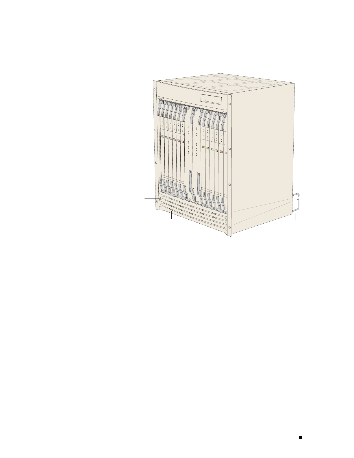
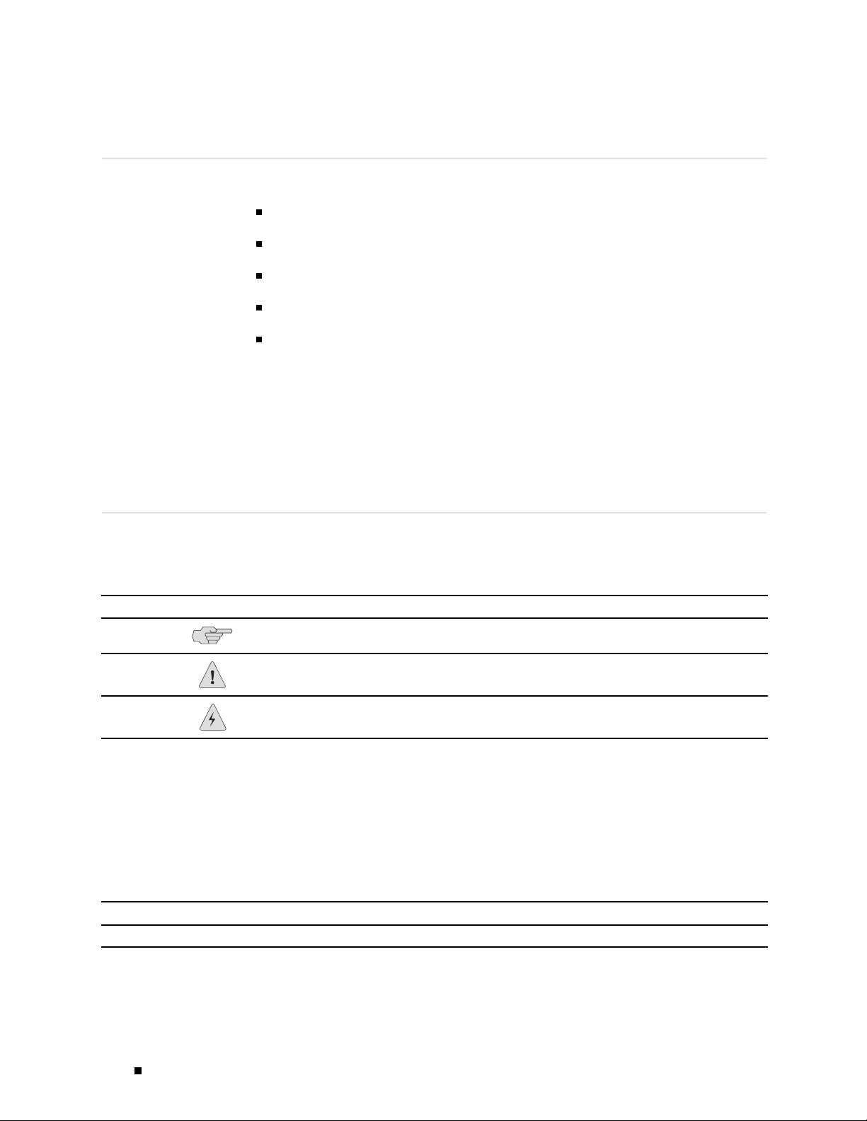
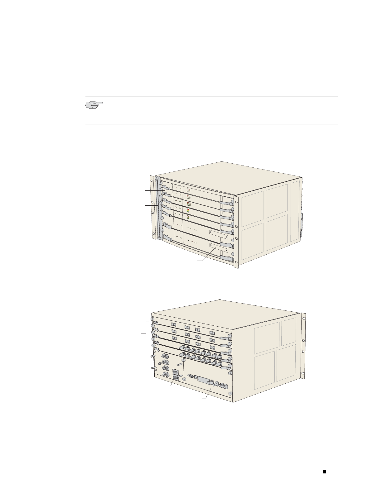
Figure 1: ERX-14xx Models, Front View
Fan tray
behind bezel
Line module
SRP module
PCMCIA slot
ERX Over view
Air filter (optional)
behind bezel
Bezel
g013727
Cable
management
bracket
ERX Routers 5
Page 24
ERX 8.0.x Hardware Guide
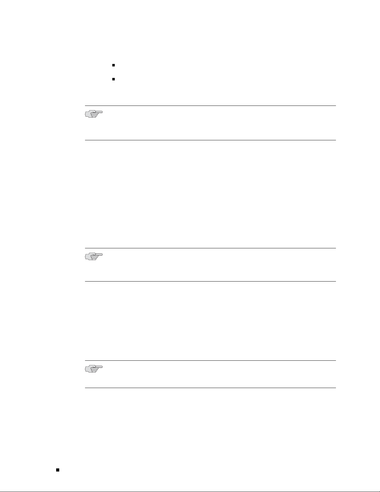
Figure 2: ERX-14xx Models, Rear View
I/O
module
SRP I/O
module
Power input
module
Fan tray
ERX-7xx
Models
Cable
management
bracket
Plenum
g013728
NOTE: In the E-series documentation, the term ERX-7xx models refers to both the
ERX-705
router and the ERX-710 router. The terms ERX-705 router and ERX-710
router refer to the specific models. See Figure 3 and Figure 4.
The ERX-
7xx models are robust, high-density routers with less capacity
than the ERX-14xx models. The ERX-7xx models use either the
SRP-10G module or the SRP-5G module.
YoucanconfiguretheERX-7xxmodelstoenablethelinemodules(LM)tooperate
at full line rate performance or at a rate dependent on the resources available.
either
For information abo ut configurin g performance of line modules, see JUNOSe
System Basics Configuration Guide, Chapter 6, M a na gin g Modules.
6 ERX R outer s
NOTE: Th
e 10-Gbps SRP module used in the ERX-310 router is different from the
10-Gbps SRP module used in the ERX-710 router. See “SRP Module” on page 10
for more information.
Page 25
ERX Over view
The ERX-705 chassis is the same as the ERX-710 chassis. (See Figure 3 and Figure 4.)
The chassis co
ntains seven slots to accom m odate modules. In stallation procedures
and operating procedures are identical for both systems. All ERX-7xx and ERX-14xx
models use the same SRP I/O module, but different power input modules are used.
NOTE: The rout
chapter, depending on the line modules in the slots.
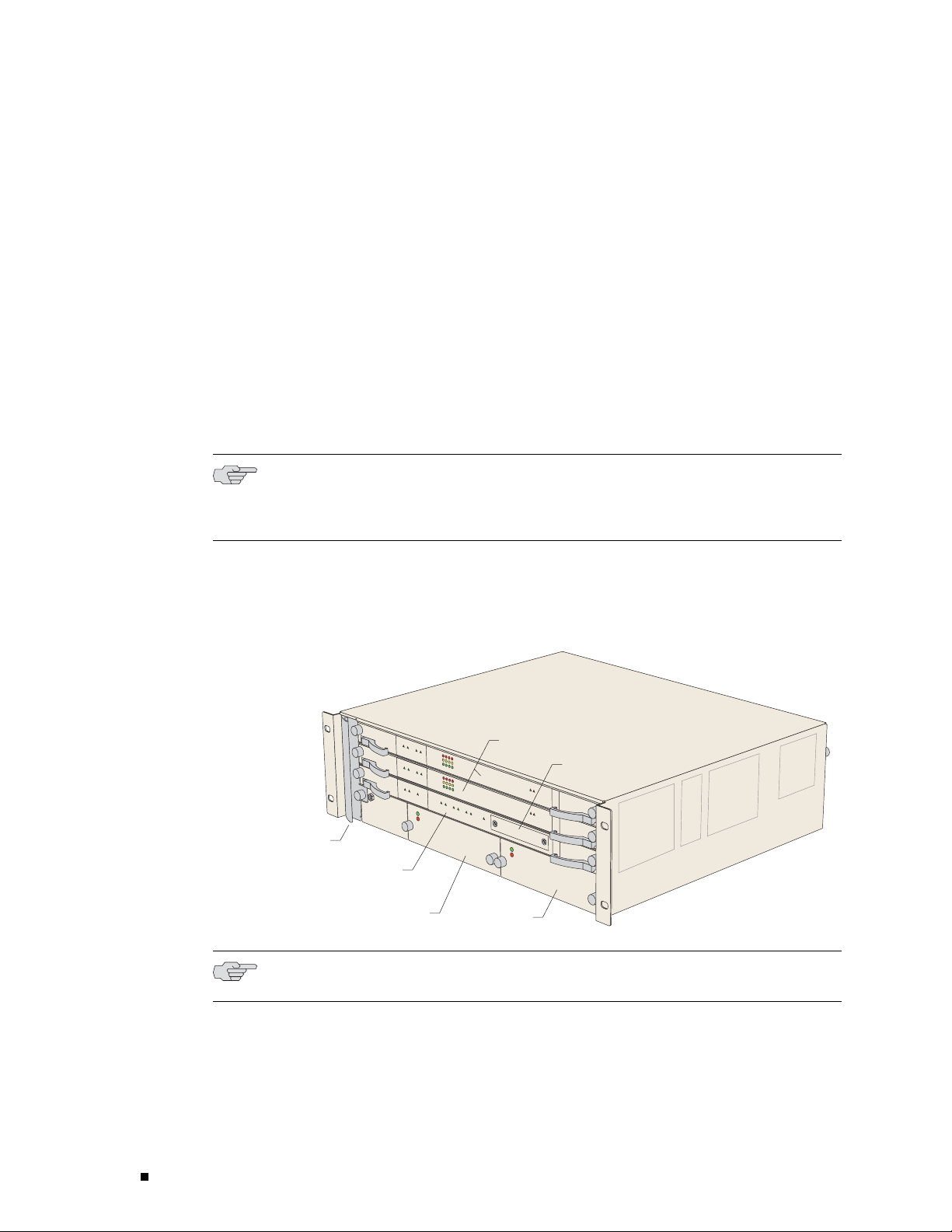
Figure 3: ERX-7xx Models, Front View
Line module
Fan tray
SRP module
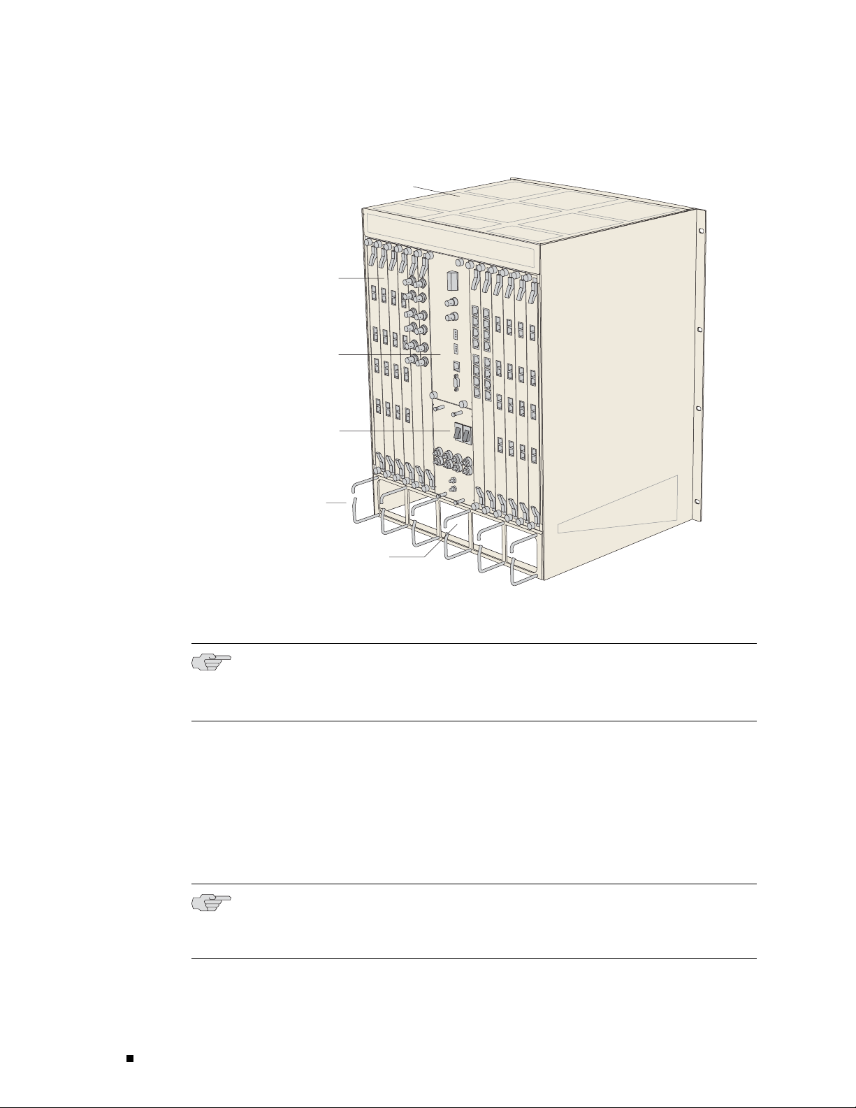
Figure 4: E
RX-7xx Models, Rear View
er may loo k different from the routers shown in the figures in this
PCMCIA slot
g013729
I/O
modules
Power input
module
Power switches
SRP I/O module
g013730
ERX Routers 7
Page 26
ERX 8.0.x Hardware Guide
ERX-310 Router
The ERX-310 router is a low-end platform that supports all of t he same services
as the ERX-7xx
and ERX-14xx models, but with smaller capacity and scaling
capabilities. Like the ERX-7xx and ERX-14xx models, the ERX-310 router
uses the s am e software architecture, providing a single IP entry point into
the network w
ith the same IP-based protocols and services that are available
on other ERX routers. The ERX-310 router is designed to be used as a small
distributed POP router as well as a high-end CPE router.
The ERX-310 router is a three-slot chassis with a midplane architecture. One slot
supports one
nonredundant 10-Gbps SRP module, while the other two slots support
line modules. The router supports existing E-series ASIC-based lin e modules (except
the OC48/STM16 line module), as well a s a select number of combination cards.
The combina
tion cards provide a fixed combination of interfaces on the I/O module
so that a single slot can suppo r t multiple interfaces (ATM OC3 and GE, for example).
NOTE: The 10-Gbps SRP module used in the ERX-310 router is different from
the 10-Gbps
SRP module used in the ERX-7xx and ERX-14xx models. See “SRP
Module” on page 10 for more information.
Figure 5: ER
The ERX-310
X-310 Router, Front View (AC Model)
Fan tray
NOTE: Th
router is available in either redundant AC- or DC-powered models.
SRP module
AC power
supply A
e DC model has blank filler panels in power supply slots.
Line modules
AC power
supply B
PCMCIA slot
g013731
8 ERX R outer s
Page 27
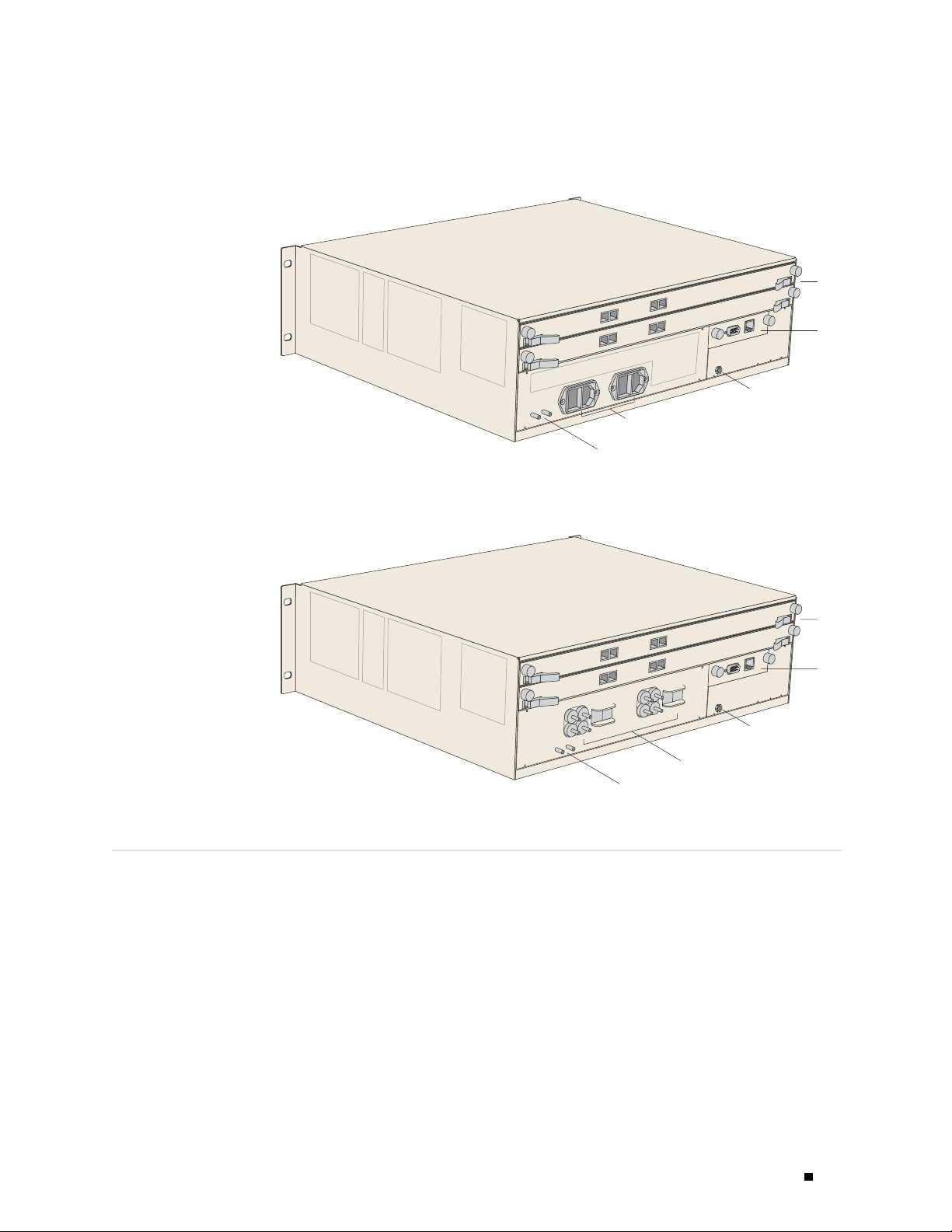
Figure 6: ERX-310 Router, Rear View (AC Model)
g013732
ERX Over view
I/O module
SRP I/O
module
ESD grounding jack
AC power inputs and
switches A and B
Grounding posts
Figure 7: E
ERX Mod
RX-310 Router, Rear View (DC Model)
g013733
ules
Each sy
use any line module for access or uplink . Access line modules receive traffic
from low-speed circuits, and the system routes the traffic onto higher-speed
uplin
stem supports an SRP mod ule and a se lection of line mod ules. You can
k line modules and then to the core of the network.
I/O
module
SRP I/O
module
ESD grounding jack
DC power inputs
and switches A and B
Grounding posts
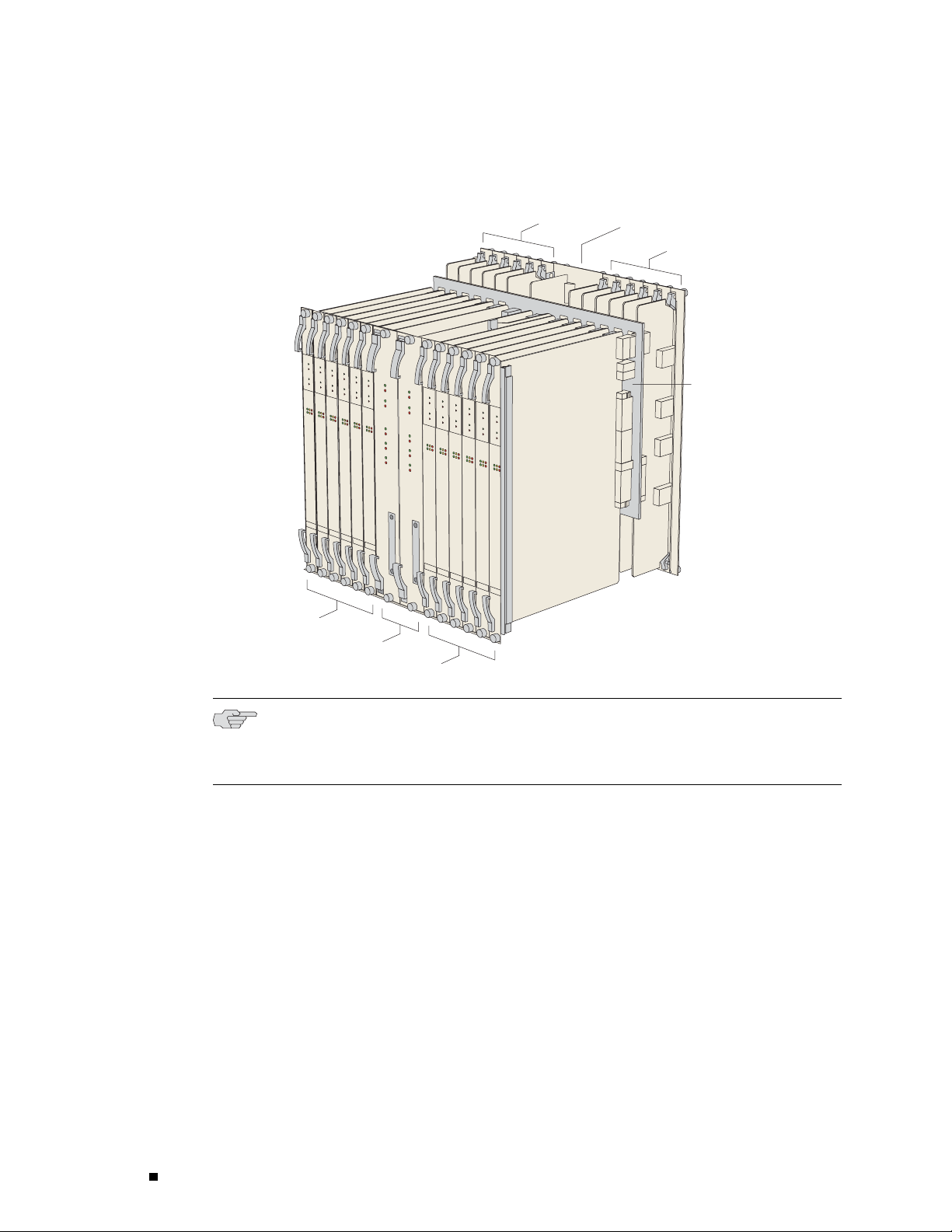
Each m
oduleconnectstoacorrespondingI/Omoduleviaapassive
midplane. See Figure 8.
The front panel of each module contains a collection of status LEDs
(light-emitting diodes). For information about how to interpret the
see “Troubleshooting” on page 103.
LEDs,
ERX Modules 9
Page 28
ERX 8.0.x Hardware Guide
Figure 8: Modules in ERX-14xx Models
Line modules
SRP modules
Line modules
I/O modules
SRP I/O
module
I/O modules
Connection via
passive midplane
g013734
SRP Module
NOTE: So
me line modules require a minimum amount of memory to be used
with JUNOSe Release 5.3.0 or a higher-numbered release. See the ERX Module
Guide for line module specifications.
Switch route processor (SRP) modules perform system management, routing
alculations and mainten an c e, forwarding table com pu tations, statistics
table c
processing, configuration storage, and other control plane functions. Each
SRP module is a PowerPC-based system with its own memory, no nvolatile
orage, and p ower supply. (See Figure 9 and Figure 10.)
disk st
10 ERX M odules
Page 29
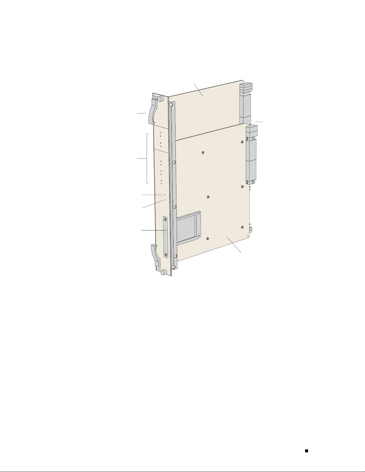
Figure 9: SRP Module for ERX-7xx and ERX-14xx Models
Fabric board
Ejector
Status LEDs
ERX Over view
Midplane
connectors
Board reset
button
NMI button
PCMCIA
NVS card
System
processor board
g013735
ERX Modules 11
Page 30
ERX 8.0.x Hardware Guide
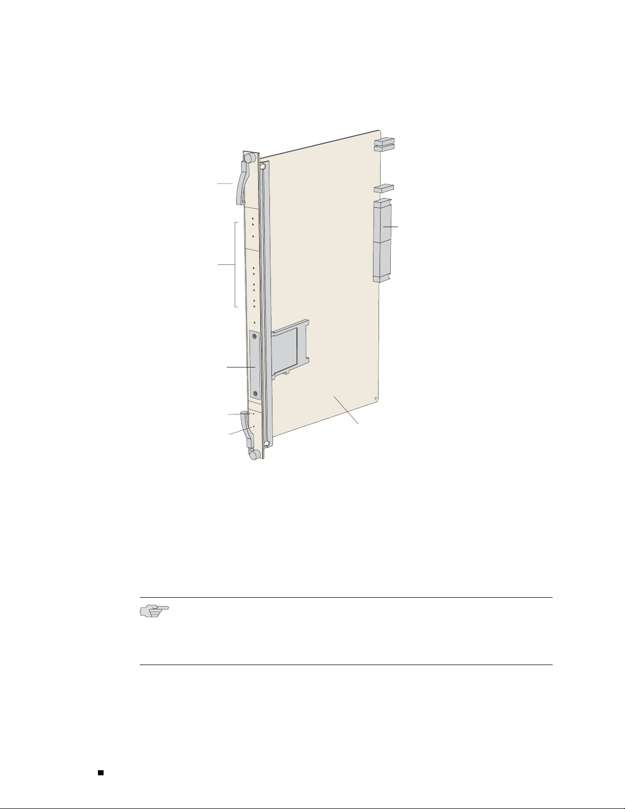
Figure 10: SRP Module for ERX-310 router
Ejector
Status
LEDs
g013736
Midplane
connectors
PCMCIA
NVS card
Board reset
button
NMI button
Integrated fabric system
processor board
Module Details
ERX-7xx and ERX-14xx models use up to two redundant SRP modules operating
in an ac
An SRP module must be present for any system to boot.
SRP modules ranging from 5 Gbps to 40 Gbps can be used in ERX-7xx and
ERX-14xx models. Only a 10-Gbps SRP module (SRP-SE10G) can be used in
ERX-3
NOTE: Because of different physical dimen s io ns and switch fabric capabilities, SRP
modules are not interchangeable between systems. For example, the 10-Gbps SRP
module
router, and vice versa.
tive/standby configuration. ERX-310 routers use o nly one SRP module.
10 routers. See the ERX Module Guide for complete information.
used in ERX-7xx and ERX-14xx models cannot be used in th e ERX-310
12 ERX M odules
Page 31

ERX Over view
CAUTION: Do not remove the SRP module while the system is running.
NOTE: Some SRP modules require a minimum amount of memory to be used
with JUNOSe Rel
Guide for module specifications.
ease 5.3.0 or a higher-numbered release. See the ERX Module
SRP I/O Module
For details abo
ut installing SRP modules, see “Installing Modules” on page 35.
SRP Module Redundancy
SRP module redundancy is available only for ERX-7xx and ERX-14xx models.
See “ Redund an
cy Features” on page 16 for more information.
Nonvolatile Storage
ThePCMCIAslotonthefrontoftheSRPmoduleholdsaTypeIIPCMCIAnonvolatile
storage (NVS)
system’s software and configuration files. The PCMCIA card is factory installed.
CAUTION: Alth
router, we recommend that you do not do so. If you remove the card while data is
being written to or copied from the NVS card, data can be lost or corrupted.
Therefore, we
a PCMCIA NVS card.
card. (See Figure 9 and Figure 10.) This card is loa de d with the
ough you can remove PCMCIA NVS (Flash) cards from a running
strongly recommend that you shut down the router before removing
The SRP I/O module is a single corresponding input/output module that interfaces
with the SRP m
works with all SRP modules, but is router specific. The I/O module used in
ERX-7xx a nd ERX-1 4 xx models canno t be used in the ERX-310 router, a nd
vice versa.
odules through the system’s m id plane. The same SRP I/O module
See Figure 2, Figure 4, and Figure 6 for locations.
Module Details
The SRP I/O module provides standard craft management interfaces, including:
10/100Base-T—The port enables access to the ERX router for Ethernet
management
functions via CLI or SNMP, for example.
ERX Modules 13
Page 32

ERX 8.0.x Hardware Guide
RS-232—The p ort provides a serial connection for monitoring the system’s
hardware conf
iguration through a PC (running terminal emulation software) or
ASCII terminal. Allows d irect CLI access.
Alarm contacts—The contacts provide for remote indication of critical, major,
and minor router alarms (ERX-7xx andERX-14xxmodelsonly;currently
not implemen
ted)
Line Modules
External tim
ing inputs—The inputs provide a method of ensuring that the
clock timin g used by the router remains synchronized with the network’s
system clock. BNC connectors and wire wraps are available for ERX-7xx
and ERX-14xx
For details a
bout installing the SRP I/O module, see “Installing Modules” on page 35.
models only.
Line modules (LM) process data from different types of network connections.
For informa
tion about available lin e modules and which SRP modules supp ort
specific line modules, see the ERX Module Guide.
Figure 11 shows a representative line module. For details about installing
line modules, see “Installing Modules” on page 35.
14 ERX M odules
Page 33

Figure 11: Representative Line Module
Ejector
ERX Over view
Status LEDs
Board reset
button
NMI button
Midplane
connectors
g013737
Packet Classification
Most line modules support packet classification on ingress; some non-ASIC line
module
fields (such as source an d destination IP address, source a nd destinatio n port,
and protocol), the ingress IP interface, layer 2 fields, or some combination
of the
s do not. A classification engine on the line module m a tches specific
se against user-configured filters at wire speed.
I/O Modules
Most line modules have a corresponding input/output (I/O) module that provides
ysical interconnection to th e network. Insert each I/O module into the
the ph
back of the system, directly be hin d its corresponding line module.
For information about which line modules pair w ith which I/O mod ules, see the
ERX Module Guide. See Figure 2, Figure 4, and Figure 6 for locations. For details
installing I/O modules, see “Installing Modules” on p age 35.
about
ERX Modules 15
Page 34

ERX 8.0.x Hardware Guide
Network Management Tools
You can use different management tools to configure the system to
meet the speci
CLI Management
The CLI provides fully developed a nd automated configuration and status
functionalit
network. For a full discussion of the CLI, see JUNOSe System Basics
Configuration Guide, Chapter 2, Command-Line Interface.
SNMP MIB Management
The system offers a complete SNMP interface for configuration, status,
and alarm reporting. The system supports both Standard and Enterprise
MIBs (Manage
Enterprise MIB is ASN.1 notated for easy importing into third-party SNMP
management applications. For more information, see JUNOSe System Basics
Configurat
ion Guide, Chapter 4, C onfiguring SNMP.
fic networking requirements.
y through a local RS-232 port, Telnet, or SSH via any reachable
ment Information Bases). The Juniper Networks E-series
NMC-RX Device Management System
The NMX-RX application provides a global method of managing all routers,
line modul
es, and ports through a graphical user interface.
Redundancy Features
This section describes system redundancy features.
SRP Modules
NOTE: This s
contain one SRP module and therefore do not offer SRP module redundancy.
ERX-7xx and
When two SRP modules of the same type are installed in the chassis, one acts as a
primary (active) and the second as a redundant (standby) module. Both SRP
modules sh
If the stan
(and high-availability mod e is not enabled), it reboots the system and takes
control. If high-availability mode has been enabled, automatic switchover
occurs wi
the software to the redundant SRP and reboot it. For information a bout
configuring and managing SRP module redundancy, see JUN O Se System
Basics Co
ection applies to ERX-7xx and ERX-14xx models only. ERX-310 routers
ERX-14xx models use a 1:1 redundancy scheme for the SRP module.
are a single SRP I/O module lo cated in the rear of the chassis.
dby SRP module detects that the primary SRP module is not active
th near hitless failover. If you upgrade software, you must copy
nfiguration Guide, Chapter 6 , Managing Modules .
16 Redundancy Features
Page 35

ERX Over view
After you install two SRP modules, the modules negotiate for the primary role.
Anumberoffac
preference is given to the module in the lower-numbered slot. The SRP modules
record their latest roles and retain them the next time you switch on the system.
For informati
tors determine which module becomes the primary; however,
on about installing SRP modules, see “Installing Modules” on page 35.
NVS Cards
If you have two SRP modules installed in a system, you can use NVS cards
of different
higher-capacity NVS card will equal that of the lower-capacity NVS card. For
information about installing NVS cards, see “Installing Modules” on page 35.
When you install new NVS cards or SRP modules, you must issue the synchronize
command to m
module with the file system of the NVS card on the primary SRP module.
(The NVS card on the redundant SRP module will hereafter be referred to
as the redun
hereafter be referred to as the primary NVS card.)
capacities on the SRP modules. The effective capacity of the
atchthefilesystemoftheNVScardontheredundantSRP
dant NVS card; the NVS card on the primary SRP module will
Line Modules
If the capacity of the primary NVS card is equal to or smaller than that o f the
redundant NVS card, the system copies all the files from the primary NVS card to the
redundant
of the redundant NVS card, the system creates an invisible synchronization reserve
file on the primary NVS card, provided that there is enough space for the file.
The purpose of the synchronization file is to prevent the creation of data that
cannot fi
is not visible when you view the files in NVS. The size of the fi le is e q ual
to the difference in capacities of the two NVS cards. For example, if the
primary N
a capacity of 220 MB, the size of the synchronization file is 4 MB, and only
220 MB of space is available on the primary NVS card.
If the prim ary NVS card does not have enough space to create the synchronization
reserve
on the console. To resolve this issue, either d elete unwanted files from the prim ar y
NVS card or replace the redundant NVS card with a higher-capacity NVS card.
NOTE: Th
do not offer line module redundancy.
NVS ca rd. However, if the capacity of the primary NVS card exceeds that
t on the redundant NVS card. The file contains no useful data, and
VS card has a capacity of 224 MB and the redundant NVS card h as
file, the synchronize command fails, and a warning message is displayed
is section applies to ERX-7xx and ERX-14xx models only. E R X-310 routers
ERX-7xx
line modules. For details about which line modules support redundancy,
see the ERX Module Guide. In this scheme, an extra line module in a group
and ERX-14xx models support line module redundancy for several
Redundancy Features 17
Page 36

ERX 8.0.x Hardware Guide
of identical line modules provides redundancy in case of line module
failure. To us
e this feature, you need a:
Spare line mod
Redundancy mi
Redundancy I/
Aredundancym
ule
dplane
O module
idplane can cover 3–6 slots. It provides additional connectivity that
enablesthesparelinemoduletotakecontroloftheI/Omoduleassociatedwith
any failed line module in the redundancy group. The spare I/O module provides
connectivit
The process b
y from the spare line module to the redundancy midplane.
y which the system switches to the spare line module is called
switchover. When switchover occurs, the system:
1. BreakstheconnectionbetweentheprimaryI/Omoduleandtheprimary
line module.
2. Connects the primary I/O module to the spare line module via the redundancy
midplane and redundancy I/O module.
Protocol processing then takes place on the spare line module.
Figure 12 shows the data flow when a spare line module becomes active.
18 Redundancy Features
Page 37

Figure 12: Data Flow When a Spare Line Module Is Active
Redundancy
I/O module
Primary
I/O module
Midplane
ERX Over view
g013738
Power
Redundancy
midplane
Spare line module
Primary line module
For information abou t installing modules for line module redundancy,
see “In
stalling Modules” on page 35. For information about configurin g
and managing SRP module redundancy, see JUNOSe System Basics
Configuration Guide, Chapter 6, Managing Modules.
All E-series routers provide a power architecture that distributes redundant –48 VDC
feeds through the router to each line module, SRP module, and fan module where
-DC converters provide local c onversion to the required secondary voltages.
DC-to
1. A packet arrives at the primary I/O module.
2. The packet passes along the redundancy
midplane from the primary I/O module to
the redundancy I/O module.
3. The packet passes from the redundancy
I/O module to the spare line module.
4. The spare line module processes the packet.
The ER
X-310 router is available with either DC or AC power inputs. The AC-powered
version can be configured with one or two hot-swappable power supplies for optional
redundancy. (See Figure 5 and Figure 6.) The power suppli es convert AC power to
rnal –48 V redundant DC feeds that are then distributed through the router.
inte
Redundancy Features 19
Page 38

ERX 8.0.x Hardware Guide
Fans
Forced air-cooling keeps the temperature of the E-series modules and components
within normal
operating limits. In ERX-14xx models, six cooling fans are located
in a tray at the top of the router (Figure 1). In ERX-7xx mo d els, four cooling fans
arelocatedinatrayononesideoftherouter(Figure3). IntheERX-310router,
two cooling f
ans are located in a tray on one side of the router (Figure 5).
The system mo
nitors the temperature of each module. If the temp erature of a
module exceeds the maximum limit, the system immediately goes into thermal
protection mode and the modules are powered off. The ERX system controller
enters a low p
ower mode, keeps the modules in a power-off condition, a nd does
not respond to any management interface commands. For information about
troubleshooting high operating temperatures, see “Troubleshooting” on page 103.
In ERX-7xx and ERX–14xx models, the fan tray has two redundant converters
that power t
he fans (for the ERX-14xx models, a –24 V, 50 W converter; for the
ERX-7xx m od el s, a –12 V, 15 W converter). If one converter fails, the other
takes over. The ERX-310 router does not have redundant converters.
For all E-series routers, the system software reports an alarm if any
of the fans
or con verters fail.
20 Redundancy Features
Page 39

Part 2
Initial Installation
Unpacking and Inspecting ERX Routers on page 23
Installing E
Installing Modules on page 35
Cabling ERX Routers on page 53
Powering Up E
Accessing ERX Routers on page 77
RX Routers on page 27
RX Routers o n page 73
Initial Installation 21
Page 40

22 Initial Installation
Page 41

Chapter 2
Unpacking an
This chapter reviews shipping contents and unpacking procedures for ERX routers.
It contains the following sections:
Before You Begin on page 23
Unpacking E
Unpacking ERX-7xx Models and ERX-310 Routers on page 24
Inspecting Router Components and Accessories on page 25
If You Detec
Contacting Junipe r Networks on page 25
The Next Step on page 25
Before You B
egin
Before you b
d Inspecting ERX Routers
RX-14xx Models on page 23
t or Suspect Damage on page 25
egin unpacking the router, be sure you have the following tools:
A N o. 2 Phill
A utility kn
Amechanica
Unpacking ERX-14xx Models
ERX-14xx models come boxed, bolted, and strapped to a skid. For
your conve
location where you want to install it.
WARNING: Th
system into position and one to screw it to the rack.
To u np ack E
ips screwdriver
ife
l lift, or at least two people to assist in lifting
nience, we recommend that you unpack the router in the
ree people are required to install the router in a rack: two to lift the
RX-14xx models:
Unpacking ERX-14xx Models 23
Page 42

ERX 8.0.x Hardware Guide
1. Cut the two straps that secure the carton to the skid, open the carton from the
top, and remov
2. Unlock the four plastic clips that hold the box to the skid by squeezing them in
their center a
3. Remove the three screws that attach each of the two L-brackets to the router.
4. To avoid scratching the router when removing it from the skid, detach one of
e the box of accessories that sits on top of the router.
nd pulling out, and then lift the carton off the router.
the L-brackets from the skid by removing the three screws. See Figure 13.
Figure 13: Re
moving an L-Bracket
L-bracket
g013739
Unpacking ERX-7xx Models and ERX-310 Routers
ERX-7xx models and ERX-310 routers are shipped boxed, but n ot attached
to a ski
router in the location where you want to install it.
To u npack an ERX-7xx model or an ERX-310 router:
1. Open the carton from the top.
2. Remove
3. Remove the router from the box.
24 Unpacking ERX-7xx Models and ERX-310 Routers
d. For your convenience, we recommend that you unpack the
the box of accessories that sits on top of the system.
Page 43

Unpacking and Inspecting ERX Routers
WARNING: Three people are required to install the router in a rack: two to lift the
system into pos
ition and one to screw it to the rack.
Inspecting Ro
uter Components and Accessories
After you remo
Confirm the co
Inspect all ex
damage.
Inspect all accessories ship pe d with each un it.
Document any damage noted during your inspection.
Confirm that the router has the correct number and type of modules for
your ordered configuration.
ve the equipment from the shipping containers:
If You Detect or Suspect Damage
If you detect or suspect damage to any equipment:
Contact the shipper responsible for delivery, and formally report the damage.
Contact your Juniper Ne tworks sales representative or reseller.
ntents of each container.
ternal surfaces and external connectors for visible signs of
Contacting J
uniper Networks
The Next Step
Please conta
or Mexico) or 408-745-9500 (from elsewhere), or contact your sales representative
if you have any questions or concerns. See “Contacting Customer Support and
Returning H
To familiarize yourself with the electrical, environmental, and other guid elines
and require
and Requirements” on page 129.
If you are familiar with these guidelines and requirements, turn to “Installing
ERX Routers” on page 27.
ct Juniper Networks at 1-888-314-JTAC (from the United States, Canada,
ardware” on page 151 for complete contact information.
ments for installing ERX routers, turn to “Installation Guidelines
The Next Step 25
Page 44

ERX 8.0.x Hardware Guide
26 The Next Step
Page 45

Chapter 3
Installing E
This chapter descri bes how to install ERX routers i n a rack. I t contains the following
sections:
Before You B
egin
Before inst
RX Router s
Before You Begin on page 27
Freestandi
Rack-Mounted Installation on page 28
The Next Step on page 33
Haveaplanf
expansion of your system.
Have the tools and accessories needed to complete the installation.
Read and u nderstand the clearance requirements for the front and back of
the chassis for cable routing and other unit access. See “Environmental
Requireme
ng Installation on page 27
alling E-series routers, be sure you:
or installing the routers that takes into consideration future
nts” on page 130 for more information.
Read and un
adequate ventilation.
Prepare the equipment racks by measuring and marking space for each
router and plenum you plan to install.
Freestanding Installation
When installing the system on a table top or in any other freestanding mo de,
be su re to leave enough space around the system for adequate ventilation.
Position
local communications, and remote communications.
See “Installation Guidelines and Requirements” on page 129, and “System
Specifications” on page 119, for more information.
derstand the clearance requirements for the chassis to ensure
the router with easy access to the connections that it ne eds for power,
Freestanding Installation 27
Page 46

ERX 8.0.x Hardware Guide
WARNING: Two people are required to lift an E-series router.
CAUTION: To p re
sure persons handling the router wear an antistatic device.
Connectors are
modules are installed from the rear of the router. (See Figure 14.) See “Cabling
ERX Routers” on page 53 for cabling installation procedures.
Figure 14: ERX-7xx Models, Rear View
I/O
modules
Power input
module
Power switches
vent electrostatic damage to the system and its components, make
located on the I/O modules and the power input module. These
SRP I/O module
g013730
Rack-Moun
ted Installation
We recomme
Rack Requirements” on page 133 for detailed rack information.
Installa
tion Guidelines
Before in
guidelines and refer to Figure 15:
28 Rack-Mounted Installation
nd that you use a standard EIA distribution rack. See “Equipm e n t
stallingthesystemsinarack,considerthefollowing
You can in stall up to 3 ERX-14xx m o d els, 6 ERX-7xx models, or 14 ERX-310
routers in a single 7-ft. (2.1 m) rack.
Installing multiple systems in a single rack enables you to maximize your
availabl
espace.
Page 47

Installing ERX Routers
You can install an ERX-14xx m odel, an ERX-7xx model, and an ERX-310
router togeth
er in the sa me rack. (Se e Figure 15.)
CAUTION: If you install an ERX-7xx model or ERX-310 router directly above an
ERX-14xx mode
l in the same rack, you must install a plenum between the ERX-7xx
model or ERX-310 router and the ERX-14xx model so that the air can circulate
between the systems. (See Figure 51.) This plenu m is available from Jun iper
Networks.
If you install
an ERX-14xx model above an ERX-7xx model or ERX-310 router,
thereisnoneedtoinstallaplenumbetweentheunitsbecausetheERX-7xx
models and ERX-310 routers vent air out the side of the chassis.
Install heavier systems, such as an ERX-14xx model, on the bo ttom of the
rack. Mount l
ighter systems, such as the ERX-310 router, higher in the rack.
Rack-Mounted Installation 29
Page 48

ERX 8.0.x Hardware Guide
Figure 15: ERX Routers Installed in Recommended Order
Safety Guidelines
Observe the following safety guidelines when mounting the router in a rack.
WARNING: Install equipment in the rack from the bottom upward. This helps to
maintain the stability of the rack and reduces the chance of the rack tipping over.
WARNIN
system into position and one to screw it to the rack.
30 Rack-Mounted Installation
G: Three people are required to install the router in a rack: two to lift the
Page 49

Installing ERX Routers
CAUTION: Evaluate the overall loading of the branch circuit before you install
any equipment i
nto a rack.
WARNING: Connect the router or rack to ground (earth), and ensure that a reliable
grounding path is m aintained in the rack.
WARNING: Do not
work on the system or connect or disconnect cables during
lightning activity.
WARNING: Be sure circuit breakers for the power source are in the OFF position
before attachi
ng power cables.
WARNING: Before servicing the router, t urn off the power.
WARNING: Remove jewelry (including rings, necklaces, a nd watches) before
working on equi
pment that is connected to power lines. Metal objects heat up
when connected to power and g round and can cause serious burns or become
welded to the terminals.
WARNING: Do not insert any metal object, such as a screwdriver, into an open slot
or the back plane. Doing so c an cause elec tric shock and serious burns.
WARNING: The ER
X-310 router AC model has more than one power-supply cord.
Disconnect two power cords before servicing to avoid electric shock.
Rack-Mounted Installation 31
Page 50

ERX 8.0.x Hardware Guide
Preparing the Equipment Racks
Following your installation plan, use a tape measure and m arking pen to mea sure
and mark space
spacing, follow Network Equipment Building System (NEBS) requirements. If you
choose not to install a plenum, be sure to include 2 U of space between each
chassis for p
Installing the Router
To compl ete the i nstallation of the router in a rack, you need:
A Phillips screwdriver
Depending on th e router, up to eight 10-32 x 3/8 Phillips screws (provided with
the router) f
on each equipment rack for each router component. For horizontal
roper exhaust. A plenum, however, is highly recommended.
or each router to be installed
WARNING: Thr
ee people are required to install the router in a rack: two to lift the
system into position and one to screw it to the rack.
CAUTION: Make sure all persons handling a router wear an antistatic device.
To install the router in the rack:
1. With one person standing on the left side of the router and another standing
on the right side, lift the router into the rack.
2. Position the router in its designated location in the equipment rack. Make
sure the holes of the mounting brackets align evenly with the holes of the
equipment ra
3. Starting at the b o ttom, have the third person secure the router in the
equipment r
4. Connect the necessary cables. (See “Cabling ERX Routers” on page 53 for
instructio
ck on both sides.
ack by using the 10-32 x 3/8 Phillips screws.
ns on installing the cables.)
Figure 15 illustrates a distribution rack with one ERX-310 router, one
ERX-7xx mod
el, and one ERX-14xx model installed.
32 Rack-Mounted Installation
Page 51

The Next Step
Installing ERX Routers
After you finish installing the router:
If you need to install any modules, see “Installing Modules” on page 35.
If the router was delivered with the modules already installed, see “Cabling
ERX Routers” o
n page 53 for instructions on connecting cables.
The Next Step 33
Page 52

ERX 8.0.x Hardware Guide
34 The Next Step
Page 53

Chapter 4
Installing M
This chapter describes how to install and remove E-series modules. For information
about managing installed modules, see JUNOSe System Basics Configuration Guide,
Chapter 6, M
This chapte
odules
anaging Modules.
r contains the following sections:
Overview on page 35
Safety Guidelines on page 40
Installing
Installing Line and I/O Modules on page 44
Removing a Line Module, SRP Module, or SRP I/O Module on page 46
Installing
Configuring Line Modul e Redundancy on page 51
The Next Step on page 51
SRP I/O and SRP Modules on page 41
Components for Line Module Redundancy on page 48
Overview
Line modul
I/O module slots are located in the rear. See “ERX Overview” on page 3
for front and rear views of ERX routers.
In ERX-14xx models, modules mount vertically in a chassis with 14 slots.
In ERX-7xx
chassis with 7 slots and 3 slots, respectively. See Figure 16.
e slots are located in the front of each ERX chassis, while
models and ERX-310 routers, modules mount horizontally in a
Overview 35
Page 54

ERX 8.0.x Hardware Guide
Figure 16: Orientation of Line Modules in ERX Routers
ERX-7xx model
Slot Groups
ERX-14xx model
ERX-310 router
For details about available line modules and compatibility between line
modules and SRP modules, see the ERX Module Guide .
The slots in the ERX-1410 router a nd ERX-7xx models are divided into groups. The
number of groups and number of slots per group depend on the system.
There are no slot groups in the ERX-1440 router or the ER X-310 router.
In the ER
X-310 router, slot 0 contains the SRP module and slots 1
and 2 each contain a line module.
Slot Gro
Aslotgr
ups for the ERX-1410 Router
oup in the ERX-1410 router com prises three adjacent chassis slots. The
groups for the ERX-1410 router consist of the following slots (Figure 17):
Slotgroup1—Slots0through2
Slotgroup2—Slots3through5
g013742
36 Overview
Slot group 3—Slots 8 through 10
Slot group 4—Slots 11 through 13
Slots 6 and 7 are reserved for the SRP modules.
Page 55

Figure 17: ERX-1410 Slot Groups
12340 5 6 7 8 9 10 11 12 13
Chassis slots
SRP SRP
CT3 OC3CT1 OC3CT1CT1 CT3 CT3 CT3
Installing Modules
Figure 1
Slot
group 1
Slot
group 2
Slot Groups for the ERX-7xx Models
A slot group in an ERX-7xx model comprises one slot or two adjacent slots. The
groups fo
Slots 0 an
8: ERX-7xx Model Slot Groups
Chassis slots
r an ERX-7xx model consist of the following slots ( Fig ure 18):
Slot grou
Slot gro
Slot gro
Slot grou
d 1 are reserved for the SRP modules.
6
5
4
3
2
1
Slot
group 3
p1—Slots2and3
up 2—Slot 4
up 3—Slot 5
p4—Slot6
Slot
group 4
g013743
OC3CE1 CE1
E3 ATM
Slot group 4
Slot group 3
Slot group 2
Slot group 1
0
SRP SRP
g013744
Overview 37
Page 56

ERX 8.0.x Hardware Guide
Combinations of Line Modules In Slot Groups
For informati on about combinations of lin e modules in slot groups, see JUNOSe
System Basics
Configuration Guide, Chapter 6, Managing Modules.
OC48 Line Modules
The ERX-1440 router with t he SR P- 40 G+ SRP m odule supports OC48 line
modules. Othe
r ERX routers do not support OC48 line modules.
An OC48 line mo
install this line module only in slots 2–3 and slots 4–5. Other slots in
the system do not support this line module.
The corresponding OC48 Frame APS I/O module spans only one slot. Install the I/O
module in the
dule spans two slots in an ERX-1440 router. You can
lower of the slots (either slot 2 or slot 4) that the line module spans.
GE-2 Line Modules
The ERX-1440 router with the SRP-40G+ SRP module supports GE-2 line
modules in a
module is in slot 2 or s lot 4 . The line module can be used with other SRP
modules, but maximum line performance w ill not be achieved.
The ERX-310 router with the SRP-SE10G SRP module supports GE-2 line m o du les in
both slots (
Other ERX ro
ll slots; however, full bandwidth is delivered only when the line
1 and 2). Maximum line performance is achieved in either slot.
uters do not support GE-2 line modules.
Managing Modules Using the Software
For information about software procedures associated with replacing
and managi
Guide, Chapter 6, Managing Modules.
ng modules, see JUNOSe System Basics Configuration
Hot-Swapp
Protectin
38 Overview
ing Modules
g Modules and Slots
All ERX rou
toaddorremoveamodulewithoutpoweringdownthesystem.
Each ERX ch
Table 4 for locations. To prevent damage from electrostatic discharge, connect
an antistatic wrist strap to the jack when handling components.
ters support hot-swapping of modules. Hot-swapping enables you
assis h as an ESD (electrostatic discharge) grounding jack. See
Page 57

Figure 19: Connecting the Wrist Strap to the ERX-310 Router (Rear)
ESD grounding jack
Installing Modules
Antistatic
wrist strap
g013745
Table 4: Grounding Jack Locations
E-series Router Location
ERX-14xx models Front: inside front bezel in lower-left corner
ERX-7xx models Rear: lower-right corner
ERX-310 router
To protect the modules and slots when installing modules, observe
the following guid elines:
CAUTION: When handling modules, use an antistatic wrist strap connected to the
router’s ESD grounding jack. This action helps to protect the module from damage
by electrostatic discharge.
CAUTION: Always handle the module by its edges. Do not touch the components,
pins, leads, or solder conn ections.
Rear: upper-right corner
Front: lower-left corner
Rear: lower-right corner
Overview 39
Page 58

ERX 8.0.x Hardware Guide
CAUTION: If you meet strong resistance w hen attempting to seat the module using
the ejectors, r
the module. Then verify, if applicab le, that the module matches its corresponding
module (I/O module or line module). Also, be sure that you have aligned the top
and bottom edg
CAUTION: Be su re to cover every empty slot with a blank filler panel to protect the
system from dust or o ther foreign substances and to ensure proper system cooling.
emove it from the chassis and confirm that the slot is designed to hold
es in the correct matching tracks.
CAUTION: Do no
in an antistatic bag.
Order of Installation
Before you attempt to install or replace a line mo du le (inserted in the front of
the cha ssis), make sure t he corresponding I/O module (inserted in the rear of
the chassis)
is installed in a chassis slot. If the c orresponding I/O module is not present, the
diagnostics fail, and you need to remove and reinsert the module.
is already in place. The slot diagnostics run when a line module
Required Tools and Safety Items
Youneedthefollowingtoolstoinstallalinemodule:
A Phillips screwdriver
An ESD wrist strap
Safety Guid
elines
Before and d
uring the installation process, observe the following precautions:
t discard the antistatic bag. When a module is not in use, store it
40 Safety Guidelines
WARNING: Do not work on the system or connect or disconnect cables d uring
lightning ac
tivity.
Page 59

Installing Modules
WARNING: Be sure circuit breakers for the power source are in the OFF position
before attachi
ng power cables.
WARNING: Remove jewelry (including rings, necklaces, a nd watches) before
working on equipment that is connected to power lines. Metal objects heat up
when connected
to power and ground and can cause serious burns or become
welded to the terminals.
WARNING: Do not
insert any metal object, such as a screwdriver, into an open slot
or the back plane. Doing so c an cause elec tric shock and serious burns.
WARNING: Never attempt to repair parts of modules yourself. Only trained
customer serv
ice personnel are authorized to service parts. Call Ju niper Networks
Customer Service to make arrangements to return defective modules for repair.
Installing SRP I/O and SRP Modules
You must install SRP mod ules in specific slots in each router. See
Table 5 for SRP module slot assignments.
Table 5: SRP Module Slot Assignments
Router Slot
ERX-14xx models 6 and 7
ERX-7xx mode
ERX-310 router 0
ls
0and1
NOTE: Because of different physical dimen s io ns and switch fabric capabilities, SRP
modules are not interchangeable between systems. For example, the 10-Gbps SRP
module used in ERX-7xx and ERX-14xx m odels cannot be used in an ERX-310
router, and vice versa.
Installing SRP I/O and SRP Modules 41
Page 60

ERX 8.0.x Hardware Guide
NOTE: Install the SRP I/O module before you install the SRP module; otherwise, the
system diagnostics will fail.
Installing an SRP I/O Module
To install an SRP I/O module:
1. Ground yourself by using an antistatic w rist strap or other device and connect
it to the ESD gr
2. With a Philli ps screwdriver, loosen the captive screws that secure the blank filler
panel coverin
3. Remove the SRP I/O modu le from its antistatic bag, being careful not to touch
module compo
ounding jack on the chassis.
g the empty chassis slot, if present, and remove the filler panel.
nents, pins, leads, or solder c onnections.
Installing a
4. Slide the module into the ch assis by placing it between the guides of the
NOTE: See the figures in “ERX Overview” on page 3 for module locations.
5. Tighten the module’s captive screws u sing a Phillips screwdriver. Turn both
n SRP Module
To instal l an
1. Ground yours
NOTE: See the
2. Choose the slot in which you want to install the module.
selected slo
t and pushing the mo du le until it stops.
screws several times before tightening them completely to allow the module
to sit correc
tly.
SRP module:
elf by using a n antistatic wrist strap or other device and connect
it to the ESD grounding jack on the chassis.
figures in “ERX Overview” on page 3 for module locations.
ERX-14xx models—Slot 6 or 7
ERX-7xx models—Slot 0 or 1
ERX-310 router—Slot 0
42 Installing SRP I/O and SRP Modules
Page 61

Installing Modules
3. With a Philli ps screwdriver, loosen the captive screws that secure the blank filler
panel coverin
4. Remove the SRP module from its antistatic bag, being careful not to touch
module compon
5. Verify that the ejectors are in the open position, as shown in Fig ure 20.
g the empty chassis slot, if present, and remove the filler panel.
ents, pins, leads, or solder connections.
Figure 20: Eje
ctors in the Open Position
Opened
Closed
Closed
Opened
g013746
6. Slide the module into the ch assis by placing it between the guides of the
ted slot and pushing the module until it stops.
selec
The module s tops sliding when the ejectors make contact with the front
chassis.
of the
CAUTION: If you meet strong resistance w hen attempting to seat the module using
the ejectors, remove it from the chassis and confirm that the slot is designed to hold
the mo
dule. Then verify, if applicable, that the module m atches its corresponding
Installing SRP I/O and SRP Modules 43
Page 62

ERX 8.0.x Hardware Guide
module (I/O module or line module). Also, be sure that you have aligned the top
and bottom edg
7. Insert the module into the backplane by simultaneously depressing both
ejectors (as s
8. Tighten the module’s captive screws using a Phillips screwdriver. Alternately
turn each scre
themoduletositcorrectly.
Installing Line and I/O Modules
This section describes the procedures for installing line and I/O modules.
NOTE: Install the I/O mo dule before you install the corresponding line m odule;
otherwise, t
when you issue the show version command. If this occurs, remove and reinsert
the line module.
he diagnostics fail and the line module’s status is listed as inactive
es in the correct matching tracks.
hown in Figure 20) and exerting forward pressure on the module.
w several times before tightening them co m pletely to allow
Installing a
Line Module or an I/O Module
To insta ll a m
1. Ground yours
it to the ESD grounding jack on the chassis.
2. Choose the s
NOTE: Line modules are in the front of the system and I/O modules are in the
back of the sy
odule:
elf by using a n antistatic wrist strap or other device and connect
lotwhereyouwanttoinsertthemodule.
stem.
44 Installing Line and I/O Modules
Page 63

Table 6: Module Slot A ssignments
Router Module Slot
ERX-1440 router
ERX-1410 router
ERX-7xx models Install modules in slots 2–6
ERX-310 router
3. With a Phillips screwdriver, loosen the screws that secure the blank filler panel
covering the empty chassis slot, if present, and remove the filler panel.
Install modules other than the OC48
modules in slots 0–5 and slots 8–13
Install the OC48 line module in slots
2–3 and slots 4–5
Install the corresponding I/O module
only in the lower of the two slots
(either slot 2 or slot 4) that the line
module spans
Install modu
Install modules in slots 1–2
les in slots 0–5 and slots 8–13
Installing Modules
4. Remove the module from its antistatic bag, being careful not to touch module
components, pins, leads, or solder connections.
5. Verify that the ejectors are in the open position, as shown in Fig ure 20.
6. Guide the module into the chassis by placing it between the guides of the
selected slot and pushing the module until it stops.
The module s tops sliding when the ejectors make contact with the front
of the chassis.
CAUTION: If you meet strong resistance w hen attempting to seat the module using
the ejectors, remove it from the chassis and confirm that the slot is designed to hold
the module. Then verify, if applicab le, that the module matches its corresponding
module (I/O module or line module). Also, be sure that you have aligned the top
and bottom edges in the correct matching tracks.
7. Insert th e module into the midplane by simultaneously depressing both
ejectors (as shown in Figure 20) and exerting forward pressure on the module.
8. Tighten the module’s captive screws using a Phillips screwdriver. Alternately
turn each screw several times before tightening them co m pletely to allow
themoduletositcorrectly.
Installing Line and I/ O Modules 45
Page 64

ERX 8.0.x Hardware Guide
Removing a Line M odule, SRP Module, or SRP I/O Module
NOTE: We recommend that you issue the slot disable command from the CLI
beforeremovingalinemoduleorI/Omodule.
CAUTION: If you
do not use the halt command before removing or powering down
an SRP, the system’s NVS card can become corrupted.
To remove a l ine
1. For SRP modules
module, SRP module, or SRP I/O module:
and SRP I/O modules, issue the appropriate halt comma nd
(halt, halt primary-srp,orhalt standby-srp).
See JUNOSe Syst
em Basics Configuration Guide, Chapter 6, Managing Modules for
information about the halt commands.
2. Ground yourse
lf by using an antistatic wrist strap or other device and connect
it to the ESD grounding jack on the chassis.
3. Useascrewdri
ver to loosen the thumb screws located at the top and bottom of
the module panel.
4. Pull the eject
or handles located at the top and bottom of the module so that
they are in position 2, as shown in Figure 21.
46 Removing a Line Module, SRP Module, or SRP I/O Module
Page 65

Figure 21: Ejectors in the Closed Position
Opened
Closed
Installing Modules
Closed
Opened
5. Carefully slide the module out of the chassis.
6. Place t
he mod ul e in its antistatic bag, being careful not to touch module
g013747
components, pins, leads, or solder connections.
7. Cover t
he empty chassis slot with a blank filler panel, and tighten the filler
panel’s captive screws using a Phillips screwdriver. Turn both screws several
times before tightening them completely.
If you remove an I/O module and not the corresponding line module, the line module
reboots. Its status becomes inactive when you issue the show version command.
If you remove a line mo dule and do not delete the corresponding
guration, the status of the lin e module is listed as n ot present
confi
when you issue the show version command.
Removing a Line Module, SRP Module, or SRP I/O Module 47
Page 66

ERX 8.0.x Hardware Guide
Installing Components for Line Module Redundancy
A spare line module provides redundancy for a group of identical line
modules for ER
NOTE: The ERX-310 router does not support line module redundancy.
X-7xx and ERX-14xx models only.
For line module
The line module
The redundancy
The I/O modules
For more inform
WARNING: Do not insert any metal object, such as a screwdriver, or place your hand
into an open slo
rings, necklaces, and watches) before working on equipment that is connected to
power lines. These actions can prevent electric shock and serious burns.
CAUTION: When h
router’s ESD grounding jack, and hold modules by their edges. Do not touch the
components, pins, leads, or solder connections. These actions help to protect
modules from d
redundancy to operate, you must install:
s,includingthesparelinemodule
midplane
, including the spare I/O module
ation, see “Redundancy Features” on page 16.
t or the backplane when the router is on. Remove jewelry (including
andling modules, use an antistatic wrist strap connected to the
amage by electrostatic discharge.
Installing th
eLineModules
To install the
1. Install the sp
group.
2. Install the o
I/O Modu les” on page 44.)
line modules in a redundancy group:
are line m odule in the lowest-numbered slot of the redundancy
ther line modules in the remaining slots. (Se e “Installing Line and
Installing the Redundancy Midplane
To install the redundancy midplane in a redundancy group:
48 Installing Components for Line Module Redundancy
Page 67

Installing Modules
CAUTION: Ifyoudonotusethehalt command before removing or powering down
an SRP, the syst
1. Enter the halt command.
em’s NVS card can become corrupted.
See JUNOSe System Basics Configuration Guide, Chapter 6, Managing Modules for
information about the halt command.
WARNING: Turn
off the router before you install the redundancy midplane. Working
inside the router when it is on can lead to electric sho ck and serious burns.
2. Turn off the power switches located on the power input mod ule in the rear
of the system (Figure 22).
3. Remove the I/O modules from the slots that the redundancy midplane will
span.
4. Place the redundancy midplane in the chassis so that it rests again st the guides
below the chassis midplane (Figure 22).
5. Align the screw ho les in the redundancy midplane with the screw holes in the
guides so that the m idplane covers the slots for the redundancy group.
6. Using a Phillips screwdriver and the screws provided, loosely attach, but do not
tighten, the redundancy midplane to the guides.
7. Carefully insert an I/O module in one slot to ensure that the redundancy
midplane is aligned correctly; then tighten the screws.
CAUTION: A misaligned redundancy midplane can result in bent pins on the
backplane an
d midplane and poor contact between the I /O modules and the
redundancy m idplane.
Installing Components for Line Module Redundancy 49
Page 68

ERX 8.0.x Hardware Guide
Figure 22: Installing a Redundancy Midplane
Install
Redundancy
midplane
ing the I/O Modules
To ins ta
1. Install
redundancy group.
CAUTION: When setting up a redundancy group with line modules, be sure to install
the redundancy I/O module in the lowest-numbered slot of the redundancy group.
It is po
can damage other I/O modules connected to the redunda ncy midplane.
2. Instal
redundancy group. (See “Installing a Line Module or an I/O Module” on
page 44.)
3. Cable each module to provide a path to the remote interface. (See “Cabling
ERX Routers” on page 53.)
g013748
ll the I/O mo d ules in a redundancy group:
the redundancy I/O module in the lowest-numbered slot of the
ssible to install the redundancy I/O module in other slots; however, doing so
l the corresponding I/ O module for the line module of each slot in the
50 Installing Components for Line Module Redundancy
Page 69

Verifying the Installation
To verify that the installation is complete:
1. After you have cabled the system for power, as described in “Cabling ERX
Routers” on pa
The system reboots.
2. Issue the show redundancy command, and verify that t he display shows
the redundancy hardware.
ge 53, turn on the power switches.
Configuring Line Module Redundancy
For information about configuring line modu le redundancy, see JUNOSe System
Basics Confi
guration Guide, Chapter 6, Managing Modules.
Installing Modules
The Next Step
After you install the modules, you can connect cable s to the system.
See “Cabling
ERX Routers” on page 53.
The Next Step 51
Page 70

ERX 8.0.x Hardware Guide
52 The Next Step
Page 71

Chapter 5
Cabling ERX R
This chapter describes how to cable an ERX router. Before you cable the router,
ensure that you have completed all installation instructions identified in previous
chapters.
This chapte
Cabling Overview on page 53
Required Tools, Wires, and Cables on page 55
Cabling the
Cabling the Router for Power on page 60
Cabling I/O Modules on page 66
The Next Ste
Cabling Overview
Cabling an ERX router requires the following main tasks:
outers
r contains the following sections:
SRP I/O Module on page 56
p on page 72
1. Familiarize yourself with the mo dule ports, and ensure that you have the cables
and wires n
2. Read and understand all safety warnings. (See “Installation Guidelines and
Requireme
3. (Optional) Connect timing ports.
4. Connect the SRP I/O module to the network and to a manage m en t console.
5. Connect gr
6. Connect the power cables from the power source to the power input module.
7. Connect the line I/O modules to their appropriate n etwork interface.
eeded to complete each cabling procedure. (See Figu re 23.)
nts” on page 129.)
ounding wires to the router chassis.
Cabling Overview 53
Page 72

ERX 8.0.x Hardware Guide
NOTE: We recommend that you use shielded cables w here appropriate.
Figure 23: ERX Ports and Connectors (ERX-14xx Model Shown)
OC3-4
I/O module
(slot 12)
I/O module
(slot 9)
Port 0
CT3
RX
TX
Alarm leads
External timing ports (Europe)
External timing ports (North America)
OC3
OC3-4
I/O
I/O
SINGLE
MODE
OC3-4
I/O
SINGLE
MODE
CT3
I/O
SRP I/O module
(slot positions 6 and 7)
FE-8 I/O module
(slot 5)
CT3
I/O
ALARMSEXTERNAL TIMINGCONSOLE
MINOR
MAJOR
CRITICAL
E1 75 OHM
CLOCK IN
+
-
+
-
+
-
FE-8
I/O
Port 0
Port 1
Port 2
ATG
T1 100 OHM
CLOCK IN
10/100
BASE T
RS-232
BTG
R
R
Port 3
10/100 BASE T port
RS-232 terminal port
OC3
I/O module
(slot 13)
Port 1
RX
TX
Blank
faceplate
Ejector
54 Cabling Over view
THIS PRODUCT IS EQUIPPED WITH
TWO POWER FEEDS. DISCONNECT
BOTH FEEDS PRIOR TO SERVICE.
POWER A POWER B
-48VDC -48VDCRTN RTN
-48VDC RTN -48VDC RTN
!
POWER A POWER B
WARNING!
NO OPERATOR ACCESSIBLE
COMPONENTS. AUTHORIZED
SERVICE PERSONNEL ONLY.
|
ON
O
OFF
Power input module
|
ON
O
OFF
Power A and Power B
on/off switches
Power A and Power B
input connectors
Ground terminals
g013749
Page 73

Required Tools, Wires, and Cables
Cabling your system takes only a few minutes. You need the following
items and thos
e listed in Table 7 for proper installation:
Cabling ERX Routers
1/8–inch flat
3/8–inch wren
No. 2 Phillips
Ground wires—
#10 (ERX-7xx a
head screwdriver
ch or 3/8–inch nut-driver
screwdriver
We recommend a minimum of 10-AWG ground wire.
nd ERX-14xx models) or #8 (ERX-310 router) kep nut to
connect the ground (earth) wire to the ground terminal.
Power input module wiring— We recommend a minimum of 8-AWG wire for
ERX-14xx models, 12-AWG wire for ERX-7xx models, and 14-AWG wire for
ERX-310 rout
ers (DC model) with a dual stud terminal lug with 5/8–inch
spacing. For the ERX-310 router AC model, use a standard IEC power cord.
Consider the distance from the connection point and the configuration of the
system when determining the size of wire used.
See “System Specifications” on page 119 for more information on router
specificat
Table 7: Req
Connection Port and Cable Used
Management connection between SRP I/O module and the
LAN
Management connection between SRP I/O module and a
managemen
Direct connections to I/O modules See the ERX Module Guide for specific I/O module connector
uired Cables
tconsole
ions.
One 10/100Base-T Ethernet management port with an RJ-45
connector
OneRS-232portwithaDB-9connectorforVT100
managemen
information
t access
NOTE: If you plan to use a cable-management bracket (ERX-7xx and ERX-14xx
models only), install it before you begin cabling your router. Cable-management
brackets are h elpful to keep network interface cables untangled and orderly
and to prevent cables from hindering access to other slots. See “Installing a
Cable-Management Bracket on ERX-7xx Models” on page 100.
Required Tools, Wires, and Cables 55
Page 74

ERX 8.0.x Hardware Guide
Cabling the SRP I/O Module
Before powering up the router, you must set up a management console. The
console enabl
and to manage your system using the command-line interface (CLI).
When connecting a console directly to the SRP I/O module, use a cable appropriate
foryourterminalconnector.ThecablemusthaveafemaleDB-9connectortoattach
to the RS-232
es you to communicate with your system during the power-up process
port on the SRP I/O module. See Figure 24 an d Figure 25.
Table 8: SRP I/O Ports
The console p
ort is conside red a data terminal e quip m en t interface
(DTE). Direct connection to a terminal or PC (which also have DTE
interfaces) requires a crossover cable.
NOTE: The alar
m function on the SRP I/O module is currently not implemented.
Only ERX-7xx and ERX-14xx models have external timing ports and alarm leads
located o n th
e SRP I/O m odule. All ERX routers have console ports located on
the SRP I/O mod ule. See Tab le 8 for details on ea c h component.
Port Description
Alarm leads (ERX-7xx and ERX-14xx models
only)
External timing ports (ERX-7xx and ERX-14xx
models only)
Management console ports One 10/100Base-T Ethernet
Six terminal blocks for external alarm
contacts; use a minimum 26-AWG for each
(currently not implemented)
Two 3-pin wire-wrap posts for US
external clock sources; primary (A)
and seconda
Two BNC connectors for E1 clock
sources; pr
management port with an RJ-45
connector
ry (B)
imary (A) and secondary (B)
External Timing Ports
NOTE: This section applies to ERX-7xx and ERX-14xx models only. The ERX-310
router does not support external timing.
56 Cabling the SRP I/O Module
One RS-232 console port with a DB-9
connector for VT100 management
access
Page 75

Cabling ERX Routers
The SRP I/O module has two input ports for external clock sources.
These ports pr
ovide a way to ensure that the router system clock remains
synchronized with the network’s system clock. The primary clock is labeled
A; the secondary, redundant cloc k is labeled B.
Use the connectors appropriate for your locale (European or
North Americ
an standard):
European—Tw
North Americ
o 75-ohm E1 2.048-Mbps inputs with BNC connectors
an—Two 100-ohm T1 inputs with three pin wire-wrap
connectors. Pins are labeled T (tip), G (ground) , and R (ring). We recommend
using 26-AWG wire minimum.
NOTE: Use shi
elded cables to connect the external clock sources to the clock
source input ports.
Cabling the SRP I/O Module 57
Page 76

ERX 8.0.x Hardware Guide
Figure 24: SRP I/O Module for ERX-14xx Models
BNC (Europe)
Wire-wrap connectors
(North America, Japan)
RJ-45
26-AWG wire
ALARMSEXTERNAL TIMING
CONSOLE
MINOR
MAJOR
CRITICAL
E1 75 OHM
CLOCK IN
T1 100 OHM
CLOCK IN
10/100
BASE T
RS-232
+
-
+
-
+
-
ATG
BTG
R
R
DB-9
To co n
1. Depen
58 Cabling the SRP I/O Module
nect the clock source input ports:
ding on the connector type, complete one of the following tasks:
E1: Attach the BNC co nnector to Clock A’s external timing port.
T1: Wrap the tip wire on pin marked T of Clock A’s external timing port,
round wire on G pin, and the ring wire on R pin.
the g
g013750
Page 77

Management Ports
Cabling ERX Routers
NOTE: You can use a wire-wrap gun to attach wires to pins.
2. Attach the opposite end of the external timing cable or wires to your network’s
clock source A
3. Repeat Steps 1 and 2 for the Clock B connections.
.
NOTE: This section applies to all ERX routers.
The C onsole section of the SRP I/O module has two ports for management
access. (See Figure 24 and Figure 25.)
Figure 25: SR
The 10/100Base-T Ethernet port accepts an RJ-45 (male) connector, providing
an out-of-ban
The RS-232 por
d connection for LAN access through a Telnet session or SNMP.
t accepts a DB-9 (female) connector for direct CLI access
from a console terminal.
The console port is considered a da ta terminal equipment interface (DTE).
Direct connection to a terminal or PC (which also have DTE interfaces) requires
a c rossover c
P I/O Module for the ERX-310 Router
SRP I/O module
RS-232 10/100
able.
BASE T
g013751
See “Accessing ERX Routers” on page 77 for more information
about m anage ment access.
Cabling the SRP I/O Module 59
Page 78

ERX 8.0.x Hardware Guide
Connecting to the Network
To connect the router to the network:
1. Insert an Ethernet cable (RJ-45) connector into the 10/100Base-T (RJ-45) port
on the SRP I/O m
2. Connect the o ther end of the cable to the appropriate Ethernet network for
an ou t-of-ban
odule un til it clicks into place.
dconnection.
Connecting t
When you conn
appropriate for your terminal connector. The cable must have a female DB-9
connector to attach to the RS-232 port on the SRP I/O module.
To connect the console to the SRP I/O module:
1. InsertthefemaleDB-9connectorintotheRS-232port,andtightenthescrews.
2. Connect the other end of the cable to your terminal’s serial port (VT100/ANSI).
Cabling the Router for Power
After you have correctly cabled the modules and I/O modules, you
must attach grounding and electrical wires before you attempt system
power-up. T
1. Switch all r
CAUTION: Sw
installation.
o a Console Terminal
ect a console directly to the router SRP I/O module, use a c able
hree main tasks are involved:
outer power switches to OFF.
itches may have inadvertently flipped to ON du ri ng shipping and
2. Connect the grounding wires to the chassis.
WARNING: Always connect the grounding wires first (before connecting the power
cables) and disconnect them last when installing or servicing the router.
3. Connect the power cables (AC o r DC) to the power input module s.
See “System
routers. Table 9 identifies the power input module cab ling requirements, an d
Figure 26 shows the m ain comp onents o f a power i np ut module.
60 Cabling the Router for Power
Specifications” on page 119 for the power requirements for E RX
Page 79

Table 9: Power Input Module Cables and Wires Needed
Cable/Wire From To
ERX-14xx models
One 10-AWG ground wire Power input module ground terminal Termination ground
Two 8-AWG wire leads Power input module Power A –48 VDC
Appropriate leads on power source No.1
and RTN leads
Two 8-AWG wire leads Power input module Power B –48 VDC
Appropriate leads on power source No.2
and RTN leads
ERX-7xx models
One 10-AWG ground wire Power input module ground terminal Termination ground
Two 12-AWG wire leads Power input module Power A –48 VDC
Appropriate leads on power source No.1
and RTN leads
Two 1 2 - AWG w
ire leads
Power input
module Power B –48 VDC
Appropriat
e leads on power source No.2
and RTN leads
ERX-310 router
One 10-AWG ground wire Power input module ground terminal Termination ground
Two 14-AWG wire leads (DC model only) Power input module Power A –48 VDC
Appropriate leads on power source No.1
and RTN leads
Two 14-AWG wire leads (DC model only) Power input module Power B –48 VDC
Appropriate leads on power source No.2
and RTN leads
One AC power cord (AC model only) Power input module AC power IEC
receptacl
e
Appropriate AC power supply
Cabling ERX Routers
Cabling the Router for Power 61
Page 80

ERX 8.0.x Hardware Guide
|
ON
O
OFF
|
ON
O
OFF
WITH
POWER A POWER
POWER B
-48VDCTN RTN
|
ON
O
OFF
|
ON
O
OFF
POWER A POWER B
POWER B
-48VDC RTN
-48VDC RTN
O
OFF
PO
-48VDC
-48VDC
Figure 26: Power Input Module for ERX-14xx Models
THIS PRODUCT IS EQUIPPED WITH
TWO POWER FEEDS. DISCONNECT
BOTH FEEDS PRIOR TO SERVICE.
POWER A POWER B
Power B
leads
ON
O
OFF
|
Power input
module cover
g013752
|
ON
O
OFF
POWER A POWER B
-48VDC -48VDCRTN RTN
-48VDC RTN -48VDC RTN
WARNING!
NO OPERATOR ACCESSIBLE
COMPONENTS. AUTHORIZED
!
SERVICE PERSONNEL ONLY.
Power A
leads
Ground
Tas k
62 Cabling the Router for Power
1: Turn Off All Router Power
re starting, you must switch all router power switches to OFF.
Befo
rn off the router, push each power switch to the OFF position.
To tu
Page 81

Task 2: Connect the Grounding Cables
All ERX routers have two grounding studs located in the rear of the chassis, near
the power inpu
ts. Each stud provides grounding for a single power unit.
Cabling ERX Routers
To g rou nd ea ch
1. Locate the gro
2. Remove the nuts and locking washers from the grounding studs.
power unit:
unding studs on the router (Figure 26 and Figure 27).
NOTE: We recommend a minimum of 10-AWG ground wire with a ring style
terminal.
3. Place the grounding cable lead on one of the grounding studs and tighten
the nuts to sec
4. Connect the other end of the ground cable to the appropriate ground
termination l
5. Repeat Steps 3–4 for the remaining grounding stud.
ure the connection.
ead.
NOTE: When grounding an ERX router, leave a service loop in the grounding cable
to ensure that the grounding cable is the last cable to disconnect from the shelf if
strain is plac
ed on the electrical cables.
Task 3: Conne
ct the Power Cables
To connect po
Figure 26, Figure 27, and Figure 28 as needed.
wer cables to the router, follow these steps. Refer to
ERX-7xx Mode
WARNING: Before you begin t his procedure, ensure that all power switches are
in the OFF position.
1. Be sure you have completed Task 1 and Task 2 in the previous sections.
2. If applicabl
and remove it.
ls, ERX-14xx M odels, ERX-310 Router (DC Model)
e, loosen the screws from the clear power input module cover
Cabling the Router for Power 63
Page 82

ERX 8.0.x Hardware Guide
WARNING: Be sure the power source is turned off, the router is turned off, and
proper groundi
ng wires are attached before continuing with this procedure.
WARNING: The wiri ng color code of the power cab les depe nds on the color
coding of the DC power source installed at your site. Color code standards for DC
wiring do not ex
ist. To ensure that the correct polarity is connected to the router
power units, confirm the connection of the power cables to t he + (positive) and
– (negative) leads at the power source.
3. Removethenutsandlockingwashersfromthepostsforthepowerinput(A
or B) using a small insulated adjustable wrench.
4. Place one neg ative (neutral) cable lead on the post labeled –48 VDC.
5. Replace the lo
cking washers and nuts, and tighten the nuts to secure the
connection.
6. Place the othe
7. Replace the locking washer and nut, and tighten the nut to secure the
r cable lead on the post labeled RTN.
connection.
8. Attach the opposite end of Power A’s wire leads to the appropriate leads on
your power so
urce.
NOTE: To provide redundancy, do not term inate Power A and Power B leads at the
same power so
9. Place the clear plastic guard over the terminal posts, and se cure it in place by
tightening t
10. Repeat Steps 1–9 for each power input module in your configuration.
urce.
he four screws.
64 Cabling the Router for Power
Page 83

Figure 27: ERX-310 Router, Rear View (DC Model)
Cabling ERX Routers
Power A
leads
ERX-310 Ro
1. Insert the
DC power
input A
Ground
-48VDC RTN
OFF
O
Power A
POWER A
ON
|
switch
uter (AC Model)
power cord into the AC power IEC receptacle. (See Figure 28.)
DC power
input B
-48VDC RTN
OFF
O
Power B
switch
POWER B
ON
|
2. Insert the other end of the power cord into an appropriate AC power source.
NOTE: To provide redundancy, do not term inate Power A and Power B leads at the
same power source.
g013753
3. Repeat Steps 1–2 for the other power input module, if needed.
Figure 28: ERX-310 Router, Rear View (AC model)
O
|
POWER A POWER B
AC power input A
with switch
Ground
100-240V ~ 5A
50/60 Hz
AC power input B
O
|
with switch
g013754
Cabling the Router for Power 65
Page 84

ERX 8.0.x Hardware Guide
Cabling I/O Modules
This section illustrates the common conn ector types used with ERX
I/O modules. F
line modules, see the ERX Module Guide.
or information about the connectors on the different
BNC Connector
Figure 29: I/O
Module with BNCs
s
CT3
I/O
RX
TX
RX
TX
Port 0
Port 1
g013755
HSSI Connectors
66 Cabling I/O Modules
The HSSI I/O module uses a standard 50-pin HSSI connector.
CAUTION:
Do not terminate HSSI connections with SCSI connectors. Although
SCSI connectors lo ok very simila r to HSSI connectors, using SCSI connectors o n
HSSI connections can lead to data loss.
Page 85

Figure 30: HSSI I/O Module with 50-Pin HSSI Connector
HSSI-3
I/O
Cabling ERX Routers
Port 0
RJ-45 Connectors
When inserting an RJ-45 conne ctor, be su re it clicks into the port.
Figure 31: I/O Module with RJ-45 Connector
C Connectors
RJ-48
10/100
FE-2
I/O
g013756
Port 0
g013757
When i
nserting an RJ-48C connector, be sure it cl icks into the port.
Cabling I/O Modules 67
Page 86

ERX 8.0.x Hardware Guide
Figure 32: I/O Module with RJ-48C Connectors
CE1
I/O
Port 0
g013758
LC Duplex C
onnectors
In accorda
Class, Requirements, and User’s Guide (2001), multimode I/O modules
with LC connectors are defined as follows:
CLASS 1 LED PRODUCT.
In accordance with EN60825-1, Safety of Laser Products - Part 1: Equipment
Class, Re
with LC connectors are defined as follows:
CLASS 1 LASER PRODUCT.
WARNING: Do not look directly into LC-style fiber connectors. The fiber-optic laser
used in single-mode fiber (S M F) meets the regulatory requirements for casual
exposure
WARNING: IEC 825, Class 1 laser fiber connectors are for connection only to
Class 1 laser devices.
nce with EN60825-1, Safety of Laser Products - Part 1: Equipme nt
quirements, a n d User’s Guide (2001), single-mode I/O modules
to the eye; however, looking directly into a laser can cause eye damage.
SC Duplex
68 Cabling I/O Modules
Connectors
In accord
ance with EN60825-1, Safety of Laser Products - Part 1: Equipment
Class, Requirements, and User’s Guide (2001), multimode I/O modules
with SC connectors a re defined as follows:
Page 87

Cabling ERX Routers
CLASS 1 LED PRODUCT.
In accordance with EN60825-1, Safety of Laser Products - Part 1: Equipment
Class, Requir
ements, and User’s Guide (2001), single-mode I/O modules
with SC connectors a re defined as follows:
CLASS 1 LASER PRODUCT.
WARNING: Do not look directly into SC-style fiber connectors. The fiber-optic laser
used in single-mode fiber (S M F) meets the regulatory requirements for casual
exposure to th
e eye; however, looking directly into a laser can cause eye damage.
WARNING: IEC 825, Class 1 laser fiber connectors are for connection only to
Class 1 laser devices.
SC duplex connectors have the same basic shape as LC duplex connectors,
but are slight
ly larger. See Figure 33.
Cabling I/O Modules 69
Page 88

ERX 8.0.x Hardware Guide
Figure 33: I/O Module with SC Full D uplex Connectors
TX
RX
RX
TX
OC3
I/O
Port 0
SMB Connectors
Port 1
g013759
To cable I/O modules with SMB connectors, pull back the metal sheath on the
connec
tor, insert the connector into the selected port, and release the metal sheath.
70 Cabling I/O Modules
Page 89

Figure 34: I/O Module with SMB Connectors
CT3/T3
12
I/O
Cabling ERX Routers
Port 0
g013760
X.21/V.35 Connectors
Four cables are available for the X.21/V.35 I/O modules:
Each 200-pin proprietary socket on the I/O module provides connections to 8
V.35 or X.21 ports. The remote en d of th e cable is terminated with either 8 X.21
connecto
module determines whether the connection is X.21 or V.35 and DC E or DTE.
X.21DCEcable(terminatedwith8femaleX.21connectors)
X.21DTEcable(terminatedwith8maleX.21connectors)
V.35 DCE cable (terminated with 8 female V.35 connectors)
V.35 DTE cable (terminated with 8 male V.35 connectors)
rs or 8 V.35 connectors. The cable you attach to the port on the I/O
Cabling I/O Modules 71
Page 90

ERX 8.0.x Hardware Guide
Figure 35: X.21/V.35 Module with 50-Pin X.21/V.35 Connector
X.21/V.35
I/O
Port 0
Redundant Ports
The Next Step
g013761
Some modules have redundant ports. See the ERX Module Guide for specifications.
Cabling
both ports provides a redundant path to the module.
CAUTION: For port redundancy to operate correctly on a GE I/O module that
supports
SFPs, both the primary and redundant ports on an E-series GE I/O module
must use the same type of SFP.
See “Powering Up ERX Routers” on p age 73.
72 The Next Step
Page 91

Chapter 6
Powering Up E
This chapter describes how to power up an ERX router and determine whether it
has booted p roperly. It contains the following sections:
Before You Power Up the System o n page 73
Powering Up
Status LEDs on page 75
Powering Down on page 75
The Next Ste
RX Routers
Before You Power Up the System
Before powering up the system, make sure you complete the following tasks. See
the appropr
WARNING: Be sure the power source is turned off and the system is turned off
before you p
iate chapters in th is guide for information about these tasks.
erform the installation tasks.
on page 73
p on page 75
Powering Up
“Installing SRP I/O and SRP Modules” on pa ge 41
“Installing Line and I/O Modules” on page 44
“Cabling the SRP I/O Module” on page 56
“Cabling the Router for Power” on page 60
“Cabling I/O Modules” on page 66
For specifications on the electrical requirements for the system, see “System
Specifications” on page 119. For details on the power consumed by the
different
ERX modules, see the ERX Module Guide.
Powering Up 73
Page 92

ERX 8.0.x Hardware Guide
NOTE: In this procedure, we assume that the system is already connected to a
power source. See “Cabling ERX Routers” on page 53.
CAUTION: Evalu
ate the overall loading of the branch circuit before you install
any equipment in to a rack.
To power up the s
1. Verify that the
2. Inspect all grounding and power connections to the router chassis.
3. Confirm that all connections are secure.
4. Switch the powe
5. Monitor the LEDs on the front of the SRP modules to verify that the system
is booting pro
ystem:
power source is operational and turned on.
rswitchestoON.
perly. S ee Table 12 in “Troubleshooting” on page 103 for LED
status explanations.
When the promp
t appears on the system console, the system is in User Exec
mode and is ready to be configured:
host1>
6. Enter the enable command to access Privileged Exec mode:
host1>enable
host1#
Initializat
74 Powering Up
ion Sequence
In Privileged Exec mode you can begin to configure the system. See JUNOSe
System Basics Configuration Guide, Chapter 2, Command-Line Interface for
more informa
Each line mod
tion.
ule is initialized independe ntly. As a result, the CLI on the SRP
module can become available before the line modules have completed initialization.
Commands relating to a line module might fail if the module has not completed
initializa
tion. You can use the show version command to display line module
status. Do not enter commands for a line module until its state is listed as online.
Page 93

Status LEDs
Powering Up ERX Routers
Upon initial power-up, the components of the router run boot code, go through
a series of sel
f diagnostic tests, and synchronize with each other.
Powering Down
The Next Step
When the tes ts
status of the router. Observe the line module and SRP module L EDs in the front,
and the I/O line module and SRP I/O module LEDs in the rear.
See “Troubleshooting” on pa g e 103 for information on the system’s LEDs.
If you need to power down or remove the SRP module, first enter the halt
command to temporarily suspend the system’s operation. See JUNO Se System
Basics Confi
CAUTION: Ifyoudonotusethehalt command before removing or powering down
an SRP module
If you shut down the system improperly, it runs an investigation of the
file allocat
If you have problems powering up the system, see “Troubleshooting”
on page 103 for h
are complete, use the LEDs on each module to determine the
guration Guid e, Chapter 5, Managing the System for more information.
, the system’s NVS card might become corrupted.
ion table (FAT) the next time it reboots.
elp.
If the syste
m boots properly, see “Accessing ERX Routers” on page 77.
The Next Step 75
Page 94

ERX 8.0.x Hardware Guide
76 The Next Step
Page 95

Chapter 7
Accessing ER
This chapter discusses how to access the system to manage it. Managing your
router includes both configuring and monitoring it. For basic information on
the managem
Chapter 5, Managing the System.
This chapter contains the following sections:
X Router s
ent of the system, see JUNOSe System Basics Configuration Guide,
Setting Up M
Console Port Setup on page 78
Telne t Set up on p age 80
SNMP on page
The Next Step on page 82
Setting Up Management Access
Before you power up the system, you must set up a management console.
(See “Connecting to a Console Terminal” on page 60.) You use the console to
communica
andmanagethesystemusingthecommand-lineinterface(CLI).
te with the system during the power-up process, set an IP address,
anagement Access on page 77
82
You can manage and monitor the router through either of these methods:
Console terminal—Connect a console (PC, Macintosh, or UNIX workstation)
directly to the system’s RS-232 serial port.
Remote console—Connect the 10/100Base-T port on the S RP I/O module to an
Ethernet
For initi
directly to the system’s RS-232 port. Through this co n ne c tio n you can use the
CLI to set an IP address on the system. After you configure the IP address,
you can ac
network, and run Telnet from a remote console.
al access to the system, you need to physically connect your console
cess the system remotely (for example, via Telnet).
Setting Up Management Access 77
Page 96

ERX 8.0.x Hardware Guide
Console Port Setup
Using HyperTerminal
You can connect a console terminal (PC, Macin tosh, or UNIX workstation) directly
to the SRP I/O m
odule via the RS-232 terminal port. When you connect a console
directly to the system, you can configure the system without an IP address.
To communicate with the system, you must have a terminal emulation program
running on your PC or Macintosh. You can use any terminal emulation program,
such as Hyper
Terminal. A UNIX workstation can use the emulator TIP.
If your console uses a version of Microsoft Windows (such as Windows 95
or Windows NT
4.0) that supports the HyperTerminal application, you
can access the system via HyperTerminal.
1. Click the Start b utton and select Programs, Accessories, and HyperTerminal.
Connecting
2. In the Hyper
3. In the Connection Description window, enter a name for your router (for
example, er
4. Select any icon to represent your terminal emulation, and click OK.
5. In the Con nect To dialog box, in the C onnect using field, select the appropriate
COM port to use (for example, COM1), and click OK.
6. In the COM1 Properties window, select th e following settings:
Bits per sec
Data bits: 8
Parity: Non
Stop bits: 1
Flow contro
7. Click OK.
Directly to the Router
Terminal window, select HyperTerminal.
x1400)intheNamefield.
ond: 9600
e
l: Xon/Xoff
78 Console Port Setup
When you co
nnectaconsoledirectlytothesystem,useacableappropriate
for your terminal connector. The cable must have a f emale D B-9 conn ector
to attach to the RS-232 port on the system.
The console port is considered a data terminal equipment interface
(DTE). Dir
ect connection to a terminal or PC (which also have DTE
interfaces) requires a crossover cable.
Page 97

To connect a console directly to the system:
1. ConnectthefemaleDB-9connectortotheRS-232portonthesystem’sSRP
I/O module. Se
Figure 36: Management Ports for ERX Routers
eFigure36.
Accessing ERX Routers
2. Connect the crossover adapter connector to your PC’s serial port.
3. Power up
the system.
When you power up the system, the CLI appears on your console’s screen.
The syst
em is now in User Exec mode, and you can be gin configuration. For
more information on using the CLI and configuring the system, see the JUNOSe
System Basics Configuration Guide.
NOTE: Direct access through the RS-232 serial port enables you to monitor the
system while it boots.
Console Port Setup 79
Page 98

ERX 8.0.x Hardware Guide
Assigning an IP Address
When your console is ready to communicate with the system, power up the system.
(See “Powerin
system. The system powers up in User Exec mode. To assign an IP address:
1. Enter the enable command at the User Exec prompt.
g Up ERX Routers” on page 73.) Then set an IP address for the
host1>enable
host1#
The system is now in Privileged Exec mode.
Telnet Setup
2. SetanIPaddre
ss on the Ethernet interface:
Substitute the slot number where the SRP module is located for the
slotnumber va
riable. For redundant SRP modules, specify the lowest slot
number of the two (for example 0/0 or 6/0 ).
UseanIPaddressvalidforthesystem.
host1#configure terminal
Enter configuration commands, one per line. End with CNTL/Z.
host1(config)#interface FastEthernet slotnumber /0
host1(config-if)#ip address 10.10.7.3 255.255.255.0
3. Continue to configure the system’s parameters as needed.
After you have assigned an IP address to the system, you ca n communicate remotely
by running Telnet over an Ethernet network. See “Telnet Setup” on page 80.
After you have configured an IP address for the system, you can run
Telnet from a host to access the system through its Ethernet port. To
connect the
1. Connect an E
Ethernet port to the network:
thernet cable (RJ-45) to the system’s 10/100Base-T (RJ-45) port on
the SRP I/O module.
80 Telnet Setup
2. Connect the
other end of the cable to the appropriate Ethernet network for
an ou t-of-band connection.
Before you c
an access the system with Telnet, you must either configure a password
for Telnet ac cess or disable the password requirement from the management
console. In the following example, you disab le the password.
1. Enter the enable command.
host1>ena
host1#
ble
The system is now in Privileged Exec mode.
Page 99

2. Enter the configure command.
Accessing ERX Routers
host1#config
Enter configur
host1(config)
ure terminal
ation commands, one per line. End w ith CNTL/Z.
#
The system is now in Global Configuration mode.
3. Enter the line command.
host1(config)#line vty 0 4
host1(config-line)#
The system is now in Line Configuration m ode.
4. Disable the pa
host1(config-line)#no login
ssword.
NOTE: In this example, you disabled the password requirement, but you can choose
to set a password instead. See JUNOSe System Basics Configuration Guide, Chapter 8,
Passwords and Security for information on setting a password.
5. Run Telnet from a host on the same Ethernet network as the system.
6. Enter the IP address of the system to open the Telnet session.
TheUserExecpromptappearswhentheTelnetsessiontothesystemis
established.
host1>
7. Enter the enable command.
host1>enable
host1#
The system is now in Privileged Exec mode.
8. Enter the configure command.
host1#configure terminal
Enter configuration commands, one per line. End with CNTL/Z.
host1(config)#
The system is now in Global Configuration mode, from which you can
configure the system. S ee JUNOSe System Basics Configuration Guide, Chapter 2,
Command-Line Interface.
Telnet Setup 81
Page 100

ERX 8.0.x Hardware Guide
SNMP
CAUTION: D o not change the IP address for the Ethernet interface that you are
using to commun
Telnet session.
The system supports Simple Network Manageme nt Protocol (SNMP),
astandardma
the system as an SNMP agent.
As an SNMP agent, the system provides access to management information
that it m aintains. See JUNOSe System Basics Configuration Guide, Chapter 4,
Configuring
Guide A to M and JUNOSe Command Reference Guide N to Z for the commands
that are available for configuring the system as an SNMP agent.
icate with the system. If you change the address, you will lose the
nagement protocol for IP networks. You can configu re
SNMP for information on SNMP. See JUNOSe Command Reference
The Next Step
See “Maintaining ERX Routers” on page 85.
82 The Next Step
 Loading...