

Page 1

CSE2000
Hardware Installation Guide
Published: 2015-03-23
Copyright © 2015, Juniper Networks, Inc.
Page 2

Juniper Networks, Inc.
1133 Innovation Way
Sunnyvale, California 94089
USA
408-745-2000
www.juniper.net
Juniper Networks, Junos, Steel-Belted Radius, NetScreen, and ScreenOS are registered trademarks of Juniper Networks, Inc. in the United
States and other countries. The Juniper Networks Logo, the Junos logo, and JunosE are trademarks of Juniper Networks, Inc. All other
trademarks, service marks, registered trademarks, or registered service marks are the property of their respective owners.
Juniper Networks assumes no responsibility for any inaccuracies in this document. Juniper Networks reserves the right to change, modify,
transfer, or otherwise revise this publication without notice.
CSE2000 Carrier-Grade Service Engine Hardware Installation Guide
Copyright © 2015, Juniper Networks, Inc.
All rights reserved.
Revision History
January 2014—Initial release.
The information in this document is current as of the date on the title page.
YEAR 2000 NOTICE
Juniper Networks hardware and software products are Year 2000 compliant. Junos OS has no known time-related limitations through the
year 2038. However, the NTP application is known to have some difficulty in the year 2036.
END USER LICENSE AGREEMENT
The Juniper Networks product that is the subject of this technical documentation consists of (or is intended for use with) Juniper Networks
software. Use of such software is subject to the terms and conditions of the End User License Agreement (“EULA”) posted at
http://www.juniper.net/support/eula.html. By downloading, installing or using such software, you agree to the terms and conditions of
that EULA.
Copyright © 2015, Juniper Networks, Inc.ii
Page 3

Table of Contents
About the Documentation . . . . . . . . . . . . . . . . . . . . . . . . . . . . . . . . . . . . . . . . . . xi
Junos OS Documentation and Release Notes . . . . . . . . . . . . . . . . . . . . . . . . . . xi
Documentation Conventions . . . . . . . . . . . . . . . . . . . . . . . . . . . . . . . . . . . . . . . xi
Requesting Technical Support . . . . . . . . . . . . . . . . . . . . . . . . . . . . . . . . . . . . . xii
Self-Help Online Tools and Resources . . . . . . . . . . . . . . . . . . . . . . . . . . . xii
Opening a Case with JTAC . . . . . . . . . . . . . . . . . . . . . . . . . . . . . . . . . . . . . xiii
Part 1 Carrier-Grade Service Engine CSE2000 Overview
Chapter 1 CSE2000 Description . . . . . . . . . . . . . . . . . . . . . . . . . . . . . . . . . . . . . . . . . . . . . . . 3
Carrier-Grade Service Engine and Active Flow Monitoring Overview . . . . . . . . . . . . 3
CSE2000 Features . . . . . . . . . . . . . . . . . . . . . . . . . . . . . . . . . . . . . . . . . . . . . . . 3
Chapter 2 Device Features and Specifications . . . . . . . . . . . . . . . . . . . . . . . . . . . . . . . . . . . 5
CSE2000 Chassis Overview . . . . . . . . . . . . . . . . . . . . . . . . . . . . . . . . . . . . . . . . . . . 5
CSE2000 Front Panel Features . . . . . . . . . . . . . . . . . . . . . . . . . . . . . . . . . . . . . . . . . 6
CSE2000 Rear Panel Features . . . . . . . . . . . . . . . . . . . . . . . . . . . . . . . . . . . . . . . . . 9
CSE2000 Chassis Physical Specifications . . . . . . . . . . . . . . . . . . . . . . . . . . . . . . . 10
Part 2 Planning
Chapter 3 Site Preparation . . . . . . . . . . . . . . . . . . . . . . . . . . . . . . . . . . . . . . . . . . . . . . . . . . . 13
Environmental Requirements and Specifications for CSE2000 . . . . . . . . . . . . . . . 13
Rack Requirements for CSE2000 . . . . . . . . . . . . . . . . . . . . . . . . . . . . . . . . . . . . . . 14
Clearance Requirements for Airflow and Hardware Maintenance for the
CSE2000 . . . . . . . . . . . . . . . . . . . . . . . . . . . . . . . . . . . . . . . . . . . . . . . . . . . . . . 15
CSE2000 Chassis Grounding Cable and Lug Specifications . . . . . . . . . . . . . . . . . 15
Chapter 4 Cable and Pinout Specifications . . . . . . . . . . . . . . . . . . . . . . . . . . . . . . . . . . . . . 17
RJ-45 Console Connector Pinout for the CSE2000 . . . . . . . . . . . . . . . . . . . . . . . . . 17
AC Power Cord Specifications for the CSE2000 . . . . . . . . . . . . . . . . . . . . . . . . . . . 17
Chapter 5 Planning Power Requirements . . . . . . . . . . . . . . . . . . . . . . . . . . . . . . . . . . . . . . 21
Power Specifications for the CSE2000 . . . . . . . . . . . . . . . . . . . . . . . . . . . . . . . . . . 21
Chapter 6 Compliance . . . . . . . . . . . . . . . . . . . . . . . . . . . . . . . . . . . . . . . . . . . . . . . . . . . . . . 23
Agency Approvals for CSE2000 . . . . . . . . . . . . . . . . . . . . . . . . . . . . . . . . . . . . . . . 23
CSE2000 Compliance Statements for NEBS . . . . . . . . . . . . . . . . . . . . . . . . . . . . . 23
iiiCopyright © 2015, Juniper Networks, Inc.
Page 4

Carrier-Grade Service Engine CSE2000 Hardware Installation Guide
Part 3 Safety
Chapter 7 General Safety Guidelines and Warnings . . . . . . . . . . . . . . . . . . . . . . . . . . . . . 27
Definition of Safety Warning Levels for CSE2000 . . . . . . . . . . . . . . . . . . . . . . . . . 27
General Safety Guidelines and Warnings for CSE2000 . . . . . . . . . . . . . . . . . . . . . 29
Chapter 8 Electrical Safety Guidelines and Warnings . . . . . . . . . . . . . . . . . . . . . . . . . . . . 31
General Electrical Safety Guidelines and Warnings for CSE2000 . . . . . . . . . . . . . 31
AC Power Electrical Safety Guidelines for CSE2000 . . . . . . . . . . . . . . . . . . . . . . . 32
DC Power Electrical Safety Guidelines for CSE2000 . . . . . . . . . . . . . . . . . . . . . . . 33
Prevention of Electrostatic Discharge Damage on CSE2000 . . . . . . . . . . . . . . . . 34
Part 4 Installation
Chapter 9 Preparing the Installation . . . . . . . . . . . . . . . . . . . . . . . . . . . . . . . . . . . . . . . . . . 39
Unpacking and Inspecting the CSE2000 . . . . . . . . . . . . . . . . . . . . . . . . . . . . . . . . 39
Before You Install the CSE2000 . . . . . . . . . . . . . . . . . . . . . . . . . . . . . . . . . . . . . . . 40
Chapter 10 Installing the CS2000 Device . . . . . . . . . . . . . . . . . . . . . . . . . . . . . . . . . . . . . . . 41
Installing the CSE2000 Chassis in a Rack . . . . . . . . . . . . . . . . . . . . . . . . . . . . . . . . 41
Installing the CSE2000 in a Two-Post Rack . . . . . . . . . . . . . . . . . . . . . . . . . . . . . . 42
Installing the CSE2000 in a Four-Post Rack . . . . . . . . . . . . . . . . . . . . . . . . . . . . . . 42
Chapter 11 Grounding the CSE2000 . . . . . . . . . . . . . . . . . . . . . . . . . . . . . . . . . . . . . . . . . . . 45
Tools and Parts Required to Ground the CSE2000 . . . . . . . . . . . . . . . . . . . . . . . . 45
Connecting the CSE2000 Grounding Cable . . . . . . . . . . . . . . . . . . . . . . . . . . . . . . 45
Chapter 12 Cabling . . . . . . . . . . . . . . . . . . . . . . . . . . . . . . . . . . . . . . . . . . . . . . . . . . . . . . . . . . 47
Connecting Power to AC-Powered CSE2000 . . . . . . . . . . . . . . . . . . . . . . . . . . . . . 47
Connecting Power to a DC-Powered CSE2000 Device . . . . . . . . . . . . . . . . . . . . . 48
Connecting a Console Server to the CSE2000 . . . . . . . . . . . . . . . . . . . . . . . . . . . . 49
Chapter 13 Powering On . . . . . . . . . . . . . . . . . . . . . . . . . . . . . . . . . . . . . . . . . . . . . . . . . . . . . . 51
Powering On the CSE2000 . . . . . . . . . . . . . . . . . . . . . . . . . . . . . . . . . . . . . . . . . . . 51
Powering Off the CSE2000 . . . . . . . . . . . . . . . . . . . . . . . . . . . . . . . . . . . . . . . . . . . 51
Part 5 Configuration
Chapter 14 Connecting CSE2000 . . . . . . . . . . . . . . . . . . . . . . . . . . . . . . . . . . . . . . . . . . . . . 55
Connecting the CSE2000 to a PTX5000 Router . . . . . . . . . . . . . . . . . . . . . . . . . . 55
Downloading and Upgrading the CSE2000 Software Package . . . . . . . . . . . . . . . 57
Activating the LOCATOR LED . . . . . . . . . . . . . . . . . . . . . . . . . . . . . . . . . . . . . . . . . 58
Part 6 Maintenance
Chapter 15 Maintaining Components . . . . . . . . . . . . . . . . . . . . . . . . . . . . . . . . . . . . . . . . . . 63
Replacing a Service Card on the CSE2000 . . . . . . . . . . . . . . . . . . . . . . . . . . . . . . . 63
Replacing a Hard Disk Drive on the CSE2000 . . . . . . . . . . . . . . . . . . . . . . . . . . . . 65
Replacing an AC Power Supply on the CSE2000 . . . . . . . . . . . . . . . . . . . . . . . . . . 67
Replacing a DC Power Supply on the CSE2000 . . . . . . . . . . . . . . . . . . . . . . . . . . 68
Replacing a Cooling Fan on the CSE2000 . . . . . . . . . . . . . . . . . . . . . . . . . . . . . . . 70
Copyright © 2015, Juniper Networks, Inc.iv
Page 5

Table of Contents
Chapter 16 Packing and Returning Hardware . . . . . . . . . . . . . . . . . . . . . . . . . . . . . . . . . . . . 73
Returning CSE2000 Hardware for Repair or Replacement . . . . . . . . . . . . . . . . . . 73
Locating CSE2000 Component Serial Numbers . . . . . . . . . . . . . . . . . . . . . . . . . . 74
Chapter 17 Product Reclamation and Recycling . . . . . . . . . . . . . . . . . . . . . . . . . . . . . . . . . 75
Product Reclamation and Recycling Program . . . . . . . . . . . . . . . . . . . . . . . . . . . . . 75
Part 7 Troubleshooting
Chapter 18 Contacting Customer Support . . . . . . . . . . . . . . . . . . . . . . . . . . . . . . . . . . . . . . 79
Information You Might Need to Supply to JTAC . . . . . . . . . . . . . . . . . . . . . . . . . . . 79
Contacting Customer Support . . . . . . . . . . . . . . . . . . . . . . . . . . . . . . . . . . . . . . . . . 79
Part 8 Index
Index . . . . . . . . . . . . . . . . . . . . . . . . . . . . . . . . . . . . . . . . . . . . . . . . . . . . . . . . . . . . . 83
vCopyright © 2015, Juniper Networks, Inc.
Page 6

Carrier-Grade Service Engine CSE2000 Hardware Installation Guide
Copyright © 2015, Juniper Networks, Inc.vi
Page 7

List of Figures
Part 1 Carrier-Grade Service Engine CSE2000 Overview
Chapter 2 Device Features and Specifications . . . . . . . . . . . . . . . . . . . . . . . . . . . . . . . . . . . 5
Figure 1: CSE2000 Front Panel Features . . . . . . . . . . . . . . . . . . . . . . . . . . . . . . . . . . 6
Figure 2: CSE2000 Rear Panel Features . . . . . . . . . . . . . . . . . . . . . . . . . . . . . . . . . . 9
Figure 3: CSE2000 DC Power Supply . . . . . . . . . . . . . . . . . . . . . . . . . . . . . . . . . . . 10
Part 2 Planning
Chapter 3 Site Preparation . . . . . . . . . . . . . . . . . . . . . . . . . . . . . . . . . . . . . . . . . . . . . . . . . . . 13
Figure 4: Grounding Cable Lug . . . . . . . . . . . . . . . . . . . . . . . . . . . . . . . . . . . . . . . . . 16
Part 4 Installation
Chapter 10 Installing the CS2000 Device . . . . . . . . . . . . . . . . . . . . . . . . . . . . . . . . . . . . . . . 41
Figure 5: Install CSE2000 in a Two-Post Rack . . . . . . . . . . . . . . . . . . . . . . . . . . . . 42
Figure 6: Fixing Chassis Rack Rail . . . . . . . . . . . . . . . . . . . . . . . . . . . . . . . . . . . . . . 43
Figure 7: Installing the Chassis in a Four-Post Rack . . . . . . . . . . . . . . . . . . . . . . . . 43
Chapter 11 Grounding the CSE2000 . . . . . . . . . . . . . . . . . . . . . . . . . . . . . . . . . . . . . . . . . . . 45
Figure 8: Connecting the Grounding Cable . . . . . . . . . . . . . . . . . . . . . . . . . . . . . . . 46
Chapter 12 Cabling . . . . . . . . . . . . . . . . . . . . . . . . . . . . . . . . . . . . . . . . . . . . . . . . . . . . . . . . . . 47
Figure 9: Connecting AC Power Cord . . . . . . . . . . . . . . . . . . . . . . . . . . . . . . . . . . . . 47
Figure 10: Connecting DC Power Cables . . . . . . . . . . . . . . . . . . . . . . . . . . . . . . . . . 49
Figure 11: Console Cable Connector . . . . . . . . . . . . . . . . . . . . . . . . . . . . . . . . . . . . . 50
Part 5 Configuration
Chapter 14 Connecting CSE2000 . . . . . . . . . . . . . . . . . . . . . . . . . . . . . . . . . . . . . . . . . . . . . 55
Figure 12: Control Plane Connection between CSE2000 and PTX5000 . . . . . . . 56
Part 6 Maintenance
Chapter 15 Maintaining Components . . . . . . . . . . . . . . . . . . . . . . . . . . . . . . . . . . . . . . . . . . 63
Figure 13: Removing a Service Card . . . . . . . . . . . . . . . . . . . . . . . . . . . . . . . . . . . . . 64
Figure 14: Replacing a Service Card . . . . . . . . . . . . . . . . . . . . . . . . . . . . . . . . . . . . . 65
Figure 15: Removing a Hard Disk Drive . . . . . . . . . . . . . . . . . . . . . . . . . . . . . . . . . . 66
Figure 16: Replacing a Hard Disk Drive . . . . . . . . . . . . . . . . . . . . . . . . . . . . . . . . . . 66
Figure 17: Removing an AC Power Supply . . . . . . . . . . . . . . . . . . . . . . . . . . . . . . . . 67
Figure 18: Replacing an AC Power Supply . . . . . . . . . . . . . . . . . . . . . . . . . . . . . . . . 68
Figure 19: Removing a DC Power Supply . . . . . . . . . . . . . . . . . . . . . . . . . . . . . . . . . 69
Figure 20: Replacing a DC Power Supply . . . . . . . . . . . . . . . . . . . . . . . . . . . . . . . . 69
viiCopyright © 2015, Juniper Networks, Inc.
Page 8

Carrier-Grade Service Engine CSE2000 Hardware Installation Guide
Figure 21: Removing a Cooling Fan . . . . . . . . . . . . . . . . . . . . . . . . . . . . . . . . . . . . . 70
Figure 22: Replacing a Cooling Fan . . . . . . . . . . . . . . . . . . . . . . . . . . . . . . . . . . . . . . 71
Chapter 16 Packing and Returning Hardware . . . . . . . . . . . . . . . . . . . . . . . . . . . . . . . . . . . . 73
Figure 23: Serial Number ID Label . . . . . . . . . . . . . . . . . . . . . . . . . . . . . . . . . . . . . . 74
Copyright © 2015, Juniper Networks, Inc.viii
Page 9

List of Tables
About the Documentation . . . . . . . . . . . . . . . . . . . . . . . . . . . . . . . . . . . . . . . . . . xi
Table 1: Notice Icons . . . . . . . . . . . . . . . . . . . . . . . . . . . . . . . . . . . . . . . . . . . . . . . . . xii
Part 1 Carrier-Grade Service Engine CSE2000 Overview
Chapter 2 Device Features and Specifications . . . . . . . . . . . . . . . . . . . . . . . . . . . . . . . . . . . 5
Table 2: CSE2000 Chassis Features . . . . . . . . . . . . . . . . . . . . . . . . . . . . . . . . . . . . . 5
Table 3: CSE2000 Front Panel Features . . . . . . . . . . . . . . . . . . . . . . . . . . . . . . . . . . 6
Table 4: CSE2000 Front Panel LEDs . . . . . . . . . . . . . . . . . . . . . . . . . . . . . . . . . . . . . 7
Table 5: CSE2000 Connectivity Ports . . . . . . . . . . . . . . . . . . . . . . . . . . . . . . . . . . . . 8
Table 6: CSE2000 Rear Panel Features . . . . . . . . . . . . . . . . . . . . . . . . . . . . . . . . . . 9
Table 7: CSE2000 DC Power Supply LED . . . . . . . . . . . . . . . . . . . . . . . . . . . . . . . . 10
Table 8: Physical Specifications of the CSE2000 Chassis . . . . . . . . . . . . . . . . . . . 10
Part 2 Planning
Chapter 3 Site Preparation . . . . . . . . . . . . . . . . . . . . . . . . . . . . . . . . . . . . . . . . . . . . . . . . . . . 13
Table 9: CSE2000 Environmental Tolerances . . . . . . . . . . . . . . . . . . . . . . . . . . . . . 14
Chapter 4 Cable and Pinout Specifications . . . . . . . . . . . . . . . . . . . . . . . . . . . . . . . . . . . . . 17
Table 10: RJ-45 Console Connector Pinout . . . . . . . . . . . . . . . . . . . . . . . . . . . . . . . 17
Table 11: AC Power Cord Specifications for the CSE2000 . . . . . . . . . . . . . . . . . . . . 18
Chapter 5 Planning Power Requirements . . . . . . . . . . . . . . . . . . . . . . . . . . . . . . . . . . . . . . 21
Table 12: AC Power Supply Electrical Specifications for CSE2000 . . . . . . . . . . . . . 21
Table 13: DC Power Supply Electrical Specifications for CSE2000 . . . . . . . . . . . . . 21
Part 4 Installation
Chapter 12 Cabling . . . . . . . . . . . . . . . . . . . . . . . . . . . . . . . . . . . . . . . . . . . . . . . . . . . . . . . . . . 47
Table 14: CSE2000 DC Power System Input Voltage . . . . . . . . . . . . . . . . . . . . . . . 48
ixCopyright © 2015, Juniper Networks, Inc.
Page 10

Carrier-Grade Service Engine CSE2000 Hardware Installation Guide
Copyright © 2015, Juniper Networks, Inc.x
Page 11

About the Documentation
•
Junos OS Documentation and Release Notes on page xi
•
Documentation Conventions on page xi
•
Requesting Technical Support on page xii
Junos OS Documentation and Release Notes
For a list of related Junos OS documentation, see
http://www.juniper.net/techpubs/software/junos/.
If the information in the latest release notes differs from the information in the
documentation, follow the Junos OS Release Notes.
To obtain the most current version of all Juniper Networks®technical documentation,
see the product documentation page on the Juniper Networks website at
http://www.juniper.net/techpubs/.
Documentation Conventions
Table 1 on page xii defines the notice icons used in this guide.
xiCopyright © 2015, Juniper Networks, Inc.
Page 12
Carrier-Grade Service Engine CSE2000 Hardware Installation Guide
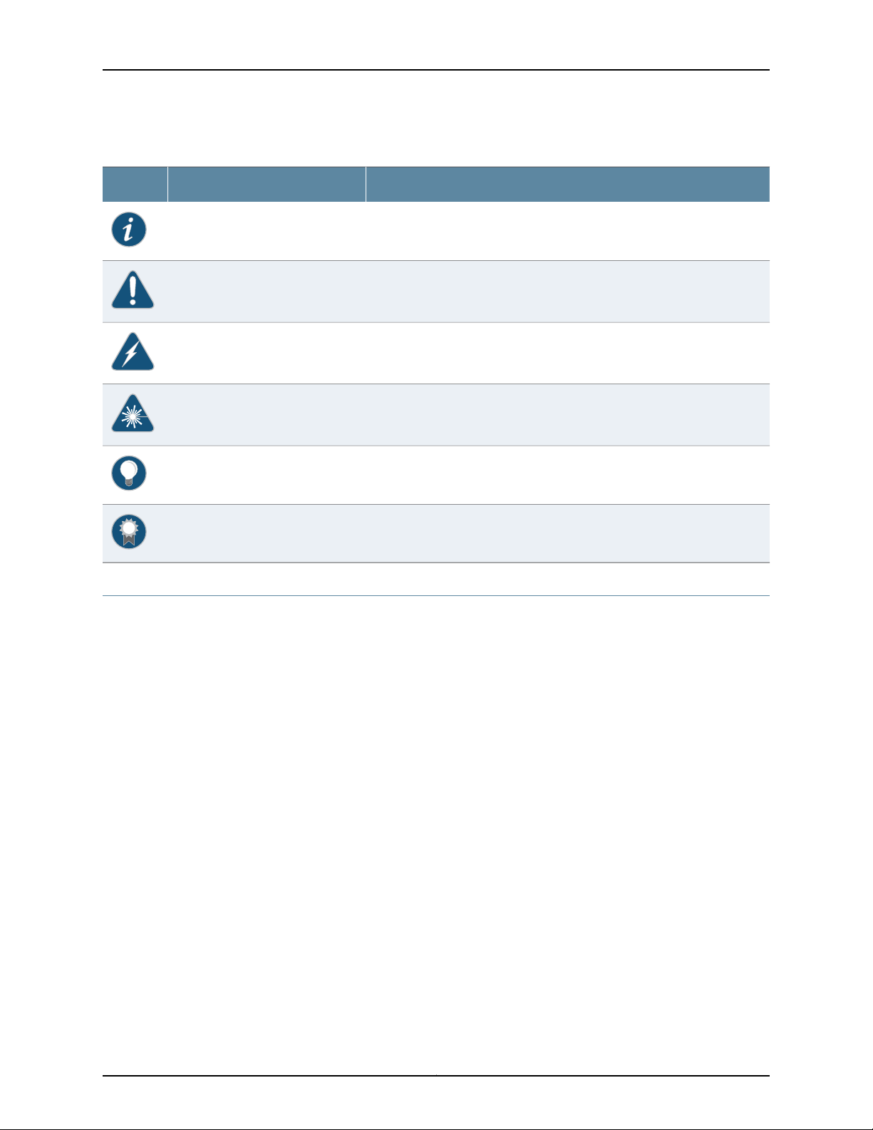
Table 1: Notice Icons
DescriptionMeaningIcon
Indicates important features or instructions.Informational note
Indicates a situation that might result in loss of data or hardware damage.Caution
Alerts you to the risk of personal injury or death.Warning
Alerts you to the risk of personal injury from a laser.Laser warning
Indicates helpful information.Tip
Requesting Technical Support
Technical productsupportisavailable through theJuniper Networks TechnicalAssistance
Center (JTAC). If you are a customer with an active J-Care or Partner Support Service
support contract, or are covered under warranty, and need post-sales technical support,
you can access our tools and resources online or open a case with JTAC.
•
JTAC policies—For a complete understanding of our JTAC procedures and policies,
review the JTAC User Guide located at
http://www.juniper.net/us/en/local/pdf/resource-guides/7100059-en.pdf.
•
Product warranties—For product warranty information, visit
http://www.juniper.net/support/warranty/.
•
JTAC hours of operation—The JTAC centers have resources available 24 hours a day,
7 days a week, 365 days a year.
Self-Help Online Tools and Resources
For quick and easy problem resolution, Juniper Networks has designed an online
self-service portal called the Customer Support Center (CSC) that provides you with the
following features:
Alerts you to a recommended use or implementation.Best practice
•
Find CSC offerings: http://www.juniper.net/customers/support/
•
Search for known bugs: http://www2.juniper.net/kb/
Copyright © 2015, Juniper Networks, Inc.xii
Page 13

•
Find product documentation: http://www.juniper.net/techpubs/
•
Find solutions and answer questions using our Knowledge Base: http://kb.juniper.net/
•
Download the latest versions of software and review release notes:
http://www.juniper.net/customers/csc/software/
•
Search technical bulletins for relevant hardware and software notifications:
http://kb.juniper.net/InfoCenter/
•
Join and participate in the Juniper Networks Community Forum:
http://www.juniper.net/company/communities/
•
Open a case online in the CSC Case Management tool: http://www.juniper.net/cm/
To verifyservice entitlement byproduct serial number, use ourSerial Number Entitlement
(SNE) Tool: https://tools.juniper.net/SerialNumberEntitlementSearch/
Opening a Case with JTAC
You can open a case with JTAC on the Web or by telephone.
About the Documentation
•
Use the Case Management tool in the CSC at http://www.juniper.net/cm/.
•
Call 1-888-314-JTAC (1-888-314-5822 toll-free in the USA, Canada, and Mexico).
For international or direct-dial options in countries without toll-free numbers, see
http://www.juniper.net/support/requesting-support.html.
xiiiCopyright © 2015, Juniper Networks, Inc.
Page 14

Carrier-Grade Service Engine CSE2000 Hardware Installation Guide
Copyright © 2015, Juniper Networks, Inc.xiv
Page 15

PART 1
Carrier-Grade Service Engine CSE2000
Overview
•
CSE2000 Description on page 3
•
Device Features and Specifications on page 5
1Copyright © 2015, Juniper Networks, Inc.
Page 16

Carrier-Grade Service Engine CSE2000 Hardware Installation Guide
Copyright © 2015, Juniper Networks, Inc.2
Page 17

CHAPTER 1
CSE2000 Description
•
Carrier-Grade Service Engine and Active Flow Monitoring Overview on page 3
Carrier-Grade Service Engine and Active Flow Monitoring Overview
Carrier-Grade Service Engine (CSE) is a solution that enables Juniper Networks PTX
Series Packet Transport Routers to improve performance and provide flow monitoring
and accounting services. The CSE2000 device is tethered to a PTX5000 router and
provides support for active flow monitoring version 9. CSE2000 allows scaling of control
plane and service plane, without adding components to the existing PTX routers.
After you connect theCSE2000 to aPTX5000 router, packets matchingthe policy criteria
set for the ingress or egress interfaces on the PTX5000 router are sent to the CSE2000
device for flow monitoring.
Flow monitoring andaccounting services providethe operator information about network
traffic and aid in tasks such as billing, traffic engineering, capacity planning, and traffic
analysis. For more information about active flow monitoring, see the Flow Monitoring
Feature Guide for CSE2000.
CSE2000 Features
CSE2000 is a 2-U device with the following features:
•
Pluggable x86 blades, one or two depending on the configuration, that can be
independently serviced, replaced, and upgraded without affecting the operation of the
other blade.
NOTE: The two x86 blades in the CSE2000 are referredto as service cards
in this documentation.
•
ETSI/NEBS Level 3 compliant
•
Dual CPUs with multicore and multithread computing platform
•
AC and DC power supply support
•
Upgradeable and replaceable hard disks
•
Field-replaceable, hot-swappable, and redundant fans and power supplies
3Copyright © 2015, Juniper Networks, Inc.
Page 18

Carrier-Grade Service Engine CSE2000 Hardware Installation Guide
•
One USB port for each service card
•
Two 10-Gigabit Ethernet with SFP+ ports
Related
Documentation
• CSE2000 Chassis Physical Specifications on page 10
• Environmental Requirements and Specifications for CSE2000 on page 13
Copyright © 2015, Juniper Networks, Inc.4
Page 19

CHAPTER 2
Device Features and Specifications
•
CSE2000 Chassis Overview on page 5
•
CSE2000 Front Panel Features on page 6
•
CSE2000 Rear Panel Features on page 9
•
CSE2000 Chassis Physical Specifications on page 10
CSE2000 Chassis Overview
The Carrier-Grade Service Engine is available in one model: CSE2000. Table 2 on page 5
provides an overview of the chassis features of the CSE2000.
Table 2: CSE2000 Chassis Features
SpecificationCategory
Rack mountable
Traffic interfaces
x86-based service cards
Storage
Fans
There are two mounting mechanisms: four-post rack mount with the sliding rail and
two-post rack mount with four mid-mount brackets.
Four 1-Gigabit Ethernet RJ-45 ports for data traffic and two 10-Gigabit Ethernet ports
for control traffic for each service card.
One RJ-45 serial console port for each service card.Console interface
The CSE2000 can have one or two service cards, depending on requirement and
configuration.
Two USB ports, one for each service card, for software installation or reinstallation.USB interface
Dual-quad core IntelProcessor
32 GB (16 GB per CPU)RAM
Four hard disk drive slots for each service card; eight hard disk drives for the device, if
two service cards are used. Each service card has four 2.5-inch hard disk drives and is
shipped with one SAS 1 TB hard disk.
Twelve 40 mm hot-swappable and redundant fans; six fans at the rear of the chassis
for each service card.
5Copyright © 2015, Juniper Networks, Inc.
Page 20
Carrier-Grade Service Engine CSE2000 Hardware Installation Guide
Table 2: CSE2000 Chassis Features (continued)
SpecificationCategory
When thedevice iscool, thefans spinat a slowerspeed to reduce noise and saveenergy.
As the device heats up, the fans run at a faster speed. In the event of fan failure, the
fault LED blinks and the remaining fan or fans run at full speed.
Power supplies
Removable AC power supply standard: 100 VAC to 240 VAC, 47––63 Hz, 15.0 amperes
(A)maximum. Standard IEC power cord is provided for AC power supply.
Removable DCpowersupply isan availableoption: –45VDC to –60VDC, 35 Amaximum.
NOTE: AC and DC power supplies are not supported simultaneously.
CAUTION: The CSE2000 is NEBS compliant and the fan speed is optimized
for balancing acoustic and cooling conditions based on the system
configurations. Removing any dummy cover or removable component, such
as tray or redundant power supply, changes the system air flow and might
cause overheating of certain components.
Related
Documentation
CSE2000 Front Panel Features on page 6•
• CSE2000 Rear Panel Features on page 9
CSE2000 Front Panel Features
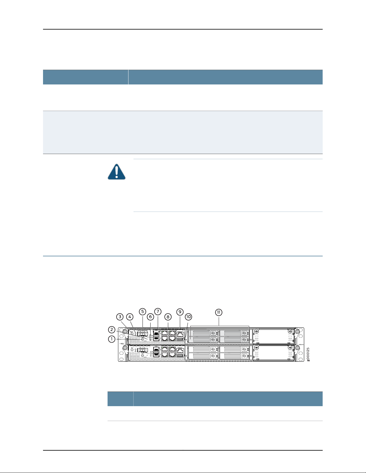
Figure 1 on page 6 shows the CSE2000 front panel features. Table 4 on page 7 describes
the front panel LEDs. Table 4 on page 7 describes the front panel LEDs.
describes the connectivity ports on the CSE2000.
Figure 1: CSE2000 Front Panel Features
Table 3 on page 6 lists the front panel features of CSE2000.
Table 3: CSE2000 Front Panel Features
ComponentNumber
LOCATOR LED and button. The LED can be turned off by pressing the button.1
Copyright © 2015, Juniper Networks, Inc.6
Page 21

Chapter 2: Device Features and Specifications
Table 3: CSE2000 Front Panel Features (continued)
ComponentNumber
2
3
4
5
Power button. This is a recessed button located behind a pinhole to prevent the
CSE2000 from getting powered off accidentally.
Alarm cut off (ACO) button to deactivate alarms from the alarm relay, and this turns
off the Alarm LED.
NOTE: This feature is currently not supported.
Alarm LED, which indicates Telcoalarm trigger. This LED glows whenthe telco function
is enabled and a monitored sensor threshold is reached. Pressing the alarm cut off
button turns off the Telco LED.
NOTE: This feature is currently not supported.
3-pin alarm relay contact to connect to an external alarm bell. Whenever a system
condition triggers either the red or yellow alarm, the alarm relay contacts are also
activated. Use the gauge ofwire appropriatefor theexternaldevice you are connecting.
The alarm relay can beused to monitortemperature, fans, voltage,and power supplies.
NOTE: This feature is currently not supported.
Power LED (green), hard disk access LED (amber), and system warning LED (red)6
10-Gigabit Ethernet ports and LEDs.7
1-Gigabit Ethernet ports and LEDs.8
Serial console port.9
USB port.10
11
Four hard disk drives numbered 0, 1, 2, and 3 on each service card. Shipped with one
SAS 1 TB 2.5-inch hard disk. SAS drives are supported.
Table 4 on page 7 describes the front panel LEDs.
Table 4: CSE2000 Front Panel LEDs
DescriptionLEDs
LOCATOR
Telco
Helps to locate a service card on the rack. The LED is lit blue to identify
the service card. Pressing the button turns off the LED. To active the
Locator LED, see “Activating the LOCATOR LED” on page 58.
Telco LED (red), indicates Telco alarm trigger. This LED glows when the
telco function is enabled and a monitored sensor threshold is reached.
Pressing the alarm cut off button turns off the Telco LED. Telco can
monitor temperature, fans, voltage, and power supplies, and provide
alarms.
7Copyright © 2015, Juniper Networks, Inc.
Page 22

Carrier-Grade Service Engine CSE2000 Hardware Installation Guide
Table 4: CSE2000 Front Panel LEDs (continued)
DescriptionLEDs
Power
Hard disk activityLED
System alarm LED
The power LED (green) glows when the device is powered on and it is off
when the device is powered off.
Hard disk activity LED (amber) glows when the service card is accessing
the hard disk;it blinks momentarily when there is access to the hard disk.
This LED is turned off when there is no access to the hard disk.
The system warning LED (red) blinks slowly to indicate power supply
failure, blinks fast for fan failure, and glows solid when temperature is
above the maximum limit.
Table 5: CSE2000 Connectivity Ports
DescriptionPorts
Console
USB
10-Gigabit Ethernet ports
One RJ-45 serial console port for each service card
to connect to a console server.
One USB port, per service card, for software
installation or reinstallation.
The two 10-Gigabit Ethernet ports are numbered 0
and 1, on each service card. These ports are used to
connect to the10-Gigabit Ethernet PICson PTX5000
routers for data traffic.
NOTE: The 10-GigabitEthernet ports inthe CSE2000
can be connected to 10-Gigabit Ethernet PICs with
10GBASE-SR (model number SFPP-10GE-SR) or
10GBASE-LR (model number SFPP-10GE-LR)
transceivers.
Related
Documentation
1-Gigabit Ethernet ports
The four RJ45 1-Gigabit Ethernet ports for traffic
control are numbered 0, 1, 2, and 3, on each service
card:
•
•
CSE2000 Chassis Overview on page 5•
• CSE2000 Rear Panel Features on page 9
Port 0: For the service card in slot 0, connects to
port X(GE)2 of CB0 (control board) in PTX5000.
For the service card in slot 1, connects to port
X(GE)3 of CB0 in PTX5000.
Port 1: For the service card in slot 0, connects to
port X(GE)2 of CB1 in PTX5000. For the service
card in slot 1, connects to port X(GE)3 of CB1 in
PTX5000. See “Connecting the CSE2000 to a
PTX5000 Router” on page 55.
Copyright © 2015, Juniper Networks, Inc.8
Page 23
CSE2000 Rear Panel Features
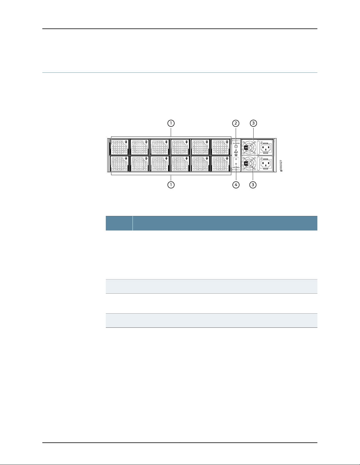
See Figure 2 on page 9 for rear panel features of the CSE2000. This figure shows the
rear panel with AC power supplies.Table 6 on page 9 describes the CSE2000 rear panel
components.
Figure 2: CSE2000 Rear Panel Features
Chapter 2: Device Features and Specifications
Table 6 on page 9 lists rear panel features of the CSE2000.
Table 6: CSE2000 Rear Panel Features
ComponentNumber
1
3
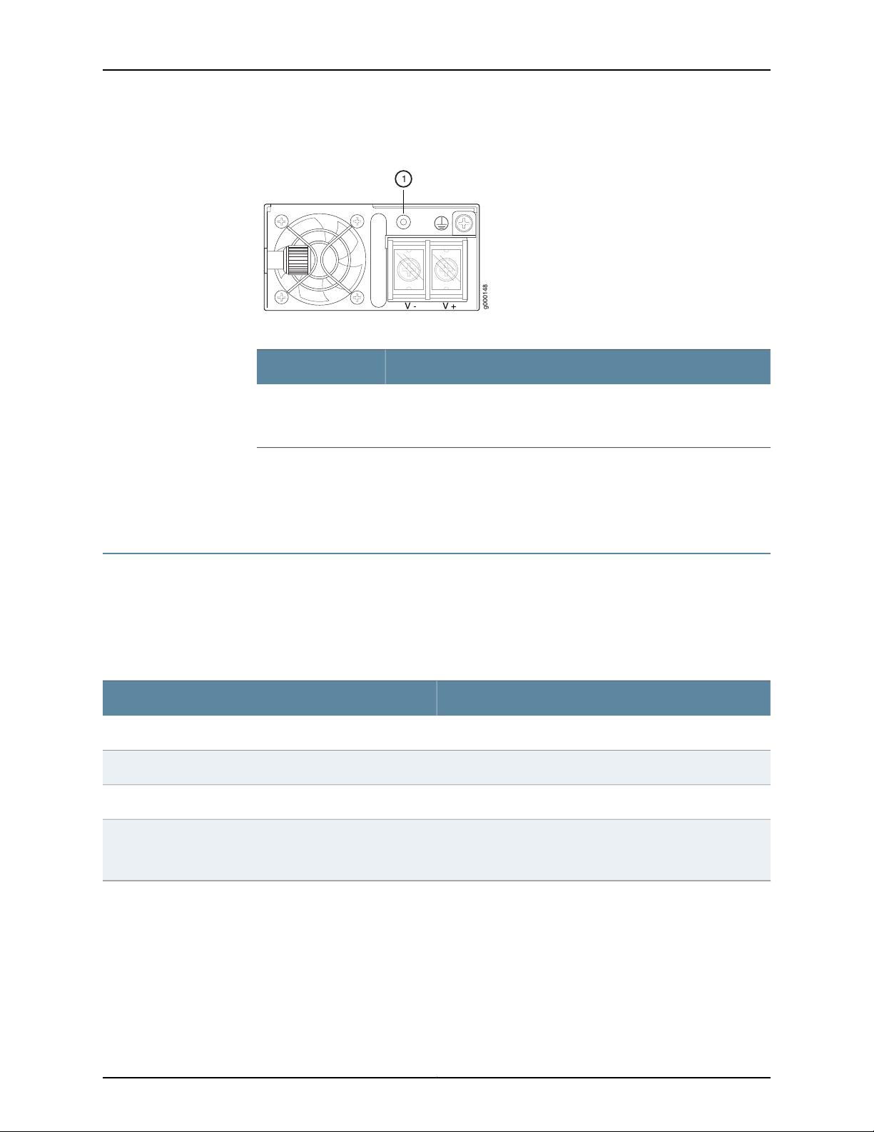
Figure 3 on page 10 shows the DC power supply for the CSE2000 and Table 7 on page 10
describes the LED.
Removable cooling fans. Each service card has six fans numbered 1, 2, 3, 4, 5, and 6
from right to left. The cooling fans draw air through the air inlet on the chassis front
panel and exhaust it through the fan vents on the chassis rear panel. Fans are
redundant and hot-replaceable.
NOTE: When a fan is removed or in case of afan failure, rest of the fans in the service
card operate at full speed.
ESD point to attach the ESD strap.2
Removable AC or DC power supplies with LEDs. Figure 2 on page 9 shows AC power
supplies. There are two AC or DC power supplies for each CSE2000.
Chassis grounding studs to connect the grounding lug and cable.4
9Copyright © 2015, Juniper Networks, Inc.
Page 24
g000148
1
Carrier-Grade Service Engine CSE2000 Hardware Installation Guide
Figure 3: CSE2000 DC Power Supply
Table 7: CSE2000 DC Power Supply LED
DescriptionComponent
The power supply status LED is green when the power supplyis receiving
power and is powering the device. The LED is amber when the power
supply is receiving power but is not powering the device.
Related
Documentation
1
CSE2000 Chassis Overview on page 5•
• CSE2000 Front Panel Features on page 6
CSE2000 Chassis Physical Specifications
The CSE2000 chassis is a rigid sheet-metal structure that houses the hardware
components. Supports mounting in 19 inch rack; the CSE2000 can be mounted on a
four-post rack or a two-post rack. Table 8 on page 10 summarizes the physical
specifications of the CSE2000 chassis.
Table 8: Physical Specifications of the CSE2000 Chassis
ValueDescription
3.46 in. (88 mm)Chassis height
17.27 in. (438.8 mm)Chassis width
20 in. (508 mm)Chassis depth
Weight
Documentation
Related
Fully loaded chassis with two service cards—60 lbs (27.2 kg)
Fully loaded chassis with one service card—44 lbs (20 kg)
• Installing the CSE2000 Chassis in a Rack on page 41
• Rack Requirements for CSE2000 on page 14
Copyright © 2015, Juniper Networks, Inc.10
Page 25

PART 2
Planning
•
Site Preparation on page 13
•
Cable and Pinout Specifications on page 17
•
Planning Power Requirements on page 21
•
Compliance on page 23
11Copyright © 2015, Juniper Networks, Inc.
Page 26

Carrier-Grade Service Engine CSE2000 Hardware Installation Guide
Copyright © 2015, Juniper Networks, Inc.12
Page 27

CHAPTER 3
Site Preparation
•
Environmental Requirements and Specifications for CSE2000 on page 13
•
Rack Requirements for CSE2000 on page 14
•
Clearance Requirements for Airflow and Hardware Maintenance for the
CSE2000 on page 15
•
CSE2000 Chassis Grounding Cable and Lug Specifications on page 15
Environmental Requirements and Specifications for CSE2000
The device must be installed in a rack housed in a dry, clean, well-ventilated, and
temperature-controlled environment.
Ensure that these environmental guidelines are followed:
•
The site must be as dust-free as possible, because dust can clog air intake vents and
filters, reducing the efficiency of the device cooling system.
•
Maintain ambient airflow for normal device operation. If the airflow is blocked or
restricted, or if the intake air is too warm, the device might overheat, causing the device
temperature monitor to power off the device to protect the hardware components.
Table 9 on page14 liststhe required environmental conditions fornormal device operation.
13Copyright © 2015, Juniper Networks, Inc.
Page 28

Carrier-Grade Service Engine CSE2000 Hardware Installation Guide
Table 9: CSE2000 Environmental Tolerances
SpecificationCategory
Ambient temperature
Ambient humidity
Altitude
Related
Documentation
Normal operation: 41°F to 104°F (5°C to 40°C)
Short-term operation: 23°F to 131°F (–5°C to 55°C)
Storage: –40°F to 158°F (–40°C to 70°C)
Relative humidity (operating): Normal—8% to 90% noncondensing; short-term relative
humidity—5% to 90% non-condensing, but not to exceed 0.024 kg water/kg dry air (0.053
lb. water/2.205 lbs. dry air).
Relative humidity (storage): 5% to 95% noncondensing
Operating: 10,000 ft (3048 m) maximum
Storage: 40,000 ft (12,192 m) maximum
Clearance Requirements for Airflow and Hardware Maintenance for the CSE2000 on
•
page 15
Rack Requirements for CSE2000
Before you install a CSE2000 in a rack, you must ensure that the rack complies with a
standard 19-in. (48.26 cm) rack as defined in Cabinets, Racks, Panels, and Associated
Equipment (document number EIA-310-D) published by the Electronics Industry
Association (http://www.eia.org). Refer to this standard for details on rack size and
mounting hole spacing.
When selecting a rack, ensure that the physical characteristics of the rack comply with
the following specifications:
•
You can install the CSE2000 in a four-post rack or a two-post rack.
•
The rack rails must be spaced widely enough to accommodate external dimensions
of the chassis: 3.46 in. (8.8 cm) high, 20 in. (50.8 cm) deep, and 17.27 in. (43.8 cm)
wide. The outer edges of the mounting brackets extend the width to 19.2 in. (48.7 cm).
•
For service personnel to remove and install hardware components, there must be
adequate space at the front and back of the device. Allow at least 30 in. (76.2 cm) in
front of the device and 24 in. (61 cm) behind the device.
•
The rack must be strong enough tosupport the weight ofthe fullyconfigured CSE2000,
up to 60 lb (27.2 kg).
•
The CSE2000 must be installed into a rack that is secured to the building structure.
•
Mount the CSE2000 at the bottom of the rack if it is the only unit in the rack.
•
For the cooling system to function properly, the airflow around the chassis must be
unrestricted. The airflow for the CSE2000 is from front to back.
•
The rack or cabinet must have an adequate supply of cooling air.
Copyright © 2015, Juniper Networks, Inc.14
Page 29

Chapter 3: Site Preparation
•
Ensure that the cabinet allows the hot exhaust air to exit from the cabinet without
recirculating into the device.
•
When mounting the device in a partially filled rack, load the rack from the bottom to
the top with the heaviest component at the bottom of the rack.
•
Use a four-post rack or a two-post rack. The rack must have sufficient vertical usable
space to accommodate the height of the device: 3.46 in (88 mm), or 2 U.
NOTE: A U is the standard rack unit defined in Cabinets, Racks, Panels, and
Associated Equipment (document number EIA-310-D) published by the
Electronics Industry Association.
•
You must use only copper grounding conductors.
Related
Documentation
General Safety Guidelines and Warnings for CSE2000 on page 29•
• CSE2000 Chassis Physical Specifications on page 10
• Clearance Requirements for Airflow and Hardware Maintenance for the CSE2000 on
page 15
Clearance Requirements for Airflow and Hardware Maintenance for the CSE2000
When planning the installation site, allow sufficient clearance around the rack.
•
For the cooling system to function properly, the airflow around the chassis must be
unrestricted:
•
Allow at least 6 in. (15.2 cm) of clearance on the side between devices that have
fans or blowers installed.
•
Allow 2.8 in. (7 cm) between the side of the chassis and any non-heat-producing
surface such as a wall.
•
Ensure that the airflow vents remain open and uncovered for proper cooling.
•
For service personnel to remove and install hardware components, there must be
adequate space at the front and back of the device. At least 24 in. (61.0 cm) is required
both in front of and behind the chassis. The front ofthe chassis extends approximately
0.5 in. (1.27 cm) beyond the mounting ears.
Related
Rack Requirements for CSE2000 on page 14•
Documentation
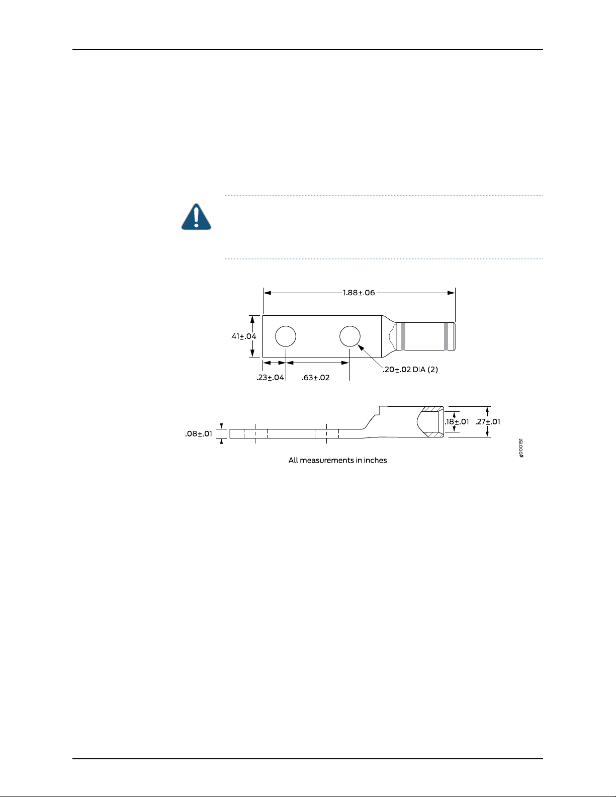
CSE2000 Chassis Grounding Cable and Lug Specifications
NOTE: The grounding lug, cable, screws, and nuts are provided by Juniper
Networks.
15Copyright © 2015, Juniper Networks, Inc.
Page 30
Carrier-Grade Service Engine CSE2000 Hardware Installation Guide
To meet safety and electromagnetic interference (EMI) requirements and to ensure
proper operation, theCSE2000 mustbe adequately groundedbefore power isconnected.
Two bolts areprovided at therear ofthe chassis for connecting the routerto earth ground.
Four 8-32 nuts are provided to secure the grounding lug to the bolts.
The grounding cable must be 6-AWG (13.3 mm2) or higher. Figure 4 on page 16 shows
the grounding lug that attaches to the grounding cable.
CAUTION: Before you begin installation of the CSE2000, a licensed electrician
must attach a cable lug to the grounding cable. A cable with an incorrectly
attached lug can damage the device.
Figure 4: Grounding Cable Lug
Related
Documentation
• Tools and Parts Required to Ground the CSE2000 on page 45
• Connecting the CSE2000 Grounding Cable on page 45
Copyright © 2015, Juniper Networks, Inc.16
Page 31

CHAPTER 4
Cable and Pinout Specifications
•
RJ-45 Console Connector Pinout for the CSE2000 on page 17
•
AC Power Cord Specifications for the CSE2000 on page 17
RJ-45 Console Connector Pinout for the CSE2000
Table 10 on page 17 describes the pinout for the RJ-45 console port connector.
Table 10: RJ-45 Console Connector Pinout
DescriptionSignalPin
Request to SendRTS Output1
Data Terminal ReadyDTR Output2
Transmit DataTxD Output3
Related
Documentation
Connecting a Console Server to the CSE2000 on page 49•
AC Power Cord Specifications for the CSE2000
Detachable AC power cords are supplied with the AC-powered CSE2000. The coupler
is type C13 as described by International Electrotechnical Commission (IEC) standard
60320. The plug at the male end of the power cord fits into the power source outlet that
is standard for your geographical location.
Chassis GroundGND4
Chassis GroundGND5
Receive DataRxD Input6
Data Set ReadyDSR Input7
Clear to SendCTS Input8
17Copyright © 2015, Juniper Networks, Inc.
Page 32

Carrier-Grade Service Engine CSE2000 Hardware Installation Guide
CAUTION: The AC power cord supplied with the device is intended for use
with that device only and not for any other use.
Power Cable Warning (Japanese)
WARNING: The attached power cable is only for this product. Do not use the cable for another
product.
NOTE: In North America, AC power cords must not exceed 4.5 meters
(approximately 14.75feet) in length, to comply with National ElectricalCode
(NEC) Sections 400-8 (NFPA 75, 5-2.2) and 210-52 and Canadian Electrical
Code (CEC) Section 4-010(3). The cords supplied with the device are in
compliance.
Table 11 on page 18 lists AC power cord specifications provided foreach country or region.
Table 11: AC Power Cord Specifications for the CSE2000
United Kingdom)
Plug StandardsElectrical SpecificationsCountry/Region
AS/NZ 3112250 VAC, 10 A, 50 HzAustralia
GB2099 and GB1002250 VAC, 10 A, 50 HzChina
CEE (7) VII250 VAC, 10 A, 50 HzEurope (except Italy, Switzerland, and
CEI 23-16250 VAC, 10 A, 50 HzItaly
JIS C8303125 VAC, 12 A, 50 or 60 HzJapan
NEMA 5-15125 VAC, 13 A, 60 HzNorth America
Related
Documentation
SEV 1011 SEV 6534/2250 VAC, 10 A, 50 HzSwitzerland
BS 1363/A250 VAC, 10 A, 50 HzUnited Kingdom
• Connecting Power to AC-Powered CSE2000 on page 47
• General Safety Guidelines and Warnings for CSE2000 on page 29
Copyright © 2015, Juniper Networks, Inc.18
Page 33

Chapter 4: Cable and Pinout Specifications
• General Electrical Safety Guidelines and Warnings for CSE2000 on page 31
• AC Power Electrical Safety Guidelines for CSE2000 on page 32
• Prevention of Electrostatic Discharge Damage on CSE2000 on page 34
19Copyright © 2015, Juniper Networks, Inc.
Page 34

Carrier-Grade Service Engine CSE2000 Hardware Installation Guide
Copyright © 2015, Juniper Networks, Inc.20
Page 35

CHAPTER 5
Planning Power Requirements
•
Power Specifications for the CSE2000 on page 21
Power Specifications for the CSE2000
This topic describes the power supply electrical specifications for the CSE2000. An AC
power supply is standard, while a DC power supply is an available option.
Table 12 on page 21 lists the AC power supply and Table 13 on page 21 lists the DC power
supply electrical specifications for the CSE2000.
Table 12: AC Power Supply Electrical Specifications for CSE2000
SpecificationItem
100 VAC through 240 VACAC input voltage
50 or 60 HzAC input line frequency
8 A through 4 A (nominal) per power supplyAC system current rating
80+%AC minimum efficiency
Table 13: DC Power Supply Electrical Specifications for CSE2000
SpecificationItem
–48 VDC through –60 VDCDC input voltage
16 A (maximum) per power supplyDC system current rating
80+%DC minimum efficiency
Related
Documentation
• General Electrical Safety Guidelines and Warnings for CSE2000 on page 31
• AC Power Cord Specifications for the CSE2000 on page 17
• Connecting Power to AC-Powered CSE2000 on page 47
• Connecting Power to a DC-Powered CSE2000 Device on page 48
21Copyright © 2015, Juniper Networks, Inc.
Page 36

Carrier-Grade Service Engine CSE2000 Hardware Installation Guide
Copyright © 2015, Juniper Networks, Inc.22
Page 37

CHAPTER 6
Compliance
•
Agency Approvals for CSE2000 on page 23
•
CSE2000 Compliance Statements for NEBS on page 23
Agency Approvals for CSE2000
The CSE2000 device complies with the following standards:
•
Safety
•
CAN/CSA-C22.2 No. 60950-1
•
EN 60950
•
IEC 60950-1
•
UL 60950-1
•
EMC
•
FCC Class A
•
EN 55022 Class A
•
EN 55024 Immunity
•
EN 61000-3-2
•
VCCI Class A
Related
Documentation
CSE2000 Compliance Statements for NEBS
•
The equipment is suitable for installation as part of the Common Bonding Network
(CBN).
•
The equipment is suitable for installation in locations where the National Electrical
Code (NEC) applies.
•
The battery return connection is to be treated as an isolated DC return (i.e. DC-I), as
defined in GR-1089-CORE.
23Copyright © 2015, Juniper Networks, Inc.
Page 38

Carrier-Grade Service Engine CSE2000 Hardware Installation Guide
Related
Documentation
• Agency Approvals for CSE2000 on page 23
Copyright © 2015, Juniper Networks, Inc.24
Page 39

PART 3
Safety
•
General Safety Guidelines and Warnings on page 27
•
Electrical Safety Guidelines and Warnings on page 31
25Copyright © 2015, Juniper Networks, Inc.
Page 40

Carrier-Grade Service Engine CSE2000 Hardware Installation Guide
Copyright © 2015, Juniper Networks, Inc.26
Page 41

CHAPTER 7
General Safety Guidelines and Warnings
•
Definition of Safety Warning Levels for CSE2000 on page 27
•
General Safety Guidelines and Warnings for CSE2000 on page 29
Definition of Safety Warning Levels for CSE2000
The CSE2000 documentation uses the following levels of safety warnings:
NOTE: You might find this information helpful in a particular situation or
might otherwise overlook it.
CAUTION: You must observe the specified guidelines to avoid minor injury
or discomfort to you or severe damage to the equipment.
WARNING: This symbol means danger.You are in a situation that couldcause
bodily injury. Before you work on any equipment, be aware of the hazards
involved with electrical circuitry and be familiar with standard practices for
preventing accidents.
Waarschuwing Dit waarschuwingssymbool betekent gevaar. U verkeert in
een situatie die lichamelijk letsel kan veroorzaken. Voordat u aan enige
apparatuur gaat werken, dient u zich bewust te zijn van de bij elektrische
schakelingen betrokken risico's en dient u op de hoogte te zijn van standaard
maatregelen om ongelukken te voorkomen.
Varoitus Tämä varoitusmerkki merkitsee vaaraa. Olet tilanteessa, joka voi
johtaa ruumiinvammaan. Ennen kuin työskenteletminkään laitteistonparissa,
ota selvää sähkökytkentöihin liittyvistä vaaroista ja tavanomaisista
onnettomuuksien ehkäisykeinoista.
Attention Ce symbole d'avertissement indique un danger. Vous vous trouvez
dans une situation pouvant causer des blessures ou des dommages corporels.
Avant de travailler sur un équipement, soyez conscient des dangers posés
27Copyright © 2015, Juniper Networks, Inc.
Page 42

Carrier-Grade Service Engine CSE2000 Hardware Installation Guide
par les circuits électriques et familiarisez-vous avec les procédures
couramment utilisées pour éviter les accidents.
Warnung Dieses Warnsymbol bedeutet Gefahr. Sie befinden sich in einer
Situation, die zu einer Körperverletzung führen könnte. Bevor Sie mit der
Arbeit an irgendeinem Gerät beginnen, seien Sie sich der mit elektrischen
Stromkreisen verbundenen Gefahren und der Standardpraktiken zur
Vermeidung von Unfällen bewußt.
Avvertenza Questo simbolo di avvertenza indica un pericolo. La situazione
potrebbe causare infortuni alle persone. Prima di lavorare su qualsiasi
apparecchiatura, occorre conoscere i pericoli relativi ai circuiti elettrici ed
essere al corrente delle pratiche standard per la prevenzione di incidenti.
Advarsel Dette varselsymbolet betyr fare. Du befinner deg i en situasjon som
kan føre til personskade. Før du utfører arbeid på utstyr, må du vare
oppmerksom på de faremomentene som elektriske kretser innebærer, samt
gjøre deg kjent med vanlig praksis når det gjelder å unngå ulykker.
Related
Documentation
Aviso Este símbolo de aviso indica perigo. Encontra-se numa situação que
lhe poderá causar danos físicos. Antes de começar a trabalhar com qualquer
equipamento, familiarize-se com os perigos relacionados com circuitos
eléctricos, e com quaisquer práticas comuns que possam prevenir possíveis
acidentes.
¡Atención! Este símbolo de aviso significa peligro. Existe riesgo para su
integridad física. Antes de manipular cualquier equipo, considerar los riesgos
que entraña la corriente eléctrica y familiarizarse con los procedimientos
estándar de prevención de accidentes.
Varning!Denna varningssymbol signalerar fara. Du befinner dig i en situation
som kan leda till personskada. Innan du utför arbete på någon utrustning
måste du vara medveten om farorna med elkretsar och känna till vanligt
förfarande för att förebygga skador.
General Safety Guidelines and Warnings for CSE2000 on page 29•
• General Electrical Safety Guidelines and Warnings for CSE2000 on page 31
• AC Power Electrical Safety Guidelines for CSE2000 on page 32
• DC Power Electrical Safety Guidelines for CSE2000 on page 33
Copyright © 2015, Juniper Networks, Inc.28
Page 43

General Safety Guidelines and Warnings for CSE2000
The following guidelines help ensure your safety and protect the CSE2000 device from
damage. The list of guidelines might not address all potentially hazardous situations in
your working environment, so be alert and exercise good judgment at all times.
WARNING: WARNING: Certain ports on the device are designed for use as
intrabuilding (within-the-building) interfaces only (Type 2 or Type 4 ports as
described in GR-1089-CORE) and require isolation from the exposed outside
plant (OSP) cabling. To comply with NEBS requirements and protect against
lightning surges and commercial power disturbances, the intrabuilding ports
must not be metallically connected to interfaces that connect to the OSP or
its wiring. The intrabuilding ports on the device are suitable for connection
to intrabuilding or unexposed wiring or cabling only. The addition of primary
protectors is not sufficient protection for connecting these interfaces
metallically to OSP wiring.
Chapter 7: General Safety Guidelines and Warnings
WARNING: The intra-building port(s) (including the following ports, when
present: DAC, External Clock, Internal Clock, T1/E1, POE Ethernet) of the
equipment or subassembly must use shielded intra-building cabling/wiring
that is grounded at both ends.
•
Perform only the procedures explicitly described in the hardware documentation for
this product. Make sure that only authorized service personnel perform other system
services.
•
Keep the area around the chassis clear and free from dust before, during, and after
installation.
•
Keep tools away from areas where people could trip over them while walking.
•
Do not wear loose clothing or jewelry, such as rings, bracelets, or chains, which could
become caught in the chassis.
•
Wear safety glasses if you are working under any conditions that could be hazardous
to your eyes.
•
Do not perform any actions that create a potential hazard to people or make the
equipment unsafe.
•
Never attempt to lift an object that is too heavy for one person to handle.
•
Never install or manipulate wiring during electrical storms.
•
Never install electrical jacks in wet locations unless the jacks are specifically designed
for wet environments.
•
Operate the device only when it is properly grounded.
29Copyright © 2015, Juniper Networks, Inc.
Page 44

Carrier-Grade Service Engine CSE2000 Hardware Installation Guide
•
Ensure that a reliable, low-resistance ground bond exists between the chassis and the
rack, and that the rack is permanently connected to earth.
•
Use only copper grounding conductors.
•
Ensure that the separate protective earthing terminal on this product, if provided, is
permanently connected to earth.
•
Do not open or remove chassis covers or sheet-metal parts unless instructions are
provided in the hardware documentation for this product. Such an action could cause
severe electrical shock.
•
Do not push or force any objects through any opening in the chassis frame. Such an
action could result in electrical shock or fire.
•
Avoid spilling liquid onto the chassis or onto any component. Such an action could
cause electrical shock or damage the device.
•
Avoid touching uninsulated electrical wires or terminals that have not been
disconnected from their power source. Such an action could cause electrical shock.
•
Always ensure that all modules, power supplies, and cover panels are fully inserted
and that the installation screws are fully tightened.
Related
Documentation
• Definition of Safety Warning Levels for CSE2000 on page 27
• General Electrical Safety Guidelines and Warnings for CSE2000 on page 31
• AC Power Electrical Safety Guidelines for CSE2000 on page 32
• DC Power Electrical Safety Guidelines for CSE2000 on page 33
Copyright © 2015, Juniper Networks, Inc.30
Page 45

CHAPTER 8
Electrical Safety Guidelines and Warnings
•
General Electrical Safety Guidelines and Warnings for CSE2000 on page 31
•
AC Power Electrical Safety Guidelines for CSE2000 on page 32
•
DC Power Electrical Safety Guidelines for CSE2000 on page 33
•
Prevention of Electrostatic Discharge Damage on CSE2000 on page 34
General Electrical Safety Guidelines and Warnings for CSE2000
CAUTION: Certain ports on the device are designed for use as intrabuilding
(within-the-building) interfaces only (Type 2 or Type 4 ports as described in
GR-1089-CORE,Issue 4) and requireisolation from the exposed outside plant
(OSP) cabling. To comply with NEBS requirements and protect against
lightning surges and commercial power disturbances, the intrabuilding ports
must not be metallically connected to interfaces that connect to the OSP or
its wiring. The intrabuilding ports on the device are suitable for connection
to intrabuilding or unexposed wiring or cabling only. The addition of primary
protectors is not sufficient protection for connecting these interfaces
metallically to OSP wiring.
CAUTION: Before removing or installing device components, attach an ESD
strap to an ESD point, and place the other end of the strap around your bare
wrist. Failure to use an ESD strap could result in damage to the device.
•
Install the CSE2000 in compliance with thefollowing local, national,and international
electrical codes:
•
United States—National Fire Protection Association (NFPA 70), United States
National Electrical Code.
•
Other countries—International Electromechanical Commission (IEC) 60364, Part 1
through Part 7.
31Copyright © 2015, Juniper Networks, Inc.
Page 46

Carrier-Grade Service Engine CSE2000 Hardware Installation Guide
•
Evaluated to the TN power system.
•
Canada—Canadian Electrical Code, Part 1, CSA C22.1.
•
Note the following warning printed on the chassis:
The equipment must be connected to an earthed mains socket-outlet.
•
Locate the emergency power-off switch for the room in which you are working so that
if an electrical accident occurs, you can quickly turn off the power.
•
Make sure thatgrounding surfaces are cleaned before you make groundingconnections.
•
Do notwork alone ifpotentially hazardous conditionsexist anywhere in your workspace.
•
Never assume thatpower is disconnectedfrom acircuit. Always check the circuit before
starting to work.
•
Carefully look for possible hazards in your work area, such as moist floors, ungrounded
power extension cords, and missing safety grounds.
•
Operatethe CSE2000within markedelectrical ratings andproduct usage instructions.
•
To ensure that the CSE2000 and peripheral equipment function safely and correctly,
use the cables and connectors specified for the attached peripheral equipment, and
make certain they are in good condition.
You can remove and replace some components without powering off or disconnecting
power to the device, as detailed elsewhere in the hardware documentation for this
product. Never install equipment if it appears damaged.
Related
Documentation
Definition of Safety Warning Levels for CSE2000 on page 27•
• General Safety Guidelines and Warnings for CSE2000 on page 29
• AC Power Electrical Safety Guidelines for CSE2000 on page 32
• DC Power Electrical Safety Guidelines for CSE2000 on page 33
AC Power Electrical Safety Guidelines for CSE2000
The following electrical safety guidelines apply to AC-powered devices:
•
AC-powered devices are shipped with a three-wire electrical cord with agrounding-type
plug that fits only agrounding-type power outlet. Do not circumventthis safety feature.
Equipment grounding must comply with local and national electrical codes.
•
The power cord serves as the main disconnecting device for the device. The socket
outlet must be near the device and be easily accessible.
•
For CSE2000 devices that have more than one power supply connection, you must
ensure that all power connections are fully disconnected so that power to the device
is completely removed to avoid electric shock. To disconnect power, unplug all power
cords (one for each power supply).
Copyright © 2015, Juniper Networks, Inc.32
Page 47

Chapter 8: Electrical Safety Guidelines and Warnings
CAUTION: The AC power cord for the devices is intended for use with that
device only and not for any other use.
Power Cable Warning (Japanese)
WARNING: The attached power cable is only for this product. Do not use the cable for another
product.
Related
Documentation
Definition of Safety Warning Levels for CSE2000 on page 27•
• General Safety Guidelines and Warnings for CSE2000 on page 29
• General Electrical Safety Guidelines and Warnings for CSE2000 on page 31
• Connecting Power to AC-Powered CSE2000 on page 47
DC Power Electrical Safety Guidelines for CSE2000
The following electrical safety guidelines apply to a DC-powered device:
•
A DC-powered device is equipped with a DC terminal block that is rated for the power
requirements of a maximally configured device.
NOTE: To supply sufficient power, terminate the DC input wiring on a facility
DC source capable of supplying at least 25 A at –48 VDC (minimum
–45VDC and maximum –60VDC).
Incorporate an easily accessible disconnect device into the facility wiring. Be sure to
connect the ground wire or conduit to a solid office earth ground. We recommend a
closed loop ring for terminating the ground conductor at the ground stud.
•
You must use only copper grounding conductors.
•
Run two wires from the circuit breaker box to a source of 48 VDC.
•
You must provide anexternal certified circuitbreaker rated minimum 25 A in thebuilding
installation.
•
A DC-powered device that is equipped with a DC terminal block is intended only for
installation in a restricted access location. In the United States, a restricted access
area is one inaccordancewith Articles 110-16,110-17, and 110-18 of the National Electrical
Code ANSI/NFPA 70.
33Copyright © 2015, Juniper Networks, Inc.
Page 48

Carrier-Grade Service Engine CSE2000 Hardware Installation Guide
CAUTION: Primary overcurrentprotectionis providedby the building circuit
breaker. This breaker must protect against excess currents, short circuits,
and earth-grounding faults in accordance with NEC ANSI/NFPA 70.
•
Ensure that the polarity of the DC input wiring is correct. Under certain conditions,
connections with reversed polarity might trip the primary circuit breaker or damage
the equipment.
•
For personal safety, connect a wire for earth ground at both the device and the supply
side of the DC wiring.
•
The marked input voltage of –48 VDC for a DC-powered device is the nominal voltage
associated with the battery circuit, and any higher voltages are to be associated only
with float voltages for the charging function.
•
Because the device is a positive ground system, you must connect the positive lead to
the terminal labeled RTN, the negative lead to the terminal labeled –48 VDC, and the
earth ground to the chassis grounding points.
Related
Documentation
Definition of Safety Warning Levels for CSE2000 on page 27•
• General Safety Guidelines and Warnings for CSE2000 on page 29
• Connecting Power to a DC-Powered CSE2000 Device on page 48
Prevention of Electrostatic Discharge Damage on CSE2000
The CSE2000 components that are shipped in antistatic bags are sensitive to damage
from static electricity. Some components can be impaired by voltages as low as 30 V.
You can easilygeneratepotentially damaging staticvoltages whenever you handle plastic
or foam packing material or if you move components across plastic or carpets. Observe
the following guidelines to minimize the potential for electrostatic discharge (ESD)
damage, which can cause intermittent or complete component failures:
•
Always usean ESDgrounding strap when you are handling components thatare subject
to ESD damage, and make sure that it is in direct contact with your skin.
If a grounding strap is not available, hold the component in its antistatic bag in one
hand, and touch the exposed,bare metal ofthe device withthe other hand immediately
before inserting the component into the device.
CAUTION: For safety, periodically check the resistance value of the ESD
strap. The measurement must be in the range of 1 through 10 Mohms.
•
Avoidcontact between thecomponent that is subjectto ESD damage andyour clothing.
ESD voltages emitted from clothing can damage components.
•
When removing orinstalling a component that is subject to ESD damage, always place
it component-side up on an antistatic surface, in an antistatic card rack, or in an
Copyright © 2015, Juniper Networks, Inc.34
Page 49

Chapter 8: Electrical Safety Guidelines and Warnings
antistatic bag. If you are returning a component, place it in an antistatic bag before
packing it.
CAUTION: ANSI/TIA/EIA-568 cables such as category 5e and category 6
can get electrostatically charged. To dissipate this charge, always ground
the cables to a suitable and safe earth ground before connecting them to the
system.
Related
Documentation
• Definition of Safety Warning Levels for CSE2000 on page 27
• General Safety Guidelines and Warnings for CSE2000 on page 29
• Connecting the CSE2000 Grounding Cable on page 45
35Copyright © 2015, Juniper Networks, Inc.
Page 50

Carrier-Grade Service Engine CSE2000 Hardware Installation Guide
Copyright © 2015, Juniper Networks, Inc.36
Page 51

PART 4
Installation
•
Preparing the Installation on page 39
•
Installing the CS2000 Device on page 41
•
Grounding the CSE2000 on page 45
•
Cabling on page 47
•
Powering On on page 51
37Copyright © 2015, Juniper Networks, Inc.
Page 52

Carrier-Grade Service Engine CSE2000 Hardware Installation Guide
Copyright © 2015, Juniper Networks, Inc.38
Page 53

CHAPTER 9
Preparing the Installation
•
Unpacking and Inspecting the CSE2000 on page 39
•
Before You Install the CSE2000 on page 40
Unpacking and Inspecting the CSE2000
The CSE2000 is shipped in a box. Quick Start installation instructions and a cardboard
accessory box are also included in the shipping box.
NOTE: The device is maximally protected inside the shipping box. Do not
unpack it until you are ready to begin installation.
Before you begin unpacking the device, be sure you have the following tools and parts:
•
Phillips (+) screwdriver, number 2 (not provided)
•
Electrostatic discharge (ESD) grounding wrist strap (not provided)
•
Mid-mount brackets for two-post mount
•
Sliding rails and rail assembly for four-post mount
To unpack the device:
1. Move the shipping box to a staging area as close to the installation site as possible,
where you have enough room to maneuver.
2. Position the shipping box with the arrows pointing up.
3. Open the shipping box.
4. Remove the accessory box and the Quick Start installation instructions.
5. Verify the parts received.
6. Save the shipping box and packing materials in case you need to move or ship the
device at a later time.
39Copyright © 2015, Juniper Networks, Inc.
Page 54

Carrier-Grade Service Engine CSE2000 Hardware Installation Guide
After you remove the equipment from the shipping boxes:
•
Confirm the contents of each box.
•
Inspect all external surfaces and external connectors for visible signs of damage.
•
Inspect all accessories in the accessory box.
•
Document any damage noted during your inspection.
•
Confirm that theplatformhas the correctnumber andtype ofmodules for your ordered
configuration.
If you detect or suspect damage to any equipment:
•
Contact the shipper responsible for delivery, and formally report the damage.
•
Contact Juniper Networks at 1-888-314-JTAC (from the United States, Canada, or
Mexico) or 1-408-745-9500 (from elsewhere), or contact your sales representative
or reseller if you have any questions or concerns.
Related
Returning CSE2000 Hardware for Repair or Replacement on page 73•
Documentation
Before You Install the CSE2000
Before installing the CSE2000:
•
Verify that the site meets all environment specifications. See “Environmental
Requirements and Specifications for CSE2000” on page 13.
•
Read and understand the clearance requirements for the device to ensure adequate
ventilation and enable access to the device for maintenance. See “Clearance
Requirements for Airflow and Hardware Maintenance for the CSE2000” on page 15.
•
Have the tools and accessories needed to complete the installation. See “Unpacking
and Inspecting the CSE2000” on page 39.
•
Verify that the cables you plan to use meet the specifications, and review the cabling
recommendations. See “AC Power Cord Specifications for the CSE2000” on page 17.
Have plastic cable ties or other means to secure traffic and power cables safely out
of the way.
•
Verify that the electrical supply meets all AC or DC power requirements. See “Power
Specifications for the CSE2000” on page 21.
Related
Documentation
• Installing the CSE2000 Chassis in a Rack on page 41
Copyright © 2015, Juniper Networks, Inc.40
Page 55

CHAPTER 10
Installing the CS2000 Device
•
Installing the CSE2000 Chassis in a Rack on page 41
•
Installing the CSE2000 in a Two-Post Rack on page 42
•
Installing the CSE2000 in a Four-Post Rack on page 42
Installing the CSE2000 Chassis in a Rack
To install the CSE2000:
1. Place the shipping container on a flat surface, and remove the hardware components
with care.
CAUTION: Place the shipping container on a flat surface, and remove the
hardware components with care.
2. The CSE2000 can be installed in a two-post rack or a four-post rack. For two-post
rack installations, see “Installing the CSE2000 in a Two-Post Rack” on page 42. For
four-post rack installation, see “Installing the CSE2000 in a Four-Post Rack” on
page 42.
3. Secure the device to the rack with thread-forming screws, and place external-tooth,
paint-piercing lock washers between the screw head and the mounting bracket to
create a reliable low-resistance ground bond between the chassis and the rack.
4. Connect power to the device.
For a standard, AC-power-equipped CSE2000, plug the supplied AC power cord into
the receptacle on the rear panel. See
If you have a DC-power-equipped CSE2000, see
5. To connect to a console terminal, plug the supplied Ethernet cable into the console
port on the front panel.
6. Power on the device. See
When you turn on the power, the power LED (green) glows. See LED details.
7. To connect to your management network, plug an RJ-45 cable to 1-Gigabit Ethernet
port 2 on the front panel.
41Copyright © 2015, Juniper Networks, Inc.
Page 56

Carrier-Grade Service Engine CSE2000 Hardware Installation Guide
Related
Before You Install the CSE2000 on page 40•
Documentation
Installing the CSE2000 in a Two-Post Rack
CAUTION: Due to the size and weight of CSE2000—up to 60 lb (27.2 kg)
with two service cards and 44 lb (20 kg) with one service card—we
recommend that you install the device with two people (one to lift and one
to secure the device to the rack).
To install the CSE2000 in a two-post rack:
1. Attach the ESD grounding strap to your bare wrist and to a site ESD point.
2. Fix one mid-mount bracket with screws on either side of the chassis.
3. Fix the chassis to the equipment rack with mounting screws in the two slots. Fix the
other two mid-mountbracketson eitherside of the systemand thensecure the chassis
to the backs of the posts (see Figure 5 on page 42).
Figure 5: Install CSE2000 in a Two-Post Rack
Related
Documentation
Before You Install the CSE2000 on page 40•
• Rack Requirements for CSE2000 on page 14
• Clearance Requirements for Airflow and Hardware Maintenance for the CSE2000 on
page 15
Installing the CSE2000 in a Four-Post Rack
CAUTION: Due to the size and weight of CSE2000—up to 60 lb (27.2 kg)
with two service cards and 44 lb (20 kg) with one service card—we
recommend that you install the device with two people (one to lift and one
to secure the device to the rack).
Copyright © 2015, Juniper Networks, Inc.42
Page 57

g000145
Chapter 10: Installing the CS2000 Device
To install the CSE2000 in a four-post rack:
1. Attach the ESD grounding strap to your bare wrist and to a site ESD point.
2. Remove theslide railsfrom theslide railassembly. You have to push the stopper down
to remove the rails.
3. Insert four screws and fix the slide rails on each side of the device. See
Figure 6 on page 43
4. Adjust the length of the two rack assemblies and fix them to your equipment rack.
Ensure that you identify the left and right rack assemblies, as marked on the
assemblies, and install accordingly.
5. Align the slide rails on either side of the chassis with the rack assemblies, push the
stopper down and slide the chassis fully into the rack enclosure. See
Figure 7 on page 43.
6. Insert two rack mount screws eachin tothe twomount brackets infront of the chassis
to secure the chassis to the equipment rack. See Figure 7 on page 43.
7. Verify that the mounting screws on one side of the rack are aligned with the mounting
screws on the opposite side and that the appliance is level.
Related
Documentation
Figure 6: Fixing Chassis Rack Rail
Figure 7: Installing the Chassis in a Four-Post Rack
• Before You Install the CSE2000 on page 40
• Rack Requirements for CSE2000 on page 14
• Clearance Requirements for Airflow and Hardware Maintenance for the CSE2000 on
page 15
43Copyright © 2015, Juniper Networks, Inc.
Page 58

Carrier-Grade Service Engine CSE2000 Hardware Installation Guide
Copyright © 2015, Juniper Networks, Inc.44
Page 59

CHAPTER 11
Grounding the CSE2000
•
Tools and Parts Required to Ground the CSE2000 on page 45
•
Connecting the CSE2000 Grounding Cable on page 45
Tools and Parts Required to Ground the CSE2000
To ground the CSE2000, you need the following tools and parts:
•
ESD grounding wrist strap (not provided)
•
Four 8-32 nuts—two nuts each are fastened to the two earthing bolts on the rear panel
of the chassis when shipped
•
Grounding lug
•
Grounding cable
Related
Documentation
CSE2000 Rear Panel Features on page 9•
• CSE2000 Chassis Grounding Cable and Lug Specifications on page 15
• Prevention of Electrostatic Discharge Damage on CSE2000 on page 34
Connecting the CSE2000 Grounding Cable
BEST PRACTICE: The grounding points for the CSE2000 are at the rear of
the chassis. See “CSE2000 Rear Panel Features” on page 9.
To connect the grounding cable:
1. Make sure that grounding surfaces are clean before grounding connections are made.
2. Connect the grounding cable to a proper earth ground.
3. Verify that a licensed electrician has attached the cablelug provided with the CSE2000
device to the grounding cable.
4. Attach an electrostaticdischarge (ESD) groundingstrap to yourbare wrist,and connect
the strap to an approved ESD grounding point.
45Copyright © 2015, Juniper Networks, Inc.
Page 60

Carrier-Grade Service Engine CSE2000 Hardware Installation Guide
5. Remove the four 8-32 nuts from the two earthing bolts at the rear of the chassis.
6. Insert the grounding cable lug on grounding bolts.
7. Secure the grounding cable lug to the grounding bolts, by fastening two nuts on each
bolt. See Figure 8 on page 46
8. Verify that the grounding cable does not touch or block access to the CSE2000
components, and that it does not drape where people could trip on it.
Figure 8: Connecting the Grounding Cable
Related
Documentation
• Tools and Parts Required to Ground the CSE2000 on page 45
• CSE2000 Chassis Grounding Cable and Lug Specifications on page 15
• Prevention of Electrostatic Discharge Damage on CSE2000 on page 34
Copyright © 2015, Juniper Networks, Inc.46
Page 61

CHAPTER 12
Cabling
•
Connecting Power to AC-Powered CSE2000 on page 47
•
Connecting Power to a DC-Powered CSE2000 Device on page 48
•
Connecting a Console Server to the CSE2000 on page 49
Connecting Power to AC-Powered CSE2000
To connect AC power to the CSE2000:
1. Attachan electrostaticdischarge (ESD) groundingstrap to your bare wrist,and connect
the strap to an ESD point on the grounded rack.
2. Locate the power cord shipped with the device; the cords have plugs appropriate for
your geographical location.
WARNING: Ensure that the power cord does not drape where people can
trip on it or block access to the CSE2000 components.
Related
Documentation
3. Insert the coupler endof the power cord intothe ACpower cord inlet on the rear panel.
See Figure 9 on page 47.
4. Insert the power cord plug into an AC power source outlet and move the clip to locked
position to secure the power cord.
Figure 9: Connecting AC Power Cord
General Electrical Safety Guidelines and Warnings for CSE2000 on page 31•
• AC Power Electrical Safety Guidelines for CSE2000 on page 32
47Copyright © 2015, Juniper Networks, Inc.
Page 62

Carrier-Grade Service Engine CSE2000 Hardware Installation Guide
• Powering On the CSE2000 on page 51
Connecting Power to a DC-Powered CSE2000 Device
Table 14: CSE2000 DC Power System Input Voltage
DescriptionPorts
Operating range: –45 VDC to –60 VDC, 35.0 A max.DC input voltage
WARNING: You must ground the router before connecting the DC power
cables.
To connect the DC source power cables to a DC power supply on the device:
1. Switch off the dedicated customer site circuit breaker for the power supply. Ensure
that the voltage across the DC power source cable leads is 0 V and that there is no
chance that the cable leads might become active during installation.
2. Attach anelectrostaticdischarge (ESD) grounding strap toyour bare wrist, and connect
the strap to an ESD point on the grounded rack.
3. Verify that the DC power cables are correctly labeled before making connections to
the power supply. In a typicalpower distribution schemewhere thereturn isconnected
to chassis ground at the battery plant, you can use a multimeterto verify theresistance
of the V– (–48V) and V+ (RTN) DC cables to chassisground (seeTable 14 onpage 48
for the DC power input voltage):
•
The cable with very large resistance (indicating an open circuit) to chassis ground
is V– (–48V).
•
The cable with very low resistance (indicating a closed circuit) to chassis ground is
V+ (RTN).
CAUTION: You must ensure that power connections maintain the proper
polarity. The power source cables might be labeled(+) and (–) to indicate
their polarity. There is no standard color coding for DC power cables. The
colorcoding used by the external DC power source at your site determines
the color coding for the leads on the power cables that attach to the
terminals on each power supply.
4. Attach the power cables:
a. Remove the protective cover from the DC terminals on the power supply.
b. Loosen the DC terminal screws.
c. Insert the positive (+) DC source power cable, and using a number 2 Phillips
screwdriver, tighten the screw to secure the cable to the V+ (RTN) return terminal.
Copyright © 2015, Juniper Networks, Inc.48
Page 63

Chapter 12: Cabling
d. Insert the negative (–) DC source power cable, and tighten the screw to secure the
cable to the V– (–48V) input terminal.
e. Replace the protective cover over the DC terminals on the power supply. See
Figure 10 on page 49.
5. Route the power and grounding cables so that they do not protrude or prevent access
to components of any equipment in the rack. Secure the power and grounding cables
with plastic cable ties, which you must provide.
6. Verify that the power and grounding cables are connected correctly, that they are not
touching or blocking access to device components, and that they do not drape where
people could trip on them.
7. Switch on the dedicated customer site circuit breaker for the power supply.
Figure 10: Connecting DC Power Cables
Related
Documentation
General Electrical Safety Guidelines and Warnings for CSE2000 on page 31•
• DC Power Electrical Safety Guidelines for CSE2000 on page 33
• Powering On the CSE2000 on page 51
Connecting a Console Server to the CSE2000
To connect the CSE2000 to a management console:
1. Attachan electrostaticdischarge (ESD) groundingstrap to your bare wrist,and connect
the strap to an ESD point on the grounded rack.
2. Turn off the power to the console.
3. Plug the RJ-45 end of the serial cable (Figure 11 on page 50 shows the connector) into
the CONSOLE port in the front panel of the CSE2000.
4. Plug the other end of the cable to your console server or terminal server.
49Copyright © 2015, Juniper Networks, Inc.
Page 64

Carrier-Grade Service Engine CSE2000 Hardware Installation Guide
Figure 11: Console Cable Connector
Related
Documentation
• RJ-45 Console Connector Pinout for the CSE2000 on page 17
Copyright © 2015, Juniper Networks, Inc.50
Page 65

CHAPTER 13
Powering On
•
Powering On the CSE2000 on page 51
•
Powering Off the CSE2000 on page 51
Powering On the CSE2000
To power on the CSE2000:
1. Verify that the power source is operational.
2. Inspect all grounding and power connections to the chassis.
3. Confirm that all cable connections are secure.
4. Connect AC or DC power cables, if not connected, and the CSE2000 powers on
automatically.
NOTE: In casethe devicedoes not power on afterconnecting power,press
and release the recessed power button in front of the chassis to power on
the device. You can use a small object that fits in the pinhole to press the
power button.
5. Monitor the LEDs on the CSE2000 to verify that the device is booting properly. The
power LED is lit green when the CSE2000 is powered on.
Related
Documentation
Connecting Power to AC-Powered CSE2000 on page 47•
• Connecting Power to a DC-Powered CSE2000 Device on page 48
• Power Specifications for the CSE2000 on page 21
Powering Off the CSE2000
In this procedure we assume that the device is already connected to a power source and
the CSE2000 is connected to a PTX5000 router.
51Copyright © 2015, Juniper Networks, Inc.
Page 66

Carrier-Grade Service Engine CSE2000 Hardware Installation Guide
To power off the CSE2000:
1. To gracefully power off,enter the request chassis service-node slot slot-number offline
command, from the PTX5000 Router connected to the CSE2000. Repeat the
command, with specific slot numbers, to power off both service cards, which powers
off the CSE2000. Here slot-number refers to the service cards in each slot, which can
be 0 or 1.
2. Press and quickly release the recessed power button in front of the chassis to power
off the device. You can use a small object that fits in the pinhole to press the power
button.
CAUTION: Use this method only if you are unable to power off the
CSE2000 gracefully. Poweringoff the CSE200 abruptly might cause data
loss and corruption of the files that might be irreparable.
Related
Documentation
• Powering On the CSE2000 on page 51
• Power Specifications for the CSE2000 on page 21
Copyright © 2015, Juniper Networks, Inc.52
Page 67

PART 5
Configuration
•
Connecting CSE2000 on page 55
53Copyright © 2015, Juniper Networks, Inc.
Page 68

Carrier-Grade Service Engine CSE2000 Hardware Installation Guide
Copyright © 2015, Juniper Networks, Inc.54
Page 69

CHAPTER 14
Connecting CSE2000
•
Connecting the CSE2000 to a PTX5000 Router on page 55
•
Downloading and Upgrading the CSE2000 Software Package on page 57
•
Activating the LOCATOR LED on page 58
Connecting the CSE2000 to a PTX5000 Router
Video: Connecting the CSE2000 to the PTX5000 Router
Before you connect the CSE2000 to a PTX5000 router, ensure that:
•
The PTX5000 router runs Junos OS Release 13.3 or later.
•
The PTX5000 router has 10-Gigabit Ethernet SFP+ PICs with 10GBASE-SR or
10GBASE-LR transceivers.
•
You have fiber-optic cables to connect the CSE2000 to the PTX5000 PICs.
•
Transceivers (10GBASE-SR or 10GBASE-LR) are installed in 10-Gigabit Ethernet ports
of the CSE2000.
To connect the CSE2000 device to the PTX5000 router:
1. Plug the appropriate cables to the 10-Gigabit Ethernet ports on CSE2000. Plug the
other end of the cables to the 10-Gigabit Ethernet ports on the PICs installed in the
FPC of the PTX5000. The 10-Gigabit Ethernet ports are used for data traffic.
NOTE: You can connect the 10-Gigabit Ethernet ports of a service card to
any port in the 10-Gigabit Ethernet SFP+ PICs of the same FPC in
PTX5000, but you cannot connect the data traffic ports of the same
service cards to different FPCs.
2. Connect the 1-Gigabit Ethernetports, labeled 0and 1, on each service card, withRJ-45
cables to the 1-Gigabit Ethernet ports (labeled (X)GE 0 to (X)GE 3) on the control
boards (CB0 and CB1) of the PTX5000 router. The 1-Gigabit Ethernet ports are used
for control traffic. The 1-Gigabit Ethernet ports are connected in the following way:
55Copyright © 2015, Juniper Networks, Inc.
Page 70

Carrier-Grade Service Engine CSE2000 Hardware Installation Guide
•
First service card in slot 0 of the CSE2000 (see Figure 12 on page 56):
•
1-Gigabit Ethernet port 0 connects to port X(GE)2 of CB0 in the PTX5000 router
•
1-Gigabit Ethernet port 1 connects to port X(GE)2 of CB1 in the PTX5000 router
•
Second service card in slot 1 of the CSE2000:
•
1-Gigabit Ethernet port 0 connects to port X(GE)3 of CB0 in the PTX5000 router
•
1-Gigabit Ethernet port 1 connects to port X(GE)3 of CB1 in the PTX5000 router
Figure 12: Control Plane Connection between CSE2000 and PTX5000
Related
Documentation
3. Power on the CSE2000, if the device is not powered on. See “Powering On the
CSE2000” on page 51 for details.
4. Enter the show chassis hardware command on the PTX5000 router to verify that the
service cards of CSE2000 are displayed. The service cards in the CSE2000 are
displayed as ESC 0 and ESC 1.
user@host> show chassis hardware
Hardware inventory:
Item Version Part number Serial number Description
Chassis JN1208F1AAJA PTX5000
ESC 0 REV 00 650-049328 CJ2313AL0009 CSE2000-32G-S
Backplane REV 00 650-049327 CH2313AL0050 CSE2000 Chassis
ESC 1 REV 00 650-049328 CJ2313AL0019 CSE2000-32G-S
Backplane REV 00 650-049327 CH2313AL0050 CSE2000 Chassis
The output shows that ESC 0 and ESC 1 are active and operational.
NOTE: The command output is truncated.
The CSE2000 is active and operational, and can be used after connecting the device
to the router.
CSE2000 Front Panel Features on page 6•
Copyright © 2015, Juniper Networks, Inc.56
Page 71

Downloading and Upgrading the CSE2000 Software Package
Before you upgrade the software installed in theCSE2000, backup the currently running
and active file system so that you can recover to a known, stable environment in case
something goes wrong with the upgrade. For more information about the CSE2000
software, see the Flow Monitoring Feature Guide for CSE2000.
NOTE: The CSE2000 is shipped with the default manufacturing image. To
upgrade the image, download the latest jflow image from
https://www.juniper.net/support/downloads/?p=cse2000#sw.
To upgrade the software:
1. Using a Web browser, navigate to the Juniper Networks Support Web site at
http://www.juniper.net/support/ .
2. Convert and copy the CSE2000 image to the USB drive.
Chapter 14: Connecting CSE2000
You can copy the CSE2000 image to the USB drive in two ways:
To create a bootable USB drive using the Win32 Disk Imager software, follow these
steps:
a. Open the Win32. Disk Imager software to copy the CSE2000 image file to your
USB drive. The Win32 Disk Imager dialog box appears.
(You can download the Win32 Disk Imager software for free from
https://launchpad.net/win32-image-writer .)
b. Click the browse icon and select the image file that you want to copy to the USB
drive.
c. Verify that the device drive letter matches the chosen USB drive, and click Write.
The terminal application maps every keyboard key to a code that it sends through
the serial cable. Typically, pressing the Delete key on a PC keyboard does not send
a DEL character.
To ensure that the terminal application maps a key to the DEL character, go to the
settings dialog box of the application and select the Backspace Key sends DEL
option. After you make this modification, you must ensure that the connection is
opened with the typical serial parameters of 9600, 8, none, 1, and none.
You can also use Linux distributions to create a bootable USB drive. You do not need
a PC for this procedure.
To create a bootable USB drive using Linux distributions:
a. While you can use any of the available conversion tools, we recommend using the
dd program in Linux to convert the CSE2000 image.
57Copyright © 2015, Juniper Networks, Inc.
Page 72

Carrier-Grade Service Engine CSE2000 Hardware Installation Guide
In a CLI window, enter the following command at the CLI prompt to convert and
copy the image:
dd if= space-< version >.< spinnumber >.img of=/dev/sdb
where
space-< version >.< spinnumber >.img is the name of the downloaded image.
/dev/sdb is the name of the device drive into which your USB drive is plugged.
b. Press the Enter key to copy the CSE2000 image to the USB drive.
3. Insert the USB storage device with the latest software to a USB port in CSE2000.
4. Access the CSE2000 using the CONSOLE port to install the software.
5. Restart the device after inserting the USB storage device. The boot prompt displays
the following menu:
Juniper Networks CSE2000 Install Media
- To boot from disk you may wait (5 minutes) or, press the <ENTER> key.
- To re-install CSE2000 from USB on this node, type: install <ENTER>.
6. Type install and press Enter to install the software from the USB storage device.
The software isupgraded and CSE2000 restarts. The boot prompt displays the menu
mentioned in Step 5.
7. Remove the USB device or press Enter, when CSE2000 reboots, so that the device
boots from the hard disk drive.
Related
CSE2000 Front Panel Features on page 6•
Documentation
Activating the LOCATOR LED
To activate the LOCATOR LED, the CSE2000must be active andconnectedto a PTX5000
router.
To activate the Locator LED:
1. Log on to the PTX5000 connected to the CSE2000.
2. Run the request chassis beacon service-node slot-number on command. Replace
slot-number with 0 or 1 to activate the Locator LED for the service blade in slot 0 or
slot 1. For example, to activate the LED for the service card in slot 0:
user@host> request chassis beacon service-node 0 on
ESC 0 ON
3. Run the show chassis beacon service-node slot-number command to verify that the
Locator LED is activated :
user@host> show chassis beacon service-node 0
ESC 0 ON
The LOCATOR LED is lit blue and helps you locate the service card on the rack. Press
the LOCATOR button toturn offthe LEDor runthe request chassis beaconservice-node
slot-number off command.
Copyright © 2015, Juniper Networks, Inc.58
Page 73

Chapter 14: Connecting CSE2000
Related
Documentation
• CSE2000 Front Panel Features on page 6
• request chassis beacon service-node
• show chassis beacon service-node
59Copyright © 2015, Juniper Networks, Inc.
Page 74

Carrier-Grade Service Engine CSE2000 Hardware Installation Guide
Copyright © 2015, Juniper Networks, Inc.60
Page 75

PART 6
Maintenance
•
Maintaining Components on page 63
•
Packing and Returning Hardware on page 73
•
Product Reclamation and Recycling on page 75
61Copyright © 2015, Juniper Networks, Inc.
Page 76

Carrier-Grade Service Engine CSE2000 Hardware Installation Guide
Copyright © 2015, Juniper Networks, Inc.62
Page 77

CHAPTER 15
Maintaining Components
•
Replacing a Service Card on the CSE2000 on page 63
•
Replacing a Hard Disk Drive on the CSE2000 on page 65
•
Replacing an AC Power Supply on the CSE2000 on page 67
•
Replacing a DC Power Supply on the CSE2000 on page 68
•
Replacing a Cooling Fan on the CSE2000 on page 70
Replacing a Service Card on the CSE2000
To remove a service card:
1. Attachan electrostaticdischarge (ESD) groundingstrap to your bare wrist,and connect
the strap to one of the ESD points on the chassis.
2. Power off the device. For more information, see “Powering Off the CSE2000” on
page 51.
3. Unfasten the captive thumb screws on both sides of the service card fully.
4. Pull the captive thumb screws down. The captive thumb screws and handles face
down as the service card lock mechanism is unlocked. See Figure 13 on page 64.
When the captive thumb screws face down when you pull them, the service card
moves out of the chassis slightly. The service card is now disconnected from the mid
plane and the cooling fan connectors at the rear.
CAUTION: Do not use too much force while pulling the handles of the
captive thumb screws. Stop pulling the captive thumb screw and handles
when the service card is unlocked and moves out of the chassis slightly.
5. Pull out the service card with two hands using the handles in the middle of the service
card. See Figure 13 on page 64.
63Copyright © 2015, Juniper Networks, Inc.
Page 78

g000130
Carrier-Grade Service Engine CSE2000 Hardware Installation Guide
CAUTION: As the service card is heavy, after it is unlocked, you must pull
out the service card using the handles in the middle and not using the
captive thumb screws.
6. After you remove a service card, immediately place it on an antistatic mat or in an
electrostatic bag.
NOTE: If you are not reinstalling an a service card in empty slot within a
short time, install a blank service card panel over the slot to maintain
proper airflow in the CSE2000 chassis.
Figure 13: Removing a Service Card
To replace a service card:
1. Attachan electrostaticdischarge (ESD) groundingstrap to your bare wrist,and connect
the strap to one of the ESD points on the chassis.
2. Carefully align the sides of the service card with the guides in the empty service card
slot.
3. Slide the service card into the slot until you feel resistance, carefully ensuring that it
is correctly aligned.
4. Fasten the captive thumb screws on both sides of the service card tightly on to the
chassis. To ensure that the service card is fully plugged into the chassis, you must
fasten the captive thumbscrews on both sides fully, and the handle must be in locked
position flush with front ear. See Figure 14 on page 65
CAUTION: The cooling fans are connected to the rear of the service cards
and If the service cards are not fully secured to the chassis, the fans might
not be detected or might not function at the correct speed.
5. Power on the CSE2000.
Copyright © 2015, Juniper Networks, Inc.64
Page 79

Figure 14: Replacing a Service Card
Chapter 15: Maintaining Components
Related
Documentation
Powering On the CSE2000 on page 51•
• Returning CSE2000 Hardware for Repair or Replacement on page 73
Replacing a Hard Disk Drive on the CSE2000
The CSE2000 supports Serial Attached SCSI (SAS) hard disks specified by Juniper
Networks.
CAUTION: Do not remove a hard disk drive when the CSE2000 device is
powered on and operational.
To remove a hard disk drive:
1. Attachan electrostaticdischarge (ESD) groundingstrap to your bare wrist,and connect
the strap to an ESD point on the chassis.
2. Power off the device. For more information, see “Powering Off the CSE2000” on
page 51.
3. Using a flat-bladed screwdriver, rotate the lock on the hard disk drive ejector
counterclockwise to the unlocked position.
4. Pull the ejector handle outward to the open position.
5. Carefully slide the hard disk drive out of the slot. See Figure 15 on page 66.
65Copyright © 2015, Juniper Networks, Inc.
Page 80

Carrier-Grade Service Engine CSE2000 Hardware Installation Guide
Figure 15: Removing a Hard Disk Drive
To replace a hard disk drive:
1. Attachan electrostaticdischarge (ESD) groundingstrap to your bare wrist,and connect
the strap to an ESD point on the chassis.
2. Carefully align the sides of the drive with the guides in the slot.
3. Slide the drive intothe slotuntil youfeel resistance, carefully ensuring that it is correctly
aligned.
4. Gently press on the drive and the ejector handle until the drive is fully seated and the
handle locks in place.
5. Rotate the lock to on the ejector clockwise to the locked position. See
Figure 16 on page 66
6. Power on the CSE2000.
Figure 16: Replacing a Hard Disk Drive
Related
Documentation
Powering Off the CSE2000 on page 51•
• Returning CSE2000 Hardware for Repair or Replacement on page 73
Copyright © 2015, Juniper Networks, Inc.66
Page 81

Replacing an AC Power Supply on the CSE2000
CSE2000 devices are supplied with two AC power supplies as standard equipment.
CAUTION: The power supplies are redundant and you need not power down
the CSE2000 if you are removing only one power supply. While removing a
powersupply,ensure that the other powersupply and power cord are secured
and that you do not accidently pull out the power supply or power cord.
To remove an AC power supply:
1. Attachan electrostaticdischarge (ESD) groundingstrap to your bare wrist,and connect
the strap to an ESD point in the site.
2. Unplug the power cord from the power source receptacle.
3. Attach anelectrostatic discharge (ESD) groundingstrap to your bare wrist,and connect
the strap to an ESD point on the chassis.
Chapter 15: Maintaining Components
4. Unplug the power cord from the inlet in the power supply.
5. The AC power supply has acaptive thumb screw and a pull handle.Loosen the captive
thumb screw andpull outthe powersupply using the handle. See Figure 17on page67.
NOTE: If you are unable to loosen the captive thumb screw with your
hands, use a Phillips (+) screwdriver, number 2.
Figure 17: Removing an AC Power Supply
To install an AC power supply:
1. Attachan electrostaticdischarge (ESD) groundingstrap to your bare wrist,and connect
the strap to an ESD point on the chassis.
2. Insert the new power supply and push it into the device until the power supply is fully
seated.
3. Fasten the captive thumb screw on the power supply to the chassis. See
Figure 18 on page 68.
67Copyright © 2015, Juniper Networks, Inc.
Page 82

Carrier-Grade Service Engine CSE2000 Hardware Installation Guide
4. Insert the power cord into the inlet on the power supply.
5. Insert the power cord into the AC power source outlet.
The CSE2000 is powered on when you connect the power cable and the AC power
source power outlet is switched on.
NOTE: In casethe devicedoes not power on afterconnecting power,press
and release the recessed power button in front of the chassis to power on
the device. You can use a small object that fits in the pinhole to press the
power button.
6. Observe the status LED on the power supply.
•
The LED is lit green when the power supply is receiving power and is powering the
device.
•
The LED is lit amber when the power supply is receiving power but is not powering
the device.
Figure 18: Replacing an AC Power Supply
Related
Documentation
Powering Off the CSE2000 on page 51•
• Connecting Power to AC-Powered CSE2000 on page 47
• Returning CSE2000 Hardware for Repair or Replacement on page 73
Replacing a DC Power Supply on the CSE2000
To remove a DC power supply:
1. Turn off the site circuit breaker for the power supply.
2. Attach anelectrostaticdischarge (ESD) grounding strap toyour bare wrist, and connect
the strap to an ESD point on the device or the rack.
3. Remove the grounding cable from the power supply.
Copyright © 2015, Juniper Networks, Inc.68
Page 83

Chapter 15: Maintaining Components
4. Remove the power cables from the power supply.
5. The DCpower supply has acaptivethumb screwand a pull handle. Loosen thecaptive
thumb screw using a and pull out the module using the handle. See
Figure 19 on page 69.
NOTE: If you are unable to loosen the captive thumb screw with your
hands, use a Phillips (+) screwdriver, number 2.
Figure 19: Removing a DC Power Supply
To install a DC power supply:
1. Attachan electrostaticdischarge (ESD) groundingstrap to your bare wrist,and connect
the strap to an ESD point on the device or the rack.
2. Insert the new power supply module and push it into the device until the power supply
is fully seated.
3. Tighten the captive thumb screw on the power supply on to the chassis. See
Figure 20 on page 69
4. Reconnect the power cables to the power supply.
5. Reconnect the grounding cable to the power supply.
6. Turn on the site circuit breaker for the power supply.
Figure 20: Replacing a DC Power Supply
Related
Documentation
Powering Off the CSE2000 on page 51•
69Copyright © 2015, Juniper Networks, Inc.
Page 84

Carrier-Grade Service Engine CSE2000 Hardware Installation Guide
• Connecting Power to a DC-Powered CSE2000 Device on page 48
• Returning CSE2000 Hardware for Repair or Replacement on page 73
Replacing a Cooling Fan on the CSE2000
Each service card on the CSE2000 has six cooling fans that are hot-replaceable. See
“CSE2000 Rear Panel Features” on page 9 for details.
WARNING: To avoid injury, keep tools and your fingers away from the fans
as you slide the fan tray out of the chassis.
To replace a fan:
1. Attachan electrostaticdischarge (ESD) groundingstrap to your bare wrist,and connect
the strap to an ESD point on the device or the rack.
2. Examine the rear of the chassis. Verify that the fan is not spinning; use a flashlight, if
required.
NOTE: In case of a fan failure, an alarm is displayed when you run the
show chassis alarms command from the PTX5000 router connected to
the CSE2000. You can run the show chassis environment service-node slot
slot-number command to identify the fan that has failed in a service card.
slot-number can be replaced by the service card slot number. For more
information about this command, see the Flow Monitoring Feature Guide
for CSE2000.
3. A cooling fan has a pull handle and a captive thumb screw. Loosen the captive thumb
screw and pull out the fan by using the handle. See Figure 21 on page 70.
Figure 21: Removing a Cooling Fan
Copyright © 2015, Juniper Networks, Inc.70
Page 85

Chapter 15: Maintaining Components
NOTE: If you are unable to loosen the captive thumb screw with your
hands, use a Phillips (+) screwdriver, number 2.
4. Insert the new fan and tighten the captive screw after the fan is fully seated. See
Figure 22 on page 71.
Figure 22: Replacing a Cooling Fan
Related
Documentation
• Returning CSE2000 Hardware for Repair or Replacement on page 73
71Copyright © 2015, Juniper Networks, Inc.
Page 86

Carrier-Grade Service Engine CSE2000 Hardware Installation Guide
Copyright © 2015, Juniper Networks, Inc.72
Page 87

CHAPTER 16
Packing and Returning Hardware
•
Returning CSE2000 Hardware for Repair or Replacement on page 73
•
Locating CSE2000 Component Serial Numbers on page 74
Returning CSE2000 Hardware for Repair or Replacement
When you need to return a component:
1. Determine the part number and serial number of the component. See “Locating
CSE2000 Component Serial Numbers” on page 74“Locating CSE2000 Component
Serial Numbers” on page 74.
2. Obtain a Return Materials Authorization (RMA) number from the Juniper Networks
Technical Assistance Center (JTAC). See “Information You Might Need to Supply to
JTAC” on page 79.
Provide the following information in your e-mail message or during the telephone call:
•
Part number and serial number of component
•
Your name, organization name, telephone number, and fax number
•
The shipping address for the replacement component, including contact name and
phone number
•
Description of the failure
The support representative validates your request and issues an RMA number for
return of the component.
NOTE: Do not return any hardware until you have received an RMA. This
number is necessary to ensure proper tracking and handling of returned
material at the factory. Juniper Networks reserves the right to refuse
shipments that do not have an RMA. Refused shipments are returned to
the shipper through collect freight.
73Copyright © 2015, Juniper Networks, Inc.
Page 88

Carrier-Grade Service Engine CSE2000 Hardware Installation Guide
3. Pack the device or component for shipment.
a. Ground yourself by using an ESD grounding strap.
b. Follow the proper shutdown procedure for the device. See “Powering Off the
CSE2000” on page 51.
c. Remove all cables from the device.
d. Remove the device from the rack, and pack it in the shipping box.
If possible, use the original shipping box and packing materials in which the device
was originally shipped.If these materials are unavailable,use comparable shipping
material, or contact your Juniper Networks representative for information about
approved packaging material.
e. Cover the chassis with an ESD bag, and place packing foam on top of and around
the device.
See the customer support Web page for complete repair and return policies and
procedures.
Related
Contacting Customer Support on page 79•
Documentation
Locating CSE2000 Component Serial Numbers
Before contacting Juniper Networks to request a Return Materials Authorization (RMA),
you must find the serial number on the chassis or component.
Most components have a small rectangular serial number ID label (see
Figure 23 on page 74) attached to the component body.
Figure 23: Serial Number ID Label
Related
Documentation
• Contacting Customer Support on page 79
• Information You Might Need to Supply to JTAC on page 79
• Returning CSE2000 Hardware for Repair or Replacement on page 73
Copyright © 2015, Juniper Networks, Inc.74
Page 89

CHAPTER 17
Product Reclamation and Recycling
•
Product Reclamation and Recycling Program on page 75
Product Reclamation and Recycling Program
Juniper Networks is committed to environmentally responsible behavior. As part of this
commitment, we continually work to comply with environmental standards such as the
European Union’s Waste Electrical and Electronic Equipment (WEEE) Directive and
Restriction of Hazardous Substances (RoHS) Directive.
These directives and other similar regulationsfrom countries outsidethe European Union
regulate electronic waste management and the reduction or elimination of specific
hazardous materials in electronic products. The WEEE Directive requires electrical and
electronics manufacturers to provide mechanisms for the recycling and reuse of their
products. The RoHS Directive restricts the use of certain substances that are commonly
found in electronicproducts today. Restricted substances include heavy metals, including
lead, and polybrominated materials. The RoHS Directive, with some exemptions, applies
to all electrical and electronic equipment.
In accordance with Article 11(2) of Directive 2002/96/EC (WEEE), products put on the
market after 13 August 2005 are marked with the following symbol or include it in their
documentation: a crossed-out wheeled waste bin with a bar beneath.
Juniper Networks provides recycling support for our equipment worldwide to comply
with the WEEE Directive. For recycling information, go to
http://www.juniper.net/environmental, and indicate the type of Juniper Networks
equipment that you wish to dispose of and the country where it is currently located, or
contact your Juniper Networks account representative.
75Copyright © 2015, Juniper Networks, Inc.
Page 90

Carrier-Grade Service Engine CSE2000 Hardware Installation Guide
Products returned through our reclamation process are recycled, recovered, or disposed
of in a responsible manner. Our packaging is designed to be recycled and should be
handled in accordance with your local recycling policies.
Related
Documentation
• Environmental Requirements and Specifications for CSE2000 on page 13
Copyright © 2015, Juniper Networks, Inc.76
Page 91

PART 7
Troubleshooting
•
Contacting Customer Support on page 79
77Copyright © 2015, Juniper Networks, Inc.
Page 92

Carrier-Grade Service Engine CSE2000 Hardware Installation Guide
Copyright © 2015, Juniper Networks, Inc.78
Page 93

CHAPTER 18
Contacting Customer Support
•
Information You Might Need to Supply to JTAC on page 79
•
Contacting Customer Support on page 79
Information You Might Need to Supply to JTAC
When requesting technical support from JTAC by phone, be prepared to provide the
following information:
•
Priority level
•
Indication of what activity was being performed on the device when the problem
occurred
•
Problem detail and configuration data
When a new request for technical support is submitted, the JTAC engineer:
1. Opens a case and assigns a number.
2. Begins troubleshooting, diagnostics, and problem replication (if appropriate).
3. Provides you with periodic updates on problem status and escalates the problem as
appropriate according to escalation management guidelines.
4. Closes the case when you agree that the problem has been resolved.
Related
Documentation
Locating CSE2000 Component Serial Numbers on page 74•
• Returning CSE2000 Hardware for Repair or Replacement on page 73
Contacting Customer Support
See the Juniper Networks Web site for complete customer service information:
•
http://www.juniper.net/support/guidelines.html
For your convenience, we provide multiple options for requesting and receiving technical
support from the Juniper Networks Technical Assistance Center (JTAC):
•
By the Web using Juniper Networks, Inc. Case Manager:
79Copyright © 2015, Juniper Networks, Inc.
Page 94

Carrier-Grade Service Engine CSE2000 Hardware Installation Guide
https://www.juniper.net/cm/index.jsp
•
By telephone:
From the US, Canada, and Mexico at 1-888-314-JTAC
From all other locations at 408-745-9500
Related
Documentation
• Locating CSE2000 Component Serial Numbers on page 74
• Information You Might Need to Supply to JTAC on page 79
• Returning CSE2000 Hardware for Repair or Replacement on page 73
Copyright © 2015, Juniper Networks, Inc.80
Page 95

PART 8
Index
•
Index on page 83
81Copyright © 2015, Juniper Networks, Inc.
Page 96

Carrier-Grade Service Engine CSE2000 Hardware Installation Guide
Copyright © 2015, Juniper Networks, Inc.82
Page 97

Index
A
AC power connecting
CSE2000...........................................................................47
AC power, CSE2000
power cord specifications............................................17
replacing power supply................................................67
safety guidelines and warnings................................32
agency approvals, CSE2000..............................................23
altitude, acceptable range
CSE2000............................................................................13
approvals, agency, CSE2000.............................................23
C
cable specifications, CSE2000
AC power cord..................................................................17
Case Manager, JTAC...............................................................79
chassis overview........................................................................5
compliance, CSE2000
general standards..........................................................23
connecting
CSE2000 grounding cable.........................................45
console server
RJ-45 connector pinout, CSE2000..........................17
conventions
notice icons........................................................................xi
cooling fans, CSE2000
replacing............................................................................70
CSE2000
DC power connecting...................................................48
CSE2000 AC power
connecting........................................................................47
CSE2000 grounding cable
connecting........................................................................45
CSE2000 installing
four-post rack..................................................................42
two-post rack..................................................................42
customer support.............................................................xii, 79
contacting JTAC...............................................................xii
information needed.......................................................79
customer support, CSE2000
hardware return procedure.........................................73
locating serial numbers................................................74
D
damaged components, returning....................................40
DC power connecting
CSE2000..........................................................................48
DC power, CSE2000
replacing power supply...............................................68
safety guidelines and warnings................................33
E
electrical, CSE2000
AC power cord specifications.....................................17
power specifications......................................................21
preventing ESD damage.............................................34
replacing AC power supply.........................................67
replacing DC power supply........................................68
safety guidelines and warnings, AC power...........32
safety guidelines and warnings, DC power..........33
safety guidelines and warnings, general................31
EMC (electromagnetic compatibility)
standards
CSE2000..................................................................23
EMI (electromagnetic interference)
standards
CSE2000..................................................................23
environmental specifications
CSE2000............................................................................13
ESD (electrostatic discharge), CSE2000
damage, preventing......................................................34
verifying wrist strap resistance, for safety............34
F
four-post rack
CSE2000 installing.......................................................42
front panel
CSE2000.............................................................................6
G
grounding cable
CSE2000............................................................................15
grounding instructions, CSE2000
to prevent ESD................................................................34
grounding lug
CSE2000............................................................................15
grounding, CSE2000
site and rack preparation for.....................................40
83Copyright © 2015, Juniper Networks, Inc.
Page 98

Carrier-Grade Service Engine CSE2000 Hardware Installation Guide
H
humidity (relative), acceptable
CSE2000............................................................................13
I
installation instructions, CSE2000...................................41
prerequisites....................................................................40
unpacking and inspecting the device.....................39
J
JTAC, contacting......................................................................79
N
notice icons.................................................................................xi
P
physical requirements, rack
CSE2000...........................................................................14
pinout, RJ-45 connector
CSE2000............................................................................17
power cord specifications, AC
CSE2000............................................................................17
power specifications
CSE2000............................................................................21
powering on
CSE2000............................................................................51
R
rack, CSE2000
grounding...........................................................................14
physical requirements...................................................14
rear panel
CSE2000.............................................................................9
reclamation and recycling
CSE2000...........................................................................75
relative humidity, acceptable
CSE2000............................................................................13
replacement instructions, CSE2000
AC power supply.............................................................67
cooling fans......................................................................70
DC power supply............................................................68
service card......................................................................63
storage drive....................................................................65
requirements, CSE2000
rack physical.....................................................................14
return procedure, hardware
CSE2000...........................................................................73
S
safety guidelines and warnings, CSE2000
AC power...........................................................................32
DC power...........................................................................33
electrical.............................................................................31
general...............................................................................29
safety standards, CSE2000................................................23
safety warning level definitions
CSE2000...........................................................................27
serial number, locating
CSE2000...........................................................................74
service card, CSE2000
replacing............................................................................63
site, CSE2000
environmental specifications.....................................13
specifications, CSE2000
AC power cord..................................................................17
environmental..................................................................13
grounding cable and lug...............................................15
physical...............................................................................10
power...................................................................................21
rack physical.....................................................................14
RJ-45 console connector..............................................17
standards compliance, CSE2000....................................23
storage drive, CSE2000
replacing............................................................................65
support, technical See technical support
T
technical support....................................................................79
contacting JTAC...............................................................xii
temperature, acceptable range
CSE2000............................................................................13
terminal server
RJ-45 connector pinout, CSE2000..........................17
tolerances, environmental
CSE2000............................................................................13
two-post rack
CSE2000 installing.......................................................42
U
unpacking and inspecting device
CSE2000..........................................................................39
W
warnings, CSE2000
AC power...........................................................................32
DC power...........................................................................33
Copyright © 2015, Juniper Networks, Inc.84
Page 99

electrical.............................................................................31
general...............................................................................29
Index
85Copyright © 2015, Juniper Networks, Inc.
Page 100

Carrier-Grade Service Engine CSE2000 Hardware Installation Guide
Copyright © 2015, Juniper Networks, Inc.86
 Loading...