

Page 1

C-series Platforms
C2000 and C4000 Hardware Guide
Release 1.0.x
Juniper Networks, Inc.
1194 North Mathilda Avenue
Sunnyvale, California 94089
USA
408-745-2000
www.juniper.net
Part Number: 530–020353–01, Revision A00
Page 2

This product includes the Envoy SNMP Engine, developed by Epilogue Technology, an Integrated Systems Company. Copyright © 1986-1997, Epilogue
Technology Corporation. All rights reserved. This program and its documentation were developed at private expense, and no part of them is in the public
domain.
This product includes memory allocation software developed by Mark Moraes, copyright © 1988, 1989, 1993, University of Toronto.
This product includes FreeBSD software developed by the University of California, Berkeley, and its contributors. All of the documentation and software
included in the 4.4BSD and 4.4BSD-Lite Releases is copyrighted by the Regents of the University of California. Copyright © 1979, 1980, 1983, 1986, 1988,
1989, 1991, 1992, 1993, 1994. The Regents of the University of California. All rights reserved.
GateD software copyright © 1995, the Regents of the University. All rights reserved. Gate Daemon was originated and developed through release 3.0 by
Cornell University and its collaborators. Gated is based on Kirton’s EGP, UC Berkeley’s routing daemon (routed), and DCN’s HELLO routing protocol.
Development of Gated has been supported in part by the National Science Foundation. Portions of the GateD software copyright © 1988, Regents of the
University of California. All rights reserved. Portions of the GateD software copyright © 1991, D. L. S. Associates.
This product includes software developed by Maker Communications, Inc., copyright © 1996, 1997, Maker Communications, Inc.
Juniper Networks, the Juniper Networks logo, NetScreen, and ScreenOS are registered trademarks of Juniper Networks, Inc. in the United States and other
countries. JUNOS and JUNOSe are trademarks of Juniper Networks, Inc. All other trademarks, service marks, registered trademarks, or registered service
marks are the property of their respective owners.
Juniper Networks assumes no responsibility for any inaccuracies in this document. Juniper Networks reserves the right to change, modify, transfer, or
otherwise revise this publication without notice.
Products made or sold by Juniper Networks or components thereof might be covered by one or more of the following patents that are owned by or licensed
to Juniper Networks: U.S. Patent Nos. 5,473,599, 5,905,725, 5,909,440, 6,192,051, 6,333,650, 6,359,479, 6,406,312, 6,429,706, 6,459,579, 6,493,347,
6,538,518, 6,538,899, 6,552,918, 6,567,902, 6,578,186, and 6,590,785.
Copyright © 2007, Juniper Networks, Inc. All rights reserved.
C-series Platforms Hardware Guide
Release 1.0.x
Copyright © 2007, Juniper Networks, Inc.
All rights reserved. Printed in USA.
Writing: John Borelli
Editing: Fran Mues
Illustration: John Borelli
Cover Design: Edmonds Design
Revision History
6 April 2007—Revision 1
The information in this document is current as of the date listed in the revision history.
SOFTWARE LICENSE
The terms and conditions for using this software are described in the software license contained in the acknowledgment to your purchase order or, to the
extent applicable, to any reseller agreement or end-user purchase agreement executed between you and Juniper Networks. By using this software, you
indicate that you understand and agree to be bound by those terms and conditions.
Generally speaking, the software license restricts the manner in which you are permitted to use the software and may contain prohibitions against certain
uses. The software license may state conditions under which the license is automatically terminated. You should consult the license for further details.
For complete product documentation, please see the Juniper Networks Web site at www.juniper.net/techpubs.
ii ■
Page 3

End User License Agreement
READ THIS END USER LICENSE AGREEMENT (“AGREEMENT”) BEFORE DOWNLOADING, INSTALLING, OR USING THE SOFTWARE. BY DOWNLOADING,
INSTALLING, OR USING THE SOFTWARE OR OTHERWISE EXPRESSING YOUR AGREEMENT TO THE TERMS CONTAINED HEREIN, YOU (AS CUSTOMER
OR IF YOU ARE NOT THE CUSTOMER, AS A REPRESENTATIVE/AGENT AUTHORIZED TO BIND THE CUSTOMER) CONSENT TO BE BOUND BY THIS
AGREEMENT. IF YOU DO NOT OR CANNOT AGREE TO THE TERMS CONTAINED HEREIN, THEN (A) DO NOT DOWNLOAD, INSTALL, OR USE THE SOFTWARE,
AND (B) YOU MAY CONTACT JUNIPER NETWORKS REGARDING LICENSE TERMS.
1. The Parties. The parties to this Agreement are Juniper Networks, Inc. and its subsidiaries (collectively “Juniper”), and the person or organization that
originally purchased from Juniper or an authorized Juniper reseller the applicable license(s) for use of the Software (“Customer”) (collectively, the “Parties”).
2. The Software. In this Agreement, “Software” means the program modules and features of the Juniper or Juniper-supplied software, and updates and
releases of such software, for which Customer has paid the applicable license or support fees to Juniper or an authorized Juniper reseller. “Embedded
Software” means Software which Juniper has embedded in the Juniper equipment.
3. License Grant. Subject to payment of the applicable fees and the limitations and restrictions set forth herein, Juniper grants to Customer a non-exclusive
and non-transferable license, without right to sublicense, to use the Software, in executable form only, subject to the following use restrictions:
a. Customer shall use the Embedded Software solely as embedded in, and for execution on, Juniper equipment originally purchased by Customer from
Juniper or an authorized Juniper reseller.
b. Customer shall use the Software on a single hardware chassis having a single processing unit, or as many chassis or processing units for which Customer
has paid the applicable license fees; provided, however, with respect to the Steel-Belted Radius or Odyssey Access Client software only, Customer shall use
such Software on a single computer containing a single physical random access memory space and containing any number of processors. Use of the
Steel-Belted Radius software on multiple computers requires multiple licenses, regardless of whether such computers are physically contained on a single
chassis.
c. Product purchase documents, paper or electronic user documentation, and/or the particular licenses purchased by Customer may specify limits to
Customer’s use of the Software. Such limits may restrict use to a maximum number of seats, registered endpoints, concurrent users, sessions, calls,
connections, subscribers, clusters, nodes, realms, devices, links, ports or transactions, or require the purchase of separate licenses to use particular features,
functionalities, services, applications, operations, or capabilities, or provide throughput, performance, configuration, bandwidth, interface, processing,
temporal, or geographical limits. In addition, such limits may restrict the use of the Software to managing certain kinds of networks or require the Software
to be used only in conjunction with other specific Software. Customer’s use of the Software shall be subject to all such limitations and purchase of all applicable
licenses.
d. For any trial copy of the Software, Customer’s right to use the Software expires 30 days after download, installation or use of the Software. Customer
may operate the Software after the 30-day trial period only if Customer pays for a license to do so. Customer may not extend or create an additional trial
period by re-installing the Software after the 30-day trial period.
e. The Global Enterprise Edition of the Steel-Belted Radius software may be used by Customer only to manage access to Customer’s enterprise network.
Specifically, service provider customers are expressly prohibited from using the Global Enterprise Edition of the Steel-Belted Radius software to support any
commercial network access services.
The foregoing license is not transferable or assignable by Customer. No license is granted herein to any user who did not originally purchase the applicable
license(s) for the Software from Juniper or an authorized Juniper reseller.
4. Use Prohibitions. Notwithstanding the foregoing, the license provided herein does not permit the Customer to, and Customer agrees not to and shall
not: (a) modify, unbundle, reverse engineer, or create derivative works based on the Software; (b) make unauthorized copies of the Software (except as
necessary for backup purposes); (c) rent, sell, transfer, or grant any rights in and to any copy of the Software, in any form, to any third party; (d) remove
any proprietary notices, labels, or marks on or in any copy of the Software or any product in which the Software is embedded; (e) distribute any copy of
the Software to any third party, including as may be embedded in Juniper equipment sold in the secondhand market; (f) use any ‘locked’ or key-restricted
feature, function, service, application, operation, or capability without first purchasing the applicable license(s) and obtaining a valid key from Juniper, even
if such feature, function, service, application, operation, or capability is enabled without a key; (g) distribute any key for the Software provided by Juniper
to any third party; (h) use the Software in any manner that extends or is broader than the uses purchased by Customer from Juniper or an authorized Juniper
reseller; (i) use the Embedded Software on non-Juniper equipment; (j) use the Software (or make it available for use) on Juniper equipment that the Customer
did not originally purchase from Juniper or an authorized Juniper reseller; (k) disclose the results of testing or benchmarking of the Software to any third
party without the prior written consent of Juniper; or (l) use the Software in any manner other than as expressly provided herein.
5. Audit. Customer shall maintain accurate records as necessary to verify compliance with this Agreement. Upon request by Juniper, Customer shall furnish
such records to Juniper and certify its compliance with this Agreement.
6. Confidentiality. The Parties agree that aspects of the Software and associated documentation are the confidential property of Juniper. As such, Customer
shall exercise all reasonable commercial efforts to maintain the Software and associated documentation in confidence, which at a minimum includes
restricting access to the Software to Customer employees and contractors having a need to use the Software for Customer’s internal business purposes.
■ iii
Page 4

7. Ownership. Juniper and Juniper's licensors, respectively, retain ownership of all right, title, and interest (including copyright) in and to the Software,
associated documentation, and all copies of the Software. Nothing in this Agreement constitutes a transfer or conveyance of any right, title, or interest in
the Software or associated documentation, or a sale of the Software, associated documentation, or copies of the Software.
8. Warranty, Limitation of Liability, Disclaimer of Warranty. The warranty applicable to the Software shall be as set forth in the warranty statement that
accompanies the Software (the “Warranty Statement”). Nothing in this Agreement shall give rise to any obligation to support the Software. Support services
may be purchased separately. Any such support shall be governed by a separate, written support services agreement. TO THE MAXIMUM EXTENT PERMITTED
BY LAW, JUNIPER SHALL NOT BE LIABLE FOR ANY LOST PROFITS, LOSS OF DATA, OR COSTS OR PROCUREMENT OF SUBSTITUTE GOODS OR SERVICES,
OR FOR ANY SPECIAL, INDIRECT, OR CONSEQUENTIAL DAMAGES ARISING OUT OF THIS AGREEMENT, THE SOFTWARE, OR ANY JUNIPER OR
JUNIPER-SUPPLIED SOFTWARE. IN NO EVENT SHALL JUNIPER BE LIABLE FOR DAMAGES ARISING FROM UNAUTHORIZED OR IMPROPER USE OF ANY
JUNIPER OR JUNIPER-SUPPLIED SOFTWARE. EXCEPT AS EXPRESSLY PROVIDED IN THE WARRANTY STATEMENT TO THE EXTENT PERMITTED BY LAW,
JUNIPER DISCLAIMS ANY AND ALL WARRANTIES IN AND TO THE SOFTWARE (WHETHER EXPRESS, IMPLIED, STATUTORY, OR OTHERWISE), INCLUDING
ANY IMPLIED WARRANTY OF MERCHANTABILITY, FITNESS FOR A PARTICULAR PURPOSE, OR NONINFRINGEMENT. IN NO EVENT DOES JUNIPER
WARRANT THAT THE SOFTWARE, OR ANY EQUIPMENT OR NETWORK RUNNING THE SOFTWARE, WILL OPERATE WITHOUT ERROR OR INTERRUPTION,
OR WILL BE FREE OF VULNERABILITY TO INTRUSION OR ATTACK. In no event shall Juniper’s or its suppliers’ or licensors’ liability to Customer, whether
in contract, tort (including negligence), breach of warranty, or otherwise, exceed the price paid by Customer for the Software that gave rise to the claim, or
if the Software is embedded in another Juniper product, the price paid by Customer for such other product. Customer acknowledges and agrees that Juniper
has set its prices and entered into this Agreement in reliance upon the disclaimers of warranty and the limitations of liability set forth herein, that the same
reflect an allocation of risk between the Parties (including the risk that a contract remedy may fail of its essential purpose and cause consequential loss),
and that the same form an essential basis of the bargain between the Parties.
9. Termination. Any breach of this Agreement or failure by Customer to pay any applicable fees due shall result in automatic termination of the license
granted herein. Upon such termination, Customer shall destroy or return to Juniper all copies of the Software and related documentation in Customer’s
possession or control.
10. Taxes. All license fees for the Software are exclusive of taxes, withholdings, duties, or levies (collectively “Taxes”). Customer shall be responsible for
paying Taxes arising from the purchase of the license, or importation or use of the Software.
11. Export. Customer agrees to comply with all applicable export laws and restrictions and regulations of any United States and any applicable foreign
agency or authority, and not to export or re-export the Software or any direct product thereof in violation of any such restrictions, laws or regulations, or
without all necessary approvals. Customer shall be liable for any such violations. The version of the Software supplied to Customer may contain encryption
or other capabilities restricting Customer’s ability to export the Software without an export license.
12. Commercial Computer Software. The Software is “commercial computer software” and is provided with restricted rights. Use, duplication, or disclosure
by the United States government is subject to restrictions set forth in this Agreement and as provided in DFARS 227.7201 through 227.7202-4, FAR 12.212,
FAR 27.405(b)(2), FAR 52.227-19, or FAR 52.227-14(ALT III) as applicable.
13. Interface Information.To the extent required by applicable law, and at Customer's written request, Juniper shall provide Customer with the interface
information needed to achieve interoperability between the Software and another independently created program, on payment of applicable fee, if any.
Customer shall observe strict obligations of confidentiality with respect to such information and shall use such information in compliance with any applicable
terms and conditions upon which Juniper makes such information available.
14. Third Party Software.Any licensor of Juniper whose software is embedded in the Software and any supplier of Juniper whose products or technology
are embedded in (or services are accessed by) the Software shall be a third party beneficiary with respect to this Agreement, and such licensor or vendor
shall have the right to enforce this Agreement in its own name as if it were Juniper. In addition, certain third party software may be provided with the
Software and is subject to the accompanying license(s), if any, of its respective owner(s). To the extent portions of the Software are distributed under and
subject to open source licenses obligating Juniper to make the source code for such portions publicly available (such as the GNU General Public License
(“GPL”) or the GNU Library General Public License (“LGPL”)), Juniper will make such source code portions (including Juniper modifications, as appropriate)
available upon request for a period of up to three years from the date of distribution. Such request can be made in writing to Juniper Networks, Inc., 1194
N. Mathilda Ave., Sunnyvale, CA 94089, ATTN: General Counsel. You may obtain a copy of the GPL at http://www.gnu.org/licenses/gpl.html, and a copy of
the LGPL at http://www.gnu.org/licenses/lgpl.html.
15. Miscellaneous. This Agreement shall be governed by the laws of the State of California without reference to its conflicts of laws principles. The provisions
of the U.N. Convention for the International Sale of Goods shall not apply to this Agreement. For any disputes arising under this Agreement, the Parties
hereby consent to the personal and exclusive jurisdiction of, and venue in, the state and federal courts within Santa Clara County, California. This Agreement
constitutes the entire and sole agreement between Juniper and the Customer with respect to the Software, and supersedes all prior and contemporaneous
agreements relating to the Software, whether oral or written (including any inconsistent terms contained in a purchase order), except that the terms of a
separate written agreement executed by an authorized Juniper representative and Customer shall govern to the extent such terms are inconsistent or conflict
with terms contained herein. No modification to this Agreement nor any waiver of any rights hereunder shall be effective unless expressly assented to in
writing by the party to be charged. If any portion of this Agreement is held invalid, the Parties agree that such invalidity shall not affect the validity of the
remainder of this Agreement. This Agreement and associated documentation has been written in the English language, and the Parties agree that the English
version will govern. (For Canada: Les parties aux présentés confirment leur volonté que cette convention de même que tous les documents y compris tout
avis qui s'y rattaché, soient redigés en langue anglaise. (Translation: The parties confirm that this Agreement and all related documentation is and will be
in the English language)).
iv ■
Page 5

Table of Contents
About This Guide ix
Objectives ......................................................................................................ix
Audience ........................................................................................................ix
Documentation Conventions ...........................................................................x
Related Juniper Networks Documentation ......................................................xi
Obtaining Documentation ............................................................................xiii
Documentation Feedback .............................................................................xiii
Requesting Support ......................................................................................xiv
Part 1 Product Overview
Chapter 1 C-series Platform Overview 3
System Description .........................................................................................3
C-series Platform Models .................................................................................3
C-series Model Components ............................................................................5
Network Management Tools ............................................................................6
CLI Management .......................................................................................6
SNMP MIB Management ...........................................................................7
Part 2 Initial Installation
Chapter 2 Unpacking and Inspecting the C-series Platform 11
Before You Begin ...........................................................................................11
Unpacking the Units ......................................................................................12
Inspecting System Components and Accessories ..........................................12
If You Detect or Suspect Damage ..................................................................12
Contacting Juniper Networks .........................................................................12
The Next Step ................................................................................................12
Chapter 3 Installing and Cabling the C-series Platform 13
Before You Begin ...........................................................................................13
Freestanding Installation ...............................................................................13
Table of Contents ■ v
Page 6

C2000 and C4000 1.0.x Hardware Guide
Rack-Mounted Installation .............................................................................14
Installation Guidelines .............................................................................14
Preparing the Equipment Racks ..............................................................14
Installing the System ...............................................................................14
Cabling the System ........................................................................................15
Cabling the Management Console ...........................................................15
Management Ports ...........................................................................15
Cabling Ethernet Interfaces .....................................................................16
Cabling the System for Power .................................................................16
The Next Step ................................................................................................18
Chapter 4 Powering Up the C-series Platform 19
Powering Up .................................................................................................19
Status LEDs ...................................................................................................20
The Next Step ................................................................................................20
Chapter 5 Setting the Initial Configuration 21
Configuration Overview ................................................................................21
Setting Up Management Access and Logging In ............................................21
Configuring the Juniper Networks Database ..................................................22
Configuring Hostname and Domain Parameters ...........................................23
Configuring the System for Remote Access ...................................................24
Configuring the System to Accept SSH and Telnet Connections ....................25
Adding an Admin User Account ....................................................................26
The Next Step ................................................................................................27
Part 3 Hardware Maintenance Procedures and Specifications
Chapter 6 Maintaining the System 31
Required Tools and Items ..............................................................................31
Storing Modules and Components .................................................................32
Cleaning the System ......................................................................................32
Removing and Installing a Fan ......................................................................32
Removing and Installing a Power Supply Module ..........................................33
Removing and Installing a Hard Drive ...........................................................34
Chapter 7 System Specifications 35
C2000 Model Specifications ..........................................................................35
C4000 Model Specifications ..........................................................................36
vi ■ Table of Contents
Page 7

Table of Contents
Chapter 8 Managing RAID Disks on a C-series Platform 39
C-series Platform Data Storage ......................................................................39
Managing Disks in a C-series Platform ...........................................................40
Replacing a Disk .....................................................................................40
Reinitializing an Active Disk ....................................................................41
Viewing Information About Disks on a C-series Platform ........................41
Chapter 9 Installation Guidelines and Requirements 43
Your Preinstallation Responsibilities ..............................................................43
Environmental Requirements ........................................................................44
Regulatory Compliances ................................................................................44
Safety Guidelines ...........................................................................................45
Equipment Rack Requirements .....................................................................46
Mechanical Requirements .......................................................................46
Space Requirements ...............................................................................47
Proper Rack Installation ..........................................................................47
Cabling Recommendations ............................................................................47
Product Reclamation and Recycling Program ................................................48
Hardware Compliance ...................................................................................49
Federal Communications Commission (FCC) Statement .........................49
FCC Requirements for Consumer Products .............................................49
Food and Drug Administration, Center for Devices and Radiological
Health ..............................................................................................49
Canadian Department of Communications Radio Interference
Regulations .......................................................................................50
Réglement sur le brouillage radioélectrique du ministère des
communications ...............................................................................50
Industry Canada Notice CS-03 ................................................................50
Avis CS-03 d'Industrie Canada ................................................................50
D.O.C. Explanatory Notes: Equipment Attachment Limitations ..............51
Notes explicatives du ministère des Communications: limites visant les
accessoires .......................................................................................52
EC Declaration of Conformity .................................................................52
Voluntary Control Council for Interference (VCCI) Statement for
Japan ................................................................................................52
Chapter 10 Contacting Customer Support and Returning Hardware 53
Contacting Customer Support ........................................................................53
Return Procedure ..........................................................................................53
Locating Component Serial Numbers ............................................................54
Information You Might Need to Supply to JTAC .............................................54
Tools and Parts Required ..............................................................................55
Returning Products for Repair or Replacement .............................................55
Packing Instructions for Returning a Chassis ...........................................55
Table of Contents ■ vii
Page 8

C2000 and C4000 1.0.x Hardware Guide
Chapter 11 Declaration of Conformity 57
Declaration of Conformity .............................................................................57
Part 4 Index
Index .............................................................................................................61
viii ■ Table of Contents
Page 9

About This Guide
This preface provides the following guidelines for using the Hardware Guide:
■ Objectives on page ix
■ Audience on page ix
■ Documentation Conventions on page x
■ Related Juniper Networks Documentation on page xi
■ Obtaining Documentation on page xiii
■ Documentation Feedback on page xiii
■ Requesting Support on page xiv
Objectives
This guide provides the information you need to install, start, maintain, and
troubleshoot a C-series Controller.
NOTE: If the information in the latest SRC Release Notes differs from the information
in this guide, follow the SRC Release Notes.
Audience
This guide is intended for experienced system and network specialists working with
JUNOSe routers and JUNOS routing platforms in an Internet access environment.
We assume that readers know how to use the routing platforms, directories, and
RADIUS servers that they will deploy in their SRC networks. For users who deploy
the SRC software on a Solaris platform, we also assume that readers are familiar
with the Lightweight Directory Access Protocol (LDAP) and the UNIX operating system.
If you are using the SRC software in a cable network environment, we assume that
you are familiar with the PacketCable Multimedia Specification (PCMM) as defined
by Cable Television Laboratories, Inc. (CableLabs) and with the Data-over-Cable
Service Interface Specifications (DOCSIS) 1.1 protocol. We also assume that you are
familiar with operating a multiple service operator (MSO) multimedia-managed IP
network.
Objectives ■ ix
Page 10
C2000 and C4000 1.0.x Hardware Guide
Documentation Conventions
Table 1 on page x defines the notice icons used in this guide. Table 2 on page
x defines text conventions used throughout the documentation.
Table 1: Notice Icons
DescriptionMeaningIcon
Indicates important features or instructions.Informational note
Indicates a situation that might result in loss of data or hardware damage.Caution
Alerts you to the risk of personal injury or death.Warning
Table 2: Text Conventions
Bold typeface
Bold sans serif typeface
Monospace sans serif typeface
Regular sans serif typeface
Represents keywords, scripts, and
■
tools in text.
Represents a GUI element hat the
■
user selects, clicks, checks, or
clears.
Represents text that you must type.
Represents information as displayed on
your terminal’s screen, such as CLI
commands in output displays.
Represents configuration
■
statements.
Indicates SRC CLI commands and
■
options in text.
Represents examples in
■
procedures.
ExamplesDescriptionConvention
Specify the keyword exp-msg.
■
Run the install.sh script.
■
Use the pkgadd tool.
■
To cancel the configuration, click
■
Cancel.
user@host# set cache-entry-age
cache-entry-age
nic-locators {
login {
resolution {
resolver-name /realms/login/A1;
key-type LoginName;
value-type SaeId;
}
■
system ldap server {
stand-alone;
■
Use the request sae device failover
command with the force option.
■
user@host# . . .
x ■ Documentation Conventions
Represents URLs.
■
■
http://www.juniper.net/techpubs/software/
management/sdx/api-index.html
Page 11

Table 2: Text Conventions (continued)
About This Guide
ExamplesDescriptionConvention
Italic sans serif typeface
Angle brackets
Key name
Key names linked with a plus sign (+)
Italic typeface
Backslash
Words separated by the | symbol
Represents variables in SRC CLI
commands.
keywords or variables.
keyboard.
more keys simultaneously
Emphasizes words.
■
Identifies chapter, appendix, and
■
book names.
Identifies distinguished names.
■
Identifies files, directories, and
■
paths in text but not in command
examples.
At the end of a line, indicates that the
text wraps to the next line.
keyword or variable to the left or right
of this symbol. (The keyword or variable
may be either optional or required.)
user@host# set local-address
local-address
Another runtime variable is <gfwif>.In text descriptions, indicate optional
Press Enter.Indicates the name of a key on the
Press Ctrl+b.Indicates that you must press two or
There are two levels of access: user
■
and privileged.
Chapter 2, Services.
■
o=Users, o=UMC
■
The /etc/default.properties file
■
Plugin.radiusAcct-1.class=\
net.juniper.smgt.sae.plugin\
RadiusTrackingPluginEvent
diagnostic | lineRepresent a choice to select one
Related Juniper Networks Documentation
With each SRC software release, we provide the SRC Documentation CD, which
contains the documentation described in Table 3 on page xii.
With each SRC Application Library release, we provide the SRC Application Library
CD. This CD contains both the software applications and the SRC Application Library
Guide.
The C-Web interface, which is based on the J-Web interface, is available for monitoring
the C-series platforms and the SRC software. For general information about the J-Web
interface, see the J-Web Interface User Guide.
A complete list of abbreviations used in this document set, along with their spelled-out
terms, is provided in the SRC Getting Started Guide.
Related Juniper Networks Documentation ■ xi
Page 12

C2000 and C4000 1.0.x Hardware Guide
Table 3: Juniper Networks C-series and SRC Technical Publications
DescriptionDocument
Core Documentation Set
C-series Hardware Guide
Describes the hardware platforms and how to install, maintain, replace,
and troubleshoot them. The guide also includes specifications.
SRC-PE Getting Started Guide
SRC-PE CLI User Guide
SRC-PE Network Guide: SAE, Juniper Networks Routers,
and NIC
SRC-PE Integration Guide: Network Devices, Directories,
and RADIUS Servers
SRC-PE Services and Policies Guide
SRC-PE Subscribers and Subscriptions Guide
Describes the SRC software and explains how to set up an initial
configuration and manage a C-series platform. The guide describes how
to set up and start the SRC CLI and C-Web, as well as other SRC
configurations. It provides information about setting up an initial SRC
configuration on a Solaris platform. The guide also describes how to
upgrade the SRC software and how to use the SRC configuration tools.
It includes reference material for the SRC documentation.
Describes how to use the SRC CLI, configure and monitor the platform
with the CLI, and control the CLI environment. The guide also describes
how to manage SRC components with the CLI.
Describes how to use and configure the SAE and the NIC. This guide
also provides detailed information for using JUNOSe routers and JUNOS
routing platforms in the SRC network.
Describes how to integrate external components—network devices,
directories, and RADIUS servers—into the SRC network. The guide
provides detailed information about integrating specific models of the
external components.
Describes how to work with services and policies. The guide provides
an overview, configuration procedures, and management information.
The guide also provides information about the SRC tools for configuring
policies.
Describes how to work with residential and enterprise subscribers and
subscriptions. The guide provides an overview, configuration procedures,
and management information. This guide also provides information
about the sample residential portals and enterprise service portals,
including the Enterprise Manager Portal.
SRC-PE Monitoring and Troubleshooting Guide
SRC-PE Solutions Guide
SRC-PE CLI Command Reference, Volume 1
SRC-PE CLI Command Reference, Volume 2
xii ■ Related Juniper Networks Documentation
Describes how to use logging, the SNMP agent, the SRC CLI, and the
C-Web interface to monitor and troubleshoot SRC components. This
guide also describes the SNMP traps.
Provides high-level instructions for SRC implementations. The guide
documents the following scenarios: managing QoS services on JUNOSe
routers; managing subscribers in a wireless roaming environment;
providing voice over IP (VoIP) services; integrating the SRC software in
a PCMM environment, including the use of the Juniper Policy Server
(JPS); mirroring subscriber traffic on JUNOSe routers; demonstrating
network resource management features in a sample IP television (IPTV)
application; and demonstrating the integration of prepaid services in
a sample application.
Together provide information about command and statement syntax;
descriptions of commands, configuration statements, and options;
editing level of statement options; and a history of when a command
was added to the documentation.
Page 13

Table 3: Juniper Networks C-series and SRC Technical Publications (continued)
DescriptionDocument
About This Guide
SRC-PE Comprehensive Index
Application Library
SRC Application Library Guide
Release Notes
SRC-PE Release Notes
SRC Application Library Release Notes
Provides a complete index of the SRC guides, excluding the C-series
Hardware Guide and the SRC-PE Command Reference.
Provides general information about the J-Web interface.J-Web User Interface Guide
Describes how to install and work with applications that you can use
to extend the capabilities of the SRC software. The guide documents
the following applications: SRC-SG (SOAP Gateway) Web applications,
applications to integrate the Juniper Networks Intrusion Detection and
Protection (IDP) software into an SRC-managed environment, an
application to provide endpoint security by integrating Juniper Networks
Instant Virtual Extranet (IVE) Host Checker, a traffic-mirroring Web
application, an application to integrate IP address managers with the
SAE, an application to provide tracking and QoS control at the
application level by integrating the SRC software with the Ellacoya deep
packet inspection (DPI) platform, an application to control volume
usage, and the SRC-ACP (Admission Control Plug-In) application.
In the Release Notes, you will find the latest information about features,
changes, known problems, resolved problems, supported platforms
and network devices (such as Juniper Networks routers and CMTS
devices), and third-party software. If the information in the Release
Notes differs from the information found in the documentation set,
follow the Release Notes.
Release notes are included in the corresponding software distribution
and are available on the Web.
Obtaining Documentation
To obtain the most current version of all Juniper Networks technical documentation,
see the products documentation page on the Juniper Networks Web site at
http://www.juniper.net/.
To order printed copies of this guide and other Juniper Networks technical documents,
or to order a documentation CD, which contains this guide, contact your sales
representative.
Copies of the Management Information Bases (MIBs) available in a software release
are included on the documentation CDs and at http://www.juniper.net/.
Documentation Feedback
We encourage you to provide feedback, comments, and suggestions so that we can
improve the documentation. You can send your comments to
techpubs-comments@juniper.net, or fill out the documentation feedback form at
Obtaining Documentation ■ xiii
Page 14

C2000 and C4000 1.0.x Hardware Guide
http://www.juniper.net/techpubs/docbug/docbugreport.html. If you are using e-mail, be
sure to include the following information with your comments:
■ Document name
■ Document part number
■ Page number
■ Software release version
Requesting Support
For technical support, open a support case with the Case Manager link at
http://www.juniper.net/support/ or call 1-888-314-JTAC (from the United States, Canada,
or Mexico) or 1-408-745-9500 (from elsewhere).
xiv ■ Requesting Support
Page 15

Part 1
Product Overview
■ C-series Platform Overview on page 3
Product Overview ■ 1
Page 16

C2000 and C4000 1.0.x Hardware Guide
2 ■ Product Overview
Page 17

Chapter 1
C-series Platform Overview
This chapter provides introductory information about the C-series platform. It contains
the following topics:
■ System Description on page 3
■ C-series Platform Models on page 3
■ C-series Model Components on page 5
■ Network Management Tools on page 6
System Description
The C-series platform enables you to easily install, configure, and support Juniper
Networks Session and Resource Control-Policy Engine (SRC-PE) software. It provides
easy access to troubleshooting information, such as reporting events, logs, and system
dumps while providing session resource controller functionality.
There are two C-series platform models: the C2000 model and the C4000 model.
Each model is composed of two hard drives, fans, redundant power supplies, two
USB ports, a console management port, and four Ethernet ports. The main difference
between the two models is the number of service session licenses and concurrent
subscribers allowed on each unit.
C-series Platform Models
Two C-series platform models are available:
■ C2000
■ C4000
Both models use the same software. However, the specific model determines the
number of service session licenses and concurrent subscribers allowed on each unit.
(See Table 4 on page 4.)
System Description ■ 3
Page 18
C2000 and C4000 1.0.x Hardware Guide
Table 4: C-series Model Differences
NOTE: The models illustrated in this book might look different from your model
because of configuration variations.
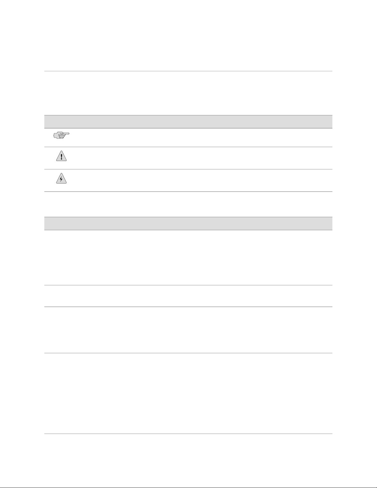
Figure 1: C2000, Front View
Concurrent SubscribersService Session LicensesModel
200,00050,000C2000
500,000100,000C4000
Figure 2: C2000, Rear View
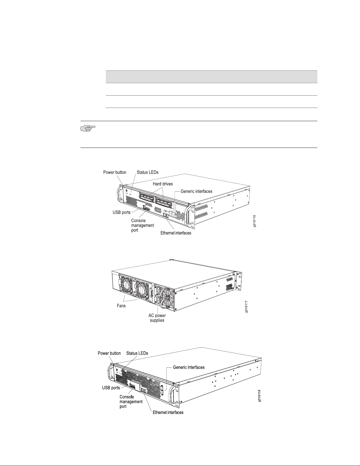
Figure 3: C4000, Front View
4 ■ C-series Platform Models
Page 19
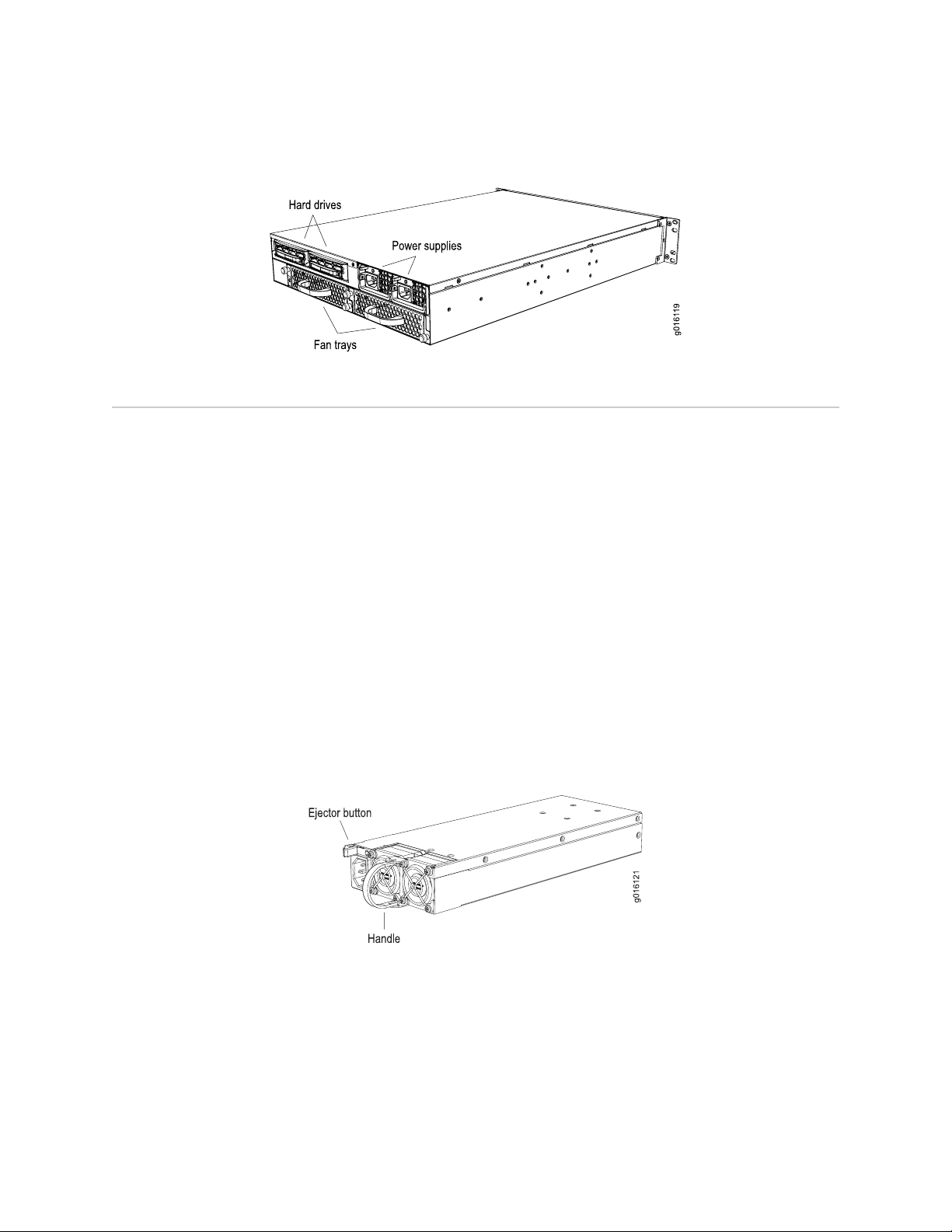
Figure 4: C4000, Rear View
C-series Model Components
The C2000 model and C4000 model contain the following components:
■ Internal memory
Chapter 1: C-series Platform Overview
■ CPU
■ Hard drive—Each model has two hot-swappable, redundant drives in a redundant
array of independent disks (RAID) 1 (mirror) configuration. The C2000 model
has two hard drives located in the front, and the C4000 model has two hard
drives located in the rear.
■ Fans—The C2000 model has two hot-swappable fans located in the rear. The
C4000 model has two hot-swappable fan trays located in the rear. Each fan tray
contains three fans.
■ Power supply—Each model has two hot-swappable, redundant AC-power supplies
located in the rear. Depending on the model, each power supply module has
either two (C2000 model) or one (C4000 model) associated fan.
Figure 5: C2000 Power Supply
C-series Model Components ■ 5
Page 20
C2000 and C4000 1.0.x Hardware Guide
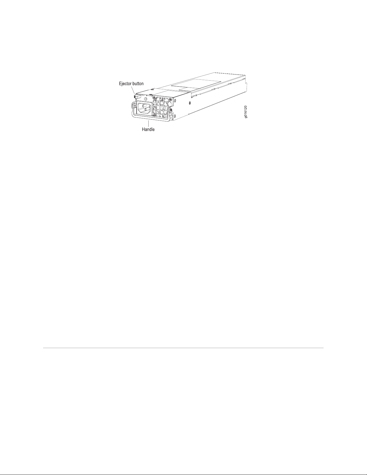
Figure 6: C4000 Power Supply
■ Console management port—Each model has one RS-232 port that accepts a
DB-9 (female) connector for direct CLI access from a console terminal.
■ USB port—Each model has two ports that can be used for memory storage
devices.
■ Ethernet interfaces—Each model has two 10/100/1000Base-T Ethernet ports
(ETH0 and ETH1) that accept an RJ-45 (male) connector, providing an out-of-band
connection for LAN access through a Telnet session, SSH, or SNMP. ETH0 provides
access from a network that is behind a firewall. ETH1 provides access for
applications on an external network, such as the Internet.
■ Generic interfaces—Each model has two generic ports (ETH2 and ETH3) that
enable you to use standard connectors, such as small form-factor pluggable
transceivers (SFPs), to create fiber-optic or Gigabit Ethernet connections and
provide additional LAN connectivity.
■ Status LEDs—Each model has LEDs that provide information about hard drive,
power supply, and interface status.
■ USB storage device—Contains the latest system software, including the operating
system for the C-series platform. The device is read-only and should be used to
recover from a major software failure. See the SRC Release Notes for more
information about recovering from a software failure.
■ Rack-mount and rail kit.
Network Management Tools
You can use different management tools to configure the system to meet the specific
networking requirements.
CLI Management
The command-line interface (CLI) provides fully developed and automated
configuration and status functionality through a local RS-232 port, Telnet, or SSH
over any reachable network. For a full discussion of the CLI, see the SRC–PE CLI User
Guide.
6 ■ Network Management Tools
Page 21

SNMP MIB Management
The system offers a complete SNMP interface for configuration, status, and alarm
reporting. For more information, see SRC–PE Monitoring and Troubleshooting Guide.
Chapter 1: C-series Platform Overview
Network Management Tools ■ 7
Page 22

C2000 and C4000 1.0.x Hardware Guide
8 ■ Network Management Tools
Page 23

Part 2
Initial Installation
■ Unpacking and Inspecting the C-series Platform on page 11
■ Installing and Cabling the C-series Platform on page 13
■ Powering Up the C-series Platform on page 19
■ Setting the Initial Configuration on page 21
Initial Installation ■ 9
Page 24

C2000 and C4000 1.0.x Hardware Guide
10 ■ Initial Installation
Page 25

Chapter 2
Unpacking and Inspecting the C-series Platform
This chapter reviews shipping contents and unpacking procedures for the C-series
platform. It contains the following topics:
■ Before You Begin on page 11
■ Unpacking the Units on page 12
■ Inspecting System Components and Accessories on page 12
■ If You Detect or Suspect Damage on page 12
■ Contacting Juniper Networks on page 12
■ The Next Step on page 12
Before You Begin
Before you begin unpacking the item, be sure you have the following tools:
■ A No. 2 Phillips screwdriver
■ A utility knife
■ A mechanical lift, or at least one person to assist in lifting
Before You Begin ■ 11
Page 26

C2000 and C4000 1.0.x Hardware Guide
Unpacking the Units
The systems are delivered boxed. For your convenience, we recommend that you
unpack the system in the location where you want to install it.
WARNING: Three people are required to install the system in a rack: two to lift it
into position and one to screw it to the rack.
Inspecting System Components and Accessories
After you remove the equipment from the shipping containers:
■ Confirm the contents of each container.
■ Inspect all external surfaces and external connectors for visible signs of damage.
■ Inspect all accessories shipped with each unit.
■ Document any damage noted during your inspection.
■ Confirm that the system has the correct number and type of components for
your ordered configuration.
If You Detect or Suspect Damage
If you detect or suspect damage to any equipment:
■ Contact the shipper responsible for delivery, and formally report the damage.
■ Contact your Juniper Networks sales representative or reseller.
Contacting Juniper Networks
Please contact Juniper Networks at 1-888-314-JTAC (from the United States, Canada,
or Mexico) or 1-408-745-9500 (from elsewhere), or contact your sales representative
if you have any questions or concerns. See “Contacting Customer Support and Returning
Hardware” on page 53 for complete contact information.
The Next Step
12 ■ Unpacking the Units
■ To familiarize yourself with the electrical, environmental, and other guidelines
and requirements for installing the system, see Installation Guidelines and
Requirements on page 43.
■ If you are familiar with these guidelines and requirements, see Installing and
Cabling the C-series Platform on page 13.
Page 27

Chapter 3
Installing and Cabling the C-series Platform
This chapter describes how to install the C-series platform and attach cables. It
contains the following topics:
■ Before You Begin on page 13
■ Freestanding Installation on page 13
■ Rack-Mounted Installation on page 14
■ Cabling the System on page 15
■ The Next Step on page 18
Before You Begin
Before installing the system, be sure you:
■ Have a plan for installing the system that takes into consideration future
expansion.
■ Have the tools and accessories needed to complete the installation.
■ Read and understand the clearance requirements for the front and back of the
chassis for cable routing and other unit access. See Environmental
Requirements on page 44 for more information.
■ Read and understand the clearance requirements for the top and bottom of the
chassis to ensure adequate ventilation.
■ Prepare the equipment racks by measuring and marking space for each system
you plan to install.
Freestanding Installation
When installing the system on a table top or in any other freestanding mode, be sure
to leave enough space around the system for adequate ventilation. Position the
Before You Begin ■ 13
Page 28

C2000 and C4000 1.0.x Hardware Guide
system with easy access to the connections that it needs for power, local
communications, and remote communications.
WARNING: Two people are required to lift the system.
CAUTION: To prevent electrostatic damage to the system and its components, make
sure persons handling the system wear an antistatic device.
Rack-Mounted Installation
We recommend that you use a standard EIA distribution rack. See “Equipment Rack
Requirements” on page 46 for rack information.
Installation Guidelines
Before installing the systems in a rack, consider the following guidelines:
■ You can install several models in a single 7-ft. (2.1-m) rack. Installing multiple
systems in a single rack enables you to maximize your available space.
■ Install heavier systems on the bottom of the rack. Mount lighter systems higher
in the rack.
Preparing the Equipment Racks
Following your installation plan, use a tape measure and marking pen to measure
and mark space on each equipment rack for each system component. For horizontal
spacing follow Network Equipment Building System (NEBS) requirements.
Installing the System
To complete the installation of the system in a rack, you need:
■ A Phillips screwdriver
■ Eight 10-32 x 3/8 Phillips screws (provided) for each model to be installed
To install the system in the rack:
14 ■ Rack-Mounted Installation
Page 29

Cabling the System
Chapter 3: Installing and Cabling the C-series Platform
1. With one person standing on the left side of the chassis and another standing
on the right side, lift the unit into the rack.
2. Position the system in its designated location in the equipment rack. Make sure
the holes of the mounting brackets align evenly with the holes of the equipment
rack on both sides.
3. Starting at the bottom of the system, have the third person secure the system
in the equipment rack by using the 10-32 x 3/8 Phillips screws.
4. Connect the necessary cables.
Cabling the system requires the following main tasks:
1. Familiarize yourself with the ports, and ensure that you have the cables and
wires needed to complete each cabling procedure.
2. Read and understand all safety warnings. (See “Installation Guidelines and
Requirements” on page 43.)
3. Connect the system to the network and to a management console.
4. Connect the other interfaces to their appropriate network interface.
5. Connect the power cables from the power source to the system's power supply.
NOTE: We recommend that you use shielded cables where appropriate.
See “System Specifications” on page 35 for more information about system
specifications.
Cabling the Management Console
Before powering up the system, you must set up a management console. The console
enables you to communicate with your system during the power-up process and to
manage your system using the command-line interface (CLI).
When connecting a console directly to the system, use a cable appropriate for your
terminal connector. The cable must have a female DB-9 connector to attach to the
RS-232 port on the system.
Management Ports
The management section of the system has three ports for management access (see
Figure 7 and Figure 9):
Cabling the System ■ 15
Page 30

C2000 and C4000 1.0.x Hardware Guide
■ Two 10/100Base-T Ethernet ports—Each accepts an RJ-45 (male) connector,
providing an out-of-band connection for LAN access through a Telnet session,
SSH, or SNMP.
■ One RS-232 management port—Accepts a DB-9 (female) connector. This port
provides direct CLI access from a console terminal.
The management port is considered a data terminal equipment (DTE) interface.
Direct connection to a terminal or PC (which also has DTE interfaces) requires a
crossover cable.
See “Setting the Initial Configuration” on page 21 for more information about
management access.
Connecting to the Network
To connect the system to the network:
1. Insert an Ethernet cable (RJ-45) connector into the 10/100Base-T (RJ-45) port on
the system until it clicks into place.
2. Connect the other end of the cable to the appropriate Ethernet network for an
out-of-band connection.
Connecting to a Console Terminal
When you connect a console directly to the system, use a cable appropriate for your
terminal connector. The cable must have a female DB-9 connector to attach to the
RS-232 port on the system.
To connect the console:
1. Insert the female DB-9 connector into the RS-232 port, and tighten the screws.
2. Connect the other end of the cable to your terminal's serial port (VT100/ANSI).
Cabling Ethernet Interfaces
Port ETH0 and ETH1 on the C2000 model and the C4000 model accept RJ-45
10/100/1000Base-T Ethernet (copper) interfaces. Port ETH2 and port ETH3 on the
C2000 model and the C4000 model accept SFPs.
Cabling the System for Power
After you have correctly cabled the system, you can then attach the power cord. See
Figure 8 and Figure 10. See “System Specifications” on page 35 for the power
requirements for the system.
To cable the system for power:
1. Insert the power cord into the AC power IEC receptacle.
16 ■ Cabling the System
Page 31

Chapter 3: Installing and Cabling the C-series Platform
2. Insert the other end of the power cord into an appropriate AC power source.
NOTE: To provide redundancy, do not terminate Power A and Power B leads at the
same power source.
Figure 7: C2000, Front View
Figure 8: C2000, Rear View
Figure 9: C4000, Front View
Cabling the System ■ 17
Page 32

C2000 and C4000 1.0.x Hardware Guide
Figure 10: C4000, Rear View
The Next Step
After you finish installing and cabling the system:
■ See Powering Up the C-series Platform on page 19.
18 ■ The Next Step
Page 33

Chapter 4
Powering Up the C-series Platform
This chapter describes how to power up the C-series platform. It contains the following
topics:
■ Powering Up on page 19
■ Status LEDs on page 20
■ The Next Step on page 20
Powering Up
NOTE: In this procedure we assume that the system is already connected to a power
source.
For specifications of the electrical requirements for the system, see “System
Specifications” on page 35.
CAUTION: Evaluate the overall loading of the branch circuit before you install any
equipment into a rack.
To power up the system:
1. Verify that the power source is operational and turned on.
2. Inspect all grounding and power connections to the system.
3. Confirm that all connections are secure.
4. Push the PWR button.
5. Monitor the LEDs to verify that the system is booting properly.
When the prompt appears on the system console, you can log in and configure
the system.
See the “Setting the Initial Configuration” on page 21 and SRC–PE CLI User Guide for
more information.
Powering Up ■ 19
Page 34

C2000 and C4000 1.0.x Hardware Guide
Status LEDs
The LEDs listed in Table 5 on page 20 are used on both models.
Table 5: Model LEDs
ON to OFFOFF to ONLED ColorLED IndicatorLED Label
Power offPower onGreenPowerPWR
The Next Step
Hard driveHD
RedTemperatureTEMP
PS FAIL
failure
GreenEthernetTX/RX
See “Setting the Initial Configuration” on page 21.
Hard drive is
functioning
error exists; fan
failure
Ethernet link upGreenEthernetLINK
Blinks when
Ethernet traffic
on link
Hard drive
failure detected
Fan okayTemperature
Fan okayFailure detectedRedPower supply
Ethernet link
down
No Ethernet
traffic on link
20 ■ Status LEDs
Page 35

Chapter 5
Setting the Initial Configuration
This chapter discusses how to set up the C-series platform after powering it on. For
basic information on the management of the system, see the SRC–PE Getting Started
Guide.
This chapter contains the following topics:
■ Configuration Overview on page 21
■ Setting Up Management Access and Logging In on page 21
■ Configuring the Juniper Networks Database on page 22
■ Configuring Hostname and Domain Parameters on page 23
■ Configuring the System for Remote Access on page 24
■ Configuring the System to Accept SSH and Telnet Connections on page 25
■ Adding an Admin User Account on page 26
■ The Next Step on page 27
Configuration Overview
After powering on the system, there are six main steps required to get it ready to
work with:
1. Connect a management console to the system, configure it, and log in.
2. Configure the Juniper Networks Database.
3. Configure hostname and domain information.
4. Configure the system for remote access.
5. Configure the system to accept SSH and Telnet connections.
6. Add an Admin user account.
Setting Up Management Access and Logging In
Before you power up the system, you must set up a management console. (See
“Connecting to a Console Terminal” on page 16.)
Configuration Overview ■ 21
Page 36

C2000 and C4000 1.0.x Hardware Guide
You can monitor and manage the system through either of these methods:
■ Console terminal—Connect a console (PC, Macintosh, or UNIX workstation)
directly to the system's RS-232 serial port.
■ Remote console—Connect 10/100Base-T port (ETH0) to an Ethernet network,
and run SSH or Telnet from a remote console.
For initial access to the system, you need to physically connect your console directly
to the system's RS-232 port. Through this connection you use the SRC command-line
interface (CLI) to set the hostname and domain information. You can then access
the system remotely (for example, by means of SSH).
To communicate with the system, you must have a terminal emulation program
running on your PC or Macintosh. You can use any terminal emulation program,
such as HyperTerminal. A UNIX workstation can use the emulator TIP.
To log in to the system:
1. Start your terminal emulation program using the following settings:
■ Bits per second: 9600
■ Data bits: 8
■ Parity: None
■ Stop bits: 1
■ Flow control: none
2. Enter the username.
SRC-PE Release 7.0 [B.7.0.0-12]
localhost login:root
3. Enter the password.
localhost password:password
--- SRC CLI 7.0 build CLI.B.7.0.0.012
(c) 2005-2007 Juniper Networks Inc.
root@localhost>
You are now logged in as root user.
Configuring the Juniper Networks Database
Each C-series platform contains a Juniper Networks database. The database stores
SRC data, sample data, configuration information, and user profiles. You must enable
the Juniper Networks database the first time you power on the system. It can operate
as a standalone database or as a member of a community of Juniper Networks
databases.
22 ■ Configuring the Juniper Networks Database
Page 37

Chapter 5: Setting the Initial Configuration
NOTE: The Juniper Networks database must be running before you start configuring
the SRC software.
Typically, you run the database in standalone mode only in testing environments.
In standalone mode, the database does not communicate with other Juniper Networks
databases; there is no data distribution and no redundancy. In community mode,
databases distribute data changes among specified databases. When you have two
or more C-series platforms, enable the Juniper Networks database to run in community
mode, and assign a role to each database:
■ Primary role—A database that provides read and write access to client
applications. It replicates its data and distributes changes to any Juniper Networks
databases configured as neighbors.
■ Secondary role—A database that provides read access to client applications. If
client applications try to write data to this database, the database refers the client
to a primary database.
In the following example, a standalone database is enabled. For more information
about community mode, see SRC–PE Getting Starting Guide, Chapter 10, Managing
the Juniper Networks Database.
To enable a Juniper Networks database to run in standalone mode:
1. From configuration mode, access the configuration statement that configures
the Juniper Networks database.
user@host# edit system ldap server
2. Enable standalone mode.
[edit system ldap server]
user@host# set stand-alone
Configuring Hostname and Domain Parameters
To set hostname and domain parameters:
1. Enter configuration mode.
root@host> edit
2. Configure the hostname.
[edit]
root@host# set system host-name host-name
For example:
[edit]
root@host# set system host-name my-hostname
Configuring Hostname and Domain Parameters ■ 23
Page 38

C2000 and C4000 1.0.x Hardware Guide
3. Configure either a list of domain names to search, or create the domain name.
We recommend configuring a list of domain names to search.
To configure a list of domain names to search:
[edit]
root@host# set system domain-search [domain-name1, domain-name2, ...]
For example:
[edit]
root@host# set system domain-search [my-domain.juniper.net
domain.juniper2.net]
To configure the domain name:
[edit]
root@host# set system domain-name domain-name
For example:
[edit]
root@host# set system domain-name my-domain.juniper.net
Configuring the System for Remote Access
To allow remote access to the system, you must configure the generic interfaces.
You can specify an IP address with mask or a broadcast address with mask for an
interface. For more information, see SRC–PE Getting Starting Guide, Chapter 7,
Configuring Remote Access to an SRC Platform.
To configure the generic interfaces:
1. From configuration mode, access the configuration statement that configures
the interface.
user@host# edit interfaces eth0
2. Specify the unit, family, and IP address for the interface.
[edit interfaces eth0]
user@host# set unit number family inet address address
For example, to configure an interface with only an IP address:
[edit interfaces eth0]
user@host# set unit 0 family inet address 192.2.0.10/24
3. (Optional) Specify the broadcast address for the interface.
[edit interfaces eth0]
user@host# set unit number family inet broadcast broadcast
For example, to configure an interface with only a broadcast address:
24 ■ Configuring the System for Remote Access
Page 39

Chapter 5: Setting the Initial Configuration
[edit interfaces eth0]
user@host# set unit 0 family inet broadcast 192.2.0.255
4. Verify the interface configuration.
[edit interfaces eth0]
user@host# show
unit 0 {
family {
inet {
broadcast 192.2.0.255;
}
}
}
Configuring the System to Accept SSH and Telnet Connections
You can enable SSH and Telnet to let users who have the appropriate privileges
connect to the system. For security reasons, we recommend that you do not allow
remote users to access the CLI as root. The system does not allow root access over
a Telnet connection. For more information, see SRC–PE Getting Starting Guide, Chapter
7, Configuring Remote Access to a C–series Platform.
To configure the system to accept SSH connections:
1.
From configuration mode, access the [edit system services ssh] hierarchy level.
2. (Optional) Specify whether or not to allow root login through SSH.
[edit system services ssh]
user@host> set root-login (allow | deny | deny-password)
where:
■
allow— Allow users to log in to the C-series platform as root through SSH.
■
deny— Disable users from logging in to the system as root through SSH.
■
deny-password— Allow users to log in to the system as root through SSH
when the authentication method (for example, RSA authentication) does not
require a password. (Default)
Configuring the System to Accept SSH and Telnet Connections ■ 25
Page 40

C2000 and C4000 1.0.x Hardware Guide
To configure the system to accept Telnet connections:
■ In edit mode, type the following command.
[edit]
user@host# set system services telnet
Adding an Admin User Account
Although root access is used for initial configuration of the system, user accounts are
used to enter commands and statements at the CLI. Therefore, you must set up an
admin account to allow further configuration. You can use a built-in class, such as
super-user.
To configure an account for an administrative user:
1. Create an account for an administrative user.
[edit]
user@host # edit system login user user
For example:
[edit]
user@host # edit system login user myadmin
2. Set the class for the administrative user to the login class that you created.
[edit system login user myadmin]
user@host # set class class
For example:
[edit system login user myadmin]
user@host # set class super-user
3. Specify the name of the administrative user.
[edit system login user myadmin]
user@host # set full-name “John Doe”
4. Set the CLI editing level to expert.
[edit system login user myadmin]
user@host# set level expert
5. (Optional) Specify that a space be used for command completion.
[edit system login user myadmin]
user@host # set complete-on-space on
6. Verify that the configuration for the administrative user is correct.
[edit system login user myadmin]
26 ■ Adding an Admin User Account
Page 41

The Next Step
Chapter 5: Setting the Initial Configuration
user@host# show
class super-user;
full-name "John Doe";
uid 506;
gid 100;
level expert;
complete-on-space on;
7. Set the password of the user.
[edit]
user@host# edit system login user myadmin authentication
[edit system login user myadmin authentication]
user@host# set plain-text-password
See “Maintaining the System” on page 31.
The Next Step ■ 27
Page 42

C2000 and C4000 1.0.x Hardware Guide
28 ■ The Next Step
Page 43

Part 3
Hardware Maintenance Procedures and Specifications
■ Maintaining the System on page 31
■ System Specifications on page 35
■ Managing RAID Disks on a C-series Platform on page 39
■ Installation Guidelines and Requirements on page 43
■ Contacting Customer Support and Returning Hardware on page 53
■ Declaration of Conformity on page 57
Hardware Maintenance Procedures and Specifications ■ 29
Page 44

C2000 and C4000 1.0.x Hardware Guide
30 ■ Hardware Maintenance Procedures and Specifications
Page 45

Chapter 6
Maintaining the System
This chapter lists the tools, items, and steps needed for installing and uninstalling
components. Other maintenance procedures must be performed by an authorized
Juniper Networks technician.
This chapter contains the following sections:
■ Required Tools and Items on page 31
■ Storing Modules and Components on page 32
■ Cleaning the System on page 32
■ Removing and Installing a Fan on page 32
■ Removing and Installing a Power Supply Module on page 33
■ Removing and Installing a Hard Drive on page 34
Required Tools and Items
You need the following tools and other items to replace components:
■ Flathead and Phillips screwdrivers
■ Insulated adjustable wrench
■ Antistatic wrist strap
■ Antistatic bags (or other protective packaging to hold components)
■ Plastic boots or other protective covers for fiber-optic connectors
Required Tools and Items ■ 31
Page 46

C2000 and C4000 1.0.x Hardware Guide
Storing Modules and Components
Retain the packaging in which a component was shipped, and use this packaging to
store the item.
CAUTION: Failure to store electronic components correctly can lead to damage of
these items.
Follow these guidelines for storing components:
■ Store each component in a separate antistatic bag.
■ Store components in an antistatic plastic container. Some of these containers
can accommodate several components in separate compartments.
■ Do not store multiple components in an antistatic bag or container where they
■ (Optional) Store the item in its antistatic bag or container within the protective
Cleaning the System
Clean the system with a dry cloth every few weeks to prevent excessive dust
accumulation. This cleaning helps to maintain the efficiency of the cooling system
and to prevent damage to electronic components.
WARNING: Do not insert any metal object, such as a screwdriver, or place your hand
into an open slot when the system is on. Remove jewelry (including rings, necklaces,
and watches) before working on equipment that is connected to power lines. These
actions prevent electric shock and serious burns.
CAUTION: When cleaning the system, wear an antistatic device. This action helps
to protect components from damage by electrostatic discharge.
can touch other items.
packaging or padded box that the item was shipped in.
Removing and Installing a Fan
Both C-series models have two cooling fans that provide forced air cooling for
components in the system. Each fan is hot-swappable; you can replace it without
powering down the system. You can monitor fan status by observing the TEMP LED.
32 ■ Storing Modules and Components
Page 47

Chapter 6: Maintaining the System
NOTE: If the red TEMP LED is illuminated, either a critical or noncritical failure exists.
CAUTION: If the TEMP LED is illuminated and none of the fans is spinning, quickly
power down the system until a new set of fans is available. Operating a system with
inadequate air circulation can damage the components.
To remove a fan:
1. Unlock or loosen the fan from the system.
■ For the C2000 model, press the locking tab and rotate the fan away from
the system.
■ For the C4000 model, loosen the thumb screw in the top-left and lower-right
of the fan.
2. Pull the fan out and remove it from the system.
Use two hands to hold the fan after it comes out of the chassis.
WARNING: Do not place your fingers near the fans when removing the unit. The
blades might still be moving.
CAUTION: Do not use the fan tray handle to carry the fan. Use the handle only to
push the tray into the chassis or pull it out.
To install a fan, reverse the steps taken to remove the fan.
Removing and Installing a Power Supply Module
NOTE: If your system is powered on, see the SRC–PE CLI User Guide, Chapter 5, Using
CLI Operational Commands to Monitor the SRC Software for commands to run before
performing these steps.
To remove a power supply module:
1. Unplug the power cord.
Removing and Installing a Power Supply Module ■ 33
Page 48

C2000 and C4000 1.0.x Hardware Guide
2. Slide the locking tab (ejector button) to the left to release the module. See
Figure 11 and Figure 12.
3. Hold the tab to the left, and using the handle, slowly pull the power supply module
out.
To install a power supply module:
1. Hold the locking tab (ejector button) to the left, and slowly slide the module into
the chassis until it clicks into place.
2. Insert the power cord into the AC power IEC receptacle.
Figure 11: C2000 Power Supply
Figure 12: C4000 Power Supply
Removing and Installing a Hard Drive
NOTE: If your system is powered on, see the SRC–PE Getting Started User Guide for
commands to run before performing these steps.
To remove a hard drive:
1. Slide the locking tab in the bottom-right corner to the right to release the hard
drive.
2. Hold the tab to the right and slowly pull the unit out.
To install a hard drive, hold the locking tab to the right and slowly slide the unit into
the chassis until it clicks into place.
34 ■ Removing and Installing a Hard Drive
Page 49

Chapter 7
System Specifications
This chapter lists the system specifications, requirements, and certifications for the
system. Topics include:
■ C2000 Model Specifications on page 35
■ C4000 Model Specifications on page 36
C2000 Model Specifications
Table 6: C2000 Model Specifications
SpecificationCategory
Weight
Dimensions
Environmental Requirements
Temperature
Relative humidity
Heat Dissipation
AC Input
Space Requirements
33 lb (15 kg)
3.5 (H) x 16.7 (W) x 16.2 (D) inches
8.89 (H) x 42.42 (W) x 41.15 (D) cm
Operating: 50° to 104° F (10° to 40° C)
■
Storage: –40° to 158° F (–40° ˚ to 70° C)
■
Operating: 8% to 90% (noncondensing)
■
Storage: 5% to 95% (noncondensing)
■
500 W, 1706 BTU/hour maximum
100-240 VAC @ –5 APower required
50-60 HzAC line frequency
500 WPower
3 feet (90 cm) behind system or rack.
■
Do not block air vents on front or back of the system.
■
Safety Agency Certification
■
Pending
C2000 Model Specifications ■ 35
Page 50

C2000 and C4000 1.0.x Hardware Guide
Table 6: C2000 Model Specifications (continued)
SpecificationCategory
Airflow
Electromagnetic Emissions Agency Certification
■
■
■
C4000 Model Specifications
Table 7: C4000 Model Specifications
Air intake occurs in the front of the system.
Air is exhausted out of the rear of the system.
Pending
SpecificationCategory
Weight
Dimensions
Environmental Requirements
Temperature
Relative humidity
Heat Dissipation
AC Input
48 lb (22 kg)
3.5 (H) x 16.7 (W) x 24 (D) inches
8.89 (H) x 42.42 (W) x 60.96 (D) cm
Operating: 50° to 104° F (10° to 40° C)
■
Storage: –40° to 158° F (–40° ˚ to 70° C)
■
Operating: 8% to 90% (noncondensing)
■
Storage: 5% to 95% (noncondensing)
■
–40° ˚ to 158° F (–40° ˚ to 70° C), 95% relative humidityAmbient storage temperature
5% to 95% (noncondensing)Ambient storage humidity
700 W, 2389 BTU/hour maximum
100-240 VAC @ –5 APower required
50-60 HzAC line frequency
700 WPower
Space Requirements
Airflow
Safety Agency Certification
36 ■ C4000 Model Specifications
3 feet (90 cm) behind system or rack.
■
Do not block air vents on or back of the system.
■
Air intake occurs in the front of the system.
■
Air is exhausted out of the rear of the system.
■
Pending
■
Page 51

Table 7: C4000 Model Specifications (continued)
Electromagnetic Emissions Agency Certification
SpecificationCategory
■
Chapter 7: System Specifications
Pending
C4000 Model Specifications ■ 37
Page 52

C2000 and C4000 1.0.x Hardware Guide
38 ■ C4000 Model Specifications
Page 53

Chapter 8
Managing RAID Disks on a C-series Platform
This chapter describes how to manage and view status information for RAID disks
on a C-series platform. Topics include:
■ C-series Platform Data Storage on page 39
■ Managing Disks in a C-series Platform on page 40
C-series Platform Data Storage
A C-series platform provides data redundancy by supplying two hard drives (or disks)
in a redundant array of independent disks (RAID). Both disks are configured as a
RAID-1 mirror; this means that data is concurrently written to both disks. If one disk
becomes inoperable, the remaining disk continues to be active, which allows the
C-series platform to continue to function.
When you replace a faulty disk and initialize it, or disable and then enable a disk,
the RAID controller copies all the data from the active disk to the enabled or initialized
disk and establishes mirroring for the two disks.
The location of the disk mount for the disks depends on the model of the C-series
platform:
■ C2000 system—Front of chassis
■ C4000 system—Back of chassis
When you access the disks in the disk mount:
■ Disk 0 is to the left.
■ Disk 1 is to the right.
You can also use the request disk identify command to make the LED for a specified
disk blink to verify which disk is disk 0 and which is disk 1.
C-series Platform Data Storage ■ 39
Page 54

C2000 and C4000 1.0.x Hardware Guide
Managing Disks in a C-series Platform
The SRC CLI provides commands to let you monitor disk status, replace faulty disks,
and reinitialize disks in the system.
Replacing a Disk
If a disk in the C-series platform fails, you can replace it while the other disk remains
active.
To replace a disk:
1. Disable the disk.
user@host> request disk disable device 0 | 1
2. Remove the disk from the system.
3. Insert a new disk.
4. Enable the disk.
user@host> request disk enable device 0 | 1
5. Initialize the new disk.
user@host> request disk initialize device 0 | 1
The command generates data on the disk that enables the disk controller to
manage the disk. The disk controller copies data from the other disk and
establishes mirroring between the two disks.
6. Verify that the disk is initialized.
user@host> show disk status
C:ID:L Device Type Blocks Bytes/Block Usage Shared Rate
------ -------------- --------- ----------- ---------------- ------ ----
0:00:0 Disk 145226112 512 Initialized NO 150
0:01:0 Disk 145226112 512 Initialized NO 150
Smart Method of Enable
Capable Informational Exception Performance Error
C:ID:L Device Exceptions(MRIE) Control Enabled Count
------ ------- ---------------- --------- ----------- ------
0:00:0 Y 6 Y N 0
0:01:0 Y 6 Y N 0
40 ■ Managing Disks in a C-series Platform
Page 55

Controller Tasks
TaskId Function Done% Container State Specific1 Specific2
------ -------- ------- --------- ----- --------- --------100 Rebuild 0.3% 0 RUN 00000000 00000000
Reinitializing an Active Disk
You can reinitialize a disk that is already active in a C-series platform.
To reinitialize a disk:
■ Initialize the disk.
Chapter 8: Managing RAID Disks on a C-series Platform
user@host> request disk initialize device 0 | 1 force
The command generates data on the disk that enables the disk controller to
manage the disk. The disk controller copies data from the other disk and
establishes mirroring between the two disks.
Viewing Information About Disks on a C-series Platform
To view information about disks in the C-series platform:
■ Enter the show disk status command.
user@host> show disk status
C:ID:L Device Type Blocks Bytes/Block Usage Shared Rate
------ -------------- --------- ----------- ---------------- ------ ----
0:00:0 Disk 145226112 512 Initialized NO 150
0:01:0 Disk 145226112 512 Initialized NO 150
Smart Method of Enable
Capable Informational Exception Performance Error
C:ID:L Device Exceptions(MRIE) Control Enabled Count
------ ------- ---------------- --------- ----------- ------
0:00:0 Y 6 Y N 0
0:01:0 Y 6 Y N 0
Managing Disks in a C-series Platform ■ 41
Page 56

C2000 and C4000 1.0.x Hardware Guide
Controller Tasks
TaskId Function Done% Container State Specific1 Specific2
------ -------- ------- --------- ----- --------- --------No tasks currently running on the controller
Table 8: show disk status Output Fields
Field DescriptionField Name
C indicates the channel number, ID the device ID, and L the device logical numberC:ID:L
Type of device; diskDevice Type
Number of blocks available on the diskBlocks
Usage
Smart Capable Device
(MIE)
Number of bytes for each blockBytes/Block
Status of disk:
Detached—Not available for use
■
Initialized—Prepared for use with arrays
■
Not initialized—Not prepared for use with arrays
■
Offline—Present at system boot, but the disk was removed or failed
■
Unowned—The controller does not control the disk
■
Whether or not the disk is on a shared channelShared
Disk speed in megabytes per secondRate
Whether or not the device is enabled for Specifies if Self-Monitoring, Analysis and
Reporting Technology (SMART)
List of MIE exceptionsMethods of Informational Exceptions
Whether or not SMART exception reporting is enabledEnable Exception Control
Whether or not performance is enabledPerformance Enabled
Number of errors that SMART found on the diskError Count
Controller Tasks
The No tasks currently running on controller message indicates that no tasks are
running, including initialization.
42 ■ Managing Disks in a C-series Platform
Page 57

Chapter 9
Installation Guidelines and Requirements
This chapter reviews preinstallation considerations such as electrical, environmental,
and safety compliances for the C-series platforms. For complete system specifications,
see “System Specifications” on page 35.
This chapter contains the following topics:
■ Your Preinstallation Responsibilities on page 43
■ Environmental Requirements on page 44
■ Regulatory Compliances on page 44
■ Safety Guidelines on page 45
■ Equipment Rack Requirements on page 46
■ Cabling Recommendations on page 47
■ Product Reclamation and Recycling Program on page 48
■ Hardware Compliance on page 49
Your Preinstallation Responsibilities
Complete the following tasks before installing the system:
■ Verify that the electrical supply meets all AC and DC power requirements. See
System Specifications on page 35.
■ Verify that the site meets all environment specifications. See “Environmental
Requirements” on page 44 and “System Specifications” on page 35.
■ Verify that the cables you plan to use meet the specifications, and review the
cabling recommendations. See Cabling Recommendations on page 47.
■ Verify the operation of all telephone circuits, digital services, and T1 facilities
required for installation.
■ Ensure that all IP requirements are met, such as IP addresses, subnet masks,
and any specific routing protocol information.
Your Preinstallation Responsibilities ■ 43
Page 58

C2000 and C4000 1.0.x Hardware Guide
Environmental Requirements
See “System Specifications” on page 35 for complete environmental specifications.
Choose a location for the system that is dry, relatively dust free, well ventilated, and
air conditioned. If you install equipment in a rack, be sure that the floor is capable
of supporting the combined weight of the rack and the installed equipment. Place
the system in a location with sufficient access to power and network cables.
Like other network devices, the system generates a significant amount of heat. You
must provide a balanced environment so that the system performs properly and
safely. See “System Specifications” on page 35 for acceptable ranges of temperature
and humidity.
Be sure to allow enough space around the system for adequate ventilation. Inadequate
ventilation can cause the system to overheat.
CAUTION: Do not block the air vents on the system. Otherwise, the system might
overheat.
Regulatory Compliances
See “System Specifications” on page 35 for a complete list of regulatory compliance
requirements, including safety, EMC, and telecommunications.
44 ■ Environmental Requirements
Page 59

Safety Guidelines
Chapter 9: Installation Guidelines and Requirements
For your safety, before installing the system, review all safety warnings in this topic.
WARNING: The recommended maximum ambient temperature is 40˚° C (104° F).
For safe operation take into consideration the internal temperature within the rack.
WARNING: Install equipment in the rack from the bottom upward. Doing this helps
maintain the stability of the rack and reduces the chance of the rack tipping over.
WARNING: Do not insert any metal object, such as a screwdriver, into the system.
Doing so can cause electric shock and serious burns.
WARNING: Three people are required to install the system in a rack: two to lift the
system into position and one to screw it to the rack.
WARNING: Connect the system or rack to ground (earth), and ensure that a reliable
grounding path is maintained in the rack.
WARNING: Do not work on the system or connect or disconnect cables during
lightning activity.
WARNING: Be sure that circuit breakers for the power source are in the OFF position
before attaching power cables.
Safety Guidelines ■ 45
Page 60

C2000 and C4000 1.0.x Hardware Guide
WARNING: Before servicing the system, turn off the power.
WARNING: Remove jewelry (including rings, necklaces, and watches) before working
on equipment that is connected to power lines. Metal objects heat up when connected
to power and ground and can cause serious burns or become welded to the terminals.
CAUTION: Evaluate the overall loading of the branch circuit before you install any
equipment into a rack.
Equipment Rack Requirements
When allocating equipment rack space, consider the following:
■ Type of equipment racks recommended for the system
■ Number of equipment racks required to hold your current system configuration
■ Future expansion
Make sure that your distribution rack meets basic mechanical and space requirements
and complies with conventional standards. In the United States, use the EIA-310-D
Cabinets, Racks, Panels, and Associated Equipment, September 1992 standard.
Mechanical Requirements
Follow these mechanical requirements for your rack:
■ Select from the following rack options:
■ Two-post rack—A freestanding enclosed cabinet with two mounting posts
in the front
■ Telco-type rack—Two adjacent mounting posts that you must secure to the
floor or an overhead structure
■ Four-post rack—A freestanding open rack, either open or closed
■ The rack must have at least two mounting posts.
46 ■ Equipment Rack Requirements
Page 61

■ The distance between the mounting holes in the two posts must be 18.31 inches
■ An optional mounting kit is available for midchassis mounting. Contact your
Space Requirements
If you use an enclosed rack for the system, ensure that there is a minimum of 3
inches of clearance between the inner side wall and the system. This clearance space
ensures adequate air flow.
Proper Rack Installation
To confirm proper equipment rack installation, verify the following:
■ Racks are installed and electrically grounded according to manufacturer
Chapter 9: Installation Guidelines and Requirements
±.063 inch, as specified in EIA-310-D.
Juniper Networks sales representative for more information.
instructions.
■ Equipment racks are anchored to the floor and, when possible, anchored to the
ceiling as well.
■ Equipment rack installations comply with applicable local, state, and national
codes.
Cabling Recommendations
Comply with the following recommendations:
■ Use only shielded cables.
■ Ensure that cable distance and rate limits meet IEEE-recommended maximum
distances and speeds for signaling purposes. For information about attenuation
and power loss in optical fiber cables see:
■ ANSI T1.646a-1997 Telecommunications – Broadband ISDN - Physical Layer
Specification for User-Network Interfaces Including DS1/ATM (1997)
■ ANSI T1.646-1995 Telecommunications – Broadband ISDN - Physical Layer
Specification for User-Network Interfaces Including DS1/ATM (1995)
■ Ensure that power cables deliver sufficient power to the system.
■ Attach laser fiber connectors only to Class 1 laser devices in accordance with
IEC 60825-1, Safety of Laser Products - Part 1.
■ Route cables so that they do not restrict ventilation or airflow.
Cabling Recommendations ■ 47
Page 62

C2000 and C4000 1.0.x Hardware Guide
■ Route cables so that modules and field-replaceable units are easily accessible.
■ Route cables in a logical direction to prevent loss of connectivity to other
equipment in the rack, to associated equipment in adjacent racks, or to the
backbone network.
For additional cable recommendations, consult the document GR-63–CORE: Network
Equipment Building System (NEBS) Requirements: Physical Protection, Issue 2, April
2002.
Product Reclamation and Recycling Program
Juniper Networks is committed to environmentally responsible behavior. As part of
this commitment, we continually work to comply with environmental standards such
as the European Union’s Waste Electrical and Electronic Equipment (WEEE) Directive
and Restriction of Hazardous Substances (RoHS) Directive.
These directives and other similar regulations from countries outside the European
Union regulate electronic waste management and the reduction or elimination of
specific hazardous materials in electronic products. The WEEE Directive requires
electrical and electronics manufacturers to provide mechanisms for the recycling
and reuse of their products. The RoHS Directive restricts the use of certain substances
that are commonly found in electronic products today. Restricted substances include
heavy metals, including lead, and polybrominated materials. The RoHS Directive,
with some exemptions, applies to all electrical and electronic equipment.
In accordance with Article 11(2) of Directive 2002/96/EC (WEEE), products put on
the market after 13 August 2005 are marked with the following symbol or include
it in their documentation: a crossed-out wheeled waste bin with a bar beneath.
Juniper Networks provides recycling support for our equipment worldwide to comply
with the WEEE Directive. For recycling information, go to
http://www.juniper.net/environmental, and indicate the type of Juniper Networks
equipment that you wish to dispose of and the country where it is currently located,
or contact your Juniper Networks account representative.
Products returned through our reclamation process are recycled, recovered, or
disposed of in a responsible manner. Our packaging is designed to be recycled and
should be handled in accordance with your local recycling policies.
48 ■ Product Reclamation and Recycling Program
Page 63

Hardware Compliance
C–series platforms meet the hardware compliance requirements in this topic.
Federal Communications Commission (FCC) Statement
This equipment has been tested and found to comply with the limits for a Class A
digital device, pursuant to Part 15 of the FCC Rules. These limits are designed to
provide reasonable protection against harmful interference when the equipment is
operated in a commercial environment. This equipment generates, uses, and can
radiate radio frequency energy and, if not installed and used in accordance with the
instruction manual, may cause harmful interference to radio communications.
Operation of this equipment in a residential area is likely to cause harmful interference
in which case the user will be required to correct the interference at his own expense.
This equipment is designed for use with properly shielded and terminated cables.
Refer to the installation sections of this manual before operation.
Chapter 9: Installation Guidelines and Requirements
Reference: CFR 47, Part 15J, Sect 15.105 April 18, 1989
Caution: Changes or Modifications to this equipment not expressly approved by the
party responsible for compliance could void the user's authority to operate the
equipment.
FCC Requirements for Consumer Products
This equipment complies with FCC rules, Part 68. On the back side of this equipment
is a label that contains, among other information, the FCC Registration Number and
Ringer Equivalence Number (REN) for this equipment. If requested, provide this
information to your telephone company.
If this equipment causes harm to the telephone network, the Telephone Company
may discontinue your service temporarily. If possible, they will notify you in advance.
But if advance notice isn't practical, you will be notified as soon as possible. You will
be advised of your right to file a complaint with the FCC.
Your telephone company may make changes in its facilities, equipment, operations,
or procedures that could affect the proper operation of your equipment. If they do,
you will be given advance notice so as to give you an opportunity to maintain
uninterrupted service.
If you experience trouble with this equipment, please contact the manufacturer for
warranty/repair information. The telephone company may ask that you disconnect
this equipment from the network until the problem has been corrected or until you
are sure that the equipment is not malfunctioning.
Food and Drug Administration, Center for Devices and Radiological Health
This equipment complies with 21 CFR 1040.10 and 1040.11 for the safe use of lasers.
Hardware Compliance ■ 49
Page 64

C2000 and C4000 1.0.x Hardware Guide
Canadian Department of Communications Radio Interference Regulations
This Class B (or Class A, if so indicated on the registration label) digital apparatus
meets the requirements of the Canadian Interference-Causing Equipment Regulations.
Réglement sur le brouillage radioélectrique du ministère des communications
Cet appareil numérique de la Classe B (ou Classe A, si ainsi indiqué sur l'étiquette
d'enregistration) respecte toutes les exigences du Reglement sur le Materiel Brouilleur
du Canada.
Industry Canada Notice CS-03
The Industry Canada label identifies certified equipment. This certification means
that the equipment meets certain telecommunications network protective, operation
and safety requirements as prescribed in the appropriate Terminal Equipment
Technical Requirements document(s). The Department does not guarantee the
equipment will operate to the user's satisfaction. Before installing this equipment,
users should ensure that it is permissible to be connected to the facilities of the local
telecommunications company. The equipment must also be installed using and
acceptable method of connection. The customer should be aware that compliance
with the above conditions may not prevent degradation of service in some situations.
Repairs to certified equipment should be coordinated by a representative designated
by the supplier. Any repairs or alterations made by the user to this equipment, or
equipment malfunctions, may give the telecommunications company cause to request
the user to disconnect the equipment.
Users should ensure for their own protection that the electrical ground connections
of the power utility, telephone lines and internal metallic water pipe system, if present,
are connected together. This precaution may be particularly important in rural areas.
Caution: Users should not attempt to make such connections themselves, but should
contact the appropriate electric inspection authority, or electrician, as appropriate.
Notice: The Ringer Equivalence Number (REN) assigned to each terminal device
provides an indication of the maximum number of terminals allowed to be connected
to a telephone interface. The termination on an interface may consist of any
combination of devices subject only to the requirement that the sum of the Ringer
Equivalence Numbers of all the devices does not exceed 5.
Avis CS-03 d'Industrie Canada
L'étiquette du ministère des Communications du Canada indique que l'appareillage
est certifié, c'est-à-dire qu'il respecte certaines exigences de sécurité et de
fonctionnement visant les réseaux de télécommunications. Le ministère ne garantit
pas que l'appareillage fonctionnera à la satisfaction de l'utilisateur. Avant d'installer
l'appareillage, s'assurer qu'il peut être branché aux installations du service de
télécommunications local. L'appareillage doit aussi être raccordé selon des méthodes
acceptées. Le client doit toutefois prendre note qu'une telle installation n'assure pas
un service parfait en tout temps.
50 ■ Hardware Compliance
Page 65

Chapter 9: Installation Guidelines and Requirements
Les réparations de l'appareillage certifié devraient être confiées à un service
d'entretien canadien désigné par lefournisseur. En cas de réparation ou de
modification effectuées par l'utilisateur ou de mauvais fonctionnement
del'appareillage, le service de télécommunications peut demander le débranchment
de l'appareillage.
Pour leur propre sécurité, les utilisateurs devraient s'assurer que les mises à la terre
des lignes de distribution d'électricité, des lignes téléphoniques et de la tuyauterie
métallique interne sont raccordées ensemble. Cette mesure de sécurité est
particulièrement importante en milieu rural.
Attention: Les utilisateurs ne doivent pas procéder à ces raccordements eux-mêmes
mais doivent plutôt faire appel aux pouvoirs de réglementation en cause ou à un
électricien, selon le cas.
Avis: Veuillez prendre note que pour tout appareillage supportant des lignes de type
“loopstart,” l'indice d'équivalence de la sonnerie (IES) assigné à chaque dispositif
terminal indique le nombre maximal de terminaux qui peuvent être raccordés à une
interface. La terminaison d'une interface téléphonique peut consister en une
combinaison de quelques dispositifs, à la seule condition que la somme d'indices
d'équivalence de la sonnerie de tous les dispositifs n'excède pas 5. Le REN figure
sur l'étiquette “FCC Rules Part 68” située sur le support du module ou à l'arrière de
l'unité.
D.O.C. Explanatory Notes: Equipment Attachment Limitations
The Canadian Department of Communications label identifies certified equipment.
This certification meets certain telecommunication network protective, operational
and safety requirements. The department does not guarantee the equipment will
operate to the users satisfaction.
Before installing the equipment, users should ensure that it is permissible to be
connected to the facilities of the local telecommunications company. The equipment
must also be installed using an acceptable method of connection. In some cases, the
company's inside wiring associated with a single line individual service may be
extended by means of a certified connector assembly (telephone extension cord).
The customer should be aware that compliance with the above condition may not
prevent degradation of service in some situations.
Repairs to certified equipment should be made by an authorized Canadian
maintenance facility designated by the supplier. Any repairs or alterations made by
the user to this equipment, or equipment malfunctions, may give the
telecommunications company cause to request the user to disconnect the equipment.
Users should ensure for their own protection that the electrical ground connections
of the power utility, telephone lines and internal metallic water pipe system, if present,
are connected together. This precaution may be particularly important in rural areas.
Caution: Users should not attempt to make such connections themselves, but should
contact the appropriate electrical inspection authority, or electrician, as appropriate.
Hardware Compliance ■ 51
Page 66

C2000 and C4000 1.0.x Hardware Guide
Notes explicatives du ministère des Communications: limites visant les accessoires
L'étiquette du ministère des Communications du Canada indique que l'appareillage
est certifié, c'est-à-dire qu'il respecte certaines exigences de sécurité et de
fonctionnement visant les réseaux de télécommunications. Le ministère ne garantit
pas que l'appareillage fonctionnera à la satisfaction de l'utilisateur.
Avant d'installer l'appareillage, s'assurer qu'il peut être branché aux installations du
service de télécommunications local. L'appareillage doit aussi être raccordé selon
des méthodes acceptées. Dans certains cas, le câblage interne du service de
télécommunications utilisé pour une ligne individuelle peut être allongé au moyen
d'un connecteur certifié (prolongateur téléphonique). Le client doit toutefois prendre
note qu'une telle installation n'assure pas un service parfait en tout temps.
Les réparations de l'appareillage certifié devraient être confiées à un service
d'entretien canadien désigné par le fournisseur. En cas de réparation ou de
modification effectuées par l'utilisateur ou de mauvais fonctionnement de
l'appareillage, le service de télécommunications peut demander le débranchment
de l'appareillage.
Pour leur propre sécurité, les utilisateurs devraient s'assurer que les mises à la terre
des lignes de distribution d'électricité, des lignes téléphoniques et de la tuyauterie
métallique interne sont raccordées ensemble. Cette mesure de sécurité est
particulièrement importante en milieu rural.
Attention: Les utilisateurs ne doivent pas procéder à ces raccordements eux-mêmes
mais doivent plutôt faire appel aux pouvoirs de réglementation en cause ou à un
électricien, selon le cas.
EC Declaration of Conformity
The EC Declaration of Conformity is available in “Declaration of
Conformity” on page 57.
Voluntary Control Council for Interference (VCCI) Statement for Japan
The preceding translates as:
This is a Class A product. In a domestic environment this product may cause radio
interference in which case the user may be required to take adequate measures.
VCCI-A
52 ■ Hardware Compliance
Page 67

Chapter 10
Contacting Customer Support and Returning Hardware
See the Juniper Networks Web site for complete customer service information:
■
http://www.juniper.net/support/guidelines.html
This chapter contains the following topics:
■ Contacting Customer Support on page 53
■ Return Procedure on page 53
■ Locating Component Serial Numbers on page 54
■ Information You Might Need to Supply to JTAC on page 54
■ Tools and Parts Required on page 55
■ Returning Products for Repair or Replacement on page 55
Contacting Customer Support
For your convenience, we provide multiple options for requesting and receiving
technical support from the Juniper Networks Technical Assistance Center (JTAC):
■ By the Web using Juniper Networks, Inc. Case Manager:
https://www.juniper.net/cm/index.jsp
■ By telephone:
■ From the US, Canada, and Mexico at 1–888–314–JTAC
■ From all other locations at 408–745–9500
Return Procedure
When you need to return a component, follow this procedure:
1. Determine the part number and serial number of the component. For instructions,
see “Locating Component Serial Numbers” on page 54.
Contacting Customer Support ■ 53
Page 68

C2000 and C4000 1.0.x Hardware Guide
2. Obtain a Return Materials Authorization (RMA) number from the JTAC. See
“Information You Might Need to Supply to JTAC” on page 54.
Provide the following information in your e-mail message or during the telephone
call:
■ Part number and serial number of the component
■ Your name, organization name, telephone number, and fax number
■ Shipping address for the replacement component, including contact name
■ Description of the failure
The support representative validates your request and issues an RMA number
for return of the component.
3. Pack the component for shipment, performing the procedure described in
“Returning Products for Repair or Replacement” on page 55.
and phone number
Locating Component Serial Numbers
Before contacting Juniper Networks to request a RMA, you must find the serial number
on the chassis or component. To list all the chassis components and their serial
numbers, enter the following command:
user@host>show system information
You can also find the serial numbers on the components.
Information You Might Need to Supply to JTAC
When requesting technical support from JTAC by phone, be prepared to provide the
following information:
■ Priority level
■ Indication of what activity was being performed on the system when the problem
occurred
■ Problem detail and configuration data, obtained by this command:
■ show configuration
■ show system configuration
When a new request for technical support is submitted, the JTAC engineer:
1. Opens a case and assigns a number.
2. Begins troubleshooting, diagnostics, and problem replication (if appropriate).
54 ■ Locating Component Serial Numbers
Page 69

3. Provides you with periodic updates on problem status and escalates the problem
as appropriate according to escalation management guidelines.
4. Closes the case when you agree that the problem has been resolved.
Tools and Parts Required
To remove components from the chassis or the chassis from a rack before you return
the chassis or components for repair or replacement, you need the following tools
and parts:
■ Mechanical lift, if available
■ 3/8–inch wrench or nut driver
■ Electrostatic bag or antistatic mat
■ Electrostatic discharge (ESD) grounding device
Chapter 10: Contacting Customer Support and Returning Hardware
■ Flat-blade (—) screwdriver
■ Phillips (+) screwdrivers, numbers 1 and 2
■ Plastic boots or other protective cover for fiber-optic connectors
■ Wire cutters
Returning Products for Repair or Replacement
In the event of a hardware failure, please contact Juniper Networks to obtain a Return
Material Authorization (RMA) number. This number is necessary to ensure proper
tracking and handling of returned material at the factory. Do not return any hardware
until you have received an RMA. Juniper Networks reserves the right to refuse
shipments that do not have an RMA. Refused shipments are returned to the shipper
via collect freight.
Packing Instructions for Returning a Chassis
If possible, use the original shipping crate, pallet, and packing materials in which the
chassis was originally shipped. If these materials are unavailable, use comparable
shipping material, or contact your Juniper Networks representative for information
on approved packaging material.
To pack the chassis for shipment:
1. Ground yourself by using an antistatic wrist strap or other device.
2. Issue the proper shutdown commands to halt your system.
3. Power the system down by pressing the PWR button.
4. Remove all cables from the chassis.
Tools and Parts Required ■ 55
Page 70

C2000 and C4000 1.0.x Hardware Guide
5. Remove the chassis from the rack.
6. Pack the chassis securely in a proper shipping container, covering the chassis
with an ESD bag and placing packing foam on top of and around the chassis.
56 ■ Returning Products for Repair or Replacement
Page 71

Chapter 11
Declaration of Conformity
This chapter contains the following sections:
■ Declaration of Conformity on page 57
Declaration of Conformity
Pending
Declaration of Conformity ■ 57
Page 72

C2000 and C4000 1.0.x Hardware Guide
58 ■ Declaration of Conformity
Page 73

Part 4
Index
■ Index on page 61
Index ■ 59
Page 74

C2000 and C4000 1.0.x Hardware Guide
60 ■ Index
Page 75

Index
A
access, management................................................6, 21
airflow..........................................................................44
rack-mounted installation and..............................14
antistatic bags and containers......................................32
assembly numbers, locating.........................................54
audience for documentation.........................................ix
C
C-series platform
cabling recommendations.....................................47
cleaning................................................................32
environmental requirements................................44
equipment rack requirements...............................46
safety guidelines...................................................45
space requirements..............................................47
unpacking.............................................................11
cables
recommendations.................................................47
Case Manager..............................................................53
circulation, air..............................................................14
cleaning the system.....................................................32
CLI (command-line interface).........................................6
command-line interface.................................................6
compliance
product reclamation and recycling........................48
regulatory.............................................................49
components
returning........................................................12, 32
storing..................................................................32
configuring
cables...................................................................47
management access.............................................21
console management port.............................................6
conventions
notice icons.............................................................x
conventions defined
icons.......................................................................x
syntax.....................................................................x
text.........................................................................x
customer support..................................................xiv, 53
contacting JTAC....................................................xiv
D
damaged components, returning.................................12
distribution rack.....................................................14, 46
documentation set
comments on.......................................................xiii
E
EIA distribution rack....................................................14
electronic equipment, recycling...................................48
environmental requirements........................................44
Ethernet interfaces.........................................................6
F
fan
failure...................................................................32
hot-swapping........................................................32
removing..............................................................32
H
hardware
cable configuration...............................................47
reclamation and recycling.....................................48
hazardous materials, reclamation and recycling...........48
heat dissipation............................................................44
I
installing................................................................13, 43
J
JTAC, contacting...........................................................53
L
lead in equipment, reclamation and recycling..............48
M
maintenance, system...................................................31
Index ■ 61
Page 76

C2000 and C4000 1.0.x Hardware Guide
management access.................................................6, 21
SNMP......................................................................7
Management Information Bases.....................................7
manuals
comments on.......................................................xiii
mechanical requirements for distribution rack.............46
MIBs (Management Information Bases)..........................7
models...........................................................................3
modules
storing..................................................................32
mounting kits...............................................................46
mounting posts for rack...............................................46
N
network management.............................................6, 21
notice icons....................................................................x
P
packaging, recycling.....................................................48
packing instructions.....................................................55
preinstallation responsibilities......................................43
product numbers, locating...........................................54
R
rack, distribution..........................................................14
reclamation and recycling............................................48
recycling Juniper Networks equipment.........................48
regulatory requirements...............................................49
removing components.................................................31
repacking components.................................................55
replacing components..................................................31
Restriction of Hazardous Substances (RoHS) Directive,
recycling equipment.................................................48
Return Materials Authorization.....................................53
returning product.........................................................53
RMA (Return Materials Authorization)..........................53
RoHS (Restriction of Hazardous Substances) Directive,
recycling equipment.................................................48
support, technical See technical support
syntax conventions defined...........................................x
system maintenance....................................................31
T
technical support.........................................................53
contacting JTAC....................................................xiv
temperature requirements...........................................44
text conventions defined................................................x
thermal protection mode.............................................32
tools required
removing components....................................31, 55
tools required, removing components....................31, 55
troubleshooting
safety guidelines...................................................45
U
unpacking C-series platform.........................................11
USB port........................................................................6
USB storage device.........................................................6
V
ventilation....................................................................14
W
Waste Electrical and Electronic Equipment (WEEE)
Directive, recycling equipment.................................48
WEEE (Waste Electrical and Electronic Equipment)
Directive, recycling equipment.................................48
weight of rack..............................................................46
S
safety guidelines..........................................................45
serial numbers, locating...............................................54
SFPs (small form-factor pluggable transceivers)
storing..................................................................32
site planning................................................................43
size of rack...................................................................47
SNMP for management access.......................................7
space requirements................................................14, 44
specifications..........................................................35-36
distribution rack....................................................46
static electricity, protecting against..............................32
storing, modules and components...............................32
62 ■ Index
 Loading...