

Page 1

Complete Hardware Guide for EX3200 and EX4200 Ethernet
Switches
Juniper Networks, Inc.
1194 North Mathilda Avenue
Sunnyvale, California 94089
USA
408-745-2000
www.juniper.net
Revision 9
Published: 2010-02-17
Page 2

This product includes the Envoy SNMP Engine, developed by Epilogue Technology, an Integrated Systems Company. Copyright © 1986-1997, Epilogue
Technology Corporation. All rights reserved. This program and its documentation were developed at private expense, and no part of them is in the public
domain.
This product includes memory allocation software developed by Mark Moraes, copyright © 1988, 1989, 1993, University of Toronto.
This product includes FreeBSD software developed by the University of California, Berkeley, and its contributors. All of the documentation and software
included in the 4.4BSD and 4.4BSD-Lite Releases is copyrighted by the Regents of the University of California. Copyright © 1979, 1980, 1983, 1986, 1988,
1989, 1991, 1992, 1993, 1994. The Regents of the University of California. All rights reserved.
GateD software copyright © 1995, the Regents of the University. All rights reserved. Gate Daemon was originated and developed through release 3.0 by
Cornell University and its collaborators. Gated is based on Kirton’s EGP, UC Berkeley’s routing daemon (routed), and DCN’s HELLO routing protocol.
Development of Gated has been supported in part by the National Science Foundation. Portions of the GateD software copyright © 1988, Regents of the
University of California. All rights reserved. Portions of the GateD software copyright © 1991, D. L. S. Associates.
This product includes software developed by Maker Communications, Inc., copyright © 1996, 1997, Maker Communications, Inc.
Juniper Networks, the Juniper Networks logo, JUNOS, NetScreen, ScreenOS, and Steel-Belted Radius are registered trademarks of Juniper Networks, Inc. in
the United States and other countries. JUNOSe is a trademark of Juniper Networks, Inc. All other trademarks, service marks, registered trademarks, or
registered service marks are the property of their respective owners.
Juniper Networks assumes no responsibility for any inaccuracies in this document. Juniper Networks reserves the right to change, modify, transfer, or
otherwise revise this publication without notice.
Products made or sold by Juniper Networks or components thereof might be covered by one or more of the following patents that are owned by or licensed
to Juniper Networks: U.S. Patent Nos. 5,473,599, 5,905,725, 5,909,440, 6,192,051, 6,333,650, 6,359,479, 6,406,312, 6,429,706, 6,459,579, 6,493,347,
6,538,518, 6,538,899, 6,552,918, 6,567,902, 6,578,186, and 6,590,785.
EX3200 and EX4200 Ethernet Switches Complete Hardware Guide for EX3200 and EX4200 Ethernet Switches
Copyright © 2010, Juniper Networks, Inc.
All rights reserved. Printed in USA.
Writing: Appumon Joseph, Aviva Garrett, Greg Houde, Hemraj Rao S, Hareesh Kumar K N, Keldyn West, Shikha Kalra, Steve Levine
Editing: Cindy Martin, Rajan V K
Illustration: Faith Bradford Brown
Cover Design:
Revision History
15 March 2008—Revision 1
28 April 2008—Revision 2
12 August 2008—Revision 3
30 January 2009—Revision 4
14 April 2009—Revision 5
20 July 2009—Revision 6
4 November 2009—Revision 7
18 December 2009—Revision 8
17 February 2010—Revision 9
The information in this document is current as of the date listed in the revision history.
YEAR 2000 NOTICE
Juniper Networks hardware and software products are Year 2000 compliant. The JUNOS Software has no known time-related limitations through the year
2038. However, the NTP application is known to have some difficulty in the year 2036.
SOFTWARE LICENSE
The terms and conditions for using this software are described in the software license contained in the acknowledgment to your purchase order or, to the
extent applicable, to any reseller agreement or end-user purchase agreement executed between you and Juniper Networks. By using this software, you
indicate that you understand and agree to be bound by those terms and conditions.
Generally speaking, the software license restricts the manner in which you are permitted to use the software and may contain prohibitions against certain
uses. The software license may state conditions under which the license is automatically terminated. You should consult the license for further details.
For complete product documentation, please see the Juniper Networks Web site at www.juniper.net/techpubs.
ii ■
Page 3

END USER LICENSE AGREEMENT
READ THIS END USER LICENSE AGREEMENT (“AGREEMENT”) BEFORE DOWNLOADING, INSTALLING, OR USING THE SOFTWARE. BY DOWNLOADING,
INSTALLING, OR USING THE SOFTWARE OR OTHERWISE EXPRESSING YOUR AGREEMENT TO THE TERMS CONTAINED HEREIN, YOU (AS CUSTOMER
OR IF YOU ARE NOT THE CUSTOMER, AS A REPRESENTATIVE/AGENT AUTHORIZED TO BIND THE CUSTOMER) CONSENT TO BE BOUND BY THIS
AGREEMENT. IF YOU DO NOT OR CANNOT AGREE TO THE TERMS CONTAINED HEREIN, THEN (A) DO NOT DOWNLOAD, INSTALL, OR USE THE SOFTWARE,
AND (B) YOU MAY CONTACT JUNIPER NETWORKS REGARDING LICENSE TERMS.
1. The Parties. The parties to this Agreement are (i) Juniper Networks, Inc. (if the Customer’s principal office is located in the Americas) or Juniper Networks
(Cayman) Limited (if the Customer’s principal office is located outside the Americas) (such applicable entity being referred to herein as “Juniper”), and (ii)
the person or organization that originally purchased from Juniper or an authorized Juniper reseller the applicable license(s) for use of the Software (“Customer”)
(collectively, the “Parties”).
2. The Software. In this Agreement, “Software” means the program modules and features of the Juniper or Juniper-supplied software, for which Customer
has paid the applicable license or support fees to Juniper or an authorized Juniper reseller, or which was embedded by Juniper in equipment which Customer
purchased from Juniper or an authorized Juniper reseller. “Software” also includes updates, upgrades and new releases of such software. “Embedded
Software” means Software which Juniper has embedded in or loaded onto the Juniper equipment and any updates, upgrades, additions or replacements
which are subsequently embedded in or loaded onto the equipment.
3. License Grant. Subject to payment of the applicable fees and the limitations and restrictions set forth herein, Juniper grants to Customer a non-exclusive
and non-transferable license, without right to sublicense, to use the Software, in executable form only, subject to the following use restrictions:
a. Customer shall use Embedded Software solely as embedded in, and for execution on, Juniper equipment originally purchased by Customer from Juniper
or an authorized Juniper reseller.
b. Customer shall use the Software on a single hardware chassis having a single processing unit, or as many chassis or processing units for which Customer
has paid the applicable license fees; provided, however, with respect to the Steel-Belted Radius or Odyssey Access Client software only, Customer shall use
such Software on a single computer containing a single physical random access memory space and containing any number of processors. Use of the
Steel-Belted Radius or IMS AAA software on multiple computers or virtual machines (e.g., Solaris zones) requires multiple licenses, regardless of whether
such computers or virtualizations are physically contained on a single chassis.
c. Product purchase documents, paper or electronic user documentation, and/or the particular licenses purchased by Customer may specify limits to
Customer’s use of the Software. Such limits may restrict use to a maximum number of seats, registered endpoints, concurrent users, sessions, calls,
connections, subscribers, clusters, nodes, realms, devices, links, ports or transactions, or require the purchase of separate licenses to use particular features,
functionalities, services, applications, operations, or capabilities, or provide throughput, performance, configuration, bandwidth, interface, processing,
temporal, or geographical limits. In addition, such limits may restrict the use of the Software to managing certain kinds of networks or require the Software
to be used only in conjunction with other specific Software. Customer’s use of the Software shall be subject to all such limitations and purchase of all applicable
licenses.
d. For any trial copy of the Software, Customer’s right to use the Software expires 30 days after download, installation or use of the Software. Customer
may operate the Software after the 30-day trial period only if Customer pays for a license to do so. Customer may not extend or create an additional trial
period by re-installing the Software after the 30-day trial period.
e. The Global Enterprise Edition of the Steel-Belted Radius software may be used by Customer only to manage access to Customer’s enterprise network.
Specifically, service provider customers are expressly prohibited from using the Global Enterprise Edition of the Steel-Belted Radius software to support any
commercial network access services.
The foregoing license is not transferable or assignable by Customer. No license is granted herein to any user who did not originally purchase the applicable
license(s) for the Software from Juniper or an authorized Juniper reseller.
4. Use Prohibitions. Notwithstanding the foregoing, the license provided herein does not permit the Customer to, and Customer agrees not to and shall
not: (a) modify, unbundle, reverse engineer, or create derivative works based on the Software; (b) make unauthorized copies of the Software (except as
necessary for backup purposes); (c) rent, sell, transfer, or grant any rights in and to any copy of the Software, in any form, to any third party; (d) remove
any proprietary notices, labels, or marks on or in any copy of the Software or any product in which the Software is embedded; (e) distribute any copy of
the Software to any third party, including as may be embedded in Juniper equipment sold in the secondhand market; (f) use any ‘locked’ or key-restricted
feature, function, service, application, operation, or capability without first purchasing the applicable license(s) and obtaining a valid key from Juniper, even
if such feature, function, service, application, operation, or capability is enabled without a key; (g) distribute any key for the Software provided by Juniper
to any third party; (h) use the Software in any manner that extends or is broader than the uses purchased by Customer from Juniper or an authorized Juniper
reseller; (i) use Embedded Software on non-Juniper equipment; (j) use Embedded Software (or make it available for use) on Juniper equipment that the
Customer did not originally purchase from Juniper or an authorized Juniper reseller; (k) disclose the results of testing or benchmarking of the Software to
any third party without the prior written consent of Juniper; or (l) use the Software in any manner other than as expressly provided herein.
5. Audit. Customer shall maintain accurate records as necessary to verify compliance with this Agreement. Upon request by Juniper, Customer shall furnish
such records to Juniper and certify its compliance with this Agreement.
■ iii
Page 4

6. Confidentiality. The Parties agree that aspects of the Software and associated documentation are the confidential property of Juniper. As such, Customer
shall exercise all reasonable commercial efforts to maintain the Software and associated documentation in confidence, which at a minimum includes
restricting access to the Software to Customer employees and contractors having a need to use the Software for Customer’s internal business purposes.
7. Ownership. Juniper and Juniper’s licensors, respectively, retain ownership of all right, title, and interest (including copyright) in and to the Software,
associated documentation, and all copies of the Software. Nothing in this Agreement constitutes a transfer or conveyance of any right, title, or interest in
the Software or associated documentation, or a sale of the Software, associated documentation, or copies of the Software.
8. Warranty, Limitation of Liability, Disclaimer of Warranty. The warranty applicable to the Software shall be as set forth in the warranty statement that
accompanies the Software (the “Warranty Statement”). Nothing in this Agreement shall give rise to any obligation to support the Software. Support services
may be purchased separately. Any such support shall be governed by a separate, written support services agreement. TO THE MAXIMUM EXTENT PERMITTED
BY LAW, JUNIPER SHALL NOT BE LIABLE FOR ANY LOST PROFITS, LOSS OF DATA, OR COSTS OR PROCUREMENT OF SUBSTITUTE GOODS OR SERVICES,
OR FOR ANY SPECIAL, INDIRECT, OR CONSEQUENTIAL DAMAGES ARISING OUT OF THIS AGREEMENT, THE SOFTWARE, OR ANY JUNIPER OR
JUNIPER-SUPPLIED SOFTWARE. IN NO EVENT SHALL JUNIPER BE LIABLE FOR DAMAGES ARISING FROM UNAUTHORIZED OR IMPROPER USE OF ANY
JUNIPER OR JUNIPER-SUPPLIED SOFTWARE. EXCEPT AS EXPRESSLY PROVIDED IN THE WARRANTY STATEMENT TO THE EXTENT PERMITTED BY LAW,
JUNIPER DISCLAIMS ANY AND ALL WARRANTIES IN AND TO THE SOFTWARE (WHETHER EXPRESS, IMPLIED, STATUTORY, OR OTHERWISE), INCLUDING
ANY IMPLIED WARRANTY OF MERCHANTABILITY, FITNESS FOR A PARTICULAR PURPOSE, OR NONINFRINGEMENT. IN NO EVENT DOES JUNIPER
WARRANT THAT THE SOFTWARE, OR ANY EQUIPMENT OR NETWORK RUNNING THE SOFTWARE, WILL OPERATE WITHOUT ERROR OR INTERRUPTION,
OR WILL BE FREE OF VULNERABILITY TO INTRUSION OR ATTACK. In no event shall Juniper’s or its suppliers’ or licensors’ liability to Customer, whether
in contract, tort (including negligence), breach of warranty, or otherwise, exceed the price paid by Customer for the Software that gave rise to the claim, or
if the Software is embedded in another Juniper product, the price paid by Customer for such other product. Customer acknowledges and agrees that Juniper
has set its prices and entered into this Agreement in reliance upon the disclaimers of warranty and the limitations of liability set forth herein, that the same
reflect an allocation of risk between the Parties (including the risk that a contract remedy may fail of its essential purpose and cause consequential loss),
and that the same form an essential basis of the bargain between the Parties.
9. Termination. Any breach of this Agreement or failure by Customer to pay any applicable fees due shall result in automatic termination of the license
granted herein. Upon such termination, Customer shall destroy or return to Juniper all copies of the Software and related documentation in Customer’s
possession or control.
10. Taxes. All license fees payable under this agreement are exclusive of tax. Customer shall be responsible for paying Taxes arising from the purchase of
the license, or importation or use of the Software. If applicable, valid exemption documentation for each taxing jurisdiction shall be provided to Juniper prior
to invoicing, and Customer shall promptly notify Juniper if their exemption is revoked or modified. All payments made by Customer shall be net of any
applicable withholding tax. Customer will provide reasonable assistance to Juniper in connection with such withholding taxes by promptly: providing Juniper
with valid tax receipts and other required documentation showing Customer’s payment of any withholding taxes; completing appropriate applications that
would reduce the amount of withholding tax to be paid; and notifying and assisting Juniper in any audit or tax proceeding related to transactions hereunder.
Customer shall comply with all applicable tax laws and regulations, and Customer will promptly pay or reimburse Juniper for all costs and damages related
to any liability incurred by Juniper as a result of Customer’s non-compliance or delay with its responsibilities herein. Customer’s obligations under this
Section shall survive termination or expiration of this Agreement.
11. Export. Customer agrees to comply with all applicable export laws and restrictions and regulations of any United States and any applicable foreign
agency or authority, and not to export or re-export the Software or any direct product thereof in violation of any such restrictions, laws or regulations, or
without all necessary approvals. Customer shall be liable for any such violations. The version of the Software supplied to Customer may contain encryption
or other capabilities restricting Customer’s ability to export the Software without an export license.
12. Commercial Computer Software. The Software is “commercial computer software” and is provided with restricted rights. Use, duplication, or disclosure
by the United States government is subject to restrictions set forth in this Agreement and as provided in DFARS 227.7201 through 227.7202-4, FAR 12.212,
FAR 27.405(b)(2), FAR 52.227-19, or FAR 52.227-14(ALT III) as applicable.
13. Interface Information. To the extent required by applicable law, and at Customer's written request, Juniper shall provide Customer with the interface
information needed to achieve interoperability between the Software and another independently created program, on payment of applicable fee, if any.
Customer shall observe strict obligations of confidentiality with respect to such information and shall use such information in compliance with any applicable
terms and conditions upon which Juniper makes such information available.
14. Third Party Software. Any licensor of Juniper whose software is embedded in the Software and any supplier of Juniper whose products or technology
are embedded in (or services are accessed by) the Software shall be a third party beneficiary with respect to this Agreement, and such licensor or vendor
shall have the right to enforce this Agreement in its own name as if it were Juniper. In addition, certain third party software may be provided with the
Software and is subject to the accompanying license(s), if any, of its respective owner(s). To the extent portions of the Software are distributed under and
subject to open source licenses obligating Juniper to make the source code for such portions publicly available (such as the GNU General Public License
(“GPL”) or the GNU Library General Public License (“LGPL”)), Juniper will make such source code portions (including Juniper modifications, as appropriate)
available upon request for a period of up to three years from the date of distribution. Such request can be made in writing to Juniper Networks, Inc., 1194
N. Mathilda Ave., Sunnyvale, CA 94089, ATTN: General Counsel. You may obtain a copy of the GPL at http://www.gnu.org/licenses/gpl.html, and
a copy of the LGPL at http://www.gnu.org/licenses/lgpl.html.
15. Miscellaneous. This Agreement shall be governed by the laws of the State of California without reference to its conflicts of laws principles. The provisions
of the U.N. Convention for the International Sale of Goods shall not apply to this Agreement. For any disputes arising under this Agreement, the Parties
hereby consent to the personal and exclusive jurisdiction of, and venue in, the state and federal courts within Santa Clara County, California. This Agreement
constitutes the entire and sole agreement between Juniper and the Customer with respect to the Software, and supersedes all prior and contemporaneous
iv ■
Page 5

agreements relating to the Software, whether oral or written (including any inconsistent terms contained in a purchase order), except that the terms of a
separate written agreement executed by an authorized Juniper representative and Customer shall govern to the extent such terms are inconsistent or conflict
with terms contained herein. No modification to this Agreement nor any waiver of any rights hereunder shall be effective unless expressly assented to in
writing by the party to be charged. If any portion of this Agreement is held invalid, the Parties agree that such invalidity shall not affect the validity of the
remainder of this Agreement. This Agreement and associated documentation has been written in the English language, and the Parties agree that the English
version will govern. (For Canada: Les parties aux présentés confirment leur volonté que cette convention de même que tous les documents y compris tout
avis qui s'y rattaché, soient redigés en langue anglaise. (Translation: The parties confirm that this Agreement and all related documentation is and will be
in the English language)).
■ v
Page 6

vi ■
Page 7

Table of Contents
About This Topic Collection xxi
How to Use This Guide .................................................................................xxi
List of EX Series Guides for JUNOS Release 10.1 ..........................................xxi
Downloading Software ...............................................................................xxiii
Documentation Symbols Key .....................................................................xxiii
Documentation Feedback ............................................................................xxv
Requesting Technical Support ......................................................................xxv
Self-Help Online Tools and Resources ...................................................xxv
Opening a Case with JTAC ....................................................................xxvi
Part 1 Switch and Components Overview and Specifications
Chapter 1 EX3200 and EX4200 Switches Overview 3
EX3200 and EX4200 Switches Hardware Overview ........................................3
EX3200 and EX4200 Switch Types ...........................................................3
EX3200 Switches ......................................................................................4
EX4200 Switches ......................................................................................4
Uplink Modules .........................................................................................5
Power over Ethernet (PoE) Ports ...............................................................5
EX3200 Switch Models ....................................................................................6
EX4200 Switch Models ....................................................................................6
Chassis Physical Specifications for EX3200 and EX4200 Switches ..................7
Front Panel of an EX3200 Switch ....................................................................8
Rear Panel of an EX3200 Switch .....................................................................9
Front Panel of an EX4200 Switch ..................................................................10
Rear Panel of an EX4200 Switch ...................................................................11
Chapter 2 Component Descriptions 13
LCD Panel in EX3200 and EX4200 Switches .................................................13
LCD Panel Modes ....................................................................................14
LCD Panel Menus ....................................................................................15
Field-Replaceable Units in EX3200 and EX4200 Switches .............................16
Chassis Status LEDs in EX3200 Switches .......................................................17
Chassis Status LEDs in EX4200 Switches .......................................................18
Network Port LEDs in EX3200 and EX4200 Switches ....................................20
Management Port LEDs in EX3200 and EX4200 Switches ............................24
Table of Contents ■ vii
Page 8

Complete Hardware Guide for EX3200 and EX4200 Ethernet Switches
Power Supply in EX3200 and EX4200 Switches ............................................26
AC Power Supply LEDs in EX3200 and EX4200 Switches .............................29
DC Power Supply LEDs in EX3200 and EX4200 Switches .............................30
Cooling System and Airflow in an EX3200 Switch .........................................31
Cooling System and Airflow in an EX4200 Switch .........................................32
Uplink Modules in EX3200 and EX4200 Switches .........................................33
SFP Uplink Module ..................................................................................34
SFP+ Uplink Module ..............................................................................35
XFP Uplink Module .................................................................................36
Chapter 3 Component Specifications 39
USB Port Specifications for an EX Series Switch ............................................39
Network Port Connector Pinout Information for an EX3200 or EX4200
Switch .....................................................................................................40
Console Port Connector Pinout Information for an EX Series Switch .............41
Management Port Connector Pinout Information for an EX3200 or EX4200
Switch .....................................................................................................42
Optical Interface Support in EX3200 and EX4200 Switches ..........................43
Uplink Modules Connector Pinout Information for EX3200 and EX4200
Switches .................................................................................................67
Virtual Chassis Ports Connector Pinout Information for EX4200 Switches .....74
Part 2 Planning for Switch Installation
Chapter 4 Site Preparation 81
Site Preparation Checklist for EX3200 and EX4200 Switches ........................81
General Site Guidelines for EX Series Switches ..............................................83
Site Electrical Wiring Guidelines for EX Series Switches ................................83
Environmental Requirements and Specifications for EX Series Switches .......85
Chapter 5 Mounting and Clearance Requirements 87
Rack Requirements for EX3200 and EX4200 Switches .................................87
Cabinet Requirements for EX3200 and EX4200 Switches .............................89
Requirements for Mounting an EX3200 or EX4200 Switch on a Desktop or
Wall ........................................................................................................90
Clearance Requirements for Airflow and Hardware Maintenance for EX3200
and EX4200 Switches .............................................................................91
Chapter 6 Cable Specifications 95
Network Cable Specifications for EX3200 and EX4200 Switches ...................95
viii ■ Table of Contents
Page 9

Table of Contents
Chapter 7 Planning Power Requirements 97
Power Specifications for EX3200 and EX4200 Switches ................................97
AC Power Cord Specifications for EX3200 and EX4200 Switches ..................98
Chapter 8 Planning the Virtual Chassis 101
Understanding Virtual Chassis Hardware Configuration on an EX4200
Switch ...................................................................................................101
Planning the Virtual Chassis ........................................................................102
Virtual Chassis Cabling Configuration Examples for EX4200 Switches ........103
Adding a New Switch to an Existing Virtual Chassis Configuration (CLI
Procedure) ............................................................................................105
Adding a New Switch to an Existing Virtual Chassis Configuration Within
the Same Wiring Closet ..................................................................105
Adding a New Switch from a Different Wiring Closet to an Existing Virtual
Chassis Configuration .....................................................................106
Adding a New Switch to an Existing Preprovisioned Virtual Chassis
Configuration Using Autoprovisioning ............................................108
Part 3 Installing and Connecting the Switch and Switch Components
Chapter 9 Installing the Switch 113
Installing and Connecting an EX3200 or EX4200 Switch .............................113
Unpacking an EX3200 or EX4200 Switch ....................................................114
Mounting an EX3200 or EX4200 Switch .....................................................116
Mounting an EX3200 or EX4200 Switch on a Desk or Other Level
Surface ..................................................................................................117
Mounting an EX3200 or EX4200 Switch on Two Posts in a Rack or
Cabinet .................................................................................................118
Mounting an EX3200 or EX4200 Switch on Four Posts in a Rack or
Cabinet .................................................................................................121
Mounting an EX3200 or EX4200 Switch in a Recessed Position in a Rack or
Cabinet .................................................................................................124
Mounting an EX3200 or EX4200 Switch on a Wall ......................................125
Chapter 10 Installing Switch Components 129
Installing and Removing EX3200 and EX4200 Switch Hardware
Components .........................................................................................129
Installing a Power Supply in an EX3200 or EX4200 Switch .........................130
Installing a Fan Tray in an EX3200 or EX4200 Switch .................................132
Installing an Uplink Module in an EX3200 or EX4200 Switch ......................133
Installing a Transceiver in an EX Series Switch ............................................136
Table of Contents ■ ix
Page 10

Complete Hardware Guide for EX3200 and EX4200 Ethernet Switches
Connecting a Virtual Chassis Cable to an EX4200 Switch ............................137
Chapter 11 Connecting the Switch 141
Connecting Earth Ground to an EX Series Switch ........................................141
Connecting Earth Ground to an EX2200 or EX3200 Switch ..................142
Connecting Earth Ground to an EX4200 Switch ....................................142
Connecting Earth Ground to an EX8208 Switch ....................................144
Connecting Earth Ground to an EX8216 Switch ....................................145
Connecting AC Power to an EX3200 or EX4200 Switch ..............................146
Connecting DC Power to an EX3200 or EX4200 Switch ..............................148
Connecting an EX Series Switch to a Network for Out-of-Band
Management .........................................................................................152
Connecting an EX Series Switch to a Management Console ........................153
Connecting an EX Series Switch to a Modem ..............................................155
Setting the Serial Console Speed for the Switch ....................................155
Configuring the Modem ........................................................................156
Connecting the Modem to the Console Port ..........................................157
Connecting a Fiber-Optic Cable to an EX Series Switch ...............................159
Chapter 12 Performing Initial Configuration 161
Connecting and Configuring an EX Series Switch (CLI Procedure) ...............161
Connecting and Configuring an EX Series Switch (J-Web Procedure) ...........163
Configuring the LCD Panel Display on EX Series Switches (CLI
Procedure) ............................................................................................166
Disabling the Maintenance Menu ..........................................................166
Enabling the Maintenance Menu ...........................................................166
Configuring a Custom Display Message ................................................167
Setting the Mode on an SFP+ Uplink Module (CLI Procedure) ....................168
Part 4 Removing Switch Components
Chapter 13 Removing Switch Components 171
Installing and Removing EX3200 and EX4200 Switch Hardware
Components .........................................................................................171
Removing a Power Supply from an EX3200 or EX4200 Switch ...................172
Removing a Fan Tray from an EX3200 or EX4200 Switch ..........................174
Removing an Uplink Module from an EX3200 or EX4200 Switch ...............175
Removing a Transceiver from an EX Series Switch .....................................177
Disconnecting a Fiber-Optic Cable from an EX Series Switch ......................179
x ■ Table of Contents
Page 11

Table of Contents
Disconnecting a Virtual Chassis Cable from an EX4200 Switch ...................180
Replacing a Member Switch of a Virtual Chassis Configuration (CLI
Procedure) ............................................................................................182
Remove, Repair, and Reinstall the Same Switch ...................................182
Remove a Member Switch, Replace with a Different Switch, and Reapply
the Old Configuration .....................................................................182
Remove a Member Switch and Make Its Member ID Available for
Reassignment to a Different Switch ................................................183
Part 5 Switch and Component Maintenance
Chapter 14 Routine Maintenance 187
Maintaining Fiber-Optic Cables in EX Series Switches .................................187
Part 6 Troubleshooting Switch Components
Chapter 15 Troubleshooting Switch Components 191
Troubleshooting Network Interfaces on EX3200 and EX4200 Switches ......191
The interface on one of the last four built-in network ports in an EX3200
switch (for example, interface ge-0/0/23) is down ..........................191
The interface on the port in which an SFP or SFP+ transceiver is installed
in an SFP+ uplink module is down ................................................192
Troubleshooting Uplink Module Installation or Replacement on EX3200 and
EX4200 Switches ..................................................................................192
Virtual Chassis port (VCP) connection does not work ............................192
One of the last four network ports on an EX3200 switch with an SFP or
SFP+ uplink module installed is disabled ......................................193
Part 7 Returning Hardware
Chapter 16 Returning the Switch or Switch Components 197
Returning an EX3200 or EX4200 Switch or Component for Repair or
Replacement .........................................................................................197
Locating the Serial Number on an EX3200 or EX4200 Switch or
Component ...........................................................................................198
Listing the Switch and Components Details with the CLI .......................198
Locating the Chassis Serial Number ID Label on an EX3200 or EX4200
Switch ............................................................................................198
Table of Contents ■ xi
Page 12

Complete Hardware Guide for EX3200 and EX4200 Ethernet Switches
Locating the Serial Number ID Labels on FRUs in an EX3200 or EX4200
Switch ............................................................................................199
Contacting Customer Support to Obtain Return Materials Authorization for
EX Series Switches ................................................................................199
Packing an EX3200 or EX4200 Switch or Component for Shipping .............201
Packing an EX3200 or EX4200 Switch for Shipping ..............................201
Packing EX3200 or EX4200 Switch Components for Shipping ..............202
Part 8 Safety Information
Chapter 17 General Safety Information 207
General Safety Guidelines and Warnings for EX Series Switches .................207
Definitions of Safety Warning Levels for EX Series Switches .......................208
Fire Safety Requirements for EX Series Switches ........................................210
Qualified Personnel Warning for EX Series Switches ...................................211
Warning Statement for Norway and Sweden for EX Series Switches ...........212
Chapter 18 Radiation and Laser Warnings 213
Laser and LED Safety Guidelines and Warnings for EX Series Switches .......213
General Laser Safety Guidelines ............................................................213
Class 1 Laser Product Warning .............................................................214
Class 1 LED Product Warning ...............................................................214
Laser Beam Warning ............................................................................215
Radiation from Open Port Apertures Warning for EX Series Switches .........216
Chapter 19 Installation and Maintenance Safety Information 219
Installation Instructions Warning for EX Series Switches .............................219
Chassis Lifting Guidelines for EX3200 and EX4200 Switches ......................220
Ramp Warning for EX Series Switches ........................................................221
Rack-Mounting and Cabinet-Mounting Warnings for EX Series Switches .....221
Wall-Mounting Warning for EX3200 and EX4200 Switches .........................225
Grounded Equipment Warning for EX Series Switches ................................226
Maintenance and Operational Safety Guidelines and Warnings for EX Series
Switches ...............................................................................................227
Battery Handling Warning ....................................................................227
Jewelry Removal Warning .....................................................................228
Lightning Activity Warning ...................................................................230
Operating Temperature Warning ..........................................................231
Product Disposal Warning ....................................................................232
xii ■ Table of Contents
Page 13

Table of Contents
Chapter 20 Power and Electrical Safety Information 235
General Electrical Safety Guidelines and Warnings for EX Series
Switches ...............................................................................................235
Prevention of Electrostatic Discharge Damage on EX Series Switches .........236
AC Power Electrical Safety Guidelines for EX Series Switches ......................238
AC Power Disconnection Warning for EX Series Switches ...........................239
Multiple Power Supplies Disconnection Warning for EX Series Switches .....240
Power Sources for Redundant Power Supplies Warning for EX4200
Switches ...............................................................................................240
DC Power Electrical Safety Guidelines for EX Series Switches .....................241
DC Power Disconnection Warning for EX Series Switches ...........................242
DC Power Grounding Requirements and Warning for EX Series Switches ....244
DC Power Wiring Sequence Warning for EX Series Switches ......................245
DC Power Wiring Terminations Warning for EX Series Switches .................246
TN Power Warning for EX Series Switches ..................................................247
In Case of Electrical Accident: Action to Take on an EX Series Switch .........248
Part 9 Compliance Information
Chapter 21 Compliance Information 253
Agency Approvals for EX Series Switches ....................................................253
Compliance Statements for EMC Requirements for EX Series Switches .......254
Canada .................................................................................................254
European Community ...........................................................................255
Japan ....................................................................................................255
United States ........................................................................................255
FCC Part 15 Statement .........................................................................255
Non-Regulatory Environmental Standards ............................................256
Compliance Statements for Acoustic Noise for EX Series Switches ..............256
Table of Contents ■ xiii
Page 14

Complete Hardware Guide for EX3200 and EX4200 Ethernet Switches
xiv ■ Table of Contents
Page 15

List of Figures
Part 1 Switch and Components Overview and Specifications
Chapter 1 EX3200 and EX4200 Switches Overview 3
Figure 1: EX3200 Switch with 48 Gigabit Ethernet Ports .................................8
Figure 2: EX3200 Switch with 24 Gigabit Ethernet Ports .................................8
Figure 3: EX3200 Switch Rear Panel ...............................................................9
Figure 4: EX4200 Switch with 48 Gigabit Ethernet Ports ...............................10
Figure 5: EX4200 Switch with 24 Gigabit Ethernet Ports ...............................10
Figure 6: EX4200-24F Switch with 24 SFP Ports ...........................................11
Figure 7: EX4200 Switch Rear Panel .............................................................12
Chapter 2 Component Descriptions 13
Figure 8: LCD Panel in EX3200 and EX4200 Switches ..................................13
Figure 9: Chassis Status LEDs in an EX3200 Switch ......................................17
Figure 10: Chassis Status LEDs in an EX4200 Switch ....................................19
Figure 11: LEDs on the Network Ports on the Front Panel .............................20
Figure 12: LEDs on the Uplink Module Ports on the SFP Uplink Module ........20
Figure 13: LEDs on the Uplink Module Ports on the SFP+ Uplink Module .....21
Figure 14: LEDs on the Uplink Module Ports on the XFP Uplink Module ........21
Figure 15: LEDs on the Management Port on an EX3200 Switch ...................25
Figure 16: LEDs on the Management Port on an EX4200 Switch ...................25
Figure 17: 320 W AC Power Supply in EX3200 and EX4200 Switches ..........27
Figure 18: 600 W and 930 W AC Power Supplies in EX3200 and EX4200
Switches .................................................................................................27
Figure 19: DC Power Supply in EX3200 and EX4200 Switches .....................27
Figure 20: Fan Tray Used in an EX3200 Switch .............................................31
Figure 21: Airflow Through the EX3200 Switch Chassis ................................31
Figure 22: Fan Tray Used in an EX4200 Switch .............................................32
Figure 23: Airflow Through the EX4200 Switch Chassis ................................33
Figure 24: SFP Uplink Module .......................................................................34
Figure 25: SFP+ Uplink Module ....................................................................35
Figure 26: XFP Uplink Module .......................................................................37
Part 2 Planning for Switch Installation
Chapter 5 Mounting and Clearance Requirements 87
Figure 27: Clearance Requirements for Airflow and Hardware Maintenance
for EX3200 and EX4200 Switches ..........................................................91
Figure 28: Airflow Through the EX3200 Switch Chassis ................................92
Figure 29: Airflow Through the EX4200 Switch Chassis ................................92
Chapter 7 Planning Power Requirements 97
Figure 30: AC Plug Types ..............................................................................99
List of Figures ■ xv
Page 16

Complete Hardware Guide for EX3200 and EX4200 Ethernet Switches
Chapter 8 Planning the Virtual Chassis 101
Figure 31: EX4200 Switches Mounted on a Single Rack and Connected in a
Ring Topology Using Short and Long Cables: Option 1 .........................103
Figure 32: EX4200 Switches Mounted on a Single Rack and Connected in a
Ring Topology Using Short and Long Cables: Option 2 .........................104
Figure 33: EX4200 Switches Mounted on a Single Rack and Connected in a
Ring Topology Using Short and Medium Cables ....................................104
Figure 34: EX4200 Switches Mounted on Adjacent Racks and Connected in
a Ring Topology Using Medium and Long Cables: Option 1 ..................104
Figure 35: EX4200 Switches Mounted on Adjacent Racks and Connected in
a Ring Topology Using Medium and Long Cables: Option 2 ..................105
Part 3 Installing and Connecting the Switch and Switch Components
Chapter 9 Installing the Switch 113
Figure 36: Unpacking an EX3200 or EX4200 Switch ...................................115
Figure 37: Attaching Rubber Feet to an EX3200 or EX4200 Switch
Chassis ..................................................................................................118
Figure 38: Attaching the Mounting Bracket Along the Front of the Switch ....119
Figure 39: Mounting the Switch on Two Posts in a Rack ..............................120
Figure 40: Attaching the Front Bracket to the Side-Rail Bracket ...................122
Figure 41: Attaching the Side-Rail Bracket to the Switch Chassis .................123
Figure 42: Mounting the Switch to the Front Posts in a Rack .......................123
Figure 43: Sliding the Rear Brackets to the Rear of a Four-Post Rack ...........124
Figure 44: Attaching Wall-Mount Brackets to an EX3200 or EX4200 Switch
Chassis ..................................................................................................126
Figure 45: Mounting an EX3200 or EX4200 Switch on a Wall .....................127
Chapter 10 Installing Switch Components 129
Figure 46: Installing a Power Supply in an EX3200 or EX4200 Switch ........131
Figure 47: Installing a Fan Tray in an EX3200 Switch ..................................132
Figure 48: Installing a Fan Tray in an EX4200 Switch ..................................133
Figure 49: Installing an Uplink Module in an EX3200 or EX4200 Switch .....135
Figure 50: Installing a Transceiver in an EX Series Switch ...........................137
Figure 51: Connecting a Virtual Chassis Cable to an EX4200 Switch ...........138
Chapter 11 Connecting the Switch 141
Figure 52: Connecting a Grounding Cable to an EX Series Switch ...............141
Figure 53: Connecting the Grounding Lug to an EX4200 Switch on a Four-Post
Rack .....................................................................................................144
Figure 54: Connecting the AC Power Cord Retainer Clip to an AC Power
Supply in an EX3200 or EX4200 Switch ...............................................147
Figure 55: Connecting an AC Power Cord to an AC Power Supply in an
EX3200 or EX4200 Switch ....................................................................148
Figure 56: DC Power Supply in an EX3200 or EX4200 Switch ....................148
Figure 57: Removing the Terminal Block Cover from a DC Power Supply in
an EX3200 or EX4200 Switch ...............................................................150
Figure 58: Securing Ring Lugs to the Terminals on the DC Power Supply in
an EX3200 or EX4200 Switch ...............................................................151
Figure 59: Ethernet Cable Connector ...........................................................152
Figure 60: Connecting an EX Series Switch to a Network for Out-of-Band
Management .........................................................................................153
xvi ■ List of Figures
Page 17

Figure 61: Ethernet Cable Connector ...........................................................153
Figure 62: Connecting an EX Series Switch to a Management Console Through
a Console Server ...................................................................................154
Figure 63: Connecting an EX Series Switch Directly to a Management
Console .................................................................................................154
Figure 64: Ethernet Cable Connector ...........................................................158
Figure 65: Connecting a Fiber-Optic Cable to an Optical Transceiver Installed
in an EX Series Switch ..........................................................................159
Chapter 12 Performing Initial Configuration 161
Figure 66: LCD Panel in an EX3200, EX4200, or EX8200 Switch ................164
Part 4 Removing Switch Components
Chapter 13 Removing Switch Components 171
Figure 67: Removing a Power Supply from an EX3200 or EX4200
Switch ...................................................................................................173
Figure 68: Removing a Fan Tray from an EX3200 Switch ...........................175
Figure 69: Removing a Fan Tray from an EX4200 Switch ...........................175
Figure 70: Sliding the Screwdriver to the Narrow Part of the Keyhole .........177
Figure 71: Removing an Uplink Module from an EX3200 or EX4200
Switch ...................................................................................................177
Figure 72: Removing a Transceiver from an EX Series Switch .....................179
Figure 73: Virtual Chassis Cable Connector in an EX4200 Switch ................181
List of Figures
Part 7 Returning Hardware
Chapter 16 Returning the Switch or Switch Components 197
Figure 74: Location of the Serial Number ID Label on an EX3200 Switch ....199
Figure 75: Location of the Serial Number ID Label on an EX4200 Switch ....199
Part 8 Safety Information
Chapter 20 Power and Electrical Safety Information 235
Figure 76: Place a Component into an Antistatic Bag ..................................237
List of Figures ■ xvii
Page 18

Complete Hardware Guide for EX3200 and EX4200 Ethernet Switches
xviii ■ List of Figures
Page 19

List of Tables
Part 1 Switch and Components Overview and Specifications
Chapter 1 EX3200 and EX4200 Switches Overview 3
Table 1: EX3200 Switch Models ......................................................................6
Table 2: EX4200 Switch Models ......................................................................6
Table 3: Physical Specifications of the EX3200 and EX4200 Switch
Chassis ......................................................................................................7
Chapter 2 Component Descriptions 13
Table 4: LCD Panel Menu Options in EX3200 and EX4200 Switches .............15
Table 5: Chassis Status LEDs in an EX3200 Switch ........................................18
Table 6: Chassis Status LEDs in an EX4200 Switch ........................................19
Table 7: Link/Activity LED on Network Ports in EX3200 and EX4200
Switches .................................................................................................22
Table 8: Status LED on Network Ports in EX3200 and EX4200 Switches .......23
Table 9: Link/Activity LED on the Management Port on an EX3200 or EX4200
Switch .....................................................................................................25
Table 10: Status LED on the Management Port on an EX3200 or EX4200
Switch .....................................................................................................25
Table 11: Minimum Power Requirements for an EX3200 Switch ..................28
Table 12: Minimum Power Requirements for an EX4200 Switch ..................28
Table 13: AC Power Supply LEDs in EX3200 and EX4200 Switches ..............29
Table 14: DC Power Supply LEDs in EX3200 and EX4200 Switches ..............30
Chapter 3 Component Specifications 39
Table 15: Network Port Connector Pinout Information for an EX3200 or
EX4200 Switch .......................................................................................40
Table 16: EX Series Switches Console Port Connector Pinout
Information ............................................................................................41
Table 17: Management Port Connector Pinout Information for an EX3200
or EX4200 Switch ...................................................................................42
Table 18: Optical Interface Support and Copper Interface Support for Gigabit
Ethernet SFP Transceivers in EX3200 and EX4200 Switches ..................44
Table 19: Optical Interface Support for Fast Ethernet SFP Transceivers in
EX3200 and EX4200 Switches ................................................................55
Table 20: Optical Interface Support for Gigabit Ethernet SFP+ Transceivers
in EX3200 and EX4200 Switches ............................................................61
Table 21: Optical Interface Support for Gigabit Ethernet XFP Transceivers in
EX3200 and EX4200 Switches ................................................................64
Table 22: Uplink Modules Connector Pinout Information for EX3200 and
EX4200 Switches ....................................................................................68
Table 23: Virtual Chassis Ports (VCPs) Connector Pinout Information ...........75
List of Tables ■ xix
Page 20

Complete Hardware Guide for EX3200 and EX4200 Ethernet Switches
Part 2 Planning for Switch Installation
Chapter 4 Site Preparation 81
Table 24: Site Preparation Checklist ..............................................................81
Table 25: Site Electrical Wiring Guidelines .....................................................84
Table 26: EX Series Switch Environmental Tolerances ..................................85
Chapter 5 Mounting and Clearance Requirements 87
Table 27: Rack Requirements and Specifications for the Switch ....................87
Table 28: Cabinet Requirements and Specifications for the Switch ...............89
Chapter 7 Planning Power Requirements 97
Table 29: AC Power Supply Electrical Specifications for EX3200 and EX4200
Switches .................................................................................................97
Table 30: DC Power Supply Electrical Specifications for EX3200 and EX4200
Switches .................................................................................................97
Table 31: AC Power Cord Specifications ........................................................98
Part 3 Installing and Connecting the Switch and Switch Components
Chapter 9 Installing the Switch 113
Table 32: Inventory of Components Provided with an EX3200 or EX4200
Switch ...................................................................................................115
Chapter 11 Connecting the Switch 141
Table 33: Port Settings ................................................................................157
xx ■ List of Tables
Page 21

About This Topic Collection
■ How to Use This Guide on page xxi
■ List of EX Series Guides for JUNOS Release 10.1 on page xxi
■ Downloading Software on page xxiii
■ Documentation Symbols Key on page xxiii
■ Documentation Feedback on page xxv
■ Requesting Technical Support on page xxv
How to Use This Guide
Complete documentation for the EX Series product family is provided on webpages
at http://www.juniper.net/techpubs/en_US/release-independent/
information-products/pathway-pages/ex-series/product/index.html. We have selected content
from these webpages and created a number of EX Series guides that collect related
topics into a book-like format so that the information is easy to print and easy to
download to your local computer.
This guide, Complete Hardware Guide for EX3200 and EX4200 Switches, collects together
information about the EX3200 fixed-configuration and EX4200 virtual-chassis
switches. The release notes are at
http://www.juniper.net/techpubs/en_US/junos10.1/information-products/topic-collections/
release-notes/10.1/junos-release-notes-10.1.pdf.
List of EX Series Guides for JUNOS Release 10.1
DescriptionTitle
Complete Hardware Guide for EX2200 Switches
Complete Hardware Guide for EX3200 and EX4200 Switches
Complete Hardware Guide for EX8208 Switches
Component descriptions, site preparation, installation,
replacement, and safety and compliance information
for EX2200 switches
Component descriptions, site preparation, installation,
replacement, and safety and compliance information
for EX3200 and EX4200 switches
Component descriptions, site preparation, installation,
replacement, and safety and compliance information
for EX8208 switches
How to Use This Guide ■ xxi
Page 22

Complete Hardware Guide for EX3200 and EX4200 Ethernet Switches
DescriptionTitle
Complete Hardware Guide for EX8216 Switches
Complete Software Guide for JUNOS® Software for EX Series Switches,
Release 10.1
Software Topic Collections
JUNOS® Software for EX Series Switches, Release 10.1: Access Control
JUNOS® Software for EX Series Switches, Release 10.1: Alarms and System
Log Messages
JUNOS® Software for EX Series Switches, Release 10.1: Configuration
and File Management
JUNOS® Software for EX Series Switches, Release 10.1: Class of Service
JUNOS® Software for EX Series Switches, Release 10.1: Device Security
JUNOS® Software for EX Series Switches, Release 10.1: Ethernet Switching
Component descriptions, site preparation, installation,
replacement, and safety and compliance information
for EX8216 switches
Software feature descriptions, configuration examples,
and tasks for JUNOS Software for EX Series switches
Software feature descriptions, configuration examples
and tasks, and reference pages for configuration
statements and operational commands (This
information also appears in the Complete Software
Guide for JUNOS® Software for EX Series Switches,
Release 10.1.)
JUNOS® Software for EX Series Switches, Release 10.1: Interfaces
JUNOS® Software for EX Series Switches, Release 10.1: Layer 3 Protocols
JUNOS® Software for EX Series Switches, Release 10.1: MPLS
JUNOS® Software for EX Series Switches, Release 10.1: Multicast
JUNOS® Software for EX Series Switches, Release 10.1: Network
Management and Monitoring
JUNOS® Software for EX Series Switches, Release 10.1: Port Security
JUNOS® Software for EX Series Switches, Release 10.1: Routing Policy
and Packet Filtering
JUNOS® Software for EX Series Switches, Release 10.1: Spanning-Tree
Protocols
JUNOS® Software for EX Series Switches, Release 10.1: System Setup
JUNOS® Software for EX Series Switches, Release 10.1: User and Access
Management
JUNOS® Software for EX Series Switches, Release 10.1: Virtual Systems
xxii ■ List of EX Series Guides for JUNOS Release 10.1
Page 23
Downloading Software
You can download JUNOS Software for EX Series switches from the Download
Software area at http://www.juniper.net/customers/support/ . To download the software,
you must have a Juniper Networks user account. For information about obtaining an
account, see http://www.juniper.net/entitlement/setupAccountInfo.do.
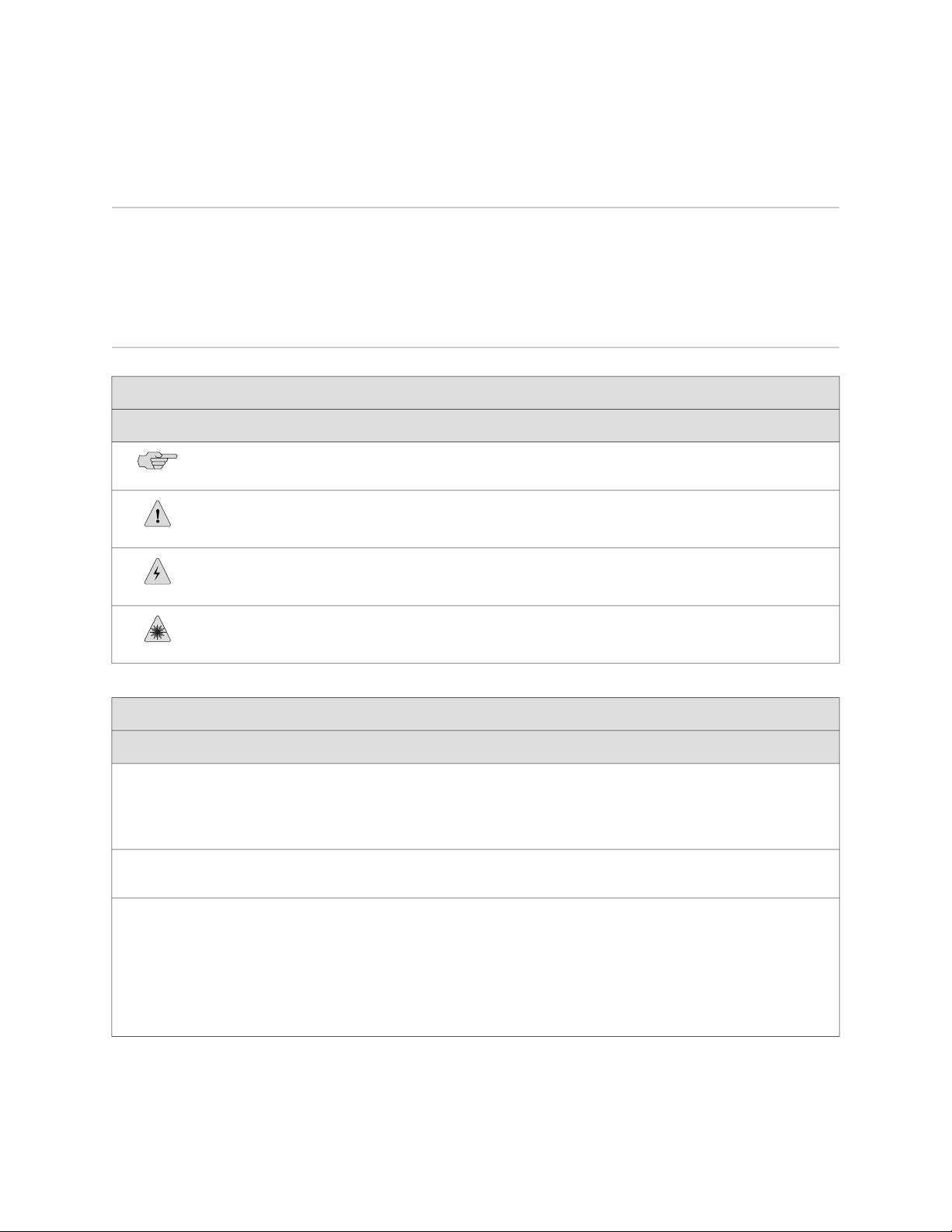
Documentation Symbols Key
Notice Icons
About This Topic Collection
DescriptionMeaningIcon
Indicates important features or instructions.Informational note
Text and Syntax Conventions
Bold text like this
Fixed-width text like this
Italic text like this
Indicates a situation that might result in loss of data or hardware damage.Caution
Alerts you to the risk of personal injury or death.Warning
Alerts you to the risk of personal injury from a laser.Laser warning
Represents text that you type.
Represents output that appears on the
terminal screen.
Introduces important new terms.
■
Identifies book names.
■
Identifies RFC and Internet draft
■
titles.
ExamplesDescriptionConvention
To enter configuration mode, type the
configure command:
user@host> configure
user@host> show chassis alarms
No alarms currently active
A policy term is a named structure
■
that defines match conditions and
actions.
JUNOS System Basics Configuration
■
Guide
RFC 1997, BGP Communities
■
Attribute
Downloading Software ■ xxiii
Page 24

Complete Hardware Guide for EX3200 and EX4200 Ethernet Switches
Text and Syntax Conventions
ExamplesDescriptionConvention
Italic text like this
Plain text like this
| (pipe symbol)
# (pound sign)
[ ] (square brackets)
Indention and braces ( { } )
Represents variables (options for which
you substitute a value) in commands or
configuration statements.
Represents names of configuration
statements, commands, files, and
directories; IP addresses; configuration
hierarchy levels; or labels on routing
platform components.
Enclose optional keywords or variables.< > (angle brackets)
Indicates a choice between the mutually
exclusive keywords or variables on either
side of the symbol. The set of choices is
often enclosed in parentheses for clarity.
Indicates a comment specified on the
same line as the configuration statement
to which it applies.
Enclose a variable for which you can
substitute one or more values.
Identify a level in the configuration
hierarchy.
Configure the machine’s domain name:
[edit]
root@# set system domain-name
domain-name
To configure a stub area, include
■
the stub statement at the [edit
protocols ospf area area-id] hierarchy
level.
The console port is labeled
■
CONSOLE.
stub <default-metric metric>;
broadcast | multicast
(string1 | string2 | string3)
rsvp { # Required for dynamic MPLS only
community name members [ community-ids
]
[edit]
routing-options {
static {
route default {
nexthop address;
retain;
}
}
}
; (semicolon)
J-Web GUI Conventions
Bold text like this
> (bold right angle bracket)
xxiv ■ Documentation Symbols Key
Identifies a leaf statement at a
configuration hierarchy level.
Represents J-Web graphical user
interface (GUI) items you click or select.
Separates levels in a hierarchy of J-Web
selections.
In the Logical Interfaces box, select
■
All Interfaces.
To cancel the configuration, click
■
Cancel.
In the configuration editor hierarchy,
select Protocols>Ospf.
Page 25

Documentation Feedback
We encourage you to provide feedback, comments, and suggestions so that we can
improve the documentation. Send e-mail to techpubs-comments@juniper.net with the
following:
■ Document URL or title
■ Page number if applicable
■ Software version
■ Your name and company
Requesting Technical Support
Technical product support is available through the Juniper Networks Technical
Assistance Center (JTAC). If you are a customer with an active J-Care or JNASC support
contract, or are covered under warranty, and need post-sales technical support, you
can access our tools and resources online or open a case with JTAC.
About This Topic Collection
■ JTAC policies—For a complete understanding of our JTAC procedures and policies,
review the JTAC User Guide located at
http://www.juniper.net/customers/support/downloads/7100059-EN.pdf .
■ Product warranties—For product warranty information, visit
http://www.juniper.net/support/warranty/ .
■ JTAC hours of operation—The JTAC centers have resources available 24 hours a
day, 7 days a week, 365 days a year.
Self-Help Online Tools and Resources
For quick and easy problem resolution, Juniper Networks has designed an online
self-service portal called the Customer Support Center (CSC) that provides you with
the following features:
■
Find CSC offerings: http://www.juniper.net/customers/support/
■
Search for known bugs: http://www2.juniper.net/kb/
■
Find product documentation: http://www.juniper.net/techpubs/
■ Find solutions and answer questions using our Knowledge Base:
http://kb.juniper.net/
■ Download the latest versions of software and review release notes:
http://www.juniper.net/customers/csc/software/
■ Search technical bulletins for relevant hardware and software notifications:
https://www.juniper.net/alerts/
■ Join and participate in the Juniper Networks Community Forum:
http://www.juniper.net/company/communities/
■
Open a case online in the CSC Case Management tool: http://www.juniper.net/cm/
Documentation Feedback ■ xxv
Page 26

Complete Hardware Guide for EX3200 and EX4200 Ethernet Switches
To verify service entitlement by product serial number, use our Serial Number
Entitlement (SNE) Tool: https://tools.juniper.net/SerialNumberEntitlementSearch/
Opening a Case with JTAC
You can open a case with JTAC on the Web or by telephone.
■
Use the Case Management tool in the CSC at http://www.juniper.net/cm/ .
■ Call 1-888-314-JTAC (1-888-314-5822 toll-free in the USA, Canada, and Mexico).
For international or direct-dial options in countries without toll-free numbers, see
http://www.juniper.net/support/requesting support.html .
xxvi ■ Requesting Technical Support
Page 27

Part 1
Switch and Components Overview and
Specifications
■ EX3200 and EX4200 Switches Overview on page 3
■ Component Descriptions on page 13
■ Component Specifications on page 39
Switch and Components Overview and Specifications ■ 1
Page 28

Complete Hardware Guide for EX3200 and EX4200 Ethernet Switches
2 ■ Switch and Components Overview and Specifications
Page 29

Chapter 1
EX3200 and EX4200 Switches Overview
■ EX3200 and EX4200 Switches Hardware Overview on page 3
■ EX3200 Switch Models on page 6
■ EX4200 Switch Models on page 6
■ Chassis Physical Specifications for EX3200 and EX4200 Switches on page 7
■ Front Panel of an EX3200 Switch on page 8
■ Rear Panel of an EX3200 Switch on page 9
■ Front Panel of an EX4200 Switch on page 10
■ Rear Panel of an EX4200 Switch on page 11
EX3200 and EX4200 Switches Hardware Overview
Juniper Networks EX Series Ethernet Switches provide scalable connectivity for the
enterprise market, including branch offices, campus locations, and data centers. The
switches run under the Juniper Networks JUNOS Software, which provides Layer 2
and Layer 3 switching, routing, and security services. The same JUNOS code base
that runs on EX Series switches also runs on all Juniper Networks J Series, M Series,
MX Series, and T Series routers.
■ EX3200 and EX4200 Switch Types on page 3
■ EX3200 Switches on page 4
■ EX4200 Switches on page 4
■ Uplink Modules on page 5
■ Power over Ethernet (PoE) Ports on page 5
EX3200 and EX4200 Switch Types
Juniper Networks EX3200 and EX4200 Ethernet Switches are two closely related
product lines:
■ EX3200 switches—Typically, you deploy these switches in branch environments
or wiring closets.
■ EX4200 switches—You can interconnect EX4200 switches to form a Virtual
Chassis that operates as a single network entity. You can deploy these switches
wherever you need a high density of Gigabit Ethernet ports (24 to 480 ports),
redundancy, or the ability to span a single switch across several wiring closets.
EX3200 and EX4200 Switches Hardware Overview ■ 3
Page 30

Complete Hardware Guide for EX3200 and EX4200 Ethernet Switches
Typically, EX4200 switches are used in large branch offices, campus wiring
closets, and top-of-rack locations in a data center.
Both lines have these features:
■ Run under JUNOS Software for EX Series switches
■ Have options of 24-port and 48-port models
■ Have options of full (all ports) or partial (8 ports) Power over Ethernet (PoE)
capability
■ Have optional uplink modules that provide connection to distribution switches
EX3200 Switches
EX3200 switches provide connectivity for low-density environments. Typically, you
deploy these switches in branch environments or wiring closets where only one
switch is required.
EX4200 Switches
EX3200 switches are available in models with either 24 or 48 ports and with either
all ports equipped for Power over Ethernet (PoE) or only 8 ports equipped for PoE.
All models provide ports that have 10/100/1000Base-T Gigabit Ethernet connectors
and optional 1-gigabit small form-factor pluggable (SFP) transceivers, 10-gigabit small
form-factor pluggable (SFP+) transceivers, or 10-gigabit small form-factor pluggable
(XFP) transceivers for use with fiber connections.
EX3200 switches include:
■ A field-replaceable power supply and an optional additional connection to an
external power source.
■ A field-replaceable fan tray with single fan.
■ JUNOS Software with its modular design that enables failed system processes to
gracefully restart.
EX4200 switches provide connectivity for medium- and high-density environments
and scalability for growing networks. These switches can be deployed wherever you
need a high density of Gigabit Ethernet ports (24 to 480 ports) or redundancy.
Typically, EX4200 switches are used in large branch offices, campus wiring closets,
and data centers where they can be positioned as the top device in a rack to provide
connectivity for all the devices in the rack.
You can connect individual EX4200 switches together to form one unit and manage
the unit as a single chassis, called a Virtual Chassis. You can add more member
switches to the Virtual Chassis as needed, up to a total of 10 members.
EX4200 switches are available in models with 24 or 48 ports and with either all ports
equipped for Power over Ethernet (PoE) or only 8 ports equipped for PoE. All models
provide ports that have 10/100/1000Base-T Gigabit Ethernet connectors and optional
1-gigabit small form-factor pluggable (SFP) transceivers, 10-gigabit small form-factor
4 ■ EX3200 and EX4200 Switches Hardware Overview
Page 31

Chapter 1: EX3200 and EX4200 Switches Overview
pluggable (SFP+) transceivers, or 10-gigabit small form-factor pluggable (XFP)
transceivers for use with fiber connections.
Additionally, a 24-port model provides 100Base-FX/1000Base-X SFP ports. This model
is typically used as a small distribution switch.
All EX4200 switches have dedicated 64-Gbps Virtual Chassis ports that allow you to
connect the switches to each other. You can also use optional uplink module ports
to connect members of a Virtual Chassis across multiple wiring closets.
To provide carrier-class reliability, EX4200 switches include:
■ Dual redundant power supplies that are field-replaceable and hot-swappable. An
optional additional connection to an external power source is also available.
■ A field-replaceable fan tray with three fans. The switch remains operational if a
single fan fails.
■ Redundant Routing Engines in a Virtual Chassis configuration. This redundancy
enables GRES (graceful Routing Engine switchover) and nonstop active routing.
■ JUNOS Software with its modular design that enables failed system processes to
gracefully restart.
Uplink Modules
Optional uplink modules are available for all EX3200 and EX4200 switches. Uplink
modules provide two 10-gigabit small form-factor pluggable (XFP) transceivers, four
1-gigabit small form-factor pluggable (SFP) transceivers, or two 10-gigabit small
form-factor pluggable (SFP+) transceivers. You can use XFP, SFP, or SFP+ ports to
connect an access switch to a distribution switch or to interconnect member switches
of a Virtual Chassis across multiple wiring closets.
Power over Ethernet (PoE) Ports
PoE ports provide electrical current to devices through the network cables so that
separate power cords for devices such as IP phones, wireless access points, and
security cameras are unnecessary. Both the EX3200 and EX4200 switches have
options of full (all 24 or 48 ports) or partial (8 ports) PoE capability.
Full PoE models are primarily used in IP telephony environments. Partial PoE models
are used in environments where, for example, only a few ports for wireless access
points or security cameras are required.
Related Topics ■ EX3200 Switch Models on page 6
■ EX4200 Switch Models on page 6
■ Field-Replaceable Units in EX3200 and EX4200 Switches on page 16
■ Site Preparation Checklist for EX3200 and EX4200 Switches on page 81
EX3200 and EX4200 Switches Hardware Overview ■ 5
Page 32

Complete Hardware Guide for EX3200 and EX4200 Ethernet Switches
EX3200 Switch Models
The EX3200 switch is available with 24 or 48 ports with partial or full Power over
Ethernet (PoE) capability. Table 1 on page 6 lists the EX3200 switch models.
Table 1: EX3200 Switch Models
EX3200-24T
switch
EX3200-48T
switch
Related Topics ■ EX4200 Switch Models on page 6
■ Front Panel of an EX3200 Switch on page 8
■ Rear Panel of an EX3200 Switch on page 9
■ EX3200 and EX4200 Switches Hardware Overview on page 3
EX4200 Switch Models
The EX4200 switch is available with 24 or 48 ports and with partial or full Power
over Ethernet (PoE) capability. Table 2 on page 6 lists the EX4200 switch models.
Number of PoE-enabled
PortsAccess PortsTypical DeploymentModel
Power Supply
(Minimum)
320 WFirst 8 ports24 Gigabit EthernetAccess or Distribution
600 WAll 24 ports24 Gigabit EthernetAccess switchEX3200-24P
320 WFirst 8 ports48 Gigabit EthernetAccess or Distribution
930 WAll 48 ports48 Gigabit EthernetAccess switchEX3200-48P
Table 2: EX4200 Switch Models
EX4200-24F
(SFP) transceivers
6 ■ EX3200 Switch Models
Power Supply
(Minimum)Number of PoE-enabled PortsPortsModel
320 WFirst 8 ports24 Gigabit EthernetEX4200-24T
600 WAll 24 ports24 Gigabit EthernetEX4200-24P
320 WFirst 8 ports48 Gigabit EthernetEX4200-48T
930 WAll 48 ports48 Gigabit EthernetEX4200-48P
320 WNot applicable24 small form-factor pluggable
Page 33

Chapter 1: EX3200 and EX4200 Switches Overview
Related Topics ■ EX3200 Switch Models on page 6
■ Front Panel of an EX4200 Switch on page 10
■ Rear Panel of an EX4200 Switch on page 11
■ EX3200 and EX4200 Switches Hardware Overview on page 3
Chassis Physical Specifications for EX3200 and EX4200 Switches
The EX3200 and EX4200 switch chassis is a rigid sheet-metal structure that houses
the hardware components. Table 3 on page 7 summarizes the physical specifications
of the EX3200 and EX4200 switch chassis.
Table 3: Physical Specifications of the EX3200 and EX4200 Switch Chassis
ValueDescription
1.75 in. (4.45 cm)Chassis height
Chassis width
Chassis depth
Weight
17.25 in. (43.82 cm)
■
19 in. (48.2 cm) with mounting brackets attached
■
Without power supply installed—17 in. (43.18 cm)
■
With power supply installed:
■
320 W AC power supply or 190 W DC power supply installed—17 in. (43.18 cm)
■
600 W or 930 W AC power supply installed—19.25 in. (48.9 cm)
■
EX3200 switch with 1 power supply: 15–17 lb (6.8–7.7 kg)
■
EX4200 switch with 1 power supply: 16–18 lb (7.2–8.2 kg)
■
320 W AC power supply: 2.5 lb (1.1 kg)
■
600 W and 930 W AC power supplies: 3.1 lb (1.4 kg)
■
190 W DC power supply: 2.5 lb (1.1 kg)
■
Related Topics ■ Rack Requirements for EX3200 and EX4200 Switches on page 87
■ Cabinet Requirements for EX3200 and EX4200 Switches on page 89
■ Mounting an EX3200 or EX4200 Switch on page 116
■ Installing and Connecting an EX3200 or EX4200 Switch on page 113
■ Installing and Removing EX3200 and EX4200 Switch Hardware Components on
page 129
Chassis Physical Specifications for EX3200 and EX4200 Switches ■ 7
Page 34

Complete Hardware Guide for EX3200 and EX4200 Ethernet Switches
Front Panel of an EX3200 Switch
The front panel of an EX3200 switch consists of the following components:
■ 10/100/1000Base-T Gigabit Ethernet ports, some or all of which are enabled for
Power over Ethernet (PoE)
■ Uplink module ports—SFP, SFP+, or XFP ports (The uplink module is an optional
feature.)
■ LCD panel and the LCD navigation buttons
■ Chassis status LEDs
■ Network port LEDs
Figure 1 on page 8 shows the front panel of an EX3200 switch with 48 Gigabit
Ethernet ports. Figure 2 on page 8 shows the front panel of an EX3200 switch with
24 Gigabit Ethernet ports. Models are available that have either all ports equipped
for Power over Ethernet (PoE) or only 8 ports equipped for PoE. All ports have
10/100/1000Base-T Gigabit Ethernet connectors.
Figure 1: EX3200 Switch with 48 Gigabit Ethernet Ports
Figure 2: EX3200 Switch with 24 Gigabit Ethernet Ports
Related Topics ■ Chassis Status LEDs in EX3200 Switches on page 17
■ Rear Panel of an EX3200 Switch on page 9
■ Network Port LEDs in EX3200 and EX4200 Switches on page 20
■ Network Port Connector Pinout Information for an EX3200 or EX4200 Switch
on page 40
■ LCD Panel in EX3200 and EX4200 Switches on page 13
■ Installing and Removing EX3200 and EX4200 Switch Hardware Components on
page 129
8 ■ Front Panel of an EX3200 Switch
Page 35

■ Installing an Uplink Module in an EX3200 or EX4200 Switch on page 133
■ Removing an Uplink Module from an EX3200 or EX4200 Switch on page 175
Rear Panel of an EX3200 Switch
The rear panel of the EX3200 switch consists of the following components:
■ Protective earthing terminal
■ Temperature shutdown LED
■ Management Ethernet port
■ Console port
■ USB port
■ ESD point
Chapter 1: EX3200 and EX4200 Switches Overview
■ Fan tray
■ Power supply
Figure 3 on page 9 shows the rear panel of an EX3200 switch with a 320 W power
supply. All EX3200 switches have the same rear panel. The 320 W AC power supply
and the 190 W DC power supply are flush with the chassis. The 600 W AC power
supply and 930 W AC power supply extend out of the chassis by 2.25 in. The power
cord retainer clips extend out of the power supply by 3 in.
Figure 3: EX3200 Switch Rear Panel
Related Topics ■ Field-Replaceable Units in EX3200 and EX4200 Switches on page 16
■ Front Panel of an EX3200 Switch on page 8
■ USB Port Specifications for an EX Series Switch on page 39
■ Cooling System and Airflow in an EX3200 Switch on page 31
■ Power Supply in EX3200 and EX4200 Switches on page 26
■ Prevention of Electrostatic Discharge Damage on EX Series Switches on page 236
Rear Panel of an EX3200 Switch ■ 9
Page 36

Complete Hardware Guide for EX3200 and EX4200 Ethernet Switches
■ Connecting Earth Ground to an EX Series Switch on page 141
■ Installing and Removing EX3200 and EX4200 Switch Hardware Components on
page 129
Front Panel of an EX4200 Switch
The front panel of an EX4200 switch consists of the following components:
■ Network ports—depending on the switch model, either of:
■ 10/100/1000Base-T Gigabit Ethernet ports, some or all of which are enabled
for Power over Ethernet (PoE)
■ 100Base-FX/1000Base-X SFP ports for use with fiber-optic connections
■ Uplink module ports—SFP, SFP+, or XFP ports (The uplink module is an optional
feature.)
■ LCD panel and the LCD navigation buttons
■ Chassis status LEDs
■ Network port LEDs
Figure 4 on page 10 shows the front panel of an EX4200 switch with 48 Gigabit
Ethernet ports. Figure 5 on page 10 shows the front panel of an EX4200 switch with
24 Gigabit Ethernet ports. Figure 6 on page 11 shows the front panel of an
EX4200-24F switch with 24 SFP ports for use with fiber-optic connectors.
Figure 4: EX4200 Switch with 48 Gigabit Ethernet Ports
Figure 5: EX4200 Switch with 24 Gigabit Ethernet Ports
10 ■ Front Panel of an EX4200 Switch
Page 37

Chapter 1: EX3200 and EX4200 Switches Overview
Figure 6: EX4200-24F Switch with 24 SFP Ports
Related Topics ■ Chassis Status LEDs in EX4200 Switches on page 18
■ Rear Panel of an EX4200 Switch on page 11
■ Network Port LEDs in EX3200 and EX4200 Switches on page 20
■ Network Port Connector Pinout Information for an EX3200 or EX4200 Switch
on page 40
■ LCD Panel in EX3200 and EX4200 Switches on page 13
■ Optical Interface Support in EX3200 and EX4200 Switches on page 43
■ Installing and Removing EX3200 and EX4200 Switch Hardware Components on
page 129
■ Installing an Uplink Module in an EX3200 or EX4200 Switch on page 133
■ Removing an Uplink Module from an EX3200 or EX4200 Switch on page 175
Rear Panel of an EX4200 Switch
The rear panel of the EX4200 switch consists of the following components:
■ Fan tray
■ Virtual Chassis ports (VCPs)
■ USB port
■ Temperature shutdown LED
■ Management Ethernet port
■ Console port
■ ESD point
■ Power supply or power supplies
Figure 7 on page 12 shows the rear panel of an EX4200 switch. All EX4200 switches
have the same rear panel. The 320 W AC power supply and the 190 W DC are flush
with the chassis. The 600 W AC power supply and 930 W AC power supply extend
out of the chassis by 2.25 in. Power cord retainer clips extend out of the power supply
by 3 in.
Rear Panel of an EX4200 Switch ■ 11
Page 38

g020084
Virtual
chassis
ports
USB
port
Management
Ethernet
port
Fan
tray
Console
port
Power
Supply 1
Power
Supply 0
Protective earthing
terminal (on side panel)
ESD
point
Temperature
shutdown LED
Complete Hardware Guide for EX3200 and EX4200 Ethernet Switches
Figure 7: EX4200 Switch Rear Panel
Related Topics ■ Field-Replaceable Units in EX3200 and EX4200 Switches on page 16
■ Front Panel of an EX4200 Switch on page 10
■ USB Port Specifications for an EX Series Switch on page 39
■ Cooling System and Airflow in an EX4200 Switch on page 32
■ Power Supply in EX3200 and EX4200 Switches on page 26
■ Prevention of Electrostatic Discharge Damage on EX Series Switches on page 236
■ Connecting Earth Ground to an EX Series Switch on page 141
■ Installing and Removing EX3200 and EX4200 Switch Hardware Components on
page 129
■ Understanding Virtual Chassis Hardware Configuration on an EX4200 Switch on
page 101
12 ■ Rear Panel of an EX4200 Switch
Page 39

Chapter 2
Component Descriptions
■ LCD Panel in EX3200 and EX4200 Switches on page 13
■ Field-Replaceable Units in EX3200 and EX4200 Switches on page 16
■ Chassis Status LEDs in EX3200 Switches on page 17
■ Chassis Status LEDs in EX4200 Switches on page 18
■ Network Port LEDs in EX3200 and EX4200 Switches on page 20
■ Management Port LEDs in EX3200 and EX4200 Switches on page 24
■ Power Supply in EX3200 and EX4200 Switches on page 26
■ AC Power Supply LEDs in EX3200 and EX4200 Switches on page 29
■ DC Power Supply LEDs in EX3200 and EX4200 Switches on page 30
■ Cooling System and Airflow in an EX3200 Switch on page 31
■ Cooling System and Airflow in an EX4200 Switch on page 32
■ Uplink Modules in EX3200 and EX4200 Switches on page 33
LCD Panel in EX3200 and EX4200 Switches
The LCD panel on the front panel of EX3200 and EX4200 switches shows two lines
of text, each a maximum of 16 characters in length. The LCD panel displays a variety
of information about the switch and also provides a menu to perform basic operations
such as initial setup and reboot.
There are two navigation buttons—Menu and Enter—to the right of the LCD panel.
See Figure 8 on page 13.
Figure 8: LCD Panel in EX3200 and EX4200 Switches
You can configure the second line of the LCD panel to display a custom message. If
the LCD panel is configured to display a custom message, the Menu button and the
LCD Panel in EX3200 and EX4200 Switches ■ 13
Page 40

Complete Hardware Guide for EX3200 and EX4200 Ethernet Switches
Enter button are disabled. See “Configuring the LCD Panel Display on EX Series
Switches (CLI Procedure)” on page 166.
The LCD panel has a backlight. If the LCD panel is idle for 60 seconds, the backlight
turns off. You can turn on the backlight by pressing the Menu or Enter button once.
After turning on the backlight, you can toggle between the LCD panel menus by
pressing the Menu button and navigate through the menu options by pressing the
Enter button.
NOTE: The chassis viewer in the J-Web interface also displays the LCD panel. From
the J-Web interface, you can view real-time status information in the LCD panel. See
Dashboard for EX Series Switches.
This topic describes:
■ LCD Panel Modes on page 14
■ LCD Panel Menus on page 15
LCD Panel Modes
The LCD panel operates in four modes: boot, idle, status, and maintenance.
The LCD panel operates in boot mode during switch reboot. The boot mode displays
the key milestones in the switch boot process. The boot mode does not have any
menu options. After the boot process is complete, the LCD panel automatically reverts
to the Idle menu.
In an EX3200 switch, the first line of the LCD panel displays the hostname.
In an EX4200 switch that is not a member of a Virtual Chassis, the first line of the
LCD panel displays the slot number, the role of the switch, and hostname. For a
standalone EX4200 switch, the slot number is always 00 and the role is always RE
(for master).
In an EX4200 switch that is a member of a Virtual Chassis, the first line of the LCD
panel displays:
■ The slot number (the member ID for the Virtual Chassis member)
■
Role of the switch in a Virtual Chassis (RE for master, BK for backup, and LC for
linecard member)
■ Hostname
In the idle mode, the second line displays the mode of the network ports’ Status LED
and the number of chassis alarms. The number of alarms is updated every second.
In the status mode, the second line displays:
■ Virtual Chassis port (VCP) status (for an EX4200 switch that is a member of a
Virtual Chassis)
■ Status of the power supply
14 ■ LCD Panel in EX3200 and EX4200 Switches
Page 41

LCD Panel Menus
Chapter 2: Component Descriptions
■ Status of the fan and temperature
■ Version of JUNOS Software for EX Series switches loaded on the switch
In the maintenance mode, the second line displays one of the following options that
you can use to configure and troubleshoot the switch:
■ System halt
■ System reboot
■ Load rescue
■ Request VC port
■ Factory default
■ System EZSetup
The LCD panel has three menus: Idle, Status, and Maintenance. You can toggle
between the LCD panel menus by pressing the Menu button and navigate through
the menu options by pressing the Enter button.
Table 4 on page 15 describes the LCD panel menu options.
Table 4: LCD Panel Menu Options in EX3200 and EX4200 Switches
DescriptionMenu
IDLE
STATUS
In the Idle menu:
■
Press Enter to cycle through the Status LED modes:
ADM (administrative status)
■
DPX (duplex)
■
Power over Ethernet (PoE)
■
SPD (speed)
■
See “Network Port LEDs in EX3200 and EX4200 Switches” on page 20 for information on the Status
LED modes.
EXIT IDLE MENU?—Select this option to exit the Idle menu.
■
The Status menu has the following options:
Show VCP Status—Displays the Virtual Chassis port (VCP) status: Up, Down, Disabled. This menu option
■
is available only for an EX4200 switch that is a member of a Virtual Chassis configuration.
Show PSU Status—Displays the status of the power supply: OK, Failed, Absent.
■
Show Environment Status—Displays the status of the fan and temperature:
■
Fan status: OK, Failed, Absent
■
Temp status: OK, High, Shutdown
■
Show JUNOS Version Status—Displays the version of JUNOS Software for EX Series switches loaded on
■
the switch.
EXIT STAT MENU?—Select this option to exit the Status menu.
■
LCD Panel in EX3200 and EX4200 Switches ■ 15
Page 42

Complete Hardware Guide for EX3200 and EX4200 Ethernet Switches
Table 4: LCD Panel Menu Options in EX3200 and EX4200 Switches (continued)
DescriptionMenu
MAINT
(Maintenance
Menu)
The Maintenance menu has the following options to configure and troubleshoot the switch:
■
SYSTEM HALT?—Select this option using the Enter button to halt the switch. Press the Enter button again
to confirm the halt. Press the Menu button to go to the next option in the Maintenance menu.
■
SYSTEM REBOOT?—Select this option using the Enter button to reboot the switch. Press the Enter button
again to confirm the reboot. Press the Menu button to go to the next option in the Maintenance menu.
■
LOAD RESCUE?—Select this option using the Enter button to roll back the switch to the rescue
configuration. Press the Enter button again to confirm the rollback. Press the Menu button to go to the
next option in the Maintenance menu.
■
REQUEST VC PORT?—Select this option using the Enter button to configure an uplink module port or an
EX4200-24F network port to be a Virtual Chassis port (VCP) or to delete a VCP from the switch
configuration (when you delete the VCP, the port is reset to an uplink module port or an EX4200-24F
network port).
For information on how to use the REQUEST VC PORT option, see Setting an Uplink Module Port or an
EX4200-24F Network Port as a Virtual Chassis Port Using the LCD Panel.
■
FACTORY DEFAULT?—Select this option using the Enter button to restore the switch to the factory default
configuration. Press the Enter button again to confirm the restoration. Press the Menu button to go to
the next option in the Maintenance menu.
■
ENTER EZSETUP?—Select this option using the Enter button to launch EZSetup. Press the Enter button
again to confirm the launch. Press the Menu button to go to the next option in the Maintenance menu.
You can use the ENTER EZSETUP option only if the switch is in the factory default configuration.
For information about EZSetup, see “Connecting and Configuring an EX Series Switch (J-Web Procedure)”
on page 163.
EXIT MAINT MENU?—Select this option to exit the Maintenance menu.
■
You can disable the Maintenance menu in the LCD panel. See “Configuring the LCD Panel Display on EX
Series Switches (CLI Procedure)” on page 166.
Related Topics ■ Front Panel of an EX3200 Switch on page 8
■ Front Panel of an EX4200 Switch on page 10
■ Field-Replaceable Units in EX3200 and EX4200 Switches on page 16
■ Connecting and Configuring an EX Series Switch (CLI Procedure) on page 161
■ Connecting and Configuring an EX Series Switch (J-Web Procedure) on page 163
Field-Replaceable Units in EX3200 and EX4200 Switches
Field-replaceable units (FRUs) are components that you can replace at your site. The
field-replaceable units (FRUs) in EX3200 and EX4200 switches are:
■ Power supply
■ Fan tray
■ Uplink module
■ SFP transceiver
16 ■ Field-Replaceable Units in EX3200 and EX4200 Switches
Page 43

Chapter 2: Component Descriptions
■ SFP+ transceiver
■ XFP transceiver
NOTE: Uplink modules are not part of the standard package and must be ordered
separately.
The power supply, fan tray, uplink module, and transceivers are hot-removable and
hot-insertable: You can remove and replace them without powering off the switch
or disrupting switch functions.
NOTE: If you have a Juniper J-Care service contract, register any addition, change,
or upgrade of hardware components at
https://www.juniper.net/customers/csc/management/updateinstallbase.jsp. Failure to do so
can result in significant delays if you need replacement parts. This note applies if
you change the type of power supply or add a new type of uplink module. It does
not apply if you replace these components with the same type of component.
Related Topics ■ Uplink Modules in EX3200 and EX4200 Switches on page 33
■ Installing a Power Supply in an EX3200 or EX4200 Switch on page 130
■ Removing a Power Supply from an EX3200 or EX4200 Switch on page 172
■ Installing a Fan Tray in an EX3200 or EX4200 Switch on page 132
■ Removing a Fan Tray from an EX3200 or EX4200 Switch on page 174
■ Installing an Uplink Module in an EX3200 or EX4200 Switch on page 133
■ Removing an Uplink Module from an EX3200 or EX4200 Switch on page 175
■ Installing a Transceiver in an EX Series Switch on page 136
■ Removing a Transceiver from an EX Series Switch on page 177
Chassis Status LEDs in EX3200 Switches
The front panel of an EX3200 switch has three LEDs on the far right side of the panel,
next to the LCD panel (see Figure 9 on page 17).
Figure 9: Chassis Status LEDs in an EX3200 Switch
Chassis Status LEDs in EX3200 Switches ■ 17
Page 44

Complete Hardware Guide for EX3200 and EX4200 Ethernet Switches
Table 5 on page 18 describes the chassis status LEDs in an EX3200 switch, their
colors and states, and the status they indicate. You can view the colors of the three
LEDs remotely through the CLI by issuing the operational mode command show
chassis lcd.
Table 5: Chassis Status LEDs in an EX3200 Switch
State and DescriptionColorLED Label
There is no alarm.UnlitALM (Alarm)
There is a major alarm.Red
There is a minor alarm.Amber
Related Topics Front Panel of an EX3200 Switch on page 8■
GreenSYS (System)
GreenMST (Master)
On steadily—JUNOS Software for EX Series switches has
■
been loaded on the switch.
Blinking—The switch is booting.
■
This LED is always on and is meaningful only on EX4200
switches.
A major alarm (red) indicates a critical error condition that requires immediate action.
A minor alarm (amber) indicates a noncritical condition that requires monitoring or
maintenance. A minor alarm that is left unchecked might cause interruption in service
or performance degradation.
NOTE: The amber glow of the Alarm LED that indicates a minor alarm closely
resembles the red glow that indicates a major alarm.
All three LEDs can be lit simultaneously.
■ Checking Active Alarms with the J-Web Interface
■ Understanding Alarm Types and Severity Levels on EX Series Switches
Chassis Status LEDs in EX4200 Switches
The front panel of an EX4200 switch has three LEDs on the far right side of the panel,
next to the LCD panel (see Figure 10 on page 19).
18 ■ Chassis Status LEDs in EX4200 Switches
Page 45

Figure 10: Chassis Status LEDs in an EX4200 Switch
Table 6 on page 19 describes the chassis status LEDs in an EX4200 switch, their
colors and states, and the status they indicate. You can view the colors of the three
LEDs remotely through the CLI by issuing the operational mode command show
chassis lcd.
Table 6: Chassis Status LEDs in an EX4200 Switch
Chapter 2: Component Descriptions
State and DescriptionColorLED Label
There is no alarm.UnlitALM (Alarm)
There is a major alarm.Red
There is a minor alarm.Amber
GreenSYS (System)
GreenMST (Master)
On steadily—JUNOS Software for EX Series switches has
■
been loaded on the switch.
Blinking—The switch is booting.
■
On steadily—The switch is the master in the Virtual
■
Chassis configuration.
Blinking—The switch is the backup in the Virtual Chassis
■
configuration.
Off—The switch is a linecard member in the Virtual
■
Chassis configuration.
A major alarm (red) indicates a critical error condition that requires immediate action.
A minor alarm (amber) indicates a noncritical condition that requires monitoring or
maintenance. A minor alarm that is left unchecked might cause interruption in service
or performance degradation.
NOTE: The amber glow of the Alarm LED that indicates a minor alarm closely
resembles the red glow that indicates a major alarm.
Related Topics Front Panel of an EX4200 Switch on page 10■
All three LEDs can be lit simultaneously.
■ Checking Active Alarms with the J-Web Interface
Chassis Status LEDs in EX4200 Switches ■ 19
Page 46

Complete Hardware Guide for EX3200 and EX4200 Ethernet Switches
■ Understanding Alarm Types and Severity Levels on EX Series Switches
Network Port LEDs in EX3200 and EX4200 Switches
Each network port on an EX3200 or EX4200 switch has two LEDs. The four figures
in this topic show the location of those LEDs:
■ Figure 11 on page 20 shows the location of the LEDs on the network ports on
the front panel.
■ Figure 12 on page 20 shows the location of the LEDs on the uplink module ports
on the SFP uplink module.
■ Figure 13 on page 21 shows the location of the LEDs on the uplink module ports
on the SFP+ uplink module.
■ Figure 14 on page 21 shows the location of the LEDs on the uplink module ports
on the XFP uplink module.
Figure 11: LEDs on the Network Ports on the Front Panel
Figure 12: LEDs on the Uplink Module Ports on the SFP Uplink Module
20 ■ Network Port LEDs in EX3200 and EX4200 Switches
Page 47

g020108
Link/Activity
LED
Link/Activity
LED
Status LED Status LED
Port 0 Port 1
Chapter 2: Component Descriptions
Figure 13: LEDs on the Uplink Module Ports on the SFP+ Uplink Module
Figure 14: LEDs on the Uplink Module Ports on the XFP Uplink Module
The LEDs labeled Link/Activity LED in Figure 11 on page 20, Figure 12 on page 20,
Figure 14 on page 21, and Figure 13 on page 21 indicate link activity. The LEDs
labeled Status LED in Figure 11 on page 20, Figure 12 on page 20, Figure 14 on
page 21, and Figure 13 on page 21 indicate the status of one of the four port
parameters. The port parameters are administrative status, duplex mode, Power
over Ethernet (PoE) status, and speed.
Table 7 on page 22 describes the Link/Activity LED.
Network Port LEDs in EX3200 and EX4200 Switches ■ 21
Page 48

Complete Hardware Guide for EX3200 and EX4200 Ethernet Switches
Table 7: Link/Activity LED on Network Ports in EX3200 and EX4200 Switches
State and DescriptionColorLED
GreenLink/Activity
Blinking—The port and the link are active, and there is
■
link activity.
On steadily—The port and the link are active, but there
■
is no link activity.
Off—The port is not active.
■
Table 8 on page 23 describes the Status LED. From the Idle menu of the LCD, use
the Enter button on the LCD panel to toggle between the ADM, DPX, POE, and SPD
indicators.
22 ■ Network Port LEDs in EX3200 and EX4200 Switches
Page 49

Table 8: Status LED on Network Ports in EX3200 and EX4200 Switches
State and DescriptionLCD IndicatorLED
Chapter 2: Component Descriptions
LED: ADMStatus
LED: DPX
LED: POE
Indicates the administrative status (enabled or disabled). The
status indicators are:
Green—Administrative status enabled.
■
Unlit—Administrative status disabled.
■
Indicates the duplex mode.
The uplink module ports are always set to full-duplex;
therefore, the LED is always green.
The status indicators for network ports on the front panel are:
Green—Port is set to full-duplex mode.
■
Unlit—Port is set to half-duplex mode.
■
Indicates the PoE status.
PoE is not enabled on uplink module ports; therefore, the LED
for those ports is always unlit.
The status indicators for network ports on the front panel are:
Green—PoE is enabled on the port.
■
Amber—PoE is enabled on the port, but no power is
■
drawn from the port because of one of the following:
No device that draws power from the port is
■
connected to the port.
A device that draws power from the port is
■
connected to the port, but the device is not drawing
any power from the port.
Unlit—PoE is not enabled on the port.
■
LED: SPD
Network Port LEDs in EX3200 and EX4200 Switches ■ 23
Page 50

Complete Hardware Guide for EX3200 and EX4200 Ethernet Switches
Table 8: Status LED on Network Ports in EX3200 and EX4200 Switches (continued)
State and DescriptionLCD IndicatorLED
Indicates the speed.
The speed indicators for network ports on the front panel are:
One blink per second—10 Mbps
■
Two blinks per second—100 Mbps
■
Three blinks per second—1000 Mbps
■
The speed indicators for network ports on the SFP uplink
module are:
Green—1000 Mbps
■
Unlit—10/100 Mbps
■
The speed indicators for network ports on the SFP+ uplink
module are:
Green—The speed of the transceiver installed in the port
■
is the same as the speed at which the uplink module port
is configured to operate.
Unlit—The speed of the transceiver installed in the port
■
is not the same as the speed at which the uplink module
port is configured to operate.
The speed of the XFP uplink module ports is always 10 Gbps;
therefore, the LED is always green.
Related Topics ■ Front Panel of an EX3200 Switch on page 8
■ Front Panel of an EX4200 Switch on page 10
■ Uplink Modules in EX3200 and EX4200 Switches on page 33
■ LCD Panel in EX3200 and EX4200 Switches on page 13
Management Port LEDs in EX3200 and EX4200 Switches
The management port on EX3200 and EX4200 switches has two LEDs that indicate
link/activity and port status (see Figure 15 on page 25 or Figure 16 on page 25). The
management port is set to full-duplex and the speed is set to 100 Mbps.
24 ■ Management Port LEDs in EX3200 and EX4200 Switches
Page 51

Chapter 2: Component Descriptions
Figure 15: LEDs on the Management Port on an EX3200 Switch
Figure 16: LEDs on the Management Port on an EX4200 Switch
Table 9 on page 25 describes the Link/Activity LED.
Table 9: Link/Activity LED on the Management Port on an EX3200 or EX4200 Switch
State and DescriptionColorLED
GreenLink/Activity
Blinking—The port and the link are active, and there is
■
link activity.
On steadily—The port and the link are active, but there
■
is no link activity.
Off—The port is not active.
■
Table 10 on page 25 describes the Status LED (administrative status).
Table 10: Status LED on the Management Port on an EX3200 or EX4200 Switch
State and DescriptionColorLED
GreenStatus
On steadily—Administrative status is enabled.
■
Off—Administrative status is disabled.
■
Management Port LEDs in EX3200 and EX4200 Switches ■ 25
Page 52

Complete Hardware Guide for EX3200 and EX4200 Ethernet Switches
Related Topics See Rear Panel of an EX3200 Switch on page 9 for port location.■
■ See Rear Panel of an EX4200 Switch on page 11 for port location.
■ Connecting an EX Series Switch to a Network for Out-of-Band Management on
page 152
Power Supply in EX3200 and EX4200 Switches
The power supply in EX3200 and EX4200 switches (see Figure 17 on page 27, Figure
18 on page 27 and Figure 19 on page 27) is a hot-removable and hot-insertable
field-replaceable unit (FRU) that you can install on the rear panel without powering
off the switch or disrupting the switching function. EX4200 switches have an internal
redundant power supply, making the power supply in EX4200 switches fully
redundant. The power supply in EX3200 switches is not redundant.
EX3200 and EX4200 switches use power that provides two DC output voltages: 12 V
for system and logic power and 48–51 V (or higher, to compensate for voltage drops
along the path from the power supplies to the RJ-45 connector) for PoE ports.
The AC power supply in EX3200 and EX4200 switches is available in 320 W, 600 W,
and 930 W models. The exterior of the 600 W model is identical to that of the 930 W
model. The 320 W power supply is flush with the chassis. The 600 W power supply
and 930 W power supply extend out of the chassis by 2.25 in. The power cord retainer
clips extend out of the power supply by 3 in. The number of ports on which PoE is
enabled determines the minimum power requirements.
The DC power supply in EX3200 and EX4200 switches is available in a 190 W model,
with dual input feeds for power resiliency. You can install redundant DC power
supplies in an EX4200 switch to achieve both power supply and power feed resiliency.
NOTE: The DC power supply in EX3200 and EX4200 switches does not support
Power over Ethernet (PoE); you can use either an external power injector or an AC
power supply to supply power to PoE devices that you connect to the switch.
NOTE: The DC power supply in EX3200 and EX4200 switches has four terminals
labeled A+, B+, A–, and B– (see Figure 19 on page 27) for connecting DC power
source cables labeled positive (+) and negative (–). The DC power supplies for EX3200
and EX4200 switches are shipped with jumpers from A+ input to B+ input tied
together and jumpers from A– input to B– input tied together.
NOTE: The A+ and B+ terminals are referred to as +RTN and A– and B– terminals
are referred to as –48 V in “DC Power Wiring Sequence Warning for EX Series
Switches” on page 245 and “DC Power Electrical Safety Guidelines for EX Series
Switches” on page 241.
26 ■ Power Supply in EX3200 and EX4200 Switches
Page 53

Chapter 2: Component Descriptions
Figure 17: 320 W AC Power Supply in EX3200 and EX4200 Switches
Figure 18: 600 W and 930 W AC Power Supplies in EX3200 and EX4200 Switches
Figure 19: DC Power Supply in EX3200 and EX4200 Switches
Table 11 on page 28 lists the minimum power requirements for each model of
EX3200 switch. The maximum power available to each PoE port is 15.4 W.
Power Supply in EX3200 and EX4200 Switches ■ 27
Page 54

Complete Hardware Guide for EX3200 and EX4200 Ethernet Switches
Table 11: Minimum Power Requirements for an EX3200 Switch
Table 12 on page 28 lists the minimum power requirements for each model of
EX4200 switch. The maximum power available to each PoE port is 15.4 W.
Minimum Power RequirementNumber of PoE-enabled PortsModel Number
320 W8EX3200-24T
320 W8EX3200-48T
600 W24EX3200-24P
930 W48EX3200-48P
190 W0EX3200-24T-DC
190 W0EX3200-48T-DC
Table 12: Minimum Power Requirements for an EX4200 Switch
To avoid electrical injury, follow instructions in “Installing a Power Supply in an
EX3200 or EX4200 Switch” on page 130 and “Removing a Power Supply from an
EX3200 or EX4200 Switch” on page 172 carefully.
Minimum Power RequirementNumber of PoE-enabled PortsModel Number
320 W8EX4200-24T
320 W8EX4200-48T
600 W24EX4200-24P
930 W48EX4200-48P
320 W–EX4200-24F
190 W0EX4200-24T-DC
190 W0EX4200-48T-DC
190 W–EX4200-24F-DC
28 ■ Power Supply in EX3200 and EX4200 Switches
Page 55

Chapter 2: Component Descriptions
NOTE: After powering on an EX3200 or EX4200 switch, wait for at least 60 seconds
before powering it off. After powering off an EX3200 or EX4200 switch, wait for at
least 60 seconds before powering it back on.
After an EX3200 or EX4200 switch has been powered on, it can take up to 60 seconds
for status indicators—such as LEDs on the power supply, show chassis command
output, and messages on the LCD—to indicate that the power supply is functioning
normally. Ignore error indicators that appear during the first 60 seconds.
Related Topics ■ AC Power Cord Specifications for EX3200 and EX4200 Switches on page 98
■ AC Power Supply LEDs in EX3200 and EX4200 Switches on page 29
■ DC Power Supply LEDs in EX3200 and EX4200 Switches on page 30
■ Rear Panel of an EX3200 Switch on page 9
■ Rear Panel of an EX4200 Switch on page 11
■ Field-Replaceable Units in EX3200 and EX4200 Switches on page 16
■ Power Specifications for EX3200 and EX4200 Switches on page 97
■ Prevention of Electrostatic Discharge Damage on EX Series Switches on page 236
■ Connecting AC Power to an EX3200 or EX4200 Switch on page 146
■ Connecting DC Power to an EX3200 or EX4200 Switch on page 148
■ Connecting Earth Ground to an EX Series Switch on page 141
AC Power Supply LEDs in EX3200 and EX4200 Switches
The AC power supply in an EX3200 or EX4200 switch is on the rear panel. Table 13
on page 29 describes the LEDs on the AC power supplies in EX3200 and EX4200
switches.
Table 13: AC Power Supply LEDs in EX3200 and EX4200 Switches
State and DescriptionLED
AC OK
Off—Disconnected from power or power is not coming
■
into the power supply.
On—Power is coming into the power supply.
■
DC OK
Off—Power supply is not sending out power correctly.
■
On—Power supply is sending out power correctly.
■
AC Power Supply LEDs in EX3200 and EX4200 Switches ■ 29
Page 56

Complete Hardware Guide for EX3200 and EX4200 Ethernet Switches
NOTE: If the AC OK LED and the DC OK LED are unlit, either the AC power cord is
not installed properly or the power supply fuse has failed. If the AC OK LED is lit and
the DC OK LED is unlit, the AC power supply is not installed properly or the power
supply has an internal failure.
Related Topics Power Supply in EX3200 and EX4200 Switches on page 26■
■ Connecting AC Power to an EX3200 or EX4200 Switch on page 146
DC Power Supply LEDs in EX3200 and EX4200 Switches
The DC power supply in an EX3200 or EX4200 switch is on the rear panel. Table 14
on page 30 describes the LEDs on the DC power supplies in EX3200 and EX4200
switches.
Table 14: DC Power Supply LEDs in EX3200 and EX4200 Switches
DescriptionColorLED Label
Inputs A and B are normal, but there is no output.RedLED A
RedLED B
Inputs A and B are normal; output is normal.GreenLED A
GreenLED B
Flash RedLED A
GreenLED B
GreenLED A
Flash RedLED B
Flash RedLED A
Flash RedLED B
OffLED B
Input A has failed because the power supply fuse has failed,
input voltage is low, or there is a loose connection; output is
normal.
Input B has failed because the power supply fuse has failed,
input voltage is low, or there is a loose connection; output is
normal.
Both inputs have failed because the power supply fuse has
failed, input voltage is low, or there is a loose connection;
output is normal.
There is no input; there is no output.OffLED A
Related Topics Power Supply in EX3200 and EX4200 Switches on page 26■
■ Connecting DC Power to an EX3200 or EX4200 Switch on page 148
30 ■ DC Power Supply LEDs in EX3200 and EX4200 Switches
Page 57

Cooling System and Airflow in an EX3200 Switch
The cooling system in an EX3200 switch consists of a field-replaceable unit (FRU)
fan tray with one fan (see Figure 20 on page 31). The fan tray is located at the rear
of the chassis and provides side-to-rear chassis cooling (see Figure 21 on page 31).
Figure 20: Fan Tray Used in an EX3200 Switch
Chapter 2: Component Descriptions
Figure 21: Airflow Through the EX3200 Switch Chassis
Temperature sensors in the chassis monitor the temperature within the chassis. The
system raises an alarm if the fan fails or if the temperature inside the chassis rises
above permitted levels. If the temperature inside the chassis rises above the threshold,
the system shuts down automatically and the temperature shutdown LED on the
Cooling System and Airflow in an EX3200 Switch ■ 31
Page 58

Complete Hardware Guide for EX3200 and EX4200 Ethernet Switches
rear panel is lit. You can see the status of fans and the temperature from the Show
Environment Status option in the Status menu in the LCD panel.
Related Topics ■ Field-Replaceable Units in EX3200 and EX4200 Switches on page 16
■ Rear Panel of an EX3200 Switch on page 9
■ Prevention of Electrostatic Discharge Damage on EX Series Switches on page 236
■ Installing a Fan Tray in an EX3200 or EX4200 Switch on page 132
■ Removing a Fan Tray from an EX3200 or EX4200 Switch on page 174
Cooling System and Airflow in an EX4200 Switch
The cooling system in an EX4200 switch consists of a field-replaceable unit (FRU)
fan tray with three fans (see Figure 22 on page 32). The fan tray is located at the
rear of the chassis and provides side-to-rear chassis cooling (see Figure 23 on page 33).
Figure 22: Fan Tray Used in an EX4200 Switch
32 ■ Cooling System and Airflow in an EX4200 Switch
Page 59

Figure 23: Airflow Through the EX4200 Switch Chassis
Chapter 2: Component Descriptions
The fan tray used in an EX4200 switch comes with load-sharing redundancy that
can tolerate a single fan failure at room temperature (below 45° C/113° F) to still
provide sufficient cooling.
Temperature sensors in the chassis monitor the temperature within the chassis. The
system raises an alarm if the fan fails or if the temperature inside the chassis rises
above permitted levels. If the temperature inside the chassis rises above the threshold,
the system shuts down automatically and the temperature shutdown LED on the
rear panel is lit. You can see the status of fans and the temperature from the Show
Environment Status option in the Status menu in the LCD panel.
Related Topics ■ Field-Replaceable Units in EX3200 and EX4200 Switches on page 16
■ Rear Panel of an EX4200 Switch on page 11
■ Prevention of Electrostatic Discharge Damage on EX Series Switches on page 236
■ Installing a Fan Tray in an EX3200 or EX4200 Switch on page 132
■ Removing a Fan Tray from an EX3200 or EX4200 Switch on page 174
Uplink Modules in EX3200 and EX4200 Switches
EX3200 and EX4200 switches support three types of uplink modules:
■ SFP uplink module—Provides four ports for 1-gigabit small form-factor pluggable
(SFP) transceivers.
■ SFP+ uplink module—Provides two ports for 10-gigabit small form-factor
pluggable (SFP+) transceivers when configured to operate in 10-gigabit mode
Uplink Modules in EX3200 and EX4200 Switches ■ 33
Page 60

Complete Hardware Guide for EX3200 and EX4200 Ethernet Switches
or four ports for 1-gigabit small form-factor pluggable (SFP) transceivers when
configured to operate in 1-gigabit mode.
■ XFP uplink module—Provides two ports for 10-gigabit small form-factor pluggable
(XFP) transceivers.
NOTE: When a new uplink module is installed in the switch or an existing uplink
module is replaced with another uplink module, the switch detects the newly installed
uplink module. The switch creates the required interfaces if the uplink module has
transceivers in its ports and when new transceivers are installed in those ports.
You can use the optional uplink module ports to connect an access switch to a
distribution switch. You can also use these ports to connect members of a Virtual
Chassis across multiple wiring closets.
When connecting uplink module ports, you can install an SFP uplink module at one
end of the connection and install an SFP+ uplink module configured to operate in
the 1-gigabit mode at the other end. Likewise, you can install an XFP uplink module
at one end of the connection and install an SFP+ uplink module configured to operate
in the 10-gigabit mode at the other end.
SFP Uplink Module
This topic describes:
■ SFP Uplink Module on page 34
■ SFP+ Uplink Module on page 35
■ XFP Uplink Module on page 36
Figure 24 on page 34 shows the SFP uplink module, which provides four ports for
1-gigabit SFP transceivers.
Figure 24: SFP Uplink Module
34 ■ Uplink Modules in EX3200 and EX4200 Switches
Page 61

SFP+ Uplink Module
Chapter 2: Component Descriptions
SFP uplink modules are shipped with dust covers preinstalled in the ports.
NOTE: On an EX3200 switch, if you install a transceiver in an SFP uplink module, a
corresponding network port from the last four built-in ports is disabled. For example,
if you install an SFP transceiver in port 2 on the uplink module (ge-0/1/3), then
ge-0/0/23 is disabled. The disabled port is not listed in the output of show interface
commands.
The SFP uplink module requires JUNOS Software for EX Series switches, Release 9.0
or later.
SFP+ uplink modules can be used for either SFP+ or SFP transceivers. You configure
the operating mode on the module to match the type of transceiver you want to
use—for SFP+ transceivers, you configure the 10-gigabit operating mode, and for
SFP transceivers, you configure the 1-gigabit operating mode. See “Setting the Mode
on an SFP+ Uplink Module (CLI Procedure)” on page 168.
By default, the SFP+ uplink module operates in the 10-gigabit mode and supports
only SFP+ transceivers. If you have not changed the module from the default setting
and you want to use SFP+ transceivers, you do not need to configure the operating
mode.
If the operating mode and the configured mode for an SFP+ uplink module are
different, it is shown in the output of show chassis pic fpc-slot slot number pic-slot 1.
Figure 25 on page 35 shows the SFP+ uplink module.
Figure 25: SFP+ Uplink Module
Transceivers are supported in the uplink module’s ports as follows:
■ SFP+ transceivers are supported in ports 0 and 2.
Uplink Modules in EX3200 and EX4200 Switches ■ 35
Page 62

Complete Hardware Guide for EX3200 and EX4200 Ethernet Switches
■ SFP transceivers are supported in all four ports.
The ports that support SFP+ transceivers are labeled 10 G on the uplink module’s
faceplate (see Figure 25 on page 35).
NOTE: When an SFP+ uplink module is operating in 10-gigabit mode:
■ Only the 10-gigabit ports (ports 0 and 2) are enabled.
■ You can use only SFP+ transceivers in those ports.
When an SFP+ uplink module is operating in 1-gigabit mode:
■ All four ports are enabled.
■ You can use only SFP transceivers in all four ports.
XFP Uplink Module
The SFP+ uplink module has an LED on the faceplate (labeled Operating mode LED
in Figure 25 on page 35) that indicates the operating mode. If the uplink module is
operating in the 10-gigabit mode, the LED is lit. If the uplink module is operating in
the 1-gigabit mode, the LED is unlit.
SFP+ uplink modules are shipped with dust covers preinstalled in the ports.
NOTE: On an EX3200 switch, if you install a transceiver in an SFP+ uplink module
when the uplink module is operating in the 1-gigabit mode, a corresponding network
port from the last four built-in ports is disabled. For example, if you install an SFP+
transceiver in port 2 on the uplink module (ge-0/1/3), then ge-0/0/23 is disabled.
The disabled port is not listed in the output of show interface commands.
The SFP+ uplink module requires JUNOS Software for EX Series switches, Release
9.4 or later.
Figure 26 on page 37 shows the XFP uplink module, which provides two ports for
10-gigabit XFP transceivers.
36 ■ Uplink Modules in EX3200 and EX4200 Switches
Page 63

g020108
Link/Activity
LED
Link/Activity
LED
Status LED Status LED
Port 0 Port 1
Chapter 2: Component Descriptions
Figure 26: XFP Uplink Module
XFP uplink modules are shipped with a dust cover preinstalled in one port.
The XFP uplink module requires JUNOS Software for EX Series switches, Release 9.0
or later.
Related Topics ■ Network Port LEDs in EX3200 and EX4200 Switches on page 20
■ Uplink Modules Connector Pinout Information for EX3200 and EX4200 Switches
on page 67
■ Optical Interface Support in EX3200 and EX4200 Switches on page 43
■ Example: Configuring Aggregated Ethernet High-Speed Uplinks Between a Virtual
Chassis Access Switch and a Virtual Chassis Distribution Switch
■ Example: Configuring Aggregated Ethernet High-Speed Uplinks with LACP
Between a Virtual Chassis Access Switch and a Virtual Chassis Distribution Switch
■ Installing an Uplink Module in an EX3200 or EX4200 Switch on page 133
■ Troubleshooting Uplink Module Installation or Replacement on EX3200 and
EX4200 Switches on page 192
Uplink Modules in EX3200 and EX4200 Switches ■ 37
Page 64

Complete Hardware Guide for EX3200 and EX4200 Ethernet Switches
38 ■ Uplink Modules in EX3200 and EX4200 Switches
Page 65

Chapter 3
Component Specifications
■ USB Port Specifications for an EX Series Switch on page 39
■ Network Port Connector Pinout Information for an EX3200 or EX4200
Switch on page 40
■ Console Port Connector Pinout Information for an EX Series Switch on page 41
■ Management Port Connector Pinout Information for an EX3200 or EX4200
Switch on page 42
■ Optical Interface Support in EX3200 and EX4200 Switches on page 43
■ Uplink Modules Connector Pinout Information for EX3200 and EX4200
Switches on page 67
■ Virtual Chassis Ports Connector Pinout Information for EX4200
Switches on page 74
USB Port Specifications for an EX Series Switch
The following Juniper Networks USB flash drives have been tested and are officially
supported for the USB port on all EX Series switches:
■ RE-USB-1G-S
■ RE-USB-2G-S
■ RE-USB-4G-S
CAUTION: Any USB memory product not listed as supported for EX Series switches
has not been tested by Juniper Networks. The use of any unsupported USB memory
product could expose your EX Series switch to unpredictable behavior. Juniper
Networks Technical Assistance Center (JTAC) can provide only limited support for
issues related to unsupported hardware. We strongly recommend that you use only
supported USB flash drives.
All USB flash drives used on EX Series switches must have the following features:
■ USB 2.0 or later.
■ Formatted with a FAT or MS-DOS file system.
■ If the switch is running JUNOS Release 9.5 or earlier, the formatting method
must use a master boot record. Windows formatting, by default, does not use a
USB Port Specifications for an EX Series Switch ■ 39
Page 66

Complete Hardware Guide for EX3200 and EX4200 Ethernet Switches
master boot record. See the documentation for your USB flash drive for
information on how your USB flash drive is formatted.
Related Topics ■ See Rear Panel of an EX2200 Switch for port location.
■ See Rear Panel of an EX3200 Switch on page 9 for port location.
■ See Rear Panel of an EX4200 Switch on page 11 for port location.
■ See Switch Fabric and Routing Engine (SRE) Module in an EX8208 Switch for
port location.
■ See Routing Engine (RE) Module in an EX8216 Switch for port location.
■ Booting an EX Series Switch Using a Software Package Stored on a USB Flash
Drive
Network Port Connector Pinout Information for an EX3200 or EX4200 Switch
A network port on an EX3200 or EX4200 switch uses an RJ-45 connector to connect
to a device.
The port uses an autosensing RJ-45 connector to support a 10/100/1000Base-T
connection. Two LEDs on the port indicate link/activity on the port and the port
status. See “Network Port LEDs in EX3200 and EX4200 Switches” on page 20.
Table 15 on page 40 provides the pinout information for the RJ-45 connector. An
RJ-45 cable, with a connector attached, is supplied with the switch.
Table 15: Network Port Connector Pinout Information for an EX3200 or EX4200 Switch
DescriptionSignalPin
TRP1+1
TRP1-2
TRP2+3
Transmit/receive data pair 1
Negative Vport (in PoE models)
Transmit/receive data pair 1
Negative Vport (in PoE models)
Transmit/receive data pair 2
Positive Vport (in PoE models)
TRP2-6
40 ■ Network Port Connector Pinout Information for an EX3200 or EX4200 Switch
Transmit/receive data pair 3TRP3+4
Transmit/receive data pair 3TRP3-5
Transmit/receive data pair 2
Positive Vport (in PoE models)
Transmit/receive data pair 4TRP4+7
Page 67

Chapter 3: Component Specifications
Table 15: Network Port Connector Pinout Information for an EX3200 or EX4200 Switch (continued)
DescriptionSignalPin
Transmit/receive data pair 4TRP4-8
Related Topics Front Panel of an EX3200 Switch on page 8■
■ Front Panel of an EX4200 Switch on page 10
Console Port Connector Pinout Information for an EX Series Switch
The console port on an EX Series switch is an RS-232 serial interface that uses an
RJ-45 connector to connect to a console management device. The default baud rate
for the console port is 9600 baud.
Table 16 on page 41 provides the pinout information for the RJ-45 console connector.
An RJ-45 cable and an RJ-45 to DB-9 serial port adapter are supplied with the switch.
NOTE: If your laptop or PC does not have a DB-9 male connector pin and you want
to connect your laptop or PC directly to an EX Series switch, use a combination of
the RJ-45 to DB-9 female adapter supplied with the switch and a USB to DB-9 male
adapter. You must provide the USB to DB-9 male adapter.
Table 16: EX Series Switches Console Port Connector Pinout Information
DescriptionSignalPin
Request to sendRTS Output1
Data terminal readyDTR Output2
Transmit dataTxD Output3
Signal groundSignal Ground4
Signal groundSignal Ground5
Receive dataRxD Input6
Data carrier detectCD Input7
Clear to sendCTS Input8
Related Topics ■ See Rear Panel of an EX2200 Switch for port location.
■ See Rear Panel of an EX3200 Switch on page 9 for port location.
■ See Rear Panel of an EX4200 Switch on page 11 for port location.
Console Port Connector Pinout Information for an EX Series Switch ■ 41
Page 68

Complete Hardware Guide for EX3200 and EX4200 Ethernet Switches
■ See Switch Fabric and Routing Engine (SRE) Module in an EX8208 Switch for
port location.
■ See Routing Engine (RE) Module in an EX8216 Switch for port location.
■ Connecting an EX Series Switch to a Management Console on page 153
Management Port Connector Pinout Information for an EX3200 or EX4200 Switch
The management port on an EX3200 or EX4200 switch uses an RJ-45 connector to
connect to a management device for out-of-band management.
The port uses an autosensing RJ-45 connector to support a 10/100/1000Base-T
connection. Two LEDs on the port indicate link/activity on the port and the
administrative status of the port. See “Management Port LEDs in EX3200 and EX4200
Switches” on page 24.
Table 17 on page 42 provides the pinout information of the RJ-45 connector. An
RJ-45 cable, with a connector attached, is supplied with the switch.
Table 17: Management Port Connector Pinout Information for an EX3200 or EX4200 Switch
DescriptionSignalPin
Transmit/receive data pair 1TRP1+1
Transmit/receive data pair 1TRP1-2
Transmit/receive data pair 2TRP2+3
Transmit/receive data pair 3TRP3+4
Transmit/receive data pair 3TRP3-5
Transmit/receive data pair 2TRP2-6
Transmit/receive data pair 4TRP4+7
Transmit/receive data pair 4TRP4-8
Related Topics See Rear Panel of an EX3200 Switch on page 9 for port location.■
■ See Rear Panel of an EX4200 Switch on page 11 for port location.
■ Connecting an EX Series Switch to a Network for Out-of-Band Management on
page 152
42 ■ Management Port Connector Pinout Information for an EX3200 or EX4200 Switch
Page 69

Optical Interface Support in EX3200 and EX4200 Switches
Optional uplink modules for EX3200 and EX4200 switches support SFP, SFP+, or
XFP transceivers. This topic describes the optical interfaces supported for those
transceivers. It also lists the copper interface supported for the SFP transceivers.
NOTE: Use only optical transceivers and optical connectors purchased from Juniper
Networks for your EX Series switch.
The Gigabit Ethernet SFP, SFP+, or XFP transceivers installed in EX3200 or EX4200
switches support digital optical monitoring (DOM): you can view the diagnostic details
for these transceivers by issuing the operational mode CLI command show interfaces
diagnostics optics. The command does not give any output for copper transceivers,
Fast Ethernet transceivers, or transceivers not purchased from Juniper Networks.
Chapter 3: Component Specifications
The four tables in this topic describe the optical interface support over single-mode
fiber-optic (SMF) and multimode fiber-optic (MMF) cables for SFP, SFP+, and XFP
transceivers and over the copper interface for SFP transceivers:
■ Table 18 on page 44—Optical interface support and copper interface support
for Gigabit Ethernet SFP transceivers.
■ Table 19 on page 55—Optical interface support for Fast Ethernet SFP transceivers.
■ Table 20 on page 61—Optical interface support for Gigabit Ethernet SFP+
transceivers.
■ Table 21 on page 64—Optical interface support for Gigabit Ethernet XFP
transceivers.
Optical Interface Support in EX3200 and EX4200 Switches ■ 43
Page 70

Complete Hardware Guide for EX3200 and EX4200 Ethernet Switches
Table 18: Optical Interface Support and Copper Interface Support for Gigabit Ethernet SFP Transceivers in
EX3200 and EX4200 Switches
SpecificationsEthernet Standard
EX-SFP-1GE-TModel Number1000Base-T
10/100/1000 MbpsRate
RJ-45Connector Type
CopperFiber Count
–Transmitter Wavelength
–Minimum Launch Power
–Maximum Launch Power
–Minimum Receiver Sensitivity
–Maximum Input Power
CopperFiber Type
–Core/Cladding Size
–Modal Bandwidth
100 m (328 ft)Distance
Not availableDOM Support
44 ■ Optical Interface Support in EX3200 and EX4200 Switches
Page 71

Chapter 3: Component Specifications
Table 18: Optical Interface Support and Copper Interface Support for Gigabit Ethernet SFP Transceivers in
EX3200 and EX4200 Switches (continued)
SpecificationsEthernet Standard
EX-SFP-1GE-SXModel Number1000Base-SX
1000 MbpsRate
LCConnector Type
DualFiber Count
850 nmTransmitter Wavelength
–9.5 dBmMinimum Launch Power
–3 dBmMaximum Launch Power
–21 dBmMinimum Receiver Sensitivity
Distance
0 dBmMaximum Input Power
MMFFiber Type
220 m
(722 ft)
AvailableDOM Support
275 m
(902 ft)
500 m
(1640 ft)
50/125 µm50/125 µm62.5/125 µm62.5/125 µmCore/Cladding Size
OM2–OM1FDDIFiber Grade
500 MHz/km400 MHz/km200 MHz/km160 MHz/kmModal Bandwidth
550 m
(1804 ft)
Optical Interface Support in EX3200 and EX4200 Switches ■ 45
Page 72

Complete Hardware Guide for EX3200 and EX4200 Ethernet Switches
Table 18: Optical Interface Support and Copper Interface Support for Gigabit Ethernet SFP Transceivers in
EX3200 and EX4200 Switches (continued)
SpecificationsEthernet Standard
EX-SFP-1GE-LXModel Number1000Base-LX
1000 MbpsRate
LCConnector Type
DualFiber Count
1310 nmTransmitter Wavelength
–9.5 dBmMinimum Launch Power
–3 dBmMaximum Launch Power
–25 dBmMinimum Receiver Sensitivity
–3 dBmMaximum Input Power
SMFFiber Type
9/125 µmCore/Cladding Size
–Modal Bandwidth
10 km (6.2 miles)Distance
AvailableDOM Support
46 ■ Optical Interface Support in EX3200 and EX4200 Switches
Page 73

Chapter 3: Component Specifications
Table 18: Optical Interface Support and Copper Interface Support for Gigabit Ethernet SFP Transceivers in
EX3200 and EX4200 Switches (continued)
SpecificationsEthernet Standard
EX-SFP-GE10KT13R14Model Number1000Base-BX-U
1000 MbpsRate
LCConnector Type
SingleFiber Count
1310 nmTransmitter Wavelength
1490 nmReceiver Wavelength
–9 dBmMinimum Launch Power
–3 dBmMaximum Launch Power
–30 dBmMinimum Receiver Sensitivity
–3 dBmMaximum Input Power
SMFFiber Type
9/125 µmCore/Cladding Size
–Modal Bandwidth
10 km (6.2 miles)Distance
AvailableDOM Support
Optical Interface Support in EX3200 and EX4200 Switches ■ 47
Page 74

Complete Hardware Guide for EX3200 and EX4200 Ethernet Switches
Table 18: Optical Interface Support and Copper Interface Support for Gigabit Ethernet SFP Transceivers in
EX3200 and EX4200 Switches (continued)
SpecificationsEthernet Standard
EX-SFP-GE10KT14R13Model Number1000Base-BX-D
1000 MbpsRate
LCConnector Type
SingleFiber Count
1490 nmTransmitter Wavelength
1310 nmReceiver Wavelength
–9 dBmMinimum Launch Power
–3 dBmMaximum Launch Power
–30 dBmMinimum Receiver Sensitivity
–3 dBmMaximum Input Power
SMFFiber Type
9/125 µmCore/Cladding Size
–Modal Bandwidth
10 km (6.2 miles)Distance
AvailableDOM Support
48 ■ Optical Interface Support in EX3200 and EX4200 Switches
Page 75

Chapter 3: Component Specifications
Table 18: Optical Interface Support and Copper Interface Support for Gigabit Ethernet SFP Transceivers in
EX3200 and EX4200 Switches (continued)
SpecificationsEthernet Standard
EX-SFP-GE10KT13R15Model Number1000Base-BX-U
1000 MbpsRate
LCConnector Type
SingleFiber Count
1310 nmTransmitter Wavelength
1550 nmReceiver Wavelength
–9 dBmMinimum Launch Power
–3 dBmMaximum Launch Power
–3 dBmMinimum Receiver Sensitivity
–21 dBmMaximum Input Power
SMFFiber Type
9/125 µmCore/Cladding Size
–Modal Bandwidth
10 km (6.2 miles)Distance
AvailableDOM Support
Optical Interface Support in EX3200 and EX4200 Switches ■ 49
Page 76

Complete Hardware Guide for EX3200 and EX4200 Ethernet Switches
Table 18: Optical Interface Support and Copper Interface Support for Gigabit Ethernet SFP Transceivers in
EX3200 and EX4200 Switches (continued)
SpecificationsEthernet Standard
EX-SFP-GE10KT15R13Model Number1000Base-BX-D
1000 MbpsRate
LCConnector Type
SingleFiber Count
1550 nmTransmitter Wavelength
1310 nmReceiver Wavelength
–9 dBmMinimum Launch Power
–3 dBmMaximum Launch Power
–3 dBmMinimum Receiver Sensitivity
–21 dBmMaximum Input Power
SMFFiber Type
9/125 µmCore/Cladding Size
–Modal Bandwidth
10 km (6.2 miles)Distance
AvailableDOM Support
50 ■ Optical Interface Support in EX3200 and EX4200 Switches
Page 77

Chapter 3: Component Specifications
Table 18: Optical Interface Support and Copper Interface Support for Gigabit Ethernet SFP Transceivers in
EX3200 and EX4200 Switches (continued)
SpecificationsEthernet Standard
EX-SFP-GE40KT13R15Model Number1000Base-BX-U
1000 MbpsRate
LCConnector Type
SingleFiber Count
1310 nmTransmitter Wavelength
1550 nmReceiver Wavelength
–6.5 dBmMinimum Launch Power
2 dBmMaximum Launch Power
–3 dBmMinimum Receiver Sensitivity
–23 dBmMaximum Input Power
SMFFiber Type
9/125 µmCore/Cladding Size
–Modal Bandwidth
40 km (24.8 miles)Distance
AvailableDOM Support
Optical Interface Support in EX3200 and EX4200 Switches ■ 51
Page 78

Complete Hardware Guide for EX3200 and EX4200 Ethernet Switches
Table 18: Optical Interface Support and Copper Interface Support for Gigabit Ethernet SFP Transceivers in
EX3200 and EX4200 Switches (continued)
SpecificationsEthernet Standard
EX-SFP-GE40KT15R13Model Number1000Base-BX-D
1000 MbpsRate
LCConnector Type
SingleFiber Count
1550 nmTransmitter Wavelength
1310 nmReceiver Wavelength
–6.5 dBmMinimum Launch Power
2 dBmMaximum Launch Power
–3 dBmMinimum Receiver Sensitivity
–23 dBmMaximum Input Power
SMFFiber Type
9/125 µmCore/Cladding Size
–Modal Bandwidth
40 km (24.8 miles)Distance
AvailableDOM Support
52 ■ Optical Interface Support in EX3200 and EX4200 Switches
Page 79

Chapter 3: Component Specifications
Table 18: Optical Interface Support and Copper Interface Support for Gigabit Ethernet SFP Transceivers in
EX3200 and EX4200 Switches (continued)
SpecificationsEthernet Standard
EX-SFP-1GE-LX40KModel Number1000Base-LX
1000 MbpsRate
LCConnector Type
SingleFiber Count
1310 nmTransmitter Wavelength
–14 dBmMinimum Launch Power
–8 dBmMaximum Launch Power
–45 dBmMinimum Receiver Sensitivity
–3 dBmMaximum Input Power
SMFFiber Type
9/125 µmCore/Cladding Size
–Modal Bandwidth
40 km (24.8 miles)Distance
AvailableDOM Support
Optical Interface Support in EX3200 and EX4200 Switches ■ 53
Page 80

Complete Hardware Guide for EX3200 and EX4200 Ethernet Switches
Table 18: Optical Interface Support and Copper Interface Support for Gigabit Ethernet SFP Transceivers in
EX3200 and EX4200 Switches (continued)
SpecificationsEthernet Standard
1000Base-ZX)
EX-SFP-1GE-LHModel Number1000Base-LH (or
1000 MbpsRate
LCConnector Type
DualFiber Count
1550 nmTransmitter Wavelength
–2 dBmMinimum Launch Power
5 dBmMaximum Launch Power
–25 dBmMinimum Receiver Sensitivity
–3 dBmMaximum Input Power
SMFFiber Type
9/125 µmCore/Cladding Size
–Modal Bandwidth
70 km (43.5 miles)Distance
AvailableDOM Support
54 ■ Optical Interface Support in EX3200 and EX4200 Switches
Page 81

Chapter 3: Component Specifications
Table 19: Optical Interface Support for Fast Ethernet SFP Transceivers in EX3200 and EX4200 Switches
SpecificationsEthernet Standard
EX-SFP-1FE-FXModel Number100Base-FX
100 MbpsRate
LCConnector Type
DualFiber Count
1310 nmTransmitter Wavelength
–20 dBmMinimum Launch Power
–14 dBmMaximum Launch Power
–32.5 dBmMinimum Receiver Sensitivity
–8 dBmMaximum Input Power
MMFFiber Type
62.5/125 µmCore/Cladding Size
FDDI/OM1Fiber Grade
500 Mhz/kmModal Bandwidth
2 km (1.2 miles)Distance
Not availableDOM Support
Optical Interface Support in EX3200 and EX4200 Switches ■ 55
Page 82

Complete Hardware Guide for EX3200 and EX4200 Ethernet Switches
Table 19: Optical Interface Support for Fast Ethernet SFP Transceivers in EX3200 and EX4200
Switches (continued)
SpecificationsEthernet Standard
EX-SFP-1FE-LXModel Number100Base-LX
100 MbpsRate
LCConnector Type
DualFiber Count
1310 nmTransmitter Wavelength
–15 dBmMinimum Launch Power
–8 dBmMaximum Launch Power
–31.5 dBmMinimum Receiver Sensitivity
–8 dBmMaximum Input Power
SMFFiber Type
9/125 µmCore/Cladding Size
–Modal Bandwidth
10 km (6.2 miles)Distance
Not availableDOM Support
56 ■ Optical Interface Support in EX3200 and EX4200 Switches
Page 83

Chapter 3: Component Specifications
Table 19: Optical Interface Support for Fast Ethernet SFP Transceivers in EX3200 and EX4200
Switches (continued)
SpecificationsEthernet Standard
EX-SFP-FE20KT13R15Model Number100Base-BX-U
100 MbpsRate
LCConnector Type
SingleFiber Count
1310 nmTransmitter Wavelength
1550 nmReceiver Wavelength
–14 dBmMinimum Launch Power
–8 dBmMaximum Launch Power
–45 dBmMinimum Receiver Sensitivity
–8 dBmMaximum Input Power
SMFFiber Type
9/125 µmCore/Cladding Size
–Modal Bandwidth
20 km (12.4 miles)Distance
Not availableDOM Support
Optical Interface Support in EX3200 and EX4200 Switches ■ 57
Page 84

Complete Hardware Guide for EX3200 and EX4200 Ethernet Switches
Table 19: Optical Interface Support for Fast Ethernet SFP Transceivers in EX3200 and EX4200
Switches (continued)
SpecificationsEthernet Standard
EX-SFP-FE20KT15R13Model Number100Base-BX-D
100 MbpsRate
LCConnector Type
SingleFiber Count
1550 nmTransmitter Wavelength
1310 nmReceiver Wavelength
–14 dBmMinimum Launch Power
–8 dBmMaximum Launch Power
–45 dBmMinimum Receiver Sensitivity
–8 dBmMaximum Input Power
SMFFiber Type
9/125 µmCore/Cladding Size
–Modal Bandwidth
20 km (12.4 miles)Distance
Not availableDOM Support
58 ■ Optical Interface Support in EX3200 and EX4200 Switches
Page 85

Chapter 3: Component Specifications
Table 19: Optical Interface Support for Fast Ethernet SFP Transceivers in EX3200 and EX4200
Switches (continued)
SpecificationsEthernet Standard
EX-SFP-1FE-LX40KModel Number100Base-LX40K
100 MbpsRate
LCConnector Type
DualFiber Count
1310 nmTransmitter Wavelength
–5 dBmMinimum Launch Power
0 dBmMaximum Launch Power
–32 dBmMinimum Receiver Sensitivity
–8 dBmMaximum Input Power
SMFFiber Type
9/125 µmCore/Cladding Size
–Modal Bandwidth
40 km (24.8 miles)Distance
Not availableDOM Support
Optical Interface Support in EX3200 and EX4200 Switches ■ 59
Page 86

Complete Hardware Guide for EX3200 and EX4200 Ethernet Switches
Table 19: Optical Interface Support for Fast Ethernet SFP Transceivers in EX3200 and EX4200
Switches (continued)
SpecificationsEthernet Standard
100Base-ZX)
EX-SFP-1FE-LHModel Number100Base-LH (or
100 MbpsRate
LCConnector Type
DualFiber Count
1310 nmTransmitter Wavelength
–5 dBmMinimum Launch Power
0 dBmMaximum Launch Power
–32 dBmMinimum Receiver Sensitivity
–8 dBmMaximum Input Power
SMFFiber Type
9/125 µmCore/Cladding Size
–Modal Bandwidth
80 km (49.7 miles)Distance
Not availableDOM Support
60 ■ Optical Interface Support in EX3200 and EX4200 Switches
Page 87

Chapter 3: Component Specifications
Table 20: Optical Interface Support for Gigabit Ethernet SFP+ Transceivers in EX3200 and EX4200 Switches
SpecificationsEthernet Standard
EX-SFP-10GE-SRModel Number10GBase-SR
10 GbpsRate
LCConnector Type
DualFiber Count
850 nmTransmitter Wavelength
–7.3 dBmMinimum Launch Power
–1 dBmMaximum Launch Power
–9.9 dBmMinimum Receiver Sensitivity
Core/Cladding Size
Modal Bandwidth
Distance
–1 dBmMaximum Input Power
MMFFiber Type
62.5/125
µm
160
MHz/km
26 m
(85 ft)
AvailableDOM Support
62.5/125
µm
200
MHz/km
33 m
(108 ft)
50/125
µm
400
MHz/km
66 m
(216 ft)
50/125
µm
500
MHz/km
82 m
(269 ft)
50/125
µm
OM3OM2–OM1FDDIFiber Grade
1500
MHz/km
300 m
(984 ft)
Optical Interface Support in EX3200 and EX4200 Switches ■ 61
Page 88

Complete Hardware Guide for EX3200 and EX4200 Ethernet Switches
Table 20: Optical Interface Support for Gigabit Ethernet SFP+ Transceivers in EX3200 and EX4200
Switches (continued)
SpecificationsEthernet Standard
EX-SFP-10GE-LRMModel Number10GBase-LRM
10 GbpsRate
LCConnector Type
DualFiber Count
1310 nmTransmitter Wavelength
–6.5 dBmMinimum Launch Power
0.5 dBmMaximum Launch Power
–21 dBmMinimum Receiver Sensitivity
Modal Bandwidth
Distance
0.5 dBmMaximum Input Power
MMFFiber Type
500
MHz/km
220 m
(722 ft)
AvailableDOM Support
500
MHz/km
220 m
(722 ft)
50/125 µm50/125 µm62.5/125 µmCore/Cladding Size
OM3OM2FDDI/OM1Fiber Grade
500
MHz/km
220 m
(722 ft)
62 ■ Optical Interface Support in EX3200 and EX4200 Switches
Page 89

Chapter 3: Component Specifications
Table 20: Optical Interface Support for Gigabit Ethernet SFP+ Transceivers in EX3200 and EX4200
Switches (continued)
SpecificationsEthernet Standard
EX-SFP-10GE-LRModel Number10GBase-LR
10 GbpsRate
LCConnector Type
DualFiber Count
1310 nmTransmitter Wavelength
–8.2 dBmMinimum Launch Power
0.5 dBmMaximum Launch Power
–18 dBmMinimum Receiver Sensitivity
0.5 dBmMaximum Input Power
SMFFiber Type
9/125 µmCore/Cladding Size
–Modal Bandwidth
10 km (6.2 miles)Distance
AvailableDOM Support
Optical Interface Support in EX3200 and EX4200 Switches ■ 63
Page 90

Complete Hardware Guide for EX3200 and EX4200 Ethernet Switches
Table 21: Optical Interface Support for Gigabit Ethernet XFP Transceivers in EX3200 and EX4200 Switches
SpecificationsEthernet Standard
EX-XFP-10GE-SRModel Number10GBase-SR
10 GbpsRate
LCConnector Type
DualFiber Count
850 nmTransmitter Wavelength
–7.3 dBmMinimum Launch Power
–1.3 dBmMaximum Launch Power
–11.1 dBmMinimum Receiver Sensitivity
Core/Cladding Size
Modal Bandwidth
Distance
–1 dBmMaximum Input Power
MMFFiber Type
62.5/125
µm
160
MHz/km
26 m
(85 ft)
AvailableDOM Support
62.5/125
µm
200
MHz/km
33 m
(108 ft)
50/125
µm
400
MHz/km
66 m
(216 ft)
50/125
µm
500
MHz/km
82 m
(269 ft)
50/125
µm
OM3OM2–OM1FDDIFiber Grade
1500
MHz/km
300 m
(984 ft)
64 ■ Optical Interface Support in EX3200 and EX4200 Switches
Page 91

Chapter 3: Component Specifications
Table 21: Optical Interface Support for Gigabit Ethernet XFP Transceivers in EX3200 and EX4200
Switches (continued)
SpecificationsEthernet Standard
EX-XFP-10GE-LRModel Number10GBase-LR
10 GbpsRate
LCConnector Type
DualFiber Count
1310 nmTransmitter Wavelength
–8.2 dBmMinimum Launch Power
1 dBmMaximum Launch Power
–18 dBmMinimum Receiver Sensitivity
0.5 dBmMaximum Input Power
SMFFiber Type
9/125 µmCore/Cladding Size
–Modal Bandwidth
10 km (6.2 miles)Distance
AvailableDOM Support
Optical Interface Support in EX3200 and EX4200 Switches ■ 65
Page 92

Complete Hardware Guide for EX3200 and EX4200 Ethernet Switches
Table 21: Optical Interface Support for Gigabit Ethernet XFP Transceivers in EX3200 and EX4200
Switches (continued)
SpecificationsEthernet Standard
EX-XFP-10GE-ERModel Number10GBase-ER
10 GbpsRate
LCConnector Type
DualFiber Count
1550 nmTransmitter Wavelength
–5 dBmMinimum Launch Power
2 dBmMaximum Launch Power
–22 dBmMinimum Receiver Sensitivity
–1 dBmMaximum Input Power
SMFFiber Type
9/125 µmCore/Cladding Size
–Modal Bandwidth
40 km (24.8 miles)Distance
AvailableDOM Support
66 ■ Optical Interface Support in EX3200 and EX4200 Switches
Page 93

Chapter 3: Component Specifications
Table 21: Optical Interface Support for Gigabit Ethernet XFP Transceivers in EX3200 and EX4200
Switches (continued)
SpecificationsEthernet Standard
EX-XFP-10GE-ZRModel Number10GBase-ZR
10 GbpsRate
LCConnector Type
DualFiber Count
1550 nmTransmitter Wavelength
0Minimum Launch Power
4 dBmMaximum Launch Power
–30 dBmMinimum Receiver Sensitivity
–7 dBmMaximum Input Power
SMFFiber Type
9/125 µmCore/Cladding Size
–Modal Bandwidth
80 km (49.7 miles)Distance
AvailableDOM Support
Related Topics ■ Uplink Modules in EX3200 and EX4200 Switches on page 33
■ show interfaces diagnostics optics
■ Installing a Transceiver in an EX Series Switch on page 136
■ Removing a Transceiver from an EX Series Switch on page 177
Uplink Modules Connector Pinout Information for EX3200 and EX4200 Switches
EX3200 and EX4200 switches have a field-replaceable unit (FRU) uplink module on
the front panel. Table 22 on page 68 provides the uplink modules connector pinout
information.
NOTE: You can use these ports to connect an access switch to a distribution switch.
You can also use optional uplink module ports to connect members of a Virtual
Chassis across multiple wiring closets.
Uplink Modules Connector Pinout Information for EX3200 and EX4200 Switches ■ 67
Page 94

Complete Hardware Guide for EX3200 and EX4200 Ethernet Switches
Table 22: Uplink Modules Connector Pinout Information for EX3200 and EX4200 Switches
Pin NamePin Number
GNDA1
GNDA2
GNDA3
GNDA4
GNDA5
GNDA6
GNDA7
GNDA8
GNDA9
GNDA10
GNDA11
GNDA12
GNDA13
GNDA14
Uplink_I2C_SCKA15
GNDA16
Uplink_PDA17
GNDA18
POWER (12V)A19
GNDA20
GNDB1
XAUI0_RX0NB2
GNDB3
XAUI0_RX2NB4
Uplink_P25_LED2B5
XAUI1_RX0NB6
Uplink_P27_LED2B7
68 ■ Uplink Modules Connector Pinout Information for EX3200 and EX4200 Switches
Page 95

Chapter 3: Component Specifications
Table 22: Uplink Modules Connector Pinout Information for EX3200 and EX4200 Switches (continued)
Pin NamePin Number
XAUI1_RX2NB8
GNDB9
SRX28NB10
Uplink_XAUI_XMDIOB11
SRX26NB12
GNDB13
SGMIIRXNB14
Uplink_I2C_RstB15
Uplink_IntrB16
Uplink_Pwr_EnB17
Uplink_P26_LED0B18
POWER (12V)B19
POWER (12V)B20
GNDC1
XAUI0_RX0PC2
GNDC3
XAUI0_RX2PC4
GNDC5
XAUI1_RX0PC6
GNDC7
XAUI1_RX2PC8
GNDC9
SRX28PC10
GNDC11
SRX26PC12
GNDC13
SGMIIRXPC14
Uplink Modules Connector Pinout Information for EX3200 and EX4200 Switches ■ 69
Page 96

Complete Hardware Guide for EX3200 and EX4200 Ethernet Switches
Table 22: Uplink Modules Connector Pinout Information for EX3200 and EX4200 Switches (continued)
Pin NamePin Number
CPU_UPLINK_MDCC15
Uplink_I2C_SDAC16
CPU_UPLINK_MDIOC17
Uplink_P26_LED1C18
UPLNK_PWR_OKC19
POWER (12V)C20
GNDD1
GNDD2
XAUI0_TX1ND3
GNDD4
XAUI0_TX3ND5
GNDD6
XAUI1_TX1ND7
GNDD8
XAUI1_TX3ND9
GNDD10
STX27ND11
GNDD12
STX25ND13
GNDD14
Uplink_RstD15
GNDD16
Uplink_Status_LED0D17
GNDD18
POWER (12V)D19
GNDD20
GNDE1
70 ■ Uplink Modules Connector Pinout Information for EX3200 and EX4200 Switches
Page 97

Chapter 3: Component Specifications
Table 22: Uplink Modules Connector Pinout Information for EX3200 and EX4200 Switches (continued)
Pin NamePin Number
XAUI0_TX0NE2
XAUI0_TX1PE3
XAUI0_TX2NE4
XAUI0_TX3PE5
XAUI1_TX0NE6
XAUI1_TX1PE7
XAUI1_TX2NE8
XAUI1_TX3PE9
STX28NE10
STX27PE11
STX26NE12
STX25PE13
SGMIITXNE14
Uplink_Hotswap_LEDE15
Uplink_Spare_IntrE16
Uplink_Status_LED1E17
Uplink_P27_LED0E18
POWER (12V)E19
POWER (12V)E20
GNDF1
XAUI0_TX0PF2
GNDF3
XAUI0_TX2PF4
GNDF5
XAUI1_TX0PF6
GNDF7
XAUI_TX2PF8
Uplink Modules Connector Pinout Information for EX3200 and EX4200 Switches ■ 71
Page 98

Complete Hardware Guide for EX3200 and EX4200 Ethernet Switches
Table 22: Uplink Modules Connector Pinout Information for EX3200 and EX4200 Switches (continued)
Pin NamePin Number
GNDF9
STX28PF10
GNDF11
STX26PF12
GNDF13
SGMIITXPF14
GNDF15
Uplink_Expander_IntrF16
GNDF17
Uplink_P27_LED1F18
GNDF19
POWER (12V)F20
GNDG1
GNDG2
XAUI0_RX1NG3
GNDG4
XAUI0_RX3NG5
GNDG6
XAUI1_RX1NG7
GNDG8
XAUI1_RX3NG9
GNDG10
SRX27NG11
GNDG12
SRX25NG13
GNDG14
GNDG15
72 ■ Uplink Modules Connector Pinout Information for EX3200 and EX4200 Switches
Page 99

Chapter 3: Component Specifications
Table 22: Uplink Modules Connector Pinout Information for EX3200 and EX4200 Switches (continued)
Pin NamePin Number
GNDG16
Uplink_P25_LED0G17
GNDG18
POWER (12V)G19
GNDG20
Uplink_PD_LoopbackH1
GNDH2
XAUI0_RX1PH3
GNDH4
XAUI0_RX3PH5
Uplink_P26_ LED2H6
XAUI1_RX1PH7
Uplink_P28_ LED2H8
XAUI1_RX3PH9
GNDH10
SRX27PH11
Uplink_XAUI_MDCH12
SRX25PH13
GNDH14
Serial_RXH15
GNDH16
Uplink_P25_LED1H17
Uplink_P28_LED0H18
POWER (12V)H19
POWER (12V)H20
GNDI1
GNDI2
Uplink Modules Connector Pinout Information for EX3200 and EX4200 Switches ■ 73
Page 100

Complete Hardware Guide for EX3200 and EX4200 Ethernet Switches
Table 22: Uplink Modules Connector Pinout Information for EX3200 and EX4200 Switches (continued)
Pin NamePin Number
GNDI3
GNDI4
GNDI5
GNDI6
GNDI7
GNDI8
GNDI9
GNDI10
GNDI11
GNDI12
GNDI13
GNDI14
GNDI15
Serial_TXI16
GNDI17
Uplink_P28_LED1I18
GNDI19
POWER (12V)I20
Related Topics ■ Uplink Modules in EX3200 and EX4200 Switches on page 33
■ Front Panel of an EX3200 Switch on page 8
■ Front Panel of an EX4200 Switch on page 10
■ Installing an Uplink Module in an EX3200 or EX4200 Switch on page 133
■ Removing an Uplink Module from an EX3200 or EX4200 Switch on page 175
Virtual Chassis Ports Connector Pinout Information for EX4200 Switches
EX4200 switches use a 68-pin connector cable to interconnect switches to form a
Virtual Chassis. The cable is provided with the switch. Table 23 on page 75 provides
the Virtual Chassis ports (VCPs) connector pinout information.
74 ■ Virtual Chassis Ports Connector Pinout Information for EX4200 Switches
 Loading...