

Page 1

Operating instructions
50261576
EKE 20 b
G
04.02-
04.02
Page 2

0108.GB
Foreword
The present ORIGINAL OPERATING INSTRUCTIONS are designed to provide
sufficient instruction for the safe operation of the industrial truck. The information is
provided clearly and concisely. The chapters are arranged by letter. Each chapter
starts with page 1. The page identification consists of a chapter letter and a page
number.
For example: Page B 2 is the second page in chapter B.
The operating instructions detail different truck models. When operating and servicing
the truck, make sure that the instructions apply to your truck model.
Safety instructions and important explanations are indicated by the following
graphics:
f
Used before safety instructions which must be observed to avoid danger to
personnel.
m
Used before notices which must be observed to avoid material damage.
A
Used before notices and explanations.
t Used to indicate standard equipment.
o Used to indicate optional equipment.
Our trucks are subject to ongoing development. Jungheinrich reserves the right to
alter the design, equipment and technical features of the truck. No guarantee of
particular features of the truck should therefore be inferred from the present operating
instructions.
Copyright
Copyright of these operating instructions remains with JUNGHEINRICH AG.
Jungheinrich Aktiengesellschaft
Am Stadtrand 35
22047 Hamburg - GERMANY
Telephone: +49 (0) 40/6948-0
www.jungheinrich.com
Page 3

0108.GB
0108.GB
Page 4

I 1
0402.GB
Table of contents
A Correct use and application of the truck
B Description of the truck
1 Design and application ........................................................................ B 1
2 Assemblies ......................................................................................... B 2
2.1 Technical data - standard version ....................................................... B 3
2.2 Performance data ................................................................................ B 3
2.3 Dimensions ......................................................................................... B 4
2.4 EN standards ...................................................................................... B 5
2.5 Conditions for application .................................................................... B 5
3 Location of instruction labels and identification labels ........................ B 6
3.1 Truck identification plate ..................................................................... B 7
C Transportation and commissioning
1 Transportation by crane ...................................................................... C 1
2 Commissioning .................................................................................... C 1
3 Moving the truck with the drive unit inoperative .................................. C 2
D Battery - Servicing, recharging, replacement
1 Safety regulations governing the handling of lead-acid batteries ........ D 1
2 Battery types ....................................................................................... D 2
3 Exposing the battery ........................................................................... D 2
4 Charging the battery ............................................................................ D 3
5 Removing and installing the battery .................................................... D 4
6 Battery discharge indicator, battery discharge monitor,
operating hour meter ........................................................................... D 5
Page 5

0402.GB
I 2
E Operation
1 Safety regulations governing the operation of the fork-lift truck .......... E 1
2 Description of the operating controls and indicators ........................... E 2
3 Starting up the truck ............................................................................ E 4
4 Operation of the fork-lift truck .............................................................. E 6
4.1 Safety regulations applicable when operating the truck ...................... E 6
4.2 Driving, steering, braking .................................................................... E 7
4.3 Picking up and setting down loads ...................................................... E 10
4.4 Safe parking of the truck ..................................................................... E 11
5 Information and service indicator (LISA) ............................................. E 12
5.1 LED indicators ..................................................................................... E 12
5.2 Keyboard assignment ......................................................................... E 12
5.3 Indicators.............................................................................................. E 13
5.4 Changing driving parameters .............................................................. E 14
6 Fault location ....................................................................................... E 15
F Maintenance of the fork lift truck
1 Operational safety and environmental protection ................................ F 1
2 Safety regulations applicable to truck maintenance ............................ F 1
3 Servicing and inspection ..................................................................... F 3
4 Maintenance checklist ....................................................................... F 4
5 Lubrication schedule ........................................................................... F 6
5.1 Fuels, coolants and lubricants ............................................................. F 7
6 Instructions for the servicing operations .............................................. F 8
6.1 Preparing the truck for servicing and maintenance operations ........... F 8
6.2 Tilting up the armrest .......................................................................... F 8
6.3 Opening the battery hood .................................................................... F 9
6.4 Opening the seat hood ........................................................................ F 9
6.5 Opening the control flap ...................................................................... F 10
6.6 Tightening the wheel screws ............................................................... F 11
6.7 Checking the electric fuses ................................................................. F 12
6.8 Recommissioning the truck ................................................................. F 13
7 Decommissioning the fork lift truck ..................................................... F 13
7.1 Operations to be performed prior to decommissioning ....................... F 13
7.2 Measures to be taken during decommissioning .................................. F 13
7.3 Recommissioning the truck ................................................................. F 14
8 Safety checks to be performed at regular intervals and
following any untoward incidents
(D: Accident prevention check according to VBG 36) ..................... F 14
Page 6

A 1
0600.GB
A Correct use and application of the truck
A
The “Guidelines for the Correct Use and Application of Industrial Trucks” (VDMA) are
included in the scope of delivery for this truck. The guidelines are part of these operating instructions and must always be heeded. National regulations are fully applicable.
The fork-lift truck described in these operating instructions is a truck that is suitable
for lifting and transporting loads.
It must be used, operated and maintained according to the information in these operating instructions. Any other uses are outside the design envelope and can lead to
injury to persons or damage to equipment and property. Above all, overloading
caused by excessively heavy or unbalanced loads must be avoided. The max. admissible load to be picked up is indicated on the identification plate or load diagram label
shown on the truck. The fork-lift truck must not be operated in spaces subject to fire
or explosion hazards, or in spaces where corrosive or very dusty atmospheres prevail.
Duties of the user: A “user” within the meaning of these operating instructions is defined as any natural or legal person who either uses the fork-lift truck himself, or on
whose behalf it is used. In special cases (e.g. leasing or renting), the user is considered the person, who, in accordance with existing contractual agreements between
the owner and the user of the fork-lift truck, is charged with the observance of the operating duties.
The user must ensure that the truck is not abused and only used within its design limits and that all danger to life and limb of the operator, or third parties, is avoided. In
addition to this, it must be ensured that the relevant accident prevention regulations
and other safety-related provisions, as well as the operating, servicing and maintenance guidelines, are observed. The user must also ensure that all persons operating
the truck have read and understood these operating instructions.
m
If these Operating Instruction are not observed the warranty becomes void. The same
applies if improper work is carried out on the device by the customer and/or third parties without permission of our Customer Service.
Mounting of attachments: The mounting or installation of any attachments which
will interfere with, or supplement, the functions of the truck is permitted only after written approval by the manufacturer has been obtained. If necessary, the approval of
local authorities has to be obtained.
Any approval obtained from local authorities does not, however, make the approval
by the manufacturer unnecessary.
A 1
0600.GB
A Correct use and application of the truck
A
The “Guidelines for the Correct Use and Application of Industrial Trucks” (VDMA) are
included in the scope of delivery for this truck. The guidelines are part of these ope-
rating instructions and must always be heeded. National regulations are fully applica-
ble.
The fork-lift truck described in these operating instructions is a truck that is suitable
for lifting and transporting loads.
It must be used, operated and maintained according to the information in these oper-
ating instructions. Any other uses are outside the design envelope and can lead to
injury to persons or damage to equipment and property. Above all, overloading
caused by excessively heavy or unbalanced loads must be avoided. The max. admis-
sible load to be picked up is indicated on the identification plate or load diagram label
shown on the truck. The fork-lift truck must not be operated in spaces subject to fire
or explosion hazards, or in spaces where corrosive or very dusty atmospheres pre-
vail.
Duties of the user: A “user” within the meaning of these operating instructions is de-
fined as any natural or legal person who either uses the fork-lift truck himself, or on
whose behalf it is used. In special cases (e.g. leasing or renting), the user is consid-
ered the person, who, in accordance with existing contractual agreements between
the owner and the user of the fork-lift truck, is charged with the observance of the op-
erating duties.
The user must ensure that the truck is not abused and only used within its design lim-
its and that all danger to life and limb of the operator, or third parties, is avoided. In
addition to this, it must be ensured that the relevant accident prevention regulations
and other safety-related provisions, as well as the operating, servicing and mainte-
nance guidelines, are observed. The user must also ensure that all persons operating
the truck have read and understood these operating instructions.
m
If these Operating Instruction are not observed the warranty becomes void. The same
applies if improper work is carried out on the device by the customer and/or third par-
ties without permission of our Customer Service.
Mounting of attachments: The mounting or installation of any attachments which
will interfere with, or supplement, the functions of the truck is permitted only after writ-
ten approval by the manufacturer has been obtained. If necessary, the approval of
local authorities has to be obtained.
Any approval obtained from local authorities does not, however, make the approval
by the manufacturer unnecessary.
Page 7

0600.GB
A 2
0600.GB
A 2
Page 8
B 1
0402.GB
B Description of the truck
1 Design and application
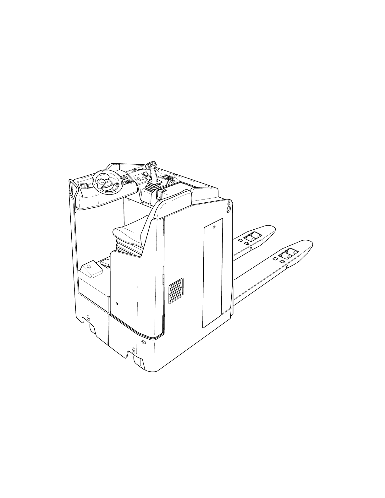
The EKE 20 b is an electric pallet truck with lateral seat in four-wheel design. It is provided with a driver's seat with electric steering wheel control.
The EKE 20 b is designed for transport and order-picking operations on level ground.
Pallets with open ground support or pallets fitted with lateral boards (provided that the
boards are outside the range of the load-bearing wheels) can be picked up.
The rated capacity of the truck is shown on the identification plate or on the capacity
label Qmax.
B 1
0402.GB
B Description of the truck
1 Design and application
The EKE 20 b is an electric pallet truck with lateral seat in four-wheel design. It is pro-
vided with a driver's seat with electric steering wheel control.
The EKE 20 b is designed for transport and order-picking operations on level ground.
Pallets with open ground support or pallets fitted with lateral boards (provided that the
boards are outside the range of the load-bearing wheels) can be picked up.
The rated capacity of the truck is shown on the identification plate or on the capacity
label Qmax.
Page 9

0402.GB
B 2
2 Assemblies
Item Designation Item Designation
1 t Information and service
indicator
7 t Battery door
2 t Control lever 8 t Seat hood
3 t Master switch (emerg. stop) 9 t Drive wheel
4 t Armrest 10 t Supporting wheel
5 t Battery hood 11 t Dead man's switch
6 t Lifting device 12 t Parking brake
t = Standard equipment o = Optional equipment
1 2 3 4
6
7
8
9
10
11
12
5
Page 10
B 3
0402.GB
2.1 Technical data - standard version
A
Indication of technical data according to VDI 2198,
subject to modification and supplementing.
2.2 Performance data
*
)
In case of longer forks, the load centre is in the fork centre.
Designation StandardtRapid drive
o
Q Rated capacity 2,000 2,000 kg
c Load centre distance 600 600 mm
Travelling speed
with / without rated load
7.7 / 10.0 9.5 / 12.5 km/h
Lifting speed
with / without rated load
8.0 / 12.0 8.0 / 12.0 cm/s
Lowering speed
with / without rated load
6.5 / 4.0 6.5 / 4.0 cm/s
Max. climbing capacity (5 min.)
with / without rated load
6 / 13 7 / 14 %
70
l
2
l
l
1
l
6
b
12
b
11
b5b
3
e
x
A
st3
h
13
h
3
h
7
b
1
155
y
95
30
c
Q
W
a
a
_
2
a
_
2
Page 11
0402.GB
B 4
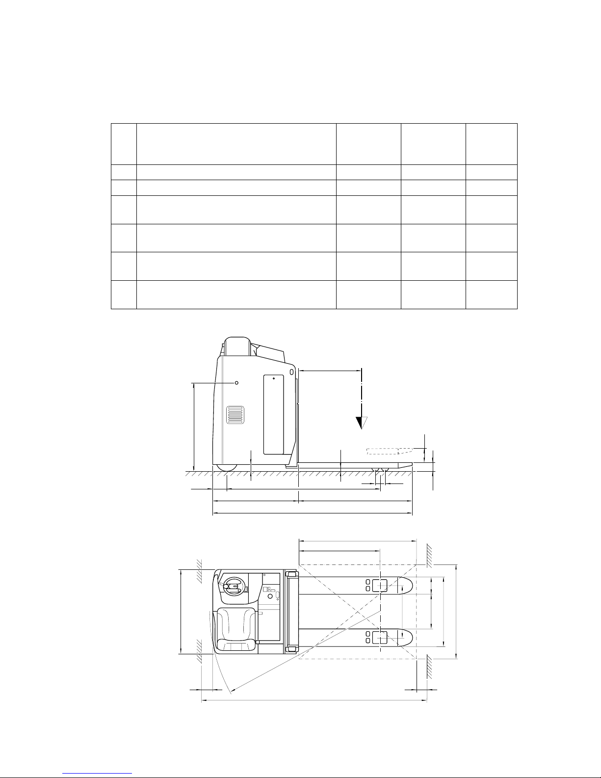
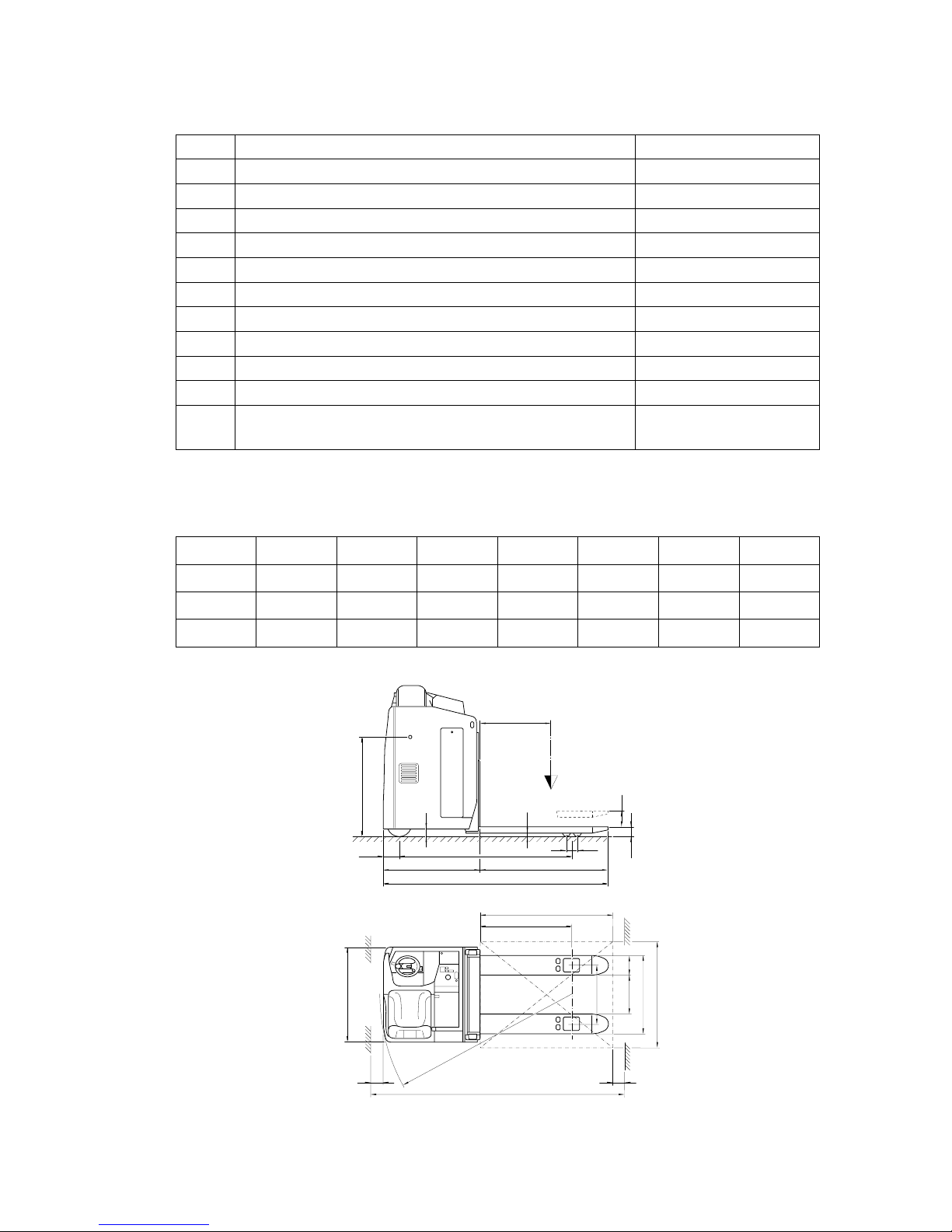
2.3 Dimensions
(all dimensions in mm)
Working aisle widths
(all dimensions in mm)
1)
With the load part lifted, the values are reduced by 90mm
Designation
l
2
Design length of front 880
h
13
Height of fork when lowered 90
h
3
Lift 125
h
7
Seat height 1,020
b
1
Truck width 950
b
5
Distance between forks, outside 510 / 540 / 670
b
11
Track 340 / 370 / 500
b
3
Distance between forks, inside 170 / 200 / 330
e Fork width 170
a Safety distance 200
Dead weight Refer to truck identifi-
cation label
ll1y
1)
x
1)
l
6
b
12
W
a
1)
A
st3
1,150 2,030 1,689 964 1,200 800 1,844 2,280
1,600 2,480 2,139 1,414 1,600 1,200 2,294 2,680
2,400 3,280 2,565 1,840 2,400 1,200 2,720 3,480
70
l
2
l
l
1
l
6
b
12
b
11
b5b
3
e
x
A
st3
h
13
h
3
h
7
b
1
155
y
95
30
c
Q
W
a
a
_
2
a
_
2
0402.GB
B 4
2.3 Dimensions
(all dimensions in mm)
Working aisle widths
(all dimensions in mm)
1)
With the load part lifted, the values are reduced by 90mm
Designation
l
2
Design length of front 880
h
13
Height of fork when lowered 90
h
3
Lift 125
h
7
Seat height 1,020
b
1
Truck width 950
b
5
Distance between forks, outside 510 / 540 / 670
b
11
Track 340 / 370 / 500
b
3
Distance between forks, inside 170 / 200 / 330
e Fork width 170
a Safety distance 200
Dead weight Refer to truck identifi-
cation label
ll1y
1)
x
1)
l
6
b
12
W
a
1)
A
st3
1,150 2,030 1,689 964 1,200 800 1,844 2,280
1,600 2,480 2,139 1,414 1,600 1,200 2,294 2,680
2,400 3,280 2,565 1,840 2,400 1,200 2,720 3,480
70
l
2
l
l
1
l
6
b
12
b
11
b5b
3
e
x
A
st3
h
13
h
3
h
7
b
1
155
y
95
30
c
Q
W
a
a
_
2
a
_
2
Page 12

B 5
0402.GB
2.4 EN standards
Continuous sound level: 68 dB(A)
according to prEN 12053 as stipulated in ISO 4871
A
The continuous sound level is a value averaged according to standard regulations,
taking the sound pressure level into account when driving, lifting and idling. The
sound pressure level is measured at the ear.
Vibration: 0.36 m/s
2
according to prEN 13059
A
The swinging acceleration acting on the body in its operating position is, according to
standard regulations, the linear integrated, weighted acceleration in the vertical
plane. It is determined by driving over bumps with a constant speed.
Electromagnetic compatibility (EMC)
The manufacturer confirms compliance with the limit values for electromagnetic emission and interference immunity as well as testing of static electricity discharge according to prEN 12895 and the references to other
standards contained therein.
A
Electrical or electronic components and their arrangement may only be modified after
written approval by the manufacturer has been obtained.
2.5 Conditions for application
Ambient temperature:
- during operation: 5°C to 40°C
A
Industrial trucks must be specially equipped and approved for continuous use in environments with temperatures below 5°C or in cold stores respectively with extreme
temperatures or humidity changes.
B 5
0402.GB
2.4 EN standards
Continuous sound level: 68 dB(A)
according to prEN 12053 as stipulated in ISO 4871
A
The continuous sound level is a value averaged according to standard regulations,
taking the sound pressure level into account when driving, lifting and idling. The
sound pressure level is measured at the ear.
Vibration: 0.36 m/s
2
according to prEN 13059
A
The swinging acceleration acting on the body in its operating position is, according to
standard regulations, the linear integrated, weighted acceleration in the vertical
plane. It is determined by driving over bumps with a constant speed.
Electromagnetic compatibility (EMC)
The manufacturer confirms compliance with the limit val-
ues for electromagnetic emission and interference immu-
nity as well as testing of static electricity discharge ac-
cording to prEN 12895 and the references to other
standards contained therein.
A
Electrical or electronic components and their arrangement may only be modified after
written approval by the manufacturer has been obtained.
2.5 Conditions for application
Ambient temperature:
- during operation: 5°C to 40°C
A
Industrial trucks must be specially equipped and approved for continuous use in en-
vironments with temperatures below 5°C or in cold stores respectively with extreme
temperatures or humidity changes.
Page 13
0402.GB
B 6
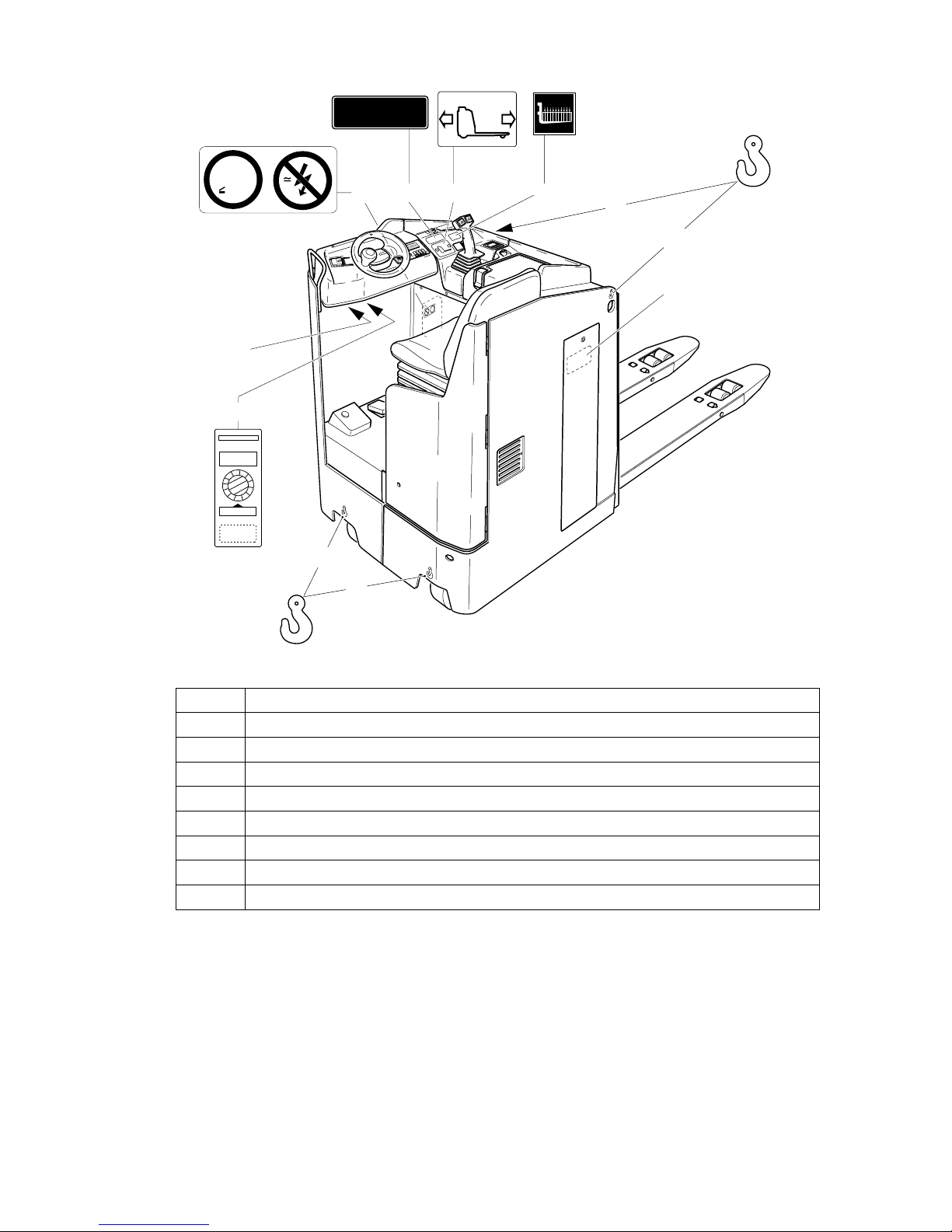
3 Location of instruction labels and identification labels
A
The capacity label (14) indicates the maximum capacity of the truck as Qmax. The
rated capacity as shown must not be exceeded.
The “Caution electronics and low voltage” warning signs (13) are visible after opening
the corresponding hood.
The battery identification plate (18) is visible after opening the battery hood and door
(refer to chapter D).
Item Designation
13 Label “CAUTION: Low-voltage electronics”
14 Capacity Qmax
15 Control lever
16 Floor load
17 Attachment point of hooks for transportation by crane
18 Battery identification plate
19 Accident prevention inspection label (D only)
20 Truck identification plate
mV
1,5 V
18
15 161413
19
Qmax 2000kg
20
17
17
1
2
1
1
1
0
9
8
7
6
5
4
3
2
1
2000
17
17
0402.GB
B 6
3 Location of instruction labels and identification labels
A
The capacity label (14) indicates the maximum capacity of the truck as Qmax. The
rated capacity as shown must not be exceeded.
The “Caution electronics and low voltage” warning signs (13) are visible after opening
the corresponding hood.
The battery identification plate (18) is visible after opening the battery hood and door
(refer to chapter D).
Item Designation
13 Label “CAUTION: Low-voltage electronics”
14 Capacity Qmax
15 Control lever
16 Floor load
17 Attachment point of hooks for transportation by crane
18 Battery identification plate
19 Accident prevention inspection label (D only)
20 Truck identification plate
mV
1,5 V
18
15 161413
19
Qmax 2000kg
20
17
17
1
2
1
1
1
0
9
8
7
6
5
4
3
2
1
2000
17
17
Page 14

B 7
0402.GB
3.1 Truck identification plate
A
In the event of queries relating to the truck or spare part orders, please state the serial
No. (22) of the truck.
Item Designation Item Designation
21 Type 28 Drive power
22 Serial No. 29 Customer no.
23 Rated capacity in kg 30 Min./max. battery weight in kg
24 Battery: Voltage V 31 Empty weight without battery in kg
25 Manufacturer 32 Year of manufacture
26 Order no. 33 Manufacturer logo
27 Load centre distance in mm
kg
kg mm kg
Xxx
Xxxx
Xxxxxxx
Xxxxxxxxx
Xxxxxxxxx
Xxxxxxxxxx
Xxxxx
Xxxx
Xxxxxxx
Xxxxxx
Xxxxxx
Xxxxxx
Xxxxxxxxxxxxxxxxxx
Xxxxxxxxxxxxxxxxxxx
Xxxxxxxxxxxxxxxxxxx
Xxxxxxxxxxxxxxxxx
VkW
Xxxxxxxxx
Xxxxxxxxxx
xxxxxxxxxx
xxxxxxxx
Xxxxxxxxxxxxxxxxxxx
Xxxxxxxxxxxxxxxxx
Xxxxxxxxxxxxxxxx
Xxxxxxxxxxxxxxxxxx
21
22
23
24
25
26
28
32
31
30
29
27
33
Page 15

0402.GB
B 8
0402.GB
B 8
Page 16
C 1
0402.GB
C Transportation and commissioning
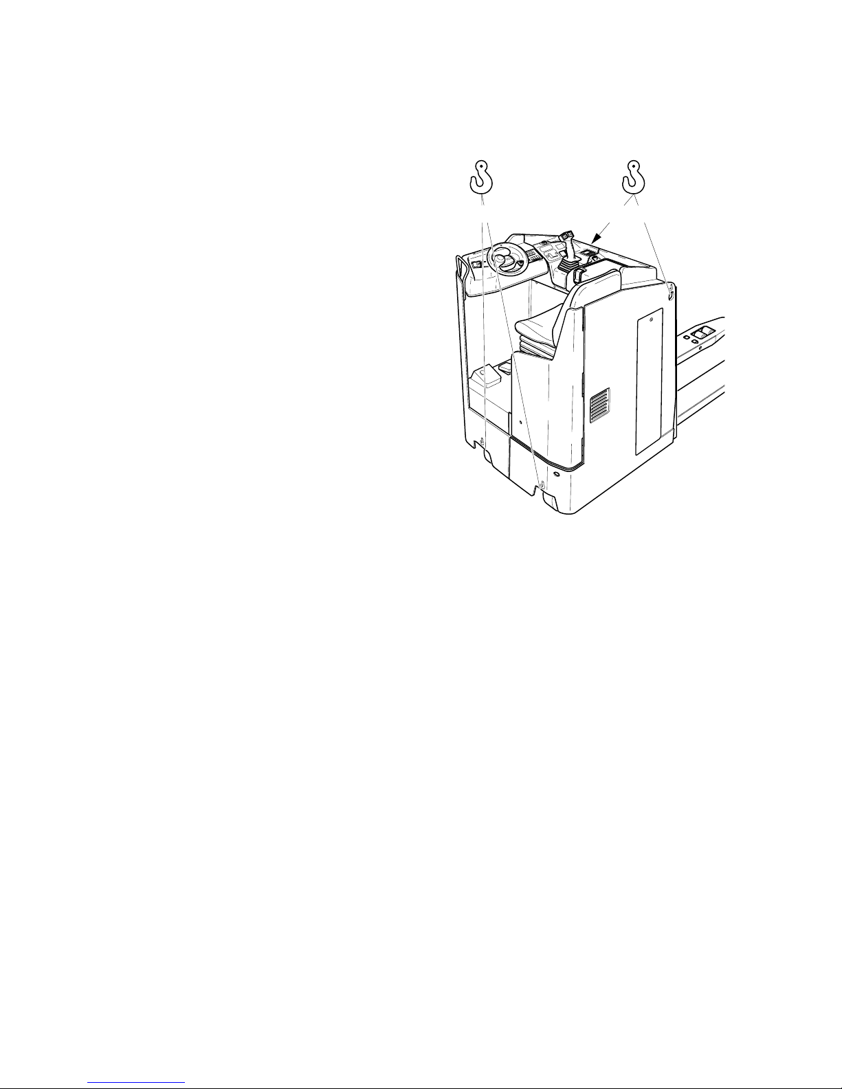
1 Transportation by crane
f
Only lifting gear of adequate capacity
must be used
(for the transport weight, refer to the
truck identification label).
A
Bore holes for lifting screws (1) and
hoisting points at the chassis (2) can be
used if hoisting gear is to be used for
transporting the truck.
– Park the truck and render it safe
(refer to chapter E).
– Screw the transportation screws (1)
into the bore holes of the single mast.
m
The lifting gear must be attached to the
attachment points in such a manner that
it absolutely cannot slip and cannot
come into contact with any attachments
of the truck when the truck is lifted.
2 Commissioning
m
The truck must only be operated on battery current. Rectified alternate current will
damage the electronics. Cables connected to the battery (trailing cables) must be
less than 6 meters in length.
In order to prepare the truck for work following delivery or transportation, the following
operations must be performed:
– Check the truck for completeness and satisfactory condition of the equipment.
– If necessary, install the battery. Do not damage the battery cable
(refer to chapter D)
– Charge the battery (refer to chapter D).
– Check whether the information and service indicator setting corresponds to the
used battery type (refer to chapter D).
– Commission the truck as detailed in chapter E).
A
When the truck is parked, the running surface of the tyres will flatten. The flattening
will disappear after a short operating time of the truck.
2 21
C 1
0402.GB
C Transportation and commissioning
1 Transportation by crane
f
Only lifting gear of adequate capacity
must be used
(for the transport weight, refer to the
truck identification label).
A
Bore holes for lifting screws (1) and
hoisting points at the chassis (2) can be
used if hoisting gear is to be used for
transporting the truck.
– Park the truck and render it safe
(refer to chapter E).
– Screw the transportation screws (1)
into the bore holes of the single mast.
m
The lifting gear must be attached to the
attachment points in such a manner that
it absolutely cannot slip and cannot
come into contact with any attachments
of the truck when the truck is lifted.
2 Commissioning
m
The truck must only be operated on battery current. Rectified alternate current will
damage the electronics. Cables connected to the battery (trailing cables) must be
less than 6 meters in length.
In order to prepare the truck for work following delivery or transportation, the following
operations must be performed:
– Check the truck for completeness and satisfactory condition of the equipment.
– If necessary, install the battery. Do not damage the battery cable
(refer to chapter D)
– Charge the battery (refer to chapter D).
– Check whether the information and service indicator setting corresponds to the
used battery type (refer to chapter D).
– Commission the truck as detailed in chapter E).
A
When the truck is parked, the running surface of the tyres will flatten. The flattening
will disappear after a short operating time of the truck.
2 21
Page 17

0402.GB
C 2
3 Moving the truck with the drive unit inoperative
f
This operating mode is not permitted when negotiating inclines and gradients.
If the truck has to be moved after a failure has rendered it immobile, proceed as follows:
– Set the master switch to position “OFF”.
– Set the key switch to position “OFF” (“0”) and remove
the key.
– Ensure that the truck cannot accidentally move.
– Open the seat hood
(refer to chapter F).
– Slacken the lock nuts (4) and tighten the screws (3).
The brake has now been released and the truck can be
moved.
f
After arriving at the repair bay, ensure that the brake is
put back to its initial state. The truck must on no account
be parked with the brake in the released condition.
– Loosen the screws (3) by approx. 5 mm and lock by
tightening the lock nuts (4).
The brake is now applied again.
– Close the seat hood.
4
3
0402.GB
C 2
3 Moving the truck with the drive unit inoperative
f
This operating mode is not permitted when negotiating inclines and gradients.
If the truck has to be moved after a failure has rendered it immobile, proceed as fol-
lows:
– Set the master switch to position “OFF”.
– Set the key switch to position “OFF” (“0”) and remove
the key.
– Ensure that the truck cannot accidentally move.
– Open the seat hood
(refer to chapter F).
– Slacken the lock nuts (4) and tighten the screws (3).
The brake has now been released and the truck can be
moved.
f
After arriving at the repair bay, ensure that the brake is
put back to its initial state. The truck must on no account
be parked with the brake in the released condition.
– Loosen the screws (3) by approx. 5 mm and lock by
tightening the lock nuts (4).
The brake is now applied again.
– Close the seat hood.
4
3
Page 18

D 1
0402.GB
D Battery - Servicing, recharging, replace-
ment
1 Safety regulations governing the handling of lead-acid batteries
The truck must be parked and rendered safe before any operations on batteries are
undertaken (refer to chapter E).
Servicing staff: Recharging, servicing and replacing of batteries must only be performed by qualified personnel. The instructions contained in this operating manual,
and the instructions of the manufacturer of the battery and of the battery recharging
station, must be observed when performing the above operations.
Fire protection measures: Smoking and naked flames are not permitted when handling batteries. No inflammable substances or spark-generating materials must be
present or stored within a distance of 2 meters of the truck parked for battery recharging. The location must be well ventilated and fire fighting equipment must be kept
ready.
Servicing of batteries: The battery cell screw caps must be kept dry and clean. Terminals and cable shoes must be clean, lightly greased with pole grease and must be
securely tightened. Batteries with bare terminal posts must be covered using a nonskid insulating mat.
Disposal of the battery: Batteries must only be disposed of as stipulated in the national environmental protection regulations or waste disposal provisions. The manufacturer’s specifications for the disposal must be heeded.
m
Before closing the battery hood, make sure that the battery cable cannot be damaged.
f
Batteries contain dissolved acid which is toxic and caustic. For this reason, protective
clothing and goggles must be worn whenever work is undertaken on batteries. Avoid
physical contact with battery acid.
If clothing, skin or eyes accidentally come into contact with battery acid, liberally flush
the affected parts with clean water. Consult a doctor when skin or eyes come into contact with battery acid. Spilled battery acid must be immediately neutralized.
m
Only batteries with closed tray may be used.
f
Battery weight and dimensions have considerable influence on operational safety of
the truck. Changing the battery equipment is not permitted without prior approval by
the manufacturer.
D 1
0402.GB
D Battery - Servicing, recharging, replace-
ment
1 Safety regulations governing the handling of lead-acid batteries
The truck must be parked and rendered safe before any operations on batteries are
undertaken (refer to chapter E).
Servicing staff: Recharging, servicing and replacing of batteries must only be per-
formed by qualified personnel. The instructions contained in this operating manual,
and the instructions of the manufacturer of the battery and of the battery recharging
station, must be observed when performing the above operations.
Fire protection measures: Smoking and naked flames are not permitted when han-
dling batteries. No inflammable substances or spark-generating materials must be
present or stored within a distance of 2 meters of the truck parked for battery recharg-
ing. The location must be well ventilated and fire fighting equipment must be kept
ready.
Servicing of batteries: The battery cell screw caps must be kept dry and clean. Ter-
minals and cable shoes must be clean, lightly greased with pole grease and must be
securely tightened. Batteries with bare terminal posts must be covered using a non-
skid insulating mat.
Disposal of the battery: Batteries must only be disposed of as stipulated in the na-
tional environmental protection regulations or waste disposal provisions. The manu-
facturer’s specifications for the disposal must be heeded.
m
Before closing the battery hood, make sure that the battery cable cannot be dam-
aged.
f
Batteries contain dissolved acid which is toxic and caustic. For this reason, protective
clothing and goggles must be worn whenever work is undertaken on batteries. Avoid
physical contact with battery acid.
If clothing, skin or eyes accidentally come into contact with battery acid, liberally flush
the affected parts with clean water. Consult a doctor when skin or eyes come into con-
tact with battery acid. Spilled battery acid must be immediately neutralized.
m
Only batteries with closed tray may be used.
f
Battery weight and dimensions have considerable influence on operational safety of
the truck. Changing the battery equipment is not permitted without prior approval by
the manufacturer.
Page 19

0402.GB
D 2
2Battery types
Depending on the truck version, the truck will be supplied with different battery types.
The table below shows the capacity of the batteries and also the combinations used
as standard equipment.
The battery weights can be seen on the battery identification plate.
Depending on the type of battery used, it is also possible to use models with enhanced performance or maintenance-free batteries.
m
When replacing or installing batteries, ensure that the battery is correctly secured in
the battery compartment of the truck.
3 Exposing the battery
f
Park the truck and render it safe (refer to
chapter E).
– Use the hex key located beneath the
armrest (2) (see chapter F) to open the
battery door (5), take out the door and
put it aside.
– Pull the unlocking lever (1) for the bat-
tery hood (3).
– Swing up the battery hood (3) and en-
gage it.
f
Open and close the battery hood carefully.
Connecting and disconnecting of battery
connector and socket is only permitted
when the truck and the charger are both
switched off.
24V - PzS - Battery 3 PzS 330L (with weights)
24V - PzS - Battery 3 PzS 420L
24V - PzS - Battery performance-enhanced 3 PzS 450HX
1 2
4
5
3
0402.GB
D 2
2Battery types
Depending on the truck version, the truck will be supplied with different battery types.
The table below shows the capacity of the batteries and also the combinations used
as standard equipment.
The battery weights can be seen on the battery identification plate.
Depending on the type of battery used, it is also possible to use models with en-
hanced performance or maintenance-free batteries.
m
When replacing or installing batteries, ensure that the battery is correctly secured in
the battery compartment of the truck.
3 Exposing the battery
f
Park the truck and render it safe (refer to
chapter E).
– Use the hex key located beneath the
armrest (2) (see chapter F) to open the
battery door (5), take out the door and
put it aside.
– Pull the unlocking lever (1) for the bat-
tery hood (3).
– Swing up the battery hood (3) and en-
gage it.
f
Open and close the battery hood care-
fully.
Connecting and disconnecting of battery
connector and socket is only permitted
when the truck and the charger are both
switched off.
24V - PzS - Battery 3 PzS 330L (with weights)
24V - PzS - Battery 3 PzS 420L
24V - PzS - Battery performance-enhanced 3 PzS 450HX
1 2
4
5
3
Page 20

D 3
0402.GB
4 Charging the battery
f
To charge the battery, the truck must be parked in a closed and properly ventilated
room.
– Expose the battery (refer section 3).
m
The battery connector (6) and the charging cable must only be connected or disconnected with the truck and the battery charger switched off. The master switch must
also only be actuated with the truck and the battery charger switched off.
f
During the recharging operation, the tops of the battery cells must be exposed to ensure adequate ventilation. No metal objects must be placed on the battery. Prior to
starting the recharging operation, check all cable connections and plugged connections for visible damage.
All safety instructions as provided by the battery supplier and battery charger supplier
must be strictly observed.
– Withdraw the battery connector (6).
– Remove any insulating mats from the battery.
– Connect the charging cable of the battery charger to the battery connector (6) and
switch on the charger.
m
Recharge the battery observing the instructions provided by the battery supplier and
by the battery charger supplier.
6
D 3
0402.GB
4 Charging the battery
f
To charge the battery, the truck must be parked in a closed and properly ventilated
room.
– Expose the battery (refer section 3).
m
The battery connector (6) and the charging cable must only be connected or discon-
nected with the truck and the battery charger switched off. The master switch must
also only be actuated with the truck and the battery charger switched off.
f
During the recharging operation, the tops of the battery cells must be exposed to en-
sure adequate ventilation. No metal objects must be placed on the battery. Prior to
starting the recharging operation, check all cable connections and plugged connec-
tions for visible damage.
All safety instructions as provided by the battery supplier and battery charger supplier
must be strictly observed.
– Withdraw the battery connector (6).
– Remove any insulating mats from the battery.
– Connect the charging cable of the battery charger to the battery connector (6) and
switch on the charger.
m
Recharge the battery observing the instructions provided by the battery supplier and
by the battery charger supplier.
6
Page 21

0402.GB
D 4
5 Removing and installing the battery
f
The truck must be parked on level ground. To prevent short-circuits, batteries with exposed poles or cell connectors must be covered using a rubber mat. Place the battery
connector or the battery cable, respectively, in such a way that they will not catch behind any truck protrusions when the battery is withdrawn.
m
When transporting batteries with the aid of a crane, ensure that the crane is of adequate capacity (the battery weight is indicated on the battery identification plate at the
battery trough). The lifting gear must pull in a vertical direction to prevent damage to
the battery trough. The lifting gear hooks must be secured to the attachment points in
such a way that the lifting gear, when slack, cannot collapse on the battery cells.
– Expose the battery (refer section 3).
– Withdraw the battery connector (6).
– Open the battery door (5) with the hex key.
A
The square key is located under the armrest
(refer to chapter F).
– Remove the red battery lock (8).
– Pull the battery (7) laterally onto the battery change station.
f
Heed the operating instructions of the manufacturer of the battery exchange trolley!
Installation is in the reverse order of operations. When reinstalling the battery, heed
the required installation position and make sure the battery is connected correctly.
f
After reinstallation of the
battery, visually check all
leads and connectors for
damage.
Ensure that the battery is
firmly secured in the truck to
prevent any damage
caused by sudden movements of the truck. Make
sure that the red battery lock
(8) is properly attached.
The battery hood and door
must be properly closed.
7
8
0402.GB
D 4
5 Removing and installing the battery
f
The truck must be parked on level ground. To prevent short-circuits, batteries with ex-
posed poles or cell connectors must be covered using a rubber mat. Place the battery
connector or the battery cable, respectively, in such a way that they will not catch be-
hind any truck protrusions when the battery is withdrawn.
m
When transporting batteries with the aid of a crane, ensure that the crane is of ade-
quate capacity (the battery weight is indicated on the battery identification plate at the
battery trough). The lifting gear must pull in a vertical direction to prevent damage to
the battery trough. The lifting gear hooks must be secured to the attachment points in
such a way that the lifting gear, when slack, cannot collapse on the battery cells.
– Expose the battery (refer section 3).
– Withdraw the battery connector (6).
– Open the battery door (5) with the hex key.
A
The square key is located under the armrest
(refer to chapter F).
– Remove the red battery lock (8).
– Pull the battery (7) laterally onto the battery change station.
f
Heed the operating instructions of the manufacturer of the battery exchange trolley!
Installation is in the reverse order of operations. When reinstalling the battery, heed
the required installation position and make sure the battery is connected correctly.
f
After reinstallation of the
battery, visually check all
leads and connectors for
damage.
Ensure that the battery is
firmly secured in the truck to
prevent any damage
caused by sudden move-
ments of the truck. Make
sure that the red battery lock
(8) is properly attached.
The battery hood and door
must be properly closed.
7
8
Page 22

D 5
0402.GB
6 Battery discharge indicator, battery discharge monitor, operating hour meter
Battery discharge indicator: The loading status of the battery (8) is indicated in
steps of 10% on the information and service indicator.
m
The manufacturer setting of the battery
discharge indicator / discharge monitor
is standard batteries.
If maintenance-free batteries are used,
the indicator must be adjusted in such a
way that the “T” symbol (9) appears behind the percent specification. If this setting is not selected the battery may be
damaged due to a complete discharge.
Contact the customer service for setting
the instrument.
If the remaining battery capacity falls below 30%, it is required to recharge the
battery.
Battery discharge monitor: If the residual capacity falls below the specified minimum value, the lifting function is switched off. A corresponding message is displayed
in the information and service indicator.
A
The lifting function will only then be released, if the connected battery is reloaded by
min. 70%.
Operating hour meter: The operating hours (10) are indicated next to the loading
status of the battery. The operating hour meter indicates the total time of all riding and
lifting movements.
BATT T:0 0%4471h
8
9
10
D 5
0402.GB
6 Battery discharge indicator, battery discharge monitor, operating hour meter
Battery discharge indicator: The loading status of the battery (8) is indicated in
steps of 10% on the information and service indicator.
m
The manufacturer setting of the battery
discharge indicator / discharge monitor
is standard batteries.
If maintenance-free batteries are used,
the indicator must be adjusted in such a
way that the “T” symbol (9) appears be-
hind the percent specification. If this set-
ting is not selected the battery may be
damaged due to a complete discharge.
Contact the customer service for setting
the instrument.
If the remaining battery capacity falls be-
low 30%, it is required to recharge the
battery.
Battery discharge monitor: If the residual capacity falls below the specified mini-
mum value, the lifting function is switched off. A corresponding message is displayed
in the information and service indicator.
A
The lifting function will only then be released, if the connected battery is reloaded by
min. 70%.
Operating hour meter: The operating hours (10) are indicated next to the loading
status of the battery. The operating hour meter indicates the total time of all riding and
lifting movements.
BATT T:0 0%4471h
8
9
10
Page 23

0402.GB
D 6
0402.GB
D 6
Page 24

E 1
0402.GB
E Operation
1 Safety regulations governing the operation of the fork-lift truck
Driving permission: The fork-lift truck must only be operated by persons who have
been trained in the operation of trucks, who have demonstrated to the user or his representative their capability of moving and handling loads, and who have expressly
been charged by the user or his representative with the operation of the truck.
Rights, duties and conduct of the driver: The driver must be: informed of his rights
and duties; trained in the operation of the fork-lift truck; and familiar with the contents
of these operating instructions. All necessary rights must be granted to him.
If the fork-lift truck can be used in the pedestrian-controlled mode, the driver must
wear safety boots when operating the truck.
Prohibition of unauthorised use: The driver is responsible for the fork-lift truck during working time. He must forbid unauthorised persons to drive or operate the fork-lift
truck. The transport or lifting of persons is forbidden.
Damage and defects: Damage or defects noted on the fork-lift truck or on the attachments must immediately be brought to the notice of the person in charge. Fork-lift
trucks that cannot be safely operated (e.g. due to worn tyres or defective brakes)
must not be used until they have been properly repaired.
Repairs: Without specific training and express authorisation, the driver is not allowed
to perform any repairs or modifications on the fork-lift truck. Under no circumstances
must the driver change the setting of switches or safety installations or render them
ineffective.
Danger area: A “danger area” is considered to be the area within which persons are
endangered by the travelling or lifting movements of the fork-lift truck or its load lifting
devices (e.g. fork or attachments), or by the loads being transported. This also includes the area within reach of falling loads or falling/lowering truck attachments.
f
Unauthorised persons must be asked to leave the danger area. The driver must give
a warning signal whenever a situation presenting danger to persons might develop.
The fork-lift truck must immediately be brought to a standstill if persons, although
asked, do not leave the danger area.
Safety devices and warning labels: The safety devices, warning labels and warning
notes described in the present operating instructions must always be heeded.
E 1
0402.GB
E Operation
1 Safety regulations governing the operation of the fork-lift truck
Driving permission: The fork-lift truck must only be operated by persons who have
been trained in the operation of trucks, who have demonstrated to the user or his rep-
resentative their capability of moving and handling loads, and who have expressly
been charged by the user or his representative with the operation of the truck.
Rights, duties and conduct of the driver: The driver must be: informed of his rights
and duties; trained in the operation of the fork-lift truck; and familiar with the contents
of these operating instructions. All necessary rights must be granted to him.
If the fork-lift truck can be used in the pedestrian-controlled mode, the driver must
wear safety boots when operating the truck.
Prohibition of unauthorised use: The driver is responsible for the fork-lift truck dur-
ing working time. He must forbid unauthorised persons to drive or operate the fork-lift
truck. The transport or lifting of persons is forbidden.
Damage and defects: Damage or defects noted on the fork-lift truck or on the attach-
ments must immediately be brought to the notice of the person in charge. Fork-lift
trucks that cannot be safely operated (e.g. due to worn tyres or defective brakes)
must not be used until they have been properly repaired.
Repairs: Without specific training and express authorisation, the driver is not allowed
to perform any repairs or modifications on the fork-lift truck. Under no circumstances
must the driver change the setting of switches or safety installations or render them
ineffective.
Danger area: A “danger area” is considered to be the area within which persons are
endangered by the travelling or lifting movements of the fork-lift truck or its load lifting
devices (e.g. fork or attachments), or by the loads being transported. This also in-
cludes the area within reach of falling loads or falling/lowering truck attachments.
f
Unauthorised persons must be asked to leave the danger area. The driver must give
a warning signal whenever a situation presenting danger to persons might develop.
The fork-lift truck must immediately be brought to a standstill if persons, although
asked, do not leave the danger area.
Safety devices and warning labels: The safety devices, warning labels and warning
notes described in the present operating instructions must always be heeded.
Page 25

0402.GB
E 2
2 Description of the operating controls and indicators
Item Operating control or display Function
1 Key switch t Switches the control current on and off.
When the key is removed from the key
switch, the truck cannot be operated by unauthorised persons.
2 Control lamp -
driver seat heating
o Shows, when alight, that the driver seat
heating is ON.
3 Lamp indicating that the
truck is operational
t Shows, when alight, that the control current
in ON.
4 Operating key “Horn” t Gives an audible warning signal.
5 Operating key “Lowering” t Lowers the lifting device.
6 Operating key “Lifting” t Lifts the lifting device.
7 Control lever t Sets the desired travelling direction.
8 Switch - driver seat heating o Switches the driver seat heating ON and
OFF.
9 Master switch
(emergency stop)
t The circuit is interrupted, all electrical func-
tions are switched off and the truck is automatically braked.
10 Deadman key t released: Driving function blocked or
truck is slowing down
operated: Driving function released
11 Brake pedal t Braking of the truck.
12 Adjusting wheel for seat
damping
t Sets the driver weight for optimum damping
effect. The set weight is indicated.
13 Adjusting wheel for back-
rest
t Adjustment of the driver seat backrest.
14 Driver seat locking mecha-
nism
t Horizontal adjustment of the driver seat.
15 Switch - parking brake t Applies or releases the parking brake.
17 Control lamp - parking
brake
t Shows, when alight, that the parking brake
is applied.
17 Information and service
indicator
t Indicates important driving and lifting pa-
rameters, warning messages, notes on operation faults and service information
(refer section 5).
t = Standard equipment o = Optional equipment
0402.GB
E 2
2 Description of the operating controls and indicators
Item Operating control or display Function
1 Key switch t Switches the control current on and off.
When the key is removed from the key
switch, the truck cannot be operated by un-
authorised persons.
2 Control lamp -
driver seat heating
o Shows, when alight, that the driver seat
heating is ON.
3 Lamp indicating that the
truck is operational
t Shows, when alight, that the control current
in ON.
4 Operating key “Horn” t Gives an audible warning signal.
5 Operating key “Lowering” t Lowers the lifting device.
6 Operating key “Lifting” t Lifts the lifting device.
7 Control lever t Sets the desired travelling direction.
8 Switch - driver seat heating o Switches the driver seat heating ON and
OFF.
9 Master switch
(emergency stop)
t The circuit is interrupted, all electrical func-
tions are switched off and the truck is auto-
matically braked.
10 Deadman key t released: Driving function blocked or
truck is slowing down
operated: Driving function released
11 Brake pedal t Braking of the truck.
12 Adjusting wheel for seat
damping
t Sets the driver weight for optimum damping
effect. The set weight is indicated.
13 Adjusting wheel for back-
rest
t Adjustment of the driver seat backrest.
14 Driver seat locking mecha-
nism
t Horizontal adjustment of the driver seat.
15 Switch - parking brake t Applies or releases the parking brake.
17 Control lamp - parking
brake
t Shows, when alight, that the parking brake
is applied.
17 Information and service
indicator
t Indicates important driving and lifting pa-
rameters, warning messages, notes on op-
eration faults and service information
(refer section 5).
t = Standard equipment o = Optional equipment
Page 26

E 3
0402.GB
1 2 3 4
11
10
14
5 6 7
9
13
12
17
16
15
8
E 3
0402.GB
1 2 3 4
11
10
14
5 6 7
9
13
12
17
16
15
8
Page 27

0402.GB
E 4
3 Starting up the truck
f
Before starting or operating the truck, or before lifting any loads, the driver has to
make sure that nobody is within the danger area.
The electronic driving and steering systems automatically control their functions. If an
error or fault occurs, the driving and steering functions are stopped.
f
Before the truck is restarted, it is required to perform the relevant troubleshooting actions.
Checks and operations to be performed before starting daily work
– Visually check the entire truck (especially the wheels and the lifting device) for vis-
ible damage.
– Visually check the battery attachment and the cable connections.
f
Do not actuate the control lever when entering the truck.
Adjusting the driver seat
f
Do not reach into the rear wall of the truck
when adjusting the driver’s seat.
– Sit down on the seat.
– Release the driver seat locking mecha-
nism (14) and slide the seat forward or
backward to the desired position.
– Allow the locking mechanism to reen-
gage.
– Using the adjusting wheel (12), adjust
the seat damping system to the driver
weight.
– Adjust the backrest by means of the
backrest adjusting mechanism (13).
121314
0402.GB
E 4
3 Starting up the truck
f
Before starting or operating the truck, or before lifting any loads, the driver has to
make sure that nobody is within the danger area.
The electronic driving and steering systems automatically control their functions. If an
error or fault occurs, the driving and steering functions are stopped.
f
Before the truck is restarted, it is required to perform the relevant troubleshooting ac-
tions.
Checks and operations to be performed before starting daily work
– Visually check the entire truck (especially the wheels and the lifting device) for vis-
ible damage.
– Visually check the battery attachment and the cable connections.
f
Do not actuate the control lever when entering the truck.
Adjusting the driver seat
f
Do not reach into the rear wall of the truck
when adjusting the driver’s seat.
– Sit down on the seat.
– Release the driver seat locking mecha-
nism (14) and slide the seat forward or
backward to the desired position.
– Allow the locking mechanism to reen-
gage.
– Using the adjusting wheel (12), adjust
the seat damping system to the driver
weight.
– Adjust the backrest by means of the
backrest adjusting mechanism (13).
121314
Page 28

E 5
0402.GB
Switching on the truck
– Pull up the master switch (9).
– Insert the key in the key switch (1) and turn the key clockwise towards the “I” posi-
tion until reaching the stop.
– Check the horn (4) for correct functioning.
– Check whether the deadman key (10), brake pedal (11), “Parking brake” switch
(15) and control lever (7) are properly functioning (refer section 4.2).
The truck is now ready for operation.
A
The information and service indicator (17) briefly displays the vehicle code, followed
by the current steering position of the drive wheel, the available battery capacity and
the hours of operation.
17
1 4
9
11
15
7
10
Page 29

0402.GB
E 6
4 Operation of the fork-lift truck
4.1 Safety regulations applicable when operating the truck
Driving lanes and work areas: Only such lanes and routes that are specially allo-
cated for truck traffic must be used. Unauthorised persons must stay away from work
areas. Loads must only be stored at places specially provided for this purpose.
Driving conduct: The travelling speed must be adapted to the prevailing local conditions. The truck must be driven at slow speed when negotiating bends or narrow
passages, when passing through swing doors and at blind spots. The driver must always observe an adequate braking distance between the fork-lift truck and the vehicle in front and he must be in control of his truck at all times. Sudden stopping (except
in emergencies), rapid U-turns and overtaking at dangerous or blind spots is not permitted. It is forbidden to lean out of or reach beyond the working and operating area.
Visibility: The driver must look in the direction of travel and must always have a clear
view of the route ahead. When loads blocking the view are carried, the fork-lift truck
must be driven with the load at the rear. If this is not possible, a second person must
walk in front of the fork-lift truck to give suitable warnings.
Negotiating slopes and inclines: Negotiating of slopes and inclines is permitted
only when they are recognised lanes, when they are clean and non-slipping, and
when the technical specification of the truck permits safe driving on such slopes or
inclines. Loads must always be carried at that end of the truck facing uphill. U-turns,
cutting obliquely over slopes or inclines and parking of the fork-lift truck on slopes or
inclines is not permitted. Inclines must only be negotiated at slow speed, with the driver ready to brake at any moment.
Use of lifts and driving on loading platforms: Lifts and loading platforms must only
be used if they are of adequate load bearing capacity, if suitable for driving on, and if
authorised by the user of the truck for truck traffic. The fork-lift truck driver has to satisfy himself accordingly before driving into lifts or on to loading platforms. The truck
must enter lifts with the load in front and must take up a position which does not allow
it to come into contact with the walls of the lift shaft. Persons riding in the lift together
with the fork-lift truck must only enter the lift after the fork-lift truck has come safely to
a standstill, and must leave the lift before the fork-lift truck.
Nature of the loads carried: Only loads that have been safely and correctly secured
must be carried. Never transport loads stacked higher than the top of the fork carriage, or stacked higher than the guard grille.
Towing trailers: The maximum trailer load given for the fork-lift truck for braked and/
or unbraked trailers must not be exceeded. The trailer load must be properly secured
and must not exceed the dimensions permitted for the driving routes. After attaching
the trailer but before starting driving, the driver must check that the trailer attachment
is secured against detachment. Towing fork-lift trucks must be operated in such a
manner that safe driving and braking of the truck and the trailer is guaranteed for all
driving movements.
0402.GB
E 6
4 Operation of the fork-lift truck
4.1 Safety regulations applicable when operating the truck
Driving lanes and work areas: Only such lanes and routes that are specially allo-
cated for truck traffic must be used. Unauthorised persons must stay away from work
areas. Loads must only be stored at places specially provided for this purpose.
Driving conduct: The travelling speed must be adapted to the prevailing local con-
ditions. The truck must be driven at slow speed when negotiating bends or narrow
passages, when passing through swing doors and at blind spots. The driver must al-
ways observe an adequate braking distance between the fork-lift truck and the vehi-
cle in front and he must be in control of his truck at all times. Sudden stopping (except
in emergencies), rapid U-turns and overtaking at dangerous or blind spots is not per-
mitted. It is forbidden to lean out of or reach beyond the working and operating area.
Visibility: The driver must look in the direction of travel and must always have a clear
view of the route ahead. When loads blocking the view are carried, the fork-lift truck
must be driven with the load at the rear. If this is not possible, a second person must
walk in front of the fork-lift truck to give suitable warnings.
Negotiating slopes and inclines: Negotiating of slopes and inclines is permitted
only when they are recognised lanes, when they are clean and non-slipping, and
when the technical specification of the truck permits safe driving on such slopes or
inclines. Loads must always be carried at that end of the truck facing uphill. U-turns,
cutting obliquely over slopes or inclines and parking of the fork-lift truck on slopes or
inclines is not permitted. Inclines must only be negotiated at slow speed, with the driv-
er ready to brake at any moment.
Use of lifts and driving on loading platforms: Lifts and loading platforms must only
be used if they are of adequate load bearing capacity, if suitable for driving on, and if
authorised by the user of the truck for truck traffic. The fork-lift truck driver has to sat-
isfy himself accordingly before driving into lifts or on to loading platforms. The truck
must enter lifts with the load in front and must take up a position which does not allow
it to come into contact with the walls of the lift shaft. Persons riding in the lift together
with the fork-lift truck must only enter the lift after the fork-lift truck has come safely to
a standstill, and must leave the lift before the fork-lift truck.
Nature of the loads carried: Only loads that have been safely and correctly secured
must be carried. Never transport loads stacked higher than the top of the fork car-
riage, or stacked higher than the guard grille.
Towing trailers: The maximum trailer load given for the fork-lift truck for braked and/
or unbraked trailers must not be exceeded. The trailer load must be properly secured
and must not exceed the dimensions permitted for the driving routes. After attaching
the trailer but before starting driving, the driver must check that the trailer attachment
is secured against detachment. Towing fork-lift trucks must be operated in such a
manner that safe driving and braking of the truck and the trailer is guaranteed for all
driving movements.
Page 30

E 7
0402.GB
4.2 Driving, steering, braking
f
Increased attention has to be paid during driving and steering the truck.
Control the steering position of the drive wheel on the information and service indicator (17).
The electric steering system is self-monitoring.
The steering control systems monitors the fault frequency over a certain period. If the
same fault is detected several times during this period, the steering control reduces
the driving speed of the truck to low speed. If such a fault occurs, the driving speed
is not reset to normal speed by switching the truck off and on again. This method prevents the cancellation of a fault without eliminating the fault.
f
As the steering system is a safety-relevant component, the fault must be eliminated
by trained service personnel.
Emergency stop
– Depress the master switch (9).
This will switch off all electric functions.
Deadman key
The deadman key (10) must be operated for all operating functions. If it is not applied,
all functions (exception: the information and service indicator (17)) are deactivated
and the brake is operated.
Driving
f
Do not drive the truck unless the hoods are closed and locked in the stipulated manner.
– Start up the truck (refer section 3).
– Operate the deadman key (10).
– Release the parking brake by depressing the parking brake switch (15).
f
Control the steering position of the drive wheel on the information and service indicator (17).
– Set the control lever (7) to the desired travelling direction (V) or (R).
The truck will move in the selected direction.
A
The travelling speed is controlled by means of the control lever (7).
E 7
0402.GB
4.2 Driving, steering, braking
f
Increased attention has to be paid during driving and steering the truck.
Control the steering position of the drive wheel on the information and service indica-
tor (17).
The electric steering system is self-monitoring.
The steering control systems monitors the fault frequency over a certain period. If the
same fault is detected several times during this period, the steering control reduces
the driving speed of the truck to low speed. If such a fault occurs, the driving speed
is not reset to normal speed by switching the truck off and on again. This method pre-
vents the cancellation of a fault without eliminating the fault.
f
As the steering system is a safety-relevant component, the fault must be eliminated
by trained service personnel.
Emergency stop
– Depress the master switch (9).
This will switch off all electric functions.
Deadman key
The deadman key (10) must be operated for all operating functions. If it is not applied,
all functions (exception: the information and service indicator (17)) are deactivated
and the brake is operated.
Driving
f
Do not drive the truck unless the hoods are closed and locked in the stipulated man-
ner.
– Start up the truck (refer section 3).
– Operate the deadman key (10).
– Release the parking brake by depressing the parking brake switch (15).
f
Control the steering position of the drive wheel on the information and service indica-
tor (17).
– Set the control lever (7) to the desired travelling direction (V) or (R).
The truck will move in the selected direction.
A
The travelling speed is controlled by means of the control lever (7).
Page 31

0402.GB
E 8
Driving up an incline
m
The load must be transported facing the incline!
Safety measures against “rolling down” of the truck:
With the control lever (7) set to neutral, the service brake is automatically applied after
a brief jolt (the controller detects the truck’s rolling down on an incline). The control
lever (7) is used to release the service brake; the speed and driving direction are set
as desired.
m
When the service personnel has switched off the coast-down brake, only the service
and/or the counter-current brake can be used.
Steering
– Turn the steering wheel to the left or to the right.
A
The position of the steered wheel is displayed on the information and service indicator
(17).
17
9
15
10
7
R
R
V
V
Page 32

E 9
0402.GB
Braking
f
The braking behaviour of the truck strongly depends on the state of the floor. This
must be taken into account by the driver for his driving behaviour.
The truck may be braked in three ways:
– using the service brake (break pedal (11))
– using the generator brake (coasting)
– by counter-current braking (control lever (7))
f
In case of emergencies, the truck must only be braked using the service brake (break
pedal (11)).
A
During normal operation, the generator brake and counter-current braking should be
applied. These methods of braking reduce wear and require less energy (energy recovery.
Braking by means of the service brake:
– Depress the brake pedal (11).
The truck is braked at the maximum possible deceleration rate until it stands still.
15
10
11
7
E 9
0402.GB
Braking
f
The braking behaviour of the truck strongly depends on the state of the floor. This
must be taken into account by the driver for his driving behaviour.
The truck may be braked in three ways:
– using the service brake (break pedal (11))
– using the generator brake (coasting)
– by counter-current braking (control lever (7))
f
In case of emergencies, the truck must only be braked using the service brake (break
pedal (11)).
A
During normal operation, the generator brake and counter-current braking should be
applied. These methods of braking reduce wear and require less energy (energy re-
covery.
Braking by means of the service brake:
– Depress the brake pedal (11).
The truck is braked at the maximum possible deceleration rate until it stands still.
15
10
11
7
Page 33

0402.GB
E 10
Braking by means of the generator brake (coasting)
– Release the control lever (7) - control lever to neutral.
Depending on the setting, the truck is braked by the generator braked, coasting to a
stop.
A
The degree of speed reduction can be set by the manufacturer service.
m
When the service personnel has switched off the coast-down brake, only the service
and/or the counter-current brake can be used.
Counter-current braking
– Setting the control lever (7) to the opposite drive direction while travelling.
The truck is braked by counter-current until it starts moving into the opposite direction.
A
The braking effect depends on the setting of the control lever.
4.3 Picking up and setting down loads
m
Before picking up a load, the driver has to make sure that it is correctly palletised and
that the capacity of the truck is not exceeded.
– Pass the lifting device as far as possible under the load. Picking up long loads
crosswise is not permitted.
m
Pick up the load, ensuring that it does not project excessively from the tips of the lifting
device (less than 50 mm).
Lifting and lowering
A
When operating the keys “Lifting” or
“Lowering”, the lifting or lowering movement will be at a fixed speed.
The deadman key (10) must be operated.
Lifting
– Depress operating key “Lifting” (6) until
the required lifting height has been
reached.
Lowering
– Depress operating key “Lowering” (5);
the fork is lowered.
5
6
0402.GB
E 10
Braking by means of the generator brake (coasting)
– Release the control lever (7) - control lever to neutral.
Depending on the setting, the truck is braked by the generator braked, coasting to a
stop.
A
The degree of speed reduction can be set by the manufacturer service.
m
When the service personnel has switched off the coast-down brake, only the service
and/or the counter-current brake can be used.
Counter-current braking
– Setting the control lever (7) to the opposite drive direction while travelling.
The truck is braked by counter-current until it starts moving into the opposite direction.
A
The braking effect depends on the setting of the control lever.
4.3 Picking up and setting down loads
m
Before picking up a load, the driver has to make sure that it is correctly palletised and
that the capacity of the truck is not exceeded.
– Pass the lifting device as far as possible under the load. Picking up long loads
crosswise is not permitted.
m
Pick up the load, ensuring that it does not project excessively from the tips of the lifting
device (less than 50 mm).
Lifting and lowering
A
When operating the keys “Lifting” or
“Lowering”, the lifting or lowering move-
ment will be at a fixed speed.
The deadman key (10) must be operated.
Lifting
– Depress operating key “Lifting” (6) until
the required lifting height has been
reached.
Lowering
– Depress operating key “Lowering” (5);
the fork is lowered.
5
6
Page 34

E 11
0402.GB
4.4 Safe parking of the truck
If the truck is left unattended, even for only short periods of time, it must be rendered
safe.
f
Never park the truck on a slope or incline. The lifting device must always be completely lowered.
– Operate the parking brake switch (15).
– Lower the lifting device.
– Set the drive wheel to the “straight ahead position”.
Turn the steering wheel until the drive wheel is set to its straight ahead position.
A
Control the displayed steering angle on the information and service indicator (17).
– Switch the key switch (1) to position “OFF” (“0”) and remove the key.
– Depress the master switch (emergency cut-out) (9) to the “OFF” position.
17
1 4
9
11
15
7
10
E 11
0402.GB
4.4 Safe parking of the truck
If the truck is left unattended, even for only short periods of time, it must be rendered
safe.
f
Never park the truck on a slope or incline. The lifting device must always be complete-
ly lowered.
– Operate the parking brake switch (15).
– Lower the lifting device.
– Set the drive wheel to the “straight ahead position”.
Turn the steering wheel until the drive wheel is set to its straight ahead position.
A
Control the displayed steering angle on the information and service indicator (17).
– Switch the key switch (1) to position “OFF” (“0”) and remove the key.
– Depress the master switch (emergency cut-out) (9) to the “OFF” position.
17
1 4
9
11
15
7
10
Page 35

0402.GB
E 12
5 Information and service indicator (LISA)
The LCD display (19) of the LISA information and service indicator indicates
the battery charge status (18), the operating hours (21) and the position of the
steered wheel (20). The operating data
is shown in the service and diagnosis
mode (refer section 5.3).
Two light-emitting diodes (LED (22) (23)) below the display are used as indicators. The keyboard, four keys, (24) (27), is needed to select, read or modify
truck parameters.
m
In the service mode, only authorised personnel of the manufacturer service may perform modifications!
5.1 LED indicators
Two lit LED indicators show the following states:
5.2 Keyboard assignment
Item. Function
22 Driving direction forward (direction of the drive) (green LED)
23 Driving direction backwards (direction of the load) (green LED)
Item. Function
24 Double function
– increase of the selected parameter in steps
– Selection of the individual menu items in upward direction
25 Double function
– decrease of the selected parameter in steps
– Selection of the individual menu items in downward direction
26 Double function
– Release of a selection menu from the main menu
– Confirmation of a question with “NO” -> “x”
27 Quadruple function
– Quitting a selected menu item
– Saving a modified parameter
– Confirmation of a question with “YES” -> “q”
– Change between “operating hours” and “time” indication
BATT : 1 0%020h
19
20
21
18
25
2322 2624 27
0402.GB
E 12
5 Information and service indicator (LISA)
The LCD display (19) of the LISA infor-
mation and service indicator indicates
the battery charge status (18), the oper-
ating hours (21) and the position of the
steered wheel (20). The operating data
is shown in the service and diagnosis
mode (refer section 5.3).
Two light-emitting diodes (LED (22) -
(23)) below the display are used as indi-
cators. The keyboard, four keys, (24) -
(27), is needed to select, read or modify
truck parameters.
m
In the service mode, only authorised personnel of the manufacturer service may per-
form modifications!
5.1 LED indicators
Two lit LED indicators show the following states:
5.2 Keyboard assignment
Item. Function
22 Driving direction forward (direction of the drive) (green LED)
23 Driving direction backwards (direction of the load) (green LED)
Item. Function
24 Double function
– increase of the selected parameter in steps
– Selection of the individual menu items in upward direction
25 Double function
– decrease of the selected parameter in steps
– Selection of the individual menu items in downward direction
26 Double function
– Release of a selection menu from the main menu
– Confirmation of a question with “NO” -> “x”
27 Quadruple function
– Quitting a selected menu item
– Saving a modified parameter
– Confirmation of a question with “YES” -> “q”
– Change between “operating hours” and “time” indication
BATT : 1 0%020h
19
20
21
18
25
2322 2624 27
Page 36

E 13
0402.GB
5.3 Indicators
Operating data and error messages are displayed on the indicator. The operator
menu can be used to set the following truck parameters:
ACCELERATION
L
Here, the interval between maximum controller actuation
and 100% adjustment of the electronics is set.
This driving parameter has no function.
RELEASE BRAKE
L
INVERSION BRAKE
L
PEDAL BRAKE
L
MAX SPEED FORW.
L
CUT BACK FORW.
L
MAX REVERS.SPEED
L
BUZZER ON/OFF
OFF L
RELOAD
L
Issues an audible alarm in case of an operating fault.
This setting has no function.
This driving parameter may only be adjusted by the custom service.
This driving parameter has no function.
This driving parameter may only be adjusted by the custom service.
This driving parameter has no function.
his driving parameter may only be adjusted by the cus-
om service.
CHANGE TIME
12 :22L
Setting the time: Select the required hours and minutes
with key (26). Use keys (24) and (25) to correct the entered
values.
E 13
0402.GB
5.3 Indicators
Operating data and error messages are displayed on the indicator. The operator
menu can be used to set the following truck parameters:
ACCELERATION
L
Here, the interval between maximum controller actuation
and 100% adjustment of the electronics is set.
This driving parameter has no function.
RELEASE BRAKE
L
INVERSION BRAKE
L
PEDAL BRAKE
L
MAX SPEED FORW.
L
CUT BACK FORW.
L
MAX REVERS.SPEED
L
BUZZER ON/OFF
OFF L
RELOAD
L
Issues an audible alarm in case of an operating fault.
This setting has no function.
This driving parameter may only be adjusted by the cus-
tom service.
This driving parameter has no function.
This driving parameter may only be adjusted by the cus-
tom service.
This driving parameter has no function.
his driving parameter may only be adjusted by the cus-
om service.
CHANGE TIME
12 :22L
Setting the time: Select the required hours and minutes
with key (26). Use keys (24) and (25) to correct the entered
values.
Page 37

0402.GB
E 14
5.4 Changing driving parameters
f
The driving behaviour of the truck is changed if the truck parameters are modified.
This is to be taken into consideration during start-up!
Parameters may only be modified with the truck parked and while it is not performing
any lifting movements.
– Commissioning the truck (refer section 3).
– Put the key into the key switch and turn it right until stop.
The operator menu is displayed for approx. 3 sec., indicating the truck designation.
Then, the current steering angle, the battery charging status and the operating hours
are indicated.
– Key Press selection menu key (26).
The indicator displays “acceleration” with the corresponding parameter.
– Proceed as indicated in the following diagram, if you want to check or modify any
truck parameters.
– Use the following keys to change between the adjustment parameters: (30) and
(24) and (25).
Acceleration
L
1)
Setting the time
XX:XX L
1)
Buzzer on/off
OFF L
1)
Low-speed ride
Load direction L
1)
Speed
Load direction L
1)
Low-speed ride
Direction of the drive L
1)
Speed
Direction of the drive L
1)
Reverse brake
L
3)
Coasting brake
L
1)
Acceleration
S
2)
Setting the time
XX:XX S
2)
Buzzer on/off
ON/OFF S
2
)
Low-speed ride
Load direction S
3)
Speed
Load direction S
2)
Low-speed ride
Direction of the drive S
3)
Speed
Direction of the drive S
2)
Reverse brake
S
3)
Coasting brake
S
2)
yes
Change?
no
BATT xxx% xx h
4)
1)
L = Read operating parameters (Read mode).
2)
S = Change operating parameters (Write mode) using the keys .
3)
no function
4
Indicator "Operating hours"
6)
Parameter selection indicator
5)
Indicator "Time“
7)
Change of parameters
BATT xxx% xx:xx
5)
Basic setting
Default val. for "driving“ L
3)
Basic setting
Default val. for "driving“ S
3
)
6)
7)
Page 38

E 15
0402.GB
6 Fault location
This chapter enables the operator to locate and rectify minor faults and malfunctions,
or the effects of operating errors. When trying to locate a fault, proceed in the order
shown in the table.
A
If it is not possible to rectify the fault by performing the indicated remedial actions,
please contact the customer service, as more intricate faults can only be rectified by
specially trained and qualified service personnel.
Fault Possible cause Remedial action
Truck does
not move
– Battery connector not con-
nected.
– Master switch (emergency
stop) depressed.
– Key switch in position “0”.
– Battery exhausted.
– The deadman’s key has not
been pressed.
– Fuse defective.
– Check the battery connector and
connect if necessary.
– Release the master switch.
– Set the key switch to position “I”.
– Check the charging condition of the
battery and recharge if necessary.
– Press the deadman’s key
– Check fuses F1, 1F1 and 3F9.
Load
cannot be
lifted
– Truck not operative.
– Hydraulic oil level too low.
– Battery discharge monitor
has switched off the lifting
function and indicates
“STOP”.
– Fuse defective.
– Load is too heavy.
– Perform all remedial actions listed
under the fault “Truck does not
move”.
– Check the hydraulic oil level.
– Recharge the battery.
– Check fuse 2F1.
– Heed the maximum capacity
(see the identification plate).
Page 39

0402.GB
E 16
0402.GB
E 16
Page 40

F 1
0402.GB
F Maintenance of the fork lift truck
1 Operational safety and environmental protection
The checks and servicing operations contained in this chapter must be performed in
accordance with the intervals as indicated in the servicing checklists.
f
Modifications of fork lift truck assemblies, especially of the safety installations, are not
permitted. On no account must the operational speeds of the truck be changed.
m
Only original spare parts have been certified by our quality assurance service. To ensure safe and reliable operation of the fork lift truck, only spare parts of the manufacturer must be used. Used parts, oils and fuels must be disposed of in accordance with
the applicable environmental protection regulations. For oil changes, the oil service
of the manufacturer is available to you.
Upon completion of any checking and servicing activities, the operations contained in
the section “Recommissioning” must be performed (refer to chapter F).
2 Safety regulations applicable to truck maintenance
Servicing and maintenance personnel: The fork lift truck must only be serviced and
maintained by trained personnel of the manufacturer. The service organization of the
manufacturer has external technicians trained especially for these assignments. We
thus recommend signing a maintenance contract with the relevant service location of
the manufacturer.
Lifting and jacking up: When a fork lift truck is to be lifted, the lifting gear must only
be secured to the points specially provided for this purpose. When the truck is to be
jacked up, suitable measures must be taken to prevent the truck from slipping or tipping over (use of wedges, wooden blocks). Work underneath the raised load lifting
device must only be carried out when the fork is immobilised and supported by a
chain of adequate strength.
Cleaning operations: No inflammable liquids must be used when cleaning the fork
lift truck. Prior to commencing cleaning operations, all safety measures that are required to prevent sparking (e.g. by short-circuits) have to be taken. For battery-operated fork lift trucks, the battery plug must be removed. Only weak indraft, weak compressed air and non-conducting, antistatic brushes must be used for the cleaning of
electric or electronic assemblies.
m
If the fork lift truck is to be cleaned using a water jet or a high-pressure cleaner, all
electric and electronic components must be carefully covered beforehand because
moisture can lead to incorrect functioning.
Cleaning by means of a steam jet is not permitted.
Upon completion of cleaning work, the operations detailed in the section “Recommissioning” must be performed.
F 1
0402.GB
F Maintenance of the fork lift truck
1 Operational safety and environmental protection
The checks and servicing operations contained in this chapter must be performed in
accordance with the intervals as indicated in the servicing checklists.
f
Modifications of fork lift truck assemblies, especially of the safety installations, are not
permitted. On no account must the operational speeds of the truck be changed.
m
Only original spare parts have been certified by our quality assurance service. To en-
sure safe and reliable operation of the fork lift truck, only spare parts of the manufac-
turer must be used. Used parts, oils and fuels must be disposed of in accordance with
the applicable environmental protection regulations. For oil changes, the oil service
of the manufacturer is available to you.
Upon completion of any checking and servicing activities, the operations contained in
the section “Recommissioning” must be performed (refer to chapter F).
2 Safety regulations applicable to truck maintenance
Servicing and maintenance personnel: The fork lift truck must only be serviced and
maintained by trained personnel of the manufacturer. The service organization of the
manufacturer has external technicians trained especially for these assignments. We
thus recommend signing a maintenance contract with the relevant service location of
the manufacturer.
Lifting and jacking up: When a fork lift truck is to be lifted, the lifting gear must only
be secured to the points specially provided for this purpose. When the truck is to be
jacked up, suitable measures must be taken to prevent the truck from slipping or tip-
ping over (use of wedges, wooden blocks). Work underneath the raised load lifting
device must only be carried out when the fork is immobilised and supported by a
chain of adequate strength.
Cleaning operations: No inflammable liquids must be used when cleaning the fork
lift truck. Prior to commencing cleaning operations, all safety measures that are re-
quired to prevent sparking (e.g. by short-circuits) have to be taken. For battery-oper-
ated fork lift trucks, the battery plug must be removed. Only weak indraft, weak com-
pressed air and non-conducting, antistatic brushes must be used for the cleaning of
electric or electronic assemblies.
m
If the fork lift truck is to be cleaned using a water jet or a high-pressure cleaner, all
electric and electronic components must be carefully covered beforehand because
moisture can lead to incorrect functioning.
Cleaning by means of a steam jet is not permitted.
Upon completion of cleaning work, the operations detailed in the section “Recommis-
sioning” must be performed.
Page 41

0402.GB
F 2
Work on the electric system: Work on the electric system of the truck must only be
performed by personnel specially trained for such operations. Before commencing
any work on the electric system, all measures required to prevent electric shocks
have to be taken. For battery-operated fork lift trucks, the truck must also be depowered by removing the battery plug.
Welding operations: To prevent any damage to electric or electronic components,
these have to be removed from the fork lift truck before any welding operations are
undertaken.
Settings: When repairing or replacing hydraulic, electric or electronic components or
assemblies, all truck-specific settings have to be retained.
Tyres: The quality of the tyres greatly affects the stability and the driving behaviour
of the fork-lift truck. The factory-mounted tyres must only be replaced by original
spare parts of the manufacturer, since otherwise the specification of the data sheet
cannot be met. When replacing wheels or tyres, it must be ensured that the fork-lift
truck remains level (tyres and wheels must always be replaced in pairs, i.e. left and
right together).
Lift chains: The lift chains wear rapidly if not lubricated. The intervals in the service
checklist apply to normal duty. If requirements are higher (dust, temperature), lubrication is required more often. The specified chain spray must be used as specified.
The external application of grease does not provide sufficient lubrication.
Hydraulic hoses: The hoses must be renewed every six years. When replacing hydraulic components, also renew the hoses in this hydraulic system.
0402.GB
F 2
Work on the electric system: Work on the electric system of the truck must only be
performed by personnel specially trained for such operations. Before commencing
any work on the electric system, all measures required to prevent electric shocks
have to be taken. For battery-operated fork lift trucks, the truck must also be depow-
ered by removing the battery plug.
Welding operations: To prevent any damage to electric or electronic components,
these have to be removed from the fork lift truck before any welding operations are
undertaken.
Settings: When repairing or replacing hydraulic, electric or electronic components or
assemblies, all truck-specific settings have to be retained.
Tyres: The quality of the tyres greatly affects the stability and the driving behaviour
of the fork-lift truck. The factory-mounted tyres must only be replaced by original
spare parts of the manufacturer, since otherwise the specification of the data sheet
cannot be met. When replacing wheels or tyres, it must be ensured that the fork-lift
truck remains level (tyres and wheels must always be replaced in pairs, i.e. left and
right together).
Lift chains: The lift chains wear rapidly if not lubricated. The intervals in the service
checklist apply to normal duty. If requirements are higher (dust, temperature), lubri-
cation is required more often. The specified chain spray must be used as specified.
The external application of grease does not provide sufficient lubrication.
Hydraulic hoses: The hoses must be renewed every six years. When replacing hy-
draulic components, also renew the hoses in this hydraulic system.
Page 42

F 3
0402.GB
3 Servicing and inspection
Thorough and expert servicing is one of the most important preconditions for safe operation of the fork-lift truck. The neglect of regular servicing intervals can lead to forklift truck failure and constitutes a potential hazard to personnel and equipment.
m
The indicated servicing intervals are based on single-shift operation under normal operating conditions. For applications in dusty environments, or involving large temperature fluctuations or multiple-shift operation, the servicing intervals must be
shortened accordingly.
The following servicing checklist indicates the operations to be performed and the respective intervals to be observed. The servicing intervals are defined as follows:
W1 = every 50 operating hours, but at least once per week
M3 = every 500 operating hours, but at least every 3 months
M6 = every 1000 operating hours, but at least every 6 months
M12 = every 2000 operating hours, but at least every 12 months
A
The W1 maintenance intervals must be carried out by the operator / customer.
In the running-in phase of the truck, the following additional operations have to be carried out:
After the first 50 to 100 operating hours, at the latest after two months:
– Tighten pole screws of battery and check condition of the cell connectors.
– Perform visual inspection of the electronic and mechanic components.
– Check the brake fluid.
– Check the lifting chains for even tension.
– Check transmission for leakages.
– Check screw connections and mechanical safety retentions for tight fit.
– Check the wheel nuts for security and retighten, if required.
– Check the hydraulic connections for leakages and retighten, if necessary.
– Check the slide elements on the mast and adjust, if necessary.
F 3
0402.GB
3 Servicing and inspection
Thorough and expert servicing is one of the most important preconditions for safe op-
eration of the fork-lift truck. The neglect of regular servicing intervals can lead to fork-
lift truck failure and constitutes a potential hazard to personnel and equipment.
m
The indicated servicing intervals are based on single-shift operation under normal op-
erating conditions. For applications in dusty environments, or involving large temper-
ature fluctuations or multiple-shift operation, the servicing intervals must be
shortened accordingly.
The following servicing checklist indicates the operations to be performed and the re-
spective intervals to be observed. The servicing intervals are defined as follows:
W1 = every 50 operating hours, but at least once per week
M3 = every 500 operating hours, but at least every 3 months
M6 = every 1000 operating hours, but at least every 6 months
M12 = every 2000 operating hours, but at least every 12 months
A
The W1 maintenance intervals must be carried out by the operator / customer.
In the running-in phase of the truck, the following additional operations have to be car-
ried out:
After the first 50 to 100 operating hours, at the latest after two months:
– Tighten pole screws of battery and check condition of the cell connectors.
– Perform visual inspection of the electronic and mechanic components.
– Check the brake fluid.
– Check the lifting chains for even tension.
– Check transmission for leakages.
– Check screw connections and mechanical safety retentions for tight fit.
– Check the wheel nuts for security and retighten, if required.
– Check the hydraulic connections for leakages and retighten, if necessary.
– Check the slide elements on the mast and adjust, if necessary.
Page 43

0402.GB
F 4
4 Maintenance checklist
Maintenance intervals
Standard = t WMMM
Cold-storage depot = k 13612
Chassis/
Design:
1.1 Check all load bearing elements for damage t
1.2 Check all bolted connections t
1.3 Check platform for correct functioning and damage kt
Drive unit: 2.1 Check the transmission for noises and leakage t
2.2 Check the transmission oil level t
2.3 Change the transmission oil kt
Wheels: 3.1 Check for wear and damage t
3.2 Check the wheel bearings and ensure
secure fastening of wheels a)
kt
Steering: 4.1 Check the steering wheel play t
4.2 Check the steering chain and the chain
sprocket for wear; adjust and grease c)
kt
4.3 Replace “actual value” steering angle potentiometer (on
the steering motor)
t
kt
Brake
system:
5.1 Performance and adjustment check t
5.2 Check the brake linings for wear t
5.3 Check reset function of the brake pedal kt
5.4 Check the brake linkage; adjust if necessary t
Lifting device:
7.1 Check performance, wear and adjustment t
7.2 Perform a visual check of rollers, sliding elements, and
stops
lt
7.3 Check the fork tines and fork carrier for wear and damage
kt
Hydr. system: 8.1 Performance check kt
8.2 Check all connections for leakage and damage b) kt
8.3 Check hydraulic cylinders for leakage, damage and secure attachment
t
8.4 Clean filter kt
8.5 Check the oil level kt
8.6 Change hydraulic oil d) kt
8.7 Check the pressure relief valves for correct functioning t
0402.GB
F 4
4 Maintenance checklist
Maintenance intervals
Standard = t WMMM
Cold-storage depot = k 13612
Chassis/
Design:
1.1 Check all load bearing elements for damage t
1.2 Check all bolted connections t
1.3 Check platform for correct functioning and damage kt
Drive unit: 2.1 Check the transmission for noises and leakage t
2.2 Check the transmission oil level t
2.3 Change the transmission oil kt
Wheels: 3.1 Check for wear and damage t
3.2 Check the wheel bearings and ensure
secure fastening of wheels a)
kt
Steering: 4.1 Check the steering wheel play t
4.2 Check the steering chain and the chain
sprocket for wear; adjust and grease c)
kt
4.3 Replace “actual value” steering angle potentiometer (on
the steering motor)
t
kt
Brake
system:
5.1 Performance and adjustment check t
5.2 Check the brake linings for wear t
5.3 Check reset function of the brake pedal kt
5.4 Check the brake linkage; adjust if necessary t
Lifting de-
vice:
7.1 Check performance, wear and adjustment t
7.2 Perform a visual check of rollers, sliding elements, and
stops
lt
7.3 Check the fork tines and fork carrier for wear and dam-
age
kt
Hydr. system: 8.1 Performance check kt
8.2 Check all connections for leakage and damage b) kt
8.3 Check hydraulic cylinders for leakage, damage and se-
cure attachment
t
8.4 Clean filter kt
8.5 Check the oil level kt
8.6 Change hydraulic oil d) kt
8.7 Check the pressure relief valves for correct functioning t
Page 44

F 5
0402.GB
a) Wheel bolts to be first checked for tightness after approx. 100 operating hours,
tighten, if necessary.
b) Hydraulic connections to be first checked for leakage after approx. 100 operating
hours; tighten, if necessary.
c) Check the steering chain tension for the first time after ca. 100 operating hours and adjust,
if necessary.
d) First change after 500 operating hours.
A
The maintenance intervals refer to normal service conditions. In case of aggravated
conditions, the intervals must be reduced as required.
Maintenance intervals
Standard = t WMMM
Cold-storage depot = k 13612
Electrical system:
9.1 Performance check t
9.2 Check all cables for secure connection and damage t
9.3 Check the fuses for correct amperage t
9.4 Check switches and trip cams for secure attachment
and correct functioning
t
9.5 Check the warning installations and safety circuits for
correct functioning
kt
9.6 Check contactors, replace wearing parts if necessary t
Electric motors:
10.1 Check the carbon brushes for wear t
10.2 Check the motor for secure attachment t
10.3 Clean motor housing by means of a vacuum cleaner and
check the commutator for wear
kt
10.4 Check whether the cover of the steering-engine potentiometer is present.
Battery: 11.1 Check acid density, acid level and cell voltage kt
11.2 Check the terminals for secure attachment and apply
grease
kt
11.3 Clean battery connections, check for tight seat kt
11.4 Check the battery cables for damage, renew, if necessary
t
11.5 Check whether the battery lock is fully functioning t
Lubrication: 12.1 Grease the vehicle in accordance with the lubrication
schedule
kt
General
measurements:
13.1 Check the electrical system for a grounding fault t
13.2 Check the driving speed and braking distance t
13.3 Check the lifting and lowering speed t
13.4 Check safety and shutdown devices t
Demonstration:
14.1 Perform a trial run under a nominal load t
14.2 Upon completion of servicing operations, demonstrate
the vehicle to the person responsible
kt
F 5
0402.GB
a) Wheel bolts to be first checked for tightness after approx. 100 operating hours,
tighten, if necessary.
b) Hydraulic connections to be first checked for leakage after approx. 100 operating
hours; tighten, if necessary.
c) Check the steering chain tension for the first time after ca. 100 operating hours and adjust,
if necessary.
d) First change after 500 operating hours.
A
The maintenance intervals refer to normal service conditions. In case of aggravated
conditions, the intervals must be reduced as required.
Maintenance intervals
Standard = t WMMM
Cold-storage depot = k 13612
Electrical sys-
tem:
9.1 Performance check t
9.2 Check all cables for secure connection and damage t
9.3 Check the fuses for correct amperage t
9.4 Check switches and trip cams for secure attachment
and correct functioning
t
9.5 Check the warning installations and safety circuits for
correct functioning
kt
9.6 Check contactors, replace wearing parts if necessary t
Electric mo-
tors:
10.1 Check the carbon brushes for wear t
10.2 Check the motor for secure attachment t
10.3 Clean motor housing by means of a vacuum cleaner and
check the commutator for wear
kt
10.4 Check whether the cover of the steering-engine potenti-
ometer is present.
Battery: 11.1 Check acid density, acid level and cell voltage kt
11.2 Check the terminals for secure attachment and apply
grease
kt
11.3 Clean battery connections, check for tight seat kt
11.4 Check the battery cables for damage, renew, if neces-
sary
t
11.5 Check whether the battery lock is fully functioning t
Lubrication: 12.1 Grease the vehicle in accordance with the lubrication
schedule
kt
General
measure-
ments:
13.1 Check the electrical system for a grounding fault t
13.2 Check the driving speed and braking distance t
13.3 Check the lifting and lowering speed t
13.4 Check safety and shutdown devices t
Demon-
stration:
14.1 Perform a trial run under a nominal load t
14.2 Upon completion of servicing operations, demonstrate
the vehicle to the person responsible
kt
Page 45

0402.GB
F 6
5 Lubrication schedule
g Gliding surfaces
s Grease nipples
Filler plug for hydraulic oil
b Filler plug for gear oil
a Drain plug for gear oil
Cold store usage
1)
Compound for cold store usage 1:1
2)
1.25l - 1.3l; depending on the drive type (always up to the lower edge of
the filler neck).
s s
E
a
B
1,25 - 1,3 l
B + C
b
1)
g
A + C
A
0,7 l
1)
F
G
Page 46

F 7
0402.GB
5.1 Fuels, coolants and lubricants
Handling consumption type material: Consumption type material must always be
handled properly. Manufacturer's instructions are to be observed.
f
Improper handling is injurious to health, life, and environment. Consumption type materials must be stored in adequate containers. They might be inflammable and, therefore, must not come into contact with hot components or open fire.
When filling in consumption type materials use clean containers only. It is prohibited
to mix consumption type materials of different grades or qualities, except if mixing is
expressively prescribed in these operating instructions.
Avoid spilling. Spilt liquid must be removed immediately using a suitable binding
agent, and the mixture of consumption type material and binding agent is to be disposed of according to the regulations.
Grease data
Code Order No. Supply Qty Designation Used for:
A 29 200 670 5.0 l H-LP 46, DIN 51524 Hydraulic system
B 29 200 680 5.0 l CLP 100, DIN 51517 Transmission
C 29 200 810 5.0 l H-LP 10, DIN 51524 Transmission,
hydraulic system
E 29 201 430 1.0 kg Grease, DIN 51825 Lubrication
F 29 200 100 1.0 kg Grease, TTF52 Lubrication
Code Saponifica-
tion
Dropp. point
°C
Worked
penetr. at 25 °C
NLG1 class Service tem-
perat. °C
E Lithium 185 265 - 295 2 -35 / +120
F — — 310 - 340 1 -52 / +100
F 7
0402.GB
5.1 Fuels, coolants and lubricants
Handling consumption type material: Consumption type material must always be
handled properly. Manufacturer's instructions are to be observed.
f
Improper handling is injurious to health, life, and environment. Consumption type ma-
terials must be stored in adequate containers. They might be inflammable and, there-
fore, must not come into contact with hot components or open fire.
When filling in consumption type materials use clean containers only. It is prohibited
to mix consumption type materials of different grades or qualities, except if mixing is
expressively prescribed in these operating instructions.
Avoid spilling. Spilt liquid must be removed immediately using a suitable binding
agent, and the mixture of consumption type material and binding agent is to be dis-
posed of according to the regulations.
Grease data
Code Order No. Supply Qty Designation Used for:
A 29 200 670 5.0 l H-LP 46, DIN 51524 Hydraulic system
B 29 200 680 5.0 l CLP 100, DIN 51517 Transmission
C 29 200 810 5.0 l H-LP 10, DIN 51524 Transmission,
hydraulic system
E 29 201 430 1.0 kg Grease, DIN 51825 Lubrication
F 29 200 100 1.0 kg Grease, TTF52 Lubrication
Code Saponifica-
tion
Dropp. point
°C
Worked
penetr. at 25 °C
NLG1 class Service tem-
perat. °C
E Lithium 185 265 - 295 2 -35 / +120
F — — 310 - 340 1 -52 / +100
Page 47

0402.GB
F 8
6 Instructions for the servicing operations
6.1 Preparing the truck for servicing and maintenance operations
All required safety measures must be taken to prevent any accidents in the course of
the servicing and maintenance operations. The following preparatory operations
must be performed:
– Park the truck and render it safe (refer to chapter E).
– Disconnect the battery plug to prevent accidental starting of the truck
(refer to chapter D)
f
When work has to be performed under the jacked-up truck, suitable measures must
be taken to prevent any dropping, tilting or slipping of the truck. When lifting the truck,
the instructions contained in the chapter “Transportation and commissioning” have to
be observed.
6.2 Tilting up the armrest
– Pull up the release (1).
The armrest (2) will swivel upwards.
A
The hex key is now accessible.
21
Page 48

F 9
0402.GB
6.3 Opening the battery hood
– Use the service key to unlock the battery hood (3).
– Swing the battery hood (4) upward and lock it.
6.4 Opening the seat hood
– Use the hex key located beneath the armrest (2) to open the seat hood (5).
– Swing the seat hood (6) to the outside.
A
Drive unit, steering motor, steering control and the hydraulic installation can be easily
accessed for maintenance works.
3
4
8
7
6
5
Page 49

0402.GB
F 10
6.5 Opening the control flap
– Open the latch (9) with the hex key (located beneath the armrest (2)).
– Take out the control flap (10) and put it aside.
A
The drive current control system and the truck fuses are readily accessible for servicing purposes.
f
Do not drive the truck unless the hoods are closed and locked in the stipulated manner.
9
10
0402.GB
F 10
6.5 Opening the control flap
– Open the latch (9) with the hex key (located beneath the armrest (2)).
– Take out the control flap (10) and put it aside.
A
The drive current control system and the truck fuses are readily accessible for serv-
icing purposes.
f
Do not drive the truck unless the hoods are closed and locked in the stipulated man-
ner.
9
10
Page 50

F 11
0402.GB
6.6 Tightening the wheel screws
The wheel screws of the drive wheel must be retightened in accordance with the servicing intervals indicated in the servicing checklist.
– Position the drive wheel (12) at right angles to the longitudinal axis of the truck.
– Tighten all wheel-fixing bolts (10) using a wrench which is to be inserted through
the opening (13) of the collision guard.
A
Tightening torque
– 1st step - MA = 10 Nm
– 2nd step - MA = 105 Nm
m
Remove the wrench after tightening the wheel-fixing bolts.
11
13
12
F 11
0402.GB
6.6 Tightening the wheel screws
The wheel screws of the drive wheel must be retightened in accordance with the serv-
icing intervals indicated in the servicing checklist.
– Position the drive wheel (12) at right angles to the longitudinal axis of the truck.
– Tighten all wheel-fixing bolts (10) using a wrench which is to be inserted through
the opening (13) of the collision guard.
A
Tightening torque
– 1st step - MA = 10 Nm
– 2nd step - MA = 105 Nm
m
Remove the wrench after tightening the wheel-fixing bolts.
11
13
12
Page 51

0402.GB
F 12
6.7 Checking the electric fuses
– Prepare the truck for the servicing and maintenance operations
(refer to chapter F, section 6.1).
– Open the hoods (refer to chapter F, section 6.3 and 6.4).
– Referring to the table, check all fuses for correct rating and damage; replace fuses
where required.
– Reclose the hoods
(refer to chapter F, section 6.3 and 6.4).
Item. Designation Protection of: Value
14 3F9 Steering motor 30 A
15 1F1 Pump motor 150 A
16 2F1 Drive motor 150 A
17 1F10 Field “Driving” 40 A
18 6F2 Battery discharge indicator /
operating hour meter
10 A
19 F1 Entire control circuit 10 A
15
14
17
16
18
19
Page 52

F 13
0402.GB
6.8 Recommissioning the truck
Recommissioning of the truck following the performance of cleaning or maintenance
work is permitted only after the following operations have been performed:
– Check the horn for proper functioning.
– Check the master switch for correct functioning.
– Check the brake for correct functioning.
– Lubricate truck according to lubrication schedule.
7 Decommissioning the fork lift truck
If the fork lift truck is to be decommissioned for more than two months, it must be
parked in a frost-free and dry location and all measures to be taken before, during and
following decommissioning must be performed as detailed below.
m
During decommissioning, the fork lift truck must be jacked up, ensuring that the
wheels are clear of the ground. Only this measure will ensure that wheels and wheel
bearings do not suffer damage.
If the fork lift truck is to be decommissioned for more than 6 months, additional measures must be discussed with the Service Department of the manufacturer.
7.1 Operations to be performed prior to decommissioning
– Thoroughly clean the fork lift truck.
– Check the brakes for correct function.
– Check the hydraulic oil level and top up if required (refer to chapter F).
– Apply a thin film of oil or grease to all parts not protected by a paint coating.
– Grease the fork lift truck as detailed in the lubrication chart (refer to chapter F).
– Recharge the battery (refer to chapter D).
– Disconnect and clean the battery. Apply pole grease to the battery poles.
A
In addition to this, all instructions given by the battery supplier must be observed.
– Spray all exposed electrical contacts with a suitable contact spray.
7.2 Measures to be taken during decommissioning
Every 2 months:
– Recharge the battery (refer to chapter D).
m
Battery-operated fork lift trucks:
Regular recharging of the battery is very important; otherwise, exhaustive depletion
of the battery caused by self-discharging would occur. Owing to sulfatisation, this will
result in the destruction of the battery.
F 13
0402.GB
6.8 Recommissioning the truck
Recommissioning of the truck following the performance of cleaning or maintenance
work is permitted only after the following operations have been performed:
– Check the horn for proper functioning.
– Check the master switch for correct functioning.
– Check the brake for correct functioning.
– Lubricate truck according to lubrication schedule.
7 Decommissioning the fork lift truck
If the fork lift truck is to be decommissioned for more than two months, it must be
parked in a frost-free and dry location and all measures to be taken before, during and
following decommissioning must be performed as detailed below.
m
During decommissioning, the fork lift truck must be jacked up, ensuring that the
wheels are clear of the ground. Only this measure will ensure that wheels and wheel
bearings do not suffer damage.
If the fork lift truck is to be decommissioned for more than 6 months, additional meas-
ures must be discussed with the Service Department of the manufacturer.
7.1 Operations to be performed prior to decommissioning
– Thoroughly clean the fork lift truck.
– Check the brakes for correct function.
– Check the hydraulic oil level and top up if required (refer to chapter F).
– Apply a thin film of oil or grease to all parts not protected by a paint coating.
– Grease the fork lift truck as detailed in the lubrication chart (refer to chapter F).
– Recharge the battery (refer to chapter D).
– Disconnect and clean the battery. Apply pole grease to the battery poles.
A
In addition to this, all instructions given by the battery supplier must be observed.
– Spray all exposed electrical contacts with a suitable contact spray.
7.2 Measures to be taken during decommissioning
Every 2 months:
– Recharge the battery (refer to chapter D).
m
Battery-operated fork lift trucks:
Regular recharging of the battery is very important; otherwise, exhaustive depletion
of the battery caused by self-discharging would occur. Owing to sulfatisation, this will
result in the destruction of the battery.
Page 53

0402.GB
F 14
7.3 Recommissioning the truck
– Thoroughly clean the fork lift truck.
– Lubricate the fork lift truck according to the lubrication chart (refer to chapter F).
– Clean the battery. Grease the pole screws using pole grease and reconnect the
battery.
– Recharge the battery (refer to chapter D).
– Check if the gear oil contains condensed water and change if required.
– Check if the hydraulic oil contains condensed water and change if required.
– Start up the fork lift truck (refer to chapter E).
A
Battery-operated fork lift trucks:
If switching troubles are experienced in the electric system, spray the exposed contacts with contact spray and remove any oxide layer on the contacts of the operating
controls by repeated operation.
f
Perform several brake tests immediately after recommissioning the truck.
8 Safety checks to be performed at regular intervals and following any untoward
incidents (D: Accident prevention check according to VBG 36)
At least once yearly, or after any untoward incident, the fork lift truck has to be
checked by a qualified inspector. The inspector must assess the condition of the truck
from a standpoint purely concerned with safety aspects, uninfluenced by any company or economic circumstances. The inspector must be adequately informed and experienced to be able to assess the condition of the fork lift truck and the effectiveness
of the safety installations based on the technical rules and principles governing the
inspection of fork lift trucks.
The inspection must comprise a comprehensive check of the technical condition of
the fork lift truck with regard to accident prevention aspects. Apart from this, the fork
lift truck must be thoroughly inspected for damage possibly caused by incorrect use
of the fork lift truck. The inspection results must be recorded in an inspection report
which must be kept available for a period spanning at least the next two inspection
intervals.
The user has to ensure that all defects are eliminated without delay.
A
The manufacturer has set up a special safety service with specially qualified staff. As
visual proof that the fork lift truck has passed the safety inspection, a plaque is affixed
to it. This plaque indicates in which month of which year the next test will be due.
0402.GB
F 14
7.3 Recommissioning the truck
– Thoroughly clean the fork lift truck.
– Lubricate the fork lift truck according to the lubrication chart (refer to chapter F).
– Clean the battery. Grease the pole screws using pole grease and reconnect the
battery.
– Recharge the battery (refer to chapter D).
– Check if the gear oil contains condensed water and change if required.
– Check if the hydraulic oil contains condensed water and change if required.
– Start up the fork lift truck (refer to chapter E).
A
Battery-operated fork lift trucks:
If switching troubles are experienced in the electric system, spray the exposed con-
tacts with contact spray and remove any oxide layer on the contacts of the operating
controls by repeated operation.
f
Perform several brake tests immediately after recommissioning the truck.
8 Safety checks to be performed at regular intervals and following any untoward
incidents (D: Accident prevention check according to VBG 36)
At least once yearly, or after any untoward incident, the fork lift truck has to be
checked by a qualified inspector. The inspector must assess the condition of the truck
from a standpoint purely concerned with safety aspects, uninfluenced by any compa-
ny or economic circumstances. The inspector must be adequately informed and ex-
perienced to be able to assess the condition of the fork lift truck and the effectiveness
of the safety installations based on the technical rules and principles governing the
inspection of fork lift trucks.
The inspection must comprise a comprehensive check of the technical condition of
the fork lift truck with regard to accident prevention aspects. Apart from this, the fork
lift truck must be thoroughly inspected for damage possibly caused by incorrect use
of the fork lift truck. The inspection results must be recorded in an inspection report
which must be kept available for a period spanning at least the next two inspection
intervals.
The user has to ensure that all defects are eliminated without delay.
A
The manufacturer has set up a special safety service with specially qualified staff. As
visual proof that the fork lift truck has passed the safety inspection, a plaque is affixed
to it. This plaque indicates in which month of which year the next test will be due.
 Loading...