

Page 1

JUMO IMAGO 500
Multi-channel Process and
Program Controller
Operating Manual
70359000T90Z001K000
V2.01/EN/00403546
Page 2

H
Please read these Operating Manual before starting up the instrument. Keep these
operating manual in a place which is accessible to all users at all times.
These operating manual are valid from software version 162.03.05.
Please assist us to improve these operating manual, where necessary.
Your suggestions will be welcome.
All necessary settings are described in these operating manual. If any difficulties should still
arise during start-up, you are asked not to carry out any unauthorized manipulations on the
unit. You could endanger your rights under the instrument warranty!
Please contact the nearest subsidiary or the head office in such a case.
E
The regulations of EN 61340-5-1 and EN 61340-5-2 “Protection of electronic
devices from electrostatic phenomena” must be observed when returning modules,
assemblies or components. Use only the appropriate ESD packaging for transport.
Please note that we cannot accept any liability for damage caused by ESD (electrostatic discharge).
Page 3

Contents
1 Introduction 5
1.1 Description .................................................................................................... 5
1.2 Typographical conventions ......................................................................... 6
2 Identifying the instrument version 7
2.1 Type designation .......................................................................................... 7
2.2 Accessories .................................................................................................. 8
2.3 Nameplate ..................................................................................................... 9
3 Mounting 11
3.1 Location and climatic conditions .............................................................. 11
3.2 Dimensions ................................................................................................. 11
3.3 Fitting ........................................................................................................... 12
3.4 Cleaning the front panel ............................................................................ 12
4 Electrical connection 13
4.1 Installation notes ........................................................................................ 13
4.2 Electrical isolation ...................................................................................... 14
4.3 Connection diagram .................................................................................. 15
5 Operation 17
5.1 Operation: General ..................................................................................... 17
5.1.1 Displays and controls ................................................................................... 17
5.1.2 Overview of operation .................................................................................. 19
5.1.3 Entering values and selecting settings ......................................................... 22
5.1.4 Setpoint input ............................................................................................... 23
5.1.5 Recording ..................................................................................................... 24
5.2 Operation: Controller ................................................................................. 25
5.2.1 Altering the setpoint ..................................................................................... 25
5.2.2 Manual mode ............................................................................................... 26
5.3 Operation: Program controller/generator ............................................... 26
5.3.1 Program editor ............................................................................................. 27
5.3.2 Starting the program .................................................................................... 30
5.3.3 Overview of operation .................................................................................. 32
5.3.4 Shifting the program profile .......................................................................... 34
Page 4

Contents
6 Parameterization 35
7 Configuration 37
7.1 Analog inputs .............................................................................................. 41
7.2 Controller .................................................................................................... 46
7.3 Generator .................................................................................................... 49
7.4 Limit comparators ...................................................................................... 53
7.5 Outputs ........................................................................................................ 56
7.6 Logic functions ........................................................................................... 58
7.7 Math and logic module .............................................................................. 63
7.8 C-level control ............................................................................................ 65
7.8.1 C-level control example ............................................................................... 66
7.9 Display ......................................................................................................... 67
7.10 Interfaces .................................................................................................... 70
7.11 Device data ................................................................................................. 71
7.12 Recording .................................................................................................... 72
7.13 Timers .......................................................................................................... 73
8 Optimization 75
8.1 Self-optimization ........................................................................................ 75
8.2 Check of the optimization ......................................................................... 78
9 Retrofitting of modules 79
10 Appendix 83
10.1 Technical data ............................................................................................. 83
11 Index 87
Page 5

5
1 Introduction
1.1 Description
Type 703590 is a process and program controller with up to eight controller
channels or four program channels. The instrument is built to the format
144 mm × 130 mm for a standard 92 mm × 92 mm panel cut-out and a
mounting depth of 170 mm.
The display is a 5" color screen with 27 colors. The layout of the screen
templates can be individually adapted and adjusted. Two freely configurable
screen templates make it possible to customize the placing of texts, process
values, background pictures and icons.
A maximum of eight analog inputs and 6 logic inputs are available, as well as
six expansion slots for switched or analog outputs. Four of these slots can be
used alternatively for analog inputs or outputs.
A setup program is available for comfortable configuration from a PC.
Linearizations for the usual transmitter outputs are stored within the
instrument, four customer-specific linearization tables can be programmed.
A math and logic module can be used to adapt the instrument to a very wide
range of control tasks.
A serial interface RS422/485 or PROFIBUS-DP can be used to integrate the
instrument into a data network.
Modules can be retrofitted quite simply by the user.
The electrical connection is made at the back, via plug-in screw terminals.
Analog input 3
Analog input 4
Logic inputs 1 — 6
for floating contacts
Interface COM 2
RS422/485
Output board 1
(standard: 2 relays)
Output board 2
Output board 3
2 external relay
modules ER8
Output board 4
Output board 5
Output board 6
Expansion slots
Supply voltage
AC 110 to 240 V
AC/DC 20 to 30 V
PROFIBUS DP-
Interface COM 1
setup / RS422/485
= standard version
Analog input 2
Analog input 1
(standard: analog output)
Analog inputs:
- resistance thermometers
- thermocouples
- standard signals
- potentiometer
- heating current
Output boards:
- 2 relays (make)
- 1 relay (changeover)
- 2 logic outputs 0/14 V
- 1 logic output 0/22 V
- 1 solid state relay
- 1 analog output
- 1 supply for 2 wire
transmitter
22 V/30 mA
-
-
= option
= accessory
Analog input 5
Analog input 6
Analog input 7
Analog input 8
Page 6

1 Introduction
6
1.2 Typographical conventions
Warning
signs
V
Danger This symbol is used when there may be danger to
personnel if the instructions are ignored or not
followed correctly!
Caution This symbol is used when there may be damage to
equipment or data if the instructions are ignored or
not followed correctly!
E
Caution This symbol is used where special care is required
when handling components liable to damage through
electrostatic discharge.
Note
signs
H
Note This symbol is used when your special attention is
drawn to a remark.
v
Reference This symbol refers to further information in other
operating manuals, chapters or sections.
H
Action This symbol indicates that an action to be performed
is described.
The individual steps are marked by this asterisk, e.g.
h Press
Representation Menu items Texts relating to screen representations are shown in
italics, e.g. Edit program
Page 7

7
2 Identifying the instrument version
2.1 Type designation
a
The board for the 0/22 V logic output and the supply for a 2-wire transmitter are identical, and are detected by the instrument and the setup program as
“Logic output 0/22 V”.
b
List extra codes in sequence, separated by commas.
Standard version
Basic type extensions
No. of controller and program channels
2 2 controller channels with max. 2 program channels
4 4 controller channels with max. 4 program channels
8 8 controller channels with max. 4 program channels
Version
8 standard, with factory settings
9 customized programming, as specified
Language for instrument texts
1German
2English
3French
9 customer-specific language (Italian, Hungarian, Czech, Russian, Dutch, Swedish)
1234
Analog inputs
000 0not used
8 8 8 8 universal input (configurable)
3 3 3 3 input for zirconium dioxide sensor 0 to 2 V
123456
Outputs and analog inputs
000 0 0 0none
1 111111 relay (changeover)
2222221 solid-state relay 1A 230V
3333332 relay (n.o.) make
4444441 logic output 0/22V
a
5 555551 analog output
6666661 supply for 2-wire transmitter 22V/30mA
a
7777772 logic outputs 0/14V
8888- -1 universal input
Supply voltage
2 3 AC 110 to 240 V +10/-15 % 48 to 63 Hz
2 5 AC/DC 20 to 30 V 48 to 63 Hz
Interface COM2
0 0not used
5 4 RS422/485 with Modbus/Jbus protocol
64PROFIBUS-DP
8 0 Ethernet (under development)
Extra codes
0 0 0 no extra code
2 1 2 C-level control
213recording function
214math and logic module 1to8
215math and logic module 9to16
(requirement: extra code 214)
703590/ – – – – / , ...
b
Basic type
703590 Type 703590: Process snd program controller
Page 8

2 Identifying the instrument version
8
2.2 Accessories
External relay
module
PC interface
Setup
program
Program
editor
1. Requirements: Windows® 2000, XP, Vista, 7 (32-bit and 64-bit);
PC with 512 MByte RAM, 60 MByte free on HD, CD-ROM, 1 free serial or USB
interface
One of the RS422/485 interfaces is required to
operate one or two external relay modules
(external relay or logic outputs).
Versions:
Voltage supply AC 110 to 240 V
Relay version: Part no. 00405292
Logic version: Part no. 00439131
Voltage supply AC/DC 20 to 53 V
Relay version: Part no. 00405297
Logic version: Part no. 00471459
Error
Power
(L+) (L-)
L1PE N
97
TxD
RxD RxD
TxD GND
98 99
K5 K6 K7 K8
4
4
1
4
4
2
4
4
3
2
4
1
2
4
2
2
4
3
1
4
1
1
4
2
1
4
3
K1 K2 K3 K4
3
4
1
3
4
2
3
4
3313233
8
4
1
8
4
2
8
4
3
7
4
1
7
4
2
7
4
3
6
4
1
6
4
2
6
4
3
5
4
1
5
4
2
5
4
3
PC interface for setup program
(TTL/RS232 converter)
Part no. 00301315
PC interface for setup program
(USB/TTL converter)
Part no. 00456352
Versions:
Setup program with program editor
1
Part no. 00399795
Setup program with program editor
and startup
1
Part no. 00403094
Setup program with program editor, startup
and Teleservice
1
Part no. 00400012
Program editor (software)
1
Part no. 00400460
Page 9

9
2 Identifying the instrument version
PC evaluation
software
2.3 Nameplate
Position The nameplate is glued onto the instrument.
Contents It carries important infomation, for instance:
Type Compare the type that has been delivered with that specified in your order
documentation. You can use Chapter 2.1 “Type designation” to identify the
type.
TN The part no. is an unambiguous designation in the catalog. It is used for com-
munication between the sales department and the customer.
F-Nr The factory serial number also reveals the date of production (year/week) and
the hardware version number.
Production date
Example. F-Nr = 0070033801207270006
The positions 12 – 15 (from the left) indicate that the instrument was manufactured in week 27 of 2007.
Hardware
Example: F-Nr = 0070033801207270006
If the 11th position (from the left) has a 2 or higher, then the instrument has
been fitted with the new analog input cards.
PCC+PCA (software)
under
Windows® XP, Vista, 7 (32-bit and 64-bit)
Description Designation
on
nameplate
Example
Instrument type Typ 703590/281-8800-350000-23-00/000
Part no. TN 00394875
Serial No. F-Nr 0070033801207270006
Supply voltage AC 110 ... 240 V +10/-15 %,
48 ... 63 Hz
Page 10

2 Identifying the instrument version
10
Page 11

11
3 Mounting
3.1 Location and climatic conditions
The conditions at the location must meet the requirements specified in the
Technical Data. The ambient temperature at the location can be -5 to +50 °C,
with a relative humidity of not more than 75 %.
3.2 Dimensions
Close mounting
Minimum spacing of panel cut-outs
horizontal 54 mm
vertical 41 mm
Page 12

3 Mounting
12
3.3 Fitting
h From the back, fit the seal that is supplied onto the instrument.
h Insert the instrument from the front into the panel cut-out.
h From behind the panel, slide the mounting brackets into the guides on the
sides of the housing. The flat faces of the mounting brackets must lie
against the housing.
h Push the mounting brackets up to the back of the panel, and tighten them
evenly with a screwdriver.
3.4 Cleaning the front panel
Cleaning The front panel can be cleaned with normal commercial washing, rinsing and
cleaning agents. It has a limited resistance to organic solvents (e.g. methylated
spirits, white spirit, P1, xylol etc.). Do not use high-pressure cleaning equipment.
Page 13

13
4 Electrical connection
4.1 Installation notes
• The choice of cable, the installation and the electrical connection must conform to the requirements of VDE 0100 “Regulations on the Installation of
Power Circuits with Nominal Voltages below 1000 V” or the appropriate
local regulations.
• At maximum load, the cables must be heat resistant up to at least 80 °C.
• The electrical connection may only be carried out by qualified personnel.
• The instrument must be disconnected on both poles from the electrical
supply if contact with live parts is possible.
• The load must be fused for the maximum relay current, in order to prevent
the contacts of the output relay becoming welded in the event of a shortcircuit.
• The user must not replace internal safety devices. The instrument must be
returned to the supplier for repair in the event of a fault.
• Electromagnetic compatibility conforms to the standards and regulations
cited in the technical data.
vChapter 10.1 “Technical data”
• Run input, output and supply cables separately and not parallel to one another.
• All input and output cables without connection to the mains supply must be
arranged as twisted and screened cables.
Ground the screen on the instrument side to the potential earth.
• The PE terminal on the instrument must be earthed. This cable must have
at least the same conductor cross-section as used for the supply cables.
Grounding and earthing leads must be wired in a star configuration to a
common earth point that is connected to the protective earth of the electrical supply. Do not loop earth or ground connections, i.e. do not run them
from one instrument to another.
• Do not connect any additional loads to the supply terminals of the instrument.
• The instrument is not suitable for use in areas with an explosion hazard
(Ex areas).
• In addition to faulty installation, incorrect settings on the controller (setpoint, data of the parameter and configuration levels, internal alterations)
can also interfere with the correct operation of dependent processes, or
even cause damage. Safety devices should always be provided that are independent of the controller (such as overpressure valves or temperature
monitors/limiters) and only capable of adjustment by specialist personnel.
Please observe the relevant safety regulations for such matters. Since adaptation (self-optimization) cannot be expected to handle all possible control loops, an unstable parameterization is theoretically possible. The stability of the actual value that is produced should therefore be checked.
Page 14

4 Electrical connection
14
• Since the instrument is short-circuit proof only to a limited extent, an external fusing and a switch-off facility must be provided. Depending on the supply voltage, the following values apply to the external fusing:
AC/DC 20 to 53 V, 48 to 63 Hz fuse 4 A slow
(only for operation in SELV or PELV current circuits)
AC 110 to 240 V +10/-15 %, 48 to 63 Hz fuse 0.8 A slow
• The measurement inputs of the controller must not exceed a maximum potential of AC 30 V or DC 50 V against PE.
4.2 Electrical isolation
Analog outputs
»
30 V AC
50 V DC
»
Voltage supply
110 to 240 V
Analog inputs
Logic inputs
3700 V AC
Relay outputs
»
3700 V AC
»
30 V AC
50 V DC
»
30 V AC
50 V DC
COM 2:
PROFIBUS-DP
or RS422/485
Solid-state relay outputs
»
3700 V AC
Logic outputs
0/14 V, 0/20 mA
COM 1:
RS422/485
or
setup interface
Logic outputs
0/22 V, 0/30 mA
supply for transmitter
30 V AC
50 V DC
»
»
30 V AC
50 V DC
»
Voltage supply
20 to 30 V
30 V AC
50 V DC
»
»
»
Page 15

15
4 Electrical connection
4.3 Connection diagram
.
V
The electrical connection must only be
carried out by qualified personnel.
The instrument version can be identified
by means of the type code.
See nameplate on the housing.
Supply voltage as on nameplate!
The diagram shows the stock version.
PE
N
(L-)
L1
(L+)
1
2
3
4
1
2
3
4
OUT1/IN5
OUT4/IN8
IN 2
IN 1
OUT3/IN7
OUT 5
OUT2/IN6
OUT 6
IN 3
IN 4
COM 2
COM 1
29-32
BIN
INPUT
33-44
Terminals 34, 36, 38, 40, 42, 44 are internally
linked.
The shielding for the bus cable must
be connected to PE on the instrument
side (e.g. in switchgear cabinet).
Analog inputs (slots: IN1to 8)
.
With current input, care must be taken that the
max. input current of 50 mA is not exceeded.
Page 16

4 Electrical connection
16
1 analog
output
1 logic output
0/22 V *
1 solid-state relay
1 A / 230 V
2 logic outputs
0/14 V
1 changeover 2 make
X
X
X
X
5
6
K1
7
8
K2
9
10
11
12
S
Ö
P
13
15
GND
A1
16
17
19
20
GND
A
22
24
-
+
0/2 to 10 V
0/4 to 20 mA
* or supply for two-wire transmitter
23
21
18
14A2
Outputs (slots: OUT1to 6)
Output board “2 make contacts”
It is not permissible to combine supply circuits and circuits with safety extra-low voltage on
one board.
Slot Plug-in pcb with
1 output
Plug-in pcb with
2 outputs
OUT1 Output 1 Output 1+7
OUT2 Output 2 Output 2+8
OUT3 Output 3 Output 3+9
OUT4 Output 4 Output 4+10
OUT5 Output 5 Output 5+11
OUT6 Output 6 Output 6+12
PE
N
(L-)
L1
(L+)
PE
N
L1
AC 110 bis 240 V
PE
L-L+AC/DC 20 bis 30 V
Voltage supply
25
26
27
28
RxD +
RxD TxD +
TxD -
RxD/TxD +
RxD/TxD -
RS 422
RS 485
PROFIBUS-DP
Pin Assignment
3RxD/TxD-P (B)
4RTS
5DGND
6VP
8RxD/TxD-N (A)
Interface COM 2
Page 17

17
5 Operation
5.1 Operation: General
5.1.1 Displays and controls
Front view
Displays and
controls
EXIT
(1)
(2)
(3)
(4)
(5)
(6)
(7)
(8)
(9)
(10)
No. Meaning
1
Status line
with time, date, name of screen template and instrument name.
2 Color screen (screen templates can be configured)
Factory setting for fixed-setpoint controller: process value, setpoint,
output level (bar graph).
Factory setting for program controller: process value, setpoint, program
number/name, segment number, remaining program time
3 Info/alarm symbol
4 Current meaning of the softkeys
5 Keys
(Softkeys) with various interpretations in the color screen.
6 Info/alarm display
Display of infos (blue) or alarms (red).
7 EXIT/manual key
for manual mode, navigation, and for a program pause.
8 Operating mode/state
9 Power LED
lights up green when voltage is applied.
10 Status indicators of the outputs (configurable)
Page 18

5 Operation
18
Symbols in
display
Symbol Bedeutung
Info
Alarm is present
Alarm messages must be acknowledged (see explanation for
“screen operating loop”)
Automatic mode/Program is running
Manual (“Hand”) operating mode
Enables setpoint and control contact definition in the case of a
program controller.
Controller manual mode
Enables output definition in the case of a fixed-setpoint or program
controller.
Self-optimization is active (symbol flashes)
Ramp function is active
Program pause
Open actuator (modulating controller)
Close actuator (modulating controller)
Page 19

19
5 Operation
5.1.2 Overview of operation
(>2 s)
= back to the screen operating loop
Time-out = If no key is pressed, the display will automatically return
to the screen operating loop after a definable time.
Setpoint
Manual output
Program times
Limit comparators
Setpoint+Parameter set
Control contacts
Analog signals
Logic inputs+Logic
Logic outputs
Custom picture 2
Custom picture 1
Recording
Collective picture 2
Collective picture 1
Channel 8
Channel 1
Event list
Service mode
Device info
Configuration level
Parameter level
Operating level
User level
Program start menu
Program editor
for program controller/
generator
for fixed-setpoint controller version
v Chapter 7.9 “Display”
EXIT
Page 20

5 Operation
20
Screen
operating loop
The operating loop contains the screen templates for a maximum of four controller channels, the collective picture of all the active controller channels, the
recording function as well as two freely definable screen templates.
The screen templates can be individually switched into display.
v Chapter 7.9 “Display”
Meaning of the keys:
- additional functions of the softkeys
- start/cancel self-optimization for the channel that is displayed
- acknowledge alarm messages and limit comparators
- step on one segment (program controller)
- controller manual mode (program controller)
- key can be freely assigned (only through setup program)
Details The states and values of a large variety of process variables are shown clearly
and in a structured form.
- scroll screen down
EXIT
Custom picture 2
Custom picture 1
Recording
Collective picture 2
Collective picture 1
Channel 8
Channel 1
Program times*
Limit comparators
Setpoint+Parameter set
Control contacts*
Analog signals
Logic inputs+Logic
Logic outputs
* only for program controller/
generator
Page 21

21
5 Operation
Menu
User level
With the help of this screen template, the user can compile parameters that
have to be frequently altered, through the setup program. This screen template
is only displayed when appropriately configured.
v Operating Manual 703590.6
Operating level
Here the setpoints for all eight controller channels are defined and selfoptimization is started. In the case of a program controller, system states can
additionally be set in the manual (“Hand”) operating mode.
v Chapter 8.1 “Self-optimization”
Parameter level
The controller parameters for the controller channels are defined here.
v Chapter 6 “Parameterization”
Configuration level
The instrument is adapted to the control task here.
v Chapter 7 “Configuration”
Device info
Information on hardware equipment, software version and instrument options
are shown here.
Service mode
This screen template can only be accessed by service personnel.
Event list
The last 16 events with date, time and designation are displayed here.
•Supply ON/OFF
• Overrange/underrange and probe break
• Math error
• Freely definable alarms
Event list
Service mode
Device info
Configuration level
Parameter level
Operating level
User level
EXIT
Page 22

5 Operation
22
5.1.3 Entering values and selecting settings
Entering values Parameters can be altered in a number of screen templates.
h Select parameter
h Increase parameter value with
h Decrease parameter value with
The longer the key is pressed the faster the value changes. Approx. 2sec after
releasing the key, the entry will be automatically accepted.
Parameters can be altered within their range of values or within the maximum
displayable values (e. g. two decimal places: -99.99 to +99.99).
Shifting the
decimal point
h Increase decimal place with
h Decrease decimal place with
Selecting h Select parameter
h Move up in selection list with
h Move down in selection list with
h Confirm entry with
Entering codes
and
times
Times and codes are entered digit by digit.
h Increase or decrease value (digit) with
and
h On to the next digit with or
h Confirm entry with
Page 23

23
5 Operation
5.1.4 Setpoint input
Configuration
in controller
Each controller channel has four setpoints which can be switched by logic signals. Setpoints for the controller are defined as shown below.
v Chapter 7.2 “Controller”
v Chapter 7.6 “Logic functions”
* Exception: configuration of a program controller with external
setpoint input. In this case, setpoint 2 corresponds to the
program setpoint.
Page 24

5 Operation
24
5.1.5 Recording
Screen
template
The recording function can be used to show the traces of up to four analog
signals and the switching actions of up to three logic signals.
Keys - call up history
- switch display for the analog signal scalings
History Data that have already been recorded can be viewed here. The recorded time
span is shown on the time axis. The recorded time span depends on the sampling rate (adjustable). The ring memory contains 43200 measurement points.
h Shift the trace with , , ,
h Call up zoom function with
(key field is switched)
Momentary values
of up to four analog signals
Graphical representation
of the analog signals
Scaling of the
analog signals
(switchable)
Time axis
(format hh:mm:ss)
Graphical representation
of the logic signals
Time grid
Page 25

25
5 Operation
h Zoom in /zoom out of trace with or
h Return to the scroll functions with
h Quit history with
5.2 Operation: Controller
If the instrument has been configured as a fixed-setpoint controller, the following actions can be performed in automatic/manual mode:
5.2.1 Altering the setpoint
The active setpoint of a controller channel can be altered in the corresponding
screen template or at the operating level. The controller must be in automatic
mode.
h Alter setpoint using and
(the meaning of the softkeys changes, an input window appears)
h Shift the decimal point using and
h New setpoint is automatically accepted after 2 sec or by using
EXIT
Page 26

5 Operation
26
5.2.2 Manual mode
Altering the
output
The control loop of the controller channel that is displayed can be interrupted
by switching to manual mode.
h Switch to manual mode with (hold key down for at least 2 sec!)
(the symbol for manual mode appears in the operating mode display)
h Alter the output with and
(the meaning of the softkeys changes, an input window appears)
h Shift the decimal point using and
h The new output is automatically accepted after about 2 sec or by using
Altering the
output for
modulating
controllers
In the case of modulating controllers, the keys are used to directly influence
the right and left motion of a motorized actuator. The output is only indicated if
the output feedback is connected.
- open actuator
- close actuator
The manual mode can be inhibited.
5.3 Operation: Program controller/generator
If the instrument is configured as a program controller/generator, programs
have to be created first, by using the internal program editor or the setup program.
Setpoint limiting for the program channels is performed via the setpoint limitation for the controller channels. There is a fixed 1 to 1 assignment, which is independent of the program setpoint channel that has actually been selected.
Example: Setpoint limiting for program channel 2 is always performed via the
setpoint limitation of controller channel 2.
v Chapter 7.3 “Generator”
EXIT
Page 27

27
5 Operation
5.3.1 Program editor
Input template h Call up with ➔ Edit program
h Select program using the cursor keys
h Select program channel using the cursor keys
1. Control contacts 9 to 16 can only be displayed in the setup program
Number of program channel
Program number and name
Number of
program
segments
Entry mode
- edit
- temporary
alteration
Segment number
- call up additional softkey functions
Segment setpoint
Segment time
Control contacts 8 to 1 (1=On)
1
Number of repeat cycles (Cy) with
start segment (No.)
Lower and upper
tolerance band
Parameter set
number
Page 28

5 Operation
28
General 50 programs with up to 99 segments each can be programmed; a total of 1000
segments can be implemented.
Programs are created by programming setpoints and segment times, segment
by segment.
Furthermore, the states of the control contacts 1 to 16 and the active
parameter set can be defined for each segment.
The setpoint profiles can be output either as a ramp or a step (configurable).
v Chapter 7.3 “Generator” (setpoint input)
Output as a ramp has been chosen for the following diagrams.
v
Page 29

29
5 Operation
Tol era nce ban d
To monitor the process value, a tolerance band can be applied around the setpoint profile for each segment.
If the upper or lower limit is infringed, a tolerance band signal is generated,
which is internally processed or produced via an output.
Example:
If the process value goes above the set tolerance band, the logic function
“Program stop” can be used to hold the program until the process value is
within the tolerance band.
v Chapter 7.5 “Outputs”
v Chapter 7.6 “Logic functions” (tolerance band signal as program stop)
v Chapter 7.3 “Generator”
Entering a new
program
The segments are edited in sequence when creating a new program.
h Append a new segment to the last segment of the profile trace with
Copying
segments
Existing segments can be copied and inserted in another position in the program. The segment that was copied is inserted above the cursor position.
h Position the cursor on the segment to be copied
h Copy segment with
h Position the cursor on the desired position
h Insert segment with
Inserting
segments
A new segment can be inserted above the cursor position into an existing sequence of segments.
h Insert segment with
Removing
segments
h Delete marked segment with
Page 30

5 Operation
30
Entering repeat
cycles
A group of segments that are arranged in sequence can be repeated up to 99
times or repeated endlessly (input: -1). The repeat cycles are programmed in
the last segment of the group.
Example:
S02 to S04 are to be repeated once.
h Edit segment 4
h Set number of repeat cycles to Cy=1
h Set start segment of repeat to No.=2
Checking the
program profile
The program segments entered in the table can be graphically displayed and
checked. Repeat cycles are not taken into account for the display.
h Show program profile with
5.3.2 Starting the program
Immediate start
of program
The program displayed on the screen in the basic status is started.
h Start program with
A program can also be selected, started and canceled via the logic functions.
The logic function “Program selection” has priority over the settings in the
menu “Program start”.
v Chapter 7.6 “Logic functions”
Selecting and
starting the
program
The representation of the program selection can be configured as a list or an
icon.
v Chapter 7.11 “Device data”
h Call up program selection with ➔ Start program
h Select program using the cursor keys
h Confirm the selection by using
h Start program in the basic status, with
(the program starts immediately from the beginning)
Page 31

31
5 Operation
Starting the
program with
time input
A program can be started at a specific point of time. There are two
configurable options:
1. Start at a specified date and time
2. Start with a specified start delay in hours, minutes and seconds.
v Chapter 7.3 “Generator” (program)
h Call up program selection with ➔ Start program
h Select program using the cursor keys:
h Use to switch to other softkey functions
h Change to menu “Program start” with
h Enter start time/start date or start delay, start segment and remaining
segment time
h Start program with
The settings for the time and start delay are reset to their default values
after the start of the program.
Page 32

5 Operation
32
5.3.3 Overview of operation
The diagram below provides an overview of the different operating modes and
operating options of a program controller.
Many operating options can also be implemented via the logic functions.
Basic status In basic status the system state is defined, with the following factory settings
for all program channels:
• controller, control contacts and limit comparators are inactive
• the controller setpoints are 0
The system state can be modified via the setup program.
System state
“Hand”
Setpoints, parameter sets and control contacts can be altered at the operating
level, in the manual operating modes “Hand” and “Controller manual mode”.
Basic status
Automatic mode
Manual oper. mode
Contr. manual mode
h Alter output with
and
h Alter setpoint with
and
EXIT
h Program pause/
Continue with
(>2sec)
h Step on one segment
with
Program editor
h Make temporary alterations
in program
Defines system state
Controller inactive (ex-factory)
h Start self-optimization
(>2sec)
Controller is active
EXIT
EXIT
Only with active controller in the
basic status!
Controller can be activated through
setup program
(see System state)
Buttons and can be accessed via “Details”.
Page 33

33
5 Operation
Temporary
alterations
Temporary alterations are alterations to the current program in the program
editor. They are not stored in the program memory, i.e. alterations will be lost
after a fresh start.
In the case of alterations concerning the current segment, the setpoint sequence is automatically adapted.
Curve a:
Setpoint progression for alterations in
the current segment.
Curve b:
Setpoint progression for subsequent
segments or repeat cycles.
Alteration of
the setpoint
during the current segment
If the setpoint is altered at time t
0
, then
the setpoint curve continues its progression with the setpoint that has
been entered. During the residual segment time (=the time remaining to the
end of the segment) the setpoint moves to the setpoint for the next segment (Curve a).
Example: alteration of A03
Segment setpoint w03: 10 60
Alteration of
the setpoint
for the next
segment
If the setpoint is altered at time t
0
, then
the setpoint moves to the entered setpoint for the residual segment time.
The slope of the ramp is altered
(Curve a).
Example: alteration of A04
Segment setpoint w04: 50 60
Alteration of the
segment time
for the current
segment
If the segment time is altered, then the
the setpoint moves to the following
setpoint during the residual segment
time (Curve a).
If the new segment time is shorter than
the segment time that has already
elapsed, then the setpoint curve continues from the start of the next segement.
Example: alteration of A03
Segment time: 4h 3h
Example:
Segment Segment
setpoint
Segment
time
A01 7 1 hour
A02 10 1 hour
A03 50 4 hours
A04 50 1 hour
Page 34

5 Operation
34
5.3.4 Shifting the program profile
The function “External setpoint with correction” can be used to shift the program profile upwards or downwards.
The external setpoint is defined via an analog signal.
v Chapter 7.2 “Controller”
External
setpoint
Page 35
35
6 Parameterization
General Two parameters sets can be stored for each controller channel.
The parameter sets can be switched via the logic function, for example.
Access code Factory-set code: 0001
The access code can be modified via the setup program.
Parameter level ➔ Controller 1 (2 to 8) ➔ Parameter set 1 (2)
Parameter Value range Factory
setting
Meaning
Controller
structure 1
P, I, PD, PI, PID PID Only PI and PID can be implemented on modulating
controllers.
Proportional
band
0 to 9999 digits 0 digits Size of the proportional band
Proportional band = 0 means that the controller structure
is ineffective! (limit comparator response)
In the case of continuous controllers, the proportional
band must be >0.
Derivative time 0 to 9999 sec 80 sec Determines the differential component
of the controller output signal
Reset time 0 to 9999 sec 350 sec Determines the integral component
of the controller output signal
Cycle time 0 to 9999 sec 20 sec When using a switched output, the cycle time should be
chosen so that a) the pulsed energy flow to the process
does not cause any impermissible fluctuations of the
process value and b) the switching elements are not
overloaded.
Contact spacing 0 to 999 digits 0 digits The spacing between the two control contacts for
2-setpoint or modulating controllers, or continuous
controllers with an integrated actuator driver.
Switching
differential
0 to 999 digits 1 digit Hysteresis for switching controllers with proportional
band = 0.
Actuator time 5 to 3000 sec 60 sec The actual utilized operating time of the regulator valve
with modulating controllers or continuous controllers with
an integrated actuator driver.
Working point
-100 to +100 %
0 % Output level for P and PD controllers
(when x = w then y = Y0).
Output level
limiting
0 to 100 % 100 % The maximum limit for the output level.
-100 to +100 % -100 % The minimum limit for the output level.
Minimum relay
ON time
0 to 60 sec 0 sec Limits the frequency of switching for switched outputs.
Page 36

6 Parameterization
36
Controller structure 2 ➔
Controller
structure 2
P, I, PD, PI, PID PID The parameters refer to the second controller output for
a 3-state controller.
Proportional
band
0to9999 digits 0 digits
Derivative time 0 to 9999 sec 80 sec
Reset time 0 to 9999 sec 350 sec
Cycle time 0 to 9999 sec 20 sec
Switching
differential
0 to 999 digits 1 digit
Minimum relay
ON time
0 to 60 sec 0 sec
The parameter display on the instrument depends on the controller
type selected.
v Chapter7.2 “Controller”
Page 37

37
7 Configuration
General The following applies to the representation of parameters and functions at the
configuration level:
The parameter is not displayed or cannot be selected if
• the instrument features do not permit the function assigned to the parameter.
Example: Output 3 cannot be configured if no output 3 is available in the
instrument.
• the parameter is irrelevant to the function that has been configured.
Example: Analog input 1 is configured to “Pt100”, which means that display start and end for standard signals cannot be selected.
Access code Factory-set code: 0002
Selectors Selectors are selection menus which fold down when selecting individual
parameters.
Two standard selectors are defined for the configuration tables below, for rea-
sons of clarity:
Some parameters are only available for a fixed-setpoint controller (with
or without ramp function) or a program controller/generator. For fixedsetpoint controllers, these parameters and settings are marked by a superscript “F” (e.g. ramp
F
), for program controllers/generators by a “P”.
Analog selector
Switched off
Analog inp.1
to
Analog inp.8
Math 1
to
Math 16
Process value C1
Setpoint C1
Ramp end C1
Control dev. C1
Output C1
to
Process value C8
Setpoint C8
Ramp end C8
Control dev. C8
Output C8
Switched off
Measurement of analog input 1
to
Measurement of analog input 8
Result of math formula 1
to
Result of math formula 16
Process value for controller 1
Setpoint for controller 1
Ramp end value for controller 1
Control deviation for controller 1
Output for controller 1 (see note
H on page 39
to
Process value for controller 8
Setpoint for controller 8
Ramp end value for controller 8
Control deviation for controller 8
Output for controller 8 (see note
H on page 39)
Page 38

7 Configuration
38
Analog selector
Y cascade C1
to
Y cascade C8
Setpoint 1 C1
to
Setpoint 4 C1
Setpoint 1 C2
to
Setpoint 4 C2
Setpoint 1 C3
to
Setpoint 4 C3
Setpoint 1 C4
to
Setpoint 4 C4
Setpoint 1 C5
to
Setpoint 4 C5
Setpoint 1 C6
to
Setpoint 4 C6
Setpoint 1 C7
to
Setpoint 4 C7
Setpoint 1 C8
to
Setpoint 4 C8
Marker 1
to
Marker 4
Timer time 1
Timer rem. 1
to
Timer time 4
Timer rem. 4
Setpt.1 PCh1
P
to
Setpt.1 PCh4
P
Setpt.2 PCh1
P
to
Setpt.2 PCh4
P
Seg. end val.PCh1
P
to
Seg. end val.PCh4
P
Output 1 C1
Output 2 C1
to
Output 1 C8
Output 2 C8
Standardized output with cascade control for controller 1
to
Standardized output with cascade control for controller 8
Setpoint 1 for controller 1
to
Setpoint 4 for controller 1
Setpoint 1 for controller 2
to
Setpoint 4 for controller 2
Setpoint 1 for controller 3
to
Setpoint 4 for controller 3
Setpoint 1 for controller 4
to
Setpoint 4 for controller 4
Setpoint 1 for controller 5
to
Setpoint 4 for controller 5
Setpoint 1 for controller 6
to
Setpoint 4 for controller 6
Setpoint 1 for controller 7
to
Setpoint 4 for controller 7
Setpoint 1 for controller 8
to
Setpoint 4 for controller 8
Values which can be described and read out via the
interfaces, and can also be processed internally.
elapsed time for timer 1 (in seconds)
remaining running time for timer 1 (in seconds)
to
elapsed time for timer 4 (in seconds)
remaining running time for timer 4 (in seconds)
Setpoint 1 for program channel 1
to
Setpoint 1 for program channel 4
Setpoint 2 for program channel 1
to
Setpoint 2 for program channel 4
Current final segment value for program channel 1
to
Current final segment value for program channel 4
Controller output 1 for controller 1
Controller output 2 for controller 1
to
Controller output 1 for controller 8
Controller output 2 for controller 8
Page 39

39
7 Configuration
Times are shown in the format hh:mm:ss.
Analog selector
RemSegT PCh1
P
to
RemSegT PCh4
P
Seg. Time PCh1
P
to
Seg. Time PCh4
P
Progam time
P
RemProgT
P
Analog value
internal Pt100
Sampling time
Remaining segment time for program channel 1 (in seconds)
to
Remaining segment time for program channel 4 (in seconds)
Segment time for program channel 1 (in seconds)
to
Segment time for program channel 4 (in seconds)
Total program time (in seconds)
Remaining run time of program (in seconds)
any analog value (from address)
Temperature measurement of internal Pt100
Sampling time of instrument
The analog signals “Output C1to C8” should only be used for the
display on the screen.
For the physical controller output, the signals
“Output 1 (2) C1to C8” should be used.
During self-optimization, the signals
“Output C1 to C8” are switched off.
Binary selector
Switched off
Output 1 C1
Output 2 C1
to
Output 1 C8
Output 2 C8
Limit comp. 1
to
Limit comp.16
Contr. contact. 1
P
to
Contr. contact 16
P
Logic inp. 1
to
Logic inp. 6
Logic 1
to
Logic 16
Timer 1
to
Timer 4
Marker 1
to
Marker 4
Switched off
Controller output 1 for controller 1
Controller output 2 for controller 1
to
Controller output 1 for controller 8
Controller output 2 for controller 8
Limit comparator 1
to
Limit comparator 16
Control contact 1
to
Control contact 16
Logic input 1
to
Logic input 6
Result of logic linkage 1
to
Result of logic linkage 16
Timer 1
to
Timer 4
Values which can be described and read out via the
interfaces, and can also be processed internally.
Page 40

7 Configuration
40
Definition of
program
times
Different times are defined for the program controller/generator, which can be
internally processed and displayed.
Binary logic value
Program end
P
Ramp end 1
F
to
Ramp end 8
F
Tolerance band
P
Manual mode C1
to
Manual mode C8
Transmitter
Logic OFF
Logic ON
any binary logic value (from address)
Program end signal
Ramp end signal for controller 1
to
Ramp end signal for controller 8
Signal on going above/below tolerance band
Controller 1 in manual mode / program pause
to
Controller 8 in manual mode / program pause
Signal always active
Logic 0
Logic 1
Binary selector
(1) Program time (3) Segment time
(2) Remaining program time (4) Remaining segment time
t
x
w
t
(3)
(4)
(2)(1)
Page 41

41
7 Configuration
7.1 Analog inputs
Depending on the instrument version, up to eight analog inputs are available.
The analog inputs are numbered in sequence (IN 1 to 8) according to their slot
assignment.
Configuration
Analog inputs
Controller
Generator
Limit comparators
Outputs
Logic functions
Math / Logic
C-level
Display
Interfaces
Device data
Recording
Timers
Analog input 1 (2 to 8)➔
Value/selection Description
Probe no funct.
RTD 3-wire
RTD 2-wire
T/C int.
T/C ext.
T/C const.
Res. trans.
Heater current
0to20mA
0to10V
0to1V
0to100mV
-10 to +10 V
-1 to +1 V
-100 to +100 mV
4to20mA
2to10V
0.2to1V
20 to 100 mV
-6 to 10 V
-0.6 to 1 V
-60to+100mV
No function
Resistance thermometer in 3-wire circuit
Resistance thermometer in 2-wire circuit
Thermocouple (internal temperature compensation)
Thermocouple (external temperature compensation)
Thermocouple (constant temperature compensation)
Resistance transmitter
Heater current AC 0 to 50 mA
0to20mA
0to10V
0to1V
0 to 100 mV
-10 to +10 V
-1 to +1 V
-100 to +100 mV
4to20mA
2to10V
0.2 to 1 V
20 to 100 mV
-6 to 10 V
-0.6 to 1 V
-60 to +100 mV
factory-set on analog input 2 to 8: no funct.
Factory settings are shown bold.
Page 42

7 Configuration
42
Linearization Linear
Pt100
Pt100 JIS
Ni100
Pt500
Pt1000
Ni1000
Pt50
CU50
Pt K9
KTY11-6
Fe-Con J
NiCr-Con E
NiCr-Ni K
NiCrSi-NiSi N
Cu-Con T
Pt30Rh-Pt6Rh B
Pt13Rh-Pt R
Pt10Rh-Pt S
Cu-Con U
Fe-Con L
W5Re_W26Re C
W3Re_W25Re D
W3Re_W26Re
C-level
Customized 1
Customized 2
Customized 3
Customized 4
For customized linearization (e.g. “customized 1”) a
maximum of 20 knee-points can be implemented, or a 5th
order polynominal function programmed (only with setup
program).
For the linearization “KTY11-6”, the resistance is 2 k at
25 °C. The resistance value can be adapted via the
parameter “KTY: at 25 °C/77 °F”.
Offset -1999 to 0 to +9999 The offset is used to correct a measured value by a certain
amount upwards or downwards.
Examples:
Measured Displayed
value Offset value
294.7 +0.3 295.0
295.3 - 0.3 295.0
Analog input 1 (2 to 8)➔
Value/selection Description
Factory settings are shown bold.
Do not use C-level linearization!
The correct setting is described in
Chapter 7.8.1 “C-level control example”
The controller uses the corrected value (=displayed
value) for its computation. This value does not
correspond to the actual measured value.
If incorrectly applied, this can result in impermissible
values of the control variable.
Page 43

43
7 Configuration
Range start -1999 to +9999 The instrument will change over earlier to the response
defined for overrange/underrange if the range is restricted.
Example:
Range: Pt100 -200 to +850 °C. An alarm message is to be
generated for temperatures outside the range 15 to 200 °C.
Range start: 15
Range end: 200
Range end -1999 to +9999
Display start -1999 to 0 to +9999 On transducers with standard signal and on potentiometers,
a display value is assigned to the physical signal.
Example: 0 to 20mA = 0 to 1500 °C.
The range of the physical signal can be 20 % wider or
narrower without generating an out-of-range signal.
Display end -1999 to 100 to +9999
Filter 0to0.6 to 100 sec To adjust the digital input filter (0sec = filter off).
63% of the alterations are accounted for after 2x filter time
constant at a signal step change.
When the filter time constant is large:
• high damping of disturbance signals
• slow reaction of the process value display to process
value changes
• low limit-frequency (2nd order low-pass filter)
Fixed temperature
compensation
0to50 to 100 Temperature of the external cold-junction thermostat.
External
temperature
compensation
Analog inp.1
Analog inp. 2
Analog inp. 3
Analog inp. 4
Measurement of the cold-junction temperature with an
external temperature probe.
Heater current
monitoring
(output)
no funct.
Output 1
to
Output 12
The heater current is evaluated using a current transformer
with a standard signal output, which can be monitored by
linking the analog input with a limit comparator.
The measurement is always made when the heating contact
is closed. The measurement is retained until the next
measurement.
KTY: at 25°C/
77 °F.
0to2000 to 4000 Resistance at 25 °C/77 °F with linearization “KTY 11-6”
Recalibration ➔
Start value -1999 to 0 to +9999
End value -1999 to 1 to +9999
Analog input 1 (2 to 8)➔
Value/selection Description
Factory settings are shown bold.
As opposed to all the other settings, entry of the start
and end value is linked to the latest measurement at
the input concerned.
As a rule, these values cannot be adopted by another
instrument.
Page 44

7 Configuration
44
Customized
recalibration
A signal is processed electronically (conversion, linearization …) to produce a
measured value via the analog inputs of the controller. This measured value
enters into the computations of the controller and can be visualized on the
displays (measured value = displayed value).
This fixed relationship can be modified if required, i.e. the position and the
slope of the measurement characteristic can be altered.
Page 45

45
7 Configuration
Procedure Apply two measurement points ((1), (3)), one after another, to the controller;
they should be as far apart as possible.
At these measurement points, enter the required display value (start value, end
value) in the controller. A reference instrument is most convenient for determining the measured values M1 and M2.
Measurement conditions must remain stable during programming.
Programming h Move to measurement point (1)
h Enter start value (2)
1
h Move to measurement point (3)
h Enter end value E (4)
1
To cancel recalibration, the start and end values have to be programmed to
the same value. This automatically sets the start value to 0 and the end value
to 1.
Any subsequent recalibration will otherwise be based on the corrected characteristic.
1. If start value=0 or end value=1 is to be set, then the value must first be altered
using or
to enable correction.
If recalibration is carried out without a reference instrument, the offset
must be taken into account when moving to measurement point (3).
Page 46

7 Configuration
46
7.2 Controller
The following are set here: controller type, input variables of the controller, the
setpoint limits, conditions for manual mode and the presettings for self-optimization of the eight controller channels.
Configuration
Analog inputs
Controller
Generator
Limit comparators
Outputs
Logic functions
Math / Logic
C-level
Display
Interfaces
Device data
Recording
Timers
Controller 1 (2 to 8)➔ Configuration
Value/selection Description
Controller type 2-state contr.
3-state contr.
Modulating
ActuatingC.
Cont.
2-state controller
3-state controller
Modulating controller
Continuous controller with integral actuator driver
Continuous controller
Control action Direct
Inverse
Direct
Inverse
inverse:
The controller output Y is >0 when the process value is
smaller than the setpoint (e. g. heating).
direct:
The controller output Y is >0 when the process value is
larger than the setpoint (e. g. cooling).
Inhibit manual
mode
Enabled
Inhibited
If the manual mode is inhibited, changing over to “manual”
is not possible from the keys or via the logic input.
Manual output -100 to 101 Defines the output after changing over to manual mode.
101 = last output
Range output -100 to 0 to 101 Output on out-of-range
101 = last output
Factory settings are shown bold.
inverse
direct
Page 47

47
7 Configuration
Dead band 0 to 100 The output movement is suppressed within the dead band;
e. g. with noisy signals.
The dead band is only effective for controller structures with
an I-component.
External setpoint no correction
with correction
External setpoint input without correction
External setpoint input with correction
External setpoint with correction
External setpoint + setpoint 1 = present setpoint
The external setpoint is corrected up or down from the
keypad (setpoint 1). The display shows the present setpoint.
Activating the function:
v Controller 1
➔ Inputs ➔ External setpoint
Setpoint start -1999 to +9999 Setpoint limiting prevents the input of values outside the
defined range.
Setpoint end -1999 to +9999
Output start -1999 to 0 to +9999 Output standardization for cascade control:
If the controller channel serves as a master controller, then
the controller output signal (output 0 to 100 %) must be
scaled to match the setpoint range of the slave controller.
Output end -1999 to 100 to +9999
Controller 1 (2 to 8)➔ Configuration
Value/selection Description
Factory settings are shown bold.
The setpoint limits are not effective with setpoint input
via the interface.
The correction value is limited for external setpoint
with correction.
Controller 1 (2 to 8)➔ Inputs
Value/selection Description
Process value (Analog selector)
Analog inp. 1
Defines the source for the process value of the control
channel.
External setpoint (Analog selector)
Switched off
Activates the external setpoint input and defines the source
for the external setpoint.
Cascade controller:
The standardized output of the master controller (Y cascade
CX) has to be defined here for the slave controller.
Program
setpoint
(Analog selector)
Setpt.1 PCh1
Assigns one of the four available profile traces to the controller channel.
“Switched off” means that the controller channel responds
as for fixed-setpoint control (on channels 2 to 8).
Manual output (Analog selector)
Switched off
The manual output is defined through an analog signal,
instead of via the keys or the interface.
Factory settings are shown bold.
Page 48

7 Configuration
48
Output feedback (Analog selector)
Switched off
Defines the source for output feedback.
Output feedback must be configured in the case of a
continuous controller with integral actuator driver!
Additive
disturbance
(Analog selector)
Switched off
Defines the source for the additive disturbance.
The analog value is added to the present output.
Multiplicative
disturbance
(Analog selector)
Switched off
Defines the source for the multiplicative disturbance.
The analog value is multiplied by the proportional band.
Controller 1 (2 to 8)➔ Inputs
Value/selection Description
Factory settings are shown bold.
Controller 1 (2 to 8)➔ Self-optimization
Value/selection Description
Method Oscillation
Step response
One of two procedures can be selected for selfoptimization.
v Chapter 8 “Optimization”
Self-optimization Enabled
Inhibited
If the function is inhibited, self-optimization cannot be
started from the keys or the logic input.
Output 1 for “Tune” Relay
Solid-state + logic
Analog
The type of the physical output for the signal of the
controller outputs 1 and 2 has to be defined.
Output 2 for “Tune” Relay
Solid-state + logic
Analog
Steady output -100 to 0 to +100 % Initial output level with step response
Step size 10 to 20 to 100 % Step size with step response
Factory settings are shown bold.
Page 49

49
7 Configuration
7.3 Generator
The basic function of the instrument is defined here. The instrument with all
the available controller channels can be operated as fixed-setpoint controller,
program controller or program generator.
Furthermore, ramp functions (fixed-setpoint controller) can be activated for the
individual controller channels and different parameters defined for the program
controller/generator.
If the instrument has the basic function of a program controller/generator,
channels 2 to 8 can still be operated as a fixed-setpoint controller.
Controller ➔ Inputs ➔ Program setpoint (switched off)
Ramp function A rising or a falling ramp function can be implemented. The ramp-end value is
determined by the setpoint input.
Configuration
Analog inputs
Controller
Generator
Limit comparators
Outputs
Logic functions
Math / Logic
C-level
Display
Interfaces
Device data
Recording
Timers
Function ➔
Value/selection Description
Function Fixed-setpt.contr.
Pro gr. co nt r.
Progr.gen.
Basic instrument function
Factory settings are shown bold.
The ramp function is interrupted on a probe break, or for manual
mode. The outputs react as for overrange/ underrange (configurable).
Page 50

7 Configuration
50
The ramp function can be stopped and canceled via the logic functions.
v Chapter 7.6 “Logic functions”
Ramp ➔ Ramp controller 1 (2 to 8)
Value/selection Description
Function
F
Inactive
Active
Defines whether the ramp function is to be activated for the
corresponding controller channel.
Unit of slope
F
°C/minute
°C/hour
°C/day
Defines the unit of the slope in degree Celsius per unit of
time.
Ramp slope
F
0 to 9999 Amount of slope
Factory settings are shown bold.
F = parameter only available for fixed-setpoint controller
Program ➔
Value/selection Description
Program start
P
from the beginning
from the process value
from the time
from the beginning:
Program start at the first programmed setpoint
from the process value:
The present process value from program channel 1 is
accepted as the first setpoint. All the other channels run
synchronously from this moment on.
from the time:
The present time in a 24-hr program is taken as the starting
time.
Response for
range
P
Continue
Progr.stop
Response of the program sequence to out-of-range
Factory settings are shown bold.
P = parameter only available for program controller/generator
Page 51

51
7 Configuration
Response to power
failure
P
Prog.canceled
Continue
Standstill
Continue X%
Continue PV
Response of the program run on a power failure
Program canceled:
Program run canceled; instrument switches to basic status.
Continue:
The program continues from the point at which it was
canceled at the time of the supply failure.
Standstill:
Outputs, limit comparators, control contacts and controller
respond as was defined in the system status “Basic status”.
A message appears asking you to either cancel program or
resume it.
Continue at deviation <X %:
The program continues from the point at which it was
interrupted at the time of the power failure, if the deviation
between the process value before and after the power
failure does not exceed a programmable percentage value
(process value deviation) on program channel 1.
If this value is exceeded, the instrument goes into standstill.
(The instrument goes into the basic status, the program
setpoint at the moment of interruption is taken as the
setpoint.)
Continue at process value:
This sign of the gradient (falling or rising edge) at the time of
the power failure is stored in the event of a power failure.
After the supply voltage has been restored, the program is
checked from the beginning to find matching process
values and setpoints on program channel 1. The program
continues from the point at which the process value
matches the setpoint and the sign of the gradient
corresponds to the gradient that was stored.
Process value
deviation
P
0to10 to 100 % Maximum deviation on a restart after a power failure
(continue at deviation <X %)
Setpoint input
P
Setpoint ramp
Setpoint step
Setpoint ramp: Setpoint step:
Program ➔
Value/selection Description
Factory settings are shown bold.
P = parameter only available for program controller/generator
Page 52

7 Configuration
52
Start at time
P
No
Ye s
Starts the program after an adjustable start delay, or at a
time that can be defined (start with time).
Setting the clock:
v Chapter 7.11 “Device data”
Program end time
P
-1 to 0 to 9999 sec Duration of program end signal
If a program is ended, the program end signal is switched
on for a definable time period and can, for example, be
output via a logic output.
-1 = continuous signal until acknowledgement via button
v Chapter 7.5 “Outputs”
Function control
P
➔ Controller 1 to 4
➔ Limit comparator
1to16
Generator control
Control contact 1
to
Control contact 16
Defines when controllers and limit comparators are active.
Generator control:
Controllers and limit comparators are active when a
program is running (automatic mode);
otherwise according to defined system state for the basic
status in the setup program
Control contact:
Controllers and limit comparators are only active when the
control contact is ON.
Process value
inputs
P
➔ Proc.val. for
program channel
1to4
(Analog selector)
Process value C1
Value to which the tolerance band and range monitoring
refers to in a program.
Program ➔
Value/selection Description
Factory settings are shown bold.
P = parameter only available for program controller/generator
Page 53

53
7 Configuration
7.4 Limit comparators
Limit comparators (limit monitors, limit contacts) can be used to monitor an
input variable (limit comparator process value) against a fixed limit or another
variable (limit comparator setpoint). When a limit is exceeded, a signal can be
output or an internal controller function initiated.
16 limit comparators are available.
Limit
comparator
functions
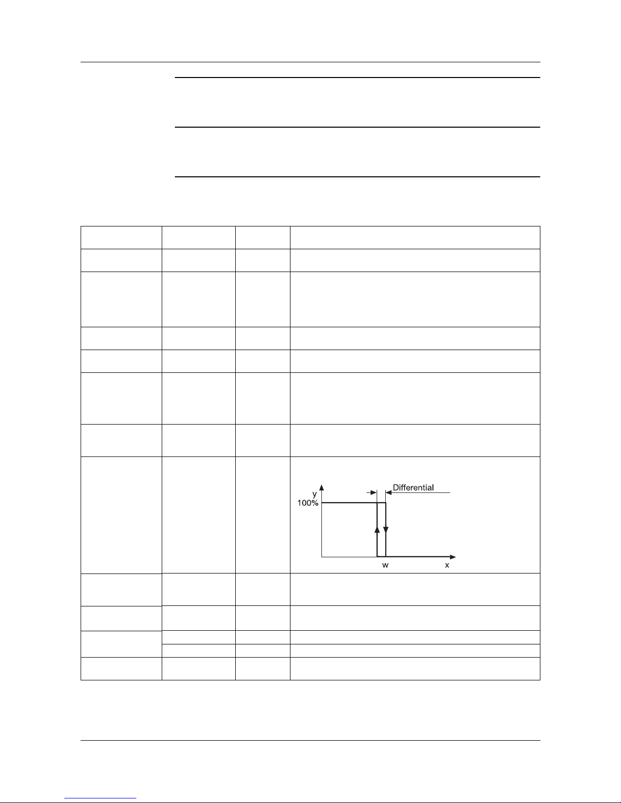
Limit comparators can have different switching functions.
Limit range AL with lk1 and lk2: 0 to 9999
Configuration
Analog inputs
Controller
Generator
Limit
comparators
Outputs
Logic functions
Math / Logic
C-level
Display
Interfaces
Device data
Recording
Timers
lk2
lk3
lk4
lk6
lk5
lk7
lk8
lk1 to lk6:
Monitoring referred to the limit
comparator setpoint.
lk7/lk8:
Monitoring referred to a fixed
value AL
w = limit comparator setpoint, AL = limit value,
x = limit comparator process value, X
Sd
= switching differential
On
On
On
On
On
On
On
On
Page 54

7 Configuration
54
Limit comparator 1 (2to16) ➔
Value/selection Value/selection
LK function no funct.
LK type 1
to
LK type 8
Limit comparator function
Limit value -1999 to 0to+9999 Limit value to be monitored
Switching
differential
0to1 to 9999 Switching differential
Action Absolute
Relative
see explanation below
Range response Relay OFF
Relay ON
Function on over/underrange
Switch-on delay 0 to 9999 sec Delays the switch-on edge by a definable time period
Switch-off delay 0 to 9999 sec Delays the switch-off edge by a definable time period
Acknowledgement none
when active
always
none:
The limit comparator is automatically reset
when active:
The limit comparator must be acknowledged;
acknowledgment is only possible in the inactive condition
always:
The limit comparator must be acknowledged;
acknowledgment is also possible in the active condition
Pulse time 0 to 9999 sec The limit comparator is automatically reset after an
adjustable time period.
LK process value (Analog selector)
Switched off
Limit comparator process value
LK setpoint (Analog selector)
Switched off
Limit comparator setpoint (only for lk1 to lk6)
Factory settings are shown bold.
H
If a limit comparator is connected to an output,
then the setting “Output signal on over/
underrange” of the output has priority.
v Chapter 7.5 “Outputs”
Page 55

55
7 Configuration
Absolute At the time of alteration, the limit comparator acts in accordance with its func-
tion.
Relative The limit comparator is in the OFF status.
An alteration of the limit value or the (limit comparator) setpoint could cause
the limit comparator to switch ON. Such a reaction will be suppressed, and
this condition is maintained until the (limit comparator) process value has
moved away from the switch-on region (gray area).
Example:
Monitoring the (controller) process value x with function lk4
Setpoint alteration w
1
w2
a) Initial condition
b) Condition at the time of the alteration.
The limit comparator remains “OFF” although the process value is within the
switch-on region.
c) Stabilized condition
The limit comparator again operates in accordance with its function.
This function also prevents a limit comparator from being triggered during the
start-up phase.
Page 56

7 Configuration
56
7.5 Outputs
Configuration of the instrument outputs are subdivided into analog outputs
(max. 6) and logic outputs (max. 12). Display and numbering of the outputs depends on the assignment of the output slots OUT 1 to 6.
Numbering of
Outputs
Configuration
Analog inputs
Controller
Generator
Limit comparators
Outputs
Logic functions
Math / Logic
C-level
Display
Interfaces
Device data
Recording
Timers
Up to 2 optional ER8 modules (additional relay or logic outputs) can
be configured through the setup program.
Caution: The ER8 modules cannot be addressed through the COM1
interface of the controller during ongoing communication between the
controller and the PC via the setup interface.
The COM1 interface of the controller is out of operation while
communication is in progress via the setup.
Slot Plug-in board with
1 analog output
Plug-in board with
1 logic output
Plug-in board with
2 logic outputs
OUT 1 Analog output 1 Logic output 1 Logic output 1+7
OUT 2 Analog output 2 Logic output 2 Logic output 2+8
OUT 3 Analog output 3 Logic output 3 Logic output 3+9
OUT 4 Analog output 4 Logic output 4 Logic output 4+10
OUT 5 Analog output 5 Logic output 5 Logic output 5+11
OUT 6 Analog output 6 Logic output 6 Logic output 6+12
Analog outputs ➔ Analog output 1 (2 to 6)➔
Value/selection Description
Function (Analog selector)
Analog inp. 1
Factory-set for analog output 2 to 6: Switched off
v See note on the analog selectors on page 39
Signal 0to10V
2to10V
0to20mA
4to20mA
Physical output signal
Signal for range 0 to 101 % Signal on going above/below range
101 = last output signal
Factory settings are shown bold.
If the output is a controller output, the controller
switches over to manual mode and produces an
output level that can be defined.
v Chapter 7.2 “Controller”
Page 57

57
7 Configuration
Zero point -1999 to 0 to +9999 A physical output signal is assigned to the value range of an
output variable.
Example:
Setpoint 1 (value range: 150 to 500 °C) is to be output via
the analog output (0 to 20 mA).
i.e.: 150to500°C = 0to20mA
Zero point: 150/End value: 500
End value -1999 to 100 to +9999
Offset -1999 to 0 to +9999 Value of the parallel shift applied to the analog output
values.
Analog outputs ➔ Analog output 1 (2 to 6)➔
Value/selection Description
Factory settings are shown bold.
Setting with controller outputs for cooling.
The following settings have to be defined for
3-state controllers:
Zero point: 0 / End value: -100
Logic outputs ➔ Logic output 1 (2 to 12)➔
Value/selection Description
Function (Binary selector)
Outp.1 contr.1
Factory-set for logic output 2 to 12: Switched off
Output mode none
Time delay
Pulse
Time delay:
The switch-on/switch-off edges can be delayed by a
definable time period.
Pulse:
A definable pulse/ pause ratio can be applied to the output.
ON time -1999 to 0 to +9999 Delay of switch-on edge or pulse time.
OFF time -1999 to 0 to +9999 Delay of switch-off edge or pause time.
Factory settings are shown bold.
Page 58

7 Configuration
58
7.6 Logic functions
Functions are assigned here to the logic signals of the logic inputs, limit
comparators and logic functions (formula).
In addition, the functions for control contacts, tolerance band signal and program end signal are defined for program controllers/generators.
In the case of the fixed-setpoint controller, the ramp end signals can have
functions assigned.
Switching
action
The functions are arranged in two groups:
Edge-triggered
functions
The logic function reacts to switch-on edges.
The following functions are edge-triggered:
• Start/stop of self-optimization
• Acknowledgement of limit comparators
• Program start/cancel
•Start timer
• Synchronize clock
• Remote alert
• Segment change
State-triggered
functions
The logic function reacts to switch-on or switch-off states.
• All remaining functions
Configuration
Analog inputs
Controller
Generator
Limit comparators
Outputs
Logic functions
Math / Logic
C-level
Display
Interfaces
Device data
Recording
Timers
Page 59

59
7 Configuration
Combined
logic functions
The functions are implemented through
the combination of up to four control
variables.
Any control variable can be selected.
The states Z1 to Z4 are assigned to the
control variables in descending order
of the control variables (see list on the
right).
Example:
The process value is to be selected via
a logic input and the state of one limit
comparator.
This results in the following assignment:
Z1 - logic input 1
Z2 - limit comparator 1
Setpoint/process value switching
0 = contact open /OFF 1 = contact closed /ON
Setpoint Process value Z2 Z1
Setpoint 1
Setpoint of system status
External setpoint
Configured controller process value
of controller channel
00
Setpoint 2 Analog input 2 0 1
Setpoint 3 Analog input 3 1 0
Setpoint 4 Analog input 4 1 1
If switching between two setpoints or process values only is required,
only one logic function has to be configured.
If more than two logic functions are configured to setpoint switching
(process value switching), only the first two (see list “Control variable
- State”) are significant.
* only for pro-
Page 60

7 Configuration
60
Program selection
0 = contact open /OFF 1 = contact closed /ON
Multifunctional
logic functions
Logic functions can cover several functions simultaneously. The desired function can be marked by a cross in the
selection list.
h Select/delete function with
h Confirm with
Program Z6 Z5 Z4 Z3 Z2 Z1
Program 1 000000
Program 2 000001
Program 3 000010
Program 4 000011
to to to to to to to
Program 64 111111
Page 61

61
7 Configuration
Logic input 1 (2 to 6) ➔
Limit comparator 1 (2 to 16) ➔
Logic 1 (2 to 16) ➔
Control contact 1 (2 to 16) ➔
Tolerance band signal➔
Program end signal➔
Ramp end signal 1 (2 to 8)➔
Timer 1 (2 to 4)
Value/selection Description
Selection of
functions
Start Tune C1
Cancel Tune C1
Manual /Auto C1
Inhibit Manual C1
to
Start Tune C8
Cancel Tune C8
Manual /Auto C8
Inhibit Manual C8
Ramp stop C1
Cancel ramp C1
Setpoint switching C1
Proc. val. switching C1
Paramset switching C1
to
Ramp stop C8
Cancel ramp C8
Setpoint switching C8
Proc. val. switching C8
Paramset switching C8
Key inhibit
Level inhibit
Text display
Display off
Display changeover
Acknowledgement LK
Prg.Auto/Man. switch
P
Inhibit program start
Program start
P
Program stop
P
Program cancel
P
Program selection
P
Fast forward
P
Segment change
P
Start self-optimization for controller 1
Cancel self-optimization for controller 1
Changeover to manual mode for controller 1
Inhibit manual mode for controller 1
to
Start self-optimization for controller 8
Cancel self-optimization for controller 8
Changeover to manual mode for controller 8
Inhibit manual mode for controller 8
Ramp stop for controller 1
Ramp OFF for controller 1
Setpoint switching for controller 1
Process value switching for controller 1
Parameter set switching for controller 1 (0=parameter set1)
to
Ramp stop for controller 8
Ramp OFF for controller 8
Setpoint switching for controller 8
Process value switching for controller 8
Parameter set switching for controller 8 (0=parameter set1
Key inhibit
Level inhibit
Tex t dis pl ay
Screen OFF
Switch over screen templates
Acknowledgement of limit comparators
Changeover between automatic and manual
Program cannot be started
Program start
Program stop
Program cancel
Program selection (see below)
Dynamic speed increase of
program sequence
Segment change
Factory settings are shown bold.
P = parameter only available for program controller/generator
Page 62

7 Configuration
62
Message types • To display the info immediately: just set info to “yes”
• To display the info after a delay:
set info to “yes” and enter delay time
• To display the alarm immediately: just set alarm to “yes”
• To display the alarm after a delay:
set alarm to “yes” and enter delay time
• To change the info to alarm after a delay time:
set info and alarm to “yes” and enter delay time.
Level inhibit • No access via “Menu” key
• The setpoint can be modified in manual operation. No access to control
contacts.
• Programs can be started and altered
Synchronize clock
Remote alert
Switch off controller 1
to
Switch off controller 4
Start timer 1
to
Start timer 4
Stop timer 1
to
Stop timer 4
Start/stop recording
function
Examples: 12:55:29 -> 12:55:00; 12:55:30 -> 12:56:00
Send e-mail (setup program)
Controller 1 is inactive
to
Controller 4 is inactive
Timer 1 is started
to
Timer 4 is started
Timer 1 is canceled
to
Timer 4 is canceled
If this signal is active, no values will be recorded.
Display text Standard text
Tex t 1
to
Tex t 1 00
No text
System texts according to function
Definable texts (only via setup program)
No entry in event list
Delay 0 to 9999sec An info or an alarm is only activated with delay
(see message types)
Message No
Ye s
Defines whether an info is produced when the logic function
is activated. The message disappears automatically when
the logic signal changes.
Alarm No
Ye s
Defines whether an alarm message is produced when the
logic function is activated.
Alarms must be acknowledged.
An entry is generated in the event list.
Logic input 1 (2 to 6) ➔
Limit comparator 1 (2 to 16) ➔
Logic 1 (2 to 16) ➔
Control contact 1 (2 to 16) ➔
Tolerance band signal➔
Program end signal➔
Ramp end signal 1 (2 to 8)➔
Timer 1 (2 to 4)
Value/selection Description
Factory settings are shown bold.
P = parameter only available for program controller/generator
Page 63

63
7 Configuration
7.7 Math and logic module
Special controller types (differential, ratio, humidity, C-level controller) or
mathematical formulae and logical combinations are configured here.
C-level control and math/logic formulae (math and logic module) are extras.
The results of the calculations can be called up, under the variables “Math X”
(math formulae) and “Logic X” (logic formulae) (X=1 to 16).
Configuration
Analog inputs
Controller
Generator
Limit comparators
Outputs
Logic functions
Math / Logic
C-level
Display
Interfaces
Device data
Recording
Timers
Math / logic 1 (2 to 16)➔
Value/selection Description
Function no funct.
Differ. (a-b)
Ratio (a/b)
Humidity (a;b)
C-level
Math formula
Logic formula
No function
Difference control (a-b)
Ratio control (a/b)
Humidity control (a;b)
C-level control
Math formula (only via setup program)
Logic formula (only via setup program)
Variable a (Analog selector)
Switched off
Variable a
Variable b (Analog selector)
Switched off
Variable b
Range start -1999 to +9999 Definition of a value range for the result of the mathematical
calculation.
If the value range is infringed, an out-of-range condition will
be signaled.
Range end -1999 to +9999
Linearization v Analog inputs
➔ Probe
Linear
The mathematical calculation can be combined with a
(customer-specific) linearization table.
Factory settings are shown bold.
Page 64

7 Configuration
64
Ratio
control
Control is always based on variable a.
The math module forms the ratio of the measurements of a and b (a/b) and
produces the setpoint for the controller. The ratio is made available as a value,
via the function “Math X”, and can be displayed.
The required ratio a/b is programmed as the setpoint (ratio setpoint) in the setpoint definition.
Humidity
control
The humidity controller receives the process value from a psychrometric
humidity probe, through the mathematical combination of wet bulb and dry
bulb temperatures.
Variable a - dry temperature
Variable b - wet temperature
Enabling the
math and logic
module
The math and logic module can be enabled through the code or the setup
program.
v Extras r Enable device options
v Operating Manual 703590.6 (on-line documentation)
Page 65

65
7 Configuration
7.8 C-level control
C-level control is used for the control of carbon in the atmosphere of a gas
coking furnace. The C-level is determined through the oxygen measurement
with a zirconium dioxide sensor and measurement of the sensor temperature.
C-level control is an extra.
Additionally, the math function has to be activated!
C-level
calculation
The calculations of the controller are based on the following:
E - e.m.f. of the zirconium dioxide sensor
T - sensor temperature in °C
P
co
- partial pressure CO in percentage of volume
C
p
- carbon level
Sequence
control
Operation using a zirconium dioxide sensor is subject to a fixed time schedule.
The sensor has to be “flushed” at regular intervals (cycle time) to ensure faultfree measurement.
During flushing and the subsequent recovery time, the controller is in manual
mode. The latest measurement is stored. The average value of the most recent
outputs is produced.
During flushing, the output variable logic 1 is “1”. The flushing procedure can
be controlled by linking it to an output.
Configuration
Analog inputs
Controller
Generator
Limit comparators
Outputs
Logic functions
Math / Logic
C-level
Display
Interfaces
Device data
Recording
Timers
E 0.0992 T -lg (P
co
1.995 0.15 Cplg CpmV/K 816.1 mV++++=
Page 66

7 Configuration
66
7.8.1 C-level control example
Analog input For C-level control, extra code C-level has to be activated and a special input
card for zirconium dioxide sensor voltage has to be installed.
Linearization h Select 0 to 10 V at the appropriate analog input
h Set to linear (not C-level)
Set display ran-geh - Set display start to 0
h - Set display end to 2000 mV
v “Display start” page 43 and “Display end” page 43
Correct assignment
Value/selection Description
Sensor voltage (Analog selector)
Switched off
Source for the voltage signal of the zirconium dioxide
sensor
Sensor
temperature
(Analog selector)
Switched off
Source for the temperature signal of the zirconium dioxide
sensor
CO measurement (Analog selector)
Switched off
Source for the measurement signal of the CO content
CO content 0to30 to 9999 If the CO content is not measured, a fixed value can be
defined here
Correction value 0to 1 to 9999 The correction value uses a reference measurement to
correct the C-level calculated by the instrument.
Cycle time 0 to 9999 min. Cycle time for sensor flushing
Flushing time 0 to 9999 min. Flushing time for sensor flushing
Recovery time 0 to 9999 min. Recovery time for sensor flushing
Factory settings are shown bold.
.
The number of the controller channel must be the same as the math/logic number and C-level number. Otherwise, the current C-level value
cannot be calculated or the controller will not switch to manual mode
during the flushing procedure.
Example: if controller 3 is used for C-level control, C-level 3 and math/
logic 3 have to be used for calculating the current C-level value. In this
case logic 3 is the signal for sensor flushing procedure.
Page 67

67
7 Configuration
7.9 Display
The time-dependent screen saving is defined here. In addition, time-out and
the sequence of the different screen templates can be defined. The
representations on the controller pictures 1 to 8 and on the collective picture
can be adapted to suit individual requirements.
Configuration
Analog inputs
Controller
Generator
Limit comparators
Outputs
Logic functions
Math / Logic
C-level
Display
Interfaces
Device data
Recording
Timers
Value/selection Description
Contrast 0to25 to 31 Contrast of color screen
Continuous
operation from
hh:mm:ss
00:00:00
Switch-on time for screen
Continuous
operation until
hh:mm:ss
00:00:00
Switch-off time for screen
Screen saving 0 to 9999 min. If no key is pressed for a specified time, the screen switches
off. The screen comes on automatically when a key is
pressed.
The function is not active during continuous operation.
0 = display is always switched on
Time-out 0to60to 9999 sec The instrument automatically returns to the display of the
screen operating loop if no key is pressed for a specified
time.
0 = no time-out
Automatic
channel
changeover
0 to 9999 sec The screen templates of the operating loop are
automatically switched over after a selectable time.
0 = switched off
Display after a
reset
last picture
Controller pic. 1
to
Controller pic. 8
Collective pic. 1
Collective pic. 2
Recording
Custom pic. 1
Custom pic. 2
Last picture before power-off is shown
Controller channel 1
to
Controller channel 8
Controller 1 to 4 as a group picture
Controller 5 to 8 as a group picture
Recording (extra code)
freely configurable screen template 1
freely configurable screen template 2
Factory settings are shown bold.
Page 68

7 Configuration
68
Operating loop
➔ Controller pic. 1
to
➔ Controller pic. 8
➔ Collective pic. 1
➔ Collective pic 2
➔ Recording
➔ Custom pic. 1
➔ Custom pic. 2
Ye s
No
The screen templates that are to appear in the screen
operating loop can be selected.
Visible as a factory setting:
- Controller pic. 1
- Recording
Value/selection Description
Factory settings are shown bold.
Controller pictures ➔ Controller picture 1 (2 to 8) ➔
Value/selection Description
Analog value 1
➔ Display
➔ Decimal place
(Analog selector)
Process value C1
XXXX.
Display for fixed-setpoint controller:
Analog value 2
➔ Display
➔ Decimal place
(Analog selector)
Setpoint C1
XXXX.
Analog value 3
➔ Display
➔ Decimal place
(Analog selector)
Output level C1
XXXX.
Logic value 1
to
Logic value 6
(Binary selector)
Output 1 C1
Program value 1
P
Segment
RemSegT PCh1
to
RemSegT PCh4
SegTime PCh1
to
SegTime PCh4
Program time
RemProgT
Display for program controller:
Program value 2
P
Segment
RemSegT PCh1
to
RemSegT PCh4
SegTime PCh1
to
SegTime PCh4
Program time
RemProgT
Factory settings are shown bold.
P = parameter only available for program controller/generator
Analog value 1
Analog value 2
Analog value 3
Logic values 1—6
Analog value 1
Analog value 2
Program value 1
Logic values 1—6
Program value 2
Page 69

69
7 Configuration
Decimal point If the value that is be displayed can no longer be represented with the
programmed decimal point, then the number of decimal places will be
automatically reduced. If, subsequently, the measured value decreases, the
number increases to the programmed value of the decimal point.
Collective picture ➔ Controller 1 (2 to 8)➔
Value/selection Description
Value column 1 (Analog selector)
Ramp end C1
Display:
Collective pic. 2: Controller 5 to 8
Decimal point
column 1
XXXX.
Value column 2 (Analog selector)
Setpoint C1
Decimal point
column 2
XXXX.
Value column 3 (Analog selector)
Output C1
Decimal point
column 3
XXXX
Factory settings are shown bold.
Column 1
Column 2
Column 3
Controller 1
Controller 2
Controller 3
Controller 4
Page 70

7 Configuration
70
7.10 Interfaces
The interface parameters for the standard RS422/485 interface (MODbus 1)
and an optional RS422/485 (MODbus 2) or PROFIBUS-DP interface have to
be configured in order to communicate with PCs, bus systems and peripheral
devices.
Configuration
Analog inputs
Controller
Generator
Limit comparators
Outputs
Logic functions
Math / Logic
C-level
Display
Interfaces
Device data
Recording
Timers
MODBUS ➔
Value/selection Description
Protocol MODBUS
MODBUS int.
Modbus integer:
All values are transferred in the integer format
Baud rate 9600
19200
38400
If two interfaces are operated at the same time, then the
baud rate 38400 for one individual interface is not
permissible.
Data format 8-1-none
8-1-odd
8-1-even
8-2-none
(data bits)-(stop bits)-(parity)
Device address 0to1 to 255 Address in data network
Minimum
response time
0 to 500 msec Minimum time that elapses between the request of a device
in the data network and the response of the controller.
Factory settings are shown bold.
PROFIBUS DP ➔
Value/selection Description
Device address 0to1 to 255 Address in data network
Factory settings are shown bold.
Interface description 703590.2
Page 71

71
7 Configuration
7.11 Device data
Basic settings such as supply frequency or temperature unit are made here.
Configuration
Analog inputs
Controller
Generator
Limit comparators
Outputs
Logic functions
Math / Logic
C-level
Display
Interfaces
Device data
Recording
Timers
Value/selection Description
Device designation (16-character text) any text
Supply frequency 50 Hz
60 Hz
Country-specific supply frequency of supply voltage
Temperature unit °C
°F
Unit for temperature values
Program
selection
Icon
Text list
A program can be selected in the program start menu,
either graphically via icons, or via a text list.
Sampling time 50 msec
150 msec
250 msec
Required basic sampling time
The sampling time possible depends on the number of
active controller channels and the utilization of the math and
logic module.
The actual sampling time is shown under “System sampling
time”.
System sampling
time
(Time display) Actual sampling time of device
Date and time
Date
Time
dd.mm.yy
hh:mm:ss
Real-time clock with calendar
d=day; m=month; y=year
h=hours; m=minutes; s=seconds
Summer time
Changeover
Start date
Start time
End date
End time
Switched off
Time definition
Automatic
dd.mm.yy
hh:mm:ss
dd.mm.yy
hh:mm:ss
Determines how to change over to summer time.
Details for the changeover through time definition
Factory settings are shown bold.
Page 72

7 Configuration
72
7.12 Recording
The recording function permits the visualization of up to four analog and three
logic signals. The signal sources are defined here.
The ring memory contains a total of 43200 measurement points. The maximum recording time depends on the storage rate that was set and the number
of measurement signals. Using the setup program, the maximum recording
time can be calculated and indicated.
A special software (accessory) is available for reading out the historical data.
Configuration
Analog inputs
Controller
Generator
Limit comparators
Outputs
Logic functions
Math / Logic
C-level
Display
Interfaces
Device data
Recording
Timers
Analog value 1 (2 to 4) ➔
Value/selection Description
Function (Analog selector)
Switched off
Recording of analog signals
Scaling start -1999 to 0 to +9999 Defines the lower and upper limit on the y-axis.
The screen template “Recording” (operating loop) can be
used to switch between the scalings of the analog values
for the graphical display of the traces.
Scaling end -1999 to 100 to +9999
Decimal place XXX.X
Unit (4-character text)
%
Any 4-character sequence can be specified.
Factory settings are shown bold.
Value/selection Description
Logic value 1 (Binary selector)
Switched off
Recording of logic signals
Logic value 2
Logic value 3
Storage rate 1to6 to 60 sec Defines the time span between the measurement points.
The ring memory will be overwritten after 43200
measurement points.
Factory settings are shown bold.
Page 73

73
7 Configuration
7.13 Timers
Timers are used for time-dependent control. The timer signal (timer 1 to 4) indicates whether the timer is active. The signal can be output via the logic outputs or processed internally.
It is possible to program up to four timers.
The timers are started and canceled through the logic functions.
Example You need to switch from setpoint 1 over to setpoint 2 for a defined time period.
Start the timer via logic input 1.
h Set the two setpoints at the operating level
h Set the timer and the timer value
Timer ➔ Timer 1 ➔ Function ➔ Signal active
h Configure the logic input
Logic functions ➔ Logic input 1 ➔ Select functions ➔
Start timer 1
h Configure the setpoint changeover
Logic functions ➔ Timer 1 ➔ Select functions ➔
Setpoint changeover C1
Configuration
Analog inputs
Controller
Generator
Limit comparators
Outputs
Logic functions
Math / Logic
C-level
Display
Interfaces
Device data
Recording
Timers
Timer 1 (2 to 4) ➔
Value/selection Description
Function no function
Signal active
Signal inactive
active, continue
inactive, continue
with the timer running: logic signal=1;
canceled after power-down
with the timer running: logic signal=0;
canceled after power-down
with the timer running: logic signal=1;
continues after power -down
with the timer running: logic signal=0;
continues after power down
Timer value hh:mm:ss
00:00:00
Time setting
Factory settings are shown bold.
Page 74

7 Configuration
74
Page 75

75
8 Optimization
8.1 Self-optimization
Oscillation
method
Self-optimization SO establishes the optimum controller parameters for PID or
PI controllers.
Depending on the controller type, the following controller parameters can be
defined:
Reset time (Tn), derivative time (Tv), proportional band (Xp), cycle time (Cy),
filter time constant (dF)
The controller selects one of two procedures (a or b), depending on the size of
the control deviation:
Step response
method
This type of optimization involves determining the control parameters through
an output step that is applied to the process. First a steady output is produced
until the process value is “steady” (constant). Afterwards, an output step (step
size), which can be defined by the user, is automatically applied to the
process. The resulting response of the process value is used to calculate the
control parameters.
Self-optimization establishes the optimum control parameters for PID or PI
controllers, in accordance with the selected control structure.
Depending on the controller type, the following control parameters can be
defined:
Reset time (Tn), derivative time (Tv), proportional band (Xp), cycle time (Cy),
filter time constant (dF)
Optimization can be started from any system status and can be repeated as
often as is required.
The controller outputs (analog, relay, solid-state), the steady output and the
step size (min. 10%) have to be defined.
Principal applications of the step response method:
- Optimization instantly after “power on”, during the start-up phase
Considerable time savings, setting: steady output = 0 %.
- The process does not readily permit oscillations (e.g. highly insulated
furnaces with small losses, long oscillation period)
- Process value must not exceed setpoint
If the output (with stabilized setpoint) is known, an overshoot can be
avoided through the following adjustment:
steady output + step size <= output in stabilized condition
a) SO in start-up phase
b) SO at setpoint
Start of SO
Start of SO
Switching
line
Page 76

8 Optimization
76
Start of self-optimization after power-on and during the start-up phase
With output type “solid-state”, the cycle time during optimization is
reduced to 8 x the sampling time.
With the “relay” output type, care has to be taken that the process
value is not influenced by the switching cycle time, since otherwise
optimization cannot be completed successfully.
Solution: Reduce the cycle time Cy, until the process value is no
longer influenced. (Manual mode can be used for the adjustment!)
Page 77

77
8 Optimization
Start of self-optimization during operation
Starting selfoptimization
Start at the operating level
h Select the controller channel in
➔ Operating level
➔
Self-optimization➔Controller number 1to8
h Start self-optimization for the selected controller channel with
➔ Status ➔ “Active”
Start from the operating loop
h Change the screen template for the required controller channel with
(press repeatedly, if necessary!)
h Press
h Press
h Start self-optimization for the required controller channel with
h Pressing resets the significance of the softkeys
The controller outputs types have to be defined for self-optimization. They also have to be enabled for the corresponding controller
channel for self-optimization to start.
v Chapter 7.2 “Controller”
In the case of a program controller, self-optimization can only be
started in the manual controller mode, during a program pause or
in the basic status (with active controller!).
EXIT
Page 78

8 Optimization
78
Canceling selfoptimization
h Switch the “Status” parameter at the operating level to “inactive” or press
again
8.2 Check of the optimization
The optimum adaptation of the controller to the process can be checked by
recording the start-up phase with the control loop closed. The diagrams below
indicate possible maladjustments and how these can be corrected.
The control response of a third-order control loop of a PID controller is shown
as an example. However, the procedure for adjusting the controller parameters
can also be applied to other control loops.
Xp too large
Xp too small
Tn, Tv too large
Tn, Tv too small
optimum
adjustment
Cy too large
Page 79

79
9 Retrofitting of modules
The following steps are necessary for retrofitting modules:
Safety notes
Identifying the
module
h Identify the module by the Sales. No. affixed to the packaging
Only qualified personnel are permitted to retrofit modules.
V
For safety reasons, care must be taken that the back panel and the
fixing screws are correctly reassembled and mounted after the
alterations.
E
The modules can be damaged by electrostatic discharge. Avoid
electrostatic charge during fitting and removal. Carry out retrofitting on a
workbench that is earthed.
Modules Code Part no. Board No.
Universal input
a
Inputa for zirconium dioxide sensor 0 to 2 V
a
The instrument is fitted from device software version 162.04.01 on with a new type of analog
input card. If analog input cards are retrofitted, it must be noted that they cannot be operated
together with the older type of card (i.e. do not mix card types).
Please note also that an update of the setup program may be required in order to carry out the
configuration through the setup program.
The device software version (version number) can be read out from the instrument in the “Device info” menu.
The nameplate can also be used to determine whether the new analog input modules have
been fitted to the instrument (see Chapter 2.3 “Nameplate”).
00489149 00483500
00483395
Outputs:
1 relay (changeover contact)
Solid-state relay 230 V/1 A
2 relays (n.o.) make
1 logic output 0/22 V
b
1 analog output
1 supply for
two-wire transmitter
b
2 logic outputs 0/14 V
b
The boards for the 0/22 V logic output and the supply for a two-wire transmitter are identical,
and are detected by the instrument and the setup program as “Logic output 0/22 V”.
1
2
3
4
5
6
7
00399782
00399783
00399784
00399785
00399786
00399785
00399788
00401153
00401185
00397011
00401267
00403601
00401267
00621622
RS422/485 interface 54 00399789 00401269
PROFIBUS-DP 64 00399790 00401264
Page 80
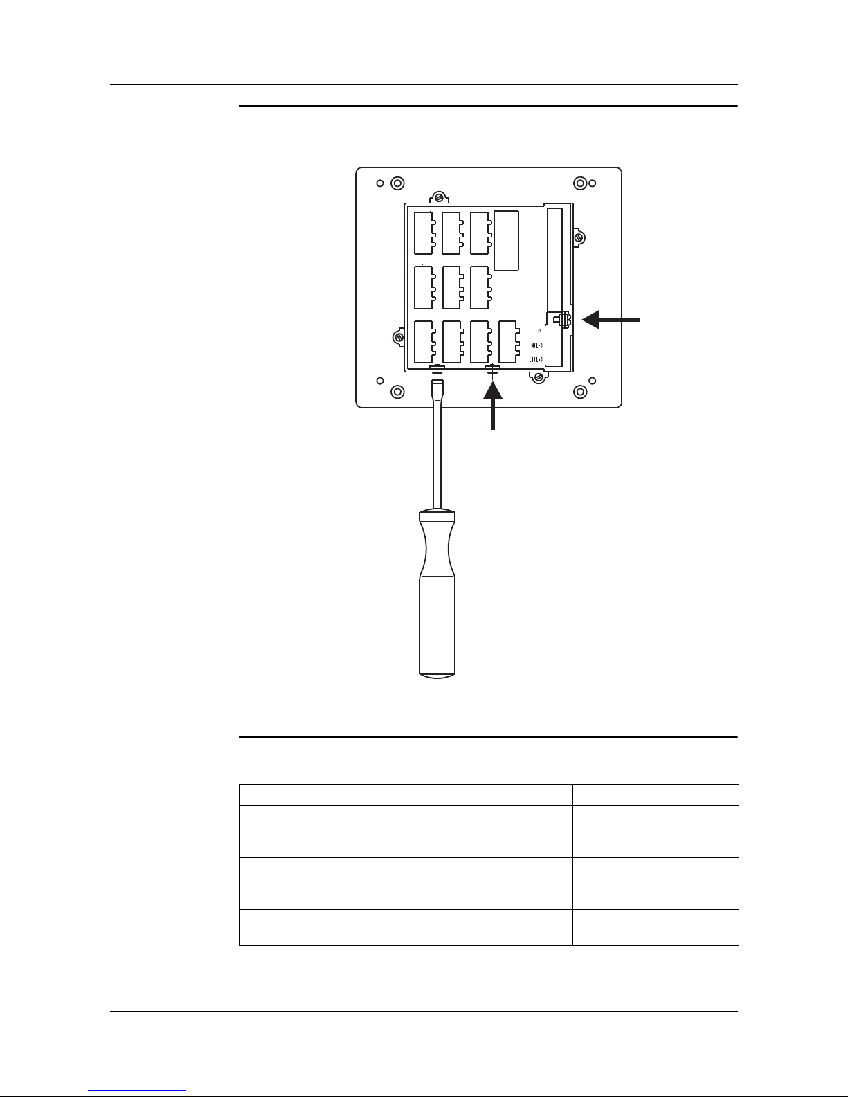
9 Retrofitting of modules
80
Removing the
back panel from
the housing
h Pull off the pluggable connector
h Loosen screws (do not remove (1) and (2)!)
h Fold back panel upwards and take it off
Slot assignment The slots for the individual modules are printed on the back panel of the
housing:
(1) (2)
(3)
OUT 1 / IN 5
OUT 4 / IN 8
IN 2
IN 1
OUT 3 / IN 7
OUT 5
OUT 2 / IN 6
OUT 6
IN 3
IN 4
COM 2
COM 1
29-32
BIN
INPUT
33-44
Slot Module Function
IN 1
to
IN 8
Universal input Analog input 1
to
Analog input 4
OUT 1
to
OUT 6
Outputs Output 1+7
a
to
Output 6+12
a
a
Number of output, if two outputs are available on the board
COM 2 RS422/485
PROFIBUS DP
Interface 2
Page 81

81
9 Retrofitting of modules
Retrofitting of
modules
h Remove dummy module or existing module by using a screwdriver, for
example
h Push module into the vacant slot until the pluggable connector snaps into
place
h Hook the back panel into the slots provided on the top edge and close it.
h Tighten the screws
Mount screws correctly with shake-proof washers, since they ensure the
protective earth (PE) function (tightening torque: 100 — 120 Ncm).
Page 82

9 Retrofitting of modules
82
Page 83

83
10 Appendix
10.1 Technical data
Thermocouple input
Input for resistance thermometer
Input for standard signals
Designation Measurement range Meas. accuracy
a
a
With 250 msec sampling time
Ambient
temperature
error
Fe-Con L
Fe-Con J
Fe-Con U
Cu-Con T
NiCr-Ni K
NiCr-Con E
NiCrSi-NiSi N
Pt10Rh-Pt S
Pt13Rh-Pt R
Pt30Rh-Pt6Rh B
W5Re-W26Re C
W3Re-W25Re D
W3Re-W26Re
EN 60584
EN 60584
EN 60584
EN 60584
EN 60584
EN 60584
EN 60584
EN 60584
-200 to +900 °C
-200 to +1200 °C
-200 to +600 °C
-200 to +400 °C
-200 to +1372 °C
-200 to +915 °C
-100 to +1300 °C
0 to 1768 °C
0 to 1768 °C
0 to 1820 °C
0 to 2320 °C
0 to 2495 °C
0 to 2400 °C
0.25 %
0.25 %
0.25 %
0.25 %
0.25 %
0.25 %
0.25 %
0.25 %
0.25 %
0.25 %
b
0.25 %
0.25 %
0.25 %
b
Within range 300 to 1820 °C
100 ppm / °C
100 ppm / °C
100 ppm / °C
100 ppm / °C
100 ppm / °C
100 ppm / °C
100 ppm / °C
100 ppm / °C
100 ppm / °C
100 ppm / °C
100 ppm / °C
100 ppm / °C
100 ppm / °C
Cold junction Pt100 internal, external, or constant
Designation Connection circuit Measurement
range
Meas. accuracy
a
a
With 250 msec sampling time
Ambient
temperature
error
Pt100 EN 60751 Two-wire/three-wire -200 to +850 °C 0.05 % 50 ppm / °C
Pt50, 500, 1000 EN 60751 Three-wire -200 to +850 °C
0.1 % 50 ppm / °C
Cu50 Three-wire -50 to +200 °C
0.1 % 50 ppm / °C
Ni100 DIN 43760 Two-wire/three-wire -60 to +250 °C
0.05 % 50 ppm / °C
KTY11-6 Three-wire -50 to +150 °C 1.0 % 50 ppm / °C
PtK9 Three-wire lithium-chloride transducer
Sensor lead resistance max. 30 per lead for 2-wire or 3-wire circuit
Meas. current 250 µA
Lead compensation Is not required for a three-wire circuit. With a two-wire circuit, the lead resistance can be
compensated in software by a correction of the process value.
Designation Measurement range Meas. accuracy
a
a
With 250 msec sampling time
Ambient
temperature error
Voltage 0 to 1 0 V
-10 to +10 V
-1 to +1 V
0to+1V
0 to 100 mV
-100 to +100 mV
Input resistance R
IN
>100 k
0.2 %
0.2 %
0.1 %
0.1 %
0.1 %
0.1 %
100 ppm / °C
100 ppm / °C
100 ppm / °C
100 ppm / °C
100 ppm / °C
100 ppm / °C
C-level 0 to 2 V
Input resistance R
IN
>7.5 M
0.1 % 100 ppm / °C
Current 4 to 20 mA, voltage drop 1V
0to20mA, voltage drop 1V
(max. current load = 50 mA)
0.1 %
0.1 %
100 ppm / °C
100 ppm / °C
Heater current AC 0 to 50 mA 1 % 100 ppm / °C
Potentiometer min. 100 , max. 4 k
Standard version
Page 84

10 Appendix
84
Logic inputs
Measurement circuit monitoring
In the event of a fault, the outputs move to a defined (configurable) status.
Outputs
Controller
Color screen
Floating contacts
Sensor Overrange /
underrange
Probe or lead short-circuit Probe or lead break
Thermocouple
•- •
Resistance thermometer
•• •
Voltage 2 to 10V
0to10V
•
•
•
-
•
-
Current 4 to 20 mA
0to20mA
•
•
•
-
•
-
• = recognized - = not recognized
Relay
contact rating
contact life
changeover contact, or 2 x make
3 A at AC 250 V resistive load
150,000 operations at rated load
(with 2 x make, the supply circuits
AC 48 V cannot be combined
on one board with SELV circuitry!)
Logic
current limiting
0/14 V
20 mA
or 0/22 V
30 mA
Solid-state relay
contact rating
protection circuitry
1 A at 230 V
varistor
Voltage
output signals
load resistance
0to10V or 2to10V
R
load
500
Current
output signals
load resistance
0to20mA or 4to20mA
R
load
450
Supply voltage for
2-wire transmitter
voltage
current
22 V
30 mA
Controller type two-state controller,
three-state controller, modulating controller, continuous controller,
continuous controller with integrated actuator driver
Controller structures P/PD/PI/PID/I
A/D converter dynamic resolution up to 16 bit
Sampling time 250 msec
50 msec, 150 msec, 250 msec (configurable)
Resolution 320 × 240 pixels
Size (screen diagonal) 5" (12.7 cm)
Ty pe TFT screen with LED backlighting
No. of colors 27 colors
Page 85

85
10 Appendix
Electrical data
Housing
Interface (COM 1)
Interface (COM 2)
Approvals/marks of conformity
Supply voltage (switchmode PSU) AC 110 to 240 V +10/-15 % 48 to 63 Hz
AC/DC 20 to 30 V 48 to 63 Hz (only for operation in SELV or PELV current circuits)
Electrical safety to EN 61010, Part 1
overvoltage category III, pollution degree 2
Power consumption max. 30 VA
Data backup flash memory
Data buffering battery (restart data/start conditions of program controller/clock time)
Electrical connection at rear, via plug-in screw terminals
conductor cross-section max. 2.5 mm
2
with core ferrules (length: 10 mm)
Electromagnetic compatibility
interference emission
interference immunity
EN 61326
Class A - only for industrial use
to industrial requirements
Housing type housing and back panel: metal
for mounting in control panels/switchgear cabinets (indoor use) to IEC 61554
Front bezel plastic to UL 94 V0, 144 mm × 130 mm
Mounting depth 170 mm
Panel cut-out 92
+0.8
×92
+0.8
mm
Ambient/storage temperature range -5to50°C/-40to+70°C
Climatic conditions rel. humidity 75 % annual mean, no condensation
Site altitude up to 2000 m above sea level
Operating position horizontal
Enclosure protection to EN 60529
front IP65/rear IP20
Weight (fully fitted) approx. 1400 g
Membrane keypad polyester film, resistant to normal washing and cleaning agents
Interface type PC interface or RS422/485
Protocol Modbus
Baud rate 9600, 19200, 38400
Device address 1 to 255
Minimum response time 0 to 500 msec
Modbus
Interface type RS422/485
Protocol Modbus
Baud rate 9600. 19200, 38400
Device address 1 to 254
Minimum response time 0 to 500 msec
Profibus
Device address 1 to 128
Mark of
conformity
Te st i ng
laboratory
Certificates /
certification numbers
Test basis valid for
c UL us Underwriters
Laboratories
E201387 UL 61010-1
UL 50 - Type 1
CAN/CSA-C22.2 No. 61010-1
703590/...
Page 86

10 Appendix
86
Page 87

87
11 Index
A
Access code 35, 37
Accessories
8
Acknowledgement
54
Action
54
Actuator time
35
Alarm
62
Alteration
of the segment time for the current segment
33
of the setpoint during the current segment
33
of the setpoint for the next segment
33
Analog input
41
Analog value
72–73
B
Basic status 32
Baud rate
70
C
Cascade controller 47
Channel changeover
automatic
67
C-level control
65
Clock time
71
Close mounting
11
CO content
66
CO measurement
66
Cold-junction temperature
constant
43
external
43
Configuration level
21
Connection diagram
15
Contact spacing
35
Continuous operation
67
Contrast
67
Control action
46
Controller
46
Controller parameters
35
Controller structure
35
Controller type
46
Correction value
66
D
Date 71
Dead band
47
Decimal place
shifting
22
Decimal point
shifting
22
Derivative time
35
Details
20
Device address
70
Device designation
71
Dimensions
11
Display
67
Display end
43
E
End value
for analog signals
57
Event list
21
External relay module
8
F
Filter 43
Fitting
12
Front panel, cleaning
12
Function
generator
49
logic function
61
ramp function
50
H
Heater current monitoring 43
History
24
Hold
29
Humidity control
64
I
Info 62
Inputs
41
Installation notes
13
Interface
70
L
Level inhibit 62
Limit comparator
53
absolute
55
relative
55
Limit comparator functions
53
Limit value
54
Linearization
42, 63
Logic functions
58
combined
59
M
Manual mode 26, 32, 46
Manual output
46
Math and logic module
63
Measurement correction
42
Menu
21
Message types
62
Method
Page 88

11 Index
88
self-optimization 48
Module
identification
79
retrofitting
79
O
OFF time 57
ON time
57
Operating level
21
Operation, overview of
19
Optimization
78
Output
56
self-optimization
48
Output level
alteration
26
Output level start
47
P
Parameter level 21, 35
Password
35, 37
Power failure, response to
51
Probe
41
Program
start
30
Program editor
27, 29
Program selection
60
Program setpoint
47
Program start
50
Protocol
70
Pulse time
54
R
Ramp slope 50
Range end
43, 63
Range output level
46
Range start
43, 63
Ratio control
64
Recalibration
44
customized
43
Recording
24, 72
Relay ON time
minimum
35
Reset time
35
Response time
minimum
70
S
Sampling time 71
Screen operating loop
20, 68
Screen saving
67
Selectors
37
Self-optimization
48, 75
Sensor temperature
66
Setpoint
alteration
25
external
47
Setpoint input
23
Setpoint limits
47
Setup program
8
Start-up
2
Steady output
48
Step response method
75
Step size
48
Switching differential
35, 54
Switch-on delay
54
Symbols
18
T
Technical data 83
Temporary alterations
33
Time input
22
Time-out
19, 67
Tolerance band
29
Type designation
7
U
User level 21
V
Value input 22
Variable a
63
Variable b
63
W
Warranty 2
Working point
35
Z
Zero point
with analog signals
57
Page 89

Page 90

Page 91

Page 92

JUMO GmbH & Co. KG JUMO Instrument Co. Ltd. JUMO Process Control, Inc.
Street address:
Moritz-Juchheim-Straße 1
36039 Fulda, Germany
Delivery address:
Mackenrodtstraße 14
36039 Fulda, Germany
Postal address:
36035 Fulda, Germany
Phone: +49 661 6003-0
Fax: +49 661 6003-607
Email: mail@jumo.net
Internet: www.jumo.net
JUMO House
Temple Bank, Riverway
Harlow, Essex, CM20 2DY, UK
Phone: +44 1279 63 55 33
Fax: +44 1279 62 50 29
Email: sales@jumo.co.uk
Internet: www.jumo.co.uk
6733 Myers Road
East Syracuse, NY 13057, USA
Phone: +1 315 437 5866
Fax: +1 315 437 5860
Email: info.us@jumo.net
Internet: www.jumousa.com
 Loading...