

Page 1
Operating Manual
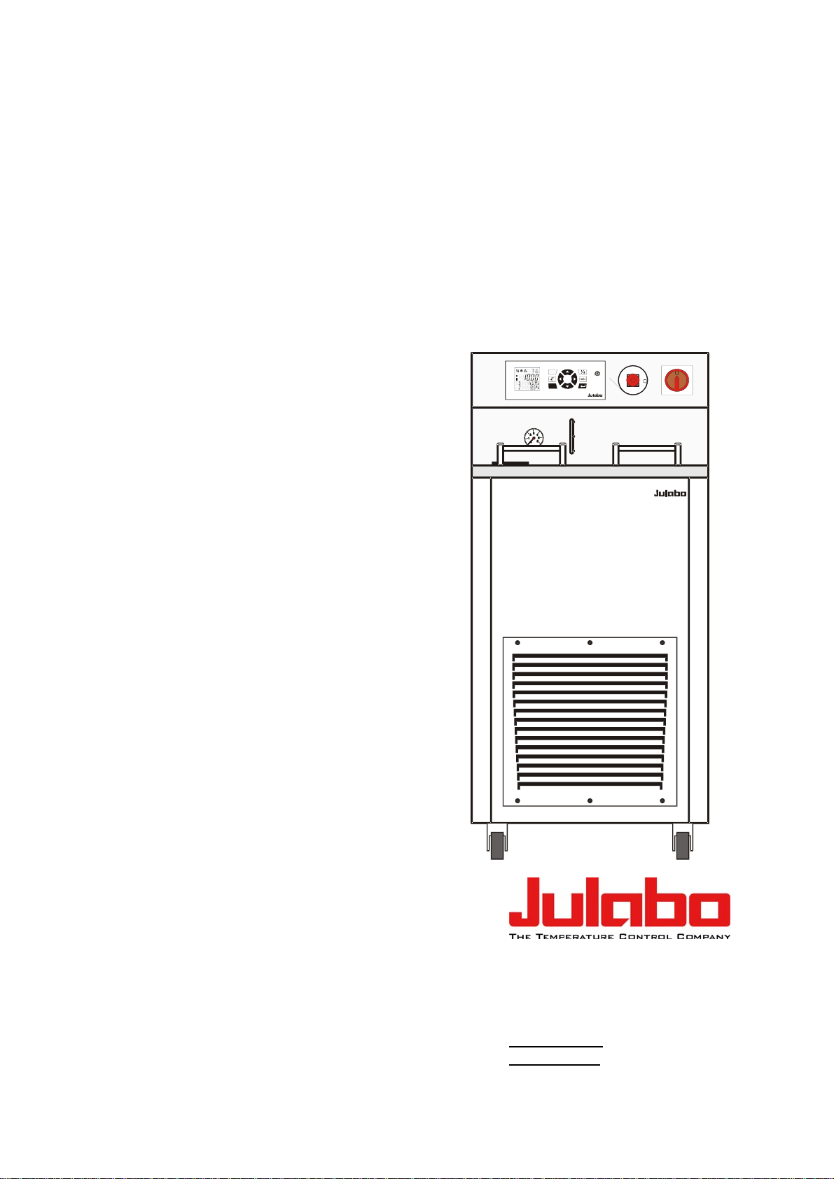
SemiChill Recirculating Coolers
Professional Series
SC 2500a
air cooled
SC 2500w
water cooled
N
E
C
G
Y
R
S
E
T
N
O
E
T
ESC
130
60
30
10
°C
P
180
220
S
U
A
T
O
N
OFF
ON
SC 2500
JULABO GmbH
77960 Seelbach / Germany
1.951.4571-V3 10/13
Tel. +49 (0) 7823 / 51-0
Fax +49 (0) 7823 / 24 91
info@julabo.de
www.julabo.de
19514571-V3.doc 08.10.2013
Page 2

Congratulations!
You have made an excellent choice.
JULABO thanks you for the trust you have placed in us.
This operating manual has been designed to help you gain an understanding of the operation and
possible applications of our circulators. For optimal utilization of all functions, we recommend that you
thoroughly study this manual prior to beginning operation.
The JULABO Quality Management System
Temperature control devices for research and industry are developed,
produced, and distributed according to the requirements of ISO 9001 and
ISO 14001. Certificate Registration No. 01 100044846
Unpacking and inspecting
Unpack the circulator and accessories and inspect them for possible transport damage. Damage
should be reported to the responsible carrier, railway, or postal authority, and a damage report should
be requested. These instructions must be followed fully for us to guarantee our full support of your
claim for protecting against loss from concealed damage. The form required for filing such a claim will
be provided by the carrier.
Printed in Germany Changes without prior notification reserved
Important: keep operating manual for future use
2
Page 3

Recirculating Cooler
TABLE OF CONTENTS
Operating manual .................................................................................................................. 5
1. Intended use ................................................................................................................... 5
1.1. Description ................................................................................................................. 5
2. Operator responsibility – Safety instructions .................................................................. 6
2.1. Disposal ..................................................................................................................... 8
2.2. EC Conformity ............................................................................................................ 9
2.3. Warranty conditions ................................................................................................. 10
2.4. Technical specifications ........................................................................................... 11
2.5. Cooling water connection ......................................................................................... 14
Operating instructions ......................................................................................................... 15
3. Operating controls and functional elements ................................................................. 15
4. Safety notes for the user .............................................................................................. 18
4.1. Explanation of safety notes ...................................................................................... 18
4.2. Explanation of other notes ....................................................................................... 18
4.3. Safety instructions .................................................................................................... 18
5. Preparations ................................................................................................................. 20
5.1. Installation ................................................................................................................ 20
5.2. Connecting the external system ............................................................................... 21
5.2.1. Tubing ................................................................................................................. 22
5.2.2. Bath fluids ............................................................................................................ 22
5.3. Filling ........................................................................................................................ 23
5.4. Draining .................................................................................................................... 24
Operating procedures ................................................................................................... 25
6.
6.1. Power connection .................................................................................................... 25
6.2. Switching on / Start - Stop ....................................................................................... 25
7.
8.
8.1. Excess temperature protection ................................................................................ 27
8.2. Over and Sub temperature warning functions.......................................................... 29
Setting the temperatures .................................................................................... 26
Safety installations, warning functions ................................................................ 27
8.1.1. Early warning system, low level protection .......................................................... 28
8.2.1. Change-over of the warning function to shutdown function ................................. 30
3
Page 4

9.
9.1. MENU PUMP - Setting the pump pressure ............................................................... 32
9.2. MENU CONTROL – Control parameters .................................................................. 33
9.3. MENU CONFIG - configuration ................................................................................. 39
9.4. MENU SERIAL - BAUDRATE, HANDSHAKE, PARITY ........................................... 45
Menu functions .................................................................................................... 31
9.2.1. CONTROL – internal / external control ................................................................ 33
9.2.2. SELFTUNING ....................................................................................................... 35
9.2.3. DYN INT - Dynamic internal ................................................................................. 36
9.2.4. Control parameters – XP, TN, TV internal ............................................................ 36
9.2.5. COSPEED - external ............................................................................................ 38
9.2.6. Control parameters – XPU, XP, TN, TV external ................................................. 39
9.3.1. SETPOINT – Keypad control or remote control ................................................... 40
9.3.2. A-START – Autostart ............................................................................................ 41
9.3.3. OFF-MODE – Pump motor on / off ....................................................................... 42
9.3.4. RESET – Factory settings .................................................................................... 42
9.3.5. ACTVAR - actuating variable ............................................................................... 43
9.3.6. TIME / DATE – setting time and date ................................................................... 44
9.5. MENU LIMITS ........................................................................................................... 46
9.6. MENU PROGRAM – Integrated programmer ........................................................... 48
9.7. MENU ADJUST – ATC Absolute Temperature Calibration ...................................... 52
9.8.
MENU ANALOG – Analog inputs/outputs ................................................................. 56
10. Troubleshooting guide / Error messages ....................................................................... 62
11. Electrical connections .................................................................................................... 64
12. Remote control .............................................................................................................. 66
12.1. Setup for remote control ........................................................................................... 66
12.2. Communication with a PC or a superordinated data system .................................... 66
12.3. List of commands ...................................................................................................... 67
12.4. Status messages ...................................................................................................... 71
12.5. Error messages ......................................................................................................... 71
13. JULABO Service – Online remote diagnosis ................................................................. 72
14. Cleaning / repairing the unit ........................................................................................... 73
4
Page 5
Recirculating Cooler
A
Operating manual
1. Intended use
JULABO recirculating coolers have been designed to control the temperature of specific fluids in a
bath tank. The units feature pump connections for temperature control of external systems (loop
circuit).
JULABO recirculating coolers are not suitable for direct temperature control of foods,
semi-luxury foods and tobacco, or pharmaceutical and medical products. Direct
temperature control means unprotected contact of the object with the bath medium (bath
fluid).
1.1. Description
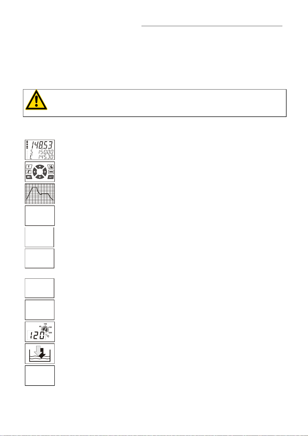
The recirculating coolers are operated via the splash-proof keypad. The
implemented microprocessor technology allows to set and to store different values
that can be indicated on the VFD COMFORT-DISPLAY. Three menu keys facilitate
adjusting setpoints, warning and safety functions and menu functions.
1x10
ICC
TCF
TC
RS232
Pt100
3
The integrated programmer allows storing and running temperature and time-
dependent processes.
“ICC - Intelligent Cascade Control“ represents the supreme solution temperature
control. ICC overs perfect temperature control with self-optimizing PID control
parameters.
The TCF - Temperature Control Features allow the user to have access to all
important temperature control parameters. This means: Full control on the control
mode and the chance to manually adjust or adapt control to the specific application.
Absolute Temperature Calibration (ATC3) provides a high temperature stability in
the bath. With the 3-point calibration an offset is adjusted at three temperatures to
ensure an accurate temperature pattern at the selected spot in the bath over the
full temperature range.
Electrical connections:
The serial interface, switchable from RS232 to RS485, allows modern process
technology without additional interface.
Connection for Pt100 external sensor for external temperature measurement and
control.
The electronic module (option) provides 3 further analog connections (alarm input,
standby input, recorder output, programmer input).
The excess temperature protection conforming to IEC 61010-2-010 is a safety
installation independent from the control circuit. This protection can be indicated
and set on the VFD COMFORT-DISPLAY.
SMART
PUMP
The early warning system for low level signals that bath fluid needs to be refilled
before the low level protection conforming to IEC 61010-2-010 causes a complete
shutdown of the main functional elements.
Intelligent pump system: The pump capacity (electronically adjustable via the motor
speed) enables to adapt to varying conditions for internal and external temperature
applications.
5
Page 6

Operator responsibility – Safety instructions
2. Operator responsibility – Safety instructions
The products of JULABO ensure safe operation when installed, operated, and maintained according to
common safety regulations. This section explains the potential dangers that may arise when operating
the circulator and also specifies the most important safety precautions to preclude these dangers as far
as possible.
The operator is responsible for the qualification of the personnel operating the units.
The personnel operating the units should be regularly instructed about the dangers involved with
their job activities as well as measures to avert these dangers.
Make sure all persons tasked with operating, installing, and maintaining the unit have read and
understand the safety information and operating instructions.
When using hazardous materials or materials that could become hazardous, the circulator may be
operated only by persons who are absolutely familiar with these materials and the circulator. These
persons must be fully aware of possible risks.
If you have any questions concerning the operation of your unit or the information in this manual,
please contact us!
Contact:
Safety instructions for the operator:
Avoid strikes to the housing, vibrations, damage to the operating-element panel (keypad, display),
and contamination.
Make sure the product is checked for proper condition regularly (depending on the conditions of
use). Regularly check (at least every 2 years) the proper condition of the mandatory, warning,
prohibition and safety labels.
Make sure that the mains power supply has low impedance to avoid any negative effects on the
instruments being operated on the same mains.
This unit is designed for operation in a controlled electromagnetic environment. This means that
transmitting devices (e.g., cellular phones) should not be used in the immediate vicinity.
JULABO GmbH
Eisenbahnstraße 45
77960 Seelbach / Germany
Tel. +49 (0) 7823 / 51-0 info@julabo.de
Fax +49 (0) 7823 / 24 91 www.julabo.de
Magnetic radiation may affect other devices with components sensitive to magnetic fields (e.g.,
monitors). We recommend maintaining a minimum distance of 1 m.
Permissible ambient temperature: max. 40 °C, min. 5 °C.
Permissible relative humidity: 50% (40 °C).
Do not store the unit in an aggressive atmosphere. Protect the unit from contamination.
Do not expose the unit to sunlight.
6
Page 7
Recirculating Cooler
Appropriate operation
Only qualified personnel is authorized to configure, install, maintain, or repair the circulator.
Persons who operate the circulator must be trained in the particular tasks by qualified personnel. The
summarized user guidance (short manual) and the specification table with information on individual
parameters are sufficient for this.
Use
The bath can be filled with flammable materials. Fire hazard!
There might be chemical dangers depending on the bath medium used.
Observe all warnings for the used materials (bath fluids) and the respective instructions (safety data
sheets).
Insufficient ventilation may result in the formation of explosive mixtures. Only use the unit in well
ventilated areas.
Only use recommended materials (bath fluids). Only use non-acid and non corroding materials.
When using hazardous materials or materials that could become hazardous, the operator must affix
the enclosed safety labels (1 + 2) to the front of the unit so they are highly visible:
1
2
or
2
Particular care and attention is necessary because of the wide operating range.
There are thermal dangers: Burn, scald, hot steam, hot parts and surfaces that can be touched.
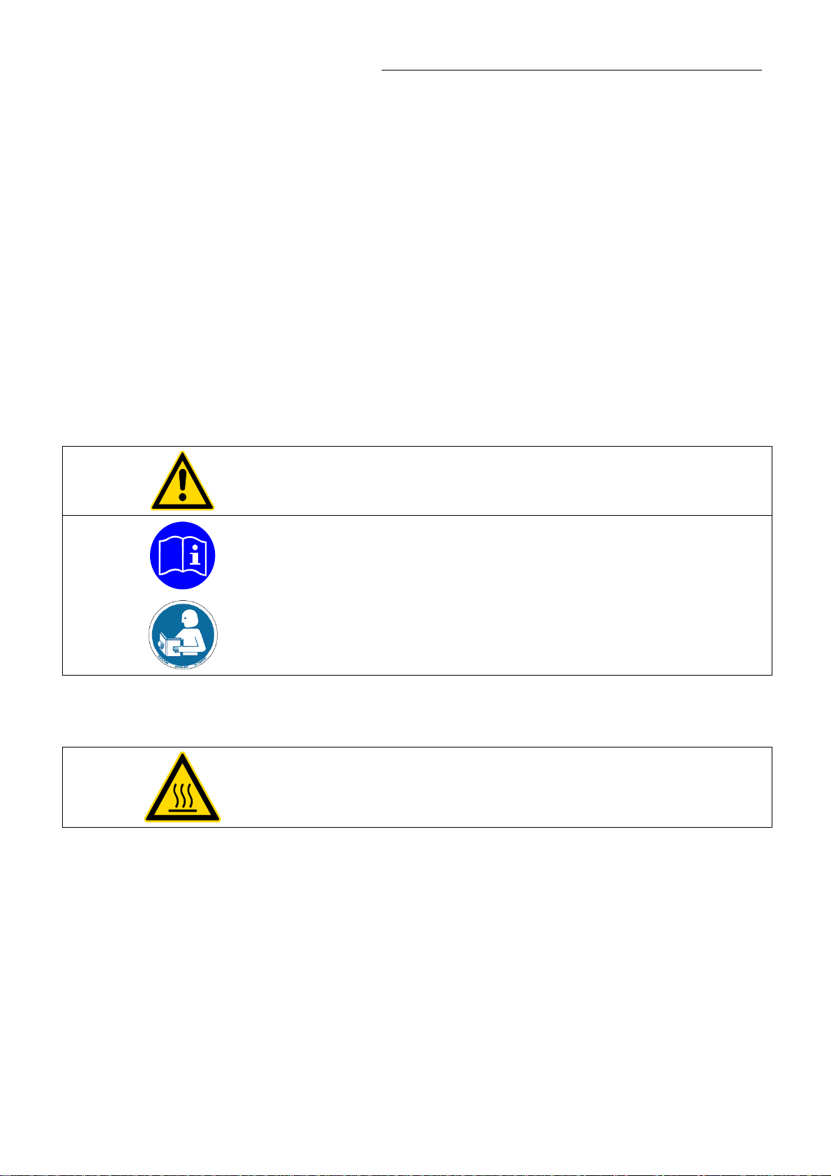
Warning label W00: Colors: yellow, black
Danger area. Attention! Observe instructions.
(operating manual, safety data sheet)
Mandatory label M018: Colors: blue, white
Carefully read the user information prior to beginning operation.
Scope: EU
Semi S1-0701 Table A1-2 #9
Carefully read the user information prior to beginning operation.
Scope: USA, NAFTA
Warning label W26: Colors: yellow, black
Hot surface warning.
(The label is put on by JULABO)
Observe the instructions in the manuals for instruments of a different make that you connect to the
circulator, particularly the corresponding safety instructions. Also observe the pin assignment of plugs
and technical specifications of the products.
7
Page 8
Operator responsibility – Safety instructions
2.1. Disposal
The recirculating cooler contains a back-up battery that supplies voltage to the memory chips when
the unit is switched off. Do not dispose of the battery with household waste!
Depending on battery regulations in your country, you may be obligated to return used or defective
batteries to collection sites.
The product may be used with oil as bath fluid. These oils fully or partially consist of mineral oil or
synthetic oil. For disposal, follow the instructions in the material safety data sheets.
This unit contains the refrigerant R404A, which at this time is not considered harmful to the ozone
layer. However, over the long operating period of the unit, disposal rules may change. Therefore, only
qualified personnel should handle the disposal.
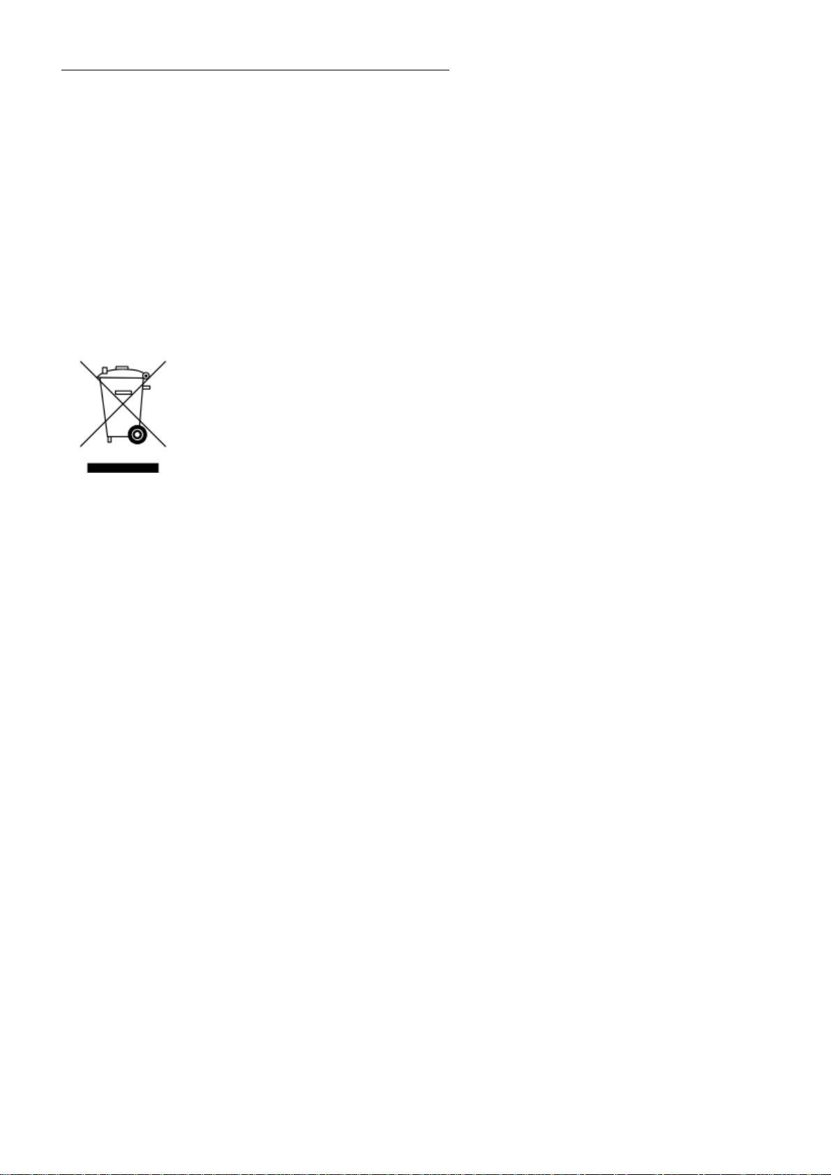
Valid in EU countries
See the current official journal of the European Union – WEEE directive.
Directive of the European Parliament and of the Council on waste electrical and
electronic equipment (WEEE).
This directive requires electrical and electronic equipment marked with a crossedout trash can to be disposed of separately in an environmentally friendly manner.
Contact an authorized waste management company in your country.
Disposal with household waste (unsorted waste) or similar collections of municipal
waste is not permitted!
8
Page 9
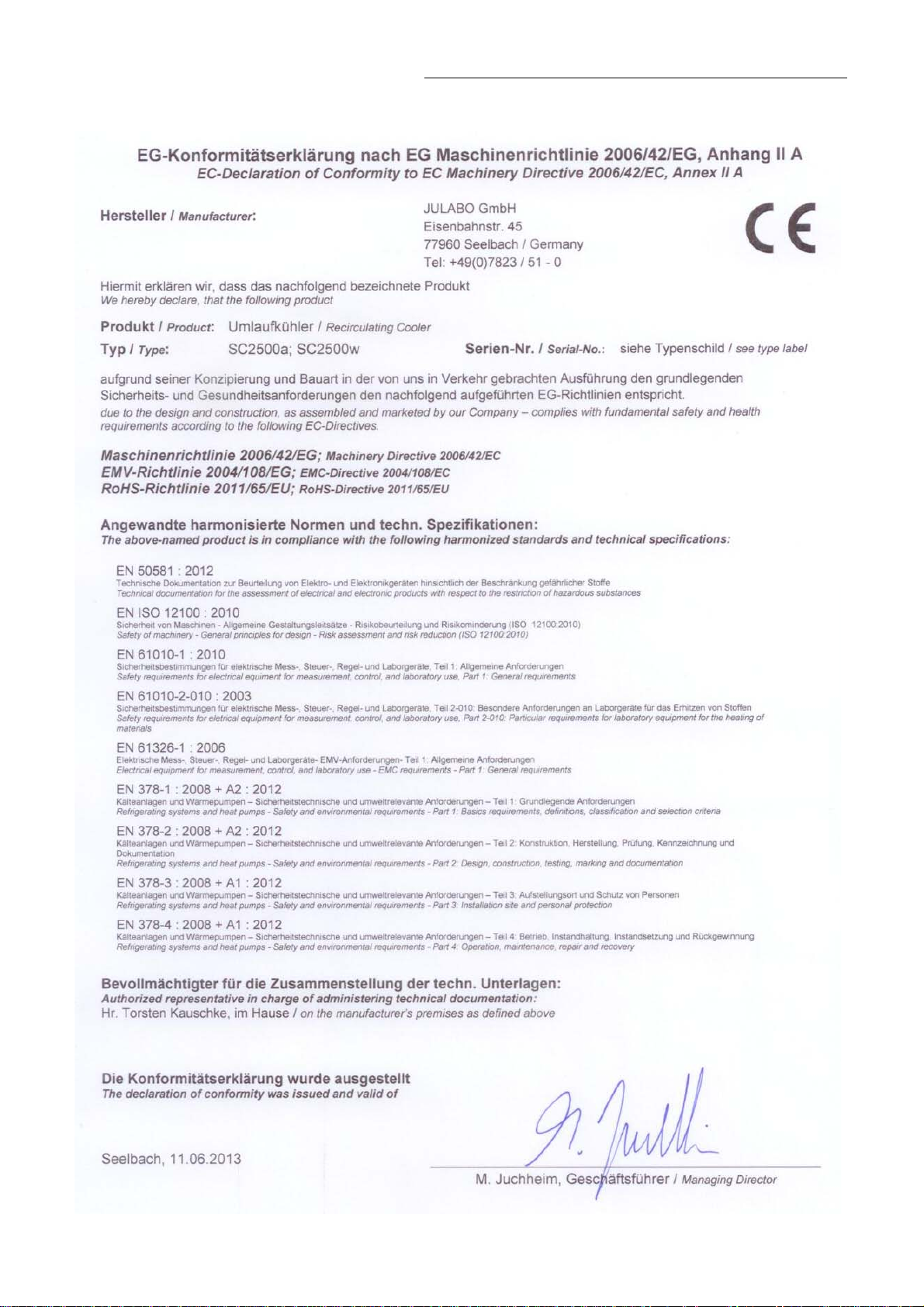
2.2. EC Conformity
Recirculating Cooler
9
Page 10

Operator responsibility – Safety instructions
2.3. Warranty conditions
JULABO GmbH warrants its products against defects in material or in workmanship, when used under
appropriate conditions and in accordance with appropriate operating instructions
for a period of ONE YEAR.
Extension of the warranty period – free of charge
With the ‘1PLUS warranty’ the user receives a free of charge extension to the warranty of up to 24
months, limited to a maximum of 10 000 working hours.
To apply for this extended warranty the user must register the unit on the JULABO web site
www.julabo.de
GmbH’s original invoice.
JULABO GmbH reserves the right to decide the validity of any warranty claim. In case of faults arising
either due to faulty materials or workmanship, parts will be repaired or replaced free of charge, or a
new replacement unit will be supplied.
Any other compensation claims are excluded from this guarantee.
, indicating the serial no. The extended warranty will apply from the date of JULABO
10
Page 11

2.4. Technical specifications
Recirculating Cooler
Professional Series
Working temperature ranges:
Standard unit °C +5 ... +35 +5 ... +35
Option Low Temp °C -20 ... +35 -20 ... +35
Option Low /HighTemp I °C -20 ... +80 -20 ... +80
Temperature stability °C 0.1 0.1
Absolute Temperature Calibration INT/EXT ±3 / ±9 ±3 / ±9
Heater wattage (at 230 V) Option H1 kW 1.0 1.0
Cooling capacity °C +20 0 -10 +20 0 -10
Medium ethanol kW 2.5 1.5 0.9
Refrigerant R404A R404A
Pump capacity P3
see table 1 page 12
Flow rate P3 l/min at 0 bar 33 33
SC 2500a SC 2500w
2.5 1.5 0.9
Pressure max. P3 bar at 0 liters 3.5 3.5
Overall dimensions (WxDxH) cm 49x62/105 49x62/105
Filling volume liters 21 ... 33 21 ... 33
Weight kg 135 122,5
Ambient temperature °C 5 ... 40 5 ... 40
Mains power connection 195-253 V/50 Hz V/ Hz 230 / 50 230 / 50
Current consumption without heater A 11 (at 230 V) 11 (at 230 V)
Current consumption 1 kW heater A 15 (at 230 V) 15 (at 230 V)
Mains power connection 195-253 V/60 Hz V/ Hz 208-230 / 60 208-230 / 60
Current consumption without heater A 11 (at 230 V) 11 (at 230 V)
Current consumption 1 kW heater A 15 (at 230 V) 15 (at 230 V)
All measurements have been carried out at: rated voltage and frequency
ambient temperature: 20 °C Technical changes without prior notification reserved.
* Pump P3- reduces cooling capacity by 0.3 kW
11
Page 12
Operator responsibility – Safety instructions
X
P
X
P
2
Professional series
Temperature selection digital
via keypad indication on VFD COMFORT-DISPLAY
remote control via personal computer indication on monitor
Temperature indication °C VFD COMFORT-DISPLAY
Resolution °C 0.1
Temperature control ICC - Intelligent Cascade Control
Electrical connections:
Computer interface RS232
External Pt100 sensor
Optional
Programmer input -100 °C to 400 °C = 0 - 10 V or 0 - 20 mA or 4 - 20 mA
Input for the signal of a flow meter or external manipulated variable
Temperature recorder outputs 0 - 10 V (0 V = -100 °C, 10 V = 400 °C)
0 - 20 mA (0 mA = -100 °C, 20 mA = 400 °C)
4 - 20 mA (4 mA = -100 °C, 20 mA = 400 °C)
Standby input for external emergency switch-off
Alarm output for external alarm signal
Table 1
Pump capacity
Bath fluid: Water, Silicone -oil
Circulating pump:
Flow rate max. Lpm at 0 bar
Pressure max. bar at 0 liter
Bath fluid: Galden
eg. Fluorinert
Pressure max. bar at 0 liter
®
®
3283
Notice:
If Galden® or Fluorinert® is used the the charge of the motor increases. Wrong
adjustment causes overheating and eventually destruction of the motor.
With the circulation pump P3 a maximum pump pressure stage >PUMP 1< may
be adjusted..
The pump type can be recognized in the order no. on the name plate.
95 xx xxx _ xx PX xx
X.XX
UMP
1
P3 P3
30 33
1.8 3.5
3.5
X.XX
UMP
12
Page 13

Safety installations according to IEC 61010-2-010:
Excess temperature protection adjustable from 0 °C ... 220 °C
Low liquid level protection float switch
Classification according to DIN 12876-1 class III
Supplementary safety installations
Early warning system for low level float switch
High temperature warning function optical + audible (in intervals)
Low temperature warning function optical + audible (in intervals)
Supervision of working sensor plausibility control
Reciprocal sensor monitoring between
working and safety sensors difference >35 °C
Alarm message optical + audible (permanent)
Warning message optical + audible (in intervals)
Recirculating Cooler
Environmental conditions according to IEC 61 010-1:
Use indoors only.
Altitude up to 2000 m - normal zero.
Ambient temperature: see Technical specifications
Humidity:
Max. relative humidity 80% for temperatures up to +31 °C,
linear decrease down to 50% relative humidity at a temperature of +40 °C
Max. mains voltage fluctuations of ±10% are permissible.
Protection class according to IEC 60 529 IP21
The unit corresponds to Class I
Overvoltage category II
Pollution degree 2
Caution:
The unit is not for use in explosive environment.
EMC requirements according to EN 61326-1
This unit is an ISM device classified in Group 1 (using high frequency for internal purposes), Class A
(industrial and commercial range).
13
Page 14
Operator responsibility – Safety instructions
2.5. Cooling water connection
Cooling water pressure (IN/OUT) max. 6 bar
Pressure difference (IN - OUT) 3.5 to 6 bar
Cooling water temperature < 20 °C
Notice: Cooling water circuit
Risk of oil leaking from the refrigeration system (compressor) of the recirculating
cooler into the cooling water in case of a fault in the cooling water circuit!
Observe the laws and regulations of the water distribution company valid in the location where
the unit is operated.
Notice:
Danger of corrosion of heat exchanger due to unsuitable quality of cooling
water.
Due to its high content of lime, hard water is not suitable for cooling and causes
scale in the heat exchanger.
Ferrous water or water containing ferrous particles will cause formation of rust
even in heat exchangers made of stainless steel.
Chlorinated water will cause pitting corrosion in heat exchangers made of
stainless steel.
Due to their corrosive characteristics, distilled water and deionized water are
unsuitable and will cause corrosion of the bath.
Due to its corrosive characteristics, sea water is not suitable.
Due to its microbiological (bacterial) components, which settle in the heat
exchanger, untreated and unpurified river water and water from cooling towers is
unsuitable.
Avoid particulate matter in cooling water.
Avoid putrid water.
Recommended quality of cooling water:
pH 7.5 to 9.0
Sulfate [SO4 2- ] < 100 ppm
Hydrocarbonate [HCO 3-]/sulfate [SO4 2-] > 1 ppm
Hardness [Ca 2+, Mg 2+]/[HCO 3-]
Alkalinity 60 ppm < [HCO 3-] < 300 ppm
Conductivity < 500 μS/cm
Chloride (Cl -) < 50 ppm
Phosphate (PO4 3-) < 2 ppm
Ammonia (NH3) < 0.5 ppm
Free chlorine < 0.5 ppm
Trivalent iron ions (Fe 3+) < 0.5 ppm
Manganese ions (Mn 2+) < 0.05 ppm
Carbon dioxide (CO2) < 10 ppm
Hydrogen sulfide (H2S) < 50 ppm
Content of oxygen < 0.1 ppm
Algae growth impermissible
Suspended solids impermissible
> 0.5 dH
14
Page 15
5
C
130
Operating instructions
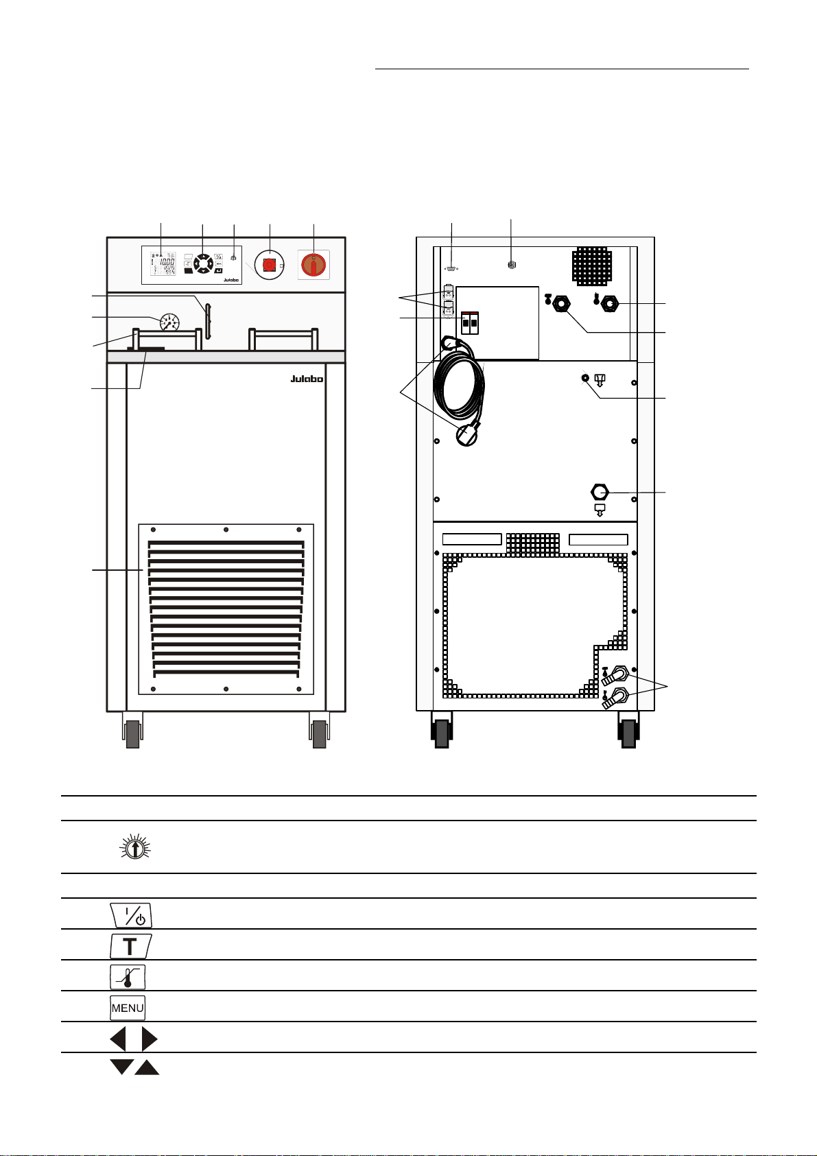
3. Operating controls and functional elements
Front view Rear view
5
T
ESC
3
4
G
R
E
N
130
E
60
180
30
220
10
S
°C
U
A
-
T
O
N
12
C
E
N
Y
S
T
O
P
ON
OFF
12
16
Recirculating Cooler
6
7
8
9
10
SC 2500
19
20
21
22
23
24
2
26
1 Mains power switch
2 Emergency stop switch
3
4
60
180
30
220
10
°
Keypad
Adjustable excess temperature protection according to IEC 61010-2-010
Start / stop key
Key for selecting the working temperature - Setpoint 1, 2, 3
Key for selecting the warning and safety values
MENU button - for selecting the menu functions
Cursor keys (left or right)
Edit keys (increase or decrease)
15
Page 16
Operating controls and functional elements
5
5.1
XXXXX
S xxxxx
FL GOOD
XXXXX
S xxxxx
R 005
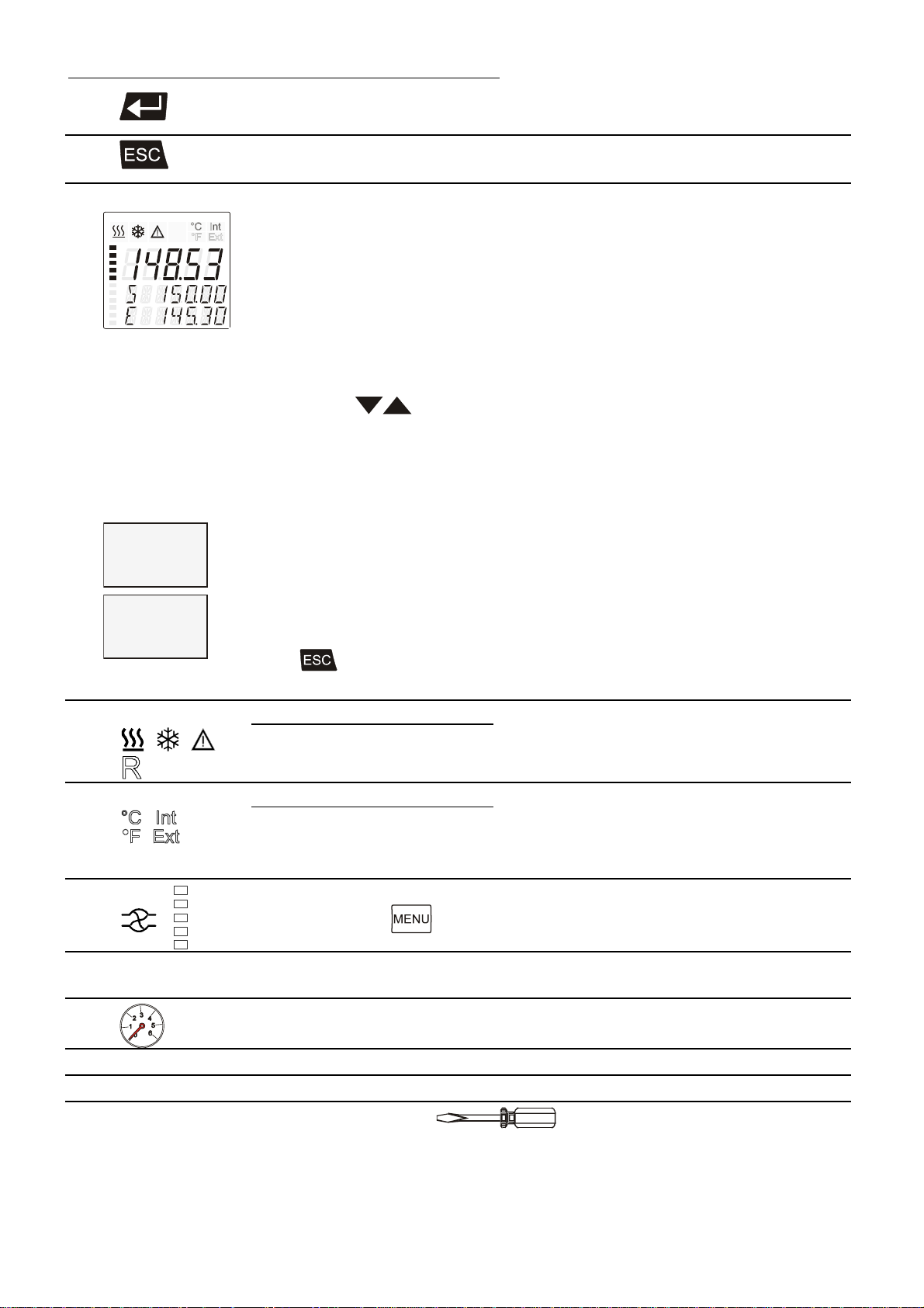
Enter key 1) Store value / parameter
2) Next lower menu level
Escape key 1. Cancel entries
2. Return to a higher menu level
VFD COMFORT-DISPLAY
Header: Control indicators see sections 2.1 and 2.2
Line 1: Actual value internal or external
The display is depending on the selected control mode in the
menu > Control < (internal or external).
Line 2: Working temp. setpoint, constantly S xxx.xx
Line 3: Actual value (E = external or I = internal)
Alternating with the display in line 1
Use the keys
functions of these keys are different with the programmer started.
PI Capacity in % - with manipulated variable set to >control<*
or
PS Capacity in % - with manipulated variable set to >SERIAL<* or
>EPROG<*
F Flow rate in liters/minute
(providing EPROG input set to >FLOWRATE<)
*see 9.3.5. ACTVAR - page 43
FL Status indication for flow >GOOD< = Pump switched on
R Resistifity measurement and actual value display in the range from
0.5 ... 5 MOhm/cm
Press
Control indicators in the header:
Heating / Cooling / Alarm /
to return to actual value (E = external or I = internal)
to indicate further values in line 3. However, the
5.2
5.3
6
7
8
9
10
Filling level indication
Handle
Filling opening
Remote control
Control indicators in the header:
Temperature indication Internal or External actual value
Temperature indication in °C (°F not possible on this unit)
Display for the adjusted pump pressure stage.
Adjustable via the
Manometer (feed pressure)
Venting grid, removable
(only air cooled recirculating cooler)
button, in the menu >PUMP<.
16
Page 17
O
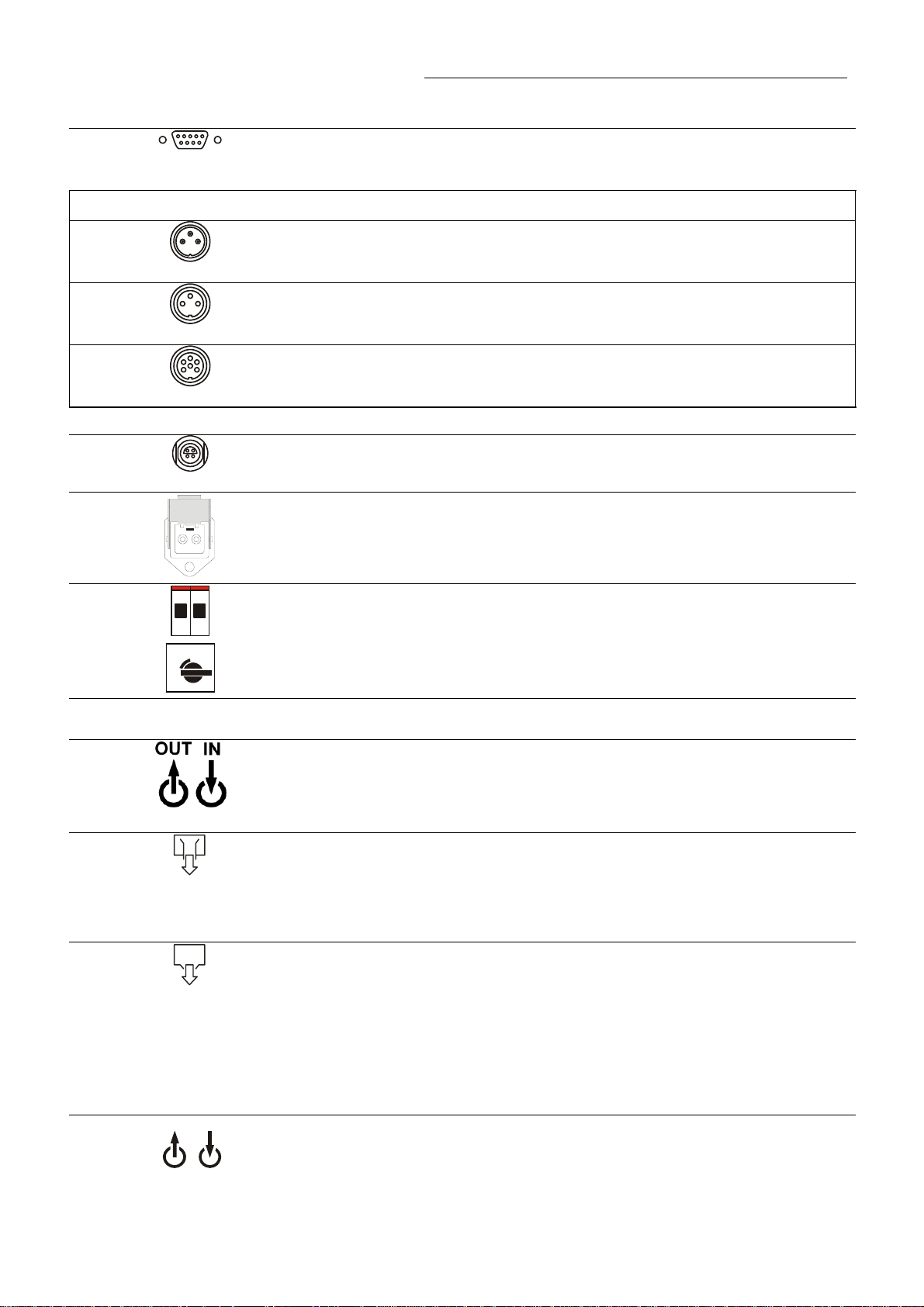
Rear view
12
Interface RS232: remote control via personal computer
RS232
Option: Electronic module
13
Alarm output (for external alarm signal)
ALARM
14
Standby input (for external emergency switch-off)
STAND-BY
15
Programmer input and temperature recorder output
REG+E-PROG
16
Socket for external measurement and control sensor
or external setpoint programming
ext Pt100
19
2 Connectors for solenoid valve. 230 V / max. 0.1 A
No control voltage in the -OFF- condition
Recirculating Cooler
20
2 Safety cutouts: Mains fuses 16 A
1
0
Motor protection circuit breaker for compressor motor
21 Mains power cable with plug
22
23
Pump connectors: 3/4” NPT male
OUT / Feed IN / Return
24
Overflow connector, M10x1 female
Order-No. 8 970 460 Barbed fitting for tubing 8 mm inner dia.
Closable when using e.g. 3M Fluorinert
25
Discharge nozzle with cap nut, Connection: ½ " male
Recommendation:
Before filling please install a drain cock at the discharge nozzle.
(not included in delivery)
®
as temperature liquid.
Order-No. 8 920 100 Drain cock, stainless steel
26
UT
Only for water cooled models: Cooling water OUTLET and INLET
IN
17
Page 18
Safety notes for the user
4. Safety notes for the user
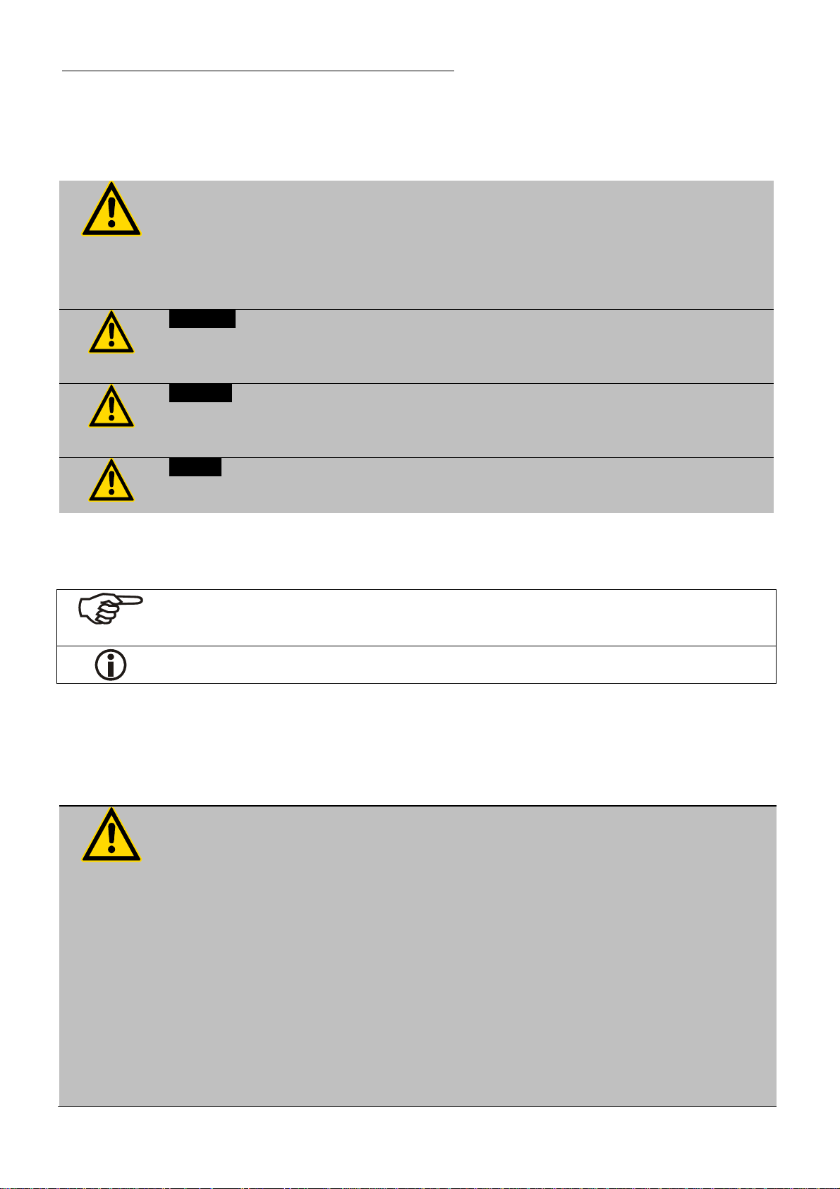
4.1. Explanation of safety notes
In addition to the safety warnings listed above, warnings are posted throughout the
manual. These warnings are designated by an exclamation mark inside an equilateral
triangle. “Warning of a dangerous situation (Attention! Please follow the
documentation).”
The danger is classified using a signal word.
Read and follow these important instructions.
Warning:
Describes a possibly highly dangerous situation. If these instructions are not followed,
serious injury and danger to life could result.
Caution:
Describes a possibly dangerous situation. If this is not avoided, slight or minor injuries
could result. A warning of possible property damage may also be contained in the text.
Notice:
Describes a possibly harmful situation. If this is not avoided, the product or anything in
its surroundings can be damaged.
4.2. Explanation of other notes
Note!
Draws attention to something special.
Important!
Indicates usage tips and other useful information.
4.3. Safety instructions
Follow the safety instructions to avoid personal injury and property damage. Also, the
valid safety instructions for workplaces must be followed.
Only connect the unit to a power socket with an earthing contact (PE – protective
earth)!
The power supply plug serves as a safe disconnecting device from the line and
must always be easily accessible.
Place the unit on an even surface on a base made of nonflammable material.
Do not stay in the area below the unit.
Make sure you read and understand all instructions and safety precautions listed in
this manual before installing or operating your unit.
Set the excess temperature safety installation at least 25 °C below the fire point of
the bath fluid.
Never operate the unit without bath fluid in the bath.
Pay attention to the thermal expansion of bath oil during heating to avoid
overflowing of the fluid.
Prevent water from entering the hot bath oil.
18
Page 19

Recirculating Cooler
Do not drain the bath fluid while it is hot!
Check the temperature of the bath fluid prior to draining (e.g., by switching the unit
on for a short moment).
Use suitable connecting tubing.
Avoid sharp bends in the tubing, and maintain a sufficient distance from
surrounding walls.
Make sure that the tubing is securely attached.
Regularly check the tubing for material defects (e.g., for cracks).
Never operate damaged or leaking units.
Always turn off the unit and disconnect the mains cable from the power source
before performing any service or maintenance procedures, or before moving the
unit.
Always turn off the unit and disconnect the mains cable from the power source
before cleaning the unit.
Always empty the bath before moving the unit.
Transport the unit with care.
Sudden jolts or drops may cause damage in the interior of the unit.
Observe all warning labels.
Never remove warning labels.
Never operate units with damaged mains power cables.
Repairs are to be carried out only by qualified service personnel.
Some parts of the bath tank and the pump connections may become extremely
hot during continuous operation. Therefore, exercise particular caution when
The following questions should help to recognize possible dangers and to reduce the
touching these parts.
Caution:
The unit may be used, for example, to control the temperature of fluids in a reactor.
We do not know what substances are contained in these vessels.
Many substances are:
inflammable, easily ignited, or explosive
hazardous to health
environmentally hazardous
i.e.: dangerous
The user alone is responsible for the handling of these substances!
risks to a minimum.
Are all tubes and electrical cables connected and layed?
Note:
sharp edges, hot surfaces in operation, moving machine parts, etc.
Do dangerous vapors or gases develop during heating?
Must the work be done in a fume hood?
What to do when a dangerous substance was spilled on or in the unit?
Before starting to work, obtain information concerning the substance and
determine the method of decontamination.
19
Page 20
Preparations
Notice:
Check the safety installations at least twice a year!
Excess temperature protection according to IEC 61010-2-010
With a screwdriver, turn back the adjustable excess temperature protection until
the shutdown point (actual temperature).
Low level protection according to IEC 61010-2-010
To check the function of the float, it can be manually lowered with a screwdriver,
for example.
5. Preparations
5.1. Installation
Place the unit in an upright position.
For better stability, apply the holding brakes on the front casters.
The place of installation should be large enough and provide
sufficient air ventilation to ensure the room does not warm up
excessively because of the heat the instrument rejects to the
environment. (Max. permissible ambient temperature: 35 °C).
For a fault (leakage) in the refrigeration system, the standard EN
378 prescribes a certain room space to be available for each kg of
refrigerant.
The refrigerant quantity is specified on the type plate.
> For 0.52 kg of refrigerant R404A, 1 m
Keep at least 20 cm of open space on the front and rear venting
grids.
Do not set up the unit in the immediate vicinity of heat sources
and do not expose to sun light
Before operating the unit after transport, wait about one hour after
installation. This will allow any oil that has accumulated laterally
during transport to flow back down, thus ensuring that the
compressor can develop its maximum capacity.
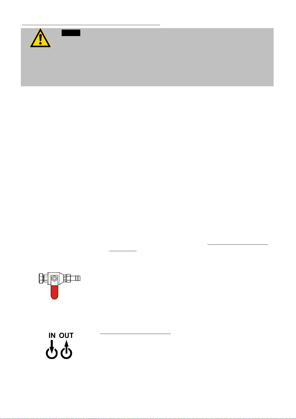
Recommendation:
Before filling please install a drain cock at the discharge nozzle. (25)
Connection: ½ " male (not included in delivery)
Order-No. 8 920 100 Drain cock, stainless steel
3
of space is required.
20
Cooling water connection (26)
Only for water cooled models
Ensure circulation of cooling water by connecting the tubing to cooling
water inlet and outlet on the rear of the recirculating cooler.
Cooling water connectors G3/4” male
Cooling water temperature <20 °C
Cooling water see page 14
:
Page 21
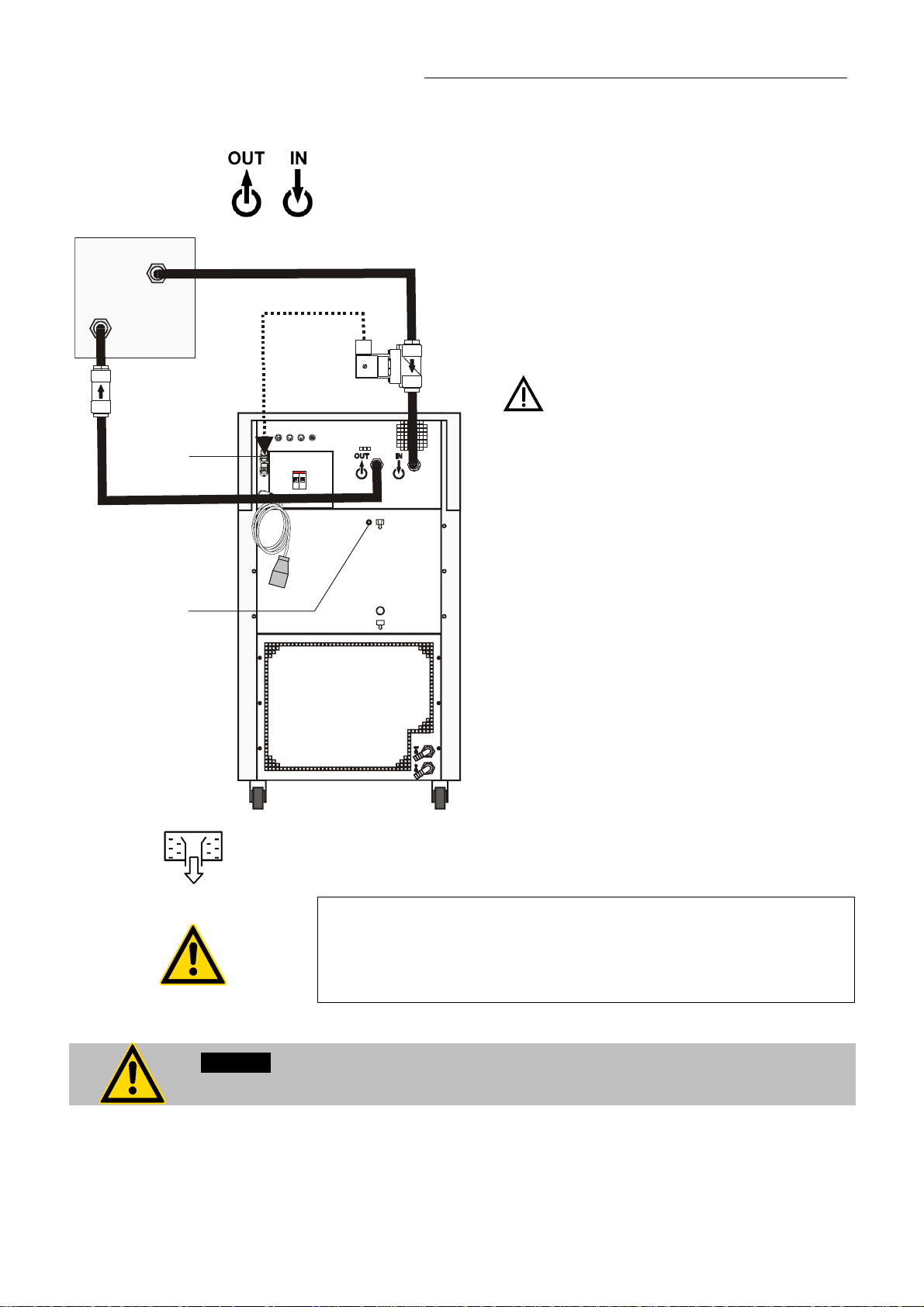
5.2. Connecting the external system
3/4" NPT male
19
Recirculating Cooler
Connect the tubing for cooling the external
system to the pump connectors (22, 23) for
feed and return on the rear of the recirculating
cooler.
In case the system to be cooled is located at
a higher level than the recirculating cooler,
take note of bath liquid flowing back when the
unit is switched off. Should the filling volume
of the bath tank not be sufficient, prevent the
liquid from flowing back by using shut-off
valves.
Flood hazard!
For this reason, solenoid valves for loop
circuit or shut-off valves can be integrated in
the loop circuit.
Connect the valve to the connector (19).
Order No. Description
8980705 Solenoid valve set 230V/50-60Hz
24
Unscrew the collar nut from the overflow connector (24).
Connect a piece of tubing to the overflow connector and drain into
a suitable vessel.
Order-No. 8 970 460 Barbed fitting for tubing 8 mm inner dia.
If easily volatile temperature liquids are used, as e.g. 3M
Fluorinert ®, the overflow should remain closed.
Attention Flood hazard!
Then the level indication (6) should get more attention.
Caution:
Securely attach all tubing to prevent slipping.
21
Page 22

Preparations
5.2.1. Tubing
Recommended tubing:
Maximum pressure
Textile-reinforced tubing > 4.5 bar
Warning: Tubing:
At high working temperatures, the tubing used for temperature control and for the
cooling water supply represents a danger source.
A damaged tubing line may allow a large amount of hot bath fluid to be pumped out
within a short time.
This may result in:
Burning of skin
Breathing difficulties due to hot atmosphere
Safety instructions
Use suitable connecting tubing.
Make sure that the tubing is securely attached.
Avoid sharp bends in the tubing and maintain a sufficient distance from
surrounding walls.
Regularly check the tubing for material defects (e.g., for cracks), at least once a
year.
Preventive maintenance: replace the tubing from time to time.
5.2.2. Bath fluids
Caution:
Carefully read the material safety data sheet of the bath fluid used, particularly with
regard to the fire point!
If a bath fluid with a fire point of 65 °C is used, only supervised operation is
possible.
Water:
The quality of water depends on local conditions.
Due to the high concentration of lime, hard water is not suitable for temperature
control because it leads to scale in the bath
Ferrous water can cause corrosion, even on stainless steel.
Chlorinated water can cause pitting corrosion.
Distilled water and deionized water are unsuitable. Their special properties
cause corrosion in the bath, even on stainless steel.
22
Page 23

Recirculating Cooler
Recommended bath fluids:
Bath fluid Temperature range
soft/decalcified water 5 °C to 80 °C
Caution:
Fire or other dangers when using bath fluids that are not recommended:
ATTENTION: The maximum permissible viscosity is 30 mm
Please contact JULABO before using other than recommended bath liquids.
JULABO assumes no liability for damage caused by the selection of an unsuitable
bath fluid.
Unsuitable bath fluids are fluids which, e.g.,
are highly viscous
(much higher than 30 mm2 x s-1 at the respective working temperature)
have a low viscosity and have creep characteristics
have corrosive characteristics or
tend to crack.
No liability for use of other bath fluids!
See website for list of recommended bath fluids.
Contact: see page 6
2
/s
5.3. Filling
Notice:
Pay attention to the thermal expansion of bath oil during heating to avoid
Liquid level
overflowing of the liquid.
Connect the tubing from the external system to the pump connectors
and check for leaks.
Check to make sure that the drain port (25) is closed.
Remove the cap from the filling opening (9).
Fill the bath tank using a funnel while monitoring the filling level (6).
Filling of the external system
Turn the mains switch (1) on
Press the key
Make sure that air can evacuate from the system..
Check the filling level (6) and keep on filling the bath liquid using the
funnel.
After having finished the filling process, the liquid level should be
below “MAX”.
Close the filling opening.
.
for filling the cooling loop for the external system.
23
Page 24

Preparations
5.4. Draining
Notice:
Do not drain the bath fluid while it is hot or cold!
Store and dispose of the used bath fluid according to the environmental
Check the temperature of the bath fluid prior to draining (by switching the unit on
for a short moment, for example).
protection laws.
Turn the mains switch (1) off.
Place a suitable vessel for accepting the used bath liquid
underneath the drain.
Unscrew the cup nut (A) from the drain port (25) and
empty the unit completely.
Close the drain port.
A
24
Page 25

6. Operating procedures
6.1. Power connection
Caution:
Only connect the unit to a power socket with an earthing contact (PE – protective
6.2. Switching on / Start - Stop
earth)!
The power supply plug serves as a safe disconnecting device from the line and
must always be easily accessible.
Never operate the unit with a damaged mains power cable.
Regularly check the mains power cables for damage.
We disclaim all liability for damage caused by incorrect line voltages!
Make sure that the line voltage and frequency match the supply voltage
specified on the type plate.
Deviations of ±10 % are permissible.
Recirculating Cooler
-OFF-
S 150.0
I 24.6
XXXXX
95xxxxx
-xxPxHx
Switching on:
Turn on the mains power switch (1).
During the self-test all segments of the VFD-Info-Display light up.
Then the software version number (example: V 4x.1x) and the order
number of the recirculating cooler appears.
(Example: [ 95 20 025 03 P3H1 ] ).
The display „OFF“ or „R OFF“ indicates the unit is ready to operate.
The recirculating cooler enters the operating mode activated before
switching the recirculating cooler off:
keypad control mode (manual operation)
or
remote control mode (operation via personal computer).
Start: Press the start/stop key
The actual bath temperature is displayed on the VFD COMFORTDISPLAY.
.
Stop: Press the start/stop key
The VFD COMFORT-DISPLAY indicates the message „OFF“.
Autostart: see chapter 9.3.2. A-START – Autostart
The Autostart function enables the start of the recirculating cooler
directly by pressing the mains switch or using a timer.
.
25
Page 26

Setting the temperatures
0
0
7. Setting the temperatures
Factory settings:
SETP 1 25 °C
SETP 2 37 °C
SETP 3 70 °C
XXXXX
SETP 3
70.
XXXXX
SETP 3
85.
Press the
3 different working temperatures are adjustable. Their values are freely
selectable within the operating temperature range.
key to call up the menu for temperature selection.
This setting may be carried out with the recirculating cooler being in the
Start or Stop condition!
Example: Setting working temperature "SETPoint 3"
1. Press the key until the desired menu window is indicated on the
VFD COMFORT-DISPLAY
Example: SETP 3 / 70.0 °C (last digit blinks)
2. Change the value to 85 °C.
Use the cursor keys
numeral you wish to change blinks.
Use the increase/decrease arrows
numeral (-, 0, 1, 2, 3, ... 9).
see example left: SETP 3 / 85.0.
to move left or right on the display until the
to change the selected
3. Press enter to store the value.
In the >Start< condition this value is immediately used for controlling the
working temperature.
The indication on the VFD COMFORT-DISPLAY is updated.
The heater control indicator blinks.
Notice: See SETMAX and SETMIN in chapter 9.5. MENU LIMITS
26
SETP 1
SETP 2
SETP 3
Example: Selecting the working temperature
1. Press the key until the desired menu item is indicated on the VFD
COMFORT-DISPLAY.
2. Press enter .
The recirculating cooler uses the new working temperature value for
temperature control.
Page 27

A
0
8. Safety installations, warning functions
Check the safety installation at least twice a year! See page 20
Settings for the excess temperature protection > SAFETMP< according to
IEC 61010-2-010 and for the high > OVERTMP< and low> SUBTMP<
SAFETMP
OVERTMP
SUBTMP
LIMITSR
8.1. Excess temperature protection
temperature warning functions are made in a menu that is called up with the
key
Menu item > LIMITSR <: „Warning“ or „Alarm“
For the two menu items > OVERTMP< and >SUBTMP< choose between a
warning message being signalled or a complete shutdown of the main
functional elements such as heater and circulating pump being effected.
.
Recirculating Cooler
XXXXX
LARM
CODE 1
XXX.X
SAFETMP
10
This safety installation is independent of the control circuit. When the
temperature of the bath fluid has reached the safety temperature, a
complete shutdown of the heater and pump is effected.
The alarm is indicated by optical and audible signals (continuous tone)
and on the VFD COMFORT-DISPLAY appears the error message
"ALARM-CODE 1".
Setting range: 20 °C ... 220 °C
1. Press the button until the menu item > SAFETMP < is
displayed.
160
80
240
40
3200
°C
°C
2. Set the new cut-out value using a screwdriver via the VFD
COMFORT-DISPLAY (Example: 100 °C)
3. Press to update the display immediately, or the unit
automatically returns to the effective display after
about 30 seconds
.
Recommendation:
Set the excess temperature protection at 5 to 10 °C above the working
temperature setpoint.
Warning:
The excess temperature protection >SafeTemp< should be set at least 25 °C below
the fire point of the bath fluid used.
There is a risk of fire in the event of a wrong setting!
We disclaim all liability for damage caused by wrong settings!
27
Page 28

Safety installations, warning functions
X
W
G
C
0
X
A
C
8.1.1. Early warning system, low level protection
This low level protection is independent of the control circuit and is
divided in two sections.
(patented)
1. Switch in stage 1 recognizes a critical fluid level
An audible warning (interval tone) sounds and a message
appears on the VFD COMFORT-DISPLAY.
.
XXXX
ARNIN
ODE 4
2. Switch in stage 2 recognizes a low fluid level
If stage 2 of the low level protection device (according to IEC
61010-2-010) is triggered, a complete shutdown of the heater
and circulating pump is effected.
A continuous alarm tone sounds and a message >ALARM<
>CODE 01< appears on the VFD COMFORT-DISPLAY.
Refill bath fluid!
.
XXXX
Important: Check the safety installations from time to time.
See page 20
Warning:
When adding bath fluid, always use the same bath fluid type that is already in the
bath.
Bath oils must not contain any water and should be pre-heated approximately to the
current bath temperature! Explosion hazard at high temperatures!
LARM
ODE 1
Turn off the unit with the mains switch, refill bath fluid and turn
the unit on again!
28
Page 29

8.2. Over and Sub temperature warning functions
Recirculating Cooler
Over temperature
Sub temperature
XXXXX
SUBTMP
-94.9
If for a sensitive temperature application task adherence to a working
temperature value > SETP < is to be supervised, then set over and sub
temperature warning values.
In the example below, the > SETP < of 85 °C is surrounded by the values
> OVERTEMP < 87 °C and > SUBTEMP < 83 °C. The electronics
immediately registers when the actual temperature attains a temperature out
of the limits and it follows a reaction according to what is set in the menu
item >LIMITSR<.
(see chapter 8.2.1. Change-over of the warning function to shutdown
function)
XXXXX
SETP
85.0
OVERTMP
87.0
SUBTMP
83,0
1. Press the button until the menu item > OVERTMP < or
>SUBTMP< is displayed.
2. Set value:
Use the cursor keys to move left or right on the display until the
numeral you wish to change blinks.
Use the increase/decrease arrows
numeral (-, 0, 1, 2, 3, ... 9).
to change the selected
3. Press enter to store the value.
The warning functions are only triggered when the actual bath
temperature, after start from the „OFF“ or „rOFF“ mode, lies within the
set limits for 3 seconds.
Recommendation:
Set the high temperature warning value > OVERTMP < at 5 °C to 10 °C
above the working temperature setpoint.
Set the low temperature warning value > SUBTMP < at 5 °C to 10 °C below
the working temperature setpoint.
29
Page 30

Safety installations, warning functions
X
W
G
C
A
X
A
C
8.2.1. Change-over of the warning function to shutdown function
Factory setting:
>WARNING<
For the two menu items > OVERTMP< and >SUBTMP< choose between a
warning message being signalled or a complete shutdown of the main
functional elements such as heater and circulating pump being effected (see
page 29).
Setting >WARNING<
An audible warning (interval tone) sounds and a meassage appears on
the VFD COMFORT-DISPLAY.
XXXXX
WARNING
CODE 03
OVERTMP SUBTMP
Setting >ALARM<
A complete shutdown of heater and circulating pump is effected.
An audible alarm (continuous tone) sounds and a message appears on
the VFD COMFORT-DISPLAY.
or
XXXXX
LARM
CODE 03
OVERTMP SUBTMP
oer
XXXX
ARNIN
ODE 04
XXXX
LARM
ODE 04
1. Press the button until the menu item >LIMITSR< is displayed.
2. Select the parameter with the keys .
(>WARNING< or >ALARM<)
3. Press enter to store the selected parameter.
30
Page 31

9. Menu functions
The term „menu functions“ refers to adjustments such as
PUMP
Electronically adjustable pump capacity page 32
Recirculating Cooler
CONTROL
CONFIG
SERIAL
LIMITS
Intelligent Cascade Control, control parameters page 33
CONTROL - internal or external control
ELFTUNING
DYNAMIC - internal
COSPEED - external
Control parameters - XP, TN, TV internal
Control parameters - XP, TN, TV, XPU external
Configurationen of the unit page 39
SET (Setpoint) – keypad control or remote control
A-START – Autostart
OFF MODE – Motor on / off
RESET – Factory settings
ACTVAR – actuating variable
TIME / DATE – Setting time and date
Adjustable interface parameters page 45
BAUDRAT, H-SHAKE, PARITY
(Baud rate, Handshake, Parity)
Limits to temperature or capacity page 46
SET MAX / MIN - Maximum and minimum setpoint
HEAT MAX - Adjusted maximum heating
COOL MAX - Adjusted maximum cooling
INTERN MAX / MIN – Limitation of the working temperature range
BAND HIGH / LOW – Band limit
PROGRAM
ADJUST
ANALOG
Indication only when
the Analog Interface
Modul is mounted.
Integrated programmer page 48
ATC - Absolute Temperature Calibration, page 52
Sensor calibration, 3-point calibration
Analog inputs/outputs page 56
F-ALARM – Function at Alarm
A-ALARM – Type of Alarm
EX-STBY - STAND-BY input
CHANNEL – Output 1, 2, 3
EPROG – External programmer input
31
Page 32

Menu functions
Menu level 1:
Example:
Menu level 1
Continue: Press
to quit the menu.
Legend:
Continue: Press
/ or
Press the button to scroll in menu level 1.
If the desired () menu item is indicated on the VFD COMFORT-
DISPLAY, press enter
Menu level 2:
Press the
display blinks.
If a value is set or a parameter selected, press enter
Each input can be cancelled with the
the next higher menu level.
The display remains visible for approx. 30 seconds
within this period,
or press the
or press
button to scroll in the selected menu item, line 3 of the
button to scroll in the menu level
to return to the next higher menu level.
to change to menu level 2.
9.1. MENU PUMP - Setting the pump pressure
to confirm.
. The cursor then returns to
. Start to set a value
Examples:
XXX.X
PUMP
2
The pressure of the circulating pump is adjustable in stages. After setting,
the VFD COMFORT-DISPLAY indicates the corresponding value.
Adjustable pump capacity stage 1 ... 3
Illuminated display:
for pump pressure
Display for the adjusted pump pressure stage.
1. Press the button until the menu item > MENU / PUMP < is
displayed.
2. Press enter to indicate the parameter.
3. Select the parameter with the keys (1 ... 3).
4. Press enter to store the selected parameter.
Continue: Press
Notice:
Pump capacity: See Table 1 page 12
or .
32
Page 33

9.2. MENU CONTROL – Control parameters
CONTROL: Press enter to switch to menu level 2
>CONTROL< (INT /
EXT
Recirculating Cooler
)
or
>SELFTUN< (ALWAYS / OFF / ONCE)
>DYNINT< (APER / NORM)
>XP INT< (0.1 ... 99.9)
>TN INT< (3 ... 9999)
>TV INT< (0 ... 999)
>CONTROL< (
>SELFTUN< (ALWAYS / OFF / ONCE)
>COSPEED< (0 ... 5)
>XP EXT< (0.1 ... 99.9)
>TN EXT< (3 ... 9999)
> TV EXT (0 ... 999)
>XPU EXT< (0.1 ... 99.9)
/ EXT)
INT
9.2.1. CONTROL – internal / external control
The recirculating cooler is conceived for internal and external
temperature control. Switching is carried out in this submenu.
Depending on what is set, only the respective set of parameters is
Factory setting:
INT
indicated.
Possible parameters:
INT internal temperature control
EXT external temperature control with external Pt100 sensor
The control type can only be adjusted in the -OFF- condition
33
Page 34

Menu functions
1. Press the button until the submenu >CONTROL< is displayed.
2. Select the parameter with the keys (INT / EXT).
3. Press enter to store the selected parameter.
Continue: Press
Notice:
Place the external sensor into the bath medium and securely fix the sensor.
IMPORTANT:
Additional measures for external temperature control.
Pt100
For external control and temperature measurement an external
Pt100 sensor must be connected to the socket (17) on the rear of the
recirculating cooler.
.Suggested adjustments for external temperature control:
BAND HIGH / LOW and INTERN MAX / MIN
see chapter > LIMITS < on page 46.
Sensor calibration of the external Pt100 sensor is carried out in the
>MENU / ADJUST<, in the submenu >ATC SEN / EXT<
(see page 52).
Accessory: Pt100 external sensor
Order No. Description Material Cable
8981003 200x6 mm Ø, stainless steel 1.5 m
8981005 200x6 mm Ø, glass 1.5 m
8981006 20x2 mm Ø, stainless steel 1.5 m
8981010 300x6 mm Ø, stainless steel 1.5 m
8981015 300x6 mm Ø, stainless steel / PTFE coated 3 m
8981013 600x6 mm Ø, stainless steel / PTFE coated 3 m
8981016 900x6 mm Ø, stainless steel / PTFE coated 3 m
8981014 1200x6 mm Ø, stainless steel / PTFE coated 3 m
8981103 Extension cable for Pt100 sensor 3.5 m
8981020 M+R in-line Pt100 sensor
Pt100 M+R
The M+R in-line Pt100 sensor is a flow sensor and can be installed loop
circuit
or
34
Page 35

9.2.2. SELFTUNING
Recirculating Cooler
XXXXX
SELFTUN
ALWAYS
Factory setting:
ONCE
Selftuning:
When performing a selftuning for the controlled system (temperature
application system), the control parameters Xp, Tn and Tv are
automatically determined and stored.
Possible parameters:
OFF - no
The control parameters ascertained during the last identification are
used for control purposes.
ONCE - single
The instrument performs a single selftuning of the controlled system
after each start with the start/stop key
command via the interface.
ALWAYS - continual
The instrument performs a selftuning of the controlled system
whenever a new setpoint is to be reached.
Use this setting only when the temperature application system
changes permanently.
selftuning
selftuning (factory setting)
or after receiving a start
selftuning
1. Press the button until the submenu > SELFTUN < is displayed.
2. Select the parameter with the keys .
(ALWAYS / OFF / ONCE)
3. Press enter to store the selected parameter.
Continue: Press
or
35
Page 36

Menu functions
A
A
9.2.3. DYN INT - Dynamic internal
This parameter affects the temperature pattern only in
case of
internal control.
Factory setting: APER (aperiodic)
°C
°C
NORM
temp. stability
PER
Setpoint
NORM
temp. stability
PER
temperature ramp
1. Press the button until the submenu > DYN INT < is displayed.
Possible parameters:
NORM Allows for reaching the setpoint faster, but
overshooting of up to 5 % is possible.
APER Target temperature is attained without
overshooting.
With both adjustments an adequate temperature
stability is reached after approximately the same time.
t
t
2. Select the parameter with the keys .
(NORM / APER)
3. Press enter to store the selected parameter.
Continue: Press
9.2.4. Control parameters – XP, TN, TV internal
Setting range:0.1 ... 99.9
Setting range:1 ...9999
The control parameters preset in factory are in most cases adequate for
achieving an optimum temperature pattern for the samples requiring
temperature application.
Each parameter may be manually set via the keypad if necessary, to
allow optimum control performance.
Proportional range >Xp<
The proportional range is the range below the selected temperature value
in which the control circuit reduces the heating power from 100 % to 0 %.
Resetting time >Tn< (Integral component)
Compensation of the remaining control deviation due to proportional
regulation. An insufficient resetting time may cause instabilities to occur.
Excessive resetting time will unnecessarily prolong compensation of the
control difference.
or
36
Page 37

Setting range: 0 ... 999
Recirculating Cooler
Lead time >Tv< (Differential component)
The differential component reduces the control settling time. An
insufficient lead time will prolong the time required to compensate for
disturbance effects and cause high overshooting during run-up. An
excessive lead time could cause instabilities (oscillations) to occur.
1. Press the button until the desired submenu is displayed -
XP INT, TN INT, TV INT.
2. Set value:
Use the cursor keys
the numeral you wish to change blinks.
Use the increase/decrease arrows
numeral (-, 0, 1, 2, 3, ... 9).
to move left or right on the display until
3. Press enter to store the value.
Continue: Press
Optimization instructions for the PID control parameters:
optimum setting
°C
/ or
The heat-up curve reveals inappropriate control
settings.
to change the selected
t
Inappropriate settings may produce the following heat-up curves:
Xp too low
°C
°C
t
Xp too high or Tv too high
t
°C
Tv/Tn too high or Xp too high
°C
Tv/Tn too low
t
t
37
Page 38

Menu functions
9.2.5. COSPEED - external
This parameter affects the temperature pattern only in case of
control.
Possible parameters:
1. Press the button until the submenu > COSPEED < is
displayed.
2. Set value:
Use the cursor keys
the numeral you wish to change blinks.
Use the increase/decrease arrows
numeral (-, 0, 1, 2, 3, ... 9).
0.0 ... 5.0
to move left or right on the display until
to change the selected
external
3. Press enter to store the value.
Continue: Press
During selftuning, the control parameters Xp, Tn and Tv of a controlled
system are automatically determined and stored. Depending on the
controlled system, time for tuning can be unequally longer. This
controller layout allows protection of sensitive objects requiring
temperature application.
/ or
°C
Int. temperature
Ext. temperature
5
3
0
Setpoint
As soon as a co-speed factor is set, it is
considered for calculating the control
parameters. As shown in the diagram,
tuning times become shorter the higher the
co-speed factor is, but overshooting can
happen in the internal system.
t
38
Page 39

9.2.6. Control parameters – XPU, XP, TN, TV external
Recirculating Cooler
Setting range: 0.1 ... 99.9
Setting range: 1 ...9999
Setting range: 0 ... 999
Setting range: 0.1 ... 99.9
The control parameters preset in factory are in most cases adequate for
achieving an optimum temperature pattern for the samples requiring
temperature application.
Each parameter may be manually set via the keypad if necessary, to
allow optimum control performance.
1. Press the button until the desired submenu is displayed -
XP EXT, TN EXT, TV EXT, XPU EXT.
2. Set value:
Use the cursor keys to move left or right on the display
until the numeral you wish to change blinks.
Use the increase/decrease arrows to change the
selected numeral (-, 0, 1, 2, 3, ... 9).
3. Press enter to store the value.
Continue: Press
Proportional range >Xpu<
The proportional range Xpu of the cascaded controller is only needed for
external control.
/ or
9.3. MENU CONFIG - configuration
CONFIG: Press enter to switch to menu level 2
Keypad control or remote control
Autostart on / off
Motor on / off
ACTuating VARiable
EPROG* Indication only when electronic module is mounted.
>SETP< (KEY / SERIAL / PT100 / EPROG*)
>A-START< (OFF / ON)
>OFFMODE< (PMP OFF / PMP ON)
>RESET< ( NO / YES ) Factory settings
>ACTVAR< (CONTROL / SERIAL / EPROG* )
>TIME< (hh : mm ) Setting time
>DATE< (TT/MM.JJ ) Setting date
39
Page 40

Menu functions
X
X
X
X
X
X
X
9.3.1. SETPOINT – Keypad control or remote control
The recirculating cooler provides four possibilities for setpoint setting.
1. Press the button until the submenu > SETP < is displayed.
Factory setting: KEY
The selected mode is
indicated on the VFD
COMFORT-DISPLAY
-OFF-
S XX.X
I XX.X
KEY
-OFF-
S XX.X
SERIAL
-OFF-
ST XX.X
I XX.X
PT100
-OFF-
SP XX.X
I XX.X
EPROG
2. Select the parameter with the keys
(KEY / SERIAL / PT100 / EPROG)
3. Press enter to store the selected parameter.
Continue: Press
KEY – Setpoint setting with the keys and
or the integrated programmer.
SERIAL - Setpoint setting via the serial RS232 interface through a PC
or superordinated data system.
Important:
Connect the recirculating cooler to a PC using an interface cable.
Check the interface parameters of both interfaces (on recirculating
cooler and PC) and make sure they match.
(see chapter 12.1. Setup for remote control page 66)
PT100 - Setpoint setting via the analog socket „ext. Pt100“ using an
external temperature sensor or an appropriate voltage/current
source.
EPROG - Can only be adjusted when an electronic module with analog
connections is used (option).
Setpoint setting via the analog interface REG+E-PROG connection
with an external voltage or current source or a programmer.
Important:
Connect the external voltage or current source or a programmer to
the circulator via the socket REG+E-PROG (see page 59).
In the menu >MENU ANALOG< set the parameter >EPROG< and
the input variables (see page 60).
The E-Prog input can only be used either under menu item > SETP
< or under menu item > ACTVAR <
(see page 43).
/ or
40
Page 41

A
9.3.2. A-START – Autostart
Recirculating Cooler
XXXXX
-START
OFF
Factory setting: OFF
Warning:
For supervised or unsupervised operation with the AUTOSTART function, avoid any
hazardous situation to persons or property.
The instrument does no longer conform to N.A.M.U.R. recommendations.
The AUTOSTART function (automatic start mode) is allowing the start of
the instrument directly by pressing the mains power switch or using a
timer.
1. Press the button until the submenu > A-START < is displayed.
2. Select the parameter with the keys (OFF / ON).
3. Press enter to store the selected parameter.
Continue: Press
Possible parameters:
ON - AUTOSTART on
OFF - AUTOSTART off
Note:
The temperature system has been configured and supplied by JULABO
according to N.A.M.U.R. recommendations. This means for the start
mode, that the unit must enter a safe operating state after a power failure
(non-automatic start mode). This safe operating state is indicated by
OFF, resp. R OFF on the VFD COMFORT-DISPLAY. A complete
shutdown of the main functional elements such as heater and circulating
pump is effected simultaneously.
The values set on the recirculating cooler remain stored, and the unit is
returned to operation by pressing the start/stop key (in manual control
mode).
In remote control mode, the values need to be resent by the PC via the
interface.
Should such a safety standard not be required, the AUTOSTART
function (automatic start mode) may be activated, thus allowing the start
of the instrument directly by pressing the mains power switch or using a
timer.
The AUTOSTART function can only be used, if setpoint setting is carried
out via > KEY <, > EPROG < or >PT100<.
/ or
The safety and warning functions of the instrument should always be used to their
fullest capacity.
41
Page 42

Menu functions
9.3.3. OFF-MODE – Pump motor on / off
XXXXX
OFFMODE
PMP OFF
Factory setting:
PMP OFF
Normally the circulating pump is switched via the start/stop signal.
However, if circulation should be maintained also for the -OFF- condition,
the parameter >
Possible parameters:
PMP ON Pump motor on
PMP OFF Pump motor off
PMP ON< needs to be set.
1. Press the button until the submenu > OFFMOD < is displayed.
2. Select the parameter with the keys .
(PMP ON / PMP OFF)
3. Press enter to store the selected parameter.
Continue: Press
/ or
In case of an alarm state, a shutdown of the pump motor is still
effected.
9.3.4. RESET – Factory settings
Use this to reset all values to factory setting (except date and time).
A RESET can only be carried out in the -OFF- condition.
Factory setting:
NO
Possible parameters:
NO / YES
1. Press the button until the submenu > RESET < is displayed.
2. Select the parameter with the keys (NO / YES).
3. Press enter to store the selected parameter.
As long as the message -RUN- appears all parameters a reset to
factory settings.
42
Page 43

A
A
A
A
9.3.5. ACTVAR - actuating variable
Recirculating Cooler
XXXXX
CTVAR
CONTROL
Factory setting:
CONTROL
XXXXX
CTVAR
SERIAL
XXXXX
CTVAR
EPROG
The variable
the heater or cooling machine of the recirculating cooler is controlled.
Heat or cold is applied to the bath according to this variable. If this
happens with the control electronics of the recirculating cooler, called
> CONTROL < in this particular case, the bath temperature is exactly
heated and maintained constant at the adjusted setpoint.
(ACTuating VARiable) corresponds to the extent to which
Programming of variables for the parameters > SERIAL < or >
EPROG < is only accepted, if the unit is in Start mode.
1. Press the button until the submenu > ACTVAR < is displayed.
2. Select the parameter with the keys
(CONTROL / SERIAL / EPROG )
3. Press enter to store the selected parameter
Continue: Press
Possible parameters:
CONTROL – The internal control electronics of the recirculating cooler
controls the heater and cooling machine. Self-tuning is possible.
SERIAL – The heater or cooling machine receives the control signal via
the serial interface. Self-tuning is not possible.
EPROG - The heater or cooling machine receives the control signal via
the E-Prog input. Self-tuning is not possible.
Important:
Under >MENU ANALOG< set the input variable to
>EPROG x / ACTVAR< (see page 60).
XXXXX
EPROG U
CTVAR
/ or
Example: EPROG U / ACTVAR
Note:
The E-Prog input can only be used either under menu item
SETP < (page 40) or under menu item > ACTVAR <.
>
43
Page 44

Menu functions
E
E
Warning:
The working temperature range of the recirculating cooler is determined during
configuration. If set to >CONTROL<, this range cannot be exceeded.
If set to > SERIAL < and > EPROG <, heat or cold is applied to the bath without
control. The permissible maximum temperature can be exceeded. The user has to
take adequate precautions for temperature control.
Materials, such as gaskets or insulations for example, may be damaged or
destroyed, if the permissible maximum temperature is exceeded.
The safety and warning functions of the instrument should always be used to their
fullest capacity.
8. Safety installations, warning functions page 27
9.3.6. TIME / DATE – setting time and date
XXXXX
The integrated clock allows starting a profile at any date and time. The
clock is preset in the factory.
TIM
16h4317
hh mm
XXXXX
DAT
10/1203
TT/MM.JJ
1. Press the button until the submenu > TIME < or > DATE < is
displayed.
2. Setting time / date:
Use the cursor keys
the numeral you wish to change blinks.
Use the increase/decrease arrows
numeral (-, 0, 1, 2, 3, ... 9).
3. Press enter to store the value.
Continue: Press
Clock: Only hours and minutes are set.
Settings are checked for plausibility.
to move left or right on the display until
to change the selected
/ or
44
Page 45

9.4. MENU SERIAL - BAUDRATE, HANDSHAKE, PARITY
XXXXX
MENU
SERIAL
Factory settings:
4800 Bauds
even
hardware handshake
For communication between recirculating cooler and a PC or a
superordinated process system the interface parameters of bath units
must be identical.
SERIAL: Press enter to switch to menu level 2
>BAUDRAT<
>PARITY<
>H-SHAKE<
Recirculating Cooler
1. Press the button until the desired menu item is displayed.
2. Select the parameter with the keys .
3. Press enter to store the selected parameter.
Continue: Press
Adjustable interface parameters
BAUDRATE 4800 bauds
9600 bauds
PARITY no
odd
even
/ or
HANDSHAKE
SOFT = software handshake
HARD = hardware handshake
Data bits = 7; Stop bits = 1
45
Page 46

Menu functions
M
S
X
0
9
9.5. MENU LIMITS
XXXXX
ENU
LIMIT
LIMITS: Press enter to switch to menu level 2
>SET MAX<
>SET MIN<
>HEATMAX<
>COOLMAX<
>INT MAX<
>INT MIN<
>BAND H<
>BAND L<
In case of external control
these menu items are
additionally indicated.
1. Press the button until the desired submenu is displayed
2. Set value:
Use the cursor keys
the numeral you wish to change blinks.
Use the increase/decrease arrows
numeral (-, 0, 1, 2, 3, ... 9).
to move left or right on the display until
to change the selected
Factory settings
XXXXX
SET MA
300.0
XXXXX
SET MIN
-94.9
3. Press enter to store the value.
Continue: Press
SETPOINT MAX / MIN - Maximum and minimum setpoint
Restriction for the adjustable temperature range.
The limitation of the operating temperature range effects the temperature
setting under the menu called up with the
It is possible to adjust only working temperatures that lie within the limit
range set here.
Existing settings for SETP 1, 2, 3 and also for >OVERTEMP< and
>SUBTEMP< (see page 29) are automatically defered within the limit
range.
Setting range::
-94.99 °C ... +300.0 °C
/ or
key.
46
Page 47

Recirculating Cooler
X
0
9
Factory settings
Factory settings
XXXXX
INT MA
300.0
XXXXX
INT MIN
-94.9
SAFETMP <
>
Adjusted maximum heating / cooling.
Heating and cooling powers of the recirculating cooler are adjustable.
100 % corresponds to the values in the technical specifications of the
equipment.
Setting range:
HEAT MAX – 0 to 100 % in steps of 1 %
COOLING MAX – 0 to 100 % in steps of 1 %
INTERNAL MAX / MIN Limit setting
Setting range: -94.9 °C ... +300.0 °C
The limits INT MAX and INT MIN are only valid for external control. INT
MAX and INT MIN are used to limit the expected internal bath
temperatures to any upper and lower values. The temperature controller
cannot exceed these limits even if it would be required for reaching the
temperature in the external system. Consequently the external setpoint
may thus not be reached.
Sense of a limit setting:
Protects the bath fluid from overheating.
Prevents an undesired alarm shutdown by the excess temperature
protection - >
INTMAX:< to a value at least 5 °C below the >SAFETEMP:<
Set >
value.
ALARM CODE 14<.
Protects the pump motor from high viscosity of the bath fluid at low
temperatures.
For recirculating coolers: Freezing protection when using water as
bath fluid.
Factory settings:
BAND HIGH / LOW - Band limit
For the heat-up and cool-down phases different settings to conform to
the requirements of the particular application are possible.
Setting range:
Using
temperatures in the internal bath and the external system can be limited
to any maximum value for the heat-up or the cool-down phase.
During the heat-up phase the difference value always adds to the actual
external temperature. During the cool-down phase, the difference value
is subtracted.
BAND HIGH and BAND LOW, the difference between the
0 ... 200 °C
47
Page 48

Menu functions
2
M
00
150
°C
Internal bath
external system
Sense of a band limit:
Ensures gentle heating for the
objects requiring temperature
application.
Protects glass reactors, for
100
75
50
25
BAND HIGH
10 20 30 40 50 60 10 20 30 40 50 60 10
BAND LOW
[min]
t
example, from thermal shock.
The
superordinated to this band limit.
9.6. MENU PROGRAM – Integrated programmer
XXXXX
ENU
PROGRAM
1 Profil
10 Sections (STEP)
99 Repetitions
PROGRAM: Press enter to switch to menu level 2
>PS STEP< Program start at section ....
> PS RUNS < Number of profile repetitions 1 ... 99
> PS GO < Start type (NOW/TIME)
> P TIME < Start time (hh:mm)
>P DATE< Start date (TT/MM.JJ)
INTMAX: and INTMIN: values are
(Standby or last setpoint)
The integrated programmer allows any desired temperature program
sequences to be realized. Such a temperature sequence is called profile. A
profile consists of individual sections defined by duration (t:) and target
temperature. Target temperature is the setpoint (T:), that is achieved at the
end of a section. The programmer uses time and temperature difference
values within a section to calculate a temperature ramp.
>PS END< Status at the end of the profile (STBY/SETP)
> PE STEP< Edit profile (1 ... 10)
>Px SEP < Target temperature of section ...
>Px TIM< Time period of section ...
>Px DEL< Delete a section (STEP) (YES/NO)
> PE DEL< Delete a profile (YES/NO)
48
Page 49

Recirculating Cooler
[
]
C
t
P
S
0
O
E
PE STEP (No.) 1 2 4 6 8
Px SEP (°C) 100 180 180 75 75
Px TIM (hh.mm) 00:20 00.10 00:20 00:50 00:20
°
200
150
100
75
50
25
Step 1 2 4 6 8
Example:
10 20 30 40 50 60 10 20 30 40 50 60 10
min
1. Press the button until the desired submenu is displayed.
2. Set value:
Use the cursor keys
numeral you wish to change blinks.
Use the increase/decrease arrows
numeral (-, 0, 1, 2, 3, ... 9).
or
select the parameter with the keys
to move left or right on the display until the
to change the selected
.
3. Press enter to store the value / parameter
Continue: Press
Starting a profile
If a profile is stored, the programmer can be started with one of the 3
menu items.
/ or
XXXXX
PS STE
1
XXXXX
PS RUN
1
XXXXX
PS G
TIM
>PS STEP< (1 ... 10)
Select the section with which the profile should be started. (STEP)
Example: STEP 1
>PS RUNS< (1 ... 99)
Select the number of profile repetitions. Example: RUNS 10
The profile is repeated 10 times.
>PS GO<
The profile can be started immediately with the parameter (NOW),
or at the set time with the parameter (TIME).
Example below: 19 December 2003 14:25 hrs
49
Page 50

Menu functions
N
E
XXXXX
S XX.X
STEP X
A
B
C1
C2
D1
D2
S XX.X
XXhXXxx
S XX.X
XXhxx
S XX.X
I xxx.x
S XX.X
E xxx.x
S XX.X
RU
S XX.X
PAUS
The started programmer
The started programmer indicates the actually calculated setpoint S XX.X in
line 2. This value increases within the time period >Px TIM< until the target
temperature >Px SEP< of the section is reached.
If time in a section is set to „0“, the next section starts only as soon as the
target temperature is reached.
Use the edit keys
of approx. 4 seconds between the valid section (STEP X) and
A Remaining time of the valid section or
B Remaining total time: Profile x number of repetitions or
C Actual bath temperature
I xxx.x – internal actual value or
E xxx.x – external actual value
D RUN – the programmer is started or
PAUSE – the profile was interrupted with the key
and the temperature is maintained constant at the last calculated
setpoint value.
Continue: Press
Interrupting / Termination of a profile
to scroll in line 3. The display changes in intervals
. Time is stopped
XXXXX
TIME
14h25ss
XXXXX
DATE
19/1203
XXXXX
PS END
SETP
A profile can be terminated by pressing .
Power failure with the programmer started:
– The reaction of the circulator is the same as when switched off and on
again with the mains switch. The VFD COMFORT-DISPLAY indicates
"OFF".
– If the AUTOSTART function is activated, the programmer starts again at
a point approx. 20 seconds before the interruption took place. However,
an uncontrolled change of the bath temperature happened.
Setting time/date for the start
>TIME<
Enter the start time. Example: 14:25 hrs
>DATE<
Enter the start date. Example: 19 December 2003
Check the setting of the internal real time clock (see page 44).
Status at the end of the profile
>PS END< (STBY / SETP)
Set the status for the end of the profile.
With the parameter
With the parameter
the value of the last section.
STandBY the circulator enters the –OFF– state.
SETPoint the circulator maintains the temperature at
50
Page 51

Recirculating Cooler
P
2
P
0
0
L
L
Compiling profiles, indicating sections
Example: Section 2
XXXXX
PE STE
XXXXX
P2 SE
180.
XXXXX
P2 TIM
00h1
1 Press the
1.1 Use the increase/decrease arrows
desired section (1, 2, 3, ... 10).
1.2 Press
Menu level 3:
2 Submenu >Px SEP< (SETPOINT)
Set a temperature value: Example: 180 °C
2.1 Use the cursor keys
the numeral you wish to change blinks.
2.2 Use the increase/decrease arrows
numeral (-, 0, 1, 2, 3, ... 9).
2.3 Press enter
2.4 Continue: Press
3 Submenu >Px TIM< (TIME)
Set a time. Example: 10 minutes.
3.1 Use the cursor keys
the numeral you wish to change blinks.
3.2 Use the increase/decrease arrows
numeral (-, 0, 1, 2, 3, ... 9).
button until the submenu >PE STEP x< is displayed.
to set the number of the
to enter menu level 3.
to move left or right on the display until
to change the selected
to store new the value.
to move left or right on the display until
to change the selected
XXXXX
P2 DE
NO
XXXXX
P1 xxx
---.-
3.3 Press enter
3.4 Continue: Press
4 Submenu >Px DEL< (DELETE)
Standard setting (NO)
Set the parameter to YES to delete the values in this section.
4.1 If necessary, use the arrows
and press
5 Press
Or
6 Press
to return to submenu >Px SEP< in menu level 3.
to return to submenu >PE STEP x< in menu level 2.
to store new the value.
to set the parameter to YES
.
Sections without value or time indication (including the value 0) are
skipped. But they can be integrated in the profile at a later time.
Example: Section 1
Deleting a profile
XXXXX
PE DE
YES
>PE DEL< (YES/NO)
Set the parameter to YES to delete
all sections >PE STEP / 1 to 10<.
51
Page 52

Menu functions
M
T
9.7. MENU ADJUST – ATC Absolute Temperature Calibration
XXXXX
ENU
ADJUS
ATC serves to compensate a temperature difference that might occur
between recirculating cooler and a defined measuring point in the bath
tank because of physical properties.
ADJUST: Press enter to switch to menu level 2
(INT)
(ON or OFF) (ON or OFF)
>1- point <-, >2- point <- or >3- point < - calibration
>ATC SEN <
or (EXT)
> ATCSTAT < > ATCSTAT <
>C ART >C ART
> TTEMP 1< > TTEMP 1<
> CTEMP 1< > CTEMP 1<
> TTEMP 2< > TTEMP 2<
> CTEMP 2< > CTEMP 2<
> TTEMP 3< > TTEMP 3<
> CTEMP 3< > CTEMP 3<
1. Press the button until the desired submenu is displayed.
2. Set value /parameter:
Use the cursor keys
the numeral you wish to change blinks.
Use the increase/decrease arrows
numeral (-, 0, 1, 2, 3, ... 9).
or
select the parameter with the keys
to move left or right on the display until
to change the selected
.
52
3. Press enter to store the value / parameter
Continue: Press
/ or
Page 53

Recirculating Cooler
A
A
A
A
0
2
0
0
XXX.X
CT SEN
INT
XXX.X
CT SEN
EXT
XXX.X
TCSTAT
OFF
XXX.X
TCSTAT
ON
ATC SENSOR - INTERNAL / EXTERNAL
In the first submenu the ATC function is set for the >INT< internal or
>EXT< external temperature sensor.
Calibration can be carried out for the internal temperature sensor and for
the external temperature sensor connected to the socket „ext. Pt100“.
The recirculating cooler is able to store both parameter sets. However,
only the one set under this menu item is indicated.
ATC STATUS - ON / OFF
In the second submenu the ATC function for the temperature sensor
selected above is activated >ON< or deactivated >OFF<.
>OFF< The controller of the recirculating cooler uses the original curve
of the temperature sensor.
Important: During the calibration process > OFF < needs to be set.
>ON< The controller of the recirculating cooler uses the new calibration
curve.
In the ATC STATUS > ON<, the ATC calibration curve always affects
the effective working temperature (also the one set via the interface).
Calibration type
XXX.X
C ART
x POINT
XXX.X
TTEMP 1
x 80.0
XXX.X
TTEMP
x120.0
XXX.X
TTEMP 3
x160.0
XXX.X
CTEMP 1
x 79.73
XXX.X
CTEMP 2
x119.51
XXX.X
CTEMP 3
x159.34
CALIBRATION ART: 1, 2, 3-point calibration
A
>1-point<, >2-point < or >3-point < calibration can be carried out.
First geometrically define the location for calibration (measuring point
CT), then determine the temperature values of the calibration points.
The calibration type also determines the number of pairs of values
indicated on the VFD COMFORT-DISPLAY.
2 values per calibration point
TTEMP X: Temperature on circulator (actual value TT) 1 or 2 or 3
Defined temperature value of the calibration point.
This value is simultaneously stored with > CTEMP < and can be
indicated for control purposes.
CTEMP X: Calibration temperature (actual value CT) 1 or 2 or 3
The „Calibration value“ is determined with a temperature measuring
device and stored under menu item > CTEMP <.
53
Page 54

Menu functions
M
Example:
1-point calibration
°C
T 1
T
3-point calibration
°C
T 1
T
TT 1 = Original curve
XXXXX
ENU
CONTROL
Principle:
For ATC calibration, in steady state the bath temperature at the location
of the temperature sensor (CT) is determined at the respective adjusted
working temperature. This value is then set on the recirculating cooler in
the menu >ATCalibration< under menu item > CTEMP X <.
This can be a 1-point, 2-point or 3-point calibration.
M
°C
CT
M = Temperature measuring instrument with temperature sensor
B = Bath tank with T = recirculating cooler
CT = Temperature on measuring point
TT = Temperature on recirculating cooler
°C
Example:
3-point calibration for internal control.
In the temperature range of 80 °C to 160 °C the calibration curve of the
temperature sensor (TT) should be assimilated to the actual
temperatures on the measuring point (CT).
Set controller to internal control:
T
B
TT
The control type can only be adjusted in the -OFF- condition
1. Press the button until the menu item > MENU / CONTROL< is
displayed and press enter
.
54
1.1. Under the menu >CONTROL< set the parameter to > INT < and
press enter
Continue: Press
2. Press the start/stop key .
(see page 33).
.
Page 55

Recirculating Cooler
0
M
T
A
A
XXX.X
SETP 1
80.0
XXXXX
ENU
ADJUS
XXX.X
INT
XXX.X
OFF
XXX.X
C ART
3 POINT
XXX.X
CTEMP 1
I 79.73
XXX.X
TTEMP 1
control
I 80.00
„I“ for internal
CT SEN
TCSTAT
Setting working temperature SETP:
3. Press and set the first temperature value under
> SETPoint 1 < for example (example 1
3.1. Wait until this temperature is maintained constant in the bath for
about 5 minutes.
Calibration procedure:
st
value = 80 °C).
4. Press the button until the menu item > MENU / ADJUST < is
displayed and press enter
4.1. Set menu item >ATC SEN< to >INT< ,
4.2. Set menu item >ATCSTAT< to >OFF<,
4.3. Set menu item >C ART< to >3 POINT <.
.
These 3 settings are maintained for the length of the 3-point
calibration procedure.
5. Read the value of CT on the temperature measuring device and
enter the respective value under menu item >
5.1.
Set value: (79.73 °C)
Use the cursor keys
until the numeral you wish to change blinks.
Use the increase/decrease arrows
selected numeral (-, 0, 1, 2, 3, ... 9).
Press enter and the recirculating cooler also stores the
5.2.
value of TT
The first of the 3 points is now calibrated.
Continue: Press
CTEMP 1<
to move left or right on the display
to change the
as value for >TTMP 1< (80.00 °C) .
.
6. Repeat the calibration procedure for 120 °C and 160 °C.
(point
Examples:
TT = 80.00 °C TT = 120.00 °C TT = 160.00 °C
CT = 79.73 °C CT = 119.51 °C CT = 159.34 °C
3. to 5.).
55
Page 56

Menu functions
Y
A
M
9.8. MENU ANALOG – Analog inputs/outputs
REG+EPROG STAND-B
XXXXX
ENU
ANALOG
F-ALARM
Function at alarm
A-ALARM
Type of alarm
EX-STBY
STAND-BY input
ACTINT [°C]
internal actual
temperature value
(bath temperature)
LARM
In order to use the analog inputs and outputs, the recirculating cooler
must be equipped with the Analog Interface Modul available as option.
This submenu enables setting of the input and output values for the
programmer input and the temperature recorder outputs of socket
REG+E-PROG.
The >STAND-BY< input and the >ALARM< output are configurable.
ANALOG: Press enter to switch to menu level 2
>F-ALARM< (STANDBY / ALARM / AL-STBY)
>A-ALARM< ( NORMAL / INVERS )
>EX-STBY < (INACTIV / ACTIV)
>CHANNEL < (1 / 2 / 3)
>CH1 < (ACTINT/ ACTEXT/ POWER/ S-POINT)
>CH1 0V< (-99.90 )
ACTEXT [°C]
external actual
temperature value
(external sensor)
S-POINT [°C]
active setpoint
temperature
POWER [%]
SETP [°C]
Setpoint
FLOWRAT [L/M]
ACTVAR [%]
Actuating variable
or
or
>EPROG < (VOLTAGE (U) /
>CH1 10V< (300.00 )
>CH2 < (POWER/ S-POINT/ ACTINT/ ACTEXT)
>CH2 0V< (0.00 )
>CH2 10V< (100.00 )
>CH3 < (S-POINT/ ACTINT/ ACTEXT/ POWER)
>CH3 < (0-20MA / 4-20MA)
>CH3 0MA< (-99.90 )
>CH3 20MA< (300.00 )
CURRENT
> EPROG U< (SETP / FLOWRAT / ACTVAR)
> UW °C< (-99.90 )
> OW °C< (300.00 )
(I))
56
Page 57

X
A
C
Recirculating Cooler
or
>EPROG < (
> EPROG I< (SETP / FLOWRAT / ACTVAR)
> UW °C< (-99.90 )
> OW °C< (300.00 )
VOLTAGE
(U) / CURRENT (I))
1. Press the button until the desired submenu is displayed.
2. Set value/parameter:
Use the cursor keys
numeral you wish to change blinks.
Use the increase/decrease arrows
numeral (-, 0, 1, 2, 3, ... 9).
or
select the parameter with the keys
to move left or right on the display until the
to change the selected
.
3. Press enter to store the value / parameter
XXXXX
F-ALARM
STANDBY
ALARM
Continue: Press
Alarm output
(for external alarm signal)
Possible parameters:
>F-ALARM< (STANDBY or ALARM or AL-STBY)
>A-ALARM< ( NORMAL or INVERS )
This socket is a potential-free change-over contact. With the adjustments
in the menu item >
signaled without having to change the pin assignments.
Signification of the terms under menu item >Function< :
The recirculating cooler is in condition
>STANDBY< or >ALARM<
Funktion-ALARM < all operating conditions can be
-OFF-
S xx.xx
E -----
or >AL-STBY< - both conditions are signaled.
/ or
XXXX
LARM
ODE xx
57
Page 58

Menu functions
A
AK
3
XXXXX
-ALARM
NORMAL
Type of alarm
AK
2
1
STAND-BY
XXXXX
EX-STBY
ACTIV
E OFF
S xx.xx
E -----
2
1
STAND-BY
For >
A-ALARM / NORMAL < pins 2 and 3 are connected in any case
according to the selected >
For >
A-ALARM / INVERS < pins 2 and 1 are connected in any case
3
according to the selected >Function<.
Switching capacity max. 30 W / 40 VA
Switching voltage max. 125 V
Switching current max. 1 A
EX-STBY: External Stand-by input
(for external emergency switch-off)
(Connector see page 65)
Possible parameters:
INACTIV - standby input is ignored
ACTIV - standby input is active
Activate the standby input:
1. Under menu item > EXT-STBY <, set the parameter to >
2. Connect an external contact ‚AK‘ (e.g. for emergency switch-off) or
an alarm contact of the superordinated system.
In case the connection between Pin 2 and Pin 3 is interrupted by opening
the contact ‚AK‘, a complete shutdown of the circulating pump and heater
is effected, and the unit enters the condition „
If the contact is reclosed, the instrument returns to the standby state and
E OFF“ is displayed. Press to start.
„
Function-ALARM <.
/
>EX-STBY <
ACTIV<.
E OFF“.
Additional tips for using the STANDBY input:
The standby function can be used in conjunction with the AUTOSTART
feature (see page 41)
1. If the Autostart function is NOT turned ON, the standby input is used
as described above.
2. If the Autostart function is enabled, the instrument will revert back to
the original method of entering the setpoint (i.e. keypad, RS232,
Analog input, etc.).
Entering the setpoint with the keypad.
As described above, a bipolar shutdown is accompanied by
displaying the „
when the contact is reclosed. The temperature of the bath fluid
changed during the „
Entering the setpoint with the programmer
display
at the current value. The temperature of the bath fluid will be held
constant at this temperature. The programmer continues once the
contact is reclosed.
Notice: This is not an actual shutoff feature.
E OFF appears. The setpoint value and the time are both held
E OFF“ state. The recirculating cooler starts again
E OFF“ state.
e.g.
(see pages 48). The
58
Page 59

Recirculating Cooler
V
0
V
0
X
X
C
X
C
X
X
X
C
CHANNEL 3
EPROG
CHANNEL 2
CHANNEL 1
XXXXX
CHANNEL
1
1.
XXXXX
CH1
ACTINT
2.
3.
REG+E-PROG
XXXXX
CH1 0
10.0
XXXXX
CH1 10
210.0
REG+E-PROG :
Outputs of the connector REG+E-PROG
1. Select CHANNEL 1, 2 or 3
2. First define the desired output value for CHANNELs 1 to 3:
ACTINT internal actual temperature value (bath temperature))
ACTEXT external actual temperature value (external sensor)
POWER periodic or intermittent heating or cooling
S-POINT active setpoint temperature
(SETPoint 1, 2, 3,/ integr. programmer /external programmer)
3. Then select the display size for CHANNELs 1 to 3:
Voltage outputs CHANNELs 1 and 2
Assign the voltage values of 0 V to the lowest and 10 V to the highest
necessary temperature (°C) or power rating (%) required as an output
value.
Current output CHANNEL 3
The current output (channel 3) offers 2 ranges for selection:
0 mA to 20 mA or
4 mA to 20 mA
Assign the current values 0 mA or 4 mA to the lowest and 20 mA to
the highest temperature (°C) or power rating (%) required as an
output value.
XXXXX
CH3
ACTINT
XXXXX
CH3
ACTINT
XXXX
CH3
0-20MA
XXXX
CH3
4-20MA
XXXX
H3 0MA
xx.xx
XXXX
CH3 4MA
xx.xx
XXXX
H3 20A
xx.xx
XXXX
H3 20A
xx.xx
or
(20A 20 MA)
0 V
10 °C 210 °C
200 K
197 °C 202 °C
5 K
0 mA
4 mA
20 mA
Example 1:
lowest temperature value: 10 °C
highest temperature value 210 °C
Fig. shows 200
rise: 50 mV/°C
Example 2:
lowest temperature value: 197 °C
highest temperature value: 202 °C
Fig. shows 5
rise: 2000 mV/°C
C scaled to paper width
C scaled to paper width
59
Page 60

Menu functions
M
A
M
0
XXXXX
ENU
CONFIG
XXXXX
SETP
EPROG
1.
XXXXX
CTVAR
EPROG
2.
-OFF-
S XX.XX
F X.XL
>
FLOWRAT<
Indication on display
XXXXX
ENU
ANALOG
Example:
XXXXX
EPROG
VOLTAGE
2.
XXXXX
EPROG U
E-PROG - input
Setting needs to be carried out, if
1. setpoint programming is to be made via an external voltage or
current source or programmer.
For this, in the menu > MENU / CONFIG < first set the menu item
> SETP < to >EPROG<.
2. the heater variable should be controlled via an external control
pulse.
For this, in the menu > MENU / CONFIG < set the menu item
>ACTVAR< to >EPROG<.
3. the signal of an external flow meter should be registered.
The E-Prog input can only be used either under menu item > SETP
< or under menu item > ACTVAR <.
If the input is neither occupied by > SETP < or > ACTVAR <, the
signal of a flow meter can be connected.
First set > MENU / CONFIG <, then > MENU / ANALOG <.
1. Connect the external voltage or current source or programmer to
socket (12) REG+E-PROG of the circulator.
2. Selecting the signal:
The programmer (E-PROG) input of the circulator can be matched
to the output signal of the external voltage or current source.
VOLTAGE voltage input = U
CURRENT current input = I
3. Define the input variable:
SETP Setpoint programmed by external voltage or current
FLOWRAT Signal of an external flow sensor
ACTVAR Manipulated (ACTuated) variable for the heater
with an external control pulse
3.
XXXXX
UW °C
20.0
SETP
4.
XXXXX
OW °C
300.00
5.
XXXXX
SP 50.00
60
I xx.xx
4. UW – Setting the LOW value: (See below )
First adjust and set the lowest voltage or current on the external
voltage or current source (e.g. 0 V or 0 mA).
Then after approx. 30 secs enter the corresponding temperature
value (e.g. 20.00°C).on the circulator by pressing the appropriate
buttons
) on the keypad and press enter to set.
(
5. OW – Setting the HIGH value: (See below )
First adjust and set the highest voltage or current on the external
voltage or current source (e.g. 10 V or 20 mA).
Then after approx. 30 secs enter the corresponding temperature
value (e.g. 300 °C).on the circulator by pressing the appropriate
buttons (
Example: SP 50.00 °C
Set the external voltage or current source output for the equivalent
of 50 °C temperature setpoint.
) on the keypad and press enter to set.
Page 61

Setpoint Programmer
C
A
SP =
°
Recirculating Cooler
Press .
The temperature value adjusted and set on the external voltage or
current source is displayed in line 2 of the VFD COMFORTDISPLAY for control purposes.
This EPROG input enables the use of different voltage and
current values as program parameters.
UW – Setting the LOW value:: (See below )
300
250
200
150
100
80
60
40
20
B
A
1234 5678910 V
246810 14 18 20 m
1. Adjust and set the lowest desired value on the voltage or
current source resp. (Example A: 1 V).
Wait appr. 30 seconds.
2. Assign a lower temperature threshold value to this adjusted
voltage/current value by pressing the appropriate buttons on
the keypad of the instrument (Example A: 20 C ) and set by
pressing enter
OW – Setting the HIGH value: (See below )
1.
Adjust and set the highest desired value on the voltage or
current source resp. (Example A: 10 V).
Wait appr. 30 seconds.
Assign an upper temperature threshold value to this
2.
adjusted voltage/current value by pressing the appropriate
buttons on the keypad of the instrument (Example A: 200
and set by pressing enter
XXXXX
UW °C
20.00
.
.
XXXXX
OW °C
200.00
C)
XXXXX
SP152.00
I xx.xx
Example B in the diagram serves to illustrate that the end
point values are freely selectable (Ex: 8 mA and 16 mA).
Example out of diagram A:
Adjusting the voltage source for an output of 7.6 V!
The instrument calculates this value from the rise angle of the two
predecided end points (in example A: 7.6 V correspond to an external
setpoint temperature of 152.0
Notice:
If this adjustment is not correctly performed at two different points, the setpoint setting
will be incorrect.
Important:
The usable temperature range between >
configured working temperature range of the circulator resp. of the unit combination
(working temperature range see technical specifications on page 11)
After returning the VFD display to standard display by pressing
this value is displayed in line 2 (Example: SP 152.00
C ).
C).
UW < and > OW < is limited to the
,
61
Page 62

Troubleshooting guide / Error messages
A
G
0
10. Troubleshooting guide / Error messages
XXXXX
LARM
CODE 01
+
XXXXX
WARNIN
CODE 4
ALARM
CODE 01
WARNING
CODE 03
ALARM
CODE 03
WARNING
CODE 04
ALARM
CODE 04
ALARM
CODE 05
ALARM
CODE 06
ALARM
CODE 07
Alarm with a complete shutdown of the unit
Whenever the microprocessor electronics registers a failure, a complete
shutdown of the heater and circulating pump is performed. The alarm light
“ illuminates and a continuous signal tone sounds.
„
The VFD COMFORT-DISPLAY indicates the cause for the alarm in form of a
code.
Warning without a complete shutdown of the unit
The VFD COMFORT-DISPLAY indicates the cause for the warning in form of
a code and an acoustic signal sounds in regular intervals.
These messages appear every 10 seconds.
Press enter
The recirculating cooler is operated without bath fluid, or the liquid level is
insufficient. Replenish the bath tank with the bath fluid.
Tube breakage has occured (insufficient filling level due to excessive bath
fluid pumped out). Replace the tubing and replenish the bath tank with the
bath fluid.
The float is defect (e. g., because damaged in transit). Repair by
authorized JULABO service personnel.
Excess temperature sensors defect.
The excess temperature value lies below the working temperature
setpoint. Set the excess temperature to a higher value.
Excess temperature warning
or
Excess temperature alarm
Warning type: Set to>Warning< or >Alarm< (see page 30)
Low temperature warning
or
Low temperature alarm.
Warning type: Set to>Warning< or >Alarm< (see page 30)
Cable of the working temperature sensor interrupted or short-circuited.
Defect of the working or excess temperature sensor.
Working temperature and excess temperature sensors report a
temperature difference of more than 35 K.
Other errors (I
to quit the audible signal.
2
C-BUS errors)
62
Page 63

Recirculating Cooler
ALARM
CODE 12
ALARM
CODE 14
ALARM
CODE 15
ALARM
CODE 33
ALARM
CODE 38
WARNING
CODE 40
Error in A/D converter
Excess temperature sensors defect.
The excess temperature value lies below the working temperature
setpoint. Set the excess temperature to a higher value.
External control selected, but external Pt100 sensor not connected or
defect.
Cable of the excess temperature sensor interrupted or short-circuited.
Ext. Pt100 sensor input without signal, but setpoint programming set to
external Pt100.
The early warning system for low level signals a critical fluid level.
Replenish the bath tank with the bath fluid.
After eliminating the malfunction, press the mains power switch off and on
again to cancel the alarm state.
If the unit cannot be returned to operation, contact an authorized JULABO
service station.
Mains circuit breakers (resettable) – 16A.
63
Page 64

Electrical connections
S
9
5
1
11. Electrical connections
Notice:
Use shielded cables only.
The shield of the connecting cable is electrically connected to the plug housing.
The unit ensures safe operation if connecting cables with a maximum length of 3 m are
used. The use of longer cables does not affect proper performance of the unit, however
external interferences may have a negative impact on safe operation.
2
3
ext. Pt100
Pt100
Accessories: Order No. Description
8 980 073 RS232 interface cable 9-pol./9-pol. , 2,5 m
8 900 110 USB interface adapter cable
hield Plug
SERIAL
1
4
2
3
Look on
soldering side.
6
Socket for external Pt100 sensor
Pin assignment:
Pin Signal
1 I+
2 U+
3 U 4 I-
1
The shield of the connecting cable is electrically connected to the plug
housing and the sensor tube.
4
RS232 serial interface
This port can be used to connect a computer with an RS232 cable for
remote control of the circulator.
Pin assignments RS232:
Pin 2 RxD Receive Data
Pin 3 TxD Transmit Data
Pin 5 0 V Signal GND
Pin 7 RTS Request to send
Pin 8 CTS Clear to send
Pin 1; 4; 6, 9 Reserved - do not use!
64
Page 65

Recirculating Cooler
3
6
ALARM
Alarm output
(for external alarm signal)
This potential-free change-over contact is activated in case of an alarm
when pins 2 and 3 are connected.
Switching capacity max. 30 W / 40 VA
Switching voltage max. 125 V
Switching current max. 1 A
Functional description see page 57
/
STAND-BY input
(for external emergency switch-off)
AK
2
1
STAND-BY
3
Pin assignment: Pin Signal
1 not connected
2 5 V / DC
3 0 V
Functional description see page 6
Programmer input / temperature recorder output
2
1
REG+E-PROG
4
5
Pin Signal
1 Voltage output Channel 1 0 ... 10 V
2 Voltage output Channel 2 0 ... 10 V
3 GND for outputs 0 V
4 Programmer input EPROG 0 to 10 V / 0 to 20 mA
5 Current output Channel 3 0 to 20 mA / 4 to 20 mA
6 GND for Progammer 0 V
Functional description see page 59
Control connector
Return flow safety device.
If the liquid levels in the recirculating cooler and the external system are
at different heights, overflowing must be prevented after the power has
been turned off. For this reason, solenoid valves for loop circuit can be
integrated in the loop circuit.
The control output is not powered in the OFF condition.
Output voltage: 230 V
/ max. 0.1 A
65
Page 66

Remote control
9
6
5
1
12. Remote control
12.1. Setup for remote control
1. Check the interface parameters for both interfaces (on recirculating
cooler and PC) and make sure they match.
SERIAL
(Serial interface see page 45)
2. In the menu > MENU / CONFIG < set the menu item > SETPoint < to
> SERIAL < .
(see 9.3.1. SETPOINT – Keypad control or remote control on page 40)
3. Connect both units with an interface cable..
Like all parameters which can be entered through the keypad, interface
parameters are stored in memory even after the recirculating cooler is turned
off.
12.2. Communication with a PC or a superordinated data system
If the recirculating cooler is put into remote control mode via the configuration
level, the VFD COMFORT-DISPLAY will read „R -OFF-„ = REMOTE STOP.
The recirculating cooler is now operated via the computer.
In general, the computer (master) sends commands to the recirculating
cooler (slave). The recirculating cooler sends data (including error
messages) only when the computer sends a query.
In remote control mode: After a power interruption the order to start and all
values which have to be adjusted must be resent from the personal computer
via the interface.
AUTOSTART is not possible.
A transfer sequence consists of:
command
space (
parameter (the character separating decimals in a group is the period)
end of file (; Hex: 0D)
The response (data string) after an in command is always followed by a
line feed (LF, Hex: 0A).
The commands are divided into
in commands: asking for parameters to be displayed
out commands: setting parameters
; Hex: 20)
in or out commands.
66
Page 67

Recirculating Cooler
Important times for a command transmission:
To ensure a safe data transfer, the time gap between two commands should
be at least 250 ms.
The circulator automatically responds to an
followed by a LF (Line Feed). The next command should only be sent after
10 ms.
The out commands are valid only in remote control mode.
Examples:
Command to set the working temperature >Setpoint1< to 55.5 °C
out_sp_00 55.5
Command to ask for the working temperature >Setpoint1<
in_sp_00
Response from the circulator:
55.5 LF
in command with a data string
12.3. List of commands
out commands: Setting temperature values or parameters.
Command Parameter Response of recirculating cooler
out_mode_01 0 Use working temperature > SETP 1<
out_mode_01 1 Use working temperature > SETP 2<
out_mode_01 2 Use working temperature > SETP 3<
out_mode_02 0 Selftuning „OFF“.
Temperature control by using the stored parameters.
out_mode_02 1 Selftuning „ONCE“
Single selftuning of controlled system after the next start.
out_mode_02 2 Selftuning „ALWAYS“
Continual selftuning of controlled system whenever a new
setpoint is to be reached.
out_mode_03 0 Set external programmer input to voltage.
Voltage 0 V ... 10 V
out_mode_03 1 Set external programmer input to current.
Current 0 mA ... 20 mA
out_mode_04 0 Temperature control of internal bath.
out_mode_04 1 External control with Pt100 sensor.
out_mode_05 0 Stop the unit = R –OFF-.
67
Page 68

Remote control
Command Parameter Response of recirculating cooler
out_mode_05 1 Start the unit.
out_mode_08 0 Set the control dynamics - aperiodic
out_mode_08 1 Set the control dynamics - standard
out_sp_00 xxx.xx Set working temperature. „SETP 1“
out_sp_01 xxx.xx Set working temperature. „SETP 2“
out_sp_02 xxx.xx Set working temperature. „SETP 3“
out_sp_03 xxx.xx Set high temperature warning limit „OVERTEMP“
out_sp_04 xxx.xx Set low temperature warning limit „SUBTEMP“
out_sp_06 xxx.xx Set manipulated variable for the heater via serial interface
-99.99 ... +100 [%]
out_sp_07 x Set the pump pressure stage. (1 ... 4)
out_par_04 x.x CoSpeed 0 ... 5.0 Band limit during external control.
Setting the maximum difference between the temperatures
in the internal bath and external system.
out_par_06 xxx Xp control parameter of the internal controller. 0.1 ... 99.9
out_par_07 xxx Tn control parameter of the internal controller. 0 ... 9999
out_par_08 xxx Tv control parameter of the internal controller. 0 ... 999
out_par_09 xxx Xp control parameter of the cascade controller. 0.1 ... 99.9
out_par_10 xxx Proportional portion of the cascade controller. 1 ... 99.9
out_par_11 xxx Tn control parameter of the cascade controller. 0 ... 9999
out_par_12 xxx Tv control parameter of the cascade controller. 0 ... 999
out_par_13 xxx Maximum internal temperature of the cascade controller.
out_par_14 xxx Minimum internal temperature of the cascade controller.
out_par_15 xxx Band limit (upper) 0 ... 200 °C
out_par_16 xxx Band limit (lower) 0 ... 200 °C
68
Page 69

Recirculating Cooler
in commands: Asking for parameters or temperature values to be displayed.
Command Parameter Response of recirculating cooler
version none Number of software version (V X.xx)
status none Status message, error message (see page 71)
in_pv_00 none Actual bath temperature.
in_pv_01 none Heating power being used (%).
in_pv_02 none Temperature value registered by the external Pt100 sensor.
in_pv_03 none Temperature value registered by the safety sensor.
in_pv_04 none Setpoint temperature of the excess temperature protection
in_sp_00 none Working temperature „SETP 1“
in_sp_01 none Working temperature „SETP 2“
in_sp_02 none Working temperature „SETP 3“
in_sp_03 none High temperature warning limit „OVERTEMP“
in_sp_04 none Low temperature warning limit „SUBTEMP“
in_sp_05 none Setpoint temperature of the external programmer
(REG+E-PROG) .
in_sp_07 none Adjusted pump stage
in_sp_08 none Value of a flowrate sensor connected to the E-Prog input
in_par_00 none Temperature difference between working sensor and safety
sensor
in_par_01 none Te - Time constant of the external bath.
in_par_02 none Si - Internal slope
in_par_03 none Ti - Time constant of the internal bath.
in_par_04 none CoSpeed - Band limit (max. difference between the
temperatures in the internal bath and external system).
in_par_05 none Factor pk/ph0:
Ratio of max. cooling capacity versus max. heating capacity
in_par_06 none Xp control parameter of the internal controller.
in_par_07 none Tn control parameter of the internal controller.
in_par_08 none Tv control parameter of the internal controller.
in_par_09 none Xp control parameter of the cascade controller.
in_par_10 none Proportional portion of the cascade controller.
69
Page 70

Remote control
Command Parameter Response of recirculating cooler
in_par_11 none Tn control parameter of the cascade controller.
in_par_12 none Tv control parameter of the cascade controller.
in_par_13 none Adjusted maximum internal temperature of the cascade
controller.
in_par_14 none Adjusted minimum internal temperature of the cascade
controller.
in_par_15 none Band limit (upper)
in_par_16 none Band limit (lower)
in_mode_01 none Selected setpoint:
0 = SETP 1
1 = SETP 2
2 = SETP 3
3 = Last setpoint setting was carried out
through an external programmer
in_mode_02 none Selftuning type:
0 = Selftuning „OFF“
1 = Selftuning „ONCE“
2 = Selftuning „ALWAYS“
in_mode_03 none Type of the external programmer input:
0 = Voltage 0 V to 10 V
1 = Current 0 mA to 20 mA
in_mode_04 none
Internal/external temperature control:
0 = Temperature control with internal sensor.
1 = Temperature control with external Pt100 sensor.
in_mode_05 none
Recirculating cooler in Stop/Start condition:
0 = Stop
1 = Start
in_mode_08 none
Adjusted control dynamics
0 = aperiodic
1 = standard
in_hil_00 none Max. cooling power (%).
in_hil_01 none Max. heating power (%).
70
Page 71

12.4. Status messages
Recirculating Cooler
Status messages
00 MANUAL STOP
01 MANUAL START
02 REMOTE STOP
03 REMOTE START
12.5. Error messages
Error messages
-01 LOW LEVEL ALARM
-03 EXCESS TEMPERATURE
WARNING
-04 LOW TEMPERATURE WARNING
-05 WORKING SENSOR ALARM
-06 SENSOR DIFFERENCE ALARM
Description
Recirculating cooler in „OFF“ state.
Recirculating cooler in keypad control mode.
Recirculating cooler in „r OFF“ state.
Recirculating cooler in remote control mode.
Description
Low liquid level alarm or
Excess temperature protector alarm
High temperature warning.
Low temperature warning.
Working temperature sensor short-circuited or interrupted.
Sensor difference alarm.
Working temperature and safety sensors report a
temperature difference of more than 35 K.
-07 I2C-BUS ERROR
-08 INVALID COMMAND
-09 COMMAND NOT ALLOWED IN
CURRENT OPERATING MODE
-10 VALUE TOO SMALL
-11 VALUE TOO LARGE
-12 TEMPERATURE MEASUREMENT
ALARM
-13 WARNING : VALUE EXCEEDS
TEMPERATURE LIMITS
-14 EXCESS TEMPERATURE
PROTECTOR ALARM
-15 EXTERNAL SENSOR ALARM
-33 SAFETY SENSOR ALARM
-38 EXTERNAL SENSOR SETPOINT
PROGRAMMING ALARM
-40 NIVEAU LEVEL WARNUNG
Internal error when reading or writing the I2C bus.
Invalid command.
Invalid command in current operating mode.
Entered value too small.
Entered value too large.
Error in A/D converter.
Value lies outside the adjusted range for the high and low
temperature warning limits. But value is stored.
Excess temperature protector alarm
External control selected, but external Pt100 sensor not
connected.
Excess temperature sensor short-circuited or interrupted.
Ext. Pt100 sensor input without signal and setpoint
programming set to external Pt100.
Low liquid level warning in the internal reservoir.
71
Page 72

JULABO Service – Online remote diagnosis
13. JULABO Service – Online remote diagnosis
JULABO circulators of the HighTech series are equipped with a
black box. This box is implemented in the controller and records
all significant data for the last 30 minutes.
In case of a failure, this data can be read out from the unit by
using special software. This software is available as a
download from www.julabo.de
Installation is easy and is performed step by step.
Please observe the instructions.
Data read-out is possible in the conditions
“OFF”, “R OFF” or “ALARM”.
Connect the circulator to the computer using an interface
cable.
Start the EasyBlackBox program.
The program asks for the port used (COM1, ......) and the baud
rate of the unit.
You do not have this information on hand? Simply try it out!
The program continues to send the request until the correct
settings are made.
Data is read out and shown on the monitor
divided into the sections
>Einstellungen/Settings<,
>Alarmspeicher/Alarms stored<,
>Blackbox<
see example
After pressing >Speichern/Save<, a text file is
created. The program suggests a filename >C:\model description and barcode no.<.
Modifications are possible.
E-mail this file to service@julabo.de, JULABO's
service department. JULABO is thus able to
provide rapid support.
\ EasyBlackBox.
free
72
Page 73

14. Cleaning / repairing the unit
Caution:
Always turn off the unit and disconnect the mains cable from the power source
before cleaning the unit.
Prevent humidity from entering into the circulator.
Service and repair work may be performed only by authorized electricians.
Air cooled recirculating coolers:
To maintain the full cooling performance, clean the condenser
from time to time.
Switch off the unit, disconnect mains power cable.
Remove the venting grid.
Clean the ribbed condenser with a vacuum cleaner.
Replace the venting grid.
Switch on the unit.
Cleaning:
Recirculating Cooler
For cleaning the bath tank and the immersed parts of the recirculating
cooler, use low surface tension water (e.g., soap suds).
Clean the outside of the unit using a wet cloth and low surface tension
water.
The recirculating cooler is designed for continuous operation under
normal conditions. Periodic maintenance is not required.
The tank should be filled only with a bath fluid recommended by
JULABO. To avoid contamination, it is essential to change the bath fluid
from time to time.
Repairs
Before asking for a service technician or returning a JULABO
instrument for repair, please contact an authorized JULABO service
station.
When returning the unit:
Clean the unit in order to avoid any harm to the service personnel.
Attach a short fault description.
During transport the unit has to stand upright. Mark the packing
correspondingly.
When returning a unit, take care of careful and adequate packing.
JULABO is not responsible for damages that might occur from
insufficient packing.
JULABO reserves the right to carry out technical modifications with
repairs for providing improved performance of a unit.
73
 Loading...