

Page 1
Operating Manual
Temperature System
Magnum 91
JULABO GmbH
77960 Seelbach / Germany
Original Operating Manual
1.951.2777-V2 06/13
19512777-V2.doc 22.07.13
Tel. +49 (0) 7823 / 51-0
Fax +49 (0) 7823 / 24 91
info@julabo.de
www.julabo.de
Page 2

Congratulations!
You have made an excellent choice.
JULABO thanks you for the trust you have placed in us.
This operating manual has been designed to help you gain an understanding of the operation and possible
applications of our circulators. For optimal utilization of all functions, we recommend that you thoroughly study
this manual prior to beginning operation.
The JULABO Quality Management System
Temperature control devices for research and industry are developed, produced, and
distributed according to the requirements of ISO 9001 and ISO 14001. Certificate
Registration No. 01 100044846
Unpacking and checking
Unpack the unit and accessories and check for damages incurred during transit. These should be reported to the
responsible carrier, railway, or postal authority, and a request for a damage report should be made. These
instructions must be followed fully for us to guarantee our full support of your claim for protecting against loss
from concealed damage. The form required for filing such a claim will be provided by the carrier.
Printed in Germany Changes without prior notification reserved
Important: keep operating manual for future use
2
Page 3

TABLE OF CONTENTS
Temperature System Magnum 91
Operating manual ............................................................................................................................................. 5
1. Intended use ............................................................................................................................................. 5
1.1. Description ........................................................................................................................................... 5
2. Operator responsibility – Safety recommendations .................................................................................. 6
2.1. Disposal ............................................................................................................................................... 7
2.2. Warranty conditions ............................................................................................................................. 8
2.3. EEC Declaration of Conformity............................................................................................................ 9
2.4. Technical specifications ..................................................................................................................... 10
2.5. Cooling water connection .................................................................................................................. 13
Operating instructions .................................................................................................................................... 14
3. Operating controls and functional elements ........................................................................................... 14
3.1. Description of the Magnum principle ................................................................................................. 18
4. Safety notes for the user ........................................................................................................................ 19
4.1. Explanation of safety notes ............................................................................................................... 19
4.2. Explanation of other notes ................................................................................................................. 19
4.3. Safety recommendations ................................................................................................................... 19
5. Preparations ........................................................................................................................................... 22
5.1. Installation.......................................................................................................................................... 22
5.2. Cooling water connection .................................................................................................................. 22
5.3. Connect the external system ............................................................................................................. 23
5.3.1. Tubing ........................................................................................................................................... 24
5.4. Bath liquids ........................................................................................................................................ 25
5.5. Power connection .............................................................................................................................. 26
5.6. Filling ................................................................................................................................................. 26
5.6.1. Filling of external, closed systems ................................................................................................ 28
5.7. Degasifying ........................................................................................................................................ 30
5.8. Draining ............................................................................................................................................. 31
6. Operating procedures ............................................................................................................................. 32
6.1. Switching on / Selecting the language .............................................................................................. 32
7. Manual operation .................................................................................................................................... 33
7.1. Start - Stop......................................................................................................................................... 33
7.2. Direct setting of the working temperature .......................................................................................... 34
3
Page 4

Settings in the SET menu .................................................................................................................. 34
7.3.
7.3.1. Setting the working temperature .................................................................................................. 34
7.3.2. Warning functions ......................................................................................................................... 35
7.3.3. Setting the pump pressure stage ................................................................................................. 36
7.4. Setting the safety installations ........................................................................................................... 36
7.5. Internal / external control ................................................................................................................... 38
8. Menu functions ....................................................................................................................................... 38
8.1. Configuration ..................................................................................................................................... 40
8.2. Control parameters ............................................................................................................................ 43
8.3. Start of a profile ................................................................................................................................. 45
8.3.1. Interrupting a profile ...................................................................................................................... 47
8.4. Integrated programmer ...................................................................................................................... 48
8.5. Analog inputs/outputs ........................................................................................................................ 51
8.6. Limits ................................................................................................................................................. 54
8.7. Interface ............................................................................................................................................. 54
8.8. Sensors .............................................................................................................................................. 55
8.9. Pump ................................................................................................................................................. 56
9. Troubleshooting guide / Error messages ............................................................................................... 57
10. Electrical connections ............................................................................................................................. 61
11. Remote control ....................................................................................................................................... 64
11.1. Setup for remote control ................................................................................................................. 64
11.2. Communication with a PC or a superordinated data system ......................................................... 65
11.3. List of commands ............................................................................................................................ 66
11.4. Status messages ............................................................................................................................ 69
11.5. Error messages ............................................................................................................................... 69
12. Cleaning the unit ..................................................................................................................................... 73
12.1. Maintaining the cooling performance .............................................................................................. 75
13. Repairing the unit, transport ................................................................................................................... 75
14. Earthquake anchorage for Magnum 91 (Accessories) ........................................................................... 77
4
Page 5
Temperature System Magnum 91
Operating manual
1. Intended use
JULABO Temperature Systems have been designed for temperature application to specific fluids in a closed
system (oop circuit). The units feature pump connections for temperature control of external systems (loop
circuit).
JULABO circulators are not suitable for direct temperature control of foods, semi-luxury foods and
tobacco, or pharmaceutical and medical products. Direct temperature control means unprotected
contact of the object with the bath medium (bath fluid).
1.1. Description
The Temperature Systems are operated via the splash-proof keypad. The implemented
microprocessor technology allows to set and to store different values that can be
ESCESC
SET
indicated on the VFD COMFORT-DISPLAY and LCD DIALOG-DISPLAY.
The integrated programmer allows storing and running temperature and time-dependent
processes.
The control electronics including “ICC - Intelligent Cascade Control“ automatically adapts
the heat supplied to the thermal requirements of the bath.
ICC
TCF
RS232
RS485
Pt100
SMART
PUMP
The TCF - Temperature Control Features allow the user to have access to all important
temperature control parameters. This means: Full control on the control mode and the
chance to manually adjust or adapt control to the specific application.
Electrical connections:
The serial interface, switchable from RS232 to RS485, allows modern process technology
without additional interface.
The following analog sockets are available:
The REG+E-PROG socket for setpoint selection via an external, analog programmer.
At the same time, this socket provides three analog outputs for temperature recorders.
The external Pt100 socket for external control.
The alarm output for an external signal.
The stand-by input for external emergency switch-off.
The excess temperature protection conforming to IEC 61010-2-010 is a safety installation
independent from the control circuit. This protection can be indicated and set on the LCD
DIALOG-DISPLAY.
The early warning system for low level signals that bath fluid needs to be refilled before
the low level protection conforming to IEC 61010-2-010 causes a complete shut-down of
the main functional elements.
Intelligent pump system. The pump capacity (electronically adjustable via the motor
speed) enables to adapt to varying conditions for internal and external temperature
applications.
5
Page 6

Operator responsibility – Safety recommendations
2. Operator responsibility – Safety recommendations
The products of JULABO ensure safe operation when installed, operated, and maintained according to common
safety regulations. This section explains the potential dangers that may arise when operating the temperature
system and also specifies the most important safety precautions to preclude these dangers as far as possible.
The operator is responsible for the qualification of the personnel operating the units.
The personnel operating the units should be regularly instructed about the dangers involved with their job
activities as well as measures to avert these dangers.
Make sure all persons tasked with operating, installing, and maintaining the unit have read and understand
the safety information and operating instructions.
When using hazardous materials or materials that could become hazardous, the temperature system may be
operated only by persons who are absolutely familiar with these materials and the circulator. These persons
must be fully aware of possible risks.
If you have any questions concerning the operation of your unit or the information in this manual, please contact
us!
Contact:
JULABO GmbH
Eisenbahnstraße 45
77960 Seelbach / Germany
Tel. +49 (0) 7823 / 51-0 info@julabo.de
Fax +49 (0) 7823 / 24 91 www.julabo.de
Safety instructions for the operator:
Avoid strikes to the housing, vibrations, damage to the operating-element panel (keypad, display), and
contamination.
Make sure the product is checked for proper condition regularly (depending on the conditions of use).
Regularly check (at least every 2 years) the proper condition of the mandatory, warning, prohibition and
safety labels.
Make sure that the mains power supply has low impedance to avoid any negative effects on the instruments
being operated on the same mains.
This unit is designed for operation in a controlled electromagnetic environment. This means that transmitting
devices (e.g., cellular phones) should not be used in the immediate vicinity.
Magnetic radiation may affect other devices with components sensitive to magnetic fields (e.g., monitors).
We recommend maintaining a minimum distance of 1 m.
Permissible ambient temperature: max. 40 °C, min. 5 °C.
Permissible relative humidity: 50% (40 °C).
Do not store the unit in an aggressive atmosphere. Protect the unit from contamination.
Do not expose the unit to sunlight.
Appropriate operation
Only qualified personnel is authorized to configure, install, maintain, or repair the temperature system.
Persons who operate the circulator must be trained in the particular tasks by qualified personnel. The
summarized user guidance (short manual) and the specification table with information on individual parameters
are sufficient for this.
Use
The bath can be filled with flammable materials. Fire hazard! There may be chemical dangers depending on the
bath medium used. Observe all warnings for the materials (bath fluids) used and the corresponding instructions
6
Page 7
Temperature System Magnum 91
(material safety data sheets).
Insufficient ventilation may result in the formation of explosive mixtures. Use the unit only in well ventilated areas.
Use only recommended materials (bath fluids). Use only nonacidic and noncorrosive bath fluids.
When using hazardous materials or materials that could become hazardous, the operator must affix the
enclosed safety labels (1 + 2) to the front of the unit so they are highly visible:
1
2
or
2
Particular care and attention is necessary because of the wide operating range.
There are thermal dangers:
Burn, scald, hot steam, hot parts and surfaces that can be touched.
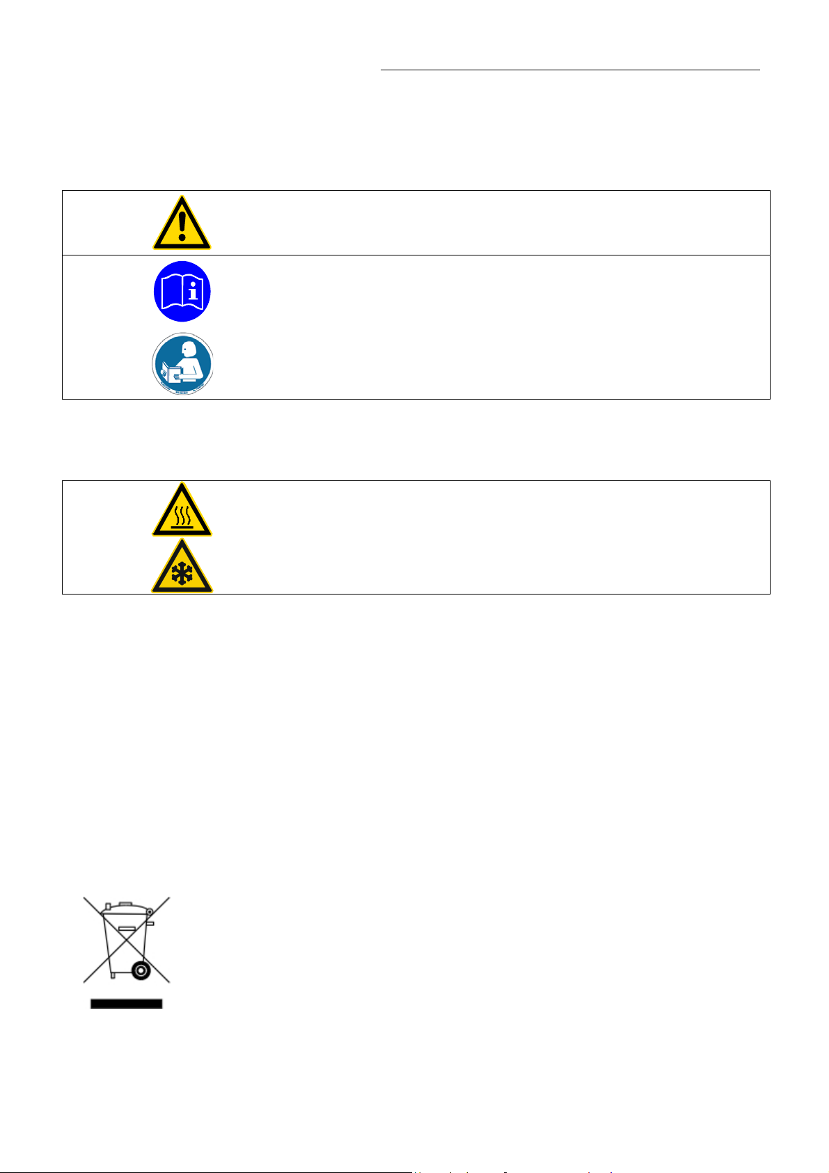
Warning label W00: Colors: yellow, black
Danger area. Attention! Observe instructions.
(operating manual, safety data sheet)
Mandatory label M018: Colors: blue, white
Carefully read the user information prior to beginning operation.
Scope: EU
Semi S1-0701 Table A1-2 #9
Carefully read the user information prior to beginning operation.
Scope: USA, NAFTA
Warning label W26: Colors: yellow, black
Hot surface warning.
(The label is put on by JULABO)
Warning label W017: Colors: yellow, black
Cold surface warning.
(The label is put on by JULABO)
Observe the instructions in the manuals for instruments of a different make that you connect to the circulator,
particularly the respective safety recommendations. Also observe the pin assignment of plugs and technical
specifications of the products.
2.1. Disposal
The product may be used with oil as bath fluid. These oils fully or partially consist of mineral oil or synthetic oil.
For disposal, observe the instructions in the safety data sheets.
Please observe the regulations for disposal which are effective in the country of operation.
This unit contains the refrigerants R404A and R23 – at this time considered not to have any negative effects on
the ozone layer. However, during the long operating period of the unit, disposal prescriptions may change. So
only qualified personnel should take care of disposal.
Valid in EU countries
See the current official journal of the European Union – WEEE directive.
Directive of the European Parliament and of the Council on waste electrical and electronic
equipment (WEEE).
This directive requires electrical and electronic equipment marked with a crossed-out trash
can to be disposed of separately in an environmentally friendly manner.
Contact an authorized waste management company in your country.
Disposal with household waste (unsorted waste) or similar collections of municipal waste is
not permitted!
7
Page 8

Operator responsibility – Safety recommendations
2.2. Warranty conditions
JULABO GmbH warrants its products against defects in material or in workmanship, when used under
appropriate conditions and in accordance with appropriate operating instructions
for a period of ONE YEAR.
Extension of the warranty period – free of charge
With the ‘1PLUS warranty’ the user receives a free of charge extension to the warranty of up to 24 months,
limited to a maximum of 10 000 working hours.
To apply for this extended warranty the user must register the unit on the JULABO web site www.julabo.de
indicating the serial no. The extended warranty will apply from the date of JULABO GmbH’s original invoice.
JULABO GmbH reserves the right to decide the validity of any warranty claim. In case of faults arising either due
to faulty materials or workmanship, parts will be repaired or replaced free of charge, or a new replacement unit
will be supplied.
Any other compensation claims are excluded from this guarantee.
,
8
Page 9
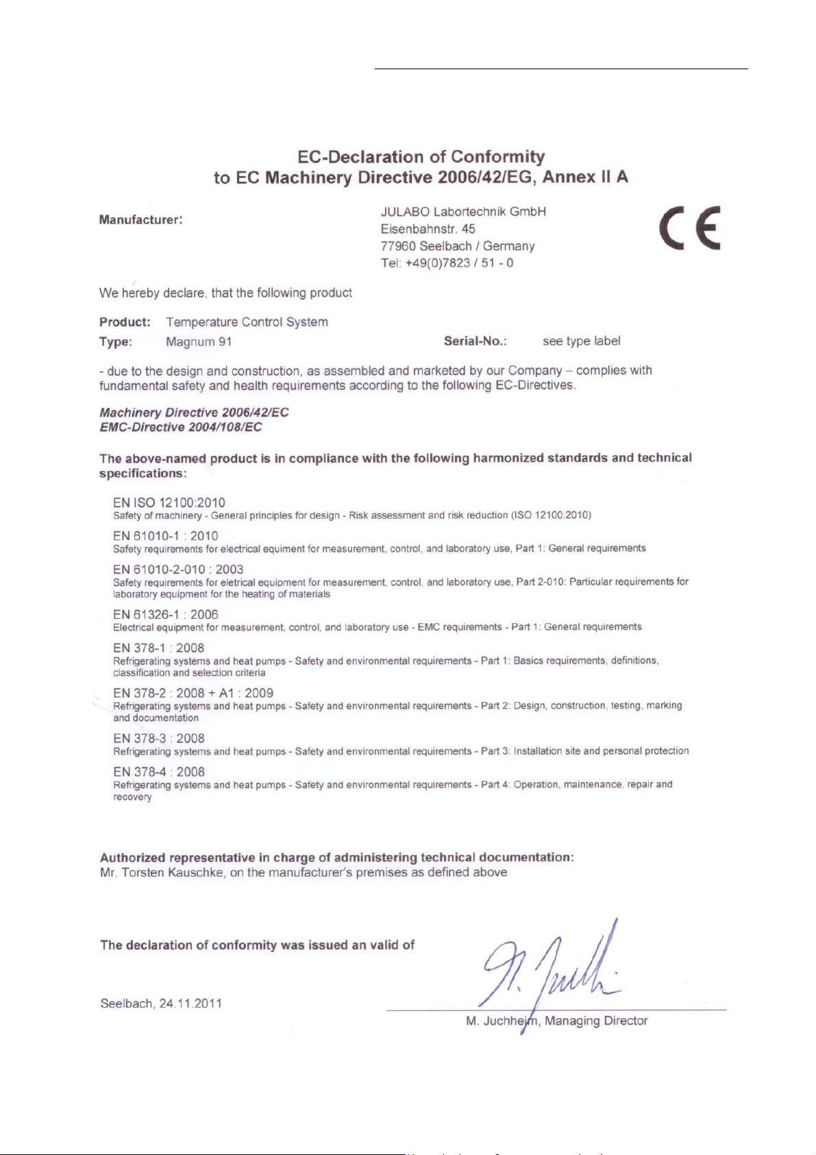
2.3. EEC Declaration of Conformity
Temperature System Magnum 91
9
Page 10

Operator responsibility – Safety recommendations
2.4. Technical specifications
9410191.7 Temperature System
Working temperature range °C -91 ... +250
Temperature stability °C ±0.01 ... ±0.05
Temperature selection: digital
via keypad indication on DIALOG-DISPLAY (LCD)
remote control via personal computer indication on monitor
Temperature indication: VFD COMFORT-DISPLAY
Resolution °C 0.01
Liquid level indication and
pump pressure stage indication
Temperature control ICC - Intelligent Cascade Control
Working temperature sensor Pt 100
Safety temperature sensor Pt 100
Absolute Temperature Calibration
(ATC int) °C ±3
(ATC ext) °C ±10
Heater wattage kW 6.0
Cooling capacity °C
(Medium: Julabo Thermal HL45 │ Ethanol)
pumpe stage 5 kW 3.0 4.8 │ 4.6 4.6 4.5 4.3 2.0 0.5
Cooling compressor 2-stage
Refrigerant R404A / R23
Cooling unit water cooled
Quantity passing l/min 10 (at 15 °C inlet temperature)
Cooling water connectors G 3/4“ external thread
Pressure pump 1) adjustable in five grades Stage 1 2 3 4 5
Prssure max. at 0 Liter bar 0.8 0.95 1.2 1.4 1.9
Flow rate max. at 0 bar l/min 30 35 41 45 50
Filling volume heat exchanger
min. process volume
usable expansion volume
Dimenssions (WxLxH) cm 71x88x165
Weight kg 385
Ambient temperature range °C 5 ... 35
Noise level, 1 m distance dBA 72
Protection class according to IEC 60 529 IP 20
Mains power connection +5 % /-10 % V/ Hz 400 / 50 / 3 Phases
Current input at 400 V max. / phase A 20
VFD COMFORT-DISPLAY
liters
liters
liters
Magnum 91 400 V / 3 Phases / 50 Hz
LCD DIALOG-DISPLAY
(Bar graph in five grades)
200 100 │ 20 0 -20 -40 -60 -80
11.0
21.5
13.0
10
Page 11

Temperature System Magnum 91
Temperature System
Magnum 91 230 V / 3 Phases / 60 Hz
Working temperature range °C -91 ... +250
Temperature stability °C ±0.01 ... ±0.05
Temperature selection: digital
via keypad indication on DIALOG-DISPLAY (LCD)
remote control via personal computer indication on monitor
Temperature indication: VFD COMFORT-DISPLAY
LCD DIALOG-DISPLAY
Resolution °C 0.01
Liquid level indication and
pump pressure stage indication
VFD COMFORT-DISPLAY
(Bar graph in five grades)
Temperature control ICC - Intelligent Cascade Control
Working temperature sensor Pt 100
Safety temperature sensor Pt 100
Absolute Temperature Calibration
(ATC int) °C ±3
(ATC ext) °C ±10
Heater wattage kW 6.0
Cooling capacity °C
200 100 │ 20 0 -20 -40 -60 -80
(Medium: Julabo Thermal HL45 │ Ethanol)
pumpe stage 5 kW 3.0 4.8 │ 4.6 4.6 4.5 4.3 2.0 0.5
Cooling compressor 2-stage
Refrigerant R404A / R23
Cooling unit water cooled
Quantity passing l/min 12 (at 20 °C inlet temperature)
Cooling water connectors G 3/4“ external thread
Pressure pump 1) adjustable in five grades Stage 1 2 3 4 5
Pressure max. at 0 Liter bar 0.8 0.95 1.2 1.4 1.9
Flow rate max. at 0 bar l/min 30 35 41 45 50
Filling volume heat exchanger
min. process volume
usable expansion volume
liters
liters
liters
11.0
21.5
13.0
Dimenssions (BxTxH) cm 71x88x165
Weight kg 385
Ambient temperature range °C 5 ... 35
Noise level, 1 m distance dBA 72
Protection class according to IEC 60 529 IP 20
Mains power connection 0 /-10 % V/ Hz 230 / 3 Phases / 60
Current input at 230 V max. / phase A 35
1)
Pump data in relation to fluids with a specific density of 1 kg/dm3
All measurements have been carried out at: rated voltage and frequency, ambient temperature: 20 °C
Technical changes without prior notification reserved.
11
Page 12

Operator responsibility – Safety recommendations
Electrical connections:
Computer interface RS232 / RS485
Programmer input -100 °C to 400 °C = 0 to 10 V or 0 to 20 mA or 4 to 20 mA
0 to 10 V (0 V = -100 °C, 10 V = 400 °C)
0 to 20 mA (0 mA = -100 °C, 20 mA = 400 °C)
4 to 20 mA (4 mA = -100 °C, 20 mA = 400 °C)
Stand-by input
External alarm device 4-0 V DC / max. 25 mA
External measurement and control sensor Pt100, 4-lead technique
Safety installations and warning functions:
Excess temperature protection >TANK< adjustable from 0 °C ... 320 °C
Excess temperature protection >RES< adjustable from 0 °C ... 220 °C
Low level protection float switch
Liquid level display optical, 5-graded
Classification according to DIN 12876-1 class III
Supplementary safety installations
High temperature warning function optical + audible (in intervals)
Low temperature warning function optical + audible (in intervals)
Supervision of the working sensor plausibility control
Reciprocal sensor monitoring between
working and safety sensors difference >50 K
Alarm indication optical + audible (permanent)
Environmental conditions according to IEC 61 010-1:
Use indoors only.
Altitude up to 2000 m - normal zero.
Ambient temperature: see Technical specifications
Humidity:
Max. relative humidity 80% for temperatures up to +31 °C,
linear decrease down to 50% relative humidity at a temperature of +40 °C
The unit corresponds to Class I
Overvoltage category II
Pollution degree 2
Caution:
The unit is not suitable for use in explosive environment
EMC requirements according to EN 61326-1
This unit is an ISM device classified in Group 1 (using high frequency for internal purposes), Class A (industrial
and commercial range).
12
Page 13
Temperature System Magnum 91
2.5. Cooling water connection
Cooling water pressure (IN / OUT ) max. 6 bar
Difference pressure (IN - OUT ) 3.5 to 6 bar
Cooling water temperature <20 °C
Recommended quality of cooling water:
pH – value 7.5 to 9.0
Sulfate [SO4 2- ] < 100 ppm
Hydrocarbonate [HCO3- ] / Sulphate [SO4 2-] > 1 ppm
Hardness [Ca2+, Mg2+] / [HCO3-] > 0,5 dH
Alkalinity 60 ppm < [HCO3-] < 300 ppm
Conductivity < 500 μs / cm
Chloride (CL-) < 50 ppm
Phosphate (PO43-) < 2 ppm
Ammonia (NH3) < 0.5 ppm
Free Chlorine < 0.5 ppm
Ferri Ions (Fe3+ ) < 0.5 ppm
Mangano Ions (Mn2+) < 0.05 ppm
Carbon dioxide (CO2) < 10 ppm
Hydrosulfide (H2S) < 50 ppm
Content of oxygen < 0.1 ppm
Algae growth impermissible
Suspended solids impermissible
Notice:
Danger of corrosion of heat exchanger due to unsuitable quality of cooling water.
Due to its high content of lime hart water is not suitable for cooling and causes calcination
of the heat exchanger.
Ferrous water or water containing ferrous particles will cause formation of rust even in
heat exchangers made of stainless steel.
Chlorous water will cause pitting corrosion in heat exchangers made of stainless steel.
Due to its corrosive characteristics distilled and deionized water is unsuitable and will
cause corrosion of the bath. .
Due to its corrosive characteristics sea water is not suitable.
Due to its microbiological (bacteria) components which settle in the heat exchanger
untreated and unpurified river water and water from cooling towers is unsuitable.
Avoid particulate matter in cooling water.
Avoid putrid water.
Notice: Cooling water circuit
Risk of oil leaking from the cooling circuit (compressor) of the recirculating cooler into the cooling
water in case of a fault in the circuit!
Observe the laws and regulations of the water distribution company valid in the
location where the unit is operated.
13
Page 14
Operating instructions
ON
Operating instructions
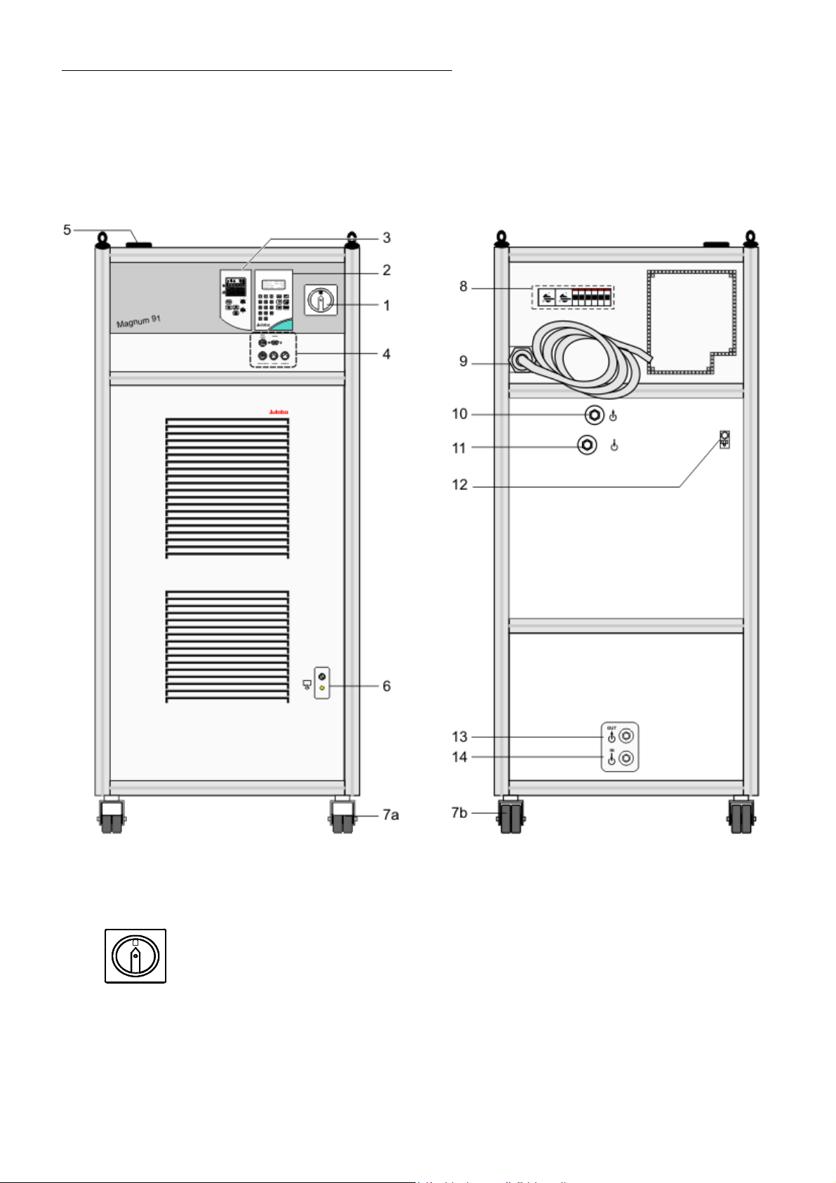
3. Operating controls and functional elements
Front view Rear view
Mains power switch
1
14
Page 15
2 Operating board 1
2.0
Setp: 120. 00 °C
IntAct 21.00°C
ExtAct : 20. 00 °C
Contro l: Intern
2.1
2.2
>Setp. : 12 0. 00 °C
Overt.:255.00°C
Subtmp:-55.00°C
St.Pump: 2
2.3
2.4
>Configuration
Control param.
Profile Start
Int. Programmer
2.5
2.6
2.7
2.8
2.9
ESC
....
Temperature System Magnum 91
DIALOG-DISPLAY (LCD)
Standard indication
Line 1: Setpoint in °C
Line 2: Internal actual value in °C
Line 3: External actual value in °C
Line 4: Control type: internal / external control
Indicating messages (e. g. warnings)
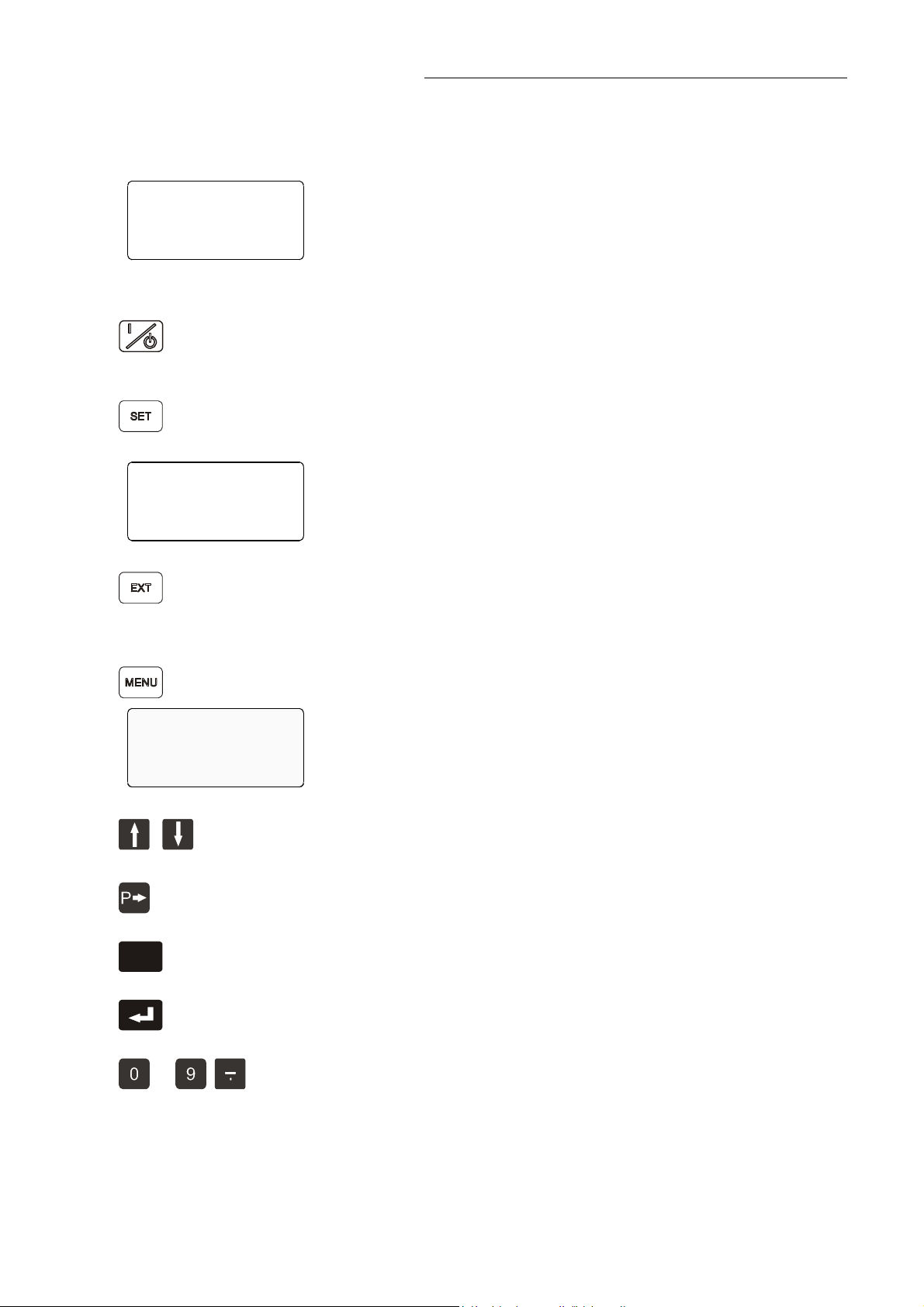
Start / stop key
To switch the circulation pump, heating element and cooling unit.
SET Menu Key - Indicating and setting setpoint values
Set the following values:
in Line 1: the working temperature Setp.:
Line 2: the high temperature limit Overt.:
Line 3: the low temperature limit Subtmp:
Line 4: the pump pressure stage St.Pump:
Control type: internal / external control
To swap, the unit has to be in the STOP MODE.
Indicated in line 4 on the DIALOG-DISPLAY (LCD)
MENU key - for selecting the menu functions
(Menu see page 38)
Cursor keys - Select menu items
P-key Selecting parameters
Escape key 1) Cancel entries
2) Return to a higher menu level
Enter key 1) Store value / parameter
2) Next lower menu level
Numeric keypad: numerals 0 to 9; minus / decimal point
15
Page 16
Operating controls and functional elements
0
0
3 Operating board 2
3.1
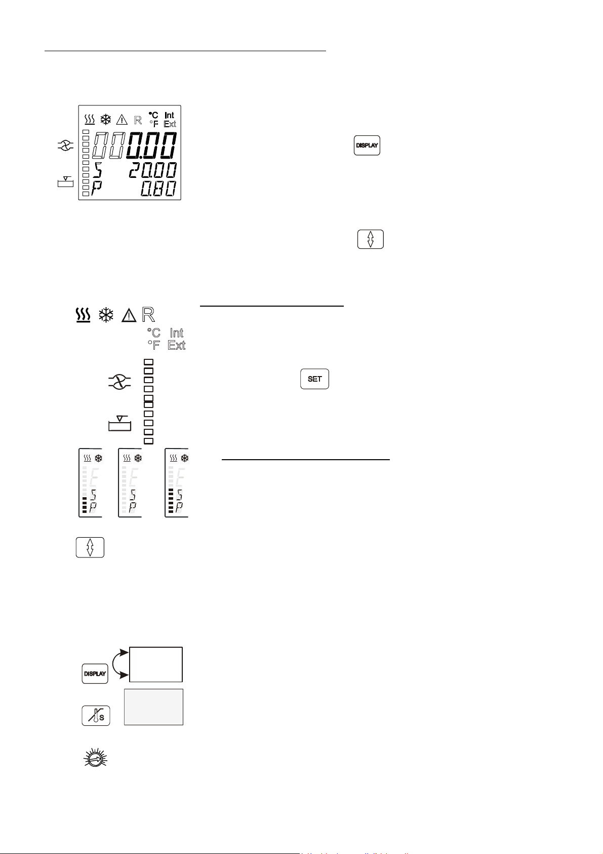
VFD-Info-Display
Header: Control indicators see section 2.2
Line 1: Actual value Int or Ext
3.2
3.21 3.22 3.23
3.3
Int
125.40
S 120.00
3.4
E 120.00
125.40
TANK 15
RES 8
3.5
40
3.6
160
80
240
0
320
°C
To swap, press the key
(see below)
Line 2: Working temp. setpoint, constantly S xxx.xx
or indication of the safety temperature (TANK)
Line 3: Miscellaneous values
To swap, press the key
(see below)
or indication of the safety temperature (RES)
Control indicators in the header:
Heating / Cooling / Alarm / Remote control
Temperature indication Internal or External actual value
Temperature indication in °C (°F not used on Magnum 91)
Display for the adjusted pump pressure stage (five grades),
adjustable via the key
.
Liquid level display (five grades)
for the reservoir.
Liquid level display on VFD-DISPLAY
3.21 Normal operation: 1 ... 4 segments appear
3.22 Low liquid level warning: All segments off
3.23 High liquid level warning: 4 ... 5 segments appear.
Temperature application system overfilled
Taste für Umschaltung der Anzeige in Zeile 3 am VFD
ID 0 Identification no. – not used on Magnum 91
L xx Capacity in %
E xxx.xx or I xxx.xx Actual value (external or internal)
P x.xx Pump pressure in bar
Key to swap line 1 on the VFD
Actual value Int or Ext alternating with line 3
Key to indicate the safety temperature on the VFD
Line 2: TANK - Safety temperature in internal bath
Line 3: RES - Safety temperature in the reservoir
Adjustable excess temperature protection (safety temperature)
Used for setting the safety temperature in the internal bath, called "TANK" on
the display
16
Page 17
130
3.7
60
30
180
10
220
°C
Adjustable safety temperature.
Used for setting the safety temperature in the internal reservoir, called "RES"
on the display
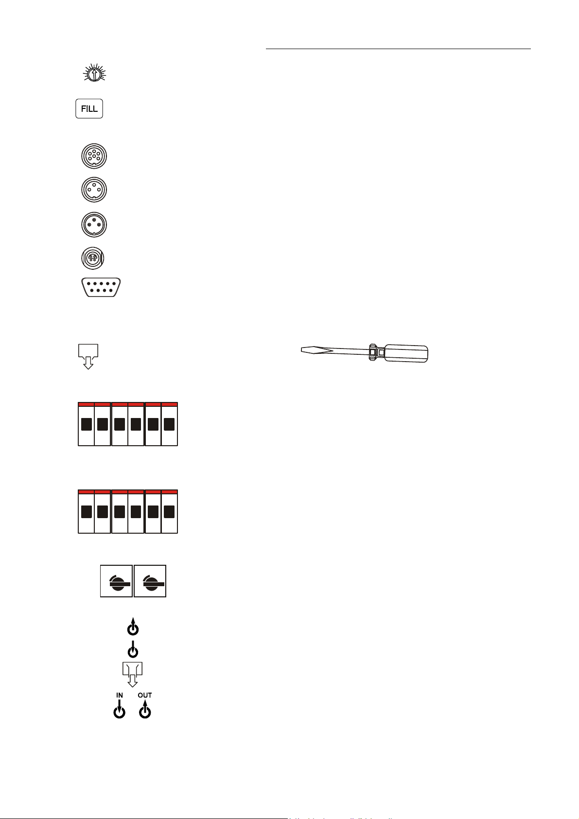
Key for automatic filling and air purge of the unit as well as the connected
3.8
external system.
4 Socket board
Programmer input and temperature recorder output
4.1
REG+E-PROG
Stand-by input (for external emergency switch-off)
4.2
STAND-BY
Alarm output (for external alarm signal)
4.3
ALARM
Connector for external measurement and control sensor
4.4
EXT. Pt100
Temperature System Magnum 91
4.5
SERIAL
Interface RS232/RS485
5 Filling opening
6
Drain port with drain tap
7a /
7b
8
Castor with brake (at the front)
Castor without brake (at the back)
Mains power connection 400 V / 3 Phases / 50 Hz
Mains fuses
F1 and F4 Mains circuit breakers (resettable): 10 A Pump motor
F1 F2 F3 F4 F5 F6
F2 and F5 Mains circuit breakers (resettable): 16 A Heater 1
F3 and F6 Mains circuit breakers (resettable): 16 A Heater 2, Electronics
8
Mains power connection 230 V / 3 Phases / 60 Hz
Mains fuses
F1 and F2 Mains circuit breakers (resettable): 16 A Heater 2, Electronics
F1 F2 F3 F4 F5 F6
F3 and F4 Mains circuit breakers (resettable): 16 A Heater 1
F5 and F6 Mains circuit breakers (resettable): 10 A Pump motor
8
1
0
1
0
2 Motor protection circuit breakers for compressor motors
9 Mains power cable
10
Pump connector: pressure pump M24x1.5
11
Pump connector: return M24x1.5
12
Overflow connector M16x1
13
14
Cooling water connectors IN - inlet OUT - outlet
G3/4" external thread
17
Page 18
Operating controls and functional elements
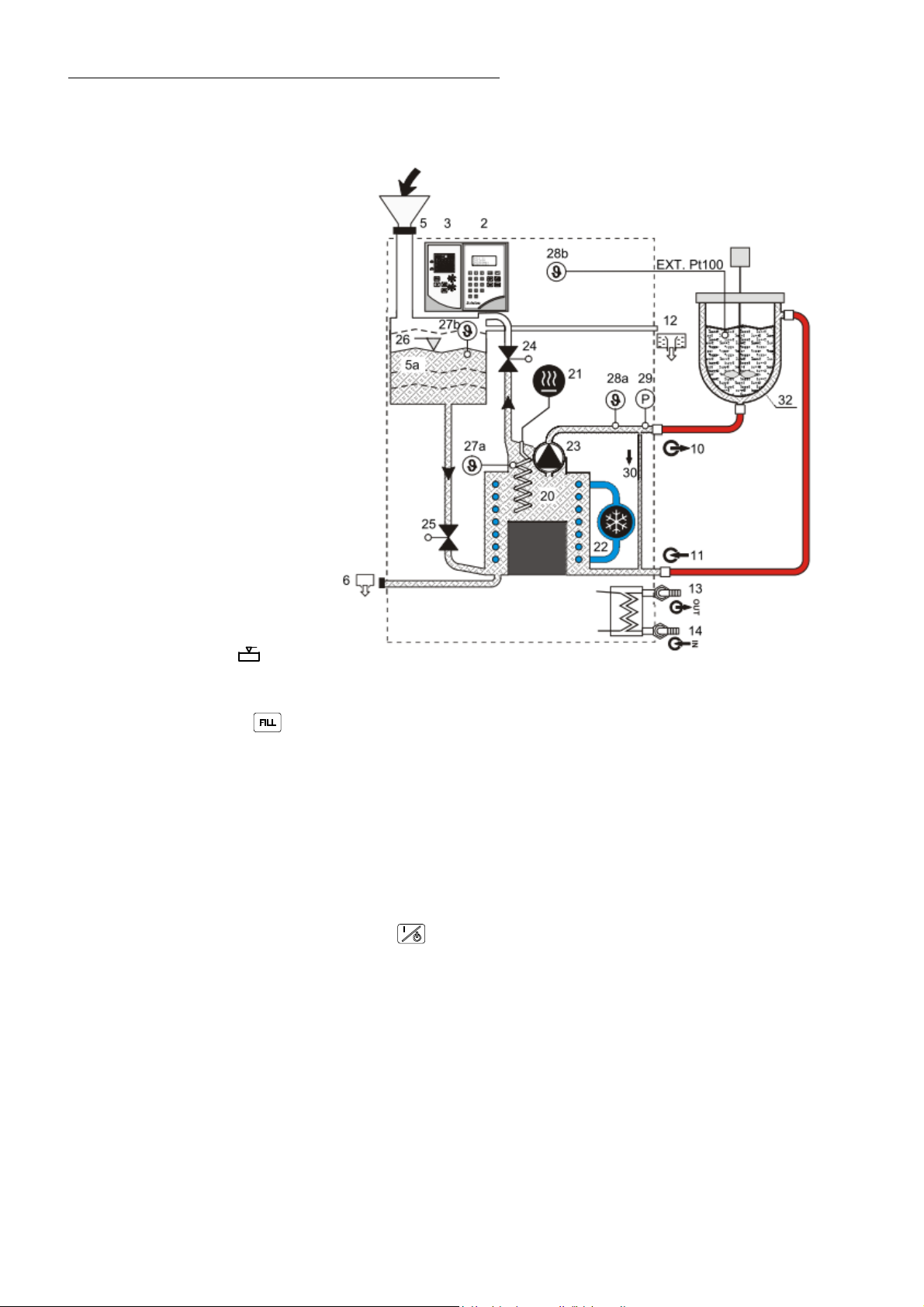
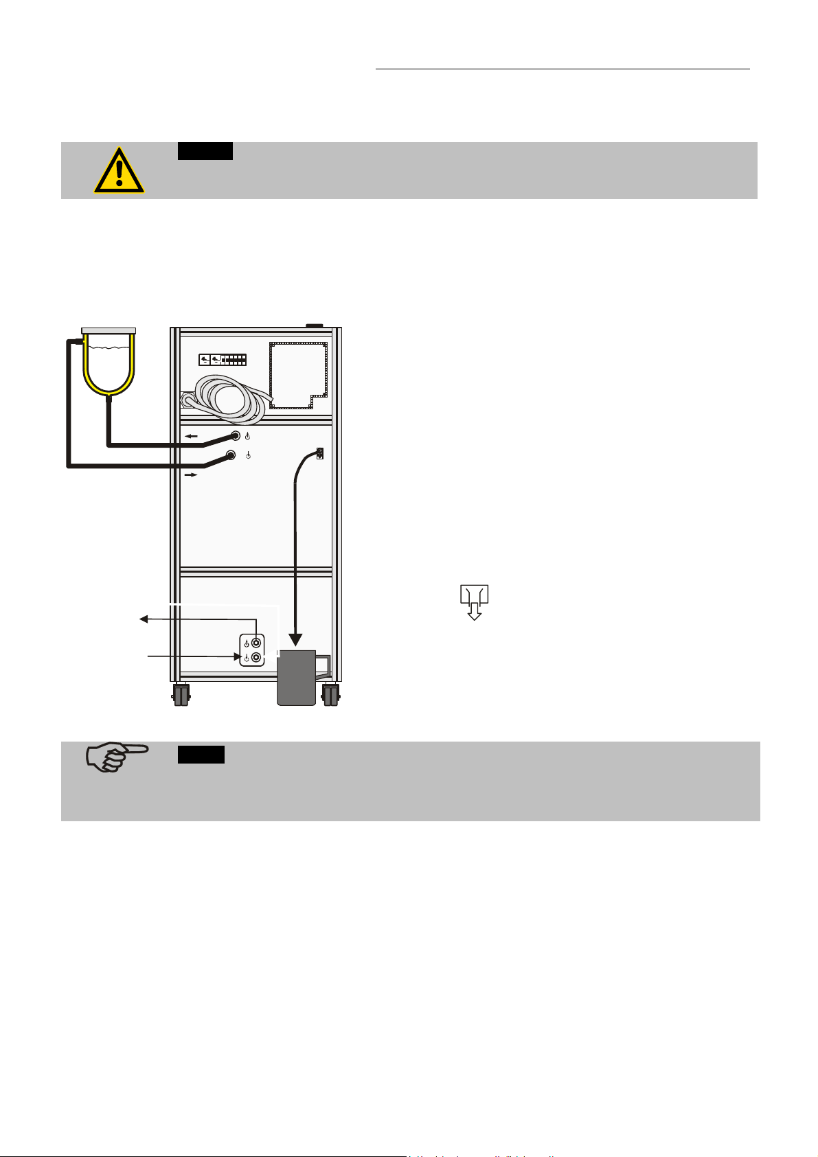
3.1. Description of the Magnum principle
e.g. double-sided glass vessel).
Operating:
The operation of the temperature
system and the indication is
effected via the local operating
board (2, 3).
Filling :
First connect the external
consumer (32). The menu option
>Mode< is set on >Fill<.
The unit is filled at the filling
opening (5) via the internal
reservoir (5a). The bath liquid
flows further into the heat
exchanger (20).
The filling valve (25) represents
narrows. Therefore the filling
should be done slowly.
The air from the heat exchanger
(20) escapes via the venting valve
(24).
In a first step bath liquid is filled in
until the level indication
indicates 3 or 4 segments (see –
Filling volume- page 26).
Then, by pressing the key
is started. In intervals the tempering liquid is pumped via connection (10) into the external system (32) and led
back into the heat exchanger (20) via connection (11). At the end of the filling process the menu option >Mode<
has to be set on >Sys close<.
Working:
In case of a closed external system the filling valve (25) remains open and allows a change in volume of the bath
liquid caused by temperature during operation. In case of emergency it has to be possible that the expanding
bath liquid can drain off at the overflow (12) into a suitable vessel.
The temperature system will be cooled with water (31). Connect the cooling water to the lead in for cooling water
(14). Lead the outflow for cooling water (13) into the locally provided drain respectively backflow.
The temperature system is started with the key
circulating pump (23) start according to the desired adjustments at the operating board (2, 3). In the line to the
pumpe exit (10) the pump pressure (29) and the actual temperature of the internal control sensor (28a) is
permanently measured. If the temperature control has to be effected externally a Pt100 external sensor (28b)
has to be connected and switched over to external control at the operating board.
Safety:
In the internal reservoir (5a) there is the level sensor (26) as well as a safety sensor (27b). The safety sensor
(27a) as high temperature protection is located directly at the heater (21).
If the external circuit is interrupted (e.g. with a shut-off valve), an emergency circuit is maintained via an internal
Bypass (30).
an automatic filling and venting mode with activation of the circulating pump (23)
. The heating (21), the cooling aggregate (22) and the
18
Page 19
4. Safety notes for the user
4.1. Explanation of safety notes
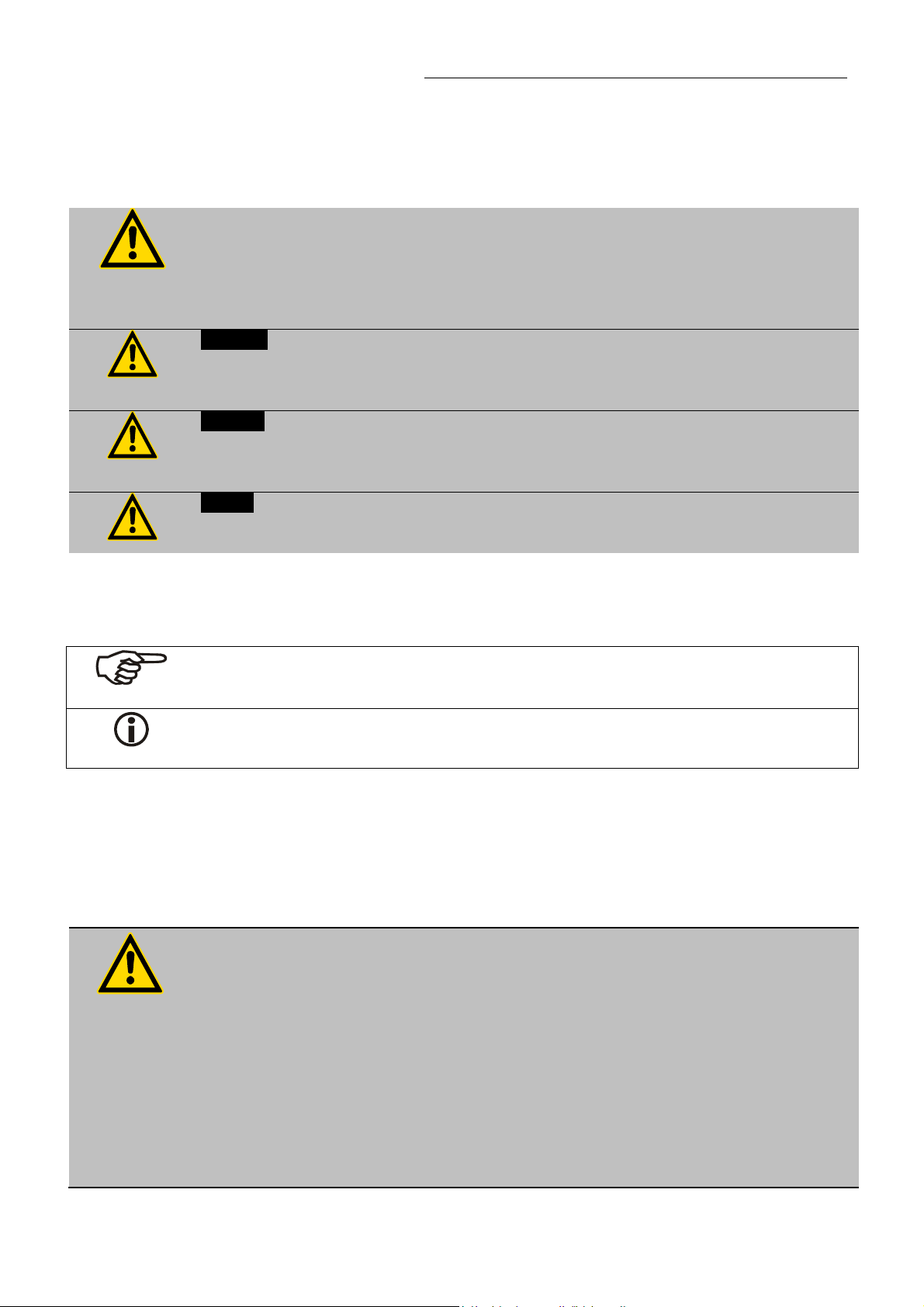
In addition to the safety warnings listed above, warnings are posted throughout the manual.
These warnings are designated by an exclamation mark inside an equilateral triangle.
“Warning of a dangerous situation (Attention! Please follow the documentation).”
The danger is classified using a signal word.
Read and follow these important instructions.
Warning:
Describes a possibly highly dangerous situation. If these instructions are not followed, serious
injury and danger to life could result.
Caution:
Describes a possibly dangerous situation. If this is not avoided, slight or minor injuries could
result. A warning of possible property damage may also be contained in the text.
Notice:
Describes a possibly harmful situation. If this is not avoided, the product or anything in its
surroundings can be damaged.
Temperature System Magnum 91
4.2. Explanation of other notes
Note!
Draws attention to something special.
Important!
Indicates usage tips and other useful information.
4.3. Safety recommendations
Follow the safety recommendations to prevent damage to persons or property.
Further, the valid safety instructions for working places must be followed.
Only connect the unit to a power socket with earthing contact (PE – protective
earth)! This job is to be carried out only by qualified service personnel.
The power supply plug serves as a safe disconnecting device from the line and
must always be easily accessible.
Place the unit on an even surface on a base made of nonflammable material.
Do not stay in the area below the unit.
Make sure you read and understand all instructions and safety precautions listed
in this manual before installing or operating your unit.
Set the value for excess temperature protection.
Observe the fire point of the bath medium used.
Never operate the unit without bath fluid in the bath.
19
Page 20
Safety notes for the user
Pay attention to the thermal expansion of bath oil during heating to avoid
overflowing of the fluid.
Prevent water from penetrating into the hot bath oil.
Do not drain the bath fluid while it is hot!
Check the temperature of the bath fluid prior to draining (by switching the unit on
for a short moment for example).
Use suitable connecting tubing.
Avoid sharp bends in the tubing, and maintain a sufficient distance from
surrounding walls.
Make sure that the tubing is securely attached.
Regularly check the tubing for material defects (e.g. for cracks).
Never operate damaged or leaking equipment.
Always turn off the unit and disconnect the mains cable from the power source
before performing any service or maintenance procedures, or before moving the
unit.
Always turn off the unit and disconnect the mains cable from the power source
before cleaning the unit.
Always empty the bath before moving the unit.
Transport the unit with care.
Sudden jolts or drops may cause damages in the interior of the unit.
Observe all warning labels.
Never remove warning labels.
Never operate equipment with damaged mains power cables.
Repairs are to be carried out only by qualified service personnel.
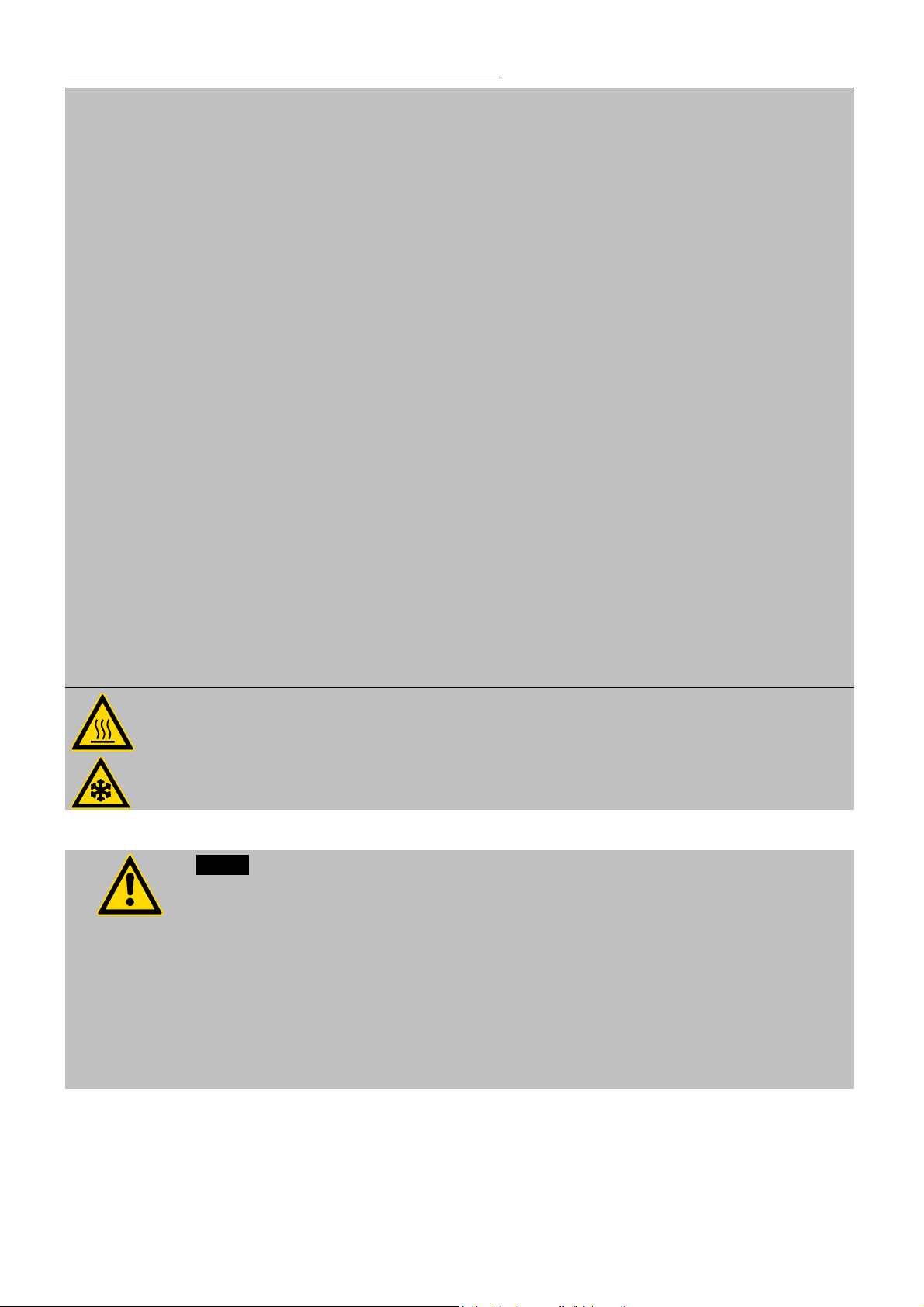
Some parts of the unit and the pump connectors may become extremely warm or cold
during continuous operation. Therefore, exercise particular caution when touching these
parts.
Notice:
Check the safety installations at least twice a year!
Excess temperature protection according to IEC 61010-2-010
With a screw driver turn back the adjustable excess temperature protection until the shutdown point (actual temperature).
Low level protection
To check the function of the float of this unit it cannot be operated manually.
The 5-graded level display should therefore be observed whenver refilling.
If the bath liquid thickens or cracks, the instrument should be cleaned and checked by
qualified personnel.
20
Page 21

Temperature System Magnum 91
Caution:
The temperature controlling i.e. of fluids in a reactor constitutes normal temperature
system practice.
We do not know which substances are contained within these vessels.
Many substances are:
inflammable, easily ignited or explosive
hazardous to health
environmentally unsafe
i.e.: dangerous
The user alone is responsible for the handling of these substances!
The following questions shall help to recognize possible dangers and to reduce the risks to a
minimum.
Are all tubes and electrical cables connected and installed?
Note:
sharp edges, hot surfaces in operation, moving machine parts, etc.
Do dangerous steams or gases arise when heating?
Is an exhaust needed when working?
What to do when a dangerous substance was spilled on or in the unit?
Before starting to work, obtain information concerning the substance and
determine the method of decontamination.
Notice:
When you have finished the application, it is recommended to keep on circulating the liquid in
the bath or the external system for some time. Simultaneously set the working temperature to
+20 °C to allow the temperature in the system to decrease slowly.
Thus fractional over-heating of the bath liquid is prevented.
21
Page 22

Preparations
IN
O
5. Preparations
5.1. Installation
Place the unit on an even surface on a pad made of non-flammable
material. Using the castors (7a, 7b) move the unit to the intended
location. For better stability, apply the holding breaks on the front
casters (7a).
Keep at least 20 cm of open space on the front and rear venting grid.
Do not set up the unit in the immediate vicinity of heat sources and do
not expose to sun light
The place of installation should be large enough and provide sufficient air
ventilation to ensure the room does not warm up excessively because of
the heat the instrument radiates to the environment. (Max. permissible
ambient temperature: 35 °C).
With regard to a disturbance in the cooling loop (leakage), the guideline
EN 378 prescribes a certain room space to be available for each kg of
refrigerant.
The necessary amount of refrigerant is specified on the type plate.
> For 0.52 kg of refrigerant R404A, a room space of 1 m
> For 0.68 kg of refrigerant R23, a room space of 1 m
Only set up the unit in a room where enough fresh air is exchanged.
3
is required.
3
is required.
Before operating the unit after transport, wait about one hour after
setting it up. This will allow any oil that has accumulated laterally during
transport to flow back down thus ensuring maximum cooling
performance of the compressor.
5.2. Cooling water connection
Notice: Cooling water circuit
If the heat exchanger is defective, small volumes of oil may leak into the cooling water.
Therefore never connect the unit to the public water supply!
Observe the laws and regulations of the water distribution company valid in the location
where the unit is operated.
UT
Supply cooling water via the inlet (IN).
Conduct the cooling water via the outlet (OUT) in the respective sink or
return flow circuit.
Cooling water connectors (13, 14) G3/4" external thread
Cooling water see page 13
22
Page 23
5.3. Connect the external system
Caution:
Securely attach all tubing to prevent slipping.
1
010
10
12
11
The temperature systems are designed for temperature
application to closed, external systems (loop circuits). The
temperature application of external, open systems is also
possible. However, this requires a series of special measures
which Julabo cannot influence like e.g. the protection of the
bath liquid from environmental influences such as oxygen and
air humidity.
To profit from the system's rapid performance, ensure the
tubing line between the temperature system and the connected
external system is as short as only possible.
Temperature application to external closed systems.
Remove the cap nuts from the pump connectors
Temperature System Magnum 91
(10, 11) and using tubing connect the external system
(M24x1.5 / wrench 27 mm).
To prevent the formation of bubbles in the loop circuit, the
pressure line (10) is to be connected to the lower nozzle of
the external system.
13
14
Important:
OUT
IN
Connect a piece of tubing to the overflow connector (12)
and drain into a suitable vessel. (M16x1 / wrench 19 mm),
which always has to be placed lower than the exit
„Overflow“.
Notice: Leakage on shaft sealing
The shaft sealings of the pump are never absolutely tight. But this does not have an impact on
the proper functioning of the instrument. The slight leakage that appears ensures good sliding
properties of the sealing. Any excess fluid is drained via the overflow connector (12).
23
Page 24

Preparations
5.3.1. Tubing
Recommended tubing:
Metal tubing, triple insulated, M124x1.5 , Temperature range -100 °C ... +350 °C
Order No. Length max. pressure
8 930 261 1.0 m 6.0 bar 4.0 bar
8 930 262 1.5 m 6.0 bar 4.0 bar
8 930 263 2.0 m 6.0 bar 4.0 bar
8 930 264 3.0 m 6.0 bar 4.0 bar
Warning: Tubing:
At high working temperatures the tubing used for temperature application and cooling water
supply represents a danger source.
A damaged tubing line may cause hot bath liquid to be pumped out within a short
time.
This may result in:
Fire hazard
Explosion hazard
Burning of skin
Difficulties in breathing due to hot atmosphere
Safety recommendations
Employ suitable connecting tubing.
Make sure that the tubing is securely attached.
Avoid sharp bends in the tubing, and maintain a sufficient distance from
surrounding walls.
Regularly check the tubing for material defects (e.g. for cracks).
at 20 °C at 350 °C
24
Page 25

5.4. Bath liquids
Caution:
Carefully read the safety data sheet of the bath liquid used, particulary with regard to the
Recommended bath fluids:
fire piont!
If a bath fluid with a fire point of 65 °C is used, only supervised operation is possible.
The use of water in purified or unpurified form is not allowed.
Examples: Tap water, distilled water, water-glycol mixture, CaCl2-brine
Caution:
Fire or other dangers when using bath fluids that are not recommended:
Please contact JULABO before using other than recommended bath fluids.
Use only nonacidic and noncorrosive bath fluids.
JULABO assumes no liability for damage caused by the selection of an unsuitable bath
liquid.
Unsuitable bath fluids are fluids which, e.g.,
are highly viscous
(much higher than 50 mm2 /s at the respective working temperature)
have a low viscosity and have creep characteristics
have corrosive characteristics or
tend to crack.
No liability for use of other bath fluids!
ATTENTION: The maximum permissible viscosity is 50 mm
Temperature System Magnum 91
See website for list of recommended bath fluids.
Contact: see page 6
2
/s.
Important notice concerning the recommended bath liquids:
Bath liquids with a range of application above the fire point ?
This temperature system is mainly operated in a closed external system (loop circuit). The
contact of the bath liquid with atmospheric oxygen only takes place in the internal reservoir,
which is not located directly in the termperature circuit.
A safety device supervises and controls the the temperature in the internal reservoir.
The temperature of the bath liquid is maintained constant at approx. +20°C
The safety device with an adjustable temperature value >RES< works independently
from the control circuit. When actuating this safety device (too much hot fluid streams
into the internal reservoir) the temperature system is switched off all-polo and
permanently.
Adjust the safety temperature >RES< at at least 25 °C below the fire point of the bath
liquid.
25
Page 26

Preparations
5.5. Power connection
Caution:
The following jobs are to be carried out only by qualified service personnel.
Only connect the unit to a power socket with earthing contact (PE – protective earth)!
Check the protection of the power supply net, and install 35 A fuses if necessary.
Do not use a higher value!
Never operate equipment with damaged mains power cables.
Regularly check the mains power cables for material defects (e.g. for cracks).
We disclaim all liability for damage caused by incorrect line voltages!
Check to make sure that the line voltage matches the supply voltage specified
on the identification plate. Deviations of ±10 % are permissible.
400 V / 3 Phases / 50 Hz
230 V / 3 Phases / 60 Hz
5.6. Filling
Caution:
First connect the external system! See page 23
Use a funnel for filling the system. Spilling bath fluid may result in the fluid to enter the
electronics in the interior of the unit. This must be avoided in any case!
Take care of the bath liquid's changing volume varying with the working temperature of the
Magnum temperature system.
Guideline:
A volume change of 12 % per 100 °C temperature variation is to be considered.
34.5 liters 21.5 liters
Connect the mains power cable (9) to a electricity supply system with
protective earth!
Cable markers: 1 = L1
2 = L2
3 = L3
4 = N
green/yellow = PE
Connect the mains power cable (9) to a electricity supply system with
protective earth!
Cable markers: 1 = L1
2 = L2
3 = L3
gnge = PE
Determination of the required total filling volume:
Filling volume of Magnum 91 + filling volume of external system
Filling volume: Magnum 91 without external system
Indication Quantity Error message
5 segments 34,5 l WARNING CODE 41 (See page 58)
1 segment 21,5 l ----------
26
Page 27

Temperature System Magnum 91
Filling process:
Temp.
FILL
HT
TT
1. First bath fluid is filled in until 3 or 4 segments appear on the level indication
(see –Filling volume- page 26).
The reservoir is filled.
Add the filling volume for the external system (32)!
2. Press the key
3. The liquid level in the unit falls.
4. When marker „C“ is reached, the message CODE 40 (low liquid level warning)
appears.
Then fill in the filling volume required for the external system (32) via the opening
(5).
5. When marker „D“ is reached, the message ALARM CODE 01 (low liquid level
alarm) appears.
to start the automatic filling process.
Filling volume with closed, external system:
Bath fluids change in volume over a temperature increase/decrease. If 1 segment
or 4 segments should appear depends on the application that is to be carried out.
For temperature applications to +230 °C fill up to marker "HT", for applications to
for example –95 °C fill up to marker "TT".
(Temp. FILL = approx. ambient temperature).
27
Page 28

Preparations
A
M
5.6.1. Filling of external, closed systems
Filling is performed in two sections. In section 2, the temperature system
starts an automatic filling process enabling convenient filling.
Notice: First connect the external system! (see page 23)
-OFF-
LARM
CODE 01
Section 1
Connect the unit to a mains power socket (see page 26) and turn on
the unit with the mains power switch (1).
During the self-test all segments of the VFD-Info-Display, all control
indicators and the DIALOG-DISPLAY light up.
After the self-test, the VFD-Info-Display signals low liquid level alarm.
>CODE 01< and a signal tone sounds.
Press enter
to quit the audible signal.
Using a filling funnel, slowly fill in the bath fluid via the filling opening
(5) until the level indication
level indication
5
Section 2
Turn the unit off (approx. 4 seconds) and on again with the mains
.
indicates 3 or 4 segments. Watch the
power switch (1). Wait until the self-test is completed.
Press the key
to start the automatic filling process. On the
VFD-Info-Display „AUTO FILL“ is shown, in intervals.
rd
line of the VFD-
FILL
Soll 1: xxx.xx°C
IntIst: xxx.xx°C
Leistung: 50%
Regelung: Intern
ESC
160
80
240
40
0
320
°C
130
60
180
30
220
10
°C
EXT
SERIAL
Pt100
REG+E-PROG STAND-BYALARM
As soon as the pump pressure indication in the 3
Info-Display
(„P X.XX“) has scaled up to at least 0.1 bar, the tempering liquid is
pumped into the external system. In intervals of 10 seconds bath
liquid is pumped into the external system - air purge is carried out in
the breaks.
Notice: The filling mode has to stay activated for at least 5 minutes
in order to fully de-air the system.
-OFF-
AUTO
FILL
-OFF-
Warning
CODE 40
The liquid level in the unit falls.
In case of a WARNING >CODE 40< again slowly fill in bath fluid into
the opening (5).
Watch the level indication
.
In case of a ALARM >CODE 01< return to the final condition of
section 1 and restart section 2.
If the liquid level display remains unchanged after some minutes,
complete filling according to the application task.
See page 27 - marker "HT" or "TT".
Pump
>Pump OFF
odu: Sys close
Press
In the submenu >Pump< the unit has to be set on
>Mode:< >sys close< . (see page 29)
The unit is now ready for operation .
to finish the automatic filling process.
28
Page 29

Temperature System Magnum 91
Adjusting Mode:
Press the respective keys in the following order:
1. MENUE key
2. Cursor key
3. Enter key
4. Cursor key
5. P- key
6. Enter key
7. Escape key
1x
up to Submenu "Pump"
1x
1x up to "Pump"
sys open / sys close / fill / drain
1x
ESC
2x
The DIALOG-DISPLAY (LCD) helps to follow up the individual
settings.
The VFD-Info Display shows the recently chosen operating status
for approx. 3 seconds.
Switch over to > sys open < OPEN SYSTEN
Switch over to > sys close < CLOSED SYSTEM
Switch over to > fill < FILL SYSTEM
Switch over to >drain< DRAIN SYSTEM
Notice concerning the filling
The temperature system was emptied last, therefore the menu option >Mode<
now still stands on >drain<. In the configuration of this unit the >Mode< >fill<
means the same as >drain< and therefore does not have to be adjusted.
Explanation of terms:
>Mode: sys close< stands for closed, external system
(Magnum principle page 18)
>Mode: sys open< stands for open external system
(not recommended by JULABO)
29
Page 30

Preparations
5.7. Degasifying
78.00
S 180.00
-DEGAS-
Srtp: 180.00°C
IntAct 78.00°C
ExtAct: --.--°C
Control: Intern
If the temperature system is operated in a closed, external consumer,
>Mode: sys close<, an automatic degasifying is carried out after the start..
During the degasifying unwelcome components of the bath liquid are are
drawn off .
Examples:
Air bubbles which were enclosed in the bath liquid during the filling for
the unit.
Slightly volutile components which are eventually in the fluid.
Eventually existing water components, which reached the bath liquid
during the storage.
When operating in the >Mode: sys open< there is no need for
degasifying, because the unwelcome components can escape via the
open bath tank.
The automatic degasifying is a part of the program in the unit, which is
always active in the background. Experience shows that the activity is
only noticed after a first or new filling of the unit.
During the heating-up phase, e.g. to a working temperature of 180°C, the
VFD-Info-Display shows >DEGAS<.
Parallely to this, in line 4 in the DIALOG-DISPLAY the message
>Degasifying active< is inserted. In this phase the temperature rise is
stopped, the pump motor and the ventilation valve are activated
alternately (audible). During the heating-up phase this degasifying mode
can be repeated with the most different temperatures.
The automatic degasifying can be stopped by :
degasing activ
Operating the key
adjusting the set temperature on at least 50°C lower than the
or
current set temperature.
Caution:
With different substances the change-over to the steam phase and therefore also an
enormous change of volume is carried out very quickly. The fluid, for which there is no more
room in the internal reservoir, now has to drain off controlled via the overflow.
Important:
Connect a piece of tubing to the overflow connector (14) and drain into a suitable vessel. (min.
2 liters) (M16x1 / wrench 19 mm), which always has to be placed lower than the exit
„Overflow“
30
Page 31

0
M
5.8. Draining
Notice:
Do not drain the bath fluid while it is hot!
Store and dispose the used bath liquid according to the laws for environmental
Please observe the regulations for disposal which are effective in the country of
-OFF-
S 20.0
P x.xx
Pump
>Pump OFF
odu: drain
Temperature System Magnum 91
Check the temperature of the bath fluid prior to draining (by switching the unit on for a
short moment, for example).
protection.
operation.
Turn on the temperature system with the mains power switch or
press the stop key
MODE.
In the submenu >Pump<, set the menu items >Mode< to
>drain<.
(see page 29 Adjusting Mode:)
Place a suitable vessel for accepting the used bath liquid
underneath the drain.
Slide a short piece of tubing onto the drain port and hold the end
into the vessel..
to make the unit enter the STOP-
Unscrew the drain screw by some turns.
The unit has two drain screws. Both have to be used.
The liquid level in the unit falls.
Now the VFD-Display of the unit should show low level,
WARNING >CODE 40< and then ALARM >CODE 01<.
Press enter
to quit the audible signal.
Drain the external system:
At the upper nozzle of the external system, disconnect the
tubing to the pump connector "return" (12) until an air
stream moves in.
Tighten the drain screw after draining the unit.
(Cleaning the unit see page 73)
31
Page 32

Operating procedures
6. Operating procedures
6.1. Switching on / Selecting the language
Switching on:
IN
The unit is operated by turning the mains power switch (1).
The integrated pilot lamp illuminates.
JULABO
Magnum
91
V1.91-AE
During the self-test all segments of the VFD-Info-Display, all control
indicators and the DIALOG-DISPLAY light up.
Then the software version number (example: V1.91-AE) appears for
a short moment and the message "OFF" indicates the unit is ready to
operate.
Message >WAIT< when adjusting >Mode: sys close<:.
During the message >WAIT< the ventilation valve is opened for 10
seconds. So, the air which has eventually been collected during the
standstill, can escape.
Soll: 20.00°C
IntIst xxx.00°C
>Konfiguration
ExtIst:
Regelparameter
Konfiguration
Regelung:
Identif. xxxxx
Sollwert xxxxx
Autostart xxx
Standby xxxx
>Sprache xxxxxxx
Setp.: 20.00°C
IntAct xxx.xx°C
ExtAct: xx x.xx °C
Control: intern
The unit returns to the previous operating mode that was active
before it was turned off:
keypad control mode
(manual operation via the unit itself/RD)
or
remote control mode
(operation via PC).
Selecting the language:
There are two options for the language of the DIALOG-DISPLAY (LCD):
German or English. Select the desired language in the MENU level under
the submenu >Configuration.
Press the respective keys in the following order:
1. MENU key
2. Enter key
3. Cursor key
4. P-key
5. Enter key
6. Escape key
The DIALOG-DISPLAY (LCD) helps to follow up the individual settings
(example: swap the language from German to English).
1x
1x
up to Submenu "Sprache/Language"
1x
1x
ESC
2x
32
Page 33

0
0
7. Manual operation
7.1. Start - Stop
Temperature System Magnum 91
Setp: 20.00°C
IntAct: 21.00°C
ExtAct: --.--°C
Control: Intern
21.0
S 20.0
P x.xx
Setp.: 20.00°C
IntAct 21.00°C
ExtAct : --. -- °C
Control: Intern
Stop-Mode
Notice:
The message >SELECT SYSTEM<is a demand to make an adjustment in the menu >Pump<
according to the connected system. The insertion is effected cyclicly until the adustment has
been made (see page 29 Adjusting Mode:)
In the >Mode< > fill < or. >drain<>SELECT SYSTEM< is shown when starting.
Notice:
For physical reasons, refrigeration units provide full cooling performance only after some
minutes. After the start up to 5 minutes can go by, until the cooling capacity is given.
Start:
IN
Press the start/stop key .
The actual bath temperature is displayed.
For approx. 3 seconds the VFD-Info-Display shows the adjusted
>Mode< .
Adjustment > sys open < OPEN SYSTEM
Adjustment > sys close < CLOSED SYSTEM
The temperature system runs.
Stop:
IN
Press the start/stop key .
The VFD indicates "OFF" and the message STOP-MODE flashes in
line 4 on the LCD.
-OFF-
S 20.00
P x.xx
The unit also enters the safe operating state "OFF" after a mains power interruptance. The
temperature values entered via the keypad remain in memory. With the temperature system in
keypad control mode, press the start/stop key to restart operation. With the instrument in
remote control mode, the personal computer must first resend the parameters set via the
interface before the temperature system may be restarted.
33
Page 34

Manual operation
7.2. Direct setting of the working temperature
Setp.: 20.00°C
IntAct 21.00°C
ExtAct : --. -- °C
Control: Intern
This setting may be carried out with the temperature system being in
operating state Start or Stop!
The value previously set appears on the DIALOG-DISPLAY (LCD)
(example: 20.00 °C).
A flashing segment indicates that a value needs to be entered.
Use the keypad to enter the new value and press enter
store the selected value.
(examples: 120.00 °C; 228.50 °C; -15.00 °C).
7.3. Settings in the SET menu
Press the key
the DIALOG-DISPLAY (LCD).
>Setp.: 120.00°C
Overt.:255.00°C
Subtmp:-55.00°C
St.Pump: 2
Set the following values:
in Line 1: the working temperature in °C Setp.:
Line 2: the high temperature limit in °C Overt.:
Line 3: the low temperature limit in °C Subtmp:
Line 4: the pump pressure stage St.Pump:
Enter the desired values via the keypad. Settings may be carried out
with the temperature system being in operating state Start or Stop!
Use the cursors
Press escape
to call up the SET menu. It is then indicated on
to swap the lines.
ESC
to quit the SET menu.
to
7.3.1. Setting the working temperature
>Setp. : 200 .0 0° C
Overt.: 255.00°C
Suptmp: -55.00°C
St.Pump: 2
>Setp. : 12 0. 00 °C
Overt.:255.00°C
Subtmp:-55.00°C
St.Pump: 2
34
>Setp.: Setting the working temperature
Setting in line 1.
The value previously set appears on the DIALOG-DISPLAY (LCD)
(example: 100.00 °C).
A flashing segment indicates that a value needs to be entered.
Use the keypad to enter the new value
(examples: 120.00 °C; 228.50 °C; -15.00 °C).
Press enter to store the selected value.
Page 35

7.3.2. Warning functions
Temperature System Magnum 91
The high and low temperature warning functions accompany the working
temperature value. An audible signal sounds in intervals when the actual
temperature exceeds one of the set limits (patented).
The corresponding message appears in line 4 on the DIALOG-DISPLAY
(LCD).
Setp.: 120.00°C
>Overt.:130.00°C
Subtmp:-55.00°C
St.Pump: 2
Setp.: 120.00°C
Overt.:130.00°C
>Subtmp:110.00°C
St.Pump: 2
Note:
The warning functions will only be triggered when the actual bath temperature, after start from
the "OFF" or "rOFF" mode, lies within the set limits for 3 seconds.
>Overt: Setting the high temperature limit
Setting in line 2.
The value previously set appears on the DIALOG-DISPLAY (LCD).
A flashing segment indicates that a value needs to be entered.
Use the keypad to enter the new value
(examples: 130.00 °C; -13.00 °C).
Press enter to store the selected value.
>Subtmp: Setting the low temperature limit
Setting in line 3.
The value previously set appears on the DIALOG-DISPLAY (LCD).
A flashing segment indicates that a value needs to be entered.
Use the keypad to enter the new value
(examples: 110.00 °C; -17.00 °C).
Press enter to store the selected value.
Example:
Setp: 120. 00 °C
IntAct 130.50°C
ExtAct : --. -- °C
Control: Intern
Excess temp.
°C
150
130
120
110
20
t
The corresponding message appears in line 4 on the DIALOG-DISPLAY
(LCD).
35
Page 36

Manual operation
A
7.3.3. Setting the pump pressure stage
The pressure of the circulation pump is adjustable in five grades.
After setting, the VFD-Info-Display indicates the corresponding
Setp.: 120.00°C
Overt.:130.00°C
Subtmp:110.00°C
>St.Pu mp : 4
value.
>St.Pump: Setting the pump pressure stage
Setting in line 4.
The value previously set appears on the DIALOG-DISPLAY (LCD).
A flashing segment indicates that a value needs to be entered.
Use the keypad to enter the new value
(example: 4).
Press enter to store the selected value.
Note:
The mechanical rotation of the circulation pump produces heat that is radiated into the bath
liquid. The lowest working temperature may thus only be reached if the pump pressure is set
to grade 1.
7.4. Setting the safety installations
TANK 150
RES 100
160
80
40
0
60
30
10
320
°C
130
220
°C
-OFF-
LARM
CODE 14
ALARM!
IntAct : xx. xx °C
ExtAct : --. -- °C
Temp/level alarm
240
180
This safety feature functions independent of the regulator circuit. When the
temperature of the bath liquid has reached the safety temperature, a
complete shutdown of the heater and pump is effected.
Excess temperature protection in the heat exchanger >TANK<
(Excess temperature protection according to IEC 61010-2-010)
Press the key
>TANK< on the VFD-Info-Display and using a screwdriver
simultaneously turn the setting screw to the desired value
(example: 150 °C).
Setting range: 0 °C to 320 °C
in 2 °C steps
The alarm is indicated by optical and audible signals (continuous tone).
The error messages opposite appear on the DIALOG-DISPLAY (LCD) and
VFD-Info-Display.
to indicate the safety temperature value in line 2
36
Page 37

Temperature System Magnum 91
A
3
-OFF-
LARM
CODE 1
ALARM!
IntAct : xx. xx °C
ExtAct : --. -- °C
RESERVOIR
Excess temperature protection in the reservoir >RES<
This supplementary safety installation supervises and controls the
temperature of the bath liquid in the internal reservoir.
Press the key
>RES< on the VFD-Info-Display and using a screwdriver simultaneously
turn the setting screw to the desired value
(example: 100 °C).
Setting range: 10 °C to 220 °C
in 2 °C steps
The alarm is indicated by optical and audible signals (continuous tone).
The error messages opposite appear on the DIALOG-DISPLAY (LCD) and
VFD-Info-Display.
Press enter
to indicate the safety temperature value in line 3
to quit the audible signal.
After eliminating the malfunction, turn the mains power switch off and
on again to cancel the alarm state.
Warning:
Recommendation for external, closed systems:
Set the safety temperature >TANK< 15 °C above the working temperature setpoint.
The safety temperature value >RES<should be set at least 25 °C below the fire point of
the bath liquid used.
Important:
Check the safety installations at least twice a year! . See page 20
37
Page 38

Menu functions
0
0
7.5. Internal / external control
ext. Pt100
-OFF-
S xx.xx
P x.xx
Setp: 120. 00 °C
IntAct 21.00°C
ExtAct : 20. 00 °C
Contro l: Intern
Setp: 120. 00 °C
IntAct 21.00°C
ExtAct : 20. 00 °C
Contro l: Extern
ESC
The temperature system offers the possibility of internal temperature
control in the internal bath or external control directly in an external
system.
Setup for external control:
®
Connect a Pt100 sensor to the socket "EXT" of the Presto
system, if necessary perform a calibration using the "ATC Ext:" function
(see page 55) and then securely fix the sensor in the external system.
To swap internal to external control:
Press the key
type.
The DIALOG-DISPLAY (LCD) indicates the effective control type in
line 4
>Control: intern< or > Control: extern<
Press the start/stop key .
Temperature indication:
The DIALOG-DISPLAY (LCD)
simultaneously indicates both actual temperatures.
The VFD-Info-Display
indicates the actual temperature in line 1. In the header the
corresponding symbol >Int< or >Ext< is illuminated.
in operating state "OFF" to select the control
temperature
Int
21.00
S 120.0
E 20.0
8. Menu functions
Notice
Place the external sensor into the temperature-controlled medium and securely fix the sensor.
Press the key
It is useful, to set line 3 to show the actual temperature
>E xx.xx°C< by pressing the key
Press the MENU key
Use the up/down cursor keys
submenu and press enter
Press escape
to swap the display.
.
to enter the menu level.
to select the desired
.
ESC
to return to the previous menu level.
38
Page 39

Temperature System Magnum 91
>
>
>
>
>
>
>
(
Setp.: 50.00°C
IntAct: 50.00°C
Power: 50 %
Control: intern
>Configuration
Control param.
Profile Start
Int.Programmer
Inputs/Outputs
Limits
Interface
Temp.Sensor
Pump
Int.Programmer
>Edit
Delete
Set Clock
Configuration
>Identif. off off/once/always
Setpoint keyb keyb/eprog/RS232 or RS485
Autostart on on/off
Standby no yes/no
Language german german/engl.
IdentNo 0 0 ... 999
Control param.
>Xp = 2.5 K
Tn = 220 s
Tv = 1 S
Xpu= 5.0K
CoSpeed= 0.0
DynInt=aperiod. aperiod./standard
or PROFI
Example
>Start Profile 0
at Step 0
Loops 1
Start no yes/no/time
Edit Profile: 0
Step: 8
Setp: °C
Time[h.m] xx:xx
Delete Prof. 0
from Step 0
to Step 30
delete yes yes/no
time
>hour.min 06:00
Day.Mon 15:11
Year 2009
Start yes
Starttime: 06:00
Date: 15:11
*** wait ***
acttime 02:32:56
hour.min 11:09
Day.mon 18.04
Year 2009
11:09:33
Inputs/Outputs
>Chan.1:Setpoint
Chan.2: ActInt
Chan.3: ActExt
EPROG: Current
Limits
>IntMax 250.00°C
IntMin -50.00°C
Band 30K
HeatingMax 100%
CoolingMax 100%
Interface
>Type RS232 RS232/RS485
Baudrate 4800 4800/9600
Parity no no/odd/even
Handshake softw softw/hardw
Sensors
>ATC Int: 0.00K
ATC Ext: 0.00K
Pump
>Pump OFF OFF/ON
Mode sys closed sys closed/fill/drain
REM: sys = external System
Chan.1:Setpoint Setpoint/ActInt/ActExt/Power
0V = 0.0°C
10V = 100.0°C
Chan.2: ActInt Setpoint/ActInt/ActExt/Power
0V = 0.0°C
10V = 100.0°C
Chan.3: ActExt Setpoint/ActInt/ActExt/Power
0mA = 0.0°C
20mA = 100.0°C
Region: 0-20mA 4-20mA/0-20mA
EPROG: Current Current/Voltage
L Value 0.0°C
H Value 300.0°C
ExtSet 50.0°C
at RS485: >Address 23 0 - 127)
Select parameter
Set value via keypad
39
Page 40

Menu functions
8.1. Configuration
>Configuration
Controlparam.
Profile Start
Int.Programmer
Inputs/Outputs
Limits
Interface
Temp.Sensor
Pump
Configuration
Identif. xxxxx
Setpoint xxxxx
Autostart xxx
Standby xxxx
Language xxxxxx
IdentNo x
By means of the configuration functions, operation of the instrument can
be optimized for the current application.
Press enter
Use the up/down cursor keys
A flashing line indicates that a value needs to be entered.
Press the P-key
Press escape
to select the configuration submenu.
to select the desired option.
to select the parameter and press enter .
ESC
to return the previous menu level.
> Identification
When performing an identification for the controlled system (temperature
application system), the control parameters Xp, Tn and Tv will be
automatically determined and stored.
Possible parameters:
off - no identification.
The control parameters ascertained during the last identification are
used for control purposes.
once - single identification
The instrument performs a single identification of the controlled
system after start.
After the identification process the parameter is automatically set to
"off".
always - continual identification
The instrument performs an identification of the controlled system
whenever a new setpoint is to be reached.
NOTE: Use this setting only when the temperature application
system changes permanently.
Important:
For physical reasons, refrigeration units provide full cooling performance
only after some minutes. During identification this is given consideration
by waiting for 5 minutes after switch-on.
40
Page 41

Temperature System Magnum 91
Note:
Requirement for an identification of the controlled system:
The temperature system must heat to a setpoint temperature at least
10 °C above the previous setpoint using the adjusted heating power.
When the adjusted control parameters Xp, Tn and Tv are too high,
this requirement may not be given with respect to on how much the
setpoint temperature has to change. In this case, prior to carrying out
an identification in the "OFF" state, set the control parameters to
lower values.
Recommended setting for internal control:
Xp = 8 K¸
Tn = 80 s,
Tv = 8 s
Setp.: 50.00°C
IntAct: 50.00°C
Eprog: 50.00°C
ExtAct: 50.00°C
IntAct: 50.00°C
Rs232: 50.00°C
Control: intern
Power: 50 %
IntAct: 50.00°C
Control: intern
Power: 50 %
Control: intern
> Setpoint
The instrument provides three possibilities for setpoint selection. The
active mode is indicated on the DIALOG-DISPLAY (LCD).
The control indicator >R< (REMOTE) is illuminated in the header of the
VFD-Info-Display if setpoint selection is effected via the EPROG or
SERIAL input.
Possible parameters:
R
S xx.xx
P x.xx
REG+E-PROG
SERIAL
keyb- Setpoint setting via keypad (Setp.:) or via the integrated
programmer.
eprog - Setpoint setting via the analog interface REG+E-PROG (3.1)
connection with an external voltage or current source or a
programmer. (see page 51)
RS232 - Setpoint setting via the serial RS232/RS485 interface (3.5)
through a PC or superordinated data system.
>Autostart
Note:
The temperature system has been configured and supplied by JULABO
according to N.A.M.U.R. recommendations. This means for the start
mode, that the unit must enter a safe operating state after a power failure
(non-automatic start mode). This safe operating state is indicated by
"OFF", resp. on the VFD-Info-Display. A complete shutdown of the main
functional elements such as heater and circulation pump is effected
simultaneously.
Only with setpoint adjustment the AUTOSTART-function can be executed
via >Taste< and >EPROG< (see above).
41
Page 42

Menu functions
0
Should such a safety standard not be required, the AUTOSTART function
(automatic start mode) may be activated, thus allowing the start of the
instrument directly by pressing the mains power switch or using a timer.
Warning:
For supervised or unsupervised operation with the AUTOSTART function, avoid any
hazardous situation to persons or property.
The instrument does no longer conform to N.A.M.U.R. recommendations.
Take care you fully observe the safety and warning functions of the instrument.
If the setpoint is given via the serial interface, no AUTOSTART is possible.
STAND-BY
Possible parameters:
on - AUTOSTART on
off - AUTOSTART off
>Stand-by input
External stand-by for emergency switch-off
(connector - see page 63)
Possible parameters:
no - stand-by input is ignored
yes - stand-by input is active
> Language
-OFF-
S xx.xx
ID
There are two options for the language of the DIALOG-DISPLAY (LCD):
German or English.
Possible parameters:
German (deutsch)
English (engl).
>IdentNo
There is no ident number for this unit.
42
Page 43

8.2. Control parameters
Temperature System Magnum 91
Configuration
>Control param.
Profile Start
Int.Programmer
Inputs/Outputs
Limits
Interface
Temp.Sensor
Xp =
Control param.
>Xp = 2.5 K
Tn = 220 s
Tv = 1 S
When performing an identification for the controlled system (temperature
applications system) (see page 40), the control parameters Xp, Tn, Tv and
Xpu will be automatically determined and stored.
Each parameter may be manually set via the keypad if necessary, to allow
optimum control performance.
Press enter
Use the up/down cursor keys
to select the submenu "control parameters".
to select the desired option. A
flashing segment indicates that a new value needs to be entered.
Use the numerals to set the value and then set with enter
(example: Xp = 2.5 °C).
or at >DynInt<
Press the P-key to select the parameter and press enter
.
ESC
Press escape
to return to the previous menu level.
Proportional range >Xp<
The proportional range is the range below the selected temperature value
in wich the the control circuit reduces the heating power from 100 % to 0
%.
Resetting time >Tn< (Integral component)
Compensation of the remaining control deviation due to proportional
regulation. An insufficient resetting time may cause instabilities to occur.
Excessive resetting time will unnecessarily prolong compensation of the
control difference.
Lead time >Tv< (Differential component)
The differential component reduces the control settling time. An
insufficient lead time will prolong the time required to compensate for
disturbance effects and cause high overshooting during run-up. An
excessive lead time could cause instabilities (oscillations) to occur.
Proportional range >Xpu<
The proportional range Xpu of the cascaded controller is only needed for
external control.
43
Page 44

Menu functions
°C
°C
standard
temp. stability
aperiod.
setpoint
standard
temp. stability
aperiod.
>DynInt< - Dynamics
This parameter affects the march of temperature only in case of
internal control (see page 38)
Adjustable parameter:
standard The temperature rises quicker, however can
t
aperiod. The temperature rises chronologically without
overshoot up to 5 %. If a ramp is defined, the march
of temperature often follows this ramp.
overshoot.
°C
°C
temperature ramp
Temp. intern
Temp. extern
5
3
0
setpoint
Optimization instructions for the PID control parameters:
optimum setting
With both adjustments a sufficient temperature stability is reached
after approximately the same time.
t
>CoSpeed< 0 up to 5
This parameter affects the march temperature only in case of
external control (see page 38).
The adjustment affects the calculation of the control parameter when
identifying and so the control course.
t
The heat-up curve reveals inappropriate control settings.
°C
°C
44
t
Inappropriate settings may produce the following heat-up curves:
Xp too low
t
Xp too high or Tv too high
t
°C
°C
Tv/Tn too low
t
Tv/Tn too high or Xp too high
t
Page 45

0
8.3. Start of a profile
Temperature System Magnum 91
1.
2.
Configuration
Control param.
Profile Start
Int.Programmer
Inputs/Outputs
Limits
Interface
Temp.Sensor
-OFF-
S xx.xx
P x.xx
100.00
S 100.0
P x.xx
Start Profile 0
at Step 0
Loops 1
>Start time
>hour.min 06:00
Day.Mon 15:11
Year 1997
Start yes
The start menu of the integrated programmer allows calling up and
defined starting of one of six previously stored temperature profiles. The
profiles are started manually or via the integrated timer.
There are two possibilities for manually starting a program:
1. Starting a profile from the OFF state:
The temperature system switches back to the OFF state at the end of
the program.
2. Starting a profile from the operating state.
The temperature system is started with the start key
bath is heated to the desired temperature, for example 100 °C. At the
end of the program, the programmer switches to the operating state
and holds the bath temperature stable at 100.00 °C.
Press enter
Use the up/down cursor keys
A flashing segment indicates that a number needs to be entered.
Start Profile 0 to 5
at Step 0 to 60
Loops 1 to 99
Enter the desired number and set each entry with enter
Start no / yes (manual start)
or
time (via integrated timer)
A flashing line indicates that a parameter needs to be entered.
Press the P-key
enter
to select the submenu "Profile Start".
to select the respective parameter and press
.
to select the desired option.
, and the
.
45
Page 46

Menu functions
Example: hour.min 6:00 h
>hour.min 06:00
Day.Mon 15:11
Year 1997
Start yes
Starttime: 06:00
Date: 15:11
*** wait ***
acttime 02:32:56
Setp. : xx.xx°C
IntAct: xx.xx°C
Prof. : x Stp: x
Remain: xx:xx:xx
Setp. : xx.xx°C
ExtAct: xx.xx°C
Prof. : x Stp: x
Remain: xx:xx:xx
Int
S 120.00
E 120.00
When selecting the parameter time, a new menu level is called up
for entry of the start time.
A flashing segment indicates that a start time needs to be entered.
hour.min Start time
Day.Mon day and month
Year year
Set each entry with enter
.
Start no / yes
A flashing line indicates that the parameter "yes" needs to be
entered.
Press the P-key
to select the parameter and press enter
.
The temperature system switches to waiting mode and a flashing
line "wait" appears on the DIALOG-DISPLAY (LCD). The start time
and actual time are permanently indicated on the display.
Indication after starting the profile:
DIALOG-DISPLAY (LCD)
1st line: Setpoint of the programmer
2nd line: Actual temperature value
at internal control = IntAct: xxx.xx
at external control = ExtAct: xxx.xx
3rd line: Selected profile and the actual section
4th line: Remaining time of the actual section
VFD-Info-Display:
Line 1 indicates the actual temperature value.
In the header the corresponding symbol >Int< or >Ext< is
illuminated.
46
Press the key
to swap the values in line 1 and line 3.
Page 47

AK
S
8.3.1. Interrupting a profile
Temperature System Magnum 91
Setp. : xx.xx°C
IntAct: xx.xx°C
Prof. : x Stp: x
Remain: xx:xx:xx
*** pause ***
2
1
TAND-BY
Setp. : xx.xx°C
IntAct: xx.xx°C
Prof. : x Stp: x
** STAND-BY **
3
STAND-BY
Setp. : xx.xx°C
IntAct: xx.xx°C
Prof. : x Stp: x
Remain: xx:xx:xx
>Start Profile 0
at Step 0
Loops 1
Start yes
Interrupting a profile:
Press the start/stop key
to interrupt or continue a profile.
The setpoint and time period set for the corresponding section are
thus stopped at the values presently achieved.
The instrument is put on hold and the message "pause" flashes on
the DIALOG DISPLAY (LCD).
A profile can be interrupted or restarted by an external emergency
shut-off (see page 63).
CAUTION:
This is not an actual emergency switch-off.
The setpoint control and the timer are interrupted by breaking the
contact "AK”.
The instrument is put on hold and the message "Stand-By" flashes on
the DIALOG-DISPLAY (LCD).
Important:
To achieve this, the stand-by condition must first be activated and the
AUTOSTART function turned on
(See page 42).
Warning:
Following a power interruption, it would be possible in this condition for the instrument to
restart automatically. The safety and warning functions of the instrument should always be
used to their fullest capacity.
See Warning page 42.
Termination of a profile:
ESC
A profile can be terminated by pressing the escape key
. The
programmer switches back to the Start menu.
Press the escape key
ESC
again to leave the menu
or
use the cursor keys
to remain in the Start menu.
The execution of another temperature profile can now be prepared if
necessary.
47
Page 48

Menu functions
8.4. Integrated programmer
Control param.
Profile Start
Int.Programmer
Inputs/Outputs
Limits
Interface
Temp.Sensor
Int.Programmer
Edit
Delete
>Set Clock
Int.Programmer
>Edit
Delete
Set Clock
The integrated programmer allows any desired temperature program
sequences to be realized. Such a temperature sequence is called profile.
A profile consists of individual sections defined by duration (t:) and target
temperature. Target temperature is the setpoint (T:), that is achieved at
the end of a section. The programmer uses time and temperature
difference values within a section to calculate a temperature ramp.
Press enter
Use the up/down cursor keys
Then press enter
to select the submenu "Int. Programmer".
to select the desired option.
to open.
A flashing segment indicates that a number or value needs to be
entered.
Edit Compile profiles
Display sections
Delete Delete sections
Set clock Set the real time on the instrument
Setting clock
The integrated clock allows starting a profile at any date and time. The
clock is preset in the factory.
>hour.min 11:09
Day.mon 18.04
Year 1997
Examples:
Lines 1 to 3:
Check for correctness of the preset date and time and correct if
necessary.
The time is diplayed permanently in line 4.
Use the numerals to set time, date and year and set each entry with
enter
.
Press escape
ESC
to return to the previous menu level.
48
Page 49

IN
Int.Programmer
>Edit
Delete
Set Clock
Examples:
Profile No 1:
>Edit Profile: 1
Step: 6
Setp: 100.00°C
Time[h.m] 01:05
Temperature System Magnum 91
Edit
Compile profiles:
A flashing segment indicates that a number needs to be entered.
Under submenu "Edit Profile" enter a profile number.
Six profiles may be stored (nos. 0 to 5).
Then programme the desired values for each section.
Use the keypad to set section number, target temperature and time
Step
Setpoint
Time
period. Set each entry with enter
.
When the program is running, only sections having complete
information for target temperature and time period are considered.
It makes sense, to leave out section numbers in the profile, in order to
use them later for corrections in the profile.
Important:
If a time of 00:00 is set for a profile, the profile is continued with the
next section only after the setpoint temperature (±0.2 °C) is reached.
Press escape
ESC
to return to the previous menu level.
Example:
Step (No.) 1 3 5 6 9 11 14
Setpoint (°C) 50 50 100 100 80 80 20
Time (h.m) 00:08 00.02 00:10 01:05 00:10 00:05 00:30
Steps
3
1
180
160
140
120
100
80
60
40
20
56 91114
Step
Edit Profile: 1
>Step: 3
Setp: 50:00°C
Time[h.m] 00:02
10 20 30 40 50 60 120 min
Display sections:
1. Use the cursor keys
desired number and press enter
or
to select the submenu "Step", enter the
.
2. If the submenu „Step“ is selected, section by section can be shown in
ascending order by the P-key
.
Each previously set value is displayed.
Die eingestellten Werte werden jeweils angezeigt.
49
Page 50

Menu functions
Int.Programmer
Edit
>Delete
Print
Set Clock
>Delete Prof. 0
from Step 0
to Step 00
delete no
Delete
A flashing segment indicates that the respective profile number needs
In lines 2 and 3 of the dialog display (LCD) enter the numbers of the
delete no / yes
Delete Prof. 3
from Step 8
to Step 34
>delete yes
Delete Prof. 3
from Step 8
to Step 34
****delete****
Press escape
to be entered in which one or more consecutive sections are to be
deleted.
sections to be deleted. Press enter
.
Press the P-key
to select the parameter "yes" and press enter
.
Line 4 indicates the deletion.
Example:
Delete section 8 to section 34 in profile 3.
ESC
to return to the previous menu level.
50
Page 51

8.5. Analog inputs/outputs
Temperature System Magnum 91
Chan.3
EPROG
Chan.2
Chan.1
Profile Start
Int.Programmer
>Inputs/Outputs
Limits
Interface
Temp.Sensor
Inputs/Outputs
>Chan.1:Setpoint
Chan.2: ActInt
Chan.3: ActExt
EPROG: Current
REG+E-PROG
Inputs/Outputs
>Chan.1:Setpoint
Chan.2: ActInt
Chan.3: ActExt
EPROG: Current
>Chan.1:Setpoint
0V = 0.0°C
10V = 100.0°C
>Chan.2: ActInt
0V = x.x°C
10V = xxx.x°C
or
>Chan.2: Power
0V = x.x %
10V = xxx.x %
>Kanal3: IstExt
>Chan.3: ActExt
0mA = x.x°C
0mA = 0.0°C
20mA = xxx.x°C
20mA = 100.0°C
10 V
Region: 0-20mA
Bereich: 0-20mA
>Chan.3: ActExt
4mA = x.x°C
20mA = xxx.x°C
Region: 4-20mA
This submenu enables setting of the input and output values for the
programmer input and the temperature recorder outputs of socket
REG+E-PROG (21).
Press enter
Use the up/down cursor keys
and press enter
to select the inputs/outputs submenu.
to select the desired option
to open.
Chan.1 voltage output for recorder (V)
Chan.2 voltage output for recorder (V)
Chan.3 current output for recorder (mA)
EPROG external programmer input
First define the desired output value for channels 1 to 3
Press the P-key
enter c
.
to select the desired output value and set with
:
Setpoint active setpoint temperature
(Keypad, integr. programmer/ext. programmer)
ActInt internal actual temperature value
(bath temperature)
ActExt external actual temperature value
(external sensor)
Power periodic or intermittent heating or cooling
Then select the display size for channels 1 to 3:
Channel 1 and 2 voltage outputs
Assign the voltage values of 0 V to the lowest and 10 V to the highest
necessary temperature or power rating required as an output value
(°C / %).
Current output channel 3
Assign the current values 0 mA or 4 mA to the lowest and 20 mA to
the highest temperature or power rating required as an output value
(°C / %).
The current output offers 2 ranges for selection:
0 to 20 mA and 4 to 20 mA
Select the desired range by pressing the P-key
and set with enter
The LCD display changes automatically.
.
51
Page 52

Menu functions
0 V 10 V
10 °C 210 °C
200 °C
197 °C 202 °C
5 °C
0 mA
4 mA
20 mA
1.
REG+E-PROG
Configuration
Identif. xxxxx
Setpoint EPROG
Autostart xxx
Inputs/Outputs
chan.2: ActInt
chan.3: ActExt
>EPROG: Current
>EPROG: Current
L Value 20.0°C
H Value 300.0°C
ExtSet 50.0°C
2.
3.
Examples:
lowest temperature value: 10 °C
highest temperature value 210 °C
Fig. shows 200 C scaled to paper width
rise: 50 mV/°C
lowest temperature value: 197 °C
highest temperature value: 202 °C
Fig. shows 5 C scaled to paper width
rise: 2000 mV/°C
EPROG - Input
This input is necessary when the nominal value is to be determined and
set by an external programmer (see page 41 )
1. Connect the external voltage or current source or programmer to
socket (3.1) REG+E-PROG of the instrument.
2. Adjust the menu option >Setpoint< on >EPROG< in the menu
>Konfiguration< (see page 41)
3. The programmer (E-PROG) input of the instrument can be matched to
the output signal of the external voltage or current source.
Voltage voltage input
Current current input
Select the desired input value with the P-key
.
and set with enter
"L Value" - Setting the LOW value::
First adjust and set the lowest voltage or current on the external
voltage or current source (e.g. 0 V or 0 mA).
Then after approx. 30 secs enter the corresponding temperature value
(e.g. 20.00°C).on the instrument by pressing the appropriate buttons
52
on the keypad and press enter
to set.
"H Value" - Setting the HIGH value:
First adjust and set the highest voltage or current on the external
voltage or current source (e.g. 10 V or 20 mA).
Then after approx. 30 secs enter the corresponding temperature value
(e.g. 300 °C).on the instrument by pressing the appropriate buttons on
the keypad and press enter
Return to the standard display by pressing escape
to set.
ESC
.
Page 53

Temperature System Magnum 91
IN
>EPROG: Current
L Value 0.0°C
H Value 300.0°C
ExtSet 50.0°C
EPROG : 50.00°C
IntAct: 50.00°C
Power: 50 %
Control: intern
°C
300
250
200
150
100
80
60
40
20
12345678910 V
246810 14 18 20 mA
>EPROG: Current
L Value 20.0°C
H Value 200.0°C
ExtSet 152.0°C
EPROG : 152.00°C
IntAct: 50.00°C
Power: 100 %
Control: intern
Example:
Set the external voltage or current source output for the equivalent of
50 °C temperature setpoint.
The value adjusted and set on the external programmer is
3x
displayed in line 4 of the DIALOG-DISPLAY (LCD) for control purposes
(Example: ExtSet: 50.0 C).
ESC
After returning the LCD display to standard display by pressing
temperature value adjusted and set on the external voltage or current
the
source is displayed in line 1
(Example: EPROG 50.00 C).
This EPROG input enables the use of different voltage and current
values as program parameters.
"L Value" - Setting the LOW value:
1) Adjust and set the lowest desired value on the voltage or current
source resp. (Example A: 1 V).
Wait appr. 30 seconds.
2) Assign a lower temperature threshold value to this adjusted
voltage/current value by pressing the appropriate buttons on the
B
A
keypad of the instrument (Example A: 20 C ) and set by pressing
enter
.
"H Value" - Setting the HIGH value:
1) Adjust and set the highest desired value on the voltage or current
source resp. (Example A: 10 V).
Wait appr. 30 seconds.
2) Assign an upper temperature threshold value to this adjusted
voltage/current value by pressing the appropriate buttons on the
keypad of the instrument
(Example A: 200 C) and set by pressing enter
Return to the standard display by pressing escape
.
ESC
.
Example B in the diagram serves to illustrate that the end point values are
freely selectable.
3x
Example out of diagram A:
IN
Adjusting the voltage source for an output of 7.6 V!
Line 4 of the DIALOG-DISPLAY (LCD) shows the externally set setpoint
value. The instrument calculates this value from the rise angle of the two
predecided end points (in example A: 7.6 V correspond to an external
setpoint temperature of 152.0 C ).
After returning the LCD display to standard display by pressing escape
ESC
, this value is displayed in line 1
(Example: EPROG 152.00 C).
Notice:
If this adjustment is not correctly performed at two different points, the setpoint setting will be
incorrect.
53
Page 54

Menu functions
8.6. Limits
Int.Programmer
Inputs/Outputs
Limits
Interface
Temp.Sensor
Limits
>IntMax 400.00°C
IntMin -99.99°C
Band 30K
HeatingMax 100%
CoolingMax 100%
The limits IntMax and IntMin are only valid under external control (see 7.5.
Internal / external control). They restrict the temperature of the
internal bath to the desired maximum/minimum, also if the controller would
require a higher/lower temperature for the external system. As a result the
external setpoint may thus not be reached.
When operating the temperature system under external control, band
limiting is active. The preset value determines the maximum temperature
difference between the internal bath and the external load. This
adjustment possibility prevents sensitive equipment and temperature
devices from damage.
Heating and cooling power of the instrument are adjustable.
100 % corresponds to the values in the technical specifications of the
equipment.
Select the submenu "Limits" with enter
.
Select the desired option with the up/down cursor keys
A flashing digit indicates that a value needs to be entered.
IntMax see temperature range LHxx
IntMin see temperature range LHxx
Band 0 to 200 °C
HeatingMax 0 to 100 % in steps of 1 %
CoolingMax 0 to 100 % in steps of 1 %
.
8.7. Interface
Inputs/Outputs
Limits
>Interface
Temp.Sensor
Interface
>Type RS232
Baudrate 4800
Parity no
Handshake softw
Interface
>Type RS232
Baudrate 4800
Parity no
Handshake softw
Interface
>Type RS485
Baudrate 4800
Parity no
Address 23
Set the newly entered value by pressing enter
Return to the previous menu level by pressing escape
.
ESC
.
The interface parameters are set by selecting the submenu "Interface" on
the temperature system. Normally, this is a one-time-only adjustment.
Press enter
Select the desired option with the up/down cursor keys
to select the submenu "Interface".
Enter
.
the desired value for the flashing digit.
Type RS232 / RS485
Baudrate 4800/9600
Parity none/even/odd
Handshake software handshake/hardware handshake
Address 0 to 127
Press the P-key
enter
.
to select the desired parameter and set with
Return to the previous menu level with escape
ESC
.
54
Page 55

8.8. Sensors
Temperature System Magnum 91
Inputs/Outputs
Limits
Interface
>Temp.Sensor
Sensors
>ATC Int: 0.00K
ATC Ext: 0.00K
Notice:
ATC Int: Do not alter the factory-setting!
ext. Pt100
Calibrated thermometer (T
ATC - Absolute Temperature Calibration
Select the submenu "Temp.Sensor" with enter
Select the desired option with the up/down cursor keys
.
. A
flashing digit indicates that a value needs to be entered i.e. set.
ATC Int: internal sensor
ATC Ext: external sensor
Enter the desired compensating value and set this value by pressing
enter
.
ATC Ext:
serves calibration of an external Pt100 sensor.
Immerse the external Pt100 sensor and a calibrated thermometer
together in a calibration bath at 50°C, for example, and allow the
)
M
reading to stabilize.
Presto: Pt100 sensor (T
Setp.: xx.00°C
IntAct xx.00°C
ExtAct : 51. 22 °C
Control: Intern
Important:
The ATC function remains active until reset to 00.00 °C..
ExtIst
Read the temperatures of the calibrated thermometer (T
external Pt100 sensor (T
) in their respective displays.
ExtIst
) and the
M
Calculate the temperature difference and enter and set this difference
value as the ATC external compensating parameter. (Example: T = T
- T M = 1.22 K)
ExtIst
)
Use the keypad to enter the desired compensating value
(e.g. 1.22 °C) and set with enter
.
55
Page 56

Menu functions
8.9. Pump
Limits
Interface
Temp.Sensor
>Pump
Pump
>Pump Off
Mode: drain
In this submenu the circulation pump can be turned on separately, without
heating element or cooling unit.
The menu option „Modus“ refers to the filling valve and the ventilation
valve. Depending on the operating status (drain / fill / sys open / sys close)
the valves are switched off automatically.
Press enter
Select the desired option with the up/down cursor keys
Enter the desired value for the flashing digit.
Pump OFF/ON
Mode: drain / fill / sys open / sys close
Press the P-key
enter
Return to the previous menu level with escape
to select the submenu "Pump".
to select the desired parameter and set with
.
ESC
.
.
Explication of terms:
>Mode: System closed<stands for closed, external system.
(Magnum
In this operating status the filling valve is opened and the ventilation valve is closed.
>Mode: Sys open< stands for open external system
(not recommended by JULABO)
>Mode: drain<. (Chapter „Draining“ see page 31)
In this operating status the filling valve and the ventilation valve are opened.
In the configuration of this unit the >Mode: fill< means the same as >Mode: drain<.
principle page 18)
56
Page 57

9. Troubleshooting guide / Error messages
A
3
G
Temperature System Magnum 91
XXXXX
LARM
CODE 0
+
XXXXX
WARNIN
CODE 3
ALARM
CODE 01
WARNING
CODE 03
Alarm with a complete shutdown of the unit
Whenever the microprocessor electronics registers a failure, a complete shutdown of
the heater and circulating pump is performed. The alarm light „
continuous signal tone sounds.
The VFD-COMFORT-DISPLAY indicates the cause for the alarm in form of a code.
Warning without a complete shutdown of the unit
The VFD-COMFORT-DISPLAY indicates the cause for the warning in form of a code
and an acoustic signal sounds in regular intervals.
These messages appear every 10 seconds.
Press enter
Low liquid level alarm in the internal reservoir
The temperature system is operated without bath fluid, or the liquid level is
insufficient. Replenish the bath tank with the bath fluid.
Tube breakage has occured (insufficient filling level due to excessive bath fluid
pumped out). Replace the tubing and replenish the bath tank with the bath fluid.
The float is defect (e. g., because damaged in transit). Repair by authorized JULABO
service personnel.
Excess temperature warning
to quit the audible signal.
“ illuminates and a
WARNING
CODE 04
ALARM
CODE 05
ALARM
CODE 06
ALARM
CODE 07
ALARM
CODE 12
ALARM
CODE 13
ALARM
CODE 14
Low temperature warning
Cable of the working temperature sensor interrupted or short-circuited.
Defect of the working or safety temperature sensor.
Working temperature and safety sensors report a temperature difference of more than
50 K.
Other errors (I
Error in A/D converter.
Sensor in the internal reservoir >RES< is defect
The safety temperature value lies below the working temperature setpoint. Set
the safety temperature to a higher value.
Safety sensor defect
The safety temperature value lies below the working temperature setpoint. Set
the safety temperature to a higher value.
2
C-BUS errors)
57
Page 58

Troubleshooting guide / Error messages
WARNING
CODE 21
WARNING
CODE 27
WARNING
CODE 28
ALARM
CODE 29
ALARM
CODE 30
WARNING
CODE 40
Compressor stage 1 does not work.
After a short cooling interval, the compressor motor will be automatically
reconnected and the message "CODE 21" no longer appears.
In order to guard against a destruction of particular components of the refrigerant
cycles, different control sensors were installed. The following messages explain the
particular incidences and give indication for further action.
The compressors of both stages were switched off.
The high pressure controller in stage 1 measures an excessive pressure. As soon
as the pressure in stage 2 reaches the lower switching point, the compressors are
switched on again one after the other.
The motor winding protection in stage 1 measures an excessive temperature.
As soon as the temperature in stage 1 reaches the lower switching point, the
compressors are switched on again one after the other.
Check the cooling water supply line.
Wait until the pressure compensation in stage 1 is finished and switch on the unit
again after waiting for about 25 minutes.
The compressor of both stages were switched off.
The exit temperature of stage 1 is too high. As soon as the temperature reaches
the lower switching point, and – as second condition – the pressure proportions
allow it, the compressors are switched on again delayed.
The exit temperature of stage 1 is too high.
For this reason the compressors of both stages have already been switched off 4
times. (see warning CODE 28).
After a cool-down phase the alarm status can be cancelled by switching off and
on again at the mains switch, and the unit is ready to operate again.
In order to avoid the destruction of the compressor, the refrigerant cycle of 1st
stage should be checked by a specialist first.
The temperature sensor for the exit temperature of stage 1 is bypassed, or there is a
line interruption.
Have the repair done by a specialist. .
Low liquid level warning
WARNING
CODE 41
WARNING
CODE 42
58
High liquid level warning
The fluid level in the reservoir is only a few millimeters below the overflow port
(12).
Already for a period of 5 minutes the pressure in stage 2 (high pressure side) is too
high.
The cooling system works at its limit. If the pressure falls below a factory-made
value for at least 100 seconds, the warning expires again.
Page 59

Temperature System Magnum 91
WARNING
CODE 43
WARNING
CODE 44
WARNING
CODE 45
ALARM
CODE 46
The compressor of stage 2 was switched off.
The high pressure controller in stage 2 (high pressure side at approx. 24 bar)
measures an excessive pressure. As soon as the pressure reaches the switching
point, the compressor is switched on again and the warning disappears.
The motor winding protection in stage 2 measures an excessive temperature.
As soon as the temperature in stage 2 reaches the lower switching point, the
compressor is switched on again and the warning disappears.
The compressor of stage 2 was switched off.
The high pressure controller T0 in stage 2 (low pressure side at approx. 7 bar up
to 9,5 bar) measures a too high pressure. As soon as the pressure reaches the
lower switching point again, the compressor is switched on, and the warning
expires again.
The compressors of both stages are switched off due to wrong operation.
The temperature control system was switched too often by the operating
personnel with the key Start/Stop
compressors (5 times per hour). is exceeded. Until the end of the hour the
WARNING CODE 45 is shown.
Attention:
If the last key command was a „Start“, the compressors are switched on again
delayed after this hour. If this is not required, switch off and on again the unit at
the mains switch..
The compressor of stage 2 does not start.
5 minutes after stage 1 is switched on, the pressure of stage 2 does not fall below
a determined value. Therefore stage 2 does not start.
Cancel the alarm state by turning the mains switch off (wait about 4 seconds) and
. The allowed switching frequency of the
ALARM
CODE 47
ALARM
CODE 48
ALARM
CODE 49
by turning the switch on again in order to restart
If the error reappears after switching the unit on again, the refrigerant circuit of
stage 1 needs to be checked by a specialist.
The cooling system is surcharged, and the compressor of stage 2 was switched off.
Before the WARNING CODE 42 is shown for more than two hours. In order to
avoid the destruction of the compressor, the refrigerant cycle of stage 2 should be
checked by a specialist.
Caused by WARNING CODE 43 the compressor of stage 2 has switched off 5 times
within one hour.
If after a certain time there was a pressure compensation, the alarm status can be
cancelled by switching off and on at the mains switch, and the unit is ready to
operate again.
In order to avoid the destruction of the compressor, the refrigerant circuit should
first be checked by a specialist.
The pressure sensor of stage 2 (evaporation pressure, low pressure side) is
bypassed or has a line interruption.
Have the repair done by a specialist.
the unit.
59
Page 60

Troubleshooting guide / Error messages
ALARM
CODE 50
F1 F2 F3 F4 F5 F6
F1 F2 F3 F4 F5 F6
1
0
1
0
The pressure sensor of stage 2 (high pressure side) is bypassed or has a line
interruption.
Have the repair done by a specialist.
After eliminating the malfunction, turn the mains power switch off and on again
60
to cancel the alarm state.
If the unit cannot be returned to operation, contact an authorized JULABO
1545
4 s
30
service station.
Disturbances that are not indicated.
Pump motor overload protection
The pump motor is protected against overloading. After a short cooling interval, the
motor will automatically start running.
Mains fuses: Mains power connection 400 V / 3 Phases / 50 Hz
The mains fuses on the rear of the housing are safety cutouts.
F1 and F4 Safety cutouts: 10 A Pump motor
F2 and F5 Safety cutouts: 16 A Heater 1
F3 and F6 Safety cutouts: 16 A Heater 2, Electronics
Mains fuses: Mains power connection 230 V / 3 Phases / 60 Hz
The mains fuses on the rear of the housing are safety cutouts.
F1 and F2 Safety cutouts: 16 A Heater 2, Electronics
F3 and F4 Safety cutouts: 16 A Heater 1
F5 and F6 Safety cutouts: 10 A Pump motor
2 Motor protection circuit breakers for compressor motors
60
Page 61

Temperature System Magnum 91
9
6
5
1
10. Electrical connections
Notice:
Use shielded cables only.
The shield of the connecting cable is electrically connected to the plug housing.
The unit ensures safe operation if connecting cables with a maximum length of 3 m are used.
The use of longer cables does not affect proper performance of the unit, however external
interferences may have a negative impact on safe operation.
RS232/RS485 serial interface
This port can be used to connect a computer with an RS232 or RS485 cable
SERIAL
Accessories: Order No. Description
8 980 073 RS232 interface cable 9-pol./9-pol. , 2,5 m
8 900 110 USB interface adapter cable
for remote control of the temperature system.
Pin assignments RS232:
Pin 2 RxD Receive Data
Pin 3 TxD Transmit Data
Pin 5 0 V Signal GND
Pin 7 RTS Request to send
Pin 8 CTS Clear to send
Pin 1; 4; 6, 9 Reserved - do not use!
Pin assignments: RS485
Pin 3 A
Pin 5 0 VD Signal GND
Pin 8 B
Pin 1; 2; 6; 7; 9 Reserved - do not use!
RS232 interface cable
Circulator (9-pol) PC (9-pol)
Pin 2 RxD Pin 3 TxD
Pin 3 TxD Pin 2 RxD
Pin 5 GND Pin 5 GND
Pin 7 RTS Pin 8 CTS
Pin 8 CTS Pin 7 RTS
61
Page 62

Electrical connections
3
6
4
S
g
Programmer input / temperature recorder output (3.1)
2
1
REG+E-PROG
4
5
2
13
ALARM
2
1
Analog inputs / outputs see page 51
Pin Signal
1 Voltage output Channel 1 0 ... 10 V
2 Voltage output Channel 2 0 ... 10 V
3 GND for outputs 0 V
4 Programmer input EPROG 0 to 10 V / 0 to 20 mA
5 Current output Channel 3 0 to 20 mA / 4 to 20 mA
6 GND for Progammer 0 V
Alarm output
(for external alarm signal)
This potential-free change-over contact is activated in case of an alarm when
pins 2 and 3 are connected.
Switching capacity max. 30 W / 40 VA
Switching voltage max. 125 V/
Switching current max. 1 A
Socket for external Pt100 sensor
3
Pt100
ext. Pt100
hield Plug
2
3
Look on
solderin
1
4
side.
Pin assignment:
Pin Signal
1 I+
2 U+
3 U 4 I-
The shield of the connecting cable is electrically connected to the plug housing
and the sensor tube.
62
Page 63

Temperature System Magnum 91
AK
3
IN
IN
AK
2
STAND-BY input
(for external emergency switch-off)
Pin assignment: Pin Signal
1 not connected
2 5 V / DC
3 0 V
Use shielded cables only.
Activate the stand-by input:
1
STAND-BY
STAND-BY
2
1
STAND-BY
3
Under menu item Stand-by, set the parameter to "yes"
(see page 42).
IN
Connect an external contact 'AK' (e.g. for emergency switch-off) or an
alarm contact of the superordinated system.
In case the connection between Pin 2 and Pin 3 is interrupted by opening the
contact 'AK', a complete shutdown of the circulation pump and heater is
effected, and the unit enters the condition " OFF ".
As long as the contact remains open, line 4 of the DIALOG-DISPLAY (LCD)
flashes and displays the message "STAND-BY".
If the contact is reclosed, the instrument returns to the stand-by state
"OFF" is displayed.
Additional tips for using the STAND-BY input:
The stand-by function can be used in conjunction with the AUTOSTART
feature (see page 42)
1. If the Autostart function is NOT turned ON, the stand-by input should be
used as described above.
2. If the Autostart funcion is enabled, the instrument will revert back to the
original method of entering the setpoint (i.e. keypad, RS232, Analog input,
etc.).
IN
Entering the setpoint with the keypad.
and
As described above, a bipolar shut-down is accompanied by the
"STAND-BY" display and the OFF state. The programmable
controller starts again when the contact is reclosed. The
temperature of the bath liquid changed during the STAND-BY
state.
Entering the setpoint with the programmer (see pages 45 and 47). The
display "STAND-BY" appears. The setpoint value and the time are both
held at the current value. The temperature of the bath liquid will be held
constant at this temperature. The programmer continues once the contact
is reclosed.
Warning: this is not an actual shutoff feature.
63
Page 64

Remote control
9
5
11. Remote control
11.1. Setup for remote control
SERIAL
S xx.xx
P x.xx
R
1
6
Check the interface parameters for both interfaces (on circulator and PC) and
make sure they match. (Serial interface see page 54)
Select the "Configuration" submenu and select the option "Setpoint" to define the
interface (see page 41).
If the temperature system is put into remote control mode via the configuration
level, the display will read
"R -OFF-" = REMOTE STOP.
Connect both units with an interface cable.
Like all parameters which can be entered through the keypad, interface parameters
are stored in memory even after the circulator is turned off.
Factory settings:
RS232
BAUDRATE 4800 bauds
PARITY even parity
HANDSHAKE Protocol RTS/CTS
(hardware handshake)
Data bits 7
Stop bit 1
64
Page 65

Temperature System Magnum 91
11.2. Communication with a PC or a superordinated data system
In general, the computer (master) sends commands to the instrument (slave). The
instrument sends data (including error messages) only when the computer sends a
query.
A transfer sequence consists of:
address (RS485 interface only)
command
space (; Hex: 20)
parameter (the character separating decimals in a group is the period)
end of file (; Hex: 0D)
The commands are divided into in or out commands.
in commands: asking for parameters to be displayed
out commands: setting parameters
The out commands are valid only in remote control mode.
When the RS485 interface is used, the three-digit instrument address stands in front
of each command.
(example: address Ad32 = A032)
Examples:
Command to set the working temperature to 55.5 °C
out_sp_00 55.5
A032_out_sp_00 55.5
Command to ask for the working temperature T1:
in_sp_00
A032_in_sp_00
Response from the instrument:
55.5
A032_55.5
65
Page 66

Remote control
11.3. List of commands
When the RS485 interface is used, the instrument address stands in front of each command (Axxx_).
in commands: Asking for parameters or temperature values to be displayed.
Command
Parameter Response of instrument
version
status
in_pv_00
in_pv_01
in_pv_02
in_pv_03
in_pv_05
in_sp_00
in_sp_03
in_sp_04
in_sp_05
none Number of software version (V X.xx)
none Status message, error message (see page 69)
none Actual bath temperature.
none Heating power being used (%).
none Temperature value registered by the external Pt100 sensor.
none Temperature value registered by the safety sensor. >TANK<
none Pump pressure in bar.
none Working temperature
none
none
none Setpoint temperature of the external programmer
High temperature warning limit
Low temperature warning limit
(socket - REG+E-PROG) .
.
in_sp_07
in_hil_00
in_hil_01
in_mode_02
in_mode_03
in_mode_04
66
none Pump pressure stage
none Max. cooling power (%).
none Max. heating power (%).
none Identification type:
0 = no identification
1 = single identification
2 = continual identification
none Type of the programmer input:
0 = Voltage 0 V to 10 V
1 = Current 0 mA to 20 mA
none Internal/external temperature control:
0 = Temperature control with internal sensor.
1 = Temperature control with external Pt100 sensor.
Page 67

Temperature System Magnum 91
Command
in_mode_05
in_mode_08
in_par_01
in_par_02
in_par_03
in_par_04
in_par_06
in_par_07
Parameter Response of instrument
none Temperature system in Stop/Start condition:
0 = Stop
1 = Start
none Adjusted control dynamics
0 = aperiodic
1 = standard
none Time constant of the external bath.
none Internal slope.
none Time constant of the internal bath.
none Band limiting (max. difference between the temperatures in the internal
bath and external system).
none Xp control parameter of the internal controller.
none Tn control parameter of the internal controller.
in_par_08
in_par_09
in_par_10
in_par_11
in_par_12
in_par_13
in_par_14
none Tv control parameter of the internal controller.
none Xp control parameter of the cascade controller.
none Proportional portion of the cascade controller.
none Tn control parameter of the cascade controller.
none Tv control parameter of the cascade controller.
none Adjusted maximum internal temperature of the cascade controller.
none Adjusted minimum internal temperature of the cascade controller.
out commands: Setting parameters or temperature values.
Command
out_mode_01
Parameter Response of instrument
0 Use working temperature
out_mode_02
out_mode_02
out_mode_02
out_mode_04
0 No identification.
Temperature control by using the stored parameters.
1 Single identification of controlled system after the next start.
2 Continual identification of controlled system whenever a new setpoint is
to be reached.
0 Temperature control of internal bath.
67
Page 68

Remote control
Command
out_mode_04
out_mode_05
out_mode_05
out_mode_08
out_mode_08
out_sp_00
out_sp_03
out_sp_04
out_sp_07
out_hil_00
Parameter Response of instrument
1 External control with Pt100 sensor.
0 Stop the unit = R –OFF-.
1 Start the unit.
0 Set the control dynamics - aperiodic
1 Set the control dynamics - standard
xxx.x Set working temperature.
xxx.x
xxx.x
Set high temperature warning limit
Set low temperature warning limit
.
.
x Set the pump pressure stage (1 ... 5).
-xxx Set the desired maximum cooling power (0 % to 100 %).
Note: Enter the value with a preceding negative sign!
out_hil_01
out_par_04
out_par_06
out_par_07
out_par_08
out_par_09
out_par_10
out_par_11
out_par_12
out _par_13
out _par_14
xxx Set the desired maximum heating power (10 % to 100 %).
xxx Band limiting during external control.
Setting the maximum difference between the temperatures
in the internal bath and external system.
xxx Xp control parameter of the internal controller.
xxx Tn control parameter of the internal controller.
xxx Tv control parameter of the internal controller.
xxx Xp control parameter of the cascade controller.
xxx Proportional portion of the cascade controller.
xxx Tn control parameter of the cascade controller.
xxx Tv control parameter of the cascade controller.
xxx Maximum internal temperature of the cascade controller.
xxx Minimum internal temperature of the cascade controller.
68
Page 69

Temperature System Magnum 91
11.4. Status messages
The instrument sends data (including error messages) only when the computer sends a query.
Status messages Description
00 MANUAL STOP
01 MANUAL START
or
01 MANUAL START,DEGASING
02 REMOTE STOP
03 REMOTE START
or
03 REMOTE START,DEGASING
Magnum in „OFF“ state.
Magnum in keypad control mode
or
Magnum in keypad control mode and degasifying active
Magnum in „r OFF“ state.
Magnum in remote control mode.
Or
Magnum in remote control mode and degasifying active
11.5. Error messages
Error messages Description
-01 NIVEAU LEVEL ALARM
-02 REFRIGERATOR ALARM
-03 EXCESS TEMPERATURE
WARNING
-04 LOW TEMPERATURE
WARNING
-05 WORKING SENSOR ALARM
-06 SENSOR DIFFERENCE ALARM
-07 I2C-BUS ERROR
-08 INVALID COMMAND
-09 COMMAND NOT ALLOWED IN
CURRENT OPERATING MODE
-10 VALUE TOO SMALL
-11 VALUE TOO LARGE
-12 TEMPERATURE
MEASUREMENT ALARM
Unterniveau-Alarm im internen Reservoir
Defect temperature sensor in refrigeration circuit.
High temperature warning " ".
Low temperature warning " ".
Working temperature sensor short-circuited or interrupted.
Sensor difference alarm.
Working temperature and safety sensors report a temperature
difference of more than 50 K.
Internal error when reading or writing the I2C bus.
Invalid command.
Invalid command in current operating mode.
Entered value too small.
Entered value too large.
Error in A/D converter.
69
Page 70

Remote control
Error messages Description
-13 WARNING : VALUE EXCEEDS
TEMPERATURE LIMITS
-14 TEMPERATURE/LEVEL ALARM
-15 EXTERNAL SENSOR ALARM
-16 TRIAC/RELAY CONNECTION
OPEN
-17 TRIAC SHORTED
-20 WARNING: CLEAN
CONDENSOR OR CHECK
COOLING WATER CIRCUIT OF
REFRIGERATOR
-21 WARNING: COMPRESSOR
STAGE 1 DOES NOT WORK
-26 WARNING: STAND-BY PLUG IS
MISSING
-31 INTERNAL COMMUNICATION
ERROR
-40 NIVEAU LEVEL WARNING
-27 WARNING:
COMPRESSOR STAGE 1
OVERPRESSURE OR OVERTEMP
-28 WARNING:
COMPRESSOR STAGE 1 HOTGASOVERTEMP
Value lies outside the adjusted range for the high and low
temperature warning limits. But value is stored.
Safety temperature alarm
External control selected, but external Pt100 sensor not
connected.
Heating circuit interrupted.
Heating circuit short-circuited.
Cooling of the condenser is affected.
Clean air-cooled condenser.
Check the flow rate and cooling water temperature on watercooled condenser.
Compressor stage 1 does not work.
External stand-by contact is open.
Stand-by input - see pages 42 and 63.
Communication between remote module RD and instrument
interrupted.
Low liquid level warning in the internal reservoir.
The compressors of both stages were switched off.
The high pressure controller in stage 1 measures an
excessive pressure. As soon as the pressure in stage 2
reaches the lower switching point, the compressors are
switched on again one after the other.
The motor winding protection in stage 1 measures an
excessive temperature.
As soon as the temperature in stage 1 reaches the lower
switching point, the compressors are switched on again one
after the other.
Check the cooling water supply line.
Wait until the pressure compensation in stage 1 is finished
and switch on the unit again after waiting for about 25
minutes.
The compressor of both stages were switched off.
The exit temperature of stage 1 is too high. As soon as the
temperature reaches the lower switching point, and – as second
condition – the pressure proportions allow it, the compressors are
switched on again delayed.
70
Page 71

Error messages Description
Temperature System Magnum 91
-29 COMPRESSOR STAGE 1 FIVE
TIMES PER DAY IN OVERTEMP
-30 COMPRESSOR STAGE 1 FAILURE
IN TEMPERATURE MEASUREMENT
SYSTEM
-42 WARNING:
COMPRESSOR STAGE 2 ABOVE
HIGH PRESSURE
-43 WARNING:
COMPRESSOR STAGE 2
OVERPRESSURE SWITCH HIGH
PRESSURE SIDE
-44 WARNING:
COMPRESSOR STAGE 2
OVERPRESSURE SWITCH LOW
PRESSURE SIDE
-45 WARNING:
TO OFTEN SWITCH ON/OFF
DEVICE BY USER, PLEASE WAIT,
DEVICE START AUTOMATICALLY
The exit temperature of stage 1 is too high. For this reason the
compressors of both stages have already been switched off 4
times.
(see warning CODE 28).
After a cool-down phase the alarm status can be cancelled by
switching off and on again at the mains switch, and the unit is
ready to operate again.
In order to avoid the destruction of the compressor, the refrigerant
cycle of 1
st
stage should be checked by a specialist first.
The temperature sensor for the exit temperature of stage 1 is
bypassed, or there is a line interruption.
Have the repair done by a specialist. .
Already for a period of 5 minutes the pressure in stage 2 (high
pressure side) is too high. The cooling system works at its limit. If
the pressure falls below a factory-made value for at least 100
seconds, the warning expires again.
The compressor of stage 2 was switched off.
The high pressure controller in stage 2 (high pressure side at
approx. 24 bar) measures an excessive pressure. As soon as
the pressure reaches the switching point, the compressor is
switched on again and the warning disappears.
The motor winding protection in stage 2 measures an
excessive temperature.
As soon as the temperature in stage 2 reaches the lower
switching point, the compressor is switched on again and the
warning disappears.
The compressor of stage 2 was switched off.
The high pressure controller T0 in stage 2 (low pressure side at
approx. 7 bar up to 9,5 bar) measures a too high pressure. As
soon as the pressure reaches the lower switching point again, the
compressor is switched on, and the warning expires again.
The compressors of both stages are switched off due to wrong
operation.
The temperature control system LH85 was switched too often by
the operating personnel with the key Start/Stop
. The
allowed switching frequency of the compressors (5 times per
hour). is exceeded. Until the end of the hour the WARNING CODE
45 is shown.
Attention:
If the last key command was a „Start“, the compressors are
switched on again delayed after this hour. If this is not required,
switch off and on again the unit at the mains switch..
71
Page 72

Remote control
Error messages Description
-46 COMPRESSOR STAGE 2
PRESSURE TO HIGH FOR A LONG
TIME ON LOW PRESSURE SIDE
-47 COMPRESSOR STAGE 2 TO LONG
ABOVE HIGH PRESSURE
-48 COMPRESSOR STAGE 2 TO OFTEN
SWITCH ON/OFF
-49 PRESSURE SENSOR ALARM LOW
PRESSURE SIDE STAGE 2
-50 PRESSURE SENSOR ALARM HIGH
PRESSURE SIDE STAGE 2
The compressor of stage 2 does not start.
5 minutes after stage 1 is switched on, the pressure of stage 2
does not fall below a determined value. Therefore stage 2 does
not start.
Cancel the alarm state by turning the mains switch off (wait about
4 seconds) and by turning the switch on again in order to restart
the unit.
If the error reappears after switching the unit on again, the
refrigerant circuit of stage 1 needs to be checked by a specialist.
The cooling system is surcharged, and the compressor of stage 2
was switched off.
Before the WARNING CODE 42 is shown for more than two
hours. In order to avoid the destruction of the compressor, the
refrigerant cycle of stage 2 should be checked by a specialist.
Caused by WARNING CODE 43 the compressor of stage 2 has
switched off 5 times within one hour.
If after a certain time there was a pressure compensation, the
alarm status can be cancelled by switching off and on at the mains
switch, and the unit is ready to operate again.
In order to avoid the destruction of the compressor, the refrigerant
circuit should first be checked by a specialist.
The pressure sensor of stage 2 (evaporation pressure, low
pressure side) is bypassed or has a line interruption.
Have the repair done by a specialist.
The pressure sensor of stage 2 (high pressure side) is bypassed
or has a line interruption.
Have the repair done by a specialist.
72
Page 73

0
12. Cleaning the unit
Caution:
Always turn off the unit and disconnect the mains cable from the power source before
cleaning the unit.
Prevent humidity from entering into the unit.
Electrical connections and any other work must be performed by qualified personnel only.
Cleaning the unit outside
Clean the outside of the unit using a wet cloth and low surface tension water
(e.g., soap suds).
Before applying a cleaning or decontamination method different from the one
recommended by JULABO, the user has to make sure with the manufacturer, that
the planned method does not damage the unit.
Cleaning the inside:
Temperature System Magnum 91
-OFF-
S 20.0
E -----
If you change the bath liquid or want to use a different one, carefully clean the parts
in contact with the bath liquid. The heat exchanger, internal reservoir, connecting
tubing and external system should be rinsed several times using cleaning liquid.
Caution:
Choose the detergent according to the bath liquid which is used.
E.g. Ethanol, Silicon remover, paint remover can be used.
Take care the room where cleaning takes place is well ventilated.
Set the working temperature setpoint.
Recommendation: 20 °C
Preparations:
1. Drain the temperature system.
See chapter 5.8. Draining
2. If only the Magnum temperature system is to be cleaned, connect the pump
connectors (12, 13) using a tubing.
3. Hold the tubing from the overflow connector (14) into a suitable vessel.
73
Page 74

Cleaning the unit
Cleaning is performed in three steps. First rinse the internal reservoir, then the
remaining parts of the instrument. As third step, carefully remove the cleaning
liquid.
Pump
>Pump OFF
1. Cleaning the internal reservoir:
Switch off the unit with the mains switch!
Thus both valves "Fill" and "De-air" remain closed.
Slowly fill the temperature system via filling opening.
The cleaning liquid should drain via the overflow connector (12).
2. Cleaning the tubing lines and heat exchanger:
Fill the temperature system with cleaning liquid.
Switch on the unit with the mains switch!
Thus both valves "Fill" and "De-air" remain open.
The cleaning liquid in the reservoir flows slowly further into the heat
exchanger. See chapter 5.6.1. Filling of external, closed systems
Pumpe the cleaning liquid through the unit.
In the submenu >Pump< the unit has to be adjusted on the operating status
>Sys close< .
Mode: Sys cl os e
Pump
>Pump OFF
Mode: drain
Set the working temperature setpoint.
Recommendation: 20 °C
Press the start key
for about 15 minutes.
Press the stop key
Drain the temperature system.
In the submenu >Pump< adjust the menu option >Mode< on >drain< stellen.
See chapter 5.8. Draining
Repeat this procedure according to the degree of decontamination.
3. Removing the cleaning liquid:
Switch on the unit with the mains switch!
Both valves "Fill" and "De-air" remain open.
Blow through the temperature system with dry, warm air. The air is fed in turns
through the different connectors on the temperature system.
Begin with the connector (12) leading to the internal reservoir.
Then blow through the pump connectors (10, 11) leading to the heat
exchanger and the drain ports (6) on the front.
Allow the system to dry (wait until the humidity evaporates). Then reconnect
the temperature system or close the connectors according the intended use.
Tighten the drain screw on the front.
and allow the liquid to be pumped through the unit
.
74
Page 75

12.1. Maintaining the cooling performance
Temperature System Magnum 91
To maintain the full cooling performance, clean the filter in the cooling water
entry from time to time.
Switch off the unit, disconnect mains power cable.
Interrupt the cooling water supply.
Disconnect the tubing from the inlet "IN" (14) and remove the dirty filter.
Clean the filter.
Replace the filter and reconnect the tubing.
Open the cooling water supply.
Check the tubing connection for tightness.
Unit is ready to operate.
13. Repairing the unit, transport
The unit is designed for continuous operation under normal conditions. Periodic
maintenance is not required.
Repairs
Before asking for a service technician or returning a JULABO instrument
for repair, please contact an authorized JULABO service station.
When returning the unit:
Empty completely and close tightly the connections with nuts and closing
caps.
Attach a short fault description.
Careful and appropriate packing is important.
During transport the unit has to stand upright. Mark the packing
correspondingly.
When returning a unit, take care of careful and adequate packing.
JULABO is not responsible for damages that might occur from
insufficient packing.
JULABO behält sich das Recht vor, im Sinne einer Produktverbesserung
notwendig gewordene Veränderungen technischer Art, die zu einer
einwandfreien Funktion beitragen, während des Reparaturvorgangs
durchzuführen.
75
Page 76

Repairing the unit, transport
Caution:
Transport
76
Page 77

Temperature System Magnum 91
14. Earthquake anchorage for Magnum 91 (Accessories)
Order No.. 8920055 Earthquake anchorage
Mounting instructions
CAUTION
The fixing to the floor has to be adapted to the
circumstances at the place of installation.
1. 4.
3.
2. 5.
77
 Loading...