

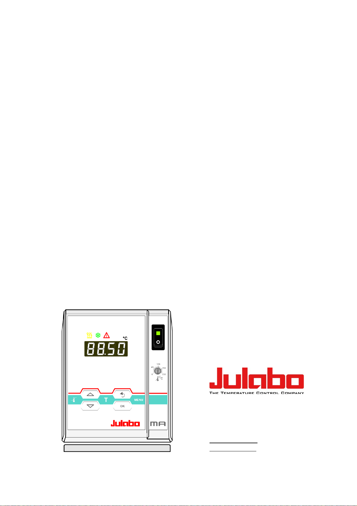
Page 1
English
Operating Manual
Heating Immersion Circulator
MA
1.951.0332-V2 06/13
JULABO GmbH
77960 Seelbach / Germany
Tel. +49 (0) 7823 / 51-0
Fax +49 (0) 7823 / 24 91
info@julabo.de
www.julabo.de
19510332-V2.doc 12.07.13
Page 2

Operating manual
Congratulations!
You have made an excellent choice.
JULABO thanks you for the trust you have placed in us.
This operating manual has been designed to help you gain an understanding of the operation
and possible applications of our circulators. For optimal utilization of all functions, we
recommend that you thoroughly study this manual prior to beginning operation.
The JULABO Quality Management System
Temperature control devices for research and industry are developed,
produced, and distributed according to the requirements of ISO 9001
and ISO 14001. Certificate Registration No. 01 100044846
Unpacking and inspecting
Unpack the circulator and accessories and inspect them for possible transport damage.
Damage should be reported to the responsible carrier, railway, or postal authority, and a
damage report should be requested. These instructions must be followed fully for us to
guarantee our full support of your claim for protecting against loss from concealed damage.
The form required for filing such a claim will be provided by the carrier.
Printed in Germany Changes without prior notification reserved
Important: keep operating manual for future use
2
Page 3

MA
TABLE OF CONTENTS
Operating manual .......................................................................................................... 5
1. Intended use .......................................................................................................... 5
1.1. Description ......................................................................................................... 5
2. Operator responsibility – Safety recommendations ............................................... 6
2.1. Disposal .............................................................................................................. 8
2.2. EC Conformity .................................................................................................... 9
2.3. Warranty conditions ............................................................................................ 9
2.4. Technical specifications ................................................................................... 10
Operating instructions .................................................................................................. 12
3. Safety notes for the user ...................................................................................... 12
3.1. Explanation of safety notes .............................................................................. 12
3.2. Explanation of other notes ............................................................................... 12
3.3. Safety recommendations .................................................................................. 12
4. Operating controls and functional elements ......................................................... 15
4.1. Circulator .......................................................................................................... 15
5. Preparations ......................................................................................................... 17
5.1. Installation ........................................................................................................ 17
5.2. Bath fluids ......................................................................................................... 18
5.3. Temperature application to external systems .................................................. 19
5.3.1. Pump set .................................................................................................. 19
5.3.2. Tubing ...................................................................................................... 20
5.4. Countercooling ................................................................................................. 21
6. Operating procedures .......................................................................................... 22
6.1. Power connection ............................................................................................. 22
6.2. Switching on / Start – Stop ............................................................................... 22
6.2.1. Switching on the circulator ....................................................................... 22
7. Setting of temperatures ............................................................................ 23
7.1. 1-setpoint mode / Direct setting of temperatures ............................................. 23
7.2. Using the pre-setting in the menu ........................................................ 23
8.
Safety installations, warning functions ..................................................... 25
8.1. Excess temperature protection ........................................................................ 25
3
Page 4

Operating manual
8.1.1. Early warning system, low level protection .............................................. 26
8.2. Switch-over from warning to shutdown function .............................................. 27
8.3. Over and Sub temperature warning function ................................................... 28
9. Menu functions ......................................................................................... 29
9.1. MENU PUMP – Setting of pump pressure ....................................................... 30
9.2. MENU Configuration ........................................................................................ 31
9.2.1. Configuration of the mode of the key ........................................... 32
9.2.2. Remote control: activate – deactivate ...................................................... 32
9.2.3. Automatic / non-automatic start mode ..................................................... 32
9.2.4. Reset - Factory setting ............................................................................. 33
9.3. MENU Control parameters – Xp, Tv, Tn .......................................................... 33
9.4. MENU SERIAL - BAUDRATE, PARITY, HANDSHAKE .................................. 35
9.5. MENU ATC - Absolut Temperature Calibration ............................................... 36
9.5.1. ATC STATUS - YES / NO ........................................................................ 38
9.5.2. ATC - TYPE: 1 -/ 2 -/ 3 POINT ................................................................. 38
9.5.3. Example: 3-point calibration for internal control ...................................... 39
9.6. MENU LIMITS .................................................................................................. 41
10. Troubleshooting guide / error messages ............................................................. 42
11. Electrical connections .......................................................................................... 44
12. Remote control ..................................................................................................... 45
12.1. Setup for remote control .............................................................................. 45
12.2. Communication with a PC or a superordinated data system ....................... 45
12.3. List of commands ......................................................................................... 46
12.4. Status messages ......................................................................................... 47
12.5. Error messages ............................................................................................ 47
13. JULABO Service – Online remote diagnosis ....................................................... 49
14. Cleaning / repairing the unit ................................................................................. 50
4
Page 5
MA
Operating manual
1. Intended use
JULABO circulators have been designed to control the temperature of specific fluids in a bath
tank.
JULABO circulators are not suitable for direct temperature control of foods,
semi-luxury foods and tobacco, or pharmaceutical and medical products.
Direct temperature control means unprotected contact of the object with the
bath medium (bath fluid).
1.1. Description
The circulators are operated via the splash-proof keypad. The implemented
microprocessor technology allows to set and to store different values that
can be indicated on the MULTI-DISPLAY (LED). Three menu keys facilitate
adjusting setpoints, warning and safety functions and menu functions.
PID2
ATC
RS232
SMART
PUMP
3
The PID temperature control adapts the heat supplied to the thermal
requirements of the bath.
Absolute Temperature Calibration (ATC3) provides a high temperature
stability in the bath. With the 3-point calibration an offset is adjusted at three
temperatures to ensure an accurate temperature pattern at the selected spot
in the bath over the full temperature range.
Electrical connections:
The serial interface RS232 allows modern process technology without
additional interface.
Alarm output for external alarm message or control of JULABO refrigerating
baths or solenoid valve (cooling water).
The excess temperature protection conforming to IEC 61010-2-010 is a
safety installation independent from the control circuit. This protection can be
indicated and set on the MULTI-DISPLAY (LED).
The early warning system for low level signals that bath fluid needs to be
refilled before the low level protection conforming to IEC 61010-2-010
causes a complete shut-down of the main functional elements.
The pump capacity (electronically adjustable via the motor speed) enables to
adapt to varying conditions for internal and external temperature
applications.
The circulator conforms to the relevant requirements specified by European
guidelines.
5
Page 6

Operator responsibility – Safety recommendations
2. Operator responsibility – Safety recommendations
The products of JULABO ensure safe operation when installed, operated, and maintained
according to common safety regulations. This section explains the potential dangers that may
arise when operating the circulator and also specifies the most important safety precautions to
preclude these dangers as far as possible.
The operator is responsible for the qualification of the personnel operating the units.
The personnel operating the units should be regularly instructed about the dangers
involved with their job activities as well as measures to avert these dangers.
Make sure all persons tasked with operating, installing, and maintaining the unit have read
and understand the safety information and operating instructions.
When using hazardous materials or materials that could become hazardous, the circulator
may be operated only by persons who are absolutely familiar with these materials and the
circulator. These persons must be fully aware of possible risks.
If you have any questions concerning the operation of your unit or the information in this
manual, please contact us!
Contact
JULABO GmbH
Eisenbahnstraße 45
77960 Seelbach / Germany
Tel. +49 (0) 7823 / 51-0
Fax +49 (0) 7823 / 24 91
info@julabo.de
www.julabo.de
Safety instructions for the operator:
You have received a product designed for industrial use. Nevertheless, avoid strikes to the
housing, vibrations, damage to the operating-element panel (keypad, display), and
contamination.
Make sure the product is checked for proper condition regularly (depending on the
conditions of use). Regularly check (at least every 2 years) the proper condition of the
mandatory, warning, prohibition and safety labels.
Make sure that the mains power supply has low impedance to avoid any negative effects
on instruments being operated on the same mains.
This unit is designed for operation in a controlled electromagnetic environment. This
means that transmitting devices (e.g., cellular phones) should not be used in the
immediate vicinity.
Magnetic radiation may affect other devices with components sensitive to magnetic fields
(e.g., monitors). We recommend maintaining a minimum distance of 1 m.
Permissible ambient temperature: max. 40 °C, min. 5 °C.
Permissible relative humidity: 50% (40 °C).
Do not store the unit in an aggressive atmosphere.
Protect the unit from contamination.
Do not expose the unit to sunlight.
6
Page 7
MA
Appropriate operation
Only qualified personnel is authorized to perform configuration, installation, maintenance and
repairs of the circulator.
Routine operation can also be carried out by untrained personnel who should however be
instructed by trained personnel.
Use:
The bath can be filled with flammable materials. Fire hazard!
There might be chemical dangers depending on the bath medium used.
Observe all warnings for the used materials (bath fluids) and the respective instructions
(safety data sheets).
Insufficient ventilation may result in the formation of explosive mixtures. Only use the unit in
well ventilated areas.
Only use recommended materials (bath fluids). Only use non-acid and non corroding
materials.
When using hazardous materials or materials that could become hazardous, the operator
must affix the enclosed safety labels (1 + 2) to the front of the unit so they are highly visible:
1
2
or
2
Particular care and attention is necessary because of the wide operating range.
There are thermal dangers: Burn, scald, hot steam, hot parts and surfaces that can be
touched.
Observe the instructions in the manuals for instruments of a different make that you connect to
the circulator, particularly the respective safety recommendations. Also observe the pin
assignment of plugs and technical specifications of the products.
Warning label W00: Colors: yellow, black
Danger area. Attention! Observe instructions.
(operating manual, safety data sheet)
Mandatory label M018: Colors: blue, white
Carefully read the user information prior to beginning operation.
Scope: EU
Semi S1-0701 Table A1-2 #9
Carefully read the user information prior to beginning operation.
Scope: USA, NAFTA
Warning label W26: Colors: yellow, black
Hot surface warning.
(The label is put on by JULABO)
7
Page 8

Operator responsibility – Safety recommendations
2.1. Disposal
The circulator contains a back-up battery that supplies voltage to memory chips when the unit
is switched off. Do not dispose of the battery with household waste!
Depending on battery regulations in your country, you might be obliged to give back used or
defect batteries to gathering places.
The product may be used with oil as bath fluid. These oils fully or partially consist of mineral oil
or synthetic oil. For disposal, observe the instructions in the safety data sheets.
Valid in EU countries
See the current official journal of the European Union – WEEE directive.
Directive of the European Parliament and of the Council on waste electrical
and electronic equipment (WEEE).
This directive requires electrical and electronic equipment marked with a
crossed-out trash can to be disposed of separately in an environmentally
friendly manner.
Contact an authorized waste management company in your country.
Disposal with household waste (unsorted waste) or similar collections of
municipal waste is not permitted!
8
Page 9

MA
2.2. EC Conformity
The products described in the operating instructions conform to the
requirements of the following European guidelines:
Directive of the European Parliament and of the Council on the
approximation of the laws of the Member States relating to machinery.
EMC guideline with respect to legal harmonization of the member countries
concerning electromagnetic compatibility.
JULABO GmbH
Eisenbahnstr. 45
77960 Seelbach / Germany
2.3. Warranty conditions
JULABO GmbH warrants its products against defects in material or in workmanship, when
used under appropriate conditions and in accordance with appropriate operating instructions
for a period of ONE YEAR.
Extension of the warranty period – free of charge
With the ‘1PLUS warranty’ the user receives a free of charge extension to the warranty of up
to 24 months, limited to a maximum of 10 000 working hours.
To apply for this extended warranty the user must register the unit on the JULABO web site
www.julabo.de, indicating the serial no. The extended warranty will apply from the date of
JULABO GmbH’s original invoice.
JULABO GmbH reserves the right to decide the validity of any warranty claim. In case of faults
arising either due to faulty materials or workmanship, parts will be repaired or replaced free of
charge, or a new replacement unit will be supplied.
Any other compensation claims are excluded from this guarantee.
9
Page 10

Operator responsibility – Safety recommendations
2.4. Technical specifications
Heating Immersion Circulator MA
Working temperature range
Temperature stability
Overall dimensions (WxDxH) cm 13x15x33
Usable bath depth cm from 8 to 14.5
Weight kg 4.0
All measurements have been carried out at: rated voltage and frequency
operating temperature: 70 °C ambient temperature: 20 °C bath fluid: water
Technical changes without prior notification reserved.
°C 20 ... 200
°C ±0,01
Mains power connection
208V - 230V; 50Hz - 60Hz
Current draw (at 208V) A 8
Current draw (at 230V) A 9
Mains power connection
100V - 115V; 50Hz - 60 Hz
Current draw (at 100V) A 8
Current draw (at 115V) A 9
MA
Temperature selection digital
via keypad indication on MULTI-DISPLAY(LED)
remote control via personal computer indication on monitor
Temperature indication MULTI-DISPLAY (LED)
Resolution (-9.99 …. +99.99 = 0.01) °C 0.01 / 0.1
Absolute Temperature Calibration °C ±3
Temperature control PID
V; Hz
V; Hz
187 - 253; 50 - 60 (perm. range)
90 - 127; 50 - 60 (perm. range)
Heater wattage (at 230 V) kW 2,0
Heater wattage (at 115V) kW 1,0
Electronically adj. pump capacity stages 1 ... 4
Flow rate max.at 0 bar l/min 11 ... 16
Pressure max. max. at 0 l bar 0.23 ... 0.45
Electrical connections:
External alarm device Vdc/mA 24-0 / max. 25
Computer interface RS232
Ambient temperature °C 5 ... 40
10
Page 11

Safety installations according to IEC 61010-2-010:
Excess temperature protection adjustable from 0 °C ... 230 °C
Low liquid level protection float switch
Classification according to DIN 12876-1 class III
Supplementary safety installations
Early warning system for low level float switch
High temperature warning function optical + audible (in intervals)
Low temperature warning function optical + audible (in intervals)
Supervision of working sensor plausibility control
Reciprocal sensor monitoring between
working and safety sensors difference >35 K
Alarm message optical + audible (permanent)
MA
Warning message optical + audible (in intervals)
Environmental conditions according to IEC 61 010-1:
Use only indoor.
Altitude up to 2000 m - normal zero.
Ambient temperature: +5 ... +40 °C
Air humidity:
Max. rel. humidity 80 % for temperatures up to +31 °C,
linear decrease down to 50 % relative humidity at a temperature of +40 °C
Max. mains fluctuations of ±10 % are permissible.
Protection class according to IEC 60 529 IP21
The unit corresponds to Class I
Overvoltage category II
Pollution degree 2
Caution:
The unit is not for use in explosive environment
Standards for interference resistance according to EN 61326-1
This unit is an ISM device classified in Group 1 (using high frequency for internal purposes)
Class A (industrial and commercial range).
11
Page 12
Operating instructions
Operating instructions
3. Safety notes for the user
3.1. Explanation of safety notes
In addition to the safety warnings listed, warnings are posted throughout the
operating manual. These warnings are designated by an exclamation mark
inside an equilateral triangle. “Warning of a dangerous situation (Attention!
Please follow the documentation).”
The danger is classified using a signal word.
Read and follow these important instructions for averting dangers.
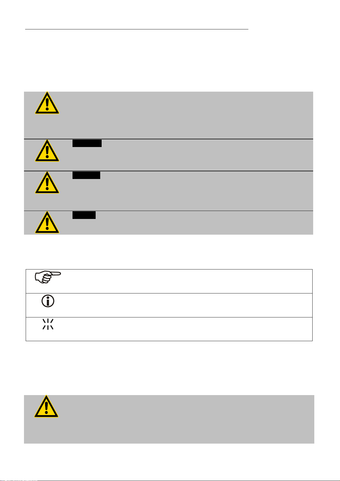
Warning:
Describes a possibly highly dangerous situation. If these instructions are not
followed, serious injury and danger to life could result.
Caution:
Describes a possibly dangerous situation. If this is not avoided, slight or minor
injuries could result. A warning of possible property damage may also be
contained in the text.
Notice:
Describes a possibly harmful situation. If this is not avoided, the product or
anything in its surroundings can be damaged.
3.2. Explanation of other notes
Note!
Draws attention to something special.
3.3. Safety recommendations
Follow the safety instructions to avoid personal injury and property damage.
Important!
Indicates usage tips and other useful information.
This icon is used in the operating instructions to indicate flashing values or
parameters which have to be set or confirmed.
Also, the valid safety instructions for workplaces must be followed.
Only connect the unit to a power socket with an earthing contact (PE –
protective earth)!
The power supply plug serves as a safe disconnecting device from the line
and must always be easily accessible.
Place the unit on an even surface on a base made of nonflammable
material.
12
Page 13

MA
Do not stay in the area below the unit.
Make sure you read and understand all instructions and safety precautions
listed in this manual before installing or operating your unit.
Set the excess temperature safety installation at least 25 °C below the fire
point of the bath fluid.
Observe the limited working temperature range when using plastic bath
tanks.
Never operate the unit without bath fluid in the bath.
Pay attention to the thermal expansion of bath oil during heating to avoid
overflowing of the fluid.
Prevent water from entering the hot bath oil.
Do not drain the bath fluid while it is hot!
Check the temperature of the bath fluid prior to draining (e.g., by switching
the unit on for a short moment).
Use suitable connecting tubing.
Avoid sharp bends in the tubing, and maintain a sufficient distance from
surrounding walls.
Make sure that the tubing is securely attached.
Regularly check the tubing for material defects (e.g., for cracks).
Never operate damaged or leaking units.
Always turn off the unit and disconnect the mains cable from the power
source before performing any service or maintenance procedures, or before
moving the unit.
Always turn off the unit and disconnect the mains cable from the power
source before cleaning the unit.
Always empty the bath before moving the unit.
Transport the unit with care.
Sudden jolts or drops may cause damage in the interior of the unit.
Observe all warning labels.
Never remove warning labels.
Never operate units with damaged mains power cables.
Repairs are to be carried out only by qualified service personnel.
Some parts of the bath tank and the pump connections may become
extremely hot during continuous operation. Therefore, exercise particular
caution when touching these parts.
Caution:
The temperature controlling i.e. of fluids in a reactor constitutes normal
circulator practice.
We do not know which substances are contained within these vessels.
Many substances are:
inflammable, easily ignited or explosive
hazardous to health
environmentally unsafe
i.e.: dangerous
13
Page 14

Safety notes for the user
The user alone is responsible for the handling of these substances!
The following questions shall help to recognize possible dangers and to reduce
the risks to a minimum.
Are all tubes and electrical cables connected and installed?
Note:
sharp edges, hot surfaces in operation, moving machine parts, etc.
Do dangerous steams or gases arise when heating?
Is an exhaust needed when working?
What to do when a dangerous substance was spilled on or in the unit?
Before starting to work, obtain information concerning the substance and
determine the method of decontamination.
Notice: Check the safety installations at least twice a year!
Excess temperature protection according to IEC 61010-2-010.
With a screwdriver turn back the adjustable excess temperature protection
until the shut-down point (actual temperature).
Low level protection according to IEC 61010-2-010.
To check the function of the float, it can be manually lowered with a
screwdriver for example.
14
Page 15
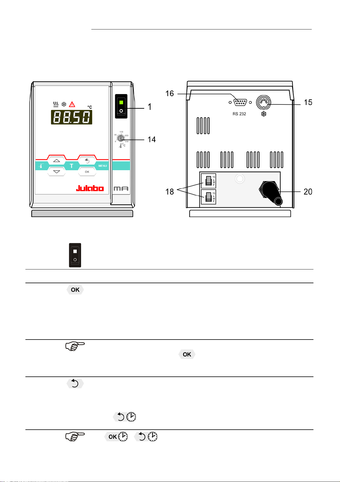
4. Operating controls and functional elements
4.1. Circulator
Front view Rear view
MA
1
2
Mains power switch, illuminated
Navigation keys
1. Key: >OK< Start / Stop (pump / heater )
2. >OK< in the menu Menu item / select submenu for setting
Save set value
Save selected parameter
A beep signals the end of setting
After the actions Start, Stop and change from VFD Display to
standard display the key
The above graph “front side” shows an example for standard display.
is locked for a short time.
3
1. Key: >Return< Stop (pump / heater )
2. >Return< in the menu one menu level down
Correction function for parameters or values (prior to OK)
immediately back to standard display
- icon for „keep key pressed down“.
15
Page 16

Operating controls and functional elements
4
1. Key: >Up / Down <temperature – increase/decrease setpoint
Push key quickly for single steps,
Keep key pressed for fast change.
2. >Up/Down< in the menu selection of menu items / parameters
5
6
7
10
11
12
Menu keys
Key: start the menu > warning and safety values<
Key: start the menu >temperature setpoints<
Key: display of MENU structure
MULTI-DISPLAY (LED) temperature indication, menu indication
Control indicator –Heating
Control indicator – Cooling (without function)
Navigation aids
Flashing segments show the position
within the structure of the menu.
Item „P“ flashes simultaneously in the
submenu.
13
14
15
16
18
20
RS232
Control indicator – Alarm
Adjustable excess temperature protection according to IEC 610102-010
Socket: control cable of JULABO refrigerated circulator
or output for alarm messages
Interface RS232: remote control via personal computer
Mains circuit breakers (resettable) 15 A
Mains power cable with plug
16
Page 17

5. Preparations
5.1. Installation
Caution:
Securely fix the immersion circulator. The heater may not be in contact with the
wall of the bath tank. Keep a distance of at least 15 mm.
Units not adequately fixed may drop into the bath tank.
Danger of electric shock!
First pull out the power plug to disconnect the unit from the power supply net.
Then take the immersion circulator out of the bath tank.
Make a service technician check the instrument before it is used again.
MA
Place the unit on an even surface on a pad made of non-
flammable material.
The heating immersion circulator is mounted using a bath
attachment clamp (21) designed for bath wall thicknesses
up to 26 mm.
Use the two sleeves (22) supplied with the unit to reduce
the immersion depth from 165 mm to 145 mm (see
drawing).
22
21
For use with glass vessels an upright stand rod,
available as optional accessory (order no. 8 970 022)
may be attached.
17
Page 18

Preparations
5.2. Bath fluids
Caution:
Carefully read the safety data sheet of the bath fluid used, particularly with
regard to the fire point!
If a bath fluid with a fire point of 65 °C is used, only supervised operation is
possible.
Water: The quality of water depends on local conditions.
Due to the high concentration of lime, hard water is not suitable for
temperature control because it leads to calcification in the bath.
Ferrous water can cause corrosion - even on stainless steel.
Chloric water can cause pitting corrosion.
Distilled and deionized water is unsuitable. Their special properties cause
corrosion in the bath, even in stainless steel.
Recommended bath fluids:
Bath fluid Temperature range
soft/decalcified water 5 °C to 80 °C
JULABO bath fluids
JULABO
Description
Thermal
G
Thermal
M
Thermal
HS
Order Number 10 liters 8 940 124 8 940 100 8 940 102
5 liters 8 940 125 8 940 101 8 940 103
Temperature range °C -30 ... 80 40 ... 170 20 ...250
Flash point °C -- 284 270
Fire point °C -- 306 >360
Color light yellow clear light brown
JULABO
Description
Thermal
H10
Thermal
H20S
Thermal
H200
Order Number 10 liters 8 940 114 8 940 108 8 940 134
5 liters 8 940 115 8 940 109 8 940 135
Temperature range °C -20 ... 180 0 ... 220 60 ...200
Flash point °C 190 230 292
Fire point °C 216 274 334
Color clear light brown clear
See website for list of recommended bath fluids.
2
ATTENTION: The maximum permissible viscosity is 50 mm
/s
18
Page 19
Caution:
Fire or other dangers when using bath fluids that are not recommended:
Please contact JULABO before using other than recommended bath fluids.
Use only nonacidic and noncorrosive bath fluids.
JULABO assumes no liability for damage caused by the selection of an
unsuitable bath liquid.
Unsuitable bath fluids are fluids which, e.g.,
are highly viscous
(much higher than recommended at the respective working temperature)
have a low viscosity and have creep characteristics
have corrosive characteristics or
tend to crack.
No liability for use of other bath fluids!
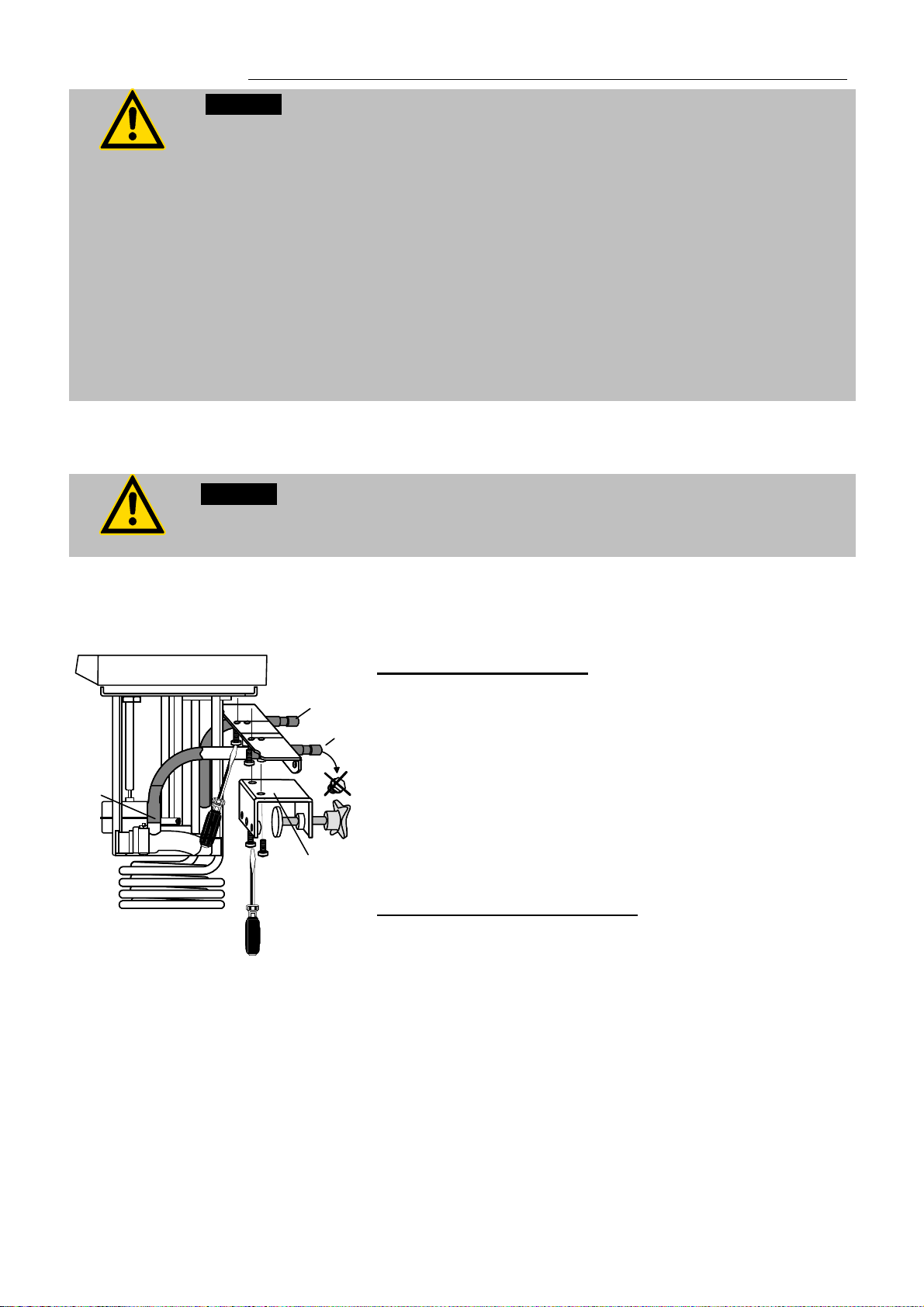
5.3. Temperature application to external systems
Caution: Securely attach all tubing to prevent slipping.
MA
If the circulator is operated without external system, close the pump connector
(24a) with the cap nut.
5.3.1. Pump set
23
24b
24a
21
The circulator is used for temperature application to
external, closed systems (loop circuit).
Mounting the pump set:
Remove the bath attachment clamp (21).
Screw the pump set to the circulator, and then fix the
bath attachment clamp to the pump set.
Slide the short piece of tubing supplied with the pump
set onto the short pump nozzle and the pump
connector (23).
Thus the total immersion depth is reduced to 145 mm.
Adjusting the pump for external bath circulation see
example D - MENU PUMP.
Connecting an external system:
Unscrew the collar nuts from the pump connector
(24a).
Slide the tubing onto the pump connector for feed
(24a) and return flow (24b) and secure with hose
clamps
Accessories
Order No. Description
8 970 140 Pump set
19
Page 20
Preparations
®
5.3.2. Tubing
Recommended tubing:
Order No. Length Temperature range
8 930 008 1 m CR
tubing 8 mm inner dia. -20 °C to 120 °C
8 930 010 1 m CR® tubing 10 mm inner dia. -20 °C to 120 °C
8 930 108 1 m Viton tubing 8 mm inner dia. -50 °C to 200 °C
8 930 110 1 m Viton tubing 10 mm inner dia. -50 °C to 200 °C
8 930 410 1 m Insulation for tubing 8 mm or
-50 °C to 100 °C
10 mm inner dia.
8 970 480 2 tubing clamps. size 1, tubing 8 mm inner dia.
8 970 481 2 tubing clamps. size 2, tubing 10 or 12 mm inner dia.
8 930 209 0.5 m
8 930 210 1.0 m
Metal tubing, triple insulated,
M16x1 *
-100 °C to +350 °C
8 930 211 1.5 m
8 930 214 3.0 m
8 930 220 0.5 m
Metal tubing, insulated, M16x1 * -50 °C to +200 °C
8 930 221 1.0 m
8 930 222 1.5 m
8 930 223 3.0 m
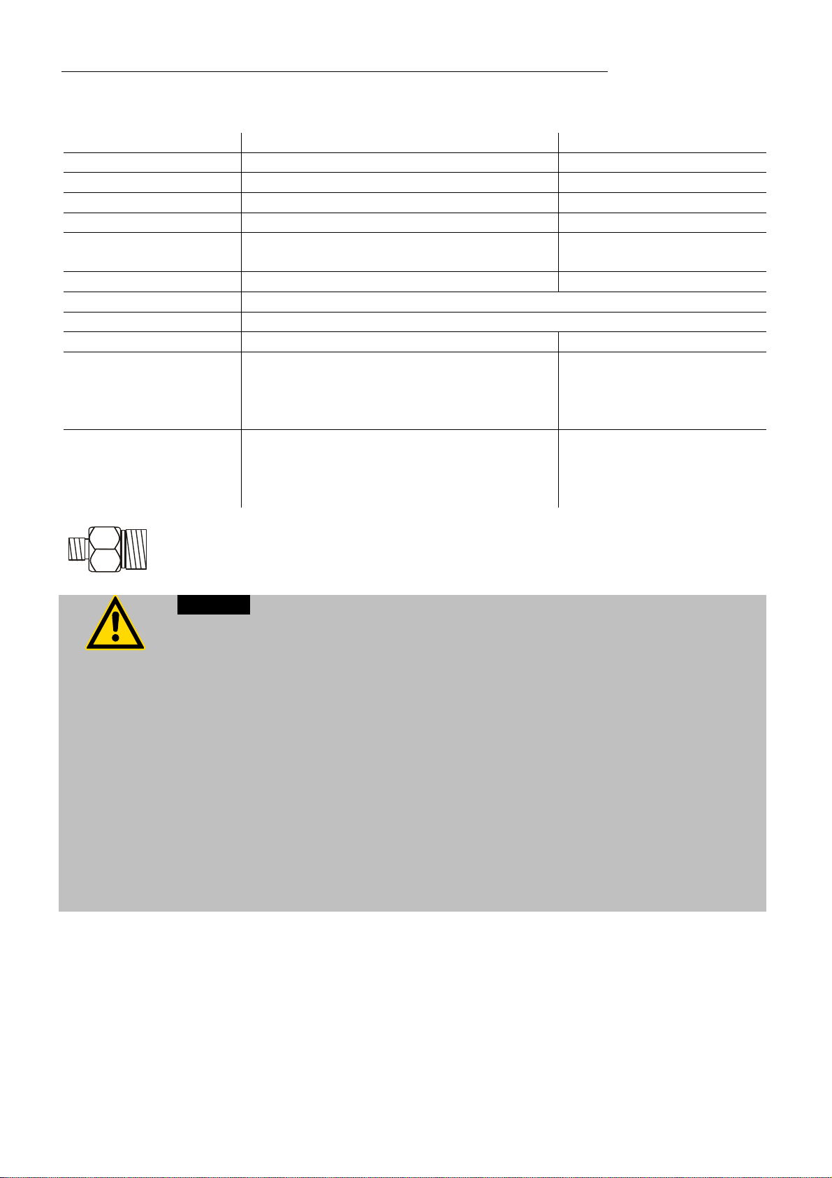
*) Adapter for metal tubing M10x1 on M16x1 Order No. 8 970 444
Warning: Tubing:
At high working temperatures the tubing used for temperature application and
cooling water supply represents a danger source.
A damaged tubing line may cause hot bath fluid to be pumped out within a
short time.
This may result in:
Burning of skin
Difficulties in breathing due to hot atmosphere
Safety recommendations
Employ suitable connecting tubing.
Make sure that the tubing is securely attached.
Avoid sharp bends in the tubing, and maintain a sufficient distance from
surrounding walls.
Regularly check the tubing for material defects (e.g. for cracks).
Preventive maintenance: Replace the tubing from time to time.
20
Page 21

5.4. Countercooling
Notice:
Securely attach all tubing to prevent slipping.
Observe the laws and regulations of the water distribution company valid in the
location where the unit is operated.
25b
25a
21
For applications near the ambient temperature, the
cooling coil (order no. 8 970 105) must be connected to
the water mains.
Mounting the cooling coil:
Remove the bath attachment clamp (21).
Screw the cooling coil to the circulator, and then fix
the bath attachment clamp to the cooling coil.
Thus the total immersion depth is reduced to 145 mm.
Using tubing, connect the cooling coil (25a) to the tap
water supply, and lead the tap water in a sink through the
return connector (25b).
A specific water flow rate of 45 ml/minute is sufficient
to compensate for the characteristic temperature.
MA
21
Page 22

Operating procedures
6. Operating procedures
6.1. Power connection
Caution:
Only connect the unit to a power socket with earthing contact (PE –
6.2. Switching on / Start – Stop
protective earth)!
The power supply plug serves as safe disconnecting device from the line
and must be always easily accessible.
Never operate equipment with damaged mains power cables.
Regularly check the mains power cables for material defects (e.g. for
cracks).
We disclaim all liability for damage caused by incorrect line voltages!
Check to make sure that the line voltage matches the supply
voltage specified on the identification plate.
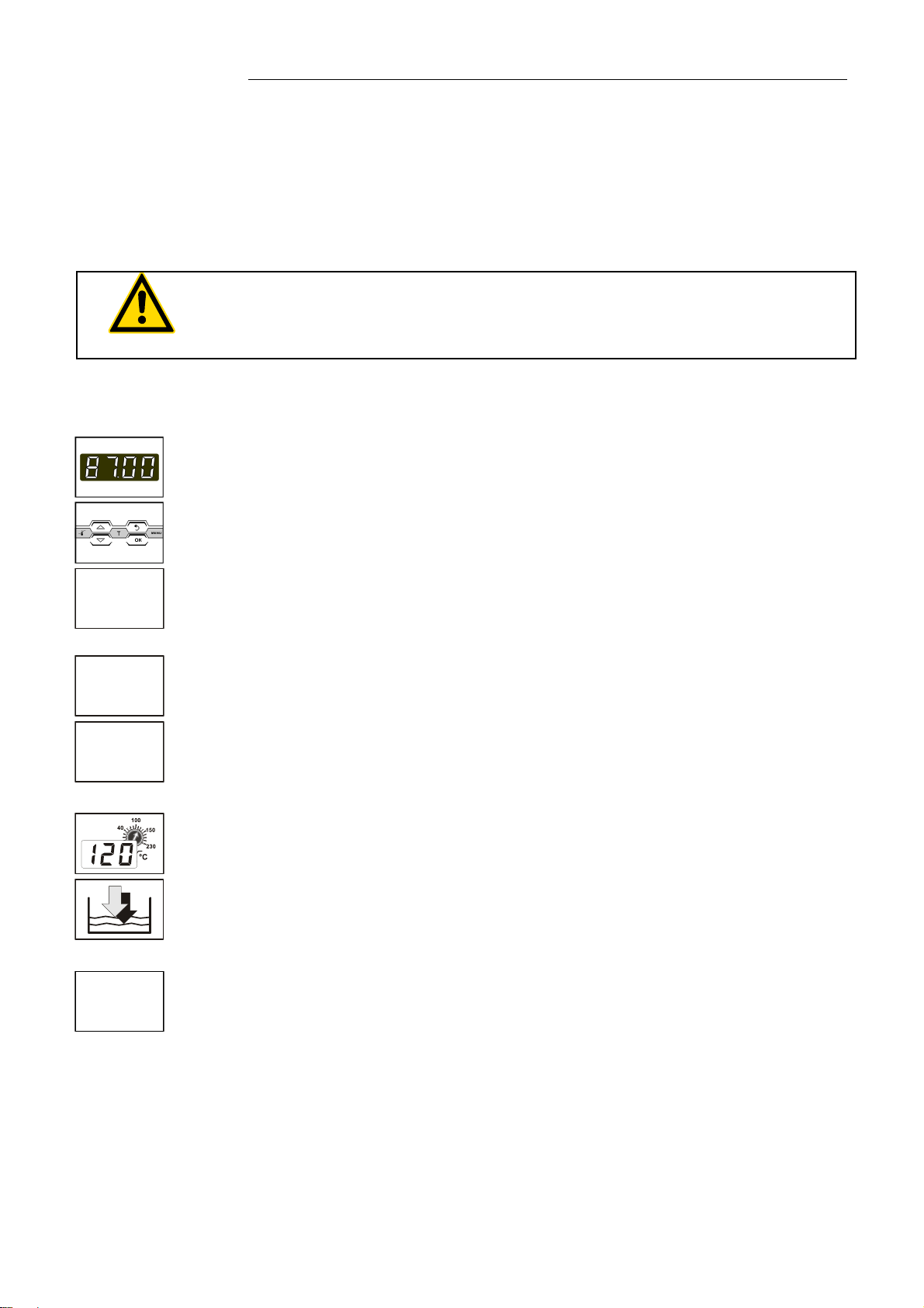
6.2.1. Switching on the circulator
Switching on:
Turn on the mains power switch (1).
The unit performs a self-test. All segments of the 4-digit MULTI-
DISPLAY (LED) and all indicator lights will illuminate.
Then the software version (example: tt 2, V1.12, b004))
appears. The display „OFF“ or „R OFF“ indicates the unit is
ready to operate.
The circulator enters the operating mode activated before
switching the circulator off:
keypad control mode (manual operation)
or
remote control mode (operation via personal computer).
Start:
Press
The actual bath temperature is displayed on the LEDDISPLAY. The circulating pump starts with a slight delay.
Stop:
key.
22
Press
or
Keep
The LED -DISPLAY indicates the message "OFF".
key.
key pressed.
Page 23
7. Setting of temperatures
MA
The function of the key is configurable.
1. If the key is pressed, normally only one adjustable working
temperature is displayed (factory setting).
2. Using the Menu Configuration which is started by pressing the
key a menu with three pre-set setpoints can be
assigned to the key.
Press key if a value is to be retained.
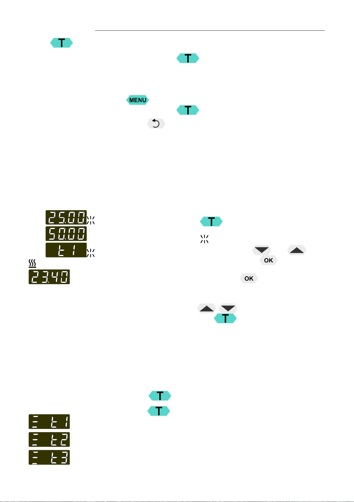
7.1. 1-setpoint mode / Direct setting of temperatures
The circulator uses the setpoint of t1 or t2 or t3 for temperature
control.
The indicated setpoint temperature can be changed directly any
time.
Example: change 25.00 °C to 50.00 °C
1. By pressing the key the circulator switches to the
active >Setpoint< in the example on the left > t1 25.00°C<.
The integer digits flash (example: <25>).
2. Change the value by pressing the keys and to
50.00 °C and confirm by pressing the key .
The decimal digits flash and can be adjusted if desired.
Confirm once more by pressing the key.
The end of the adjustment is signalled by the flashing message
>t1<
If the „Up / Down“ keys are pressed immediately
instead of pressing the key
temperature setting.
The circulator uses the new working temperature value for
temperature control.
The temperatures can be set in start or stop mode.
7.2. Using the pre-setting in the menu
Factory setting:
25 °C
37 °C
70 °C
Press the
3 different working temperatures can be adjusted. Their values are
freely adjustable with the working temperature range.
Important:
Prior to the adjustment switch-over to the 3-temperature mode has
to be effected in the menu configuration.
key to call up the menu for temperature setting.
this is called direct
23
Page 24

Setting of temperatures
Refer to page 32 for switch-over to 3-temperature-mode
CFG = CONFIGURATION
3SP = 3 SETPOINT
Setting of working temperature in the menu
1. Press the key
2. Select SETPOINT >t 1< or >t 2< or >t 3< using the key
or .
3. Confirm by pressing the key.
The circulator uses the new working temperature value for
temperature control.
Example: setting / adjustment of of pre-settings of "t 3"
1. Press the key. The parameter >tx< flashes.
2. Select the setpoint >t3< by pressing or .
3. Keep the key pressed until the integer digits flash .
(example: <70>)
4. Change the value by pressing and to 85.00 °C and
confirm by pressing the key.
The decimal digits flash
Confirm once more by pressing the
Example on the left: SETPOINT >t3< / 85.00.
The end of the adjustment is signaled by the flashing message
>t3<
. The value >tx< flashes
and can be adjusted if desired.
key.
24
If the active setpoint (SETPNT) is changed, the new value is
immediately used for the control of the working temperature.
The heater control indicator flashes.
If the other two setpoints (not activated for control) are changed
the MENU has to be left by pressing the key after
the decimal digits have been confirmed
Notice: Refer to chapter
9.6. MENU LIMITS
Page 25

MA
8.
8.1. Excess temperature protection
Safety installations, warning functions
Check the safety installations at least twice a year! Refer to ( page 14)
Settings for the excess temperature protection > tSA<
and for the warning functions for high > tHi< and low > tLo<
temperature are made in a menu which is called up by pressing the
key .
Menu item > Aty (ALARM-TYPE)< allows choosing between a
warning and an alarm cut-off for the menu items > tHi < and >tLo<.
This excess temperature protection is independent of the control
circuit. When activated heater and circulating pump are
completely shut down.
The alarm is indicated by optical and audible signals (continuous
tone) and the error message "ALARM-CODE 14" appears on the
MULTI-DISPLAY (LED)
Setting range: 20 °C ... 230 °C
Rough setting can be effected by using the temperature scale.
Exact setting:
1. Press the key to display menu > tSA <.
2. Press the key and the set shutdown value is indicated.
Set the new shutdown value within 30 seconds using a
screwdriver. The value is indicated on the MULTI-DISPLAY (LED)
Example: >tSA< / 100 °C
Recommendation:
Set the excess temperature protection at 5 °C to 10 °C above the
working temperature setpoint.
Warning:
The excess temperature protection must be set at least 25 °C below the fire
point of the bath fluid used!
In case of wrong setting there is a fire hazard!
We disclaim all liability for damage caused by wrong settings!
25
Page 26

Safety installations, warning functions
8.1.1. Early warning system, low level protection
Warning:
For refill always use the same bath fluid type that is already in the bath.
Bath oils must not contain any water contaminants and should be pre-heated
to the actual bath temperature!
Explosion hazard at higher temperatures!
This low level protection is independent of the control
circuit and is divided in two sections.
(patented)
1. Switch in stage 1 recognizes a defined
fluid level .
An audible warning (interval tone) sounds and on
the MULTI-DISPLAY (LED) the message "E 40"
appears.
Refill bath fluid!
2. Switch in stage 2 recognizes a low fluid level .
If stage 2 of the low level protection device
(according to IEC 61010-2-010) is triggered, a
complete shutdown of the heater and circulating
pump is effected.
A continuous alarm tone sounds and a message
>CODE 01< appears on the MULTI-DISPLAY
(LED).
26
Turn off the unit with the mains switch, refill bath fluid and turn
the unit on again!
3. Float
4. Circulating pump
5. Heater
Page 27

8.2. Switch-over from warning to shutdown function
If a shutdown of functional elements (e.g. heater, circulating pump) is
Factory setting:
>0 = WARNING<
required when the limit values are exceeded or undercut the
circulator can be changed over from warning function >WARNING<
to shutdown function >ALARM<.
1. Press the key .
2. Select the menu >Aty (ALARM-TYPE)< by pressing the
key.
3. Press the key and the set parameter will flash .
(Example: 0)
4. Change the parameter by pressing the key and confirm by
pressing the key.
or
press the key if the parameter is to retained.
MA
Setting >0 = WARNING<
A mere warning function with optical and audible warning signal
(interval tone) A message appears on the MULTI-DISPLAY
(LED):
or
OVERTMP SUBTEMP
Setting >1 = ALARM<
Temperature limit with shutdown of heater and circulating pump.
An audible alarm sounds (continuous tone) and a message
appears on the MULTI-DISPLAY (LED):
or
OVERTMP SUBTEMP
27
Page 28
Safety installations, warning functions
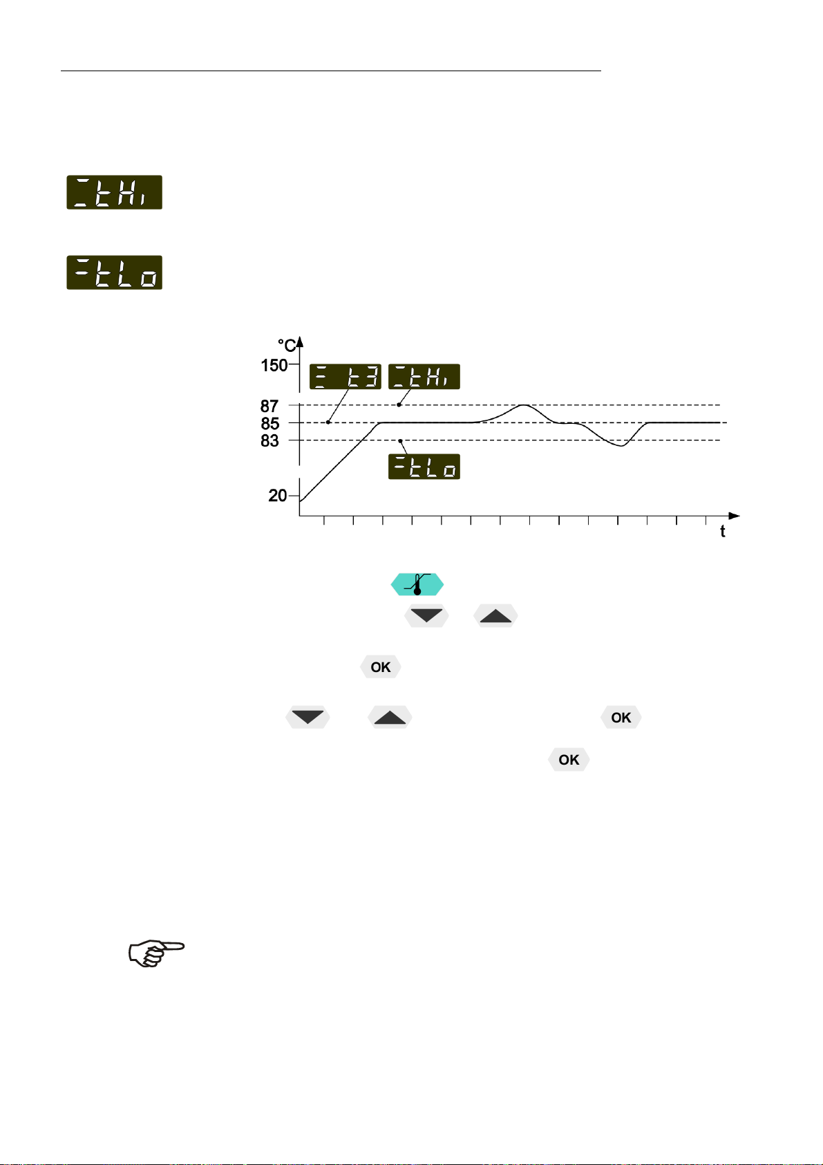
8.3. Over and Sub temperature warning function
Factory settings:
Over temperature
t High 205 °C
Sub temperature
t Low -55 °C
If the observance of a working temperature value >t 3< has to be
supervised for a sensitive temperature application, then set over
and sub temperature warning values. In the example below the
setpoint >t 3< 85 °C is surrounded by the values >t High< 87 °C
and >t Low< 83 °C. The electronics immediately register if the
actual temperature breaches one of the set limit values. The
resulting reaction is defined in the menu item >Aty (ALARMTYPE)< refer to (page 27).
1. Press the key .
2. By pressing the or
or > tLow <.
3. Press the key. The integer digits flash.
4. Change the values to 87. °C and/or 83. °C by pressing the
and
The decimal digits flash and can be adjusted if desired.
Confirm once more by pressing the
See above examples.
key and confirm with the key.
key select the menu > tHigh <
key.
The warning functions are only activated if the actual bath
temperature remains within the set limit values for 3 seconds
after switch-on.
Recommendation:
Set the over temperature warning value > t High < 5 °C to 10 °C
above the working temperature setpoint.
28
Set the sub temperature warning value > t Low < 5 °C to 10 °C
below the working temperature setpoint.
Page 29

9. Menu functions
MA
Menu level 1
The term „Menu functions“ refers to settings such as
>Pu< - Electronically adjustable pump capacity page 30
>CFG< - Configuration of the unit page 31
>3SP< - 3-setpoint mode
>rt< - REMOTE – on / off (remote control via RS232)
>Aut < – AUTOSTART on / off
>rST< - RESET – factory settings
PID Control parameters page 33
Control parameter XP
Control parameter Tn
Control parameter Tv
Adjustable interface parameters page 35
ATC
>br< - Baudrate
>Pty< - Parity
>HS< - Handshake
ATC - Absolute Temperature Calibration page 35
>Sta< - ATC status
>tyP< - Type
>1. point<, >2. point < or >3. point < calibration
2 values per calibration point
ttx = Defined temperature value of the calibration point.
This value is automatically stored with >Ctx< and can be
indicated for control purposes.
Ctx = The „Calibration value“ is determined with a
temperature measuring device and stored under menu
item > Ctx <.
Limitations of temperature page 41
>SPHigh< - Maximum setpoint
>SPLow< - Minimum setpoint
29
Page 30

Menu functions
9.1. MENU PUMP – Setting of pump pressure
The capacity of the circulating pump is set by adjusting the motor
speed
Factory setting:
stage 1
Settings: stage 1 ... 4
Flow rate: 11 ... 16 l/m
Pump pressure: 0,22 ... 0,45 bar
1. Press the key. Menu >Pu< is indicated.
2. Press the
3. Change the parameter by pressing
pressing the key.
or
Press the key if the parameter is to be retained.
The pump flow is pre-adjusted in the factory and can be
modified to suit user requirements.
Using a screwdriver turn the screw (1) anti-clockwise by
360 °.
Using flat pliers turn the marking of the slide (2) to the
desired position.
Tighten the screw.
key. The set parameter flashes (example: > 2<)
or and confirm by
30
Examples:
Internal applications in the bath
A 100 % internal bath circulation
(for large bath tanks)
B Reduced internal bath circulation
(for smooth surface of bath fluid)
External/internal applications
C 40 % external discharge,
60 % internal circulation
(for large bath tanks)
D 80 % external discharge,
20 % internal circulation
(for small bath tanks)
Page 31

9.2. MENU Configuration
MA
Menu level 1
Level 2 Parameter level
CFG = MENU CONFIGURATION
A RESET can be effected only in the > < mode.
Switch off circulator by pressing the key and call up the menu
CONFIGURATION.
or
or
Press the key if a parameter is to be
retained. Correction function for parameters and
values (prior to OK).
>3SP< - Switch on and off the 3-setpoint mode
The parameter flashes, set by pressing
+
>YES< - This function can be used by pressing
the key. (refer to page 23)
>rt< - Switch on and off remote control
The parameter flashes, set by pressing
+
or
For remote control refer to 44
Connect RS232 with PC
>Aut< - Switch on and off autostart
The parameter flashes, set by pressing
+
AUTOSTART on
AUTOSTART off.
See WARNING page 33
>rSt< (RESET) - Use this to reset all values to
factory setting.
Return to factory settings by pressing
During the message – init - all parameters are
reset to factory settings.
31
Page 32
Menu functions
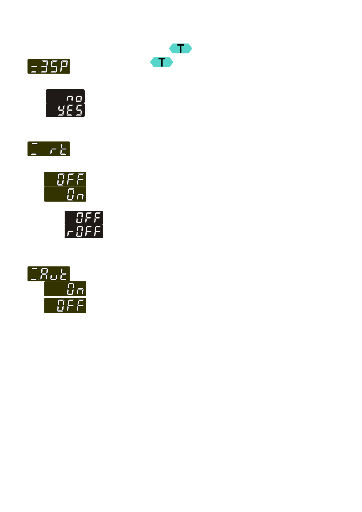
9.2.1. Configuration of the mode of the key
Pressing the key normally indicated only one working
Factory setting: no
9.2.2. Remote control: activate – deactivate
Factory setting: OFF
temperature which can be individually adjusted.
The configuration opens a menu with 3 setpoints which can be pre-
set.
>no< 1-temperature mode
>YES< 3-temperature mode
The circulator is to be prepared for remote control by a personal
computer via the serial interface RS232: Set the menu item
>>rt< = remote< from >OFF< to >On<.
9.2.3. Automatic / non-automatic start mode
>OFF< No remote control via RS232
>On< Remote control via RS232
The display changes from
keypad control mode (manual operation) to
remote control mode (operation via personal computer).
AUTOSTART on.
AUTOSTART off.
Notice:
The circulator has been configured and delivered by JULABO in
accordance with the NAMUR recommendations. This means for the
start mode that the unit must enter a safe operating status after a
power failure. This safe operating status is indicated by the message
„OFF“ or „r OFF“ on the MULTI-DISPLAY (LED).
A complete, all-pole shutdown of the main functional elements such
as heater and pump motor is effected.
The values set on the circulator remain saved and the unit is
restarted by pressing the start/stop key in manual control.
In remote control mode the values need to be resent by the PC via
the interface.
If such a safety standard is not required, the NAMUR
recommendations can be bypassed with the AUTOSTART function
thus allowing a direct start of the circulator by pressing the mains
switch or using a timer.
32
Page 33
Warning:
For supervised or unsupervised operation with the “AUTOSTART“ function
avoid any hazardous situation to persons or property
Take care to fully observe the safety and warning functions of the circulator.
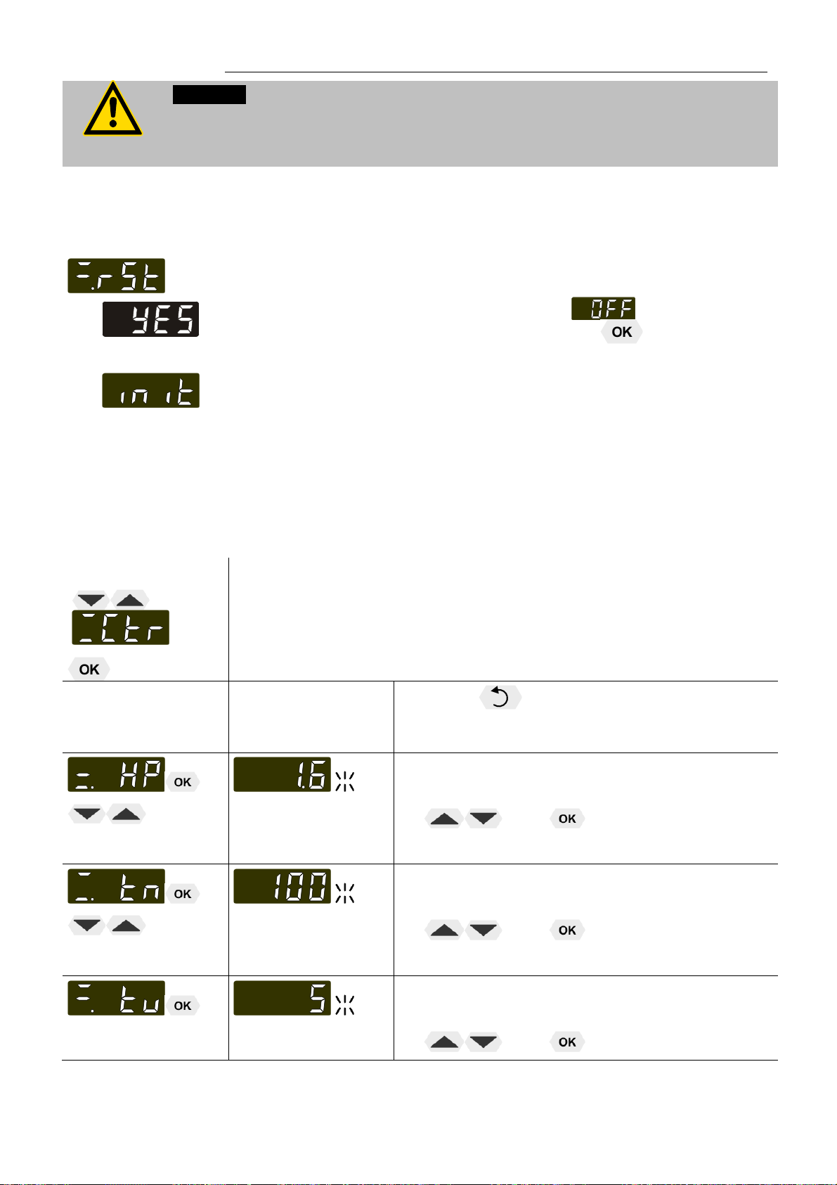
9.2.4. Reset - Factory setting
>YES< resets all values to factory setting.
A >rSt< RESET can be effected in the > < mode only.
Switch off the circulator by pressing the key and call up the
menu CONFIGURATION.
During the message – init - all parameters are reset to factory
settings
MA
9.3. MENU Control parameters – Xp, Tv, Tn
Menu level 1
Level 2 Parameter level
In most cases the control parameters preset in the factory are adequate
for achieving an optimum temperature sequence.
The control parameters allow adjustment to special control processes..
Press the
retained. Correction function for parameters or
values (prior to OK)
Proportional range >Xp<
0.1 … 99.9
3 … 9999
The parameter flashes, switch by pressing
Reset time >Tn< (Integral component)
The parameter flashes, switch by pressing
key if a parameter is to be
and
and
Lead time >Tv< (Differential component)
0 … 999
The parameter flashes, switch by pressing
and
33
Page 34
Menu functions
Setting range:
0.1 ... 99.9
Setting range:
3 ...9999
Setting range:
0 ... 999
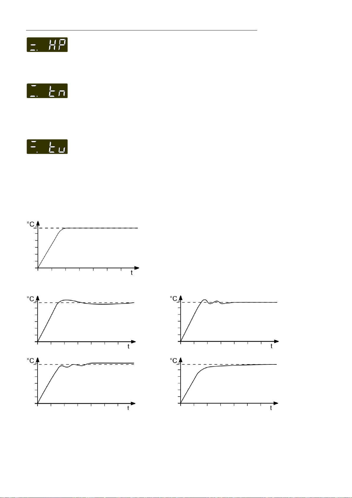
Optimum setting
Proportional range >Xp<
The proportional range is the range below the setpoint in which the
control circuit reduces the heating capacity from 100% to 0 %
Reset time >Tn< (Integral component)
Compensation of the remaining control deviation due to proportional
regulation. An insufficient reset time may cause instabilities. Excessive
reset times will result in unnecessary prolongation of compensation of
the control difference.
Lead time >Tv< (Differential component)
The differential component reduces the transient time. An insufficient
lead time will prolong the time required for compensation of disturbance
effects and cause high overshooting during run-up. An excessive lead
time could cause instabilities (oscillations)
Optimization instructions for the PID control parameters
Control parameters XP-, TN-, TV- INTERNAL as
well as
-EXTERNAL
The heat-up curve reveals possible faulty
settings of the control parameter.
Xp too high or Tv too high
Inappropriate settings may produce the following heat-up curves:
Xp too low
Tv/Tn too high or Xp too high
Tv/Tn too low
34
Page 35
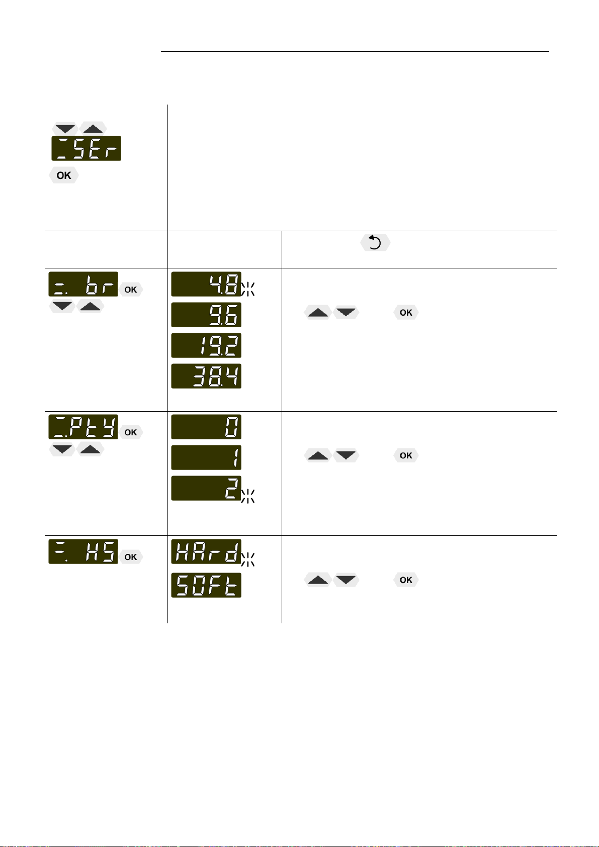
9.4. MENU SERIAL - BAUDRATE, PARITY, HANDSHAKE
MA
Menu level 1
Level 2 Parameter level
For communication between circulator and a PC or a superordinated
process control system the interface parameters of both units must be
identical.
Factory settings:
4800 Baud
even
hardware handshake
Press the key if a parameter is to be
retained.
>br< - BAUDRATE
The parameter flashes, switch by pressing
and
4.8 = 4800 Baud
9.6 = 9600 Baud
19.2 = 19200 Baud
38.4 = 38400 Baud
>PtY< - PARITY
The parameter flashes, switch by pressing
and
0 no: Datenbits = 8; Stopbits = 1
1 odd: Datenbits = 7; Stopbits = 1
2 even: Datenbits = 7; Stopbits = 1
>HS< - HANDSHAKE
The parameter flashes, switch by pressing
and
Xon/Xoff-protocol (Software handshake)
Protocol RTS/CTS (Hardware handshake)
35
Page 36

Menu functions
°
9.5. MENU ATC - Absolut Temperature Calibration
ATC serves to compensate a temperature difference that might occur
between circulator and a defined measuring point in the bath tank
because of physical properties.
Example:
1-point calibration
°C
Principle:
For ATC calibration, in steady state the bath temperature at the
location of the temperature sensor (CT) is determined at the
respective adjusted working temperature. This value is then set on
the circulator in the menu >ATCalibration< under menu item >Ctx<.
This can be a 1-point, 2-point or 3-point calibration.
T 1
T
3-point calibration
°C
T 1
T
TT 1 = Original curve
Menu level 1
M B (INT) T
°C
C
TT
M = Temperature measuring instrument with temperature sensor
B = Bath tank (INTernal or EXTernal)
T = circulator
°C
CT = Temperature on measuring point
TT = Temperature on circulator
Level 2 Parameter level
Press the key if parameter is to be
retained. Correction function for parameters or
values (prior to OK).
>StA< - ATC Status
or
The parameter flashes, switch by pressing
and
>NO< Carry out an ATC calibration
>YES< return to standard operation after
calibration.
36
Page 37

MA
>tYP< - ATC TYPE
The parameter flashes, switch by pressing
and
A >1-point<, >2-point< or >3-point<
calibration can be carried out.
The value > tt1< is only indicated
In addition the measured temperature value
>Ct 1< is saved during the next step.
Integer digits flash, set by pressing
+
Decimal digits flash, set by pressing
+
If only a 1-point calibration is carried out, the following menu items
are not indicated anymore
The value > tt2< is only indicated
In addition the measured temperature value
>Ct 2< is saved during the next step.
Integer digits flash, set by pressing
+
Decimal digits flash, set by pressing
+
If only a 2-point calibration is carried out, the following menu items
are not indicated anymore
The value > tt3< is only indicated
In addition the measured temperature value
>Ct 3< is saved during the next step.
Integer digits flash, set by pressing
+
Decimal digits flash, set by pressing
+
37
Page 38

Menu functions
9.5.1. ATC STATUS - YES / NO
9.5.2. ATC - TYPE: 1 -/ 2 -/ 3 POINT
In the second submenu the ATC function for the temperature sensor
selected above is activated >YES< or deactivated >NO<.
>YES< (factory setting) The controller of the circulator uses the
original curve of the temperature sensor or the new curve
measured during the ATC calibration.
Important: Set to >NO< during the calibration process
>NO< An ATC calibration is to be carried out.
Important: Set to >YES< after calibration.
In the > ATC STATUS < >YES< the ATC calibration always affects
the current working temperature; also the one set via interface.
A >1-point<, >2-point< or >3-point< calibration can be carried out.
First geometrically define the location for calibration (measuring point
CT), then determine the temperature values of the calibration points.
The type of calibrations also determines the number of the following
pairs of values indicated on the MULTI-DISPLAY (LED)..
Pairs of values:
tt X: Circulator temperature 1 or 2 or 3 (actual value TT )
The actual temperature of the bath is simultaneously saved with
the “calibration value“ >CALVAL< and can be indicated for control
purposes (value does not flash).
Ct X: Calibration temperature 1 or 2 or 3 (actual value CT )
The „calibration value“ is determined with a temperature measuring
device and saved under menu item >CALVAL<.
(value flashes )
38
Page 39

MA
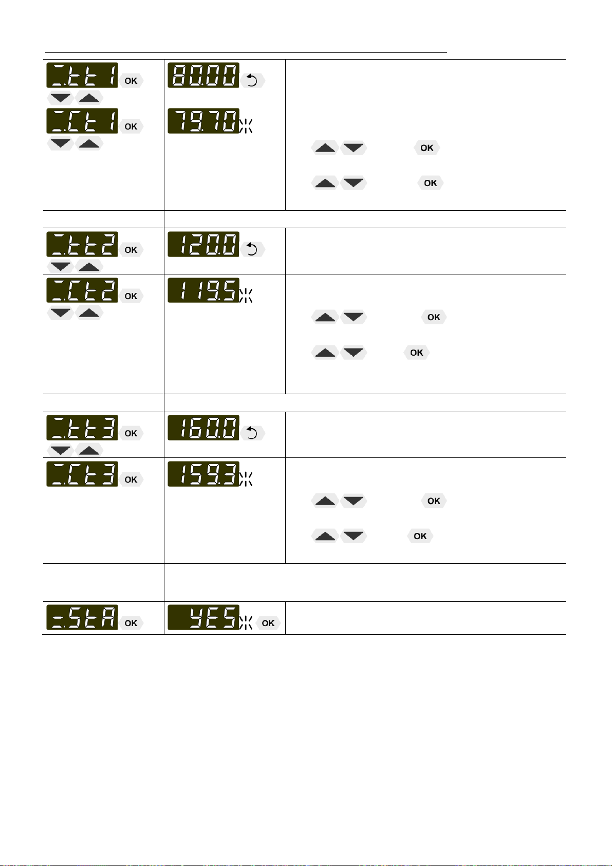
9.5.3. Example: 3-point calibration for internal control
In the temperature range from 80 °C to 160 °C the calibration curve of
the temperature sensor (TT) is to be adjusted to the actual temperatures
at measuring point (CT).
80.00 °C
120.00 °C
160.00 °C
1. Set working temperature setpoint :
Refer to „Direct temperature setting “ page 23
1. By pressing the key or the circulator switches to the
active >SETPOINT< see example on the left: >t1 25.00°C<.
The integer digits flash (Example: <25>).
2. Change the value to 80.00 °C by pressing the keys and
and
confirm by pressing the key .
The decimal digits flash.
Confirm once more by pressing the key .
3. The bath is heated up.
Wait for approx. 5 minutes until the temperature is constant.
2. Reading of temperature measuring device
Read the value of measuring point CT on the device and enter under
menu item >Ct X< by using the keypad.
>Ct 1< (79.70 °C)
>Ct 2< (119.5 °C)
>Ct 3< (159.3 °C)
Menu level 1
Level 2 Parameter level
3. Calibration
Press the key if parameter is to be retained. Correction
function for parameters or values (prior to OK).
Setting is required only for the first calibration point.
An ATC calibration is to be carried out.
Set to >no<
The parameter flashes, switch by pressing
and .
The parameter flashes, switch by pressing
and .
A >3-point< calibration is carried out.
39
Page 40
Menu functions
The value >tt1< is only indicated
Return to 1. Set working temperature value: 120.00 °C
Setting >Ct 1< by using the keys.
Integer digits flash, set by pressing
(79) +
Decimal digits flash, set by pressing
(70) +
The first of 3 points is calibrated.
The value >tt2< is only indicated
Setting >Ct 2< by using the keys.
Integer digits flash, set by pressing
(119) +
Decimal digits flash, set by pressing
(5) +
The second of 3 points is calibrated.
Return to 1. Set working temperature value: 160.00 °C
The value >tt3< is only indicated
4. Return to standard operation
Setting >Ct 3< by using the keys.
Integer digits flash, set by pressing
(159) +
Decimal digits flash, set by pressing
(3) +
The 3-point calibration is completed
Set >YES< after calibration.
(Standard operation)
40
Page 41

9.6. MENU LIMITS
MA
Menu level 1
Level 2 Parameter level
Factory settings::
200 °C
(Setpiont High)
>Li< = LIMITS – limitation of operating temperature range
Maximum and minimum setpoint
Restriction of the adjustable temperature range.
The limitation of the operating temperature range effects the
temperature setting in the menu with the key
Only setting of working temperatures which lie within the
determined limits is possible
This applies to settings in the MENU ,
Press the key if parameter is to be retained.
Correction function for parameters or values (prior
to OK).
Integer digits flash, set by pressing
Decimal digits flash, set by pressing
Integer digits flash, set by pressing
Decimal digits flash, set by pressing
+
+
+
+
.
-50 °C
(Setpoint Low)
and for settings in the MENU
high temperature low temperature
The temperature values are automatically deferred into the limit
range.
Setting range: -50,0 °C ... +200,0 °C
(refer to page 23)
(refer to page 28)
41
Page 42
Troubleshooting guide / error messages
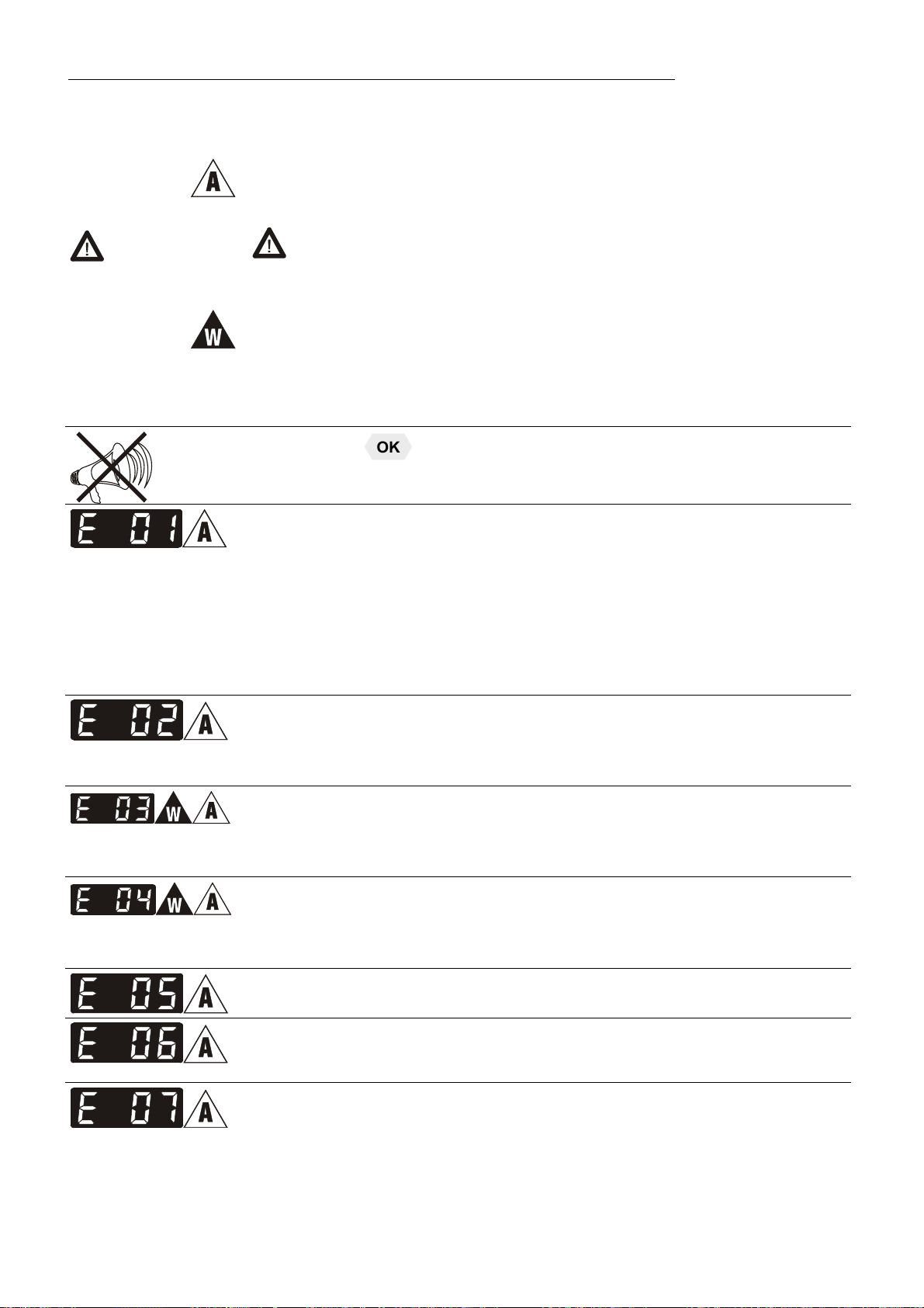
10. Troubleshooting guide / error messages
Alarm with complete shutdown:
If one of the following failures occur a complete, all-pole shutdown of the
heater and circulating pump is effected.
+
„ “ lights up and a continuous signal sounds.
The code for the cause of alarm is indicated on the MULTI-DISPLAY
(LED).
Warning without a complete shutdown of the unit
The MULTI-DISPLAY (LED) indicates the cause for the warning in form
of a code and an acoustic signal sounds in regular intervals.
These messages appear every 10 seconds.
Press the key
Low level alarm
The circulator is operated without or insufficient bath fluid.
Switch the unit off with the mains switch, refill bath fluid and switch on!
Tube breakage has occurred (insufficient filling level of bath fluid caused
by pumping-out)
Replace the tubing and refill bath liquid.
The float is defect (e.g. transport damage).
Repair by authorized JULABO service personnel.
to stop the signal
During the self-test after switch-on a short –circuit is detected between
pin 2 and pin 4 of the control line or the control line was disconnected
during operation.
Reconnect the control line or repair short-circuit.
Excess temperature warning
or
Excess temperature alarm
Type of warning: set to >0 = warning< or >1 = alarm<
Low temperature warning
or
Low temperature alarm.
Typ of warning: set to >0 = warning< or >1 = alarm<
Cable of working temperature sensor is disconnected or short-
circuited.
Defect of working or excess temperature protector.
Working temperature sensor and excess temperature protector report a
temperature difference of more than 35 K.
Other errors
Internal hardware error – call service
42
Page 43

MA
Error in A/D converter
Excess temperature protector defect.
The protection temperature is below the set working temperature
setpoint.
Set the protection temperature to a higher value.
The cable of the excess temperature protector has been disconnected or
short-circuited
The early warning system for low level reports a critical fluid level. Refill
bath fluid.
60
By quickly switching off and restarting the unit the alarm is
1545
4 s
30
15
A
M
P
cancelled.
If the error occurs once more after the restart, a remote diagnosis is
required.
„Configuration Error“
The configuration of the circulator does not correspond with its current
application.
Press the key for a non-recurring, automatic change of the
configuration.
In this case please call the JULABO Technical Service or an authorized
dealer.
Disturbances that are not indicated.
The electronic pump motor is overload-protected by an electronic current
limiter. If viscosity of the bath fluid is or becomes too high, the motor
stops running.
Mains circuit breakers (resettable) 15 A
43
Page 44

Electrical connections
9
5
11. Electrical connections
Notice:
Use shielded cables only. The shield of the connecting cable is electrically
connected to the plug housing.
The unit ensures safe operation if connecting cables with a maximum length of
3 m are used. The use of longer cables does not affect proper performance of
the unit, however external interferences may have a negative impact on safe
operation (e.g. cellular phones).
/ Control output
The connector may be used for control of JULABO refrigerated
2
4
13
5
1
6
RS232C
Accessories: Order No. Description
circulators or as output for alarm messages.
Circuit: Operation = relay powered
Alarm = relay not powered
Pin assignment:
Pin Signal
1 +24 V (I max. current 25 mA)
2 0 V
3 Alarm relay
4 Reserved - do not use!
5 Cooling pulse
RS232 serial interface
This port can be used to connect a computer with an RS232 cable
for remote control of the circulator.
Pin assignments RS232:
Pin 2 RxD Receive Data
Pin 3 TxD Transmit Data
Pin 5 0 V Signal GND
Pin 7 RTS Request to send
Pin 8 CTS Clear to send
Pin 1; 4; 6, 9 Reserved - do not use!
RS232 interface cable
Circulator (9-pol) PC (9-pol)
Pin 2 RxD Pin 3 TxD
Pin 3 TxD Pin 2 RxD
Pin 5 GND Pin 5 GND
Pin 7 RTS Pin 8 CTS
Pin 8 CTS Pin 7 RTS
8 980 073 RS232 interface cable 9-pol./9-pol. , 2,5 m
8 900 110 USB interface adapter cable
44
Page 45
9
5
12. Remote control
12.1. Setup for remote control
MA
1
6
RS232C
12.2. Communication with a PC or a superordinated data system
A transfer sequence consists of:
Check the interface parameters for both interfaces (on circulator
and PC) and make sure they match.
(Serial interface refer to page 35.)
In the menu >CFG< (Configuration) set the menu item >rt<
(Remote) to >ON< . (refer to page 32).
Connect both units with an interface cable.
Like all parameters which can be entered through the keypad,
interface parameters are stored in memory even after the circulator is
turned off.
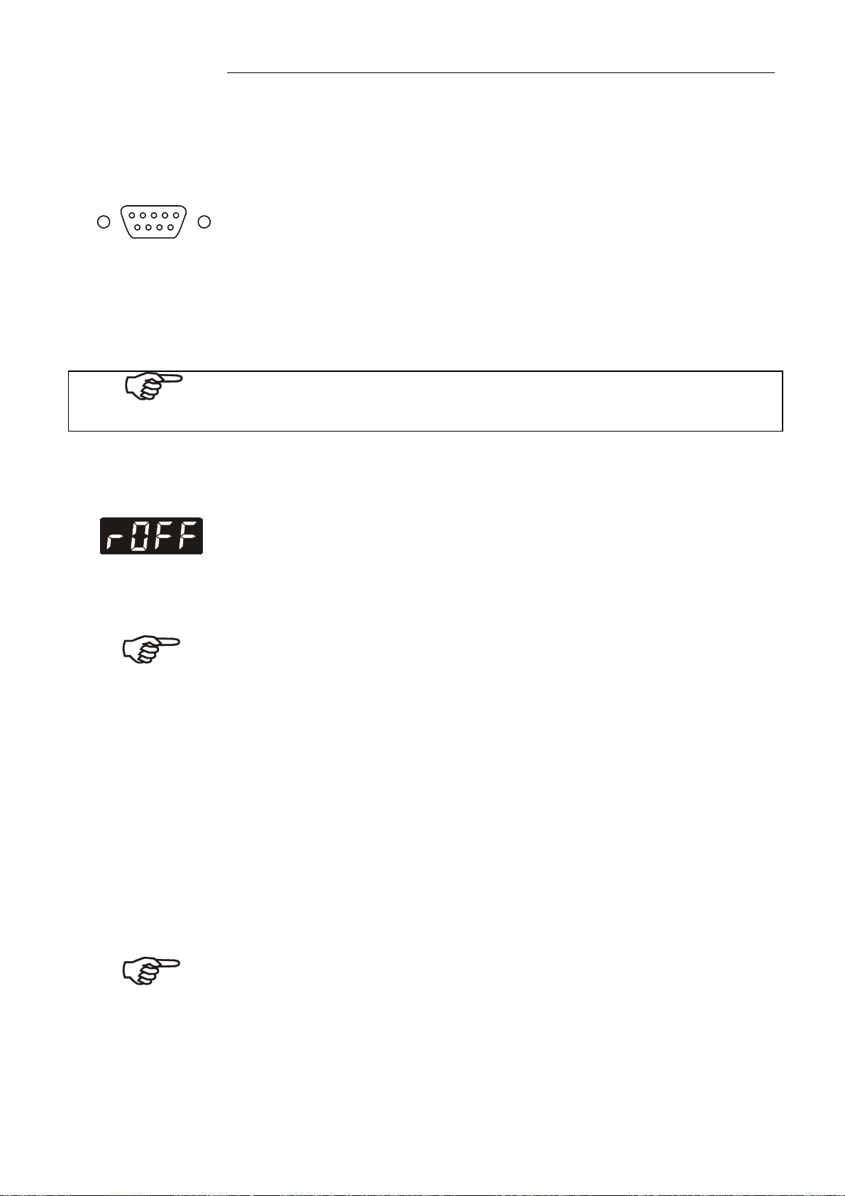
If the circulator is put into remote control mode via the configuration
level, the MULTI-DISPLAY (LED) will read „r OFF“ = REMOTE STOP.
The circulator is now operated via the computer.
In general, the computer (master) sends commands to the circulator
(slave). The circulator sends data (including error messages) only
when the computer sends a query.
In remote control mode, the start command and all values to be set
must be resent by the PC via the interface in case of a power
interruption.
AUTOSTART is not possible.
command
space (
; Hex: 20)
parameter (decimal separation with a period)
end of file (; Hex: 0D)
The commands are divided into in and out commands.
in commands: retrieve parameters
out commands: set parameters
The out commands are valid only in remote control mode.
Command to set the working temperature > t 1< to 55.5 °C
out_sp_00 55.5
Command to retrieve the working temperature > t 1<
in_sp_00
Response from the circulator: 55.5
45
Page 46

Remote control
12.3. List of commands
out commands: Setting parameters or temperature values.
Command Parameter Response of circulator
version None Number of software version (V X.xx)
status none Status message, error message (see page 47 )
out_mode_01 0 Use working temperature >t 1<
out_mode_01 1 Use working temperature >t 2<
out_mode_01 2 Use working temperature >t 3<
out_mode_05 0 Stop the unit = R –OFF-.
out_mode_05 1 Start the unit.
out_sp_00 xxx.xx Set working temperature. „t 1“
out_sp_01 xxx.xx Set working temperature. „t 2“
out_sp_02 xxx.xx Set working temperature. „t 3“
out_sp_03 xxx.xx Set high temperature warning limit „t High“
out_sp_04 xxx.xx Set low temperature warning limit „t Low“
out_sp_07 x Set the pump pressure stage. (1 ... 4)
out_par_06 xxx Xp control parameter of the internal controller.
out_par_07 xxx Tn control parameter of the internal controller.
out_par_08 xxx Tv control parameter of the internal controller.
in commands: Asking for parameters or temperature values to be displayed.
Command Parameter Response of circulator
in_pv_00 none Actual bath temperature.
in_pv_01 none Heating power being used (%).
in_pv_03 none Temperature value registered by the safety sensor.
in_pv_04 none Setpoint temperature („SafeTemp“) of the excess
temperature protection
in_sp_00 none Working temperature „t 1“
in_sp_01 none Working temperature „t 2“
in_sp_02 none Working temperature „t 3“
46
Page 47
Command Parameter Response of circulator
in_sp_03 none High temperature warning limit „t High“
in_sp_04 none Low temperature warning limit „t Low“
in_sp_07 none Pump pressure stage
in_par_01 none Te - Time constant of the external bath.
in_par_02 none Si - Internal slope
in_par_03 none Ti - Time constant of the internal bath.
in_par_06 none Xp control parameter of the internal controller.
in_par_07 none Tn control parameter of the internal controller.
in_par_08 none Tv control parameter of the internal controller.
in_mode_01 none Selected setpoint:
0 = Setpoint „t 1“
1 = Setpoint „t 2“
2 = Setpoint „t 3“
in_mode_05 none Circulator in Stop/Start condition:
0 = Stop
1 = Start
MA
12.4. Status messages
Status messages Description
00 MANUAL STOP
01 MANUAL START
02 REMOTE STOP
03 REMOTE START
12.5. Error messages
ERROR MESSAGES Description
-01 LOW LEVEL ALARM Low liquid level alarm.
-02 REFRIGERATOR ALARM Control cable of the refrigerated circulator or
-03 EXCESS TEMPERATURE WARNING High temperature warning.
-04 LOW TEMPERATURE WARNING Low temperature warning.
Circulator in „OFF“ state.
Circulator in keypad control mode.
Circulator in „r OFF“ state.
Circulator in remote control mode.
MVS solenoid valve controller short-circuited
or interrupted.
-05 WORKING SENSOR ALARM Working temperature sensor short-circuited or
interrupted.
47
Page 48

Remote control
ERROR MESSAGES Description
-06 SENSOR DIFFERENCE ALARM Sensor difference alarm.
Working temperature and safety sensors
report a temperature difference of more than
35 K.
-07 I2C-BUS ERROR Internal error when reading or writing the I2C
bus.
-08 INVALID COMMAND Invalid command.
-09 COMMAND NOT ALLOWED IN
CURRENT OPERATING MODE
-10 VALUE TOO SMALL Entered value too small.
-11 VALUE TOO LARGE Entered value too large.
-12 TEMPERATURE MEASUREMENT
ALARM
-13 WARNING : VALUE EXCEEDS
TEMPERATURE LIMITS
-14 EXCESS TEMPERATURE
PROTECTOR ALARM
-20 WARNING: CLEAN CONDENSOR OR
CHECK COOLING WATER CIRCUIT OF
REFRIGERATOR
-21 WARNING: COMPRESSOR STAGE 1
DOES NOT WORK
-22 WARNING: COMPRESSOR STAGE 2
DOES NOT WORK
-23 WARNING: HIGH TEMPERATURE
ON COMPRESSOR STAGE 1
-24 WARNING: HIGH TEMPERATURE
ON COMPRESSOR STAGE 2
-25 REFRIGERATOR WARNING Error in the refrigerating machine.
Invalid command in current operating mode.
Error in A/D converter.
Value lies outside the adjusted range for the
high and low temperature warning limits. But
value is stored.
Excess temperature protection alarm
Cooling of the condenser is affected.
Clean air-cooled condenser.
Check the flow rate and cooling water
temperature on water-cooled condenser.
Compressor stage 1 does not work.
Compressor stage 2 does not work.
Excess temperature on compressor stage 1.
Excess temperature on compressor stage 2.
-30 CONFIGURATION ERROR:
CONFIRM BY PRESSING <ENTER> ON
CIRCULATOR
-33 SAFETY SENSOR ALARM Excess temperature sensor short-circuited or
-40 NIVEAU LEVEL WARNUNG Low liquid level warning in the internal
48
The configuration of the circulator does not
conform to its present use.
Press to automatically perform a single
modification of the configuration.
interrupted.
reservoir.
Page 49

13. JULABO Service – Online remote diagnosis
MA
JULABO circulators of the HighTech series are equipped with
a black box. This box is implemented in the controller and
records all significant data for the last 30 minutes.
In case of a failure, this data can be read out from the unit by
using special software. This software is available as a free
download from www.julabo.de \ EasyBlackBox.
Installation is easy and is performed step by step.
Please observe the instructions.
Data read-out is possible in the conditions
“OFF”, “R OFF” or “ALARM”.
Connect the circulator to the computer using an interface
cable.
Start the EasyBlackBox program.
The program asks for the port used (COM1, ......) and the
baud rate of the unit.
You do not have this information on hand? Simply try it out!
The program continues to send the request until the correct
settings are made.
Data is read out and shown on the monitor
divided into the sections
>Einstellungen/Settings<,
>Alarmspeicher/Alarms stored<,
>Blackbox<
see example
After pressing >Speichern/Save<, a text file is
created. The program suggests a filename >C:\model description and barcode no.<.
Modifications are possible.
E-mail this file to service@julabo.de, JULABO's
service department. JULABO is thus able to
provide rapid support.
49
Page 50

Cleaning / repairing the unit
14. Cleaning / repairing the unit
Caution:
Always turn off the unit and disconnect the mains cable from the power
source before cleaning the unit.
Prevent humidity from entering into the circulator.
Electrical connections and any other work must be performed by qualified
personnel only.
Cleaning:
For cleaning the bath tank and the immersed parts of the
circulator, use low surface tension water (e.g., soap suds).
Clean the outside of the unit using a wet cloth and low surface
tension water.
The circulator is designed for continuous operation under normal
conditions. Periodic maintenance is not required.
The tank should be filled only with a bath fluid recommended by
JULABO. To avoid contamination, it is essential to change the
bath fluid from time to time.
Repairs
Before asking for a service technician or returning a JULABO
instrument for repair, please contact an authorized JULABO
service station.
When returning the unit:
Clean the unit in order to avoid any harm to the service
personnel.
Attach a short fault description.
During transport the unit has to stand upright. Mark the
packing correspondingly.
When returning a unit, take care of careful and adequate
packing.
JULABO is not responsible for damages that might occur from
insufficient packing.
JULABO reserves the right to carry out technical modifications
with repairs for providing improved performance of a unit.
50
 Loading...