

Page 1
Operating Manual
Programmable Controller
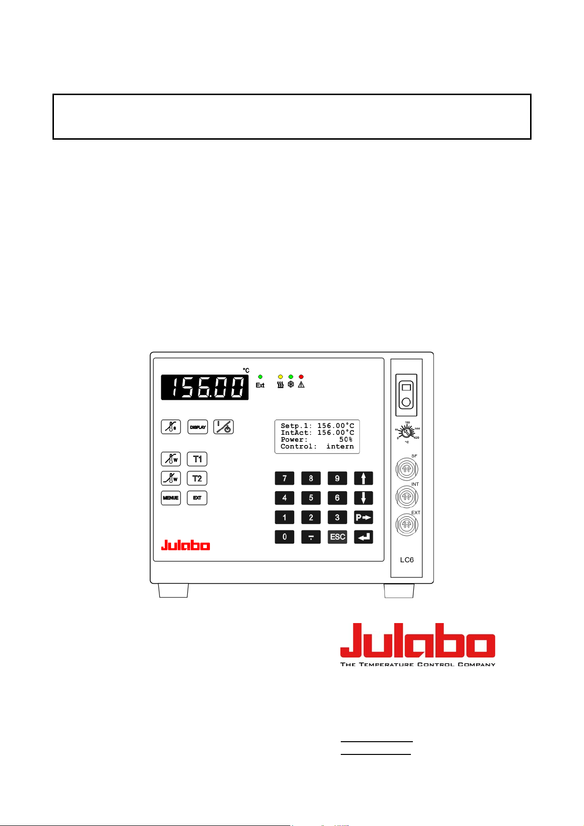
LC6
JULABO GmbH
77960 Seelbach / Germany
Tel. +49 (0) 7823 / 51-0
Fax +49 (0) 7823 / 24 91
1.951.5220-V2 06/13
19515220-V2.DOC 26.07.2013
info@julabo.de
www.julabo.de
Page 2

Congratulations!
You have made an excellent choice.
JULABO thanks you for the trust you have placed in us.
This operating manual has been designed to help you gain an understanding of the operation and
possible applications of our circulators. For optimal utilization of all functions, we recommend that
you thoroughly study this manual prior to beginning operation.
The JULABO Quality Management System
Temperature control devices for research and industry are developed,
produced, and distributed according to the requirements of ISO 9001 and
ISO 14001. Certificate Registration No. 01 100044846
Unpacking and inspecting
Unpack the circulator and accessories and inspect them for possible transport damage. Damage
should be reported to the responsible carrier, railway, or postal authority, and a damage report
should be requested. These instructions must be followed fully for us to guarantee our full support
of your claim for protecting against loss from concealed damage. The form required for filing such
a claim will be provided by the carrier.
Printed in Germany Changes without prior notification reserved
Important: keep operating manual for future use
2
Page 3

TABLE OF CONTENTS
Operating manual ............................................................................................................................. 5
1. Intended use .............................................................................................................................. 5
1.1. Description ......................................................................................................................... 5
2. Operator responsibility – Safety recommendations ................................................................... 5
2.1. Disposal ............................................................................................................................. 7
2.2. EC Conformity .................................................................................................................... 8
2.3. Warranty conditions............................................................................................................ 8
2.4. Technical specifications ..................................................................................................... 9
Operating instructions ..................................................................................................................... 11
3. Safety notes for the user .......................................................................................................... 11
3.1. Explanation of safety notes .............................................................................................. 11
3.2. Explanation of other notes................................................................................................ 11
3.3. Safety recommendations .................................................................................................. 11
4. Operating controls and functional elements ............................................................................. 13
5. Operating procedures .............................................................................................................. 15
5.1. Installation ........................................................................................................................ 15
5.2. Connecting a heating device ............................................................................................ 15
5.3. Connecting the temperature sensors ............................................................................... 16
5.4. Controlling an intermittent cooling water supply ............................................................... 16
5.5. Applications ...................................................................................................................... 17
6. Operating procedures .............................................................................................................. 19
6.1. Power connection ............................................................................................................. 19
6.2. Switching on / Selecting the language ............................................................................. 19
7. Manual operation ..................................................................................................................... 20
7.1. Start - Stop ....................................................................................................................... 20
7.2. Setting the temperatures .................................................................................................. 20
7.3. Warning functions ............................................................................................................ 21
7.4. Setting the safety temperature (with shutdown function) ................................................. 22
7.5. Internal / external control .................................................................................................. 23
8. Menu functions ......................................................................................................................... 24
8.1. Configuration .................................................................................................................... 25
8.2. Control parameters ........................................................................................................... 28
8.3. Start of a profile ................................................................................................................ 29
8.4. Integrated programmer ..................................................................................................... 32
3
Page 4

8.5. Analog inputs/outputs ....................................................................................................... 35
8.6. Limits ................................................................................................................................ 38
8.7. Interface ........................................................................................................................... 38
8.8. Sensors ............................................................................................................................ 39
9. Troubleshooting guide / Error messages ................................................................................. 40
10. Electrical connections .......................................................................................................... 41
11. Remote control ..................................................................................................................... 44
11.1. Setup for remote control ............................................................................................... 44
11.2. Communication with a PC or a superordinated data system ....................................... 45
11.3. List of commands ......................................................................................................... 46
11.4. Status messages / error messages .............................................................................. 49
12. Cleaning / repairing the unit ................................................................................................. 50
4
Page 5
Operating manual
1. Intended use
Fulfilling its principle task, reliable temperature control and measurement, the LC6 temperature
controller also implements safety and monitoring functions, particularly in the areas of chemical
research and quality control. The sophisticated capabilities of the unit allow wide application with
electrical heating devices such as
heating hoods, heating baths,
heating pads and bandages,
water and oil baths.
JULABO Temperature controllers are not suitable for direct temperature control
of foods, semi-luxury foods and tobacco, or pharmaceutical and medical
products. Direct temperature control means unprotected contact of the object
with the bath medium (bath fluid).
1.1. Description
Setting is rapid and simple using the keypad with its easy to learn symbols. Keypad is splashproof, easily cleaned and ergonomically designed.
The microprocessor technology allows four temperature values to be stored and indicated on the
DIALOG-DISPLAY (LCD): working temperatures T1 and T2, high and low temperature warning
limits.
The safety value for excess temperature protection, a safety installation independent from the
control circuit, is adjustable on the front with simultaneous indication on the MULTI-DISPLAY
(LED).
The RS232/RS485 port permits modern process engineering without additional interface, directly
on-line, from the circulator to your application equipment.
Besides the digital interface, additionally analog connectors are provided, such as for
Pt100 external sensor, analog programmer input, temperature recorder output and others.
2. Operator responsibility – Safety recommendations
The products of JULABO ensure safe operation when installed, operated, and maintained
according to common safety regulations. This section explains the potential dangers that may arise
when operating the circulator and also specifies the most important safety precautions to preclude
these dangers as far as possible.
The operator is responsible for the qualification of the personnel operating the units.
The personnel operating the units should be regularly instructed about the dangers involved
with their job activities as well as measures to avert these dangers.
Make sure all persons tasked with operating, installing, and maintaining the unit have read and
understand the safety information and operating instructions.
When using hazardous materials or materials that could become hazardous, the circulator
may be operated only by persons who are absolutely familiar with these materials and the
circulator. These persons must be fully aware of possible risks.
5
Page 6

Operator responsibility – Safety recommendations
If you have any questions concerning the operation of your unit or the information in this manual,
please contact us!
Contact:
Safety instructions for the operator:
You have received a product designed for industrial use. Nevertheless, avoid strikes to the
housing, vibrations, damage to the operating-element panel (keypad, display), and
contamination.
Make sure the product is checked for proper condition regularly (depending on the conditions
of use). Regularly check (at least every 2 years) the proper condition of the mandatory,
warning, prohibition and safety labels.
Make sure that the mains power supply has low impedance to avoid any negative effects on
instruments being operated on the same mains.
This unit is designed for operation in a controlled electromagnetic environment. This means
that transmitting devices (e.g., cellular phones) should not be used in the immediate vicinity.
Magnetic radiation may affect other devices with components sensitive to magnetic fields
(e.g., monitors). We recommend maintaining a minimum distance of 1 m.
Permissible ambient temperature: max. 40 °C, min. 5 °C.
Permissible relative humidity: 50% (40 °C).
Do not store the unit in an aggressive atmosphere.
Protect the unit from contamination.
Do not expose the unit to sunlight.
JULABO GmbH
Eisenbahnstraße 45
77960 Seelbach / Germany
Tel. +49 (0) 7823 / 51-0 info@julabo.de
Fax +49 (0) 7823 / 24 91 www.julabo.de
Appropriate operation
Only qualified personnel is authorized to perform configuration, installation, maintenance and
repairs of the unit.
Routine operation can also be carried out by untrained personnel who should however be
instructed by trained personnel.
Use:
The bath can be filled with flammable materials. Fire hazard!
There might be chemical dangers depending on the bath medium used.
Observe all warnings for the used materials (bath fluids) and the respective instructions (safety
data sheets).
Insufficient ventilation may result in the formation of explosive mixtures. Only use the unit in well
ventilated areas. The unit is not for use in explosive atmosphere.
Only use recommended materials (bath fluids). Only use non-acid and non corroding materials.
When using hazardous materials or materials that could become hazardous, the operator must
affix the enclosed safety labels (1 + 2) to the front of the unit so they are highly visible:
6
Page 7
1
2
or
2
Particular care and attention is necessary because of the wide operating range.
There are thermal dangers:
Burn, scald, hot steam, hot parts and surfaces that can be touched.
Observe the instructions in the manuals for instruments of a different make that you connect to
the circulator, particularly the respective safety recommendations. Also observe the pin
assignment of plugs and technical specifications of the products.
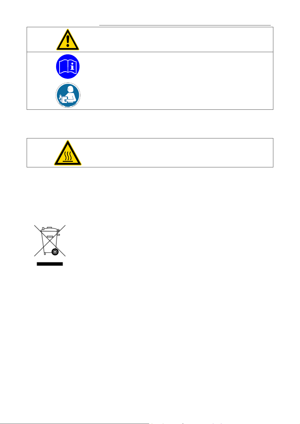
Warning label W00: Colors: yellow, black
Danger area. Attention! Observe instructions.
(operating manual, safety data sheet)
Mandatory label M018: Colors: blue, white
Carefully read the user information prior to beginning operation.
Scope: EU
Semi S1-0701 Table A1-2 #9
Carefully read the user information prior to beginning operation.
Scope: USA, NAFTA
Warning label W26: Colors: yellow, black
Hot surface warning.
(The label is put on by JULABO)
2.1. Disposal
Valid in EU countries
See the current official journal of the European Union – WEEE directive.
Directive of the European Parliament and of the Council on waste electrical
and electronic equipment (WEEE).
This directive requires electrical and electronic equipment marked with a
crossed-out trash can to be disposed of separately in an environmentally
friendly manner.
Contact an authorized waste management company in your country.
Disposal with household waste (unsorted waste) or similar collections of
municipal waste is not permitted!
7
Page 8

Operator responsibility – Safety recommendations
2.2. EC Conformity
Low voltage regulations with respect to legal harmonization of the member countries concerning
EMC guideline with respect to legal harmonization of the member countries concerning
2.3. Warranty conditions
JULABO GmbH warrants its products against defects in material or in workmanship, when used
under appropriate conditions and in accordance with appropriate operating instructions
Extension of the warranty period – free of charge
The products described in the operating instructions conform to the requirements
of the following European guidelines:
electric devices for use within certain voltage limits.
electromagnetic compatibility.
JULABO GmbH
Eisenbahnstr. 45
77960 Seelbach / Germany
for a period of ONE YEAR.
With the ‘1PLUS warranty’ the user receives a free of charge extension to the warranty of up to
24 months, limited to a maximum of 10 000 working hours.
To apply for this extended warranty the user must register the unit on the JULABO web site
www.julabo.de
JULABO GmbH’s original invoice.
JULABO GmbH reserves the right to decide the validity of any warranty claim. In case of faults
arising either due to faulty materials or workmanship, parts will be repaired or replaced free of
charge, or a new replacement unit will be supplied.
Any other compensation claims are excluded from this guarantee.
8
, indicating the serial no. The extended warranty will apply from the date of
Page 9

2.4. Technical specifications
LC6
Adjustable temperature range °C -100 ... 400
Display accuracy % ±0.5 ±1Digit
Temperature stability °C >±0.03
Temperature selection digital
via keypad indication on DIALOG-Display (LCD)
remote control via personal computer indication on monitor
Temperature indication MULTI-DISPLAY (LED)
DIALOG-DISPLAY (LCD)
Resolution °C 0.01
Absolute Temperature Calibration
ATC INT °C ±9.99
ATC EXT °C ±9.99
Temperature control ICC - Intelligent Cascade Control, self tuning
parameters for control and modification
Electrical connections:
Computer interface RS232 or RS485
Programmer input 0 to 10 V / 0 to 20 mA
Temperature recorder outputs Channel 1 / 2 0 to 10 V
Channel 3 0 to 20 mA / 4 to 20 mA
Stand-by input
External alarm device 24 to 0 V DC / max. 25mA
Safety sensor „SF“ Pt100, 4-lead technique
Measurement and control sensor „INT“ Pt100, 4-lead technique
Measurement and control sensor „EXT“ Pt100, 4-lead technique
Ambient temperature °C 5 ... 40
Overall dimensions (WxDxH) In./cm 8 x 7 x 7 / 21 x 18 x 18
Weight lbs./kg 7.7 / 4
Control connector for solenoid valve 230 V / max. 1.25 A 115 V / max. 1.25 A
Mains power socket for heating device
resistive load max. 3000 W max. 1400 W
Mains power connection ±10 % V/ Hz 230 / 50 115 / 60
Total power consumption W 3100 1400
All measurements have been carried out at:
rated voltage and frequency ambient temperature: 20 °C
Technical changes without prior notification reserved.
9
Page 10

Operator responsibility – Safety recommendations
Safety installations according to IEC 61010-2-010:
Excess temperature protection adjustable from 0 °C ... 420 °C
Supplementary safety installations
High temperature warning function optical + audible (in intervals)
Low temperature warning function optical + audible (in intervals)
Supervision of the working sensor plausibility control
Alarm indication optical + audible
Environmental conditions according to EN 61 010, part 1:
Use only indoor.
Altitude up to 2000 m - normal zero.
Ambient temperature: +5 ... +40 °C (for storage and transportation)
Air humidity:
Max. rel. humidity 80 % for temperatures up to +31 °C,
linear decrease down to 50 % relative humidity at a temperature of +40 °C
Max. mains fluctuation of ±10 % are permissible.
Protection class according to EN 60 529 IP31
The unit corresponds to Class I
Overvoltage category II
Pollution degree 2
Caution:
The unit is not for use in explosive environment.
Standards for interference resistance according to EN 61326-1
This unit is an ISM device classified in Group 1 (using high frequency for internal purposes) Class
A (industrial and commercial range).
10
Page 11
Operating instructions
3. Safety notes for the user
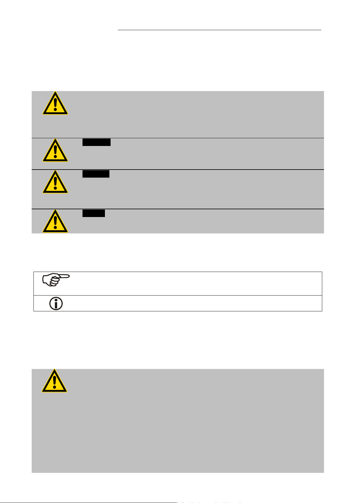
3.1. Explanation of safety notes
In addition to the safety warnings listed, warnings are posted throughout the
operating manual. These warnings are designated by an exclamation mark inside
an equilateral triangle. “Warning of a dangerous situation (Attention! Please
follow the documentation).”
The danger is classified using a signal word.
Read and follow these important instructions for averting dangers.
Warning:
Describes a possibly highly dangerous situation. If these instructions are not
followed, serious injury and danger to life could result.
Caution:
Describes a possibly dangerous situation. If this is not avoided, slight or minor
injuries could result. A warning of possible property damage may also be
contained in the text.
Notice:
Describes a possibly harmful situation. If this is not avoided, the product or
anything in its surroundings can be damaged.
3.2. Explanation of other notes
Note!
Draws attention to something special.
3.3. Safety recommendations
Follow the safety recommendations to prevent damage to persons or property.
Important!
Indicates usage tips and other useful information.
Further, the valid safety instructions for working places must be followed.
ConnOnly connect the unit to a power socket with earthing contact
(PE – protective earth)!
The power supply plug serves as a safe disconnecting device from the line and
must always be easily accessible.
Place the instrument on an even surface on a pad made of non-inflammable
material.
Observe the flash point of the bath medium used. The excess temperature
protection should be set at least 25 °C below the fire point.
Set up the heating device according to the instructions prior to connection to
the controller and ensure secure attachment to the bath.
Danger of burning and fire!
Immerse both temperature sensors in the bath medium and ensure secure
11
Page 12

Safety notes for the user
attachment.
Observe the limited working temperature range when using plastic bath tanks.
Do not stay in the area below the unit.
Make sure you read and understand all instructions and safety precautions
listed in this manual before installing or operating your unit.
Check the filling level of the bath fluid from time to time. The heater must
always be fully covered with the bath fluid!
Never operate the unit without bath fluid in the bath.
Never operate damaged or leaking equipment.
Always turn off the unit and disconnect the mains cable from the power source
before performing any service or maintenance procedures, or before moving
the unit.
Transport the unit with care.
Sudden jolts or drops may cause damage in the interior of the unit.
Always empty the bath before moving the unit.
Never operate equipment with damaged mains power cables.
Observe all warning labels.
Never remove warning labels.
Always turn off the unit and disconnect the mains cable from the power source
before cleaning the unit.
Repairs are to be carried out only by qualified service personnel.
Some parts of the bath cover may become extremely warm during continuous
operation. Therefore, exercise particular caution when touching these parts.
Use safety glasses!
12
Page 13
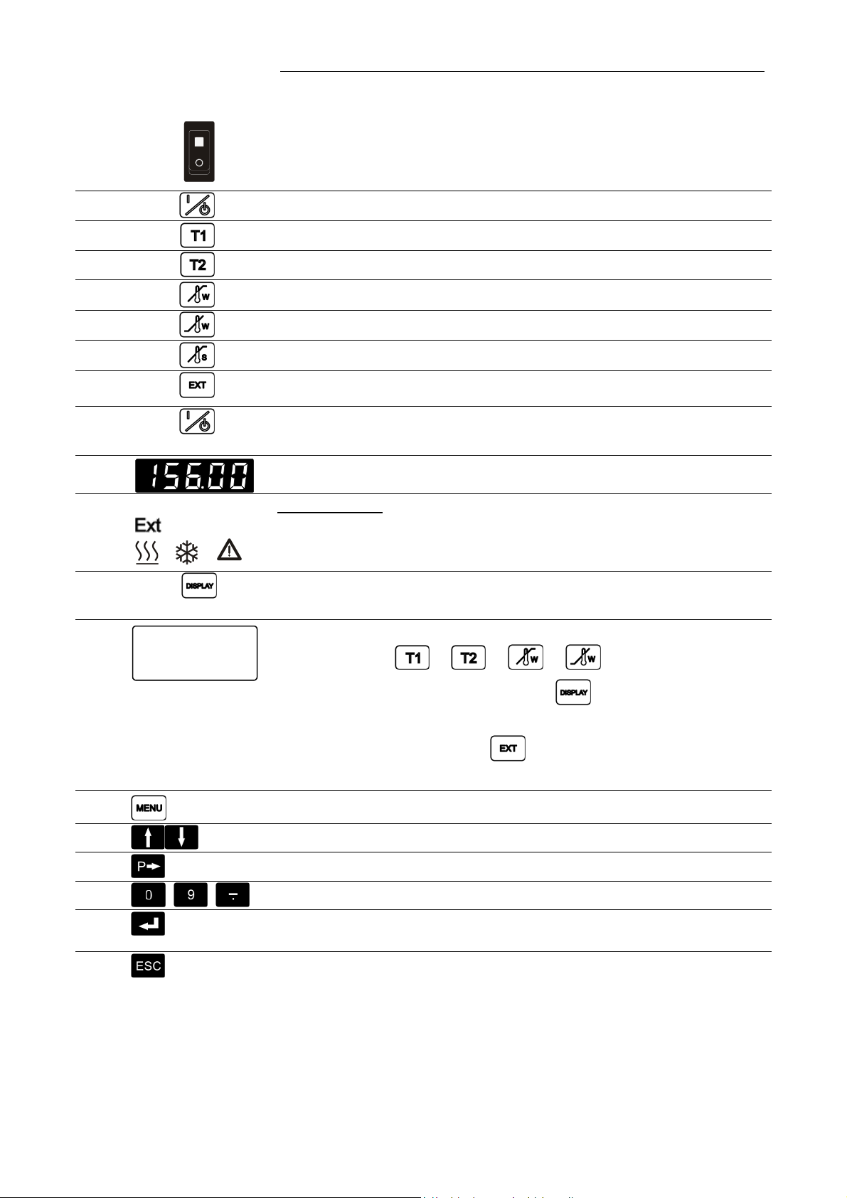
4. Operating controls and functional elements
1
Mains power switch, illuminated
2
3
4
5
6
7
8
9
Start / stop key
Working temperature T1
Working temperature T2
High temperature warning limit
Low temperature warning limit
Safety temperature
Adjustable excess temperature protection (safety temperature)
Control type: internal/external control
10 MULTI-DISPLAY (LED) temperature indication
/ /
11
Indicator lights:
Temperature indication - external actual value
Heating / Cooling / Alarm
Display of internal/external actual value
12
Setp.1: 37.00°C
ExtAct: 37.00°C
Power: 100 %
Control: intern
DIALOG-DISPLAY (LCD) for indication of:
Line 1: Setpoint
or or or
Line 2: Internal or external actual value
13
14
15
16
17
18
Line 3: Heating power in %
Line 4: Control type: internal /
external control
MENUE key - for selecting the menu functions
Cursor keys - Select menu items
P-key Selecting parameters
Numeral keypad: numerals 0 to 9; minus / decimal point
Enter key 1) Store value / parameter
2) Next lower menu level
Escape key 1) Cancel entries
2) Return to a higher menu level
13
Page 14
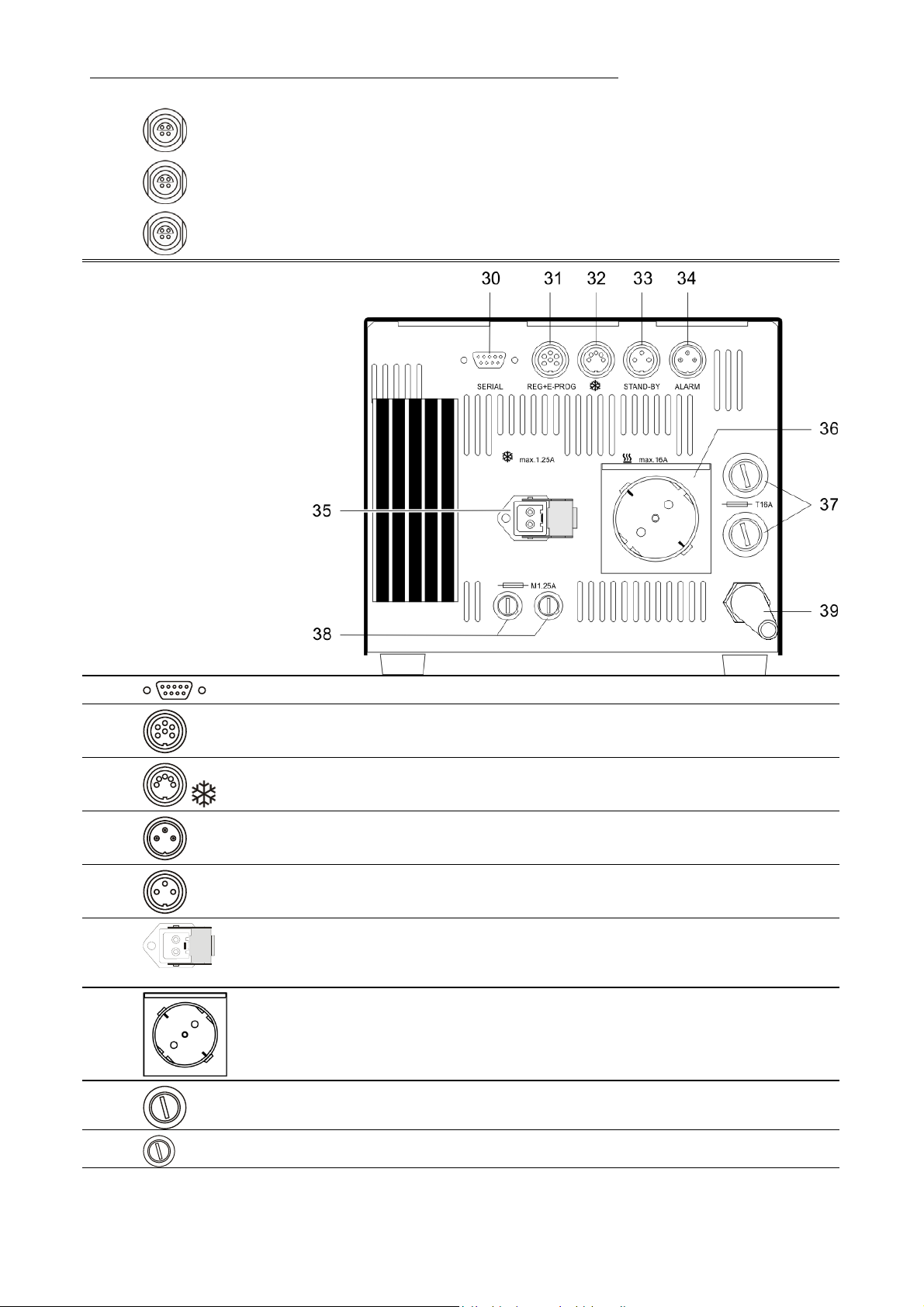
Operating controls and functional elements
Socket for safety sensor
19
20
21
Rear view
SF
INT
EXT
Socket for internal measurement and control sensor
Socket for external measurement and control sensor
30 SERIAL
31 REG+E-PROG
32
33 STAND-BY
34 ALARM
35
36
37
38
39 Mains power cable with plug
Interface RS232/RS485
Programmer input and temperature recorder output
Socket: control cable of JULABO refrigerated circulator
or output for alarm messages
Stand-by input (for external emergency switch-off)
Alarm output (for external alarm signal)
Control output for solenoid valve
230 V / max. 1.25 A
115 V / max 1.25 A
Grounded mains socket for heating device
(max. resistive load 3000 W)
(230 V / 3000 W max. resistive load)
(115 V / 1400 W max. resistive load)
Mains fuses T16A at 230 V
T12,5 at 115 V
Fuses T 1.25 A (for connectors 35)
14
Page 15
5. Operating procedures
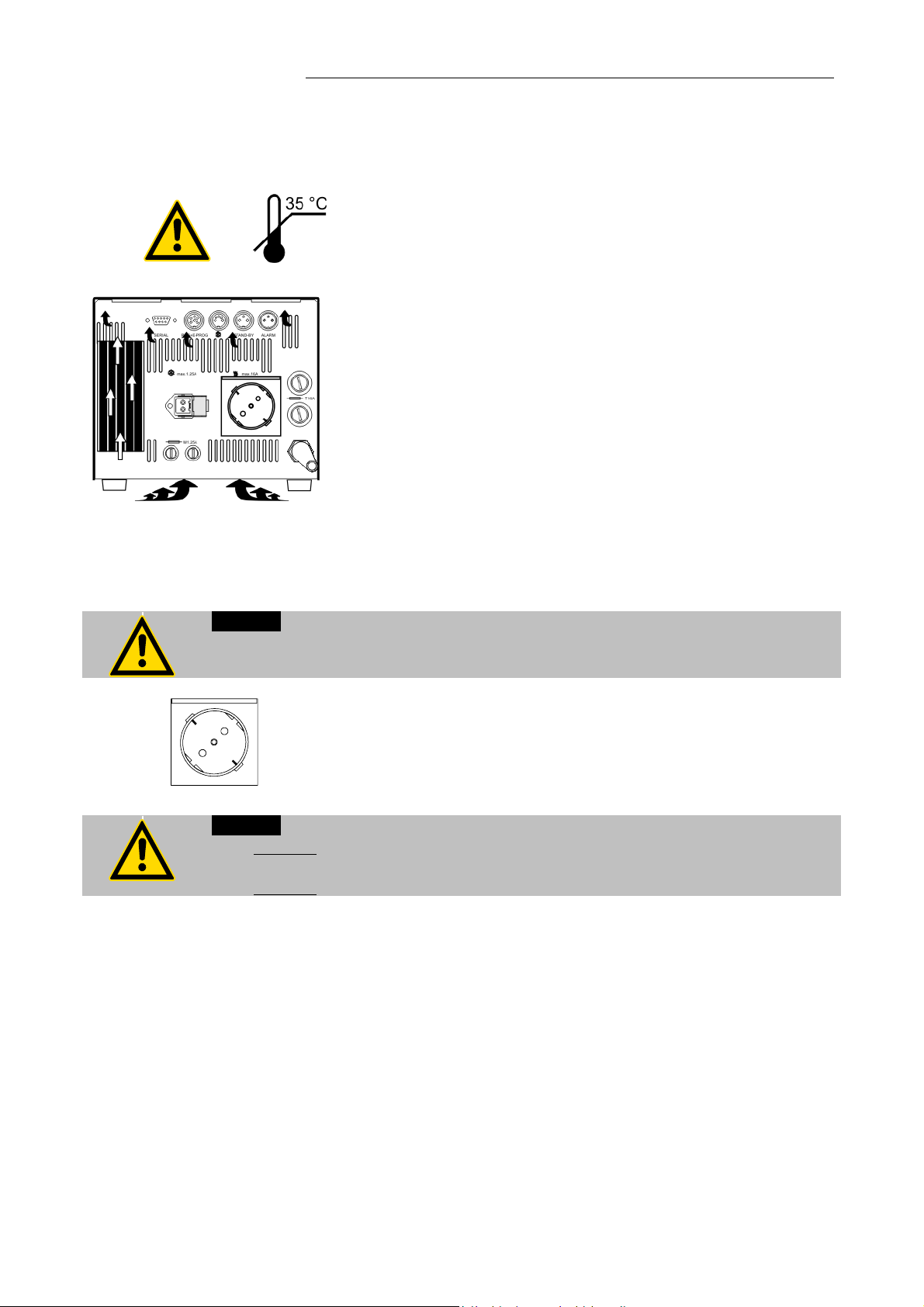
5.1. Installation
5.2. Connecting a heating device
Caution:
Set up the heating device according to the instructions or securely fix the unit in the
bath tank using appropriate means. Danger of burning and fire!
The unit should be set up at a dry location.
Place the unit in an upright position and do not obstruct the
A wall distance of at least 10 cm must be maintained for
If one or more temperature controllers are set up in a
The ambient temperature must not exceed 35 °C. Ambient
Do not set up the unit in the immediate vicinity of heat
Connect the power plug to the grounded mains socket (36) on
the rear of the programmable controller.
ventilation.
ventilation, allowing internal heat
to be conducted away from the unit.
cabinet for example, take care of good ventilation (waste
heat per unit = approx. 60 Watts).
temperatures above 35 °C result in a failure of the unit.
sources and do not expose to sun light.
+
Caution:
Max. resistive load 3000 W at 230 V. Max. current 16 A.
Max. resistive load 1400 W at 115 V. Max. current 12 A.
15
Page 16

Operating procedures
5.3. Connecting the temperature sensors
To avoid error message and safety shutdown (see page 40),
attach sensors “SF” and “INT” before switching the instrument
ON.
Attach the working sensor to socket labeled “INT” and the
safety sensor to socket labeled “SF”.
Sensor calibration:
When the controller is first placed into operation or whenever a
sensor is replaced, a working sensor calibration must be
carried out (ATC - see page 39).
5.4. Controlling an intermittent cooling water supply
Caution:
Place both sensors into the bath medium and securely fix the sensors.
The control output (35) is intended for the attachment of a
solenoid valve (230 V or 115 V - max. 1.25 A) which can be
used to control the flow of a liquid coolant. The flow of a
coolant is indicated by the illumination of a green indication
light on the control panel of LC6.
The solenoid valve is designed to be attached to the coolant
supply line.
Order-No. Description
8 980 703-3 Solenoid valve (230 V)
8 980 703-2 Solenoid valve (115 V)
Caution:
Securely attach all tubing to prevent slipping.
16
Page 17

5.5. Applications
Controlling an open bath with a direct heating device and internal control:
A heating device is used to heat the bath fluid.
Both the measurement and control sensor „INT“ and the safety sensor „SF“ must be connected
to the LC6 and immersed in the bath.
If a bath is to be operated at or near the ambient temperature, countercooling may be
necessary to ensure bath stability. This is accomplished by circulating a coolant such as tap
water through a cooling coil immersed in the bath. The flow of the coolant is controlled
automatically by the solenoid valve.
19 Connector „SF“ 19a Safety sensor
20 Connector „INT“ 20a Measurement and control sensor
20b Measurement sensor
21 Connector „EXT“ 21a Measurement and control sensor
35 Connector for solenoid valve 35a Solenoid valve
36 Mains socket for heating device 36a Heating device / heating hood
43 Cooling coil
44 Tap water connection
45 Cooling water drain
40 Stirrer motor for bath circulation
41 Bath tank
42 Round bottom flask
17
Page 18

Operating procedures
Controlling an open bath with an indirect heating device and internal control:
The bath fluid is heated with a device providing indirect heat, such as a heating hood.
Both the measurement and control sensor „INT“ and the safety sensor „SF“ must be connected
to the LC6 and immersed in the bath.
Controlling an open bath with an indirect heating device and external control:
The bath liquid is heated indirectly with a water bath for example.
The measurement „INT“ and safety „SF“ sensors must be immersed in the water bath.
The measurement and control sensor „EXT“ must be immersed in the external bath liquid.
18
Page 19

6. Operating procedures
6.1. Power connection
Caution:
Only connect the unit to a power socket with earthing contact (PE – protective
6.2. Switching on / Selecting the language
earth)!
The power supply plug serves as safe disconnecting device from the line and
must be always easily accessible.
Never operate equipment with damaged mains power cables.
Regularly check the mains power cables for material defects (e.g. for cracks).
We disclaim all liability for damage caused by incorrect line voltages!
Make sure that the line voltage and frequency match the supply
voltage specified on the type plate.
Deviations of ±10 % are permissible.
Switching on:
Turn on the mains power switch.
The unit performs a self-test.
All segments of the 5-digit MULTI-DISPLAY (LED), all
indicator lights and the DIALOG-DISPLAY (LCD) will
illuminate.
Then the software version (example: n 1.11) appears. The
display "OFF" indicates the unit is ready to operate (standby
mode).
The programmable controller enters the operating mode
activated before switching the programmable controller off:
keypad control mode (manual operation) or
remote control mode (operation via personal computer).
Selecting the language:
There are two options for the language of the DIALOGDISPLAY (LCD): German or English. Select the desired
language in the MENUE level under the configuration
submenu.
Press the respective keys in the following order:
1. MENUE key
2. Enter key
3. Cursor key
4. P key
5. Enter key
6. Escape key
The DIALOG-DISPLAY (LCD) helps to follow up the
individual settings. (example: swap the language from
German to English.)
1 x
1 x
4 x
1 x
1 x
2 x
19
Page 20

Manual operation
7. Manual operation
7.1. Start - Stop
Start:
The unit also enters the safe operating state "OFF" or "r OFF after a mains power
interruptance. The temperature values entered via the keypad remain in memory.
7.2. Setting the temperatures
With the programmable controller in keypad control mode, press the start/stop key
to restart operation.
With the programmable controller in remote control mode, the personal computer
must first resend the parameters set via the interface before the circulator may be
restarted.
Press the start/stop key
The MULTI-DISPLAY (LED) indicates the actual bath
temperature. (example: 21.03 °C)
Stop:
Press the start/stop key
The MULTI-DISPLAY (LED) indicates the message "OFF".
This setting may be carried out with the programmable
controller being in operating state Start or Stop!
.
.
Setting the working temperature "T1":
Press the setpoint key .
The value previously set appears on the DIALOGDISPLAY (LCD) (example: 50.00°C).
A flashing segment indicates that a value needs to be
entered.
Use the keypad to enter the new value (example: 37.00
°C).
Press enter to store the selected value.
Setting the working temperature "T2":
Press the setpoint key .
Follow the instructions
for "T1" (example: 25.50 °C).
20
Page 21

7.3. Warning functions
Selecting the working temperature:
Press the setpoint key
Press the setpoint key
More protection for your samples in the bath!
An audible signal sounds in intervals when the actual
temperature value exceeds one of the set limits (patented).
Setting the high temperature limit:
and then enter .
and then enter .
Press the key .
The value previously set appeears on the DIALOGDISPLAY (LCD) (example: 305.00°C). A flashing segment
indicates that a value needs to be entered.
Use the keypad to enter the new value (example: 39.00
°C).
Note:
The warning functions will only be triggered when the actual bath temperature,
after start from the „OFF“ or „rOFF“ mode, lies within the set limits for 3 seconds.
Press enter to store the value.
Setting the low temperature limit:
Press the key .
Follow the instructions
for (example: 35.00 °C).
21
Page 22

Manual operation
7.4. Setting the safety temperature (with shutdown function)
(excess temperature protection)
Press the key to indicate the safety temperature value on
the MULTI-DISPLAY and using a screwdriver
simultaneously turn the setting screw to the desired value
(example: 50 °C).
Setting range: 0 °C to 420 °C
in 2 °C steps
This safety device is independent of the control circuit. If the
temperature of the bath liquid reaches the safety temperature,
a complete shutdown of the controlled heating device is
effected.
The alarm is indicated by optical and audible signals
(continuous tone).
On the MULTI-DISPLAY (LED) and DIALOG-DISPLAY (LCD)
appears the error message "E 14".
Cancel the alarm state (see page 40).
Recommendation:
Set the safety temperature at 5 to 10 °C above the working
temperature setpoint.
+
Warning:
The excess temperature protection should be set at least 25 °C below the fire
point of the bath liquid used!
In the event of wrong setting there is a fire hazard!
We disclaim all liability for damage caused by wrong settings!
22
Page 23

7.5. Internal / external control
ext. Pt100
The programmable controller offers the possibility of internal
temperature control in a primary bath vessel or external control
directly in an external system.
Setup for external control:
Connect a Pt100 sensor to the socket „EXT“ of the
programmable controller, if necessary perform a calibration
using the „ATC Ext:“ function (see page 39) and then securely
fix the sensor in the external system.
Switching from internal to external control:
Press the key
in operating state “OFF“ to select the
control type.
The DIALOG-DISPLAY (LCD) indicates the effective control
type.
Press the start/stop key
.
Temperature indication:
Both actual temperatures are indicated at the same time:
1) on the MULTI-DISPLAY (LED)
2) on the DIALOG-DISPLAY (LCD).
Press the key
to swap the values on the displays.
The indicator light „Ext“ refers to the indication on the
MULTI-DISPLAY (LED).
Caution:
Place the external sensor into the bath medium and securely fix the sensor.
23
Page 24

Menu functions
8. Menu functions
Press the MENUE key
Use the up/down cursor keys
submenu and press enter
Press escape
to return to the previous menu level.
to enter the menu level.
to select the desired
.
24
Page 25

8.1. Configuration
By means of the configuration functions, operation of the
programmable controller can be optimized for the current
application.
Press enter
Use the up/down cursor keys
desired option. A flashing line indicates that a value needs
to select the configuration submenu.
to select the
to be entered.
Press the P-key
enter
.
Press escape
to select the parameter and press
to return the previous menu level.
Identification
When performing an identification for the controlled system
(temperature application system), the control parameters Xp,
Tn and Tv will be automatically determined and stored.
Possible parameters:
off - no identification.
The control parameters ascertained during the last
identification are used for control purposes.
once - single identification
The programmable controller performs a single
identification of the controlled system after start.
After the identification process the parameter is
automatically set to “off“.
always - continual identification
The programmable controller performs an identification of
the controlled system whenever a new setpoint is to be
reached.
NOTE: Use this setting only when the temperature
application system changes permanently.
25
Page 26

Menu functions
REG+E-PROG
Note:
Requirement for an identification of the controlled system:
The programmable controller must heat to a setpoint
temperature at least 10 °C above the previous setpoint
using the adjusted heating power.
When the adjusted control parameters Xp, Tn and Tv are
too high, this requirement may not be given with respect to
on how much the setpoint temperature has to change. In
this case, prior to carrying out an identification in the „OFF“
state, set the control parameters to lower values.
Recommended setting for internal control:
Xp = 1.0 °C
Tn = 80 s
Tv = 8 s
Setpoint
The programmable controller provides three possibilities for
the setpoint selection. The selected mode is indicated on the
DIALOG-DISPLAY (LCD).
Possible parameters:
keyb- via keypad (working temperature T1 or T2) or via the
eprog - via the analog interface REG+E-PROG (21) through
integrated programmer.
an external programmer.
26
SERIAL
RS232 - via the serial RS232/RS485 interface (20) through a
PC or superordinated data system.
Page 27

Autostart
Note:
The programmable controller has been configured and
supplied by JULABO according to N.A.M.U.R.
recommendations. This means for the start mode, that the unit
must enter a safe operating state after a power failure (nonautomatic start mode). This safe operating state is indicated by
„OFF“ or „rOFF“, resp. on the MULTI-DISPLAY (LED). A
complete shutdown of the main functional elements such as
heater and circulation pump is effected simultaneously.
Should such a safety standard not be required, the
AUTOSTART function (automatic start mode) may be
activated, thus allowing the start of the programmable
controller directly by pressing the mains power switch or using
a timer.
STAND-BY
Possible parameters:
on - AUTOSTART on
off - AUTOSTART off
Warning:
For supervised or unsupervised operation with the AUTOSTART function, avoid
any hazardous situation to persons or property.
The programmable controller does no longer conform to N.A.M.U.R.
recommendations.
Take care you fully observe the safety and warning functions of the
programmable controller.
Stand-by input
External stand-by for emergency switch-off
(connector - see page 6)
Possible parameters:
no - stand-by input is ignored
yes - stand-by input is active
Language
There are two options for the language of the DIALOGDISPLAY (LCD): German or English.
Possible parameters:
German (deutsch)
English (engl.)
27
Page 28

Menu functions
8.2. Control parameters
Xp =
When performing an identification for the controlled system
(temperature applications system) (see page 25), the control
parameters Xp, Tn, and Tv will be automatically determined
and stored.
Each parameter may be manually set via the keypad if
necessary, to allow optimum control performance.
Press enter
parameters“.
Use the up/down cursor keys
to select the submenu „control
to select the
desired option. A flashing segment indicates that a new
value needs to be entered.
Use the numeral keypad to set the value and then set with
enter
Press escape
(example: Xp = 2.5 °C).
to return to the previous menu level.
Optimization instructions for the PID control parameters:
The heat-up curve reveals inappropriate control settings.
(example: working temperature T1)
optimum setting
Inappropriate settings may produce the following
heat-up curves:
Xp too low
Tv/Tn too low
Xp too high
or
Tv too high
Tv/Tn too high
or
Xp too high
28
Page 29

8.3. Start of a profile
1.
2.
The start menu of the programmable programmer allows
calling up and defined starting of one of six previously stored
temperature profiles.
There are two possibilities for manually starting a
program:
1. Starting a program from the OFF status:
The programmer switches back to the OFF status at the
end of the program.
2. Starting a program from the operating status.
The programmer is started with the Start key
bath is heated to the desired temperature, for example
100 °C. At the end of the program, the programmer
switches to the operating status and holds the bath
temperature stable at 100.00 °C.
Press enter
Use the up/down cursor keys
to select the submenu „Profile Start“.
to select the
desired option.
A flashing segment indicates that a number needs to be
entered.
Start Profile 0 to 5
at Step 0 to 60
Loops 1 to 99
Enter the desired number and set each entry with enter
, and the
.
Start no / yes (manual start)
or
time (via integrated timer)
A flashing line indicates that a parameter needs to be
entered.
Press the P-key
and press enter
to select the respective parameter
.
29
Page 30

Menu functions
Example: hour.min 6:00 h
When selecting the parameter time, a new menu level is
called up for entry of the start time.
A flashing segment indicates that a start time needs to be
entered.
hour.min Start time
Day.Mon day and month
Year year
Set each entry with enter
.
Start no / yes
A flashing line indicates that the parameter „yes“ needs to
be entered.
Press the P-key
enter
The programmable controller switches to waiting mode and
.
to select the parameter and press
a flashing line „wait“ appears on the DIALOG-DISPLAY
(LCD). The start time and actual time are permanently
indicated on the display.
30
Page 31

A
3
S
Y
8.3.1. Interrupting a profile
K
1
TAND-B
2
Warning:
Interrupting a profile:
Press the start/stop key
to interrupt or restart a profile.
The setpoint and time period set for the corresponding section
are thus stopped at the values presently achieved.
The programmable controller is put on hold and the message
„pause“ flashes on the DIALOG DISPLAY (LCD).
A profile can be interrupted or restarted by an external
emergency shut-off.(see page 6).
CAUTION:
This is not an actual emergency shut-off!
The setpoint control and the timer are interrupted by
breaking the contact “AK”. The programmer switches to the
waiting position, while displaying this condition with a
blinking LCD display.
Important:
To achieve this, the Stand-by condition must first be
activated and the Autostart function turned on.
(see page 27).
Following a power interruption, it would be possible in this condition for the
programmer to restart automatically. The safety and warning functions of the
programmer should always be used to their fullest capacity.
See warning page 27
Termination of a profile:
A profile can be terminated by pressing the escape key
.
The programmer switches back to the Start menu.
Press escape
cursor keys
The execution of another temperature profile can now be
again to leave the menu or use the
to remain in the Start menu.
prepared if necessary.
31
Page 32

Menu functions
8.4. Integrated programmer
The integrated programmer allows any desired temperature
program sequences to be realized. Such a temperature
sequence is called profile. A profile consists of individual
sections defined by duration (t:) and target temperature.
Target temperature is the setpoint (T:), that is achieved at the
end of a section. The programmer uses time and temperature
difference values within a section to calculate a temperature
ramp.
Press enter
Use de up/down cursor keys
desired option. Then press enter
to select the submenu „Int. Programmer“.
to select the
to open.
A flashing segment indicates that a number or value needs
to be entered.
Edit Compile profiles
Display sections
Delete Delete sections
Print Print a programmed profile
Set clock Set the real time on the programmable
controller
Setting the clock
Examples:
The integrated clock provides the flexibility to start a profile at
any date and time. The clock is preset at the JULABO factory.
Lines 1 to 3:
Check for correctness of the preset date and time and
correct if necessary.
The time is diplayed permanently in line 4.
Use the numerals to set time, date and year and set each
entry with enter
.
Press escape
to return to the previous menu level.
32
Page 33

Edit
Examples:
Profile No. 1
Step
Setpoint
Time
Compile profiles:
A flashing segment indicates that a number needs to be
entered.
Under submenu „Edit Profile“ enter a profile number.
Six profiles may be stored (nos. 0 to 5).
Then programme the desired values for each section.
Use the keypad to set section number, target temperature
and time period. Set each entry with enter
.
When the program is running, only sections having
complete information for target temperature and time period
are considered.
It makes sense, to leave out section numbers in the profile,
in order to use them later for corrections in the profile.
Important:
If a time of 00:00 is set for a profile, the profile is continued
with the next section only after the setpoint temperature
(±0.2 °C) is reached.
Press escape
to return to the previous menu level.
Example:
Step (No.) 1 3 5 6 9 11 14
Setpoint (°C) 50 50 100 100 80 80 20
Time (h:m) 00:08 00:02 00:10 01:05 00:10 00:05 00:30
Step
Display sections:
Use the cursor keys
„Step“, enter the desired number and press enter
The values previously set are displayed.
to select the submenu
.
33
Page 34

Menu functions
Delete
A flashing segment indicates that the respective profile
number needs to be entered in which one or more
consecutive sections are to be deleted.
In lines 2 and 3 of the DIALOG DISPLAY (LCD) enter the
numbers of the sections to be deleted. Press enter
delete no / yes
.
Profile 1
Step 0 not defined!
Step 1 50 00:08
Step 2 not defined!
Step 3 50 00:02
Step 4 not defined!
Step 5 100 00:10
Step 6 100 01:05
Step 7 not defined!
Step 8 not defined!
Step 9 80 00:10
Step 10 not defined!
Step 11 80 00:05
Step 12 not defined!
Step 13 not defined!
Step 14 20 00:30
Step 15 not defined!
etc.
Press the P-key
press enter
to select the parameter „yes“ and
.
Line 4 indicates the deletion.
Example:
Delete section 8 to section 34 in profile 3.
Press escape
to return to the previous menu level.
Print
Each profile may be printed via the serial interface for control or
documentation.
A flashing segment indicates that the number of the profile
to be printed needs to be entered.
Print no / yes
Press the P-key
press enter
to select the parameter „yes“ and
.
Printing is indicated in line 2.
This printing example shows the profile given as example on
page 33.
34
Page 35

8.5. Analog inputs/outputs
This submenu enables setting of the input and output values
for the programmer input and the temperature recorder outputs
of socket REG+E-PROG (21).
Press enter
to select the inputs/outputs submenu.
Use the up/down cursor keys
desired option and press enter
to select the
to open.
Chan.1 voltage output for recorder (V)
Chan.2 voltage output for recorder (V)
Chan.3 current output for recorder (mA)
EPROG external programmer input
First define the desired output value for channels 1 to 3
Press the P-key
with enter
to select the desired output value and set
:
Setpoint active setpoint temperature
(T1, T2, integr. programmer/ext. programmer)
ActInt internal actual temperature value
(bath temperature)
ActExt external actual temperature value
(external sensor)
Power periodic or intermittent heating or cooling
or
Then select the display size for channels 1 to 3:
Channel 1 and 2 voltage outputs
Assign the voltage values of 0 V to the lowest and 10 V to
the highest necessary temperature or power rating required
as an output value (°C or %).
Current output channel 3
Assign the current values 0 mA or 4 mA to the lowest and
20 mA to the hightest temperature or power rating required
as an output value (°C or %).
The current output offers 2 ranges for selection:
0 to 20 mA and 4 to 20 mA.
Select the desired range by pressing the P-key
and set with enter
.
The LCD display changes automatically.
35
Page 36

Menu functions
0 V
10 °C 210 °C
200 K
197 °C 202 °C
5 K
0 mA
4 mA
20 mA
Examples:
lowest temperature value: 10 °C
highest temperature value 210 °C
Fig. shows 200 C scaled to paper width
rise: 50 mV/°C
lowest temperature value: 197 °C
highest temperature value: 202 °C
Fig. shows 5 C scaled to paper width
rise: 2000 mV/°C
EPROG - Input
This input is necessary when the nominal value is to be
determined and set by an external programmer.
Connect the external programmer to socket (21)
REG+E-PROG of the programmable controller.
The programmer input of the programmable controller can
be matched to the output signal of the external
programmer.
Voltage voltage input
Current current input
Select the desired input value with the P-key
with enter
.
and set
„L Value“ - Setting the LOW value::
Adjust and set the lowest desired working temperature on
the programmer (e.g. 0 C).
Enter this same temperature on the programmable
controller by pressing the appropriate buttons on the
keypad and press enter
to set.
„H Value“ - Setting the HIGH value:
Adjust and set the highest desired working temperature on
the programmer (e.g. 300 C).
Enter this same temperature on the programmable
controller by pressing the appropriate buttons on the
keypad and press enter
to set.
Return to the standard display by pressing escape
.
36
Page 37

C
A
Example:
Setting a temperature of 50 C on the external programmer!
The value adjusted and set on the external programmer is
displayed in line 4 of the DIALOG-DISPLAY (LCD) for control
purposes (Example: ExtSet: 50.0 C).
After returning the LCD display to standard display by pressing
300
250
200
150
100
80
60
40
20
°
B
12345678910V
246810 14 18 20 m
escape
(„Setpoint“ - see page 26) this value is displayed
in line 1 (Example: EPROG 50.00 C).
This EPROG input enables the use of different voltage and
current values as program parameters.
„L Value“ - Setting the LOW value:
1) Adjust and set the lowest desired value on the voltage or
current source resp. (Example A: 1 V).
2) Assign a lower temperature threshold value to this
adjusted voltage/current value by pressing the appropriate
buttons on the keypad of the programmable controller
A
(Example A: 20 C ) and set by pressing enter
.
„H Value“ - Setting the HIGH value:
1) Adjust and set the highest desired value on the voltage
or current source resp. (Example A: 10 V).
2) Assign an upper temperature threshold value to this
adjusted voltage/current value by pressing the appropriate
buttons on the keypad of the programmable controller
(Example A: 200 C) and set by pressing enter
Return to the standard display by pressing escape
.
.
Example B in the diagram serves to illustrate that the end point
values are freely selectable.
Example out of diagram A:
Adjusting the voltage source for an output of 7.6 V!
Line 4 of the DIALOG-DISPLAY (LCD) shows the externally set
setpoint value. The programmable controller calculates this
value from the rise angle of the two predecided end points (in
example A: 7.6 V correspond to an external setpoint
temperature of 152.0 C ).
After returning the LCD display to standard display by pressing
escape
, this value is displayed in line 1
(Example: EPROG 152.00 C).
Notice:
If this adjustment is not correctly performed at two different points, the setpoint
setting will be incorrect.
37
Page 38

Menu functions
8.6. Limits
When operating the programmable controller under external
control, band limiting is active. The preset value determines the
maximum temperature difference between the internal bath
and the external load. This adjustment possibility prevents
sensitive equipment and temperature devices from damage.
Heating and cooling power of the programmable controller are
adjustable.
100 % corresponds to the values in the technical specifications
of the equipment.
Select the submenu „Limits“ with enter
.
Select the desired option with the up/down cursor keys
.
A flashing digit indicates that a value needs to be entered.
Band 0 to 200 °C
HeatingMax 0 to 100 % in steps of 1 %
CoolingMax 0 to 100 % in steps of 1 %
To set the newly entered value press enter
To return to the previous menu level press escape
.
.
8.7. Interface
The interface parameters are set by selecting the submenu
„Interface“ on the programmable controller. Normally, this is a
one-time-only adjustment.
Press enter
to select the submenu „Interface“.
Select the desired option with the up/down cursor keys
. Enter the desired value for the flashing digit.
Type RS232 / RS485
Baudrate 2400/4800/9600
Parity none/even/odd
Handshake software handshake/hardware handshake
Address 0 to 127
Press the P-key
set with enter
Return to the previous menu level with escape
to select the desired parameter and
.
.
38
Page 39

8.8. Sensors
Thermometer (T
ATC - Absolute Temperature Calibration
Select the submenu „Temp.Sensor“ with enter
.
Select the desired option with the up/down cursor keys
. A flashing digit indicates that a value needs to
be entered i.e. set.
ATC Int.: used during the configuration of a Pt100 sensor
attached on the socket labeled “INT”.
ATC Ext.: used during the configuration of a Pt100 sensor
attached on the socket labeled “EXT”.
Setpoint range for internal or external calibration: ±9.99 °C.
Enter the desired correction value and set this value by
pressing ENTER
.
)
M
Example:
1. Immerse temperature sensors individually or together in a
calibration bath at 50°C, for example, and allow the reading
to stabilize.
Programmable controller (T
2. Both temperature values are displayed simultaneously on
the controller readout:
on the MULTI-DISPLAY:
)
L
49.20°C for temperature sensor attached to the socket
labeled “INT”.
on DIALOG-DISPLAY:
51.22°C for temperature sensor attached to the socket
labeled “EXT”.
3. Calculate the temperature difference between the
programmable controller (T
(change in T = T
ATC parameter.
4. For ATC Int, enter the correction value (for example
- TL) and enter the correction value as the
M
) and the thermometer (TM)
L
0.80 °C) with the keypad. Confirm entry with the Enter key
.
5.
6. For ATC Ext, enter the correction value,
(for example -1.22 °C) followed by the Enter key
7. Return to standard display with the Escape key
.
.
39
Page 40
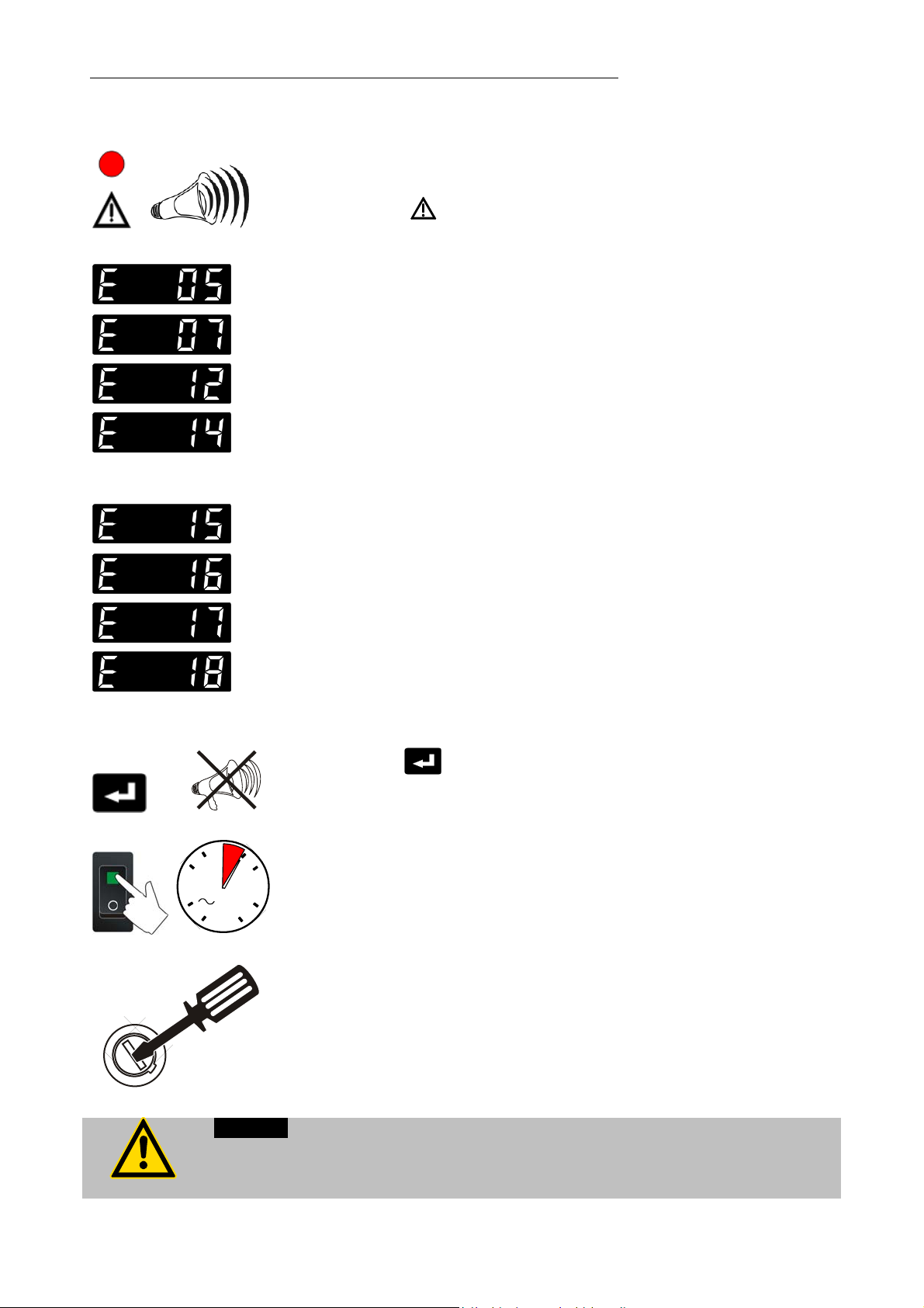
Troubleshooting guide / Error messages
9. Troubleshooting guide / Error messages
Whenever the microprocessor electronics registers a failure, a complete
shutdown of the heating device is performed.
+
The alarm light "
Cable of the working temperature sensor interrupted or short-
circuited.
Other errors
Error in A/D converter.
Safety sensor defect.
The safety temperature value lies below the working temperature
setpoint.
Set the safety temperature to a higher value.
External control selected, but external Pt100 sensor „EXT“ not
connected.
Heating circuit interrupted.
Heating circuit short-circuited or interrupted.
Defective alarm relay.
" illuminates and a continuous signal tone sounds.
Press enter
60
4 s
30
Warning:
Before exchanging the fuses, turn off the mains power switch and disconnect the
power plug from the mains socket!
Use only fine fuses with the specified nominal value.
After eliminating the malfunction, press the mains power switch off
and on again to cancel the alarm state.
If the unit cannot be returned to operation, contact an authorized
1545
JULABO service station.
Fuses
The mains fuses on the rear of the unit may easily be exchanged as
shown on the left.
Fine fuses 230 V, T16 A, dia. 5 x 20 mm
115 V, T12.5 A, dia. 6.3 x 32 mm
T1.25 A, dia. 5 x 20 mm
to quit the audible signal.
40
Page 41

9
5
10. Electrical connections
Notice:
Use shielded cables only.
Accessories:
The shield of the connecting cable is electrically connected to the plug housing.
SERIAL
1
6
Order No. Description
RS232/RS485 serial interface (30)
This port can be used to connect a computer with an RS232 or
RS485 cable for remote control of the programmable
controller.
Pin assignments RS232:
Pin 2 RxD Receive Data
Pin 3 TxD Transmit Data
Pin 5 0 V Signal GND
Pin 7 RTS Request to send
Pin 8 CTS Clear to send
Pin 1; 4; 6, 9 Reserved - do not use!
Pin assignments: RS485
Pin 3 A
Pin 5 0 VD Signal GND
Pin 8 B
Pins 1, 2, 4, 6, 7, 9 Reserved - do not use!
Interface correspondence: RS232:
Programmable controller Computer
9-pole plug 9-pole socket
Pin 2 RxD Pin 3 TxD
Pin 3 TxD Pin 2 RxD
Pin 5 GND Pin 5 GND
Pin 7 RTS Pin 8 CTS
Pin 8 CTS Pin 7 RTS
8 980 073 RS232 interface cable 9-pol./9-pol. , 2,5 m
8 900 110 USB interface adapter cable
41
Page 42

Electrical connections
3
6
4
Programmer input / temperature recorder output (31)
2
1
REG+E-PROG
4
5
2
4
13
5
Analog inputs / outputs see page 35
Pin Signal
1 Voltage output Channel 1 0 ... 10 V
2 Voltage output Channel 2 0 ... 10 V
3 GND for outputs 0 V
4 Programmer input EPROG 0 to 10 V / 0 to 20 mA
5 Current output Channel 3 0 to 20 mA / 4 to 20 mA
6 GND for Progammer 0 V
Control output (32)
The
refrigerated programmable controllers or as output for alarm
messages.
Pin assignment:
Pin Signal
1 +24 V (I max. current 25 mA)
2 0 V
3 Alarm relay
4 Reserved - do not use!
5 Cooling pulse
Circuit: Operation = relay powered
Alarm = relay not powered
Alarm output (34)
connector may be used for control of JULABO
ALARM
2
3
1
SF
INT
EXT
(for external alarm signal)
This potential-free change-over contact is activated in case of
an alarm when pins 2 and 3 are connected.
Switching capacity max. 30 W / 40 VA
Switching voltage max. 125 V/
Switching current max. 1 A
Socket for temperature sensors (19, 20, 21)
Pin assignment:
Pin Signal
1 Current+
2 Voltage+
3 Voltage 4 Current-
42
Page 43

A
K
2
3
1
1
STAND-BY
AK
2
3
STAND-BY input (33) (for external emergency switch-off)
Pin assignment: Pin Signal
1 not connected
2 5 V / DC
3 0 V
Use shielded cables only.
Activate the stand-by input:
Under menu item Stand-by, set the parameter to „yes“
(see page 27).
Connect an external contact 'AK' (e.g. for emergency
switch-off) or an alarm contact of the superordinated
system.
If the connection between Pin 2 and Pin 3 is interrupted by
opening the contact 'AK', a complete shutdown of the
heating device is effected, and the unit enters the condition
"OFF".
As long as the contact remains open, line 4 of the DIALOGDISPLAY (LCD) flashes and displays the message
„STAND-BY“.
If the contact is reclosed, the programmable controller returns
to standby mode and “OFF” is displayed.
Additional tips for using the stand-by command:
The stand-by function can be used in conjunction with the
autostart feature (see page 27).
1. If the autostart function is not turned on, the stand-by input
should be used as described above.
2. If the autostart funcion is enabled, the instrument will revert
back to the original method of entering the setpoint (i.e.
keypad, RS232, analog input, etc.).
Entering the setpoint with the keypad, for example
described above, a bipolar shut-down is accompanied by
the “STAND-BY” display and the OFF status. The
programmable controller starts again when the contact is
reclosed. The temperature of the bath liquid changed during
the STAND-BY status.
Entering the setpoint with the programmer (see pages 29
and 31). The display STAND-BY appears. The setpoint
value and the time are both held at the current value. The
temperature of the bath fluid will be held constant at this
temperature. The programmer continues once the contact
is reclosed.
. As
CAUTION:
This is not an actual emergency shut-off!
43
Page 44

Remote control
Control connector (35)
11. Remote control
11.1. Setup for remote control
SERIAL
The connector may be used with solenoid valves.
Line voltage: 230 V / max. 1.25 A
115 V / max. 1.25 A
Select the „Configuration“ submenu and select the option
„Setpoint“ to define the interface (see page 26).
The interface parameters are set by selecting the submenu
„Interface“ on the programmable controller. Normally, this is a
one-time-only adjustment. (Selecting and setting menu items,
see page 38.)
Factory settings:
RS232
BAUDRATE 4800 bauds
PARITY even parity
HANDSHAKE Protocol RTS/CTS
(hardware handshake)
Data bits 7
Stop bit 1
44
Like all parameters which can be entered through the keypad, interface
parameters are stored in memory even after the programmable controller is
turned off.
Page 45

11.2. Communication with a PC or a superordinated data system
Suitable terminal programs for communicating with a PC are:
MS-Windows - TERMINAL.EXE (included with MS-Windows).
.
If the programmable controller is put into remote control mode
via the configuration level, the display will read
"r OFF" = REMOTE STOP.
The programmable controller is now operated via the
computer.
In general, the computer (master) sends commands to the
programmable controller (slave). The programmable controller
sends data (including error messages) only when the computer
sends a query.
A transfer sequence consists of:
address (RS485 interface only)
command
space (; Hex: 20)
parameter (the character separating decimals in a group is
the period)
end of file (; Hex: 0D)
The commands are divided into in or out commands.
in commands: asking for parameters to be displayed
out commands: setting parameters
The out commands are valid only in remote control mode.
When the RS485 interface is used, the three-digit instrument
address stands in front of each command.
(example: address Ad32 = A032)
Examples:
Command to set the working temperature T1 to 55.5 °C
out_sp_00 55.5
A032_out_sp_00 55.5
Command to ask for the working temperature T1:
in_sp_00
A032_in_sp_00
Response from the programmable controller:
55.5
A032_55.5
45
Page 46

Remote control
11.3. List of commands
When the RS485 interface is used, the instrument address stands in front of each command
(Axxx_).
in-commands: Asking for parameters or temperature values to be displayed.
Command
Parameter
Response of programmable controller
version
status
in_pv_00
in_pv_01
in_pv_02
in_pv_03
in_sp_00
in_sp_01
in_sp_03
in_sp_04
in_sp_05
none Number of software version (V X.xx)
none Status message, error message (see page 49)
none Actual bath temperature.
none Heating power being used (%).
none Temperature value registered by the external Pt100 sensor.
none
none Working temperature "T1"
none Working temperature "T2"
none
none
none Setpoint temperature of the external programmer
Temperature value registered by the safety sensor. "
High temperature warning limit "
Low temperature warning limit "
(socket - REG+E-PROG) .
".
".
".
in_hil_00
in_hil_01
in_mode_01
in_mode_02
in_mode_03
46
none Max. cooling power (%).
none Max. heating power (%).
none Selected working temperature:
0 = "T1".
1 = "T2".
none Identification type:
0 = no identification
1 = single identification
2 = continual identification
none Type of the programmer input:
0 = Voltage 0 V to 10 V
1 = Current 0 mA to 20 mA
Page 47

Command
in_mode_04
in_mode_05
in_par_01
in_par_02
in_par_03
in_par_04
in_par_05
Parameter
none Internal/external temperature control:
none Circulator in Stop/Start condition:
none Time constant of the external bath.
none Internal slope.
none Time constant of the internal bath.
none Band limiting (max. difference between the temperatures in
none Ratio for max. cooling power versus max. heating power.
Response of programmable controller
0 = Temperature control with Pt100 sensor „INT“.
1 = Temperature control with Pt100 sensor „EXT“.
0 = Stop
1 = Start
the internal bath and external system).
in_par_06
in_par_07
in_par_08
in_par_09
in_par_10
in_par_11
in_par_12
out commands: Setting parameters or temperature values.
Command
none Xp control parameter of the internal controller.
none Tn control parameter of the internal controller.
none Tv control parameter of the internal controller.
none Xp control parameter of the cascade controller.
none Proportional portion of the cascade controller.
none Tn control parameter of the cascade controller.
none Tv control parameter of the cascade controller.
Parameter Response of circulator
out_mode_01
out_mode_01
out_mode_02
out_mode_02
0 Use working temperature "T1"
1 Use working temperature "T2"
0 No identification.
Temperature control by using the stored parameters.
1 Single identification of controlled system after the next start.
47
Page 48

Remote control
Command
out_mode_02
out_mode_04
out_mode_04
out_mode_05
out_mode_05
out_sp_00
out_sp_01
out_sp_03
out_sp_04
Parameter Response of circulator
2 Continual identification of controlled system whenever a new
setpoint is to be reached.
0 Temperature control with Pt100 sensor „INT“.
1 Temperature control with Pt100 sensor „EXT“.
0 Stop the programmable controller = r OFF.
1 Start the programmable controller.
xxx.x Set working temperature "T1".
xxx.x Set working temperature "T2".
xxx.x
xxx.x
Set high temperature warning limit
Set low temperature warning limit
.
.
out_hil_00
out_hil_01
out_par_04
out_par_05
out_par_06
out_par_07
out_par_08
out_par_09
out_par_10
out_par_11
xxx Set the desired maximum cooling power (0 % to 100 %).
This adjustment is required only for proportionally controlled
refrigerated circulators.
xxx Set the desired maximum heating power (10 % to 100 %).
xxx Band limiting during external control.
Setting the maximum difference between the temperatures
in the internal bath and external system.
xxx Ratio for max. cooling power versus max. heating power
(0...0.99).
xxx Xp control parameter of the internal controller.
xxx Tn control parameter of the internal controller.
xxx Tv control parameter of the internal controller.
xxx Xp control parameter of the cascade controller.
xxx Proportional portion of the cascade controller.
xxx Tn control parameter of the cascade controller.
out_par_12
48
xxx Tv control parameter of the cascade controller.
Page 49

11.4. Status messages / error messages
The programmable controller sends data (including error messages) only when the computer
sends a query.
Status messages Description
00 MANUAL STOP Programmable controller in "OFF" state.
01 MANUAL START Programmable controller in keypad control
mode.
02 REMOTE STOP Programmable controller in "r OFF" state.
03 REMOTE START Programmable controller in remote control
mode.
Error messages Description
-02 REFRIGERATOR ALARM Control cable of the refrigerated circulator or
MVS solenoid valve controller short-circuited or
interrupted.
-03 EXCESS TEMPERATURE WARNING
-04 LOW TEMPERATURE WARNING
-05 WORKING SENSOR ALARM Working temperature sensor short-circuited or
-07 I2C-BUS ERROR Internal error when reading or writing the I2C
-08 INVALID COMMAND Invalid command.
-09 COMMAND NOT ALLOWED IN CURRENT
OPERATING MODE
-10 VALUE TOO SMALL Entered value too small.
-11 VALUE TOO LARGE Entered value too large.
-12 TEMPERATURE MEASUREMENT ALARM Error in A/D converter.
-13 WARNING : VALUE EXCEEDS
TEMPERATURE LIMITS
-14 TEMPERATURE/LEVEL ALARM
High temperature warning "
Low temperature warning "
interrupted.
bus.
Invalid command in current operating mode.
Value lies outside the adjusted range for the
high and low temperature warning limits. But
value is stored.
Safety temperature alarm
".
".
-15 EXTERNAL SENSOR ALARM External control selected, but external Pt100
sensor not connected.
-16 TRIAC/RELAY CONNECTION OPEN Heating circuit interrupted.
-17 TRIAC SHORTED Heating circuit short-circuited.
-18 RELAY SHORTED Defective alarm relay.
49
Page 50

Cleaning / repairing the unit
12. Cleaning / repairing the unit
Caution:
Improper maintenance or repair can result in electric shock or damage to the unit.
Repairs and any other work are to be carried out only by qualified service
personnel authorized by JULABO.
Always turn off the unit and disconnect the mains cable from the power
source before performing any service or maintenance procedures, or before
moving the unit.
Prevent humidity from entering into the unit.
Cleaning:
The controller is designed for continuous operation under normal
conditions. Periodic maintenance is not required.
Clean the outside of the unit using a wet cloth and low surface
tension water.
Repairs:
Returning a unit:
Before asking for a service technician or returning a JULABO
instrument for repair, please contact an authorized JULABO service
station.
When returning the unit:
Clean the unit and, if necessary, decontaminate the unit in order
to avoid endangering service personnel.
Attach a short fault description.
During transport the unit has to stand upright. Mark the packing
correspondingly.
When returning a unit, take care of careful and adequate packing.
JULABO is not responsible for damages that might occur from
insufficient packing.
JULABO reserves the right to carry out technical modifications with
repairs for providing improved performance of a unit.
50
 Loading...