

Page 1
English
Operating manual
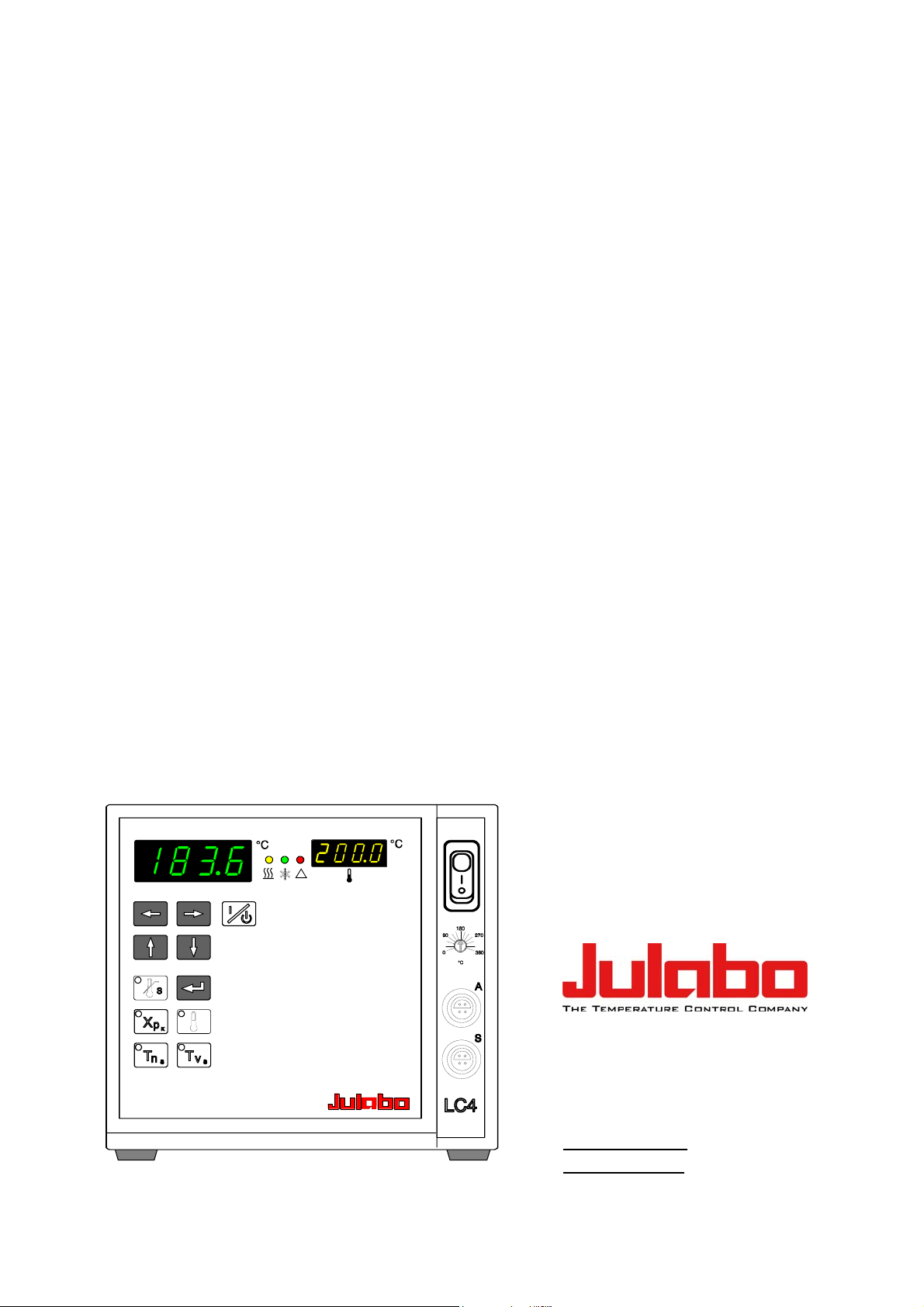
Temperature controller
LC4
!
JULABO GmbH
77960 Seelbach / Germany
Tel. +49 (0) 7823 / 51-0
Fax +49 (0) 7823 / 24 91
1.951.5200-V2 06/13
19515200-V2.doc 26.07.2013
info@julabo.de
www.julabo.de
Page 2
Congratulations!
You have made an excellent choice.
JULABO thanks you for the trust you have placed in us.
This operating manual has been designed to help you gain an understanding of the operation
and possible applications of our circulators. For optimal utilization of all functions, we
recommend that you thoroughly study this manual prior to beginning operation.
The JULABO Quality Management System
Temperature control devices for research and industry are developed,
produced, and distributed according to the requirements of ISO 9001
and ISO 14001. Certificate Registration No. 01 100044846
Unpacking and inspecting
Unpack the circulator and accessories and inspect them for possible transport damage.
Damage should be reported to the responsible carrier, railway, or postal authority, and a
damage report should be requested. These instructions must be followed fully for us to
guarantee our full support of your claim for protecting against loss from concealed damage.
The form required for filing such a claim will be provided by the carrier.
Printed in Germany Changes without prior notification reserved
Important: keep operating manual for future use
2
Page 3

INDEX
OPERATING MANUAL ..................................................................................................... 4
1. INTENDED USE ........................................................................................................ 4
1.1. Description ........................................................................................................ 4
2. OPERATOR RESPONSIBILITY – SAFETY RECOMMENDATIONS ........................ 4
2.1. Disposal ............................................................................................................ 6
2.2. EC Conformity ................................................................................................... 7
2.3. Warranty conditions .......................................................................................... 7
2.4. Technical specifications .................................................................................... 8
OPERATING INSTRUCTIONS ....................................................................................... 10
3. SAFETY NOTES FOR THE USER ......................................................................... 10
3.1. Explanation of safety notes ............................................................................. 10
3.2. Explanation of other notes .............................................................................. 10
3.3. Safety recommendations ................................................................................ 10
4. OPERATING CONTROLS AND FUNCTIONAL ELEMENTS .................................. 12
LC4
5. OPERATING PROCEDURES ................................................................................. 14
5.1. Installation ....................................................................................................... 14
5.2. Power connection ........................................................................................... 14
5.3. Connecting a heating device ........................................................................... 15
5.4. Connecting the temperature sensors .............................................................. 15
5.5. Applications ..................................................................................................... 16
5.6. Switching on / Start - Stop ............................................................................... 17
5.7. Setting the temperatures ................................................................................. 19
5.8. Setting the PID control parameters Xp, Tn and Tv .......................................... 19
5.8.1. Optimization instructions for the PID control parameters ........................ 21
5.9. Setting the safety temperature (with shutdown function) ................................ 22
6. MENU FUNCTIONS ................................................................................................ 23
6.1. Sensor calibration - ATC function ................................................................... 23
6.2. Temperature range: HL / LL ............................................................................ 24
6.3. Parameter sets for control: PA ........................................................................ 24
6.4. Active countercooling: Pc ................................................................................ 26
6.5. Controlling the heater capacity: h .................................................................... 26
6.6. Interface parameters: r - br - P - H .................................................................. 27
7. TROUBLESHOOTING GUIDE / ERROR MESSAGES ........................................... 28
8. ELECTRICAL CONNECTIONS ............................................................................... 29
9. REMOTE CONTROL............................................................................................... 31
9.1. Communication with a PC or a superordinated data system........................... 31
9.2. List of commands ............................................................................................ 32
9.3. Status messages ............................................................................................ 34
9.4. Error messages ............................................................................................... 34
10. CLEANING / REPAIRING THE UNIT ...................................................................... 35
3
Page 4

Operating manual
Operating manual
1. Intended use
Fulfilling its principle task, reliable temperature control and measurement, the LC4 temperature
controller also implements safety and monitoring functions, particularly in the areas of chemical
research and quality control. The sophisticated capabilities of the unit allow wide application
with electrical heating devices such as
heating hoods, heating baths,
heating pads and bandages,
water and oil baths.
JULABO Temperature controllers are not suitable for direct temperature
control of foods, semi-luxury foods and tobacco, or pharmaceutical and
medical products. Direct temperature control means unprotected contact of the
object with the bath medium (bath fluid).
1.1. Description
Setting is rapid and simple using the keypad with its easy to learn symbols. Keypad is splashproof, easily cleaned and ergonomically designed. The microprocessor technology allows the
working temperature setpoint and five parameter sets to be stored and indicated on the
MULTI-DISPLAY (LED).
The safety value for excess temperature protection, a safety installation independent from the
control circuit, is adjustable on the front and visible on the MULTI-DISPLAY (LED).
The RS232C port permits modern process engineering without additional interface, directly online from the controller to your application equipment.
2. Operator responsibility – Safety recommendations
The products of JULABO ensure safe operation when installed, operated, and maintained
according to common safety regulations. This section explains the potential dangers that may
arise when operating the circulator and also specifies the most important safety precautions to
preclude these dangers as far as possible.
The operator is responsible for the qualification of the personnel operating the units.
The personnel operating the units should be regularly instructed about the dangers involved
with their job activities as well as measures to avert these dangers.
Make sure all persons tasked with operating, installing, and maintaining the unit have read
and understand the safety information and operating instructions.
When using hazardous materials or materials that could become hazardous, the circulator
may be operated only by persons who are absolutely familiar with these materials and the
circulator. These persons must be fully aware of possible risks.
4
Page 5

If you have any questions concerning the operation of your unit or the information in this
manual, please contact us!
LC4
Contact:
Safety instructions for the operator:
You have received a product designed for industrial use. Nevertheless, avoid strikes to the
housing, vibrations, damage to the operating-element panel (keypad, display), and
contamination.
Make sure the product is checked for proper condition regularly (depending on the
conditions of use). Regularly check (at least every 2 years) the proper condition of the
mandatory, warning, prohibition and safety labels.
Make sure that the mains power supply has low impedance to avoid any negative effects on
instruments being operated on the same mains.
This unit is designed for operation in a controlled electromagnetic environment. This means
that transmitting devices (e.g., cellular phones) should not be used in the immediate
vicinity.Magnetic radiation may affect other devices with components sensitive to magnetic
fields (e.g., monitors). We recommend maintaining a minimum distance of 1 m.
Permissible ambient temperature: max. 40 °C, min. 5 °C.
Permissible relative humidity: 50% (40 °C).
Do not store the unit in an aggressive atmosphere.
Protect the unit from contamination.
Do not expose the unit to sunlight.
Appropriate operation
Only qualified personnel is authorized to perform configuration, installation, maintenance and
repairs of the circulator.
Routine operation can also be carried out by untrained personnel who should however be
instructed by trained personnel.
Use:
The bath can be filled with flammable materials. Fire hazard!
There might be chemical dangers depending on the bath medium used.
Observe all warnings for the used materials (bath fluids) and the respective instructions (safety
data sheets).
Insufficient ventilation may result in the formation of explosive mixtures. Only use the unit in well
ventilated areas. The unit is not for use in explosive atmosphere.
Only use recommended materials (bath fluids). Only use non-acid and non corroding materials.
JULABO GmbH
Eisenbahnstraße 45
77960 Seelbach / Germany
Tel. +49 (0) 7823 / 51-0 info@julabo.de
Fax +49 (0) 7823 / 24 91 www.julabo.de
5
Page 6
Operator responsibility – Safety recommendations
When using hazardous materials or materials that could become hazardous, the operator
must affix the enclosed safety labels (1 + 2) to the front of the unit so they are highly visible:
1
2
or
2
Particular care and attention is necessary because of the wide operating range.
There are thermal dangers:
Burn, scald, hot steam, hot parts and surfaces that can be touched.
Observe the instructions in the manuals for instruments of a different make that you connect to
the circulator, particularly the respective safety recommendations. Also observe the pin
assignment of plugs and technical specifications of the products.
Warning label W00: Colors: yellow, black
Danger area. Attention! Observe instructions.
(operating manual, safety data sheet)
Mandatory label M018: Colors: blue, white
Carefully read the user information prior to beginning operation.
Scope: EU
Semi S1-0701 Table A1-2 #9
Carefully read the user information prior to beginning operation.
Scope: USA, NAFTA
Warning label W26: Colors: yellow, black
Hot surface warning.
(The label is put on by JULABO)
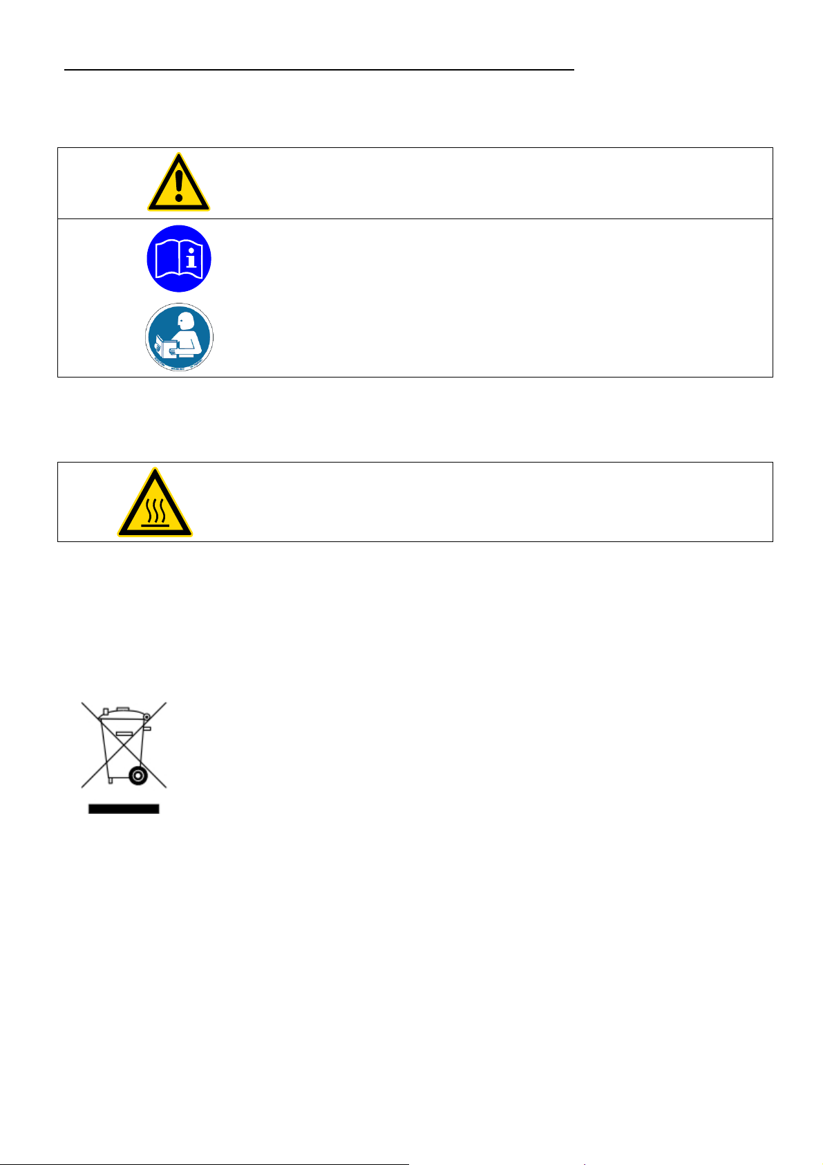
2.1. Disposal
Valid in EU countries
See the current official journal of the European Union – WEEE directive.
Directive of the European Parliament and of the Council on waste electrical
and electronic equipment (WEEE).
This directive requires electrical and electronic equipment marked with a
crossed-out trash can to be disposed of separately in an environmentally
friendly manner.
Contact an authorized waste management company in your country.
Disposal with household waste (unsorted waste) or similar collections of
municipal waste is not permitted!
6
Page 7
2.2. EC Conformity
LC4
The products described in the operating instructions conform to the
requirements of the following European guidelines:
Low voltage regulations with respect to legal harmonization of the member countries
concerning electric devices for use within certain voltage limits.
EMC guideline with respect to legal harmonization of the member countries
concerning electromagnetic compatibility.
JULABO GmbH
Eisenbahnstr. 45
77960 Seelbach / Germany
2.3. Warranty conditions
JULABO GmbH warrants its products against defects in material or in workmanship, when
used under appropriate conditions and in accordance with appropriate operating instructions
Extension of the warranty period – free of charge
for a period of ONE YEAR.
With the ‘1PLUS warranty’ the user receives a free of charge extension to the warranty of up to
24 months, limited to a maximum of 10 000 working hours.
To apply for this extended warranty the user must register the unit on the JULABO web site
www.julabo.de, indicating the serial no. The extended warranty will apply from the date of
JULABO GmbH’s original invoice.
JULABO GmbH reserves the right to decide the validity of any warranty claim. In case of faults
arising either due to faulty materials or workmanship, parts will be repaired or replaced free of
charge, or a new replacement unit will be supplied.
Any other compensation claims are excluded from this guarantee.
7
Page 8

Operator responsibility – Safety recommendations
2.4. Technical specifications
LC4
Adjustable temperature range °C -50 .... 350
Display accuracy % ±0.5 ± 1 Digit
Temperature stability
(depending on substances in the bath)
Temperature selection digital
via keypad indication on MULTI-DISPLAY (LED)
remote control via computer indication on monitor
Temperature display MULTI-DISPLAY (LED): 4-digit
Resolution °C 0.1
ATC function °C ±9.99
Temperature control PID
with 5 parameter sets freely selectable
°C >±0.05
Working temperature: 4-digit
Working temperature sensor Pt100, 4-lead technique
Safety temperature sensor Pt100, 4-lead technique
Electrical connections:
External alarm 24-0 V DC / max. 25 mA
Interface RS232C
Mains power socket
for heating device (at 115 V) W max. 1000; resistive load
or (at 230 V) W max. 2000; resistive load
Overall dimensions (WxDxH) cm 17 x 17 x 16
Weight kg 3
Ambient temperature °C 5 ... 40
Mains power connection ±10% V/Hz 230 / 50-60
Mains power connection ±10% V/Hz 115 / 50-60
Current draw A 10
Total power consumption W max. 1050 (at 115 V)
Total power consumption W max. 2050 (at 230 V)
All measurements have been carried out at
rated voltage and frequency
ambient temperature 20 °C
Technical changes without prior notification reserved.
8
Page 9

Safety installations according to IEC 61010-2-010:
Excess temperature protection 0 °C ... 350 °C
Supplementary safety installations:
Supervision of the working sensor plausibility control
Alarm indication optical + audible (continuous tone)
LC4
Environmental conditions according to EN 61 010, part 1:
Use only indoor.
Altitude up to 2000 m - normal zero.
Ambient temperature: +5 ... +40 °C (for storage and transportation)
Air humidity:
Max. rel. humidity 80 % for temperatures up to +31 °C,
linear decrease down to 50 % relative humidity at a temperature of +40 °C
Max. mains fluctuation of ±10 % are permissible.
Protection class according to EN 60 529 IP31
The unit corresponds to Class I
Overvoltage category II
Pollution degree 2
Caution:
The unit is not for use in explosive environment.
Standards for interference resistance according to EN 61326-1
This unit is an ISM device classified in Group 1 (using high frequency for internal purposes)
Class A (industrial and commercial range).
9
Page 10
Operating instructions
Operating instructions
3. Safety notes for the user
3.1. Explanation of safety notes
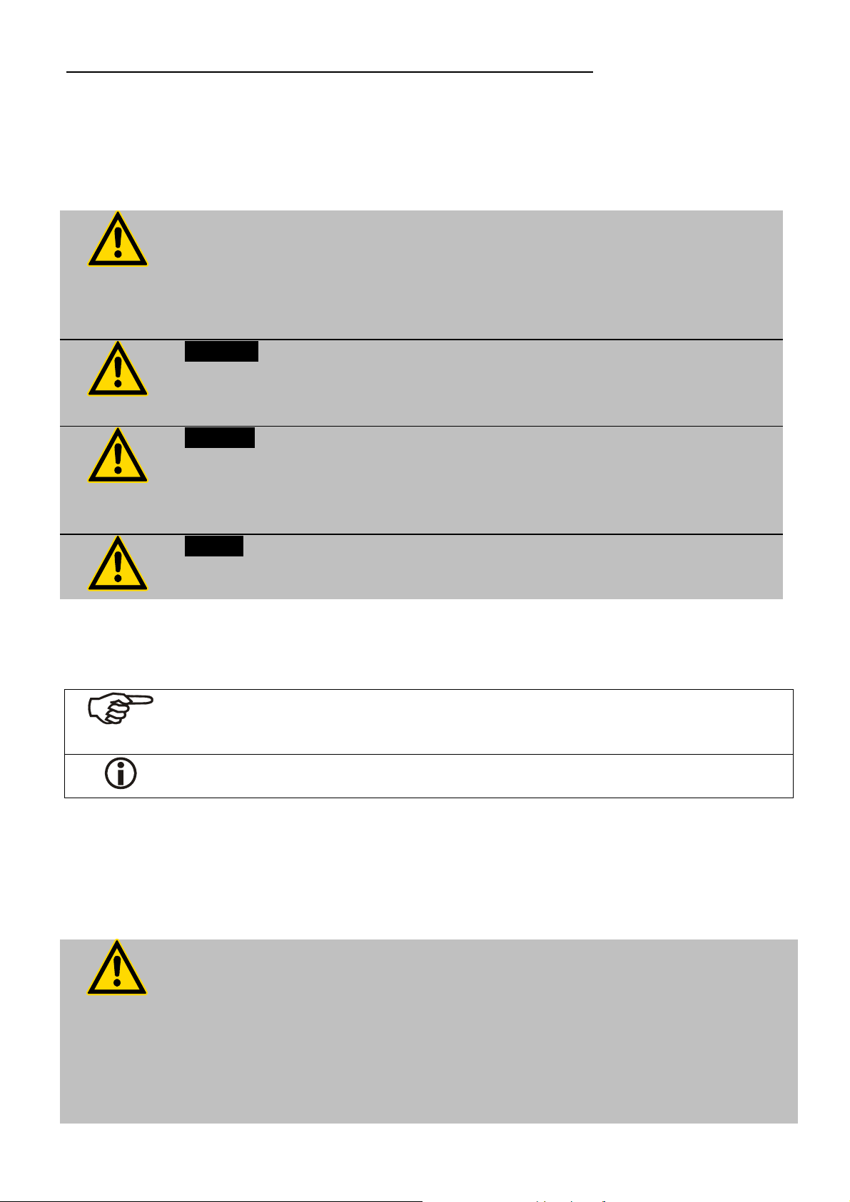
In addition to the safety warnings listed, warnings are posted throughout the
operating manual. These warnings are designated by an exclamation mark
inside an equilateral triangle. “Warning of a dangerous situation (Attention!
Please follow the documentation).”
The danger is classified using a signal word.
Read and follow these important instructions for averting dangers.
Warning:
Describes a possibly highly dangerous situation. If these instructions are not
followed, serious injury and danger to life could result.
Caution:
Describes a possibly dangerous situation. If this is not avoided, slight or
minor injuries could result. A warning of possible property damage may also
be contained in the text.
Notice:
Describes a possibly harmful situation. If this is not avoided, the product or
anything in its surroundings can be damaged.
3.2. Explanation of other notes
Note!
Draws attention to something special.
3.3. Safety recommendations
Follow the safety recommendations to prevent damage to persons or property.
Important!
Indicates usage tips and other useful information.
Further, the valid safety instructions for working places must be followed.
ConnOnly connect the unit to a power socket with earthing contact
(PE – protective earth)!
The power supply plug serves as a safe disconnecting device from the line
and must always be easily accessible.
Place the instrument on an even surface on a pad made of non-inflammable
material.
10
Do not stay in the area below the unit.
Make sure you read and understand all instructions and safety precautions
Page 11

LC4
listed in this manual before installing or operating your unit.
Never operate the unit without bath fluid in the bath.
Observe the flash point of the bath medium used. The excess temperature
protection should be set at least 25 °C below the fire point.
Set up the heating device according to the instructions prior to connection to
the controller and ensure secure attachment to the bath.
Danger of burning and fire!
Immerse both temperature sensors in the bath medium and ensure secure
attachment.
Check the filling level of the bath fluid from time to time. The heater must
always be fully covered with the bath fluid!
Never operate damaged or leaking equipment.
Always turn off the unit and disconnect the mains cable from the power
source before performing any service or maintenance procedures, or before
moving the unit.
Sudden jolts or drops may cause damage in the interior of the unit.
Always empty the bath before moving the unit.
Transport the unit with care.
Never operate equipment with damaged mains power cables.
Observe all warning labels.
Never remove warning labels.
Always turn off the unit and disconnect the mains cable from the power
source before cleaning the unit.
Repairs are to be carried out only by qualified service personnel.
Some parts of the bath cover may become extremely warm during
continuous operation. Therefore, exercise particular caution when touching
these parts. Use safety glasses!
11
Page 12

Operating controls and functional elements
4. Operating controls and functional elements
10
11
12
13
7
6
5
4
3
9
!
1
8
2
14
15
21
16
17
20
19
18
12
Rear view
Page 13

LC4
1
2
3
4
5
6
7
8
9
10
Mains power switch, illuminated
Start / stop key
Working temperature setpoint
Control parameter Tv (lead time)
Control parameter Tn (resetting time)
Control parameter Xp (proportional range)
Safety temperature
Adjustable excess temperature protection(safety temperature)
Indication of working temperature
MULTI-DISPLAY (LED) temperature indication
11
12
13
14
15
16
17
18 Grounded mains socket for heating device
19 Threaded fitting (10 mm) for stand rod attachment
Indicator light - Alarm
Indicator light - Cooling
Indicator light - Heating
Cursors left/right
Edit keys (increase/decrease setting)
Enter key (store)
Connector: Working sensor A
Connector: Safety sensor S
Connector: / alarm output
RS232C interface
20 Mains fuses, fuse holders
21 Mains power cable with plug
13
Page 14
Operating procedures
5. Operating procedures
5.1. Installation
The unit should be set up at a dry location.
5.2. Power connection
Caution:
Only connect the unit to a power socket with earthing contact (PE –
protective earth)!
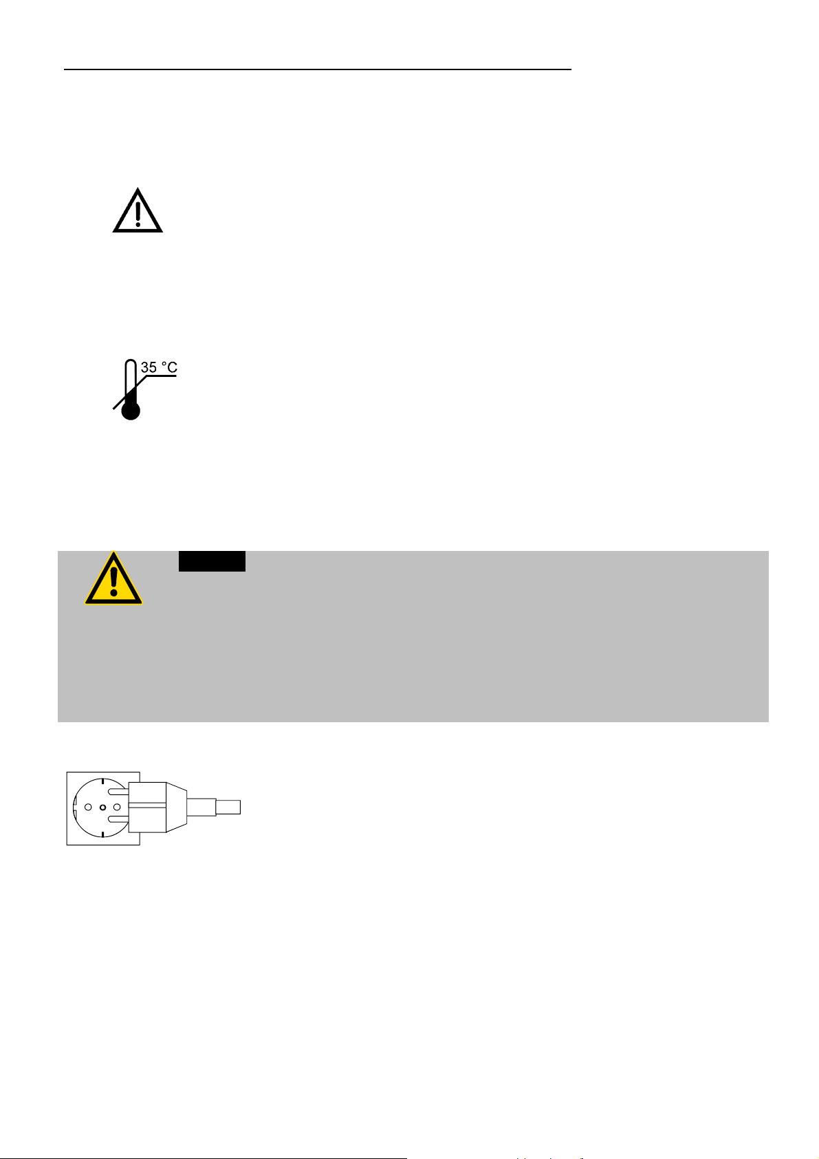
Place the unit in an upright position and do not obstruct the
ventilation.
A wall distance of at least 10 cm must be maintained for
ventilation, allowing internal heat
to be conducted away from the unit.
If one or more temperature controllers are set up in a
cabinet for example, take care of good ventilation (waste
heat per unit = approx. 60 Watts).
The ambient temperature must not exceed 35 °C. Ambient
temperatures above 35 °C result in a failure of the unit.
Do not set up the unit in the immediate vicinity of heat
sources and do not expose to sun light.
The power supply plug serves as safe disconnecting device from the line and
must be always easily accessible.
Never operate equipment with damaged mains power cables.
Regularly check the mains power cables for material defects (e.g. for cracks).
We disclaim all liability for damage caused by incorrect line voltages!
Make sure that the line voltage and frequency match the
supply voltage specified on the type plate.
Deviations of ±10 % are permissible.
14
Page 15

5.3. Connecting a heating device
Caution:
Set up the heating device according to the instructions or securely fix the unit in
the bath tank using appropriate means. Danger of burning and fire!
Connect the power plug to the grounded mains socket (18) on
the rear of the controller.
Caution:
Max. resistive load 1000 W at 115 V / 2000 W at 230 V.
Max. current 5 A at 115 V / 10 A at 230 V.
LC4
5.4. Connecting the temperature sensors
Connect both sensors prior to
alarm shutoff will be effected if the sensors are not connected
(see page 28).
Connect the working sensor to the socket “A” (14) and
the safety sensor to socket “S” (15) .
Sensor calibration:
When the controller is first placed into operation or whenever
Caution:
Place both sensors into the bath medium and securely fix the sensors.
a sensor is replaced, a working sensor calibration must be
carried out (ATC - see page 23).
turning the unit on since an
15
Page 16

Operating procedures
5.5. Applications
Directly heated bath liquid:
The bath liquid is directly heated via the heating device.
Working and safety sensors must both be immersed in the bath liquid.
Whenever countercooling is necessary (in case of temperature application near the
ambient temperature), cooling in the bath is performed through a cooling coil connected to
a solenoid valve and the MVS controller.
!
14
30
15
16a
JULABO MVS
16
15a
18a
18
28
26
25
29
14a
27
14 Connector: Working sensor 14a Working sensor
15 Connector: Safety sensor 15a Safety sensor
16 Connector for control cable 16a Control cable for MVS
18 Mains socket for heating device 18a Heating device / heating hood
25 MVS solenoid valve controller (order no. 9 790 000)
26 Solenoid valve 220 Volts (order no. 8 980 700)
27 Cooling coil
28 Tap water connection
29 Cooling water drain
30 Stirrer motor for bath circulation
31 Bath tank / round bottom flask with bath liquid
31
16
Page 17

Indirectly heated bath liquid:
The bath liquid is indirectly heated.
Working and safety sensors must both be immersed in the bath liquid.
!
LC4
14
14a
30
15
15a
18
31
18a
5.6. Switching on / Start - Stop
Switching on:
Turn on the mains power switch.
The unit performs a self-test. A signal sounds, and all
segments of the two 4-digit displays as well as all indicator
lights will illuminate.
Then the software version (example: n 1.0) and the model
description "LC 4" appear.
17
Page 18

Operating procedures
The display "OFF" or "r OFF" indicates the controller is ready to
operate. Also the effective working temperature setpoint is
indicated
(example: 20.0 °C).
The controller enters the operating mode activated before
switching the controller off,
keypad control mode (manual operation) or
remote control mode (operation via personal computer).
Start:
Press the start/stop key.
- The MULTI-DISPLAY (LED) indicates the actual bath
temperature. (example: 21.0 °C)
- The indicator light in the setpoint key illuminates.
Temperature control is carried out according to the parameter
set last effective (see page 24).
Stop:
Press the start/stop key.
The MULTI-DISPLAY (LED) indicates the message "OFF".
The unit also enters the safe operating state "OFF" or "r OFF"
after a mains power interruptance. The temperature values
entered via the keypad remain in memory. With the controller
in keypad control mode, press the start/stop key to restart
operation.
With the controller in remote control mode, the personal
computer must first resend the parameters set via the interface
before operation of the controller may be restarted.
18
Page 19

5.7. Setting the temperatures
LC4
Setting the working temperature:
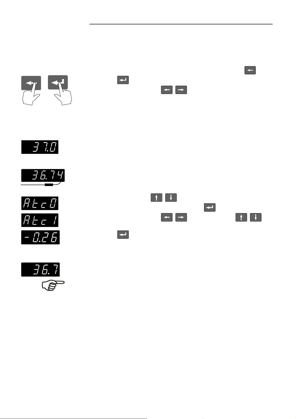
1. Press the setpoint key .
The indicator light blinks and the effective value appears
on the MULTI-DISPLAY (LED).
2. Use the cursor keys to move left or right on the
display until the numeral you wish to change is blinking.
3. Use the increase/decrease arrows to change the
selected numeral (-, 0, 1, 2, 3, ... 9).
4. Press enter to store the selected value (example: 37.0
°C).
The working temperature is maintained constant after a short
heat-up time (example: 37.0 °C).
5.8. Setting the PID control parameters Xp, Tn and Tv
Setting the Xp (proportional range)
1. Press the key .
The indicator light blinks and the effective Xp value
appears on the MULTI-DISPLAY (LED).
2. Use the cursor keys to move left or right on the
display until the numeral you wish to change is blinking.
3. Use the increase/decrease arrows to change
the selected numeral (-, 0, 1, 2, 3, ... 9).
4. Press enter to store the selected value (example: 12
°C).
Setting range for the Xp parameter: 0.1 to 50 °C
19
Page 20

Operating procedures
Setting the Tn (resetting time)
1. Press the key .
The indicator light blinks and the effective value for Tn
appears on the MULTI-DISPLAY (LED).
2. Follow the instructions
3. for
4. (example: 1200 s).
Setting range for Tn: 1 to 9998 s.
With Tn set to 9999, the integral part of the controller is
deactivated (use of a P or PD type controller).
Setting the Tv (lead time)
1. Press the key .
The indicator light blinks and the effective value for Tv
appears on the MULTI-DISPLAY (LED).
2. Follow the instructions
3. for
4. (example: 120 s).
Setting range for Tv: 0 to 1000 s.
With Tv set to 0 eingestellt, the differential part of the
controller is deactivated (use of a P or PI type controller).
20
Page 21

5.8.1. Optimization instructions for the PID control parameters
The heat-up curve reveals inappropriate control settings.
°C
optimum setting
t
Inappropriate settings may produce the following heatup curves:
°C
Xp too low
LC4
°C
°C
°C
t
Tv/Tn too low
t
Xp or Tv too high
t
Tv/Tn or Xp too high
t
21
Page 22

Operating procedures
5.9. Setting the safety temperature (with shutdown function)
!
+
(excess temperature protection)
Press the key to indicate the safety temperature value on
the MULTI-DISPLAY and using a screwdriver
simultaneously turn the setting screw to the desired
value (example: 50 °C).
Setting range: 0 °C to 360 °C
in 2 °C steps
This safety installation is independent of the control circuit.
As soon as this safety installation is triggered, a complete
The excess temperature protection should be set at least 25 °C below the fire
point of the bath liquid used!
In the event of wrong setting there is a fire hazard!
We disclaim all liability for damage caused by wrong settings!
shutdown of the connected heating device is effected.
The alarm is indicated by optical and audible signals
(continuous tone)
and
on the MULTI-DISPLAY (LED) appears the error message
"Error 01".
Recommendation:
Set the safety temperature at 5 to 10 °C above the working
temperature setpoint.
22
Page 23
6. Menu functions
LC4
6.1. Sensor calibration - ATC function
Controller (TT)
Calibration bath (TM)
Parameters and values are set via the menu level that may be
selected at any time.
Enter or exit the menu level by pressing the left arrow and
enter at the same time.
Using the cursor keys select the menu functions one
by one.
The ATC (Absolute Temperature Calibration) function serves to
calibrate the working sensor.
Place the working sensor "A" and the temperature sensor of a
thermometer in the calibration bath.
Determine the difference temperature (∆T=TM - TT)
and store as correcting factor (example ∆T = -0.26 °C) as
follows:
With the edit keys
"Atc 0" to "Atc 1" and then press enter .
Using the cursor keys and the edit keys
set the correcting factor (example -0.26 °C) and then press
enter .
After exiting the menu level, the corrected value (example: 36.7
°C) is indicated on the MULTI-DISPLAY (LED).
Recommendation:
In case a calibrated temperature measuring instrument is used, the
ATC function allows the controller to be used as testing instrument
according to ISO 9000.
change the menu function from
23
Page 24

Menu functions
6.2. Temperature range: HL / LL
The laboratory controller LC4 features the possibility to limit the
working temperature range to protect thermally sensitive
substances.
Setting the upper limit
With the edit keys change the menu function from
6.3. Parameter sets for control: PA
“HL 0” to "HL 1" and then press enter .
Using the cursor keys and the edit keys set
the upper limit (example: 250.0 °C) and then press enter .
HL (High Limit) factory-setting: 350.0 °C
Setting the lower limit
With the edit keys
0” to "LL 1" and then press enter .
Using the cursor keys and the edit keys set
the lower limit (example: -40.0 °C) and then press enter .
LL (Low Limit) factory-setting: -50.0 °C
The LC4 provides 5 different parameter sets for controlled
processes.
Selecting a parameter set for control:
Press the edit keys to select the desired parameter
set (1 to 5) and then press enter .
(example: parameter set 3).
change the menu function from “LL
24
Page 25

Set 1: Xp = 4 °C
Set 2 Xp = 10 °C
Set 3 Xp = 20 °C
Set 4 Xp = 35 °C
Set 5 Xp = 15 °C
Tn = 150 s
Tv = 10 s
Tn = 300 s
Tv = 25 s
Tn = 1800 s
Tv = 165 s
Tn = 1800 s
Tv = 130 s
Tn = 1550 s
Tv = 120 s
LC4
For each parameter set, the control parameters Xp, Tn and Tv
may be individually modified and stored (see page 19).
Preference:
Quick access to parameters determined during previous
applications.
Factory-preset parameter sets for the following
controlled processes:
Directly heated liquid bath
Filling volume: 4.5 litres of water
Setpoint temperature: 70 °C
Heater capacity: 2000 W
Directly heated liquid bath
Filling volume: 4 litres of Thermal H
Setpoint temperature: 150 °C
Heater capacity: 2000 W
Heating hood model JH2000 with 2000 ml round bottom
flask
Filling volume: 2 litres of water
Setpoint temperature: 70 °C
Heater capacity: 480 W (stage III)
Heating hood JM500 with 500 ml round bottom flask
Filling volume: 0.5 litres of water
Setpoint temperature: 70 °C
Heater capacity: 150 W (stage II)
Heating hood JM500 with 500 ml round bottom flask
Filling volume: 0.5 litres of Thermal H
Setpoint temperature: 100 °C
Heater capacity: 150 W (stage II)
25
Page 26

Menu functions
6.4. Active countercooling: Pc
6.5. Controlling the heater capacity: h
For applications near the ambient temperature, countercooling
might become necessary.
For this purpose, connect the JULABO MVS solenoid valve
controller to the / alarm socket (application example see page
16). The supply of a cooling pulse "Pc" must be activated on the
controller.
Activating the supply of a cooling pulse:
With the edit keys change the menu function from
“Pc 0” to "Pc 1" and then press enter .
Factory setting: "Pc 0" (no countercooling).
Whenever countercooling is not necessary, reset the “Pc”
parameter to 0.
This control allows the maximum effective heater capacity of the
connected heating device to be adjusted in 10 % steps between 10
% and 100 %. The gradient of the temperature rise function may
thus be controlled to permit gentle warming of thermally sensitive
substances and to prevent over-shooting.
Controlling the heater capacity:
Using the edit keys
capacity and then press enter .
(example: 70 %).
Factory setting: 100 %
set the desired maximum heater
26
Page 27

6.6. Interface parameters: r - br - P - H
LC4
RS232C
Whenever the parameter setting of the controller is not conform to
those of the connected personal computer, a modification is
necessary.
Factory setting of the RS232 interface:
Baudrate: 4800 Bauds
Parity: 2 (even)
Handshake: 1 (Hardware handshake)
Data bits: 7
Stop bits: 1
Press the cursor key until the desired parameter appears on
the MULTI-DISPLAY (LED).
Use the edit keys to set the desired parameter and
then press enter .
Adjustable interface parameters
REMOTE 0 = keypad control mode
1 = remote control mode via RS232C
BAUDRATE 12 = 1200 bauds
24 = 2400 bauds
48 = 4800 bauds
96 = 9600 bauds
PARITY 0 = no parity
1 = odd
2 = even
HANDSHAKE
0 = Protocol Xon/Xoff (software handshake)
1 = Protocol RTS/CTS (hardware handshake)
Like all parametes which can be entered through the keypad,
interface parameters are stored in memory even after the controller
is turned off.
27
Page 28

Troubleshooting guide / Error messages
7. Troubleshooting guide / Error messages
!
+
Cause Remedy
A sudden temperature increase,
Whenever the microprocessor electronics registers a failure, a
complete shutdown of the heating device connected to the controller
is performed. The alarm light " " illuminates and a continuous
signal tone sounds.
Press enter to turn off the signal tone.
The safety temperature value lies
below the working temperature
setpoint.
e.g. caused by the immersion of
preheated samples.
After eliminating the malfunction, press the mains power switch off
and on again to cancel the alarm state.
The wires of the working temperature sensor are interrupted or
short-circuited.
Set the safety temperature to
a higher value.
Set the safety temperature to
a higher value.
Warning:
Before exchanging the fuses, turn off the mains power switch and disconnect
the power plug from the mains socket!
Use only fine fuses with the specified nominal value.
other errors
After eliminating the malfunction, press the mains power switch off
and on again to cancel the alarm state.
If the error reappears, contact an authorized JULABO service station.
If necessary have the unit checked by a JULABO service technician.
Mains fuses
The mains fuses on the rear of the unit may easily be
exchanged as shown on the left.
(Fine fuse T 10.0 A, dia. 5 x 20 mm)
28
Page 29

S
g
8. Electrical connections
Grounded mains socket
Connector for heating device
Maximum 1000 W resistive load at 115 V.
Maximum current 5 A.
Maximum 2000 W resistive load at 230 V.
Maximum current 10 A.
Notice:
LC4
2
3
Pt100
1
4
hield Plug
Use shielded cables only.
The shield of the connecting cable is electrically connected to the plug
housing.
Connectors for temperature sensors
Pin assignment:
Pin 1 Current +
Pin 2 Voltage +
Pin 3 Voltage -
2
3
Look on
solderin
1
4
side.
Pin 4 Current -
/ ALARM - connector
The "
messages.
ALARM" connector may be used as output for alarm
Circuit: Operation = relay powered
Alarm = relay not powered
Pin assignment:
Pin 1: +24 V (max. current 25 mA)
Pin 2: 0 V
Pin 3: 0 V / alarm relay
Pin 4: Reserved - do not use!
Pin 5: Cooling pulse
29
Page 30

Electrical connections
9
5
1
6
RS232C
Accessories: Order No. Description
RS232C serial interface
This port can be used to connect a computer with an RS232C
cable for remote control of the controller.
RS232 serial interface
This port can be used to connect a computer with an RS232 cable
for remote control of the circulator.
Pin assignments RS232:
Pin 2 RxD Receive Data
Pin 3 TxD Transmit Data
Pin 5 0 V Signal GND
Pin 7 RTS Request to send
Pin 8 CTS Clear to send
Pin 1; 4; 6, 9 Reserved - do not use!
RS232 interface cable
Circulator (9-pol) PC (9-pol)
Pin 2 RxD Pin 3 TxD
Pin 3 TxD Pin 2 RxD
Pin 5 GND Pin 5 GND
Pin 7 RTS Pin 8 CTS
Pin 8 CTS Pin 7 RTS
8 980 073 RS232 interface cable 9-pol./9-pol. , 2,5 m
8 900 110 USB interface adapter cable
30
Page 31

9. Remote control
9.1. Communication with a PC or a superordinated data system
Suitable terminal programs for communicating with a PC are:
MS-Windows - TERMINAL.EXE (included with MS-Windows).
If the controller is put into remote control mode via the configuration
level, the display will read "r OFF" = REMOTE STOP. The controller is
now operated via the computer.
In general, the computer (master) sends commands to the controller
(slave). The controller sends data (including error messages) only
when the computer asks for it.
A transfer sequence consists of:
Command
space (; Hex: 20)
LC4
parameter (the character separating decimals in a
group is the period) End of file (; Hex: 0D)
The commands are divided into in and out commands.
in commands: asking for parameters to be displayed
out commands: setting parameters
The out commands are valid only in remote control mode.
Examples:
Command to set the working temperature to 55.5 °C:
out_sp_00 55.5
Command to ask for the working temperature:
in_sp_00
Response from the controller:
55.5
31
Page 32

Remote control
9.2. List of commands
Befehl Parameter Description
version none Number of software version (V X.xx)
status none Status message, error message (see page 34)
out_mode_05 0 Stop the controller = r OFF
out_mode_05 1 Start the controller
out_mode_02 1 Parameter set 1 effective for control
out_mode_02 2 Parameter set 2 effective for control
out_mode_02 3 Parameter set 3 effective for control
out_mode_02 4 Parameter set 4 effective for control
out_mode_02 5 Parameter set 5 effective for control
in_mode_02 none Ask for effective parameter set
out_sp_00 xxx.x Set working temperature
in_sp_00 none Ask for working temperature
in_pv_00 none Ask for effective value registered by working sensor
in_pv_01 none Ask for effective heater capacity
out_par_00 xxx.x Set Xp of parameter set 1
in_par_00 none Ask for Xp of parameter set 1
out_par_01 xxx.x Set Tn of parameter set 1
in_par_01 none Ask for Tn of parameter set 1
out_par_02 xxxx.x Set Tv of parameter set 1
in_par_02 none Ask for Tv of parameter set 1
out_par_03 xxx.x Set Xp of parameter set 2
in_par_03 none Ask for Xp of parameter set 2
32
Page 33

Command Parameter Description
out_par_04 xxx.x Set Tn of parameter set 2
in_par_04 none Ask for Tn of parameter set 2
out_par_05 xxxx.x Set Tv of parameter set 2
in_par_05 none Ask for Tv of parameter set 2
out_par_06 xxx.x Set Xp of parameter set 3
in_par_06 none Ask for Xp of parameter set 3
out_par_07 xxx.x Set Tn of parameter set 3
in_par_07 none Ask for Tn of parameter set 3
out_par_08 xxxx.x Set Tv of parameter set 3
LC4
in_par_08 none Ask for Tv of parameter set 3
out_par_09 xxx.x Set Xp of parameter set 4
in_par_09 none Ask for Xp of parameter set 4
out_par_10 xxx.x Set Tn of parameter set 4
in_par_10 none Ask for Tn of parameter set 4
out_par_11 xxxx.x Set Tv of parameter set 4
in_par_11 none Ask for Tv of parameter set 4
out_par_12 xxx.x Set Xp of parameter set 5
in_par_12 none Ask for Xp of parameter set 5
out_par_13 xxxx.x Set Tn of parameter set 5
in_par_13 none Ask for Tn of parameter set 5
out_par_14 xxxx.x Set Tv of parameter set 5
in_par_14 none Ask for Tv of parameter set 5
33
Page 34

Remote control
9.3. Status messages
Message Description
00 MANUAL STOP Controller in "OFF" state
01 MANUAL START Controller in keypad control mode
02 REMOTE STOP Controller in "r OFF" state
03 REMOTE START Controller in remote control mode
9.4. Error messages
Message
-01 SAFETY-TEMP ALARM
-05 TEMPERATURE MEASUREMENT
ALARM
-07 I2C-BUS WRITE ERROR
-07 I2C-BUS READ ERROR
-07 I2C-BUS READ/WRITE ERROR
-08 INVALID COMMAND
-10 VALUE TOO SMALL
-11 VALUE TOO LARGE
-12 VALUE NOT VALID
-13 COMMAND NOT ALLOWED IN
CURRENT OPERATING MODE
Description
Safety temperature alarm
Error in measuring system.
Internal errors
Invalid command
Entered value too small
Entered value too large
Value not valid
Invalid command in current operating mode
34
Page 35

10. Cleaning / repairing the unit
Caution:
Improper maintenance or repair can result in electric shock or damage to the
unit.
Repairs and any other work are to be carried out only by qualified service
Always turn off the unit and disconnect the mains cable from the power
Prevent humidity from entering into the water bath.
Cleaning:
personnel authorized by JULABO.
source before performing any service or maintenance procedures, or
before moving the unit.
The controller is designed for continuous operation under normal
conditions. Periodic maintenance is not required.
Clean the outside of the unit using a wet cloth and low surface
tension water.
LC4
Repairs:
Returning a unit:
Before asking for a service technician or returning a JULABO
instrument for repair, please contact an authorized JULABO service
station.
When returning the unit:
Clean the unit and, if necessary, decontaminate the unit in order
to avoid endangering service personnel.
Attach a short fault description.
During transport the unit has to stand upright. Mark the packing
correspondingly.
When returning a unit, take care of careful and adequate
packing.
JULABO is not responsible for damages that might occur from
insufficient packing.
JULABO reserves the right to carry out technical modifications with
repairs for providing improved performance of a unit.
35
 Loading...