

Page 1
40033638
No.E368-00
ENGINEER’S MANUAL
HIGH SPEED SEMI-DRY HEAD OVERLOCK/INTERLOCK/
SEWING MACHINE
MO-6700D Series
®
Page 2

PREFACE
This Engineer’s Manual is written for the technical personnel who are responsible for the service and maintenance
of the machine.
The Instruction Manual for these machines intended for the maintenance personnel and operators at an apparel
factory contains operating instructions in detail. And this manual describes “Standard Adjustment”, “Adjustment
Procedures”, “Results of Improper Adjustment”, and other important information which are not covered by the
Instruction Manual.
It is advisable to use the relevant Instruction Manual and Parts List together with this Engineer’s Manual when
carrying out the maintenance of these machines.
In addition, for the motor for the sewing machine with thread trimmer, refer to the separate Instruction Manual or
Engineer’s Manual for the motor. And for the control panel, refer to the Instruction Manual for the control panel.
This manual gives the “Standard Adjustment” on the former page under which the most basic adjustment value is
described, and on the latter page “Results of Improper Adjustment” under which stitching errors and troubles
arising from mechanical failures are described together with the “Adjustment Procedures”.
Page 3

CONTENTS
1. SPECIFICATIONS.......................................................................................... 1
(1) MO-6700D SERIES ......................................................................................................1
2. MODEL NUMBERING SYSTEM.................................................................... 2
3. ST ANDARD ADJUSTMENT .......................................................................... 4
(1) Adjusting the needle height.......................................................................................4
(2) Positioning the throat plate .......................................................................................4
(3) Installing position of the needle clamp ....................................................................6
(4) Adjusting the length of the lower looper holder
(Applicable only to MO-6716D series) ......................................................................6
(5) Adjusting the lower looper ........................................................................................8
1) Returning amount of the lower looper ..................................................................................................8
2) Clearance between the lower looper and the needle...........................................................................8
(6) Position of the upper looper guide .........................................................................10
(7) Positioning the upper looper holder.......................................................................12
(8) Positioning the upper looper...................................................................................14
1) Height of the upper looper..................................................................................................................14
2) Longitudinal position of the upper looper ...........................................................................................14
(9) Adjusting the double chain looper (Applicable only to MO-6716D series) .........16
1) Returning amount of the double chain looper ....................................................................................16
2) Longitudinal motion (Avoid motion)....................................................................................................16
3) Clearance between the double chain looper and the needle .............................................................16
(10) Adjusting the height and clearance of the needle guard......................................18
1) For 1-needle or 2-needle overlock machine.......................................................................................18
2) For safely stitch machine ...................................................................................................................18
(11) Adjusting the height of the feed dog ......................................................................20
(12) Adjusting the tilt of the feed dog.............................................................................20
(13) Adjusting the differential feed ratio ........................................................................22
(14) Longitudinal position of the feed dog ....................................................................22
(15) Adjusting the presser foot.......................................................................................24
1) Adjusting the tilt of the presser foo....................................................................................................24
2) Adjusting the micro-lifting mechanism of the presser foot.................................................................24
(16) Positioning the upper knife arm shaft ....................................................................26
(17) Positioning the upper and lower knives, and available overedge widths...........26
1) Lower knife.........................................................................................................................................26
2) Upper knife.........................................................................................................................................26
3) Overdging width .................................................................................................................................26
(18) Resharpening of the knife........................................................................................28
(19) Position of the thread cam (Applicable only to MO-6716D series) ......................28
1) Adjustment of the thread cam ............................................................................................................28
2) Adjusting looper thread cam thread guides A and B and the looper thread cam nail.........................28
3) Adjusting looper thread auxiliary thread take-up lever (Exclusive for 30P)........................................30
(20) Adjusting the throat plate support..........................................................................32
(21) Adjusting the feed mechanism cover presser.......................................................32
(22) Adjusting the looper cover ......................................................................................34
(23) Adjusting the cloth chip cover ................................................................................34
(24) Position of the thread guides and the looper thread take-ups.............................36
Page 4

(25) Adjusting soft chain making mechanism...............................................................38
1) Replacing the parts with those exclusively designed for making soft chains .....................................38
2) Adjustment value................................................................................................................................38
3) Important points in adjustment ...........................................................................................................39
4. ADDITIONAL INFORMATION AND PRECAUTIONS.................................. 40
(1) Thread tension............................................................................................................40
1) Strength of tension spring ..................................................................................................................40
2) Springs used for each model .............................................................................................................40
(2) Upper looper .............................................................................................................40
(3) Center-to-center distance of the upper looper holder ..........................................41
(4) Caution in assembly.................................................................................................41
1) Application of sealant .........................................................................................................................41
2) Precautions to be taken with respect to the lubricating components .................................................43
3) Applying the exclusive grease............................................................................................................44
(5) Kinds of motor pulleys, belts and frame support plate bolts...............................46
1) Motor pulleys and belts ......................................................................................................................46
2) Pat No. of frame support plate bolt ....................................................................................................46
5. ADJUSTMENT VALUES OF THE NEEDLE HEIGHT
AND LOOPER TIMING ................................................................................ 47
(1) MO-6700D SERIES ....................................................................................................47
6. TROUBLES AND CORRECTIVE MEASURES ........................................... 48
7. DIMENSIONS OF TABLE ............................................................................ 60
(1) Semi-sunken type .....................................................................................................60
(2) Semi-sunken type (synchronizer is used)..............................................................61
(3) Fully-sunken type .....................................................................................................62
Page 5

– 1 –
1. SPECIFICATIONS
(1) MO-6700D SERIES
No. Item Specifications
1 Model MO-6704D MO-6714D MO-6716D
2 Description 1-needle Overlock 2-needle Overlock 2-needle Safety stitch
machine machine machine
3 Stitch type F. S. T. JIS E13 JIS E24 JIS E13+D12
(USA standard : 504) (USA standard : 514) (USA standard : 516)
4 Sewing speed 6000rpm
5 Stitch length 0.8 to 4mm 1.5 to 4mm
6Needle gauge 2.0, 3.2mm 3.2, 4.8mm
7Overedging width 1.6, 3.2, 4, 4.8mm 2.0, 3.2, 4mm 3.2, 4, 4.8, 6.4mm
8 Differential feed ratio Gathering 1 : 2 (Max.1 : 4), Stretching 1 : 0.7 (Max.1 : 0.6)
9 Needle bar stroke 24.5 mm (30P for light to medium-weight materials),
25.5 mm (40H for medium to heavy-weight materials)
10 Needle tilt angle 20°
11
Needle bar mechanism
Upper and lower needle bar bushing type
12 Needle ORGAN DC X 27 (Standard) (DC X 1 can be used as well.)
13 Presser lifting amount 7.0mm 6.5mm 7.0mm
14 Presser foot pressure 49N (5kg)
15
Stitch adjusting method
By pushbutton
16 Upper knife Flat knife
17
Differential feed adjustment
By lever with micro adjustment mechanism
18 Weight 28kg
19 Lubrication Automatic geared lubrication system and grease charge
20 Lubricating oil JUKI MACHINE OIL 18 (Equivalent to ISO VG 18) Product No.: MML018900CA
21 Grease Exclusive grease (Part No. 23640204)
22 Needle cooler Optional
23 Needle thread cooler Optional
24
Micro presser lifting device
Provided as standard
25 Motor 2P 400W
*1. Grease should be supplied to the needle bar system and upper looper system.
Page 6
– 2 –
2. MODEL NUMBERING SYSTEM
MO-6700D SERIES MODEL NUMBERING SYSTEM
1 2345678910111213 14 15 16 17 18 19 20 21 22 23 24 25 26
MO67 D /
3 to 6 Model classification
6704 1-needle 3-thread overlock
6705 Blind-hemming
6712 2-needle, 4-thread imitation safety stitch
6714 2-needle 4-thread overlock
6716 2-needle 5-thread safety stitch
6743 3-needle 6-thread safety stitch
6745 2-needle double chain stitch
7Type classification
D Semi-dry head
8 Needle gauge classification
0 1-needle
B 2.0mm
D 3.2mm
F 4.8mm
1 4.8+2.0mm
2 3.2+2.0mm
9 Overedging width classification
A 1.6mm
B 2.0mm
D 3.2mm
E 4.0mm
F 4.8mm
H 6.4mm
10 Feed dog classification
42-row
51-row
63-row
11 Material classification
(classification applied to handling material and cloth)
1 Extra light- to right-weight material Light weight material such as dress shirt
2
3Light- to medium-weight materials General fabrics
4 Meduim- to heavy-weight materials Exclusive for knit such as sweater
5Medium weight material such as denim to heavy weight material
12 Application classification
(classification of application based on work and process)
0 Standard
1 For blind hemming
2 For ruffling
4 For tape attaching
5 For rolled hemming
6 For tape feeding
*
*
The asterisk (*) indicates 3-needle type.
Page 7

– 3 –
13 Special machine classification
(special classification of machine,
structure and specs. other than gauge set)
0 Standard
7 Upper looper high throw
F Swim suits
H Upper looper extra high lift
P Puckering prevention
15 to 22 Device and attachment classfication
G39/Q141 Presser for tape attaching (for sharp curve)/tape guide
L121 Blind stitch hemming attachment
S159 Swing-type gathering device (interlocked with pedal, for safety stitch machine)
S162 Swing-type gathering device (manual lever operated, for overlock machine)
N077 Clean finish top and bottom
E35 Overedging lug replace type throat plate
24 Place of destination
A Standard
DU.S.A and Japan
G China (in China)
25 Accessories type
A Standard
B Eouropa and U.S.A
G China (in China)
26 Table type
0 Fully sunken type
1 Semi sunken type
Page 8
– 4 –
Model
DimensionADimensionBDimension
C
MO-6704D-0A -150 10.5 — —
MO-6705D-0 -210 10.5 — —
MO-6704D-0 -300 10.5 — —
MO-6704D-0 -307 10.5 — —
MO-6704D-0 -40H 11.3 — —
MO-6704D-0F6-50H 11.3 — —
MO-6714D-B - 7 10.5 9.1 —
MO-6714D-B - H 11.3 9.9 —
MO-6712D-DF6-50 11.0 9.4 —
MO-6714D-B -30P 10.5 9.1 —
MO-6716D- -300 10.5 — 9.8
MO-6716D-FF6-307 10.5 — 9.8
MO-6716D- - 11.3 — 10.6
MO-6716D- -30P 10.5 — 9.8
A
B
10
°
6704D
6705D
6712D
6714D
6716D
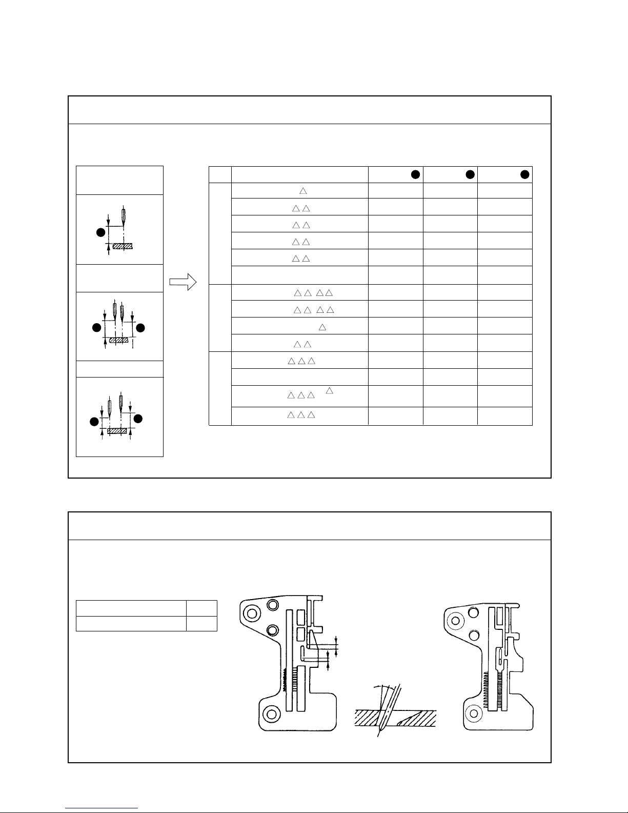
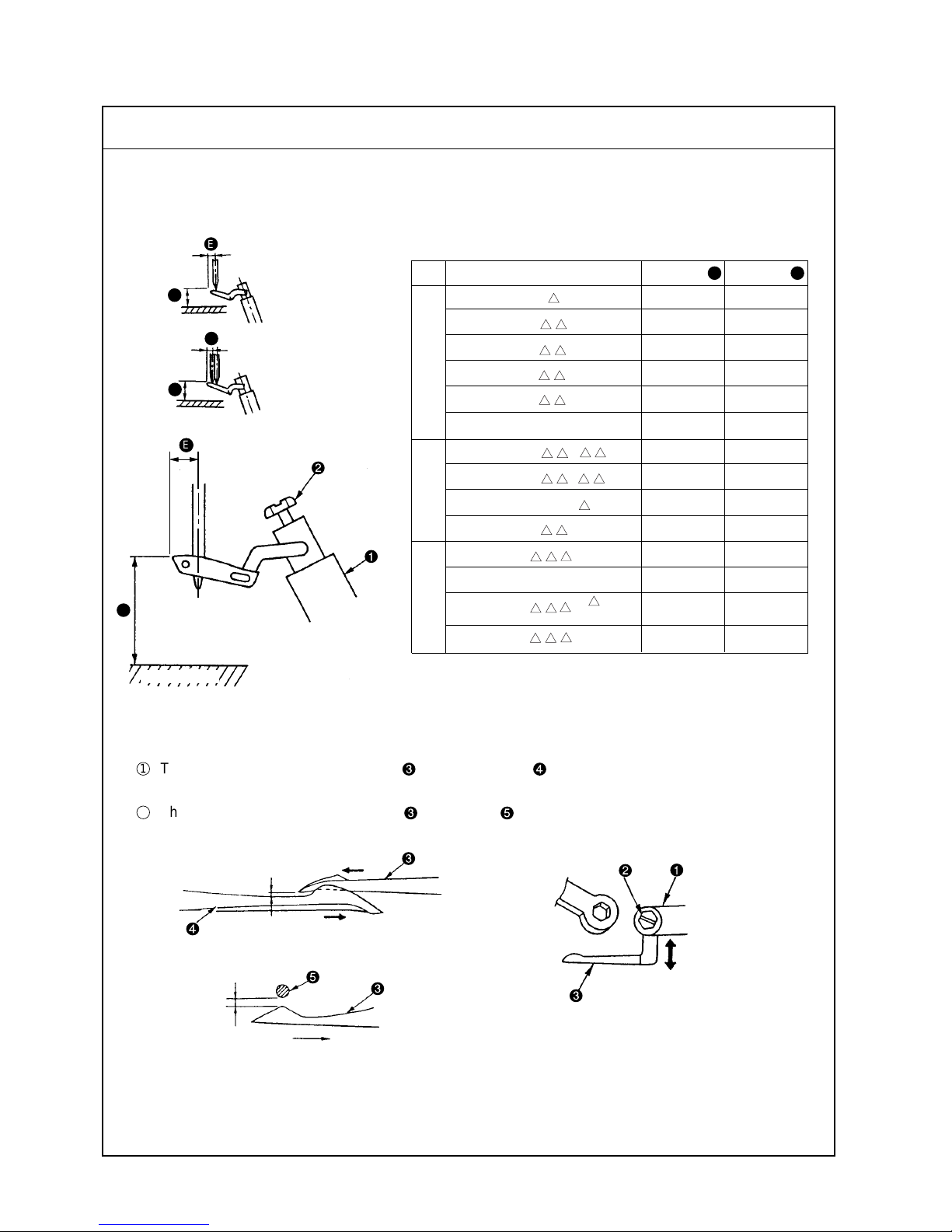
When the needle(s) is in the highest position, the needle height from the throat plate surface should be as
shown below.
3. STANDARD ADJUSTMENT
(1) Adjusting the needle height
The needle entry point should be such that the distances listed below are provided between the needle slot
edge of the throat plate and the center of needle.
(2) Positioning the throat plate
(Unit : mm)
The adjustment of needle height for the 2-needle overlock machine should be
made in reference to the left needle.
(Unit : mm)
Overlock side A 1.3
Double-chainstitch side B 1.0
For 30P
(Safety stitch machine)
4 H
50H
A
A
B
C
A
Standard Adjustment
Standard Adjustment
1-needle overlock
machine
2-needle overlock
machine
Safety stitch
machine
Page 9
– 5 –
Needle driving shaft
1) Take off the upper cover, loosen setscrew of needle driving forked
crank and move needle driving forked crank up or down to adjust
the needle height.
(Caution) Do not fully loosen the setscrew of the needle driving
forked crank .
If the needle driving forked crank has got out of position
laterally when its setscrew was loosened, fully loosen the
setscrew and turn pulley to allow the forked crank to turn
until it settles by itself. Then tighten the setscrew to fix
the forked crank at that position.
o Any other needle height than
specified here will badly affect the
action of the lower looper, the
timing for catching the upper
looper thread, etc.
o Improper lateral position of the
needle driving forked crank will
cause seizure, play, or other
troubles.
o Improperly positioned throat plate
with cause needle breakage,
contact of the needles will the
throat plate, or other troubles.
1) Loosen setscrews of throat plate base and move throat plate
base back and forth to adjust dimension A or B.
Adjustment Procedure Results of Improper Adjustment
Adjustment Procedure Results of Improper Adjustment
Page 10
– 6 –
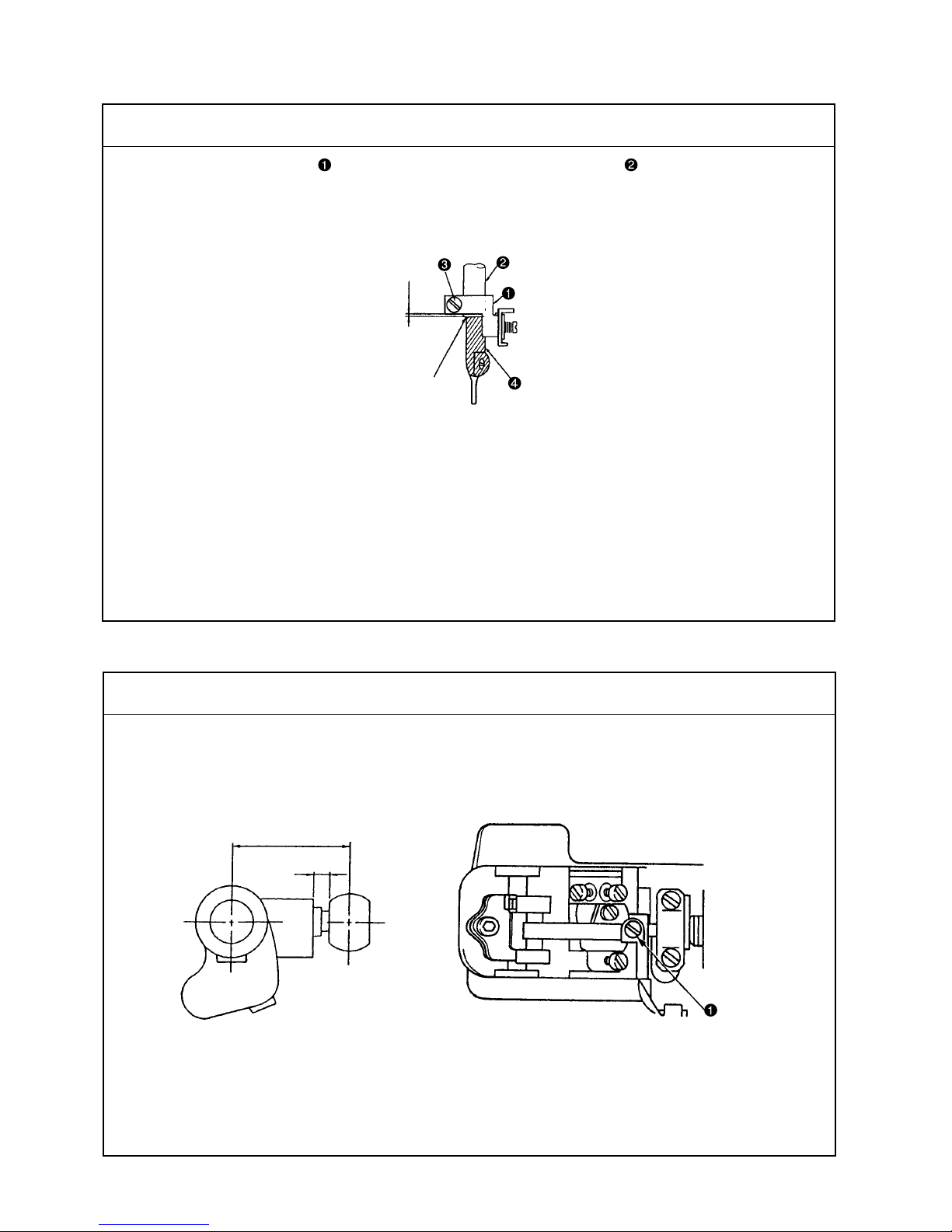
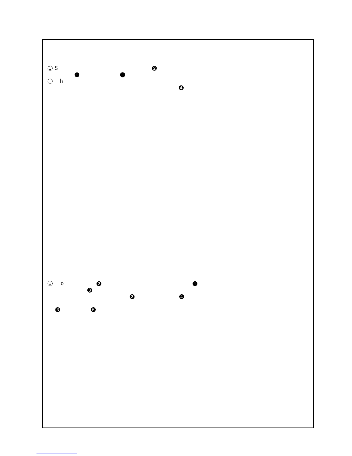
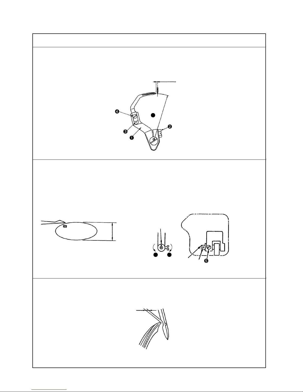
(3) Installing position of the needle clamp
Needle clamp connecting stud should fit with the bottom end of needle bar or be spaced within 0 to 0.5
mm.
(4) Adjusting the length of the lower looper holder (Applicable only to MO-6716D series)
The center-to-center distance should be 26 mm.
At this time, the clearance between the end surface of the arm and the neck of the ball should be 3.5mm.
26mm
3.5mm
Butt the needle clamp with the
bottom end of the needle bar.
0 to 0.5mm
Standard Adjustment
Standard Adjustment
Page 11
– 7 –
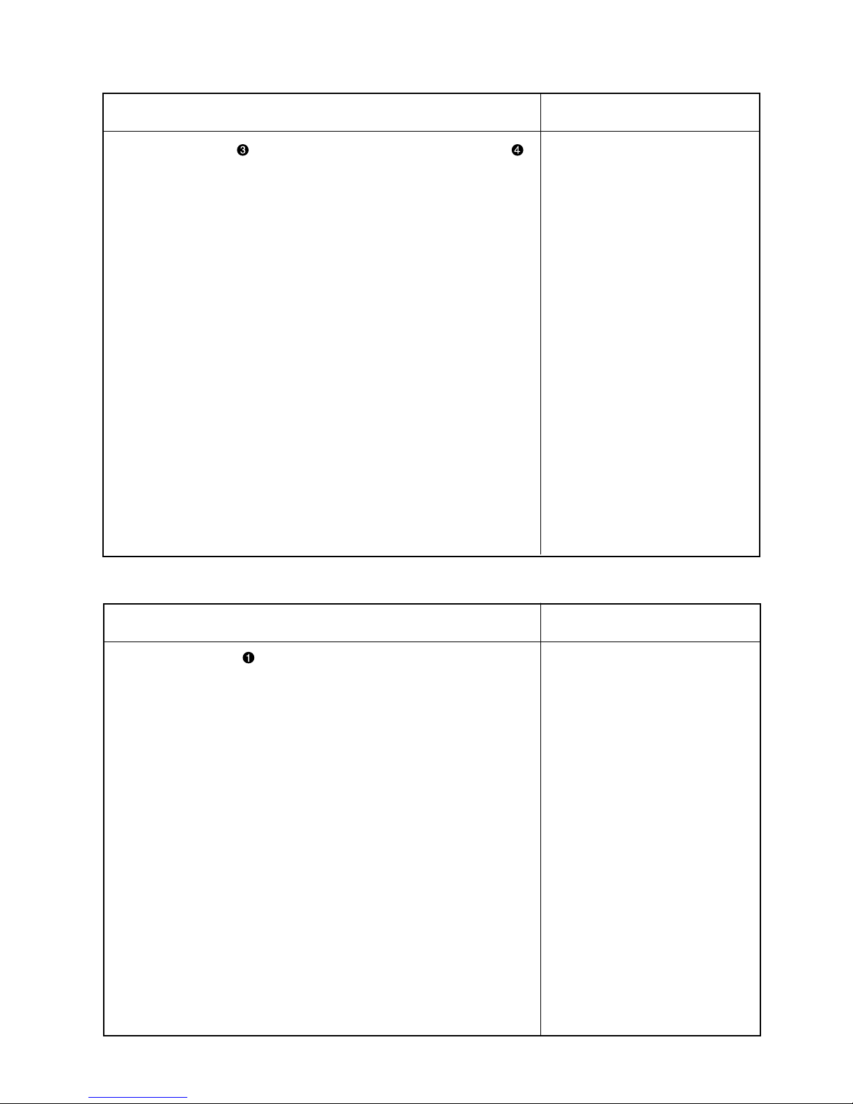
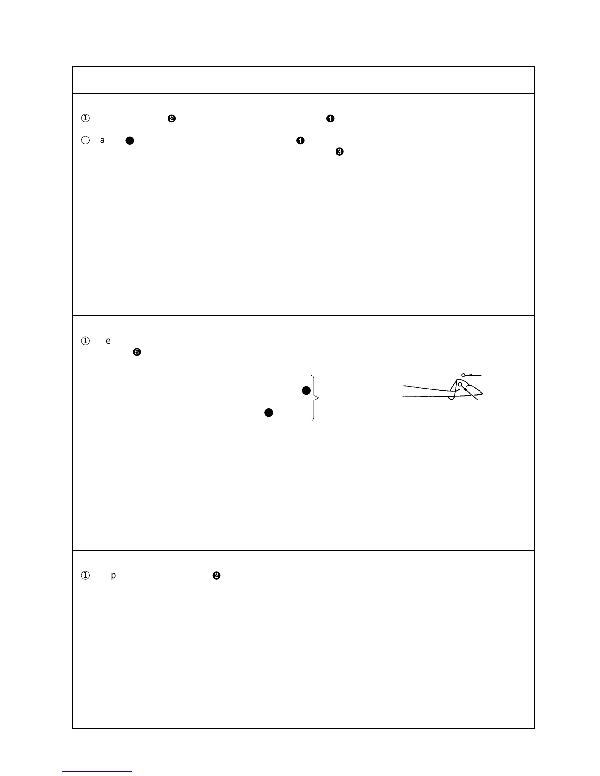
1) Loosen setscrew and adjust, by slightly turning needle clamp ,
the clearance provided between the right-hand side needle and the
lower looper (for 2-needle overlock machine) and the clearance
provided between the needle hole in the throat plate and the needle
(for safety stitch machine).
o If the clearance provided
between the needle and the
looper is excessive, the needle
thread will be likely to skip at the
time of tucking.
o If the clearance provided
between the needle and the
looper is insufficient, the needle
will break or the looper blade
point will be damaged causing
thread breakage.
1) Loosen setscrew of the lower looper holder from the rear of the
frame.
Since it is difficult to accurately measure the center-to-center distance,
perform adjustment to provide a 3.5 mm distance between the end
surface of the arm and the neck of the ball as illustrated.
o Increasing the center-to-center
distance will give a smaller stroke
of the double chain looper or
lower looper, and decreasing the
distance will give larger stroke.
Adjustment Procedure Results of Improper Adjustment
Adjustment Procedure Results of Improper Adjustment
Page 12
– 8 –
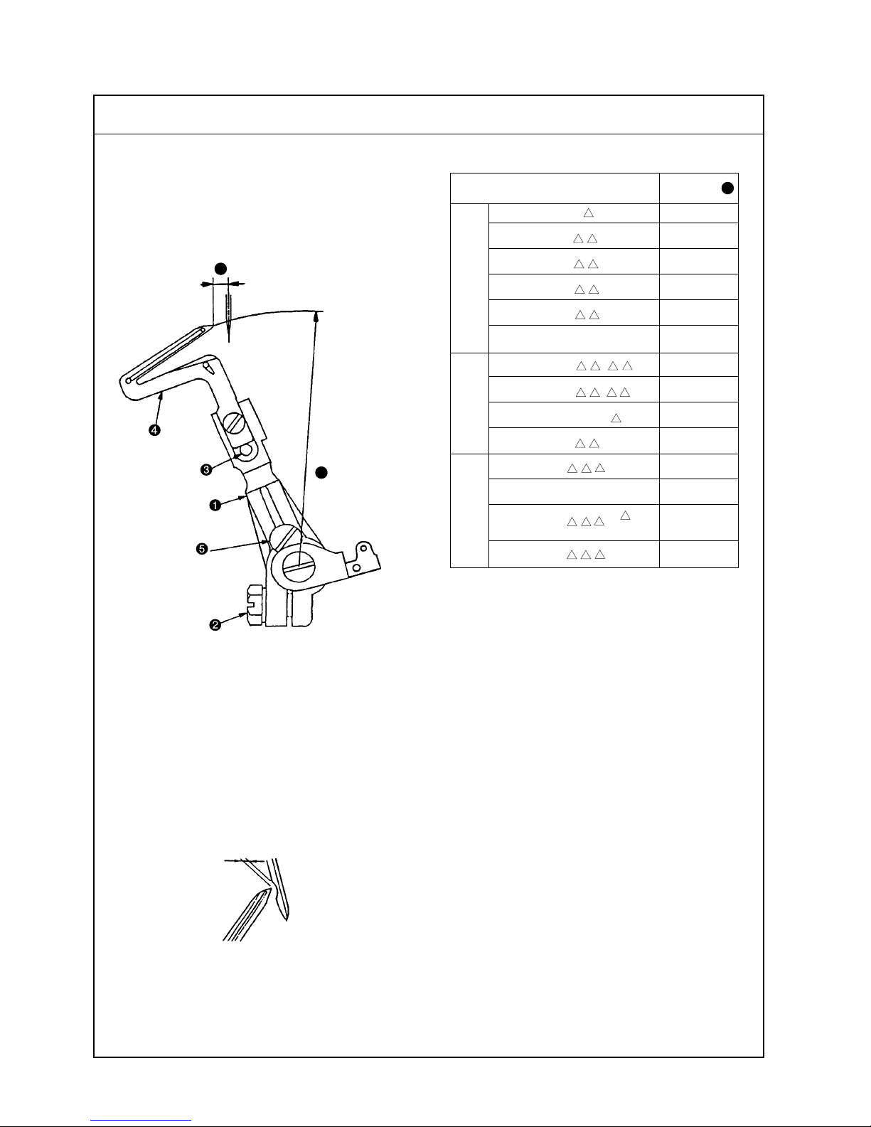
1) Returning amount of the lower looper
The distance between the blade point of the lower
looper and the center of the needle should be as
follows when the lower looper is at the extreme
left of its stroke.
(5) Adjusting the lower looper
Model
MO-6704D-0A -150 4.0
MO-6705D-0 -210 4.0
MO-6704D-0 -300 3.8
MO-6704D-0 -307 3.8
MO-6704D-0 -40H 3.8
MO-6704D-0F6-50H 3.8
MO-6714D-B - 7 3.8
MO-6714D-B - H 4.0
MO-6712D-DF6-50 2.2
MO-6714D-B -30P 3.8
MO-6716D- -300 3.8
MO-6716D-FF6-307 3.8
MO-6716D- - 3.8
MO-6716D- -30P 3.8
(Unit : mm)
0.01 to 0.1 mm
Dimension
J
J
K
(66.9±0.2mm)
Standard Adjustment
1-needle overlock
machine
2-needle overlock
machine
Safety stitch
machine
2) Clearance between the lower looper and the needle
The clearance should be 0.01 to 0.1 mm.
4 H
50H
Page 13

– 9 –
o Excessive return of the lower
looper tends to cause stitch
skipping when filament thread is
used.
o Insufficient return of the lower
lopper tends to cause needle
thread stitch skipping when spun
thread is used.
o Excessive clearance will often
cause needle thread stitch
skipping.
o Insufficient clearance will cause
needle breakage due to the contact of the looper with the needle,
or produce scratches on the
blade point of the looper, leading to needle thread breakage or
other troubles.
1) Returning amount of the lower looper
1
Loosen setscrew of lower looper support arm and adjust lower
looper to make adjustment of the returning amount.
(Referential information)
1. Radius K of lower looper will be 66.9 mm when the lower
looper is inserted into lower looper support arm until it contacts with stopper pin and then is fixed.
2. The rocking angle of the lower looper will be 26°.
2) Clearance between the lower looper and the needle
1
Loosen setscrew of lower looper support arm to the extent that
it is temporarily tightened. Then finely adjust the longitudinal position
of the looper using fine adjustment screw .
2
Turn fine adjustment screw clockwise to move lower looper away
from the needle.
Turn the screw counterclockwise to move lower looper closer to it.
Adjustment Procedure Results of Improper Adjustment
Page 14
– 10 –
MO- 6704D - 0E to 0F - 4 H
MO- 6714D - BB6 to BE6- 30P
BD4 to BE4
BD6 to BE6
MO- 6716D - - 30P
D
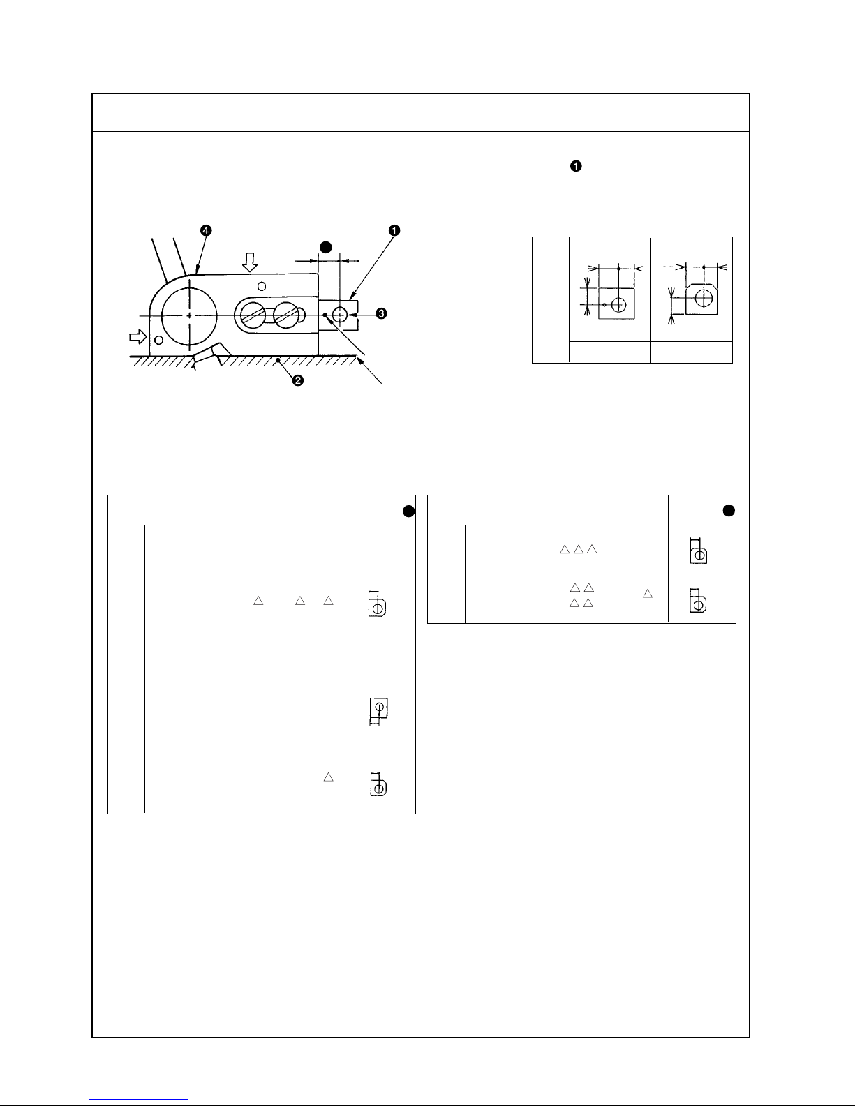
F
(6) Position of the upper looper guide
Vertical position : To be in close contact with the frame guide surface.
Laternal position : To be pressed against the upper looper guide support gauge .
13131909 13132006
Model
Dimension
G
MO- 6714D - - 4 H
(Unit : mm)
(Unit : mm)
Model
Dimension
G
(Unit : mm)
7 5.5
6
6.3 4.7
5.8
5.8
6.3
5.8
5.8
6
G
Marker dot
Frame guide surface
MO- 6716D - - 4 H
Standard Adjustment
Upper looper guide
support gauge
1-needle overlock
machine
2-needle overlock
machine
Safety stitch
machine
Page 15
– 11 –
1) Fit upper looper guide support gauge over gauge fixing pin which
has been driven in frame and secure the gauge with an O ring.
Then position the gauge taking the marker dot engraved on it or the
chamfering direction as reference.
2) When installing upper looper guide support , press it against the
gauge while keeping the upper looper guide support into close contact with the frame guide surface, then tighten the screws.
(Caution) Refer to “4- (4) -1) – 7 Various sealantsî for the various
sealants.
o If the upper looper guide has
improperly positioned vertically,
it will cause oil leakage or
disturbed path of the upper
looper with resultant stitch
skipping.
o If the upper looper guide has
been inaccurately positioned laterally , it will cause stitch skipping,
or contact with the looper.
Adjustment Procedure Results of Improper Adjustment
Page 16

– 12 –
(7) Positioning the upper looper holder
Model
MO- 6704D - 0E to 0F - 4 H 48.2
MO- 6714D - BB6 to BE6 - 30P 47.3
BD4to BE4
BD6 to BE6
MO- 6716D - - 30P 46.2
D
F
MO- 6714D - - 4 H 48.4
Dimension
F
The distance between the bottom surface of the frame and the upper end of the upper looper holder pin
should be as shown below when the upper looper holder is at the highest point of its stroke.
(Unit : mm)
Bottom surface of frame
53mm
F
0.2mm
0.2mm
MO- 6716D - - 4 H 48.2
Standard Adjustment
1-needle overlock
machine
2-needle overlock
machine
Safety stitch
machine
Page 17
– 13 –
1) Loosen the setscrew of upper looper ball arm and setscrew of
the upper looper holder.
2) Adjust the clearances between upper looper bracket and upper
looper holder to approximately 0.2 mm respectively, and tighten
setscrew of the upper looper holder.
(Make sure that the upper looper holder smoothly moves together
with upper looper shaft .)
3) Then determine dimension F from the bottom surface of the frame to
the top surface of upper looper holder pin before tightening the
setscrew of upper looper ball arm .
(Caution) Replace upper looper holder according to the needle
gauge size.
o Inaccurately positioned upper
looper holder will cause
excessive projection of the upper
looper, resulting in stitch
skipping, or contact.
(Caution) To adjust the upper
looper ball arm, take
dimension
FF
FF
F
as stan-
dard.
Remember that the
projecting amount
and the height of the
upper looper should
eventually be properly adjusted. So,
confirm the dimensions related to the
upper looper.
Adjustment Procedure Results of Improper Adjustment
Page 18
– 14 –
(8) Positioning the upper looper
1) Height of the upper looper
The distance between the throat plate surface and the blade point of the looper should be as follows when
the upper looper is at the extreme left of its travel.
2) Longitudinal position of the upper looper
1
The clearance between upper looper
and lower looper should be 0.05 to 0.2 mm when they cross
with each other.
2
The clearance between upper looper and needle should be 0.01 to 0.2 mm.
D
0.05 to 0.2 mm
0.01 to 0.2 mm
Model
DimensionDDimension
E
MO-6704D-0A -150 11.0 4.0
MO-6705D-0 -210 11.0 4.0
MO-6704D-0 -300 11.0 4.0
MO-6704D-0 -307 10.3 4.4
MO-6704D-0 -40H 11.3 4.4
MO-6704D-0F6-50H 11.3 4.4
MO-6714D-B - 7 10.3 4.4
MO-6714D-B - H 10.5 4.8
MO-6712D-DF6-50 11.0 3.6
MO-6714D-B -30P 10.3 4.4
MO-6716D- -300 11.0 4.0
MO-6716D-FF6-307 10.3 4.4
MO-6716D- - 11.3 4.4
MO-6716D- -30P 11.0 4.0
(Unit : mm)
EE
EE
E
E
D
E
D
Standard Adjustment
Throat plate
1-needle overlock
machine
2-needle overlock
machine
Safety stitch
machine
4 H
50H
Page 19
– 15 –
1) Height of the upper looper
1
Set a hexagon wrench key onto setscrew at the end of upper looper
bracket to adjust height D.
2
When adjusting the height, pay attention also to the clearance produced between the upper looper and lower looper at the time of
their crossing.
2) Longitudinal position of the upper looper
1
Loosen setscrew at the top end of upper looper bracket to move
upper looper back or forth for positioning the clearance of 0.05 to
0.2 mm between upper looper and lower looper at the time of
their crossing or the clearance of 0.01 to 0.2 mm between upper looper
and needle .
o If the upper looper has been
positioned too high, an excessive
clearance will be produced
between the upper looper and
the needle. As the result, the
upper looper thread will fail to
catch the needle thread, and
stitch skipping occurs.
o On the contrary, if the upper
looper has been positioned too
low, the needle point will hit the
looper, causing needle breakage. Also the looper will touch
other component when the
presser foot goes up.
o Excessive clearance will cause
stitch skipping.
o Insufficient clearance will cause
the upper looper to come in contact with the lower looper.
Adjustment Procedure Results of Improper Adjustment
Page 20
– 16 –
1.5 to 1.7 mm
(63.4 mm)
M
1) Returning amount of the double chain looper
The distance between the needle center and the blade point of the double chain looper should be 1.5 to 1.7
mm when the looper is at the extreme left of its travel.
2) Longitudinal motion (Avoid motion)
The standard minor axis of the elliptical motion should be :
3.0 mm.
Note : The avoid motion should be adjusted in accordance with Needle No.
3) Clearance between the double chain looper and the needle
The clearance should be 0.05 to 0.1 mm.
(9) Adjusting the double chain looper (Applicable only to MO-6716D series)
3.0 to 3.6 mm
0.05 to 0.1 mm
Standard Adjustment
Marker
Hole
Marker
A
B
Page 21
– 17 –
1) Returning amount of the double chain looper
1
Loosen setscrew of double chain lopper driving arm to make
this adjustment.
2
Radius Mof the double chain looper driving arm will be 63.4 mm
when it is lowered until it comes in contact with stopper pin .
2) Longitudinal motion (Avoid motion)
1
Open the cover of the adjusting hole on the rear of the frame, loosen
setscrew , and put a Ø2 rod in the hole. Now, make the adjustment
by turning the rod back and forth.
Marker : This side
..... Minimum (for standard to thin needle)
A
Marker : Far side
..... Maximum (for thick needles)
B
3) Clearance between the double chain looper and the needle
1
Temporarily tighten setscrew in the double chain looper, and finely
adjust the longitudinal position of the double chain looper. Adjust the
clearance to 0.05 to 0.1 mm.
o Excessive return of the double
chain looper will cause frequent
stitch skipping when filament
thread is used.
o Insufficient return of the double
chain looper will cause frequent
thread stitch skipping when a
spun thread is used.
o If the avoid motion is too large,
triangle stitch skipping will often
occur.
o Insufficient avoid motion will
cause the needle point to hit the
looper, producing scratches on
the needle point or looper.
o Excessive clearance will cause
frequent needle thread stitch
skipping.
o Insufficient clearance will cause
to looper to hit the needle, leading to needle breakage or
scratches on the looper blade
point with consequent thread
breakage.
As observed
from this side
Adjustment Procedure Results of Improper Adjustment
Bad needle
entry
Good needle
entry
Page 22

– 18 –
(10) Adjusting the height and clearance of the needle guard
1) For 1-needle or 2-needle overlock machine
The overlock machine has two needle guards, A and B.
The needle guard B should be located 1 mm below the throat plate bottom surface.
2) For safely stitch machine
The safely stitch machine has four needle guards, A, B, C and D. The needle guards A and B are
positioned in the same manner as those for the overlock machine.
The needle guard C should be positioned 5 mm below the throat plate bottom surface.
Needle guard
A
Needle guard
B
Throat plate
1 mm
0.1 mm
B
Throat plate
5 mm
B
0.1 m
m
D
C
(Traveling needle guard)
A
Standard Adjustment
Light
touch
the
needle
guard
Lightly touches
Page 23

– 19 –
1) For 1-needle or 2-needle overlock machine
1
Adjust needle guard A with setscrews in the needle guard so that
it lightly comes in contact with the needle when the blade point of the
lower looper reaches the needle center.
2
To adjust the clearance provided between needle guard B and the
needle when the needle bar is at the lowest point of its stroke, loosen
setscrews in the needle guard support and turn needle guard B to
adjust the clearance to 0.1 mm.
3
Adjust the height of needle guard B to 1 mm from the throat plate
bottom surface with setscrew in the needle guard.
2) For safety stitch machine
1
Loosen setscrews in the needle guard, and adjust the clearance
provided between needle guard C and the needle so that it lightly
comes in contact with the needle.
2
Adjust the installing height of needle guard C to 5 mm with setscrew
in the needle guard.
3
Adjust the clearance provided between needle guard D and the needle
to 0.1 mm with setscrews .
(Caution) Check again the clearance provided between needle guard
B
and the needle after adjusting the height of needle
guard C.
o Excessively close contact
between the needle guard
A
and the needles will lead to
needle bend or stitch skipping.
oA clearance left between the needle
guard A and the needles will cause
the looper blade point to come in
contact with the needles, leading to
needle or blade point breakage, or
other troubles.
o If the needle guard B is too high,
thread loops will be damaged
with resultant stitch skipping.
Also, double chain loops will be
affected, causing double chain
stitch skipping.
o If the needle guard B is too low,
the needle cooling felt will be lowered, resulting in deteriorated effect
of the cooling and needle guard.
oExcessive clearance between
the needle guard Band the
needle will cause stitch skipping
due to needle shake. On the contrary, insufficient clearance will
cause the needle guards to catch
the needles between them, leading to wear on the needle guards
and scratches on the needles.
o If the needle guard C is too high,
the needle thread loops will be
damaged, and stitch skipping
occurs. If it is too low, the needle
points will be crushed.
o If the clearance between the
needle guard C and the needles
is too large, the double chain
looper blade point will come in
contact with the needles, causing
the breakage of the needles,
causing the breakage of the
needles or looper blade point.
No clearance left between them
will cause them to come in excessively close contact with each other,
and bend of needle, wear on the
needle guard and scratches on the
needles will occur.
o Excessive clearance left be-
tween the needle guard D and
the needles will cause stitch skipping due to needle shake, and
insufficient clearance will cause
the needle guards to catch the
needles between them, leading
to wear on the needle guards
and scratches on the needles.
Adjustment Procedure Results of Improper Adjustment
Page 24

– 20 –
(11) Adjusting the height of the feed dog
The height of main feed dog from the top surface of the throat plate should be as follows when it is at its
highest position.
[Standard]
Auxiliary feed dog is 0.5 mm lower than main feed dog .
B = 0.5 mm
[30P]
Auxiliary feed dog is as high as main feed dog .
B = 0 mm
Model Dimension A
MO-6700D series (30P excluded) 1.0
MO-67 D- -30P 0.8
(12) Adjusting the tilt of the feed dog
Tilt of the feed dogs when
the feed dogs have come
up most.
Model Dimension A Dimension B
MO-6700D series (30P excluded) 1.0 (1.2)
MO-67 D- -30P 0.8 (0.9)
(Unit : mm)
When the feed dog juts
out the top surface of
the throat plate
Top surface of
the throat plate
Feed dog is leveled.
B
Needle
entry
A
B
Front up
(Unit : mm)
In case of 30P type
15
°
Standard Adjustment
Standard Adjustment
A
Needle
entry
Page 25

– 21 –
o If the feed dogs are too high, the
needles will be deflected and
broken when sewing heavyweight
materials. The feed dogs will tend
to suffer scratches when sewing
light-weight materials. Puckering
will frequently occur.
o If the feed dogs are too low, in-
sufficient feed power will result.
o If the auxiliary feed dog is too
high, chain-off thread will be often jammed.
o If the main feed dog and differ-
ential feed dog are set at different heights, proper differential
feeding action will be hindered.
1) Adjust the height of main feed dog to dimension A with setscrew
.
2) Adjust the height of differential feed dog with setscrew so that
there is no difference in level between main feed dog and differential feed dog .
3) Adjust the height of auxiliary feed dog with setscrew so that it is
0.5 mm lower than main feed dog .
o When tilted with the front up
Good material catching will be
obtained.
oWhen tilted with the front down
Uneven feed and puckering will
be effectively prevented.
1) Use the tilt of the feed dog when it is in its highest position as a
reference and adjust so that the feed dog is flush with the throat plate
when the feed dog juts out the throat plate.
2) Feed bar shaft consists of an eccentric shaft. Loosen setscrew
to perform adjustment.
When the marker line is set at middle
.....The feed dog will be flat.
When the marker line is set at bottom
.....The feed dog will be tilted with its front up (in the arrowed direc-
tion).
When the marker line is set at top
.....The feed dog will be tilted with its front down.
(Caution) The marker line should be used just as the reference since
it slightly differs with that of each machine due to the
disparity of the components.
Confirm the accurate tilt of the feed dog by observing
the feed dog itself.
Adjustment Procedure Results of Improper Adjustment
Adjustment Procedure Results of Improper Adjustment
Page 26

– 22 –
(13) Adjusting the differential feed ratio
(Standard)
Gathering: 1: 2
Stretching: 1: 0.7
(Max, stretching)
Gathering: 1:1.6
Stretching: 1:0.6
(Max, gathering)
Gathering: 1: 4
Stretching: 1: 1.3
Pin at its highest
position
Washer
Pin at its lowest
position
(14) Longitudinal position of the feed dog
When the feed pitch is maximized and the differential feed ratio is also maximized, the clearances of the front
and rear ends of the feed dog, and the throat plate should be spaced approximately 0.5 mm respectively.
0.5mm
0.5mm
Standard Adjustment
Standard Adjustment
Center of
nut Lower
marker line
Page 27

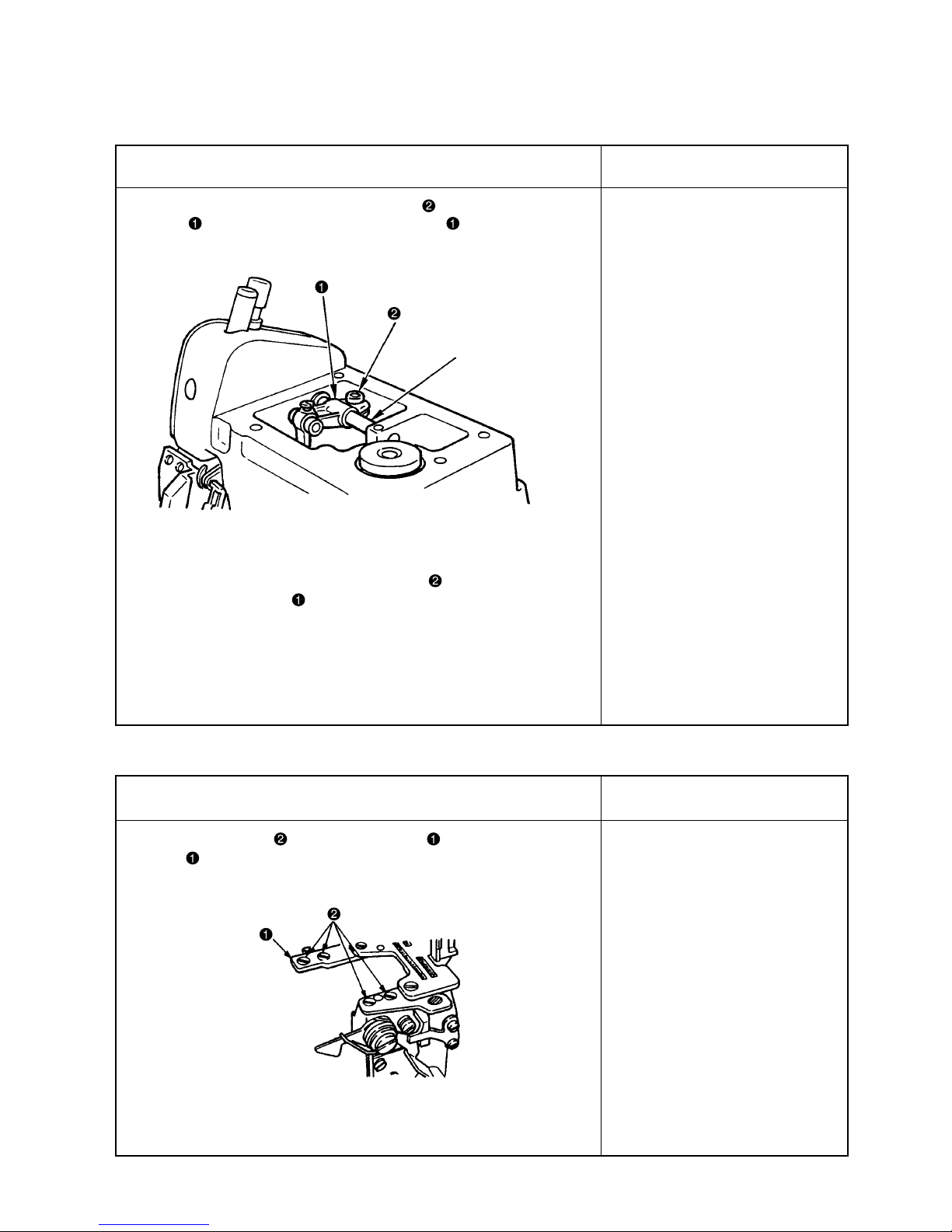
– 23 –
1) Remove cover on the rear of the frame and loosen main feed pin
and nut .
2) Move main feed pin up or down to adjust the differential feed ratio.
3) Adjust so that the lower engraved marker line on main feed rocker
aligns with the center of nut . (Standard)
4) When adjusting the maximum stretching, adjust main feed pin to
the highest position.
5) When adjusting the maximum gathering, adjust main feed pin to
the lowest position.
6) After performing adjustment, tighten the main feed pin and nut ,
and install cover .
o If the clearance provided
between the throat plate and the
feed dog is too small, they will
come in contact with each other
when the sewing machine runs
at high speed
1) Remove the cover on the rear of the frame, loosen main feed bracket
clamping screw and differential feed bracket clamping screw ,
and adjust the clearances provided between the front and rear ends
of the feed dogs and the slots in the throat plates to approximately
0.5 mm. Then tighten main feed bracket clamping screw and
differential feed bracket clamping screw .
Adjustment Procedure Results of Improper Adjustment
Adjustment Procedure Results of Improper Adjustment
Page 28

– 24 –
(15) Adjusting the presser foot
1) Adjusting the tilt of the presser foot
The presser foot should be positioned so that the feed dogs go down under the specified presser foot
pressure, and the presser foot sole comes in contact evenly with the throat plate surface.
2) Adjusting the micro-lifting mechanism of the presser foot
Throat plate
Standard Adjustment
Page 29

– 25 –
o Uneven contact will result in bad
straight material feed and weak
feed force. Puckering is apt to
occur as well.
1) Adjusting the tilt of the presser foot
1
Turn the handwheel and place the feed dog in the position where the
feed dog does not jut out the top surface of the throat plate.
2
Loosen setscrew and adjust so that the presser foot sole comes in
contact evenly with the throat plate top surface. Then tighten setscrew .
(Reference) Accurate adjustment can be made by using two pieces
of thin paper to check for even drawing-out tension.
In addition, even contact of the presser foot with the
throat plate top surface is achieved rather easily by
tightening the screw while pushing the right side of
the presser foot.
2) Adjusting the micro-lifting mechanism of the presser foot
1
When moving presser lifting lever just a little, perform it with fine
adjustment screw .
Adjustment Procedure Results of Improper Adjustment
Page 30

– 26 –
1) Lower knife
2) Upper knife
3) Overedging width
Overedging width can be adjusted from 1.6 to 6.4 mm.
(16) Positioning the upper knife arm shaft
(17) Positioning the upper and lower knives, and available overedge widths
The upper knife shaft should be positioned 34 mm above the top surface of the throat plate when it is at its
highest position.
34mm
Lower knife
Throat plate
Standard Adjustment
Standard Adjustment
Upper knife
0.5 to 1 mm
Page 31

– 27 –
oImproperly positioned upper
knife arm shaft will come in
contact with the frame.
If it is moved with the position of
the upper knife unchanged,
proper engagement of the knives
will be disturbed, prohibiting
sharp cutting of the knives.
1) Remove the upper cover, loosen setscrew in upper knife driving
arm , and turn upper knife shaft to adjust the position from the
top surface of the throat plate to 34 mm.
(Caution) Be sure to fully tighten the setscrew since upper knife
shaft is subjected to high load.
o The lower knife, if positioned too
high, will catch materials or
cause no contact of the presser
foot with the throat plate top surface.
o If the lower knife is positioned too
low, the cutting width will be
changed or materials will be
caught by the lower knife.
o The upper knife, if positioned too
high, will fail to cut materials.
o Failure of cutting or abnormal
wear on the knives will result
unless the lower knife is laterally
positioned and fixed at a position
where it has settled by itself under the upper knife spring.
1) Lower knife
1
Adjust the vertical position of the lower knife by screw so that the
blade top aligns with the top surface of the throat plate.
2
Tighten screw after bringing the upper knife to its lowest position
of its stroke.
2) Upper knife
1
Adjust the position of the upper knife by screw so that the engagement with the lower knife is 0.5 to 1 mm when the upper knife is in the
lowest position of its stroke.
(Caution) Adjust the lateral position of the lower knife by screw .
Adjust the lateral position of the upper knife by screw .
After performing adjustment, be sure to fix the knife. Otherwise, the durability of the knife will be affected.
3) Overedging width
1
Adjust the overedging width in the following way :
Laterally position the upper knife before loosening screw .
Tighten screw when the upper knife has settled by itself under the
pressure applied by the spring. Repeat this adjustment procedure to
obtain desired overedging width.
Adjustment Procedure Results of Improper Adjustment
Adjustment Procedure Results of Improper Adjustment
Page 32

– 28 –
(18) Resharpening of the knife
(19) Position of the thread cam (Applicable only to MO-6716D series)
1) Adjustment of the thread cam
2) Adjusting looper thread cam thread guides A and B and the looper thread cam nail
10°
55°
Standard Adjustment
Standard Adjustment
Level
Level
Page 33

– 29 –
1) Adjusting the thread cam
1
Adjust the position of the thread cam by its setscrew with the
needles at their upper dead point so that the straight section of the
thread cam is leveled.
2
Laterally position the thread cam so that the looper thread cam nail is
located at the center of the thread cam groove.
[How to check for proper positioning]
Check that the thread cam releases the looper thread when the needle
tip begins to come out of the bottom surface of the throat plate by 0 to 1
mm.
2) Adjusting the looper thread cam thread guides A and B and the
looper thread cam nail
1
Install looper thread cam thread guides A and B at the center of
the slots with setscrews A and B .
2
Install looper thread cam nail with setscrew so that the straight
section of the forked portion is leveled.
o If the 10∞ angle of the lower knife
is exceeded, the durability of the
knife will be deteriorated, often
resulting in blade chipping.
o If the angle is smaller than 10°,
the knife will be dull.
o If the 55° angle is not observed,
the knife may catch materials.
1) When the knives have become dull, fully resharpen lower knife
until the contact mark of it disappears.
2) When the upper knife has become dull, replace it with a new one.
(This is because the upper knife is a serrated carbide knife.)
o If the timing of the thread cam is
too early, the needle point will fail
to enter a thread triangle,
resulting in looper thread stitch
skipping.
o If the timing of the thread cam is
too late, puckering and loose
looper thread stitches will results.
o If the chain looper thread guide
is moved away from you, the
take-up amount of the lower
looper thread will decrease. In
this case, puckering may result
there by impairing the feeling of
the finished product.
Throat plate
0 to 1 mm
Thread
Adjustment Procedure Results of Improper Adjustment
Adjustment Procedure Results of Improper Adjustment
Page 34

– 30 –
(19) Position of the thread cam (Applicable only to MO-6716D series)
3) Adjusting looper thread auxiliary thread take-up lever (Exclusive for 30P)
When lopper thread auxiliary thread take-up lever is in its lower dead point, the thred hole should align
with the hole in lopper thread auxiliary thread take-up lever guide .
The holes should align
with each other at the
lower dead point.
Standard Adjustment
Page 35

– 31 –
1) Open the cloth base cover and loosen setscrew .
2) When looper thread auxiliary thread take-up lever is in its lower
dead point (when the feed dog goes back to the end), tighten setscrew so that the thread hole in looper thread auxiliary thread
take-up lever aligns with the thread hole in looper thread auxiliary
thread take-up lever guide .
(Caution) 1. When the feed pitch is changed, perform re-adjustment.
2. Confirm that looper thread auxiliary thread take-up le-
ver does not come in contact with the cloth base
cover.
Adjustment Procedure Results of Improper Adjustment
Page 36

– 32 –
(20) Adjusting the throat plate support
(21) Adjusting the feed mechanism cover presser
Standard Adjustment
Standard Adjustment
Uniform contact
Page 37

– 33 –
oIf the throat plate support comes
in single sided contact with the
throat plate or does not come in
contact with it, the throat plate will
vibrate severely.
1) Loosen setscrews and adjust so that throat plate support should
not come in single-sided contact but come in uniform contact with
throat plate using setscrews .
o If the feed mechanism cover is
not fully pressed and the cover
rises, oil leakage will be caused.
1) Loosen setscrew and press feed mechanism cover presser in
the direction of arrow.
2) Press feed mechanism cover and tighten setscrew so that the
feed mechanism cover should not rise.
(Caution) Check that feed mechanism cover is pressed so that it
should not rise.
Adjustment Procedure Results of Improper Adjustment
Adjustment Procedure Results of Improper Adjustment
Page 38

– 34 –
(22) Adjusting the looper cover
o The looper cover should smoothly close without coming in contact with upper knife when slowly closing
looper cover with upper knife in its lowest position of its troke.
(23) Adjusting the cloth chip cover
o When cloth chip cover is pressed away from you, it should not rattle.
In addition, the cloth chip cover should not come in contact with upper knife and lower looper .
(There are 2 pcs. inside.)
Frame
Cloth chip
cover
Standard Adjustment
Standard Adjustment
Page 39

– 35 –
1) Close looper cover , loosen setscrew , and move looper cover
guide plate back and forth until the looper cover is brought to a
position where the cover smoothly closes.
2) Move looper cover guide plate until it slightly comes in contact
with looper cover receiving bracket . Now, fix the guide plate by
tightening setscrew .
1) Loosen setscrew and temporarily tighten the setscrew with cloth
chip cover stopper raised.
2) Loosen setscrews in the cloth chip cover , and adjust the longitudinal position of cloth chip cover .
3) Loosen setscrew in the cloth chip cover stopper again, and press
cloth chip cover stopper downward until the stopper slightly comes
in contact with looper cover . Now, tighten setscrew .
4) Finally , confirm that cloth chip cover comes in contact with neither
upper knife nor lower looper .
Adjustment Procedure Results of Improper Adjustment
Adjustment Procedure Results of Improper Adjustment
Page 40

– 36 –
(Caution) The needle thread take-up shall be positioned at the lower dead point.
B
A
C
D
Needle thread guide
Needle thread take-up guide
of double-chainstitch machine
P
Needle thread takeup lever of doublechainstitch machine
(24) Position of the thread guides and the looper thread take-ups
MO-6704D MO-6714D MO-6716D
Needle thread
take-up
B
Needle thread
guide
A
B
A
Needle thread take-up lever of
2-needle machine
Needle thread guide of
2-needle machine
The thread hole in the needle thread
guide and the hooked portion of the
needle thread take-up are in the position where 2/3 of the hole in the needle
thread guide can be observed.
The thread hole in the needle thread guide and
the hooked portion of the needle thread take-up
are in the position where 2/3 of the hole in the
needle thread guide can be observed.
The thread hole in the double-chainstitch needle
thread guide and the hooked portion of the needle
thread take-up are in the position where the entire
hole in the needle thread guide can be observed.
The thread hole in the needle thread
guide and the hooked portion of the
needle thread take-up are in the position where 2/3 of the hole in the needle
thread guide can be observed.
Upper looper thread guide (upper)
Upper looper thread guide (middle)
Looper thread take-up (left)
Looper thread t
ake-up (right)
Lower looper thread take-up
E
N
M
J
H
F
K
G
Upper looper thread guide (right)
Lower looper thread guide
I
L
MO-6 04D MO-6 14D MO-6 16D MO-6 16D MO-6 05D MO-6 04D
(Standard) (Standard) (Standard) (50H) (Blind-hemming) (Soft chain)
General thread Wooly thread General thread Wooly thread General thread Wooly thread General thread General thread Wooly thread General thread
15.8 ←←←←← ← ← ← 13.5
3.4 ←←←1.8 ← 2.6 3.4 ← 2.1
————21.5 ← 2.3 — — —
————30.5 ← 24.5 — — —
22 ←←←←← ← ← ← ←
65 ←←←←← ← ← ← ←
17.5 ←←←←← ← ← ← ←
43.5 ←←←←← ← 40.5 ← 43.5
26.5 ←←←←← ← 24 ← 26.5
38 41 38 ← 34 36 34 38 42 43.5
15 ← 12 15 12 15 12 12 ← 14
6.5 ← 10 ← 6.5 ←← 24 34 ←
29 ←←←27.5 ←← 29 ← 26.5
27 21 23 ← 20 ← 19 24 ← 19
11 ←←←←← ← 12 ← 9.5
————16← 12.8 — — —
Symbol
A
B
C
D
E
F
G
H
I
J
K
L
M
N
O
P
(Unit : mm)
Standard Adjustment
Page 41

– 37 –
1) Perform the adjustment by the setscrews. Position of the needle thread
guide and needle thread take up lever is a very important decisive
factor when making soft chains since the needle thread take-up
amount is increased in this case. So, carefully position these parts.
2) Set distance I a little smaller when using
synthetic thread or the like which tends to form
stitches swelling out of the cloth edge.
A smaller I is effective for preventing stitch skipping.
3) Distance J is related to the vertical knotting point
of the upper and lower looper threads.
Set this distance larger for wooly thread, and set it smaller for thin
thread which is likely to cause stitch skipping.
4) It is desirable to set distance K larger for stretchy threads such as
wooly thread.
5) Set distance L a little larger when making blind hemming soft chain
stitches.
6) Set distance N a little smaller for blind hemming or making soft chain
stitches.
7) Set distance O larger if stitch skipping occurs due to looper thread
slack.
Set it smaller for better appearance and touch of produced stitches
when wooly thread is used.
o Distance
a
When set smaller, better tightness of needle thread stitches
will be obtained.
When set larger, loose needle
thread stitches will result.
o Distance E, F and H exert least
influence on stitch formation,
however, improper setting of
these distances will cause contact between the moving parts.
o Distance J
When set larger, the amount of
the upper looper thread will be
increased.
When set smaller, the amount of
the upper looper thread will be
decreased.
oDistance K
When set larger, the amount of
the upper looper thread will be
increased.
When set smaller, the amount of
the upper looper thread will be
decreased.
o Distance L
When set larger, the amount of
the upper looper thread will be
increased.
When set smaller, the amount of
the upper looper thread will be
decreased.
o Distance N
When set larger, the amount of
the upper looper thread will be
increased.
When set smaller, the amount of
the upper looper thread will be
decreased.
o Distance I
When set larger, the amount of
the upper and lower looper
threads will be increased.
When set smaller, the amount of
the upper and lower looper
threads will be decreased.
o Distance O
When set larger, the amount of
the upper and lower looper
threads will be decreased.
When set smaller, the amount of
the upper and lower looper
threads will be increased.
Swell out
Adjustment Procedure Results of Improper Adjustment
Needle thread take-up amount
a
Large
Small
Lower looper
Thread slack
Upper looper
Upper looper
Needle
Thread slack
Page 42

– 38 –
1) Replacing the parts with those exclusively designed for making soft chains
Needle thread presser plate C .......12112504
Driving cam .................................... 12112603
Needle thread presser spring B ..... 12112702
Throat plate ....................................(only for 1-needle
overlock machine)
0D4-300 ......................................... R4200J6DD0A
2) Adjustment value
1
Needle thread guide and needle thread take-up lever
Adjust the needle thread guide to increase the needle thread feeding amount when the needle bar is in
the lowest dead point of its stroke.
(04 1-needle overlock machine) (16 Safely stitch machine)
2
Adjust the rising amount of needle thread presser plate C.
Adjust the rising amount of needle thread presser plate C to 0.6 to 1 mm (max.) by moving driving
cam to the right and left within the slot.
Rising amount : 0.6 to 1 mm (max.)
(25) Adjusting soft chain making mechanism
Max. slot of the needle
thread guide
3.1 to 3.6mm
Max. slot of the needle
thread guide
Needle thread takeup amount when the
needle bar is in its
lowest dead point
2.5 to 3mm
Standard Adjustment
Cam face
Needle thread take-up
amount when the needle
bar is in its lowest dead
point
Rising amount
Cam face
Page 43

– 39 –
3) Important points in adjustment
1
Increase the thread take-up amount of the needle thread take-up lever.
Refer to the adjustment values related to the needle thread guide and needle thread take-up lever.
2
Reduce the feed of the looper threads. (Mainly lower looper thread)
Set J, K, L and M for the soft chain distances.
Fine adjustment of J and M is required to produce even stitches.
3
Adjsut the thread tension while checking the appearance and touch of the stitches produced.
1) Minimize the needle thread tension as far as satisfactory tightness of needle thread stitches is obtained.
2) Increase the upper looper thread tension as much as possible.
4
If the chain-off thread does not stretch satisfactorily, and if it is not satisfied, proceed with the following.
1) Increase the upper looper thread tension.
2) Further increase distances J and K.
3) Further increase the upper looper thread tension.
4) Increase the lower looper thread tension to a maximum as far as good tightness of needle thread
stitches is maintained.
5) Increase the thread take-up amount. If the needle thread is poorly tensed, increase the needle thread
tension.
5
Fine adjustment for producing stitches with better appearance and touch
1) If the knotting point varies at high or low sewing speed, slightly reduce L, and increase the lower looper
thread tension.
2) If a knot is made at a high point, increase J and I.
3) If the needle thread is likely to break, decrease the thread take-up amount and lower the needle thread
tension.
6
Pay attention to the following
1) Minimize the needle thread tension as far as satisfactory tightness of needle thread stitches is obtained.
2) The knot of upper and lower looper threads should be made near the upper edge of a material.
3) Minimize the lower looper thread tension as far as even stitches are maintained.
4) For a safety stitch machine, adjust the soft chain making mechanism so that uniform chain-off thread
is produced during double-chain stitching and overlocking.
Soft chain stitches
Standard stitches
The value given in ( ) parentheses is
the adjustment value for the safety
stitch machine. (Unit : mm)
Looper thread
take-up (left)
Looper thread
take-up (right)
Lower looper
thread take-up
Lower looper
thread guide
Upper looper thread
guide (middle)
Upper looper thread guide (upper)
Upper looper thread guide (right)
O
11
M
29 (27.5)
N
27 (20)
G
17.5
K
15 (12)
E
22
I
26.5
F
65
H
43.5
J
38
(34)
L
6.5
Looper thread should not be
loosened and stretch well
The looper thread loosens
When the chain-off
thread is pulled.
When the chain-off
thread is pulled.
Page 44

– 40 –
(2) Upper looper
Use a proper upper looper in accordance with the needle No. When ordering, refer to the Parts List. The
numbers shown in frame in the table below are engraved markers. In addition, the letters in ( )
parentheses are the kinds of the needles.
Parts Nos. with an asterisk * are factory-installed on the standard machine heads at the time of delivery.
Model Nos. engraved on Needle No.
upper looper (kind)
MO-6704D series *1188 81 #9 #11 #14
MO-6716D series
MO-6714D series *1217 60
Part No. Color Natural length Operating length Weight required to compress
(mm) (mm) spring to working length
13137807 Red 19.5mm 11.5mm 4.21±0.49N (430±50g)
13138508 Yellow 17.8mm 9.8mm 3.14±0.34N(320±35g)
13138805 Blue 17.3mm 9.3mm 1.47±0.20N(150±20g)
4. ADDITIONAL INFORMATION AND PRECAUTIONS
2) Springs used for each model.
Needle thread Double-chainstitch Upper looper Lower looper
needle thread thread thread
MO-6704D series Red — Yellow Blue
MO-6714D series Red • Yellow — Blue Yellow
MO-6716D series (30P included) Red Yellow Yellow Blue
MO-6716D- -4 H, -50H Red Red Blue Yellow
Model
Where to use
(1) Thread tension
1) Strength of tension spring
Page 45

– 41 –
(3) Center-to-center distance of the upper looper holder
The center-to-center distance of upper looper holder 1.
Be careful not to allow the
sealant to run to the rear.
Apply the sealant to the
bottom surface.
Apply the sealant to the
bottom surface.
H
(4) Caution in assembly
1) Application of sealant
1
Setscrew of the throat plate base (B) retainer (JUKI seal)
Apply the sealant only to the right setscrew.
2
Bottom surface of the upper looper guide support (Three-bond 1104)
Apply the sealant to the bottom surface of the upper looper guide support , which contacts with the
frame surface.
3
After assembling the front edge of the upper looper guide support (JUKI seal), apply the sealant to
the gap of the contact surface between the frame and the upper looper guide support ( section
in the illustration).
Frame
Apply only to the right setscrew
Model
MO-6704D - MO-6705D - - 0
MO-6704D - 0E4 40H
0F6 50H
MO-6712D -D MO-6714D - MO-6716D - - 0
MO-6716D -DE to FF MO-6743D - - 40H
(Unit : mm)
38
39
39
39
38
39
39
4 H
5 H
-
Center-to-center
distance
H
Page 46

– 42 –
Apply the sealant to the frame.
Apply the sealant to the oil shield rubber support
plate and the top surface of the oil shield case.
Be careful that the sealant should not overflow on
the side of the oil shield rubber.
Feed mechanism
cover (rear face)
Lightly apply the sealant to the rear
face of the feed mechanism cover
and the top surface of the feed bar
presser.
7
Various sealants
Maker’s name Part No.
Three Bond 1104D
Three Bond 1104
Three Bond 1212
* * : It is commonly called “JUKI seal”.
JUKI exclusive part Nos. of the above 3 kinds of the sealants are not set.
4
Portion of the setscrews of the dust-proof rubber case (JUKI seal)
Apply the sealant to the oil shield case setscrew (1 pc.) and the dust-proof rubber case setscrews
(4 pcs.)
5
Oil shield plate assembly (JUKI seal)
Apply the sealant to the inside of the oil shield plate .
6
Portion of the feed mechanism cover (Three-bond 1212)
Apply the sealant to the rear face of the feed mechanism cover, the top surface of the oil shield plate,
the oil shield rubber support plate , the top surface of the oil shield case, and the hatched parts on the
top surface of the feed bar presser.
Apply the sealant to
the hatched parts.
Inside contact surface
Apply the sealant to the
top surface of the oil
shield plate.
Page 47

– 43 –
2) Precautions to be taken with respect to the lubricating components
1
Feed bar components
o Be careful of the orientation of the oil shield rubber and the dust-proof rubber .
* Assembling as shown in the illustration
will result in oil leakage. So, be careful.
2
Portion converted to dry-head type
Forced lubrication room
[Wet portion]
3. Upper looper mechanism portion
[Dry portion]
1. Needle bar mechanism portion
[Dry portion]
2. Feed mechanism portion
[Wet portion]
o Assemble the feed bar presser and the dust-
proof rubber case so that their top faces are
flush with the frame plane on which the feed
mechanism cover is installed.
o Do not loosen the screws in feed bar presser
unless it is necessary. The clearance between
the feed bar presser and the feed bar and the
contact with each other are important.
Do not loosen the screws.
Page 48

– 44 –
3) Applying the exclusive grease
o The exclusive grease (23640204) is applied to the necessary components other than the lubricating com-
ponents. Never use any grease other than the exclusive one.
It is not necessary to additionally apply grease to the components when the sewing machine is used under
the normal condition.
When the machine is used under the specially severe condition, it is effective to periodically (once a year
or every other year) fill up the exclusive grease.
* : Apply the exclusive grease.
1
Needle bar components
*
*
*
*
*
*
*
(Caution) There are grease grooves on the inside
of needle bar upper metal (No. 19) and
needle bar lower metal (No. 18). Fill up
the exclusive grease to the groove portion when drawing out the needle bar.
Page 49

– 45 –
2
Upper looper components
*
*
*
*
*
*
*
*
Page 50

– 46 –
2) Pat No. of frame support plate bolt
1
Semi-sunken type
Support plate bolt (A) 13155007 x 4
Locknut NS6240630SE x 4
Washer WP1002036SE x 4
Spring washer WS1002560KR x 4
2
Fully-sunken type
Support plate bolt (C) 13155106 x 2
Support plate bolt (D) 13155205 x 2
Locknut NS6240630SE x 12
Washer WP1002036SE x 12
Spring washer WS1002560KR x 4
Difference of support plate bolts (A), (C) and (D)
Entire length under the neck and length of threaded part
Entire length Length of threaded part
(mm) (mm)
Support plate bolt (A) 69 39
Support plate bolt (C) 137 107
Support plate bolt (D) 149 119
(5) Kinds of motor pulleys, belts and frame support plate bolts
1) Motor pulleys and belts
50Hz 60Hz
V-belt V-belt
Semi-sunken type Fully-sunken type Semi-sunken type Fully-sunken type
mm (inch) mm (inch) mm (inch) mm (inch)
6000 110 (105) 914 (36) 813 (32) 95 (90) 889 (35) 762 (30)
5500 100 (95) 914 (36) 813 (32) 85 (80) 889 (35) 762 (30)
5000 90 (85) 889 (35) 762 (30) 80 (75) 864 (34) 762 (30)
4500 85 (80) 889 (35) 762 (30) 70 (65) 864 (34) 762 (30)
4000 75 (70) 864 (34) 762 (30) 60 (55) 864 (34) 737 (29)
Sewing
speed of
sewing
machine
(rpm)
* A motor with 1/2 horsepower (400 W) or more shall be used.
(Caution) If a motor of less than 400W is used, in the low temperature area, viscosity of oil increases
and the sewing speed may not increase or the sewing machine may fail to run in some cases.
* Part No. of motor pulley
MTKP0xxx000 (Enter the effective diameter to “xxx.”)
If the outside diameter of the motor pulley is 90 mm, the effective pulley will be 085.
.....So, the part No. will be MTKP0085000.
* Part No. of belt
MTJVM00xx00 (Enter a number that shows the belt length to “xx”)
If the belt length is 889 mm (35 inches), enter “35” to “xx.”
.....So, the part No. will be MTJVM003500.
Outside diameter
of motor pulley mm
(effective diameter
mm)
Outside diameter
of motor pulley mm
(effective diameter
mm)
Support plate bolt (A) Support plate bolt (C) Support plate bolt (D)
69mm
39mm
137mm
107mm
149mm
119mm
Page 51

0A5 to 0F5 15
MO- - 0A4 to 0E4 - 210
0D6 3
MO-6704D - 0F4 -30
0D4 to 0E4
MO- 6704D- 0F6 - 4 H
50H
MO- 6714D- BD6 to BE6- 7
MO-6714D - B 6 - 30P
MO- 6714D- BD to BE - H
MO- 6712D- DF6 -50F
MO- 6716D- -30
MO- 6716D-
D
to F
-4
H
50H
MO- 6743D- 2D6 - 40H
MO- 6745D- FF4 - 360
13131008 13131107
13131909 13132006
Needle height Upper looper components
Lower looper components
Double-chain looper
1-needle 2-needle Upper looper Projection of Upper looper Marker of Position of
Guide support
Center-to- Marker of Feed amount Radius of Feed amount Radius of
2-needle (right) height upper looper
holder height
guide support guide support
cover
center of upper
upper looper of lower lower looer of double- double-chain
(left) of pin looper holder holder chain looper looper
10.5±0.1 — 11.0±0.3 4.0±0.3 (45.0) A 38 4.0 66.9 — —
10.5±0.1 — 11.0±0.3 4.0±0.3 (46.2) A 38 3.7 66.9 — —
11.3±0.1 — 11.3±0.3 4.4±0.3 (48.2) A 39 3.8 66.9 — —
10.5±0.1 (9.1) 10.3±0.3 4.4±0.3 (47.3) B 39 3.8 66.9 — —
10.5±0.1 (9.1) 10.3±0.5 4.4±0.3 (47.3) B 39 3.8 66.9 — —
11.3±0.1 (9.9) 11.0±0.5 4.8±0.3 (48.4) A 39 3.8 66.9 — —
11.0±0.3 (9.4) 11.0±0.5 (46.9) B 39 2.2±0.3 66.9 — —
10.5±0.1 — 11.0±0.3 4.0±0.3 (46.2) A 38 3.7 66.9 1.5 to 2.0 63.4
1.3±0.1 — 11.3±0.3 4.4±0.3 (48.2) A 39 3.8 66.9 1.5 to 2.0 63.4
11.3±0.1 (9.9) 11.0±0.3 4.8±0.3 (48.4) A 39 3.8 66.9 1.5 to 2.0 63.4
9.8±0.1 — — — — — — — — — — — 2.0 to 2.5 63.6
5.8
39
– 47 –
Description
Subclass
6704D
6705D
5. ADJUSTMENT VALUES OF THE NEEDLE HEIGHT AND LOOPER TIMING
(1) MO-6700D SERIES
#81
(11888609)
7
40004713
Marker A
+0.5
–0.8
+0.5
–0.7
#81
(11888609)
6.3
40004713
A
+0.5
–0.8
#19
(11991908)
5.8
40004713
A
+0.5
–0.8
#60
(12176004)
6
40004714
B
+0.5
–0.8
#61
(12176103)
5.8
+0.5
–0.8
40004713
A
#60
(12176004)
40004714
B
#66
(11996600)
5.5
40004714
B
3.6±0.3
(Right side)
#81
(11888609)
6.3
40004713
A
+0.5
–0.7
+0.5
–0.8
#19
(11991908)
5.8
40004713
A
#61
(12176103)
40004713
A
1- needle overlock
macine/safety
stitch machine
3- needle
safety stitch
A
B
B
C
C
D
E
F
H
G
D
E
2- needle overlock
macine
3- needle
safety stitch
J
K
J
2- needle overlock
macine
3- needle
safety stitch
L
M
6
7 5.5
5.8
6.3 4.7
38
A
B
C
D
E
F
G
H
J
K
L
M
+0.5
–0.8
(Unit : mm)
Needle height
Upper looper components
Lower looper components
Double-chain looper components
2- needle overlock
macine
1-needle overlock machine
2-needle overlock machine
Safety stitch machine
Classification
Upper looper
guide support
gauge
Upper looper
holder
1D6
6
Page 52

1. Needle thread breakage Threading The thread is entangled with the thread Refer to the threading diagram.
guide, or the machine head has been (Refer to the Instruction Manual)
incorrectly threaded.
Thread path Scratches, burrs or rust on the pawls Remove such scratches, burrs, etc. and
or needle holes of the throat plate,
perform thread path finishing. Replace major
stitch tongue, lower looper, double chain
components such as looper, which have
looper, needle thread take-up, needle been deformed, causing thread breakage.
thread presser spring, thread guide,
or tension discs causes friction.
Needle guard The needle hits the needle guard intensely, Replace the needle and needle guard if 18
and sharp edges are produced on them, they have worn,
causing thread breakage.
Needle The needle is too thin for the thread. Replace the needle by a proper one.
Needle heat The needle gets very hot, depending on Use a thinner needle. Reduce the sewing
the type of materials, number of plies and speed. Use the needle cooler. Use an S-point
sewing speed, and causes the thread to needle or needle for synthetic thread.
burn and break.
Thread
The thread is weak because of its poor quality.
Replace the thread by one with good quality.
Thread tension The thread tension is too high. Reduce the thread tension. Check whether the
needle thread take-up guide and needle thread
guide are positioned too high, causing such
excessive thread tension.
Contact The double chain looper or lower looper Properly position the double chain looper or 8, 16
has been improperly positioned and strikes lower looper.
the feed dog or throat plate.
Double thread hooking Poor drawing up of the needle thread Increase the needle thread tension. Properly 28
(only for double chain stitch) causes the looper to catch it again. position the thread cam. Properly position the
double chainstitch thread guide.
Defective double chain-off thread Refer to the clause referring to defective
(only for double chain stitch) double chain-off thread.
6. TROUBLES AND CORRECTIVE MEASURES
Trouble Case (1) Case (2) Check and Corrective measures Page
– 48 –
Page 53

2. Looper thread breakage Thread path Scratches, burrs, rust, etc, on the paw of Remove such scratches, burrs, etc. and carry
the throat plate, stitch tongue, looper, out thread path finishing. Replace loopers or
looper thread take-up, thread guide, other components which have been deformed,
or tension discs causes friction. causing thread breakage.
Adjustment of the looper thread take-up The looper thread take-up or thread guide Refer to the pertinent Standard Adjustment. 36
has been improperly positioned, causing
excessive thread tension.
Thread tension The looper thread tension is too high. Reduce the tension while checking the tension
balance other looper thread.
Thread The thread is weak because of its poor Replace the thread by one with good quality.
quality.
Position of the thread guides The upper looper thread guide is too high, Refer to the pertinent Standard Adjustment. 36
(only for double chain stitch) and the thread taking balance is disturbed,
resulting in the thread breakage.
Double chain looper avoid The double chain looper strikes the needle Correct the longitudinal motion of the double 16
at the back, causing the thread breakage. chain looper so as not to cause the looper to
strike the needle.
Needle heat The needle gets hot, and the looper thread Refer to the clause relating to the needle heat
breaks when it comes in contact with the causing needle thread breakage.
hot needle at the time of needle stop.
Trouble Case (1) Case (2) Check and Corrective measures Page
3. Needle breakage Needle entry The needle entry has not been correctly Correct the needle entry. 4
adjusted, and the needle strikes the throat
plate or presser foot.
Upper looper position The upper looper juts out too much or Refer to the related Standard Adjustment. 14
it is too low.
Contact with the looper The needle strikes the looper, resulting Re-position the looper so that it does not come
in needle breakage. in contact with the needle. Adjust the longitudinal
motion of the double chain looper for the contact
of its back with the needle.
▼
– 49 –
to the next page
Page 54

Trouble Case (1) Case (2) Check and Corrective measures Page
From the previous page
Needle guards A needle guard has been improperly Refer to the pertinent Standard Adjustment. 18
positioned, causing the needle point to
strike it.
Needle No. The needle is too thin for the materials. Replace the needle with a thicker one.
Thread tension The thread tension is too high. Reduce the thread tension.
Height of the feed dog or needle The feed dog is too high, or the needle is Refer to the related Standard Adjustment. 4, 20
too low, causing the needle to deflect with
resultant needle breakage.
4. The needle point is crushed. Needle guard The needle guard C is too low, or its Increase the height of the needle guard (C). 18
(Double chain stitch needle) longitudinal position is not correct. Check the clearance between the needle and
needle guard.
Contact with the looper The tilt of the looper is not correct. The
Check the tilt of the looper. Correct the longitudinal
16
longitudinal motion of the looper is not motion of the looper, and increase the clearance
correct. between the looper and needle when the
looper reaches its most retracted position.
▼
5. Overlocking needle thread stitches Lower looper The blade point has defective shape and Replace the lower looper.
are skipped. does not catch needle thread loops.
Adjustment of the loopers. The clearance or the amount of return is Refer to the relevant Standard Adjustment. 8
not correct.
Needle thread presser The duration in which the presser holds the Refer to the pertinent Standard Adjustment.
needle thread is not correct, and unstable
loop result.
Needle The needle is bent or improperly oriented. Replace the bent needle. Correctly orient and
A needle or DC x 1 is used. attach the needle.
Use a DC x J27 needle for a stretchy thread.
Needle guards Incorrect height or clearance prohibits Refer to the pertinent Standard Adjustment. 18
correct guide for the needle. If a needle
guard is too high, loops are crushed with
consequent stitch skipping.
The lower looper fails to catch
needle thread loops.
Right side Wrong side
– 50 –
to the next page
Page 55

Trouble Case (1) Case (2) Check and Corrective measures Page
Height of needle The needle has incorrect height and does Refer to the related Standard Adjustment. 4, 8
not properly pick up loops even if the looper
has a correct return.
Needle heat Stitch skipping occurs before the thread Refer to the clause relating to the needle thread
breaks due to needle heat. breakage due to needle heat.
Positioning of the needle thread take-up They are positioned too high, and the Refer to the pertinent Standard Adjustment. 36
guide and needle thread guide needle thread take-up takes too much
thread, producing too small loops.
Threading The thread has been entangled with a See the threading diagram.
thread guide. (Refer to the Instruction Manual)
The reading has bot been correctly done.
6. Lower looper stitches are skipped Threading The thread has been entangled with a Refer to the threading diagram.
thread guide. (Refer to the Instruction Manual)
Threading has not been done correctly.
Upper looper The blade point has a bad shape, and Replace the upper looper with badly
fails to catch the loops. deformed blade point.
Lower looper The clearance between the needle and Replace the lower looper having a deformed
the back of lower looper are not correct. tip.
Adjustment of the loopers The feed amount of the lower looper, height Refer to the relevant Standard Adjustment. 8, 14
of the upper looper, or clearance produced
at time of crossing of the upper and lower
oopers is not correct.
Thread amount Too much lower looper thread is fed, Slightly lower the looper thread take-up (left) 36
giving slack of thread. (reduction in distance J), or slightly reduce
distance I to decrease the amount of thread.
Slightly raise the looper thread take-up (right) 36
(increase in dimension O) to decrease the
amount of thread. Lower the lower looper
thread guide (increase in distance L), and
decrease distance N to reduce the amount of
thread.
The upper looper does not catch
the lower looper thread.
– 51 –
From the previous page
Right side Wrong side
Page 56

Viewed from the
wrong side
Two stitches
are skipped.
8. Double chain stitches are skipped. Needle height If the needle is not correct, stitch skipping Refer to the pertinent Standard Adjustment.
occurs even when the return of the chain
looper is correct.
Needle The needle is bent or attached with wrong Replace the bent needle. (Remove the cause
orientation. A DC x1 needle is used. for the needle bend.) Correct the orientation of
the needle. Use a DC x27 needle (with a better
recess configuration).
Double chain looper The lower part of the blade point has been Replace the double chain looper.
deformed, and the blade point fells loops.
Trouble Case (1) Case (2) Check and Corrective measures Page
7.
Upper looer thread stitches are skipped.
Threading The thread has been entangled with a See the threading diagram.
thread guide. (Refer to the Instruction Manual)
Threading has not been done correctly.
Needle height The needle, if positioned too high or low, Refer to the related Standard Adjustment 4
may fail to catch the upper looper thread.
Needle The needle is bent or crushed, in its point. Replace the needle. At this time, be sure to
eliminate the cause for such needle bend or
needle point crush.
Adjustment of the upper looper. The height of the blade point is not correct, Refer to the relevant Standard Adjustment. 4, 14
making the upper looper unable to properly
pass the thread to the needle.
The clearance between the needle and the
back of the upper looper is not correct.
Amount of thread Excessive upper looper thread is fed, Slightly lower the looper thread take-up (left) 36
producing stack of thread. (reduction in distance J), or slightly reduce
distance I to decrease the amount of thread.
Make the upper looper thread guide (right)
(shorter decrease in distance K), to reduce the
amount of thread.
Slightly raise the looper thread take-up (right) 36
(increase in dimension O) to decrease the
amount of thread.
If the thread tension is not enough, increase it.
The needle does not take the
upper looper thread.
The double chain looper tails to
catch needle thread loops.
▼
Right side Wrong side
Lower
looper
thread
Needle
Upper looper
– 52 –
Needle
Slack of thread
to the next page
Page 57

Trouble Case (1) Case (2) Check and Corrective measures Page
Adjustment of looper Clearance or returning amount is not correct. Refer to the related Standard Adjustment. 6
Thread tension The thread tension is too high, preventing Reduce the tension. However, be careful not
formation of good loops. to reduce the tension too much, otherwise
unstable loops will result.
Needle guards A needle guard is too high, and loops are Refer to the relevant Standard Adjustment. 18
crushed. The clearance is too big, causing
the needle to shake.
Needle heat The thread breaks due to heat generated Use a thinner needle. Reduce the sewing speed.
on the needle, depending on the type of Check the coolant if necessary.
materials, number of plies, and sewing
speed.
9. Triangle double chain looper thread The needle point is crushed. The needle point has been crushed and Refer to the clause relating to the needle point
stitches are skipped. got thicker and shorter. crush.
Double chain looper The thread hole in the tip has worn, and Replace the double chain looper.
the looper thread does not reach the
needle as shown at right.
Adjustment of looper Excessive return or longitudinal motion Refer to the pertinent Standard Adjustment. 16
will often cause this stitch skipping.
Thread cam timing The thread cam timing is too early, causing Refer to the pertinent Standard Adjustment. 28
the looper thread to slack before the needle
enters a thread triangle.
Thread tension The lower thread tension is very low, and Increase the thread tension a little.
the thread is not stretched.
Threading he area around the thread cam has Correct the threading.
threaded erroneously.
The needle fails to catch the
double chain looper thread.
Viewed from the
wrong side
One stitch is skipped.
– 53 –
From the previous page
Needl
Page 58

Trouble Case (1) Case (2) Check and Corrective measures Page
10. Triangle double chain needle Double chain looper The chain looper is too high and too close Correct the height of the chain looper by 16
thread stitches are skipped. to the throat plate, or has bad shape. pushing it down until it cones into contact
with the stopper. Replace the chain looper
having a bad shape.
Adjustment of looper The return is not enough, causing the Refer to the related Standard Adjustment. 16
needle to miss the loop.
Thread tension The needle thread tension is too low. Slightly increase the needle thread tension.
Stitch length The stitch length is as small as 1.5 mm Slightly increase the stitch length.
or less.
Adjustment of loopers for producing chain-off 28
thread without materials requires higher
accuracy than that with materials.
Needle guard A needle guard is too high, and catches Refer to the related Standard Adjustment. 18
needle thread loops.
Double-chain stitch needle thread The needle thread guide is installed too Refer to the related Standard Adjustment. 36
guide. high, and it fails to tense the thread.
The needle fails to catch the
needle thread loop on the double
chain looper, resulting in the stitch
skipping shown below.
11. Overlocking chain-off thread is bad. Position of the throat plate The throat plate has been improperly Correctly position the throat plate.
positioned longitudinally, and chain-off
thread gets in between the main feed dog
and throat plate, causing defective chain-off
thread.
Feed dog The auxiliary feed dog has scratch. Repair or replace the auxiliary feed dog. 20
The auxiliary feed dog is too high, and Refer to the pertinent Standard Adjustment.
interferes with chain-off thread. The auxiliary
feed dog is too low.
(Lower than the main feed dog by more
than 0.5 mm)
Adjustment of looper Adjustment of loopers for producing Refer to the related Standard Adjustment. 8
chain-off thread without materials requires
higher accuracy.
Thread tension The thread tension is too low. Slightly increase the tension.
The needle thread tension is too high, Check whether the needle thread take-up 36
causing damaged balance with other guide or needle thread guide is positioned
thread tension. too high with consequent excessive needle
hread tension. And if so, correct it.
Provided that no chain-off trouble occurred when sewing operation was
done with materials set on the machine.
Defectively interlaced loop
Needle thread
The needle thread extends
to the adjacent stitch.
– 54 –
Page 59

12. Problems with double chain stitch Adjustment of loopers Adjustment of the loopers for producing Refer to the related Standard Adjustment. 16
chain-off thread. chain-off thread without materials requires
higher accuracy.
Needle Guard The needle guard (C) is too high, Refer to the related Standard Adjustment. 18
damaging loops.
Position of the throat plate The needle comes into contact with the front Correctly position the throat plate.
edge of the needle hole in the throat plate.
The lateral position of the throat plate with
respect to the feed dogs is wrong, causing
chain-off to drop in.
Throat plate A dent exists on the flat part between the Repair or replace the throat plate, since such
rear edge of the needle hole and feed dog dent causes chain-off thread to slip out.
groove.
Presser foot The rear pressure foot is indented and not Replace it, or correct it to make it flush with
flush with the presser foot sole, so that it the presser foot sole.
cannot hold chain-off thread.
Main feed dog The leading edge of the main feed dog is Buff the leading edge of the main feed dog.
too sharp and cuts chain-off thread.
Double hooking The needle thread is not drawn up fully Refer to the related Standard Adjustment for 16, 28
because of the insufficient return of the the return of the double chain looper. See the
double chain looper or wrong threading. threading diagram for correct threading.
If the feed pitch is too small, the cam Retard the cam timing.
timing will be advanced.
Thread tension The needle is bend or chain-odd thread Reduce the needle thread tension.
runs back due to excessive needle thread
tension.
Both the needle thread and looper thread Slightly increase the both tensions.
tension are too low.
Dent
Trouble Case (1) Case (2) Check and Corrective measures Page
– 55 –
Page 60

14. Double chain stitch needle thread Thread tension The looper thread tension is too high, and Reduce the looper thread tension to a minimum,
is loose. the needle thread tension is too low. and increase the needle thread tension.
Thread cam The thread cam draws out an insufficient Refer to the relevant Standard Adjustment. 28
amount of thread.
The thread cam timing is bad. Refer to the relevant Standard Adjustment. 28
Needle The needle is too thin for the thread used. Replace the needle with a proper one.
Double-chain stitch needle thread Drawing amount of the needle thread is Refer to the relevant Standard Adjustment. 36
take-up guide insufficient.
Trouble Case (1) Case (2) Check and Corrective measures Page
13. Overlocking needle thread is loose. Position of the needle thread take-up They are positioned too high, and the thread Refer to the pertinent Standard Adjustment. 36
guide and needle thread guide take-up draws out excessive needle thread.
Thread tension The thread tension balance has been Refer to the Standard Adjustment for the looper
disturbed. thread take-up components, and increase the
tension if necessary.
Needle The needle is too thin for the thread used. Replace it with a proper one.
15. Uneven overlocking stitches Looper thread tension The upper and lower looper thread tensions Slightly increase the upper and lower looper
are not enough. thread tensions.
Looper thread take-up The looper thread take-up (left) is too high. Slightly lower the looper thread take-up (left) 36
Knife width The knife width is unsuited for the Make the overedging width slightly smaller than 26
overedging width. that given for the knife width.
Thread path Scratches on the thread path catch thread. Check the thread path for scratches.
Presser foot The presser foot cones into contact unevenly Make the presser foot come into contact with
with the throat plate and feed dogs and tends them evenly.
to meander.
Thread stand Thread dose not come out smoothly. Make the thread come out smoothly.
The knotting position of the upper
and lower looper threads varies
as shown below.
– 56 –
Page 61

Trouble Case (1) Case (2) Check and Corrective measures Page
16. Uneven double chain stitches Thread tension The looper thread tension is not enough. Slightly increase the tension.
Presser foot The presser foot comes into contact with Make the presser foot come into contact with
the throat plate unevenly. the throat plate evenly.
The presser foot pressure is not enough. Increase the presser foot pressure.
17. The looper thread bulges out Knife width The knife width is too small for the Use a knife having width suited to the
overedging width. overedging width.
Looper thread take-up adjustment The looper thread take-up draws out Decrease the radius of the looper thread take-up 36
excessive looper thread. (left) (reduction in dimension I). Raise the looper
thread take-up (right) (increase in distance O).
18. Looper thread bite Knife width The knife width is too large for the Use a knife having width suited to the
overedging width. overedging width.
Adjustment of the looper thread take-up The looper thread take-up draws out Increase the radius of the looper thread take-up 36
insufficient amount of looper thread. (left) (increase dimension I). Lower the looper
thread take-up (right) (reduction in distance O).
19. Knotting position is not correct. Threading Re-threading after thread breakage,etc. See the threading diagram.
has been done erroneously. (Refer to the Instruction Manual)
Adjustment of the looper thread take-up The height of the looper thread take-up Raise the looper thread take-up (left) to increase 36
(left) is not correct. the amount of upper looper thread, and the
knotting position moves toward the lower looper
side.
The upper looper thread guide (right) is Increase distance K.
too short.
Knots are deflected to
the upper looper side.
Right side
– 57 –
Page 62

Trouble Case (1) Case (2) Check and Corrective measures Page
20. Uneven material feed Presser foot pressure The presser foot pressure is too high. Reduce the presser foot pressure except for
the uneven material feed due to puckering.
Presser foot The hinge is too stiff. Remove the stiffness provided no hinge play
is produced.
Scratches on or defective finish on the Buff the presser foot sole for good surface
presserfoot sole produce friction between finish.
the presser foot and materials.
Tilt of feed dogs The front is too high. Make the front down. However, be sure to align
the differential feed dog with the main feed dog.
Height of feed dogs A different in level exists between the main Eliminate the difference in level.
feed dog and differential feed dog.
Adjustment of differential feed The differential feed has been improperly Provide differential feed suited to the material.
adjusted.
21. Puckering Needle The needle is too thick. Use a thin needle as much as possible.
Thread The thread used is too thick. Use a thin needle as much as possible.
Thread tension Both the needle thread and looper thread R ed u c e t h e b o t h t h r e a d t e n s i o n s t o a m i n i mum.
tensions are too high.
Throat plate The throat plate has a large needle hole. Replace the throat plate with one with a small
needle hole.
Thread cam timing The thread cam timing is too late Advance the cam timing. Refer to the related
Standard Adjustment.
Feed dogs The leading edge of the feed dog teeth Replace the feed dog.
has been rounded off.
A difference in level exists between the Eliminate such difference in level.
main feed dog and differential feed dog.
▼
(Mainly concerned with double chain
stitch)
– 58 –
to the next page
Page 63

Trouble Case (1) Case (2) Check and Corrective measures Page
Presser foot pressure The presser foot pressure is not high Increase the presser foot pressure.
enough, providing poor ironing effect.
Differential feed ratio The differential feed ratio has been set for Set it for stretching. When stretching light-weight
gathering. materials, be careful not to cause the presser
foot to contact unevenly with the materials.
Thread amount The looper thread amount is not enough, Bring the thread cam thread guide fully to the
causing excessively tensed stitches. front to increase the amount of looper thread.
– 59 –
From the previous page
Page 64

Part No. of table : 11959400
(Note) All dimensions are in millimeter.
Detailed dimensions of section W-W, section Z-Z, section Y-Y and section V-V
75
130
1200
54±1
159±1
297
339
291±1
272±1
445
49
46
577±1
14
401
125±1
40
125
130
(806)
500
500
600
40
50
21
100
20
(ø26)
(ø10)
(ø26)
(ø8.5)
37.5
0.5
7.5
11.5
7.5
7
0.80.8
11
5x160=800
5-R1
120˚
Detail drawing of measure (2:1)
Type : Helvetica Reg. Condensed
Condensed voided letters
Thickness : 1.5
Thickness : 0.8
Thickness : 0.5
Thickness : 1.5
60
(380)
120
40
570
20
10
42±1
124
84
28±1
11
25
219±1
37.5
210
116
60
113±1
203.5
446
15
10
390
10
1
1
15
R30
R15
30
R15
40
R10
R6
R30
R15
20
57
R15
R10
R15
R15
R15
R15
R15
R15
R
10
R15
R15
R6
R30
R2
R2
R2
R
2
30˚
30˚
R2
R2
R15
R2
R2
40
R2
R30
Drilled hole 17
3-8.5 hole, with 26 x 1 deep groove
4-10 hole, with 26 x 1
deep groove
This plane is finished
in the method same as
the outside wood.
Leg installing position
Push button switch
installing position
Drawer stopper installing
position (Rear)
Top of table
Drawer installing
position
This plane is finished
in the method same as
the outside wood.
WW
Z
Z
V
V
YY
Section W-W
Section Z-Z
Section Y-Y
Section V-V
66.5±1
JUKI logotype
450
64
158
25
R35
R5
R24
R10
R15
(26)
11
7. DIMENSIONS OF TABLE
(1) Semi-sunken type
– 60 –
Applicable models
MO-6000 Series
Page 65

(2) Semi-sunken type (synchronizer is used)
– 61 –
Applicable models
MO-6000 Series
(Note) All dimensions are in millimeter.
Part No. of table : 11959707
75
130
1200
54±1
159±1
297
339
291±1
272±1
445
49
48
577±1
14
125±1
40
125
130
(806)
500
500
600
40
50
21
100
20
(ø26)
(ø10)
(ø26)
(ø8.5)
37.5
0.5
7.5
11.5
7.5
7
0.80.8
11
5x160=800
5
-R1
120˚
Detail drawing of measure (2:1)
Type : Helvetica Reg. Condensed
Condensed voided letters
Thickness : 1.5
Thickness : 0.8
Thickness : 0.5
Thickness : 1.5
60
(380)
120
40
570
20
10
42±1
138
84
281±1
11
25
219±1
(37.5)
210
116
60
113±1
203.5
446
15
10
390
10
(3.5)
1
15
R30
R15
30
R15
40
R10
R6
R30
R15
20
57
R15
R10
R15
R15
R15
R15
R15
R15
R10
R15
R15
R6
R30
R2
R2
R
2
R2
30˚
R2
R2
R15
R2
R2
40
R2
R30
Drilled hole 17
3-8.5 hole, with 26 x 1 deep groove
4-10 hoke 26 spot
face 3.5 deep
This plane is finished
in the method same as
the outside wood.
Leg installing position
Push button switch
installing position
Drawer stopper installing
position (Rear)
Top of table
Drawer installing
position
This plane is finished
in the method same as
the outside wood.
WW
ZZ
V
V
YY
Section W-W
Section Z-Z Section Y-Y
Section V-V
66.5±1
JUKI logotype
450
64
154
25
R3
5
R5
R24
R10
R15
401
60
R15
R10
60
35
R15
R15
36 hole
204
10
11
Page 66

(Note) All dimensions are in millimeter.
Part No. of table : 11959558
75
1200
54±1
159±1
277
25230
184
400±1
150
319
42±1
308
437±1
(426)
107
40
125
150
(806)
40
201
350
290
50
78
9
18
(ø26)
(ø8.5)
ø26
(ø10)
3
7
15
20
60
570
(380)
120
40
10
400
160
103
375
84
281±1
46
24
34
24
337±1
446
385
223±1
6
369
113±1
203.5
160
110
50
66.51
40
14
2.5
2
(14)
2
(1)
(4)
R30
R15
R15
R10
R10
R30
R30
R6
R30
R2
R10
R10
R16
R34
R15
R10
R4
R10
R
2
8
R30
R6
R30
R30
R2
R2
R2
R2
30˚
R15
Drawer stopper installing
position (Rear)
4-10 hoke 26 spot face 4 deep
3-8.5 hole, with 26 x 1 deep groove
Drilled hole 17
Leg installing position
Push button switch
installing position
Drawer installing
position
Location of silk screening on the table surface
Concealed hinge
Clamp
Lid support plate
Screw
Top of table
JUKI logotype
(silk screening)
Brand label location indicating of drawing
Section Z-Z
Section Y-Y
Section X-X
ZZ
X
X
Y
Y
425
93
– 62 –
(3) Fully-sunken type
Applicable models
MO-6000 Series
Page 67

®
MARKETING & SALES H.Q.
8-2-1, KOKURYO-CHO,
CHOFU-SHI, TOKYO 182-8655, JAPAN
PHONE : (81)3-3480-2357 • 2358
FAX : (81)3-3430-4909 • 4914
Copyright © 2005 JUKI CORPORATION.
All rights reserved throughout the world.
Please do not hesitate to contact our distributors or agents in your area for further information when necessary.
* The description covered in this engineer's manual is subject to change for improvement of the
commodity without notice.
05 · 06 Printed in Japan (E)
This manual uses environment-friendly soyink.
The environmental management system to promote and conduct
1
the technological and technical research, the development and
design of the products in which the environmental impact is considered,
2
the conservation of the energy and resources, and the recycling, in
the research, development, design, distribution, sale and maintenance service of the industrial sewing machines, household sewing machines and industrial-use robots, etc. and in the sale and
maintenance service of data entry system and in the purchase, distribution and sale of the household commodities including the
healthcare products.
 Loading...