

Page 1
R
ENGINEER’S MANUAL
29355807
No.E350-01
Super-High-Speed Overlock Machine
High-Speed Overlock Machine / Safety Stitch Machine
MO-6000S series
MO-6900G series (for Extra-heavy-weight Materials)
High-Speed Variable Top Feed Overlock Machine
MO-6900R series
MO-6900J series (for Extra-heavy-weight Materials)
Page 2

PREFACE
This Engineer’s Manual is written for the technical personnel who are responsible for the service and maintenance of
the machine.
The Instruction Manual for these machines intended for the maintenance personnel and operators at an apparel
factory contains operating instructions in detail. And this manual describes “Standard Adjustment”, “Adjustment
Procedures”, “Results of Improper Adjustment”, and other important information which are not covered by the Instruction
Manual.
It is advisable to use the relevant Instruction Manual and Parts List described below together with this Engineer's
Manual when carrying out the maintenance of these machines.
In addition, for the motor for the sewing machine with thread trimmer, refer to the separate Instruction Manual or
Engineer’s Manual for the motor. And for the control panel, refer to the Instruction Manual for the control panel.
This manual gives the “Standard Adjustment” on the former page under which the most basic adjustment value is
described, and on the latter page “Results of Improper Adjustment” under which stitching errors and troubles arising
from mechanical failures are described together with the “Adjustment Procedures”.
MO-6900S MO-6700S MO-6900G MO-6900R MO-6900J
Part No. Part No. Part No. Part No. Part No.
29351707 29351707 29351707 29356409 29363009
29351806 29352408 29352309 29356201 29362803
Model
Name of part
Instruction Manual
Parts List
Page 3

CONTENTS
1. SPECIFICATIONS ............................................................................................. 1
(1) MO-6700S SERIES ........................................................................................................... 1
(2) MO-6900S SERIES ........................................................................................................... 2
(3) MO-6900G SERIES........................................................................................................... 3
(4) MO-6900R SERIES........................................................................................................... 4
(5) MO-6900J SERIES............................................................................................................ 5
2. MODEL NUMBERING SYSTEM ....................................................................... 6
3. STANDARD ADJUSTMENT ............................................................................. 8
(1) Adjusting the needle height............................................................................................ 8
(2) Positioning the throat plate ............................................................................................ 8
(3) Installing position of the needle clamp ....................................................................... 10
(4) Adjusting the length of the lower looper holder
(Applicable only to MO-6
16S / MO-6916R, G, J series)........................................... 10
(5) Adjusting the lower looper ........................................................................................... 12
1) Returning amount of the lower looper .................................................................................................... 12
2) Clearance between the lower looper and the needle ............................................................................. 12
(6) Position of the upper looper guide .............................................................................. 14
(7) Positioning the upper looper holder............................................................................ 16
(8) Positioning the upper looper........................................................................................ 18
1) Height of the upper looper ...................................................................................................................... 18
2) Longitudinal position of the upper looper................................................................................................ 18
(9) Adjusting the double chain looper
(Applicable only to MO-6
16S/MO-6916R, G, J series) .............................................. 20
1) Returning amount of the double chain looper......................................................................................... 20
2) Longitudinal motion (Avoid motion) ........................................................................................................ 20
3) Clearance between the double chain looper and the needle ................................................................. 20
(10) Adjusting the height and clearance of the needle guard......................................... 22
1) For 1-needle or 2-needle overlock machine ........................................................................................... 22
2) For safely stitch machine ........................................................................................................................ 22
(11) Adjusting the height of the feed dog ......................................................................... 24
(12) Adjusting the tillt of the feed dog............................................................................... 24
(13) Adjusting the differential feed ratio ........................................................................... 26
(14) Longitudinal position of the feed dog ....................................................................... 26
(15) Adjusting the presser foot.......................................................................................... 28
1) Adjusting the tilt of the presser foot ........................................................................................................ 28
2) Adjusting the micro-lifting mechanism of the presser foot ...................................................................... 28
(16) Positioning the upper knife arm shaft ....................................................................... 30
(17) Positioning the upper and lower knives, and available overedge widths.............. 30
1) Lower knife ............................................................................................................................................. 30
2) Upper knife ............................................................................................................................................. 30
3) Overdging width...................................................................................................................................... 30
(18) Resharpening of the knife .......................................................................................... 32
(19) Position of the thread cam (Applicable only to MO-6
16 series)........................ 32
1) Adjustment of the thread cam................................................................................................................. 32
2) Adjusting looper thread cam thread guides A and B and the looper thread cam nail............................. 32
Page 4

(20) Adjusting the throat plate support............................................................................. 34
(21) Adjusting the feed mechanism cover presser.......................................................... 34
(22) Adjusting the looper cover ......................................................................................... 36
(23) Adjusting the cloth chip cover ................................................................................... 36
(24) Adjusting the needle mechanism............................................................................... 38
(25) Position of the upper looper lubrication pin............................................................. 40
1) Orientation of the lubricating pin ............................................................................................................. 40
2) Setting the lubricating pin ....................................................................................................................... 40
(26) Longitudinal momentum of the top feed dog (Top feed amount) ........................... 42
(27) Vertical momentum of the top feed dog.................................................................... 44
(28) Adjusting the height of the top feed dog................................................................... 46
(29) Locus cut of the top feed dog .................................................................................... 48
(30) Adjusting the longitudinal position of the top feed dog .......................................... 48
(31) Adjusting the lateral position of the top feed dog.................................................... 50
(32) Position of the motion of the top feed dog ............................................................... 52
(33) Adjusting the feed bar guides A and B...................................................................... 54
(34) Adjusting the top feed dog pressure......................................................................... 56
(35) Lifting amount of the top feed dog (when operating the pedal).............................. 56
(36) Height of the presser (pedal operation)..................................................................... 58
(37) Lifting amount of the top feed dog (when the presser lifting lever is operated) ... 60
(38) Position of the thread guides and the looper thread take-ups................................ 62
(39) Adjusting soft chain making mechanism.................................................................. 64
1) Replacing the parts with those exclusively designed for making soft chains ......................................... 64
2) Adjustment value .................................................................................................................................... 64
3) Important points in adjustment ............................................................................................................... 65
(40) Position of the thread guides and the looper thread take-ups of MO-6900G (J)... 66
4. ADDITIONAL INFORMATION AND PRECAUTIONS..................................... 68
(1) Thread tension............................................................................................................... 68
1) Strength of tension spring....................................................................................................................... 68
2) Springs used for each model. ................................................................................................................. 68
(2) Upper looper .................................................................................................................. 69
(3) Center-to-center distance of the upper looper holder ............................................... 69
(4) Caution in assembly...................................................................................................... 69
1) Application of sealant ............................................................................................................................. 69
2) Precautions to be taken with respect to the lubricating components...................................................... 71
(5) Kinds of motor pulleys, belts and frame support plate bolts.................................... 72
1) Motor pulleys and belts........................................................................................................................... 72
2) Pat No. of frame support plate bolt......................................................................................................... 73
(6) Inspection and replacement of the cartridge filter ..................................................... 73
5. ADJUSTMENT OF THE NEEDLE HEIGHT AND LOOPER TIMMING........... 74
(1) MO-6000 SERIES ........................................................................................................ 74
6. TROUBLES AND CORRECTIVE MEASURES............................................... 75
7. DIMENSIONS OF TABLE ............................................................................... 87
(1) Semi-sunken type.......................................................................................................... 87
(2) Fully-suken type ............................................................................................................88
Page 5

−1 −
1. SPECIFICATIONS
(1) MO-6700S SERIES
No.
1
2
3
4
5
6
7
8
9
10
11
12
13
14
15
16
17
18
19
20
21
22
23
Item
Model
Description
Stitch type F. S. T.
Sewing speed
Stitch length
Needle gauge
Overedging width
Differential feed ratio
Needle bar stroke
Needle tilt angle
Needle
Presser lifting amount
Presser foot pressure
Stitch adjusting method
Upper knife
Differential feed adjustment
Weight
Lubrication
Lubricating oil
Needle cooler
Needle thread heat remover
Micro presser lifting device
Motor
7,000 rpm
MO-6704S
1-needle Overlock
machine
JIS E13
(USA standard : 504)
–
1.6, 3.2, 4, 4.8 mm
7.0 mm
MO-6714S
2-needle Overlock
machine
JIS E24
(USA standard : 514)
2, 2.4, 3.2 mm
3.2, 4, 4.8 mm
6.5 mm
MO-6716S
2-needle Safety stitch
machine
JIS E13 + D12
(USA standard : 516)
1.5 to 4 mm
2, 3.2, 4, 4.8 mm
3.2, 4, 4.8, 6.4 mm
7.0 mm
Specifications
0.8 to 4mm
Gathering 1 : 2 (Max.1 : 4), Stretching 1 : 0.7 (Max.1 : 0.6)
24.5mm
20˚
ORGAN DC X 27 (Standard) (DC X 1 can be used as well.)
49N (5Kg)
By pushbutton
Flat knife
By lever with micro adjustment mechanism
28 kg
Gear-type automatic lubrication
* JUKI MACHINE OIL 18 (Equivalent to ISO VG 18)
Optional
Optional
Provided as standard
2P 550W (In case of 7,000 rpm)
2P 400W (in case of less than 7,000 rpm)
* JUKI MACHINE OIL 18 (Equivalent to ISO VG 18)
Part No. : MML018900CA (900 m
RR
RR
R)
Page 6

−2 −
(2) MO-6900S SERIES
No.
1
2
3
4
5
6
7
8
9
10
11
12
13
14
15
16
17
18
19
20
21
22
23
Item
Model
Description
Stitch type F. S. T.
Sewing speed
Stitch length
Needle gauge
Overedging width
Differential feed ratio
Needle bar stroke
Needle tilt angle
Needle
Presser lifting amount
Presser foot pressure
Stitch adjusting method
Upper knife
Differential feed adjustment
Weight
Lubrication
Lubricating oil
Needle cooler
Needle thread heat remover
Micro presser lifting device
Motor
Specifications
MO-6904S
1-needle Overlock
machine
JIS E13
(USA standard : 504)
8,500 rpm
–
1.6, 3.2, 4, 4.8 mm
7.0 mm
MO-6914S
2-needle Overlock
machine
JIS E24
(USA standard : 514)
2, 2.4, 3.2 mm
3.2, 4, 4.8 mm
6.5 mm
MO-6916S
2-needle Safety stitch
machine
JIS E13 + D12
(USA standard : 516)
1.5 to 4 mm
2, 3.2, 4, 4.8 mm
3.2, 4, 4.8, 6.4 mm
7.0 mm
Gathering 1 : 2 (Max.1 : 4), Stretching 1 : 0.7 (Max.1 : 0.6)
24.5mm
20˚
ORGAN DC X 27 (Standard) (DC X 1 can be used as well.)
49N (5Kg)
By pushbutton
Flat knife
By lever with micro adjustment mechanism
28 kg
Gear-type automatic lubrication
* JUKI MACHINE OIL 18 (Equivalent to ISO VG 18)
Provided as standard (Excluding some of subclass machines)
Provided as standard (Excluding some of subclass machines)
Provided as standard
2P 550W (In case of not less than 7,000 rpm)
2P 400W (In case of less than 7,000 rpm)
8,000 rpm
0.8 to 4mm
* JUKI MACHINE OIL 18 (Equivalent to ISO VG 18)
Part No. : MML018900CA (900 m
RR
RR
R)
Page 7

−3 −
(3) MO-6900G SERIES
No.
1
2
3
4
5
6
7
8
9
10
11
12
13
14
15
16
17
18
19
20
21
22
23
Item
Model
Description
Stitch type F. S. T.
Sewing speed
Stitch length
Needle gauge
Overedging width
Differential feed ratio
Needle bar stroke
Needle tilt angle
Needle
Presser lifting amount
Presser foot pressure
Stitch adjusting method
Upper knife
Differential feed adjustment
Weight
Lubrication
Lubricating oil
Needle cooler
Needle thread heat remover
Micro presser lifting device
Motor
Specifications
MO-6904G
1-needle Overlock
machine
JIS E13
(USA standard : 504)
2.5 to 5 mm
–
4.8, 10 mm
Gathering 1 : 1.75 (Max.1 : 3.8)
Stretching 1 : 0.6
MO-6914G
2-needle Overlock
machine
JIS E24
(USA standard : 514)
2.5 to 4 mm
2.6 mm
6.4 mm
Gathering 1 : 2 (Max.1 : 3.8)
Stretching 1 : 0.7 (Max.1 : 0.6)
MO-6916G
2-needle Safety stitch
machine
JIS E13 + D12
(USA standard : 516)
2.5 to 5 mm
4.8 mm
4.8, 6.4 mm
Gathering 1 : 1.75 (Max.1 : 3.8)
Stretching 1 : 0.6
6,000 rpm
28.8 mm
20˚
ORGAN DO X 5
Max. 8 mm
49N (5Kg)
By pushbutton
Flat knife
By lever with micro adjustment mechanism
28 kg
Gear-type automatic lubrication
* JUKI MACHINE OIL 18 (Equivalent to ISO VG 18)
Provided as standard (Excluding some of subclass machines)
Provided as standard (Excluding some of subclass machines)
Provided as standard
2P 400W
* JUKI MACHINE OIL 18 (Equivalent to ISO VG 18)
Part No. : MML018900CA (900 m
RR
RR
R)
Page 8

−4 −
(4) MO-6900R SERIES
No.
1
2
3
4
5
6
7
8
9
10
11
12
13
14
15
16
17
18
19
20
21
22
23
24
25
26
27
Item
Model
Description
Stitch type F. S. T.
Sewing speed
Stitch length
Needle gauge
Overedging width
Differential feed ratio
Needle bar stroke
Needle tilt angle
Needle
Presser lifting amount
Presser foot pressure
Stitch adjusting method
Upper knife
Vertical amount of top feed dog
Longitudinal amount of top feed dog
Top feed adjusting type
Differential feed adjustment
Weight
Lubrication
Lubricating oil
Needle cooler
Needle thread heat remover
Micro presser lifting device
Motor
Specifications
MO-6904R
1-needle Overlock
machine
JIS E13
(USA standard : 504)
–
3.2, 4, 4.8, 5.6 mm
7.0 mm
MO-6914R
2-needle Overlock
machine
JIS E24
(USA standard : 514)
2 mm
3.2, 4 mm
6.5 mm
MO-6916R
2-needle Safety stitch
machine
JIS E13 + D12
(USA standard : 516)
1.5 to 4 mm
3.2, 4.8 mm
3.2, 4, 4.8, 6.4 mm
5.5 mm
Gathering 1 : 2 (Max.1 : 4), Stretching 1 : 0.7 (Max.1 : 0.6)
24.5mm
20˚
ORGAN DC X 27 (Standard) (DC X 1 can be used as well.)
49N (5Kg)
By pushbutton
Flat knife
3.5 to 8.5 mm
1 to 7.5 mm (depending on the specifications of the respective machines)
By lever
By lever with micro adjustment mechanism
29 kg
Gear-type automatic lubrication
* JUKI MACHINE OIL 18 (Equivalent to ISO VG 18)
Provided as standard (Excluding some of subclass machines)
Provided as standard (Excluding some of subclass machines)
Provided as standard
2P 550W (In case of not less than 7,000 rpm)
2P 400W (In case of less than 7,000 rpm)
0.8 to 4mm
* JUKI MACHINE OIL 18 (Equivalent to ISO VG 18)
Part No. : MML018900CA (900 m
RR
RR
R)
Feed type Vertical amount of top feed dog
7,000 rpm (longitudinal amount of top feed less than 6 mm)
6,000 rpm (longitudinal amount of top feed 6 to 8.5 mm)
Page 9

−5 −
(5) MO-6900J SERIES
No.
1
2
3
4
5
6
7
8
9
10
11
12
13
14
15
16
17
18
19
20
21
22
23
24
25
26
27
Item
Model
Description
Stitch type F. S. T.
Sewing speed
Stitch length
Needle gauge
Overedging width
Differential feed ratio
Needle bar stroke
Needle tilt angle
Needle
Presser lifting amount
Presser foot pressure
Stitch adjusting method
Upper knife
Vertical amount of top feed dog
Longitudinal amount of top feed dog
Top feed adjusting type
Differential feed adjustment
Weight
Lubrication
Lubricating oil
Needle cooler
Needle thread heat remover
Micro presser lifting device
Motor
Specifications
MO-6904J
1-needle Overlock
machine
JIS E13
(USA standard : 504)
2.5 to 5 mm
–
4.8 mm
Gathering 1 : 1.75 (Max.1 : 3.8)
Stretching 1 : 0.6
MO-6914J
2-needle Overlock
machine
JIS E24
(USA standard : 514)
2.6 mm
6.4 mm
Gathering 1 : 2 (Max.1 : 3.8)
Stretching 1 : 0.7 (Max.1 : 0.6)
MO-6916J
2-needle Safety stitch
machine
JIS E13 + D12
(USA standard : 516)
2.5 to 5 mm
4.8 mm
4.8, 6.4 mm
Gathering 1 : 1.75 (Max.1 : 3.8)
Stretching 1 : 0.6
28.8mm
20˚
ORGAN DO X 5
Max. 8 mm
49N (5Kg)
By pushbutton
Square knife
3.5 to 8.5 mm
2.7 to 7.0 mm (depending on the specifications of the respective machines)
By lever
By lever with micro adjustment mechanism
29 kg
Gear-type automatic lubrication
* JUKI MACHINE OIL 18 (Equivalent to ISO VG 18)
Provided as standard (Excluding some of subclass machines)
Provided as standard (Excluding some of subclass machines)
Provided as standard
2P 400W
* JUKI MACHINE OIL 18 (Equivalent to ISO VG 18)
Part No. : MML018900CA (900 m
RR
RR
R)
Feed type Vertical amount of top feed dog
6,000 rpm
2.5 to 4 mm
Page 10
−6 −
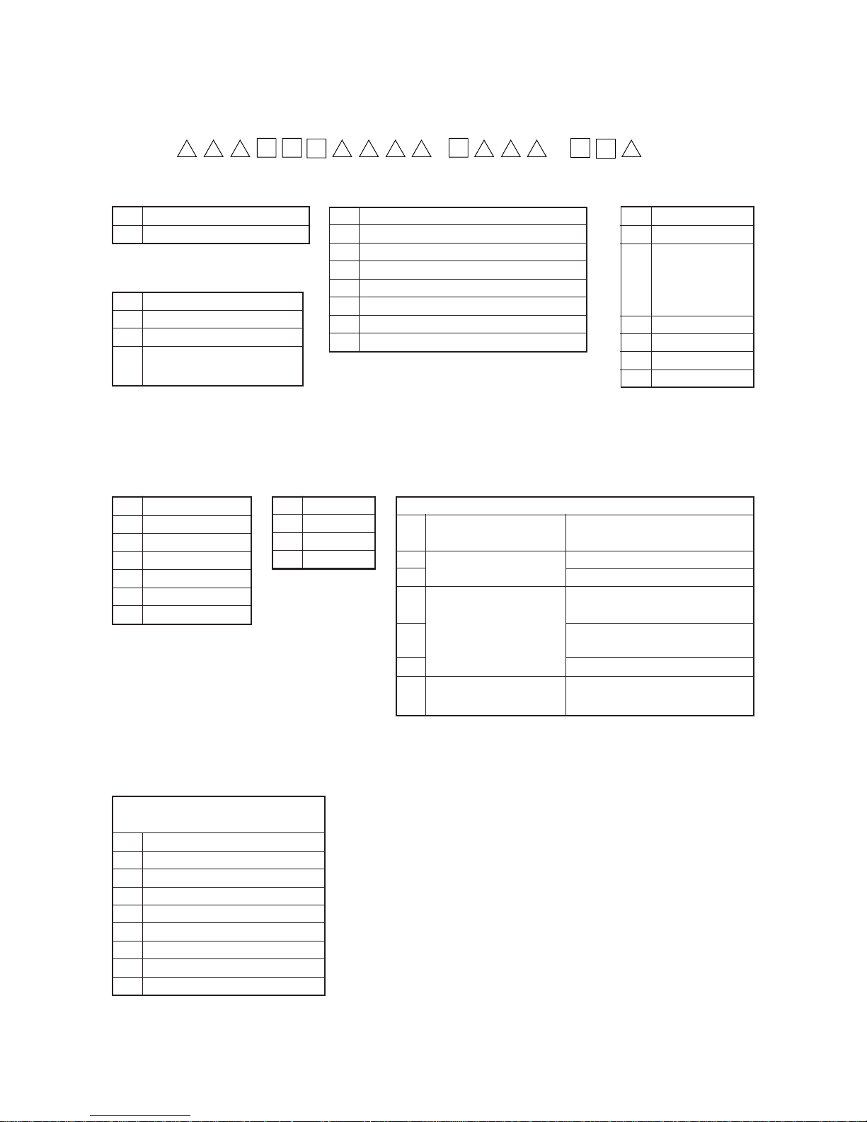
2. MODEL NUMBERING SYSTEM
MO-6000 SERIES MODEL NUMBERING SYSTEM
MO6 / –
1 2 3 4 5 6 7 8 9 10 11 12 1314 15 16 17 18 19 20 21 22
4 Machine code
7 6700 series
9 6900 series
5. 6 Seam code
03 Splicing
04 1-needle 3-thread overlock (504)
05 For blind hemmong (505)
12 2-needle 4-thread mock safety stitch (512)
14 2-needle 4-thread overlock (514)
16 2-needle 5-thread safety stitch (516)
43 3-needle 6-thread safety stitch
45 2-needle double chainstitch
8 Needle gauge code
0 1-needle
B 2.0 mm
C 2.4 mm,
2.6 mm (for extraheavy-weight
materials)
D 3.2 mm
E 4.0 mm
F 4.8 mm
1 4.8 mm + 2.0 mm
7 Basic specification code
S Standard
G Extra heavy-weight materials
R Variable top feed type
J Variable top feed type for
extra heavy-weight materials
9 Overedging width code
A 1.6 mm
D 3.2 mm
E 4.0 mm
F 4.8 mm
H 6.4 mm
M 10.0 mm
N 18.0 mm
10 Feed dog code
4 2-row
5 1-row
6 3-row
7 4-row
12 Application code
Classification based on type of operation
and process
0 Standard
1 For blind stitching
2 For gathering
4 For attaching tape
5 For binding
6 For binding tape
D Splicing *
E Car mattress
F Soft chain
* In case of the splicing, 13th figure is [1].
11 Material code
Classification based on materials to be used
For light-weight materials such as
shirts or the like
Knit wear only
General fabrics
Knit wear only such as sweater or
the like
Medium-weight to heavy-weight
materials such as denim or the like
For heavy-weight materials
Heavy-weight materials for jeans, car
mattress, etc.
1
2
3
4
5
6
7
Extra light-weight to lightweight materials
Light-weight to mediumweight materials
Medium-weight to heavyweight materials
Heavy-weight to extra
heavy-weight materials
* 6900 only
*
*
*
Page 11
−7 −
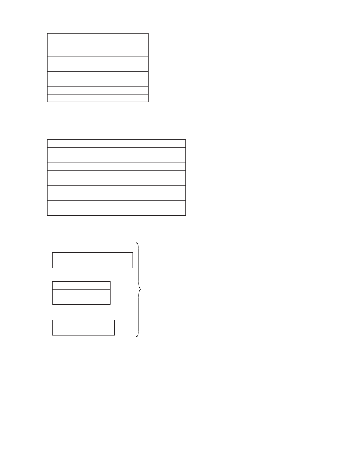
13 Special machine code
Special classification of machine, structure and
specification other than gauge set
0 Standard
6 Feed dog provided with a lip
7 Upper looper high throw type
F For swim suits
H Upper looper extra high throw type
M For zipper
1 For splicing
15 to 18 Device and attachment code
G02/Q141 Presser foot/tape guide for attaching tape
G39/Q141 Presser foot (for sharp curve)/tape guide for
attaching tape
L121 Blind hemming ruler
S159 Swing type ruffler (pedal-interlocking type for safety
stitch)
S161 Swing type ruffler (Manual lever type for safety
stitch)
S162 Swing type ruffler (Manual lever type for overlock)
N077 Four-fold binder
* The general export specification is for Hong Kong, U.S.A., Japan and Singapore.
20 Machine head code
A Standard machine head
(Common to all specifications)
21 Accessory code
A
For general export
*
B For JE
G For China
22 Machine head code
0 Fully-sunken type
1 Semi-sunken type
The numberings after “–” (hyphen) of 19th figure will be used on
and after April 1, 2002. They are not described on the catalogue or the like.
Page 12
−8 −
Standard Adjustment
3. STANDARD ADJUSTMENT
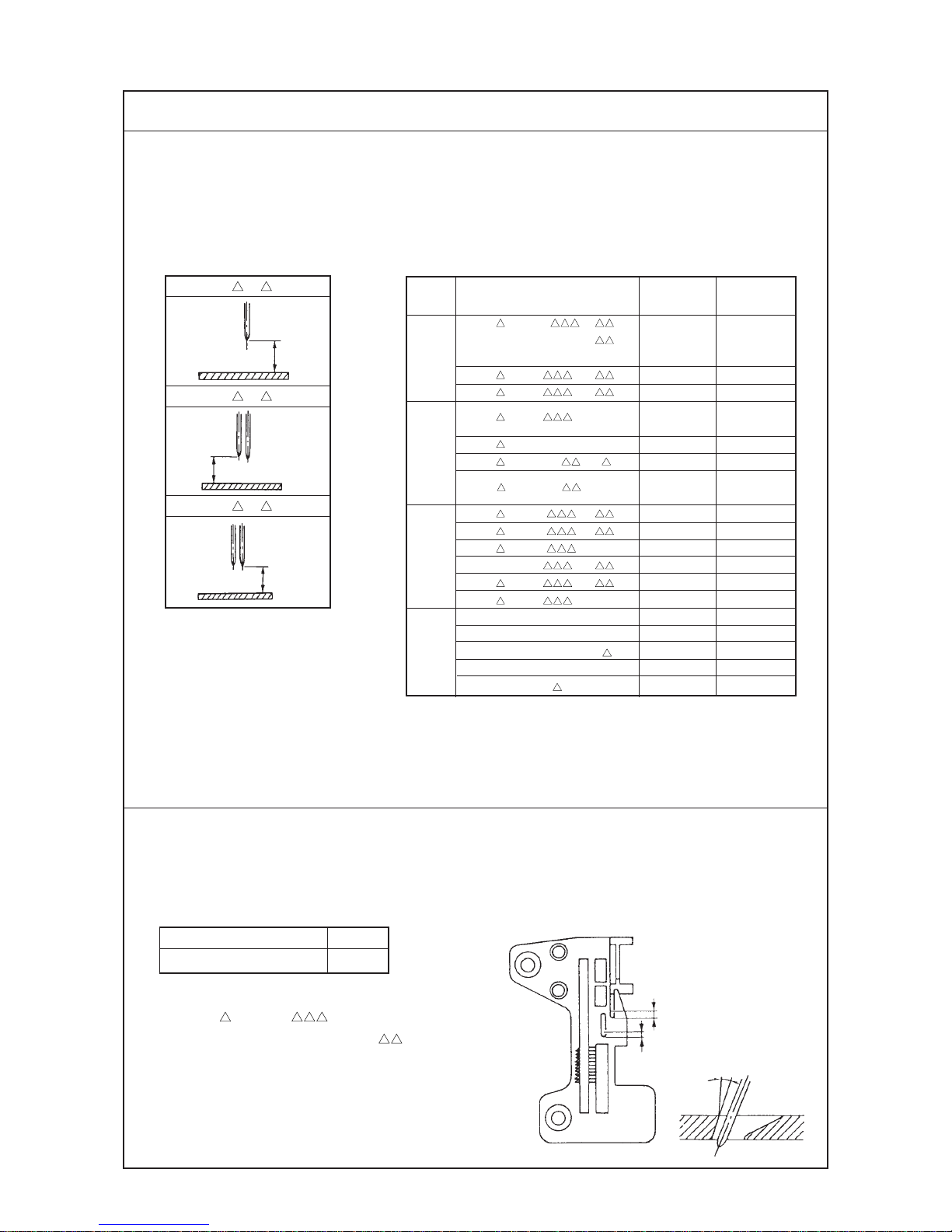
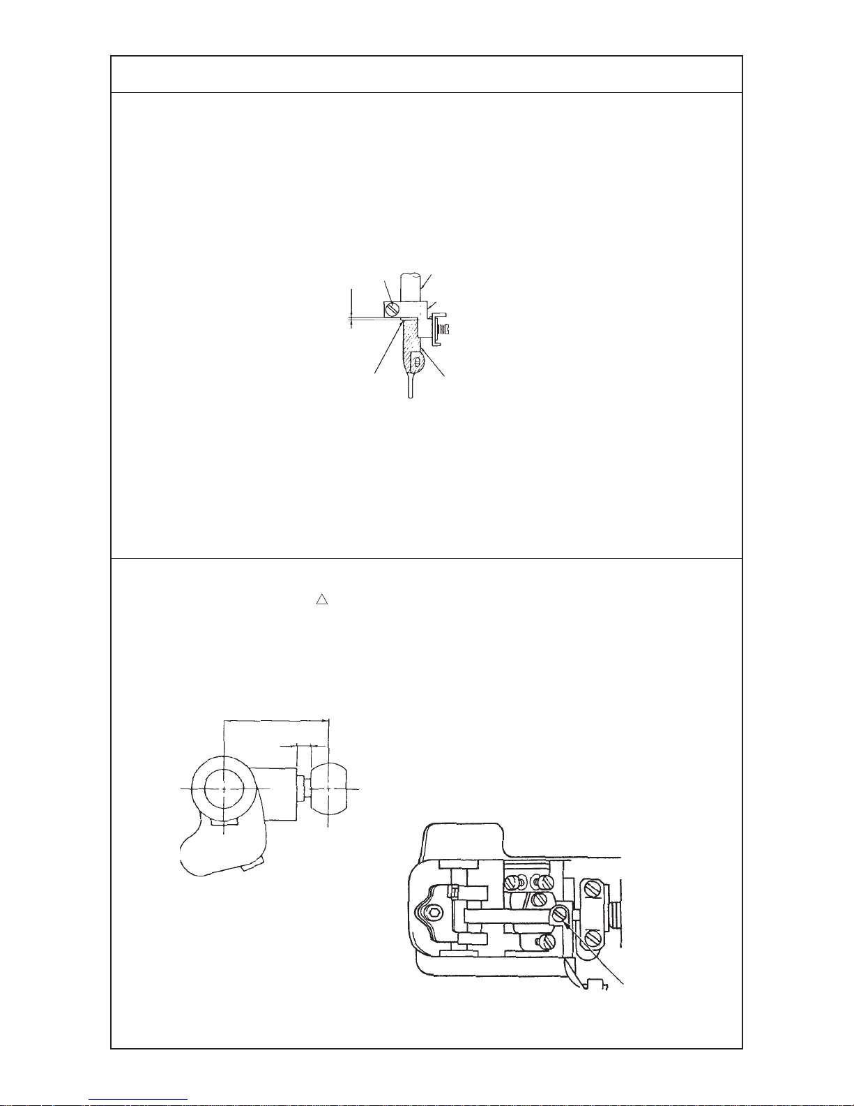
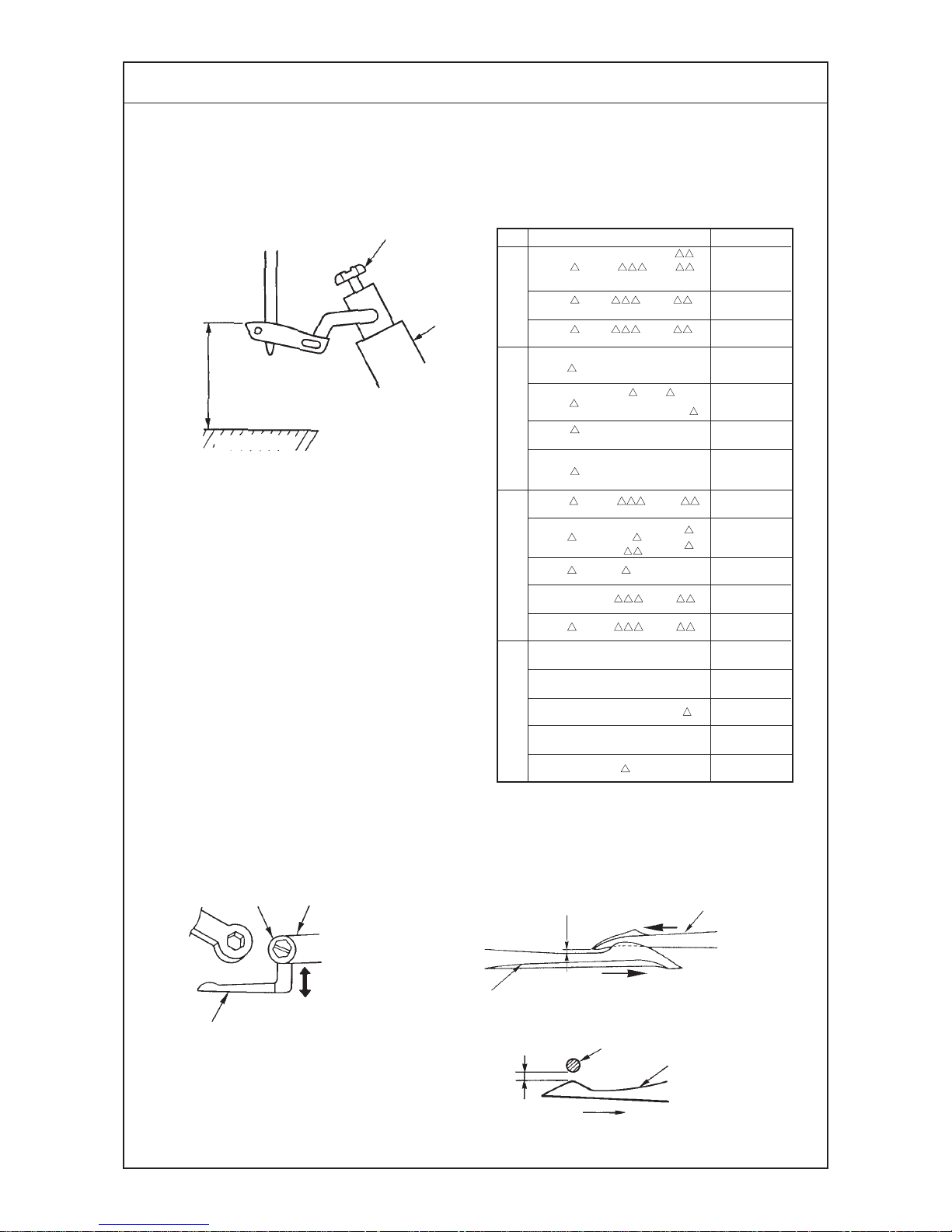
(1) Adjusting the needle height
When the needle(s) is in the highest position,
the needle height from the throat plate surface should be as shown below.
(2) Positioning the throat plate
The needle entry point should be such that the distances listed below are provided between the
needle slot edge of the throat plate and the center of needle.
Note that “A=1.8” and “B=1.5”
for MO-6 16S (R) - -60H,
“A=1.6” and “B=1.3” for MO-69 G, J
(Unit : mm)
Overlock side A 1.3
Double-chainstitch side B 1.0
10˚
A
B
6 04
6 14
6 16
e
1-needle/
2-needle : left
10.5
11.3
11.3
11.0
11.3
10.5
11.3
10.5
11.3
13
10.5
11.3
9.8
15.4
14.4
15.4
14.1
14.1
2-needle : right
–
–
–
9.4
9.9
9.1
9.9
–
–
–
9.9
9.9
–
–
–
–
12.6
–
The adjustment of needle height for the 2-needle
overlock machine should be made in reference to the
left needle.
Model
MO- 6 04S(R) - - 0
- 6
50M
MO- 6 04S - - H
MO- 6 05S - - H
507
50F
MO- 6 12S -CE4 -40H
MO- 6 14S (R) -B -3 7
20H
40H
MO- 6 16S(R)- - 0
MO- 6 16S(R)- - H
MO- 6 16S(R)- -60H
MO- 6943R - - 7
MO- 6 43S - - H
MO- 6 45S - -360
MO- 6903G -0N6 -3D1
MO- 6904G(J)-0F6 -700
MO- 6905G -0M6 -7 0
MO- 6914G(J)-CH6 -700
MO- 6916G(J)-F 6 -700
(Unit : mm)
1-needle
overlock
machine
2-needle overlock
machine
Safety stitch
machine
MO-6900G, J
MO- 6 12S - -
MO- 6 14S (R) -B -
Page 13

−9 −
Adjustment Procedures Results of Improper Adjustment
1) Take off the upper cover, loosen setscrew 2 of needle driving
forked crank 1 and move needle driving forked crank 1 up or
down to adjust the needle height.
(Caution) Do not fully loosen the setscrew 2 of the needle
driving forked crank 1.
If the needle driving forked crank has got out of position
laterally when its setscrew was loosened, fully loosen the
setscrew and turn pulley to allow the forked crank to turn
until it settles by itself. Then tighten the setscrew to fix the
forked crank at that position.
1) Loosen setscrews 2 of throat plate base 1 and move throat
plate base 1 back and forth to adjust dimension A or B.
™ Any other needle height than
specified here will badly affect
the action of the lower looper,
the timing for catching the upper
looper thread, etc.
™ Improper lateral position of the
needle driving forked crank will
cause seizure, play, or other
troubles.
™ Improperly positioned throat
plate will cause needle
breakage, contact of the
needles will the throat plate, or
other troubles.
Needle driving shaft
1
2
1
2
Page 14
−10 −
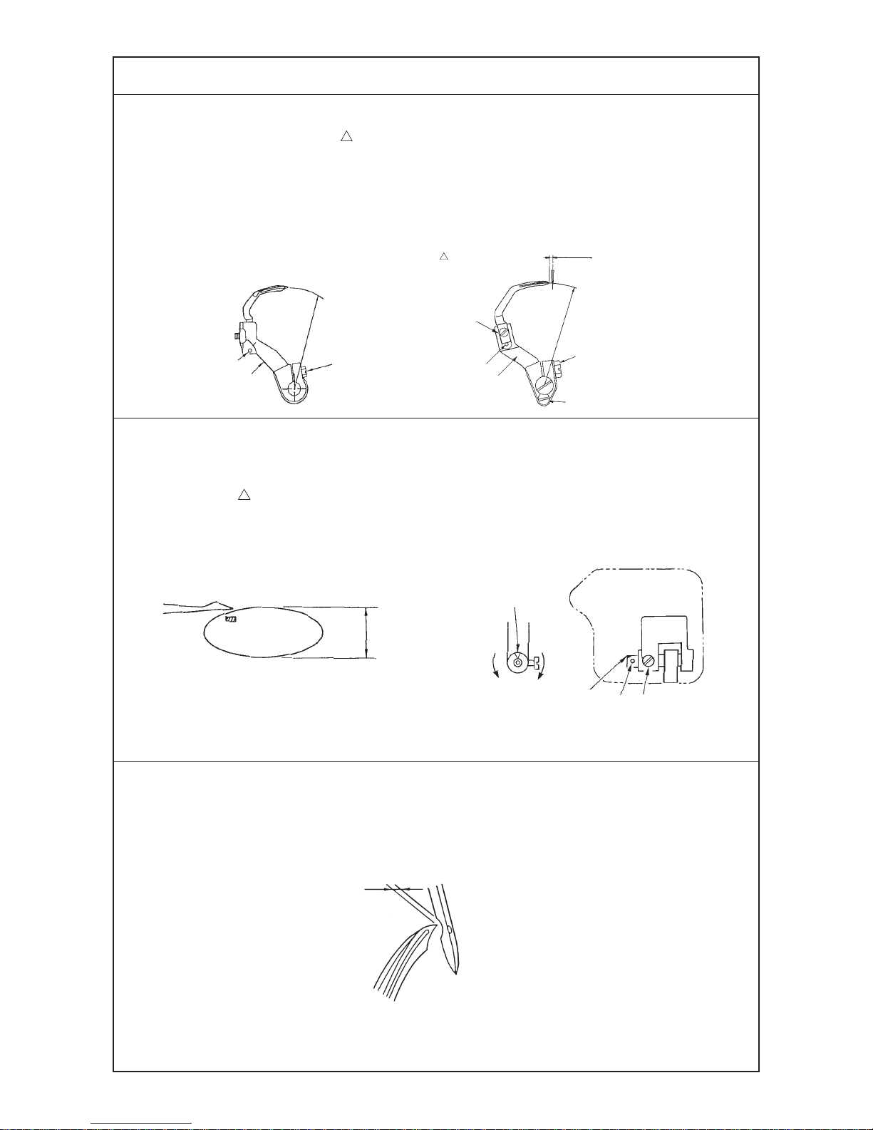
(3) Installing position of the needle clamp
Needle clamp connecting stud 1 should fit with the bottom end of needle bar 2 or spaced within 0 to
0.5 mm.
Standard Adjustment
(4) Adjusting the length of the lower looper holder
(Applicable only to MO-6 16S / MO-6916R, G, J series)
The center-to-center distance should be 26 mm.
At this time, the clearance between the end surface of the arm and the neck of the ball should be
3.5 mm.
3.5 mm
0 to 0.5 mm
Butt the needle clamp with the
bottom end of the needle bar.
26 mm
1
2
3
4
1
Page 15

−11 −
1) Loosen setscrew 3 and adjust, by slightly turning needle clamp
4, the clearance provided between the right-hand side needle
and the lower looper (for 2-needle overlock machine) and the
clearance provided between the needle hole in the throat plate
and the needle (for safety stitch machine).
™ If the clearance provided
between the needle and the
looper is excessive, the needle
thread will be likely to skip at the
time of tucking.
™ If the clearance provided
between the needle and the
looper is insufficient, the needle
will break or the looper blade
point will be damaged causing
thread breakage.
Adjustment Procedures Results of Improper Adjustment
1) Loosen setscrew 1 of the lower looper holder from the rear of
the frame.
Since it is difficult to accurately measure the center-to-center
distance, perform adjustment to provide a 3.5 mm distance
between the end surface of the arm and the neck of the ball as
illustrated.
™ Increasing the center-to-center
distance will give a smaller
stroke of the duble chain looper
or lower looper, and decreasing
the distance will give larger
stroke.
Page 16
−12 −
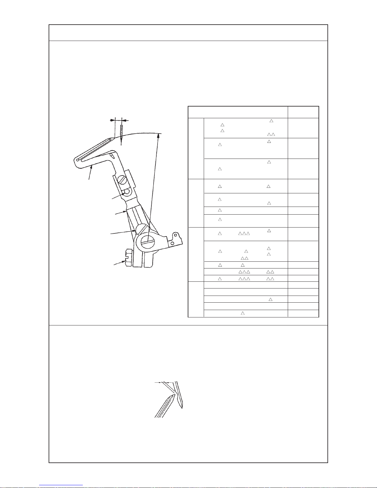
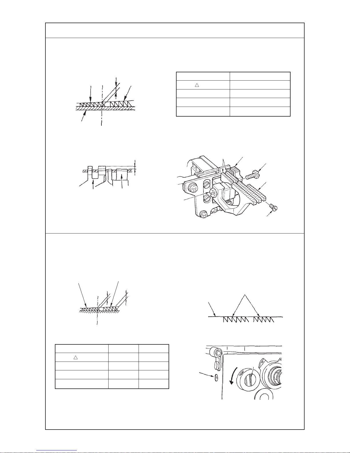
(5) Adjusting the lower looper
1) Returning amount of the lower looper
The distance between the blade point of the
lower looper and the center of the needle
should be as follows when the lower looper is
at the extreme left of its stroke.
2) Clearance between the lower looper and the needle
The clearance should be 0 to 0.1 mm.
Standard Adjustment
Dimension J
4.0
3.7
3.8
3.8
3.8
4.0
2.2
3.7
3.8
2.8
3.8
3.8
1.4
3.5
1.3
3.3
3.5
Model
Safety stitch
machine
K
(66.9±0.2 mm)
0 to 0.1 mm
1-needle overlock
machine
2-needle overlock
machine
MO-
6900G,J
5
(Only MO-69
△△
S,R,
G, J series)
(Unit : mm)
J
1
2
3
4
6 04S(R)
6
05S
MO- 6
04S(R)- -
MO- 6 04S - -
MO- 6
14S(R) - -3 7
MO- 6
16S(R) - -
0A5 15
MO- -0A4 to 0E4 -210
0D6 3
0F4 3 0
0F6 500
0H4 50M
0D4 to 0E4 4
H
0F6
50H
BD4 to BE4
BD6 to BE6
BD6 to BF6 20H
BE7 4
H
MO- 6
12S -CE4 -40H
50F
507
3
0
500
BE4
MO- 6
16S(R) -DD -
F
MO- 6 16S(R) -F 6 -60H
MO- 6943R -
- 7
MO- 6
43S - - H
MO- 6903G -0N6 -3D1
MO- 6904G(J) -0F6 -700
MO- 6905G -0M6 -7
0
MO- 6914G(J) -CH6 -700
MO- 6916G(J) -F
6 -700
MO- 6
12S -DF6 -
MO- 6
14S(R) -
4 H
5
H
Page 17

−13 −
Adjustment Procedures Results of Improper Adjustment
™ Excessive return of the lower
looper tends to cause stitch
skipping when filament thread is
used.
™ Insufficient return of the lower
looper tends to cause needle
thread stitch skipping when
spun thread is used.
™ Excessive clearance will often
cause needle thread stitch
skipping.
™ Insufficient clearance will cause
needle breakage due to the
contact of the looper with the
needle, or produce scratches on
the blade point of the looper,
leading to needle thread
breakage or other troubles.
1) Returning amount of the lower looper
1 Loosen setscrew 2 of lower looper support arm 1 and adjust
lower looper 4 to make adjustment of the returning amount.
(Referential information)
1. Radius K of lower looper 4 will be 66.9 mm when the lower
looper is inserted into lower looper support arm 1 until it
contacts with stopper pin 3 and then is fixed.
2. The rocking angle of the lower looper will be 26˚.
(MO-6 S, R)
The rocking angle of the lower looper will be 32˚.
(MO-69 G, J)
2) Clearance between the lower looper and the needle
MO-6700S Series
1 Loosen setscrew 2 of lower looper support arm 1 to the extent
that it is temporarily tightened. Now, make the adjustment by
moving lower looper support arm 1 back and forth.
MO-6900S, R, G, J Series.
1 Loosen setscrew 2 of lower looper support arm 1 to the extent
that it is temporarily tightened. Then finely adjust the longitudinal
position of the looper using fine adjustment screw 5.
2 Turn fine adjustment screw 5 clockwise to move lower looper
4 away from the needle.
Turn the screw counterclockwise to move lower looper 4 closer
to it.
Page 18
−14 −
Standard Adjustment
Model
6 04S(R)
6
05S
MO- 6
04S(R)- -
(6) Position of the upper looper guide
Vertical position :
To be in close contact with the frame guide surface.
Laternal position :
To be pressed against the upper looper guide support
gauge 1.
Safety stitch machine
1-needle overlock machine
2-needle overlock machine
6
5.8
Upper
looper
guide
support
gauge
13131909 13132006
Model
MO-6900G, J
7
6.3
5.8
6
5.8
4.7
5.5
6.3
5.8
5.8
5.8
4
4.2
4
4.2
4.2
11545100 12375606
7 5.5
6.3
4.7
4.2
4
Maker dot
(Unit : mm)
(Unit : mm)
(Unit : mm)
3 0
500
BE4
MO- 6
16S(R) -DD -
F
MO- 6 16S(R) -F 6 -60H
MO- 6943R -
- 7
MO- 6
43S - - H
MO- 6903G -0N6 -3D1
MO- 6904G(J) -0F6 -700
MO- 6905G -0M6 -7
0
MO- 6914G(J) -CH6 -700
MO- 6916G(J) -F
6 -700
1
2
3
4
G
Frame guide surface
Dimension G Dimension G
0A5 15
MO- -0A4 to 0E4 -210
0D6 3
0F4 3 0
0F6 500
0H4 50M
0D4 to 0E4 4
H
0F6
50H
BD4 to BE4
BD6 to BE6
BD6 to BF6 20H
BE7 4
H
MO- 6
12S -CE4 -40H
507
50F
MO- 6
04S - -
MO- 6
14S(R)- -3 7
MO- 6
14S(R)- -
MO- 6 12S -DF6 -
MO- 6
16S(R) - -
4
H
50H
6
Page 19

−15 −
Adjustment Procedures Results of Improper Adjustment
1) Fit upper looper guide support gauge 1 over gauge fixing pin
3 which has been driven in frame 2 and secure the gauge
with an O ring.
Then position the gauge taking the marker dot engraved on it
or the chamfering direction as reference.
2) When installin upper looper guide support 4, press it against
the gauge while keeping the upper looper guide support into
close contact with the frame guide surface, then tighten the
screws.
(Caution) Refer to “4- (4) -1) - 7 Various sealants” for the
various sealants.
™ If the upper looper guide has
improperly positioned vertically,
it will cause oil leakage or
disturbed path of the upper
looper with resultant stitch
skipping.
™ If the upper looper guide has
been inaccurately positioned
laterally, it will cause stitch
skipping, or contact with the
looper.
Page 20
−16 −
Standard Adjustment
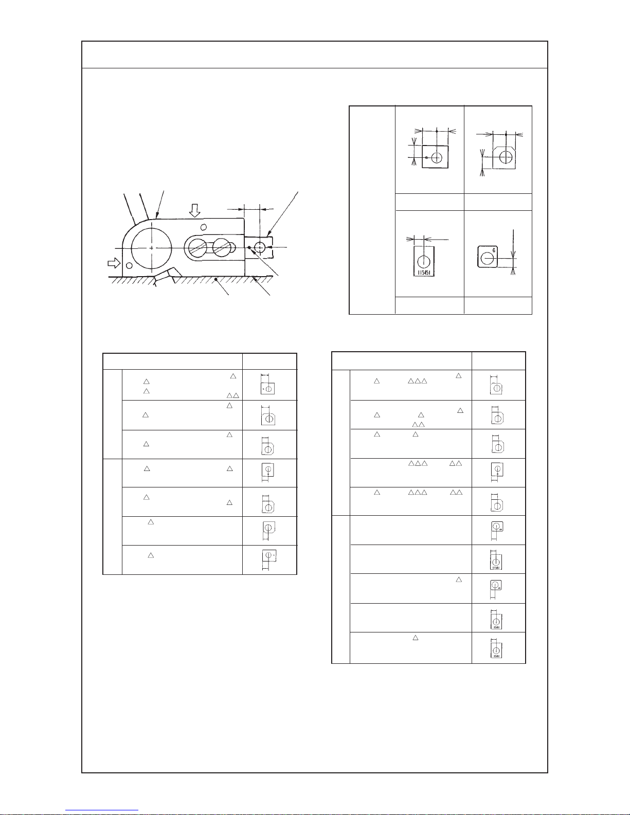
(7) Positioning the upper looper holder
The distance between the bottom surface of the frame and the upper end of the upper looper holder
pin 2 should be as shown below when the upper looper holder 1 is at the highest point of its stroke.
F
Bottom surface of frame
53 mm
1
2
3
4
5
6
1
4
0.2mm
0.2mm
Model
6 04S(R)
6
05S
MO- 6
04S(R)- -
Safety stitch machine
1-needle overlock machine
2-needle overlock machine
MO-6900G,J serise
Dimension F
45.0
46.2
48.2
47.3
48.4
46.8
46.9
46.2
48.2
48.4
47.3
48.4
51.2
50.7
51.7
49.3
48.8
(Unit : mm)
MO- 6 14S(R)- -3 7
MO- 6 14S(R)- -
MO- 6
12S -DF6 -
0A5 15
MO- -0A4 to 0E4 -210
0D6 3
0F4 3 0
0F6 500
0H4 50M
0D4 to 0E4 4 H
0F6
50H
BD4 to BE4
BD6 to BE6
BD
to BF 20H
BE7 4
H
MO- 6
12S -CE4 -40H
507
50F
MO- 6
16S(R)- -
3
0
500
BE4
MO- 6
16S(R)- DD -
F
MO- 6 16S(R)-F 6 -60H
MO- 6943R -
- 7
MO- 6
43S - - H
MO- 6903G -0N6 -3D1
MO- 6904G(J)-0F6 -700
MO- 6905G -0M6 -7
0
MO- 6914G(J)-CH6 -700
MO- 6916G(J)-F
6 -700
4
H
5 H
MO- 6 04S - -
Page 21

−17 −
Adjustment Procedures Results of Improper Adjustment
1) Loosen the setscrew of upper looper ball arm 3 and setscrew
5 of the upper looper holder.
2) Adjust the clearances between upper looper bracket 4 and
upper looper holder 1 to approximately 0.2 mm respectively,
and tighten setscrew 5 of the upper looper holder.
(Make sure that the upper looper holder smoothly moves
together with upper looper shaft 6.)
3) Then determine dimension F from the bottom surface of the
frame to the top surface of upper looper holder pin 2 before
tightening the setscrew of upper looper ball arm 3.
(Caution) Replace upper looper holder 1 according to the
needle gauge size.
™ Inaccurately positioned upper
looper holder will cause
excessive projection of the
upper looper, resulting in stitch
skipping, or other troubles.
(Caution) To adjust the upper
looper ball arm, take
dimension F as standard.
Remember that the projecting
amount and the height of the
upper looper should
eventually be properly
adjusted. So, confirm the
dimensions related to the
upper looper.
Page 22
−18 −
Standard Adjustment
(8) Positioning the upper looper
1) Height of the upper looper
The distance between the throat plate surface and the blade point of the looper should be as follows
when the upper looper is at the extreme left of its travel.
2) Longitudinal position of the upper looper
1 The clearance between the upper
and lower loopers should be 0.1 to 0.2 mm
when they cross with each other.
2 The clearance between the upper looper 3
and the needle should be 0 to 0.2 mm.
Model
Safety stitch machine
1-needle overlock
machine
2-needle overlock
machine
MO-6900G,J series
Dimension D
11.0
11.3
11.3
10.3
11.0
11.8
11.0
11.0
11.3
12.8
10.3
11.0
13.6
13.7
12.0
12.9
13.7
0
MO- 6
04S(R)- - 6
50M
MO- 6
04S - - H
MO- 6
05S - - H
BD4 to BE4
BD6 to BE6
BD
to BF 20H
BE7 4
H
MO- 6
12S -CE4 -40H
507
50F
MO- 6 16S(R) - - 0
MO- 6 14S(R)- -307
BE4
MO- 6 16S(R)- DD -
F
MO- 6 16S(R) - F 6 -60H
MO- 6943R
- - 7
MO- 6 43S
- - H
MO- 6903G -0N6 -3D1
MO- 6904G(J) -0F6 -700
MO- 6905G -0M6 -7 0
MO- 6914G(J) -CH6 -700
MO- 6916G(J) -F
6 -700
4
H
5 H
D
Throat plate
(Unit : mm)
1
2
MO- 6 12S -DF6 -
1
2
3
Lower looper
3
0.1 to 0.2mm
0 to 0.2mm
Needle
3
MO- 6 14S(R)- -
Page 23

−19 −
Adjustment Procedures Results of Improper Adjustment
1) Height of the upper looper
1 Set a hexagon screwdriver onto setscrew 2 at the end of upper
looper bracket 1 to adjust height D.
2 When adjusting the height, pay attention also to the clearance
produced between the upper looper and the lower looper at
the time of their crossing.
2) Longitudinal position of the upper looper
1 Loosen setscrew 2 at the top end of upper looper bracket 1
to move upper looper 3 back or forth for positioning the
clearance of 0.1 to 0.2 mm between the upper looper and the
lower looper at the time of their crossing or the clearance of 0
to 0.2 mm between upper looper 3 and the needle.
™ If the upper looper has been
positioned too high, an
excessive clearance will be
produced between the upper
looper and the needle. As the
result, the upper looper thread
will fail to catch the needle
thread, and stitch skipping
occurs.
™ On the contrary, if the upper
looper has been positioned too
low, the needle point will hit the
looper, causing needle
breakage. Also the looper will
touch other component when
the presser foot goes up.
™ Excessive clearance will cause
stitch skipping.
™ Insufficient clearance will cause
the upper looper to come in
contact with the lower looper.
Page 24
−20 −
Standard Adjustment
(9) Adjusting the double chain looper
(Applicable only to MO-6 16S/6916R, G, J series)
1) Returning amount of the double chain looper
The distance between the needle center and the blade point of the double chain looper should be 1.5
to 2 mm when the looper is at the extreme left of its travel.
2) Longitudinal motion (Avoid motion)
The standard minor axis of the elliptical motion should be :
3.0 mm (MO-6 16S, R).
3.5 mm (MO-6916G, J).
Note : The avoid motion should be adjusted in accordance with Needle No.
3) Clearance between the double chain looper and the needle
The clearance should be 0.05 to 0.1 mm.
3.0 to 3.6 mm
0.05 to 0.1 mm
MO-6916G, J series MO-6 16S, R series
Marker
Marker
Hole 5
A
B
M
63.2 mm
1
2
3
M
(63.4 mm)
1.5 to 2 mm
6
1
2
3
4
Page 25
−21 −
Adjustment Procedures Results of Improper Adjustment
™ Excessive return of the double
chain looper will cause frequent
stitch skipping when filament
thread is used.
™ Insufficient return of the double
chain looper will cause frequent
thread stitch skipping when a
spun thread is used.
™ If the avoid motion is too large,
triangle stitch skipping will often
occur.
™ Insufficient avoid motion will
cause the needle point to hit the
looper, producing scratches on
the needle point or looper.
™ Excessive clearance will cause
frequent needle thread stitch
skipping.
™ Insufficient clearance will cause
to looper to hit the needle,
leading to needle breakage or
scratches on the looper blade
point with consequent thread
breakage.
1) Returning amount of the double chain looper
1 Loosen setscrew 2 of double chain lopper driving arm 1 to
make this adjustment.
2 Radius M of the double chain looper driving arm 1 will be
63.4 mm when it is lowered until it comes in contact with stopper
pin 3.
3 For MO-6916G,J type machines, radius M will be 63.2 mm.
4 Adjust the tilt of double chain looper with setscrew 4. Adjust
the tilt to 1.6 mm.
2) Longitudinal motion (Avoid motion)
1 Open the cover of the adjusting hole on the rear of the frame,
loosen setscrew 5, and put a ø2 rod in the hole. Now, make
the adjustment by turning the rod back and forth.
Marker : This side
..... Minimum (for standard to thin needle) A
Marker : Far side
..... Maximum (for thick needles) B
3) Clearance between the double chain looper and the needle
1 Temporarily tighten setscrew 2 in the double chain looper,
and finely adjust the longitudinal position of the double chain
looper. Adjust the clearance to 0.05 to 0.1 mm.
MO-6916S,R series only
2 Turn fine adjustment screw 6 clockwise to move the double
chain looper away from the needle.
Turn it counterclockwise to move the double chain looper closer
to it.
Good needle
entry
Bad needle
entry
1.6mm
4
As observed
from this side
Page 26
−22 −
Standard Adjustment
(10) Adjusting the height and clearance of the needle guard
1) For 1-needle or 2-needle overlock machine
Make needle guard A lightly come in contact with the top end of needle (bend needle by 0 to 0.05
mm) when the blade point of the lower looper reaches the needle center.
The clearance between needle guard B and the needle is 0.1 mm when the needle is at the lowest
point of its stroke.
The height of needle guard B is 1 mm from the throat plate bottom surface.
2) For safely stitch machine
The safely stitch machine has four needle guards, A, B, C and D. The needle guards A and B are
positioned in the same manner as those for the overlock machine.
The needle guard C should be positioned 5 mm below the throat plate bottom surface.
Needle guard A
(Traveling needle guard)
Light
touch
the
needle
guard
A
Needle guard B
Throat plate
1 mm
0.1 mm
B
B
C
D
Throat plate
5 mm
Lightly touches
0.1mm
1
2
3
2
3
4
5
Page 27

−23 −
Adjustment Procedures Results of Improper Adjustment
1) For 1-needle or 2-needle overlock machine
1 Adjust needle guard A with setscrews 1 in the needle guard
so that it lightly comes in contact with the needle (bend needle
by 0 to 0.05 mm) when the blade point of the lower looper
reaches the needle center.
2 To adjust the clearance provided between needle guard B and the
needle when the needle bar is at the lowest point of its stroke, loosen
setscrews 2 in the needle guard support and turn needle guard B
to adjust the clearance to 0.1 mm.
3 Adjust the height of needle guard B to 1 mm from the throat plate
bottom surface with setscrew 3 in the needle guard.
2) For safety stitch machine
1 Loosen setscrews 4 in the needle guard, and adjust the
clearance provided between needle guard C and the needle
so that it lightly comes in contact with the needle (bend needle
by 0 to 0.05 mm).
2 Adjust the installing height of needle guard C to 5 mm with setscrew
3 in the needle guard.
3 Adjust the clearance provided between needle guard D and the
needle to 0.1 mm with setscrews 5.
(Caution) Check again the clearance provided between needle
guard B and the needle after adjusting the height of needle
guard C.
™ Excessively close contact between
the needle guard A and the
needles will lead to needle bend
or stitch skipping.
™ A clearance left between the
needle guard A and the needles
will cause the looper blade point to
come in contact with the needles,
leading to needle or blade point
breakage, or other troubles.
™ If the needle guard B is too high,
thread loops will be damaged with
resultant stitch skipping. Also,
double chain loops will be affected,
causing double chain stitch
skipping.
™ If the needle guard B is too low,
the needle cooling felt will be
lowered, resulting in deteriorated
effect of the cooling and needle
guard.
™ Excessive clearance between the
needle guard B and the needle will
cause stitch skipping due to needle
shake. On the contrary, insufficient
clearance will cause the needle
guards to catch the needles
between them, leading to wear on
the needle guards and scratches
on the needles.
™ If the needle guard C is too high,
the needle thread loops will be
damaged, and stitch skipping
occur. If it is too low, the needle
points will be crushed.
™ If the clearance between the
needle guard C and the needles
is too large, the double chain looper
blade point will come in contact with
the needles, causing the breakage
of the needles, causing the
breakage of the needles or looper
blade point.
No clearance left between them will
cause them to come in excessively
close contact with each other, and
wear on the needle guard and
scratches on the needles will occur.
™ Excessive clearance left between
the needle guard D and the
needles will cause stitch skipping
due to needle shake, and
insufficient clearance will cause the
needle guards to catch the needles
between them, leading to wear on
the needle guards and scratches
on the needles.
Page 28
−24 −
Standard Adjustment
(11) Adjusting the height of the feed dog
The height of main feed dog 2 from the top surface of the throat plate 1 should be as follows when
it is at its highest posion.
Auxiliary feed dog 4 is 0.5 mm lower than main feed dog 2.
(12) Adjusting the tillt of the feed dog
Model Dimension A
MO-6 00S Series 1.0
MO-6904G Series 1.3
MO-6914G Series 1.2
MO-6916G Series 1.1
0.5 mm
Tilt of the feed dogs when the feed dogs
have come up most.
When the feed dog juts out the top surface of
the throat plate
A
B
Needle
entry
Top surface of
the throat plate
Feed dog is
leveled.
Model Dimension A Dimension B
MO-6 00S Series 1.0 (1.2)
MO-6904G Series 1.3 (1.5)
MO-6914G Series 1.2 (1.4)
MO-6916G Series 1.1 (1.3)
(Unit : mm)
Front up
1
2
3
A
Needle
entry
2
3
4
5
6
7
2
4
2
3
9
8
(Unit : mm)
Page 29

−25 −
Adjustment Procedures Results of Improper Adjustment
1) Adjust the height of main feed dog 2 to dimension A with
setscrew 5.
2) Adjust the height of differential feed dog 3 with setscrew 7 so
that there is no difference in level between main feed dog 2
and differential feed dog 3.
3) Adjust the height of auxiliary feed dog 4 with setscrew 6 so
that it is 0.5 mm lower than main feed dog 2.
1) Use the tilt of the feed dog when it is in its highest position as a
reference and adjust so that the feed dog is flush with the throat
plate when the feed dog juts out the throat plate.
2) Feed bar shaft 8 consists of an eccentric shaft. Loosen
setscrew 9 to perform adjustment.
When the marker line is set at middle
.....The feed dog will be flat.
When the marker line is set at bottom
.....The feed dog will be tilted with its front up (in the arrowed
direction).
When the marker line is set at top
.....The feed dog will be tilted with its front down.
(Caution) The marker line should be used just as the reference
since it slightly differs with that of each machine due to
the disparity of the components.
Confirm the accurate tilt of the feed dog by observing the
feed dog itself.
™ If the feed dogs are too high, the
needles will be deflected and
broken when sewing heavyweight materials. The feed dogs
will tend to suffer scratches
when sewing light-weight
materials. Puckering will
frequently occur.
™ If the feed dogs are too low,
insufficient feed power will
result.
™ If the auxiliary feed dog is too
high, chain-off thread will be
often jammed.
™ If the main feed dog and
differential feed dog are set at
different heights, proper
differential feeding action will be
hindered.
™ When tilted with the front up
Good material catching will be
obtained.
™ When tilted with the front down
Uneven feed and puckering will
be effectively prevented.
Page 30

−26 −
Standard Adjustment
(13) Adjusting the differential feed ratio
(Max, gathering)
Gathering: 1: 4
Stretching: 1: 1.3
Center
of nut
Lower
marker
line
(Standard)
Gathering: 1: 2
Stretching: 1: 0.7
Pin at its highest
position
(Max, stretching)
Gathering: 1:1.6
Stretching: 1:0.6
Washer
Pin at its
lowest
position
MO-6900G, J Serise
Center of nut
(MO6904G (J), MO6916G (J))
Gathering: 1: 1.75
Stretching: 1: 0.6
(MO-6914G (J))
Gathering: 1:2.0
Stretching: 1:0.7
Center of nut
Halfway
between
upper
marker line
and lower
marker line
Slightly
lower than
lower
marker line
MO-6000S, R Serise
1
23
4
2
3
4
2
3
4
(14) Longitudinal position of the feed dog
When the feed pitch is maximized and the differential feed ratio is also maximized, the clearances of
the front and rear ends of the feed dog, and the throat plate should be spaced approximately 0.5 mm
respectively.
0.5mm
0.5mm
1
2
Page 31

−27 −
Adjustment Procedures Results of Improper Adjustment
1) Remove cover 1 on the rear of the frame and loosen main
feed pin and nut 3.
2) Move main feed pin 2 up or down to adjust the differential
feed ratio.
3) Adjust so that the lower engraved marker line on main feed
rocker 4 aligns with the center of nut 3. (Standard)
4) When adjusting the maximum stretching, adjust main feed pin
2 to the highest position.
5) When adjusting the maximum gathering, adjust main feed pin
2 to the lowest position.
6) After performing adjustment, tighten the main feed pin and nut
3, and install cover 1.
1) Remove the cover on the rear of the frame, loosen main feed
bracket clamping screw 1 and differential feed bracket
clamping screw 2, and adjust the clearances provided between
the front and rear ends of the feed dogs and the slots in the
throat plates to approximately 0.5 mm. Then tighten main feed
bracket clamping screw 1 and differential feed bracket
clamping screw 2.
™ If the clearance provided
between the throat plate and the
feed dog is too small, they will
come in contact with each other
when the sewing machine runs
at high speed.
Page 32

−28 −
Standard Adjustment
(15) Adjusting the presser foot
1) Adjusting the tilt of the presser foot
The presser foot should be positioned so that the feed dogs go down under the specified presser foot
pressure, and the presser foot sole comes in contact evenly with the throat plate surface.
2) Adjusting the micro-lifting mechanism of the presser foot
Throat plate
1
2
3
Page 33

−29 −
Adjustment Procedures Results of Improper Adjustment
1) Adjusting the tilt of the presser foot
1 Turn the handwheel and place the feed dog in the position
where the feed dog does not jut out the top surface of the throat
plate.
2 Loosen setscrew 1 and adjust so that the presser fopot sole
comes in contact evenly with the throat plate top surface. Then
tighten setscrew 1.
(Reference) Accurate adjustment can be made by using two
pieces of thin paper to check for even drawing-out tension.
In addition, even contact of the presser foot with the throat
plate top surface is achieved rather easily by tightening
the screw while pushing the right side of the presser foot.
2) Adjusting the micro-lifting mechanism of the presser foot
1 When moving presser lifting lever 2 just a little, perform it with
fine adjustment screw 3.
™ Uneven contact will result in bad
straight material feed, weak feed
power, or puckering.
Page 34

−30 −
Standard Adjustment
(16) Positioning the upper knife arm shaft
The upper knife shaft should be positioned 34 mm above the top surface of the throat plate when it is
at its highest position.
MO-6 16S(R)-F 6-60H : 35 mm
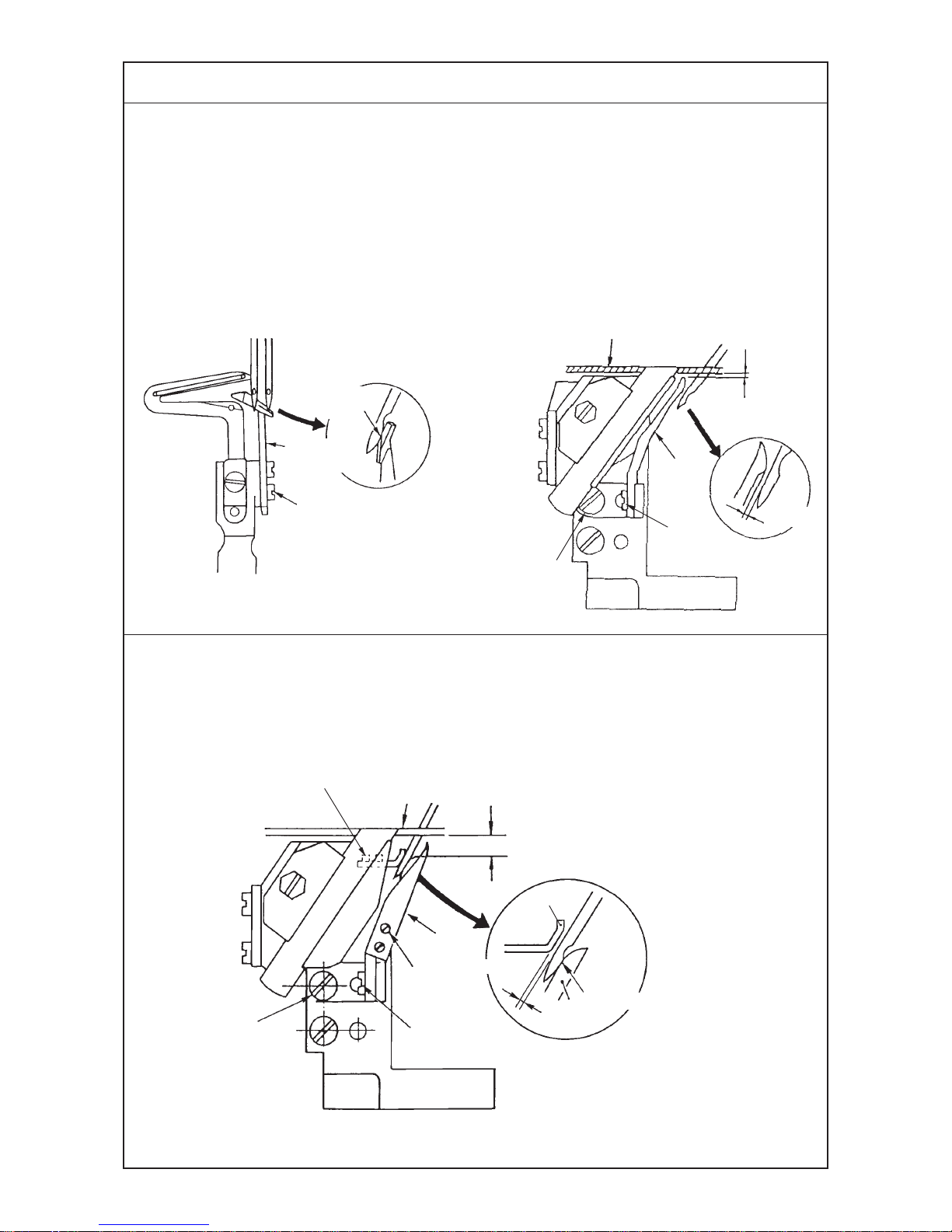
(17) Positioning the upper and lower knives, and available overedge widths
1) Lower knife
2) Upper knife
3) Overedging width
Overedging width can be adjusted from 1.6 to 6.4 mm.
34 mm
Throat plate
Lower knife
Upper knife
1
2
34
1
2
3
0.5 to 1 mm
Page 35

−31 −
Adjustment Procedures Results of Improper Adjustment
1) Remove the upper cover, loosen setscrew 2 in upper knife
driving arm 1, and turn upper knife shaft 3 to adjust the position
from the top surface of the throat plate to 34 mm.
(Caution) Be sure to fully tighten the setscrew since upper
knife shaft 3 is subjected to high load.
1) Lower knife
1 Adjust the vertical position of the lower knife by screw 1 so
that the blade top aligns with the top surface of the throat plate.
2 Tighten screw 2 after bringing the upper knife to its lowest
position of its stroke.
2) Upper knife
1 Adjust the position of the upper knife by screw 4 so that the
engagement with the lower knife is 0.5 to 1 mm when the upper
knife is in the lowest position of its stroke.
(Caution) Adjust the lateral position of the lower knife by screw
2. Adjust the lateral position of the upper knife by screw
3. After performing adjustment, be sure to fix the knife.
Otherwise, the durability of the knife will be affected.
3) Overedging width
1 Adjust the overedging width in the following way :
Laterally position the upper knife before loosening screw 2.
Tighten screw 2 when the upper knife has settled by itself
under the pressure applied by the spring. Repeat this
adjustment procedure to obtain desired overedging width.
™ Improperly positioned upper
knife arm shaft will come in
contact with the frame.
If it is moved with the position of
the upper knife unchanged,
proper engagement of the
knives will be disturbed,
prohibiting sharp cutting of the
knives.
™ The lower knife, if positioned too
high, will catch materials or
cause no contact of the presser
foot with the throat plate top
surface.
™ If the lower knife is positioned
too low, the cutting width will be
changed or materials will be
caught by the lower knife.
™ The upper knife, if positioned too
high, will fail to cut materials.
™ Unsharp cutting or abnormal
wear on the knives will result
unless the lower knife is laterally
positioned and fixed at a position
where it has settled by itself
under the upper knife spring.
Page 36

−32 −
Standard Adjustment
(18) Resharpening of the knife
(19) Position of the thread cam (Applicable only to MO-6 16 series)
1) Adjustment of the thread cam
2) Adjusting looper thread cam thread guides A and B and the looper thread cam nail
MO-6 16 series
Lower knife gauge
Part No. 11996907
10˚
55˚
Level
1
1
Level
5
6
7
4
2
4
3
Page 37

−33 −
Adjustment Procedures Results of Improper Adjustment
1) When the knives have become dull, fully resharpen lower knife
1 until the contact mark of it disappears.
2) When the upper knife has become dull, replace it with a new
one. (This is because the upper knife is a serrated carbide
knife.)
1) Adjusting the thread cam
1 Adjust the position of the thread cam by its setscrew 1 with
the needles at their upper dead point so that the straight section
of the thread cam is leveled.
2 Laterally position the thread cam so that the looper thread cam
nail is located at the center of the thread cam groove.
[How to check for proper positioning]
Check that the thread cam releases the looper thread when the
needle tip begins to come out of the bottom surface of the throat
plate by 0 to 1 mm.
2) Adjusting the looper thread cam thread guides A and B
and the looper thread cam nail
1 Install looper thread cam thread guides A 2 and B 3 at the
center of the slots with setscrews A 4 and B 5.
2 Install looper thread cam nail 6 with setscrew 7 so that the
straight section of the forked portion is leveled.
™ If the 10˚ angle of the lower knife
is exceeded, the durability of the
knife will be deteriorated, often
resulting in blade chipping.
™ If the angle is smaller than 10˚,
the knife will be dull.
™ If the 55˚ angle is not observed,
the knife may catch materials.
™ If the timing of the thread cam
is too early, the needle point will
fail to enter a thread triangle,
resulting in looper thread stitch
skipping.
™ If the timing of the thread cam
is too late, puckering and loose
looper thread stitches will
results.
™ If the chain looper thread guide
is moved away from you, the
take-up amount of the lower
looper thread will decrease. In
this case, puckering may result
there by impairing the feeling of
the finished product.
0 to 1 mm
Thread
Throat plate
Page 38

−34 −
Standard Adjustment
(20) Adjusting the throat plate support
(21) Adjusting the feed mechanism cover presser
Uniform contact
(22) Adjusting the looper cover
™ The looper cover should smoothly close without coming in contact with upper knife 1 when slowly
closing looper cover 2 with upper knife 1 in its lowest position of its troke.
Frame
1
2
1
2
1
2
3
5
3
2
4
Cloth chip
cover
3
Page 39

−35 −
Adjustment Procedures Results of Improper Adjustment
1) Loosen setscrews 1 and adjust so that throat plate support 2
should not come in single-sided contact but come in uniform
contact with throat plate 3 using setscrews 1.
1) Loosen setscrew 1 and press feed mechanism cover presser
2 in the direction of arrow.
2) Press feed mechanism cover 3 and tighten setscrew 1 so
that the feed mechanism cover should not rise.
(Caution) Check that feed mechanism cover 3 is pressed so
that it should not rise.
™ If the throat plate support comes
in single sided contact with the
throat plate or does not come in
contact with it, the throat plate
will vibrate severely.
™ If the feed mechanism cover is
not fully pressed and the cover
rises, oil leakage will be caused.
1) Close looper cover 2, loosen setscrew 3, and move looper
cover guide plate 4 back and forth until the looper cover is
brought to a position where the cover smoothly closes.
2) Move looper cover guide plate 4 until it slightly comes in contact
with looper cover receiving bracket 5. Now, fix the guide plate
by tightening setscrew 3.
Page 40

−36 −
Standard Adjustment
(23) Adjusting the cloth chip cover
™ When cloth chip cover 3 is pressed away from you, it should not rattle.
In addition, the cloth chip cover should not come in contact with upper knife 1 and lower looper 4.
7
(Located inside)
1
2
3
4
5
6
Page 41

−37 −
Adjustment Procedures Results of Improper Adjustment
1) Loosen setscrew 5 and temporarily tighten the setscrew with
cloth chip cover stopper 6 raised.
2) Loosen setscrews 7 in the cloth chip cover, and adjust the
longitudinal position of cloth chip cover 3.
3) Loosen setscrew 5 in the cloth chip cover stopper again, and
press cloth chip cover stopper 6 downward until the stopper
slightly comes in contact with looper cover 2. Now, tighten
setscrew 5.
4) Finally, confirm that cloth chip cover 3 comes in contact with
neither upper knife 1 nor lower looper 4.
Page 42

−38 −
Standard Adjustment
(24) Adjusting the needle mechanism
1. Disassembling
2. Adjustment
1
2
!2
!3
7
8
9
!0
!1
Needle
drive arm
0.1 mm
3 (It should not stay inside the
pin as the concave.)
1
2
4
5
6
!0
Chamfered portion should be
positioned inside.
Page 43

−39 −
Adjustment Procedures Results of Improper Adjustment
1. Disassembling
1) Remove top cover 7 and side cover 8.
2) If packing 9 of the top cover has been adhered on the frame,
also remove packing 9.
3) Remove needle front plug !1.
4) Loosen setscrew !0 of needle lubricating pin 4 and remove
needle lubricating pin 4.
5) Remove needle bar upper bushing cap screw !2 and loosen
setscrew !3 in the needle drive pin.
6) Fitting needle drive pin 2 in the hole on the frame side, thrust
the pin until it can be drawn out.
2. Adjustment
1) Bring needle bar 1 to the lower dead point.
2) Adjust oil wick 3 in needle drive pin 2 so that it should be
flush with the chamfered plane of the pin.
(If oil wick 3 sinks inside the chamfered plane as the concave,
oil will not be fed smoothly.)
3) Install needle lubricating pin 4 in place with its oil inlet 6 faced
above.
4) Adjust with setscrew !0 so that the clearance between needle
lubricating pin 4 and needle drive connecting link 5 is 0.1
mm. (It is convenient to use a 0.1 mm clearance gauge or the
like.)
™ If the oil wick is installed in the
needle drive connecting link pin
inside the pin as the concave,
oil will not lubricated properly
resulting in seizure.
™ If the clearance provided
between the needle lubricating
pin and the needle drive
connecting link is too small, the
related components will come in
contact with each other.
™ If the clearance provided
between the needle lubricating
pin and the needle drive
connecting link is too large, oil
wll not be fed properly resulting
in seizure.
™ If the oil inlet does not face
upward, oil will not be fed
resulting in seizure.
Page 44

−40 −
Standard Adjustment
(25) Position of the upper looper lubricating pin
1) Orientation of the lubricating pin
Oil inlet 2 of upper looper lubricating pin 1 should face upward.
2) Setting the lubricating pin
The clearance provided between upper looper lubricating pin 1 and upper looper bracket 4 should
be 0.15 mm.
0.15 mm clearance
12
3
1
4
Page 45

−41 −
Adjustment Procedures Results of Improper Adjustment
1) Orientation of the lubricating pin
1 When upper looper lubricating pin 1 is set with oil inlet 2
faced upward, lubricating hole 3 is in the lower section as
observed from this side.
2) Setting the lubricating pin
1 Remove the oil reservoir, loosen the setscrew and adjust the
clearance provided between upper looper lubricating pin 1
and upper looper bracket 4 to 0.15 mm using a 0.1 5mm
clearance gauge or the like.
™ If the oil inlet does not face
upward, oil will not be fed
resulting in seizure.
™ If the clearance provided
between the upper looper
lubricating pin and the upper
looper bracket is too small, the
related components will come in
contact with each other.
™ If the clearance provided
between the upper looper
lubricating pin and the upper
looper bracket is too large, oil
will not be fed resulting in
seizure.
Page 46

−42 −
Standard Adjustment
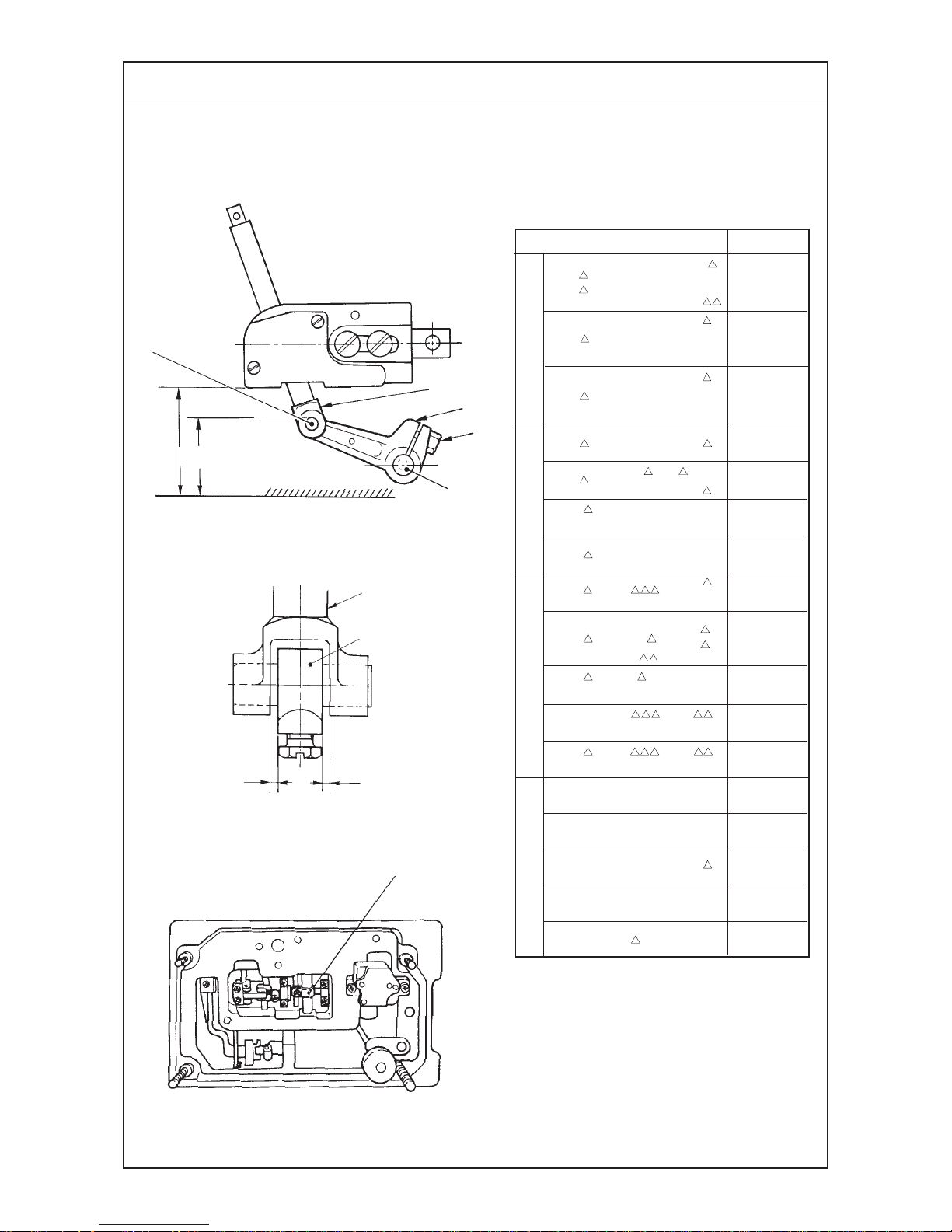
(26) Longitudinal momentum of the top feed dog (Top feed amount)
Longitudinal momentum (top feed amount) of the top feed dog is possible up to 7.5 mm.
Longitudinal momentum (top feed amount)
Max.
7.5mm
7mm
7mm
Standard
MO-6916R-F 6- H
MO-6900J
Min.
1mm
2.5mm
2.7mm
Decreases
Increases
Increases
Decreases
4
2
1
3
5
(Caution) Motion of the top feed is not interlocked with the motion of the bottom feed. The
longitudinal momentum (top feed amount) of the top feed is determined only by
the position of top feed lever 4.
Page 47

−43 −
Adjustment Procedures Results of Improper Adjustment
1) Changing the longitudinal momentum (top feed amount)
of the top feed dog
1 Loosen top feed lock nut 3 and move top feed lever 4 in the
direction of the arrow mark to adjust the stroke.
2 When top feed fine adjustment screw 5 is used, it is possible
to slightly move top feed lever 4.
2) Changing the maximum momentum
1 Loosen setscrew 1 in the differential feed adjustment stopper
and lower the stopper to increase the maximum momentum
and raise the stopper to decrease it.
2 After the adjustment, securely tighten setscrew 1 in the
differential adjustment stopper.
3) Changing the minimum momentum
1 Loosen setscrew 2 in the differential feed adjustment stopper
and lower the stopper to increase the minimum momentum
and raise the stopper to decrease it.
2 After the adjustment, securely tighten setscrew 2 in the
differential adjustment stopper.
™ If the min. stroke is decreased
to 1 mm or less, the components
mounted inside the machine
head may come in contact with
among one another. It is
therefore necessary to set the
min. stroke to 1 mm or more.
™ If the min. stroke is decreased
to 2.5 mm or less for safety
stitch machines of 50H or 60H
type, the top feed dog may
come in contact with the upper
looper holder. It is therefore
necessary to set the min. stroke
to 2.5 mm or more for the
aforementioned types of
machines.
Page 48

−44 −
(27) Vertical momentum of the top feed dog
Standard Adjustment
Relation between the position of vertical adjustment pin
and the vertical momentum
* In case of adjusting the position of vertical
adjustment screw 2, check that the pin does
not come in contact with upper knife support,
needle clamp, etc. Then securely tighten vertical
adjustment screw 2.
Striking to top end of groove
Marker line position A
Marker line position B
1 to 1.5 mm on this side from
striking to top end of groove
(18.7˚)
(24.6˚)
(31.8˚)
(42.5˚)
1
2
Vertical adjustment arm
Assembling position of locus cut base and exhaust slot support
Move exhaust slot support 4
to the right.
(Screw : left side of slot)
Move locus cut base 3 to the left.
(Screw : right side of slot)
0.45mm
3
4
Check that the locus cut screw is adjusted to the position (almost the center) of the aforementioned
dimension of the vertical adjustment arm support section.
Vertical momentum
3.5mm
5.0mm
6.5mm
8.5mm
Adjusting position
Striking to end of groove.
Marker line position A
Marker line position B
1 to 1.5 mm on this side from
striking to end of groove
Application
Light weight material
Light- to medium-weight materials
Medium- to heavy-weight materials
Extra heavy-weight materials
Page 49

−45 −
Adjustment Procedures Results of Improper Adjustment
1) Remove the top cover, locus cut base 3 and exhaust slot
support 4.
2) Loosen vertical adjustment nut 1 and move vertical adjustment
pin 2 to a proper position.
3) After the adjustment, stop locus cut base 3 and exhaust slot
support 4 at the position as shown in the figure.
™ When the position of vertical
adjustment pin 2 is changed,
the vertical momentum of top
feed dog changes.
™ When vertical adjustment pin 2
is moved toward the top end of
vertical adjustment arm, the
momentum is decreased and
when it is moved to the root,
momentum is increased.
™ When the vertical momentum is
increased, jumping occurs and
noise may occur at high speed.
In this case, tighten the upper
Page 50

−46 −
Standard Adjustment
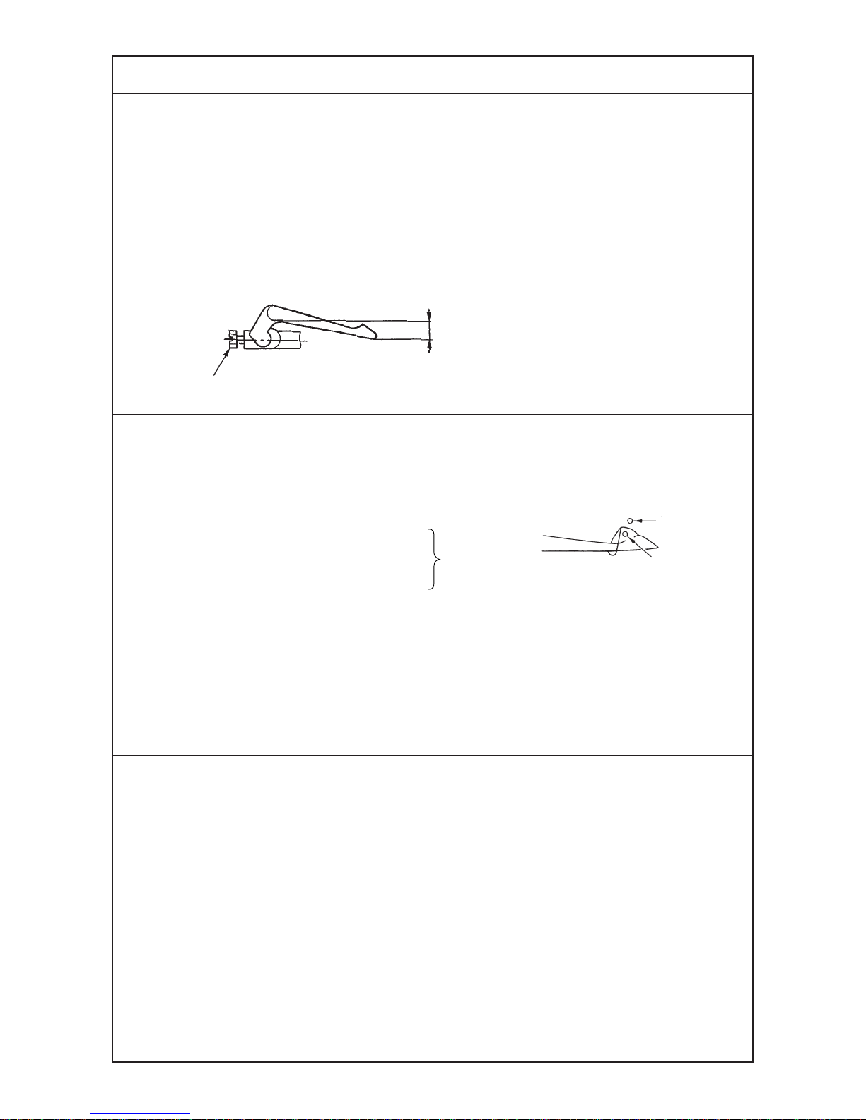
(28) Adjusting the height of the top feed dog
Adjusting the position of lowest point of the top feed dog
It is standard that the top feed dog is 1.0 mm (safety stitch machine : 0.8 mm) from the top surface of
the throat plate when the top feed dog is in the lowest point of its stroke.
It is possible to adjust the position to approximately 1.0 mm above or below the standard adjustment.
(Reference) The standard of the height of the bottom feed dog (main and differential feed dogs)
is 0.8 mm from the top surface of the throat plate and flush with it when the bottom
feed dog is in the highest point of its stroke.
Approx.
1 mm
Approx.
1 mm
Approx.
2 mm
a (Height of top feed dog)
b (Height of bottom
feed dog)
Throat
plate
2
1
™ Adjusting top/bottom feed dogs of various models of the subclasses
0 -30 1.0 0.8
500
50M 1.0 1.0
- 0 1.0 0.8
4
-30 0.8 0.8
-50H 1.0 0.8
-60H 1.5 1.3
1 6 -307 0.8 0.8
0F6 -700 1.5 1.3
CH6 -700 1.4 1.2
FH6 -700 1.3 1.1
Top feed dog height a Bottom feed dog height b
MO-6904R
MO-6914R
MO-6916R
MO-6943R
MO-6904J
MO-6914J
MO-6916J
Model name
(Unit : mm)
Page 51

−47 −
Adjustment Procedures Results of Improper Adjustment
1) Loosen setscrew 1 in the top feed dog and move top feed dog
2 up or down to adjust the height.
(Caution) 1. Perform the adjustment in the state that the
standard top feed pressure is applied.
2. Top feed dog 2 is removed and personal
injuries may occur. Use a rather large-sized
screwdriver and securely fix setscrew 1 in
the top feed dog.
™ When top feed dog is installed
higher than the standard
Sewing of heavy-weight
materials is possible.
However, a clearance is
provided between top and
bottom feed dogs, and partial
shirring performance of lightweight materials or feed force
is decreased.
™ When top feed dog is installed
lower than the standard
Partial shirring performance or
feed force is increased.
However, when overlapping
amount of top and bottom feed
dogs is excessively increased,
feed dog defect is apt to occur.
Besides, sound may become
higher.
™ In case of sewing heavy-weight
materials
It is possible to sew even when
vertical stroke is increased.
Refer to "(27) Vertical
momentum of the top feed dog".
Page 52

−48 −
Standard Adjustment
(29) Locus cut of the top feed dog
Locus cut mechanism makes longer the section where the feed
dog actually feeds cloth by leveling the lower side of the locus of
top feed dog motion.
By this mechanism, the effect of prevention of irregular stitches
can be obtained when sewing materials thicker than mediumweight ones such as knitted fabrics or the like although the effect
is less for light-weight materials.
The locus cut mechanism does not work in the state of delivery.
1
2
Set the standard of cut amount to approximately 0.5 mm.
Locus of feed dog
Cloth
Range of
effective feed
Range of
effective feed
Cut amount
(30) Adjusting the longitudinal position of the top feed dog
Clearance between top feed dog 2 and the groove of presser 3, when
top feed stroke0 is maximum, is as shown in the list below.
Clearance between top feed dog 2 and groove of presser 3 when top
feed dog 2 travels to the front end = dimension A
2
3
A
Thrust collar
1
Top feed arm C
Model name dimension A
MO -6916R-F
6 -50H 0.8
F 6 60H
MO -6943R -1D6 -307 1.0
All models of MO-6900R, and J 0.5
excluding aforementioned models
(Unit : mm)
Page 53

−49 −
Adjustment Procedures Results of Improper Adjustment
1) Remove the top cover.
2) Turn the handwheel to bring the top feed dog to the lowest
point of its stroke.
3) Loosen locus cut screw nut 1 and tighten locus cut screw 2.
Then the top feed dog rises.
4) When a proper cut amount is obtained, tighten locus cut screw
nut 1 so that locus cut screw 2 does not turn.
5) Loosen the setscrew in the top feed dog and lower the top feed
dog to the position where it bites cloth.
(Caution) 1. When using the machine with locus cut, use
the machine at a speed of 5,500 rpm or less.
2. When the cut amount exceeds 1 mm or more,
a forced load is applied to the mechanism.
Use the machine with locus cut of less than
1 mm.
™ The lifted amount from the
lowest point in the step 3) is the
cut amount. In this state, the
clearance between top and
bottom teeth is increased as
large as the cut portion and feed
force is decreased. Be sure to
adjust the biting amount of cloth
by lowering the top feed dog in
the step 5).
1) Remove the top cover and loosen clamping screw 1 in the top
feed arm C to adjust the position.
2) The tightening torqueses of clamping screw 1 in the top feed
arm C after the adjustment is 80N.
(Caution) 1. Do not completely loosen clamping screw
1 in the top feed arm C.
2. If clamping screw 1 in the top feed arm C is
loosened and has moved to the right or left,
completely loosen it, turn the handwheel
and tighten it at the position where it comes
naturally.
™ When dimension A is improper,
top feed dog 2 comes in contact
with presser 3, and noise
occurs.
Besides, the dimension is
excessively improper, the top
feed dog may come in contact
with other components in the
frame. Be careful when
performing the adjustment.
Page 54

−50 −
Standard Adjustment
(31) Adjusting the lateral position of the top feed dog
Clearance between top feed dog 4 and presser 3 is 0.2 mm.
a = a’ (0.2 mm)
b = b’ (0.2 mm)
(Caution) 1. Adjust the position only when there is a concrete problem that presser 3 and top
feed dog 4 come in contact with each other and noise occurs, the left and right
clearances are excessively different from each other and trouble occurs, etc.
2. When the adjustment value is improper, there is the possibility that contact among
the components occurs, a bad influence is given to the durability of the sewing
machine or the like since the top feed mechanism is strictly assembled because
of the space. So, be careful.
4
3
a
a’
b
b’
2
1
Top feed arm C
Page 55

−51 −
Adjustment Procedures Results of Improper Adjustment
1) Loosen the setscrew in the feed bar guide B.
Refer to “(33) Adjusting the feed bar guides A and B”.
2) Remove the top cover and loosen setscrew 1 in the top feed
arm C.
Refer to (30) Adjusting the longitudinal position of the top feed
dog.
3) Loosen the setscrews in thrust collars 2 located on the both
sides of the horizontal shaft and move the set of horizontal
shaft, top feed bar and top feed dog to the predetermined
position in the thrust direction (direction you desire to adjust
the position). Then fix two thrust collars 2 at the position.
(Reference) When loosening the setscrews in thrust collars
2, do not simultaneously loosen the two setscrews. First,
loosen thrust collar 2 on the side of moving direction and
fix it at the predetermined position. In the state of pressing
it in the direction, check that contact at the lateral position
or at the top feed mechanism does not occur. After the
checking, move and fix the remaining thrust collar 2. The
aforementioned procedure can perform good adjustment.
4) Tighten the respective setscrews by reversing the
aforementioned order and perform the adjustment.
™ Excessive move in both
directions of cloth base side and
handwheel side produces the
contact of top feed bar with the
respective sections of top feed
mechanism.
(Fully check the change of
torque, engagement, or noise at
the time of adjustment.)
Page 56

−52 −
Standard Adjustment
(32) Position of the motion of the top feed dog
Adjusting the position of the motion of the top feed dog
Loosen the setscrew in horizontal arm A 1 and move the position of horizontal arm A 1 to change
the position of the motion of the top feed dog.
™ Intermediate constant
When the pitch of the top feed dog is increased, the top feed dog extends to the front and rear.
™ Rear constant
When the pitch of the top feed dog is increased, locus extends to the front while the most retarded
position of the top feed dog is constant.
™ Front constant
When the pitch of the top feed dog is increased, locus extends to the rear while the most advanced
position of the top feed dog is constant.
Position of the motion
of the top feed dog
changes by changing
the installing angle
of ˚ horizontal
arm A 1 and horizontal
arm B 2.
Intermediate constant (standard) Rear constant Front constant
˚
2
1
4
3
Horizontal feed link 4
should not sway to the right or left.
Page 57

−53 −
Adjustment Procedures Results of Improper Adjustment
™Intermediate constant
1) Make horizontal arm A 1 in the state of temporary tightening,
turn the handwheel and adjust the top feed dog to the position
where it is desired to be constant.
2) At the position, tighten horizontal arm A 1 at the position where
the top feed dog does not move even when the top feed lever
is moved.
3) Loosen horizontal arm C 3 at the position where the top feed
dog does not come in contact with the front or rear of the groove
of the presser even when the pitch of the top feed dog is
maximized. Then adjust the position of the horizontal shaft.
™ Rear constant
1) Make horizontal arm A 1 in the state of temporary tightening,
turn the handwheel and adjust the top feed dog to the most
retarded position.
2) At the position, tighten horizontal arm A 1 at the position where
the top feed dog does not move even when the top feed lever
is moved.
3) Loosen horizontal arm C 3 at the position where the top feed
dog does not come in contact with the front or rear of the groove
of the presser even when the pitch of the top feed dog is
maximized. Then adjust the position of the horizontal shaft.
™ Front constant
1) Make horizontal arm A 1 in the state of temporary tightening,
turn the handwheel and adjust the top feed dog to the most
advanced position.
2) At the position, tighten horizontal arm A 1 at the position where
the top feed dog does not move even when the top feed lever
is moved.
3) Loosen horizontal arm C 3 at the position where the top feed
dog does not come in contact with the front or rear of the groove
of the presser even when the pitch of the top feed dog is
maximized. Then adjust the position of the horizontal shaft.
(Caution) 1. Never loosen horizontal arm B 2 since it
keeps the thrust of the horizontal drive shaft.
2. Set horizontal arm C3 to the position where
horizontal feed link 4 lightly moves without
play.
3. Provide a clearance of 0.5 mm or more
between the top feed dog and the groove of
the presser when the pitch is maximized.
™ At the time of rear constant, the
lowest point of the top feed dog
is apt to be lowered when
increasing the top feed stroke
(clearance between top feed
and bottom feed dogs is
increased) and there is no effect
for partial shirring. Use the top
feed dog with intermediate
constant or front constant.
™ When the top feed dog is set to
front constant, biting of cloth at
the start of sewing is improved.
However, a few loading is apt to
occur at the overlapped section
of knit fabric
™ If the play between horizontal
arm C 3 and horizontal feed link
4 is large, the return of the top
feed adjusting lever is worsened
and a forcible load is applied to
the components.
Page 58

−54 −
Standard Adjustment
(32) Position of the motion of the top feed dog
1. The position of motion is adjusted to rear constant for 50H and 60H series and MO-6900J, and to
intermediate constant for other models at the time of delivery so that the best locus suitable to the
purpose of use can be obtained.
2. Intermediate constant position at the time of delivery
The position of motion of the top feed dog other than that of 50H, 60H and MO-6900J is adjusted
to the position where the top feed dog does not move even when the top feed lever is moved at the
position where the timing is advanced by 19˚ from the upper dead point of needle.
(33) Adjusting the feed bar guides A and B
When the play of the top feed dog in the lateral direction is excessively increased, the play can be
removed by adjusting the feed bar guides A and B.
1
2
3
4
5
6
78
19˚
Upper dead point of needle
Upper dead point
of needle
19˚
2˚
Approx. 10 mm
Hole on this side
Oil pan side
Page 59

−55 −
Adjustment Procedures Results of Improper Adjustment
™ Standard of the position where timing is advanced by 19˚from
the upper dead point of the needle
1) Timing is advanced by approximately 21˚ from the upper dead
point of the needle at the position where the hole in the periphery
of the handwheen faces just under.
1) Remove top cover, locus cut base, exhaust slot support, and
adjusting arm spring.
2) Loosen top presser adjusting screw 1, top presser adjusting
screw nut 8, release top presser pressure, and check the play
in the lateral direction of top feed dog 2.
3) Remove the needle thread tank, loosen setscrew 3 in the feed
bar guide B and temporarily tighten feed bar guide B 4 so that
top feed bar 6 is put between feed bar guides B 4 and A 5.
4) Move top feed dog 2 up or down and adjust so that top feed
dog 2 comes down by its weight and that the play in the lateral
direction of top feed dog 2 is kept down to a minimum.
5) When jar is produced at top feed dog 2 and the top feed dog
does not come down by its weight even after adjusting feed
bar guide B 4, loosen setscrew 7 in the feed bar guide A and
adjust feed bar guide A 5 at the same time. At this time, adjust
the lateral position of top feed bar 6 to the position where top
feed dog 2 drops naturally when moving it up or down several
times.
6) Securely tighten the respective setscrews and check that there
is neither play nor jar.
7) Return adjusting arm spring, exhaust slot support, locus cut
base and top cover to their home places.
Refer to “(27) Vertical stroke of the top feed dog”.
(Caution) When jar occurs between feed bar guide A 5 and B 4,
and top feed bar 6, jumping of top feed dog 2 will be caused.
Adjust the top feed dog to such an extent that it comes
down by its weight as mentioned above.
™ When the play in the lateral
direction of top feed dog 2
occurs, the top feed dog comes
in contact with the presser and
noise occurs or feed dog defect
is apt to be put on cloth.
™ On the contrary, when torque
occurs between fedd bar guides
A 5 and B 4, and top feed bar
6, inducement of the jumping
phenomenon of top feed dog 2
will be caused.
Page 60

−56 −
Standard Adjustment
(34) Adjusting the top feed dog pressure
<Standard height of top presser adjusting screw>
MO-6900R
MO-6900J
Dimension A
24 to 25mm
20.5 to 21.5mm
20.5 to 21.5mm
Vertical amount of
top feed dog
Less than 6.5mm
6.5 to 8.5mm
8.5mm
Max.
sewing speed
7,000rpm
7,000rpm
6,000rpm
1. Standard is the position where the top feed dog stops jumping and, when further the screw is
tightened, sound becomes quiet and is stabilized when gradually tightening the screw from the
lower pressure.
Besides, when using the top feed dog making low the top feed dog pressure, decrease the vertical
amount of the top feed dog or decrease the sewing speed.
2. Dimensions listed in the list are slightly increased values that can be guaranteed even when the
vertical amount of top feed dog and sewing speed are in the most strict combination in the list.
Accordingly, when using the machine by decreasing the vertical amount of the top feed dog or
decreasing the sewing speed, use it with rather large value (top feed dog pressure is low) than
dimensions A in the list.
2
1
A
(35) Lifting amount of the top feed dog (when operating the pedal)
The height of the top feed dog from the top surface of the throat plate when the pedal is depressed at
the lowest point of the needle bar and the top feed dog goes up to the highest point is 9 ± 0.5 mm.
In case of MO-6900J, the height is 10.5 ± 0.5 mm.
1
3
2
Top feed dog
Throat plate
9 ± 0.5mm
Page 61

−57 −
Adjustment Procedures Results of Improper Adjustment
Loosen top presser adjusting screw nut 1, when tightening top
presser adjusting screw 2, the top feed dog pressure is increased
and feed force is increased. After the adjustment, be sure to tighten
top presser adjusting screw nut 1.
(Caution) When the top feed dog jumps and noise becomes
large during using the sewing machine, tighten top presser
adjusting screw 2 until noise becomes small. When the
machine is used for many hours while noise is excessively
large, a forcible load is applied to other section. So, be
careful.
1) Loosen lifter B stopper nut 1 and turn lifter B stopper screw 2
to adjust the lifting amount.
2) After the adjustment, tighten lifter B stopper nut 1.
<Checking after adjustment>
Play between the top end of lifter B stopper screw 2 and
presser lifting arm 3 should be 0.5 to 1 mm when the top
feed dog is brought to the lowest point (needle bar is at highest
point).
(Top end of the screw should be separated from presser lifting
arm 3 by 0.5 to 1 mm when pulling the lifter B with finger.)
™ When top feed dog pressure is
excessively low
Top feed dog jumps and noise
becomes large.
Feed force is decreased.
™ When top feed dog pressure is
excessively high
Feed dog defect is put on some
materials.
Unnecessary load is applied to
the sewing machine and the
sewing machine is influenced for
the worse by it.
Noise level is increased.
™ When the lifting amount of the
top feed dog is excessively high,
contact occurs between vertical
shaft and lifter B, and noise
occurs when operating the
sewing machine.
™ When the lifting amount of the
top feed dog is excessively low,
when entering cloth at the start
of sewing heavy-weight
materials, cloth may be not able
to be entered at the top feed
dog.
Page 62

−58 −
Standard Adjustment
(36) Height of the presser (pedal operation)
Height of the presser from the top surface of the throat plate when the presser goes uo to the highest point
(Caution) When height A of the presser is adjusted at the time of operating the pedal, in
connection with it, the adjustment value of the lifting amount of the top feed dog is
changed. Check the lifting amount of the top feed dog after adjusting the height of
the presser referring to “(35) Lifting amount of the top feed dog (when operating the
pedal)”
Height
of presser A (Max.)
7
6.5
5.5 ± 0.2
5.5 ± 0.2
5.5 ± 0.2
5 ± 0.2
5 ± 0.2
7
6.5
6.5
8
Model
MO -6904R -0 4 -300
0 6 -300
0 4 -500
MO -6914R -B 4 -307
B 6 -307
MO -6916R -D 4 -300
D 6 -300
FF6 -300
F 6 -50H
F 6 -60H
MO -6943R -1D6 -307
MO -6914R -B 6 -337
MO -6914R - -4 H
Whole MO-6900J
0
0
–1
0
–1
0
–1
0
–1
0
–1
A
Throat plate
1
2
3
4
5
6
7
8
9
A
3
6
Level
Presser
(Unit : mm)
–1
Page 63

−59 −
Adjustment Procedures Results of Improper Adjustment
1) In the state that the presser pressure is applied, loosen presser
turning lock nut 5 and adjust the height with presser lifter turning
setscrew 4 so that the height in the list is obtained when
operating the presser lifting pedal.
At this time, check that there is no contact of the presser with
upper looper, needle clamp, top feed dog, etc.
(Caution) Adjust the height so that there is a slight clearance
between presser arm 8 and presser arm stopper 9 when
pedal is pressed and presser lifting arm 3 comes in contact
with presser lifter turning setscrew 4 and stops.
™ Adjust the height by the procedure below even when presser
thrust arm 6 is removed.
1) Removing the thrust play of the presser shaft, temporarily
tighten thrust arm clamping screw 7.
Lower the presser by 1 to 3 mm from the throat plate with
presser arm 8.
2) Next, in the state of the aforementioned 1), fix presser lifter
arm 3 with thrust arm clamping screw 7 so that presser lifter
arm 3 is level and there is no clearance at section A.
3) Adjust the lifting amount of the top feed dog with the
aforementioned lifter B stopper screw 2 and nut 1, and adjust
the height of the presser with presser lifter turning setscrew 4
and nut 5 so that the height in the list is obtained.
™ When the height of the presser
is excessively low, entering or
taking out of cloth becomes
hard.
™ When the height of the presser
is excessively high, there is the
possibility that the presser
comes in contact with upper
looper, needle clamp, etc.
Page 64

−60 −
Standard Adjustment
(37) Lifting amount of the top feed dog (when the presser lifting lever is operated)
It is the standard that the height from the top surface of the throat plate is 9 ± 0.5 mm when presser
lifting lever 5 is pressed at the lowest point of the needle bar and top feed dog 7 goes up to the
highest point. MO-6900J : 10.5 ± 0.5 mm
Throat plate
9 ± 0.5mm
7
1
2
3
4
5
6
7
Page 65

−61 −
Adjustment Procedures Results of Improper Adjustment
1) Remove cloth base side cover 2 and top feed cover 1.
2) Bring the needle bar to the lowest point of its stroke and keep
top feed dog 7 at the height of 9 ± 0.5 mm (MO-6900J : 10.5 ±
0.5 mm) from the top surface of the throat plate.
(Insert the spacer between the throat plate and top feed dog 7.)
3) Loosen clamping screw 4 of lifter A 3.
4) Press presser lifting lever 5 until it will go no further and turn
it. In this state, turn lifter A 3 and strike the pin section to the
eaves section of top feed square block 6. Then tighten
clamping screw 4 of lifter A 3.
(Caution) In the state that presser lifting lever 5 is returned,
check that there is a clearance between the pin of lifter A
3 and the eaves section of top feed square block 6.
5) Return top feed cover 1 and cloth base side cover 2 to their
home positions.
™ When the lifting amount of top
feed dog 7 is excessively high,
contact of top feed square block
6 with the pin section of liter A
3 occurs at the time of
operation and something is
wrong with the machine.
™ When the lifting amount of top
feed dog 7 is excessively low,
cloth or the presser becomes
hard to be removed at the thick
section such as overlapped
section or the like.
Page 66

−62 −
Standard Adjustment
(38) Position of the thread guides and the looper thread take-ups
A
B
Needle thread
take-up
Needle
thread guide
The thread hole in the needle thread guide
and the hooked portion of the needle thread
take-up are in the position where 2/3 of the
hole in the needle thread guide can be
observed.
A
B
Needle thread take-up lever of
2-needle machine
Needle thread guide
of 2-needle machine
The thread hole in the needle thread guide
and the hooked portion of the needle thread
take-up are in the position where 2/3 of the
hole in the needle thread guide can be
observed.
A
B
C
D
P
Needle thread
guide
Needle thread
take-up lever of
doublechainstitch
machine
Needle thread takeup guide of double-
chainstitch machine
The thread hole in the needle thread guide
and the hooked portion of the needle thread
take-up are in the position where 2/3 of the
hole in the needle thread guide can be
observed.
The thread hole in the double-chainstitch
needle thread guide and the hooked
portion of the needle thread take-up are
in the position where the entire hole in
the needle thread guide can be observed.
MO-6
04S (R) MO-6 14S (R) MO-6 16S (R)
(Caution) The needle thread take-up shall be positioned at the lower dead point.
Upper looper thread
guide (middle)
Upper looper thread guide (upper)
Upper looper thread guide (right)
Lower looper
thread guide
Lower looper thread take-up
Looper thread
take-up (rigjt)
Looper thread
take-up (left)
E
G
K
L
N
M
I
J
H
F
MO-6
04S (R) MO-6 14S (R) MO-6 16S (R) MO-6 16S (R) MO-6 05S (R) MO-6 04S (R)
(Standard) (Standard) (Standard) (50H, 60H) (Hemming) (Soft chain)
Symbol
General
thread
Woolly
thread
General
thread
Woolly
thread
General
thread
Woolly
thread
General thread Woolly
thread
General thread
A 15.8 ,, ,, , , ,, 13.5
B
3.4 ,, ,1.8 , 2.6 3.4 , 2.1
C
- - - - 21.5 , 2.3 - - -
D
- - - - 30.5 , 24.5 - - -
E
22 ,, ,, , , ,, ,
F65,, ,, , , ,, ,
G 17.5 ,, ,, , , ,, ,
H 43.5 ,, ,, , , 40.5 , 43.5
I 26.5 ,, ,, , , 24 , 26.5
J384138, 34 36 34 38 42 43.5
K15, 12 15 12 15 12 12 , 14
L 6.5 , 10 , 6.5 ,, 24 34 ,
M29,, ,27.5 ,, 29 , 26.5
N272123, 20 , 19 24 , 19
O11,, ,, , , 12 , 9.5
P----16, 12.8 - - -
(Unit : mm)
General
thread
Page 67

−63 −
1) Perform the adjustment by the setscrews. Position of the needle
thread guide 1 and needle thread take up 2 lever is a very
important decisive factor when making soft chains since the
needle thread take-up amount is increased in this case. So,
carefully position these parts.
2) Set distance I a little smaller when
using synthetic thread or the like
which tends to form stitches swelling
out of the cloth edge.
A smaller I is effective for preventing
stitch skipping.
3) Distance J is related to the vertical knotting point of the upper
and lower looper threads.
Set this distance larger for wooly thread, and set it smaller for
thin thread which is likely to cause stitch skipping.
4) It is desirable to set distance K larger for stretchy threads such
as wooly thread.
5) Set distance L a little larger when making blind hemming soft
chain stitches.
6) Set distance N a little smaller for blind hemming or making soft
chain stitches.
7) Set distance O larger if stitch skipping occurs due to looper
thread slack.
Set it smaller for better appearance and touch of produced
stitches when wooly thread is used.
Adjustment Procedures Results of Improper Adjustment
™ Distance a
When set smaller, better
tightness of needle thread
stitches will be obtained.
When set larger, loose needle
thread stitches will result.
™ Distance E, F and H exert least
influence on stitch formation,
however, improper setting of
these distances will cause
contact between the moving
parts.
™ Distance J
When set larger, the amount of
the upper looper thread will be
increased.
When set smaller, the amount
of the upper looper thread will
be decreased.
™ Distance K
When set larger, the amount of
the upper looper thread will be
increased.
When set smaller, the amount
of the upper looper thread will
be decreased.
™ Distance L
When set larger, the amount of
the upper looper thread will be
increased.
When set smaller, the amount
of the upper looper thread will
be decreased.
™ Distance N
When set larger, the amount of
the upper looper thread will be
increased.
When set smaller, the amount
of the upper looper thread will
be decreased.
™ Distance I
When set larger, the amount of
the upper and lower looper
threads will be increased.
When set smaller, the amount
of the upper and lower looper
threads will be decreased.
™ Distance O
When set larger, the amount of
the upper and lower looper
threads will be decreased.
When set smaller, the amount
of the upper and lower looper
threads will be increased.
Needle
a
Needle thread
take-up amount
Swell out
Lower looper
Thread slack
Upper looper
Thread slack
Upper looper
Small
Large
1
2
Page 68

−64 −
Standard Adjustment
(39) Adjusting soft chain making mechanism
1) Replacing the parts with those exclusively designed for making soft chains
1 Needle thread presser plate C.......12112504
2 Driving cam....................................12112603
3 Needle thread presser spring B.....12112702
4 Throat plate....................................(only for 1-needle
overlock machine)
0D4-300 .........................................R4200J6DD0A
2) Adjustment value
1 Needle thread guide and needle thread take-up lever
Adjust the needle thread guide to increase the needle thread feeding amount when the needle bar
is in the lowest dead point of its stroke.
2 Adjust the rising amount of needle thread presser plate C.
Adjust the rising amount of needle thread presser plate C 1 to 0.6 to 1 mm (max.) by moving
driving cam 2 to the right and left within the slot.
Rising amount : 0.6 to 1 mm (max.)
Cam face
(16 Safely stitch machine)
Cam face
1
2
3
Max. slot of the needle
thread guide
Needle thread takeup amount when the
needle bar is in its
lowest dead point
3.1 to 3.6mm
(04 1-needle overlock machine)
Max. slot of the needle
thread guide
Needle thread takeup amount when the
needle bar is in its
lowest dead point
2.5 to 3mm
1
2
Rising amount
2
Page 69

−65 −
3) Important points in adjustment
1 Increase the thread take-up amount of the needle thread take-up lever.
Refer to the adjustment values related to the needle thread guide and needle thread take-up lever.
2 Reduce the feed of the looper threads. (Mainly lower looper thread)
Set J, K, L and M for the soft chain distances.
Fine adjustment of J and M is required to produce even stitches.
3 Adjsut the thread tension while checking the appearance and touch of the stitches produced.
1) Minimize the needle thread tension as far as satisfactory tightness of needle thread stitches is
obtained.
2) Increase the upper looper thread tension as much as possible.
4 If the chain-off thread does not stretch satisfactorily, and if it is not satisfied, proceed with the
following.
1) Increase the upper looper thread tension.
2) Further increase distances J and K.
3) Further increase the upper looper thread tension.
4) Increase the lower looper thread tension to a maximum as far as good tightness of needle
thread stitches is maintained.
5) Increase the thread take-up amount. If the needle thread is poorly tensed, increase the needle
thread tension.
5 Fine adjustment for producing stitches with better appearance and touch
1) If the knotting point varies at high or low sewing speed, slightly reduce L, and increase the
lower looper thread tension.
2) If a knot is made at a high point, increase J and I.
3) If the needle thread is likely to break, decrease the thread take-up amount and lower the needle
thread tension.
6 Pay attention to the following
1) Minimize the needle thread tension as far as satisfactory tightness of needle thread stitches is
obtained.
2) The knot of upper and lower looper threads should be made near the upper edge of a material.
3) Minimize the lower looper thread tension as far as even stitches are maintained.
4) For a safety stitch machine, adjust the soft chain making mechanism so that uniform chain-off
thread is produced during double-chain stitching and overlocking.
The value given in ( ) parentheses
is the adjustment value for the
safety stitch machine. (Unit : mm)
Upper looper thread
guide (middle)
Upper looper thread guide (upper)
Upper looper thread guide (right)
Lower looper
thread guide
Lower looper thread take-up
Looper thread
take-up (rigjt)
Looper thread
take-up (left)
E
22
G
17.5
K
14
O
9.5
Soft chain stitches
Standard stitches
Looper thread should not be
loosened and stretch well
The looper thread loosens
e
e
When the chain-off
thread is pulled.
When the chain-off
thread is pulled.
L
33.5 (27)
N
19
M
26.5
I
26.5 (24)
J
43.5(36.5)
H
43.5
F
65
Page 70

−66 −
Standard Adjustment
(40) Position of the thread guides and the looper thread take-ups of MO-6900G(J)
(Caution) The needle thread take-up shall be positioned at the lower dead point.
MO-6904G (J) MO-6914G (J) MO-6916G (J)
MO-6903G MO-6905G
Frame
Needle thread
guide
4mm
The thread hole in the needle thread
guide and the hooked portion of the
needle thread take-up are in the
position where 1/2 to the entire hole
in the needle thread guide cannot be
observed.
Frame
Needle thread
guide
Needle
thread
take-up
Approx. 2 mm
14.8mm
Needle thread take-up of
2-needle machine
Frame
Needle thread
guide of 2-needle
machine
The thread hole in the needle
thread guide and the hooked
portion of the needle thread takeup are in the position where 1/2 to
the entire hole in the needle thread
guide cannot be observed.
Frame
Needle thread
guide
Needle
thread
take-up
10mm
2.5mm
Frame
Needle thread take-up of doublechainstitch machine
The thread hole in the needle
thread guide and the hooked
portion of the needle thread takeup are in the position where 1/2 to
the entire hole in the needle thread
guide cannot be observed.
16.5mm
15mm
3mm
1.8mm
15.8mm
Needle thread
guide
Needle thread
take-up
33mm
26mm
36mm
2.5mm
2mm
Page 71

−67 −
B
D
J
K
I
H
F
E
C
A
G
B
D
J
K
I
H
F
E
C
A
G
D
K
H
C
G
MO-6904G (J), 6914G (J), 6916G (J)
MO-6905G
MO-6903G
(Unit : mm)
(Caution) The upper looper thread-take-up (right)
and the looper thread take-up (left) shall
be positioned at the extreme right point
of the upper looper.
Position MO-6904G(J)-0F6-700 MO-6914G(J)-CH6-700 MO-6916G(J)-F 6-700 MO-6905G-0M6-7 0 MO-6903G-0N6-3D1
A70 ,,65 B22 ,,20 C48 ,,46 52
D18 ,,,,
E43 ,,22 F22 ,,18 G11 ,,16 13
H27 ,,26 31
I23 ,,20 J18 ,,10 -
K17 ,,,27
Page 72

−68 −
4. ADDITIONAL INFORMATION AND PRECAUTIONS
(1) Thread tension
1) Strength of tension spring
Part No.
11550100
11550209
13137807
13138508
13138805
B3121804000
Color
Purple
Green
Red
Yellow
Blue
Gray
Natural length
(mm)
19.5 mm
19.5 mm
19.5 mm
17.8 mm
17.3 mm
13.8 mm
Operating
length (mm)
11.5 mm
11.5 mm
11.5 mm
9.8 mm
9.3 mm
5.8 mm
Weight required to compress
spring to working length
8.92±0.49N (910 ± 50 g)
6.27±0.49N (640 ± 50 g)
4.21±0.49N (430 ± 50 g)
3.14±0.34N (320 ± 35 g)
1.47±0.20N (150 ± 20 g)
1.47±0.20N (150 ± 20 g)
Where to use
Model
Needle thread Double-chainstitch
needle thread
Upper looper
thread
Lower looper
thread
MO-6 04S(R) series Red – Yellow Blue
MO-6 05S series Yellow – Blue Yellow
MO-6 12S series Red Yellow – Yellow Blue
MO-6 14S(R) series Red Yellow – Blue Yellow
MO-6 16S(R)- - (4 or lower) Red Yellow Yellow Blue
MO-6 16S(R)- -50 Red Red Blue Yellow
MO-6 16S(R)- -60H Green Green Blue Yellow
MO-6 43S(R) series Red Red Yellow Blue Yellow
MO-6 45S series – Red Red – –
MO-6903G-0N6-3D1 Blue – – Blue
MO-6904G(J)-0F6-700 Purple – Yellow Red
MO-6905G-0M6-7 0 Yellow – Yellow Purple
MO-6914G(J)-CH6-700 Red Yellow Yellow Red
MO-6916G(J)-F 6-700 Purple Green Yellow Red
Nos.engraved on
upper looper
*1188 81
1199 92
1217 62
*1217 60
120148
123835
123837
123836
123835
Model
6 04S(R) series
6 16S(R) series
6 14S(R) series
6903G-0N6-3D1
6904G(J)-0F6-700
6905G-0M6-7 0
6914G(J)-CH6-700
6916G(J)-F 6-700
Needle No.
(kind)
#9 #11 #14
#14 #16 #18
#21
#16 (DOx5)
#21 (DOx5)
#24 (DCx1)
#18 (DOx5)
#21 (DOx5)
(2) Upper looper
Use a proper upper looper in accordance with the needle No. When ordering, refer to the Parts List. The
numbers shown in frame in the table below are engraved markers. In addition, the letters in ( )
parentheses are the kinds of the needles.
Parts Nos. with an asterisk * are factory-installed on the standard machine heads at the time of delivery.
2) Springs used for each model.
Page 73

−69 −
(3) Center-to-center distance of the upper looper holder
The center-to-center distance of upper looper holder 1.
(Caution) * (asterisk) marks are exclusive for
to the MO-6900G(J). They are not
common to the MO-6000S(R) series.
(4) Caution in assembly
1) Application of sealant
1 Setscrew of the throat plate base (B) retainer 2 (JUKI seal)
Apply the sealant only to the right setscrew.
2 Bottom surface of the upper looper guide support 3 (Three-bond 1104)
Apply the sealant to the bottom surface of the upper looper guide support 3, which contacts with the
frame surface.
3 After assembling the front edge of the upper looper guide support 3 (Three-bond 1212), apply the
sealant to the gap of the contact surface between the frame and the upper looper guide support 3
( section in the illustration).
Model
MO- 6 04S(R) - -
6 05S - - 0
MO- 6 04S(R) -
0D4 to 0E4
4 H
0F6 50H
MO- 6 12S -CE4 -40H
MO- 6 12S -D MO- 6 14S(R) - MO- 6 16S(R) - - 0
BE4
DD to FF
MO- 6943R - - 7
MO- 6 43S - -40H
MO- 6903G -0N6 -3D1
MO- 6904G(J) -0F6 -700
700
7E0
MO- 6914G(J) -CH6 -700
FH6
FF6
Center-to-center distance H
38
39
38
39
39
38
39
39
39
*39
37.5
*39
37.5
37.5
MO- 6 16S(R)- -
MO- 6916G(J) - -700
Apply only to
the right
setscrew
Apply the sealant to the
bottom surface.
234567
8
234567
8
Frame
Be careful not to allow the
sealant to run to the rear.
Apply the sealant to
bottom surface.
(Unit : mm)
1
H
2
3
-
MO- 6905G -0M6 -
4 H
5 H
Page 74

−70 −
4 Portion of the setscrews of the dust-proof rubber case (JUKI seal)
Apply the sealant to the oil shield case setscrew 1 (1 pc.) and the dust-proof rubber case 2 setscrews
(4 pcs.)
5 Oil shield plate assembly (JUKI seal)
Apply the sealant to the inside of the oil shield plate 3.
6 Portion of the feed mechanism cover (Three-bond 1212)
Apply the sealant to the rear face of the feed mechanism cover, the top surface of the oil shield plate,
the oil shield rubber support plate , the top surface of the oil shield case, and the hatched parts on the
top surface of the feed bar presser.
Apply the sealant to
the hatched parts.
Lightly apply the sealant to the rear
face of the feed mechanism cover
and the top surface of the feed bar
presser.
Apply the sealant to the
top surface of the oil
shield plate.
Apply the sealant to the frame.
Apply the sealant to the oil shield rubber support
plate and the top surface of the oil shield case.
Be careful that the sealant should not overflow on
the side of the oil shield rubber.
Feed mechanism
cover (rear face)
Inside contact surface
1
2
3
Page 75

−71 −
2) Precautions to be taken with respect to the lubricating components
Feed bar components
™ Be careful of the orientation of the oil shield rubber 4 and the dust-proof rubber 5.
™ Assemble the feed bar presser 6 and the dust-proof rubber case 2 so that their top faces are flush
with the frame plane on which the feed mechanism cover is installed.
™ Do not loosen the screws in feed bar presser 6 unless it is necessary. The clearance between the feed
bar presser and the feed bar and the contact with each other are important.
* Assembling as shown in the illustration will
result in oil leakage. So, be careful.
Do not loosen the screws.
e
2
4
5
6
7 Various sealants
JUKI exclusive part Nos. of the above 3 kinds of the sealants are not set.
Maker’s name Part No.
Three Bond 1104D *
Three Bond 1104
Three Bond 1212
* : It is commonly called “JUKI seal”.
Page 76

−72 −
* Use a motor of 3/4 HP (550 W) when the sewing machine runs at 7,000 rpm or higher speed.
Use a motor of 1/2 HP (400 W) when the sewing machine runs at a speed lower than 7,000 rpm.
(Caution) If a motor of less than 400W is used, in the low tenperature area, viscosity of oil increases
and the sewing speed may not increase or the sewing machine may fail to run in some
cases.
* Part No. of motor pulley
MTKP0xxx000 (Enter the effective diameter to “xxx.”)
If the outside diameter of the motor pulley is 150 mm, the effective pulley will be 145.
.....So, the part No. will be MTKP0145000.
If the outside diameter of the motor pulley is 90 mm, the effective pulley will be 085.
.....So, the part No. will be MTKP0085000.
* Part No. of belt
MTJVM00xx00 (Enter a number that shows the belt length to “xx.”)
If the belt length is 1016 mm (40 inches), enter “40” to “xx.”
.....So, the part No. will be MTJVM004000.
If the belt length is 889 mm (35 inches), enter “35” to “xx.”
.....So, the part No. will be MTJVM003500.
(5) Kinds of motor pulleys, belts and frame support plate bolts
1) Motor pulleys and belts
MO-6 00S(R)
MO-6900G(J)
Sewing speed of
sewing machine
(rpm)
8500
8000
7500
7000
6500
6000
5500
5000
4500
4000
50 Hz
160 (155)
150 (145)
140 (135)
130 (125)
120 (115)
110 (105)
100 (95)
90 (85)
85 (80)
75 (70)
Semi-sunken
type mm (inch)
1016 (40)
1016 (40)
965 (38)
965 (38)
965 (38)
914 (36)
914 (36)
889 (35)
889 (35)
864 (34)
Fully-sunken
type mm (inch)
914 (36)
864 (34)
864 (34)
864 (34)
813 (32)
813 (32)
813 (32)
762 (30)
762 (30)
762 (30)
60 Hz
135 (130)
125 (120)
120 (115)
110 (105)
100 (95)
95 (90)
85 (80)
80 (75)
70 (65)
60 (55)
Semi-sunken
type mm (inch)
965 (38)
965 (38)
965 (38)
914 (36)
914 (36)
889 (35)
889 (35)
864 (34)
864 (34)
864 (34)
Fully-sunken
type mm (inch)
864 (34)
813 (32)
813 (32)
813 (32)
813 (32)
762 (30)
762 (30)
762 (30)
762 (30)
737 (29)
V-belt
V-belt
Sewing speed of
sewing machine
(rpm)
6000
5500
5000
4500
4000
50 Hz
125 (120)
115 (110)
105 (100)
95 (90)
85 (80)
Semi-sunken
type mm (inch)
965 (38)
940 (37)
914 (36)
914 (36)
889 (35)
Fully-sunken
type mm (inch)
864 (34)
838 (33)
838 (33)
813 (32)
787 (31)
60 Hz
105 (100)
95 (90)
85 (80)
80 (75)
70 (65)
Semi-sunken
type mm (inch)
914 (36)
914 (36)
889 (35)
889 (35)
889 (35)
Fully-sunken
type mm (inch)
838 (33)
813 (32)
787 (31)
787 (31)
787 (31)
V-belt
V-belt
Outside diameter
of motor pulley
mm (Effective
diameter mm)
Outside diameter
of motor pulley
mm (Effective
diameter mm)
Outside diameter
of motor pulley
mm (Effective
diameter mm)
Outside diameter
of motor pulley
mm (Effective
diameter mm)
Page 77

−73 −
2) Pat No. of frame support plate bolt
1 Semi-sunken type
Support plate bolt (A) 13155007 x4
Locknut NS6240630SE x4
Washer WP1002036SE x4
Spring washer WS1002560KR x4
2 Fully-sunken type
Support plate bolt (C) 13155106 x2
Support plate bolt (D) 13155205 x2
Locknut NS6240630SE x12
Washer WP1002036SE x12
Spring washer WS1002560KR x4
Difference of support plate bolts (A), (C) and (D)
Entire length under the neck and length of threaded part
Entire length Length of threaded part
Support plate bolt (A) 69 39
Support plate bolt (C) 137 107
Support plate bolt (D) 149 119
69 mm
39 mm
137 mm
107 mm
149 mm
119 mm
Support plate bolt (A) Support plate bolt (C) Support plate bolt (D)
1. When the sewing machine is used for many hours, cartridge filter
1 may be clogged with dust.
When this state continues, oil is not fed through cartridge filter 1
and abnormal worn-out or seizure of the sewing machine will be
caused.
* Normally, be sure to check cartridge filter 1 every 6 months,
and clean or replace it.
2. Inspecting/replacing procedure
1) First, remove drain screw 2.
2) Remove setscrews 3 and remove upper cover 4 toward right
above.
(Caution) When upper cover 4 is moved in the lateral direction,
the oil amount indicating rod or the filter may be damaged.
3) Remove and inspect cartridge filter 1. If cartridge filter 1 is
clogged with dust, clean it or replace it with a new one.
4) Insert cartridge filter 1 in place and install upper cover 4 with
setscrews 3.
* Part No. of cartridge filter : 11843208
(6) Inspection and replacement of the cartridge filter
1
2
3
4
(Unit : mm)
Page 78

Page 79

– 74 –
5. ADJUSTMENT OF THE NEEDLE HEIGHT AND LOOPER TIMMING
(1) MO-6000 SERIES
13131008 13131107 11582012 12375507
Upper looper
holder
38
39 37.5
39
13131909 13132006 11545100 12375606
Upper
looper guide
support
gauge
4.0
7
5.5
6
4.7
6.3
5.8
4.2
2-needle
(right)
C
Upper looper
height
D
Projection of
upper looper
E
Height of pin
F
Position of
guide support
G
Center-tocenter of upper
looper holder
H
Feed amount
of lower looper
J
Radius of
lower looper
K
Feed amount
of double-
chain looper
L
Radius of
double-chain
looper
M
10.5±0.1 – 11.0±0.3 4.0±0.3 (45.0) A 13222203 38 #81 4.0 66.9– –
Marker (11888609)
10.5±0.1 – 11.0±0.3 4.0±0.3 (46.2) A 13222203 38 #81 3.7 66.9 – –
A (11888609)
11.3±0.1 – 11.3±0.3 4.4±0.3 (48.2) A 13222203 39 #19 3.8 66.9 – –
A (11991908)
14.4±0.1 – 13.7±0.3 5.1±0.3 (48.8) A 13224001 37.5 #123835 3.5±0.5 66.9 – –
(12383501)
15.4±0.1 – 13.6±0.3 5.4±0.3 (51.2) A 13224001 39 #120148 1.4±0.3 66.9 – –
(12014817)
15.4±0.1 – 12.0±0.3 6.5±0.3 (51.7) A 13224001 39 #123837 1.3±0.3 66.9 – –
(12383709)
10.5±0.1 (9.1) 10.3±0.3 4.4±0.3 (47.3) B 13222302 39 #60 3.8 66.9 – –
B (12176004)
11.3±0.1 (9.9) 11.0±0.5 4.8±0.3 (48.4) A 13222203 39 #61 3.8 66.9 – –
A (12176103)
14.1±0.1 (12.6) 12.9±0.3 6.2±0.3 (49.3) A 13224001 37.5 #123836 3.3±0.5 66.9 – –
(12383600)
11.3±0.1 (9.9) 11.8±0.3 3.6±0.3 (46.8) A 13222203 38 #61 4.0 66.9 – –
A (12176103)
11.0±0.1 (9.4) 11.0±0.5 3.8±0.3 (46.9) B 13222302 39 #60 2.2±0.3 66.9 – –
B (12176004)
11.0±0.3 (9.4) 11.0±0.5 3.6±0.3 (46.9) B 13222302 39 #66 2.2±0.3 66.9 – –
B (11996600)
10.5±0.1 – 11.0±0.3 4.0±0.3 (46.2) A 13222203 38 #81 3.7 66.9 1.5 to 2.0 63.4
A (11888609)
10.5±0.1 – 11.0±0.3 4.0±0.3 (46.2) A 13222203 38 #92 3.7 66.9 1.5 to 2.0 63.4
A (11999208)
11.3±0.1 – 11.3±0.3 4.4±0.3 (48.2) A 13222203 39 #19 3.8 66.9 1.5 to 2.0 63.4
A (11991908)
13.0±0.1 – 12.8±0.3 4.7±0.3 (48.4) A 13222203 39 #62 2.8 66.9 1.5 to 2.0 63.4
A (12176202)
14.1±0.1 – 13.4±0.3 5.1±0.3 (48.8) A 13224001 37.5 #123835 3.5±0.5 66.9 1.7 ± 0.3 63.2
(12383501)
10.5±0.1 (9.1) 10.3±0.3 4.4±0.3 (47.3) B 13222302 39 #60 3.8 66.9 – –
B (12176004)
11.3±0.1 (9.9) 11.0±0.3 4.8±0.3 (48.4) A 13222203 39 #61 3.8 66.9 1.5 to 2.0 63.4
A (12176103)
9.8±0.1–––––––––––2.0 to 2.5 63.6
Description
Subclass
Needle height Upper looper components Lower looper components Double-chain looper
1-needle
2-needle
(left)
A B
(Right side)
Classification 1-needle overlock machine 2-needle overlock machine Safety stitch machine
Needle height Upper looper components Lower looper components Double-chain looper components
Marker of
guide support
Guide support
cover
Marker of
upper looper
holder
+0.5
–0.8
+0.5
–0.7
+0.5
–0.8
+0.5
–0.8
+0.5
–0.8
+0.5
–0.8
(Right side)
(Right side)
+0.5
–0.7
+0.5
–0.7
+0.5
–0.8
+0.3
–0.7
+0.5
–0.8
7
6.3
5.8
4.2
4.0
4.0
6
5.8
4.2
4.7
5.5
5.5
6.3
6.3
5.8
5.8
4.2
5.8
1- needle
overlock
macine/
safety stitch
machine
2- needle
overlock
machine
3-needle
safety stitch
L
A
B
C
B
C
2-needle
overioc
machine
3-needle
safety stitch
machine
E
D
E
D
G
H
F
2-needle overioc
machine
3-needle safety stitch
machine
J
K
J
M
0A5 to 0F5 15
MO- - 0A4 to 0E4 -210
0D6 3
0F4 300
0F6 500
0H4 50M
0D4 to 0E4
MO- 6
04S - 0F6 -4 H
50H
MO- 6904G(J) -0F6 -700
MO- 6903G -0N6 -3D1
700
7E0
BD4 to BE4
BD6 to BE6
BD
to BF 20H
BE7 4
H
MO- 6
14G(J)- CH6 -700
MO- 6
12S- CE4 -40H
MO- 6
12S- DF6 -507
MO- 6
12S- DF6 -50F
MO- 6
16S(R)- -3 0
MO- 6
16S- -500
BE4
DD
to F - 4 H
50H
MO- 6
16S(R)- F 6 -60H
MO- 6916G(J)- F
6 -700
MO- 6916R- 1D6 -307
MO- 6
43S- 1D6 -40H
MO-6
45S- ED4 -360
MO- 6905G -0M6 -
MO- 6
14S(R)- -3 7
MO- 6
14S(R)- -
6
04S(R)
6
05S
MO- 6
04S(R) - -
6
+0.5
–0.8
MO- 6 16S(R)-
Page 80

−75 −
6. TROUBLES AND CORRECTIVE MEASURES
Trouble Case (1) Case(2) Check and Corrective measures Page
1. Needle thread breakage Threading
Thread path
Needle guard
Needle
Needle heat
Thread
Thread tension
Contact
Double thread hooking (only for double chain stitch)
Deffective double chain-off thread (only for double
chain stitch)
Threading
The thread is entangled with the thread guide, or the
machine head has been incorrectly threaded.
Scratches, burrs or rust on the pawls or needle holes of
the throat plate, stitch tongue, lower looper, double chain
looper, needle thread take-up, needle thread presser
spring, thread guide, or tension discs causes friction.
The needle hits the needle guard intensely, and sharp
edges are produced on them, causing thread breakage.
The needle is too thin for the thread.
The needle gets very hot, depending on the type of
materials, number of plies and sewing speed, and
causes the thread to burn and break.
The thread is weak because of its poor quality.
The thread tension is too high.
The double chain looper or lower looper has been
improperly positioned and strikes the feed dog or throat
plate.
Poor drawing up of the needle thread causes the looper
to catch it again.
Refer to the clause referring to defective double chainoff thread.
The thread is entangled with the thread guide, or the
looper has been incorrectly threaded.
Refer to the threading diagram.
Remove such scratches, burrs, etc. and perform thread
path finishing. Replace major components such as looper,
which have been deformed, causing thread breakage.
Replace the needle and needle guard if they have worn,
Replace the needle by a proper one.
Use a thinner needle. Reduce the sewing speed. Use the
needle cooler. Use an S-point needle or needle for
synthetic thread.
Replace the thread by one with good quality.
Reduce the thread tension. Check whether the needle
thread take-up guide and needle thread guide are
positioned too high, causing such excessive thread
tension.
Properly position the double chain looper or lower looper.
Increase the needle thread tension. Properly position the
thread cam. Properly position the double chainstitch
thread guide.
Refer to the treading diagram.
22
12, 20
32
Page 81

−76 −
Trouble Case (1) Case(2) Check and Corrective measures Page
2. Looper thread breakage
3. Needle breakage
Thread path
Adjustment of the looper thread take-up
Thread tension
Thread
Position of the thread guides
Double chain looper avoid (only for double chain
stitch)
Needle heat
Needle entry
Upper looper position
Contact with the looper
Scratches, burrs, rust, etc, on the paw of the throat plate,
stitch tongue, looper, looper thread take-up, thread
guide, or tension discs causes friction.
The looper thread take-up or thread guide has been
improperly positioned, causing excessive thread
tension.
The looper thread tension is too high.
The thread is weak because of its poor quality.
The upper looper thread guide is too high, and the thread
taking balance is disturbed, resulting in the thread
breakage.
The double chain looper strikes the needle at the back,
causing the thread breakage.
The needle gets hot, and the looper thread breaks when
it comes in contact with the hot needle at the time of
needle stop.
The needle entry has not been correctly adjusted, and
the needle strikes the throat plate or presser foot.
The upper looper juts out too much or it is too low.
The needle strikes the looper, resulting in needle
breakage.
Remove such scratches, burrs, etc. and carry out thread
path finishing. Replace loopers or other components which
have been deformed, causing thread breakage.
Refer to the pertinent Standard Adjustment.
Reduce the tension while checking the tension balance
other looper thread.
Replace the thread by one with good quality.
Refer to the pertinent Standard Adjustment.
Correct the longitudinal motion of the double chain looper
so as not to cause the looper to strike the needle.
Refer to the clause relating to the needle heat causing
needle thread breakage.
Correct the needle entry.
Refer to the related Standard Adjustment.
Re-position the looper so that it does not come in contact
with the needle. Adjust the longitudinal motion of the
double chain looper for the contact of its back with the
needle.
to the next page
62
62
20
8
18
Page 82

−77 −
Trouble Case (1) Case(2) Check and Corrective measures Page
From the previous page
Needle guards
Needle No.
Thread tension
Height of the feed dog or needle
Needle guard
Contact with the looper
Lower looper
Adjustment of the loopers.
Needle thread presser
Needle
Needle guards
4. The needle point is crushed. (Double chain
stitch needle)
5. Overlocking needle thread stitches are
skipped.
A needle guard has been improperly positioned, causing
the needle point to strike it.
The needle is too thin for the materials.
The thread tension is too high.
The feed dog is too high, or the needle is too low,
causing the needle to deflect with resultant needle
breakage.
The needle guard C is too low, or its longitudinal position
is not correct.
The tilt of the looper is not correct. The longitudinal
motion of the looper is not correct.
The blade point has defective shape and does not catch
needle thread loops.
The clearance or the amount of return is not correct.
The duration in which the presser holds the needle
thread is not correct, and unstable loop result.
The needle is bent or improperly oriented. A needle or
DC x 1 is used.
Incorrect height or clearance prohibits correct guide for
the needle. If a needle guard is too high, loops are
crushed with consequent stitch skipping.
Refer to the pertinent Standard Adjustment.
Replace the needle with a thicker one.
Reduce the thread tension.
Refer to the related Standard Adjustment.
Increase the height of the needle guard (C). Check the
clearance between the needle and needle guard.
Check the tilt of the looper. Correct the longitudinal motion
of the looper, and increase the clearance between the
looper and needle when the looper reaches its most
retracted position.
Replace the lower looper.
Refer to the relevant Standard Adjustment.
Refer to the pertinent Standard Adjustment.
Replace the bent needle. Correctly orient and attach the
needle.
Use a DC x J27 needle for a stretchy thread.
Refer to the pertinent Standard Adjustment.
Right side Wrong side
to the next page
The lower looper fails to catch needle thread
loops.
22
8, 24
22
20
12
22
Page 83

−78 −
Trouble Case (1) Case(2) Check and Corrective measures Page
Right side Wrong side
From the previous page
6. Lower looper stitches are skipped.
Height of needle
Needle heat
Positioning of the needle thread take-up guide and
needle thread guide
Threading
Threading
Upper looper
Lower looper
Adjustment of the loopers
Thread amount
The needle has incorrect height and does not properly
pick up loops even if the looper has a correct return.
Stitch skipping occurs before the thread breaks due to
needle heat.
They are positioned too high, and the needle thread
take-up takes too much thread, producing too small
loops.
The thread has been entangled with a thread guide.
The reading has bot been correctly done.
The thread has been entangled with a thread guide.
Threading has not been done correctly.
The blade point has a bad shape, and fails to catch the
loops.
The clearance between the needle and the back of lower
looper are not correct.
The feed amount of the lower looper, height of the upper
looper, or clearance produced at time of crossing of the
upper and lower loopers is not correct.
Too much lower looper thread is fed, giving slack of
thread.
Refer to the related Standard Adjustment.
Refer to the clause relating to the needle thread breakage
due to needle heat.
Refer to the pertinent Standard Adjustment.
See the threading diagram.
Refer to the threading diagram.
Replace the upper looper with badly deformed blade point.
Replace the lower looper having a deformed tip.
Refer to the relevant Standard Adjustment.
Slightly lower the looper thread take-up (left) (reduction
in distance J), or slightly reduce distance I to decrease
the amount of thread.
Slightly raise the looper thread take-up (right) (increase
in dimension O) to decrease the amount of thread.
Lower the lower looper thread guide (increase in distance
L), and decrease distance N to reduce the amount of
thread.
The upper looper does not catch the lower
looper thread.
8, 12
62
12, 18
62
62
Page 84

−79 −
Trouble Case (1) Case(2) Check and Corrective measures Page
7. Upper looer thread stitches are skipped.
8. Double chain stitches are skipped.
Two stitches
are skipped.
Threading
Needle height
Needle
Adjustment of the upper looper.
Amount of thread
Needle height
Needle
Double chain looper
The thread has been entangled with a thread guide.
Threading has not been done correctly.
The needle, if positioned too high or low, may fail to
catch the upper looper thread.
The needle is bent or crushed, in its point.
The height of the blade point is not correct, making the
upper looper unable to properly pass the thread to the
needle.
The clearance between the needle and the back of the
upper looper is not correct.
Excessive upper looper thread is fed, producing stack
of thread.
If the needle is not correct, stitch skipping occurs even
when the return of the chain looper is correct.
The needle is bent or attached with wrong orientation.
A DC x1 needle is used.
The lower part of the blade point has been deformed,
and the blade point fells loops.
See the threading diagram.
Refer to the related Standard Adjustment
Replace the needle. At this time, be sure to eliminate the
cause for such needle bend or needle point crush.
Refer to the relevant Standard Adjustment.
Slightly lower the looper thread take-up (left) (reduction
in distance J), or slightly reduce distance I to decrease
the amount of thread.
Make the upper looper thread guide (right) (shprter
decrease in distance K), to reduce the amount of thread.
Slightly raise the looper thread take-up (right) (increase
in dimension O) to decrease the amount of thread.
If the thread tension is not enough, increase it.
Refer to the pertinent Standard Adjustment.
Replace the bent needle. (Remove the cause for the
needle bend.) Correct the orientation of the needle. Use
a DC x27 needle (with a better recess configuration).
Replace the double chain looper.
Slack of thread
to the next page
The needle does not take the upper looper
thread.
Lower looper
thread
Needle
Right side Wrong side
Upper looper
The double chain looper tails to catch needle
thread loops.
Needle
Viewed from the
wrong side
Needle
8
8, 18
62
62
Page 85

−80 −
Trouble Case (1) Case(2) Check and Corrective measures Page
9. Triangle double chain looper thread stitches
are skipped.
Adjustment of looper
Thread tension
Needle guards
Needle heat
The needle point is crushed.
Double chain looper
Adjustment of looper
Thread cam timing
Thread tension
Threading
From the previous page
Clearance or returning amount is not correct.
The thread tension is too high, preventing formation of
good loops.
A needle guard is too high, and loops are crushed. The
clearance is too big, causing the needle to shake.
The thread breaks due to heat generated on the needle,
depending on the type of materials, number of plies,
and sewing speed.
The needle point has been crushed and got thicker and
shorter.
The thread hole in the tip has worn, and the looper
thread does not reach the needle as shown at right.
Excessive return or longitudinal motion will often cause
this stitch skipping.
The thread cam timing is too early, causing the looper
thread to slack before the needle enters a thread
triangle.
The lower thread tension is very low, and the thread is
not stretched.
The area around the thread cam has threaded
erroneously.
One stitch is skipped.
Refer to the related Standard Adjustment.
Reduce the tension. However, be careful not to reduce
the tension too much, othrewise unstable loops will result.
Refer to the relevant Standard Adjustment.
Use a thinner needle. Reduce the sewing speed. Check
the coolant if necessary.
Refer to the clause relating to the needle point crush.
Replace the double chain looper.
Refer to the pertinent Standard Adjustment.
Refer to the pertinent Standard Adjustment.
Increase the thread tension a little.
Correct the threading.
Needle Viewed from the
wrong side
20
22
20
32
The needle fails to catch the double chain
looper thread.
Page 86

−81 −
Trouble Case (1) Case(2) Check and Corrective measures Page
Double chain looper
Adjustment of looper
Thread tension
Stitch length
Needle guard
Double-chain stitch needle thread guide.
Position of the throat plate
Feed dog
Adjustment of looper
Thread tension
The chain looper is too high and too close to the throat
plate, or has bad shape.
The return is not enough, causing the needle to miss
the loop.
The needle thread tension is too low.
The stitch length is as small as 1.5 mm or less.
A needle guard is too high, and catches needle thread
loops.
The needle thread guide is installed too high, and it fails
to tense the thread.
The throat plate has been improperly positioned
longitudinally, and chain-off thread gets in between the
main feed dog and throat plate, causing defective chainoff thread.
The auxiliary feed dog has scratch.
The auxiliary feed dog is too high, and interferes with
chain-off thread. The auxiliary feed dog is too low.
(Lower than the main feed dog by more than 0.5 mm)
Adjustment of loopers for producing chain-off thread
without materials requires higher accuracy.
The thread tension is too low.
The needle thread tension is too high, causing damaged
balance with other thread tension.
Correct the height of the chain looper by pushing it down
until it cones into contact with the stopper. Replace the
chain looper having a bad shape.
Refer to the related Standard Adjustment.
Slightly increase the needle thread tension.
Slightly increase the stitch length.
Adjustment of loopers for producing chain-off thread
without materials requires higher accuracy than that with
materials.
Refer to the related Standard Adjustment.
Refer to the related Standard Adjustment.
Correctly position the throat plate.
Repair or replace the auxiliary feed dog.
Refer to the pertinent Standard Adjustment.
Refer to the related Standard Adjustment.
Slightly increase the tension.
Check whether the needle thread take-up guide or needle
thread guide is positioned too high with consequent
excessive needle thread tension. And if so, correct it.
The needle thread extends
to the adjacent stitch.
The needle fails to catch the needle thread
loop on the double chain looper, resulting in
the stitch skipping shown below.
Defectively interlaced loop
Needle thread
10.Triangle double chain needle thread stitches
are skipped.
11.Overlocking chain-off thread is bad.
Provided that no chain-off trouble occurred
when sewing operation was done with
materials set on the machine.
20
20
32
22
62
24
12
62
Page 87

−82 −
Trouble Case (1) Case(2) Check and Corrective measures Page
12.Problems with double chain stitch chain-off
thread.
Adjustment of loopers
Needle Guard
Position of the throat plate
Throat plate
Presser foot
Main feed dog
Double hooking
Thread tension
Refer to the related Standard Adjustment.
Refer to the related Standard Adjustment.
Correctly position the throat plate.
Repair or replace the throat plate, since such dent causes
chain-off thread to slip out.
Replace it, or correct it to make it flush with the presser
foot sole.
Buff the leading edge of the main feed dog.
Refer to the related Standard Adjustment for the return of
the double chain looper. See the threading digram for
correct threading.
Retard the cam timing.
Reduce the needle thread tension.
Slightly increase the both tensions.
Adjustment of the loopers for producing chain-off thread
without materials requires higher accuracy.
The needle guard (C) is too high, damaging loops.
The needle comes into contact with the front edge of
the needle hole in the throat plate.
The lateral position of the throat plate with respect to
the feed dogs is wrong, causing chain-off to drop in.
A dent exists on the flat part between the rear edge of
the needle hole and feed dog groove.
The rear pressure foot is indented and not flush with
the presser foot sole, so that it cannot hold chain-off
thread.
The leading edge of the main feed dog is too sharp and
cuts chain-off thread.
The needle thread is not drawn up fully because of the
insufficient return of the double chain looper or wrong
threading.
If the feed pitch is too small, the cam timing will be
advanced.
The needle is bend or chain-odd thread runs back due
to excessive needle thread tension.
Both the needle thread and looper thread tension are
too low.
Dent
20
22
20, 32
Page 88

−83 −
Trouble Case (1) Case(2) Check and Corrective measures Page
13. Overlocking needle thread is loose.
14. Double chain stitch needle thread is loose.
15. Uneven overlocking stitches
The knotting position of the upper and lower
looper threads varies as shown below.
Position of the needle thread take-up guide and
needle thread guide
Thread tension
Needle
Thread tension
Thread cam
Needle
Double-chain stitch needle thread take-up guide
Looper thread tension
Looper thread take-up
Knife width
Thread path
Presser foot
Thread stand
They are positioned too high, and the thread take-up
draws out excessive needle thread.
The thread tension balance has been disturbed.
The needle is too thin for the thread used.
The looper thread tension is too high, and the needle
thread tension is too low.
The thread cam draws out an insufficient amount of
thread.
The thread cam timing is bad.
The needle is too thin for the thread used.
Drawing amount of the needle thread is insufficient.
The upper and lower looper thread tensions are not
enough.
The looper thread take-up (left) is too high.
The knife width is unsuited for the overedging width.
Scratches on the thread path catch thread.
The presser foot cones into contact unevenly with the
throat plate and feed dogs and tends to meander.
Thread dose not come out smoothly.
Refer to the pertinent Standard Adjustment.
Refer to the Standard Adjustment for the looper thread
take-up components, and increase the tension if
necessary.
Replace it with a proper one.
Reduce the looper thread tension to a minimum, and
increase the needle thread tension.
Refer to the relevant Standard Adjustment.
Refer to the relevant Standard Adjustment.
Replace the needle with a proper one.
Refer to the relevant Standard Adjustment.
Slighrly increase the upper and lower looper thread
tensions.
Slightly lower the looper thread take-up (left)
Make the overedging width slightly smaller than that given
for the knife width.
Check the thread path for scratches.
Make the presser foot come into contact with them evently.
Make the thread come out smoothly.
62
32
32
62
62
30
Page 89

−84 −
Trouble Case (1) Case(2) Check and Corrective measures Page
16.Uneven double chain stitches
17.The looper thread bulges out
18.Looper thread bite
19.Knotting position is not correct.
Thread tension
Presser foot
Knife width
Looper thread take-up adjustment
Knife width
Adjustment of the looper thread take-up
Threading
Adjustment of the looper thread take-up
Slightly increase the tension.
Make the presser foot come into contact with the throat
plate evenly.
Increase the presser foot pressure.
Use a knife having width suited to the overedging width.
Decrease the radius of the looper thread take-up (left)
(reduction in dimension I). Raise the looper thread takeup (right) (increase in distance O).
Use a knife having width suited to the overedging width.
Increase the radius of the looper thread take-up (left)
(increase dimension I). Lower the looper thread take-up
(right) (reduction in distance O).
See the threading diagram.
Raise the looper thread take-up (left) to increase the
amount of upper looper thread, and the knotting position
moves toward the lower looper side.
Increase distance K.
The looper thread tension is not enough.
The presser foot comes into contact with the throat plate
unevenly.
The presser foot pressure is not enough.
The knife width is too small for the overedging width.
The looper thread take-up draws out excessive looper
thread.
The knife width is too large for the overedging width.
The looper thread take-up draws out insufficient amount
of looper thread.
Re-threading after thread breakage,etc. has been done
erroneously.
The height of the looper thread take-up (left) is not
correct.
The upper looper thread guide (right) is too short.
Knots are deflected to
the upper looper side.
Right side
62
62
62
Page 90

−85 −
20. Uneven material feed
21. Puckering
(Mainly concerned with double chain stitch)
Trouble Case (1) Case(2) Check and Corrective measures Page
Presser foot pressure
Presser foot
Tilt of feed dogs
Height of feed dogs
Adjustment of differential feed
Needle
Thread
Thread tension
Throat plate
Thread cam timing
Feed dogs
The presser foot pressure is too high.
The hinge is too stiff.
Scratches on or defective finish on the presser foot sole
produce friction between the presser foot and materials.
The front is too high.
A different in level exists between the main feed dog
and differential feed dog.
The differential feed has been improperly adjusted.
The needle is too thick.
The thread used is too thick.
Both the needle thread and looper thread tensions are
too high.
The throat plate has a large needle hole.
The thread cam timing is too late.
The leading edge of the feed dog teeth has been
rounded off.
A difference in level exists between the main feed dog
and differential feed dog.
Reduce the presser foot pressure except for the uneven
material feed due to packering.
Remove the stiffness provided no hinge play is produced.
Buff the presser foot sole for good surface finish.
Make the front down. However, be sure to align the
differential feed dog with the main feed dog.
Eliminate the difference in level.
Provide differential feed suited to the material.
Use a thin needle as much as possible.
Use a thin needle as much as possible.
Reduce the both thread tensions to a minimum.
Replace the throat plate with one with a small needle hole.
Advance the cam timing. Refer to the related Standard
Adjustment.
Replace the feed dog.
Eliminate such difference in level.
to the next page
24
24
24
Page 91

−86 −
Trouble Case (1) Case(2) Check and Corrective measures Page
From the previous page
Increase the presser foot pressure.
Set it for stretching. When stretching light-weight
materials, be careful not to cause the presser foot to
contact unevenly with the materials.
Bring the thread cam thread guide fully to the front to
increase the amount of looper thread.
Presser foot pressure
Differential feed ratio
Thread amount
The presser foot pressure is not high enough, providing
poor ironing effect.
The differential feed ratio has been set for gathering.
The looper thread amount is not enough, causing
excessively tensed stitches.
26,28
62
Page 92

− 87 −
7. DIMENSIONS OF TABLE
(1) Semi-sunken type
Part No. of table : 11959400
75
130
1200
54±1
159±1
297
339
291±1
272±1
445 49
46
577±114
401125±1
40125
130(806)
500500
600
40
5021
100
20
(ø26)
(ø10)
(ø26)
(ø8.5)
37.5
0.57.5
11.5
7.5
7
0.8
0.811
11
5x160=800
5-R1
120˚
Detailed measurement
Type : Helvetica Reg. Condensed
Condensed voided letters
Thickness : 1.5
Thickness : 0.8
Thickness : 0.5
Thickness : 1.5
60
(380)
120
40
570
20
10
42±1
124
84
281±1
11
25
219±1
37.5
210
116
60
113±1
203.5
446
15
10
390
10
1
1
15
R30
R15
30
R15
40
R10
R6
R30
R15
20
57
R15
R10
R15
R15
R15
R15
R15
R15
R10
R15
R15
R6
R30
R2
R2
R2
R2
30˚
30˚
R2
R2
R15
R2
R2
40
R2
R30
Drilled hole 17
3-8.5 hole, with 26 x 1
deep groove
4-10 hole, with 26 x 1
deep groove
This plane is finished
in the method same as
the outside wood.
Leg installing position
Push button switch
installing position
Drawer stopper
installing position
(Rear)
Top of table
Drawer installing
position
This plane is finished
in the method same as
the outside wood.
WW
Z
Z
V
V
YY
Section W-W Section Z-Z Section Y-Y Section V-V
(Note) All dimensions are in millimeter.
Detailed dimensions of section W-W, section Z-Z, section Y-Y and section V-V
66.5±1
JUKI logotype
450
Applicable models
MO-6000 Series
64
158
25
R35
R5
R24
R10
R15
(26)
Page 93

− 88 −
(2) Fully-suken type
75
1200
54±1
159±1
277
252
30
184
400±1150
319
42±1
308
437±1
(426)
107
40
125
150
(806)
40
201
350
290
50 78
9
18
(ø26)
(ø8.5)
ø26
(ø10)
3
7
15
20
60
570
(380)
120
40
10
400
160103
375
84 281±1
46
24
34
24
337±1
446
385
223±1
6
369
113±1203.5
160110
50
66.5±1
40
14
2.5
2 (14)
2
(1)
(4)
R30
R15
R15
R10
R10
R30
R30
R6
R30
R2
R10
R10
R16
R34
R15
R10
R4
R10
R28
R30
R6
R30
R30
R2
R2
R2
R2
30˚
R15
Drawer stopper
installing position
(Rear)
4-10 hoke 26 spot
face 4 deep
3-8.5 hole, with 26 x 1
deep groove
Drilled hole 17
Leg installing position
Push button switch
installing position
Drawer installing
position
Location of silk screening on the table surface
Concealed hinge
Clamp
Lid support plate
Screw
Top of table
JUKI logotype
(silk screening)
Brand label location indicating of drawing
Section Z-Z
Section Y-Y Section X-X
ZZ
XX
Y
Y
425
(Note) All dimensions are in millimeter.
Part No. of table : 11959558
Applicable models
MO-6000 Series
93
Page 94

Please do not hesitate to contact our distributors or agents in your area for further information when necessary.
* The description covered in this engineer's manual is subject to change for improvement of the
commodity without notice.
02 · 10 Printed in Japan (E)
R
INTERNATIONAL SALES H.Q.
8-2-1, KOKURYO-CHO,
CHOFU-SHI, TOKYO 182-8655, JAPAN
PHONE : (81)3-3430-4001 to 4005
FAX : (81)3-3430-4909 • 4914 • 4984
TELEX : J22967
Copyright c 2002 JUKI CORPORATION.
All rights reserved throughout the world.
 Loading...